13.5x50 panel clamp 8x13.5 u-clamping 11x30.5 support...
TRANSCRIPT
KANYA 85
®Special purpose extrusions
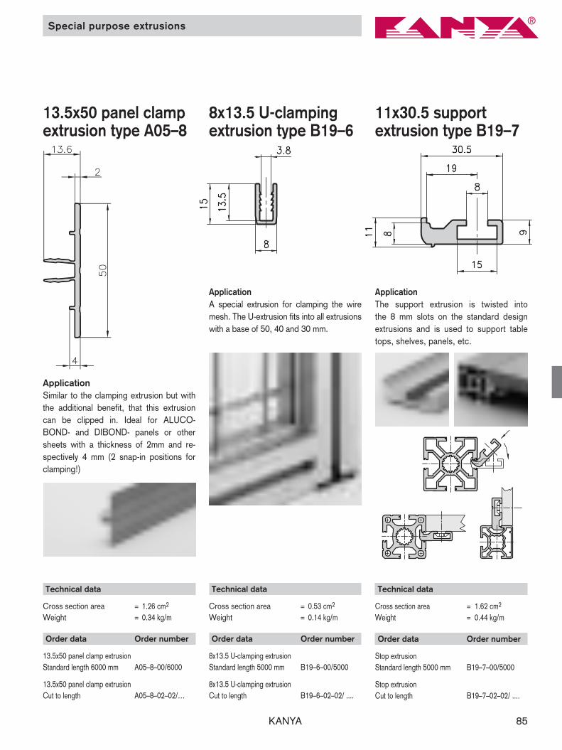
8x13.5 U-clampingextrusion type B19–6
Order data Order number
8x13.5 U-clamping extrusionStandard length 5000 mm B19–6–00/5000
8x13.5 U-clamping extrusionCut to length B19–6–02–02/ ....
Technical data
Cross section area = 0.53 cm2
Weight = 0.14 kg/m
ApplicationA special extrusion for clamping the wiremesh. The U-extrusion fits into all extrusionswith a base of 50, 40 and 30 mm.
ApplicationSimilar to the clamping extrusion but withthe additional benefit, that this extrusioncan be clipped in. Ideal for ALUCO-BOND- and DIBOND- panels or othersheets with a thickness of 2mm and re -spectively 4 mm (2 snap-in positions forclamping!)
13.5x50 panel clampextrusion type A05–8
Technical data
Cross section area = 1.26 cm2
Weight = 0.34 kg/m
Order data Order number
13.5x50 panel clamp extrusionStandard length 6000 mm A05–8–00/6000
13.5x50 panel clamp extrusionCut to length A05–8–02–02/…
ApplicationThe support extrusion is twisted into the 8 mm slots on the standard designextrusions and is used to support tabletops, shelves, panels, etc.
11x30.5 support extrusion type B19–7
Order data Order number
Stop extrusionStandard length 5000 mm B19–7–00/5000
Stop extrusionCut to length B19–7–02–02/ ....
Technical data
Cross section area = 1.62 cm2
Weight = 0.44 kg/m

KANYA86
Angle extrusion type A30–0/C30–0
Angle extrusion type A47–0
Angle extrusiontype A30–5
Order data Order number
38x38 angle extrusion raw Standard length 3000 mm A30–0–00/3000
38x38 angle extrusion raw Cut to length A30–0–02–02/…
31x31 angle extrusion raw Standard length 3000 mm C30–0–00/3000
31x31 angle extrusion raw Cut to length C30–0–02–02/…
Order data Order number
60x120 angle extrusion rawStandard length 3600 mm A47–0–00/3600
60x120 angle extrusion rawCut to length A47–0–02–02/…
Order data Order number
25x35 angle extrusion rawStandard length 5000 mm A30–5–00/5000
25x35 angle extrusion rawCut to length A30–5–02–02/…
Application Source material for floor bolting bracketsor for reinforcements.
Application Source material for mounting and fixingbrackets or as support bracket.
Dimensions
Type A B CA30–0 38 21 8C30–0 31 17 6
Angle extrusion
Technical data
Cross section area = 17.15 cm2
Weight = 4.63 kg/m
Technical data
Cross section area = 2.74 cm2
Weight = 0.74 kg/m
Technical Data
A30–0 C30–0Cross section area = 5.52 cm2 3.46 cm2
Weight = 1.49 kg/m 0.94 kg/m

KANYA 87
Angle extrusiontype A30–3
Angle extrusiontype C30–3
Angle extrusiontype A30–1
Application These very strong angle extrusions are thesource material for the mounting brackets.They’re also used to reinforce heavily loaded constructions.
Angle extrusion
Order data Order number
100x100 angle extrusion raw Standard length 3000 mm A30–3–00/3000
100x100 angle extrusion rawCut to length A30–3–02–02/…
Order data Order number
70x70 angle extrusion rawStandard length 3000 mm C30–3–00/3000
70x70 angle extrusion raw Cut to length C30–5–02–02/…
Order data Order number
60x60 angle extrusion rawStandard length 3000 mm A30–1–00/3000
60x60 angle extrusion raw Cut to length A30–1–02–02/…
Technical data
Cross section area = 23.63 cm2
Weight = 6.38 kg/m
Technical data
Cross section area = 9.23 cm2
Weight = 2.49 kg/m
Technical data
Cross section area = 10.15 cm2
Weight = 2.75 kg/m
KANYA88
Hinge extrusions / handle strip extrusion
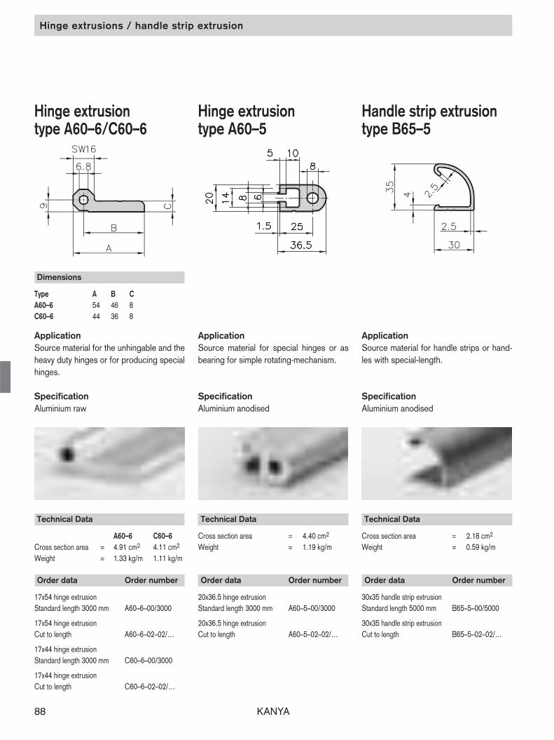
Hinge extrusion type A60–6/C60–6
Hinge extrusion type A60–5
Handle strip extrusion type B65–5
Order data Order number
17x54 hinge extrusionStandard length 3000 mm A60–6–00/3000
17x54 hinge extrusion Cut to length A60–6–02–02/…
17x44 hinge extrusionStandard length 3000 mm C60–6–00/3000
17x44 hinge extrusionCut to length C60–6–02–02/…
Order data Order number
20x36.5 hinge extrusionStandard length 3000 mm A60–5–00/3000
20x36.5 hinge extrusionCut to length A60–5–02–02/…
Application Source material for the unhingable and theheavy duty hinges or for producing specialhinges.
Specification Aluminium raw
Application Source material for special hinges or asbearing for simple rotating-mechanism.
SpecificationAluminium anodised
Application Source material for handle strips or hand-les with special-length.
Specification Aluminium anodised
Dimensions
Type A B CA60–6 54 46 8C60–6 44 36 8
Technical Data
Cross section area = 4.40 cm2
Weight = 1.19 kg/m
Order data Order number
30x35 handle strip extrusionStandard length 5000 mm B65–5–00/5000
30x35 handle strip extrusionCut to length B65–5–02–02/…
Technical Data
Cross section area = 2.18 cm2
Weight = 0.59 kg/m
Technical Data
A60–6 C60–6Cross section area = 4.91 cm2 4.11 cm2
Weight = 1.33 kg/m 1.11 kg/m

KANYA 89
Rectangular tube
55x55 rectangular tubetype A19–5
Application With the rectangular tube and with thecombination of a 50x50 extrusion a tele -scope function can be easily created. Can also be used as a guidance for acounter balance in a construction with alift gate in addition to many «classic» rectangular tube applications.
Order data Order number
55x55 rectangular tubeStandard length 6000mm A19–5–01/6000
55x55 rectangular tubeCut to length A19–5–02–02/….
Technical Data
Ix,y = 21.58 cm4
Wx,y = 7.85 cm3
Cross section area = 4.64 cm2
Weight = 1.25 kg/m
Counter balance

KANYA90
The Original / PVS connectors
KANYA 91
The Original / PVS connectors
KANYA connection technology
The extrusion connection system PVS® opens up new possibilities for all structural de-sign problems, whether for machinery, transfer and handling systems, guards, machineenclosures, work benches, laboratory facilities, cabinets, room partitions or exhibitionstands. Rectangular, round, square or diagonal, fixed or swivelling: KANYA is the perfectsolution.
Quick, secure connections:KANYA PVS makes it possible to erect any structure in a very short time. The systemcenters around KANYA’s own invention, the internationally patented PVS connector. Anyextrusions can be joined together securely.
Simple and versatile assembly:The two fundamentals which allow you to build a structure to your own design are easeof assembly and a comprehensive range of extrusions and accessories. Modifications oradditions can be easily made, when the need arises, without wasting any material.
Highly cost-effective:Any part can be customised. There is no need for expensive finishing or surface treat-ments. Expensive construction is minimised, saving time and reducing costs. All the partscan be reused repeatedly since all joints are simple to dismantle. That’s what makes thissystem the most cost effective you can buy in the long run.
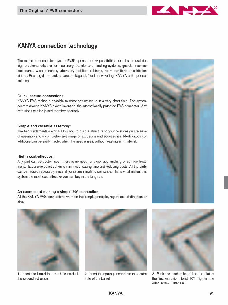
An example of making a simple 90º connection.All the KANYA PVS connections work on this simple principle, regardless of direction orsize.
1. Insert the barrel into the hole made inthe second extrusion.
2. Insert the sprung anchor into the centrehole of the barrel.
3. Push the anchor head into the slot ofthe first extrusion; twist 90°. Tighten theAllen screw. That’s all.

KANYA92
PVS-connectors
The round anchor head allows the extrusionsto be set in any position, however it must firstbe pushed into the retaining slot. The univer-sal connector is also available in stainlesssteel or providing electrical bonding.
The milled anchor head allows extrusions to be ad-ded subsequently. Two types of anchor are neededto guarantee that every extrusion position is possi-ble. The standard connector is also available instainless steel or providing electrical bonding.
Similar to the standard connection, howe-ver with the possibility of connecting diffe-rent extrusion bases among one another.
1. Universal connections
PVS®-connectors
The formed anchor head, 15°, 30° and45° in both left and right designs, or withan articulated anchor head for all otherangled connections.
5. Mitre connections
This versatile anchor can be swivelledfrom 0°–90°.
6. Double mitre connections
The threaded anchor enables the extrusi-on to be attached to other structures.
These plastic caps cover the screw holesand protect it from dirt as well as improvethe aesthetics.
8. Threaded connections 9. Plastic caps for connectors
The rigid connector guarantees an extre-mely stable extrusion extension.
7. Extrusion extension connections
The special anchor, which is available indifferent lengths, makes parallel and crossconnections.
4. Special connections
2. Standard connections 3. Combination connections

KANYA 93
2. Standard connectors
20 30 40 50AB20-10 AB20-10 A20-10CB20-10 CB20-10 C20-10B20-10 B210-10 B210-10
D20-10 D210-10 D210-10DD20-10 DD210-10 DD210-10
C20-50B210-50 B210-50
50 40 30 20A20-20 AB20-20 AB20-20
C20-20 CB20-20 CB20-20B210-20 B210-20 B20-20D210-20 D210-20 D20-20DD210-20 DD210-20 DD20-20C20-51B210-51 B210-51
Extrusions with a base of5040302020 core hole 6.0 mm
C02-8 / C03-8B01-8
20 30 40 50AB20-10 AB20-10 A20-10 A20-10CB20-15 CB20-15 C20-15 C20-15B20-15 B20-15 B210-15 B210-15on request x A20-50 A20-50on request x x xon request x x x
50 40 30 20A20-20 A20-20 AB20-20 AB20-20C20-25 C20-25 CB20-25 CB20-25B210-25 B210-25 B20-25 B20-25A20-51 A20-51 x on requestx x x on requestx x x on request
Extrusions with a base of504030
A02-8C02-8 / C03-8
B01-8
4. Special connectors
Order number Order number
Order number Order number
20 30 40 50A20-90 (-I/-P)*
C20-90 (-I/-P)* C20-90 (-I/-P)*B20-90 B210-90 (-I/-P)* B210-90 (-I/-P)*
D20-90 D20-90 D210-90 (-I/-P)* D210-90 (-I/-P)*DD20-90 DD20-90 DD210-90 DD210-90
A20-95C20-95 C20-95
B20-95 B210-95 B210-95*. . . . -P = universal connectors with electrical bonding*. . . . -I = Universal connectors stainless steel
50 40 30 20A20-90 (-I/-P)*C20-90 (-I/-P)* C20-90 (-I/-P)*B210-90 (-I/-P)* B210-90 (-I/-P)* B20-90D210-90 (-I/-P)* D210-90 (-I/-P)* D20-90 D20-90DD210-90 DD210-90 DD20-90 DD20-90A20-95C20-95 C20-95B210-95 B210-95 B20-95*. . . . -P = universal connectors with electrical bonding*. . . . -I = Universal connectors stainless steel
Extrusions with a base of5040302020 core hole 6.0 mm
A02-8C02-8 / CO3-8
B01-8
20 30 40 50A20-10(-I/-P)*
C20-10(-I/-P)*B20-10(-I/-P)*
D20-10(-I/-P)*DD20-10
A20-50C20-50
B20-50*. . . . -P = universal connectors with electrical bonding*. . . . -I = Universal connectors stainless steel
50 40 30 20A20-20(-I/-P)*
C20-20(-I/-P)*B20-20(-I/-P)*
D20-20(-I/-P)*DD20-20
A20-51C20-51
B20-51*. . . . -P = universal connectors with electrical bonding*. . . . -I = Universal connectors stainless steel
Extrusions with a base of5040302020 core hole 6.0 mm
A02-8C02-8 / CO3-8
B01-8
1. Universal connectors
3. Combination connectors
Order number Order number
Order number Order number
Universal-, standard- and special connectors

KANYA94
20* 20 30 40 50DD221-� D221-� B221-� C22-� A22-�DD221-� D221-� B221-� C22-�DD22-� D22-� B22-�DD22-� D22-�
Code � 15° = -15, � 30° = -30, � 45° = -45 *core hole 6.0 mm
20 30 40 50D221-00 B221-00 C22-00 A22-00D221-00 B221-00 C22-00D22-00 B22-00D22-00
50 40 30 20 20*A23-� C23-� B231-� D231-� DD231-�
C23-� B231-� D231-� DD231-�B23-� D23-� DD23-�
D23-� DD23-�Code � 15° = -15, � 30° = -30, � 45° = -45 *core hole 6.0 mm
Extrusions with a base of50403020
5a. Mitre connectors with formed anchor
Extrusions with a base of50403020
50 40 30 20A22-00 C22-00 B221-00 D221-00
C22-00 B221-00 D221-00B22-00 D22-00
D22-00
5b. Mitre connectors with an articulated anchor
30 40 50B221-� C22-� A22-�B221-� C22-�B22-�
Code � 15° = -19, � 30° = -39, � 45° = -49
50 40 30A23-� C23-� B231-�
C23-� B231-�B23-�
Code � 15° = -19, � 30° = -39, � 45° = -49)
Extrusions with a base of504030
5c. Mitred connectors with an formed anchor 90°
30 40 50B221-90 C22-90 A22-90B221-90 C22-90B22-90
50 40 30A22-90 C22-90 B221-90
C22-90 B221-90B22-90
Extrusions with a base of504030
5d. Mitred connectors with an articulated anchor 90°
Order number Order number
Order number Order number
Order number Order number
Order number Order number
Overview of the PVS connectors

KANYA 95
6. Double mitre connectors
50 40 30 20 20* A02-8 C02-8 B01-8A24-19
C24-19B24-19
D24-19–
A24-59C24-59
B24-59*core hole of 6.0 mm
Extrusions with a base of5040302020 core hole 6.0 mm
A02-8C02-8 / C03-8
B01-8
Thread M6 M8on request A20-60on request C20-60B20-66 B20-60D20-66 D20-60DD20-66on request A20-65on request C20-65on request B20-65
Extrusions with a base of5040302020 core hole 6.0 mm
A02-8C02-8 / C03-8
B01-8
8. Threaded connectors
B01-8 C02-8 A02-8 20* 20 30 40 50A24-10
C24-10B24-10
D24-10DD24-10
A24-51C24-51
B24-51*core hole of 6.0 mm
7. Extrusion extension connectors
Extrusions with a base of5040302020 core hole 6.0 mm
A02-8C02-8 / C03-8
B01-8
B01-8 C02-8 A02-8 20* 20 30 40 50A24-00
C24-00B24-00
D24-00DD24-00
A24-50C24-50
B24-50*core hole of 6.0 mm
Order number Order number
Order number
Order number
Overview of the PVS connectors
KANYA96
Connectors-accessories
Order data Order number
Plastic cap Base 40/50 A40–99Base 30 B40–99
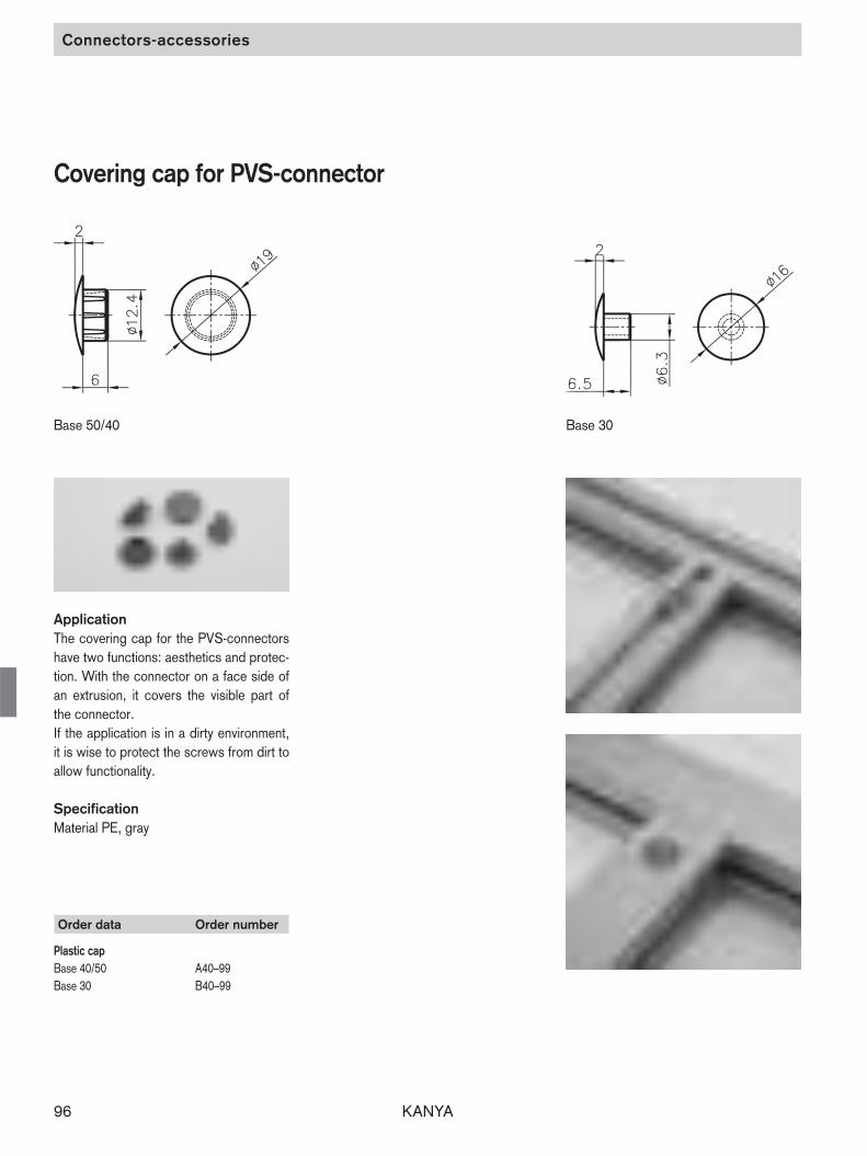
Covering cap for PVS-connector
Application The covering cap for the PVS-connectorshave two functions: aesthetics and protec-tion. With the connector on a face side ofan extrusion, it covers the visible part ofthe connector. If the application is in a dirty environment,it is wise to protect the screws from dirt toallow functionality.
SpecificationMaterial PE, gray
Base 50/40 Base 30

KANYA 97
5 353025201510
8000
0
0
1000
2000
3000
4000
5000
6000
7000
9000
10000
11000
12000
13000
12
34
5
6
7
8
910
11
1213 14
Fs
Fz
No. extrusion joints
1 50x50 1
2 40x40 1
3 30x30 1
4 30x50 1
5 40x80 2
6 30x100 2
7 50x100 2
No. extrusion joints
8 50x150 3
9 40x120 3
10 80x80 4
11 40x160 4
12 100x100 4
13 80x160 8
14 100x200 8
Thrusts
That chart shows the shearing forces inrelation to torque and number of connec-tors of the most important extrusion com-binations. At a torque of 30Nm lies the shearing for-ce for a connection with one connector atapproximately 400N.
Recommended torque: Extrusion base 50/40: 30–35Nm Extrusion base 30/20 20–25Nm
Suggestion: The tightening torques should not exceed35Nm: ➩ The anchor head may be damaged or broken.
Tractive forces
Those in the chart stated tractive forcesare approximate value. Conditions: Preload of connectors withmax. torque!
Connecting technique
Torque (Nm)
Technical data for aluminium extrusion connectors
She
arin
g fo
rce
F (N
)
Tractive force Fz FzExtrusion Universal connectors Standard connectors
Base 50 14’000N 10’000N
Base 40 14’000N 10’000N
Base 30 4’000N 3’500N
Base 20 2’000N 1’800N

KANYA98
PVS®-EASY

KANYA 99
Connecting technique
Ripped open slot PVS®-EASY screw in (self-cutting)
Extrusion mounting
Breaking slot (elevation nut)
Allen key with ballhead
Norm screw DIN 912
Centering Thread cutting notch
Self-cutting thread
extrusion nut
This innovative connecting technology ispatented in the EU and in other importantindustrial countries. It boasts 3 significantcharacteristics: – simple – high-strength – cost-efficient
The self-cutting thread-insert with a fixedscrew DIN 912 will be screwed in the cen-tral extrusion hole. By ripping off the slot nthe extrusion, access to the screw is ena -bled. The screw and the nut which is set inthe other extrusion result in an extremelystrong connection.
On the extrusions without a rip off slot, theopening will be machined (for examplewith a router).
Order data Order number
Universal connector PVS®-EASYextrusion base 50 AE20–00 extrusion base 40 CE20–00 extrusion base 30 BE20–00
Remark PVS®-EASY : special steel
surface treated
screw: steel 8.8, galvanized extrusion nut: steel 8.8, galvanized
Scope of delivery PVS®-EASY, screw, extrusion nut
KANYA connecting technique: PVS®-EASY

KANYA100
PVS®-LIGHT

KANYA 101
A
1
2
3
4
B A B
Connection technology
PVS light(with a flange plate)
Make LIGHT work ofconnecting extrusions!
PVS superlight(without a flange plate)
Assembly instruction:
1. Insert the expansion sleeve into the extru sion core hole (set in 0.5 to 1 mm).
2. Tighten the adjusting screw (to the correcttorque).
3. Fix the flange plate in place using the round-headed screw.
4. Screw extrusion A tightly to extrusion Busing the flange plate – that’s all there is toit.
Assembly instructions:
1. Insert the expansion sleeve into the extrusioncore hole. Allow the flats to protrude by 1.5(Ø 12.1) or 3 mm (Ø 13.7) and turn it to therequired position using an extrusion.
2. Tighten the adjusting screw (to the correcttorque).
3. Drill a stepped hole of Ø 8/14 into extrusionB.
4. Insert and tighten the socket-head cap screw – that’s all there is to it.
Whether you are connecting extrusionswith a small drilled hole or without any additional machining at all, the KANYAlight system will save you time and money. Because of the modular design principle,the extrusions can be combined in virtuallyany configuration. The expansion sleevecan be used in any extrusions with coreholes of ( 13.7 mm and 12.1 mm. )See for yourself from these assembly instructions just how simple and reliablethe KANYA LIGHT system really is!

KANYA102
L
10Profillänge = L-2010
Expansion sleeves / Flange plates
Expansion sleeves Flange plates
Order data Order number
Extrusions of base 40 and 50 A20-00(core hole Ø13.7)
Extrusions of base 20 and 30 B20-00(core hole Ø12.1)
ApplicationThe fastening screw is inserted into theexpansion sleeve. One or two expansionsleeves are required in each of the lightversions, depending on the number of extrusion core holes.
Tightening torquesAdjusting screw:
min. 10 Nm, max. 12 NmFastening screw:
min. 7 Nm, max. 9 Nm
FinishZinc-coated steel
Parts suppliedExpansion sleeve, adjusting screw
ApplicationThe flange plate secures the connectionbetween two extrusions. It is fixed to oneextrusion by means of a round-head socketscrew and to the other with extrusion nutsand socket-head cap screws.
Important! 10 mm must be allowed foreach flange plate (see sketch opposite) incalculating the extrusion cut length.
Fixing setExtrusion nuts, socket-head cap screws,round-headed socket screw(s)FinishAl, anodised in natural colours
Order data Order number
A B C D E F OFlange plate for extrusions50x50 50 50 25 – 7 36 6 A81-1050x100 50 100 25 50 7 86 6 A81-2040x40 40 40 20 – 5.5 29 5 C81-1040x80 40 80 20 40 5.5 69 5 C81-2030x30 30 30 15 – 2.8 24.4 5 B81-1030x50 30 50 25 – 2.8 44.4 5 B81-1130x100 30 100 25 50 2.8 94.4 5 B81-20
Fixing set for combinations50 base to 50 base (1 round-headed socket screw) A81-10-S50 base to 50 base (2 round-headed socket screws A81-20-S40 base to 40 base (1 round-headed socket screw) C81-10-S40 base to 40 base (2 round-headed socket screws) C81-20-S40 base to 50 base (1 round-headed socket screw) C81-11-S40 base to 50 base (2 round-headed socket screws) C81-21-S30 base to 30 base (1 round-headed socket screw) B81-10-S30 base to 30 base (2 round-headed socket screws) B81-20-S30 base to 40 base (1 round-headed socket screw) B81-11-S30 base to 40 base (2 round-headed socket screws) B81-21-S30 base to 50 base (1 round-headed socket screw) B81-12-S30 base to 50 base (2 round-headed socket screws) B81-22-S
Extrusion length=

KANYA 103
PVS®-LIGHT

KANYA104
Accessories

KANYA 105
Accessories
The QUICK way tocombine extrusions!
The extensive range of co-ordinated accessories enhances the cost-effectiveness of the KANYA modular extrusion building system. The best use ofsystem extrusions is made when working with all the matching parts.Getting everything from one supplier saves time and a great deal of irritation,not to mention money.Customer-specific accessories are available or can be specially made to order – yet another advantage of over 25 years experience in system building.
The A–Z of extrusion parts – we have them all!

KANYA106
Mounting bracket
Order data Order number
A B C D E F Ø M*100 30 8 35 55 12 9 – A30–30100 30 8 25 50 – 9 – A30–31100 75 8 25 50 – 9 – A30–32100 30 8 35 55 12 9 M6 A30–40100 20 8 35 55 12 6.5 – B30–30100 20 8 35 55 12 6.5 M6 B30–4070 25 5 20 40 – 6.5 – C30–3070 65 5 20 40 – 6.5 – C30–32
*insert
Order data Order number
A B C D E F Ø M*60 20 8 45 – 12 6.5 – B30–1060 20 8 45 – 12 6.5 M6 B30–2060 30 8 45 – 12 9 – A30–1060 30 8 45 – 12 9 M6 A30–2038 30 8 25 – – 9 – A30–0038 80 8 25 50 – 9 – A30–0231 20 6 20 – – 6.5 – C30–0031 60 6 20 40 – 6.5 – C30–02
*insert
Mounting brackets
ApplicationMounting brackets are simple joining partswhich can also be used in combinationwith PVS. They are used primarily for rein-forcement. They can also be used for fixing panels in place thanks to the integralthreaded insert.
SpecificationAluminium, matt,anodised in natural colours

KANYA 107
Mounting bracket / Clamping block
Clamping blockMounting bracket anddowel
ApplicationThe mounting bracket and dowel are usedin any application where the extrusions aresubjected to torsion but must not twist. Asafe extrusion connection.
SpecificationAluminium, matt, anodised in natural colours
Order data Order number
B Ø M30 9 – A30–1120 6.5 – B30–1130 9 M6 A30–2120 6.5 M6 B30–21
ApplicationTo connect two extrusions of base50 or 40 in parallelor crossing. Two blocks are required to create aparallel connection.
SpecificationBlock: Aluminium, matt, anodised
in natural coloursScrew: Zinc-coated steel
Parts supplied1/2 clamping block(s)Screws / threaded plates
Order data Order number
Raw block extrusionBase 50Standard length 3000 mm A34–0–00/3000Cut to length A34–0–02–02/ …Base 40Standard length 3000 mm C34–0–00/3000Cut to length C34–0–02–02/…
Order data Order number
BaseSingle clamping blocks 50 40Cross connection A34–01 C34–01Parallel connection A34–11 C34–11Double clamping blocksCross connection A34–02 C34–02Parallel connection A34–22 C34–22
KANYA108
Uniblocks / Clamping blocks
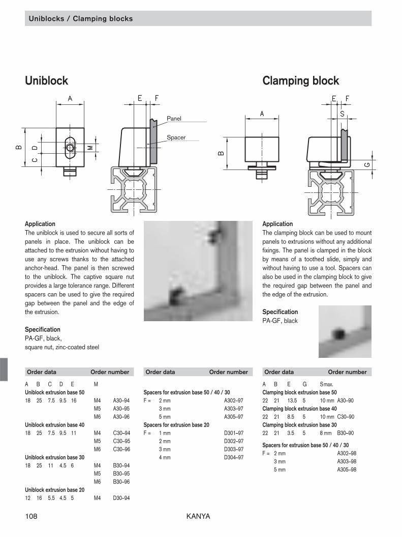
Uniblock
ApplicationThe uniblock is used to secure all sorts ofpanels in place. The uniblock can be attached to the extrusion without having touse any screws thanks to the attached anchor-head. The panel is then screwedto the uniblock. The captive square nutprovides a large tolerance range. Differentspacers can be used to give the requiredgap between the panel and the edge ofthe extrusion.
SpecificationPA-GF, black,square nut, zinc-coated steel
Order data Order number
A B C D E MUniblock extrusion base 5018 25 7.5 9.5 16 M4 A30–94
M5 A30–95M6 A30–96
Uniblock extrusion base 4018 25 7.5 9.5 11 M4 C30–94
M5 C30–95M6 C30–96
Uniblock extrusion base 3018 25 11 4.5 6 M4 B30–94
M5 B30–95M6 B30–96
Uniblock extrusion base 2012 16 5.5 4.5 5 M4 D30–94
Order data Order number
Spacers for extrusion base 50 / 40 / 30F = 2 mm A302–97
3 mm A303–975 mm A305–97
Spacers for extrusion base 20F = 1 mm D301–97
2 mm D302–973 mm D303–974 mm D304–97
Clamping block
ApplicationThe clamping block can be used to mountpanels to extrusions without any additionalfixings. The panel is clamped in the blockby means of a toothed slide, simply andwithout having to use a tool. Spacers canalso be used in the clamping block to givethe required gap between the panel andthe edge of the extrusion.
SpecificationPA-GF, black
Order data Order number
A B E G Smax.Clamping block extrusion base 5022 21 13.5 5 10 mm A30–90Clamping block extrusion base 4022 21 8.5 5 10 mm C30–90Clamping block extrusion base 3022 21 3.5 5 8 mm B30–90
Spacers for extrusion base 50 / 40 / 30F = 2 mm A302–98
3 mm A303–985 mm A305–98
Panel
Spacer

KANYA 109
Brackets / T-bolts
T-bolts
ApplicationT-bolts are used to fasten all types of components and are simple to insert, evenafter assembly. The anti-twist shape isa help during assembly.
Specification8.8 steel, zinc-coated
Scope of deliveryScrew, hexagonal nut, washer
Order data Order number
extrusion baseMxL 50 /40 30M8x20 A35–20M8x25 A35–25M8x30 A35–30M8x40 A35–40M8x60 A35–60
M6x15 B35–15M6x18 C35–18M6x20 B35–20M6x25 C35–25M6x30 C35–30 B35–30M6x40 B35–40
ApplicationThe fixing angle is used to mount additional equipment, panelling, worktops, valves, electrical switchgear, etc.The advantage of these is that they are slotted on one side, allowing fine adjustment.
SpecificationAluminium, matt, anodised in natural colours
Order data Order number
Through- ThreadA B C D E S Txt Ø Thread hole Ø M45 45 20 25 25 5 20x6.5 6.2 M6 A30–76 A30–8635 25 20 19 15 5 20x6.5 4.2 M4 A30–54 A30–6435 25 20 19 15 5 20x6.5 5.2 M5 A30–55 A30–6535 25 20 19 15 5 20x6.5 6.2 M6 A30–56 A30–66
25 25 15 14 15 4 13.5x6 3.2 M3 B30–53 B30–6325 25 15 14 15 4 13.5x6 4.2 M4 B30–54 B30–6425 25 15 14 15 4 13.5x6 5.2 M5 B30–55 B30–6525 25 15 14 15 4 13.5x6 6.2 M6 B30–56 B30–66
Further dimensions on request
Attachment bracket

KANYA110
Order data Order number
Halfround threaded plates Base 50Thread MM6 A32–61M8 A32–81M10 A32–91
Halfround threadedplates Base 50
ApplicationHalfround threaded plates can only beused with 50 mm base extrusions. Theseplates are only available threaded M10.
Specificationzinc-coated steel
Extrusions base of 50
Order data Order number
Double extrusion nuts BaseThread M 50 /40 30 /20M5 A32–58 B32–58M6 A32–68 B32–68
Measurement data
Extrusion base L T M50 /40 45 30 M6
30 18 M530 /20 45 30 M6
30 18 M5
ApplicationThe M6 double extrusion nuts are used forattaching hinges (page 136/137), M5 is usedfor arrester plate (page 143).
Base 30 and 20
Extrusions base of 50 and 40
Threaded plates Double threaded plates
Order data Order number
Threaded plates extrusion baseThread M 50 /40 30 /20 20M3 – B32–30 D32–30M4 A32–40 B32–40 D32–40M5 A32–50 B32–50 D32–50M6 A32–60 B32–60 D32–60M8 A32–80 – –
Extrusions base of 30 and 20
Extrusions base of 50 and 40
ApplicationFor attaching components which are anything up to medium weight.
SpecificationThreaded plate: zinc-coated steelRetaining spring: spring steel
Threaded plates

KANYA 111
Measurement data
Double extrusion nutsExtrusion base B H L T M50 18 12.2 80 50 M840 17 8 60 40 M8
Light double extrusion nutsExtrusion base B H L T M50 14 7.8 40 30 M640 13.6 5.9 40 30 M630 11 4.1 40 30 M630 11 4.1 30 18 M4
Order data Order number
Double extrusion nuts Extrusion baseThread M 50 40 30M8 A32–84 C32–84 –
Light double extrusion nutsM6 A32–67 C32–67 B32–67M4 – – B32–47
ApplicationDouble extrusion nuts should be used withPVS threaded connectors where extremelyhigh strength joints are required. Lightdouble extrusion nuts are used for the assembly of hinges (page 136/137) andquick-release fasteners (page 143).
Order data Order number
Light extrusion nuts Extrusion baseThread M 50 40 30M4 A32–45 C32–45 B32–45M5 A32–55 C32–55 B32–55M6 A32–65 C32–65 B32–65M8 A32–85 C32–85 B32–85
Extrusion (raw)1.5 m A32–52 C32–52 B32–52
Measurement data
Extrusion Base B H L50 14 7.8 2040 13.6 5.9 2030 11 4.1 20
Measurement data
Extrusion Base B H L S T Ø50 18 12.2 25 15 – –40 17 8 22 15 – –50/50 18 12.2 25 15 23 6.550/40 18 12.2 25 15 23 6.540/40 17 8 25 15 19 6.5
Extrusion nuts
Extrusion nutsClamping nuts
Order data Order number
Extrusion nuts Extrusion baseThread M 50 40M6 A32–63 C32–63M8 A32–83 C32–83
Clamping nuts 50/50 50/40 40/40M6 A32–69 A32–69 C32–69
ApplicationThe extrusion nut is recommended for securing heavy components with high tightening torques. Threaded plates and extrusion nuts are inserted before assembly into the end of the extrusion slots.
Specificationzinc-coated steel
ApplicationThe advantage of the light extrusion nuts isthat they can also be inserted diagonallyinto the extrusion slots. The disadvantageis that the tightening torques > 12 N mayresult in dents in the aluminium extrusion.Raw steel bars are available if you wish tomachine special nuts.
Light extrusion nuts Double extrusion nuts
KANYA112
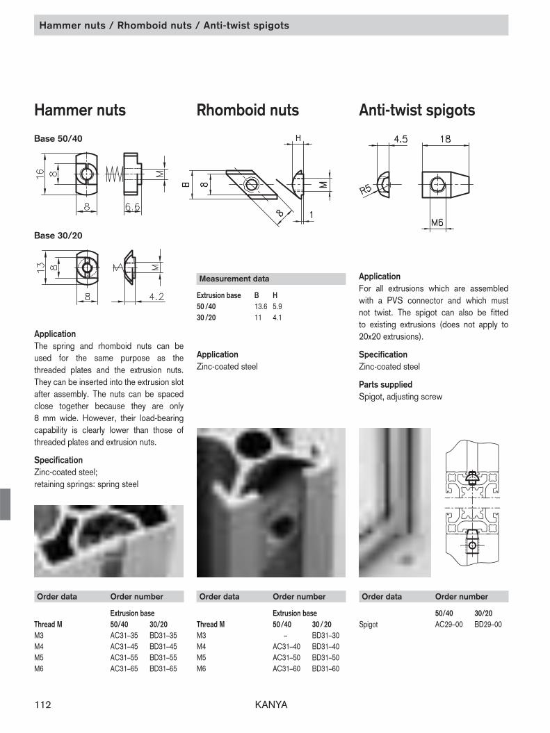
Hammer nuts / Rhomboid nuts / Anti-twist spigots
Measurement data
Extrusion base B H50 /40 13.6 5.930 /20 11 4.1
ApplicationZinc-coated steel
Order data Order number
Extrusion baseThread M 50/40 30/20M3 – BD31–30M4 AC31–40 BD31–40M5 AC31–50 BD31–50M6 AC31–60 BD31–60
Hammer nuts
ApplicationThe spring and rhomboid nuts can beused for the same purpose as the threaded plates and the extrusion nuts.They can be inserted into the extrusion slotafter assembly. The nuts can be spacedclose together because they are only 8 mm wide. However, their load-bearingcapability is clearly lower than those ofthreaded plates and extrusion nuts.
SpecificationZinc-coated steel; retaining springs: spring steel
Order data Order number
Extrusion baseThread M 50/40 30/20M3 AC31–35 BD31–35 M4 AC31–45 BD31–45 M5 AC31–55 BD31–55 M6 AC31–65 BD31–65
Anti-twist spigotsRhomboid nuts
ApplicationFor all extrusions which are assembledwith a PVS connector and which must not twist. The spigot can also be fitted to existing extrusions (does not apply to 20x20 extrusions).
SpecificationZinc-coated steel
Parts suppliedSpigot, adjusting screw
Order data Order number
50/40 30/20Spigot AC29–00 BD29–00
Base 50/40
Base 30/20
KANYA 113
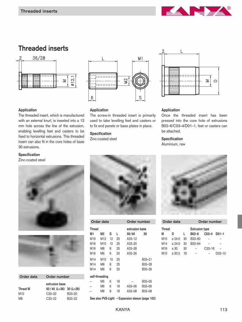
Order data Order number
Threat Extrusion typeM D L B02–6 C03–4 D01–1M10 ø 24.6 30 B33–60 – –M14 ø 24.6 30 B33–64 – –M16 ø 30 30 – C33–16 –M10 ø 30.5 18 – – D33–10
Threaded inserts
ApplicationThe threaded insert, which is manufacturedwith an external knurl, is inserted into a 12mm hole across the line of the extrusion,enabling levelling feet and casters to be fixed to horizontal extrusions. This threadedinsert can also fit in the core holes of base30 extrusions.
SpecificationZinc-coated steel
Order data Order number
Threat extrusion baseM1 M2 S L 50/40 30M16 M12 12 25 A33–12M16 M10 10 25 A33–20M16 M8 8 25 A33–28M16 M6 6 25 A33–26
M14 M10 10 25 B33–21M14 M8 8 25 B33–28M14 M6 6 25 B33–26
self-threading– M5 6 18 – B33–05– M6 6 18 A33–06 B33–06– M8 8 18 A33–08 B33–08
See also PVS-Light ➝ Expansion sleeve (page 102)
ApplicationThe screw-in threaded insert is primarilyused to take levelling feet and casters orto fix end panels or base plates in place.
SpecificationZinc-coated steel
ApplicationOnce the threaded insert has been pressed into the core hole of extrusions B02–6/C03–4/D01–1, feet or casters canbe attached.
SpecificationAluminium, raw
Order data Order number
extrusion base Threat M 50 /40 (L=36) 30 (L=28)M10 C33–20 B33–20M8 C33–22 B33–22
Threaded inserts

KANYA114
Levelling feet
ApplicationThese continuously variable levelling feetare used for many different applications.The cup is attached in such a way as tocompensate for uneven floors.
SpecificationCup: PA-GF blackBolt/locknut: 8.8 steel, zinc-coated
Order data Order number
MxL Ø F PA-GFM14x70 9 4000 N B45–54M14x120 9 4000 N B45–14M16x70 9 5000 N B45–50M16x120 9 5000 N B45–00
AluminiumM14x70 9 8000 N B45–55M14x70 – 8000 N B45–56M14x120 9 8000 N B45–03M14x120 – 8000 N B45–04
M16x70 9 10’000 N B45–51M16x70 – 10’000 N B45–52M16x120 9 10’000 N B45–01M16x120 – 10’000 N B45–02
SpecificationCup: PA-GF black or aluminiumbolt : 8.8 steel, zinc-coated
Other dimensions or special feet are available on demand.
Order data Order number
MxL D H FM10x70 50 30 2500 N B42–50M10x122 50 30 2500 N B42–00M14x65 50 25 3000 N B42–54M14x115 50 25 3000 N B42–14M16x65 50 25 3500 N B44–50M16x115 50 25 3500 N B44–00
ApplicationCup: glass-filled Polyamide (PA-GF) blackBolt/locknut: 8.8 steel, zinc-coatedAnti-slide pad: NBR rubber
Order data Order number
MxL D H FM8x37 19 20 1000 N B43–05M10x75 29 30 2000 N B43–10M10x75 39 30 3000 N B43–11M10x75 49 30 3000 N B43–12
Levelling feet
hole centers ø 68

KANYA 115
Order data Order number
MxL D FM14x65 30 3000 N B42–54–PM16x115 50 3500 N B44–00–P
Levelling feet withshock absorbers
Levelling feet
ApplicationThe aluminium levelling foot is availablewith a special shock absorber insert. This ensures that vibrating structures sitsecurely on the floor.
SpecificationCup: aluminiumRoundel: ø 80x18Multi-layer, non-slip, vibration-absorbent,composite structure.Bolt: 8.8 steel, zinc-coated
Order data Order number
MxL FM14x70 5000 N B45–56–DM14x120 5000 N B45–04–DM16x70 5000 N B45–52–DM16x120 5000 N B45–02–D
ApplicationIt is essential to use these levelling feet inapplications where electrostatic chargesmust be earthed. (See also PVS connectorswith electrical bonding)
SpecificationCup: aluminium rawBolt: aluminium raw
Electrically conductivelevelling feet

KANYA116
Order data Order number
extrusion base B ø50/40 40 8.5 A47–00(–S)*30 30 6.5 B47–00(–S)**Fixing kit: add –S to the order number
Base plates / Foot plates / Floor bolting bracket
Foot plates
ApplicationFor use with extrusions without a centralcore hole when fixing levelling feet and casters.
SpecificationAluminium, anodised in natural colours
Fixing kit*Screws and threaded inserts
Order data Order number
Extrusion A B C D100x100 100 100 50 50 A80–20(–S)*80x80 80 80 40 40 C80–20(–S)*40x80 40 80 – 40 C80–24(–S)**Fixing kit: add –S to the order number
Base plates
Order data Order number
Extrusion A B C D50x50 150 50 120 – A47–50(–S)*50x150 150 150 100 100 A47–70(–S)*100x100 200 100 150 70 A47–80(–S)*
40x40 120 40 90 – C47–40(–S)*80x80 150 80 120 50 C47–80(–S)**Fixing kit: add –S to the order number
Floor bolting bracket
ApplicationA floor bolting bracket is used when a system has been aligned and has to bebolted to the floor. It is very easy to usebecause its height can be adjusted in the extrusion slot and the bracket can beeasily secured to the floor using anchorbolts.
SpecificationAluminium, anodised in natural colours
Fixing kit*2 screws, 2 threaded plates, 2 washers
ApplicationWhen structures are subjected to heavyloads, structural stability is extremely important. The solid steel base platemeets this requirement in every respect,guaranteeing a high level of safety.
SpecificationSteel, gunmetal finish
Fixing kit*Bolt(s) M16x30

KANYA 117
Bolting brackets
Double bolting bracket
ApplicationAn advance on the normal floor boltingbracket, with the added advantage that itcan be used together with large levellingfeet (Ø 90). The double bolting bracket also secures the supporting extrusions intwo directions.
SpecificationSteel, powder-coated in black
Fixing kit*2 screws2 threaded plates2 washers
Order data Order number
Double bolting bracket A47–20(–S)**Fixing kit: add –S to the order number
Single bolting bracket
ApplicationSame as the aluminium floor boltingbracket with the added advantage that itcan be used together with large levellingfeet Ø 90.
SpecificationSteel, powder-coated in black
Fixing kit*2 screws2 threaded plates2 washers
Order data Order number
Single bolting bracket A47–22(–S)**Fixing kit: add –S to the order number
KANYA118
Leg bolt-down sockets
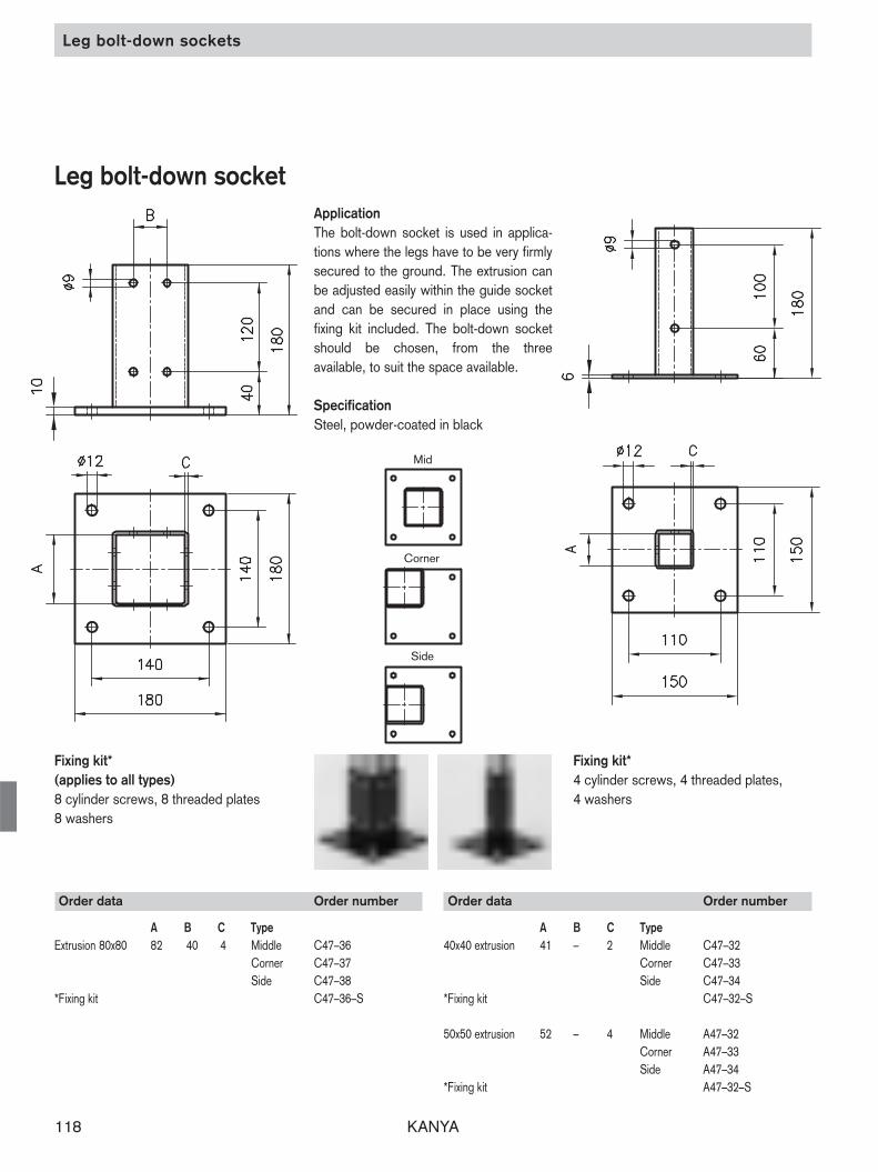
Leg bolt-down socket
Order data Order number
A B C TypeExtrusion 80x80 82 40 4 Middle C47–36
Corner C47–37Side C47–38
*Fixing kit C47–36–S
Order data Order number
A B C Type40x40 extrusion 41 – 2 Middle C47–32
Corner C47–33Side C47–34
*Fixing kit C47–32–S
50x50 extrusion 52 – 4 Middle A47–32Corner A47–33Side A47–34
*Fixing kit A47–32–S
ApplicationThe bolt-down socket is used in applica-tions where the legs have to be very firmlysecured to the ground. The extrusion canbe adjusted easily within the guide socketand can be secured in place using the fixing kit included. The bolt-down socketshould be chosen, from the three available, to suit the space available.
SpecificationSteel, powder-coated in black
Fixing kit*(applies to all types)8 cylinder screws, 8 threaded plates8 washers
Fixing kit*4 cylinder screws, 4 threaded plates,4 washers
Mid
Corner
Side

KANYA 119
Order data Order number
D B H A R Ø / MxL F no lock with lockCastor 50 19 70 25 72 Ø 10.3 400 N B48–50 B49–50Castor 50 19 70 25 72 M14x25 400 N B48–54 B49–54Castor 75 22 97 30 85 Ø 10.3 700 N B48–75 B49–75Castor 75 22 97 30 85 M14x25 700 N B48–74 B49–74
Castor 100 32 132 42 118 Ø 10.3 800 N B48–100 B49–100Castor 100 32 132 42 118 M16x25 800 N A48–100 A49–100Castor 125 32 158 42 118 Ø 10.3 1000 N B48–125 B49–125Castor 125 32 158 42 118 M16x25 1000 N A48–125 A49–125
For load of >800N we recommend castors with PO-wheels. Castors with PO-Wheels and other sizes, heavy duty and anti-static castors are available on request.
Order data Order number
D B H Ø / MxLNon-swivel castors 75 22 97 Ø 10.3 B48–77Non-swivel castors 75 22 97 M14x25 B48–78
Non-swivel castors 100 25 132 Ø 10.3 B48–107Non-swivel castors 100 25 132 M16x25 A48–108Non-swivel castors 125 32 158 Ø 10.3 B48–127Non-swivel castors 125 32 158 M16x25 A48–128
ApplicationCan be used in any application where mobility is required. There are four diameters of wheels available (with orwithout locks) depending on the load capacity required. Swivel and non-swivelcastors have the same load capacity. (F)The castors can be simply attached to theextrusions either with an M10 bolt or bymeans of an M16 / 14x25 threaded stud.
SpecificationFork: Steel, Ball bearingWheel: Rubber tyre, Ball bearing
R (lock)
Castors Non-swivel castors
Castors and non-swivel castors

KANYA120
neuA11091.tif
Rollers
ApplicationThis roller is suitable for heavy sliding doors, as a wheel for workpiece holdersor for general structures which have tomove freely.Insert the guide flange into the extrusionslot. Fit the flat roller onto the other side. This creates the perfect trolley/rail combination independent of the extrusiontolerance.
SpecificationPlastic roller, ballbearing mounted,steel spacer, gun-metal finishRadial load F = 500 N
Rollers
Order data Order number
Centric EccentricRoller with guide flange C48–00 C48–01Roller without guide flange C48–10 C48–11
Order data Order number
Roller PA B48–05
Order data Order number
Roller POM B48–03
ApplicationThis ball bearing-mounted roller is mainlyused in an assembly with the trolley extrusion, although it can also be attached directly to any extrusion.
SpecificationPA 6 black2 deep groove ball bearings with coverdisksF = 150 N
ApplicationSame as the PA roller, except that it fits small trolley extrusions. This low-costroller is ideal for smaller loads. It is not fitted with a ball bearing rollers.
SpecificationPOM blackF = 75 N

KANYA 121
Roller-mounted support / Double trolley
Roller-mounted support
drawn with roller offset
ApplicationSingle trolleys can be combined with anyother extrusions.Special trolleys or guides for moving com-ponents can be built very quickly. Refer topage 83 for dimensioned drawings ofthe extrusions.
Parts suppliedAluminium extrusion fitted with 1 roller and2 cover caps.F1 = 150 N | F2 = 75 N
Order data Order number
v = 0 mm v = 2 mmLarge roller-mounted support B37–50 B37–51Small roller-mounted support B37–30 B37–31
Double trolley
ApplicationA wide range of different applications ispossible with the double trolley. It providesa simple and mechanically reliable way ofcreating equipment chassis, sliding doors,lifting devices etc. Any lengths of extrusioncan be used. However, rollers for smalltrolleys should not be spaced any morethan 700 mm apart, and for large trolleysthe spaces between rollers should not ex-ceed 1000 mm.Trolleys are also available with more than2 rollers.Parts suppliedAluminium extrusion fitted with > 2 rollers.PVS connector and/or cover caps fitted.Load, see rollers.
Order data Order number
v = 0 mm v = 2 mmLarge double truck L= … with cover caps B37–52–02–02/ .... B37–53–02–02/ ....Large double truck L= … with PVS connector B37–52–10–10/ .... B37–53–10–10/ ....Small double truck L=… with cover caps B37–32–02–02/ .... B37–33–02–02/ ....Small double truck L=… with PVS connector B37–32–10–10/ .... B37–33–10–10/ ....
drawn without roller offset
End of the trolleywith a cover cap
End of the trolleywith a PVS connector
KANYA122
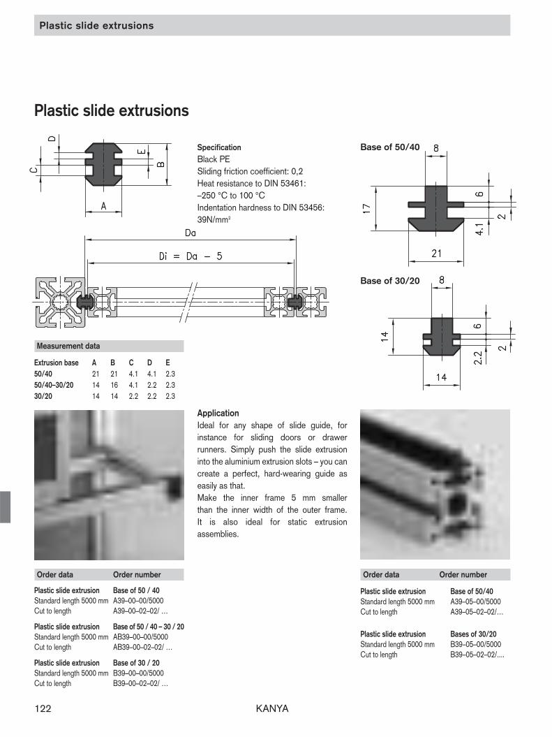
ApplicationIdeal for any shape of slide guide, for instance for sliding doors or drawer runners. Simply push the slide extrusion into the aluminium extrusion slots – you cancreate a perfect, hard-wearing guide as easily as that.Make the inner frame 5 mm smaller than the inner width of the outer frame. It is also ideal for static extrusion assem blies.
Plastic slide extrusions
Plastic slide extrusions
SpecificationBlack PESliding friction coefficient: 0,2Heat resistance to DIN 53461:–250 °C to 100 °CIndentation hardness to DIN 53456:39N/mm2
Order data Order number
Plastic slide extrusion Base of 50/40Standard length 5000 mm A39–05–00/5000Cut to length A39–05–02–02/…
Plastic slide extrusion Bases of 30/20Standard length 5000 mm B39–05–00/5000Cut to length B39–05–02–02/....
Base of 50/40
Base of 30/20
Measurement data
Extrusion base A B C D E50/40 21 21 4.1 4.1 2.350/40–30/20 14 16 4.1 2.2 2.330/20 14 14 2.2 2.2 2.3
Order data Order number
Plastic slide extrusion Base of 50 / 40Standard length 5000 mm A39–00–00/5000Cut to length A39–00–02–02/ …
Plastic slide extrusion Base of 50 / 40 – 30 / 20Standard length 5000 mm AB39–00–00/5000Cut to length AB39–00–02–02/ …
Plastic slide extrusion Base of 30 / 20Standard length 5000 mm B39–00–00/5000Cut to length B39–00–02–02/ …

KANYA 123
Plastic slide extrusions / Sliding hook
Order data Order number
Plastic slide extrusion Basis 50/40/30/20Standard length 5000 mm A69–0–00/5000
Plastic slide extrusionCut to length A69–0–02–02/....
Sliding hook
ApplicationFor single sliding doors, suspended fittings, cable supports and many otheruses. Fits all standard KANYA extrusions.
SpecificationPE, black
ApplicationThe sliding hook is ideally suited for suspended tool applications or as a cableguide. It is simply pressed into the extrusionslot and moves freely. Other lengths ofmultiple-hole versions are available on request.
Specification:Slider: PE, black
made from a plastic slideextrusion, A69–0–00load-bearing capacity: F = 300 N
Spring hook: chromium-plated steel
Order data Order number
No spring hook A69–00With a spring hook A69–01
Base of 50/40
Base of 30
ApplicationThis slide extrusion is mounted on the extrusion, acting as a sliding carrier forgoods or pallets. The slide extrusion canalso be used as a protective strip.
SpecificationPP, black
Order data Order number
Plastic slide extrusion Base of 50/40Standard length 5000 mm AC39–20–00/5000Cut to length AC39–20–02–02/…
Plastic slide extrusion Base of 30Standard length 5000 mm B39–20–00/5000Cut to length B39–20–02–02/…

KANYA124
Cable ducts
Cable ducts
ApplicationThe cable ducts are placed directly ontothe extrusions and are secured using either the retaining clips (see page 125) orextrusion nuts available. The duct is easyto open or close any time as it is fitted with a press-on cover. The slotted sides enable cables to be fed in and out at any point.
SpecificationUPVC, light grey(Standard lengths: solid cable duct 5000 mm, slotted cable duct 2000 mm)
Order data Order number
Cable ducts closed slotted75 mm wide cable duct Standard legths A38–00–00/5000 A38–01–00/2000
Cut to length A38–00–02/… A38–01–02/…
34 mm wide cable duct Standard legths C38–00–00/5000 C38–01–00/2000Cut to length C38–00–02/… C38–01–02/…
24 mm wide cable duct Standard legths B38–00–00/5000 B38–01–00/2000Cut to length B38–00–02/… B38–01–02/…
KANYA 125
Installation material
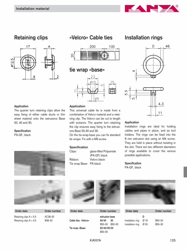
Installation rings«Velcro» Cable tiesRetaining clips
ApplicationInstallation rings are ideal for holding cables and pipes in place, and as tool holders. The rings can be fixed into the 8 mm extrusion slot using an M4 screw.They are held in place without twisting inthe slot. There are two different diametersof rings available to cover the various possible applications.
SpecificationPA-GF, black
ApplicationThe quarter turn retaining clips allow theeasy fixing of either cable ducts or thinsheet material onto the extrusions Base50, 40 and 30.
SpecificationPA-GF, black
Application This universal cable tie is made from acombination of Velcro material and a retai-ning clip. The Velcro can be cut to lengthwith scissors. The quarter turn retainingthe clip ensures easy fixing to the extrusi-ons Base 50,40 and 30. On the tie-wrap-base you can fix standardtie wraps. Fix with a M5-screw
Specification Clips: glass-filled Polyamide
(PA-GF) blackRibbon: Velcro black Tie wrap Base: PA black
Order data Order number
DInstallation ring Ø 18 B50–20Installation ring Ø 33 B50–30
Order data Order number
extrusion baseCable ties «Velcro» 50/40 30
B50–50 B50–53Tie wrap «Base» 50/40/30/20
B50–55
Order data Order number
Retaining clips A = 5.5 AC38–20Retaining clips A = 3.5 B38 –20
tie wrap «base»

KANYA126
End caps / Filler strips
Order data Order number
End caps 050x50 A40–10End caps 050x50 A40–19 (extr. A19–1)End caps 050x45° A40–80End caps 050x100 A40–20End caps 050x150 A40–30End caps 100x100 A40–50
End caps 40x40 C40–10End caps 40x40 C40–83 (extr. C03–8)End caps 40x80 C40–30End caps 40x120 C40–90End caps 80x80 C40–20 (extr. C01-2)End caps 80x80 C40–40End caps 40x45° C40–80
Order data Order number
End caps 30x30 B40–30End caps 30x30 B40–10 (extr. B01–1)End caps 30x30 B40–80 (extr. B01–8)End caps 30x30° B40–33End caps 30x45° B40–45End caps 30x60° B40–66End caps 30x50 B40–90End caps 30x60 B40–60End caps 60x60 B40–65End caps 30x95 B40–50End caps 30x100 B40–20End caps 30x120° B40–40End caps 30 oct. B40–15
End caps 20x20 D40–30End caps 20x20 D40–80 (extr. D03–8)End caps 20x47 D40–20End caps 20x40 D40–60End caps 20x150 D40–19End caps 20 oct. D40–10
Aluminium filler strip
ApplicationThese aluminium strips can be used to blank off the longitudinal slots on all extrusions with a base of 40 and 50. Theyare extremely easy to cut to length usingtin snips or shears. They can be suppliedat short notice in any RAL colour in additionto the standard colours (natural anodisedor black powder coated).
SpecificationAluminium 0.8x 10anodised with millimeter scale
ApplicationEnd caps are used as covers for the exposed ends of extrusions. They preventinjury from the sharp edges of the extrusions. Special centring elements make them easy to fix and prevent thecaps from twisting. Two end caps can beused together to cap off larger extrusions,eg extrusion 80x120 uses two 40x120 endcaps.
Order data Order number
Filler strip blackL = 1000 mm A39–10L = 2000 mm A39–12
Filler strip anodised mm-scaleL = 1000 mm A39–15 A39–16L = 2000 mm A39–17 A39–18
End caps
SpecificationPA-GF, black
Extrusion Cap heightBase of 50 / 40 4 mmBase of 30 / 20 3 mm

KANYA 127
ApplicationChannel reducing strips are used if 3, 4 or5 mm panels are to be inserted into theextrusion slots.
SpecificationGrey PVC for panels of 3, 4 or 5 mm inthicknessPlate insertion depth: 4 mm
Order data Order number
Channel reducing strip A = 3,5 mmStandard length 5000 mm A39–33–00/5000Cut to length A39–33–02–02/...
Channel reducing strip A = 4,5 mmStandard length 5000 mm A39–32–00/5000Cut to length A39–32–02–02/…
Channel reducing strip A = 5,5 mmStandard length 5000 mm A39–34–00/5000Cut to length A39–34–02–02/...
Filler strips / Channel reducing strips
PVC filler strips
ApplicationThe PVC filler strip can be clipped into the8 mm longitudinal slot on any extrusion after assembly and is available in grey orblack.
SpecificationGrey or black PVC
Order data Order number
Filler strips greyStandard length 5000mm A39–25–00/5000Cut to length A39–25–02–02/…
Filler strips blackStandard length 5000mm A39–26–00/5000Cut to length A39–26–02–02/…
Channel reducing strip
ApplicationFor thin sheets eg expanded metal, steelsheets, etc.
SpecificationGrey PVC for panels up to 3 mmPlate insertion depth: 4 mm
Order data Order number
Channel reducing stripStandard length 5000 mm A39–31–00/5000Cut to length A39–31–02–02/...

KANYA128
Channel reducing strips and filler strips / H-strip
ApplicationTo hold panels which are 6 mm thickness.They can also be inverted to blank off theslots on triple channel extrusions.
SpecificationGrey PVC for panels of 6 mm in thicknessPanel insertion depth: 11 mm
ApplicationUsed in combination with the B39–55channel reducing strip, this H-strip allowslift-on or lift-off panels to be inserted or removed.Bottom: B39–35Top: B39–55
SpecificationGrey PVC for panels of 4 or 6 mm inthickness
Order data Order number
Channel reducing strip extrusions 50A = 14.5 mmStandard length 5000 mm A39–50–00/5000Cut to length A39–50–02–02/…
Channel reducing strip extrusions 40A = 10 mmStandard length 5000 mm C39–50–00/5000Cut to length C39–50–02–02/…
Channel reducing strip extrusions 30A = 6.5 mmStandard length 5000 mm B39–50–00/5000Cut to length B39–50–02–02/…
Channel reducing strip extrusions B05–1A = 12 mmStandard length 5000 mm B39–55–00/5000Cut to length B39–55–02–02/…
Order data Order number
H-strip extrusions B05–1Standard length 5000 mm B39–35–00/5000Cut to length B39–35–02–02/…
Channel reducing strips and filler strips H-strip
KANYA 129
Supporting extrusion / Wedge extrusion
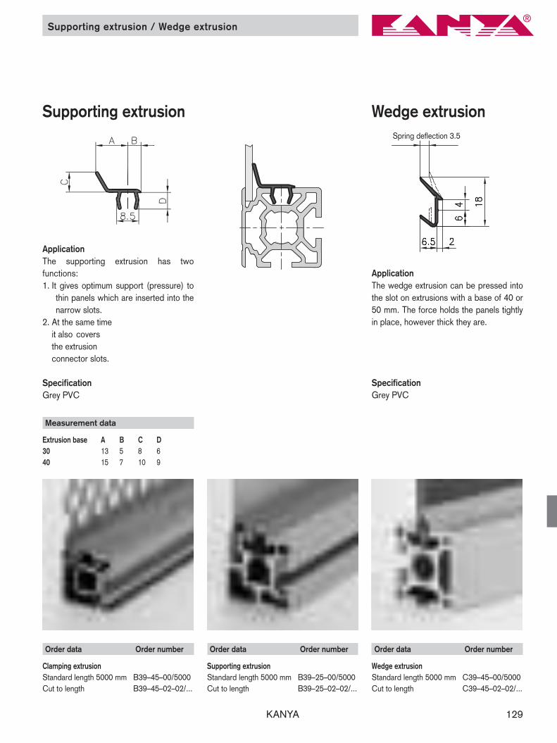
ApplicationThe wedge extrusion can be pressed intothe slot on extrusions with a base of 40 or50 mm. The force holds the panels tightlyin place, however thick they are.
SpecificationGrey PVC
Order data Order number
Wedge extrusionStandard length 5000 mm C39–45–00/5000Cut to length C39–45–02–02/...
Order data Order number
Clamping extrusionStandard length 5000 mm B39–45–00/5000Cut to length B39–45–02–02/...
Wedge extrusion
ApplicationThe supporting extrusion has two functions:1. It gives optimum support (pressure) to
thin panels which are inserted into thenarrow slots.
2. At the same time it also covers the extrusion connector slots.
SpecificationGrey PVC
Supporting extrusion
Order data Order number
Supporting extrusionStandard length 5000 mm B39–25–00/5000Cut to length B39–25–02–02/...
Spring deflection 3.5
Measurement data
Extrusion base A B C D30 13 5 8 640 15 7 10 9

KANYA130
Plastic extrusions
Semi-circular sealingstrip
Door sealing strip
Order data Order number
Semi-circular sealing stripStandard length 5000 mm A39–85–00/5000Cut to length A39–85–02–02/…
Order data Order number
Door sealing stripStandard length 5000 mm A39–88–00/5000Cut to length A39–88–02–02/…
ApplicationSealing strip for clean room technologyand many other applications. Fits all stan-dard KANYA extrusions.
SpecificationBlack neoprene rubber, oil-resistant.
ApplicationUsed to seal doors. Fits in all KANYAstandard extrusions base 40 + 50 – asdoes the semi-circular sealing strip.
SpecificationBlack soft PVC, oil-resistant, 57 Shore A
Safety-edge extrusion
Order data Order number
Saftey-edge extrusion Standard length 2000 mm C39–90
Application Mainly used as a personal safety-extrusionon automatic sliding doors and every -where there is danger of crushing parts. Itfits to the KANYA-extrusions of the base50 + 40.
Specification EPDM caoutchouc black

KANYA 131
Clamping sealing strip
ApplicationThis sealing strip is used to stabilise andseal panels. It is fitted after the panels areinserted.
SpecificationBlack neoprene rubber, oil-resistant.
Measurement data
A B CPanels 1–3 mm thick 13 9 4Panels 3–4 mm thick 10.5 7.5 3Panels 5–6 mm thick 10.5 6.2 3
Order data Order number
Clamping sealing stripPanels 1–3 mm thickStandard length 5000 mm A39–80–00/5000Cut to length A39–80–02–02/...
Panels 3–4 mm thickStandard length 5000 mm A39–81–00/5000Cut to length A39–81–02–02/...
Panels 5–6 mm thickStandard length 5000 mm A39–83–00/5000Cut to length A39–83–02–02/…
U-sealing strip
ApplicationThis sealing strip can be inserted into the 8 mm slots on any extrusions and is suitable for panels measuring between3 and 6 mm in thickness.
SpecificationBlack neoprene rubber, oil-resistant.
Order data Order number
U-sealing strip, A = 12 mm 40/30 mm baseStandard length 5000 mm B39–65–00/5000Cut to length B39–65–02–02/…
U-sealing strip, A = 18 mm 50 mm baseStandard length 5000 mm A39–65–00/5000Cut to length A39–65–02–02/…
Sealing strips
soft
Grid extrusion
Application Mainly used for holding steel-wire-mesh.The soft lips insulate the vibration andcompensats the different thicknesses. It’squalified for panels with 2–5 mm thick -ness.The grid extrusion fits into the base 50 and40.
Specification Hard- (soft) PVC, black
Order data Order number
Grid extrusion Standard length 5000 mm C39–70–00/5000Cut to length C39–70–02–02/…
KANYA132
Enclosures / Aluminium sheets
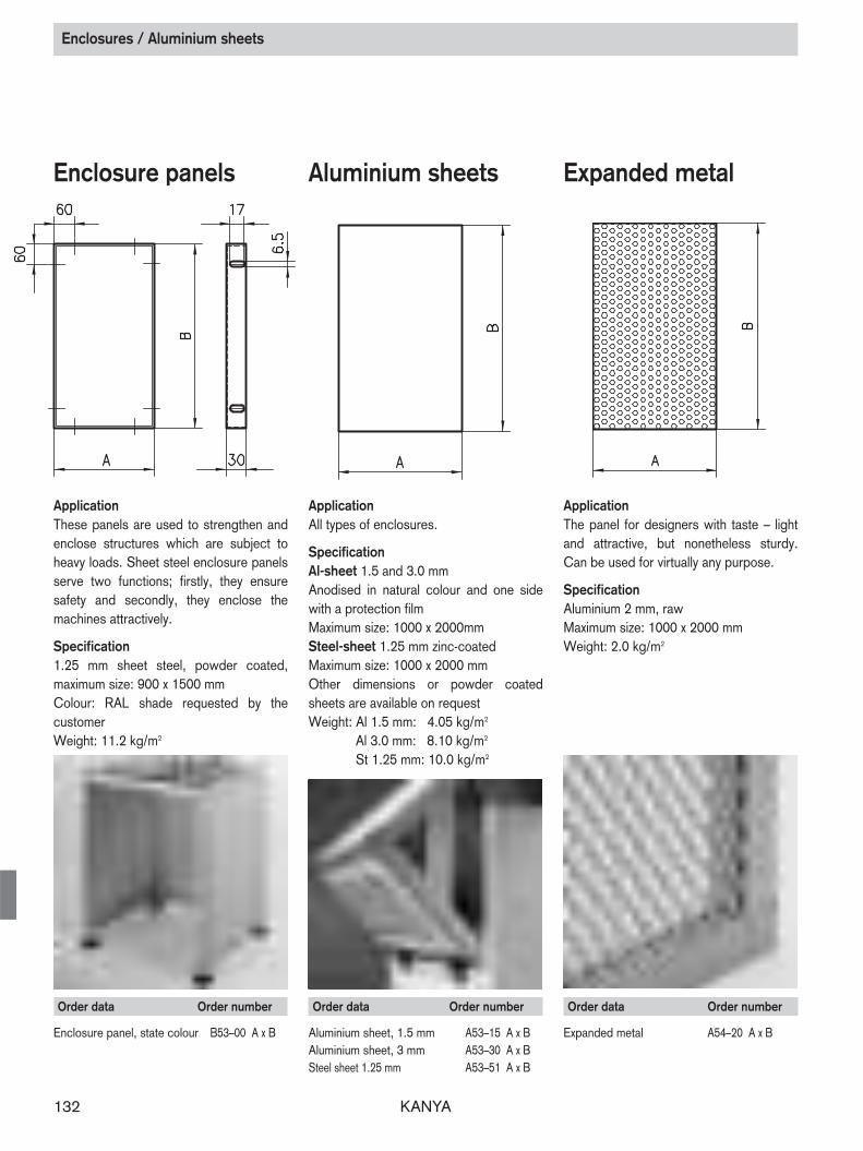
Enclosure panels Aluminium sheets
ApplicationThese panels are used to strengthen andenclose structures which are subject toheavy loads. Sheet steel enclosure panelsserve two functions; firstly, they ensure safety and secondly, they enclose the machines attractively.
Specification1.25 mm sheet steel, powder coated, maximum size: 900 x 1500 mmColour: RAL shade requested by the customerWeight: 11.2 kg/m2
ApplicationAll types of enclosures.
SpecificationAl-sheet 1.5 and 3.0 mmAnodised in natural colour and one sidewith a protection filmMaximum size: 1000 x 2000mmSteel-sheet 1.25 mm zinc-coatedMaximum size: 1000 x 2000 mmOther dimensions or powder coatedsheets are available on requestWeight: Al 1.5 mm: 4.05 kg/m2
Al 3.0 mm: 8.10 kg/m2
St 1.25 mm: 10.0 kg/m2
Order data Order number
Enclosure panel, state colour B53–00 A x B
Order data Order number
Aluminium sheet, 1.5 mm A53–15 A x BAluminium sheet, 3 mm A53–30 A x BSteel sheet 1.25 mm A53–51 A x B
Expanded metal
ApplicationThe panel for designers with taste – lightand attractive, but nonetheless sturdy.Can be used for virtually any purpose.
SpecificationAluminium 2 mm, rawMaximum size: 1000 x 2000 mmWeight: 2.0 kg/m2
Order data Order number
Expanded metal A54–20 A x B
KANYA 133
Panels
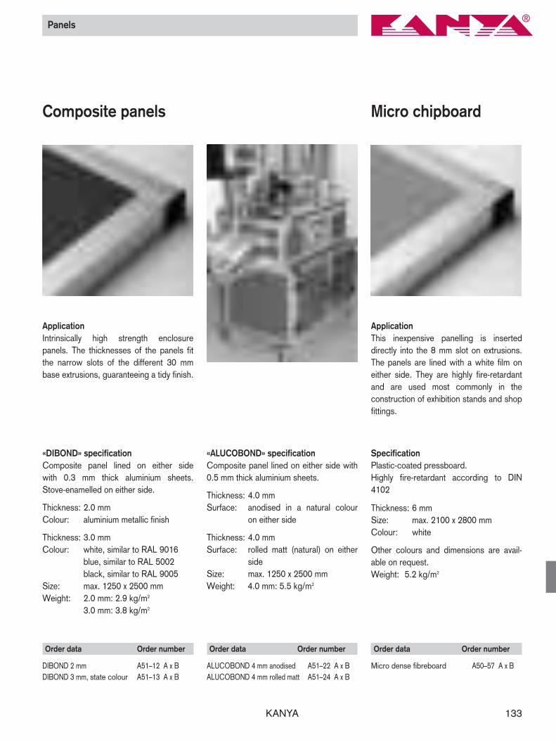
Composite panels
ApplicationIntrinsically high strength enclosure panels. The thicknesses of the panels fitthe narrow slots of the different 30 mm base extrusions, guaranteeing a tidy finish.
Order data Order number
DIBOND 2 mm A51–12 A x BDIBOND 3 mm, state colour A51–13 A x B
Micro chipboard
Order data Order number
Micro dense fibreboard A50–57 A x B
ApplicationThis inexpensive panelling is inserted directly into the 8 mm slot on extrusions.The panels are lined with a white film oneither side. They are highly fire-retardantand are used most commonly in the construction of exhibition stands and shopfittings.
«DIBOND» specificationComposite panel lined on either side with 0.3 mm thick aluminium sheets.Stove-enamelled on either side.
Thickness: 2.0 mmColour: aluminium metallic finish
Thickness: 3.0 mmColour: white, similar to RAL 9016
blue, similar to RAL 5002black, similar to RAL 9005
Size: max. 1250 x 2500 mmWeight: 2.0 mm: 2.9 kg/m2
3.0 mm: 3.8 kg/m2
Order data Order number
ALUCOBOND 4 mm anodised A51–22 A x BALUCOBOND 4 mm rolled matt A51–24 A x B
«ALUCOBOND» specificationComposite panel lined on either side with0.5 mm thick aluminium sheets.
Thickness: 4.0 mmSurface: anodised in a natural colour
on either side
Thickness: 4.0 mmSurface: rolled matt (natural) on either
sideSize: max. 1250 x 2500 mmWeight: 4.0 mm: 5.5 kg/m2
SpecificationPlastic-coated pressboard.Highly fire-retardant according to DIN4102
Thickness: 6 mmSize: max. 2100 x 2800 mmColour: white
Other colours and dimensions are avail-able on request.Weight: 5.2 kg/m2

KANYA134
Panels
Full-plastic panels
ApplicationFor enclosures subject to heavy loads.Suitable for metal machining and hot orcold forming. Plastic panels are inserteddirectly into the extrusion channels or fittedby means of A/B30–... fixing brackets orA64–... quick-release fasteners.
SpecificationRigid plastic foam, scratch-proof and impact-resistant,oil-resistanthighly fire-retardant according to DIN4102 (self-extinguishing)Thicknesses: 3, 4, 6, 8 mmSize: max. 1220 x 2440 mmWeight: 3 mm: 2.1 kg/m2
4 mm: 2.8 kg/m2
6 mm: 4.2 kg/m2
8 mm: 5.6 kg/m2
Colour: white
Other colours may be supplied on request.
Acrylic glass
Order data Order number
3 mm polycarbonate, state colour A50–33 A x B4 mm polycarbonate, state colour A50–34 A x B5 mm polycarbonate, state colour A50–35 A x B6 mm polycarbonate, state colour A50–36 A x B8 mm polycarbonate, state colour A50–38 A x B
Order data Order number
3 mm acrylic glass, state colour A50–13 A x B4 mm acrylic glass, state colour A50–14 A x B5 mm acrylic glass, state colour A50–15 A x B6 mm acrylic glass, state colour A50–16 A x B8 mm acrylic glass, state colour A50–18 A x B
ApplicationFor machine safety enclosures, room partitions and display cases. Suitable formetal machining and hot forming.
Specification for acrylic glassColours: transparent, blue, smoked
effect or tinted brownThicknesses: 3, 4, 5, 6, 8 mmSize: max. 2000 x 3000 mmWeight: 3 mm: 3.55 kg/m2
4 mm: 4.70 kg/m2
5 mm: 5.90 kg/m2
6 mm: 7.10 kg/m2
8 mm: 9.45 kg/m2
Specification for polycarbonateColours: transparent, tinted brownThicknesses: 3, 4, 5, 6, 8 mmSize: max. 2000 x 3000 mmWeight: 3 mm: 3.60 kg/m2
4 mm: 4.80 kg/m2
5 mm: 6.00 kg/m2
6 mm: 7.20 kg/m2
8 mm: 9.60 kg/m2
Order data Order number
3 mm all–plastic panel A50–63 A x B4 mm all–plastic panel A50–64 A x B6 mm all–plastic panel A50–66 A x B8 mm all–plastic panel A50–68 A x B
Polycarbonate
KANYA 135
Order data Order number
Suspension small B=12.5 mm B62–20Suspension large B=25.0 mm B62–25
Steel wire mesh / Suspended guard fittings
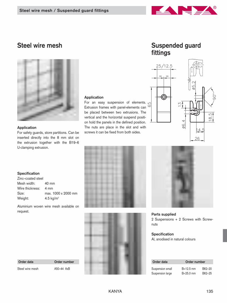
Steel wire mesh Suspended guard fittings
ApplicationFor safety guards, store partitions. Can beinserted directly into the 8 mm slot on the extrusion together with the B19–6 U-clamping extrusion.
SpecificationZinc–coated steelMesh width: 40 mmWire thickness: 4 mmSize: max. 1000 x 2000 mmWeight: 4.5 kg/m2
Aluminium woven wire mesh available onrequest.
Order data Order number
Steel wire mesh A50–44 AxB
Application For an easy suspension of elements.Extrusion frames with panel-elements canbe placed between two extrusions. Thevertical and the horizontal suspend positi-on hold the panels in the defined position.The nuts are place in the slot and with screws it can be fixed from both sides.
Parts supplied 2 Suspensions + 2 Screws with Screw-nuts
Specification Al, anodised in natural colours

KANYA136 KANYA136
Hinges
Aluminium hinges lift-off type
Plastic hinges fix
Application That the optimal pivoting characteristics is given for doors, windows ect, the designer needs a selection of hinges,which are fitting exactly.
Whether cost efficient plastic, attractivediecasting, or high-strength Aluminium hinges, the assortment gives you the pos-sibility to do the right choice.
Specification PA-GF blackPin: steel zinc coated
Specification PA-GF black Pin: steel zinc coated
Specification Al anodised natural coloursPin: steel zinc coated
Plastic hinges lift-offtype
Order data Order number
Plastic hingesBasis A B C D E F O links rechts50 96 48 55 28 48 48 6.5 A60–60–PA (–S)* A60–61–PA (–S)*50/40 86 48 50 28 48 38 6.5 AC6–60–PA (–S)* AC6–61–PA (–S)*50/30 77 48 45 28 48 29 6.5 AB6–60–PA (–S)* AB6–61–PA (–S)*40 76 48 45 28 38 38 6.5 C60–60–PA (–S)* C60–61–PA (–S)*40/30 67 48 40 28 38 29 6.5 CB6–60–PA (–S)* CB6–61–PA (–S)*30 58 48 35 28 29 29 6.5 B60–60–PA (–S)* B60–61–PA (–S)*
Aluminium hinges 50 92 50 54 30 46 46 6.5 A60–60 (–S)* A60–61 (–S)*50/40 82 50 49 30 46 36 6.5 AC6–60 (–S)* AC6–61 (–S)*40 72 50 44 30 36 36 6.5 C60–60 (–S)* C60–61 (–S)*
* Fixing kit: add- to the order number
Order data Order number
Base A B C D E F O50 76 50 56 30 38 38 6.3 A60–00–PA (–S)*50/30 63 50 43 30 25 38 6.3 AB6–00–PA (–S)*30 50 50 30 30 25 25 6.3 B60–00–PA (–S)*
*Fixing kit: add- to the order number
Image: right fixed type Image: left fixed type

KANYA 137KANYA 137
Hinges
Zn-diecasting hinges fixed type
Al-heavy duty hinges fixed type
Special hinges lift-off type
Specification GD-Zn, black powder coatedPin: steel zinc coatedwasher: PA-6, white
Specification Al, anodised natural colours Pin: steel zinc coated bush bearing: iglidur G, grey
Specification Al anodised natural colours Pin: steel zinc coated
Order data Order number
Zn-diecasting hingesBase A B C D E F O50 78 50 54 30 39 39 6.3 A60–20 (–S)*50/40 73 50 49 30 34 39 6.3 AC6–20 (–S)*50/30 67 50 43 30 28 39 6.3 AB6–20 (–S)*40 68 50 44 30 34 34 6.3 C60–20 (–S)*40/30 62 50 38 30 28 34 6.3 CB6–20 (–S)*30 56 50 32 30 28 28 6.3 B60–20 (–S)*20 40 40 25 25 20 20 5.3 D60–00 (–S)*
Al-heavy duty hinges Base A B C D E F O50 92 100 54 75 46 46 6.3 A60–30 (–S)*50/40 82 100 49 75 36 46 6.3 AC6–30 (–S)*40 72 100 44 75 36 36 6.3 C60–30 (–S)*
*Fixing kit: add –S to the order number
Order data Order number
L = 25 L = 50 Hinge component , no pin A60–50 A60–55 Hinge component, with a pin A60–51 A60–56

KANYA138 KANYA138
Joints
ApplicationMainly used to strengthen structures withdiagonal braces. It is also suitable to beused as a hinge for swivelling equipmentstands, doors, etc. The (5 mm holes are designed to take dowels (which are included). Insert the dowels to give greatest stability.
SpecificationAluminium, matt, anodised in natural colours
Screws and flats: zinc-coated steel
Parts supplied2 assembled joint halves2 M8 fixing screws2 threaded plates4 flats
Order data Order number
Joint with clamping lever A LBase 50 50 85 A61–01Base 40 40 65 C61–01
Order data Order number
Joint A LBase 50 50 85 A61–00 Base 40 40 65 C61–00
Joint Joints with clamp lever
SpecificationAluminium, matt, anodised in naturalcolours
Screws and flats: steel zinc coated
Parts supplied2 assembled joint halves 2 M8 fixing screws1 clamp lever with the distance bush2 threaded plates4 flats
KANYA 139KANYA 139
Corner pieces
Corner pieces
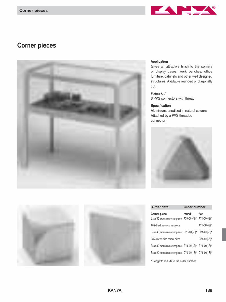
ApplicationGives an attractive finish to the corners of display cases, work benches, office furniture, cabinets and other well designedstructures. Available rounded or diagonallycut.
Fixing kit*3 PVS connectors with thread
SpecificationAluminium, anodised in natural coloursAttached by a PVS threaded connector
Order data Order number
Corner piece round flatBase 50 extrusion corner piece A70–00(–S)* A71–00(–S)*
A02–8 extrusion corner piece A71–08(–S)*
Base 40 extrusion corner piece C70–00(–S)* C71–00(–S)*
C02–8 extrusion corner piece C71–08(–S)*
Base 30 extrusion corner piece B70–00(–S)* B71–00(–S)*
Base 20 extrusion corner piece D70–00(–S)* D71–00(–S)*
*Fixing kit: add –S to the order number

KANYA140 KANYA140
Handles
ApplicationA modern looking, ergonomic handle (mainly used on 20 and 30 base extrusions).
SpecificationPA-GF, black
Colours of covers:dark grey, grey, yellow, orange, blue, red
ApplicationFor inset, sliding doors etc. This offsethandle ensures no trapped fingers.
SpecificationBlack aluminium RAL 9005 (plastic coated)Natural anodised aluminium
Order data Order number
Ergo handle D65–01 + colourof cover
Order data Order number
handle black anodisedA65–05 A65–06
Cover (detachable)
Measurement data
Handle A B C D H T Ø øsmall 17 21 74 93.5 36 6 10.5 6.5medium 122 19 82 100 33 13 8.5 5.5large 134 26 95 117 41 6.5 13.5 8.5
Handles
ApplicationHighly versatile. Two sizes are availablefrom standard stock. Fixed in place fromthe inside or outside using M5/8 screws.
SpecificationPA-GF, black
Order data Order number
Small handle B65–00Medium handle B65–01Large handle A65–01

KANYA 141
Tube handels
Tube handle offset Tube handle straight
Order data Order number
Ltube handle offset 250mm A65–22tube handle offset 300mm A65–23tube handle offset 400mm A65–24tube handle offset 500mm A65–25Other length on customers requirement available
Order data Order number
LTube handle straight 250mm A65–12Tube handle straight 300mm A65–13Tube handle straight 400mm A65–14Tube handle straight 500mm A65–15Other length on customers requirement available
ApplicationThese strong tubing grasps are suitablefor heavy sliding doors, large windows oralso as impact handles for trolleys.
With double sliding doors and critical space conditions, anywhere that risk oftrapping hands exists, the offset tubinggrasp is highly recommended.
SpecificationSupport: PA-GF, blackTube: Al, anodised
SpecificationSupport: PA-GF, blackTube: Al, anodised

KANYA142
Ball catches / Magnetic fasteners
Magnetic fasteners
Order data Order number
Duo magnetic catch A67–20
ApplicationThis magnetic catch is highly adaptable.You can choose between two retentionforces, depending on your requirements.The elongated holes also permit a largeadjustment range.
SpecificationBlack plastic with a permanent magnet /pan-head screw with nut.
Ball catches
Order data Order number
Small ball catch A66–00Large ball catch A66–10
Ball catches
Order data Order number
Ball catch A66–50Spacer A66–54
ApplicationThe ball catches are used as an adjust-ment of sliding and swing doors and areideal for mounting of movable compo-nents. For the ball catch A67–20 are spa-cers of 4 mm thickness available.
SpecificationBrass (chromium-plate steel balls)
SpecificationPA-GF, blackfixing screw: steel zinc coated
Spacer
KANYA 143
Order data Order number
L = 18 L = 30Quick-release fastenerwith a wing pin A64–10(–S)* A64–11(–S)*Quick-release fastenerwith a slotted pin A64–20(–S)* A64–21(–S)*
* Fixing kit: add –S to the order number
Wing pin
Slotted pin
Handle strip / Arrester plate / Quick-release fastener
Quick-release fasteners
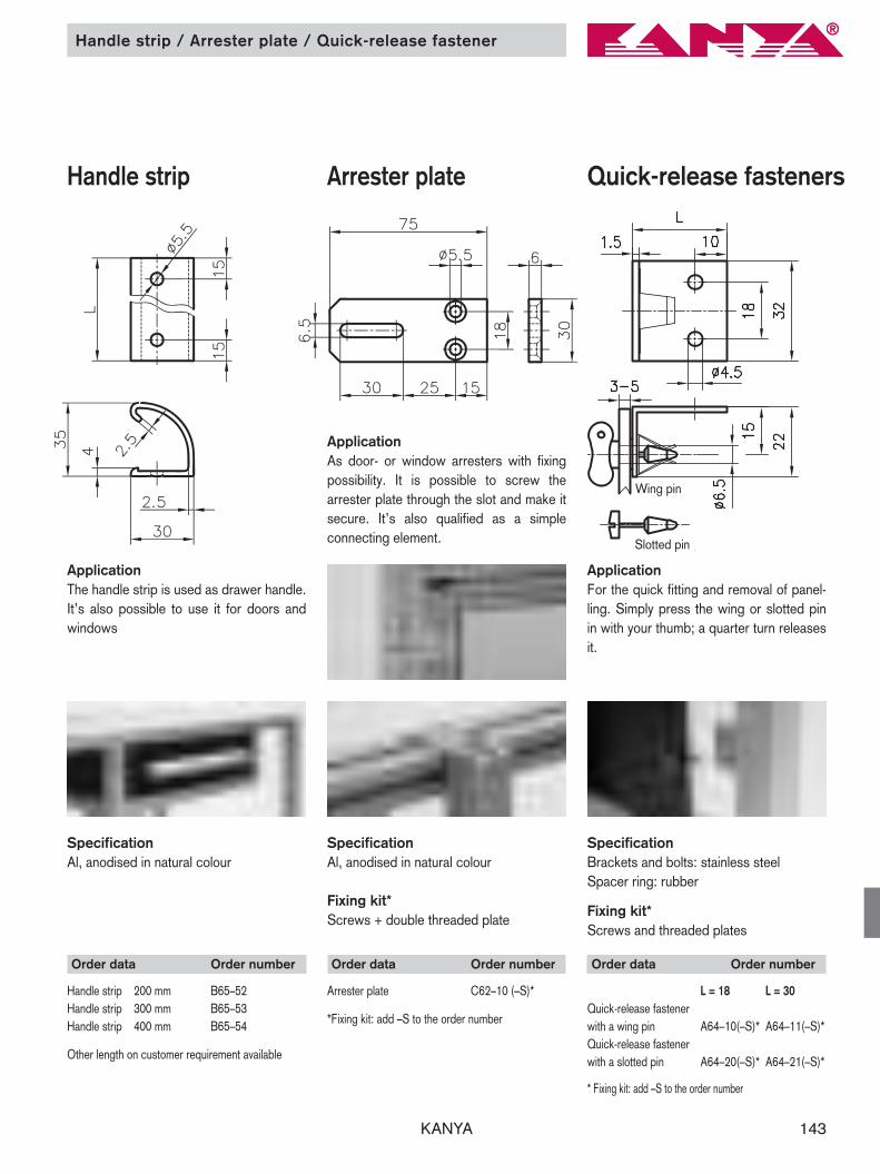
ApplicationFor the quick fitting and removal of panel-ling. Simply press the wing or slotted pinin with your thumb; a quarter turn releasesit.
SpecificationBrackets and bolts: stainless steelSpacer ring: rubber
Fixing kit*Screws and threaded plates
Arrester plateHandle strip
SpecificationAl, anodised in natural colour
Fixing kit* Screws + double threaded plate
SpecificationAl, anodised in natural colour
Order data Order number
Arrester plate C62–10 (–S)*
*Fixing kit: add –S to the order number
Order data Order number
Handle strip 200 mm B65–52Handle strip 300 mm B65–53Handle strip 400 mm B65–54
Other length on customer requirement available
ApplicationAs door- or window arresters with fixingpossibility. It is possible to screw the arrester plate through the slot and make itsecure. It’s also qualified as a simpleconnecting element.
ApplicationThe handle strip is used as drawer handle.It’s also possible to use it for doors andwindows
KANYA144
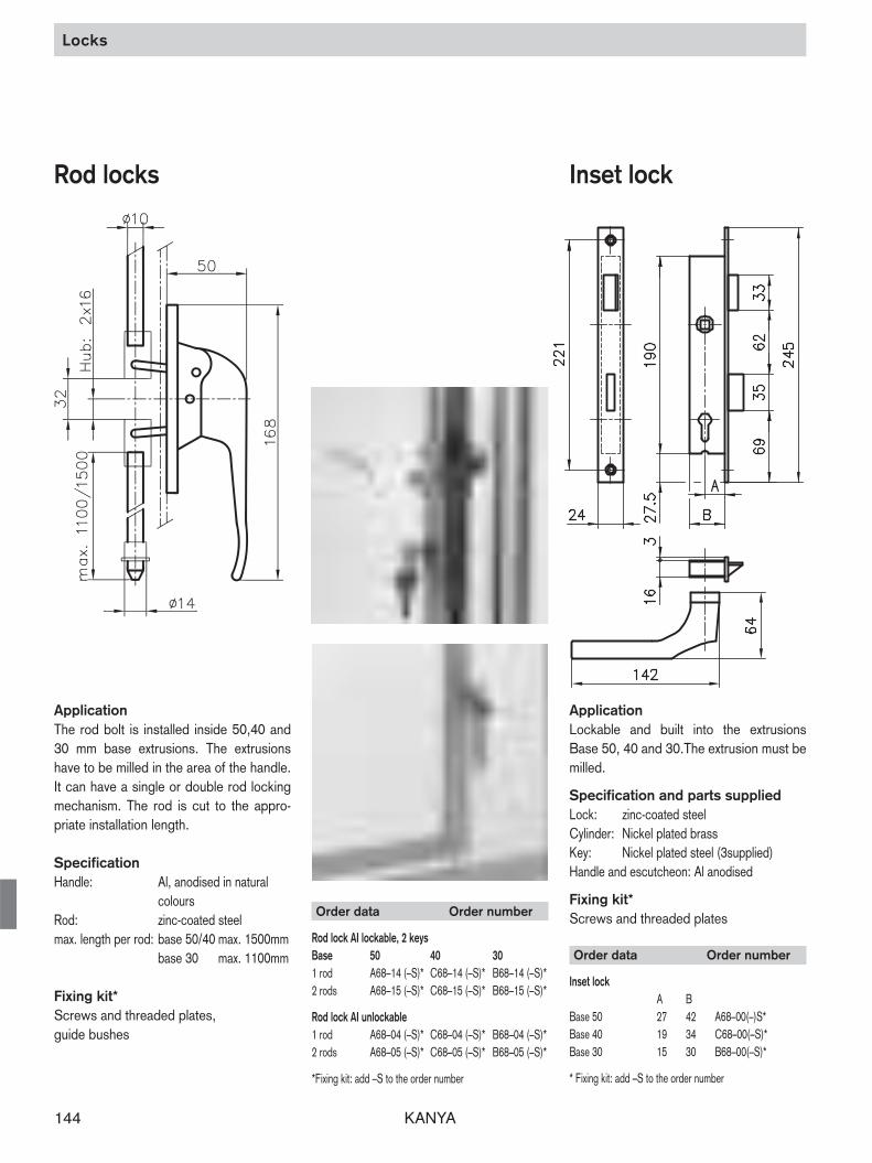
Locks
Order data Order number
Inset lock A B
Base 50 27 42 A68–00(–)S*Base 40 19 34 C68–00(–S)*Base 30 15 30 B68–00(–S)*
* Fixing kit: add –S to the order number
ApplicationLockable and built into the extrusionsBase 50, 40 and 30.The extrusion must bemilled.
Specification and parts suppliedLock: zinc-coated steelCylinder: Nickel plated brassKey: Nickel plated steel (3supplied) Handle and escutcheon: Al anodised
Fixing kit* Screws and threaded plates
Rod locks Inset lock
ApplicationThe rod bolt is installed inside 50,40 and30 mm base extrusions. The extrusionshave to be milled in the area of the handle.It can have a single or double rod lockingmechanism. The rod is cut to the appro-priate installation length.
Specification Handle: Al, anodised in natural
coloursRod: zinc-coated steelmax. length per rod: base 50/40 max. 1500mm
base 30 max. 1100mm
Fixing kit* Screws and threaded plates, guide bushes
Order data Order number
Rod lock AI lockable, 2 keysBase 50 40 30 1 rod A68–14 (–S)* C68–14 (–S)* B68–14 (–S)* 2 rods A68–15 (–S)* C68–15 (–S)* B68–15 (–S)*
Rod lock AI unlockable1 rod A68–04 (–S)* C68–04 (–S)* B68–04 (–S)*2 rods A68–05 (–S)* C68–05 (–S)* B68–05 (–S)*
*Fixing kit: add –S to the order number
KANYA 145
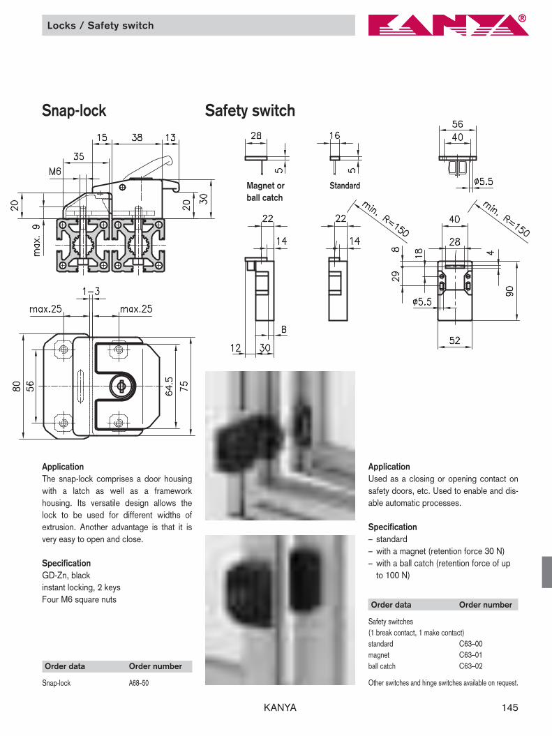
Locks / Safety switch
ApplicationUsed as a closing or opening contact onsafety doors, etc. Used to enable and dis-able automatic processes.
Specification– standard– with a magnet (retention force 30 N)– with a ball catch (retention force of up
to 100 N)
Safety switch
Order data Order number
Safety switches(1 break contact, 1 make contact)standard C63–00magnet C63–01ball catch C63–02
Other switches and hinge switches available on request.
Magnet or ball catch
Standard
Snap-lock
ApplicationThe snap-lock comprises a door housingwith a latch as well as a framework housing. Its versatile design allows thelock to be used for different widths of extrusion. Another advantage is that it isvery easy to open and close.
SpecificationGD-Zn, blackinstant locking, 2 keysFour M6 square nuts
Order data Order number
Snap-lock A68–50
KANYA146
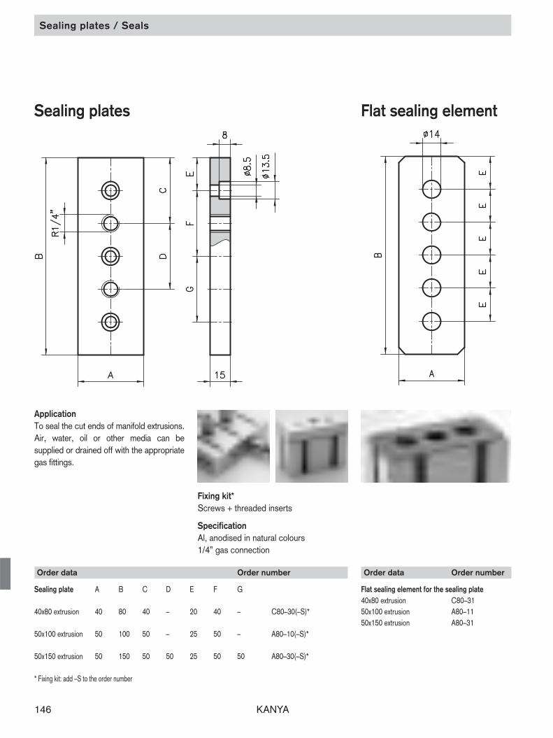
Sealing plates / Seals
ApplicationTo seal the cut ends of manifold extrusions.Air, water, oil or other media can be supplied or drained off with the appropriategas fittings.
Fixing kit*Screws + threaded inserts
SpecificationAl, anodised in natural colours1/4” gas connection
Sealing plates
Order data Order number
Sealing plate A B C D E F G
40x80 extrusion 40 80 40 – 20 40 – C80–30(–S)*
50x100 extrusion 50 100 50 – 25 50 – A80–10(–S)*
50x150 extrusion 50 150 50 50 25 50 50 A80–30(–S)*
* Fixing kit: add –S to the order number
Flat sealing element
Order data Order number
Flat sealing element for the sealing plate40x80 extrusion C80–3150x100 extrusion A80–1150x150 extrusion A80–31

KANYA 147
Sealing washer / Junction plates
Sealing washer Junction plates
ApplicationHigh pressure junction plate for sideconnections (> 6 bar). The thread for thejunction is normally tapped directly into theside of the extrusion. No junction platesare required for side connections to the40x80 extrusion.Fixing kit*Screws + threaded platesSpecificationAl, anodised in natural colours1/4” gas connection
Order data Order number
Junction plate A B C D E F G
50x100 extrusion 50 100 50 – 25 50 – A80–40(–S)*
50x150 extrusion 50 150 50 50 25 50 50 A80–50(–S)*
* Fixing kit: add –S to the order number
Order data Order number
Junction plate sealing washer50x100 A80–4150x150 (2 x) A80–42
ApplicationThe flat seal between the sealing plate and the extrusion end or a sealing washerbetween the junction plates and the sideof the extrusion guarantees a seal up to 6 bar.
Specification Black nitrile rubber70 shore A

KANYA148
Shaft clamping block
Shaft clamping block
ApplicationA high-precision linear bearing system can be created very easily with the components, i.e. the shaft clamping block,the linear bearing block and the steelshaft. As there are two different shaftclamping blocks, the system can be assembled flexibly. The fixing centrescombine well with the PVS extrusions.
SpecificationAluminium, anodised in natural colours
Order data Order number
Shaft clamping block – straight L16–60Shaft clamping block – 90° L16–65
Shaft clampingblock – straight
Shaft clampingblock – 90°

KANYA 149
Linear bearing block / Steel shafts
Linear sliding block
Order data Order number
Linear sliding block L16–68
Steel shafts
SpecificationSteel, Cf 53, hardened, groundHardness: HRc 62 ± 2
ApplicationThe steel shafts are used in combinationwith the linear sliding block and the shaft clamping blocks assembled on the appropriate extrusion framework. Thisserves to create high load-bearing linearguides.
Order data Order number
Steel shaft ø12Standard length 6000 mm L12–20–01/6000Cut to length L12–20–02–02/…
Steel shaft ø16Standard length 6000 mm L16–20–01/6000Cut to length L16–20–02–02/…
Load rating
dynamic static850 N 620 N
SpecificationHousing: aluminium, anodised in naturalcoloursLinear bearing: steel, sealed on both sides,maintenance-free
Bearing seat for shafts of ø 16–h6
Dowel hole

KANYA150
Shaft clamping extrusion
Shaft clamping extrusions
ApplicationShaft clamping extrusion complete withsteel shafts Cf 53, hardened, ground andwith fixing kit.
Order data Order number
Steel clamping extr., compl. 50 mm baseStandard length 6000 mm L12–06–00/6000Cut to length L12–06–02–02/...
Steel clamping extr., compl. 100 mm baseStandard length 6000 mm L16–06–00/6000Cut to length L16–06–02–02/...
Order data Order number
Shaft clamping extrusion 50 mm baseStandard length 6000 mm L12–05–00/6000Cut to length L12–05–02–02/…
Shaft clamping extrusion 100 mm baseStandard length 6000 mm L16–05–00/6000Cut to length L16–05–02–02/…
ApplicationThe steel shafts are fixed firmly to theBase 50/100 extrusion using the shaftclamping extrusion. They can be combined with the slide plates and rollersas a simple way to create linear slides tomove very high loads.
SpecificationAluminium, matt, anodised in natural colours

KANYA 151
Order data Order number
Shaft support extrusion 40x100Standard length 6100 mm L16–10–00/6000
Shaft support extrusion 40x100Cut to length L16–10–02/…
Extra machining Pages 34/35
Technical data
Ix = 172.22 cm4
Iy = 31.92 cm4
Wx = 33.83 cm3
Wy = 15.95 cm3
Cross section area = 16.75 cm2
Weight = 4.5 kg/m
Order data Order number
Shaft clamping extrusions two-partStandard length 6000 mm L16–01–00/6000Cut to length L16–01–02–02/…
Shaft clamping extrusion / Shaft support extrusion
Shaft support extrusiontype L16–10
ApplicationFor simpler linear slides, ø 16 steel shaftscan be easily clipped into Base 40 or 50extrusion using the two-part shaft clamping extrusion. The guide extrusion 40x100 is used forhigh load linear slides. Centreline distancebetween upper and lower shafts is decided by the customer’s load carrying requirement.
SpecificationAluminium, matt, anodised in natural colours

KANYA152
for roller shield L16
Messurement data
Slide plate for use with shaft clamping extrusionBase A B C D E F G H M s Ø ø Weight50 150 130 110 89 60 60 30 30 8 12 12 10 0.6 kg100 300 240 200 158 100 100 50 50 8 15 20 17 2.9 kg
Slide plate for use with two part shaft clamping extrusionProfile A B C D E F G H M s Ø ø Weight50x150 350 310 250 233 150 150 75 75 8 15 *20 17 4.3 kg40x160 350 320 250 243 150 150 75 75 8 15 *20 17 4.5 kg
Loading and moments
static [N/Nm] dynamic [N/Nm]Fy Fz Mx My Mz Fy Fz Mx My Mz3000 1920 35 55 90 3000 1200 22 34 907200 3400 105 160 600 7200 2100 65 100 600
7200 2500 130 190 800 7200 1500 90 120 8007200 2500 135 195 850 7200 1500 90 120 850
ApplicationThe required linear slide arrangementis completed by use of the sliding plate. The sliding plate is designed towithstand exceptionally heavy loading.
SpecificationRaw aluminium
Order data Order number
Slide plate for use with shaft clamping extrusionBase 50 L12–30Base 100 L16–31Slide plate for use with two part shaft clamping extrusion50x150 extrusion L16–3540x160 extrusion L16–34
acc. to customer’s drawing L12–39acc. to customer’s drawing L16–39
Slide plates acc. to customer drawing
Slide plates
Slide plates
* The Ø20 equates to the Ø ofthe retainer of the bolts (distancebushes)

KANYA 153
Eccentric bolts
Rollers / Roller shield
Messure data Load rating
D A B E H L1 L2 M R Ø ø Weight dyn. stat.ø12 21.75 15.9 0.75 5 29 45 M10x1.5 17.5 12 10 0.15 kg 8400 N 5000 Nø16 31.5 22.6 1.0 8 44 67 M16x1.5 26 20 17 0.42 kg 16800 N 9500 N
Order data Order number
Roller for bar Ø12 centric eccentricL = 14 L12–25 L12–26
Roller for bar Ø16 L = 18.5 L16–25 L16–26L = 21.5 L16–21 L16–22L = 26.5 L16–27 L16–28
Rollers Roller shield
Order data Order number
Roller shield L16–40 Rollershield complete L16–45
Application For use with the slide plates, to do a linea-er guide-rail.
Specification Roller: steel 100 Cr6, hardened, grindednut and ground bolt and spacer bush:black steel
ApplicationBoth to guard the roller and ect as a grea-se scraper
SpecificationPA-GF, black
Parts supplied shield complete 1 roller shield 2 grease scrapers1 set of fixing materialsWeight: 0.15 kg

KANYA154
Accessories for linear guides
Application As a spacer for the roller shield to adjustthe different sizes of the rollers.
Specification Aluminium, raw
Application The support fits on the slide plate base 50.Together with the oil scraper the slide fora small linear guide is complete.
Specification Aluminium, anodised in natural colours
Application The oil scraper is for two functions. Onone hand, it cleans the steel bars and onthe other it coat the steel bars with a oilfilm to protect it from rusting.
Specification Shield: PA-GF grease scraper: oil-impregnated felt
Spacer for the rollershield
Oil scraperOil scraper support
Order data Order number
Spacer L16–40–04
Order data Order number
grease scraper L16–46grease scraper L12–46
Order data Order number
Support for oilscraper L16–43

KANYA 155
Accessories for linear guides
ApplicationThe end stopper in combination with thebuffer is normally screwed on the end ofthe extrusions base 50, serving as a stopfor the linear guides.
Specification Aluminium, anodised in natural colours
ApplicationFor use as an end stop for linear guides
Specification rubber, highly deformable
End stop Buffer
Order data Order number
End stop 50 L16–55End stop 100 L16–53
Order data Order number
Buffer L16–50

KANYA156
Special tools

KANYA 157
Special purpose tools
Drill jig and special drill bits
Order data Order number
Drill jig50/40/30 base AB95–0
Special drill bitsto fit the drill jig50/40 base A96–130 base B96–2A02–8, C02–8, C03–8 extrusions A96–3B01–8 extrusion B96–3
Machining data
Extrusion type D A1 A2 T50 base 18.1 25 32 3340 base 18.1 25 32 2830 base 15.1 25 32 2220x47/95/150 base 15.1 25 32 1820x20/40 base 7.3 25 25 –
Standard 90° joint"25" stop
ApplicationThe drill jig and special drill bits make it easy to drill the holes for KANYA’s patented PVS connector. The main advantage of the drill jig is that it clampsdirectly onto the extrusion. The rotatingstop, for square or mitred cuts, guaranteesthe precise drilling distance.The HSS special drill bit, with the MT2 Morse taper shank, is ground flat to cut the extrusion surface. It can be re-sharpened as often as necessary.A special drill bit with a 90° point is usedto drill the C03–8, B01–8 softline extru -sion and the A02–8 and C02–8 angle ex-trusions.
Mitre joint"32" stop
NoteThe 7.3 mm Ø holes for 20x20/40 extrusi-ons are drilled using a normal twist drill bitwithout a drill jig.

KANYA158
Punch cutter
Punch cutter PVS®-EASY Multi-purpose toolPVS®-EASY
ApplicationWith the punch cutter its possible to breakout a part of the slot of the «EASY»-extru-sions to insert the Allen-key into the slot tofix the connector. The tool is sliding in theslot of the extrusion from the cut side Theadjustable stop gives the right position onthe extrusion.
Application With the multi-purpose tool you can parti-ally break the slot and then insert theAllen-key at that position. The Allen key isthen used to assemble the connector. Thetool is very simple, and not comparablewith the punch cutter.
Order data Order number
Punch cutter PVS®-EASY E96–1
Order data Order number
Multi-purpose tool PVS®-EASY E96–5

KANYA 159KANYA
Allen Key
Order data Order number
Allen key set E97–5SW 1,5 – 10
SW = wrench size
Order data Order number
KANYA-Allen key SW 6 short E97–1KANYA-Allen key SW 6 long E97–2
Allen key setSW 1,5 –10
KANYA-Allen key SW 6
Application For allen screws.
The ball at the end allows it to screw intoangular positions with the allen key.
This is necessary for the new function ofthe patent PVS®-EASY connectors.

KANYA160
Get the KANYAConstruction kit for your CADsystem!
The KANYATHEK3D software not only offers you the complete productdetails for your CAD system, but alsothe possibility to edit the extrusionsand much more.
Get the KANYA product library construction kit directly from the CD-ROM onto your CAD system. Thesoftware generates all the KANYA products in all common CAD formats.Direct interfaces are available for aconstantly growing number of 2D- and3D-CAD systems.
Edit extrusions and other products withyour own inputs using KANYATHEKand afterwards load them on your CADor simply generate the parts list automatically for your electronic order.
A unique KANYA service.
Library of products and design software

KANYA 161
®
Library of products and design software
The installation and application of the KANYATHEK software on your computer is simple and problem-free. In addition ,a monitoring func-tion automatically checks for the availability of updates or interesting news on KANYA whenever you start up KANYATHEK. You thenchoose if you would like to receive the information and updates.
Application You choose the required product and edit it virtually according to the requirements. Afterwards you can export the configured elementonto your CAD system and transfer the required amount to the order parts list. You can save the parts list anytime and use it on de-mand. Based on the precise product number and process coding, the parts list can be audited at anytime and transferred to us at thetouch of a button.
– Product library and design software
System requirements Windows 2000, Windows XP, Windows Vista; Microsoft .NET Framework 1.1; at least 256 MB RAM; at least 200 MB free hard discand at least 256 colors (1024 x 768 Pixel)
1. Product choice
The KANYATHEK and its advantages – Significant reduction in design time. – Safe electronic order release via the automatically generated parts list. – All KANYA elements are available as models.– Simple and logic layout- no special prior knowledge necessary. – Your KANYA documents are always up-to-date.
2. Editing extrusion
3. Generate parts list

KANYA162
Index
19“ auxiliary extrusion, 30 mm base 8119“ auxiliary extrusion, 50 mm base 81
AAcrylic glass 134Allen key set 159Al-heavy duty hinges fixed type 137Aluminium hinges lift-off type 136Aluminium filler strip 126Aluminium sheets 132Angle extrusion 25x35 86Angle extrusion 31x31 86Angle extrusion 38x38 86Angle extrusion 40x45° 53Angle extrusion 50x45° 39Angle extrusion 60x120 86Angle extrusion 60x60 87Angle extrusion 70x70 87Angle extrusion 100x100 87Anti-twist spigots 112Arrester plate 143Attachment bracket 109
BBall catches 142Base extrusion 20x20 74Base extrusion 20x40 75Base extrusion 30x100 72Base extrusion 30x30 82Base extrusion 30x50 68Base extrusion 30x60 70Base extrusion 40x40 49Base extrusion 40x80 54Base extrusion 50x50 37Base extrusion 50x100 41Base extrusion 60x60 70Base extrusion 80x80 59Base extrusion 100x100 44Base plates 116Beam extrusion 40x120 56Beam extrusion 40x160 57Beam extrusion 50x150 46Beam extrusion 80x120 60Box frame extrusion 20x40 76Box frame extrusion 20x47 76Box frame extrusion 20x95 77
Box frame extrusion 30x95 82Buffer 155
CCable ducts 124Cable ties 125Castors 119Channel reducing strip 127Channel reducing strips and filler strips 128Clamping block 107Clamping block 108Clamping extrusion 16x29 84Clamping nuts 111Clamping sealing strip 131Composite panels 133Corner extrusion 30° 66Corner extrusion 45° 66Corner extrusion 45° 52Corner extrusion 60° 67Corner extrusion 20x20 74Corner extrusion 30x30 64Corner extrusion 40x40 50Corner extrusion 50x50 38Corner extrusion with panel slots 30x30 64Corner extrusion with rip off slots 40x40 51Corner pieces 139Covering cap for PVS-connector 96
DDoor sealing strip 130Double bolting bracket 117Double clamping extrusion 16x50 84Double face extrusion 30x30 65Double face extrusion 40x40 50Double face extrusion 50x50 39Double extrusion nuts 111Double threaded plates 110Double trolley 121Drill jig and special drill bits 157
EElectrically conductive leveling feet 115Enclosure panels 132
Term Page Term Page Term Page
End caps 126End stop 155Expanded metal 132Expansion sleeves 102Extrusion nuts 111
FFace extrusion 20x150 77Face extrusion 20x20 74Face extrusion 20x40 75Face extrusion 30x30 63Face extrusion 30x50 68Face extrusion 30x300 73Face extrusion 40x40 49Face extrusion 40x80 55Face extrusion 50x50 38Face extrusion 50x100 43Face extrusion with panel slots 30x30 63Face extrusion with panel slots 30x50 69Face extrusion with panel slots 30x60 69Face extrusion with panel slots 30x100 72Face extrusion with rip off slots 40x40 51Face extrusion with rip off panel slots 50x50 40Flange plates 102Flat sealing element 146Floor bolting bracket 116Foot plates 116Four sided extrusion 40x40 52Full-plastic panels 134
GGrid extrusion 131
HHalfround threaded plates 110Hammer nuts 112Hand rail extrusion 50x50 78Handle strip 143Handle strip extrusion 88Handles 140Heavy duty extrusion 100x100 45Heavy duty extrusion 30x30 62Heavy duty extrusion 50x100 42Heavy duty extrusion 50x50 37Heavy duty extrusion 80x160 61
KANYA 163
Index
Term Page Term Page Term Page
Heavy duty extrusion 100x200 47Hinge extrusion, type A 88Hinge extrusion, type B 88Hinge extrusion, type C 88H-strip 128
IInset lock 144Installation rings 125
JJoint 138Joints with clamp lever 138Junction plates 147
KKANYA-Allen key 159Kanyathek 161
LL-shaped extrusion 80x80x40 58Leg bolt-down socket 118Leveling feet 114Leveling feet with shock absorbers 115Light extrusion nuts 111Light extrusion 40x80 54Light extrusion 40x120 55Light extrusion 50x50 36Lightweight extrusion 30x30 62Lightweight extrusion 40x40 48Lightweight extrusion 80x80 59Linear sliding block 149
MMagnetic fasteners 142Micro chipboard 133Mounting bracket and dowel 107Mounting brackets 106Multi-purpose tool PVS-EASY 158
NNon-swivel castors 119
OOctagonal extrusion, 20 mm base 76Octagonal extrusion, 30 mm base 71Oil scraper 154Oil scraper support 154
PPanel clamp extrusion 13.5x50 85Plastic hinges fix 136Plastic hinges lift-off type 136Plastic slide extrusion 122Polycarbonate 134Punch cutter PVS-EASY 158PVC filler strips 127PVS connectors 92–95 PVS light 101PVS-EASY 99
QQuick-release fasteners 143
RRectangular tube 89Retaining clips 125Rhomboid nuts 112Rod locks 144Roller shield 153Roller-mounted support 121Rollers, plastic 120Rollers, steel 153Runner extrusion 30x30 83Runner extrusion 30x50 83
SSafety-edge extrusion 130Safety switch 145Sealing plates 146Sealing washer 147Semi-circular sealing strip 130Shaft clamping block 148Shaft clamping extrusions 150Shaft support extrusion 151Single bolting bracket 117Slide plates 152Sliding hook 123
Slot extrusion 20x80 79Slot extrusion 20x120 79Snap-lock 145Softline extrusion 20x20 75Softline extrusion 30x30 65Softline extrusion 40x40 53Spacer for the roller shield 154Special extrusion 80x80 78Special hinges lift-off type 137Steel shafts 149Steel wire mesh 135Super lightweight extrusion 40x40 48Super lightweight extrusion 30x30 62Support extrusion11x30.5 85Supporting extrusion 129Suspended guard fittings 135
TT-bolts 109Threaded inserts 113Threaded plates 110Triple channel extrusions 30x15 80Tube handle offset 141Tube handle straight 141
UU-clamping extrusion 8x13.5 85U-sealing strip 131Uniblock 108
WWall rail 50x18 80Wedge extrusion 129
ZZn-diecasting hinges fixed type 137
KANYA164
BestillingOrder sheet
■ Order■ Inquiry
Company:
Contact:
Street:
ZIP code/place:
Phone:
Fax:
E-Mail:
Order number:
Commission:
Delivery time:
Billing address:
Send to:
Fax:
E-Mail:
Pos.-No. Product-No. Term Quantity Notice
Project description:

KANYA 165
Sketch

KANYA166
NotizenNotes

KANYA 167
Notes

KANYA168
J
NL
PL
RU
VENTOR SICHERHEITSSYSTEME –AUTOMATISIERUNGFalkenau 11A-4690 SchwanenstadtTel: 0043 (0)7673 80511-0Fax: 0043 (0)7673 80511-40e-mail: [email protected]: http://www.ventor.at
MAM S.A.Industrie/AutomationRue de la Station 9– 11B-1435 Mont St. GuibertTel: 0032-10/657 012Fax: 0032-10/658 791e-mail: [email protected]
ABG – INDUSTRIA COMERCIO LTDA.Av. das Araucárias, 509 – BarigüiCEP 83707-000Araucária-Paraná-BrasilTel: 0055-41/643 1384Fax: 0055-41/643 3628e-mail: [email protected]: http://www.kanya.com.br
VISIMPEX a.s.Seifertova 33CZ-750 02 P`́rerovTel: 00420 581/808 134Fax: 00420 581/808 505e-mail: [email protected]: http://www.kanya.cz
Nord PLZ 1,2,3,4,5DRECKSHAGE GMBH & CO. KGWalter-Werning-Straße 7D-33699 BielefeldTel: 0049-521/92 59-0Fax: 0049-521/92 59 289e-mail: [email protected]: http://www.dreckshage.de
Süd PLZ 0,6,7,8,9KANYA DEUTSCHLAND GMBHMeußelsdorferstraße 25D-95615 MarktredwitzTel: 0049-9231/603 860Fax: 0049-9231/603 861e-mail: [email protected]: http://www.kanya-deutschland.de
MIWA CO. LTD.No. 632, SEKO 2-chomeMoriyama-kuJ-Nagoya 463 0068Tel: 0081-52/795 60 11Fax: 0081-52/795 33 66e-mail: [email protected]: http://www.miwa-inc.co.jp
TEVEL COMPONENTS BVEndepoelstraat 4NL-6942 GL DidamTel: 0031-(0)316/342 815Fax: 0031-(0)316/343 086e-mail: [email protected]: http://www.tevel.nl
TABAL Sp. J.ul. Energetyków 14PL-20-468 LublinTel: 0048-(0)81/749 09 11Fax: 0048-(0)81/749 01 28e-mail: [email protected]: http://www.tabal.pl
SERVOTECHNICA ZAO22, Vyborgskaya str.125130 Moscow, RussiaTel: 0007 495/797 8866Fax: 0007 495/450 0043e-mail: [email protected]: http://www.servotechnica.ru
EIE MASKIN ABVassgatan 3S-41502 GöteborgTel: 0046-31/707 48 00Fax: 0046-31/19 52 55e-mail: [email protected]: http://www.eie.se
A-LINE CORPORATION1303 Upper Asbury AveCharlotte NC 28206 – USATel: 01-704/332-1059Fax: 01-704/332-4729e-mail: [email protected]: http://www.aline1.com
KANYA-Messebau-Partner weltweitLüdemann & Co.Internationaler MessebauGilcherweg 21D-22851 NorderstedtTel: 0049-40/524 3405Fax: 0049-40/524 3258
JJ MEKANIK ASIndustriparken 17DK-4450 JyderupTel: 0045-59/25 81 00Fax: 0045-59/25 81 01e-mail: [email protected]: http://www.jjmekanik.dk
IBALTEC SISTEMAS, S.L. C/. Josep Soler, 74-76 bjs.E - 08310 ARGENTONA (Barcelona) Tel: 0034-93/756 11 53Fax: 0034-93/797 40 34 e-mail: [email protected]: http://www.ibaltec.com
BERNAY AUTOMATION S.A.B.P. 451-1, Rue de MennevalF-27304 Bernay CedexTel: 0033-232/473 510Fax: 0033-232/430 188e-mail: [email protected]: http://www.bernay-automation.com
THINKING SPACE SYSTEMS Ltd.Unit 2, The QuadrangleAbbey Park Industrial EstateRomseyHampshire SO51 9DL, UKTel: 0044-(0)1794/51 66 33Fax: 0044-(0)1794/51 66 32e-mail: [email protected]: http://www.kanya-uk.co.uk
TECNO-CENTER S.R.L.C.so Lombardia, 41I-10078 Venaria Reale (TO)Tel: 0039-011/455 11 21Fax: 0039-011/455 75 95e-mail: [email protected]: http://www.tecno-center.it
CONLOG LTD.7 Leshem St.P.O. Box 3571IL-Petach-Tikva 49134Tel: 00972-3/926 95 95Fax: 00972-3/923 33 67e-mail: [email protected]: http://www.conlog.co.il
A
B
BR
CZ
D
USA
S
ESP
F
GB
I
�
DK
ILD
KANYA-Vertretungen / Weitere KANYA-ProdukteIndex alphabétiqueIndex Sakregister
Headquaters • KANYA AG/SA/Ltd. • Neuhofstrasse 9 • CH-8630 RütiTel. ++41-(0)55/251 58 58 • Fax ++41-(0)55/251 58 68 • e-mail: [email protected] • Internet http://www.kanya.com
KANYA Worldwide