1394 open host controller interface specificationthe open hci 1.0 specification was developed using...
TRANSCRIPT

1394Open Host Controller Interface
Specification
Release 1.1January 6, 2000
Copyright © 1996-2000 by the Promoters of the 1394 Open HCI.

1394 Open Host Controller Interface Specification / Release 1.1 Printed 1/10/00
Page ii Copyright © 1996-2000 All rights reserved.

PREFACE 1394 Open Host Controller Interface Specification / Release 1.1 Printed 1/10/00
t
t
s.e-
PREFACE
Notice
THIS SPECIFICATION IS PROVIDED "AS IS" WITH NO WARRANTIES WHATSOEVER, INCLUDING ANYWARRANTY OF MERCHANTABILITY, NONINFRINGEMENT, FITNESS FOR ANY PARTICULARPURPOSE, OR ANY WARRANTY OTHERWISE ARISING OUT OF ANY PROPOSAL, SPECIFICATION ORSAMPLE. Apple Computer, Inc., Compaq Computer Corporation, Intel Corporation, Microsoft Corporation,National Semiconductor Corporation, Sun Microsystems, Inc., and Texas Instruments, Inc. disclaim all liability,including liability for infringement of any proprietary rights, relating to use of information in this specification. Nolicense, express or implied, by estoppel or otherwise, to any intellectual property rights is granted herein. Excepthat a license is hereby granted to copy and reproduce this specification for internal use only. *Third-party brandsand names are the property of their respective owners.
Copyright © 1996-2000 All Rights Reserved. Apple Computer, Inc., Compaq Computer Corporation, IntelCorporation, Microsoft Corporation, National Semiconductor Corporation, Sun Microsystems, Inc., and TexasInstruments, Inc.
Intellectual Property
Implementation of this Specification is governed by the terms of the 1394 Open Host Controller Interface PatenLicense Agreement.
This specification may contain and sometimes even require the use of intellectual property owned by otherRights to such intellectual property are not conveyed except as provided by the 1394 Open HCI Promoters agrement and the 1394 Open HCI Adopters agreement.
Information
An on-line copy, updates, and notices regarding this specification will be maintained on the following web sites:
http://developer.intel.com/technology/1394/specs.htm
http://www.microsoft.com/hwdev/1394/#Specs
Questions, comments, and issues concerning this document should be directed to the 1394 Open HCI reflector: [email protected]
Copyright © 1996-2000 All rights reserved. Page iii

PREFACE 1394 Open Host Controller Interface Specification / Release 1.1 Printed 1/10/00
Specifi-
original
4 Opener, Jerryers, Erik
Promoters
The Promoters of record on January 6, 2000, the date of publication of the 1394 Open Host Controller Interfacecation, Release 1.1, are:
Apple Computer, Inc.Compaq Computer CorporationIntel CorporationMicrosoft CorporationNational Semiconductor CorporationSun Microsystems, Inc.Texas Instruments, Inc.
Contributors
The Open HCI 1.0 specification was developed using Apple Computer’s Pele design as a starting point. The Pelecontributors were Jim Baldwin, Kevin Christiansen, Nikhil Jayaram, Michael Johas Teener and Rahoul Puri. The Editor of the 1394 Open HCI specification up through Draft 0.7, was Michael Johas Teener.
This specification is a derivative of the 1394 Open Host Controller Interface specification Release 1.00. The 139HCI Release 1.00 key contributors were Eric W. Anderson, Richard Baker, Joe Bennett, Mike Eneboe, John FullHauck, Diana Klashman (Editor), Robert Macomber, Rahoul Puri, Michael Johas Teener, Peter Teng, Scott SmyStaats, Lee Wilson, (Chair), and David Wooten.
The following is a list of key contributors to the 1394 Open Host Controller Interface Release 1.1 specification.
Lee Wilson, ChairSteve Bard, Co-Vice-ChairJohn Fuller, Co-Vice-Chair
Neil Morrow, Editor
Eric W. AndersonRichard BakerDavid Hunter
Diana KlashmanRobert MacomberMike Musciano
Peter TengDavid Wooten
Page iv Copyright © 1996-2000 All rights reserved.

Table of Contents 1394 Open Host Controller Interface Specification / Release 1.1 Printed 1/10/00
i
iii
v
i
i
1
Table of Contents
PREFACE ............................................................................................................................................................................ ii
Notice .............................................................................................................................................................................. iiIntellectual Property ........................................................................................................................................................ iiInformation ..................................................................................................................................................................... iiPromoters ................................................................................................................................................................. ivContributors .................................................................................................................................................................... iv
Table of Contents .................................................................................................................................................................
List of Figures ................................................................................................................................................................... xii
List of Tables .....................................................................................................................................................................xvi
1. Introduction .......................................................................................................................................................................
1.1 Related documents................................................................................................................................................11.2 Overview ..............................................................................................................................................................1
1.2.1 Asynchronous functions.............................................................................................................................11.2.2 Isochronous functions ................................................................................................................................11.2.3 Miscellaneous functions.............................................................................................................................2
1.3 Hardware description............................................................................................................................................31.3.1 Host bus interface.......................................................................................................................................31.3.2 DMA ..........................................................................................................................................................4
1.3.2.1 Asynchronous transmit DMA..........................................................................................................41.3.2.2 Asynchronous receive DMA ...........................................................................................................51.3.2.3 Isochronous transmit DMA .............................................................................................................51.3.2.4 Isochronous receive DMA...............................................................................................................51.3.2.5 Self-ID receive DMA ......................................................................................................................5
1.3.3 Global unique ID (GUID) interface ...........................................................................................................51.3.4 FIFOs .........................................................................................................................................................6
1.3.4.1 Asynchronous transmit FIFOs.........................................................................................................61.3.4.2 Isochronous transmit FIFO..............................................................................................................61.3.4.3 Receive FIFOs .................................................................................................................................6
1.3.5 Link............................................................................................................................................................61.4 Software interface overview .................................................................................................................................8
1.4.1 Registers ....................................................................................................................................................81.4.2 DMA operation ..........................................................................................................................................81.4.3 Interrupts....................................................................................................................................................8
1.5 1394 Open HCI Node Offset (Address) Map........................................................................................................91.6 System Requirements .........................................................................................................................................101.7 Alignment ...........................................................................................................................................................10
1.7.1 Data alignment .........................................................................................................................................101.7.2 Memory structure and buffer alignment ...................................................................................................10
2. Conventions - Notation and Terms ...................................................................................................................................11
2.1 Notation ..............................................................................................................................................................112.1.1 Conformance glossary..............................................................................................................................112.1.2 Numeric Notation.....................................................................................................................................112.1.3 Bit Notation..............................................................................................................................................112.1.4 Register Notation .....................................................................................................................................11
Copyright © 1996-2000 All rights reserved. Page v

Table of Contents 1394 Open Host Controller Interface Specification / Release 1.1 Printed 1/10/00
9
..
2.1.4.1 Read/Write registers ......................................................................................................................122.1.4.2 Set and Clear registers...................................................................................................................122.1.4.3 Register Reset Values ....................................................................................................................132.1.4.4 Reserved fields ..............................................................................................................................132.1.4.5 Reserved registers .........................................................................................................................132.1.4.6 Register field notation ...................................................................................................................13
2.2 Terms ..................................................................................................................................................................14
3. Common DMA Controller Features .................................................................................................................................17
3.1 Context Registers................................................................................................................................................173.1.1 ContextControl register ............................................................................................................................17
3.1.1.1 ContextControl.run........................................................................................................................203.1.1.2 ContextControl.wake.....................................................................................................................203.1.1.3 ContextControl.active....................................................................................................................213.1.1.4 ContextControl.dead......................................................................................................................21
3.1.2 CommandPtr register ...............................................................................................................................223.1.2.1 Bad Z Value...................................................................................................................................23
3.2 List Management ................................................................................................................................................233.2.1 Software Behavior....................................................................................................................................23
3.2.1.1 Context Initialization.....................................................................................................................233.2.1.2 Appending to Running List ...........................................................................................................233.2.1.3 Stopping a Context ........................................................................................................................23
3.2.2 Hardware Behavior ..................................................................................................................................233.3 Asynchronous Receive........................................................................................................................................25
3.3.1 FIFO Implementation (informative).........................................................................................................253.3.1.1 Unrecoverable Error (informative) ................................................................................................26
3.3.2 Ack Codes for Write Requests .................................................................................................................263.3.3 Posted Writes ...........................................................................................................................................273.3.4 Retries ......................................................................................................................................................28
3.4 DMA Summary ..................................................................................................................................................28
4. Register addressing ..........................................................................................................................................................2
4.1 DMA Context Number Assignments ..................................................................................................................304.2 Register Map ......................................................................................................................................................30
5. 1394 Open HCI Registers ................................................................................................................................................35
5.1 Register Conventions ..........................................................................................................................................355.2 Version Register..................................................................................................................................................355.3 GUID ROM register (optional) ...........................................................................................................................365.4 ATRetries Register..............................................................................................................................................365.5 Autonomous CSR Resources ..............................................................................................................................38
5.5.1 Bus Management CSR Registers .............................................................................................................385.5.2 Config ROM header .................................................................................................................................395.5.3 Bus identification register ........................................................................................................................405.5.4 Bus options register..................................................................................................................................405.5.5 Global Unique ID.....................................................................................................................................425.5.6 Configuration ROM mapping register ......................................................................................................42
5.6 Vendor ID register ..............................................................................................................................................445.7 HCControl registers (set and clear).....................................................................................................................45
5.7.1 noByteSwapData......................................................................................................................................475.7.2 programPhyEnable and aPhyEnhanceEnable.........................................................................................48
Page vi Copyright © 1996-2000 All rights reserved.

Table of Contents 1394 Open Host Controller Interface Specification / Release 1.1 Printed 1/10/00
..
1
....
..............
........8
5.7.3 LPS and linkEnable..................................................................................................................................495.8 Bus Management CSR Initialization Registers ...................................................................................................505.9 FairnessControl register (optional) .....................................................................................................................515.10 LinkControl registers (set and clear).................................................................................................................515.11 Node identification and status register ..............................................................................................................535.12 PHY control register .........................................................................................................................................545.13 Isochronous Cycle Timer Register ....................................................................................................................555.14 Asynchronous Request Filters ..........................................................................................................................55
5.14.1 AsynchronousRequestFilter Registers (set and clear) ..........................................................................555.14.2 PhysicalRequestFilter Registers (set and clear)......................................................................................57
5.15 Physical Upper Bound register (optional) .........................................................................................................58
6. Interrupts ..........................................................................................................................................................................6
6.1 IntEvent (set and clear) .......................................................................................................................................616.1.1 busReset ...................................................................................................................................................64
6.2 IntMask (set and clear) .......................................................................................................................................646.3 IsochTx interrupt.registers ..................................................................................................................................65
6.3.1 isoXmitIntEvent (set and clear)................................................................................................................666.3.2 isoXmitIntMask (set and clear) ................................................................................................................67
6.4 IsochRx interrupt registers..................................................................................................................................676.4.1 isoRecvIntEvent (set and clear)................................................................................................................676.4.2 isoRecvIntMask (set and clear) ................................................................................................................68
7. Asynchronous Transmit DMA .........................................................................................................................................69
7.1 AT DMA Context Programs ...............................................................................................................................697.1.1 OUTPUT_MORE descriptor....................................................................................................................707.1.2 OUTPUT_MORE_Immediate descriptor .................................................................................................717.1.3 OUTPUT_LAST descriptor .....................................................................................................................727.1.4 OUTPUT_LAST_Immediate descriptor ..................................................................................................747.1.5 AT DMA descriptor usage........................................................................................................................76
7.1.5.1 Command.Z...................................................................................................................................767.1.5.2 Command.xferStatus .....................................................................................................................767.1.5.3 Command.timeStamp ....................................................................................................................76
7.1.5.3.1 timeStamp value for Requests.........................................................................................777.1.5.3.2 timeStamp value for Ping Requests ............................................................................777.1.5.3.3 timeStamp value for Responses ....................................................................................77
7.2 AT DMA context registers ..................................................................................................................................807.2.1 CommandPtr ............................................................................................................................................807.2.2 ContextControl register (set and clear).....................................................................................................80
7.2.2.1 Writing status back to context command descriptors ............................................................17.2.3 Bus Reset .................................................................................................................................................81
7.2.3.1 Host Controller Behavior for AT ...................................................................................................817.2.3.2 Software Guidelines ......................................................................................................................81
7.3 ack_data_error ....................................................................................................................................................827.4 AT Retries ...........................................................................................................................................................827.5 Fairness...............................................................................................................................................................827.6 AT Interrupts.......................................................................................................................................................837.7 AT Pipelining......................................................................................................................................................837.8 AT Data Formats.................................................................................................................................................84
7.8.1 Asynchronous Transmit Requests ............................................................................................................847.8.1.1 No-data transmit ............................................................................................................................847.8.1.2 Quadlet transmit ............................................................................................................................85
Copyright © 1996-2000 All rights reserved. Page vii

Table of Contents 1394 Open Host Controller Interface Specification / Release 1.1 Printed 1/10/00
7.8.1.3 Block transmit ...............................................................................................................................877.8.1.4 PHY packet transmit .....................................................................................................................89
7.8.2 Asynchronous Transmit Responses..........................................................................................................897.8.2.1 No-data transmit ............................................................................................................................897.8.2.2 Quadlet transmit ............................................................................................................................907.8.2.3 Block transmit ...............................................................................................................................91
7.8.3 Asynchronous Transmit Streams..............................................................................................................93
8. Asynchronous Receive DMA...........................................................................................................................................95
8.1 AR DMA Context Programs...............................................................................................................................958.1.1 INPUT_MORE descriptor........................................................................................................................958.1.2 AR DMA descriptor usage.......................................................................................................................96
8.2 bufferFill mode ...................................................................................................................................................978.3 Asynchronous Receive Context Registers...........................................................................................................97
8.3.1 AR DMA CommandPtr register ...............................................................................................................978.3.2 AR ContextControl register (set and clear) ..............................................................................................98
8.4 AR DMA Controller ...........................................................................................................................................988.4.1 Asynchronous Filter Registers .................................................................................................................988.4.2 AR DMA Controller processing ..............................................................................................................99
8.4.2.1 AR DMA Packet Trailer ..............................................................................................................1008.4.2.2 Error Handling ............................................................................................................................1008.4.2.3 Bus Reset Packet .........................................................................................................................101
8.5 PHY Packets .....................................................................................................................................................1028.6 Asynchronous Receive Interrupts .....................................................................................................................1028.7 Asynchronous Receive Data Formats ...............................................................................................................103
8.7.1 Asynchronous Receive Requests............................................................................................................1048.7.1.1 No-data receive............................................................................................................................1048.7.1.2 Quadlet Receive ..........................................................................................................................1048.7.1.3 Block receive...............................................................................................................................1068.7.1.4 PHY packet receive .....................................................................................................................107
8.7.2 Asynchronous Receive Responses .........................................................................................................1088.7.2.1 No-data receive............................................................................................................................1088.7.2.2 Quadlet Receive ..........................................................................................................................1088.7.2.3 Block receive...............................................................................................................................109
9. Isochronous Transmit DMA...........................................................................................................................................111
9.1 IT DMA Context Programs ..............................................................................................................................1119.1.1 IT DMA command descriptor overview.................................................................................................1119.1.2 OUTPUT_MORE descriptor..................................................................................................................1129.1.3 OUTPUT_MORE-Immediate descriptor................................................................................................1139.1.4 OUTPUT_LAST descriptor ...................................................................................................................1149.1.5 OUTPUT_LAST-Immediate descriptor .................................................................................................1159.1.6 STORE_VALUE descriptor ...................................................................................................................1169.1.7 IT DMA descriptor usage.......................................................................................................................117
9.2 IT Context Registers .........................................................................................................................................1189.2.1 CommandPtr ..........................................................................................................................................1189.2.2 IT ContextControl Register ....................................................................................................................119
9.3 Isochronous transmit DMA controller ..............................................................................................................1209.3.1 IT DMA Processing ...............................................................................................................................1219.3.2 Prefetching IT Packets ...........................................................................................................................1229.3.3 Isochronous Transmit Cycle Loss ..........................................................................................................1229.3.4 Skip Processing Overflow......................................................................................................................123
Page viii Copyright © 1996-2000 All rights reserved.

Table of Contents 1394 Open Host Controller Interface Specification / Release 1.1 Printed 1/10/00
....12
.......135
...
....143
...
7
1
9.3.5 FIFO Underrun.......................................................................................................................................1249.3.6 Determining the number of implemented IT DMA contexts..............................................................5
9.4 Appending to an IT DMA Context Program.....................................................................................................1259.5 IT Interrupts......................................................................................................................................................125
9.5.1 cycleInconsistent Interrupt .....................................................................................................................1259.5.2 busReset Interrupt ..................................................................................................................................1259.5.3 UnrecoverableError Interrupt .................................................................................................................126
9.6 IT Data Format .................................................................................................................................................126
10. Isochronous Receive DMA ..........................................................................................................................................129
10.1 IR DMA Context Programs ............................................................................................................................12910.1.1 Buffer-Fill and Packet-per-Buffer Descriptors .....................................................................................12910.1.2 Dual-Buffer Descriptor ........................................................................................................................13010.1.3 Descriptor Z Values..............................................................................................................................132
10.2 Receive Modes................................................................................................................................................13310.2.1 Buffer Fill Mode ..................................................................................................................................13310.2.2 Packet-per-Buffer Mode.......................................................................................................................134
10.2.2.1 Command.xferStatus and Command.resCount updates ......................................................10.2.3 Dual-Buffer Mode................................................................................................................................135
10.3 IR Context Registers .......................................................................................................................................13710.3.1 CommandPtr ........................................................................................................................................13710.3.2 IR ContextControl register (set and clear)............................................................................................13710.3.3 Isochronous receive contextMatch register ..........................................................................................140
10.4 Isochronous receive DMA controller ..............................................................................................................14110.4.1 Isochronous receive multi-channel support ..........................................................................................141
10.4.1.1 IRMultiChanMask registers (set and clear) ............................................................................14110.4.2 Isochronous receive single-channel support .........................................................................................14210.4.3 Duplicate channels ...............................................................................................................................14210.4.4 Determining the number of implemented IR DMA contexts............................................................
10.5 IR Interrupts....................................................................................................................................................14310.5.1 cycleInconsistent Interrupt ...................................................................................................................14310.5.2 busReset Interrupt ................................................................................................................................143
10.6 IR Data Formats..............................................................................................................................................14310.6.1 bufferFill mode formats .......................................................................................................................144
10.6.1.1 IR with header/trailer.................................................................................................................14410.6.1.2 IR without header/trailer ...........................................................................................................145
10.6.2 Packet-per-buffer mode and dual-buffer mode formats .....................................................................14510.6.2.1 IR with header/trailer.................................................................................................................14510.6.2.2 IR without header/trailer ...........................................................................................................146
11. Self ID Receive ............................................................................................................................................................14
11.1 Self ID Buffer Pointer Register.......................................................................................................................14711.2 Self ID Count Register....................................................................................................................................14711.3 Self-ID receive................................................................................................................................................14811.4 Enabling the SelfID DMA ..............................................................................................................................14911.5 Interrupt Considerations for SelfID DMA ......................................................................................................14911.6 SelfIDs Received Outside of Bus Initialization...............................................................................................149
12. Physical Requests.........................................................................................................................................................15
12.1 Filtering Physical Requests.............................................................................................................................15212.2 Posted Writes..................................................................................................................................................152
Copyright © 1996-2000 All rights reserved. Page ix

Table of Contents 1394 Open Host Controller Interface Specification / Release 1.1 Printed 1/10/00
3
.
...
.
.....164.....165
12.3 Physical Responses.........................................................................................................................................15212.4 Physical Response Retries ..............................................................................................................................15212.5 Interrupt Considerations for Physical Requests ..............................................................................................15212.6 Bus Reset ........................................................................................................................................................152
13. Host Bus Errors ............................................................................................................................................................15
13.1 Causes of Host Bus Errors ..............................................................................................................................15313.2 Host Controller Actions When Host Bus Error Occurs...................................................................................153
13.2.1 Descriptor Read Error ..........................................................................................................................15313.2.2 xferStatus Write Error..........................................................................................................................15313.2.3 Transmit Data Read Error ....................................................................................................................15413.2.4 Isochronous Transmit Data Write Error ...............................................................................................15413.2.5 Asynchronous Receive DMA Data Write Error ..................................................................................15413.2.6 Isochronous Receive Data Write Error.................................................................................................15413.2.7 Physical Read Error .............................................................................................................................15513.2.8 Physical Posted Write Error .................................................................................................................155
13.2.8.1 PostedWriteAddress Register (optional) ................................................................................15613.2.8.2 Queue Rules ..............................................................................................................................157
Annex A. PCI Interface (optional) .....................................................................................................................................159
A.1 PCI Configuration Space .................................................................................................................................159A.2 Busmastering Requirements ............................................................................................................................159A.3 PCI Configuration Space for 1394 Open HCI With PCI Interface ..................................................................159
A.3.1 COMMAND Register ...........................................................................................................................160A.3.2 STATUS Register ..................................................................................................................................161A.3.3 CLASS_CODE Register .......................................................................................................................161A.3.4 Revision_ID Register ............................................................................................................................161A.3.5 Base_Adr_0 Register ............................................................................................................................161A.3.6 CAP_PTR Register ...............................................................................................................................162A.3.7 PCI_HCI_Control Register ...................................................................................................................163A.3.8 PCI Power Management Register Interface...........................................................................................163
A.3.8.1 Capability ID Register ................................................................................................................163A.3.8.2 Next Item Pointer Register (Nxt_Ptr) .........................................................................................163A.3.8.3 Power Management Capabilities Register (PMC) .................................................................A.3.8.4 Power Management Control/Status (PMCSR).......................................................................A.3.8.5 PMCSR_BSE .............................................................................................................................165A.3.8.6 PM_DATA ..................................................................................................................................165
A.4 PCI Power Management Behavior ...................................................................................................................166A.4.1 Power State Transitions.........................................................................................................................166A.4.2 Power State Definitions.........................................................................................................................167A.4.3 PCI PME# Signal ..................................................................................................................................168
A.5 PCI Expansion ROM for 1394 Open HCI........................................................................................................169A.6 PCI Bus Errors.................................................................................................................................................169
Annex B. Summary of Register Reset Values (Informative) ..............................................................................................171
Annex C. Summary of Bus Reset Behavior (Informative) .................................................................................................177
C.1 Overview..........................................................................................................................................................177C.2 Asynchronous Transmit: Request & Response ................................................................................................177C.3 Asynchronous Receive: Request & Response ..................................................................................................177C.4 Isochronous Transmit .......................................................................................................................................177
Page x Copyright © 1996-2000 All rights reserved.

Table of Contents 1394 Open Host Controller Interface Specification / Release 1.1 Printed 1/10/00
C.5 Isochronous Receive ........................................................................................................................................177C.6 Self ID Receive ................................................................................................................................................178C.7 Physical Requests/Responses ...........................................................................................................................178
C.7.1 Physical Response .................................................................................................................................178C.7.2 Physical Requests ..................................................................................................................................178
C.8 Control Registers .............................................................................................................................................178
Annex D. IT DMA Supplement (Informative) ..................................................................................................................179
D.1 IT DMA Behavior............................................................................................................................................179D.2 IT DMA Flowchart Summary .........................................................................................................................179D.3 DMA-side IT DMA flowchart ........................................................................................................................179
D.3.1 DMA-side top half ...............................................................................................................................181D.3.2 DMA-side bottom half ..........................................................................................................................181
D.4 Link-side IT DMA flowchart ...........................................................................................................................182D.4.1 Link-side top half ..................................................................................................................................182D.4.2 Link-side bottom half ............................................................................................................................184
Annex E. Sample IT DMA Controller Implementation (Informative)................................................................................185
Annex F. Extended Config ROM Entries ...........................................................................................................................191
F.1 Mini-ROM Data Format....................................................................................................................................191
Copyright © 1996-2000 All rights reserved. Page xi

Table of Contents 1394 Open Host Controller Interface Specification / Release 1.1 Printed 1/10/00
Page xii Copyright © 1996-2000 All rights reserved.

List of Figures 1394 Open Host Controller Interface Specification / Release 1.1 Printed 1/10/00
List of Figures
Figure 1-1 — 1394 Open HCI conceptual block diagram .....................................................................................................3Figure 1-2 — Node Offset Map ............................................................................................................................................9Figure 3-1 — ContextControl (set and clear) register format ..............................................................................................17Figure 3-2 — CommandPtr register format .........................................................................................................................22Figure 3-3 — Flow Chart for Processing a DMA Context ..................................................................................................24Figure 5-1 — Version register .............................................................................................................................................35Figure 5-2 — GUID ROM register ......................................................................................................................................36Figure 5-3 — ATRetries register .........................................................................................................................................37Figure 5-4 — CSR data register ..........................................................................................................................................38Figure 5-5 — CSR compare register ...................................................................................................................................39Figure 5-6 — CSR control register .....................................................................................................................................39Figure 5-7 — Config ROM header register .........................................................................................................................40Figure 5-8 — Bus ID register ..............................................................................................................................................40Figure 5-9 — Bus options register ......................................................................................................................................41Figure 5-10 — GlobalUniqueIDHi register .........................................................................................................................42Figure 5-11 — GlobalUniqueIDLo register ........................................................................................................................42Figure 5-12 — Configuration ROM mapping register .........................................................................................................44Figure 5-13 — VendorID register ........................................................................................................................................44Figure 5-14 — HCControl register ......................................................................................................................................45Figure 5-15 — Initial Bandwidth Available register ............................................................................................................50Figure 5-16 — Initial Channels Available Hi register .........................................................................................................50Figure 5-17 — Initial Channels Available Lo register .........................................................................................................50Figure 5-18 — FairnessControl register ..............................................................................................................................51Figure 5-19 — LinkControl register ....................................................................................................................................51Figure 5-20 — Node ID register .........................................................................................................................................53Figure 5-21 — PHY control register ...................................................................................................................................54Figure 5-22 — Isochronous cycle timer register .................................................................................................................55Figure 5-23 — AsynchronousRequestFilterHi (set and clear) register ................................................................................56Figure 5-24 — AsynchronousRequestFilterLo (set and clear) register ...............................................................................56Figure 5-25 — PhysicalRequestFilterHi (set and clear) register .........................................................................................57Figure 5-26 — PhysicalRequestFilterLo (set and clear) register .........................................................................................57Figure 5-27 — 48-bit Physical Upper Bound ......................................................................................................................58Figure 5-28 — Physical Upper Bound register ....................................................................................................................58Figure 6-1 — IntEvent register ............................................................................................................................................62Figure 6-2 — IntMask register ............................................................................................................................................65Figure 6-3 — isoXmitIntEvent (set and clear) register ........................................................................................................66Figure 6-4 — isoXmitIntMask (set and clear) register ........................................................................................................67Figure 6-5 — isoRecvIntEvent (set and clear) register ........................................................................................................68Figure 6-6 — isoRecvIntMask (set and clear) register ........................................................................................................68Figure 7-1 — OUTPUT_MORE descriptor format .............................................................................................................70Figure 7-2 — OUTPUT_MORE-Immediate descriptor format ...........................................................................................71Figure 7-3 — OUTPUT_LAST descriptor format ..............................................................................................................72Figure 7-4 — OUTPUT_LAST-Immediate descriptor format .............................................................................................74Figure 7-5 — timeStamp format .........................................................................................................................................76Figure 7-6 — CommandPtr register format .........................................................................................................................80Figure 7-7 — ContextControl (set and clear) register format ..............................................................................................80Figure 7-8 — Completion Status and Retry Behavior .........................................................................................................82Figure 7-9 — Quadlet read request transmit format ............................................................................................................84Figure 7-10 — Quadlet write request transmit format .........................................................................................................85Figure 7-11 — Block read request transmit format .............................................................................................................86Figure 7-12 — Write request transmit format .....................................................................................................................87Figure 7-13 — Lock request transmit format ......................................................................................................................88
Copyright © 1996-2000 All rights reserved. Page xiii

List of Figures 1394 Open Host Controller Interface Specification / Release 1.1 Printed 1/10/00
......145......146
Figure 7-14 — PHY packet transmit format .......................................................................................................................89Figure 7-15 — Write response transmit format ...................................................................................................................89Figure 7-16 — Quadlet read response transmit format .......................................................................................................90Figure 7-17 — Block read response transmit format ..........................................................................................................91Figure 7-18 — Lock response transmit format ....................................................................................................................92Figure 7-19 — Asynchronous stream packet format ..........................................................................................................93Figure 8-1 — INPUT_MORE descriptor format .................................................................................................................95Figure 8-2 — bufferFill receive mode .................................................................................................................................97Figure 8-3 — CommandPtr register format .........................................................................................................................97Figure 8-4 — AR ContextControl (set and clear) register format .......................................................................................98Figure 8-5 — AR DMA packet trailer format ...................................................................................................................100Figure 8-6 — AR Request Context Bus Reset packet format ............................................................................................101Figure 8-7 — Quadlet read request receive format ...........................................................................................................104Figure 8-8 — Quadlet write request receive format ..........................................................................................................104Figure 8-9 — Block read request receive format ...............................................................................................................105Figure 8-10 — Block write request receive format ...........................................................................................................106Figure 8-11 — Lock request receive format ......................................................................................................................107Figure 8-12 — PHY packet receive format .......................................................................................................................107Figure 8-13 — Write response receive format ..................................................................................................................108Figure 8-14 — Quadlet read response receive format .......................................................................................................108Figure 8-15 — Block read response receive format ..........................................................................................................109Figure 8-16 — Lock response receive format ...................................................................................................................110Figure 9-1 — OUTPUT_MORE command descriptor format ..........................................................................................112Figure 9-2 — OUTPUT_MORE-Immediate descriptor format .........................................................................................113Figure 9-3 — OUTPUT_LAST command descriptor format ............................................................................................114Figure 9-4 — OUTPUT_LAST-Immediate command descriptor format ..........................................................................115Figure 9-5 — STORE_VALUE descriptor ........................................................................................................................116Figure 9-6 — CommandPtr register format .......................................................................................................................118Figure 9-7 — IT DMA ContextControl (set and clear) register format .............................................................................119Figure 9-8 — IT DMA summary ......................................................................................................................................121Figure 9-9 — Isochronous transmit cycle loss example ....................................................................................................124Figure 9-10 — Isochronous transmit format ....................................................................................................................126Figure 10-1 — INPUT_MORE/INPUT_LAST descriptor format ....................................................................................129Figure 10-2 — DUALBUFFER descriptor format ............................................................................................................131Figure 10-3 — IR Buffer Fill Mode ..................................................................................................................................133Figure 10-4 — packet-per-buffer receive mode .................................................................................................................134Figure 10-5 — IR Dual-Buffer Mode ................................................................................................................................136Figure 10-6 — CommandPtr register format .....................................................................................................................137Figure 10-7 — IR DMA ContextControl (set and clear) register format ...........................................................................138Figure 10-8 — IR DMA ContextMatch register format ....................................................................................................140Figure 10-9 — IRMultiChanMaskHi (set and clear) register ............................................................................................141Figure 10-10 — IRMultiChanMaskLo (set and clear) register ..........................................................................................142Figure 10-11 — Receive isochronous format in bufferFill mode with header/trailer ........................................................144Figure 10-12 — Receive isochronous format in bufferFill mode without header/trailer ...................................................145Figure 10-13 — Receive isochronous format in packet-per-buffer or dual-buffer mode with header/trailer ...............Figure 10-14 — Receive isochronous format in packet-per-buffer and dual-buffer mode without header/trailer ........Figure 11-1 — Self ID Buffer Pointer register ..................................................................................................................147Figure 11-2 — Self ID Count register ...............................................................................................................................147Figure 11-3 — Self-ID receive format ..............................................................................................................................148Figure 13-1 — PostedWriteAddressHi register .................................................................................................................156Figure 13-2 — PostedWriteAddressLo register ................................................................................................................156Figure 13-3 — Posted Write Error Queue .........................................................................................................................157Figure A-1 — PCI Configuration Space ...........................................................................................................................159Figure A-2 — Pointers to OHCI Resources in PCI Configuration Space ..........................................................................160
Page xiv Copyright © 1996-2000 All rights reserved.

List of Figures 1394 Open Host Controller Interface Specification / Release 1.1 Printed 1/10/00
Figure A-3 — PCI Function Power Management State Diagram ......................................................................................166Figure D-1 — IT DMA DMA-Side Flowchart ..................................................................................................................180Figure D-2 — IT DMA Link-Side Flowchart ...................................................................................................................183Figure E-1 — DMA Cycle Matching Continuum .............................................................................................................185Figure E-2 — IT DMA Controller counters and cycle matching logic ..............................................................................186Figure E-3 — IT DMA Flowchart .....................................................................................................................................187Figure E-4 — Process IT Contexts Flowchart ...................................................................................................................188Figure E-5 — Skip IT Contexts Flowchart ........................................................................................................................189Figure F-1 — GUID ROM data map .................................................................................................................................191Figure F-2 — Mini-ROM format ......................................................................................................................................191
Copyright © 1996-2000 All rights reserved. Page xv

List of Figures 1394 Open Host Controller Interface Specification / Release 1.1 Printed 1/10/00
Page xvi Copyright © 1996-2000 All rights reserved.

List of Tables 1394 Open Host Controller Interface Specification / Release 1.1 Printed 1/10/00
.
List of Tables
Table 1-1 — DMA controller types and contexts ..................................................................................................................4Table 1-2 — Link generated acknowledges ...........................................................................................................................7Table 2-1 — read/write register field access tags ................................................................................................................12Table 2-2 — Set and Clear register field access tags ...........................................................................................................12Table 2-3 — Register field reset values ...............................................................................................................................13Table 3-1 — ContextControl (set and clear) register description ........................................................................................17Table 3-2 — Packet event codes ..........................................................................................................................................18Table 3-3 — CommandPtr register description ...................................................................................................................22Table 3-4 — CommandPtr read values ................................................................................................................................22Table 3-5 — DMA Summary ..............................................................................................................................................28Table 4-1 — 1394 Open HCI register space map ................................................................................................................30Table 4-2 — Asynchronous DMA Context number assignments ........................................................................................30Table 4-3 — Register addresses (Sheet 1 of 4) ....................................................................................................................30Table 5-1 — Version register fields .....................................................................................................................................35Table 5-2 — GUID ROM register fields ..............................................................................................................................36Table 5-3 — ATRetries register fields ................................................................................................................................37Table 5-4 — Serial Bus Registers ........................................................................................................................................38Table 5-5 — CSR registers’ fields ......................................................................................................................................39Table 5-6 — Config ROM header register fields .................................................................................................................40Table 5-7 — Bus ID register fields ......................................................................................................................................40Table 5-8 — Bus options register fields ..............................................................................................................................41Table 5-9 — GlobalUniqueID register fields .......................................................................................................................42Table 5-10 — Configuration ROM mapping register fields ................................................................................................44Table 5-11 — VendorID register fields ...............................................................................................................................44Table 5-12 — HCControl register fields ..............................................................................................................................45Table 5-13 — programPhyEnable and aPhyEnhanceEnable Examples ...............................................................................48Table 5-14 — LPS and linkEnable assertion .......................................................................................................................49Table 5-15 — Bus Management CSR Initialization registers’ fields ..................................................................................50Table 5-16 — FairnessControl register fields .....................................................................................................................51Table 5-17 — LinkControl register fields ...........................................................................................................................52Table 5-18 — Node ID register fields ................................................................................................................................53Table 5-19 — PHY control register fields ..........................................................................................................................54Table 5-20 — Isochronous cycle timer register fields .........................................................................................................55Table 5-21 — AsynchronousRequestFilter register fields ...................................................................................................56Table 5-22 — PhysicalRequestFilter register fields .............................................................................................................57Table 5-23 — Physical Upper Bound register fields ...........................................................................................................59Table 6-1 — IntEvent register description (Sheet 1 of 3) ....................................................................................................62Table 6-2 — IntMask register description ..........................................................................................................................65Table 7-1 — OUTPUT_MORE descriptor element summary .............................................................................................70Table 7-2 — OUTPUT_MORE-Immediate descriptor element summary ..........................................................................71Table 7-3 — OUTPUT_LAST descriptor element summary ...............................................................................................72Table 7-4 — OUTPUT_LAST-Immediate descriptor element summary .............................................................................74Table 7-5 — Z value encoding ............................................................................................................................................76Table 7-6 — timeStamp description ....................................................................................................................................77Table 7-7 — Results of timeStamp.cycleSeconds - cycleTimer.cycleSeconds ....................................................................78Table 7-8 — timeStamp.cycleCount-cycleTime.cycleCount Example 1 .............................................................................78Table 7-9 — timeStamp.cycleCount-cycleTime.cycleCount Example 2 .............................................................................78Table 7-10 — timeStamp.cycleCount-cycleTime.cycleCount Example 3 ...........................................................................79Table 7-11 — ContextControl (set and clear) register description ......................................................................................81Table 7-12 — Quadlet read request transmit fields ............................................................................................................84Table 7-13 — Quadlet transmit fields ................................................................................................................................86Table 7-14 — Block transmit fields ....................................................................................................................................88
Copyright © 1996-2000 All rights reserved. Page xvii

List of Tables 1394 Open Host Controller Interface Specification / Release 1.1 Printed 1/10/00
.
...
Table 7-15 — Write response transmit fields .....................................................................................................................90Table 7-16 — Quadlet transmit fields ................................................................................................................................91Table 7-17 — Block transmit fields ...................................................................................................................................92Table 7-18 — Asynchronous stream packet fields .............................................................................................................93Table 8-1 — INPUT_MORE descriptor element summary .................................................................................................95Table 8-2 — AR ContextControl (set and clear) register description ..................................................................................98Table 8-3 — AR DMA trailer fields ..................................................................................................................................100Table 8-4 — AR Request Context Bus Reset packet description ......................................................................................101Table 8-5 — Asynch receive fields ...................................................................................................................................103Table 9-1 — OUTPUT_MORE descriptor element summary ...........................................................................................112Table 9-2 — OUTPUT_MORE-Immediate descriptor element summary ........................................................................113Table 9-3 — OUTPUT_LAST descriptor element summary ............................................................................................114Table 9-4 — OUTPUT_LAST-Immediate descriptor element summary ...........................................................................115Table 9-5 — STORE_VALUE descriptor element summary .............................................................................................116Table 9-6 — Z value encoding ..........................................................................................................................................117Table 9-7 — IT DMA ContextControl (set and clear) register description ........................................................................119Table 9-8 — Isochronous transmit fields ..........................................................................................................................126Table 10-1 — INPUT_MORE/INPUT_LAST descriptor element summary ..................................................................129Table 10-2 — DUALBUFFER descriptor element summary ............................................................................................131Table 10-3 — Z value encoding ........................................................................................................................................132Table 10-4 — IR DMA ContextControl (set and clear) register description .....................................................................138Table 10-5 — IR DMA ContextMatch register description ...............................................................................................140Table 10-6 — Isochronous receive fields ..........................................................................................................................143Table 11-1 — Self ID Buffer Pointer register ....................................................................................................................147Table 11-2 — Self ID Count register .................................................................................................................................147Table 11-3 — Self-ID receive fields ..................................................................................................................................148Table 13-1 — PostedWriteAddress register description ....................................................................................................156Table A-1 — COMMAND Register ..................................................................................................................................160Table A-2 — STATUS Register .........................................................................................................................................161Table A-3 — CLASS_CODE Register ..............................................................................................................................161Table A-4 — Base_Adr_0 Register ...................................................................................................................................162Table A-5 — CAP_PTR Register ......................................................................................................................................162Table A-6 — PCI_HCI_Control Register ..........................................................................................................................163Table A-7 — Capability ID Register .................................................................................................................................163Table A-8 — Next Item Pointer Register ..........................................................................................................................163Table A-9 — PMC Register ..............................................................................................................................................164Table A-10 — PM Control/Status Register .......................................................................................................................165Table A-11 — Open HCI Power State Summary ..............................................................................................................167Table B-1 — Register Reset Summary ..............................................................................................................................171
Page xviii Copyright © 1996-2000 All rights reserved.

Introduction 1394 Open Host Controller Interface Specification / Release 1.1 Printed 1/10/00
e docu-ification.
ial includes
chronousnous data
are readan alsoquests as
s a cyclege of theferencee cycle
receive.
ransmit
1. Introduction
1.1 Related documents
The following documents may be useful in understanding the terms and concepts used in this specification. Thments are for general background purposes only and are not incorporated into and do not form a part of this spec
[A] IEEE 1394-1995 High Performance Serial BusIEEE, 1995
[B] ISO/IEC 13213:1994 Control and Status Register Architecture for Microcomputer BussesInternational Standards Organization, 1994
[C] IEEE 1394a-2000IEEE Standard for a High Performance Serial bus (Supplement)
All references to 1394 in this document refer to IEEE 1394-1995 ([A] above) unless otherwise specified.Following IEEE conventions, the term “quadlet” is used throughout this document to specify a 32-bit word.
1.2 Overview
The 1394 Open Host Controller Interface (Open HCI) is an implementation of the link layer protocol of the 1394 SerBus, with additional features to support the transaction and bus management layers. The 1394 Open HCI alsoDMA engines for high-performance data transfer and a host bus interface.
IEEE 1394 (and the 1394 Open HCI) supports two types of data transfer: asynchronous and isochronous. Asyndata transfer puts the emphasis on guaranteed delivery of data, with less emphasis on guaranteed timing. Isochrotransfer is the opposite, with the emphasis on the guaranteed timing of the data, and less emphasis on delivery.
1.2.1 Asynchronous functions
The 1394 Open HCI can transmit and receive all of the defined 1394 packet formats. Packets to be transmittedout of host memory and received packets are written into host memory, both using DMA. The 1394 Open HCI cbe programmed to act as a bus bridge between host bus and 1394 by directly executing 1394 read and write rereads and writes to host bus memory space.
1.2.2 Isochronous functions
The 1394 Open HCI is capable of performing the cycle master function as defined by 1394. This means it containtimer and counter, and can queue the transmission of a special packet called a “cycle start” after every rising ed8 kHz cycle clock. The 1394 Open HCI can generate the cycle clock internally (required) or use an external re(optional). When not the cycle master, the 1394 Open HCI keeps its internal cycle timer synchronized with thmaster node by correcting its own cycle timer with the reload value from the cycle start packet.
Conceptually, the 1394 Open HCI supports one DMA controller each for isochronous transmit and isochronous Each DMA controller may be implemented to support up to 32 different DMA channels, referred to as DMA contextswithin this document.
The isochronous transmit DMA controller can transmit from each context during each cycle. Each context can tdata for a single isochronous channel.
Copyright © 1996-2000 All rights reserved. Page 1

Introduction 1394 Open Host Controller Interface Specification / Release 1.1 Printed 1/10/00
e config-ata from
smission.et streamads this
ecausesynchro-
initializa-
leveller, the
as the
t.
The isochronous receive DMA controller can receive data for each context during each cycle. Each context can bured to receive data from a single isochronous channel. Additionally, one context can be configured to receive dmultiple isochronous channels.
1.2.3 Miscellaneous functions
Upon detecting a bus reset, the 1394 Open HCI automatically flushes all packets queued for asynchronous tranAsynchronous packet reception continues without interruption, and a token appears in the received request packto indicate the occurrence of the bus reset. When the PHY provides the new local node ID, the 1394 Open HCI lovalue into its Node ID register. Asynchronous packet transmit will not resume until directed to by software. Btarget node ID values may have changed during the bus reset, software will not generally be able to re-issue old anous requests until software has determined the new target node IDs.
Isochronous transmit and receive functions are not halted by a bus reset; instead they restart as soon as the bustion process is complete.
A number of management functions are also implemented by the 1394 Open HCI:
a) A global unique ID register of 64 bits which can only be written once. For full compliance with higher standards, this register shall be written before the boot block is read. To make this implementation simp1394 Open HCI optionally has an interface to an external hardware global unique ID (GUID, also knownIEEE EUI-64).
b) Four registers that implement the compare-swap operation needed for isochronous resource managemen
Page 2 Copyright © 1996-2000 All rights reserved.

Introduction 1394 Open Host Controller Interface Specification / Release 1.1 Printed 1/10/00
he 1394te perfor-
uctures)
cess within the hostto read and
1.3 Hardware description
Figure 1-1 provides a conceptual block diagram of the 1394 Open HCI, and its connections in the host system. TOpen HCI attaches to the host via the host bus. The host bus is assumed to be at least 32 bits wide with adequamance to support the data rate of the particular implementation (100Mbit/sec or higher plus overhead for DMA stras well as bounded latency so that the FIFO’s can have a reasonable size.
1.3.1 Host bus interface
This block acts both as a master and a slave on the host bus. As a slave, it decodes and responds to register acthe 1394 Open HCI. As a master, it acts on behalf of the 1394 Open HCI DMA units to generate transactions onbus. These transactions are used to move streams of data between system memory and the devices, as well as write the DMA command lists.
Figure 1-1 — 1394 Open HCI conceptual block diagram
1394 bushost bus
1394
Lin
k an
d P
HY
Hos
t B
us I
nter
face
(bus
mas
ter)
ITDMA
Physical ReadRequest FIFO
SWAP
ITFIFO
SWAP
AT RequestFIFO
SWAP
AT ResponseFIFO
SWAP
AT PhysicalResponse FIFO
SWAP
Physical WriteRequest FIFO
SWAP
AR RequestFIFO
SWAP
AR ResponseFIFO
SWAP
IRFIFO
SWAP
Self-ID ReceiveFIFO
AT RequestDMA
AT ResponseDMA
Physical Re-sponse Unit
Phys Read Request Rcv
Phys Write Request Rcv
Gen Request Receive DMA
Gen Response Receive DMA
IRDMA
Self-IDReceive DMA
internalregisters
Serial ROM (Opt)
Parallel ROM (Opt)
Copyright © 1996-2000 All rights reserved. Page 3

Introduction 1394 Open Host Controller Interface Specification / Release 1.1 Printed 1/10/00
pport at
e basic mech-
n detail
; one to
ctly from
onse,
FIFOurned. Ifs ford, theed with
r to sendrequest
protocol
1.3.2 DMA
The 1394 Open HCI supports seven types of DMA. Each type of DMA has reserved register space and can suleast one distinct logical data stream referred to as a DMA context.
Each asynchronous and isochronous context is comprised of a buffer descriptor list called a DMA context program, storedin main memory. Buffers are specified within the DMA context program by DMA descriptors. Although there are somedifferences from controller to controller as to how the DMA descriptors are used, all DMA descriptors use the samformat. The DMA controller sequences through its DMA context program(s) to find the necessary data buffers. Theanism for sequencing through DMA contexts differs somewhat from one controller to the next and is described ifor each type of DMA in its respective chapter.
The Self-ID receive controller does not utilize a DMA context program and consists instead of a pair of registersbe configured by software, and one to be maintained by hardware.
The 1394 Open HCI also has a physical request DMA controller that processes incoming requests that read direhost memory. This controller does not have a DMA context, it is instead controlled by dedicated registers.
1.3.2.1 Asynchronous transmit DMA
Asynchronous transmit DMA (AT DMA) utilizes three data streams, one each for AT DMA request, AT DMA respand the Physical Response Unit. These three functions can share resources.
AT DMA request and AT DMA response move transmit packets from buffers in memory to the corresponding(request transmit FIFO or response transmit FIFO). For each packet sent, it waits for the acknowledge to be retthe acknowledge is busy, the DMA context will resend the packet up to a software-configurable number of timesingle-phase retry, or up to a software-configurable time limit for dual-phase retry. If out-of-order AT is implementeHost Controller can make forward progress in the context program attempting packets beyond one acknowledgbusy. The busied packets are retried according to a configurable retry limit, but not necessarily back-to-back.
When the receive DMA indicates that a physical read has been received, the Physical Response Unit takes ovethe response packet. The Physical Response Unit can only interrupt the AT DMA response controller or AT DMA controller between packets.
The asynchronous transmit DMA supports either the single-phase retry protocol (retry_X) or the dual-phase retry (retry_1/retry_A/retry_B). See P1394a for more information on the dual-phase retry protocol.
Table 1-1 — DMA controller types and contexts
DMA controller type number of contexts
Asynchronous Transmit 1 Request, 1 Response
Asynchronous Receive 1 Request, 1 Response
Isochronous Transmit 4 minimum, 32 maximum
Isochronous Receive 4 minimum, 32 maximum
Self-ID Receive 1
Physical Receive &Physical Response
0 (not programmable like those above)
Page 4 Copyright © 1996-2000 All rights reserved.

Introduction 1394 Open Host Controller Interface Specification / Release 1.1 Printed 1/10/00
DMA
types ofpare-swap
DMA.ets. Eachequestst context.
ay bea single
ay beeceiveve packets
chronousers whencket perffer-fill),load into
ted hostts will
64-bit bit ining a
specifics
ndor
1.3.2.2 Asynchronous receive DMA
The asynchronous receive DMA (AR DMA), contains two DMA controllers: the Physical Request Unit and the AR controller.
The Physical Request Unit takes control when a request with a physical address is received. There are threephysical addresses: host memory addresses (corresponding to the 4Gbyte address of a typical 32-bit CPU), commanagement addresses, and the bus_info_block.
The AR DMA controller handles all incoming asynchronous packets not handled by the other functions in the ARIt consists of two contexts, one for asynchronous response packets, and one for asynchronous request packpacket is copied into the buffers described by the corresponding DMA context program. Note that received lock rnot targeted to one of the four compare-swap management registers are always handled by the AR DMA reques
It is recommended that Open HCI asynchronous receive support dual-phase retry.
1.3.2.3 Isochronous transmit DMA
The isochronous transmit DMA controller supports a minimum of four isochronous transmit DMA contexts and mimplemented to support up to 32 isochronous transmit DMA contexts. Each context is used to transmit data for isochronous channel. Data can be transmitted from each IT DMA context during each isochronous cycle.
1.3.2.4 Isochronous receive DMA
The isochronous receive DMA controller supports a minimum of four isochronous receive DMA contexts and mimplemented to support up to 32 isochronous receive DMA contexts. All but one IR DMA context is used to rpackets from a single isochronous stream (channel). One context, as selected by software, can be used to receifrom multiple isochronous streams (channels).
Isochronous packets in the receive FIFO are processed by the context configured to receive their respective isochannel numbers. Each DMA context can be configured to strip packet headers or include the headers and trailmoving the packets into the buffers. In addition, each DMA context can be configured to receive exactly one pabuffer (packet-per-buffer), concatenate packets into a stream that completely fills each of a series of buffers (buor concatenate a first portion of payload of each packet into one series of buffers and a second portion of payanother separate series of buffers (dual-buffer mode).
1.3.2.5 Self-ID receive DMA
Self-ID packets (received during the bus initialization self-ID phase) are automatically routed to a single designamemory buffer by 1394 Open HCI self-ID receive DMA. Each time bus initialization occurs, the new self-ID packebe written into the self-ID buffer from the beginning of the buffer, thereby overwriting the old self-ID packets.
1.3.3 Global unique ID (GUID) interface
The optional GUID (EUI-64) interface is intended to interface to an external ROM device from which the 1394 "node_unique_ID" may be loaded. If this interface is provided and an external device is present, the GUID_ROMthe Version Register is set and the GUID shall be automatically written from the external ROM device followhardware reset. This interface is required for Host Controllers that are intended to be used on add-in cards. Theof the interface to the external ROM device are outside the scope of this specification.
Annex F., “Extended Config ROM Entries,” specifies a format of the GUID ROM, if implemented, to provide vespecific configuration ROM information and extended entries through the GUID ROM interface.
Copyright © 1996-2000 All rights reserved. Page 5

Introduction 1394 Open Host Controller Interface Specification / Release 1.1 Printed 1/10/00
o run inowever,adlet, or
ed for a-endianntrol flag
the Hostunit, the is loaded
all asyn-nchronousreturningnit from from thee that
and is
sponses,ed to thevide the
hysicalts proceed
all other shall stillcification single
ckets into
e single
1.3.4 FIFOs
Data quadlets entering or leaving the FIFOs are conditionally byte-swapped. The 1394 Open HCI is designed tboth little-endian environments (x86/PCI) and byte-swapped big-endian environments (PowerMac/PCI). Note, hthat the 1394 standard specifies that data is treated as big-endian, with the most significant byte of a doublet, quoctlet transmitted first. This means that the data coming through the FIFOs may be byte swapped if it is intendbyte-swapped little-endian PCI like the PowerMac (two byte-swap operations leaves the data in the original big1394 format). Little-endian x86 systems may or may not want the data byte swapped, so there is an Open HCI coto enable byte swapping for 1394 packet data.
1.3.4.1 Asynchronous transmit FIFOs
The asynchronous transmit FIFOs are temporary storage for non-isochronous packets that will be sent from Controller to devices on 1394. The asynchronous request FIFO is loaded by the asynchronous request DMA asynchronous response FIFO is loaded by the asynchronous response DMA unit and the physical response FIFOby the physical DMA response unit.
It is not required that these FIFOs be implemented as separate physical entities. A single FIFO may be used forchronous transmit packets as long as the implementation prevents pending asynchronous requests and asyresponses from blocking each other. For example, if a read request is being sent to a 1394 device that is ack_busy, this shall not prevent responses from either the physical DMA unit or the asynchronous response ubeing sent. Furthermore, a busied response from the asynchronous response unit shall not block responsesphysical DMA unit. Other sections of this specification will provide implementation guidelines that will help ensurthe non-blocking requirements can be met with a single asynchronous transmit FIFO.
1.3.4.2 Isochronous transmit FIFO
The isochronous transmit FIFO is temporary storage for the isochronous transmit data. It is filled by the ITDMAemptied by the transmitter.
1.3.4.3 Receive FIFOs
Conceptually there are several receive FIFOs for handling incoming asynchronous requests, asynchronous reisochronous packets and self-ID packets. The FIFOs are used as a staging area for packets which will be routappropriate handler. There is no requirement on the number of hardware FIFOs that shall be implemented to prorequired functionality set forth in this document. However, any specific FIFO implementation shall ensure that prequests, asynchronous requests, asynchronous responses, isochronous packets, and self-ID receive contexindependently and do not block each other.
For example, if a unified receive FIFO is used and the transaction layer request queue is busy or stopped, received packet types (physical requests, asynchronous responses, isochronous packets, and self-ID packets)pass through the FIFO and be delivered to the transaction layer or host bus interface. Other sections of this spewill provide implementation guidelines that will help ensure that the non-blocking requirements can be met with areceive FIFO.
1.3.5 Link
The link module sends packets which appear at the transmit FIFO interfaces, and places correctly addressed pathe receive FIFO. It includes the following features.
• Transmits and receives correctly formatted 1394 serial bus packets.• Generates the appropriate acknowledge for all received asynchronous packets, including support for both th
and dual phase retry protocol for received packets.
Page 6 Copyright © 1996-2000 All rights reserved.

Introduction 1394 Open Host Controller Interface Specification / Release 1.1 Printed 1/10/00
ected pe-data to be
ochronous
Open HCI
falls
of
l)n
.
alls
dbe
at t is ice e
.2).
ck:rec
en of
• Performs the function of cycle master.• Generates and checks 32-bit CRC.• Detects missing cycle start packets.• Interfaces to 1394 PHY registers.• Receives isochronous packets at all times (does not ignore isochronous packets received outside of the exp
riod between cycle start and a subaction gap). This supports asynchronous streams and allows isochronous received even if there is a CRC error in a received cycle start.
• Ignores asynchronous packets received during the isochronous phase (such packets are not ack’ed and isphase continues).
The acknowledges generated by the link depend on the type of received packet, the address and the state of the FIFOs:
1 Numeric notation description is given in section 2.1.2
Table 1-2 — Link generated acknowledges
Acknowledge Condition
ack_complete A packet with good CRC in both the header and data block (if there is one) and which also into one of the following classifications:
a) Any response that is accepted from 1394.
b) A write request with the offset address between 48’h01 and the configurable(optional) PhysicalUpperBound-1 or 48’0000_FFFF_FFFF when i) posted writes areenabled, ii) the request will be handled as a physical request, and iii) the number outstanding posted writes is within the implementation specific limit.
c) A write request with the offset address between either the configurable (optionaPhysicalUpperBound or 48’h0001_0000_0000, and 48’hFFFE_FFFF_FFFF that cabe fully copied into the host memory receive buffer.
NOTE: For further information on implementation requirements for posted writes, see Section 3.3.3
ack_pending A packet with good CRC in both the header and data block (if there is one) and which also finto one of the following classifications:
a) Any read request that can be fully loaded into the receive buffer.
b) Any lock request that can be fully loaded into the receive buffer.
c) Any block request with a non-zero extended tcode.
d) A write request with the offset address between 48’hFFFF_0000_0000 an48’hFFFF_FFFF_FFFF (the top 4GB, which includes the register space) that can fully loaded into the receive buffer.
ack_busy_X, ack_busy_A, ack_busy_B
Any received packet with a good CRC in both the header and data block (if there is one) thcannot be fully loaded into the receive buffer. This acknowledge is also sent when a packereceived with a valid header CRC and either a invalid data CRC or a data length err. The choof _X, _A, or _B depends on the choice of acknowledge algorithm and the particular “rt” valuof the received packet.
ack_data_error Open HCI’s compliant with Release 1.1 shall not send ack_data_error (see section 8.4.2
ack_type_error For a block write request with a good CRC in both the header and data block, this error a• May be returned when the data_length is larger than the size indicated in the max_
field of the Bus_Info_Block of the Host Controller. • Shall be returned if data_length is larger than max_rec and the request is not handled
by the physical response unit.
For a block read request with a good CRC in the header, this error ack may be returned whthe data length is larger than the size indicated in the max_rec field of the Bus_Info_Block the Host Controller and the request is handled by the physical response unit.
Copyright © 1996-2000 All rights reserved. Page 7

Introduction 1394 Open Host Controller Interface Specification / Release 1.1 Printed 1/10/00
rrupts.
n of the
ntrollerthe SCLKss
led write
n HCIrmationes thetatus ofnd to
ctions as into host
interruptto otherhas been
whichs to the
interrupt
1.4 Software interface overview
There are three basic means by which software communicates with the 1394 Open HCI: registers, DMA, and inte
1.4.1 Registers
The host architecture (PCI, for example) is responsible for mapping the 1394 Open HCI’s registers into a portiohost’s address space.
In the normal operation of some systems, the SCLK clock signal from the PHY may not be present. The Host Comay be unable to service requests to certain registers without the SCLK signal. If a register access fails because signal is not present, the Host Controller will set IntEvent.regAccessFail to communicate this error. When a register accefails the Host Controller shall not signal a host bus error. Failed read operations return undefined values, and faioperations shall have no effects.
1.4.2 DMA operation
DMA transfers in the 1394 Open HCI are accomplished through one of two methods:
a) DMA. Memory resident data structures are used to describe lists of data buffers. The 1394 Opeautomatically sequences through this buffer descriptor list. This data structure also contains status inforegarding the transfers. Upon completion of each data transfer, the DMA controller conditionally updatcorresponding DMA Context Command and conditionally interrupts the processor so it can observe the sthe transaction. A set of registers within the 1394 Open HCI is used to initialize each DMA context aperform control actions such as starting the transfer.
b) Physical response DMA. The 1394 Open HCI can be programmed to accept 1394 read and write transareads and writes to host memory space. In this mode, the 1394 Open HCI acts as a bus bridge from 1394memory.
The formats for the data sent and received in all these modes are specified in the applicable chapters.
1.4.3 Interrupts
When any DMA transfer completes (or aborts) an interrupt can be sent to the host system. In addition to the sources which correspond to each DMA context completion, there is also a set of interrupts which correspond 1394 Open HCI functions/units. For example, one of these interrupts could be sent when a selfID packet stream received.
The processor interrupt line is controlled by the IntEvent and IntMask registers. The IntEvent register indicatesinterrupt events have occurred, and the IntMask register is used to enable selected interrupts. Software writeIntEventClear register to clear interrupt conditions in IntEvent.
In addition, there are registers used by the isochronous transmit and isochronous receive controllers to indicateconditions for each context.
Page 8 Copyright © 1996-2000 All rights reserved.

Introduction 1394 Open Host Controller Interface Specification / Release 1.1 Printed 1/10/00
e canchronouson 12. Foromplete (this ising for
eans to physicaluse the
ffsetsassed to
ntrollerroadcast
at issued and thatexample
1.5 1394 Open HCI Node Offset (Address) Map
Open HCI divides the 48-bit node offset space as depicted below:
Low Address Space is from 48’h0 up to physicalUpperBound. Asynchronous read and write requests into this rangbe handled by the Physical Request/Physical Response units, providing an efficient mechanism for moving asyndata. Whether or not a request can be handled in this manner depends on a set of criteria as described in sectiwrite requests which are handled by the Physical Request unit, the Host Controller may issue an ack_cimmediately, even before the data has been written to host memory, to maximize packet transaction efficiencyreferred to as a Posted Write). Or, depending on circumstances, the Host Controller may instead issue an ack_pendsuch requests.
The physicalUpperBound is an optional register that some Host Controllers may implement which provides a mchange the upper bound of the low address space. If not implemented, the Host Controller shall use a defaultupper bound of 48’h0001_0000_0000, which provides a physical range of 4GB. If implemented, systems physicalUpperBound register to increase the size of the Physical Range.
Middle Address Space is from physicalUpperBound through 48’hFFFE_FFFF_FFFF. Packets with destination owithin this range are not candidates for handling by the Physical Request/Response units, and are instead psoftware for processing. Although there will be added latency while software performs processing, the Host Conevertheless issues an ack_complete for all write requests within this range which normally require an ack (e.g., bwrite requests are never ack’ed). This is to maximize packet transaction efficiency. However, although the node ththe write request is informed (via the ack_complete) that the write succeeded, it is possible that an error occurredthe write did not in fact reach its destination. This address range is best suited to protocols such as TCP/IP for which have their own mechanisms for detecting and recovering from lost packets.
Figure 1-2 — Node Offset Map
48’h0000_0000_0000
48’hFFFF_FFFF_FFFF
} } Physical Range
physicalUpperBound -1physicalUpperBound
48’hFFFE_FFFF_FFFF48’hFFFF_0000_0000
Low Address Space
Middle Address Space
Upper Address Space
CSR Space } some Physical48’hFFFF_F000_000048’hFFFF_EFFF_FFFF
Copyright © 1996-2000 All rights reserved. Page 9

Introduction 1394 Open Host Controller Interface Specification / Release 1.1 Printed 1/10/00
ithinoftware fore should range is
is thenge are
rocessing.
ed. Thes and
mic. No
ce, if a 5let in the the firstress 8,
ber of
of this
Upper Address Space is from 48’hFFFF_0000_0000 to 48’hFFFF_EFFF_FFFF. Packets with destination offsets wthis range are not candidates for handling by the Physical Request/Response units, and are instead passed to sprocessing. The Host Controller shall respond to write requests to this range with an ack_pending, and softwarissue a write response with resp_complete only after the data has been written to its specified destination. Thisbest suited to protocols that do not tolerate lost packets.
CSR Space is from 48’hFFFF_F000_0000 to 48’FFFF_FFFF_FFFF providing a range of 256MB. This range reserved register space as specified in ISO/IEC 13213:1994. Most packets with destination offsets within this ranot candidates for handling by the Physical Request/Response units, and are instead passed to software for pSome however are handled directly by the Host Controller without involving software and are listed in section 12.
1.6 System Requirements
This Host Controller specification is intended to be largely independent of the type of system to which it is attachintent is that Host Controller designs that follow this specification may be built for many different types of systemstill adhere to the same programming model. The required system facilities are:
a) Host Controller shall be able to initiate accesses of host system memory,
b) Host Controller shall be able to modify system memory with byte granularity,
c) Host Controller shall be able to signal an exception/interrupt to the host CPU,
d) access of 32-bit entities in either system memory or on the Host Controller shall be endian neutral and ato8-bit or 16-bit access to Host Controller registers are supported.
The 1394 Open HCI does not preclude a system from having multiple 1394 Open HCI controllers.
1.7 Alignment
1.7.1 Data alignment
The 1394 Open HCI shall perform these two alignment functions:
a) Translate between the byte alignments of the host-based data and the quadlet aligned FIFO. For instanbyte 1394 data packet is to be stored at host bus address 6, then the first two bytes of the first data quadFIFO shall be stored at host bus address 6 and 7 using a single quadlet write, then the next two bytes ofquadlet in the FIFO combined with the first byte of the next quadlet in the FIFO are written to host bus add9, and 10.
b) Stuff extra zero bytes into the transmit FIFO when the number of bytes to transmit is not an integral numquadlets.
1.7.2 Memory structure and buffer alignment
Alignment requirements for host memory data structures and host memory buffers can be found in sectionsdocument where those elements are described.
Page 10 Copyright © 1996-2000 All rights reserved.

Conventions - Notation and Terms1394 Open Host Controller Interface Specification / Release 1.1 Printed 1/10/00
below.
by this
ipient.
equire-
e “is
ero or
a “’h” “ ’ ”,
re bit 31d to the
t.
notationters.
2. Conventions - Notation and Terms
2.1 Notation
2.1.1 Conformance glossary
Several keywords are used to differentiate between different levels of requirements and optionality, as definedThese key words shall take the following definitions for normative sections of this specifications.
expected: A keyword used to describe the behavior of the hardware or software in the design models assumedstandard. Other hardware and software design models may also be implemented.
ignored: A keyword that describes bits, bytes, quadlets, octlets or fields whose values are not checked by the rec
may: A keyword that indicates flexibility of choice with no implied preference.
shall: A keyword indicating a mandatory requirement. Designers are required to implement all such mandatory rments to ensure interoperability with other products conforming to this standard.
should: A keyword indicating flexibility of choice with a strongly preferred alternative. Equivalent to the phrasrecommended.”
undefined: A keyword that defines the condition of a bit which software shall take no action on (whether it be zone). If software requires a specific action for the bit definition, then software shall initialize the bit.
2.1.2 Numeric Notation
Unless otherwise specified, numbers will be represented in Verilog language style. In particular, numbers withprefix are hexadecimal, “’b” are binary, and “’d” or those without a prefix are decimal. If a number precedes thethen it indicates the length of the number in bits. For example, 4’h8 is the binary number ’b1000.
2.1.3 Bit Notation
So that the size and location of fields can be better understood, the bits within quadlet registers are labeled, whecorresponds to the most-significant bit and bit 0 corresponds to the least-significant bit. They do not correspontransmission order on the 1394 bus.
All registers and data structures in this document have the most significant bit (msb - bit 31) shown on the far lef
2.1.4 Register Notation
There are two types of registers described in this document; read/write registers and set and clear registers. Theused for each is described below, as well as notation used for register reset values and reserved fields and regis
Copyright © 1996-2000 All rights reserved. Page 11

Conventions - Notation and Terms1394 Open Host Controller Interface Specification / Release 1.1 Printed 1/10/00
one or
ted in thet writes,
lyingto be setd. Simi-gister,ed. It isregister,
, thus
another
all ones
2.1.4.1 Read/Write registers
Read/write registers are registers for which a single address is defined and for which fields may be defined withmore of the following attributes:
2.1.4.2 Set and Clear registers
Throughout this document there are Host Controller registers that are identified as Set and Clear registers. These registershave the property of having two addresses by which they may be referenced by the host. Unless otherwise stadescription of the register, a host read of either address will return the current contents of the register. Hoshowever, have different effects when addressing the different addresses.
When the host writes to the Set address the value written is taken as a bit mask indicating which bits in the underregister are to be set to one. A one bit in the value written indicates that the corresponding bit in the register is to one, while a zero bit in the value written indicates that the corresponding bit in the register is not to be changelarly, host writes to the Clear address specify a value that is a bit mask of bits to clear to zero in the underlying rea one bit means to clear the corresponding bit while a zero bit means to leave the corresponding bit unchangintended that writing zero bits to these addresses has no effect on the corresponding bits in the underlying including transient effects that could affect the operation of the Host Controller.
There are several reasons to use this type of register:
• The host doesn’t need to do both a read and a write to affect only a single bit.• The host doesn’t risk the Host Controller modifying a bit while the host does a read-modify-write operation
causing unintended effects.• The host doesn’t have to serialize its access to frequently used registers in order to ensure that conflict with
process doesn’t cause unintended effects.
For set and clear registers that have an undefined value following a reset, it is recommended that software writeto the Clear address to ensure the register has a known value.
Table 2-1 — read/write register field access tags
access tag (rwu) name meaning
r read field may be read
w write field may be written from the host bus
u update field may be autonomously updated by Open HCI hardware
Table 2-2 — Set and Clear register field access tags
access tag (rscu) name meaning
r read field may be read
s set field may be set from the host bus
c clear field may be cleared from the host bus
u update field may be autonomously updated by Open HCI hardware
Page 12 Copyright © 1996-2000 All rights reserved.

Conventions - Notation and Terms1394 Open Host Controller Interface Specification / Release 1.1 Printed 1/10/00
value ofeset andnclude bus
and shall
when read
r
2.1.4.3 Register Reset Values
Register field descriptions may be tagged with one or more of the following reset values. This column indicates the the field immediately following a soft reset or hardware reset. Except where otherwise noted, the results from a soft rhardware reset are the same. Note that the reset column is for software and hardware resets only and does not ireset values (those are discussed as needed in the applicable text).
Unless otherwise specified, all fields will remain unchanged after a 1394 bus reset.
2.1.4.4 Reserved fields
All reserved fields (indicated by a hatched or grayed-out pattern) are read as zeros, shall be ignored by software, be written as zeros.
2.1.4.5 Reserved registers
Addresses within the host bus Open HCI Register Address space that are marked as reserved shall return zeros and shall ignore the write data value.
2.1.4.6 Register field notation
In descriptions which refer to specific register fields, the notation Rrrrr.fffff will be used where Rrrrr refers to the registename and fffff refers to the referenced field within that register.
Table 2-3 — Register field reset values
reset value meaning
x’by or x’hy Indicates the value (in binary or hexadecimal) of the field upon completion of a reset. For description of Verilog notation see section 2.1.2.
undef Following a reset, the value of this field is undefined and may contain (any combination of) zero(s) or one(s). Software shall initialize bits that reset to “undef” before it uses them.
N/A Not applicable. A reset does not have any effect on this field.
Copyright © 1996-2000 All rights reserved. Page 13

Conventions - Notation and Terms1394 Open Host Controller Interface Specification / Release 1.1 Printed 1/10/00
ts not
kets.
anager. not ultiple ration
fers in
fers in
ffers is bility
te
esansac-
and
cribed Ptr.
s and
etched block ferred
nated
2.2 Terms
The following terms and acronyms are used throughout this document.
ack_busy* Any of the “busy” acknowledgments: ack_busy_X, ack_busy_A, ack_busy_B.
AR DMA A synchronous Receive DMA .
AR DMA Request Refers to the asynchronous receive DMA context that handles all incoming request packehandled by the physical request unit.
AR DMA Response Refers to the asynchronous receive DMA context that handles all incoming response pac
asynchronous streampacket
A stream packet for which only a channel has been reserved at the isochronous resource mAn asynchronous stream packet shall be transmitted during the asynchronous period andduring the isochronous period. For the same channel number, there is no restriction on mtalkers nor upon a single talker sending multiple asynchronous stream packets. Fair arbitrules govern the transmission of these packets. See also isochronous stream packet and stream packet.
AT DMA A synchronous Transmit DMA .
AT DMA Request Unit Refers to the asynchronous transmit DMA subunit which moves transmit packets from bufmemory to the request transmit FIFO.
AT DMA Response Unit Refers to the asynchronous transmit DMA subunit which moves transmit packets from bufmemory to the response transmit FIFO.
back-out A process by which a flawed received packet that has been placed in a set of received buremoved. The Open HCI backs-out a packet by ensuring that reported buffer space availadoes not reflect flawed packet reception.
big endian A term used to describe the arithmetic significance of data bytes within a multiple data-byvalue; the data byte with the largest address is the least significant.
bridge A hardware adapter that forwards transactions between buses.a
buffer-fill mode A receive mode in which packet data is concatenated into receive buffers
channel Refers to an isochronous channel number.
CSR architecture ISO/IEC 13213: 1994 [ANSI/IEEE Std 1212, 1994 Edition], Information technology - Micropro-cessor systems - Control and Status Registers (CSR) Architecture for microcomputer bus. The CSR architecture supports the concept of bus bridges, which can transparently forward trtions from one compliant bus to another.
config ROM A portion of a node’s 1394 address space defined by clause 8 of ISO/IEC 13213:1994 [ANSI/IEEE Std 1212, 1994 Edition]. The region contains information describing the nodeits units. The region is read-only to other 1394 nodes. See also GUID ROM and PCI Expansion ROM.
DMA context A distinct logical stream (not necessarily physical) through the Open HCI which can be desby a DMA context program and a minimum of two registers: ContextControl and Command
DMA context program A list of DMA descriptors which identify buffers used for data transfer.
DMA controller Refers to the mechanism used in support of a specific DMA function. Each controller utilizemaintains its own set of registers to perform its specified functionality.
DMA descriptor A data structure used to describe buffers and buffer-list control.
DMA descriptor block A group of DMA descriptors that are contiguous in host memory and can therefore be prefby the Host Controller. The last DMA descriptor in a block contains the address of the nextas well as a count of the number of descriptors contained in the next block. This count is reto as the Z value.
dual-buffer-mode An isochronous receive mode in which a packet is divided into two portions each concateinto independent sets of receive buffers
Page 14 Copyright © 1996-2000 All rights reserved.

Conventions - Notation and Terms1394 Open Host Controller Interface Specification / Release 1.1 Printed 1/10/00
n.
and
the ay
also
s.
nds.
mber.
onous ngle iso-ronous
ervice ayer n isoch-
an, the
tem.
ds.
t of
-bit ical, ded for nents,
mware
EUI-64 Extended Unique Identifier. See Global Unique ID below.
generic software Generic software is software that has no specific knowledge of a particular implementatio
Global Unique ID See GUID.
GUID G lobal Unique ID -A 64-bit node unique identifier, comprised of a 24-bit node company ID a 40-bit chip ID
GUID ROM A hardware component that holds the EUI-64 of the node and is automatically loaded intoGlobalUniqueID registers of the controller when power is applied. Additional information mbe stored in the GUID ROM and is available via the controller's GUID ROM register. See Config ROM and PCI Expansion ROM.
hardware reset Refers to a host power reset.
HC Host Controller. The device whose interface is defined by this specification.
HCI H ost Controller Interface. The interface defined by this specification.
INPUT_* Abbreviated notation for INPUT_MORE and INPUT_LAST DMA descriptor commands.
INPUT_LAST* Abbreviated notation for INPUT_LAST and INPUT_LAST-Immediate descriptor command
INPUT_MORE* Abbreviated notation for INPUT_MORE and INPUT_MORE-Immediate descriptor comma
IR DMA I sochronous Receive DMA.
isochronous channel Within the packet header of an IEEE 1394 isochronous packet there is a 6 bit channel nuReceivers “listen” for packets transmitted with particular channel number(s).
isochronous stream packet
A stream packet for which both channel and bandwidth have been reserved at the isochrresource manager. Only one talker may transmit an isochronous stream packet during a sichronous cycle. Isochronous stream packets shall not be transmitted outside of the isochperiod. See also asynchronous stream packet and stream packet.
IT DMA I sochronous Transmit DMA.
link layer (LINK) The layer, in a stack of three protocol layers defined for the Serial Bus, that provides the sto the transaction layer of one-way data transfer with confirmation of reception. The link lalso provides addressing, data checking, and data framing. The link layer also provides aronous data transfer service directly to the application.b
little endian A term used to describe the arithmetic significance of data-byte addresses. With little-endidata byte with the smallest address is the least significant.
Node ID This is a unique 16-bit number, which distinguishes the node from other nodes in the sysb
OHCI O pen Host Controller Interface.
OUTPUT_* Abbreviated notation for OUTPUT_MORE and OUTPUT_LAST DMA descriptor comman
OUTPUT_LAST* Abbreviated notation for OUTPUT_LAST and OUTPUT_LAST-Immediate descriptor commands.
OUTPUT_MORE* Abbreviated notation for OUTPUT_MORE and OUTPUT_MORE-Immediate descriptor commands.
packet-per-buffer mode An isochronous receive mode in which each isochronous packet is placed into its own sebuffers independent of other packets
PCI Peripheral Component Interconnect. The PCI Local Bus Specification defines a 32-bit or 64bus with multiplexed address and data lines. The specification defines the protocol, electrmechanical, and configuration for PCI components and expansion boards. The bus is intenuse as an interconnect mechanism between highly-integrated peripheral controller compoperipheral add-in boards, and processor/memory systems.a
PCI Expansion ROM A hardware component on a PCI add-in card that contains the x86 BIOS and/or Open Firrequired by the device. See also Config ROM and GUID ROM.
PHY Abbreviation for the physical layer.b
Copyright © 1996-2000 All rights reserved. Page 15

Conventions - Notation and Terms1394 Open Host Controller Interface Specification / Release 1.1 Printed 1/10/00
logical e chanical
ical
et. See
ngi-
physical layer The layer, in a stack of three protocol layers defined for the Serial Bus, that translates the symbols used by the link layer into electrical signals on the different Serial Bus media. Thphysical layer guarantees that only one node at a time is sending data and defines the meinterfaces for the Serial Bus.b
Physical Request Unit Physical Request Unit. Refers to the asynchronous receive DMA subunit that handles physrequests.
Physical Response Unit Refers to the asynchronous transmit DMA subunit that handles physical responses.
posted write A write request received by the Host Controller for which the Host Controller sends an ack_complete before the data is actually written to system memory.
ROM Read Only Memory. See Config ROM, GUID ROM and PCI Expansion ROM.
stream packet A 1394 primary packet with transaction code 4’hA. See also asynchronous stream packet and iso-chronous stream packet.
quadlet A 32-bit word.
soft reset Refers to a Host Controller reset that occurs when host software sets HCControl.softRessection 5.7, “HCControl registers (set and clear).”
Z block See DMA descriptor block.
a. PCI Local Bus Specification - Revision 2.2, December 18, 1998. PCI Special Interest Group.b. IEEE Standard for a High Performance Serial Bus, Std 1394-1995, The Institute of Electrical And Electronics E
neers, Inc., New York, NY.
Page 16 Copyright © 1996-2000 All rights reserved.

Common DMA Controller Features1394 Open Host Controller Interface Specification / Release 1.1 Printed 1/10/00
d receive
hysical
of thendPtr
mini-llers are
y for
scrip-ee
oller
3. Common DMA Controller Features
The 1394 Open HCI provides several types of DMA functionality:
a) General-purpose DMA handling asynchronous transmit and receive packets and isochronous transmit anpackets.
b) An inbound bus bridge function that allows 1394 devices to directly access system memory called “pDMA.”
c) A separate write buffer for the received self-ID packets.
d) A mapping between a 1K byte block in system memory and the first 1K of 1394 Configuration ROM.
This section describes the common controller features and attributes.
3.1 Context Registers
A context provides the basic information to the Host Controller to allow it to fetch and process descriptors for oneseveral DMA controllers. All contexts (except for SelfID) minimally have a ContextControl Register and a CommaRegister. The format of the ContextControl Registers is DMA controller specific but all ContextControl registersmally have the bits as shown in figure 3-1 and described in table 3-1. The CommandPtr Registers for all controthe same and follow the format shown in figure 3-2 and described in table 3-3.
3.1.1 ContextControl register
Figure 3-1 — ContextControl (set and clear) register format
Table 3-1 — ContextControl (set and clear) register description
Field rscu reset Description
run rscu 1’b0 The run bit is set by software to enable descriptor processing for a context andcleared by software to stop descriptor processing. The Host Controller shall onlchange this bit on a hardware or software reset to set it to 0. See section 3.1.1.1details.
wake rsu undef Software sets this bit to 1 to cause the Host Controller to continue or resume detor processing. The Host Controller shall clear this bit on every descriptor fetch. Ssection 3.1.1.2 for details.
dead ru 1’b0 The Host Controller sets this bit when it encounters a fatal error. The Host Contrclears this bit when software clears the run bit. See section 3.1.1.4 for details.
active ru 1’b0 The Host Controller sets this bit to 1 when it is processing descriptors. See section 3.1.1.3 for details.
31 30 29 28 27 25 2426 23 22 21 20 19 18 17 16 15 14 13 12 11 9 810 7 6 5 4 3 2 1 0
deadactive
wake
run
eventcode
spd
Copyright © 1996-2000 All rights reserved. Page 17

Common DMA Controller Features1394 Open Host Controller Interface Specification / Release 1.1 Printed 1/10/00
ocument, status.arily every of the
m 1394elow isn current
to 0. InntextCon-
re
ter- All
iptor
emory
ory single
t packet.
The packet event codes shown in the table below are possible values for the five-bit ContextControl.event field. This fieldshall contain either a 1394 defined ack code or an Open HCI generated event code. As described later in this dbits 0-15 of the ContextControl register can be written into host memory to indicate packet and/or DMA descriptorHowever, all possible event codes that can appear in a particular context’s ContextControl register are not necesswritten into host memory for a packet or DMA descriptor status, depending on circumstances and the functionalitcontext.
1394 ack codes are denoted by the high (fifth) bit set to 1 followed by the 1394 four-bit ack code as received fro(e.g., 1394 ack_pending = 4’h2, Open HCI ack_pending = 5’h12). The list of ack codes provided in the table binformative not normative; i.e., for asynchronous packets the event code can be set to any ack code specified iand future 1394 standards.
Open HCI generated event codes typically have an “evt_” prefix denoted by a code with the high (fifth) bit equal some cases, such as ack_data_error for isochronous receive, Open HCI generates a 1394 style “ack” code for Cotrol.event.
spd ru undef This field indicates the speed at which the packet was received. 3’b000 = 100 Mbits/sec, 3’b001 = 200 Mbits/sec and 3’b010 = 400 Mbits/sec. All other values areserved. Spd only contains meaningful information for receive contexts.
Software should not attempt to interpret the contents of this field while the ContextControl.active or ContextControl.wake bits are set.
event code ru undef This field holds the acknowledge sent by the Link core for this packet, or an innally generated error code (evt_*) if the packet was not transferred successfully.possible event codes are shown in Table 3-2, “Packet event codes,” below.
Table 3-2 — Packet event codes
Code Name DMA Meaning
5’h00 evt_no_status AT,ARIT,IR
No event status.
5’h01 reserved
5’h02 evt_long_packet IR The received data length was greater than the buffer’s data_length.
5’h03 evt_missing_ack AT A subaction gap was detected before an ack arrived or the received ack had a parityerror.
5’h04 evt_underrun AT Underrun on the corresponding FIFO. The packet was truncated.
5’h05 evt_overrun IR A receive FIFO overflowed during the reception of an isochronous packet.
5’h06 evt_descriptor_read AT,ARIT,IR
An unrecoverable error occurred while the Host Controller was reading a descrblock.
5’h07 evt_data_read AT, IT An error occurred while the Host Controller was attempting to read from host min the data stage of descriptor processing.
5’h08 evt_data_write AR,IR IT
An error occurred while the Host Controller was attempting to write to host memeither in the data stage of descriptor processing (AR, IR), or when processing a16-bit host memory write (IT).
5’h09 evt_bus_reset AR Identifies a PHY packet in the receive buffer as being the synthesized bus rese(See section 8.4.2.3).
Table 3-1 — ContextControl (set and clear) register description
Field rscu reset Description
Page 18 Copyright © 1996-2000 All rights reserved.

Common DMA Controller Features1394 Open Host Controller Interface Specification / Release 1.1 Printed 1/10/00
t (See
codes
flushed
ation on, the ubaction
am and re to
a request turned
pts, and
pts, and
pts, and
yers are
r mode
ue, or an
5’h0A evt_timeout AT, IT Indicates that the asynchronous transmit response packet expired and was notransmitted, or that an IT DMA context experienced a skip processing overflow section 9.3.4).
5’h0B evt_tcode_err AT, IT A bad tCode is associated with this packet. The packet was flushed.
5’h0C-5’h0D
reserved
5’h0E evt_unknown AT,ARIT,IR
An error condition has occurred that cannot be represented by any other event defined herein.
5’h0F evt_flushed AT Sent by the link side of the output FIFO when asynchronous packets are beingdue to a bus reset.
5’h10 reserved Reserved for definition by future 1394 standards.
5’h11 ack_complete AT,ARIT,IR
For asynchronous request and response packets, this event indicates the destinnode has successfully accepted the packet. If the packet was a request subactidestination node has successfully completed the transaction and no response sshall follow.The event code for transmitted or received PHY, isochronous, asynchronous strebroadcast packets, none of which yield a 1394 ack code, shall be set by hardwaack_complete unless an event occurs.
5’h12 ack_pending AT,AR The destination node has successfully accepted the packet. If the packet was subaction, a response subaction should follow at a later time. This code is not refor a response subaction.
5’h13 reserved Reserved for definition by future 1394 standards.
5’h14 ack_busy_X AT The packet could not be accepted after max ATRetries (see section 5.4) attemthe last ack received was ack_busy_X.
5’h15 ack_busy_A AT The packet could not be accepted after max ATRetries (see section 5.4) attemthe last ack received was ack_busy_A.
5’h16 ack_busy_B AT The packet could not be accepted after max AT Retries (see section 5.4) attemthe last ack received was ack_busy_B.
5’h17 - 5’h1A
reserved Reserved for definition by future 1394 standards.
5’h1B ack_tardy AT The destination node could not accept the packet because the link and higher lain a suspended state.
5’h1C reserved Reserved for definition by future 1394 standards.
5’h1D ack_data_error AT,IR An AT context received an ack_data_error, or an IR context in packet-per-buffedetected a data field CRC or data_length error.
5’h1E ack_type_error AT,AR A field in the request packet header was set to an unsupported or incorrect valinvalid transaction was attempted (e.g., a write to a read-only address).
5’h1F reserved Reserved for definition by future 1394 standards.
Table 3-2 — Packet event codes
Code Name DMA Meaning
Copyright © 1996-2000 All rights reserved. Page 19

Common DMA Controller Features1394 Open Host Controller Interface Specification / Release 1.1 Printed 1/10/00
ntext.thedress.
impactime to
r thehe Hostt,rs end up
in the
in a
ptor that of zero tothe Host set, then end of
ivethe Hostheppropriate countl buffer
scriptorss shall be
ing.
3.1.1.1 ContextControl.run
The ContextControl.run bit is set by software when the Host Controller is to begin processing descriptors for the coBefore software sets ContextControl.run, ContextControl.active shall not be set, and the CommandPtr Register for context shall contain a valid descriptor block address and a Z value that is appropriate for the descriptor block ad
Software may stop the Host Controller from further processing of a context by clearing ContextControl.run. When aContextControl.run is cleared, the Host Controller shall stop processing of the context in a manner that shall not the operation of any other context or DMA controller. The Host Controller may require a significant amount of tsafely stop processing for a context but when the Host Controller does stop, it shall clear ContextControl.active. Ifsoftware clears a ContextControl.run for an isochronous context while the Host Controller is processing a packet focontext, the Host Controller shall continue to receive or transmit the packet and update descriptor status. TController, however, stops at the conclusion of that packet. If ContextControl.run is cleared for a non-isochronous contexthe Host Controller shall stop processing at the next convenient point that guarantees the context and descriptoin a consistent state (e.g., status updated if a packet was sent and acknowledged).
Clearing ContextControl.run can cause side effects that are DMA controller dependent. These effects are describedchapters that cover each of the DMA controllers.
When software clears ContextControl.run and the Host Controller has stopped, the Host Controller is not necessarilystate that can be restarted simply by setting ContextControl.run. Software shall ensure that CommandPtr.descriptorAd-dress and CommandPtr.Z are set to valid values before setting ContextControl.run.
3.1.1.2 ContextControl.wake
When software adds to a list of descriptors for a context, the Host Controller may have already read the descriwas at the end of the list before it was updated. The value that the Host Controller read may contain a Z valueindicating the end of the descriptor list. The ContextControl.wake bit provides a simple semaphore to the hardwareindicate that software has appended to the descriptor list by changing a zero Z value to a non-zero Z value. If Controller had fetched a descriptor and the indicated branch or skip address had a Z value of zero before wake isthe Host Controller shall reread the appropriate pointer value for that descriptor. If the Host Controller is not at thethe list then no action is taken when ContextControl.wake is set.
For transmit contexts, and receive contexts in buffer-fill mode (a mode described later in which a context can recemultiple packets into one data buffer), if the Z value is still zero, then the end of the list has been reached and Controller should clear ContextControl.active. For receive contexts in buffer-fill mode, if the Z value is still zero on treread, then the packet shall not be accepted. For asynchronous contexts, the Host Controller shall return the aack_busy* code. In addition, the Host Controller shall “back out” the packet by not updating the buffer’s byte(resCount), and shall flush the packet from the FIFO. The Host Controller shall not go inactive, as there is stilspace available, and it is expected that software is attempting to provide more buffer space.
An IT context can fetch its next descriptor from either the branch address or the skip address in the last deprocessed, and shall keep track of which address was used when it fetches a Z value of zero. The same addreused for the IT context when the next descriptor is reread because ContextControl.wake is set.
For both transmit and receive contexts, if the Z value is now non-zero, the Host Controller shall continue process
In order to ensure that a wake condition is not missed, the Host Controller shall clear ContextControl.wake before it readsor rereads a descriptor.
ContextControl.wake shall be ignored when ContextControl.run is zero.
Page 20 Copyright © 1996-2000 All rights reserved.

Common DMA Controller Features1394 Open Host Controller Interface Specification / Release 1.1 Printed 1/10/00
ves ane after
ostll clear
er
ranch
tatus,riptors.
ntmpleted
ow as
r-
e
ost
mpletion
3.1.1.3 ContextControl.active
ContextControl.active is set and cleared only by the Host Controller. It shall be set when the Host Controller receiindication from software that a valid descriptor is available for processing. This indication shall occur sometimsoftware setting the ContextControl.run or by software setting ContextControl.wake while ContextControl.run is set.There are four cases in which the Host Controller shall clear ContextControl.active: when a branch is indicated by adescriptor but the Z value of the branch address is 0; when software clears ContextControl.run and the Host Controllerhas reached a safe stopping point; while ContextControl.dead is set; and after a hardware or software reset of the HController. Additionally, for the asynchronous transmit contexts (request and response), the Host Controller shaContextControl.active when a bus reset occurs.
Exceptions and clarifications to the ContextControl.active rules stated above for AT contexts that support out-of-ordpipelining are:
1) ContextControl.active remains set when the end of a context program is reached (i.e. a Z value of the baddress is 0) until all outstanding fetched descriptors are retired.
2) ContextControl.active remains set when software clears ContextControl.run until all outstanding fetcheddescriptors are retired.
3) ContextControl.active remains set when a bus reset is detected until either packet completion sevt_flushed, or evt_missing_ack (see section 7.2.3.1) has been written to all outstanding fetched desc
When ContextControl.active is cleared and ContextControl.run is already clear, the Host Controller shall set the IntEvebit for the context. This interrupt is the same interrupt that would have been generated by the context if a codescriptor had indicated that an interrupt should be generated.
3.1.1.4 ContextControl.dead
ContextControl.dead is used to indicate a fatal error in processing a descriptor or an IT DMA skip processing overfldescribed in section 9.3.4. When ContextControl.dead is set by the Host Controller, ContextControl.active is immediatelycleared but ContextControl.run remains set. In addition, setting ContextControl.dead causes an unrecoverableError interupt event (see Table 6-1) and blocks a normal context event interrupt from being set.
ContextControl.dead is immediately cleared when software clears ContextControl.run or by either a hardware or softwarreset of the Host Controller.
Software can determine the cause of a context going dead by checking the ContextControl.event code (table 3-2). Thedefined reasons for the Host Controller to set ContextControl.dead are described in section 3.1.2.1 and section 13., “HBus Errors.” AT contexts that support out-of-order pipelining shall hold off setting ContextControl.dead when any ofthese conditions occur until the dying context has normally processed all outstanding fetched descriptors to coand write status. Once AT activity is complete for the dying AT context, it shall set ContextControl.dead.
Copyright © 1996-2000 All rights reserved. Page 21

Common DMA Controller Features1394 Open Host Controller Interface Specification / Release 1.1 Printed 1/10/00
ost
gisterhis
andPtr
the whichched.
ck.
ted to lid. in
3.1.2 CommandPtr register
Software initializes CommandPtr.descriptorAddress to contain the address of the first descriptor block that the HController accesses when software enables the context by setting ContextControl.run. Software also initializesCommandPtr.Z to indicate the number of descriptors in the first descriptor block. Software shall only write to this rewhen both ContextControl.run and ContextControl.active are zero. The Host Controller is not required to enforce trule.
The Host Controller utilizes the CommandPtr register while processing a context. Software may read the Command the contents of CommandPtr are described in the table below (X=’don’t care’):
If ContextControl.run and ContextControl.dead are both set, then descriptorAddress points to a descriptor withindescriptor block in which an unrecoverable error occurred, except in the case of out-of-order AT pipelining inCommandPtr.descriptorAddress points to the descriptor block furthest in the list (i.e. closest to the end) that was fet
Except for the case where software initializes CommandPtr, the value of CommandPtr.Z is undefined and Z may containa value that is implementation dependent.
Figure 3-2 — CommandPtr register format
Table 3-3 — CommandPtr register description
Field rwu reset Description
descriptorAddress rwu undef Contains the upper 28 bits of the address of a 16-byte aligned descriptor blo
Z rwu undef Indicates the number of contiguous 16-byte aligned blocks at the address poinby descriptorAddress. If Z is 0, it indicates that the descriptorAddress is not vaValid values for Z are context specific. Handling of invalid Z values is describedsection 3.1.2.1.
Table 3-4 — CommandPtr read values
ContextControl fields
CommandPtr.descriptorAddress Valuerun dead active wake
0 0 0 X Points to the last descriptor executed or the next descriptor to be executed.
0 0 1 X Contents unspecified.
1 0 0 0Refers to the descriptor block that contains the Z=0 that caused the Host Controller to set active to 0.
1 0 0 1 Contents unspecified.
1 0 1 X Points to the current descriptor block being processed or the next descriptor block to be processed.
1 1 0 X For AT DMA contexts, this field points to the descriptor block furthest in the list that was accessed. For all other contexts, this field points to the descriptor block where a fatal error occurred.
31 30 29 28 27 25 2426 23 22 21 20 19 18 17 16 15 14 13 12 11 9 810 7 6 5 4 3 2 1 0
descriptorAddress [31:4] Z
Page 22 Copyright © 1996-2000 All rights reserved.

Common DMA Controller Features1394 Open Host Controller Interface Specification / Release 1.1 Printed 1/10/00
xt,
t. This
d
nked listlue of the
st
rei-
r shallntained inessingis depen-
The value of CommandPtr is undefined after a hardware or software reset of the Host Controller.
3.1.2.1 Bad Z Value
When software sets ContextControl.run to 1 and CommandPtr.Z contains an invalid value for the controller and conteor if a Z value is invalid for a fetched descriptor block in a running context, the Host Controller:
• shall set ContextControl.dead to 1• shall set ContextControl.event to evt_unknown and • shall not process any descriptors in that context.
3.2 List Management
All contexts use an identical method for controlling the processing of descriptors associated with the contexpresents a uniform interface to controlling software and allows reuse of hardware on the Host Controller.
3.2.1 Software Behavior
3.2.1.1 Context Initialization
Software initializes the context by first checking to see that ContextControl.run, ContextControl.active andContextControl.dead are all 0. Then, CommandPtr.descriptorAddress is written to point to a valid descriptor block anCommandPtr.Z shall be set to a value that is consistent with the descriptor block. Then ContextControl.run may be set.
3.2.1.2 Appending to Running List
Software may append to a list of descriptors at any time. Software may append either a single descriptor or a liof descriptors. When the to-be-appended list is properly formatted, software updates the branch address and Z vadescriptor that was at the end of the list being processed by the Host Controller.
When software completes linking process it shall set ContextControl.wake for the context. This ensures that the HoController resumes operation if it had previously reached the end of the list and gone inactive.
3.2.1.3 Stopping a Context
Software may stop a running context by clearing ContextControl.run. The context may not stop immediately. To ensuthat the context has stopped, software shall wait for ContextControl.active to be cleared by the Host Controller. This indcates that the Host Controller has completed all processing associated with the context.
3.2.2 Hardware Behavior
The Host Controller has several DMA controllers each of which has one or more contexts. Each DMA controlleexamine each of its contexts on a periodic basis and make operational decisions based on the context state as coContextControl. The flow-chart for how a DMA controller uses the ContextControl state to govern descriptor procis shown below. This process shall be executed once each time a context is ‘scheduled’. Scheduling of a context dent on the DMA controller.
Copyright © 1996-2000 All rights reserved. Page 23

Common DMA Controller Features1394 Open Host Controller Interface Specification / Release 1.1 Printed 1/10/00
.
Figure 3-3 — Flow Chart for Processing a DMA Context
get branchaddr***
no
yes
dead=0? setactive=0
run=1? no
yes
active=0? setwake=0
processdescriptor
block**Z>0?
setactive=0 done
no
yes
set cmd=branch addr
done
yes
wake=1?no done
yes
setwake=0
Z>0? no done
set cmd=branch addr
setactive=1
done
** fetches and processes the descriptor block. yields the branch entry (addr+Z)
of the next cmd descriptor
*** refetch last known cmd’sbranch entry
“ done” = wait until the next time the context runs.
For the purposes of this flow chart, the term “branch addr” includes skip ad-dresses for IT contexts.
done
iso_context?
yes
no
start
yes
setactive=0
done
no
Page 24 Copyright © 1996-2000 All rights reserved.

Common DMA Controller Features1394 Open Host Controller Interface Specification / Release 1.1 Printed 1/10/00
CSR are.
s er ails on
hose reset
r can bethey arespeciale,” for
equestthat hostesponses have antrollers a split-
t canictablealwayseiving
ing then wouldal reads)ontroller
on. Then or it isst FIFO.he Host
avior ofre. The
he FIFO example
questt valuet value.
he FIFO.rements
s, the link
3.3 Asynchronous Receive
The Host Controller accepts 1394 transactions and groups them as follows:
1) physical requests - physical requests, including physical read, physical write and lock requests to someregisters (section 5.5), are handled directly by the Host Controller without assistance by system softwDMA contexts and controllers that are used in a Host Controller for the physical request unit are implementation specific. This specification places no limits on the physical response unit other than iteffective address range and the requirement that the Host Controller shall not block processing of othtransaction types while dealing with physical requests. Chapter 12., “Physical Requests,” provides detwhich requests can be processed as physical.
2) self-ID phase packets - PHY packets with the selfID format can be received at any time. However, only tpackets that are received during the selfID phase of bus initialization which immediately follows a busare considered to be selfID phase packets and shall be stored in the selfID buffer. The Host Controlleprogrammed to accept or ignore selfID phase packets. When selfID phase packets are accepted, stored in a special memory buffer which has a dedicated controller and context. Because of this memory buffer, selfID phase packets can never get ‘stuck’ in a FIFO. See chapter 11., “Self ID Receivmore information.
3) asynchronous responses - when the host system initiates a request through the asynchronous transmit rcontext, any response shall be handled by the asynchronous receive response context. The fact system software initiates the process and the fact that the Host Controller has a separate context for rallows system software to budget for all responses which ensures that the Host Controller will alwaysplace in system memory to store a response when it arrives. In the unlikely event that the Host Codoes not have a place for the response it is allowed to drop the response when it arrives. This causetransaction timeout.
4) asynchronous requests - a request may arrive at the Host Controller at any time. Additionally, a requesbe of any size up to the limits imposed by the max_rec field in the Bus_Info_Block. Due to the unprednature of this transaction type, it is impractical for the system software to ensure that there is sufficient buffer space defined in the asynchronous request receive buffers. If the FIFO which is recrequests becomes full, all subsequent requests shall be busied until there is room to receive them.
3.3.1 FIFO Implementation (informative)
The limitations and requirements for handling each of the transaction types suggest some ways of simplifyhardware implementation so that a FIFO is not needed for each of the input transaction types. One simplificatiobe to place asynchronous requests into a first FIFO and then send all other transaction types (except for physicthrough a second FIFO. This two FIFO scheme provides the necessary non-blocking behavior because the Host Cwill be able to remove transactions from the second FIFO whether or not buffer space exists for the transactiselfID, isochronous and asynchronous response transactions will either have a buffer defined for the transactiopermissible to discard the transaction if no buffer exists to receive it. This leaves requests to be sent to the firWhen that FIFO fills, additional requests will receive ack_busy until system software makes space available to tController by adding descriptors to the context.
There is an alternative implementation which is to use a single physical FIFO but ensure that it provides the behthe multiple FIFO’s. This is a bit more complex than the dual FIFO case but may result in a net savings in hardwaissue with using a single physical FIFO for all incoming transactions is to make sure that no request is placed in tunless there is a place for it in system memory. There are several way of accomplishing this with one given as anhere.
On the link side of the input FIFO a counter is maintained. This counter is initialized to 0 when, for the AR DMA recontext, ContextControl.run is not set. When the system side of the FIFO reads a request descriptor, the reqCounfrom the descriptor is passed to the link side of the FIFO. The link side then adds this value to the current counWhen the count value on the link side is greater than zero, the link can accept request data and place it into tAfter each request quadlet is placed in the FIFO, other than those for a physical write request, the link side decthe counter. When the counter reaches 1, the link checks to see if the end of packet has been reached. If it ha
Copyright © 1996-2000 All rights reserved. Page 25

Common DMA Controller Features1394 Open Host Controller Interface Specification / Release 1.1 Printed 1/10/00
ached, the returnsailable by
riptor is have a cannot
stem sidentext is inill be
er packetsntationAs each
ecks thek side of
unts arellow for 32,766cept thelevel of
to ther that AR
e FIFOR DMA
s destinedactions physical
ad the
end anndidates
hen not0000 to
uses the last entry for the footer value (cycleCount, speed and ackSent.) If the end of the packet has not been relink places an error value in the last quadlet to indicate that the packet was not totally received and then the linkan ack_busy to the requestor. The system side of the fifo can indicate that additional space has been made avwriting a new value to the link side. The link side adds these values to the current count value.
The system side of the FIFO sends count values to the link side on two occasions. The first is when a descinitially fetched and the reqCount in the descriptor is sent to the link side. It is required that the Host Controllerlook ahead of at least one descriptor (current plus next). If the Host Controller does not look ahead, the link sideaccept packets that cross descriptor boundaries.
The second instance when the system side of the input FIFO sends a count value to the link side is when the sysees a packet that has an error. Packets that contain errors (e.g., CRC) are 'backed out' of the buffer when the cobuffer fill or dual buffer modes. The AR DMA request context can only be in buffer fill mode so all bad packets w'backed out'. When a packet is backed out, the space that was allocated for that packet is made available for othand the link side of the FIFO will be informed of the amount of data that has been backed out. A simple implemeof this is to maintain a counter on the system side of the FIFO that is reset at the beginning of each packet. quadlet is removed from the FIFO, the counter is incremented. At the end of the packet, the Host Controller cherror code. If it indicates that there was an error, and the packet was a request, the count value is sent to the linthe FIFO to indicate the amount of space that has been 'reclaimed'.
The reqCount field in a descriptor can indicate a size as large as 65,532 bytes (16,383 quadlets.) If quadlet comaintained this means that 14 bits are required to indicate the maximum number of quadlets (14’h3FFF). To alook ahead, the link side counter should be able to hold a value equal to two maximum sized buffers which is(15’h7FFE) quadlets or 15 bits. Since the system software is required to allocate buffers that are sized to acmaximum sized packet (as described in max_rec of the Bus_Info_Block) the Host Controller need only do one look ahead on the buffer descriptors to make sure that the maximum sized packet can be accepted.
3.3.1.1 Unrecoverable Error (informative)
If an unrecoverable error occurs when the Host Controller is writing to an AR DMA buffer, a fail indication is sent link side of the FIFO. This indicates that the link side can busy further requests or responses that are destined foDMA context.
If the AR DMA request context has an unrecoverable error, the system side of the FIFO will continue to unload theven though the AR DMA request context is dead. All asynchronous requests that would have been sent to the Arequest queue shall be dropped and no responses for them shall be sent to the initiating node. Dropping requestfor the AR DMA request queue is acceptable because i) AR DMA read requests are always split trans(ack_pended), ii) write requests within the physical range have been ack_pended and iii) write requests above therange which have been posted (ack_completed) are by definition permitted to fail.
If the AR DMA response context has an unrecoverable error, the system side of the FIFO will continue to unloFIFO even though the AR DMA response context is dead.
3.3.2 Ack Codes for Write Requests
For write requests that are to be handled by the Physical Request controller, the Host Controller may sack_complete before the data is actually written to system memory. For a full description of which requests are cafor Physical Requests, refer to Chapter 12.
The ack_code sent for write requests to offsets in the range of PhysicalUpperBound to 48’hFFFE_FFFF_FFFF wbusied shall be ack_complete. The ack_code sent for requests to offsets in the range 48’hFFFF_0000_48’hFFFF_FFFF_FFFF and for block requests with a non-zero extended tcode shall be ack_pending.
Page 26 Copyright © 1996-2000 All rights reserved.

Common DMA Controller Features1394 Open Host Controller Interface Specification / Release 1.1 Printed 1/10/00
rangerate an
rred to as
rts theon 5.7). Iflete or
physical
ortingor each
and 48-ntrollerly return
d postedphysical, or if theests may
tocol
ntents or
e side-
Request
) shall not
vent to about
handled
3.3.3 Posted Writes
A write request that is handled by the Physical Request controller or a write request in the addressPhysicalUpperBound to 48’hFFFE_FFFF_FFFF and handled by the Asynchronous Request Unit, may geneack_complete before the data is actually written to the designated system memory location. These writes are refeposted writes.
Write requests to the physical memory range of the host may be posted if the host controller suppoPostedWriteAddressLo/Hi error registers (see section 13.2.8.1) and software has enabled posted writes (see sectiposting is not enabled/supported, the Host Controller shall not return a complete indication (ack_compresp_complete) until the data has been successfully written to the addressed location in physical memory.
If posting of physical writes is supported and enabled, then the Host Controller may return ack_complete to a write request with certain restrictions.
• A Host Controller implementation is allowed to support any number of posted writes. However, for error reppurposes a posted write is considered pending until the write is actually completed to the offset address. Fpending physical posted write, there shall be an error reporting register to hold the request’s source node IDbit offset address if that posted write fails. If the maximum allowed posted writes are pending, the Host Coshall return either ack_pending or ack_busy* for subsequent posted write request candidates and shall onresp_complete when those writes have actually been performed.
• Read and write requests within the Asynchronous Request FIFO shall not pass any posted writes, whether posted inthe Physical or Asynchronous Request FIFO’s.
• Within the Physical Request FIFO, read requests may coherently pass posted writes, but writes requests anwrites shall not pass other writes posted in the Physical Request FIFO. A physical read request may pass a posted write if the read request address range does not include addresses affected by the posted writesphysical read response returns data to be written by the posted physical write. Physical read and write requpass writes posted to the Asynchronous Request FIFO.
In conjunction with the ordering rules set forth above for Host Controller implementations, the following prorestrictions shall be adhered to so that proper ordering and therefore data integrity is maintained. The term visible side-effect is used to mean an indirect action caused by a request or response which results in the alteration of the cousage of host memory outside the address scope of the request or response.
• Write requests within the range PhysicalUpperBound to 48’hFFFE_FFFF_FFFF shall not have 1394 visibleffects.
• Read or write requests within the range 48’h0 to PhysicalUpperBound-1, whether handled by the Physical controller or not, shall not have 1394 visible side-effects.
• Read requests to CSR addresses which are processed autonomously by the Host Controller (see section 5.5have 1394 visible side-effects
If an error occurs in writing the posted physical write data packet, then the Host Controller sets an interrupt enotify software and provides information about the failed write in an error reporting register. For more informationerror handling of posted physical writes, refer to section 13.2.8.
Data write errors that occur when transferring posted write requests from the asynchronous receive FIFO aredifferently than posted physical writes. Refer to section 13.2.5 for more information.
Copyright © 1996-2000 All rights reserved. Page 27

Common DMA Controller Features1394 Open Host Controller Interface Specification / Release 1.1 Printed 1/10/00
nd mayare and
types.in the
llow any
EE 1394
s
A ,
,
A , *
,
3.3.4 Retries
For asynchronous receive, the Host Controller should support dual-phase retry for packets that are busied.
For asynchronous transmit, Host Controller implementations shall support the single-phase retry protocol aoptionally support the dual-phase retry protocol. The implemented retry mechanism shall be managed by hardwinvisible to software. Refer to section 7.6 and table 7-12 for details.
3.4 DMA Summary
The following chapters provide details about Open HCI registers and interrupts, and about all the supported DMAThe table below is a summary of DMA information for reference purposes. Each DMA type is fully described indicated chapter.
E* - this may include certain PHY packets and the synthesized phy (bus_reset) packet.
For transmit, software may use the tcodes as specified in the table above. The Host Controller hardware shall aIEEE 1394 tcode except tcode “8” (cycle start) to be transmitted by any asynchronous transmit context.
For receive, the Host Controller shall only receive packets which have tcodes that are defined by an approved IEstandard. Packets with undefined tcodes shall be dropped.
Table 3-5 — DMA Summary
DMA ContextsPer Context
RegistersPer ContextInterrupts Receive mode DMA commands Z
tcode(4’hx)
synchronousTransmit
(section 7.)1 Request ContextControl
CommandPtrreqTxComplete OUTPUT_MORE
OUTPUT_MORE-ImmediateOUTPUT_LASTOUTPUT_LAST-Immediate
2-8
0, 1, 45, 9, A,E
1 ResponseContextControlCommandPtr
respTxComplete 2, 6, 7B
synchronousReceive
(section 8.)
1 Request ContextControlCommandPtr
ARRQRQPkt buffer-fill INPUT_MORE 1
0, 1, 45, 9, E
1 ResponseContextControlCommandPtr
ARRSRSPkt
2, 6, 7B
IsochronousTransmit
(section 9.) 4-32 ContextControlCommandPtr
isochTxisoXmitIntEventnisoXmitIntMaskn
OUTPUT_MOREOUTPUT_MORE-ImmediateOUTPUT_LASTOUTPUT_LAST-ImmediateSTORE_VALUE
1-8 A
IsochronousReceive
(section 10.) 4-32ContextControlCommandPtrContextMatch
isochRxisoRecvIntEventnisoRecvIntMaskn
packet-per-buffer INPUT_MOREINPUT_LAST
1-8A
buffer-fill INPUT_MORE 1
dual-buffer DUALBUFFER 2
Self-ID(section 11.)
1 SelfIDBufferSelfIDCount
SelfIDComplete buffer-fill N/A
Page 28 Copyright © 1996-2000 All rights reserved.

Register addressing 1394 Open Host Controller Interface Specification / Release 1.1 Printed 1/10/00
registers,cessedes of thes are unde-ries.
in thesters is
whent.
4. Register addressing
The 1394 Open HCI’s registers occupy a 2048 byte address space. This 2048 byte space is allocated to controlcommon DMA controller registers and individual DMA context registers as indicated below. Registers shall be acas 32-bit entities; 8-bit or 16-bit access to Host Controller registers is not supported. Writes to reserved address1394 Open HCI address space may have unexpected results and are disallowed. Reads of reserved addressefined. Host processors shall only access Host Controller registers with quadlet reads or writes on quadlet bounda
Host Controller registers which are accessed through the physical DMA unit yield unspecified results.
When HCControl.LPS is 0, the SCLK signal from the PHY is not present, and access to registers implemented SCLK domain is undefined. Only the following registers may reside in the SCLK domain. Access to these regiundefined until SCLK is received after HCControl.LPS is set to 1.
a) Open HCI Offset 11’h00C - CSRReadData
b) Open HCI Offset 11’h010 - CSRCompareData
c) Open HCI Offset 11’h014 - CSRControl
d) Open HCI Offset 11’h070 - IRMultiChanMaskHiSet
e) Open HCI Offset 11’h074 - IRMultiChanMaskHiClear
f) Open HCI Offset 11’h078 - IRMultiChanMaskLoSet
g) Open HCI Offset 11’h07C - IRMultiChanMaskLoClear
h) Open HCI Offset 11’h0DC - Fairness Control
i) Open HCI Offset 11'h0E0 - LinkControlSet
j) Open HCI Offset 11'h0E4 - LinkControlClear
k) Open HCI Offset 11'h0E8 - Node ID
l) Open HCI Offset 11'h0EC - Phy Control
m) Open HCI Offset 11'h0F0 - Isochronous Cycle Timer
n) Open HCI Offset 11'h100 - AsynchronousRequestFilterHiSet
o) Open HCI Offset 11'h104 - AsynchronousRequestFilterHiClear
p) Open HCI Offset 11'h108 - AsynchronousRequestFilterLoSet
q) Open HCI Offset 11'h10C - AsynchronousRequestFilterLoClear
r) Open HCI Offset 11'h110 - PhysicalRequestFilterHiSet
s) Open HCI Offset 11'h114 - PhysicalRequestFilterHiClear
t) Open HCI Offset 11'h118 - PhysicalRequestFilterLoSet
u) Open HCI Offset 11'h11C - PhysicalRequestFilterLoClear
v) Open HCI Offset 11'h400 + 32*n - IRContextControlSet
w) Open HCI Offset 11'h404 + 32*n - IRContextControlClear
In the normal operation of some systems, the SCLK clock signal from the PHY might not be active at all timesHCControl.LPS is set to 1. Software shall verify accesses to the Open HCI registers listed above against IntEvenregAc-cessFail to guarantee successful completion. Refer to section 1.4.1 for more information.
All addresses within this 2K address space are reserved for Open HCI and not for vendor defined registers.
Copyright © 1996-2000 All rights reserved. Page 29

Register addressing 1394 Open Host Controller Interface Specification / Release 1.1 Printed 1/10/00
s. Thed to the
Annex A. describes how this memory space is accessed from PCI.
4.1 DMA Context Number Assignments
The 1394 Open HCI contains up to 68 DMA contexts, 4 for asynchronous and from 8 up to 64 for isochronoucontroller number assignments for asynchronous DMA are illustrated below. Note that these numbers correspon“cc” DMA controller select values in the table above.
For the isochronous transmit contexts, t_tttt represents IT contexts numbered 0-31.For the isochronous receive contexts, vv_vvv represents IR contexts numbered 0-31.
4.2 Register Map
Table 4-1 — 1394 Open HCI register space map
Offset (binary) Space
00R_RRRR_RR00(11’h000 to 11’h17C)
control register space
R_RRRR_RR selects register
001_1ccR_RR00(11’h180 to 11’h1FC)
Asynchronous DMA context register space
cc = 2’h0-2’h3 selects DMA contextR_RR selects DMA context register
01t_tttt_RR00(11’h200 to 11’h3FC)
Isochronous Transmit DMA context register space
t_tttt = 5’h00-5’h1F selects IT DMA contextRR selects DMA context register
1vv_vvvR_RR00(11’h400 to 11’7FC)
Isochronous Receive DMA context register space
vv_vvv = 5’h00-5’h1F selects IR DMA contextR_RR selects DMA context register
Table 4-2 — Asynchronous DMA Context number assignments
DMA ContextNumber Context Name
2’h0 Asynchronous Transmit Request
2’h1 Asynchronous Transmit Response
2’h2 Asynchronous Request Receive
2’h3 Asynchronous Response Receive
Table 4-3 — Register addresses (Sheet 1 of 4)
Offset DMA Context Read value Write value See clause
11’h000 Version - 5.2
11’h004 GUID_ROM GUID_ROM 5.3
11’h008 ATRetries ATRetries 5.4
11’h00C CSRReadData CSRWriteData 5.5.1
11’h010 CSRCompareData CSRCompareData 5.5.1
11’h014 CSRControl CSRControl 5.5.1
11’h018 ConfigROMhdr ConfigROMhdr 5.5.2
11’h01C BusID - 5.5.3
Page 30 Copyright © 1996-2000 All rights reserved.

Register addressing 1394 Open Host Controller Interface Specification / Release 1.1 Printed 1/10/00
11’h020 BusOptions BusOptions 5.5.4
11’h024 GUIDHi GUIDHi 5.5.5
11’h028 GUIDLo GUIDLo 5.5.5
11’h02C Reserved Reserved
11’h030 Reserved Reserved
11’h034 ConfigROMmap ConfigROMmap 5.5.6
11’h038 PostedWriteAddressLo PostedWriteAddressLo 13.2.8.1
11’h03C PostedWriteAddressHi PostedWriteAddressHi
11’h040 Vendor ID - 5.6
11’h044 - 11’h04C
Reserved Reserved
11’h050 HCControl HCControlSet 5.7
11’h054 HCControlClear 5.7
11’h058 - 11’h05C
Reserved Reserved
11’h060 Self ID Reserved Reserved
11’h064 SelfIDBuffer SelfIDBuffer 11.1
11’h068 SelfIDCount 11.2
11’h06C Reserved Reserved
11’h070 IRMultiChanMaskHi IRMultiChanMaskHiSet 10.4.1.1
11’h074 IRMultiChanMaskHiClear
11’h078 IRMultiChanMaskLo IRMultiChanMaskLoSet
11’h07C IRMultiChanMaskLoClear
11’h080 IntEvent IntEventSet 6.1
11’h084 (IntEvent & IntMask) IntEventClear
11’h088 IntMask IntMaskSet 6.2
11’h08C IntMaskClear
11’h090 IsoXmitIntEvent IsoXmitIntEventSet 6.3.1
11’h094 (IsoXmitIntEvent & IsoXmitIntMask)
IsoXmitIntEventClear
11’h098 IsoXmitIntMask IsoXmitIntMaskSet 6.3.2
11’h09C IsoXmitIntMaskClear
11’h0A0 IsoRecvIntEvent IsoRecvIntEventSet 6.4.1
11’h0A4 (IsoRecvIntEvent & IsoRecvIntMask)
IsoRecvIntEventClear
11’h0A8 IsoRecvIntMask IsoRecvIntMaskSet 6.4.2
11’h0AC IsoRecvIntMaskClear
11’h0B0 InitialBandwidthAvailable InitialBandwidthAvailable 5.8
11’h0B4 InitialChannelsAvailableHi InitialChannelsAvailableHi 5.8
Table 4-3 — Register addresses (Sheet 2 of 4)
Offset DMA Context Read value Write value See clause
Copyright © 1996-2000 All rights reserved. Page 31

Register addressing 1394 Open Host Controller Interface Specification / Release 1.1 Printed 1/10/00
11’h0B8 InitialChannelsAvailableLo InitialChannelsAvailableLo 5.8
11’h0BC- 11’h0D8
Reserved Reserved
11’h0DC Fairness Control Fairness Control 5.9
11’h0E0 LinkControl LinkControlSet 5.10
11’h0E4 LinkControlClear
11’h0E8 Node ID Node ID 5.11
11’h0EC Phy Control Phy Control 5.12
11’h0F0 Isochronous Cycle Timer Isochronous Cycle Timer 5.13
11’h0F4-11’h0FC
Reserved Reserved
11’h100 AsynchronousRequestFilterHi AsynchronousRequestFilterHiSet 5.14.1
11’h104 AsynchronousRequestFilterHiClear
11’h108 AsynchronousRequestFilterLo AsynchronousRequestFilterLoSet
11’h10C AsynchronousRequestFilterLoClear
11’h110 PhysicalRequestFilterHi PhysicalRequestFilterHiSet 5.14.2
11’h114 PhysicalRequestFilterHiClear
11’h118 PhysicalRequestFilterLo PhysicalRequestFilterLoSet
11’h11C PhysicalRequestFilterLoClear
11’h120 PhysicalUpperBound PhysicalUpperBound 5.15
11’h124-11’h17C
Reserved Reserved
11’h180 Async request transmit
ContextControl ContextControlSet 3.1, 7.2.2
11’h184 ContextControlClear
11’h188 Reserved Reserved
11’h18C CommandPtr CommandPtr 3.1.2, 7.2.1
11’h190-11’h19C
Reserved Reserved
11’h1A0 Async response transmit
ContextControl ContextControlSet 3.1, 7.2.2
11’h1A4 ContextControlClear
11’h1A8 Reserved Reserved
11’h1AC CommandPtr CommandPtr 3.1.2, 7.2.1
11’h1B0-11’h1BF
Reserved Reserved
11’h1C0 Async request receive
ContextControl ContextControlSet 3.1, 8.3.2
11’h1C4 ContextControlClear
11’h1C8 Reserved Reserved
11’h1CC CommandPtr CommandPtr 3.1.2, 8.3.1
11’h1D0-11’h1DF
Reserved Reserved
Table 4-3 — Register addresses (Sheet 3 of 4)
Offset DMA Context Read value Write value See clause
Page 32 Copyright © 1996-2000 All rights reserved.

Register addressing 1394 Open Host Controller Interface Specification / Release 1.1 Printed 1/10/00
11’h1E0 Async response receive
ContextControl ContextControlSet 3.1, 8.3.2
11’h1E4 ContextControlClear
11’h1E8 Reserved Reserved
11’h1EC CommandPtr CommandPtr 3.1.2, 8.3.1
11’h1F0-11’h1FF
Reserved Reserved
11’h200 + 16*n
Isoch transmit n, where “n” = 0 for context 0, 1 for context 1, etc...
ContextControl ContextControlSet 3.1, 9.2.2
11’h204+16*n
ContextControlClear
11’h208+16*n
Reserved Reserved
11’h20C + 16*n
CommandPtr CommandPtr 3.1.2, 9.2.1
11’h400 + 32*n
Isoch receive n, where “n” = 0 for context 0, 1 for context 1, etc.
ContextControl ContextControlSet 3.1, 10.3.2
11’h404 + 32*n
ContextControlClear
11’h408 + 32*n
Reserved Reserved
11’h40C + 32*n
CommandPtr CommandPtr 3.1.2, 10.3.1
11’h410+32*n
ContextMatch ContextMatch 10.3.3
11’h414+32*n
Reserved Reserved
11’h418+32*n
Reserved Reserved
11’h41C+32*n
Reserved Reserved
Table 4-3 — Register addresses (Sheet 4 of 4)
Offset DMA Context Read value Write value See clause
Copyright © 1996-2000 All rights reserved. Page 33

Register addressing 1394 Open Host Controller Interface Specification / Release 1.1 Printed 1/10/00
Page 34 Copyright © 1996-2000 All rights reserved.

1394 Open HCI Registers 1394 Open Host Controller Interface Specification / Release 1.1 Printed 1/10/00
dicated
xpected
the k
n
n
5. 1394 Open HCI Registers
5.1 Register Conventions
Unless otherwise specified, all register fields will initialize as zeros. For software, reads of reserved locations (inby a hatched or grayed-out pattern) yield undefined results.
Similarly, unless otherwise specified, all fields will remain unchanged after a 1394 bus reset.
Refer to Section 2.1.4 for an explanation of register notation.
5.2 Version Register
This register contains a 32 bit value which indicates the version and capabilities of the interface. The register is eto be used to indicate the level of functionality present in the 1394 Open HCI. This register is read only.
Open HCI Offset 11’h000
Figure 5-1 — Version register
Table 5-1 — Version register fields
field name rwu reset description
GUID_ROM r N/A When set to one, a GUID ROM is present and shall be accessible through GUID_ROM register, and the third and fourth quadlets of the bus_info_blocshall be automatically loaded on hardware reset.
version r N/A Major version of the Open HCI. This field contains the BCD encoded valuerepresenting the major version of the highest numbered 1394 Open HCI specification with which this controller is compliant. For example, a Host Controller implemented to this specification (Release 1.1) will have a versiovalue of 8’h01 and a Host Controller implemented to version 2.15 of this specification will have a value of 8’h02.
revision r N/A Minor version of the Open HCI. This field contains the BCD encoded valuerepresenting the minor version of the highest numbered 1394 Open HCI specification with which this controller is compliant. For example, a Host Controller implemented to this specification (Release 1.1) will have a revisiovalue of 8’h10 and a Host Controller implemented to version 2.15 of this specification will have a value of 8’h15.
31 30 29 28 27 25 2426 23 22 21 20 19 18 17 16 15 14 13 12 11 9 810 7 6 5 4 3 2 1 0
version
GUID_ROM
revision
Copyright © 1996-2000 All rights reserved. Page 35

1394 Open HCI Registers 1394 Open Host Controller Interface Specification / Release 1.1 Printed 1/10/00
t
t
s DMAall causea “busy”eipt of
n the ting
ion d, yte.
o
5.3 GUID ROM register (optional)
The GUID ROM register is used to access the GUID ROM, and shall be present if the Version.GUID_ROM bit is set.
To initialize the GUID ROM read address, software sets GUIDROM.addrReset to one. Once software detects thaGUIDROM.addrReset is zero, indicating that the reset has completed, then software sets GUIDROM.rdStart to read abyte. Upon the completion of each read, the Host Controller places the read byte into GUIDROM.rdData, advances theGUID ROM address by one byte to set up for the next read, and clears GUIDROM.rdStart to 0 to indicate to software thathe requested byte has been read.
5.4 ATRetries Register
The AT retries register holds the number of times the 1394 Open HCI can attempt to do a retry for asynchronourequest transmit and for asynchronous physical and DMA response transmit. Receipt of a “busy” acknowledge sha retry subject to the ATRetries Register even if an underrun occurred during a packet transmission resulting in ack from the target node. A packet shall not be retried under any other circumstance, including recevt_missing_ack.
Open HCI Offset 11’h004
Figure 5-2 — GUID ROM register
Table 5-2 — GUID ROM register fields
field name rwu reset description
addrReset rsu 1’b0 Software sets this bit to one to reset the GUID ROM address to zero. WheHost Controller completes the reset, it clears addrReset to zero. Upon resetthe GUID ROM address, the host controller does not automatically fill rdData with the data from byte address 0.
rdStart rsu 1’b0 A read of the currently addressed GUID ROM byte is started on the transitof this bit from a zero to a one. When the Host Controller completes the reait clears rdStart to zero and advances the GUID ROM byte address by one b
rdData ru undef The data read from the GUID ROM.
miniROM r N/A The Host Controller indicates the first byte location of the miniROM image inthe GUID ROM through this field. The Host Controller returns a value of zerin this field to indicate that no miniROM is implemented.
See Annex F., “Extended Config ROM Entries,” for more information on theminiROM.
31 30 29 28 27 25 2426 23 22 21 20 19 18 17 16 15 14 13 12 11 9 810 7 6 5 4 3 2 1 0
addrResetrdStart
rdData miniROM
Page 36 Copyright © 1996-2000 All rights reserved.

1394 Open HCI Registers 1394 Open Host Controller Interface Specification / Release 1.1 Printed 1/10/00
scribed in
the
any te
the
Unit
it us
.
The Host Controller is required to pace the retries of both requests and responses using fairness intervals as deIEEE1394 standards.
The interrelationship between retries and packet transmission is as follows:
• Retried requests shall not block responses.• Retried requests may block other requests.• Retried responses should not block requests.• Retried AT DMA responses shall not block physical responses.• Retried responses may block AT DMA responses.• Retried physical responses may block other physical responses.• A bus reset shall prevent retries for any packet first attempted prior to that bus reset
Open HCI Offset 11’h008
Figure 5-3 — ATRetries register
Table 5-3 — ATRetries register fields
field name rwu reset description
secondLimit
ruor rwu
3’h0
Together the secondLimit and cycleLimit fields define a time limit for retry attempts when the outbound dual-phase retry protocol is in use. The secondLimit field represents a count in seconds modulo 8, and cycleLimit represents a count in cycles modulo 8000.If the retry time expires for a physical response, the packet is discarded by Host Controller. Software is not notified.If outbound dual-phase retry is not implemented, both fields shall be read-only and shall read as 16’h0.If outbound dual-phase retry is implemented, both fields shall be read/write, and a value of 0 written to both fields shall disable dual phase retry.
cycleLimit 13’h0
maxPhysRespRetries rw undef The maxPhysRespRetries field tells the Physical Response Unit how mtimes to attempt to retry the transmit operation for the response packet. Nothat this value is used only for responses to physical requests.If the retry count expires for a physical response, the packet is discarded by Host Controller. Software is not notified.
maxATRespRetries rw undef The maxATRespRetries field tells the Asynchronous Transmit Responsehow many times to attempt to retry the transmit operation for a software transmitted (non-physical) asynchronous response packet.
maxATReqRetries rw undef The maxATReqRetries field tells the Asynchronous Transmit Request Unhow many times to attempt to retry the transmit operation for an asynchronorequest packet.
31 30 29 28 27 25 2426 23 22 21 20 19 18 17 16 15 14 13 12 11 9 810 7 6 5 4 3 2 1 0
{ {
maxATRespRetries
maxATReqRetries
cycleLimit
{
maxPhysRespRetries
{secondLimit
Copyright © 1996-2000 All rights reserved. Page 37

1394 Open HCI Registers 1394 Open Host Controller Interface Specification / Release 1.1 Printed 1/10/00
wap busess to theutomati-
dlet lock" manage-nd-swapcribed in
transactione gener-
5.5 Autonomous CSR Resources
The 1394 Open HCI implements a number of autonomous CSR resources. In particular the 1394 compare-smanagement registers are implemented in hardware, as is the config ROM header, the bus_info_block and accfirst 1K bytes of the configuration ROM. The DMA units handle external 1394 bus requests to these resources acally, and the following registers manage this function for the local host
5.5.1 Bus Management CSR Registers
1394 requires certain 1394 bus management resource registers be accessible only via "quadlet read” and “qua(compare-and-swap) transactions. For other transaction types, ack_type_error shall be sent. These special busment resource registers are implemented internal to the 1394 Open Host Controller to allow atomic compare-aaccess from either the host system or from the 1394 bus. The Host Controller shall implement the algorithms desIEEE1394a clause 10.30.
When these bus management resource registers are accessed from the 1394 bus, the atomic compare-and-swapshall be autonomous, without software intervention. If ack_complete is not received to end the transaction for thated lock response, IntEvent.lockRespErr (table 6-1) shall be triggered.
To access these bus management resource registers from the host, the following registers are used.
Table 5-4 — Serial Bus Registers
CSR address csrSel description1394-1995Section #
hardware reset, soft reset, or
bus reset
48'hFFFF_F000_021C 2’h0 BUS_MANAGER_ID 8.3.2.3.6 6’h3F
48'hFFFF_F000_0220 2’h1 BANDWIDTH_AVAILABLE 8.3.2.3.7 InitialBand-widthAvailable
(section 5.8)
48'hFFFF_F000_0224 2’h2 CHANNELS_AVAILABLE_HI 8.3.2.3.8 InitialChannel-sAvailableHi
(section 5.8)
48'hFFFF_F000_0228 2’h3 CHANNELS_AVAILABLE_LO 8.3.2.3.8 InitialChannel-sAvailableLo
(section 5.8)
Open HCI Offset 11’h00C
Figure 5-4 — CSR data register
31 30 29 28 27 25 2426 23 22 21 20 19 18 17 16 15 14 13 12 11 9 810 7 6 5 4 3 2 1 0
csrData
Page 38 Copyright © 1996-2000 All rights reserved.

1394 Open HCI Registers 1394 Open Host Controller Interface Specification / Release 1.1 Printed 1/10/00
new data. Finally,iates alete, the resource
n ROMtch the
ll be
To access these bus management resource registers from the host bus, first load the CSRData register with thevalue to be loaded into the appropriate resource. Then load the CSRCompare register with the expected valuewrite the CSRControl register with the selector value of the resource. A write to the CSRControl register initcompare-and-swap operation on the selected resource. When the compare-and-swap operation is compCSRControl register csrDone bit shall be set, and the CSRData register shall contain the value of the selectedprior to the host initiated compare-and-swap operation.
5.5.2 Config ROM header
The config ROM header register is a 32-bit number that externally maps to the 1st quadlet of the 1394 configuratio(offset 48’hFFFF_F000_0400). This register is written locally at Open HCI offset 11’h018, and the field names maIEEE 1394 names.
Open HCI Offset 11’h010
Figure 5-5 — CSR compare register
Open HCI Offset 11’h014
Figure 5-6 — CSR control register
Table 5-5 — CSR registers’ fields
field name rwu reset description
csrData rwu undef At start of operation, the data to be stored if the compare is successful.
csrCompare rw undef The data to be compared with the existing value of the CSR resource.
csrDone ru 1’b1 This bit shall be set when a compare-swap operation is completed. It shacleared whenever this register is written.
csrSel rw undef This field selects the CSR resource:
2’h0 - BUS_MANAGER_ID2’h1 - BANDWIDTH_AVAILABLE2’h2 - CHANNELS_AVAILABLE_HI2’h3 - CHANNELS_AVAILABLE_LO
31 30 29 28 27 25 2426 23 22 21 20 19 18 17 16 15 14 13 12 11 9 810 7 6 5 4 3 2 1 0
csrCompare
31 30 29 28 27 25 2426 23 22 21 20 19 18 17 16 15 14 13 12 11 9 810 7 6 5 4 3 2 1 0
csrDone
csrSel
Copyright © 1996-2000 All rights reserved. Page 39

1394 Open HCI Registers 1394 Open Host Controller Interface Specification / Release 1.1 Printed 1/10/00
er
.
k. This
register
Software shall ensure this register is valid whenever HCControl.linkEnable is set. The Open HCI shall reload this registwith updated data when ConfigROMmap changes value and HCControl.linkEnable is set as discussed in section 5.5.6.
For a clarification of the meaning of Config ROM versus GUID ROM versus PCI Expansion ROM, see section 2.2
5.5.3 Bus identification register
The bus identification register is a 32-bit number that externally maps to the first quadlet of the Bus_Info_Blocregister is read locally at the following register:
5.5.4 Bus options register
The bus options register is a 32-bit number that externally maps to the 2nd quadlet of the Bus_Info_Block. This is written locally at Open HCI offset 11’h020, and the field names match the IEEE 1394 names.
Open HCI Offset 11’h018
Figure 5-7 — Config ROM header register
Table 5-6 — Config ROM header register fields
field name rwuhard reset
soft reset description
info_length rwu 8’h0 N/A IEEE 1394 bus management field.
crc_length rwu 8’h0 N/A IEEE 1394 bus management field.
rom_crc_value rwu 16’h0 N/A IEEE 1394 bus management field.
Open HCI Offset 11’h01C
Figure 5-8 — Bus ID register
Table 5-7 — Bus ID register fields
field name rwu reset description
busID r N/A Contains the constant 32’h31333934, which is the ASCII value for “1394”.
31 30 29 28 27 25 2426 23 22 21 20 19 18 17 16 15 14 13 12 11 9 810 7 6 5 4 3 2 1 0
crc_length rom_crc_valueinfo_length
31 30 29 28 27 25 2426 23 22 21 20 19 18 17 16 15 14 13 12 11 9 810 7 6 5 4 3 2 1 0
busID
Page 40 Copyright © 1996-2000 All rights reserved.

1394 Open HCI Registers 1394 Open Host Controller Interface Specification / Release 1.1 Printed 1/10/00
er
ny
e
e
m eed.e,
e
Software shall ensure this register is valid whenever HCControl.linkEnable is set. The Open HCI shall reload this registwith updated data when ConfigROMmap changes value and HCControl.linkEnable is set as discussed in section 5.5.6.
Open HCI Offset 11’h020
Figure 5-9 — Bus options register
Table 5-8 — Bus options register fields
field name rwu reset description
max_rec rw ** IEEE 1394 bus management field. Hardware shall initialize max_rec to themaximum value supported by the implementation which shall be 512 or greater. Software may change max_rec, however this field shall be valid at atime the HCControl.linkEnable bit is set to 1.
Block write request packets received by the AR DMA with a length greaterthan max_rec shall not be accepted. If appropriate, ack_type_error shall breturned for such packets. As an example, it is inappropriate to give an acknowledgment to a broadcast packet.
** Reset values: For a hardware reset, max_rec is set to the maximum valusupported by the implementation, 512 or greater. For a soft reset, max_rec is not changed.
link_spd rwuor
ru
** Link speed.
**On a hardware reset, link_spd is set by the Host Controller to the maximuspeed the link can send and receive. The Host Controller shall support themaximum size asynchronous and isochronous packets for the reported spIf implemented as read/write, software may change link_spd to a lower valuwhich shall cause the link to ignore packets arriving at higher speeds. Link_spd may also be implemented as read-only.
**On a soft reset, the value of link_spd is undefined.
bits 3-11 and 16-31 rw undef These read-writable bits are used by software and provide no additionalhardware functionality. Refer to IEEE1394 standards for definitions of thesbits.
31 30 29 28 27 25 2426 23 22 21 20 19 18 17 16 15 14 13 12 11 9 810 7 6 5 4 3 2 1 0
max_rec link_spd
Copyright © 1996-2000 All rights reserved. Page 41

1394 Open HCI Registers 1394 Open Host Controller Interface Specification / Release 1.1 Printed 1/10/00
f the 1394
illegalst power
et
the start assumedhe 1394 handleds 5.5.2,
send
config
his
5.5.5 Global Unique ID
The global unique ID (GUID) is a 64-bit number that externally maps to the third and fourth quadlets oBus_Info_Block. These registers are written locally at the following registers (the field names match the IEEEnames):
**The Global Unique ID (GUID) Registers are reset to 0 after a host power (hardware) reset. A value of 0 is anvalue. These registers are not affected by a soft reset. These GUID registers shall be written only once after horeset, by either
1) an autonomous load operation from a local, un-modifiable resource (i.e., local GUID ROM or local parallelROM) performed by the 1394 OHCI hardware, or
2) a single host write to each register performed only by firmware that is always executed on a hardware reswhich affects the Host Controller.
After one of these load mechanisms has executed, the GUID registers are read-only.
5.5.6 Configuration ROM mapping register
The configuration ROM mapping register contains the start address within host bus space that is mapped to address of the 1394 configuration ROM for this node. Since the low order 10 bits of this address are reserved andto be zero, the system address for the config ROM shall start on a 1K byte boundary. The first five quadlets of tconfig ROM space are mapped to the config ROM header and the bus_info_block, and quadlet accesses aredirectly by the 1394 Open Host Controller returning data directly from the hardware registers described in section5.5.3, 5.5.4 and 5.5.5.
By default, the Open HCI shall respond to quadlet read requests within the 1K configuration ROM, andack_type_error to any block read requests. When enabled via HCControl.BIBimageValid, the Open HCI shall respond toblock read requests to the configuration ROM utilizing the physical response unit. The ability to handle block ROM read requests can increase 1394 and host bus efficiency.
Open HCI Offset 11’h024
Figure 5-10 — GlobalUniqueIDHi register
Open HCI Offset 11’h028
Figure 5-11 — GlobalUniqueIDLo register
Table 5-9 — GlobalUniqueID register fields
field name rwu reset description
node_vendor_ID, chip_ID_hi, chip_ID_lo
rw **seecomments
IEEE 1394 bus management fields. Firmware or hardware shall ensure tregister is valid whenever HCControl.linkEnable bit is set.
31 30 29 28 27 25 2426 23 22 21 20 19 18 17 16 15 14 13 12 11 9 810 7 6 5 4 3 2 1 0
node_vendor_ID chip_ID_hi
31 30 29 28 27 25 2426 23 22 21 20 19 18 17 16 15 14 13 12 11 9 810 7 6 5 4 3 2 1 0
chip_ID_lo
Page 42 Copyright © 1996-2000 All rights reserved.

1394 Open HCI Registers 1394 Open Host Controller Interface Specification / Release 1.1 Printed 1/10/00
ented intain any
M
reads toll of the
or faulty
micregister,Mmapthe valuepied to
gistershese regis-enCI shallthe
to 1394 the Open
iguration
gROMth data
nly in
ost bus
OMmap
The Open HCI shall obtain response data to quadlet read accesses to the bus_info_block from registers implemOpen HCI hardware (section 5.5.5). However, response data for all block read requests, including those that conportion of the bus_info_block, shall be acquired from host host bus space when HCControl.BIBimageValid is set. BeforeOpen HCI software sets HCControl.BIBimageValid it shall ensure that the first five quadlets of host configuration ROare valid in the host bus space mapped by the ConfigROMmap register.
Designers of 1394 devices that read the configuration ROM of an Open HCI node are advised that only quadlet the GUID registers are guaranteed to be accurate and invariant. Block read responses which include part or aGUID registers may have been generated by software, and so may contain incorrect data by means of malicioussoftware.
Software shall ensure that the ConfigROMmap register is valid whenever HCControl.linkEnable to one.
When HCControl.linkEnable and HCControl.BIBimageValid are set, the host controller provides a mechanism for atoupdate of the configuration ROM through a unique access scheme involving a shadow register. The shadow ConfigROMmapNext, contains the next value to load to the ConfigROMmap register. Host writes to the ConfigROOHCI register address update the ConfigROMmapNext register, and host reads from that address always return of the configROM mapping start address used by the host controller. The ConfigROMmapNext value shall be coConfigROMmap when either HCControl.linkEnable is zero or after a bus reset event on the 1394 serial bus.
To provide the atomic update of the host configuration ROM, both the ConfigROMheader and BusOptions re(sections 5.5.2 and 5.5.4) shall be reloaded with updated values by Open HCI accesses to the host bus space. Tters are reloaded following a 1394 bus reset when HCControl.linkEnable is set and ConfigROMmapNext register has bewritten since the last bus reset. If an error occurs when loading these registers from host memory, the Open Hclear HCControl.BIBimageValid, set IntEvent.unrecoverableError, and shall inhibit responses to all read requests to first 1K of host configuration ROM including the bus_info_block registers until a soft reset occurs.
After a bus reset initiates an update of ConfigROMheader and BusOptions registers, the Open HCI shall respondconfig ROM accesses to these registers with the updated data mapped by the new ConfigROMmap address, andHCI functionality based upon BusOptions fields shall be properly updated.
The procedure given below summarizes both the Open HCI hardware and software steps in updating host confROM atomically. This procedure is only valid if HCControl.BIBimageValid is set.
a) Software prepares the new config ROM, including the first five quadlets which contain the updated confiheader and Bus Options quadlets. Software shall ensure that the bus_info_block is built correctly wiacquired from Open HCI registers.
b) Software writes ConfigROMmap with new configuration ROM start address. Hardware stores this value oConfigROMmapNext.
c) Software forces a 1394 bus reset.
d) When the 1394 bus reset occurs, Open HCI updates ConfigROMmap after it completes all current haccesses that use the old ConfigROMmap value.
e) Open HCI updates ConfigROMheader and BusOptions by accessing the host bus at the updated ConfigRaddress.
Copyright © 1996-2000 All rights reserved. Page 43

1394 Open HCI Registers 1394 Open Host Controller Interface Specification / Release 1.1 Printed 1/10/00
reh last) clari-
et
dor 4 0.
5.6 Vendor ID register
The vendor ID register holds the company ID of an organization that specified any vendor-unique registers.
To obtain a company ID (also known as an Organizationally Unique Identifier, OUI), contact:
Registration Authority CommitteeThe Institute of Electrical and Electronic Engineers, Inc.445 Hoes LanePiscataway, NJ 08855-1331USA(908) 562-3812
Your company need not obtain a company ID if it has been previously assigned an IEEE 48-bit Globally Assigned AddressBlock or an IEEE-assigned Organizationally Unique Identifier (OUI) for use in network applications. However, be awathat the (left through right) order of the bits within the company ID value is not the same as the (first througnetwork-transmission order of the bits within these other identifiers. Consult the IEEE Registration Authority forfying documentation.
Open HCI Offset 11’h034
Figure 5-12 — Configuration ROM mapping register
Table 5-10 — Configuration ROM mapping register fields
field name rwu reset description
configROMaddr rw undef If a quadlet read request to 1394 offset 48’hFFFF_F000_0400 through offs48’FFFF_F000_07FF is received, then the low order 10 bits of the offset areadded to this register to determine the host memory address of the returnedquadlet.
Open HCI Offset 11’h040
Figure 5-13 — VendorID register
Table 5-11 — VendorID register fields
field name rwu reset description
vendorCompanyID r N/A The company ID of the organization that specified the particular set of venunique registers and behaviors of this particular implementation of the 139Open HCI. If no additional features are implemented, this field shall be 24’h
vendorUnique r N/A Vendor defined.
31 30 29 28 27 25 2426 23 22 21 20 19 18 17 16 15 14 13 12 11 9 810 7 6 5 4 3 2 1 0
configROMaddr
31 30 29 28 27 25 2426 23 22 21 20 19 18 17 16 15 14 13 12 11 9 810 7 6 5 4 3 2 1 0
vendorCompanyIDvendorUnique
Page 44 Copyright © 1996-2000 All rights reserved.

1394 Open HCI Registers 1394 Open Host Controller Interface Specification / Release 1.1 Printed 1/10/00
trolSetddressesr to be
it writtene corre-
to
ad p 94
t n .
s
e data
d
5.7 HCControl registers (set and clear)
This register provides flags for controlling the Host Controller. There are two addresses for this register: HCConand HCControlClear. On read, both addresses return the contents of the control register. For writes, the two ahave different behavior: a one bit written to HCControlSet causes the corresponding bit in the HCControl registeset, while a zero bit leaves the corresponding bit in the HCControl register unaffected. On the other hand, a one bto HCControlClear causes the corresponding bit in the HCControl register to be cleared, while a zero bit leaves thsponding bit in the HCControl register unaffected.
Open HCI Offset 11’h050 - SetOpen HCI Offset 11’h054 - Clear
Figure 5-14 — HCControl register
Table 5-12 — HCControl register fields
field name rscu reset description
BIBimageValid rsu 1’b0 This bit is used to enable both Open HCI response to block read requestshost configuration ROM and the Open HCI mechanism for atomically updating configuration ROM. Software shall create a valid image of the bus_info_block in host configuration ROM memory before setting this bit.
When this bit is zero, the Open HCI shall return ack_type_error on block rerequests to configuration ROM and shall neither update the configROMmaregister nor update ConfigROMheader and BusOptions registers when a 13bus reset occurs.
When this bit is set, the physical response unit handles block reads of hosconfiguration ROM and the mechanism for atomically updating configuratioROM is enabled. Details of these enhancements are given in section 5.5.6
Software may only set this bit when HCControl.linkEnable is zero. Once set, this bit is cleared by a hardware reset, a soft reset, or if a fetch error occurwhen the Open HCI loads bus_info_block registers from host memory as described in section 5.5.6.
noByteSwapData rsc undef This bit is used to control byte swapping during host bus accesses on thportion of a 1394 packet. When 0, data quadlets are sent/received in little endian order. When 1, data quadlets are sent/received in big endian order.See the explanation following this table. Software may only change this bitwhen HCControl.linkEnable is 0, otherwise unspecified behavior will result.Support of this bit is optional for motherboard implementations and requirefor all other implementations.See section 5.7.1 below for more information.
programPhyEnable
31 30 29 28 27 25 2426 23 22 21 20 19 18 17 16 15 14 13 12 11 9 810 7 6 5 4 3 2 1 0
linkEnablesoftReset
noByteSwapData
postedWriteEnable
LPS
aPhyEnhanceEnable
BIBimageValid
ackTardyEnable
Copyright © 1996-2000 All rights reserved. Page 45

1394 Open HCI Registers 1394 Open Host Controller Interface Specification / Release 1.1 Printed 1/10/00
it is ion
rdy.
r.
ot
r)
nk
ort d
he
k..
or
o 1 o
l, .
ackTardyEnable rsc 1’b0 This bit is used to control the acknowledgment of ack_tardy. When this bset to one, ack_tardy may be returned as an acknowledgment to configuratROM accesses from 1394 to the Open HCI including accesses to the bus_info_block. The Host Controller shall return ack_tardy to all other asynchronous packets addressed to the Open HCI node. When the Host Controller sends ack_tardy, IntEvent.ack_tardy is set to indicate the attempted asynchronous access. Refer to IEEE1394a for more information on ack_ta
Software shall not set this bit if the Host HCI node is the 1394 bus manage
Refer to Annex A., “PCI Interface (optional),”section A.4, for a discussion onhow ack_tardy relates to PCI Power Management. If the D1 power state is nimplemented this bit is reserved.
programPhyEnable rc
or
r
* This bit informs upper-level generic software (e.g., an OS OHCI device driveif lower-level implementation specific software (e.g., BIOS or Open Firmware) has consistently configured IEEE1394a enhancements in the Liand PHY.
When 1 and while linkEnable is 0, generic software is responsible for configuring the IEEE1394a enhancements within the PHY and the aPhyEnhanceEnable bit within the Host Controller Link in a consistent manner.
When 0, generic software may not modify the IEEE1394a enhancement configuration in either the Link or PHY and cannot interpret the setting of aPhyEnhanceEnable
*On a hardware reset, this bit should be 1 for Host Controllers that can suppthe enabling of all IEEE1394a PHY enhancements by generic software, anmay be 0 for Host Controllers which are always configured by lower-level software.
A soft reset and a bus reset shall not affect this bit.
See section 5.7.2 below for more information.
aPhyEnhanceEnable rsc
or
r
** When the programPhyEnable bit is 1, this bit is used by generic, implementation independent software (e.g., OHCI device driver) to enable tHost Controller Link to use all of IEEE1394a enhancements. Generic softwarecan only modify this bit when the programPhyEnable bit is 1 and the linkEnable bit is 0. This bit is meaningless to software when the programPhyEnable bit is 0.When 0, none of the IEEE1394a enhancements are enabled within the LinWhen 1, the set of all IEEE1394a enhancements is enabled within the Link
**On a hardware reset, this bit should be 0 for Host Controllers which initialize without all of the IEEE1394a PHY enhancements enabled, and 1 fthose which initialize with all IEEE1394a PHY enhancements enabled.
A soft reset and a bus reset shall not affect this bit.
See section 5.7.2 below for more information.
LPS rsu 1’b0 This bit is used to control the Link Power Status. Software must set LPS tto permit Link PHY communication. Once set, the link can use LREQs tperform PHY reads and writes. An LPS value of 0 prevents Link PHY communication. In this state, the only accessible Host Controller registers are Version, VendorID, HCControGUID_ROM, GUIDHi and GUIDLo. Access to other registers is not definedHardware and soft resets clear LPS to 0. Software shall not clear LPS.
See section 5.7.3 below for more information.
Table 5-12 — HCControl register fields
field name rscu reset description
Page 46 Copyright © 1996-2000 All rights reserved.

1394 Open HCI Registers 1394 Open Host Controller Interface Specification / Release 1.1 Printed 1/10/00
ost byterst w
der (left- endian
whenhat are
etting of
and
red
n ard hen
5.7.1 noByteSwapData
The 1394 bus is quadlet based big endian. By convention, when quadlets are sent in big endian order, the leftm(bits 31-24) of a quadlet is sent first. When sent in little endian order, the right most byte (bits 7-0) shall be sent fiiththe leftmost bit of each byte sent first.
When the Host Controller sends/receives a packet, the header information shall be sent/received in big endian ormost byte first). Header information is composed of a sequence of quadlets which is invariant over big and littlesystems.
When the HCControl.noByteSwapData bit is not set, data quadlets shall be sent/received in little endian order and HCControl.noByteSwapData is set, data quadlets shall be sent/received in big endian order. The data quadlets tsubject to swap are:
1) any data quadlet covered by data CRC (tcodes 4'h1, 4'h7, 4'h9, 4'hA an 4'hB)2) the data quadlet in a quadlet write request (tcode 4'h0)3) the data quadlet in a quadlet read response (tcode 4'h6)
Since the cycle_time is self contained within the Host Controller, it shall not be byte-swapped regardless of the sthe noByteSwapData bit.
The data in a PHY packet (identified internally with tcode 4'hE) shall not be byte swapped for send or receive.
postedWriteEnable rsc undef This bit is used to enable (1) or disable (0) physical posted writes. Whendisabled (0) physical writes shall be handled but shall not be posted and instead are ack’ed with ack_pending.Software may only change this bit when HCControl.linkEnable is 0, otherwise unspecified behavior will result. See Section 12., “Physical Requests,” for information about posted writes.
linkEnable rsu 1’b0 Software shall set this bit to 1 when the system is ready to begin operationthen force a bus reset. When this bit is clear the Host Controller is logically and immediately disconnected from the 1394 bus. The link shall not process or interpret anypackets received from the PHY, nor shall the link generate any 1394 bus requests. However, the link may access PHY registers via the PHY controlregister.This bit is cleared to 0 by a hardware reset or soft reset, and shall not be cleaby software. Software shall not set the linkEnable bit until the ConfigurationROM mapping register (section 5.5.6) is valid.
See section 5.7.3 below for more information.
softReset rsu *** When set to 1, a soft reset occurs, all FIFO’s are flushed and all Host Controller registers are set to their hardware reset values unless otherwisespecified. Registers outside of the Open HCI realm, i.e., host attachment registers such as those for PCI, are not affected.
***The read value of this bit shall be 1 while a soft reset or a hard reset is iprogress. The read value of this bit shall be 0 when neither a soft reset nor hreset are in progress. Software can use the value of this bit to determine wa reset has completed and the Host Controller is safe to operate.
Table 5-12 — HCControl register fields
field name rscu reset description
Copyright © 1996-2000 All rights reserved. Page 47

1394 Open HCI Registers 1394 Open Host Controller Interface Specification / Release 1.1 Printed 1/10/00
mpatibleoftware to
fined toe) andis bit asther allare thatr-level
k hasre flag
in thee hard-nericead/cleare been
isable allLink to the PHY.are has
tting of
re. If the. If theardwareble for
k
k
k
5.7.2 programPhyEnable and aPhyEnhanceEnable
After a hardware or soft reset, system software shall ensure that the PHY and the Link are set to a consistent, coset of IEEE1394a enhancements. The programPhyEnable and aPhyEnhanceEnable bits are provided to enable saccomplish this task.
Since different levels of software may be responsible for ensuring this setup, the programPhyEnable bit is desupport communication between implementation specific lower-level software (e.g., BIOS or Open Firmwargeneric, implementation independent upper-level software (e.g., OHCI device driver). If generic software reads tha 1, it shall configure the IEEE1394a enhancements in both the Link and PHY in a consistent manner (eienhancements enabled or all enhancements disabled). A 0 value for this bit informs the upper-level system softwno further changes to the IEEE1394a configurations of the Link and PHY are permitted, since either: 1) lowesoftware has previously performed initialization appropriate to the Host Controller capabilities, or 2) the linhardwired IEEE1394a capabilities to match the PHY with which it is being used. Note that this bit is only a softwaand does not control any Host Controller functionality.
The programPhyEnable bit may be read-only, returning a zero value, if upper-level software will not be involvedconfiguration of IEEE1394a enhancements for the Link and PHY. This is appropriate when the Link and PHY arwired with compatible settings or when lower-level software will consistently configure both the Link and PHY. If gesoftware control of IEEE1394a enhancements is to be supported, programPhyEnable shall be implemented as rwith a hardware reset value of 1. Software should clear programPhyEnable once the PHY and Link havprogrammed consistently.
When programPhyEnable is set to 1, then the aPhyEnhanceEnable bit allows generic software to enable or dIEEE1394a enhancements within the Host Controller Link. A value of 1 for aPhyEnhanceEnable configures the use all IEEE1394a enhancements and is appropriate when software has enabled all of the enhancements withinLikewise, a value of 0 prevents the Link from using any IEEE1394a enhancements and is appropriate when softwdisabled all of the enhancements within the PHY. Generic software shall not attempt to modify or interpret the sethe aPhyEnhanceEnable bit if programPhyEnable contains a 0.
The aPhyEnhanceEnable bit may be read-only or read/set/clear depending on options implemented in the hardwaaPhyEnhanceEnable bit is read/set/clear, it shall hardware reset to 0 for default compatibility with legacy PHYsaPhyEnhanceEnable bit is read-only, it shall hardware reset to 0 if it only operates with legacy PHYs or shall hreset to 1 if it only operates with IEEE1394a PHYs. In either case, the upper-level software will be responsiprogramming the PHY consistently (provided programPhyEnable is set).
The following table illustrates the responsibility of generic software for some example Link implementations.
Table 5-13 — programPhyEnable and aPhyEnhanceEnable Examples
Link Capabilities programPhyEnable aPhyEnhanceEnable comments
Legacy-only Link 0 (read-only) X(meaningless) Generic software shall not change PHY or Linenhancement configuration.
IEEE1394a-only Link
0 (read/clear) X (meaningless) Generic software shall not change PHY or Linenhancement configuration.
1 (read/clear) 1 (read-only) Generic software shall enable IEEE1394a enhancements in the PHY.
IEEE1394a capable Link
0 (read/clear) X (meaningless) Generic software shall not change PHY or Linenhancement configuration.
1 (read/clear) 0 (read/set/clear) Generic software may modify aPhyEnhanceEnable and shall configure PHY consistently.
1 (read/clear) 1 (read/set/clear)
Page 48 Copyright © 1996-2000 All rights reserved.

1394 Open HCI Registers 1394 Open Host Controller Interface Specification / Release 1.1 Printed 1/10/00
ired.
tself if
then anynd cand.
k
g
In all cases, the PHY-Link enhancements shall be programmed only when HCControl.linkEnable is 0.
5.7.3 LPS and linkEnable
Three basic tasks with respect to the PHY/Link interface include:
• Bootstrap of Open HCI. Configure the link and the PHY prior to receiving any packets or generating any bus requests.
• Recovery from a hung system.Place Open HCI in a near pre-bootstrap condition, and allows the PHY and link to get back into sync if requ
• Power Management via Suspend/ResumeInform the PHY that PHY/Link communication is no longer required and, if possible, the PHY can suspend ino active ports remain.
To achieve proper behavior, software shall assert the signals in the following sequence: LPS, then linkEnable, other individual context enables or runs. The Host Controller behavior when violating this order is undefined aproduce unreliable behavior. The table below illustrates the progressive functionality as these signals are asserte
Following a hardware or soft reset, LPS and linkEnable are Off as shown in step a. Software proceeds to enable the linpower status (b) and when SCLK has started, software may configure PHY and Link registers as listed in step c (e.g.,Self-ID receive DMA registers). Setting linkEnable in step d enables some DMA functionality, and assertincontextControl.run (e) for the Host Controller contexts then yields full functionality.
Table 5-14 — LPS and linkEnable assertion
# LPS linkEnable contextControl.run Sequence Comments
a. Off Off Off Initial State
b. On Off Off Allows SCLK to start
c. On Off Off Config PHY/Link registers
d. On On Off Initiate Bus Reset
e. On On Off Physical DMA/Cycle Starts Okay
f. On On On Normal Operation
Copyright © 1996-2000 All rights reserved. Page 49

1394 Open HCI Registers 1394 Open Host Controller Interface Specification / Release 1.1 Printed 1/10/00
1394 buss upon a
nd ld
of
t.
of
et.
5.8 Bus Management CSR Initialization Registers
These registers shall be reset to their default value on a hardware or soft reset, and shall not be affected by areset. The values of these registers shall be loaded into their corresponding bus management CSR registerhardware reset, soft reset, or a 1394 bus reset.
Open HCI Offset 11’h0B0
Figure 5-15 — Initial Bandwidth Available register
Open HCI Offset 11’h0B4
Figure 5-16 — Initial Channels Available Hi register
Open HCI Offset 11’h0B8
Figure 5-17 — Initial Channels Available Lo register
Table 5-15 — Bus Management CSR Initialization registers’ fields
field name rw reset description
InitialBandwidthAvail-able
rw 13’h1333 (‘d4915) This field is reset to 13’h1333 on a hardware or soft reset, ashall not be affected by a 1394 bus reset. The value of this fieshall be loaded into the BANDWIDTH_AVAILABLE CSR upon a hardware reset, soft reset, or a 1394 bus reset.
InitialChannelsAvail-ableHi
rw 32’hFFFF_FFFF This field is reset to 32’hFFFF_FFFF on a hardware or soft reset, and shall not be affected by a 1394 bus reset. The valuethis field shall be loaded into the CHANNELS_AVAILABLE_ HI CSR upon a hardware reset, soft reset, or a 1394 bus rese
InitialChannelsAvail-ableLo
rw 32’hFFFF_FFFF This field is reset to 32’hFFFF_FFFF on a hardware or soft reset, and shall not be affected by a 1394 bus reset. The valuethis field shall be loaded into the CHANNELS_AVAILABLE_ LO CSR upon a hardware reset, soft reset, or a 1394 bus res
31 30 29 28 27 25 2426 23 22 21 20 19 18 17 16 15 14 13 12 11 9 810 7 6 5 4 3 2 1 0
InitialBandwidthAvailable
31 30 29 28 27 25 2426 23 22 21 20 19 18 17 16 15 14 13 12 11 9 810 7 6 5 4 3 2 1 0
InitialChannelsAvailableHi
31 30 29 28 27 25 2426 23 22 21 20 19 18 17 16 15 14 13 12 11 9 810 7 6 5 4 3 2 1 0
InitialChannelsAvailableLo
Page 50 Copyright © 1996-2000 All rights reserved.

1394 Open HCI Registers 1394 Open Host Controller Interface Specification / Release 1.1 Printed 1/10/00
ronous
BudgetRequest
HCI. ItinkCon- different
while ao Link-e corre-
for HY r
fica-
5.9 FairnessControl register (optional)
This register provides a mechanism by which software can direct the Host Controller to transmit multiple asynchrequest packets during a fairness interval as specified in IEEE1394a.
The FairnessControl register is configured by software in conjunction with software support of the Fairness Register specified in IEEE1394a. Transmission of all asynchronous packets via the Asynchronous Transmit context shall be governed by the fairness protocol supported by the Host Controller.
5.10 LinkControl registers (set and clear)
This register provides the control flags that enable and configure the link core protocol portions of the 1394 Opencontains controls for the receiver, and cycle timer. There are two addresses for this register: LinkControlSet and LtrolClear. On read, both addresses return the contents of the control register. For writes, the two addresses havebehavior: a one bit written to LinkControlSet causes the corresponding bit in the LinkControl register to be set, zero bit leaves the corresponding bit in the LinkControl register unaffected. On the other hand, a one bit written tControlClear causes the corresponding bit in the LinkControl register to be cleared, while a zero bit leaves thsponding bit in the LinkControl register unaffected.
Open HCI Offset 11’h0DC
Figure 5-18 — FairnessControl register
Table 5-16 — FairnessControl register fields
field name rwhard reset
soft & bus-reset description
pri_req rw undef N/A This field specifies the maximum number of priority arbitration requests asynchronous request packets that the link is permitted to make of the Pduring a fairness interval. A pri_req value of 8’h0 is equivalent to the behaviospecified by IEEE 1394-1995.
The number of implemented bits is variable as per the IEEE1394a specition. Unimplemented bits shall be read-only and shall read as 0’s.
Open HCI Offset 11’h0E0 - SetOpen HCI Offset 11’h0E4 - Clear
Figure 5-19 — LinkControl register
pri_req
31 30 29 28 27 25 2426 23 22 21 20 19 18 17 16 15 14 13 12 11 9 810 7 6 5 4 3 2 1 0
31 30 29 28 27 25 2426 23 22 21 20 19 18 17 16 15 14 13 12 11 9 810 7 6 5 4 3 2 1 0
cycleSourcecycleMaster
cycleTimerEnable rcvPhyPktrcvSelfID
tag1SyncFilterLock
Copyright © 1996-2000 All rights reserved. Page 51

1394 Open HCI Registers 1394 Open Host Controller Interface Specification / Release 1.1 Printed 1/10/00
ine et it o 0.er
394 ls ro ed ng
hen
s A elf-
Table 5-17 — LinkControl register fields
field name rscu reset description
cycleSource rscorr
* Optional. When one, the cycle timer shall use an external source to determwhen to increment cycleCount. When cycleCount is incremented, cycleOffsis reset to 0. If cycleOffset reaches 3071 before an external event occurs, shall remain at 3071 until the external signal is received and is then reset tWhen the cycleSource bit is zero, the 1394 Open HCI rolls the cycle timer ovwhen the timer reaches 3072 cycles of the 24.576 MHz clock (i.e., 8 kHz).If not implemented, this bit shall read as 0.* A hardware reset clears this bit to 0. A soft reset has no effect.
cycleMaster rscu undef When one and the PHY has notified the 1394 Open HCI that it is root, the 1Open HCI shall generate a cycle start packet every time the cycle timer rolover, based on the setting of the cycleSource bit. When either this bit is zeor the Open HCI node is not the root, the 1394 Open HCI shall accept receivcycle start packets to maintain synchronization with the node which is sendithem. This bit shall be zero when the IntEvent.cycleTooLong bit is set.
cycleTimerEnable rsc undef When one, the cycle timer offset shall count cycles of 49.152MHz / 2. Wzero, the cycle timer offset shall not count.
rcvPhyPkt rsc undef When one, the receiver shall accept incoming PHY packets into the AR request context if the AR request context is enabled. This does not control either the receipt of self-identification packets during the Self-ID phase of buinitialization or the queuing of synthesized bus reset packets in the AR DMRequest Context buffer (section 8.4.2.3). This does control receipt of any sidentification packets received outside of the Self-ID phase of bus initialization.
rcvSelfID rsc undef When one, the receiver will accept incoming self-identification packets. Before setting this bit to one, software shall ensure that the self ID buffer pointer register contains a valid address.
tag1SyncFilterLock rs ** When one, ContextMatch.tag1SyncFilter equals one for all IR contexts. When zero, ContextMatch.tag1SyncFilter has read/write access.
** A hardware reset clears this bit to 0. A soft reset has no effect.
Page 52 Copyright © 1996-2000 All rights reserved.

1394 Open HCI Registers 1394 Open Host Controller Interface Specification / Release 1.1 Printed 1/10/00
ber and
ster 0
er. 394
ld
self-lf-ot
5.11 Node identification and status register
This register contains the CSR address for the node on which this chip resides. The 16-bit combination of busNumnodeNumber is referred to as the Node ID.
This register shall be written autonomously and atomically by the Host Controller with the value in PHY regifollowing the self-identification phase of bus initialization. Although IntEvent.phyRegRcvd shall not be set when thecontents of PHY register 0 are written here, software may use the IntEvent.selfIDComplete interrupt to detect that the self-identification phase has completed, and then check for a new valid Node ID.
Open HCI Offset 11’h0E8
Figure 5-20 — Node ID register
Table 5-18 — Node ID register fields
field name rwu reset description
iDValid ru 1’b0 This bit indicates whether or not the 1394 Open HCI has a valid node numbIt shall be cleared when a bus reset is detected and shall be set when the 1Open HCI receives a new node number from the PHY.
root ru 1’b0 This bit is set during the bus reset process if the attached PHY is root.
CPS ru 1’b0 Set if the PHY is reporting that cable power status is OK .
busNumber rwu 10’h3FF This number is used to identify the specific 1394 bus this node belongs towhen multiple 1394-compatible busses are connected via a bridge. This fieshall be set to 10’h3FF on a bus reset.
nodeNumber ru undef This number is the physical node number established by the PHY during identification. It shall be set to the value received from the PHY after the seidentification phase. If the PHY sets the nodeNumber to 63, software shall nset ContextControl.run for either of the AT DMA contexts. The Host Controller shall not acknowledge any packet received with a destination nodeNumber of 63 regardless of the setting of this field.
31 30 29 28 27 25 2426 23 22 21 20 19 18 17 16 15 14 13 12 11 9 810 7 6 5 4 3 2 1 0
iDValid
busNumber nodeNumber
root
CPS
Copyright © 1996-2000 All rights reserved. Page 53

1394 Open HCI Registers 1394 Open Host Controller Interface Specification / Release 1.1 Printed 1/10/00
shall beugh theone bit the
reflectedodeID
hall bee write
et
Ys shall
is HY
hen Reg
en eg
5.12 PHY control register
The PHY control register is used to read or write a PHY register. To read a register, the address of the registerwritten to the regAddr field along with a 1 in the rdReg bit. When the read request has been sent to the PHY (throLReq pin), the rdReg bit is cleared to 0. When the PHY returns the register (through a status transfer), the rdDtransitions to one and then the IntEvent.phyRegRcvd interrupt is set. The address of the register received is placed inrdAddr field and the contents in the rdData field.
Software shall not issue a read of PHY register 0. The most recently available contents of this register shall be in the NodeID register (section 5.11). The Host Controller shall only write the contents of PHY register 0 into the nregister, and never into this register.
To write to a PHY register, the address of the register shall be written to the regAddr field, the value to write swritten to the wrData field, and a 1 shall be written to the wrReg bit. The wrReg bit shall be cleared when threquest has been transferred to the PHY.
Software should assure that no more than one PHY register request is outstanding.
This register shall be written atomically such that all bits are accumulated and written together when rdDone is s
To ensure a consistent interface regardless of the PHY/Link implementation, the register map of IEEE1394a PHbe supported.
Open HCI Offset 11’h0EC
Figure 5-21 — PHY control register
Table 5-19 — PHY control register fields
field name rwu reset description
rdDone ru undef rdDone is cleared to 0 by the Host Controller when either rdReg or wrRegset to 1. This bit is set to 1 when a register transfer (transfers other than Pregister 0) is received from the PHY and rdData is updated.
rdAddr ru undef This is the address of the register most recently received from the PHY.
rdData ru undef Contains the data read from the PHY register at rdAddr.
rdReg rwu 1’b0 Set rdReg to initiate a read request to a PHY register. This bit is cleared wthe read request has been sent. The wrReg bit shall not be set while the rdbit is set.
wrReg rwu 1’b0 Set wrReg to initiate a write request to a PHY register. This bit is cleared whthe write request has been sent. The rdReg bit shall not be set while the wrRbit is set.
regAddr rw undef regAddr is the address of the PHY register to be written or read.
wrData rw undef This is the contents to be written to a PHY register. Ignored for a read.
31 30 29 28 27 25 2426 23 22 21 20 19 18 17 16 15 14 13 12 11 9 810 7 6 5 4 3 2 1 0
regAddr
rdDonerdReg
wrReg
wrDatardAddr rdData
Page 54 Copyright © 1996-2000 All rights reserved.

1394 Open HCI Registers 1394 Open Host Controller Interface Specification / Release 1.1 Printed 1/10/00
he cyclee cycle shall be with theontinue
xt so thatgisters:st contextincludinghronous shall be
K of CSR corre-
ress of the
h
s
5.13 Isochronous Cycle Timer Register
The isochronous cycle timer register is a read/write register that shows the current cycle number and offset. Ttimer register is split up into three fields. The lower order 12 bits are the cycle offset, the middle 13 bits are thcount, and the upper order 7 bits count time in seconds. When the 1394 Open HCI is cycle master, this registertransmitted in the cycle start packet. When the 1394 Open HCI is not cycle master, this register shall be loadeddata field in each incoming cycle start. In the event that the cycle start packet is not received, the fields cincrementing (when cycleTimerEnable is set in the LinkControl register) to maintain a local time reference.
A host initiated write to the cycleTime register may evoke an IntEvent.cycleInconsistent in some implementations.
5.14 Asynchronous Request Filters
The 1394 Open HCI allows for selective access to host memory and the Asynchronous Receive Request contesoftware can maintain host memory integrity. The selective access is provided by two sets of 64-bit rePhysRequestFilter and AsynchRequestFilter. These registers allow access to physical memory and the AR Requeon a nodeID basis. The request filters shall not be applied to quadlet read requests directed at the Config ROM (the ConfigROM header, BusID, Bus Options, and Global Unique ID registers) nor to accesses directed to the isocresource management registers. When the link is enabled, access by any node to the first 1K of CSR config ROMenabled (see section 5.5.6). The Asynchronous Request Filters shall not have any effect on Asynchronous Responsepackets.
5.14.1 AsynchronousRequestFilter Registers (set and clear)
When a request is received by the Host Controller from the 1394 bus and that request does not access the first 1config ROM on the Host Controller, then the sourceID is used to index into the AsynchronousRequestFilter. If thesponding bit in the AsynchronousRequestFilter is 0, then requests from that device shall be ignored (an ack_ shall not besent). If however, the bit is set to 1, the requests shall be accepted and shall be processed according to the addrequest and the setting of the PhysicalRequestFilter register.
Open HCI Offset 11’h0F0
Figure 5-22 — Isochronous cycle timer register
Table 5-20 — Isochronous cycle timer register fields
field name rwu reset description
cycleSeconds rwu N/A This field counts seconds (cycleCount rollovers) modulo 128
cycleCount rwu N/A This field counts cycles (cycleOffset rollovers) modulo 8000.
cycleOffset rwu N/A This field counts 24.576MHz clocks modulo 3072, i.e., 125 µs. If an external 8KHz clock configuration is being used, cycleOffset shall be set to 0 at eactick of the external clock.Note that the ability to support an external clock is optional. Implementationwhich support an external clock are not required to have an external clock.
31 30 29 28 27 25 2426 23 22 21 20 19 18 17 16 15 14 13 12 11 9 810 7 6 5 4 3 2 1 0
cycleOffsetcycleCountcycleSeconds
Copyright © 1996-2000 All rights reserved. Page 55

1394 Open HCI Registers 1394 Open Host Controller Interface Specification / Release 1.1 Printed 1/10/00
cally asst DMA
stFilter-bit in the is set,ll bit isted.
in the
ived
s.
from of e
Requests to offsets above PhysicalUpperBound (section 5.15), with the exception of offsets handled physidescribed in Section 12., shall be sent to the Asynchronous Receive Request DMA context. If the AR Requecontext is not enabled, then the Host Controller shall ignore the request.
The AsynchronousRequestFilter bits are set by writing a one to the corresponding bit in the AsynchronousRequeHiSet or AsynchronousRequestFilterLoSet address. They shall be cleared by writing a one to the corresponding AsynchronousRequestFilterHiClear or AsynchronousRequestFilterLoClear address. If bit “asynReqResourceN”then requests with a sourceID of either {10’h3FF, #n} or {busID, #n} shall be accepted. If the asynReqResourceAset in AsynchronousRequestFilterHi, requests from all bus nodes including those on the local bus shall be accep
Reading the AsynchronousRequestFilter registers returns their current state. All asynReqResourceN bitsAsynchronousRequestFilter register shall be cleared to 0 on a 1394 bus reset.
Open HCI Offset 11’h100 - SetOpen HCI Offset 11’h104 - Clear
Figure 5-23 — AsynchronousRequestFilterHi (set and clear) register
Open HCI Offset 11’h108 - SetOpen HCI Offset 11’h10C - Clear
Figure 5-24 — AsynchronousRequestFilterLo (set and clear) register
Table 5-21 — AsynchronousRequestFilter register fields
field name rscu reset description
asynReqResourceN rscu 1’b0 If set to one for local bus node number N, asynchronous requests receby the Host Controller from that node shall be accepted. All asynReqResourceN bits shall be cleared to zero when a bus reset occur
asynReqResourceAll rscu 1’b0 If set to one, all asynchronous requests received by the Host Controller all bus nodes (including the local bus) shall be accepted, and the values all asynReqResourceN bits shall be ignored. A bus reset shall not affect thvalue of the asynReqResourceAll bit.
31 30 29 28 27 25 2426 23 22 21 20 19 18 17 16 15 14 13 12 11 9 810 7 6 5 4 3 2 1 0
asynReqResource62asynReqResource61
asynReqResource60 asynReqResource35asynReqResource34
asynReqResourceAllasynReqResource33
asynReqResource32
31 30 29 28 27 25 2426 23 22 21 20 19 18 17 16 15 14 13 12 11 9 810 7 6 5 4 3 2 1 0
asynReqResource30asynReqResource29
asynReqResource28 asynReqResource3asynReqResource2
asynReqResource31asynReqResource1
asynReqResource0
Page 56 Copyright © 1996-2000 All rights reserved.

1394 Open HCI Registers 1394 Open Host Controller Interface Specification / Release 1.1 Printed 1/10/00
calUpper-sponding Requestt withined to the
HiSet orin the
l d. t
Con-
5.14.2 PhysicalRequestFilter Registers (set and clear)
If an asynchronous request is received, passes the AsynchronousRequestFilter, and the offset is below PhysiBound (section 5.15), the sourceID of the request is used as an index into the PhysicalRequestFilter. If the correbit in the PhysicalRequestFilter is set to 0, then the request shall be forwarded to the Asynchronous ReceiveDMA context. If however, the bit is set to 1, then the request shall be sent to the physical response unit. (Note thathe Physical Range, lock transactions and block transactions with a non-zero extended tcode are always forwardAsynchronous Receive Request DMA context. See Section 12.)
The PhysicalRequestFilter bits shall be set by writing a one to the corresponding bit in the PhysicalRequestFilterPhysicalRequestFilterLoSet address. They shall be cleared by writing a one to the corresponding bit PhysicalRequestFilterHiClear or PhysicalRequestFilterLoClear address. If bit “physReqResourcen” is set, then requests
Open HCI Offset 11’h110 - SetOpen HCI Offset 11’h114 - Clear
Figure 5-25 — PhysicalRequestFilterHi (set and clear) register
Open HCI Offset 11’h118 - SetOpen HCI Offset 11’h11C - Clear
Figure 5-26 — PhysicalRequestFilterLo (set and clear) register
Table 5-22 — PhysicalRequestFilter register fields
field name rscu reset description
physReqResourceN rscu 1’b0 If set to one for local bus node number N, then asynchronous physicarequests received by the Host Controller from that node shall be accepteAll PhysicalReqResourceN bits shall be cleared to zero when a bus reseoccurs.
physReqResourceAllBuses rscu 1’b0 If set to one, all asynchronous physical requests received by the Hosttroller from non-local bus nodes shall be accepted. A bus reset shall not affect the value of this bit.
31 30 29 28 27 25 2426 23 22 21 20 19 18 17 16 15 14 13 12 11 9 810 7 6 5 4 3 2 1 0
physReqResource62physReqResource61
physReqResource60 physReqResource35physReqResource34
physReqResourceAllBusesphysReqResource33
physReqResource32
31 30 29 28 27 25 2426 23 22 21 20 19 18 17 16 15 14 13 12 11 9 810 7 6 5 4 3 2 1 0
physReqResource30physReqResource29
physReqResource28 physReqResource3physReqResource2
physReqResource31physReqResource1
physReqResource0
Copyright © 1996-2000 All rights reserved. Page 57

1394 Open HCI Registers 1394 Open Host Controller Interface Specification / Release 1.1 Printed 1/10/00
set inther than
f the AR
sicalRe-
at have a this
Request
set andB).
with a sourceID of either {10’h3FF, #n} or {busID, #n} shall be accepted. If the physReqResourceAllBuses bit isPhysicalRequestFilterHi, physical requests from any device on any other bus shall be accepted (bus number o10’h3FF and busID).
Physical requests that are rejected by the PhysicalRequestFilter shall be sent to the AR Request DMA context iRequest DMA context is enabled. If it is disabled then the Host Controller shall ignore the requests.
Reading the PhysicalRequestFilter registers returns their current states. All physReqResourceN bits in the PhyquestFilter registers are cleared to 0 on a 1394 bus reset.
5.15 Physical Upper Bound register (optional)
Asynchronous requests which are candidates to be handled by the physical response unit include requests thdestination offset which falls within the physical range. This range begins at 48’h0 and ends at the offset specified inregister. In general, requests at physUpperBoundOffset or higher are handled by the Asynchronous Receivecontext. Refer to section 12. for details about Physical Requests.
For use with 64-bit implementations, the Physical Upper Bound register comprises the top 32 bits of a 48-bit offprovides a mechanism for implementations to specify physical access for offsets above 48’0000_FFFF_FFFF (4G
Figure 5-27 — 48-bit Physical Upper Bound
Open HCI Offset 11’h120
Figure 5-28 — Physical Upper Bound register
Physical Upper Bound Offset (0 to 32’hFFFF_0000) 16’h0000
Physical Upper Bound
48’h0000_0000_0000
48’hFFFF_FFFF_FFFF
Physical Upper Bound
} } Physical Range
31 30 29 28 27 25 2426 23 22 21 20 19 18 17 16 15 14 13 12 11 9 810 7 6 5 4 3 2 1 0
physUpperBoundOffset
Page 58 Copyright © 1996-2000 All rights reserved.

1394 Open HCI Registers 1394 Open Host Controller Interface Specification / Release 1.1 Printed 1/10/00
the be
h0 000.
Table 5-23 — Physical Upper Bound register fields
field name rwuhard reset
soft & bus-reset description
physUpperBoundOffset rworr
undef N/A Represents the high-order 32 bits of the 48 bit destination offset, withremaining 16 bits set to 16’h0. Requests to this offset or higher shall handled by the Asynchronous Receive Request context, with some exceptions as outlined in Chapter 12.
Software shall not set physUpperBoundOffset to a value above 32’hFFFF_0000.
If implemented, this shall be a read/write register.
If not implemented, this register shall be read-only with a value of 32’and the upper bound of the physical range shall be 48’h0001_0000_0
Copyright © 1996-2000 All rights reserved. Page 59

1394 Open HCI Registers 1394 Open Host Controller Interface Specification / Release 1.1 Printed 1/10/00
Page 60 Copyright © 1996-2000 All rights reserved.

Interrupts 1394 Open Host Controller Interface Specification / Release 1.1 Printed 1/10/00
erruptsg 1394
leStart, a
. Bothritten to a “one”” bit has
mpletionenablenditions
software. At thisrocess theentClear
ronous
et by ant in the
register
6. Interrupts
The 1394 Open HCI reports two classes of interrupts to the host: DMA interrupts and device interrupts. DMA intare generated when DMA transfers complete (or are aborted). Device interrupts come directly from the remaininOpen HCI logic. For example, one of these interrupts could be sent in response to the asserting edge of cycsignal which indicates that a new isochronous cycle has started.
The 1394 Open HCI contains two primary 32-bit registers to report and control interrupts: IntEvent and IntMaskregisters have two addresses: a “Set” address and a “Clear” address. For a write to either register, a “one” bit wthe “Set” address causes the corresponding bit in the register to be set (excluding bits which are read-only), whilebit written to the “Clear” address causes the corresponding bit to be cleared. For both addresses, writing a “zerono effect on the corresponding bit in the register.
The IntEvent register contains the actual interrupt request bits. Each of these bits corresponds to either a DMA coevent, or a transition on a device interrupt line. The IntMask register is ANDed with the IntEvent register to selected bits to generate processor interrupts. Software writes to the IntEventClear register to clear interrupt coreported in the IntEvent register.
A processor interrupt is generated when one or more unmasked bits are set in the IntEvent register. Low-level responds to the interrupt by reading the IntEvent register, then writing the value read to the IntEventClear registerpoint the interrupt request is deasserted (assuming no new interrupt bit has been set). Software can proceed to preported interrupts in whatever priority order it chooses, and is free to re-enable interrupts as soon as the IntEvregister is written.
In addition, the 1394 Open HCI contains four secondary 32-bit registers to report and control interrupts for isochtransmit and receive contexts. Each register has two addresses: a “Set” address and a “Clear” address.
6.1 IntEvent (set and clear)
This register reflects the state of the various interrupt sources from the 1394 Open HCI. The interrupt bits are sasserting edge of the corresponding interrupt signal, or by software by writing a one to the corresponding biIntEventSet address. They are cleared by writing a one to the corresponding bit in the IntEventClear address.
Reading the IntEventSet register returns the current state of the IntEvent register. Reading the IntEventClearreturns the masked version of the IntEvent register (IntEvent & IntMask).
Copyright © 1996-2000 All rights reserved. Page 61

Interrupts 1394 Open Host Controller Interface Specification / Release 1.1 Printed 1/10/00
n
en
on
be
n
on
uffer
n
uffer
e
On a hardware reset or soft reset, the values of all bits in this register are undefined.
Open HCI Offset 11’h080 - SetOpen HCI Offset 11’h084 - Clear
Figure 6-1 — IntEvent register
Table 6-1 — IntEvent register description (Sheet 1 of 3)
Field Bit # rscu Description
reqTxComplete 0 rscu Asynchronous request transmit DMA interrupt. This bit is conditionally set upocompletion of an AT DMA request OUTPUT_LAST* command. For Host Control-lers that implement out-of-order AT request pipelining (see section 7.7), if after active is set the AT request transmitter retries a packet then this bit shall be set whthe AT request context goes inactive.
respTxComplete 1 rscu Asynchronous response transmit DMA interrupt. This bit is conditionally set upcompletion of an AT DMA response OUTPUT_LAST* command. For Host Con-trollers that implement out-of-order AT response pipelining (see section 7.7), if after active is set the AT response transmitter retries a packet then this bit shall set when the AT response context goes inactive.
ARRQ 2 rscu Asynchronous Receive Request DMA interrupt. This bit is conditionally set upocompletion of an AR DMA Request context command descriptor.
ARRS 3 rscu Asynchronous Receive Response DMA interrupt. This bit is conditionally set upcompletion of an AR DMA Response context command descriptor.
RQPkt 4 rscu Indicates that a packet was sent to an asynchronous receive request context band the descriptor’s xferStatus and resCount fields have been updated.This differs from ARRQ above since RQPkt is a per-packet completion indicatioand ARRQ is a per-command descriptor (buffer) completion indication. AR Request buffers may contain more than one packet.
RSPkt 5 rscu Indicates that a packet was sent to an asynchronous receive response context band the descriptor’s xferStatus and resCount fields have been updated.This differs from ARRS above since RSPkt is a per-packet completion indicationand ARRS is a per-command descriptor (buffer) completion indication. AR Response buffers may contain more than one packet.
isochTx 6 ru Isochronous Transmit DMA interrupt. Indicates that one or more isochronous transmit contexts have generated an interrupt. This is not a latched event, it is thOR’ing all bits in (isoXmitIntEvent & isoXmitIntMask). The isoXmitIntEvent register indicates which contexts have interrupted. See section 6.3.
31 30 29 28 27 25 2426 23 22 21 20 19 18 17 16 15 14 13 12 11 9 810 7 6 5 4 3 2 1 0
RQPktRSPkt
isochTxisochRx
lockRespErr ARRS
ARRQ
respTxCompletereqTxComplete
busResetselfIDComplete
cycleLost
cycle64SecondscycleSynch
phy
unrecoverableError
cycleTooLongphyRegRcvd
cycleInconsistent
vendorSpecific
postedWriteErr
regAccessFail
selfIDComplete2
ack_tardysoftInterrupt
Page 62 Copyright © 1996-2000 All rights reserved.

Interrupts 1394 Open Host Controller Interface Specification / Release 1.1 Printed 1/10/00
e
rite m
k
t by f
bus
rites Fil-ar
k ext n, e
f the
wo
t to ts
d
ime,
st
isochRx 7 ru Isochronous Receive DMA interrupt. Indicates that one or more isochronous receive contexts have generated an interrupt. This is not a latched event, it is thOR’ing all bits in (isoRecvIntEvent & isoRecvIntMask). The isoRecvIntEvent register indicates which contexts have interrupted. See section 6.4.
postedWriteErr 8 rscu Indicates that a host bus error occurred while the Host Controller was trying to wa 1394 write request, which had already been given an ack_complete, into systememory. The 1394 destination offset and sourceID are available in the PostedWriteAddress registers described in section 13.2.8.1.
lockRespErr 9 rscu Indicates that the Host Controller attempted to return a lock response for a locrequest to a serial bus register described in Section 5.5.1, but did not receive anack_complete after exhausting all permissible retries.
reserved 10-14
selfIDcomplete2 15 rscu Secondary indication of the end of a selfID packet stream. This bit shall be sethe Open HCI when it sets selfIDcomplete, and shall retain state independent oIntEvent.busReset.
selfIDcomplete 16 rscu A selfID packet stream has been received. Will be generated at the end of theinitialization process if LinkControl.rcvSelfID is set. This bit is turned off simultaneously when IntEvent.busReset is turned on.
busReset 17 rscu Indicates that the PHY chip has entered bus reset mode. When this bit is set, wto the CSRControl, AsynchronousRequestFilter registers, and PhysicalRequestter registers have no effect. See section 6.1.1 below for information on when to clethis interrupt.
regAccessFail 18 rscu Indicates that an Open HCI register access failed due to a missing SCLK clocsignal from the PHY. When a register access fails, this bit shall be set before the nregister access. See section 1.4.1 and for more information on this error conditioand Chapter 4., “Register addressing,” for a list of Open HCI registers that may bimplemented in the SCLK domain.
phy 19 rscu Generated when the PHY requests an interrupt through a status transfer.
cycleSynch 20 rscu Indicates that a new isochronous cycle has started. Set when the low order bit ointernal isochronousCycleTimer.cycleCount toggles.
cycle64Seconds 21 rscu Indicates that the 7th bit of the cycle second counter has changed.
cycleLost 22 rscu A lost cycle is indicated when no cycle_start packet is sent/received between tsuccessive cycleSynch events.
cycleInconsistent 23 rscu A cycle start was received that had an isochronous cycleTimer.seconds and isochronous cycleTimer.count different from the value in the CycleTimer register. Implementations are free to indicate a cycleInconsistent if a host initiated write changes the cycleSeconds or cycleCount fields of the cycleTimer register (section 5.13). For the effect of this condition on isochronous transmit, refer to section 9.5.1 and for isochronous receive refer to section 10.5.1.
unrecoverableError 24 rscu This event occurs when the Host Controller encounters any error that forces istop operations on any or all of its subunits. For example, when a DMA context seits contextControl.dead bit.While unrecoverableError is set, all normal interrupts for the context(s) that causethis interrupt will be blocked from being set.
cycleTooLong 25 rscu This bit shall be set when an isochronous cycle lasted longer than the allotted tLinkControl.cycleMaster is set, and the Host Controller is the 1394 root node. Hardware shall set this bit no less than 115 µsecs and no more than 120 µsecs after sending a cycle start packet unless a subaction gap or bus reset indication is firobserved. LinkControl.cycleMaster shall be cleared when this bit is set.
Table 6-1 — IntEvent register description (Sheet 2 of 3)
Field Bit # rscu Description
Copyright © 1996-2000 All rights reserved. Page 63

Interrupts 1394 Open Host Controller Interface Specification / Release 1.1 Printed 1/10/00
ly cleared of bus
nterrupt.
ble (bitrrupt. A
s set in one to
ter. Theble is 0,
from
ller
6.1.1 busReset
When a bus reset occurs and the busReset interrupt is set to one, the selfIDComplete interrupt is simultaneousto 0. The Host Controller shall prevent software from clearing the busReset interrupt bit during the self-ID phaseinitialization. Software must take precautions regarding the asynchronous transmit contexts before clearing this iRefer to section 7.2.3 for further details.
6.2 IntMask (set and clear)
The bits in the IntMask register have the same format as the IntEvent register, with the addition of masterIntEna31). A one bit in the IntMask register enables the corresponding IntEvent register bit to generate a processor intezero bit in IntMask disables the corresponding IntEvent register bit from generating a processor interrupt. A bit ithe IntMask register by writing a one to the corresponding bit in the IntMaskSet address and cleared by writing athe corresponding bit in the IntMaskClear address.
If masterIntEnable is 0, all interrupts are disabled regardless of the values of all other bits in the IntMask regisvalue of masterIntEnable has no effect on the value returned by reading the IntEventClear; even if masterIntEnareading IntEventClear will return (IntEvent & IntMask) as described earlier in section 6.1.
phyRegRcvd 26 rscu The 1394 Open HCI has received a PHY register data byte which can be read the PHY control register (see 5.12).
ack_tardy 27 rscu This bit shall be set when HCControl.ackTardyEnable is set to one and any of the following conditions occur:
a. Data is present in a receive FIFO that is to be delivered to the host.
b. The physical response unit is busy processing requests or sending responses
c. The Host Controller sent an ack_tardy acknowledgment
Refer to Annex A., “PCI Interface (optional),”section A.4, for a discussion on howack_tardy relates to PCI Power Management. If the D1 power state is not implemented this bit is reserved.
reserved 28
softInterrupt 29 rsc Software Interrupt. This bit may be used by software to generate a Host Controinterrupt for its own use.
vendorSpecific 30 Vendor defined.
reserved 31
Table 6-1 — IntEvent register description (Sheet 3 of 3)
Field Bit # rscu Description
Page 64 Copyright © 1996-2000 All rights reserved.

Interrupts 1394 Open Host Controller Interface Specification / Release 1.1 Printed 1/10/00
d.
tMask.it writtenaddresssponding
a DMAer shalltMask
r itrrupt (ifted in
ster. er
On a hardware or soft reset, the IntMask.masterIntEnable bit (31) shall be 0 and the value of all other bits is undefine
6.3 IsochTx interrupt.registers
There are two 32-bit registers to report isochronous transmit context interrupts: isoXmitIntEvent and isoXmitInBoth registers have two addresses: a “Set” address and a “Clear” address. For a write to either register, a “one” bto the “Set” address causes the corresponding bit in the register to be set, while a “one” bit written to the “Clear” causes the corresponding bit to be cleared. For all four addresses, writing a “zero” bit has no effect on the correbit in the register.
The isoXmitIntEvent register contains the actual interrupt request bits. Each of these bits corresponds to completion event or a cycle skip event for the indicated isochronous transmit context. The isoXmitIntMask registbe ANDed with the isoXmitIntEvent register to enable selected bits to generate processor interrupts. If (isoXmitIn& isoXmitIntEvent) is not zero, then the IntEvent.isochTx bit will be set to one, and if enabled via the IntMask registewill generate a processor interrupt. A software write to the isoXmitIntEventSet register can therefore cause an intenot otherwise masked). A software write to the isoXmitIntEventClear register will clear interrupt conditions reporthe isoXmitIntEvent register.
Open HCI Offset 11’h088 - SetOpen HCI Offset 11’h08C - Clear
Figure 6-2 — IntMask register
Table 6-2 — IntMask register description
Field Bit # rscu Description
interrupt events for: 0-9 rsc See Table 6-1.
reserved 10-14
interrupt events for 15-27 rsc See Table 6-1.
reserved 28
interrupt event for 29 rsc See Table 6-1.
vendorSpecific 30 Vendor defined.
masterIntEnable 31 rscu If set, external interrupts will be generated in accordance with the IntMask regiIf clear, no external interrupts will be generated regardless of the IntMask registsettings.
31 30 29 28 27 25 2426 23 22 21 20 19 18 17 16 15 14 13 12 11 9 810 7 6 5 4 3 2 1 0
masterIntEnable
RQPktRSPkt
isochTxisochRx
lockRespErr ARRSARRQ
respTxCompletereqTxComplete
busResetselfIDComplete
cycleLost
cycle64SecondscycleSynch
phy
unrecoverableError
cycleTooLongphyRegRcvd
cycleInconsistent
vendorSpecific
postedWriteErr
regAccessFail
selfIDComplete2
ack_tardysoftInterrupt
Copyright © 1996-2000 All rights reserved. Page 65

Interrupts 1394 Open Host Controller Interface Specification / Release 1.1 Printed 1/10/00
ng the
lf of an
ent
nces the
Reading the isoXmitIntEventSet register returns the current state of the isoXmitIntEvent register. ReadiisoXmitIntEventClear register returns the masked version of the isoXmitIntEvent register (isoXmitIntEvent &isoXmitIntMask).
6.3.1 isoXmitIntEvent (set and clear)
This register reflects the interrupt state of the isochronous transmit contexts. An interrupt is generated on behaisochronous transmit context if an OUTPUT_LAST DMA command completes and its i bits are set to 2’b11 (interruptalways). Upon determining that the IntEvent.isochTx interrupt has occurred, software can check the isoXmitIntEvregister to determine which context(s) caused the interrupt.
On a hardware reset or soft reset, values of all bits in this register are undefined. Note that in these circumstaIntMask.masterIntEnable is set to zero, therefore masking all interrupts until re-enabled by software.
Open HCI Offset 11’h090 - SetOpen HCI Offset 11’h094 - Clear
Figure 6-3 — isoXmitIntEvent (set and clear) register
31 30 29 28 27 25 2426 23 22 21 20 19 18 17 16 15 14 13 12 11 9 810 7 6 5 4 3 2 1 0
isoXmit30isoXmit29
isoXmit28 isoXmit3isoXmit2
isoXmit31isoXmit1
isoXmit0
Page 66 Copyright © 1996-2000 All rights reserved.

Interrupts 1394 Open Host Controller Interface Specification / Release 1.1 Printed 1/10/00
registerdisable
upported
sk. Bothritten to
addresssponding
comple-ntEventro, thenpt. A
software
ing the
behalf of
l-buffer
6.3.2 isoXmitIntMask (set and clear)
The bits in the isoXmitIntMask register have the same format as the isoXmitIntEvent register. Setting a bit in this shall enable the corresponding interrupt event in the isoXmitIntEvent register. Clearing a bit in this register shall the corresponding interrupt event in the isoXmitIntEvent register.
Bits for all unimplemented contexts shall be 0’s. Software can use this register to determine which contexts are sby writing to it with all 1’s, then reading it back. Contexts with a 1 are implemented, and those with a 0 are not.
On a hardware reset or soft reset, values for all bits in this register are undefined.
6.4 IsochRx interrupt registers
There are two 32-bit registers to report isochronous receive context interrupts: isoRecvIntEvent and isoRecvIntMaregisters have two addresses: a “Set” address and a “Clear” address. For a write to either register, a “one” bit wthe “Set” address causes the corresponding bit in the register to be set, while a “one” bit written to the “Clear” causes the corresponding bit to be cleared. For all four addresses, writing a “zero” bit has no effect on the correbit in the register.
The isoRecvIntEvent register contains the actual interrupt request bits. Each of these bits corresponds to a DMAtion event for the indicated isochronous receive context. The isoRecvIntMask register is ANDed with the isoRecvIregister to enable selected bits to generate processor interrupts. If (isoRecvIntMask & isoRecvIntEvent) is not zethe IntEvent.isochRx bit will be set to one, and if enabled via the IntMask register it will generate a processor interrusoftware write to the isoRecvIntEventSet register can therefore cause an interrupt (if not otherwise masked). A write to the isoRecvIntEventClear register will clear interrupt conditions reported in the isoRecvIntEvent register.
Reading the isoRecvIntEventSet register returns the current state of the isoRecvIntEvent register. ReadisoRecvIntEventClear register returns the masked version of the isoRecvIntEvent register (isoRecvIntEvent & isoRecvInt-Mask).
6.4.1 isoRecvIntEvent (set and clear)
This register reflects the interrupt state of the isochronous receive contexts. An interrupt shall be generated on an isochronous receive context in packet-per-buffer mode if a packet completes and the packet descriptor block i bits areset to 2’b11. An interrupt shall be generated on behalf of an isochronous receive context in buffer-fill mode or dua
Open HCI Offset 11’h098 - SetOpen HCI Offset 11’h09C - Clear
Figure 6-4 — isoXmitIntMask (set and clear) register
31 30 29 28 27 25 2426 23 22 21 20 19 18 17 16 15 14 13 12 11 9 810 7 6 5 4 3 2 1 0
isoXmit30isoXmit29
isoXmit28 isoXmit3isoXmit2
isoXmit31isoXmit1
isoXmit0
Copyright © 1996-2000 All rights reserved. Page 67

Interrupts 1394 Open Host Controller Interface Specification / Release 1.1 Printed 1/10/00
orent
nces the
register disable
upported
mode if a packet completes and any of the buffers it spans have the i bits set to 2’b11 in their corresponding descriptblocks. Upon determining that the IntEvent.isochRx interrupt has occurred, software can check the isoRecvIntEvregister to determine which context(s) caused the interrupt.
On a hardware reset or soft reset, values of all bits in this register are undefined. Note that in these circumstaIntMask.masterIntEnable is set to zero, therefore masking all interrupts until re-enabled by software.
6.4.2 isoRecvIntMask (set and clear)
The bits in the isoRecvIntMask register have the same format as the isoRecvIntEvent register. Setting a bit in thisshall enable the corresponding interrupt event in the isoRecvIntEvent register. Clearing a bit in this register shallthe corresponding interrupt event in the isoRecvIntEvent register.
Bits for all unimplemented contexts shall be 0’s. Software may use this register to determine which contexts are sby writing to it with all 1’s then reading it back. Contexts with a 1 are implemented, and those with a 0 are not.
On a hardware reset or soft reset, values of all bits in this register are undefined.
Open HCI Offset 11’h0A0 - SetOpen HCI Offset 11’h0A4 - Clear
Figure 6-5 — isoRecvIntEvent (set and clear) register
Open HCI Offset 11’h0A8 - SetOpen HCI Offset 11’h0AC - Clear
Figure 6-6 — isoRecvIntMask (set and clear) register
31 30 29 28 27 25 2426 23 22 21 20 19 18 17 16 15 14 13 12 11 9 810 7 6 5 4 3 2 1 0
isoRecv30isoRecv29
isoRecv28 isoRecv3isoRecv2
isoRecv31isoRecv1
isoRecv0
31 30 29 28 27 25 2426 23 22 21 20 19 18 17 16 15 14 13 12 11 9 810 7 6 5 4 3 2 1 0
isoRecv30isoRecv29
isoRecv28 isoRecv3isoRecv2
isoRecv31isoRecv1
isoRecv0
Page 68 Copyright © 1996-2000 All rights reserved.

Asynchronous Transmit DMA 1394 Open Host Controller Interface Specification / Release 1.1 Printed 1/10/00
sts, asyn-s requests.”
he ATcify howpackets
e contextnchronous
contextontext
mats for
us list ofm.ORE,
llow,ST*
th the
_LAST- fivesevenf the *-
ive packetMORE length.
program
uld be setelds are
7. Asynchronous Transmit DMA
The 1394 Open HCI divides the transmission of asynchronous packets into three categories: asynchronous requechronous responses, and physical responses. This chapter describes how to use DMA to transmit asynchronouand asynchronous responses. For information regarding physical responses, see section 12., “Physical Requests
There is one DMA controller for each transmit context: the Asynchronous Transmit (AT) Request Controller for trequest context, and the AT Response Controller for the AT response context. Although Open HCI does not spemany FIFOs are required to support the AT DMA controllers, it is required that the re-transmission of request never blocks the transmission of response packets.
The AT Request context is used by software to transmit read, write and lock request packets and the AT Responsis used to send response packets to read, write, and lock requests that have earlier been received into the asyreceive request context buffers (see section 8., “Asynchronous Receive DMA”).
Each context consists of a context program and two registers. A context program is a list of commands for thatwhich direct the Host Controller on how to assemble packets for transmission. The DMA controller for that cexecutes each command, inserting data into the appropriate FIFO and interrupting as requested.
The following sections describe how to set up and manage an AT DMA context program and describe the data forthe various asynchronous request and response packet types.
7.1 AT DMA Context Programs
Each asynchronous transmit packet, whether a request or response packet, shall be described by a contiguocommand descriptors referred to as a descriptor block. A chain of descriptor blocks is referred to as a context prograThere are four different command descriptors that can be used within each descriptor block: OUTPUT_MOUTPUT_MORE-Immediate, OUTPUT_LAST and OUTPUT_LAST-Immediate. In the descriptions that foOUTPUT_MORE* refers to both the OUTPUT_MORE and OUTPUT_MORE-Immediate commands, OUTPUT_LArefers to both the OUTPUT_LAST and OUTPUT_LAST-Immediate commands and *-Immediate refers to boOUTPUT_MORE-Immediate and OUTPUT_LAST-Immediate commands.
Each packet shall be specified in one descriptor block. A descriptor block may have either one single OUTPUTImmediate descriptor, or may have one OUTPUT_MORE-Immediate descriptor followed by zero toOUTPUT_MORE descriptors, followed by one OUTPUT_LAST descriptor. This allows software to combine up to fragments to specify a single packet. In addition, the first command descriptor in a descriptor block must be one oImmediate commands to transmit the full 1394 packet header for the packet’s tcode type, where packet header is definedas all quadlets that appear before the 1394 packet header CRC quadlet and that are required by the respectformat (defined in section 7.8). Further, a descriptor block for a packet shall not exceed 128 bytes. The OUTPUT_and OUTPUT_LAST command descriptors are 16-bytes in length, and the *-Immediate descriptors are 32-bytes inAll descriptors must be aligned on a 16-byte boundary.
The order in which packets are transmitted may not be the same as the order of descriptor blocks in the contextwhen out-of-order AT pipelining is implemented. Refer to section 7.7 for more information.
In the sections below, the format for each command descriptor is shown. The shaded fields are reserved and shoto 0 by software. Fields with a hardcoded value must be set to that value by software. The values of all other fidescribed in each command’s descriptor element summary.
Copyright © 1996-2000 All rights reserved. Page 69

Asynchronous Transmit DMA 1394 Open Host Controller Interface Specification / Release 1.1 Printed 1/10/00
troller
ill
7.1.1 OUTPUT_MORE descriptor
The OUTPUT_MORE command descriptor is used to specify a host memory buffer from which the AT DMA conwill insert bytes into the appropriate transmit FIFO. It has the following format.
Figure 7-1 — OUTPUT_MORE descriptor format
Table 7-1 — OUTPUT_MORE descriptor element summary
Element Bits Description
cmd 4 Set to 4’h0 for OUTPUT_MORE.
key 3 Set to 3’h0 for OUTPUT_MORE.
b 2 Branch control. Software must set this field to 2’b00. Values of 2’b11, 2’b10, 2’b01 wresult in unspecified behavior.
reqCount 16 Request Count: The number of transmit packet bytes starting at dataAddress.
dataAddress 32 Address of transmit data. dataAddress has no alignment restrictions.
cmd=0 reqCount
dataAddress
2’b003’h0
key=
Page 70 Copyright © 1996-2000 All rights reserved.

Asynchronous Transmit DMA 1394 Open Host Controller Interface Specification / Release 1.1 Printed 1/10/00
rmation
packetchronous two 16-
ill
byte eci-
mer
t be .
7.1.2 OUTPUT_MORE_Immediate descriptor
The OUTPUT_MORE-Immediate command descriptor is used to specify up to four quadlets of packet header infoto be inserted into the appropriate transmit FIFO. It has the following format.
The OUTPUT_MORE-Immediate command shall only be used either to specify the four quadlet 1394 transmitheader for a block payload or lock packet, or to specify the two quadlet 1394 transmit packet header for an asynstream packet. All OUTPUT_MORE-Immediate command descriptors are 32-bytes in length and are counted asbyte aligned blocks when calculating the Z value.
Figure 7-2 — OUTPUT_MORE-Immediate descriptor format
Table 7-2 — OUTPUT_MORE-Immediate descriptor element summary
Element Bits Description
cmd 4 Set to 4’h0 for OUTPUT_MORE-Immediate
key 3 Set to 3’h2 for OUTPUT_MORE-Immediate.
b 2 Branch control. Software must set this field to 2’b00. Values of 2’b11, 2’b10, 2’b01 wresult in unspecified behavior.
reqCount 16 Request Count: The number of transmit packet bytes immediately following the 16thof this descriptor. This value shall be either 8 (two quadlets) or 16 (four quadlets). Spfying any other value will result in unspecified behavior. Regardless of the reqCount value, this descriptor is always 32 bytes long.
timeStamp 16 Valid only in the AT response context. This field contains the three low order bits of cycleSeconds and all 13 bits of cycleCount. See section 5.13, “Isochronous Cycle TiRegister” for information about these fields. For AT response packets, timeStamp indicates a time after which the packet should notransmitted. For further information on the use of this field, see section 7.1.5.3 below
first, second, third, and fourth quadlets
128 Packet header quadlets to be inserted into the applicable FIFO.
timeStamp (AT response only)
first quadlet
cmd=0 reqCount=8 or 162’b00
third quadlet
fourth quadlet
second quadlet
key=3’h2
Copyright © 1996-2000 All rights reserved. Page 71

Asynchronous Transmit DMA 1394 Open Host Controller Interface Specification / Release 1.1 Printed 1/10/00
trollerroller. It
tes mit-ing
ink tion
-2
00
egin-
be pro-
ket. re 2 cks
7.1.3 OUTPUT_LAST descriptor
The OUTPUT_LAST command descriptor is used to specify a host memory buffer from which the AT DMA conwill insert bytes into the appropriate transmit FIFO. This command indicates the end of a packet to the Host Conthas the following format.
Figure 7-3 — OUTPUT_LAST descriptor format
Table 7-3 — OUTPUT_LAST descriptor element summary
Element Bits Description
cmd 4 Set to 4’h1 for OUTPUT_LAST.
key 3 Set to 3’h0 for OUTPUT_LAST.
p 1 Ping Timing. This field is only applicable in the AT request context. A value of 1 indicathat this is a ping packet. A ping packet is used to discern the round-trip time of transting a packet to another node. The timeStamp value written into this descriptor for a ppacket shall be the time from when the last bit of the packet is transmitted from the lto the PHY until either data is received or a subaction gap occurs. For more informaon ping timing, see section 7.1.5.3.2.
A 0 indicates that this is not a ping packet.
i 2 Interrupt control. Options:2’b11 - Always interrupt upon command completion.2’b01 - Interrupt only if did not receive an ack_complete or ack_pending. See table 3for a list of possible ack_ and evt_ values.2’b00 - Never interrupt.
Specifying a value of 2’b10 will result in unspecified behavior.
b 2 Branch control. Software must set this field to 2’b11. Values of 2’b10, 2’b01, and 2’bwill result in unspecified behavior.
reqCount 16 Request Count: The number of transmit packet bytes described by this descriptor, bning at dataAddress.
dataAddress 32 Address of transferred data. dataAddress has no alignment restrictions.
branchAddress 28 16-byte aligned address of the next descriptor. A valid host memory address must vided in this field unless the Z field is 0.
Z 4 This field indicates the number of 16-byte command blocks that comprise the next pacIf this is the last descriptor in the list, the Z value must be 0. Otherwise, valid values ato 8. Note that each *-Immediate command descriptor is counted as two 16-byte bloand each non-immediate command is counted as one 16-byte block.
3’h0key=cmd=1 reqCount
dataAddress
xferStatus
2’b11
branchAddress Z
i
timeStamp (AT requests only)
p
Page 72 Copyright © 1996-2000 All rights reserved.

Asynchronous Transmit DMA 1394 Open Host Controller Interface Specification / Release 1.1 Printed 1/10/00
he
te
xferStatus 16 Written with ContextControl [15:0] after descriptor is processed.
timeStamp 16 For AT request packets that are not ping packets, this field is written by hardware to indicate the transmission time of the packet. This transmission timestamp contains tthree low order bits of cycleSeconds and all 13 bits of cycleCount. See section 5.13,“Isochronous Cycle Timer Register” for information about those two fields.For AT request packets that are ping packets, this field is written by hardware to indicathe measured ping duration in units of 49.152 MHz clocks. See section 7.1.5.3.2 for information about this duration value.For AT response packets, timeStamp is not valid (response descriptor blocks use a timestamp in the *-Immediate descriptor). For further information on the use of the timeStamp field, see section 7.1.5.3.
Table 7-3 — OUTPUT_LAST descriptor element summary
Element Bits Description
Copyright © 1996-2000 All rights reserved. Page 73

Asynchronous Transmit DMA 1394 Open Host Controller Interface Specification / Release 1.1 Printed 1/10/00
rmationtroller. It
tes mit-ing
ink tion
-2
00
byte
of
be pro-
ket. re 2 cks
7.1.4 OUTPUT_LAST_Immediate descriptor
The OUTPUT_LAST-Immediate command descriptor is used to specify two to four quadlets of packet header infoto be inserted into the appropriate transmit FIFO. This command indicates the end of a packet to the Host Conhas the following format.
Figure 7-4 — OUTPUT_LAST-Immediate descriptor format
Table 7-4 — OUTPUT_LAST-Immediate descriptor element summary
Element Bits Description
cmd 4 Set to 4’h1 for OUTPUT_LAST-Immediate.
key 3 Set to 3’h2 for OUTPUT_LAST-Immediate.
p 1 Ping Timing. This field is only applicable in the AT request context. A value of 1 indicathat this is a ping packet. A ping packet is used to discern the round-trip time of transting a packet to another node. The timeStamp value written into this descriptor for a ppacket shall be the time from when the last bit of the packet is transmitted from the lto the PHY until either data is received or a subaction gap occurs. For more informaon ping timing, see section 7.1.5.3.2.
A 0 indicates that this is not a ping packet.
i 2 Interrupt control. Options:2’b11 - Always interrupt upon command completion.2’b01 - Interrupt only if did not receive an ack_complete or ack_pending. See table 3for a list of possible ack and evt values.2’b00 - Never interrupt.
Specifying a value of 2’b10 will result in unspecified behavior.
b 2 Branch control. Software must set this field to 2’b11. Values of 2’b10, 2’b01, and 2’bwill result in unspecified behavior.
reqCount 16 Request Count: The number of transmit packet bytes immediately following the 16thof this descriptor. Valid values are 8(two quadlets), 12(three quadlets) and 16(four quadlets). Specifying any other values will result in unspecified behavior. Regardlessthe reqCount value, this descriptor is always 32 bytes long.
branchAddress 28 16-byte aligned address of the next descriptor. A valid host memory address must vided in this field unless the Z field is 0.
Z 4 This field indicates the number of 16-byte command blocks that comprise the next pacIf this is the last descriptor in the list, the Z value must be 0. Otherwise, valid values ato 8. Note that each *-Immediate command descriptor is counted as two 16-byte bloand each non-immediate command is counted as one 16-byte block.
xferStatus 16 Written with ContextControl [15:0] after descriptor is processed.
first quadlet
cmd=1 reqCount=8, 12 or 16
xferStatus
2’b11
timeStamp
third quadlet
fourth quadlet
second quadlet
key=3’h2
branchAddress Z
ip
Page 74 Copyright © 1996-2000 All rights reserved.

Asynchronous Transmit DMA 1394 Open Host Controller Interface Specification / Release 1.1 Printed 1/10/00
or forvalue of
he
te
e
The OUTPUT_LAST-Immediate command will be used to specify information that is protected by the header CRCsending a PHY packet. OUTPUT_LAST-Immediate command descriptors are 32-bytes in length regardless of the reqCount and are counted as two 16-byte aligned blocks when calculating the Z value.
timeStamp 16 For AT request packets that are not ping packets, this field is written by hardware to indicate the transmission time of the packet. This transmission timestamp contains tthree low order bits of cycleSeconds and all 13 bits of cycleCount. See section 5.13,“Isochronous Cycle Timer Register” for information about those two fields.For AT request packets that are ping packets, this field is written by hardware to indicathe measured ping duration in units of 49.152 MHz clocks. See section 7.1.5.3.2 for information about this duration value.For AT response packets, this field is written by software to indicate a time after which thpacket should not be transmitted. This time is expressed in the same cycleSeconds/cycleCount format as for request packets that are not ping packets.For further information on the use of the timeStamp field, see section 7.1.5.3.
first, second, third, and fourth quadlets
128 Data quadlets to be inserted into the applicable FIFO.
Table 7-4 — OUTPUT_LAST-Immediate descriptor element summary
Element Bits Description
Copyright © 1996-2000 All rights reserved. Page 75

Asynchronous Transmit DMA 1394 Open Host Controller Interface Specification / Release 1.1 Printed 1/10/00
iency. Z
mits thering anly theignored
in Z=0g this is
ontext-
7.1.5 AT DMA descriptor usage
Fields in the command descriptor are further described below.
7.1.5.1 Command.Z
The Z value is used by the Host Controller to enable several descriptors to be fetched at once, for improved efficvalues must always be encoded correctly. The contiguous descriptors described by a Z value are called a descriptor block.The following table summarizes all legal Z values for the Asynchronous Transmit contexts:
A single packet that is to be transmitted must be entirely described by one descriptor block. This requirement perHost Controller to prefetch all the descriptors for a packet, in order to avoid fetching additional descriptors dupacket transfer. The branch address+Z allows the Host Controller to learn the Z value of the next block. OOUTPUT_LAST* descriptor shall specify a branch address+Z for the next packet. BranchAddress+Z values are in all OUTPUT_MORE* descriptors, and should not be specified.
All DMA context programs must use a Z = 0 command to indicate the end of the program. A program which endscan be appended to while the DMA runs, even if the DMA has already reached the end. The mechanism for doindescribed in section 3.2.1.2.
7.1.5.2 Command.xferStatus
Upon the transmission completion of a packet, the 16 least significant bits of the current contents of the DMA CControl register are written to the completed packet’s OUTPUT_LAST* descriptor’s Command.xferStatus field. Seesection 7.2.2 for the contents of this field.
7.1.5.3 Command.timeStamp
The timeStamp field is encoded as follows:
Table 7-5 — Z value encoding
Z value Use
0 Indicates that the current descriptor is the last descriptor in the context program.
1 reserved. (Since all descriptor blocks must start with a *-Immediate command, they are by definition a minimum of two 16-byte blocks in size.)
2-8 Indicates that two to eight 16-byte aligned blocks starting at branchAddress are physically contiguous and specify a single packet. Note that the 32-byte *-Immediate command descriptors must be counted as two 16-byte blocks when calculating the Z value.
9-15 reserved
Figure 7-5 — timeStamp format
cycleSeconds
15 14 13 12 11 9 810 7 6 5 4 3 2 1 0
cycleCount
Page 76 Copyright © 1996-2000 All rights reserved.

Asynchronous Transmit DMA 1394 Open Host Controller Interface Specification / Release 1.1 Printed 1/10/00
o permit1394 bus) ack isn in the
itration.hronous
one by is donesponse.
Hostlace the
rom thed startat the4a stan-TUS
rned byeat the
t time. A
h counts attempttermine
7.1.5.3.1 timeStamp value for Requests
An asynchronous transmit request packet may initiate a transaction which should complete by a specific time. Thost software to know when such a transaction began (i.e., when the request was successfully transmitted on the the Host Controller shall write the timeStamp value in each OUTPUT_LAST* descriptor when the correspondingreceived. If no ack is received, timeStamp will be written when the ack timeout occurs. TimeStamp shall be writtesame host bus operation in which xferStatus is written.
Note that a transmit request packet may sit in the transmit FIFO for some time before the PHY wins normal arbThis delay is usually brief, but could be over 200 cycles (over 25 milliseconds) in the case of a bus with 80% isoctraffic and 63 nodes each sending maximum-size asynchronous packets as often as possible.
7.1.5.3.2 timeStamp value for Ping Requests
Pinging is used to discern the round-trip time of transmitting a packet to another node. In IEEE 1394-1995 this is dtransmitting a packet to a node and timing how long it takes to receive the corresponding ack. In IEEE1394a, thisby transmitting a Ping packet to a node and timing how long it takes to receive that node’s self-ID packet as a re
Software sets the p bit in the packet’s OUTPUT_LAST* command descriptor to indicate it is a ping packet. The Controller shall transmit the packet and track the timing based on the number of 49.152MHz clocks, and shall pfinal result in the descriptor’s timeStamp field.
The Ping timer begins counting from zero immediately after the last bit of each transmitted packet is delivered flink to the PHY. (For controllers that implement the IEEE1394a standardized PHY/Link interface, the timer woulwith the first HOLD or IDLE driven by the link after each transmitted packet.) The Ping timer stops counting earliest of either data reception or an indication of a subaction gap. (For controllers that implement the IEEE139dardized PHY/Link interface, the timer stops with the first of either a RECEIVE indication from the PHY, or a STAtransfer indicating a subaction gap.)
Aside from the difference in meaning of the timeStamp field when an OUTPUT_LAST has the p bit enabled, all otherbehaviors of the AT Request DMA context remain unchanged for the packet. For example, if an ack_busy* is retuthe destination node, the AT Request DMA shall perform its normal retry behavior. Each retried transfer shall repping timing, with the last attempt reported to the AT Request DMA command descriptor.
7.1.5.3.3 timeStamp value for Responses
Typically, asynchronous transmit response packets expire at a certain time and should not be transmitted after thatimeStamp value can be placed in the first OUTPUT_* descriptor for such packets to indicate the expiration time.
The timeStamp used for asynchronous transmit contains a 3-bit seconds field and a 13-bit cycle number whicmodulo 8000. Before an asynchronous response is put into the transmit FIFO, whether for the initial transmissionor for a retry attempt, this timeStamp value is compared to the current cycleTimer. This comparison is used to dewhether or not the packet will be sent or rejected as being too old.
Table 7-6 — timeStamp description
Field Bits Description
cycleSeconds 3 Low order three bits of the seven-bit isochronous cycle timer second count. Possible values are 0 to 7.
cycleCount 13 Full 13 bits of the 13-bit isochronous cycle timer cycle count. Possible values are 0 to 7999.
Copyright © 1996-2000 All rights reserved. Page 77

Asynchronous Transmit DMA 1394 Open Host Controller Interface Specification / Release 1.1 Printed 1/10/00
the low
thee not 0,ifference
eStamps. Thissult is
e timeoutprepended
gative
The comparison is broken into two parts. The first compare is done on the seconds field of the timeStamp andorder three bits of the seconds field in the cycleTimer. The low three bits of cycleTimer.cycleSeconds is subtracted fromthe timeStamp.cycleSeconds field using three bit arithmetic. If the most significant bit of the subtraction is 1, thentimeStamp is considered ‘late’ and the packet is rejected. If the most significant bit is 0 but the other two bits arthen the timeStamp is considered to be for some time in the ‘distant’ future and the packet can be sent. If the dis 0, then the timeStamp and cycleTimer are referring to the same second so the cycle number portion of the timis compared to the cycle number portion of the cycleTimer to determine if the cycle is early, late or matchecomparison is done by subtracting the cycleTimer cycle number from the timeStamp cycle number. If the renegative, then the time for the packet has passed and the packet is rejected. If the difference is positive and thvalue is positive or zero, then the packet can be sent. This subtraction is signed so a sign bit is assumed to be to both cycle number values.
NOTE: Shaded entries denote ‘late’ values.
For those entries in the table above which are 000, the cycleTimer.cycleCount field is subtracted from thetimeStamp.cycleCount field. If the result is positive or 0, it indicates that the packet can be sent. If the result is nethe packet cannot be sent and the status error code is set to evt_timeout.
Table 7-7 — Results of timeStamp.cycleSeconds - cycleTimer.cycleSeconds
timeStamp.seconds
cycleTimer.seconds
000 001 010 011 100 101 110 111
000 000 111 110 101 100 011 010 001
001 001 000 111 110 101 100 011 010
010 010 001 000111 110 101 100 011
011 011 010 001 000111 110 101 100
100 100 011 010 001 000111 110 101
101 101 100 011 010 001 000111 110
110 110 101 100 011 010 001 000111
111 111 110 101 100 011 010 001 000
Table 7-8 — timeStamp.cycleCount-cycleTime.cycleCount Example 1
timeStamp.cycleCount cycleTime.cycleCount difference action
14’h0FA0 14’h0F9E 14’h0002 send packet
14’h0FA0 14’h0F9F 14’h0001 send packet
14’h0FA0 14’h0FA0 14’h0000 send packet
14’h0FA0 14’h0FA1 14’h3FFF reject packet
Table 7-9 — timeStamp.cycleCount-cycleTime.cycleCount Example 2
timeStamp.cycleCount cycleTime.cycleCount difference action
14’h1000 14’h0FFE 14’h0002 send packet
14’h1000 14’h0FFF 14’h0001 send packet
14’h1000 14’h1000 14’h0000 send packet
14’h1000 14’h1001 14’h3FFF reject packet
Page 78 Copyright © 1996-2000 All rights reserved.

Asynchronous Transmit DMA 1394 Open Host Controller Interface Specification / Release 1.1 Printed 1/10/00
he PHY if thee overaximum-
rrent (orte trans-isochro-
cause thetion, it
waits ine packet’s
After a transmit packet has passed the timeStamp check, it may sit in the transmit FIFO for some time before twins normal arbitration. The Host Controller does not re-examine the timeStamp while the packet waits, evendescriptor is still active because only part of the packet fits into the FIFO. This delay is usually brief, but could b200 cycles (over 25 milliseconds) in the case of a bus with 80% isochronous traffic and 63 nodes each sending msize asynch packets as often as possible.
Software can compute the worst-case FIFO delay based on knowledge of the current node count and the cumaximum) isochronous load. Software can use this delay to compute an earlier expiration timeStamp to prevent lamission due to FIFO delay. Using the maximum (not current) isochronous load is advisable, because additional nous reservations could be made while the packet is waiting in the transmit FIFO.
Because the Host Controller examines the timeStamp before the packet is loaded into the transmit FIFO, and bepacket may remain in the FIFO for some period until the PHY attached to the Host Controller wins normal arbitrais not possible to guarantee that the packet will not be transmitted after it expires. The maximum time the packetthe FIFO can be computed by software based on dynamic bus parameters, and this time can be factored into thexpiration timeStamp.
Table 7-10 — timeStamp.cycleCount-cycleTime.cycleCount Example 3
timeStamp.cycleCount cycleTime.cycleCount difference action
14’h0000 14’h0000 14’h0000 send packet
14’h0000 14’h0001 14’h3FFF reject packet
... ... ... ...
14’h0000 14’h1000 14’h3000 reject packet
14’h0000 14’h1001 14’h2FFF reject packet
... ... ... ...
14’h0000 14’h1F3E 14’h20C2 reject packet
14’h0000 14’h1F3F 14’h20C1 reject packet
Copyright © 1996-2000 All rights reserved. Page 79

Asynchronous Transmit DMA 1394 Open Host Controller Interface Specification / Release 1.1 Printed 1/10/00
r is usedare to
ntext isero. Theysically
settingd) that
s for
turn the
7.2 AT DMA context registers
Each AT DMA context (request and response) has two registers: CommandPtr and ContextControl. CommandPtby software to tell the Host Controller where the DMA context program begins. ContextControl is used by softwcontrol the context’s behavior, and is used by hardware to indicate current status.
7.2.1 CommandPtr
The CommandPtr register specifies the address of the context program which will be executed when a DMA costarted. All descriptors are 16-byte aligned, so the four least-significant bits of any descriptor address must be zfour least-significant bits of the CommandPtr register are used to encode a Z value that indicates how many phcontiguous 16-byte blocks of command descriptors are pointed to by descriptorAddress.
When an Open HCI AT context that support out-of-order pipelining (see section 7.7) reports an error by ContextControl.dead, the CommandPtr register shall point to the descriptor furthest in the list (i.e. closest to the enwas fetched. This CommandPtr register implementation differs from other Open HCI contexts.
Refer to Section 3.1.2 for a complete description of the CommandPtr register.
7.2.2 ContextControl register (set and clear)
The ContextControlSet and ContextControlClear registers contain bits that control options, operational state and statua DMA context. Software can set selected bits by writing ones to the corresponding bits in the ContextControlSet register.Software can clear selected bits by writing ones to the corresponding bits in the ContextControlClear register. It is notpossible for software to set some bits and clear others in an atomic operation. A read from either register will resame value.
Open HCI Offset 11’h18C - AT RequestOpen HCI Offset 11’h1AC - AT Response
Figure 7-6 — CommandPtr register format
Open HCI Offset 11’h180 (set) / 11’h184 (clear) - AT RequestOpen HCI Offset 11’h1A0 (set) / 11’h1A4 (clear) - AT Response
Figure 7-7 — ContextControl (set and clear) register format
31 30 29 28 27 25 2426 23 22 21 20 19 18 17 16 15 14 13 12 11 9 810 7 6 5 4 3 2 1 0
descriptorAddress [31:4] Z
31 30 29 28 27 25 2426 23 22 21 20 19 18 17 16 15 14 13 12 11 9 810 7 6 5 4 3 2 1 0
eventcode
deadactive
wake
run {
reserved-undefined
Page 80 Copyright © 1996-2000 All rights reserved.

Asynchronous Transmit DMA 1394 Open Host Controller Interface Specification / Release 1.1 Printed 1/10/00
ST*red, and
hen this
category,
category,
), the Host
e have(withbusResetetting
e
ode X,
7.2.2.1 Writing status back to context command descriptors
Upon OUTPUT_LAST* completion, bits 15-0 of the ContextControl register are written to the OUTPUT_LAcommand’s xferStatus field. When Command.xferStatus is written to memory, the active bit is always one. If softwaprepared the descriptor’s xferStatus.active bit to be zero, this change indicates that the descriptor has been executethe xferStatus and timeStamp fields have been updated.
7.2.3 Bus Reset
7.2.3.1 Host Controller Behavior for AT
Upon detection of a bus reset, the Host Controller will cease transmission of asynchronous transmit packets. Woccurs there are two possibilities for AT packets that are left in the FIFO.
• Case 1 is when a bus reset occurs after the packet was transmitted but before an ack was received. For thisthe link side of the Host Controller will return evt_missing_ack.
• Case 2 is when a bus reset occurs after the packet is placed in the FIFO but before it is transmitted. For this the link side of the Host Controller may return evt_flushed.
When each context becomes stable (all data transfers have been halted and status writes have been completedController will clear the corresponding ContextControl.active bit.
7.2.3.2 Software Guidelines
When a bus reset occurs, the link side will flush the asynchronous transmit FIFO(s) until the IntEvent.busReset conditionis cleared. Software must make sure however that IntEvent.busReset is not cleared until 1) software has cleared thContextControl.run bits for both Asynchronous Transmit contexts, and 2) both Asynchronous Transmit contextsquiesced and both ContextControl.active fields are zero. This is to ensure that all queued asynchronous packets potentially stale node numbers) are flushed. Once the contexts are no longer active, software may clear the interrupt condition, and hardware will stop flushing the asynchronous transmit FIFO(s). Before sContextControl.run for either context following a bus reset, software must ensure that NodeID.iDValid is set and thatNodeID.nodeNumber (section 5.11) does not equal 63.
Table 7-11 — ContextControl (set and clear) register description
Field rscu Description
run rscu Refer to section 3.1.1.1 for an explanation of the ContextControl.run bit.
wake rsu Refer to section 3.1.1.2 for an explanation of the ContextControl.wake bit.
dead ru Refer to section 3.1.1.4 for an explanation of the ContextControl.dead bit. Open HCI AT contexts that support out-of-order pipelining provide unique ContextControl.dead func-tionality. See section 7.7 for more information on out-of-order AT pipelining.
active ru Refer to section 3.1.1.3 for an explanation of the ContextControl.active bit. Open HCI AT contexts that support out-of-order pipelining provide unique ContextControl.active func-tionality. See section 7.7 for more information on out-of-order AT pipelining.
reserved undefined ru This field is specified as undefined and may contain any value without impacting thintended processing of this packet.
event code ru Following an OUTPUT_LAST* command, the received ack_ code or an “evt_” error cis indicated in this field. Possible values are: ack_complete, ack_pending, ack_busy_ack_busy_A, ack_busy_B, ack_data_error, ack_type_error, evt_tcode_err, evt_missing_ack, evt_underrun, evt_descriptor_read, evt_data_read,evt_timeout, evt_flushed and evt_unknown.See Table 3-2, “Packet event codes,” for descriptions and values for these codes.
Copyright © 1996-2000 All rights reserved. Page 81

Asynchronous Transmit DMA 1394 Open Host Controller Interface Specification / Release 1.1 Printed 1/10/00
transmite Host DMA
havior is
ration ofcriptor. For a
all insert
roller (seeules for
7.3 ack_data_error
If a transmit FIFO underrun occurs and an AT DMA context receives an ack_data_error or ack_busy* on the last attempt according to the ATRetries Register, the OUTPUT_LAST* descriptor for the packet is completed and thController shall return evt_underrun for the event code. If a transmit FIFO underrun does not occur and an ATcontext receives an ack_data_error, the Host Controller shall return ack_data_error for the event code. This beillustrated in Figure 7-8.
7.4 AT Retries
The Host Controller will retry busied asynchronous transmit request and response packets based on the configuthe ATRetries register. If an AT context supports out-of-order pipelining, it shall only write busy status to a deswhen the appropriate ATRetries expiration occurs and the descriptor is retired with busy status per table 3-2detailed description of the ATRetries register see section 5.4.
Hardware implementations that support dual-phase retry shall ignore the retry code provided by software and sha retry code as appropriate with the current state of the retry protocol (retry_1, retry_A or retry_B).
The following flow diagram illustrates the completion status and retry behavior for the AT DMA contexts.
7.5 Fairness
Packets transmitted via the AT Request queue shall abide by the fairness protocol as supported by the Host Contsection 5.9, “FairnessControl register (optional)”). AT response packets shall be transmitted according to the rresponse packets specified in IEEE1394a.
Figure 7-8 — Completion Status and Retry Behavior
Packet Complete
Host bus data read error ?
ack_busy* or ack_data_err
?
Yes
No
Yes
Report evt_data_read
No
Report received ack
value
Remaining Retries > 0
?
received ack_busy*
?
Yes
No
Yes
No
Report received ack
value
Retry packet
transmission
AT FIFO Underrun
?
ack_busy* or ack_data_err
?
Yes
No
Yes
No
Report evt_underrun
Page 82 Copyright © 1996-2000 All rights reserved.

Asynchronous Transmit DMA 1394 Open Host Controller Interface Specification / Release 1.1 Printed 1/10/00
sts, it is
e
retries a
sponse.0 with
t-in-lineculative packetsnsmitted
packetsblocks in same
not have
until
ding block in
fetched
standingall set when
es thero status status
Software
7.6 AT Interrupts
Each asynchronous DMA context has one interrupt indication bit in the IntEvent register (section 6.1). For requethe reqTxComplete bit and for responses it is the respTxComplete bit. This interrupt indication bit will be set to one if acompleted OUTPUT_LAST* command has the i field set to 2’b11, or if the i field is set to 2’b01 and transmission of thpacket did not yield an ack_complete or an ack_pending.
For Host Controllers that implement out-of-order AT pipelining, reqTxComplete or respTxComplete interrupt events maybe set when an AT context goes inactive. If after active is set the AT Request transmitter retries a packet then reqTxCom-plete shall be set when the AT Request context goes inactive. If after active is set the AT Response transmitter packet then respTxComplete shall be set when the AT Response context goes inactive. Thus, it is possible to get reqTx-Complete and respTxComplete interrupt events when no i bits are set in the AT context programs.
7.7 AT Pipelining
For performance reasons it is desirable to overlap Open HCI DMA processing of the AT Request and AT Repackets with packet transmission through the Open HCI Link. This overlap may be accomplished per Open HCI 1speculative processing - the AT DMA prefetches descriptor blocks and packet data and provides the nexprefetched packet to the Link only when it receives transmit status that retires the current AT packet. The speprocessing scheme provides for sequential consistency between the AT DMA context programs and the order ATare transmitted on the 1394 medium. Sequential consistency can result in AT bottlenecks when AT packets trafrom the Open HCI result in numerous retried attempts.
Open HCI Release 1.1 implementations should support out-of-order pipelining of AT Request and AT Responsewhere the order of AT packets transmitted on the 1394 medium may not be the same as the order of descriptor the AT DMA programs. The Open HCI is not required to update AT descriptor blocks with status information in theorder as an AT context program. If software needs to ensure sequential consistency for a set of packets, it shallmore than one of these packets outstanding in the same context program at any given time.
Open HCI AT contexts that support out-of-order pipelining have unique implementations of ContextControl.active, dead,and the CommandPtr register. ContextControl.active shall remain set when the end of a context program is reached all outstanding fetched packets are retired. When software clears ContextControl.run, the Open HCI shall stop acquiringnew descriptors and keep ContextControl.active set until all outstanding fetched packets are retired. The outstanpackets may be retried in this case. The Open HCI CommandPtr register points to the furthest fetched descriptorthe list when it clears ContextControl.active as described in section 3.1.2.
When a bus reset is detected, the Open HCI shall stop acquiring new AT descriptors and keep ContextControl.active setuntil either valid pending completion status, evt_flushed, or evt_missing_ack has been written to all outstanding descriptors. The outstanding packets shall not be retried in this case.
When an out-of-order AT pipelining context experiences a condition for setting ContextControl.dead described insection 3.1.2.1 and section 13.2, it shall stop acquiring new descriptors and continue normally processing all outfetched descriptors to completion and write status. Once AT activity is complete for the dying context, it shContextControl.dead. The Open HCI CommandPtr register points to the furthest fetched descriptor block in the listit sets ContextControl.dead.
Out-of-order pipelining requires special consideration for error recovery from software. When software traversdescriptor list for a dead AT context, it shall attribute ack_missing to those descriptors along the way that have zeup to and including the descriptor pointed to by the CommandPtr register. Any regions pointed to by the zerodescriptors and the descriptor memory itself are suspect in causing the error that resulted in the dead AT context.may re-queue any descriptors after the descriptor pointed to by the CommandPtr register.
Copyright © 1996-2000 All rights reserved. Page 83

Asynchronous Transmit DMA 1394 Open Host Controller Interface Specification / Release 1.1 Printed 1/10/00
chronous
are notlet, and
second packetriptor’s
rans-f
00
its
7.8 AT Data Formats
There are five basic formats for asynchronous data to be transmitted:
a) no-data packets (used for quadlet read requests and all write responses)
b) quadlet packets (used for quadlet write requests, quadlet read responses and block read requests)
c) block packets (used for lock requests and responses, block write requests and block read responses)
d) PHY packets
e) asynchronous stream packets (tcode 4’hA packets sent during asynchronous period)
All formats are shown below in three sections, asynchronous requests, asynchronous responses, and asynstreams.
Note that packets to go out over the 1394 wire are constructed from these Host Controller internal formats, andsent in the exact order as shown in the formats below. For example, destinationID is transmitted in the first quadsource ID is automatically provided and transmitted in the second quadlet.
7.8.1 Asynchronous Transmit Requests
7.8.1.1 No-data transmit
The no-data request transmit format is shown below. The first quadlet contains packet control information. Theand third quadlets contain 16-bit destination ID and the 48-bit quadlet-aligned destination offset. Note that thisrequires only three quadlets. Therefore when transmitted via an OUTPUT_LAST-Immediate descriptor, the descfourth quadlet is unused.
Figure 7-9 — Quadlet read request transmit format
Table 7-12 — Quadlet read request transmit fields
field name bits description
srcBusID 1 Source bus ID selector. If clear, the high order 10 bits of the source_ID field of the tmitted packet will be 10’h3FF. If set, the high order 10 bits of the source_ID field othe transmitted packet will be Node_ID.busNumber (see section 5.11).
spd 3 This field indicates the speed at which this packet is to be transmitted. 3’b000 = 1Mbits/sec, 3’b001 = 200 Mbits/sec, and 3’b010 = 400 Mbits/sec, other values are reserved.
tLabel 6 This field is the transaction label, which is used to pair up a response packet withcorresponding request packet.
31 30 29 28 27 25 2426 23 22 21 20 19 18 17 16 15 14 13 12 11 9 810 7 6 5 4 3 2 1 0
tLabel tCode=4’h4
destinationOffsetHigh
destinationOffsetLow
destinationID
spd rt1394
srcB
usID
reserved
Page 84 Copyright © 1996-2000 All rights reserved.

Asynchronous Transmit DMA 1394 Open Host Controller Interface Specification / Release 1.1 Printed 1/10/00
secondn offsety be byte
ay for
can
or
.
the
’s
7.8.1.2 Quadlet transmit
The quadlet request transmit formats are shown below. The first quadlet contains packet control information. Theand third quadlets contain 16-bit destination ID and the 48-bit destination offset. For write requests the destinatioshall be quadlet aligned, and the fourth quadlet is the quadlet data. For read requests the destination offset maaligned, and the fourth quadlet contains the number of bytes requested in the read request.
rt 2 The retry code for this packet. Software should set rt to retry_X (2’b01). Hardware melect to ignore the software provided retry code and substitute an rt as appropriatethe implemented retry mechanism. I.e., hardware implementing single phase retryuse either the software provided rt or provide the equivalent 2’b01 constant, and hardware implementing dual phase retry shall provide the proper retry_1, retry_A retry_B code upon transmission.
tCode 4 The transaction code for this packet.
1394 reserved 4 Open HCI shall transmit these bits along as-is and shall not verify or modify them
destinationID 16 This is the concatenation of the 10-bit bus number and the 6-bit node number fordestination of this packet.
destinationOffsetHigh,
destinationOffsetLow
1632
The concatenation of these two fields addresses a quadlet in the destination nodeaddress space. This address must be quadlet-aligned (modulo 4).
Figure 7-10 — Quadlet write request transmit format
Table 7-12 — Quadlet read request transmit fields (Continued)
field name bits description
1394reserved
31 30 29 28 27 25 2426 23 22 21 20 19 18 17 16 15 14 13 12 11 9 810 7 6 5 4 3 2 1 0
tLabel tCode=4’h0
destinationOffsetHigh
destinationOffsetLow
quadlet data
destinationID
spd
srcB
usID
rt
Copyright © 1996-2000 All rights reserved. Page 85

Asynchronous Transmit DMA 1394 Open Host Controller Interface Specification / Release 1.1 Printed 1/10/00
quests
Figure 7-11 — Block read request transmit format
Table 7-13 — Quadlet transmit fields
field name bits description
srcBusID, spd, tLabel, rt, tCode, 1394 reserved, destinationID
See Table 7-12.
destinationOffsetHigh, destinationOffsetLow
1632
The concatenation of these two fields addresses memory in the destination node’saddress space. For write requests this address shall be quadlet aligned. For read rethis address may be byte aligned.
quadlet data 32 For quadlet write requests this field holds the data to be transferred.
dataLength 16 The number of bytes requested in a block read request.
1394reserved
31 30 29 28 27 25 2426 23 22 21 20 19 18 17 16 15 14 13 12 11 9 810 7 6 5 4 3 2 1 0
tLabel tCode=4’h5
destinationOffsetHigh
destinationOffsetLow
destinationID
spd
dataLength
srcB
usID
rt
1394 reserved
Page 86 Copyright © 1996-2000 All rights reserved.

Asynchronous Transmit DMA 1394 Open Host Controller Interface Specification / Release 1.1 Printed 1/10/00
secondains thea, if any,
7.8.1.3 Block transmit
The block request transmit formats are shown below. The first quadlet contains packet control information. Theand third quadlets contain the 16-bit destination node ID and the 48-bit destination offset. The fourth quadlet contlength of the data field and the extended transaction code (all zeros except for lock transactions). The block datfollows the extended code.
Figure 7-12 — Write request transmit format
1394reserved
31 30 29 28 27 25 2426 23 22 21 20 19 18 17 16 15 14 13 12 11 9 810 7 6 5 4 3 2 1 0
tLabel tCode=4’h1
destinationOffsetHigh
destinationOffsetLow
destinationID
spd
dataLength
block data
padding (if needed)
srcB
usID
rt
1394 reserved
Copyright © 1996-2000 All rights reserved. Page 87

Asynchronous Transmit DMA 1394 Open Host Controller Interface Specification / Release 1.1 Printed 1/10/00
e per-
this the
of the
Figure 7-13 — Lock request transmit format
Table 7-14 — Block transmit fields
field name bits description
srcBusID, spd, tLabel, rt, tCode, 1394 reserved, destinationID
See Table 7-12.
destinationOffsetHigh, destinationOffsetLow
1632
The concatenation of these two fields addresses memory in the destination node’saddress space. For block requests this address may have any alignment.
dataLength 16 The number of bytes of data to be transmitted in this packet.
extendedTcode 16 If the tCode indicates a lock transaction, this specifies the actual lock action to bformed with the data in this packet.
block data The data to be sent. If dataLength==0, no data should be written into the FIFO forfield. Regardless of the destination or source alignment of the data, the first byte ofblock must appear in the leftmost byte of the first quadlet.
padding If the dataLength mod 4 is not zero, then zero-value bytes are added onto the endpacket to guarantee that a whole number of quadlets is sent.
1394reserved
31 30 29 28 27 25 2426 23 22 21 20 19 18 17 16 15 14 13 12 11 9 810 7 6 5 4 3 2 1 0
tLabel tCode=4’h9
destinationOffsetHigh
destinationOffsetLow
destinationID
spd
dataLength extendedTcode
block data (up to 4 quadlets)
srcB
usID
rt
Page 88 Copyright © 1996-2000 All rights reserved.

Asynchronous Transmit DMA 1394 Open Host Controller Interface Specification / Release 1.1 Printed 1/10/00
shoulda that islet sent.
ardless oft and the
nd thirdTherefore
7.8.1.4 PHY packet transmit
The PHY packet transmit format is shown below. The first quadlet contains packet control information. Software set spd to S100 (3’b000) for compliance with 1394-1995 and IEEE1394a. The remaining two quadlets contain dattransmitted without any formatting on the bus. No CRC is appended to the packet, nor is any data in the first quadThis packet is used to send a PHY configuration, Link-on, and IEEE1394a Ping packets.
The AT Request context shall guarantee that no more than two quadlets of PHY packet data are transmitted, regthe context program instructions. If software requests more than two quadlets, then the first two quadlets are senremaining quadlets are ignored.
7.8.2 Asynchronous Transmit Responses
7.8.2.1 No-data transmit
The no-data transmit format is shown below. The first quadlet contains packet control information. The second aquadlets contain 16-bit destination ID and the response code. Note that this packet requires only three quadlets. when transmitted via an OUTPUT_LAST-Immediate descriptor, the descriptor’s fourth quadlet is unused.
Figure 7-14 — PHY packet transmit format
Figure 7-15 — Write response transmit format
31 30 29 28 27 25 2426 23 22 21 20 19 18 17 16 15 14 13 12 11 9 810 7 6 5 4 3 2 1 0
tcode=4’hEspd
PHY packet quadlet 1
PHY packet quadlet 2
1394reserved
1394reserved
1394reserved
31 30 29 28 27 25 2426 23 22 21 20 19 18 17 16 15 14 13 12 11 9 810 7 6 5 4 3 2 1 0
tLabel tCode=4’h2
destinationID
spd
write response transmit format
rCode
srcB
usID
rt
Copyright © 1996-2000 All rights reserved. Page 89

Asynchronous Transmit DMA 1394 Open Host Controller Interface Specification / Release 1.1 Printed 1/10/00
on. Thedlet data
rans-f
00
its
ay for
can ard-
.
the
7.8.2.2 Quadlet transmit
The quadlet read response transmit format is shown below. The first quadlet contains packet control informatisecond and third quadlets contain 16-bit destination ID and the 4-bit response code. The fourth quadlet is the quafor read responses.
Table 7-15 — Write response transmit fields
field name bits description
srcBusID 1 Source bus ID selector. If clear, the high order 10 bits of the source_ID field of the tmitted packet will be 10’h3FF. If set, the high order 10 bits of the source_ID field othe transmitted packet will be Node_ID.busNumber (see section 5.11).
spd 3 This field indicates the speed at which this packet is to be transmitted. 3’b000 = 1Mbits/sec, 3’b001 = 200 Mbits/sec, and 3’b010 = 400 Mbits/sec, other values are reserved.
tLabel 6 This field is the transaction label, which is used to pair up a response packet withcorresponding request packet.
rt 2 The retry code for this packet. Software should set rt to retry_X (2’b01). Hardware melect to ignore the software provided retry code and substitute an rt as appropriatethe implemented retry mechanism. I.e., hardware implementing single phase retryuse either the software provided rt or provide the equivalent 2’b01 constant, and hware implementing dual phase retry should provide the proper retry_1, retry_A or retry_B code upon transmission.
tCode 4 The transaction code for this packet.
1394 reserved 4 Open HCI shall transmit these bits along as-is and shall not verify or modify them
destinationID 16 This is the concatenation of the 10-bit bus number and the 6-bit node number fordestination of this packet.
rCode 4 Response code for this response packet.
Figure 7-16 — Quadlet read response transmit format
1394reserved
1394reserved
1394reserved
31 30 29 28 27 25 2426 23 22 21 20 19 18 17 16 15 14 13 12 11 9 810 7 6 5 4 3 2 1 0
tLabel tCode=4’h6
quadlet data
spd
destinationID rCode
srcB
usID
rt
Page 90 Copyright © 1996-2000 All rights reserved.

Asynchronous Transmit DMA 1394 Open Host Controller Interface Specification / Release 1.1 Printed 1/10/00
secondh quadlethe block
7.8.2.3 Block transmit
The block response transmit formats are shown below. The first quadlet contains packet control information. Theand third quadlets contain the 16-bit destination node ID and the response code and reserved data. The fourtcontains the length of the data field and the extended transaction code (all zeros except for lock transactions). Tdata, if any, follows the extended code.
Table 7-16 — Quadlet transmit fields
field name bits description
srcBusID, spd, tLabel, rt, tCode, 1394 reserved, destinationID, rCode
See Table 7-15.
quadlet data 32 For quadlet read responses, this field holds the data to be transferred.
Figure 7-17 — Block read response transmit format
1394reserved
1394reserved
1394reserved
31 30 29 28 27 25 2426 23 22 21 20 19 18 17 16 15 14 13 12 11 9 810 7 6 5 4 3 2 1 0
tLabel tCode=4’h7spd
dataLength
block data
destinationID rCode
padding (if needed)
srcB
usID
rt
1394 reserved
Copyright © 1996-2000 All rights reserved. Page 91

Asynchronous Transmit DMA 1394 Open Host Controller Interface Specification / Release 1.1 Printed 1/10/00
e per-
a, the
of the
Figure 7-18 — Lock response transmit format
Table 7-17 — Block transmit fields
field name bits description
srcBusID, spd, tLabel, rt, tCode, 1394 reserved, destinationID, rCode
See Table 7-15.
dataLength 16 The number of bytes of data to be transmitted in this packet.
extendedTcode 16 If the tCode indicates a lock transaction, this specifies the actual lock action to bformed with the data in this packet.
block data The data to be sent. Regardless of the destination or source alignment of the datfirst byte of the block must appear in the leftmost byte of the first quadlet.
padding If the dataLength mod 4 is not zero, then zero-value bytes are added onto the endpacket to guarantee that a whole number of quadlets is sent.
1394reserved
31 30 29 28 27 25 2426 23 22 21 20 19 18 17 16 15 14 13 12 11 9 810 7 6 5 4 3 2 1 0
tLabel tCode=4’hBspd
dataLength extendedTcode
block data (up to 2 quadlets)
destinationID rCode
srcB
usID
1394reserved
1394reserved
rt
Page 92 Copyright © 1996-2000 All rights reserved.

Asynchronous Transmit DMA 1394 Open Host Controller Interface Specification / Release 1.1 Printed 1/10/00
) that is as such,o headernd andding is
not sentrt of the
00
most ary.
of the
7.8.3 Asynchronous Transmit Streams
An asynchronous stream packet is a packet in the format of an isochronous packet (e.g., using tcode = 4’hAtransmitted during the asynchronous period. It is transmitted via the Asynchronous Transmit Request context andit is governed by the same fairness rules as other asynchronous packets. This packet format consists of twquadlets (as specified in either the OUTPUT_MORE-Immediate or OUTPUT_LAST-Immediate descriptor) aoptional data payload. The data payload in host memory is not required be aligned on a quadlet boundary. Paadded by the Host Controller if needed. The format is as follows.
Note that packets to go out over the 1394 wire are constructed from this Host Controller internal format, and are in the exact order as shown above. For example, spd, shown in the first quadlet, is not transmitted at all as paasynchronous stream packet header.
Figure 7-19 — Asynchronous stream packet format
Table 7-18 — Asynchronous stream packet fields
field name bits description
spd 3 This field indicates the speed at which this packet is to be transmitted. 3’b000 = 1Mbits/sec, 3’b001 = 200 Mbits/sec, and 3’b010 = 400 Mbits/sec, other values are reserved.
tag 2 The data format of the isochronous data (see IEEE 1394 specification)
chanNum 6 The channel number this data is associated with.
tcode 4 The transaction code for this packet.
sy 4 Transaction layer specific synchronization bits.
dataLength 16 Indicates the number of bytes in this packet.
block data The data to be sent with this packet. The first byte of data must appear in the leftbyte of the first quadlet. The last quadlet should be padded with zeroes, if necess
padding If the dataLength mod 4 is not zero, then zero-value bytes are added onto the endpacket to guarantee that a whole number of quadlets is sent.
block data
reserved
31 30 29 28 27 25 2426 23 22 21 20 19 18 17 16 15 14 13 12 11 9 810 7 6 5 4 3 2 1 0
chanNum tcode=4’hA sytag
padding (if needed)
dataLength reserved
spd
Copyright © 1996-2000 All rights reserved. Page 93

Asynchronous Transmit DMA 1394 Open Host Controller Interface Specification / Release 1.1 Printed 1/10/00
Page 94 Copyright © 1996-2000 All rights reserved.

Asynchronous Receive DMA 1394 Open Host Controller Interface Specification / Release 1.1 Printed 1/10/00
xplicit receiveexts, anckets into
contextespon-quired to
how theon 3.3.
andledmory
ommand
place
,
ring
dless
8. Asynchronous Receive DMA
The Asynchronous Receive DMA controller performs the function of accepting packets for which there is no edestination. This includes all packets which are accepted by the link module, but are not handled by any otherDMA function. However this does not include cycle start packets. There are two asynchronous receive (AR) contAR Request context and an AR Response context. Each context uses a DMA context program to move such pamemory to be interpreted by the host processor software.
Since the collection of packets that must be handled by the AR contexts may be of widely varying lengths, eachoperates in buffer-fill mode in which multiple packets may be concatenated into the supplied buffers. Software is rsible for parsing through these buffers and taking the appropriate action required for a packet, and hardware is remake these buffers parsable.
This chapter describes the AR context program components, how the AR contexts are managed and Asynchronous Receive controller operates. For information regarding receive FIFO implementation, refer to Secti
8.1 AR DMA Context Programs
The Asynchronous Receive DMA controller consists of two contexts for handling all asynchronous packets not hby the physical DMA controller. A context program is a list of DMA descriptors used to identify buffers in host meinto which the Host Controller places received asynchronous packets.
The DMA descriptors are 16-bytes in length and must be aligned on a 16-byte boundary. There is one type of cdescriptor used in an AR context program: INPUT_MORE.
8.1.1 INPUT_MORE descriptor
The INPUT_MORE command descriptor is used to specify a host memory buffer into which the AR controller willthe received asynchronous packets from the Host Controller receive FIFO. It has the following format.
Figure 8-1 — INPUT_MORE descriptor format
Table 8-1 — INPUT_MORE descriptor element summary
Element Bits Description
cmd 4 Software must set this field in all AR command descriptors to 4’h2 for INPUT_MOREand hardware may assume that all AR descriptors are INPUT_MORE commands.This indicates to the AR controller that this descriptor contains a buffer address for storeceived asynchronous packets.
s 1 Status control. Software must set this field to 1. Hardware always writes status regarof the setting of this bit.
key 3 This field must be set to 3’b0.
dataAddress
Z
cmd=4’h2
s=1 i reqCount
resCount xferStatus
branchAddress
2’b11
key=3’b0
Copyright © 1996-2000 All rights reserved. Page 95

Asynchronous Receive DMA 1394 Open Host Controller Interface Specification / Release 1.1 Printed 1/10/00
scriptor,mandethod by
less of
rrent Z
The r is
ner-
t
00
ount
t
this
set
ated t of
g.”
Note that the Command.resCount and Command.xferStatus fields are updated in an indivisible operation.
8.1.2 AR DMA descriptor usage
An asynchronous receive context program consists of one or more INPUT_MORE command descriptors. Each deother than the final one, must provide a branchAddress with a Z value of 1 for the next block. The final comdescriptor must have a Z value of 0 to indicate the end of the context program. Section 3.2.1.2 describes a safe mwhich additional INPUT_MORE command descriptors may be appended to an active DMA program, regardwhether or not the AR DMA has reached the final command descriptor.
Software may only modify a (non-completed) descriptor that may have been prefetched if a) the descriptor’s cuvalue is 0, and b) only the branchAddress and Z fields of the descriptor are modified.
i 2 Interrupt control. Valid values are 2’b11 to generate an IntEvent.ARRQ or IntEvent.ARRS interrupt when the descriptor is completed (see section 6.1), or 2’b00 for no interrupt. descriptor is completed when resCount is written zero by the Host Controller. Behaviounspecified if set to 2’b01 or 2’b10.
Note that in addition to the per-descriptor (buffer) interrupts, interrupts can also be geated on a per-packet basis for each complete packet received using the IntEvent.RQPkt and IntEvent.RSPkt interrupts described in section 6.1. These per-packet interrupts are noaffected by the setting of the i bit in an INPUT_MORE descriptor.
b 2 Branch control. Software must set this field to 2’b11. Values of 2’b10, 2’b01, and 2’bwill result in unspecified behavior.
reqCount 16 Request count: The size in bytes of the input buffer pointed to by dataAddress. ReqCmust be a multiple of 4 (representing a whole number of quadlets).
dataAddress 32 Host memory address of receive buffer. This address must be aligned on a quadleboundary.
branchAddress 28 16-byte aligned address of the next descriptor. A valid address must be provided infield unless the Z field is 0.
Z 4 Z may be set to 0 or 1. If this is the last descriptor in the context program, Z must beto 0, otherwise it must be set to 1.
xferStatus 16 Written with ContextControl [15:0] whenever resCount is updated.
resCount 16 Residual count: while this descriptor is in-use by the Host Controller, resCount is updeach time a packet is written to the receive buffer to indicate the number of bytes (oua max of reqCount) which have not been filled with received data.For further information on resCount see section 8.4.2, “AR DMA Controller processin
Table 8-1 — INPUT_MORE descriptor element summary
Element Bits Description
Page 96 Copyright © 1996-2000 All rights reserved.

Asynchronous Receive DMA 1394 Open Host Controller Interface Specification / Release 1.1 Printed 1/10/00
e prepared buffer- out intoer, thestraddlemode,
register.ntrol is
ntext isero. TheReceive)here are
8.2 bufferFill mode
Received asynchronous packets can be either solicited responses or unsolicited requests. Since software must bto handle several packets of variable size, the Asynchronous Receive DMA contexts operate in bufferFill mode. InFill mode, all received packets are concatenated into a contiguous stream of data. This data is then meteredbuffers described by a DMA context program, filling each buffer completely. As each packet is put into a buffdescriptor’s resCount is updated to reflect the number of remaining bytes available in the buffer. Packets may multiple buffers in this mode (see packet 2 in the illustration below). In addition to the overall concept of bufferFill there are several nuances for Asynchronous receive which are described in detail in section 8.4.2.
8.3 Asynchronous Receive Context Registers
The AR request context and AR response context each have a CommandPtr register and a ContextControlCommandPtr is used by software to tell the Host Controller where the DMA context program begins. ContextCoused by software to control the context’s behavior, and is used by hardware to indicate current status.
8.3.1 AR DMA CommandPtr register
The CommandPtr register specifies the address of the context program which will be executed when a DMA costarted. All descriptors are 16-byte aligned, so the four least-significant bits of any descriptor address must be zleast-significant bit of the CommandPtr register is used to encode a Z value. For each AR context (Request and Z may be either 1 to indicate that descriptorAddress points to a valid command descriptor, or 0 to indicate that tno descriptors in the context program.
Refer to section 3.1.2 for a full description of the CommandPtr register.
Figure 8-2 — bufferFill receive mode
Open HCI Offset 11’h1CC - AR RequestOpen HCI Offset 11’h1EC - AR Response
Figure 8-3 — CommandPtr register format
et 2 packet 3
MORE s key=0 i b=3 reqCount
dataAddress
Z=1
resCount=0xferStatus
branchAddress
MORE s key=0 i b=3 reqCount
dataAddress
Z=1
resCountxferStatus
branchAddress
packet 1 pack
31 30 29 28 27 25 2426 23 22 21 20 19 18 17 16 15 14 13 12 11 9 810 7 6 5 4 3 2 1 0
descriptorAddress [31:4] Z
Copyright © 1996-2000 All rights reserved. Page 97

Asynchronous Receive DMA 1394 Open Host Controller Interface Specification / Release 1.1 Printed 1/10/00
tatus
ill return
reter) and in both a node
interrela-ronous
b000 s
s are:
8.3.2 AR ContextControl register (set and clear)
The ContextControlSet and ContextControlClear registers contain bits that control options, operational state, and sfor a DMA context. Software can set selected bits by writing ones to the corresponding bits in the ContextControlSetregister. Software can clear selected bits by writing ones to the corresponding bits in the ContextControlClear register. Itis not possible for software to set some bits and clear others in an atomic operation. A read from either register wthe same value and is referred to as the ContextControlStatus register.
8.4 AR DMA Controller
8.4.1 Asynchronous Filter Registers
Software can control from which nodes it will receive request packets by utilizing the asynchronous filter registers. Theare two registers, one for filtering out all requests from a specified set of nodes (AsynchronousRequestFilter regisone for filtering out physical requests from a specified set of nodes (PhysicalRequestFilter register). The settingsregisters have a direct impact on how the AR Request context is used, e.g., disabling only physical receives fromwill cause all request packets from that node to be routed to the AR Request context buffer(s). The usage and tionship between these registers is fully described in section 5.14, “Asynchronous Request Filters.” Asynchresponse packets are never filtered.
Open HCI Offset 11’h1C0 (set) / 11’h1C4 (clear) - AR RequestOpen HCI Offset 11’h1E0 (set) / 11’h1E4 (clear) - AR Response
Figure 8-4 — AR ContextControl (set and clear) register format
Table 8-2 — AR ContextControl (set and clear) register description
Field RSC Description
run rscu Refer to section 3.1.1.1 for an explanation of the ContextControl.run bit.
wake rsu Refer to section 3.1.1.2 for an explanation of the ContextControl.wake bit.
dead ru Refer to section 3.1.1.4 for an explanation of the ContextControl.dead bit.
active ru Refer to section 3.1.1.3 for an explanation of the ContextControl.active bit.
spd ru This field indicates the speed at which the last packet was received by this context. 3’= 100 Mbits/sec, 3’b001 = 200 Mbits/sec and 3’b010 = 400 Mbits/sec. All other valueare reserved.Software should not attempt to interpret the contents of this field while the ContextControl.active or ContextControl.wake bits are set.
event code ru The packet ack_ code or an “evt_” error code is indicated in this field. Possible valueack_complete, ack_pending, ack_type_error, evt_descriptor_read, evt_data_write, evt_bus_reset, evt_unknown, and evt_no_status.See Table 3-2, “Packet event codes,” for descriptions and values for these codes.
31 30 29 28 27 25 2426 23 22 21 20 19 18 17 16 15 14 13 12 11 6 5 4 3 2 1 0
deadactive
wake
run
eventcode
spd
9 810 7
Page 98 Copyright © 1996-2000 All rights reserved.

Asynchronous Receive DMA 1394 Open Host Controller Interface Specification / Release 1.1 Printed 1/10/00
on, intoss context
h for
uirement3.3).
allocatedFailure tot is out of
are three
llowed
must not a good
ORE
ntrollert)). Note
ext, theesponse
o buffers.w. (First buffer
n the
e nextte the
to thewherenger
e first
ntainingonly useat if the
8.4.2 AR DMA Controller processing
The AR DMA controller writes the entire packet, as described in the Asynchronous Receive Data Formats sectimemory for software to process. This includes the packet header and packet reception status. Data chaining acrocommands is supported.
For the AR request context, command.reqCount should always be set to at least the maximum possible packet lengtan asynchronous packet as specified in the max_rec field of the bus_info_block, plus five quadlets for the header andtrailer (2^(max_rec+1) + 20 bytes). This means a single packet can cross at most one buffer boundary. This reqalso makes it easier for the Host Controller implementation to combine asynchronous receive FIFOs (see section
When the host software transmits an asynchronous request, it must first ensure that there is enough buffer spacein the AR response context’s context program to receive the response packet including headers and timestamp. preallocate this space may result in the hardware discarding responses that arrive when the AR response contexdescriptors even though ack_complete may have been sent to the source node.
Since the AR request context and AR response context buffers must always be parseable by software there essential requirements.
a) The Host Controller must write a packet into a buffer(s) by first writing the asynchronous packet header, foby the packet data, followed by a packet trailer.
b) Requests or responses with data-length errors, CRC errors, FIFO overrun errors or buffer overrun errors be presented to the software. Although the host memory buffers may have been written in anticipation ofpacket, the xferStatus and resCount will not be updated. This in effect “backs out” the packet.
c) After each packet is written into the buffer(s), hardware must update the resCount for the INPUT_Mdescriptor(s) for the buffer(s), to accurately reflect the number of unused bytes remaining.
Software must initialize resCount to the value of reqCount. Upon the first packet arrival into a buffer, the Host Comust write the appropriate residual count, based on (resCount - (packetHeaderLen + dataLength + statusquadlethat neither the header CRC nor data CRC quadlets are inserted into the buffer.
As depicted in figure 8-2, it is possible for a received packet to straddle multiple buffers. For the AR Request contbuffer size requirements (mentioned above) ensure that a packet can only straddle two buffers. However, the AR Rcontext does not have a buffer size requirement and therefore AR response packets may straddle more than twTo ensure that the receive buffers for a context remain parsable, hardware must follow the procedure shown belobuffer refers to the buffer receiving the first byte of the packet or packet header, and final buffer refers to thereceiving the last byte of the packet or packet trailer.)
1) After filling to the end of a buffer with a partial packet, advance to the next descriptor block and obtainext buffer (dataAddress), retaining all state for the first buffer as well as for the new buffer.
2) Continue writing packet bytes into the new buffer. If the end of the buffer is reached, advance to thbuffer without updating xferStatus and retaining only cummulative interrupt state (section 6.4.1). Wriremaining packet bytes into the final buffer (for the packet).
3) If there is no error: 1) write the trailer quadlet into the final buffer, 2) update xferStatus and resCount infinal buffer’s descriptor, and 3) update xferStatus and resCount into the first buffer’s descriptor (xferStatus is the current value of ContextControl[15:0]). At that point the first buffer’s state is no loneeded.
4) If there is an error, then the packet must be ‘backed-out’ by reverting back to the previous state of thbuffer (as saved earlier). XferStatus and resCount are not updated for either descriptor.
By following these steps, the AR context buffers remain intact and can be parsed. Since interim buffers (those coan inner portion of one packet) for the AR Response context will not have their status updated, software must resCount values when the corresponding xferStatus indicates the active bit is set to one. It follows from this thxferStatus.active bit is set in a descriptor, then all prior descriptors have been filled.
Copyright © 1996-2000 All rights reserved. Page 99

Asynchronous Receive DMA 1394 Open Host Controller Interface Specification / Release 1.1 Printed 1/10/00
e Hostince ane beenired to
sidual
cked-out”
ugh the
8.4.2.1 AR DMA Packet Trailer
The trailer quadlet written by the Host Controller at the end of each packet has the following format.
8.4.2.2 Error Handling
When the AR DMA receives a packet with valid header and a failed data CRC check or data_length error, thController shall respond with a “busy” acknowledgment (e.g. ack_busy_X if dual phase retry does not apply). Serror condition is not known until all data (plus data CRC) has arrived, many “corrupted” data bytes may havmoved into an AR DMA buffer by the time the error situation is discovered. In this circumstance, hardware is requhalt its writing of the packet into the AR DMA buffer without updating the resCount field. By not advancing the recount location, it will appear as though the packet never was written into the AR DMA buffer at all.
Similarly, if a bus reset occurs after a packet has been received but before the ack is sent, the packet may be “baof the buffer(s) as described for the error conditions above.
If an AR DMA context has an unrecoverable error, the Host Controller shall continue to unload the FIFO even thocontext is dead.
Figure 8-5 — AR DMA packet trailer format
Table 8-3 — AR DMA trailer fields
field name bits description
xferStatus 16 Written with ContextControl[15:0].
timeStamp 16 The low order 3 bits of cycleTimer.cycleSeconds and the full 13 bits of cycleTimer.cycleCount at some time during receipt of the packet.
timeStampxferStatus
31 30 29 28 27 25 2426 23 22 21 20 19 18 17 16 15 14 13 12 11 9 810 7 6 5 4 3 2 1 0
Page 100 Copyright © 1996-2000 All rights reserved.

Asynchronous Receive DMA 1394 Open Host Controller Interface Specification / Release 1.1 Printed 1/10/00
sary sinceRequest
is set to resets byen a busame as
sult in a
et whenacket, the
hostcket is no
8.4.2.3 Bus Reset Packet
To assist software in determining which asynchronous request packets arrived before and after a bus reset, necesnode numbers may have changed, the Host Controller inserts a synthesized PHY packet into the AR DMA Context buffer (if active) as soon as a bus reset condition is detected. This packet has the following format.
Software can distinguish the bus-reset packet from authentic PHY packets by the value of eventCode which evt_bus_reset. Software can further interpret and coordinate received asynchronous packets across multiple bususing the selfIDGeneration number provided in the bus-reset packet. Since the bus-reset packet is fabricated whreset is initially detected, the selfIDGeneration number is for the new (not previous) generation and will be the sthe selfIDGeneration number in the SelfIDCount register as well as in the selfID buffer.
If more than one bus reset has occurred without any intervening packets, then only the “last” one is required to resynthesized bus-reset packet.
If the input FIFO is full when a bus reset occurs, the link side of the FIFO must later insert the bus-reset packspace becomes available. If the AR DMA request context does not have enough buffer space for the bus-reset ppacket shall be synthesized once buffer space becomes available.
The bus reset interrupt (IntEvent.busReset) is independent of the time when this packet goes from the FIFO into a buffer. This interrupt shall occur as soon as possible after a bus reset has been detected. The bus-reset padifferent from any other packet going into the AR Request buffer in that IntEvent.RQPkt will be generated like it wouldfor other packets.
Figure 8-6 — AR Request Context Bus Reset packet format
Table 8-4 — AR Request Context Bus Reset packet description
Field bits a) Description
tcode 4 Set to 4’hE to indicate a PHY packet.
selfIDGeneration 8 The selfIDCount.selfIDGeneration value at the time this packet is created.
reserved undefined 8 + 16
This field is specified as undefined and may contain any value without impacting the intended processing of this packet.
eventCode 5 A value of 5’h09 (evt_bus_reset) identifies this as a synthesized bus_reset packet.
31 30 29 28 27 25 2426 23 22 21 20 19 18 17 16 15 14 13 12 11 9 810 7 6 5 4 3 2 1 0
tcode=4’hE 4’h0
reserved undefined3’h0 event = 5’h09
selfIDGeneration
reserved undefined
Copyright © 1996-2000 All rights reserved. Page 101

Asynchronous Receive DMA 1394 Open Host Controller Interface Specification / Release 1.1 Printed 1/10/00
uadlethown in
ket that
he receive use theletion ofeext if a
8.5 PHY Packets
PHY packets will be received by asynchronous receive DMA if LinkControl.rcvPhyPkt is 1, and will be received by theAR Request context. PHY packets in the AR Request context will include the PHY packet’s “logical inverse” qwhich must be verified by software to be the logical inverse of the previous quadlet. The format of this packet is ssection 8.7.1.4.
A packet is treated as a PHY packet if it is two quadlets and fails the CRC check. This includes any Self-ID pacarrives outside of the Self-ID phase of bus initialization.
8.6 Asynchronous Receive Interrupts
There are two interrupts for each context (request and response) that software can use to gauge the usage of tbuffers. If software needs to be informed of the arrival of each packet being sent to the context buffers, it canRQPkt or RSPkt interrupts in the IntEvent register (see section 6.1). If software needs to be informed of the compa buffer, it can set the context command.i field to 2’b11, which will trigger either the ARRQ or ARRS interrupt in thIntEvent register. An ARRQ or ARRS interrupt shall be generated on behalf of an asynchronous receive contpacket completes and any of the buffers it spans have the i bits set to 2’b11 in their corresponding descriptor blocks.
Page 102 Copyright © 1996-2000 All rights reserved.

Asynchronous Receive DMA 1394 Open Host Controller Interface Specification / Release 1.1 Printed 1/10/00
ed IEEE
e-
its
.
pace.
ceived.
e per-
, the
the
8.7 Asynchronous Receive Data Formats
The Host Controller shall only receive PHY packets or packets which have tCodes that are defined by an approv1394 standard. All other packets shall be dropped.
There are four basic formats for asynchronous data to be received:
a) no-data packets (used for quadlet read requests and all write responses)
b) quadlet packets (used for quadlet write requests, quadlet read responses, and block read requests)
c) block packets (used for lock requests and responses, block write requests, and block read responses)
d) PHY packets
The names and descriptions of the fields in the received data are given in table 8-5.
Table 8-5 — Asynch receive fields
field name bits description
destinationID 16 This field is the concatenation of busNumber (or all ones for “local bus”) and nodNumber (or all ones for broadcast) for this node.
tLabel 6 This field is the transaction label, which is used to pair up a response packet withcorresponding request packet.
rt 2 The retry code for this packet. 00=retry1, 01=retryX, 10=retryA, 11=retryB
tCode 4 The transaction code for this packet.
1394 reserved 4 Open HCI shall transmit these bits along as-is and shall not verify or modify them
sourceID 16 This is the node ID (bus number + node number) of the sender of this packet.
destinationOffsetHigh,
destinationOffsetLow
1632
The concatenation of these two fields addresses a quadlet in this node’s address sThis address must be quadlet-aligned (modulo 4).
rCode 4 Response code for response packets.
quadlet data 32 For quadlet write requests and quadlet read responses, this field holds the data re
dataLength 16 The number of bytes of data to be received in a block packet.
extendedTcode 16 If the tCode indicates a lock transaction, this specifies the actual lock action to bformed with the data in this packet.
block data The data received. Regardless of the destination or source alignment of the datafirst byte of the block will appear in the leftmost byte of the first quadlet.
padding If the dataLength mod 4 is not zero, then bytes have been added onto the end ofpacket by the transmitting node to guarantee that a whole number of quadlets is received.
xferStatus 16 Written with ContextControl[15:0].
timeStamp 16 The low order 3 bits of cycleTimer.cycleSeconds and the full 13 bits of cycleTimer.cycleCount at some time during receipt of the packet.
Copyright © 1996-2000 All rights reserved. Page 103

Asynchronous Receive DMA 1394 Open Host Controller Interface Specification / Release 1.1 Printed 1/10/00
e packet The last
e packetset. The requests.
8.7.1 Asynchronous Receive Requests
8.7.1.1 No-data receive
The no-data receive format is shown below. The first quadlet contains the destination node ID and the rest of thheader. The second and third quadlets contain 16-bit source ID and the 48-bit, quadlet-aligned destination offset.quadlet contains packet reception status.
8.7.1.2 Quadlet Receive
The quadlet receive formats are shown below. The first quadlet contains the destination node ID and the rest of thheader. The second and third quadlets contain 16-bit source ID and the 48-bit, quadlet-aligned destination offfourth quadlet is the quadlet data for write quadlet requests, and is the data length and reserved for block readThe last quadlet contains packet reception status.
Figure 8-7 — Quadlet read request receive format
Figure 8-8 — Quadlet write request receive format
1394reserved
31 30 29 28 27 25 2426 23 22 21 20 19 18 17 16 15 14 13 12 11 9 810 7 6 5 4 3 2 1 0
tLabel tCode=4’h4
destinationOffsetHigh
destinationOffsetLow
sourceID
rtdestinationID
xferStatus timeStamp
31 30 29 28 27 25 2426 23 22 21 20 19 18 17 16 15 14 13 12 11 9 810 7 6 5 4 3 2 1 0
tLabel tCode=4’h0
destinationOffsetHigh
destinationOffsetLow
quadlet data
destinationID rt
sourceID
1394reserved
xferStatus timeStamp
Page 104 Copyright © 1996-2000 All rights reserved.

Asynchronous Receive DMA 1394 Open Host Controller Interface Specification / Release 1.1 Printed 1/10/00
Figure 8-9 — Block read request receive format
1394reserved
31 30 29 28 27 25 2426 23 22 21 20 19 18 17 16 15 14 13 12 11 9 810 7 6 5 4 3 2 1 0
tLabel tCode=4’h5
destinationOffsetHigh
destinationOffsetLow
destinationID rt
dataLength
sourceID
xferStatus timeStamp
1394reserved
Copyright © 1996-2000 All rights reserved. Page 105

Asynchronous Receive DMA 1394 Open Host Controller Interface Specification / Release 1.1 Printed 1/10/00
e packet quadlethe block
8.7.1.3 Block receive
The block receive formats are shown below. The first quadlet contains the destination node ID and the rest of thheader. The second and third quadlets contain the 16-bit source ID and the 48-bit destination offset. The fourthcontains the length of the data field and the extended transaction code (all zeros except for lock transactions). Tdata, if any, follows the extended Tcode. The last quadlet contains packet reception status.
Figure 8-10 — Block write request receive format
1394reserved
31 30 29 28 27 25 2426 23 22 21 20 19 18 17 16 15 14 13 12 11 9 810 7 6 5 4 3 2 1 0
tLabel tCode=4’h1
destinationOffsetHigh
destinationOffsetLow
destinationID rt
dataLength
block data
sourceID
padding (if needed)
xferStatus timeStamp
1394 reserved
Page 106 Copyright © 1996-2000 All rights reserved.

Asynchronous Receive DMA 1394 Open Host Controller Interface Specification / Release 1.1 Printed 1/10/00
tCode of quadlet.fourth)
8.7.1.4 PHY packet receive
The PHY packet receive format is shown below. The first quadlet contains a synthesized packet header with a 4’hE. The second quadlet contains the PHY quadlet and the third quadlet contains the inverse of the previousSoftware is required to verify the integrity of the second quadlet by checking it against the third quadlet. The final (quadlet contains the packet trailer. The value of xferStatus.event shall be ack_complete for PHY packets.
Figure 8-11 — Lock request receive format
Figure 8-12 — PHY packet receive format
1394reserved
31 30 29 28 27 25 2426 23 22 21 20 19 18 17 16 15 14 13 12 11 9 810 7 6 5 4 3 2 1 0
tLabel tCode=4’h9
destinationOffsetHigh
destinationOffsetLow
destinationID rt
dataLength extendedTcode
block data
sourceID
padding (if needed)
xferStatus timeStamp
31 30 29 28 27 25 2426 23 22 21 20 19 18 17 16 15 14 13 12 11 9 810 7 6 5 4 3 2 1 0
tcode=4’hE 4’h0
PHY packet first quadlet
xferStatus timeStamp
PHY packet second quadlet
Copyright © 1996-2000 All rights reserved. Page 107

Asynchronous Receive DMA 1394 Open Host Controller Interface Specification / Release 1.1 Printed 1/10/00
e packetins packet
e packete quadlet
8.7.2 Asynchronous Receive Responses
8.7.2.1 No-data receive
The no-data receive format is shown below. The first quadlet contains the destination node ID and the rest of thheader. The second and third quadlets contain 16-bit source ID and the response code. The last quadlet contareception status.
8.7.2.2 Quadlet Receive
The quadlet receive format is shown below. The first quadlet contains the destination node ID and the rest of thheader. The second and third quadlets contain 16-bit source ID and the response code. The fourth quadlet is thdata for read responses. The last quadlet contains packet reception status.
Figure 8-13 — Write response receive format
Figure 8-14 — Quadlet read response receive format
1394reserved
1394reserved
1394reserved
31 30 29 28 27 25 2426 23 22 21 20 19 18 17 16 15 14 13 12 11 9 810 7 6 5 4 3 2 1 0
tLabel tCode=4’h2destinationID rt
rCodesourceID
xferStatus timeStamp
1394reserved
1394reserved
1394reserved
31 30 29 28 27 25 2426 23 22 21 20 19 18 17 16 15 14 13 12 11 9 810 7 6 5 4 3 2 1 0
tLabel tCode=4’h6
quadlet data
rtdestinationID
rCodesourceID
xferStatus timeStamp
Page 108 Copyright © 1996-2000 All rights reserved.

Asynchronous Receive DMA 1394 Open Host Controller Interface Specification / Release 1.1 Printed 1/10/00
e packetThe fourthons). The
8.7.2.3 Block receive
The block receive formats are shown below. The first quadlet contains the destination node ID and the rest of thheader. The second and third quadlets contain the 16-bit source ID and the response code and reserved data. quadlet contains the length of the data field and the extended transaction code (all zeros except for lock transactiblock data, if any, follows the extended Tcode. The last quadlet contains packet reception status.
Figure 8-15 — Block read response receive format
1394reserved
1394reserved
1394reserved
31 30 29 28 27 25 2426 23 22 21 20 19 18 17 16 15 14 13 12 11 9 810 7 6 5 4 3 2 1 0
tLabel tCode=4’h7rt
dataLength
block data
destinationID
rCodesourceID
padding (if needed)
xferStatus timeStamp
1394 reserved
Copyright © 1996-2000 All rights reserved. Page 109

Asynchronous Receive DMA 1394 Open Host Controller Interface Specification / Release 1.1 Printed 1/10/00
Figure 8-16 — Lock response receive format
1394reserved
1394reserved
1394reserved
31 30 29 28 27 25 2426 23 22 21 20 19 18 17 16 15 14 13 12 11 9 810 7 6 5 4 3 2 1 0
tLabel tCode=4’hBrt
dataLength extendedTcode
block data
destinationID
rCodesourceID
padding (if needed)
xferStatus timeStamp
Page 110 Copyright © 1996-2000 All rights reserved.

Isochronous Transmit DMA 1394 Open Host Controller Interface Specification / Release 1.1 Printed 1/10/00
imumxt will
in hostbytes inORE,
many wayspacketble the
MOREnd each
d. Thes usedds, the
without
9. Isochronous Transmit DMA
The Isochronous Transmit DMA (IT DMA) controller has a required minimum of four and an implementation maxof 32 isochronous transmit contexts. Each context is controlled by a DMA context program. Each IT DMA contetransmit data for a single isochronous channel.
9.1 IT DMA Context Programs
For isochronous transmit DMA, a context program is a list of DMA command descriptors used to identify buffers memory from which the Host Controller transmits packets onto the 1394 bus. The descriptors are 16- and 32-length and must be aligned on a 16-byte boundary. There are five IT DMA command descriptors: OUTPUT_MOUTPUT_MORE-Immediate, OUTPUT_LAST, OUTPUT_LAST-Immediate and STORE_VALUE.
9.1.1 IT DMA command descriptor overview
There are two components to a 1394 isochronous packet, the packet header and the packet data, and there are in which software may need to organize this information in host memory. To accommodate the variety of organization, there are four IT DMA descriptor commands used to instruct the Host Controller on how to assempackets, and one descriptor command for writing a quadlet into host memory for software tracking purposes.
If a packet has two or more data fragments an OUTPUT_MORE-Immediate and possibly some OUTPUT_commands are used. The OUTPUT_MORE-Immediate command is used to specify the packet header, aOUTPUT_MORE command allows for the specification of one packet fragment.
To indicate the end of a packet, either the OUTPUT_LAST or OUTPUT_LAST-Immediate command must be useOUTPUT_LAST command allows for the specification of one data fragment, and the OUTPUT_LAST-Immediate ito specify a packet solely consisting of an isochronous packet header. Unlike the OUTPUT_MORE commanOUTPUT_LAST commands indicate to the Host Controller that there is no more data to send for a packet.
The STORE_VALUE command descriptor provides a mechanism for software to monitor progress on a context using interrupts. This command will write a quadlet to a specified host memory location.
Copyright © 1996-2000 All rights reserved. Page 111

Isochronous Transmit DMA 1394 Open Host Controller Interface Specification / Release 1.1 Printed 1/10/00
ecifying
r
9.1.2 OUTPUT_MORE descriptor
The OUTPUT_MORE descriptor is used to specify one data fragment for the packet. It shall not be used for spthe packet header, and must be preceded by an OUTPUT_MORE-Immediate or another OUTPUT_MORE.
Figure 9-1 — OUTPUT_MORE command descriptor format
Table 9-1 — OUTPUT_MORE descriptor element summary
Element Bits Description
cmd 4 Set to 4’h0 for OUTPUT_MORE.Identifies one data fragment used to build the packet.
key 3 This field must be set to 3’h0.
b 2 Branch control. Must be set to 2’b00. Behavior is unspecified if set to 2’b01, 2’b10 o2’b11.
reqCount 16 Request count. The size of the specified buffer in bytes pointed to by dataAddress.
dataAddress 32 Address of transmit buffer. dataAddress has no alignment restrictions.
dataAddress
2’b0 reqCountcmd=0 key=3’h0
Page 112 Copyright © 1996-2000 All rights reserved.
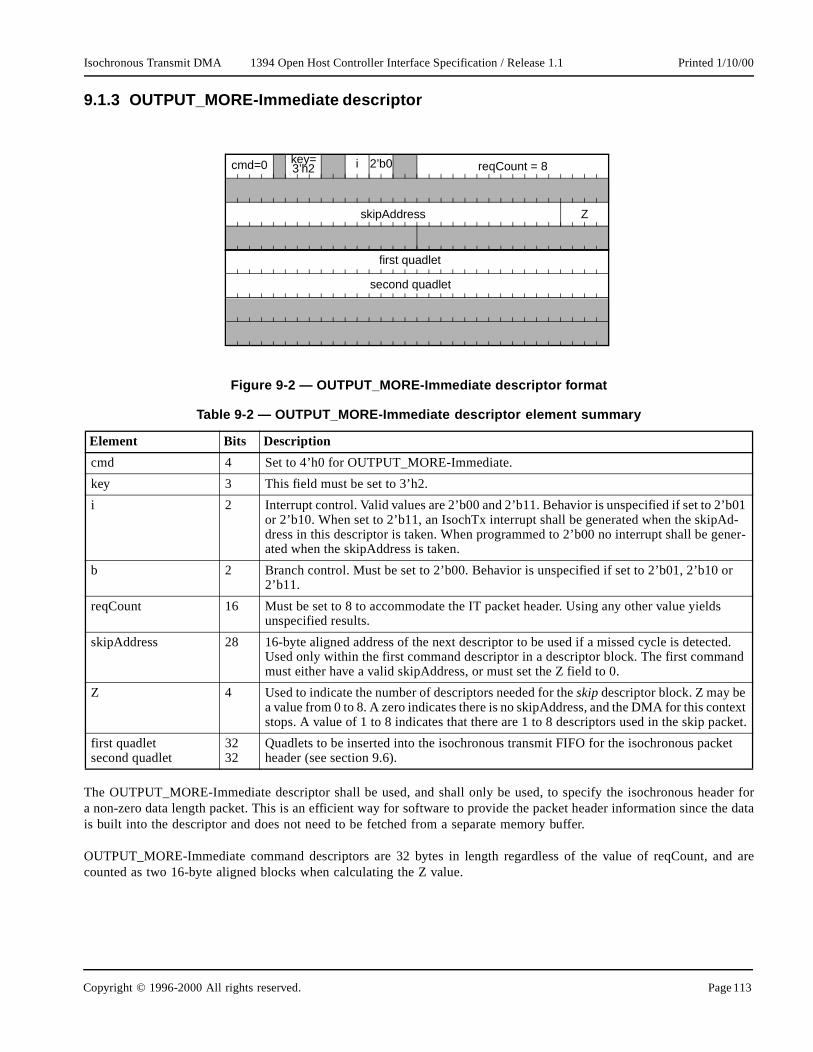
Isochronous Transmit DMA 1394 Open Host Controller Interface Specification / Release 1.1 Printed 1/10/00
ader for the data
and are
01 d-ner-
r
s
ted. nd
text cket.
et
9.1.3 OUTPUT_MORE-Immediate descriptor
The OUTPUT_MORE-Immediate descriptor shall be used, and shall only be used, to specify the isochronous hea non-zero data length packet. This is an efficient way for software to provide the packet header information sinceis built into the descriptor and does not need to be fetched from a separate memory buffer.
OUTPUT_MORE-Immediate command descriptors are 32 bytes in length regardless of the value of reqCount, counted as two 16-byte aligned blocks when calculating the Z value.
Figure 9-2 — OUTPUT_MORE-Immediate descriptor format
Table 9-2 — OUTPUT_MORE-Immediate descriptor element summary
Element Bits Description
cmd 4 Set to 4’h0 for OUTPUT_MORE-Immediate.
key 3 This field must be set to 3’h2.
i 2 Interrupt control. Valid values are 2’b00 and 2’b11. Behavior is unspecified if set to 2’bor 2’b10. When set to 2’b11, an IsochTx interrupt shall be generated when the skipAdress in this descriptor is taken. When programmed to 2’b00 no interrupt shall be geated when the skipAddress is taken.
b 2 Branch control. Must be set to 2’b00. Behavior is unspecified if set to 2’b01, 2’b10 o2’b11.
reqCount 16 Must be set to 8 to accommodate the IT packet header. Using any other value yieldunspecified results.
skipAddress 28 16-byte aligned address of the next descriptor to be used if a missed cycle is detecUsed only within the first command descriptor in a descriptor block. The first commamust either have a valid skipAddress, or must set the Z field to 0.
Z 4 Used to indicate the number of descriptors needed for the skip descriptor block. Z may be a value from 0 to 8. A zero indicates there is no skipAddress, and the DMA for this constops. A value of 1 to 8 indicates that there are 1 to 8 descriptors used in the skip pa
first quadletsecond quadlet
3232
Quadlets to be inserted into the isochronous transmit FIFO for the isochronous packheader (see section 9.6).
reqCount = 8
ZskipAddress
key=3’h2cmd=0 2’b0
first quadlet
second quadlet
i
Copyright © 1996-2000 All rights reserved. Page 113

Isochronous Transmit DMA 1394 Open Host Controller Interface Specification / Release 1.1 Printed 1/10/00
ast data
LAST
T is
tor
01 iptor et to
the
ted.
ptor
d is A ous
9.1.4 OUTPUT_LAST descriptor
The OUTPUT_LAST descriptor is used to indicate the end of a packet. If reqCount is non-zero, this specifies the lfragment for the packet. It shall not be used for specifying the packet header.
An OUTPUT_LAST with reqCount=0 is used to indicate that no packet is to be sent for the current cycle. The IT DMAcontroller will advance the context to the next descriptor block (branchAddress) for the next cycle. An OUTPUT_with a reqCount=0 shall not be preceded by any OUTPUT_MORE* descriptors in the descriptor block.
Figure 9-3 — OUTPUT_LAST command descriptor format
Table 9-3 — OUTPUT_LAST descriptor element summary
Element Bits Description
cmd 4 Set to 4’h1 for OUTPUT_LAST.Each command identifies one data fragment used to build the packet. OUTPUT_LASused to signify the end of the isochronous packet to be transmitted.
s 1 Status control. If set to one, xferStatus and timeStamp will be updated upon descripcompletion. If set to zero, neither field is updated.
key 3 This field must be set to 3’h0.
i 2 Interrupt control. Valid values are 2’b00 and 2’b11. Behavior is unspecified if set to 2’bor 2’b10. When set to 2’b11, an IsochTx interrupt shall be generated when the descris completed (see section 6.1) or the skipAddress in this descriptor is taken. When s2’b00, no interrupt shall be generated upon completion of this descriptor or when theskipAddress in this descriptor is taken.
b 2 Branch control. This field must be set to 2’b11 to branch to the location specified in branchAddress field. Behavior is unspecified for all other values.
reqCount 16 Request count: The size of the buffer in bytes pointed to by dataAddress.
dataAddress 32 Address of transmit buffer. dataAddress has no alignment restrictions.
branchAddress 28 16-byte aligned address of the next descriptor. Used only within OUTPUT_LAST* commands.
skipAddress 16-byte aligned address of the next descriptor to be used if a missed cycle is detecUsed only within the first command descriptor in a descriptor block. OUTPUT_LASTmay only be the first descriptor in a descriptor block when reqCount is 0.
Z 4 Used in OUTPUT_LAST to indicate the number of descriptors needed in the next descriptor block. Z may be a value from 0 to 8. A zero indicates this is the last descriin the list for this IT DMA context. A value of 1 to 8 indicates that there are 1 to 8 descriptors used in the next descriptor block.
xferStatus 16 Written with ContextControl [15:0] after the descriptor is processed if s = 1.
timeStamp 16 Contains the three low order bits of cycleSeconds and all 13 bits of cycleCount, anwritten when xferStatus is written. TimeStamp indicates the cycle for which the IT DMcontroller queued the transmission of this packet (if any). See section 5.13, “IsochronCycle Timer Register,” for information about cycle* fields.
s i b=2’b11 reqCount
dataAddress
Z
xferStatus
skip or descriptor branch Address
cmd=1
timeStamp
key=3’h0
Page 114 Copyright © 1996-2000 All rights reserved.

Isochronous Transmit DMA 1394 Open Host Controller Interface Specification / Release 1.1 Printed 1/10/00
der for as of the
lue
ted.
ochro-
9.1.5 OUTPUT_LAST-Immediate descriptor
The OUTPUT_LAST-Immediate descriptor must be used, and must only be used, to specify the isochronous heapacket with zero data bytes. OUTPUT_LAST-Immediate command descriptors are 32-bytes in length regardlesvalue of reqCount and are counted as two 16-byte aligned blocks when calculating the Z value.
Figure 9-4 — OUTPUT_LAST-Immediate command descriptor format
Table 9-4 — OUTPUT_LAST-Immediate descriptor element summary
Element Bits Description
cmd, s Same as in Table 9-3.
key 3 This field must be set to 3’h2.
i, b Same as in Table 9-3.
reqCount 16 Must be set to 16’h0008 to accommodate the IT packet header. Using any other vayields unspecified results.
branchAddress 28 16-byte aligned address of the next descriptor. Used only within OUTPUT_LAST* commands.
skipAddress 16-byte aligned address of the next descriptor to be used if a missed cycle is detecUsed only within the first command descriptor in a descriptor block.
Z, xferStatus, timeStamp
Same as in Table 9-3.
quadlets 32*4 The first and second quadlets are used to specify the 2 quadlets required for the isnous packet header. (See section 9.6).
s i reqCount = 8
Z
xferStatus
skip and descriptor branch Address
cmd=1
timeStamp
key=3’h2
first quadlet
second quadlet
b=2’b11
Copyright © 1996-2000 All rights reserved. Page 115

Isochronous Transmit DMA 1394 Open Host Controller Interface Specification / Release 1.1 Printed 1/10/00
ecifiednly onehall be
f usingy host
01 d-ner-
com- con-
is
d. The tore
text cket.
9.1.6 STORE_VALUE descriptor
The STORE_VALUE command descriptor instructs the Host Controller to write a specified 32-bit value to a sphost memory location. If used, STORE_VALUE must be the first command descriptor in a descriptor block, and ois permitted per descriptor block. STORE_VALUE must not be the only descriptor in a descriptor block and sfollowed by one or more OUTPUT_* descriptors. It has the following format.
The STORE_VALUE command provides a mechanism for software to monitor a context’s progress independent ointerrupts. For example a running IT context program could perform a STORE_VALUE periodically into a memorlocation where software would look to determine the latest IT DMA context progress.
Figure 9-5 — STORE_VALUE descriptor
Table 9-5 — STORE_VALUE descriptor element summary
Element Bits Description
cmd 4 Set to 4’h8 for STORE_VALUE.
key 3 This field must be set to 3’h6.
i 2 Interrupt control. Valid values are 2’b00 and 2’b11. Behavior is unspecified if set to 2’bor 2’b10. When set to 2’b11, an IsochTx interrupt shall be generated when the skipAdress in this descriptor is taken. When programmed to 2’b00 no interrupt shall be geated when the skipAddress is taken.
storeDoublet 16 16-bit value to be stored into the quadlet aligned dataAddress upon execution of thismand. StoreDoublet is written as a 32 bit value, where bits 31:16 are 0’s and bits 15:0tain the storeDoublet value provided in the descriptor.
dataAddress 32 Quadlet aligned host memory address into which storeDoublet (padded to 32) bitswritten.
skipAddress 28 16-byte aligned address of the next descriptor to be used if a missed cycle is detecteskipAddress must be valid or the Z field must be 0. If the skip address is used, the saction specified by this descriptor will not be executed.
Z 4 Used to indicate the number of descriptors needed for the skip descriptor block. Z may be a value from 0 to 8. A zero indicates there is no skipAddress, and the DMA for this constops. A value of 1 to 8 indicates that there are 1 to 8 descriptors used in the skip pa
dataAddress
cmd=8 storeDoublet
key=3’h6
ZskipAddress
i
Page 116 Copyright © 1996-2000 All rights reserved.

Isochronous Transmit DMA 1394 Open Host Controller Interface Specification / Release 1.1 Printed 1/10/00
iency. Z
g to the
r the
to five
not be
nd must on the
um of allare will
T orate thealready
riptor to
cies, ash Hostontextplica-
r blockrogram.
follows block).).
9.1.7 IT DMA descriptor usage
The Z value is used by the Host Controller to enable several descriptors to be fetched at once, for improved efficvalues must always be encoded correctly. The contiguous descriptors described by a Z value are called a descriptor block.The following table summarizes all legal Z values:
Each isochronous transmit descriptor block for a packet shall be specified with the command descriptors accordinfollowing rules:
• A maximum of 8 command descriptors may be used.• Only one STORE_VALUE may be used, and it must be the first descriptor in a descriptor block.• If STORE_VALUE is used, it shall be followed by at least one OUTPUT_* descriptor, and the Z value fo
descriptor block shall be between 2-8 inclusively.• If the packet dataLength is not zero, one OUTPUT_MORE-Immediate must be used, followed by zero
OUTPUT_MORE’s, followed by one OUTPUT_LAST.• If the packet dataLength is zero, one OUTPUT_LAST-Immediate must be used.• If no packet is to be sent during a cycle, one OUTPUT_LAST with reqCount=0 must be used and shall
preceded by any other OUTPUT_* descriptor.
The isochronous packet header must be specified using a *-Immediate command. The OUTPUT_LAST* commahave a branch control value of 2’b11. All other commands must have a branch control value of 2’b00. Dependingaggregate number of bytes being transmitted for one descriptor block, hardware may assist with padding. If the sreqCounts modulo 4 is 0, then padding is not necessary. If the sum of all reqCounts module 4 is not 0, then hardwinsert padding up to a quadlet boundary.
To indicate the end of the context program, all IT DMA context programs must use an OUTPUT_LASOUTPUT_LAST-Immediate command with a branch (b) value of 2’b11 (branch always) and a Z value of 0 to indicend of the program. A program which ends can be appended to while the DMA runs, even if the DMA has reached the last descriptor.
The first command in an isochronous packet descriptor block must have a skipAddress which points to the descbranch to if this packet cannot be transmitted (typically due to a lost cycle). The value of the Command.b field in thatdescriptor does not affect a skip branch.
The use of many OUTPUT_MORE* commands to describe a single packet will generally cause extra fetch latenthe Host Controller fetches payload buffers from different parts of memory. These latencies may differ for eacController implementation, bus, and host memory architecture. Software is expected to construct IT DMA cprograms with a sufficiently low number of OUTPUT_MORE* commands so that the Host Controller can satisfy aption-specific latency requirements.
IT DMA context programs must contain exactly one descriptor block to be processed per cycle. Each descriptomust be identified with an accurate Z value, both when the program is started, and on each branch within the pEach descriptor block must end with an unconditional branch to the next descriptor block, even if the next block immediately in consecutive memory. (The branch enables the IT DMA to learn the Z value for the next descriptorEach descriptor block must begin with a command that contains a branch to the skipAddress (also with a Z code
Table 9-6 — Z value encoding
Z value Use
0 Indicates that the current descriptor is the last descriptor in the context program.
1-8 Indicates that starting at descriptorAddress, there are one to eight 16-byte aligned physically contiguous descriptors and descriptor components.
9-15 reserved
Copyright © 1996-2000 All rights reserved. Page 117

Isochronous Transmit DMA 1394 Open Host Controller Interface Specification / Release 1.1 Printed 1/10/00
IT DMAis indi-s not a
used byare to
ntext isero. Theysically
ck
Some applications of isochronous transfer do not transfer a packet on every isochronous cycle. Therefore the will sometimes not transmit a packet for one or more channels. Within a context program, a non-transmit cycle cated by a descriptor block whose only transfer command is an OUTPUT_LAST with a reqCount of zero. (This izero-length packet, which would be sent with an OUTPUT_LAST-Immediate.)
9.2 IT Context Registers
Each isochronous transmit context consists of two registers: CommandPtr and IT ContextControl. CommandPtr issoftware to tell the IT DMA controller where the DMA context program begins. IT ContextControl is used by softwcontrol the context’s behavior, and is used by hardware to indicate current status.
9.2.1 CommandPtr
The CommandPtr register specifies the address of the context program which will be executed when a DMA costarted. All descriptors are 16-byte aligned, so the four least-significant bits of any descriptor address must be zfour least-significant bits of the CommandPtr register are used to encode a Z value that indicates how many phcontiguous descriptors are pointed to by descriptorAddress.
When ContextControl.run and ContextControl.active are set for an IT context, this field shall point to the descriptor blothat is currently being processed by the DMA.
Refer to section 3.1.2 for a full description of the CommandPtr register and special functionality for IT contexts.
Open HCI Offset 11’h20C + (16 * n) ; where n = 0 for contexts 0, n = 1 for context 1, etc.
Figure 9-6 — CommandPtr register format
31 30 29 28 27 25 2426 23 22 21 20 19 18 17 16 15 14 13 12 11 9 810 7 6 5 4 3 2 1 0
descriptorAddress [31:4] Z
Page 118 Copyright © 1996-2000 All rights reserved.

Isochronous Transmit DMA 1394 Open Host Controller Interface Specification / Release 1.1 Printed 1/10/00
for the in the
n thetion. A
andardle time.
ontext’s in low t gins.tor
is
ister are
on of
9.2.2 IT ContextControl Register
The IT ContextControl set and clear registers contain bits that control options, operational state, and status isochronous transmit DMA contexts. Software can set selected bits by writing ones to the corresponding bitsContextControlSet register. Software can clear selected bits by writing ones to the corresponding bits iContextControlClear register. It is not possible for software to set some bits and clear others in an atomic operaread from either register will return the same value.
The context control register used for isochronous transmit DMA contexts is shown below. In addition to the stContextControl fields as described in section 3.1.1, it includes a mechanism for starting transmit at a specified cyc
Open HCI Offset 11’h200 + (16 * n) - Set; where n = 0 for contexts 0, n = 1 for context 1, etc.
Open HCI Offset 11’h204 + (16 * n) - Clear
Figure 9-7 — IT DMA ContextControl (set and clear) register format
Table 9-7 — IT DMA ContextControl (set and clear) register description
field rscu reset description
cycleMatchEnable rscu undef When set to one, processing will occur such that the packet described by the cfirst descriptor block will be transmitted in the cycle whose number is specifiedthe cycleMatch field of this register. The 15-bit cycleMatch field must match the order two bits of cycleSeconds and the 13-bit cycleCount field in the cycle starpacket that is sent or received immediately before isochronous transmission beSince the IT DMA controller may work ahead, the processing of the first descripblock may begin slightly in advance of the actual cycle in which the first packettransmitted.The effects of this bit however are impacted by the values of other bits in this regand are explained below this table. Once the context has become active, hardwclears the cycleMatchEnable bit.
cycleMatch rsc undef Contains a 15-bit value, corresponding to the low order two bits of the bus CycleTime.cycleSeconds and the 13-bit CycleTime.cycleCount field. If ContextControl.cycleMatchEnable is set, then this IT DMA context will become enabled for transmits when the low order two bits of the bus CycleTime.cycleSeconds concatenated with CycleTime.cycleCount equals the cycleMatch value.
run rscu 1’b0 Refer to section 3.1.1.1 and the description following this table for an explanatithe ContextControl.run bit.
wake rsu undef Refer to section 3.1.1.2 for an explanation of the ContextControl.wake bit.
dead ru 1’b0 Refer to section 3.1.1.4 for an explanation of the ContextControl.dead bit.
active ru 1’b0 Refer to section 3.1.1.3 for an explanation of the ContextControl.active bit.
31 30 29 28 27 25 2426 23 22 21 20 19 18 17 16 15 14 13 12 11 9 810 7 6 5 4 3 2 1 0
deadactive
wake
run
cycleMatch
cycleMatchEnable
eventcode
{
reserved-undefined
Copyright © 1996-2000 All rights reserved. Page 119

Isochronous Transmit DMA 1394 Open Host Controller Interface Specification / Release 1.1 Printed 1/10/00
ing by
ts theMA
le bits.
bits of
becomes
sult in
ay not be
Refer
contextreceivesh DMA
ing the
eld.
es.
The cycleMatch field is used to start an IT DMA context program on a specified cycle. Software enables matchsetting the cycleMatchEnable bit. When the low order two bits of the bus CycleTime.cycleSeconds concatenated withCycleTime.cycleCount matches the cycleMatch value, hardware clears the cycleMatchEnable bit to 0, seContextControl.active bit to 1, and begins executing descriptor blocks for the context. The transition of an IT Dcontext to the active state from the not-active state is dependent upon the values of the run and cycleMatchEnab
• If run transitions to 1 when cycleMatchEnable is 0, then the context will become active (active = 1).• If both run and cycleMatchEnable are set to 1, then the context will become active when the low order two
the bus CycleTime.cycleSeconds and 13-bit CycleTime.cycleCount values match the 15-bit cycleMatch value.• If both run and cycleMatchEnable are set to 1, and cycleMatchEnable is subsequently cleared, the context
active.• If both run and active are 1 (the context is active), and then cycleMatchEnable is set to 1, this will re
unspecified behavior.
Due to software latencies, software attempts to manage the startup of a context too close to the current time meffective.
In addition, the usability of cycleMatchEnable for IT contexts will be impacted by the cycleInconsistent interrupt.to Section 9.5.1 for more information.
9.3 Isochronous transmit DMA controller
The following sections describe how software manages the multiple isochronous transmit DMA contexts. Each has a CommandPtr pointing to the current DMA descriptor. For every cycle start packet that the Host Controller or sends, the IT DMA controller can transmit exactly one descriptor block describing exactly one packet from eaccontext that is in the ContextControl.run state.
reserved undefined ru undef This field is specified as undefined and may contain any value without impactintended processing of this packet.
event code ru undef Following an OUTPUT_LAST* command, the error code is indicated in this fiPossible values are: ack_complete, evt_underrun, evt_descriptor_read, evt_data_read, evt_tcode_err, evt_timeout, and evt_unknown.See Table 3-2, “Packet event codes,” for descriptions and values for these cod
Table 9-7 — IT DMA ContextControl (set and clear) register description
field rscu reset description
Page 120 Copyright © 1996-2000 All rights reserved.

Isochronous Transmit DMA 1394 Open Host Controller Interface Specification / Release 1.1 Printed 1/10/00
enerally, indexinggramchannel
nding onAST forChannel 9packetsrmal next is lost,
ing any
contextr each
ent even
9.3.1 IT DMA Processing
Each IT DMA context command pointer corresponds to a list of packets to be sent on successive 1394 cycles. Geach list represents a single isochronous channel. Isochronous channel numbers are not tied to any internalscheme utilized by the Host Controller to track all implemented IT DMA contexts. Each IT DMA context propointed to by each CommandPtr will specify the entire isochronous packet header, including the isochronous number, for each packet that is transmitted. The entire IT DMA is summarized in the following figure:
In the example, three channels are being transmitted. Three cycles of transmit are shown. Context 0 is seisochronous channel 9, using an OUTPUT_MORE-Immediate to send each packet header and an OUTPUT_Leach payload. In cycle 2002 the payload spans a page boundary, so channel 9 uses an extra OUTPUT_MORE. will skip to the next packet if any cycle is lost. Context 1 is sending on isochronous channel 6, with zero length and only headers. Because channel 6 uses a single descriptor per packet, the skip branch is equal to the nopacket branch. Context 2 is sending on isochronous channel 42, with each skip branch pointing to itself. If a cyclechannels 6 and 9 will advance to the next packet, while channel 42 will fall behind by one packet, without skipppackets.
For every cycle, the IT DMA controller shall process each running context in order, from the lowest numbered through the highest numbered context. For each cycle, the IT DMA controller will complete one descriptor block foactive IT DMA context. Once a packet has been transferred into the transmit FIFO, the packet is considered sthough it may not have been transmitted yet on the 1394 wire.
Figure 9-8 — IT DMA summary
OUTPUT_MORE-I OUTPUT_MORE-I
OUTPUT_LAST
OUTPUT_MORE-I
OUTPUT_LAST
OUTPUT_LAST-I OUTPUT_LAST-I
OUTPUT_MORE-I
OUTPUT_LAST
OUTPUT_MORE-ICommandPtr 0 Z OUTPUT_MORE-I
OUTPUT_LAST OUTPUT_MORE
OUTPUT_LAST
chan
nel
9ch
anne
l 42
chan
nel
6
cycle 2001 cycle 2002 cycle 2003
skip
normal branch
CommandPtr 2 Z
CommandPtr 1 Z
OUTPUT_LAST-I
OUTPUT_LAST
Copyright © 1996-2000 All rights reserved. Page 121

Isochronous Transmit DMA 1394 Open Host Controller Interface Specification / Release 1.1 Printed 1/10/00
ntinue
ossiblecoupling
is keepss.ng things two, the
e time.r into the, the link
ecausecessary,
sending
a tingto the
IFO andich the
e firstskipped
to skipchannel genera-due to-specific
ission, transmit
ill thenontroller
s beenhe one
In the case of an underrun while the IT DMA controller is processing a context, the IT DMA controller shall cothrough its list of active contexts taking the skip branch address for each of the remaining contexts.
9.3.2 Prefetching IT Packets
The Host Controller is permitted to work up to two cycles ahead of the current cycle time. The result is that it’s pfor data for a 1394 cycle to be put into the FIFO long before it is sent on the bus. This in effect creates a time deof the host side (input) of the FIFO from the link side (output) of the FIFO.
Since the host side and the link side are not time synchronized, the host side may have its own cycle timer. Thtrack of the cycle number for which data is being put into the FIFO. It is not the same cycle timer that the link side useWhen the Host Controller is initialized, the timers are set to the same value and then the host side can start puttiinto the FIFO. Whenever the difference between the host side cycle time and the link side cycle time is less thanhost can start putting packets into the FIFO.
By working up to two cycles ahead it’s possible for two 1394 cycles worth of packets to be in the FIFO at the samTo convey to the link side where the 1394 cycle boundary is between the packets, the host side puts a delimiteFIFO each time processing is completed for all contexts for a cycle. When a cycle start appears on the 1394 busstarts taking packets out of the FIFO and sends the data on the bus until the link reaches the delimiter.
9.3.3 Isochronous Transmit Cycle Loss
The IT DMA controller can send multiple packets (multiple isochronous channels) in each isochronous cycle. Bisochronous cycles can be lost, the IT DMA is organized so that one cycle’s worth of packets can be skipped, if neto catch up. The loss of an isochronous cycle is usually uncommon, and typically results from a bus reset.
If isochronous cycles were lost, and no corrective action was taken, the transmitter would gradually fall behind, each packet some number of cycles after the transmission time intended by software.
In order to permit the transmitter to avoid falling behind, each packet in an IT DMA context program contains skipbranch address. Any time the IT DMA wants to correct for a cycle loss, it will follow this branch instead of transmitthe packet. For each cycle’s worth of packets (descriptor blocks), the IT DMA will either put all of the packets inFIFO and advance to the next descriptor block pointed to by branchAddress or will not put any packets into the Fwill advance to the next descriptor block pointed to by skipAddress. SkipAddress is used for any condition in whIT DMA cannot acquire the bus to transmit all packets for a cycle within that cycle.
If an IT DMA context performs skip processing, the context shall generate an IsochTx interrupt if the ‘i’ field of thdescriptor in the skipped descriptor block is set as 2’b11. This allows software to keep track of completed and descriptor blocks.
Software can use the skip branch in at least four ways. 1) Branching to the next packet will cause the IT DMApackets to recover from cycle loss. 2) Branching to the same packet will cause the IT DMA to fall behind (on that only) without skipping any packets due to cycle loss. 3) Branching to an alternate context program can allow thetion of an interrupt, and the possible early completion of transmission. 4) Stopping the IT DMA context program cycle loss. Software can use the third and fourth methods to cease transmission on cycle loss in the applicationcase that the receiver cannot tolerate either late or lost packets.
Because the Host Controller will generally load isochronous transmit packets into a FIFO in advance of transmsome packets may be considered complete when cycle loss is detected, even though they have not yet left theFIFO. In this situation, the Host Controller will hold those packets in the FIFO until they can be transmitted, and wcomplete the transmission of each context packet that had been intended to go out in the same cycle. The Host Cwill then apply the skip branching on the packets for the next cycle (the first cycle for which no transmission haperformed). If a context in the IT DMA is arranged to skip packets on cycle loss, the packet skipped will be t
Page 122 Copyright © 1996-2000 All rights reserved.

Isochronous Transmit DMA 1394 Open Host Controller Interface Specification / Release 1.1 Printed 1/10/00
orth of without
ep twoill fit)ped. Note
ould be 2,
ontext C
f-programtection of
ord theing skipts witht
scheduled for the cycle following the cycle that was lost. If the Host Controller preloads more than one cycle’s wpackets, the skip may be delayed by a similar number of cycles, so that the transmit FIFO can empty normally,being flushed.
The illustration in Figure 9-9 shows how each of these cases works. In this example, the IT DMA attempts to kecycles ahead of the bus. In other words, it tries to have two complete cycles in the transmit FIFO (if they wwhenever possible. Context A illustrates case 1 (above), where the skip branch is chosen so that packets are skipthat because of the FIFO preload, the two packets skipped on Context A (A4 and A5) follow a delayed packet (A3) thatwas already in the FIFO. While it might have been possible to skip only one packet if the FIFO was flushed, it wmuch harder for the Host Controller to have packet A5 ready in time to send it on cycle 6. Context B illustrates casewhere packets are not skipped. While context A loses two packets, context B instead falls two cycles behind. Cillustrates case 3, where transmission ends in response to a detected cycle loss. Packets C2 and C3 were already in theFIFO, so they are transmitted, followed by the end-of-program packet Cx. The descriptor block for packet Cx loops toitself in case additional cycles are lost before Cx is sent. This loop guarantees that Cx will be sent before the programends. Context D illustrates case 4, where transmission ends in response to a detected cycle loss without an end-opacket. The skip address indicates the end of list (Z=0) and no more packets are loaded into the FIFO upon decycle loss.
9.3.4 Skip Processing Overflow
A skip processing overflow occurs when recurring cycle skip conditions occur and the Host Controller cannot recnumber of cycle skips necessary to catch up. Open HCI implementations shall provide for at least three outstandevents before a skip processing overflow may occur. When a skip processing overflow occurs all IT DMA contexContextControl.run set shall set ContextControl.dead and IntEvent.unrecoverableError (see section 9.5.3), and shall seContextControl.eventcode status to evt_timeout.
To recover from a skip processing overflow software shall clear ContextControl.run for all IT DMA contexts withContextControl.run set, and verify these contexts are inactive before restarting any IT DMA contexts.
Copyright © 1996-2000 All rights reserved. Page 123

Isochronous Transmit DMA 1394 Open Host Controller Interface Specification / Release 1.1 Printed 1/10/00
ller will
o the
scriptor
f the ‘i’
In these examples, the packets that are “in the FIFO” assume an infinitely large transmit FIFO. The Host Controtransmit packets as shown, even if they are too big to actually fit into the FIFO.
If a cycle loss is detected while the IT DMA is mid packet, that context’s descriptor block will not branch tskipAddress, but will advance to the next descriptor block.
9.3.5 FIFO Underrun
If there is a FIFO underrun while processing an isochronous context, then the following shall occur:
• The packet that underran is lost. • The context with the underrun
1) does not write status to the descriptor block for to the underran packet, and
2) advances processing to the skipAddress contained in the descriptor block for the underrun packet.• Any contexts remaining to be processed for the now lost cycle will be processed by advancing to the next de
block pointed to by skipAddress• Any of the contexts that take the skipAddress as a result of the underrun will generate an IsochTx interrupt i
field in the first descriptor of the skipped descriptor block is set to 2’b11• The contexts shall be processed normally in the isochronous cycle that follows the underrun.
Figure 9-9 — Isochronous transmit cycle loss example
3 4 5 6 7 8 9 10
A1
C1
A2 A3 A4 A5 A6
B1 B2 B3 B4 B5 B6
C2 C3 C4 C5 C6
Cx
context A
context B
context C
A1 B1 C1 A2 B2 C2 A3 B3 C3 A6 B4 Cx A7 B5
A1
B1
C1
D1
A2
B2
A2
B2
C2
D2
A3
B3
B2
C2
D2
A3
B3
B2
C2
D2
A3
B3
A3
B3
C3
D3
A6
B4
A6
B4
Cx
A7
B5
A7
B5
A8
B6
BUS RESET ID
Tran
smit
FIF
O
D1context D0 0 0 0 0 0
C2
D2
D1
C3
D3
C3
D3
C3
D3
D2
Cx
D3
0
D2 D3 D4 D5 D6
Page 124 Copyright © 1996-2000 All rights reserved.

Isochronous Transmit DMA 1394 Open Host Controller Interface Specification / Release 1.1 Printed 1/10/00
ing will
from ariting
indicate
ithout DMAand the result inh, for
bit in theitMask
to onehat atXmitInt-r, see
ing
ust first
yo cycles
All actions to recover from the FIFO underrun shall be executed immediately after the underrun, and skip processdisrupt a minimum number of contexts.
9.3.6 Determining the number of implemented IT DMA contexts
The number of supported isochronous transmit DMA contexts may vary for 1394 Open HCI implementations minimum of four to a maximum of 32. Software can determine the number of supported IT DMA contexts by w32’hFFFF_FFFF to isoXmitIntMask register (see section 6.3.1), and then reading it back. Bits returned as 1’s supported contexts, and bits returned as 0’s indicate unsupported/unimplemented contexts.
9.4 Appending to an IT DMA Context Program
As described in Section 3.2.1.2, “Appending to Running List,” software may freely append to a context program wknowledge of where the controller is in processing the list of descriptor blocks. Unlike other DMA contexts, the ITcontexts can have two pointers that may require updating in the known last descriptor block; the skipAddress branchAddress. When an IT context has reached the end of its context program and active is 0, setting wake willusing the descriptor (not descriptor block) which had Z=0 and will use the provided address, be it a skip or brancretrieving the next descriptor block.
9.5 IT Interrupts
Each of the possible 32 isochronous transmit contexts can generate an interrupt, so each IT context has a isoXmitIntEvent register. Software can enable interrupts on a per-context basis by setting the corresponding isoXmbit to one.
To efficiently handle interrupts which could conceivably be generated from 32 different contexts in close proximity another, there is a single bit for all IT DMA contexts in the Host Controller IntEvent register. This bit signifies tleast one but potentially several IT DMA contexts attempted to generate an interrupt. Software can read the isoEvent register to find out which context(s) are involved. For more information on the isoXmitIntEvent registesection 6.3.1.
9.5.1 cycleInconsistent Interrupt
When the IntEvent.cycleInconsistent condition occurs (table 6-1), the IT DMA controller shall continue processrunning contexts normally, with the exception that contexts with the ContextControl.cycleMatchEnable bit set will remaininactive and cycleMatch processing shall be, in effect, disabled. To re-enable cycleMatch processing, software mstop the IT contexts for which cycleMatch is enabled (by clearing ContextControl.run to 0 and waiting forContextControl.active to go to 0), then must clear the IntEvent.cycleInconsistent interrupt. The stopped IT contexts mathen be started, but software should not schedule any transmits to occur for these contexts for at least twimmediately following the clearing of the interrupt condition.
9.5.2 busReset Interrupt
Bus reset does not affect isochronous transmit.
Copyright © 1996-2000 All rights reserved. Page 125

Isochronous Transmit DMA 1394 Open Host Controller Interface Specification / Release 1.1 Printed 1/10/00
-
diate oruired to
00
ftmost s, if
of the
9.5.3 UnrecoverableError Interrupt
The IT DMA context shall set ContextControl.dead, set ContextControl.eventcode to evt_timeout, and generate and unrecoverableError interrupt event when a skip processing overflow occurs as described in section 9.3.4.
9.6 IT Data Format
An isochronous transmit packet consists of two header quadlets (as specified in either the OUTPUT_MORE-ImmeOUTPUT_LAST-Immediate descriptor) and an optional data payload. The data payload in host memory is not reqbe aligned on a quadlet boundary. Padding is added by the Host Controller if needed. The format is as follows.
Figure 9-10 — Isochronous transmit format
Table 9-8 — Isochronous transmit fields
field name bits description
spd 3 This field indicates the speed at which this packet is to be transmitted. 3’b000 = 1Mbits/sec, 3’b001 = 200 Mbits/sec, and 3’b010 = 400 Mbits/sec, other values are reserved.
tag 2 The data format of the isochronous data (see IEEE 1394 specification)
chanNum 6 The channel number this data is associated with.
tcode 4 The transaction code for this packet.
sy 4 Transaction layer specific synchronization bits.
dataLength 16 Indicates the number of bytes in this packet.
isochronous data The data to be sent with this packet. The first byte of data must appear in the lebyte of the first quadlet of this field. The last quadlet should be padded with zeroenecessary.
padding If the dataLength mod 4 is not zero, then zero-value bytes are added onto the endpacket to guarantee that a whole number of quadlets is sent.
isochronous data
reserved
31 30 29 28 27 25 2426 23 22 21 20 19 18 17 16 15 14 13 12 11 9 810 7 6 5 4 3 2 1 0
chanNum tcode=4’hA sytag
padding (if needed)
dataLength reserved
spd
Page 126 Copyright © 1996-2000 All rights reserved.

Isochronous Transmit DMA 1394 Open Host Controller Interface Specification / Release 1.1 Printed 1/10/00
not sentrt of the
Note that packets to go out over the 1394 wire are constructed from this Host Controller internal format, and are in the exact order as shown above. For example, spd, shown in the first quadlet, is not transmitted at all as paisochronous packet header.
Copyright © 1996-2000 All rights reserved. Page 127

Isochronous Transmit DMA 1394 Open Host Controller Interface Specification / Release 1.1 Printed 1/10/00
Page 128 Copyright © 1996-2000 All rights reserved.

Isochronous Receive DMA 1394 Open Host Controller Interface Specification / Release 1.1 Printed 1/10/00
imum DMA receiveket-per-enate aseparatend time-
emory
E and
),
ted
d
10. Isochronous Receive DMA
The Isochronous Receive DMA (IR DMA) controller has a required minimum of four and an implementation maxof 32 isochronous receive DMA contexts. Each context is controlled by a DMA context program. One single IRcontext can receive packets from multiple isochronous channels, and the remaining DMA contexts can eachpackets from a single isochronous channel. IR DMA contexts can receive exactly one packet per buffer (pacbuffer), concatenate packets into a stream that completely fills each of a series of buffers (buffer-fill), or concatfirst portion of payload of each packet into one series of buffers and a second portion of payload into another series of buffers (dual-buffer mode). Packets may be received with or without isochronous packet headers astamps.
10.1 IR DMA Context Programs
For isochronous receive DMA, a context program is a list of DMA descriptors used to identify buffers in host minto which the Host Controller places received isochronous packets.
10.1.1 Buffer-Fill and Packet-per-Buffer Descriptors
There are two kinds of descriptor commands available in the packet-per-buffer and buffer-fill modes: INPUT_MORINPUT_LAST. These descriptors are 16 bytes in length and shall be aligned on a 16 byte boundary.
Figure 10-1 — INPUT_MORE/INPUT_LAST descriptor format
Table 10-1 — INPUT_MORE/INPUT_LAST descriptor element summary
Element Bits Description
cmd 4 Set to 4’h2 for INPUT_MORE, or set to 4’h3 for INPUT_LAST.INPUT_MORE is required for receiving packets in buffer-fill mode (see section 10.2.1and may also be used in packet-per-buffer mode.INPUT_LAST is required for receiving packets in packet-per-buffer mode (see section 10.2.2), and shall be the final descriptor in a descriptor block. It is not permitin buffer-fill mode.
s 1 Used with packet-per-buffer mode only (see section 10.2.2). If set to one, xferStatus anresCount will be updated upon descriptor completion. If set to zero, neither field is updated. Assumed to be one for buffer-fill mode.
key 3 This field shall be set to 3’b0.
i 2 Interrupt control. Valid values are 2’b11 to generate an IsochRx interrupt when the descriptor is completed (see section 6.1), or 2’b00 for no interrupt. The descriptor is completed in buffer-fill when resCount is written zero by the Host Controller, and is completed for packet-per-buffer when the residual count is updated. Behavior is unspecified for 2’b01 and 2’b10. In packet-per-buffer mode (see section 10.2.2), softwareshall set i to 0 in INPUT_MORE descriptors and hardware may ignore this field.
Z
bcmd=2 or 3 s key=
3’b0 i reqCount
dataAddress
resCount xferStatus
branchAddress
w
Copyright © 1996-2000 All rights reserved. Page 129

Isochronous Receive DMA 1394 Open Host Controller Interface Specification / Release 1.1 Printed 1/10/00
criptor.
ch0.3),
tor
ait
t to
f the
RE
ess d of
y ck, en
1.
a in
10.1.2 Dual-Buffer Descriptor
There is only one type of descriptor used in dual-buffer mode, and this is referred to as the DUALBUFFER desThis descriptor is 32-bytes in length, and shall be aligned on a 16 byte boundary.
b 2 Branch control. Valid values are 2’b11 to branch to branchAddress, and 2’b00 not tobranch. Behavior is unspecified for 2’b01 and 2’b10. For buffer-fill mode (see section 10.2.1), this field shall always be set to 2’b11.For packet-per-buffer mode (see section 10.2.2), this field shall be 2’b00 for INPUT_MORE commands and 2’b11 for INPUT_LAST commands.
w 2 Wait control. Valid values are 2’b11 to wait for a packet with a sync field whimatches the sync specified in the context’s IRContextMatch register (see section 1or 2’b00 not to wait.For packet-per-buffer mode, 2’b11 can only be used in the first descriptor of a descripblock. For buffer-fill mode a w of 2’b11 affects all packets received into the buffer - the wcondition will apply the sync match requirement to each packet to be received into theindicated buffer and not just to the first packet. If needed, the w field should be se2’b11 for only the first descriptor in a buffer-fill context program.Note that all packets are filtered on the IRContextMatch tag values regardless ovalue of this (w) field. Behavior is unspecified for 2’b01 and 2’b10.
reqCount 16 Request count: The size of the input buffer in bytes.
dataAddress 32 Address of receive buffer. Any receive buffer which will contain one or more packetheaders shall have a quadlet aligned dataAddress. Buffers to receive data only (no headers) may have a byte aligned dataAddress.
branchAddress 28 16-byte aligned address of the next descriptor. This field is not used for INPUT_MOcommands in packet-per-buffer mode.
Z 4 For buffer-fill mode (see section 10.2.1), Z shall be either 1 to indicate the branchAddris a valid address for the next INPUT_MORE, or 0 to indicate this descriptor is the enthe context program.For packet-per-buffer mode (see section 10.2.2), if the command is INPUT_LAST, Z mabe a value from 1 to 8 to indicate the number of descriptors in the next descriptor bloor 0 to indicate the end of the context program. If the command is INPUT_MORE, thZ is not used.
xferStatus 16 Composed of 16-bits from ContextControl[15:0].For buffer-fill mode, xferStatus is written when resCount is updated.For packet-per-buffer mode, xferStatus is written after the descriptor is processed if s =
resCount 16 Residual count: The number of bytes remaining in the dataAddress buffer (out of a maximum of reqCount). Written if in packet-per-buffer mode and s = 1, or each time packet is received in buffer-fill mode. For further details on when resCount is updatedbuffer-fill mode, see section 10.2.1.
Table 10-1 — INPUT_MORE/INPUT_LAST descriptor element summary
Element Bits Description
Page 130 Copyright © 1996-2000 All rights reserved.

Isochronous Receive DMA 1394 Open Host Controller Interface Specification / Release 1.1 Printed 1/10/00
R
ch0.3),chther in
f the
ach ple
uffer
econd-
for m.
Since DUALBUFFER is the only descriptor type used in dual-buffer mode, the typical descriptor cmd field is reserved forfuture use. Refer to section 10.2.3 for details on dual-buffer mode processing.
Figure 10-2 — DUALBUFFER descriptor format
Table 10-2 — DUALBUFFER descriptor element summary
Element Bits Description
s 1 Status control. This bit shall be set to one.
key 3 This field shall be set to 3’b0.
i 2 Interrupt control. Valid values are 2’b11 to generate an IsochRx interrupt when the descriptor is completed (see section 6.1), or 2’b00 for no interrupt. The DUALBUFFEdescriptor is complete when either the firstBuffer or the secondBuffer is filled and firstResCount or secondResCount is written zero by the Host Controller. Behavior isunspecified when this field is set to either for 2’b01 or 2’b10.
b 2 Branch control. This field shall be set to 2’b11.
w 2 Wait control. Valid values are 2’b11 to wait for a packet with a sync field whimatches the sync specified in the context’s IRContextMatch register (see section 1or 2’b00 not to wait. When set to 2’b11, the wait condition will apply the sync matrequirement to each packet to be received into the indicated buffers and not just to first packet. If needed, the w field should be set to 2’b11 for only the first descriptoa dual-buffer mode context program.Note that all packets are filtered on the IRContextMatch tag values regardless ovalue of this (w) field. Behavior is unspecified for 2’b01 and 2’b10.
firstSize 16 First size. This field specifies the fixed length in bytes of the first data information in epacket payload to stream into the buffer pointed to by firstBuffer and shall be a multiof four bytes.
firstReqCount 16 First data request count. Specifies the size of the buffer in bytes pointed to by firstBand shall be a multiple of firstSize.
secondReqCount 16 Second data request count. Specifies the size of the buffer in bytes pointed to by sBuffer.
branchAddress 28 16-byte aligned address of the next descriptor when Z is non-zero.
Z 4 This field shall be either set to 4’h2 to indicate the branchAddress is a valid addressthe next descriptor, or 4’h0 to indicate this descriptor is the end of the context progra
secondBuffer
Z
bs key=3’b0 i firstSize
secondResCount firstResCount
branchAddress
w
firstBuffer
secondReqCount firstReqCount
Copyright © 1996-2000 All rights reserved. Page 131

Isochronous Receive DMA 1394 Open Host Controller Interface Specification / Release 1.1 Printed 1/10/00
cy. The
MA
ontext
t pro- trol-
pro-
s that cond st cord-
ffer
cond
10.1.3 Descriptor Z Values
The Z value is used by the Host Controller to fetch multiple command descriptors at once, for improved efficiencontiguous descriptors described by a Z value are called a descriptor block. The following table summarizes all legal Zvalues:
All IR DMA context programs shall indicate the end of the program by using a command descriptor with a b value of2’b11 (branch always) and a Z value of 0. A context program can be appended to while the DMA runs, even if the Dhas already reached the last descriptor. Section 3.2.1.2 describes how to append to a context program.
When an IR DMA context is running and/or active, software shall not modify any command descriptors within the cprogram with the exception of the last command descriptor (the one descriptor in a program with b=2’b11 and Z=4’h0).The last command descriptor may only be modified according to the steps described in section 3.2.1.2.
firstResCount 16 First buffer residual count. Software shall initialize this field to the same value as thagrammed in firstReqCount. Hardware shall update this field with the current first databuffer residual count in bytes after each packet is successfully received. The Host Conler shall update firstResCount and back packets out of the firstBuffer according to thecedure described in section 10.2.1 for the buffer-fill receive mode.
secondResCount 16 Second buffer residual count. Software shall initialize this field to the same value aprogrammed in secondReqCount. Hardware shall update this field with the current sedata buffer residual count in bytes after each packet is successfully received. The HoController shall update secondResCount and back packets out of the secondBuffer acing to the procedure described in section 10.2.1 for the buffer-fill receive mode.
firstBuffer 32 First buffer pointer. This field specifies the physical address of the start of the first buand shall be quadlet aligned.
secondBuffer 32 Second buffer pointer. This field specifies the physical address of the start of the sebuffer.
Table 10-3 — Z value encoding
Z value Use
0 Indicates that the current descriptor is the last descriptor in the context program.
1-8 Indicates that one to eight 16-byte aligned blocks starting at descriptorAddress are phys-ically contiguous.
9-15 reserved
Table 10-2 — DUALBUFFER descriptor element summary
Element Bits Description
Page 132 Copyright © 1996-2000 All rights reserved.

Isochronous Receive DMA 1394 Open Host Controller Interface Specification / Release 1.1 Printed 1/10/00
n place
tered outffers in
OREbsequentt the
iptor.
ers for a
n the
e to the Write
us and
uffer’s
saved
ntaininghen the
10.2 Receive Modes
The Host Controller can write isochronous receive packets into host memory buffers in one of three ways. It cathem using either buffer-fill mode, packet-per-buffer mode, or dual-buffer mode.
10.2.1 Buffer Fill Mode
In bufferFill mode, all received packets are concatenated into a contiguous stream of data. This data is then meinto buffers described by a DMA context program, filling each buffer completely. Packets may straddle multiple buthis mode (see packet 2 in the illustration below).
A context program for an isochronous receive context in buffer-fill mode consists of a list of independent INPUT_Mdescriptors, each branching to the next descriptor in the list. Since each descriptor shall always branch to the suone, the b field shall always be set to 2’b11 to indicate a branch. If a buffer-fill mode INPUT_MORE descriptor is nolast descriptor in the list, its Z value shall be set to 1 to instruct the Host Controller to fetch the next single descr Ifit is the last one in the list, Z shall be set to 0. Also, to ensure an accurate resCount value software shall initializeresCount to the value of reqCount.
As depicted above, it is possible for a received packet to straddle multiple buffers. To ensure that the receive buffcontext remain parsable, hardware shall follow the following procedure.
1) After filling to the end of a buffer with a partial packet, advance to the next descriptor block and obtainext buffer (dataAddress), retaining all state for the first buffer as well as for the new buffer.
2) Continue writing packet bytes into the subsequent buffer(s). If the end of a buffer is reached, advancnext buffer without updating xferStatus and retaining only cummulative interrupt state (section 6.4.1).the remaining packet bytes into the final packet buffer.
3) If there is no data error: a) conditionally write the trailer quadlet into the last buffer, b) update xferStatresCount into the final buffer’s descriptor, and c) update xferStatus and resCount into the first buffer’sdescriptor. At that point the previous state of the first buffer is no longer needed and the first bdescriptor is completed.
4) If there is an error, then the packet shall be ‘backed-out’ by reverting back to the previous state (asearlier). XferStatus and resCount are not updated for either descriptor.
By following these steps, the IR context buffers remain intact and can be parsed. Since interim buffers (those coan inner portion of one packet) will not have their status updated, software shall only use resCount values wcorresponding xferStatus indicates the active bit is set to one. It follows from this that if the xferStatus.active bit is set ina descriptor, then all prior descriptors have been filled.
Figure 10-3 — IR Buffer Fill Mode
et 2 packet 3
MORE s key=0 i b=3 reqCount
dataAddress
Z=1
resCount=0xferStatus
branchAddress
MORE s key=0 i b=3 reqCount
dataAddress
Z=1
resCountxferStatus
branchAddress
packet 1 pack
w
w
Copyright © 1996-2000 All rights reserved. Page 133

Isochronous Receive DMA 1394 Open Host Controller Interface Specification / Release 1.1 Printed 1/10/00
leftoverST are
ve beenmmand
r blocks. 0 to 7ller toransfer.e or shall
For information on the effect of a host bus error on an IR DMA context in buffer-fill mode, refer to section 13.2.6.
10.2.2 Packet-per-Buffer Mode
In packet-per-buffer mode, each received packet is placed in the buffer(s) described by one descriptor block. Anybytes are discarded, and packets never straddle multiple descriptor blocks. Both INPUT_MORE and INPUT_LAallowed in packet-per-buffer mode. Each INPUT_LAST marks the end of a packet, though the final byte may haused up in a previous INPUT_MORE (see packet 2 in the illustration below). Each packet starts in an INPUT_* cothat follows an INPUT_LAST.
A context program for an isochronous receive context in packet-per-buffer mode consists of a series of descriptoEach descriptor block describes buffers that will receive one packet and shall contain a contiguous set ofINPUT_MORE descriptors, followed by one INPUT_LAST descriptor. This requirement permits the Host Controprefetch all the descriptors for a packet, in order to avoid fetching additional descriptors during a packet tINPUT_MORE descriptors shall have the b field set to 2’b00 (never branch). INPUT_LAST descriptors shall have thbfield set to 2’b11 (always branch), and shall either have a valid address in branchAddress with a Z value of 1 to 8,have a Z value of 0 to indicate it’s the last descriptor in the context program.
Figure 10-4 — packet-per-buffer receive mode
w
w
MORE s key=0 i=0 b=0 reqCount
dataAddress
X
resCount [not written]xferStatus [not written]
X
w
LAST s key=0 i b=3 reqCount
dataAddress
Z=2
resCountxferStatus
branchAddress
pack
et 1
MORE s key=0 i=0 b=0 reqCount
dataAddress
X
resCountxferStatus
X
LAST s key=0 i b=3 reqCount
dataAddress
Z=2
resCount [not written]xferStatus [not written]
branchAddress
packet 2
MORE s key=0 i=0 b=0 reqCount
dataAddress
X
resCount [not written]xferStatus [not written]
X
LAST s key=0 i b=3 reqCount
dataAddress
Z=2
resCountxferStatus
branchAddress
p
acket 3
Page 134 Copyright © 1996-2000 All rights reserved.

Isochronous Receive DMA 1394 Open Host Controller Interface Specification / Release 1.1 Printed 1/10/00
13.2.6.
e bufferas the zero
er updated,s quadlet
middle buffer ignored.pt
mode is
s
t portiontilizing
isoch-from theceivednd portioneries. The
e part of
e field to
or has secon-up first
t portion
retireder packet 5ns (i.e.
For information on the effect of a host bus error on an IR DMA context in packet-per-buffer mode, refer to section
10.2.2.1 Command.xferStatus and Command.resCount updates
In packet-per-buffer mode, when s=1 the xferStatus and resCount fields are updated only in the descriptor for thwhich receives the last byte of the packet. ResCount is only valid in a descriptor if the xferStatus field hContextControl.active bit set. To obtain accurate values for xferStatus, software should initialize xferStatus to(evt_no_status).
In figure 10-4 above, there are 3 shaded xferStatus quadlets. The shaded quadlets are status fields that were nevand the unshaded status quadlets reflect status fields that were updated. In the top descriptor block, the xferStatuin the first descriptor was not written because packet 1 did not complete in the first descriptor’s buffer. In the descriptor block, the first descriptor was big enough to hold packet 2 completely. Since the first descriptor’sreceived the last byte of packet 2, the first descriptor’s status was written, and the second descriptor’s status isAlthough the OUTPUT_LAST’s status is ignored in this example, its i bit is used to determine whether or not an interruis triggered for this descriptor block.
If a descriptor block describes buffer space that cannot fit an entire packet (including header if isochHeader enabled), then the overflow bytes are discarded. When this occurs, xferStatus.ack will be set to evt_long_packet.
10.2.3 Dual-Buffer Mode
Dual-buffer mode is selected by setting the ContextControl.dualBufferMode bit to one before starting an isochronoureceive context. When ContextControl.dualBufferMode is set to one, the ContextControl.multiChanMode and Context-Control.bufferFill bits shall be programmed to zero.
When an isochronous receive context is in dual-buffer mode, all received packets are viewed as containing a firsof the payload followed by a second portion. This view of isochronous packet data aligns with several protocols uisochronous services.
The dual-buffer mode operations are similar to buffer-fill mode, but provide two separate series of buffers to streamronous packet data: firstBuffer series and secondBuffer series. The Host Controller separates the first portion second portion of packet payload per the firstSize field of the DUALBUFFER descriptor. The first portions of repackets are concatenated into a contiguous stream of data and metered out into the firstBuffer series. The secoof received packets are concatenated into a contiguous stream of data and metered out into the secondBuffer sfirstBuffer and secondBuffer series are described by the DUALBUFFER descriptors.
The data formats for dual-buffer mode are described in section 10.6.2. The isochronous header and trailer shall bthe firstBuffer series and shall not be presented to the secondBuffer series if ContextControl.isochHeader is set. To ensurethat the header and trailer information is not presented to the secondBuffer series, software shall set the firstSizat least eight bytes when ContextControl.isochHeader is set.
DUALBUFFER descriptors shall be retired when either the firstBuffer or secondBuffer indicated by the descriptbeen filled by the Host Controller and a residual count of zero has been written to either firstResCount ordResCount. FirstBuffer data shall not span a buffer pointed to by a DUALBUFFER descriptor. Software shall set data buffers in multiples of firstSize (including header and trailer quadlets if ContextControl.isochHeader is set).Hardware shall subtract firstSize from firstResCount for each packet received. This ensures that each packet’s firsbegins at a predetermined address in the firstBuffer.
The diagram that follows illustrates a sequence of packets of varying length. The first DUALBUFFER descriptor isafter packet 2 second data payload has spanned the second data buffer, and the second descriptor is retired aftfirst data completely fills the first data buffer. The Host Controller may receive packets with empty second portioonly first data payload), and this is illustrated in the following diagram with packets 3 and 4.
Copyright © 1996-2000 All rights reserved. Page 135

Isochronous Receive DMA 1394 Open Host Controller Interface Specification / Release 1.1 Printed 1/10/00
l-bufferffer-fill
owing
nto the
dBuffer +nal bytes
t with aCount -
ock, thenblock’s
adlet shall are not
6.
The Host Controller shall support second data payload for a received packet to straddle multiple buffers. In duamode, the Host Controller shall follow the procedure for residual count update and ‘backing-out’ described for bumode in section 10.2.1.
When the IR DMA context receives a packet while in dual-buffer mode, the Host Controller shall perform the follactions:
• store up to firstSize bytes from the beginning of the packet (including header & trailer quadlets if enabled) ifirstBuffer starting at address (firstBuffer + firstReqCount - firstResCount);
• store up to secondResCount bytes of packet data, if any, into the second buffer starting at address (seconsecondReqCount - secondResCount). Pad bytes are not stored in the second buffer. Note: if there are additioin the packet, processing proceeds to the next DMA descriptor block to store data in its second buffer;
• if the packet was received without error then store the new values for firstResCount and secondResCounsingle write. The new values are: firstResCount = firstResCount - firstSize; secondResCount = secondResbytes_stored_in_second_buffer. Note: if the packet data length causes an advance to a new descriptor blthat block’s secondResCount is updated without changing its firstResCount, next the original descriptor firstResCount and secondResCount are updated.
• completes this descriptor block when firstResCount or secondResCount is written as zero
If a packet is received that is not large enough to fill firstSize bytes of the firstBuffer (including header & trailer qusif enabled), the Host Controller shall treat the packet as if it exactly filled firstSize bytes of the firstBuffer, andupdate firstResCount accordingly. The buffer locations not filled by the short packet have undefined contents, andused to store a subsequent packet.
For information on the effect of a host bus error on an IR DMA context in dual-buffer mode, refer to section 13.2.
Figure 10-5 — IR Dual-Buffer Mode
pkt 4 first
pkt 2 first
pkt 1 second
pkt 2 sec (cont)
pkt 1 first
secondBuffer
Z = 2
bs i firstSize
secondResCount firstResCount
branchAddress
w
firstBuffer
secondReqCount firstReqCount
key
secondBuffer
Z = 2
bs i firstSize
secondResCount firstResCount
branchAddress
w
firstBuffer
secondReqCount firstReqCount
key
pkt 2 second
pkt 3 first
pkt 5 second
pkt 5 first
Page 136 Copyright © 1996-2000 All rights reserved.

Isochronous Receive DMA 1394 Open Host Controller Interface Specification / Release 1.1 Printed 1/10/00
tMatch.tCon-
Context-ibly sync
ontext isero. Theysicallyet-per-
receive
turn the
10.3 IR Context Registers
Each isochronous receive context consists of three registers: CommandPtr, IRContextControl, and IRContexCommandPtr is used by software to tell the IR DMA controller where the DMA context program begins. IRContextrol is used by software to control the context’s behavior, and is used by hardware to indicate current status. IRMatch is used to start on a specified cycle number and to filter received packets based on their tag bits and possbits. This section describes each register in detail.
10.3.1 CommandPtr
The CommandPtr register specifies the address of the context program which shall be executed when a DMA cstarted. All descriptors are 16-byte aligned, so the four least-significant bits of any descriptor address shall be zfour least-significant bits of the CommandPtr register are used to encode a Z value that indicates how many phcontiguous descriptors are pointed to by descriptorAddress. In buffer-fill mode, Z will be either one or zero. In packbuffer mode, Z will be from zero to eight.
Refer to section 3.1.2 for a full description of the CommandPtr register.
10.3.2 IR ContextControl register (set and clear)
The IR ContextControl register contains bits that control options, operational state, and status for the isochronous DMA contexts. Software can set selected bits by writing ones to the corresponding bits in the ContextControlSet register.Software can clear selected bits by writing ones to the corresponding bits in the ContextControlClear register. It is notpossible for software to set some bits and clear others in an atomic operation. A read from either register will resame value.
Open HCI Offset 11’h40C + (32 * n) ; where n = 0 for context 0, n = 1 for context 1, etc.
Figure 10-6 — CommandPtr register format
31 30 29 28 27 25 2426 23 22 21 20 19 18 17 16 15 14 13 12 11 9 810 7 6 5 4 3 2 1 0
descriptorAddress [31:4] Z
Copyright © 1996-2000 All rights reserved. Page 137
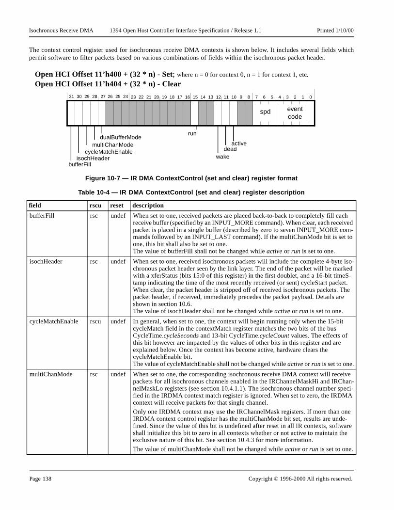
Isochronous Receive DMA 1394 Open Host Controller Interface Specification / Release 1.1 Printed 1/10/00
which
ach ived om- to
yte iso-rked S-et. The re
-bit
ceive han-
speci-A
ne e-are e
The context control register used for isochronous receive DMA contexts is shown below. It includes several fieldspermit software to filter packets based on various combinations of fields within the isochronous packet header.
Open HCI Offset 11’h400 + (32 * n) - Set; where n = 0 for context 0, n = 1 for context 1, etc.
Open HCI Offset 11’h404 + (32 * n) - Clear
Figure 10-7 — IR DMA ContextControl (set and clear) register format
Table 10-4 — IR DMA ContextControl (set and clear) register description
field rscu reset description
bufferFill rsc undef When set to one, received packets are placed back-to-back to completely fill ereceive buffer (specified by an INPUT_MORE command). When clear, each recepacket is placed in a single buffer (described by zero to seven INPUT_MORE cmands followed by an INPUT_LAST command). If the multiChanMode bit is setone, this bit shall also be set to one.The value of bufferFill shall not be changed while active or run is set to one.
isochHeader rsc undef When set to one, received isochronous packets will include the complete 4-bchronous packet header seen by the link layer. The end of the packet will be mawith a xferStatus (bits 15:0 of this register) in the first doublet, and a 16-bit timetamp indicating the time of the most recently received (or sent) cycleStart packWhen clear, the packet header is stripped off of received isochronous packets.packet header, if received, immediately precedes the packet payload. Details ashown in section 10.6.The value of isochHeader shall not be changed while active or run is set to one.
cycleMatchEnable rscu undef In general, when set to one, the context will begin running only when the 15cycleMatch field in the contextMatch register matches the two bits of the bus CycleTime.cycleSeconds and 13-bit CycleTime.cycleCount values. The effects of this bit however are impacted by the values of other bits in this register and areexplained below. Once the context has become active, hardware clears the cycleMatchEnable bit.The value of cycleMatchEnable shall not be changed while active or run is set to one.
multiChanMode rsc undef When set to one, the corresponding isochronous receive DMA context will repackets for all isochronous channels enabled in the IRChannelMaskHi and IRCnelMaskLo registers (see section 10.4.1.1). The isochronous channel number fied in the IRDMA context match register is ignored. When set to zero, the IRDMcontext will receive packets for that single channel.
Only one IRDMA context may use the IRChannelMask registers. If more than oIRDMA context control register has the multiChanMode bit set, results are undfined. Since the value of this bit is undefined after reset in all IR contexts, softwshall initialize this bit to zero in all contexts whether or not active to maintain thexclusive nature of this bit. See section 10.4.3 for more information.
The value of multiChanMode shall not be changed while active or run is set to one.
31 30 29 28 27 25 2426 23 22 21 20 19 18 17 16 15 14 13 12 11 9 810 7 6 5 4 3 2 1 0
deadactive
wakeisochHeader
multiChanMode
bufferFill
run
cycleMatchEnable
eventcode
spd
dualBufferMode
Page 138 Copyright © 1996-2000 All rights reserved.

Isochronous Receive DMA 1394 Open Host Controller Interface Specification / Release 1.1 Printed 1/10/00
acket’she IR
-active
et’s low the IR
becomes
sult in
ayload s
on of
are
mis-re
es.
The cycleMatchEnable bit is used to start an IR DMA context program on a specified cycle. When the cycleStart plow order two bits of cycleSeconds and 13-bit cycleCount values match the 15-bit cycleMatch value (in tcontextMatch register), hardware sets the cycleMatchEnable bit to 0, sets the ContextControl.active bit to 1, and beginsexecuting descriptor blocks for the context. The transition of an IR DMA context to the active state, from the notstate is dependent upon the values of the run and cycleMatchEnable bits.
• If run transitions to 1 when cycleMatchEnable is 0, then the context will become active (active = 1).• If both run and cycleMatchEnable are set to 1, then the context will become active when the cycleStart pack
order two bits of cycleSeconds and 13-bit cycleCount values match the 15-bit cycleMatch value indicated incontextMatch register.
• If both run and cycleMatchEnable are set to 1, and cycleMatchEnable is subsequently cleared, the context active.
• If both run and active are 1 (the context is active), and then cycleMatchEnable is set to 1, this will reunspecified behavior.
dualBufferMode rsc undef When set to one, received packets shall be separated into first and second pand streamed independently to the firstBuffer series and secondBuffer series adescribed in section 10.2.3. Both multiChanMode and bufferFill shall be pro-grammed to zero when this bit is set.
The value of dualBufferMode shall not be changed while active or run is set to one.
run rscu 1’b0 Refer to section 3.1.1.1 and the description following this table for an explanatithe ContextControl.run bit.
wake rsu undef Refer to section 3.1.1.2 for an explanation of the ContextControl.wake bit.
dead ru 1’b0 Refer to section 3.1.1.4 for an explanation of the ContextControl.dead bit.
active ru 1’b0 Refer to section 3.1.1.3 for an explanation of the ContextControl.active bit.
spd ru undef This field indicates the speed at which the packet was received. 3’b000 = 100Mbits/sec, 3’b001 = 200 Mbits/sec and 3’b010 = 400 Mbits/sec. All other valuesreserved.
event code ru undef For bufferFill mode, possible values are: ack_complete, evt_descriptor_read, evt_data_write and evt_unknown. Packets with data errors (either dataLength matches or dataCRC errors) and packets for which a FIFO overrun occurred a‘backed-out’ as described in section 10.2.1.For packet-per-buffer mode, possible values are: ack_complete, ack_data_error,evt_long_packet, evt_overrun, evt_descriptor_read, evt_data_write and evt_unknown.See Table 3-2, “Packet event codes,” for descriptions and values for these cod
Table 10-4 — IR DMA ContextControl (set and clear) register description
field rscu reset description
Copyright © 1996-2000 All rights reserved. Page 139

Isochronous Receive DMA 1394 Open Host Controller Interface Specification / Release 1.1 Printed 1/10/00
sochro-ed for a
forever.
’b11.
’b10.
’b01.
’b00.
s and
ly ield the
e
ne
A con-
10.3.3 Isochronous receive contextMatch register
The IR ContextMatch register is used to start a context running on a specified cycle number, to filter incoming inous packets based on tag values and to wait for packets with a specified sync value. All packets are checkmatching tag value, and a compare on sync is only performed when the descriptor’s w field is set to 2’b11. Seesection 10.1 for proper usage of the w field. This register should only be written when ContextControl.active is 0, other-wise unspecified behavior will result.
At least one tag bit shall be set to 1, otherwise no received packets will match and the context will, in effect, wait
Open HCI Offset 11’h410 + (32 * n) ; where n = 0 for context 0, n = 1 for context 1, etc.
Figure 10-8 — IR DMA ContextMatch register format
Table 10-5 — IR DMA ContextMatch register description
field rwu reset description
tag3 rw undef If set, this context will match on isochronous receive packets with a tag field of 2
tag2 rw undef If set, this context will match on isochronous receive packets with a tag field of 2
tag1 rw undef If set, this context will match on isochronous receive packets with a tag field of 2
tag0 rw undef If set, this context will match on isochronous receive packets with a tag field of 2
cycleMatch rw undef Contains a 15-bit value, corresponding to the low order two bits of cycleSecondthe 13-bit cycleCount field in the cycleStart packet. If ContextControl.cycleMatchEnable is set, then this IR DMA context will become enabled for receives when the two low order bits of the bus cycleTime.cycleSeconds and cycleTime.cycleCount values equal the cycleMatch value.
sync rw undef This field contains the 4 bit field which is compared to the sync field of each isochronous packet for this channel when the command descriptor’s w field is set to 2’b11.
tag1SyncFilter rw
**
undef If set to one and the contextMatch.tag1 bit is set, then packets with tag 2’b01 shall onbe accepted into the context if the two most-significant bits of the packet’s sync fare 2’b00. Packets with tag values other than 2’b01 shall be filtered according totag0, tag2 and tag3 bits above with no additional restrictions.
If clear, this context will match on isochronous receive packets as specified in thtag0-3 bits above with no additional restrictions.
** If LinkControl. tag1SyncFilterLock is set, then this bit is read only and is set to oby the OHCI.
channelNumber rw undef This six bit field indicates the isochronous channel number for which this IR DMtext will accept packets.
31 30 29 28 27 25 2426 23 22 21 20 19 18 17 16 15 14 13 12 11 9 810 7 6 5 4 3 2 1 0
channelNumbercycleMatch
tag3tag2
tag1
tag0
sync
tag1SyncFilter
Page 140 Copyright © 1996-2000 All rights reserved.

Isochronous Receive DMA 1394 Open Host Controller Interface Specification / Release 1.1 Printed 1/10/00
text hastart thegisters
xtCon-avail- the
tiChan-
hannel
channels.ltiChan-es to the
led. Theard reset
10.4 Isochronous receive DMA controller
The following sections describe how software manages the multiple isochronous receive DMA contexts. Each cona CommandPtr pointing to the initial DMA descriptor, a ContextControl register, and a contextMatch register to scontext based on a cycle number and to filter packets. The IR DMA controller has one set of IRMultiChanMask reused to specify a set of isochronous channels for the single isochronous context in multiChanMode.
10.4.1 Isochronous receive multi-channel support
Any IR DMA context can receive packets from multiple isochronous channels per cycle by enabling Contetrol.multiChanMode and using the IRMultiChanMask registers. There is a single set of IRMultiChanMask registers able in the IR DMA controller, and only one IR DMA context may be using them at any given time as determined bysetting of ContextControl.multiChanMode bit (see section section 10.3.2).
A context to be enabled for multiChanMode, shall also be enabled for bufferFill and isochHeader modes. If mulMode is enabled without bufferFill and isochHeader, the resulting behavior is undefined.
If an IR DMA context is in multi-channel mode, therefore using the IRMultiChanMask registers, the isochronous cfield in the IR DMA context Match register (section 10.3.3) is ignored.
10.4.1.1 IRMultiChanMask registers (set and clear)
An isochronous channel mask is used to enable packet receives from up to 64 specified isochronous data Software enables receives for any number of isoch channels by writing ones to the corresponding bits in the IRMuMaskHiSet and IRMultiChanMaskLoSet addresses. To disable receives for any isoch channels, software writes oncorresponding bits in the IRMultiChanMaskHiClear and IRMultiChanMaskLoClear addresses.
A read of each IRChanMask register shows which channels are enabled; a one for enabled, a zero for disabIRMultiChanMask registers are not changed by a bus reset. The state of these registers is undefined following a hor soft reset.
Open HCI Offset 11’h070 - SetOpen HCI Offset 11’h074 - Clear
Figure 10-9 — IRMultiChanMaskHi (set and clear) register
31 30 29 28 27 25 2426 23 22 21 20 19 18 17 16 15 14 13 12 11 9 810 7 6 5 4 3 2 1 0
isoChannel62isoChannel61
isoChannel60 isoChannel35isoChannel34
isoChannel63isoChannel33
isoChannel32
Copyright © 1996-2000 All rights reserved. Page 141

Isochronous Receive DMA 1394 Open Host Controller Interface Specification / Release 1.1 Printed 1/10/00
el. Data
xtMatch
ble thes
ns
the sync
uffert which
run bit ists will be
destina-
r
e packet
10.4.2 Isochronous receive single-channel support
Each isochronous receive DMA context can receive one packet per cycle from one isochronous data channchaining across DMA context commands is supported when either the ContextControl.bufferFill or the ContextCon-trol.dualBufferMode bits are set.
To configure a context to receive packets from an isochronous channel, write the channel number into the conteregister’s channelNumber field.
To start a context on a particular cycle, write the starting cycle time into the ContextMatch register, and enaContextControl.cycleMatchEnable and ContextControl.run bits. When the low order two bits of the buCycleTime.cycleSeconds and CycleTime.cycleCount values equal the ContextMatch.cycleMatch value, the IR DMAcontroller will clear the ContextControl.cycleMatchEnable bit and the context will begin receiving packets. (see sectio10.3.2 and 10.3.3).
To wait for a packet with specified sync value in the isochronous packet header, set the desired configuration in field of the ContextMatch register and set the DMA command descriptor’s w (wait) field to 2’b11. When the IR DMAcontroller detects a w field of 2’b11, it waits until a packet arrives matching the specified sync and directs it to the bidentified in the waiting descriptor’s dataAddress field. Packets with the specified channel number and tag bits budo not match the specified sync are discarded.
When an IR DMA context is stopped either because it reached the end of the context program or because the cleared, some packets following the intended stop point may have already entered the receive FIFO. These packediscarded when they reach the bottom of the FIFO, unless another IR DMA context is able to receive them.
10.4.3 Duplicate channels
If more than one IR DMA context specifies receives for packets from the same isochronous channel, the contexttion for that channel’s packets is undefined.
If more than one IR DMA context has the ContextControl.multiChanMode bit set, then the context destination foIRmultiChanMask packets is undefined.
If an isochronous channel is specified both in a single channel context and in the multiChannel context, then thwill be routed to the multiChannel context and the single channel context shall remain active.
Open HCI Offset 11’h078 - SetOpen HCI Offset 11’h07C - Clear
Figure 10-10 — IRMultiChanMaskLo (set and clear) register
31 30 29 28 27 25 2426 23 22 21 20 19 18 17 16 15 14 13 12 11 9 810 7 6 5 4 3 2 1 0
isoChannel30isoChannel29
isoChannel28 isoChannel3isoChannel2
isoChannel31isoChannel1
isoChannel0
Page 142 Copyright © 1996-2000 All rights reserved.

Isochronous Receive DMA 1394 Open Host Controller Interface Specification / Release 1.1 Printed 1/10/00
from ariting
indicate
has a bitponding
to onehat atad thegister,
ing
p the IR
tandard.
10.4.4 Determining the number of implemented IR DMA contexts
The number of supported isochronous receive DMA contexts may vary for 1394 Open HCI implementations minimum of four to a maximum of 32. Software can determine the number of supported IR DMA contexts by w32’hFFFF_FFFF to the isoRecvtIntMask register (see section 6.4.1), and then reading it back. Bits returned as 1’ssupported contexts, and bits returned as 0’s indicate unsupported/unimplemented contexts.
10.5 IR Interrupts
Each of the possible 32 isochronous receive contexts can generate an interrupt, therefore each IR DMA context in the isoRecvIntEvent register. Software can enable interrupts on a per-context basis by setting the corresisoRecvIntMask bit to one.
To efficiently handle interrupts which could conceivably be generated from 32 different contexts in close proximity another, there is a single bit for all IR DMA contexts in the Host Controller IntEvent register. This bit signifies tleast one but potentially several IR DMA contexts attempted to generate an interrupt. Software can reisoRecvIntEvent register to find out which context(s) are involved. For more information on the isoRecvIntEvent resee section 6.4.
10.5.1 cycleInconsistent Interrupt
When the IntEvent.cycleInconsistent condition occurs (table 6-1), the IR DMA controller shall continue processrunning contexts normally, with the exception that contexts with the ContextControl.cycleMatchEnable bit set will remaininactive and cycleMatch processing shall be disabled. To re-enable cycleMatch processing, software shall first stocontexts for which cycleMatch is enabled (by clearing ContextControl.run to 0 and waiting for ContextControl.active togo to 0), then shall clear the IntEvent.cycleInconsistent interrupt. The stopped IR contexts may then be started.
10.5.2 busReset Interrupt
Bus reset shall not affect isochronous receive contexts.
10.6 IR Data Formats
The Host Controller shall only receive packets which have tcodes that are defined by an approved IEEE 1394 sPackets with undefined tcodes will be dropped.
There are four formats for isochronous receive packets depending upon the setting of the ContextControl.isochHeader,ContextControl.bufferFill, and ContextControl.dualBufferMode bits. If the ContextControl.isochHeader bit is zero, thenonly the isochronous data without any padding, header quadlet or timestamp quadlet is put in the buffer.
Table 10-6 — Isochronous receive fields
field name bits description
dataLength 16 Indicates the number of bytes in this packet.
tag 2 The data format of the isochronous data (see IEEE 1394 specification)
chanNum 6 The channel number this data is associated with.
tcode 4 The transaction code as received for this packet.
sy 4 Transaction layer specific synchronization bits.
Copyright © 1996-2000 All rights reserved. Page 143

Isochronous Receive DMA 1394 Open Host Controller Interface Specification / Release 1.1 Printed 1/10/00
ost s, if
e end ats,
rder ved
10.6.1 bufferFill mode formats
10.6.1.1 IR with header/trailer
The format of an isochronous receive packet when ContextControl.bufferFill=1 and ContextControl.isochHeader=1 isshown below.
isochronous data The data received with this packet. The first byte of data shall appear in the leftmbyte of the first quadlet of this field. The last quadlet should be padded with zeroenecessary.
padding If the dataLength mod 4 is not zero, then zero-value bytes have been added onto thof the packet to guarantee that a whole number of quadlets was sent. In three formthe pad bytes are stripped off the packet.
xferStatus 16 Contains bits [15:0] from the ContextControl register.
timeStamp 16 The time at which this packet was received into the link, specified by the three low obits of cycleSeconds, and the full 13-bits of cycleCount from the most recently recei(or sent) cycle start packet.
Figure 10-11 — Receive isochronous format in bufferFill mode with header/trailer
Table 10-6 — Isochronous receive fields
field name bits description
isochronous data
dataLength
31 30 29 28 27 25 2426 23 22 21 20 19 18 17 16 15 14 13 12 11 9 810 7 6 5 4 3 2 1 0
chanNum tcode sytag
padding (if needed)
xferStatus timeStamp
Page 144 Copyright © 1996-2000 All rights reserved.

Isochronous Receive DMA 1394 Open Host Controller Interface Specification / Release 1.1 Printed 1/10/00
ct of
10.6.1.2 IR without header/trailer
The format of the isochronous receive packet when ContextControl.bufferFill=1 and ContextControl.isochHeader=0 isshown below.
10.6.2 Packet-per-buffer mode and dual-buffer mode formats
10.6.2.1 IR with header/trailer
The format of an isochronous receive packet when ContextControl.isochHeader=1 and either ContextControl.bufferFill=0or ContextControl.dualBufferMode=1 is shown below. Note that although xferStatus may be written as a side-effewriting timeStamp, xferStatus does not contain valid or otherwise useful values.
Figure 10-12 — Receive isochronous format in bufferFill mode without header/trailer
Figure 10-13 — Receive isochronous format in packet-per-buffer or dual-buffer mode with header/trailer
isochronous data
31 30 29 28 27 25 2426 23 22 21 20 19 18 17 16 15 14 13 12 11 9 810 7 6 5 4 3 2 1 0
Padding (if any) is stripped from the packet in this mode.
Data is appended to other byte-aligned data (if any) in the bufferFill mode buffer
isochronous data
dataLength
31 30 29 28 27 25 2426 23 22 21 20 19 18 17 16 15 14 13 12 11 9 810 7 6 5 4 3 2 1 0
chanNum tcode sytag
INVALID timeStamp
Padding (if any) is stripped from the packet in this mode.
If headers & data are in the same buffer, then the data shall be quadlet aligned.
If headers are in a separate buffer from the data, then the data buffer may be byte aligned.
Copyright © 1996-2000 All rights reserved. Page 145

Isochronous Receive DMA 1394 Open Host Controller Interface Specification / Release 1.1 Printed 1/10/00
10.6.2.2 IR without header/trailer
The format of the isochronous receive packet when ContextControl.bufferFill=0 or ContextControl.dualBufferMode=1 andContextControl.isochHeader=0 is shown below.
Figure 10-14 — Receive isochronous format in packet-per-buffer and dual-buffer mode without header/trailer
isochronous data
31 30 29 28 27 25 2426 23 22 21 20 19 18 17 16 15 14 13 12 11 9 810 7 6 5 4 3 2 1 0
Padding (if any) is stripped from the packet in this mode.
Buffers with data only (no headers), like this, may be byte aligned
Page 146 Copyright © 1996-2000 All rights reserved.

Self ID Receive 1394 Open Host Controller Interface Specification / Release 1.1 Printed 1/10/00
self ID Count
tion.
rrors and
eived
a are
over
ata.
11. Self ID Receive
The purpose of the SelfID DMA controller is to receive self ID packets during the bus initialization process. The packets are received using a special pair of DMA registers, the Self ID Buffer Pointer register and the Self IDregister.
11.1 Self ID Buffer Pointer Register
The Self ID Buffer Pointer register points to the buffer the SelfID packets will be DMA’ed into during bus initializa
11.2 Self ID Count Register
This register keeps a count of the number of times the bus self ID process has occurred, flags self ID packet ekeeps a count of the amount of self ID data in the Self ID buffer.
Open HCI Offset 11’h064
Figure 11-1 — Self ID Buffer Pointer register
Table 11-1 — Self ID Buffer Pointer register
field name rwu reset description
selfIDBufferPtr rw undef Contains the 2K-byte aligned base address of the buffer in host memory where recself-ID packets are stored.
Open HCI Offset 11’h068
Figure 11-2 — Self ID Count register
Table 11-2 — Self ID Count register
field name rwu reset description
selfIDError ru undef When this bit is one, an error was detected during the most recent self ID packet reception. The contents of the self ID buffer are undefined. This bit is cleared afterself ID reception in which no errors are detected. Note that an error can be a hardwerror or a host bus write error.
selfIDGeneration ru undef The value in this field increments each time a bus reset is detected. This field rollsto 0 after reaching 255.
selfIDSize ru undef This field indicates the number of quadlets that have been written into the selfID buffer for the current selfIDGeneration. This includes the header quadlet and the selfID d
31 30 29 28 27 25 2426 23 22 21 20 19 18 17 16 15 14 13 12 11 9 810 7 6 5 4 3 2 1 0
selfIDBufferPtr
31 30 29 28 27 25 2426 23 22 21 20 19 18 17 16 15 14 13 12 11 9 810 7 6 5 4 3 2 1 0
selfIDGeneration selfIDSize (quadlets)
selfIDError
Copyright © 1996-2000 All rights reserved. Page 147

Self ID Receive 1394 Open Host Controller Interface Specification / Release 1.1 Printed 1/10/00
received
mentary
the firstten intof Self IDion field pendinger andthen theeceive
host busrror ist. (This
ng this
number.his is theIFO and
is the
The self ID stream can be (63 devices) * (4 packets/device) * (2 quadlets/packet) = 504 quadlets. If a bus reset ispart way through a self ID sequence, the old data will be overwritten.
To keep things straight the host controller and software shall each access the Self-ID receive buffer in a complemanner. The host controller shall only update the first quadlet of the Self-ID receive buffer after it has written all self IDpackets for given self ID phase. The host controller shall ensure that the generation counter value written into quadlet of the Self-ID receive buffer is consistent with the bus reset associated with the self ID packets just writthe Self-ID receive buffer. Thus, even if several bus resets occur in quick succession causing multiple streams opackets to be resident in a receive FIFO, the host controller shall not write the same value into the selfIDGeneratin the first quadlet of the Self-ID receive buffer on successive updates. When the host controller has completed allupdates to the Self-ID receive buffer (without error) the SelfIDGeneration field values in the Self-ID receive buffthe Self ID Count register shall match. Software shall read the generation counter in memory, then the stream, SelfIDCount register. If the selfIDGeneration field in the Self ID Count register matches the one in the Self-ID rbuffer, then the self ID stream is consistent.
If the selfIDError flag is set, then there was either a hardware error in receiving the last self ID sequence or a error while writing to the host buffer, so the self ID data is not trustworthy. Any self ID data received after the eflushed. If more than 504 quadlets are received, the selfIDSize field is set to 9’h1FF and the selfIDError flag is seis only possible if > 63 nodes are on the bus... a gross error condition.)
The Host Controller does not verify the integrity of the self-ID packets and software is responsible for performifunction (i.e., using the logical inverse quadlet).
11.3 Self-ID receive
The self-ID receive format is shown below. The first quadlet contains the time stamp and the self ID generation The remaining quadlets contain data that is received from the time a bus reset ends to the first subaction gap. Tconcatenation of all the self-ID packets received. Note that the bit-inverted check quadlets are included in the Fmust be checked by the application.
Figure 11-3 — Self-ID receive format
Table 11-3 — Self-ID receive fields
field name description
selfIDGeneration The value in this field changes each time the first quadlet of the Self-ID receive bufferupdated by the host controller. It is incremented for each self ID packet stream written toSelf-ID receive buffer.
31 30 29 28 27 25 2426 23 22 21 20 19 18 17 16 15 14 13 12 11 9 810 7 6 5 4 3 2 1 0
self ID packet data
selfIDGeneration timeStamp
Page 148 Copyright © 1996-2000 All rights reserved.

Self ID Receive 1394 Open Host Controller Interface Specification / Release 1.1 Printed 1/10/00
ceiver inter ceive
firstar
and use
each
11.4 Enabling the SelfID DMA
The RcvSelfID bit in the LinkControl register (see section 5.10, “LinkControl registers (set and clear),”) allows the reto accept incoming self-identification packets. Before setting this bit, software shall ensure that the self ID buffer poregister contains a valid address and that the value of the selfIDGeneration field in the first quadlet of the self-ID rebuffer is configured such that an accidental generation count match will not occur.
11.5 Interrupt Considerations for SelfID DMA
IntEvent.SelfIDcomplete and IntEvent.selfIDComplete2 bits (section 6.1) are set after the host controller updates the quadlet of the Self-ID receive buffer. The IntEvent.selfIDComplete2 shall only be cleared through the IntEventCleregister.
11.6 SelfIDs Received Outside of Bus Initialization
SelfID packets received outside of the bus initialization self-ID phase are routed to the AR DMA Request context the PHY packet receive format.
timeStamp The three low order bits from cycleTimer.cycleSeconds, and the full 13-bits of cycleTimer.cycleCount at the time this status quadlet was generated.
self ID packet data The data received during the selfID process of the bus initialization phase. Note that selfID packet includes the data quadlet and inverted quadlet.
Table 11-3 — Self-ID receive fields
field name description
Copyright © 1996-2000 All rights reserved. Page 149

Self ID Receive 1394 Open Host Controller Interface Specification / Release 1.1 Printed 1/10/00
Page 150 Copyright © 1996-2000 All rights reserved.

Physical Requests 1394 Open Host Controller Interface Specification / Release 1.1 Printed 1/10/00
ndles thecific set
t unlessl yield
ck orn upperif the00 andmemory
ss space,rmulateode ID ofst Filter
quadlet
ed in
.3).tions
and
gister
C checkse retry
12. Physical Requests
When a block or quadlet read request or a block or quadlet write request is received, the 1394 Open HCI chip haoperation automatically without involving software if the offset address in the request packet header meets a speof criteria listed below. Requests that do not meet these criteria are directed to the AR DMA Request contexotherwise specified. Host Controller registers which are written via physical access to the Host Controller wilunspecified results.
The 1394 Open HCI checks to see if the offset address in the request packet header is one of the following.
a) If the offset falls within the physical range, then the offset address is used as the memory address for the bloquadlet transaction. Physical range is defined by offsets inclusively between a lower bound of 48’h0 and abound of either the PhysicalUpperBound offset minus one (section 5.15), or 48’h0000_FFFF_FFFF PhysicalUpperBound register is not implemented. If the high order 16-bits of the offset address is 16’h00PhysicalUpperBound is not implemented, then the lower 32 bits of the offset address are used as the address for the block or quadlet transaction.
Lock transactions and block transactions with a non-zero extended tcode are not supported in this addreinstead they are diverted to the AR DMA Request context. For read requests, the information needed to fothe response packet is passed to the Physical Response Unit. Requests are only accepted if the source nthe request has a corresponding bit in the Asynchronous Request Filter registers and Physical Requeregisters(section 5.14).
b) If the offset address selects one of the following addresses, the physical request unit will directly handle compare-swaps and quadlet reads. Other requests shall be sent an ack_type_error. (See section 5.5.1.)
1) BUS_MANAGER_ID (48’hFFFFF000021C). Local register is BusManagerID.2) BANDWIDTH_AVAILABLE (48’hFFFFF0000220). Local register is BandwidthAvailable.3) CHANNELS_AVAILABLE_HI (48’hFFFFF0000224). Local register is ChannelsAvailableHi.4) CHANNELS_AVAILABLE_LO (48’hFFFFF0000228). Local register is ChannelsAvailableLo.
c) If the offset address is one of the following addresses, the Physical Request controller shall directly handle quadletreads. If HCControl.BIBimageValid is set to one, block read requests shall be processed as describsection 5.5.6. Other requests shall be sent an ack_type_error.
1) Config ROM header (1st quadlet of the Config ROM) (48’hFFFFF0000400). Local register is ConfigROMheader (section 5.5.2).
2) Bus ID (1st quadlet of the Bus_Info_Block) (48’hFFFFF0000404). Local register is BusID (section 5.53) Bus options (2nd quadlet of the Bus_Info_Block) (48’hFFFFF0000408). Local register is BusOp
(section 5.5.4).4) Global unique ID (3rd and 4th quadlets of the Bus_Info_Block) (48’hFFFFF000040C
48’hFFFFF0000410). Local registers are GlobalIDHi and GlobalIDLo (section 5.5.5).5) Configuration ROM (48’hFFFFF0000414 to 48’hFFFFF00007FF). Mapped by the ConfigROMmap re
to a 1K byte block of system memory (section 5.5.6)
When receiving a packet that is destined for the physical response unit with a valid header and a failed data CRor a data_length error, the Host Controller responds with a “busy” acknowledgment (e.g. ack_busy_X if dual phadoes not apply).
For information about ack codes for write requests, see section 3.3.2.
Copyright © 1996-2000 All rights reserved. Page 151

Physical Requests 1394 Open Host Controller Interface Specification / Release 1.1 Printed 1/10/00
are two one forregistersode willationship
with anribed ined in
tion labeled at thetion bus IDode ID
Physical sy* is re-
ical write registers
ing a busely. Other
12.1 Filtering Physical Requests
Software can control from which nodes it will receive packets by utilizing the asynchronous filter registers. There registers, one for filtering out all requests from a specified set of nodes (AsynchronousRequestFilter register) andfiltering out physical requests from a specified set of nodes (PhysicalRequestFilter register). The settings in both have a direct impact on how the AR DMA Request context is used, e.g., disabling only physical receives from a ncause all request packets from that node to be routed to the AR DMA Request context. The usage and interrelbetween these registers is fully described in section 5.14, “Asynchronous Request Filters.”
12.2 Posted Writes
Write requests which are handled by the physical request controller may be acknowledged by the host controllerack_complete before the data is actually written to system memory. This physical posted write condition is descsection 3.3.3, “Posted Writes.” Information on host bus error handling of physical posted writes is providsection 13.2.8, “Physical Posted Write Error.”
12.3 Physical Responses
The response packet generated for a physical read, non-posted write, and lock request shall contain the transacas it appeared in the request, the destination_ID as provided in the request’s source_ID, and shall be transmittspeed at which the request was received. The source bus ID in the response packet shall be equal to the destinafrom the original request; this shall be either the local bus ID 10’h3FF or the busNumber field in the Open HCI Nregister.
Unlike AR Response packets, physical responses do not track a SPLIT_TIMEOUT expiration time.
12.4 Physical Response Retries
There is a separate nibble-wide MaxPhysRespRetries field in the ATRetries Register (see section 5.4) that tells theResponse Unit how many times to attempt to retry the transmit operation for the response packet when an ack_buceived from the target node. If the retry count expires, the packet is dropped and software is not notified.
12.5 Interrupt Considerations for Physical Requests
Physical read request handling does not cause an interrupt to be generated under any circumstances. Physrequests will generate an interrupt when posted write processing yields an error. Lock requests to the serial buswill generate an interrupt when the Host Controller is unable to deliver a lock response packet.
12.6 Bus Reset
On a bus reset, all pending physical requests (those for which ack_pending was sent) shall be discarded. Followreset, only physical requests to the autonomous CSR resources (see section 5.5) can be handled immediatphysical requests may be processed after software initializes the filter registers (section 5.14).
Page 152 Copyright © 1996-2000 All rights reserved.

Host Bus Errors 1394 Open Host Controller Interface Specification / Release 1.1 Printed 1/10/00
urs. Forsing.
tionally,line these
shall be
tEventhin the will not
etched that has
it setsontrol not set
g ATFor out-
13. Host Bus Errors
Open HCI has three goals when dealing with host bus error conditions:
1) continue transmission and/or reception on all contexts not involved in the error; 2) provide information to software which is sufficient to allow recovery from the error when possible; 3) provide a means of error recovery on a context other than a general chip reset.
13.1 Causes of Host Bus Errors
Host bus errors can generally be classified as one of the following:
1) addressing error (e.g., non-existent memory location) 2) operation error (e.g., attempt to write to read-only memory) 3) data transfer error (e.g., parity or unrecoverable ECC) and 4) time out (e.g., reply on split transaction was not received in time).
Each of these errors can occur at three identifiable stages in the processing of a descriptor:
1) descriptor fetch, 2) data transfer (read or write), and 3) an optional descriptor status update.
In general, the nature of the bus error is not as significant as the stage of descriptor processing in which it occexample, the difference between an addressing error and a data parity error is not significant to the error proces
13.2 Host Controller Actions When Host Bus Error Occurs
When a host bus error occurs, the Host Controller performs a defined set of actions for all context types. Addithere are a set of actions that are performed that are dependent on the context type. The following sections outactions.
13.2.1 Descriptor Read Error
When an error occurs during the reading of a descriptor or descriptor block, the behavior of the Host Controller the same for all but out-of-order pipelining AT contexts. The Host Controller shall set ContextControl.dead to one andContextControl.event to evt_descriptor_read to indicate that the descriptor fetch failed. The unrecoverable error Inis generated and the context’s IntEvent is not set. Additionally, CommandPtr will be set to point to a descriptor witdescriptor block in which the error occurred. Since the descriptor could not be read, its xferStatus and resCountbe written with current values, and software must refer to ContextControl.event for the status.
For out-of-order pipelining AT contexts, CommandPtr points to the descriptor block furthest in the list that was fand the descriptor read error may have occurred on any descriptor block before that pointed to by CommandPtrzero status.
13.2.2 xferStatus Write Error
For any type of context, when the Host Controller encounters an error writing the status to a descriptor, ContextControl.dead. The values that would have been written to xferStatus of a descriptor are retained in ContextCfor inspection by system software. The unrecoverable error IntEvent is generated and the context’s IntEvent isregardless of the setting of the interrupt (I) field in the descriptor. Additionally, in all but out-of-order pipelinincontexts CommandPtr shall be set to point to a descriptor within the descriptor block in which the error occurred.
Copyright © 1996-2000 All rights reserved. Page 153

Host Bus Errors 1394 Open Host Controller Interface Specification / Release 1.1 Printed 1/10/00
nd theas zero
r handlesead, there of theced in theatus toader has
e Hoste Hostbstitutesy*, then
ddresse
s receiveded above.
esult such
VALUErite. Thetil theoperly
ffer, the
errupt (I)for
ll seturred.rror may
a data and ther-fill or
of-order pipelining AT contexts, CommandPtr points to the descriptor block furthest in the list that was fetched axferStatus write error may have occurred on any descriptor block before that pointed to by CommandPtr that hstatus.
13.2.3 Transmit Data Read Error
For asynchronous request transmit, asynchronous response transmit and isochronous transmit the Host Controllesystem data read errors in a similar manner. The Host Controller will not stop processing for the context. Instevent code in the status of the OUTPUT_LAST* descriptor is set to indicate that there was an error and the natuerror. The indicated errors are evt_data_read or evt_underrun. If the error occurs before a packet’s header is plaoutput FIFO, the Host Controller can immediately abort the packet transfer, optionally set the descriptor stevt_data_read or evt_underrun and move on to the next descriptor block. If, however, the error occurs after the hebeen placed in the output FIFO, the Host Controller will stop placing data in the output FIFO. This will cause thController to send a packet with a length that does not agree with the data_length field of the header. If thController receives an ack_data_error or ack_busy* from the addressed node, then the Host Controller will suevt_data_read or evt_underrun as appropriate. If the device returns anything other than ack_data_error or ack_buthe Host Controller will store that value in the status for the packet. It should be noted that this means that if the adnode returns an ack_pending on a block write, the error indication will be lost.
If the packet was a broadcast write, an isochronous packet, or an asynchronous stream packet, no ack code ifrom any node. In this case, the Host Controller assumes that ack_data_error was received and proceeds as outlin
Note: Underruns which occur due to host bus latency shall not be construed to be host bus data errors, and as a rasynchronous request and response packets may be retried as described in section 5.4.
13.2.4 Isochronous Transmit Data Write Error
A data write error can occur when the Host Controller attempts to write to the address indicated in a STORE_descriptor. This error is handled like a data read error with the exception that the event code is set to evt_data_wHost Controller may not begin placing the packet associated with a STORE_VALUE into the output FIFO unSTORE_VALUE operation is complete. This is to prevent the possibility of having multiple errors that cannot be prreported to system software.
13.2.5 Asynchronous Receive DMA Data Write Error
When a host bus error occurs while the Host Controller is attempting to write to either the request or response buHost Controller will set the corresponding ContextControl.dead and set ContextControl.event to evt_data_write. Theunrecoverable error IntEvent is generated and the context’s IntEvent is not set regardless of the setting of the intfield in the descriptor. CommandPtr.descriptorAddress will point to the descriptor that contained the buffer descriptor the memory address at which the error occurred. Any data in the input FIFO for the context is discarded.
13.2.6 Isochronous Receive Data Write Error
If a data write error occurs for a context that is in packet-per-buffer mode, the Host Controller shaContextControl.event to evt_data_write and conditionally update xferStatus of the descriptor in which the error occAny remaining data in the input FIFO for the packet is discarded. The resCount value in a descriptor that has an enot reflect the correct number of data bytes successfully written to memory. ContextControl.dead shall not be set as aresult of a data write error for a context in packet-per-buffer mode.
If a FIFO overrun occurs for a context that is in buffer-fill or dual-buffer mode, the packet shall be treated as iflength error had occurred and shall be ‘backed out’ of the receive buffer (xferStatus and resCount not updated)remainder of the packet shall be discarded from the input FIFO. If a data write error occurs for a context in buffedual-buffer mode, the Host Controller shall set ContextControl.dead to one and set ContextControl.event to
Page 154 Copyright © 1996-2000 All rights reserved.

Host Bus Errors 1394 Open Host Controller Interface Specification / Release 1.1 Printed 1/10/00
s of the
for the
ontrollerresponse forces arding toonse
acknowl-node hasto a host
sferringRefer to
e ID and
postedal posted
may not a write
visiblegh thetller canads
evt_data_write. The unrecoverable error IntEvent is generated and the context’s IntEvent is not set regardlessetting of the interrupt (I) field in the descriptor. CommandPtr.descriptorAddress will point to the descriptor thatcontained the buffer descriptor for the memory address at which the error occurred. Any data in the input FIFOcontext is discarded.
13.2.7 Physical Read Error
When an external node does a physical access and the Host Controller’s read of system memory fails, the Host Cshall return an error indication to the requester. The error indication is made by forming a response containing a code of resp_data_error or resp_address_error as appropriate or by truncating the response packet whichdata_length mismatch at the requester. If the device replies with ack_busy* the host shall retry the packet accoATRetries.maxPhysRespRetries. If the device replies with ack_data_error, the host controller shall not retry the respand the transaction is complete.
13.2.8 Physical Posted Write Error
As described in section 3.3.3, the physical request controller and the asynchronous receive request context may edge a write request with ack_complete before the data is actually written to system memory. Since the sending been notified that the action is complete, when the Host Controller cannot complete a posted write operation due bus error the system shall be notified so that software can recover.
This section describes error reporting for physical posted write errors. Data write errors that occur when tranposted write requests from the asynchronous receive FIFO are handled differently than posted physical writes. section 13.2.5 for more information.
If an error occurs in writing a physical posted data packet, the Host Controller shall set the IntEvent.PostedWriteErr bit toindicate that an error has occurred and the write shall remain pending. Software can then read the source nodoffset address from PostedWriteAddressLo and PostedWriteAddressHi and then clear IntEvent.PostedWriteErr. Whensoftware clears IntEvent.PostedWriteErr, that write is no longer pending.
A Host Controller implementation may support any number of physical posted writes. However, for each physicalwrite, there shall be an error reporting register to hold the packet’s source node ID and offset address, if a physicwrite fails.
If the Host Controller has as many pending physical writes as it has reporting registers additional physical writes be posted. Instead the Host Controller shall either return ack_busy*, or shall return ack_pending and later sendresponse.
Although the Host Controller may allow several pending writes, error reporting is through a single pair of software registers. If multiple posted write failures have occurred, software will access them one at a time throuPostedWriteAddress registers. When software clears IntEvent.PostedWriteErr, this is a signal to the Host Controller thasoftware has completed reading of the current contents of PostedWriteAddressLo/Hi and that the Host Controreport another error by again setting IntEvent.PostedWriteErr and presenting a new set of values when software rePostedWriteAddressLo/Hi.
Copyright © 1996-2000 All rights reserved. Page 155

Host Bus Errors 1394 Open Host Controller Interface Specification / Release 1.1 Printed 1/10/00
equest
the node
rough theed in this thet buses.
are placedps gener-
gorithm
uest
at
as
13.2.8.1 PostedWriteAddress Register (optional)
If IntEvent.postedWriteErr is set, then these registers contain the 48 bits of the 1394 destination offset of the write rthat resulted in a host bus error.
The PostedWriteAddress register is a 64-bit register which indicates the bus and node numbers (source ID) of that issued the write that failed, and the address that node attempted to access. The IntEvent.PostedWriteErr bit allowshardware to generate an interrupt when a write fails.
The PostedWriteAddress registers point to a queue in the Host Controller. This queue is accessed by software thPostedWriteAddress registers. When a physical posted write fails, its address and node’s source ID shall be placqueue, and IntEvent.PostedWriteErr shall be set. In addition, that packet is removed from the FIFO. By removingpacket from the FIFO, the Host Controller is not blocked from performing future transactions on the 1394 and hos
When software reads from these registers, that entry is removed from the queue, the next address and source ID at the head of the queue, and another interrupt is generated. When the queue is empty, the Host Controller stoating interrupts.
In order to guarantee the accuracy of the Posted Write error registers, software must perform the following alwhen the posted write error interrupt is encountered:
1) Read the PostedWriteAddressHi register2) Read the PostedWriteAddressLo register
Open HCI Offset 11’h03C
Figure 13-1 — PostedWriteAddressHi register
Open HCI Offset 11’h038
Figure 13-2 — PostedWriteAddressLo register
Table 13-1 — PostedWriteAddress register description
field name rwu reset description
sourceID ru undef The busNumber and nodeNumber of the node that issued the write reqthat was posted and failed.
offsetHi ru undef The upper 16-bits of the 1394 destination offset of the write request thwas posted and failed.
offsetLo ru undef The low 32-bits of the 1394 destination offset of the write request that wposted and failed.
31 30 29 28 27 25 2426 23 22 21 20 19 18 17 16 15 14 13 12 11 9 810 7 6 5 4 3 2 1 0
sourceID offsetHi
31 30 29 28 27 25 2426 23 22 21 20 19 18 17 16 15 14 13 12 11 9 810 7 6 5 4 3 2 1 0
offsetLo
Page 156 Copyright © 1996-2000 All rights reserved.

Host Bus Errors 1394 Open Host Controller Interface Specification / Release 1.1 Printed 1/10/00
r inter-oes notrmation
xample, otherwrite is
from theites.
ontroller
3) Clear the IntEvent.PostedWriteError bit.
This will guarantee that software receives all information it requires about the first posted write, allowing anotherupt to be generated for future posted writes, and simplifies the Host Controller hardware. The Host Controller dhave to monitor that all three events occur before it moves to the next item in the queue. It may consider the inforead once it sees the IntEvent.PostedWriteError bit cleared to 0.
13.2.8.2 Queue Rules
The Host Controller shall only post as many physical writes as its physical posted write error queue is deep. For eif the Host Controller has a queue depth of two, it shall only return ack_complete on two physical writes. Allphysical writes must return either ack_pending or ack_busy* event codes. When a previous physical posted successfully transferred into host memory, or when a physical posted write that resulted in an error is removed queue through the method described above by software, the Host Controller can accept more physical posted wr
An example queue is shown in Figure 13-3. In this case, the queue is three entries deep, so this particular Host Ccan only handle three outstanding physical posted writes.
Host Controllers should implement physical posted write functionality.
Figure 13-3 — Posted Write Error Queue
PostedWriteErrorHi
PostedWriteErrorLo
PostedWriteErrorLo
Visible Registers
Invisible Registers
{
{{ PostedWriteErrorHi
PostedWriteErrorLo
PostedWriteErrorHi
Copyright © 1996-2000 All rights reserved. Page 157

Host Bus Errors 1394 Open Host Controller Interface Specification / Release 1.1 Printed 1/10/00
Page 158 Copyright © 1996-2000 All rights reserved.

PCI Interface (optional) 1394 Open Host Controller Interface Specification / Release 1.1 Printed 1/10/00
sectionsing thelly, PCIrequire-gement
hey arethe PCIt for theters aren space.emory
affect the
it in theer logic
format
pecific driver.
Annex A. PCI Interface (optional)
A.1 PCI Configuration Space
The Open HCI may be on any number of buses, this appendix only discusses their designs with PCI bus. Thisdescribes the PCI requirements for IEEE 1394 Open Host Controller Interface compliant devices implemented uPCI bus (abbreviated as OHC’s herein). Only the registers and functions unique to a PCI-based OHC (basicaconfiguration registers) are described in this appendix. Open HCI compliant 1394 controllers shall adhere to the ments given in the PCI Local Bus Specification, Revision 2.1, and should implement the PCI Power ManaRevision 1.1 register interface described in this annex.
Typically, the PCI registers and expansion ROM are only accessed during boot-up and PCI device initialization. Tnot typically accessed during runtime by device drivers. The PCI configuration registers, taken in total, are called configuration space. The PCI configuration space for Open HCI is header type 0. Header type 8’h00 is the formadevice’s configuration header region which is the first 16 dwords of PCI configuration space. Operational regismemory mapped into PCI memory address space and pointed to by Base_Adr_0 register in the PCI configuratioThe operational registers are described in the body of this specification. PCI configuration space is not directly mor I/O mapped - its access is system dependent. Soft reset issued through an Open HCI control register does notcontents of the PCI configuration space.
A.2 Busmastering Requirements
The 1394 Open HCI controller requires a bursting capable busmaster ability on the PCI bus. If the busmaster bcommand register transitions from 1 to zero (see section A.3.1), the PCI logic supporting the Open HCI controllmust kill all DMA contexts.
A.3 PCI Configuration Space for 1394 Open HCI With PCI Interface
Figure A-1 shows the PCI configuration space for a 1394 Open HCI controller designed for PCI attachment. Theof this configuration space must be compliant with PCI Local Bus Specification, Revision 2.1 (PCI Special Interest Group,1995). Any registers not pointed to by the Base_Adr_0 (OHCI registers) pointer are vendor specific. Vendor sregisters must not be required for correct operation of the 1394 Open HCI controller with a 1394 Open HCI device
Figure A-1 — PCI Configuration Space
Required PCIConfiguration Space
Device ID Vendor ID
Status Command
Class Code Rev
BIST Hdr Lat Cache
Base Adr 0 - OHCI Regs
base 2 (vendor opt)
base 3 (vendor opt)base 4 (vendor opt)
Cardbus CIS Ptr (opt)
Expansion ROM Base0
0
Max_Lat Int_Pin Int_lineMin_Gnt
Subsystem ID Subsys. Vendor ID
0
4
8
20
24
28
2C
30
34
38
3C
1C
18
14
10
C
PCI_HCI_Control0 (vendor opt)0 (vendor opt)
0 (vendor opt)
0 (vendor opt)
0 (vendor opt)
0 (vendor opt)
0 (vendor opt)
0 (vendor opt)
0 (vendor opt)
0 (vendor opt)
0 (vendor opt)
0 (vendor opt)
0 (vendor opt)
0 (vendor opt)
0 (vendor opt)
40
FC
VendorOption
base 5 (vendor opt)
base 1 (vendor opt)
Cap_Ptr
Copyright © 1996-2000 All rights reserved. Page 159

PCI Interface (optional) 1394 Open Host Controller Interface Specification / Release 1.1 Printed 1/10/00
Address
94 Openl regis-
r
les
Figure A-2 shows the resources pointed to by the various Base_Adr registers and the Expansion ROM Base register.
Figure A-2 — Pointers to OHCI Resources in PCI Configuration Space
A.3.1 COMMAND Register
This register provides coarse control over the device’s ability to generate and respond to PCI cycles. For the 13HCI it is required that the Host Controller support both PCI bus-mastering and memory-mapping of all operationaters into the memory address space of the PC host. Consequently, the fields MS and BM should always be set to 1’b1during device configuration.
Once the Host Controller starts processing DMA descriptor lists, the action of resetting either field MS or BM to 1’b0will halt all PCI operations from the 1394 OHCI. (Do this carefully). If the field MS is reset to 1’b0, the Host Controllecan no longer respond to any software command addressed to it and interrupt generation is halted.
Table A-1 — COMMAND Register
Field BitsRead/Write Description
0 rw Refer to PCI Local Bus Specification, Revision 2.1, for definition
Memory Space 1 rw MEMORY SPACE (MS)Set to 1‘b1 so that the Open HCI controller can respond to PCI memory cyc
BusMaster 2 rw BUS MASTER (BM)Set to 1‘b1 so that the Open HCI controller can act as a bus-master
3-5 rw Refer to PCI Specification, Revision 2.1, for definition
Parity Error Response 6 rw Parity Error ResponseSet to 1‘b1 if error detection on the PCI bus is desired.
7 rw Refer to PCI Specification, Revision 2.1, for definition
VendorOption X
Required
Vendor Option
PCIExpansion
ROM
OHCIInternal
Registers
@rom_base
@base_adr 0
@base_adr x
Device ID Vendor ID
Status Command
Class Code Rev
BIST Hdr Lat Cache
Base Adr 0 - OHCI Regs
base Adr 1(opt)
base Adr 5 (opt)
Cardbus CIS Ptr (opt)
Expansion ROM Base
0
0Max_Lat Int_Pin Int_lineMin_Gnt
Subsystem ID Subsys. Vendor ID
PCI Configuration Space
Cap_Ptr
base Adr 2 (opt)
base Adr 3 (opt)base Adr 4 (opt)
Standard Header
Vendor Specific PCI Space
PM_Capabilities Nxt_Ptr Cap_ID
PM_Data PMCSR0
vendor dependentvendor dependent
vendor dependent
vendor dependent
Page 160 Copyright © 1996-2000 All rights reserved.

PCI Interface (optional) 1394 Open Host Controller Interface Specification / Release 1.1 Printed 1/10/00
en HCI-
vision
the host.egistersegisters
R) ing ld
ion
st
r.
A.3.2 STATUS Register
This register tracks the status of PCI bus-related events.
A.3.3 CLASS_CODE Register
This register identifies the basic function of the device, and a specific programming interface code for an 1394 Opcompliant Host Controller.
A.3.4 Revision_ID Register
The Revision ID must contain the vendor’s revision level of their Open HCI silicon. It is required that each new reof silicon receive a new revision ID.
A.3.5 Base_Adr_0 Register
The Base_Adr_0 register specifies the base address of a contiguous memory space in the PCI memory space of This memory space is assigned to the operational registers defined in this specification. All of the operational rdescribed in this document are directly mapped into the first 2 kilobytes of this memory space. Vendor unique rare not allowed within the first 2 KB of this memory space.
Table A-2 — STATUS Register
Field BitsRead/Write Description
3-0 r Reserved.
Capabilities 4 r CapabilitiesWhen set, this bit indicates that the Capabilities Pointer Register (CAP_PTcontains an offset into PCI configuration space that represents the beginnof an extended capabilities list. Since PCI Open HCI implementations shouimplement the register interface defined by PCI Power Management Revis1.1, this bit should return a value of 1 when read.
- 15-5 - See the PCI Local Bus Specification, Revision 2.1.
Table A-3 — CLASS_CODE Register
Field BitsRead/Write Description
PI 7-0 r PROGRAMMING INTERFACEA constant value of 8’h10 Identifies the device being a 1394 Open HCI HoController.
SC 15-8 r SUB CLASSA constant value of 8’h00 Identifies the device being of IEEE 1394.
BC 23-16
r BASE CLASSA constant value of 8’h0C Identifies the device being a serial bus controlle
Copyright © 1996-2000 All rights reserved. Page 161

PCI Interface (optional) 1394 Open Host Controller Interface Specification / Release 1.1 Printed 1/10/00
pen HCI registers
ice m
le
B
ts a rs.
ed g al
r et
Those hardware registers that are used to implement vendor specific features are not covered by this 1394 OSpecification. Additional vendor unique address spaces may be allocated by adding additional base addressbeginning at offset h14 in PCI configuration space.
A.3.6 CAP_PTR Register
This register is a pointer to a linked list of additional capabilities.
Table A-4 — Base_Adr_0 Register
Field BitsRead/Write Description
IND 0 r MEMORY SPACE INDICATORA constant value of 1’b0 Indicates that the operational registers of the devare mapped into memory space of the main memory of the PC host syste
TP 2-1 r This bit must be programmed consistent with the PCI Local Bus Specification, Revision 2.1
PM 3 r PREFETCH MEMORYA constant value of 1’b0 Indicates that there is no support for “prefetchabmemory”
X-4 rw Default value of 0 and is read only. 10 <= X. Represents a minimum of 2-Kaddressing space for the Open HCIs operational registers.
OHCI_REG_PTR 31-(X+1)
rw OHCI Register PointerSpecifies the upper bits of the 32-bit starting base address. This represenminimum of 2-KB addressing space for the Open HCIs operational registeX > 10. If X is 11 the addressing space is 2KB, if 12 it’s 4KB etc...On x86 systems which will be booting from a 1394 device, the BIOS may neto map this address range into the option ROM area below 1M. Requestinlarge blocks of address space using the register may result in a non-optimsystem configuration.
Table A-5 — CAP_PTR Register
Field BitsRead/Write Description
CAP_PTR 7-0 r Capabilities Pointer CAP_PTR provides an offset into the function’s PCI configuration space fothe location of the first item in the capabilities linked list. The CAP_PTR offsis double-word aligned so the two least significant bits are always “2’b00.”This field contains a valid offset if STATUS.Capabilities is set. If no extended capabilities are implemented, then this bit shall return zero when read.
Page 162 Copyright © 1996-2000 All rights reserved.

PCI Interface (optional) 1394 Open Host Controller Interface Specification / Release 1.1 Printed 1/10/00
ved for
and the
PCI ed d
es
CI li-
-a-
n
A.3.7 PCI_HCI_Control Register
This register has 1394 Open HCI specific control bits. Vendor options are not allowed in this register. It is reserOpen HCI use only.
A.3.8 PCI Power Management Register Interface
PCI implementations of Open HCI Release 1.1 should implement the latest version of PCI Power Management,register interface described here is specified by PCI Power Management Revision 1.1.
A.3.8.1 Capability ID Register
This register is located at a byte address in PCI configuration space equal to the value of CAP_PTR + 0.
A.3.8.2 Next Item Pointer Register (Nxt_Ptr)
This register is located at a byte address in PCI configuration space equal to the value of CAP_PTR + 1.
Table A-6 — PCI_HCI_Control Register
Field BitsRead/Write Description
PCI_Global_Swap 0 rw PCI Global Swap BitWhen this bit is set to one, all quadlets read from and written to the PCI interface are byte swapped. PCI addresses, such as expansion ROM andconfiguration registers, are unaffected by this bit (they are not byte swappunder any circumstances). However, Open HCI registers are byte swappewhen this bit is set. The hardware reset value of this bit is zero.
Byte swapping a quadlet reverses the order of the bytes in that quadlet.
This bit is not required for motherboard implementations.
reserved 31-1 r These are reserved bits and shall return zeros when read. If software writthese bits, the value written to these bits must be zeros.
Table A-7 — Capability ID Register
Field BitsRead/Write Description
CAP_ID 7-0 r Capability Identifier - This field, when “8’h01” identifies the linked list item as being the PCI Power Management registers. It is not required that the PPower Management capability be indicated first in the linked list of capabities.
Table A-8 — Next Item Pointer Register
Field BitsRead/Write Description
NXT_PTR 7-0 r Next Item Pointer - This field provides an offset into the function’s PCI configuration space pointing to the location of the next item in the function’s capbility list. If there are no additional items in the linked list of capabilities, thethis field shall be set to “8’h00.”
Copyright © 1996-2000 All rights reserved. Page 163

PCI Interface (optional) 1394 Open Host Controller Interface Specification / Release 1.1 Printed 1/10/00
I c-
e
r that n .
at es
r
A.3.8.3 Power Management Capabilities Register (PMC)
This register is located at a word address in PCI configuration space equal to the value of CAP_PTR + 2.
Table A-9 — PMC Register
Field BitsRead/Write Description
PME _Support 15-11
r PME Support- This field indicates the power states in which the Open HCfunction may assert PME#. A value of “0” for any bit indicates that the funtion is not capable of asserting the PME# signal while in that power state.
bit (11) - PME_D0. PME# can be asserted from D0
bit (12) - PME_D1. PME# can be asserted from D1
bit (13) - PME_D2. PME# can be asserted from D2
bit (14) - PME_D3hot. PME# can be asserted from D3hot
bit (15) - PME_D3cold. PME# can be asserted from D3cold
D2_Support 10 r When this bit is set, the Open HCI supports the optional D2 power state.
D1_Support 9 r When this bit is set, the Open HCI supports the optional D1 power state.
AUX_PWR 8-6 r Auxiliary Power - This field reports the VAUX power requirements for the Open HCI function. An optional mechanism to report this information is viathe PM_DATA Register. If either the PM_DATA register is implemented by thOpen HCI function or the function does not support PME# generation fromD3cold (PME_D3cold == 0), then this field shall return a value of “3’b000.”when read. In all other cases, the following bit assignments apply:
3’b111 - 375mA maximum current required for a 3.3 Volt VAUX.
3’b110 - 320mA maximum current required for a 3.3 Volt VAUX.
3’b101 - 270mA maximum current required for a 3.3 Volt VAUX.
3’b100 - 220mA maximum current required for a 3.3 Volt VAUX.
3’b011 - 160mA maximum current required for a 3.3 Volt VAUX.
3’b010 - 100mA maximum current required for a 3.3 Volt VAUX.
3’b001 - 55mA maximum current required for a 3.3 Volt VAUX.
3’b000 - 0 (self powered)
DSI 5 r Device Specific Initialization - This bit is set to indicate that the function requires special initialization beyond the standard PCI configuration headebefore the generic class device driver is able to use it. Open HCI designs do not require a device specific initialization sequence following the transitioto the D0_uninitialized state shall return a value of “0” when this bit is read
RSVD 4 r Reserved bit shall return zero when read.
PME_CLK 3 r PME Clock - This bit is set to indicate that the Open HCI function requiresthe presence of the PCI clock for PME# generation. It is recommended ththis bit return a value of “0” when read, indicating the Open HCI function donot require the PCI clock to generate PME#.
VERSION 2-0 r A value of 3’b010 indicates compliance with Revision 1.1 of the PCI PoweManagement Interface Specification. Other versions are allowed.
See section A.3.8 for more information.
Page 164 Copyright © 1996-2000 All rights reserved.

PCI Interface (optional) 1394 Open Host Controller Interface Specification / Release 1.1 Printed 1/10/00
, and ises shall
rovides a
Powered.
is #
n-e
t--
en
not a
n-e
f ft-
e ed w:
A.3.8.4 Power Management Control/Status (PMCSR)
This register is located at a word address in PCI configuration space equal to the value of CAP_PTR + 4.
A.3.8.5 PMCSR_BSE
This 8-bit register is located at a byte address in PCI configuration space equal to the value of CAP_PTR + 6included in the PCI Power Management Specification as an extension for PCI to PCI bridges. Open HCI devicimplement this byte as a read only value of “8’h00.”
A.3.8.6 PM_DATA
This register is located at a byte address in PCI configuration space equal to the value of CAP_PTR + 7, and pmechanism to report various data controlled by the PMCSR.DataSelect and PMCSR.DataScale fields. Implementations ofthis 8-bit field must either comply with the Power Consumption/Dissipation Reporting Table defined in the PCI Management Specification, or always return “8’h00” when read indicating the PM_DATA register is not implement
Table A-10 — PM Control/Status Register
Field BitsRead/Write Description
PME_STS 15 rc PME Status- This bit is set when the function would normally assert the PME# signal independent of the state of the PME_EN bit. Writing a “1” to thbit will clear it and cause the Open HCI function to stop asserting the PME(if enabled). Writing a “0” has no effect.
This bit defaults to “0” if the Open HCI function does not support PME# geeration from D3cold, and is indeterminate at the time of initial OS boot if thOpen HCI function does support PME# generation from D3cold.
DataScale 14-13
rw Data Scale - This field indicates the scaling factor to be used when interpreing the value of the PM_DATA register. If the PM_DATA register is not implemented, then this field should return zeros when read.
DataSelect 12-9 rw Data Select - This field is used to select what value to report in the PM_DATAregister when implemented. If the PM_DATA register is not implemented, ththis field should return zeros when read.
PME_EN 8 rw PME Enabled- This bit is set to enabled the Open HCI function to assert PME#. When this bit is zero, PME# assertion is disabled. Functions that do support PME# generation from any power state may implement this bit asread only bit returning “0” when read.
This bit defaults to “0” if the Open HCI function does not support PME# geeration from D3cold, and is indeterminate at the time of initial OS boot if thOpen HCI function does support PME# generation from D3cold.
RSVD 7-2 r Reserved field shall return zeros when read.
PowerState 1-0 rw Power State - This field is used both to determine the current power state othe Open HCI function and to set the function into a new power state. If soware attempts to write an unsupported, optional state to this field, the writoperation must complete normally on the bus; however, the data is discardand no state change occurs. The definition of the field values is given belo
2’b00 - D0
2’b01 - D1
2’b10 - D2
2’b11 - D3hot
Copyright © 1996-2000 All rights reserved. Page 165

PCI Interface (optional) 1394 Open Host Controller Interface Specification / Release 1.1 Printed 1/10/00
port PCI
ication.
reeric Opene to theassurerted, the
xiliary
is
3-
A.4 PCI Power Management Behavior
PCI based 1394 Open Host Controllers should implement PCI Power Management, and implementations that supPower Management shall exhibit behavior consistent with this Annex.
A.4.1 Power State Transitions
Figure A-3 illustrates the PCI function power state transitions per the PCI Power Management Revision 1.1 specif
Figure A-3 — PCI Function Power Management State Diagram
The Open HCI enters the D0_Uninitialized power state from the D3cold power state when Vcc is applied and a hardwaor soft reset occurs. The hardware reset may be either a PCI reset input or an optional power-on reset input. GenHCI software, Open HCI power management software, and register loads from the optional serial ROM contributinitialization that occurs while in the D0_Uninitialized power state. The component that initializes the GUID shall that the initialization is performed in a secure manner. When initializations are complete such that LPS is asseOpen HCI is in the D0_Active power state.
Power management software transitions the Open HCI through D0_Uninitialized, D0_Active, D1, D2, and D3hot powerstates via Open HCI register accesses, and may determine when to place the Open HCI function in the D3cold power stateby removing Vcc. Additional power management policy may be implemented to switch or continuously apply an aupower supply, VAUX, to the Open HCI when Vcc is removed. While in this power state, referred to as D3cold with VAUXor D3VAUX , the Open HCI exhibits identical behavior as the D3hot power state and no additional Open HCI hardwarerequired to distinguish between D3hot and D3VAUX .
Per the PCI Power Management specification, the Open HCI function asserts an internal reset during the Dhot toD0_Uninitialized transition. The only Open HCI context that must be retained in D3hot and through the internal reset transition to the D0_Uninitialized power state is the PME context (PMCSR.PME_STS and PMCSR.PME_EN) and the GUIDregisters.
D0Uninitialized
D0Active
Hardware reset or soft reset
D1 D3hot
D2 D3cold
Vcc applied and hardware reset
Vcc removed and no VAUX applied
internalreset
Page 166 Copyright © 1996-2000 All rights reserved.

PCI Interface (optional) 1394 Open Host Controller Interface Specification / Release 1.1 Printed 1/10/00
HCI shalltes.
lized ortweenysical
t either be
isted from
into theo D1 byre
rationters arec andt
A.4.2 Power State Definitions
This section defines the Open HCI behavior per power state when programmed using PMCSR.PowerState. Powermanagement software may use alternate register mechanisms to place the Open HCI in similar states. The Opensupport the D0_Uninitialized, D0_Active, D3hot, and D3cold power states and should support the D1 and D2 power sta
Unmasked Open HCI interrupts are signaled to the PCI interface when the Open HCI is in either the D0_UninitiaD0_Active power states. The Open HCI should not implement additional hardware to distinguish beD0_Uninitialized and D0_Active, which differ only in the assertion state of LPS from the Open HCI to the 1394 Phlayer. In all other power states, the Open HCI shall not signal functional interrupts to PCI.
Unmasked interrupt events will set PMCSR.PME_STS when the Open HCI is programmed with PMCSR.PowerState setto D0, and a PCI PME# wake-up shall be signaled if enabled via PMCSR.PME_EN. It is possible for one interrupt evento cause the Open HCI to signal both a PCI interrupt and a PME# to the host. Power management software shalldesigned to handle this condition or to mask the PME# signal when the Open HCI is in D0.
A LinkOn indication from the 1394 Physical layer will set PMCSR.PME_STS in Open HCI power states where LPS driven deasserted. A LinkOn indication is unexpected in the D0_Active and D1 power states since LPS is asserthe Open HCI in these states. Any unmasked interrupt event shall set PMCSR.PME_STS in the D1, D0_Active, orD0_Uninitialized power states. These characteristics allow for Open HCI wake-up from low power states.
Software shall ensure that all Open HCI transmit contexts are inactive before it attempts to place the Open HCID1 power state. IEEE1394 bus manager Open HCI nodes shall not be placed into D1. Placing the Open HCI intsetting PMCSR.PowerState to 2’b01 or setting HCControl.ackTardyEnable enables the ack_tardy generation. Softwashall ensure that IntEvent.ack_tardy is zero and should unmask wake-up interrupt events such as IntEvent.phy andIntEvent.ack_tardy before placing the Open HCI into D1.
All Open HCI context is retained in through the D1 power state and transitioning back to D0. All 1394 configuexcept the GUID registers is lost through the D2 power state and transitioning back to D0. Once the GUID regisinitialized after a true device power-on condition, the Open HCI shall preserve the GUID until all power (i.e. VcVAUX) is removed. The only Open HCI context that must be retained in D3hot, or D3VAUX , and through the internal resetransition to the D0_Uninitialized power state is the PME context (PMCSR.PME_STS and PMCSR.PME_EN) and theGUID registers.
The functional and wake-up characteristics for the Open HCI power states are summarized in Table A-11.
Table A-11 — Open HCI Power State Summary
Power State Functional Characteristics Wake-up Characteristics
D0_Uninitialized * LPS is deasserted
* PCI and 1394 initializations occur
* Unmasked interrupts are fully functional
* Any unmasked interrupt sets PME_STS
* A LinkOn indication sets PME_STS
D0_Active * LPS is asserted
* HCControl.linkEnable may be set
* Fully functional Open HCI device state
* Unmasked interrupts are fully functional
* Any unmasked interrupt sets PME_STS
Copyright © 1996-2000 All rights reserved. Page 167

PCI Interface (optional) 1394 Open Host Controller Interface Specification / Release 1.1 Printed 1/10/00
HCI tond above powered
A.4.3 PCI PME# Signal
The PCI PME# signal shall be implemented as an open drain, active low signal that is driven low by the Openrequest a change in its current power management state. PME# has additional electrical requirements over astandard open drain signals that allow it to be shared between devices that are powered off and those which areon. Refer to the PCI Power Management specification for more details.
D1 * LPS is asserted
* HCControl.linkEnable is set
* ack_tardy may be returned to config ROM accesses from 1394 , and ack_tardy shall be returned to all other asynchronous accesses addressed to the Open HCI.
* Open HCI shall preserve PCI configuration
* Open HCI shall preserve 1394 configuration
* Open HCI shall preserve GUID registers
* Functional interrupts are masked
* Any unmasked interrupt sets PME_STS
D2 * LPS is de-asserted
* Open HCI shall preserve PCI configuration
* 1394 configuration is lost
* Open HCI shall preserve GUID registers
* Functional interrupts are masked
* A LinkOn indication sets PME_STS
D3hot and D3VAUX * LPS is deasserted
* PCI configuration is lost
* 1394 configuration is lost
* Open HCI shall preserve GUID registers
* Open HCI shall preserve PME context
* Functional interrupts are masked
* A LinkOn indication sets PME_STS
D3cold * LPS is deasserted
* All device context/configuration is lost
* No wake capability
Table A-11 — Open HCI Power State Summary
Power State Functional Characteristics Wake-up Characteristics
Page 168 Copyright © 1996-2000 All rights reserved.

PCI Interface (optional) 1394 Open Host Controller Interface Specification / Release 1.1 Printed 1/10/00
irmware,is also expan-4 Openftware
e of theween thethe PCI timely engine,
section
registers
ussion.
A.5 PCI Expansion ROM for 1394 Open HCI
1394 Open Host Controllers used on add-in adapters may need PCI expansion ROMs that provide BIOS, Open Fetc. to boot and configure the card. If this ROM is non-writable and soldered to the card (not socketed), it permitted that the serial ROM image which the Open Host Controller autoloads at boot up can be included in thission ROM (saving the cost of a serial ROM). If this is done, the serial ROM image must be loaded into the 139Host Controller by hardware state machine without software intervention or control. It cannot be modifiable by soor 1394 devices under any circumstances.
A.6 PCI Bus Errors
Any PCI bus error encountered must be reported to the Open HCI operational logic for error handling. The naturerror response is context dependent and discussed in the body of the document. No distinction is made betvarious PCI bus errors. Basically, only one all encompassing error signal is provided to the operational logic by specific interface logic. It is the responsibility of the implementer to insure that PCI bus errors are reported in afashion, consistent with their overall Open HCI implementation, that insures that the errors are associated with thecontext, etc. that the error should be posted to.
When the “Parity Error Response” bit in the Command Register in PCI Configuration Space is enabled (seeA.3.1), the PCI interface logic in the Open HCI must assert PERR# in accordance with the PCI Local Bus Specification,Revision 2.1 when data with bad parity is received by the 1394 Open HCI controller.
PCI target abort errors shall not be generated by the Host Controller when unable to service requests to certaindue to a missing SCLK signal. The error is communicated via IntEvent.RegAccessFail, failed read operations shall returnundefined values, and failed write operations shall have undefined effects. Refer to section 1.4.1 for general disc
Copyright © 1996-2000 All rights reserved. Page 169

PCI Interface (optional) 1394 Open Host Controller Interface Specification / Release 1.1 Printed 1/10/00
Page 170 Copyright © 1996-2000 All rights reserved.

Summary of Register Reset Values (Informative)1394 Open Host Controller Interface Specification / Release 1.1 Printed 1/10/00
ience. Inative part
or eachn 2.1.4.3d.
Annex B. Summary of Register Reset Values (Informative)
The table below is a summary of all register reset values described in this document and is provided for conventhe event of a discrepancy between values shown in this table and the normative part of this document, the normof this document shall be considered correct.
All registers are shown below in address order. Refer to section 4.2, “Register Map,” for the complete list. Fields fregister are shown along with their values following a hardware reset, a soft reset and a bus reset. Refer to sectiofor interpretation of reset values notation. All values for bus reset are N/A (not affected) unless otherwise specifie
Table B-1 — Register Reset Summary
Register Fields
RESET See clause(s)Hardware Soft Bus
Version 5.2
GUID_ROM N/A
version N/A
revision N/A
GUID_ROM 5.3
addrReset undef
rdStart 1’b0
rdData undef
ATRetries 5.4
secondLimit 3’h0
cycleLimit 13’h0
maxPhysRespRetries undef
maxATRespRetries undef
maxATReqRetries undef
Bus Management CSR registers 5.5.1 and 5.8BUS_MANAGER_ID 6’3F 6’3F 6’3F
BANDWIDTH_AVAILABLE 13’h1333 13’h1333 InitialBand-widthAvail-
able
CHANNELS_AVAILABLE_HI 32’hFFFF_FFFF
32’hFFFF_FFFF
InitialChan-nelsAvail-
ableHi
CHANNELS_AVAILABLE_LO 32’hFFFF_FFFF
32’hFFFF_FFFF
InitialChan-nelsAvaila-
bleLo
CSRReadData undef 5.5.1
CSRCompareData undef 5.5.1
Copyright © 1996-2000 All rights reserved. Page 171

Summary of Register Reset Values (Informative)1394 Open Host Controller Interface Specification / Release 1.1 Printed 1/10/00
CSRControl 5.5.1
csrDone 1’b1
csrGenFail undef
selfIDGeneration undef
csrSel undef
ConfigROMhdr 5.5.2
info_length 8’h00 N/A
crc_length 8’h00 N/A
rom_crc_value 16’h0000 N/A
BusID N/A 5.5.3
BusOptions 5.5.4
max_rec max implemented
N/A
link_spd max link speed
undef
GUIDHi 5.5.5
node_vendor_ID 24’b0 N/A
chip_ID_hi 8’b0 N/A
GUIDLo 5.5.5
chip_ID_lo 32’b0 N/A
ConfigROMmap 5.5.6
configROMaddr undef
PostedWriteAddressLo 13.2.8.1
offsetLo undef
PostedWriteAddressHi 13.2.8.1
sourceID undef
offsetHi undef
VendorID 5.6
VendorUnique N/A
VendorCompanyID N/A
Table B-1 — Register Reset Summary
Register Fields
RESET See clause(s)Hardware Soft Bus
Page 172 Copyright © 1996-2000 All rights reserved.

Summary of Register Reset Values (Informative)1394 Open Host Controller Interface Specification / Release 1.1 Printed 1/10/00
HCControl 5.7
BIBimageValid 1’b0
noByteSwapData undef
ackTardyEnable 1’b0
programPhyEnable ** see table 5-12
N/A
aPhyEnhanceEnable ** see table 5-12
N/A
LPS 1’b0
postedWriteEnable undef
linkEnable 1’b0
softReset **see table 5-12
SelfIDBuffer 11.1
selfIDBufferPtr undef
SelfIDCount 11.2
selfIDError undef *
selfIDGeneration undef *
selfIDSize undef 9’b0 -> *
IRMultiChanMaskHiIRMultiChanMaskLo
10.4.1.1
isoChannelN undef
IntEvent 6.1
selfIDcomplete undef 1’b0
busReset undef 1’b1
all other bits undef
IntMask 6.2
masterIntEnable 1’b0
all other bits undef
IsoXmitIntEvent 6.3.1
isoXmitN undef
IsoXmitIntMask 6.3.2
isoXmitN undef
IsoRecvIntEvent 6.4.1
isoRecvN undef
IsoRecvIntMask 6.4.2
isoRecvN undef
InitialBandwidthAvailable 5.8
InitialBandwidthAvailable 13’h1333
Table B-1 — Register Reset Summary
Register Fields
RESET See clause(s)Hardware Soft Bus
Copyright © 1996-2000 All rights reserved. Page 173

Summary of Register Reset Values (Informative)1394 Open Host Controller Interface Specification / Release 1.1 Printed 1/10/00
InitialChannelsAvailableHi 5.8
InitialChannelsAvailableHi 32’hFFFF_FFFF
InitialChannelsAvailableLo 5.8
InitialChannelsAvailableLo 32’hFFFF_FFFF
FairnessControl 5.9
pri_req undef N/A
LinkControl 5.10
cycleSource 1’b0 undef
cycleMaster undef
cycleTimerEnable undef
rcvPhyPkt undef
rcvSelfID undef
tag1SyncFilterLock 1’b0 undef
NodeID 5.11
iDValid 1’b0 1’b0 -> 1’b1
root 1’b0 1’b1 (conditional)
CPS 1’b0
busNumber 10’h3FF 10’h3FF
nodeNumber undef from phy
PhyControl 5.12
rdDone undef
rdAddr undef
rdData undef
rdReg 1’b0
wrReg 1’b0
regAddr undef
wrData undef
Isochronous Cycle Timer 5.13
cycleSeconds N/A
cycleCount N/A
cycleOffset N/A
AsynchronousRequestFilterHiAsynchronousRequestFilterLo
5.14.1
asynReqResourceN 1’b0 1’b0
asynReqResourceAll 1’b0
Table B-1 — Register Reset Summary
Register Fields
RESET See clause(s)Hardware Soft Bus
Page 174 Copyright © 1996-2000 All rights reserved.

Summary of Register Reset Values (Informative)1394 Open Host Controller Interface Specification / Release 1.1 Printed 1/10/00
PhysicalRequestFilterHiPhysicalRequestFilterLo
5.14.2
physReqResourceN 1’b0 1’b0
physReqResourceAllBuses 1’b0
PhysicalUpperBound 5.15
physUpperBoundOffset undef N/A
CommandPtr 3.1.2, 7.2.1, 8.3.1, 9.2.1, 10.3.1
descriptorAddress undef
Z undef
AT Request ContextControl 3.1, 7.2.2, 7.2.3AT Response ContextControl
run 1’b0
wake undef
dead 1’b0
active 1’b0 1’b0
event code undef
AR Request ContextControlAR Response ContextControl
3.1, 8.3.2
run 1’b0
wake undef
dead 1’b0
active 1’b0
spd undef
event code undef
IT ContextControl 3.1, 9.2.2
cycleMatchEnable undef
cycleMatch undef
run 1’b0
wake undef
dead 1’b0
active 1’b0
event code undef
Table B-1 — Register Reset Summary
Register Fields
RESET See clause(s)Hardware Soft Bus
Copyright © 1996-2000 All rights reserved. Page 175

Summary of Register Reset Values (Informative)1394 Open Host Controller Interface Specification / Release 1.1 Printed 1/10/00
IR ContextControl 3.1, 10.3.2
bufferFill undef
isochHeader undef
cycleMatchEnable undef
multiChanMode undef
dualBufferMode undef
run 1’b0
wake undef
dead 1’b0
active 1’b0
spd undef
event code undef
IR ContextMatch 10.3.3
tag3 undef
tag2 undef
tag1 undef
tag0 undef
cycleMatch undef
sync undef
tag1SyncFilter undef
channelNumber undef
Table B-1 — Register Reset Summary
Register Fields
RESET See clause(s)Hardware Soft Bus
Page 176 Copyright © 1996-2000 All rights reserved.

Summary of Bus Reset Behavior (Informative)1394 Open Host Controller Interface Specification / Release 1.1 Printed 1/10/00
resented.
o the bus
must bereal-timech DMA
seoth AT and
the mostrdware. To inserts aceive
ichnabling
hronous
assignedake any
channels.quired to
Annex C. Summary of Bus Reset Behavior (Informative)
This section is a summary of Open HCI bus reset behavior. In the event of a discrepancy between information phere and in the normative part of this document, the normative part of this document shall be considered correct
C.1 Overview
Following a bus reset, node ID’s for nodes on the bus may have changed from the values they had been prior treset. Since asynchronous packets include a source and destination node ID, it is imperative that packets with stale nodeID’s do not go out on the 1394 bus. Isochronous packets do not include any node ID information and therefore allowed to continue un-interrupted after a bus reset. To accomplish this behavior, several things must happen in by the Open Host Controller when a bus reset occurs. The following sections describe bus reset behavior for eatype.
C.2 Asynchronous Transmit: Request & Response
While the bus reset interrupt, IntEvent.busReset, is active, the Host Controller will inhibit AT Request and AT Respontransmits and flush all packets from the AT Request & AT Response FIFO(s). The host software must wait until bcontexts are inactive (ContextControl.active == 0) before clearing the bus reset interrupt. Refer to sections 7.2.3.17.2.3.2 for more information.
C.3 Asynchronous Receive: Request & Response
Since all nodes are required to only transmit asynchronous packets that have node ID’s as they were assigned inrecent bus reset/ Self ID process, AR Requests and AR Responses continue to be processed normally by the haassist software in determining which Request packets arrived before and after the bus reset, the Host Controllerfabricated bus reset packet in the appropriate location in the receive queue. This way, packets which arrive in the rebuffer after the bus reset packet can be interpreted using the current node ID assignments.
Also upon detection of a bus reset the Host Controller will clear all bits in the Asynchronous Filter registers except for theAsynchronous Request Filter HI.asynReqResourceAll bit. If this bit is also 0, receipt of all asynchronous requests whdo not reference the first 1K of CSR config ROM will be prevented and software is responsible for subsequently ethe Asynchronous Filter registers as appropriate.
Refer to section 8.4.2.3 for information on the bus reset packet, and section 5.14 for information on the asyncfilter registers.
C.4 Isochronous Transmit
A bus reset does not affect the transmission of isochronous packets, which continue being transmitted for their channels. It is software’s responsibility to perform the necessary isochronous resource re-allocation and mcommunication to the talker’s and/or receivers’ control registers.
C.5 Isochronous Receive
A bus reset does not affect the receipt of isochronous packets, which continue being received for their assigned It is software’s responsibility to perform the necessary isochronous resource re-allocation and communicate as rethe talkers and/or receivers.
Copyright © 1996-2000 All rights reserved. Page 177

Summary of Bus Reset Behavior (Informative)1394 Open Host Controller Interface Specification / Release 1.1 Printed 1/10/00
theIDbeormation.
ansmits reset.
ssed, will
, normal
requestshysical
alidtion has
Refer to
C.6 Self ID Receive
The receipt of self ID packets is part of the bus reset process. When a bus reset occurs, and the IntEvent.busReset bit isset, the IntEvent.selfIDComplete interrupt is cleared. Once the Self ID phase of bus initialization has completedIntEvent.selfIDComplete and IntEvent.selfIDComplete2 bits are set to inform software that bus initialization self packets have been received. The IntEvent.selfIDComplete2 bit is only cleared by a write to IntEventClear, and may used to eliminate spurious interrupt events caused by fast back-to-back bus resets. See section 11. for further inf
C.7 Physical Requests/Responses
C.7.1 Physical Response
The Host Controller will flush all Physical Asynchronous Transmit Response packets from all asynchronous trFIFOs. The Physical AT Response engine will resume processing incoming requests which arrive following the bu
C.7.2 Physical Requests
Posted write requests, that is, write requests for which ack_complete was sent but which have not yet been procebe processed normally.
All split transaction AR Requests are flushed until a bus reset boundary is detected. After the bus reset boundaryphysical receive transactions are resumed.
In response to a bus reset, Host Controller clears the Physical Request Filter registers and physical handling ofoutside the first 1K of CSR config ROM is disabled. Software is responsible for subsequently enabling the PRequest Filter registers as appropriate. See section 5.14.2 for further information.
C.8 Control Registers
In response to a bus reset, the NodeID.iDValid bit is cleared indicating that the Host Controller does not yet have a vnode ID, and therefore software must not enable asynchronous transmits. When the self ID phase of bus initializacompleted and the new Node ID has been determined, the PHY returns status which initializes NodeID.nodeNumber andthe Host Controller sets NodeID.iDValid at which point software may restart asynchronous transmit.
A bus reset will also cause the Host Controller’s Isochronous Resource Management registers to be reset. section 5.5.1 for further information.
Page 178 Copyright © 1996-2000 All rights reserved.

IT DMA Supplement (Informative)1394 Open Host Controller Interface Specification / Release 1.1 Printed 1/10/00
entaryly withx.
Thesef eventsyield strategy. “Linkrticularlemen-
at ishat isulta-s the local
exit or aperation
. Only sense,ose that
al way of poten-g theplemen-
upled
Annex D. IT DMA Supplement (Informative)
The Open HCI Isochronous Transmit DMA (IT DMA) is documented in section 9.. This Annex provides supplemexplanation and example, to aid in understanding the IT DMA. It is intended that this Annex will agree completesection 9.. If there is any disagreement, this Annex is faulty, and the information in section 9. overrides this Anne
D.1 IT DMA Behavior
The flowcharts given in the next two sections illustrate the behavior of the IT DMA as documented in section 9..flowcharts are provided in order to help the reader visualize the end result of IT DMA operation, through a set othat could occur within the IT DMA. These flowcharts do not specify the IT DMA algorithm, although they should the same output as that specified by section 9.. Furthermore, these flowcharts do not dictate an implementationThe variables such as M and N do not necessarily correspond to Open HCI registers. The presence of a task on theside” flowchart or the “DMA side” flowchart does not mandate that the associated logic be implemented in any papart of Open HCI. Such distinctions also do not imply anything about clock domains, signal routing, or other imptation-specific aspects of an Open HCI product.
D.2 IT DMA Flowchart Summary
The output of the IT DMA is illustrated in this Annex using two flowcharts. One flowchart represents activity thlikely to take place within the DMA engines of a particular Open HCI. The other flowchart represents activity tlikely to take place in the Link (or “Link Core”) portion of a particular Open HCI. These two flowcharts execute simneously, with no interdependencies other than those shown by the shared variables, and other shared state such acycle timer or the cycle start value most recently received or sent. Note also that neither flowchart contains an stop condition. It is intended that both flowcharts begin execution at the same instant, and then remain in oforever. In practice, the flowcharts might be restarted after a full chip reset, or other similar Open HCI event.
The flowcharts do not attempt to capture every possible error condition, such as a dead condition in the IT DMAthe states required for ordinary IT DMA processing are shown, and the level of detail varies somewhat. In thiscycle loss and cycle match are considered normal IT DMA events. Bus resets are not specifically identified, but thcause cycle loss will be handled by the flowchart algorithm.
Because the flowcharts do not mandate implementation details, they also do not necessarily show the most optimimplementing the IT DMA. For example, the detection of a cycle loss could possibly be performed with less delay,tially giving the IT DMA more time to recover, thus improving the FIFO readiness for following cycles, and reducinchance of further cycle losses. The presentation of these example flowcharts does not preclude a more efficient imtation, within the behavior specified in section 9..
D.3 DMA-side IT DMA flowchart
The following flowchart shows logic for processing the DMA component of the IT DMA in a manner that (when cowith the Link side shown below) agrees with that specified in section 9..
Copyright © 1996-2000 All rights reserved. Page 179

IT DMA Supplement (Informative)1394 Open Host Controller Interface Specification / Release 1.1 Printed 1/10/00
of the large, cycle
ses one
The DMA-side flowchart has two major components. The top half consists of a loop that synchronizes the activityDMA side to the correct cycle number. This loop implements a two-cycle workahead. If the FIFO were arbitrarilythis algorithm would always keep two cycles worth of packets in the FIFO, in addition to the packets for anycurrently being transmitted. The bottom half consists of a loop for each of the IT DMA contexts. This loop procescycles worth of packets, either loading them all into the FIFO, or performing skip processing for all of them.
Figure D-1 — IT DMA DMA-Side Flowchart
ContextControl [C] . cycleMatchEnable = 0
CommandPtr [C] = skipAddress [C] CommandPtr [C] packet -> FIFO
CommandPtr [C] = branchAddress [C]
C++
C = 0
Skip = 1
Skip = 0
Put 2 cycle end tokens in FIFO
Flush FIFOLost = 0N = current cycle # + 3
(Skip == 1) OR (Last cycle start # sent / received >= (N - 2) ) ?
N++ Lost - -
Put cycle end token in FIFO
NO
YES
Lost > 0 ? YES
NO
ContextControl [C] . cycleMatchEnable == 1 ? NO
YES
ContextControl [C] . run == 1 ?NO
YES
C < # of IT contexts ? NO
YES
ContextControl [C] . cycleMatch == N ?NO
YES
Skip == 1 ? NO
YES
CommandPtr [C] . Z == 0 ?YES
NO
Skip == 1 ? YES
NO
Start
Page 180 Copyright © 1996-2000 All rights reserved.

IT DMA Supplement (Informative)1394 Open Host Controller Interface Specification / Release 1.1 Printed 1/10/00
corre-ate two-IFO iste - in the work
itting akets forshed toeventu-
emptt, both
iable calledunicate
de alsolso use
so thatns intoill hold
FIFO.currenton how
idst of, plus
om-halfy skip
the top-ceived is
there isn this issing canthe DMAn zero.
ntexthether orntext evenle skip
A key point in understanding the DMA side flowchart is that neither the top loop nor the bottom loop necessarilysponds to a single cycle of real time (although, on average, they do). For example, the top loop tries to coordincycle workahead. In most systems, the FIFO is likely to be too small for full two-cycle workahead. In fact, if the Fsmaller than the largest packet, there will be times when the workahead is zero cycles. The top loop acts as a garare case that the DMA really achieves two cycles of workahead, the top loop will idle the DMA until there is moreto do. Similarly, the bottom loop may correspond to more than one cycle of real time. If, in the middle of transmcycle, a cycle loss occurs, the bottom loop does not exit. It will continue to attempt to transmit the remaining pacthe original cycle, and will not exit until it does. This behavior agrees with section 9., in that packets are never flucompensate for a cycle loss. Any packet already in the FIFO, or even potentially in the FIFO, will be transmitted (ally).
D.3.1 DMA-side top half
The top half of the DMA-side flowchart regulates the IT DMA workahead, if any. The flowchart illustrated will attto maintain a two-cycle workahead. To do this, the algorithm communicates with the Link side in three ways. Firssides share access to the local cycle timer and the most recent cycle start packet. Second, both sides share a varLost, which is a count of the number of lost cycles that have not yet been handled. Finally, the two sides commthrough the IT FIFO. The DMA side places packets into the FIFO, and the Link side removes them. The DMA siplaces end-of-cycle tokens in the FIFO, which are removed by the Link side. Many implementations are likely to aan end-of-packet token. This flowchart does not show such tokens, and it does not prohibit them.
Because the DMA side wants to work two cycles ahead, when it first starts running it must hold off the Link side, it can try to put two cycles worth of packets in the FIFO. The DMA side immediately places two end-of-cycle tokethe FIFO. The Link side will consume one end-of-cycle token per cycle, as detailed below, so these two tokens woff the Link side for two cycles, while the DMA side tries to work ahead.
The DMA side keeps a private variable N, to indicate the cycle number for which it wants to load packets into theIf the DMA side were always able to maintain two-cycle workahead, N would usually be two greater than the cycle number. More likely, N will vary between zero and two greater than the current cycle number, depending much of the desired two-cycle workahead can actually fit into the FIFO. Because the flowchart is entered in the msome cycle, and it is too late to perform any IT DMA for that cycle, N is initialized to the current cycle numberthree.
The DMA side also has a private variable called Skip. This variable is changed only between entries to the bottloop, and it controls whether the bottom-half loop will attempt to transmit a cycles worth of packets, or applprocessing to a cycles worth of packets.
The top-half loop acts as a gate to the bottom-half loop. The bottom-half can be entered for two reasons. First,half can determine that the workahead is less than two cycles, because the last cycle start number sent or regreater than or equal to N minus two. Second, the top-half will immediately enter the bottom half if it learns that a lost cycle to be handled. This condition is indicated by the shared variable Lost being greater than zero. Whethe case, the DMA side will enter the bottom half loop regardless of the current cycle number, so that skip procesbegin as soon as possible. Because cycles cannot be lost more often than once per cycle, it is not possible for side to achieve excess workahead due to immediately entering the bottom-half loop whenever Lost is greater tha
D.3.2 DMA-side bottom half
The bottom-half loop begins by initializing a private variable C to zero. The variable C will count the IT DMA coindex currently being processed. For each context, cycle match processing is applied, if needed, regardless of wnot a cycle loss has caused cycle skip processing. This causes the cycle match mechanism to correctly start a coif the desired starting cycle is lost. In such a case, the first packet of that context will be subjected to cyc
Copyright © 1996-2000 All rights reserved. Page 181
IT DMA Supplement (Informative)1394 Open Host Controller Interface Specification / Release 1.1 Printed 1/10/00
ne justy cycle
ng asrkaheadng thise DMA
ss of the
s been FIFO.
ed in thetoken is
one lost
when
wantsycle incycle
er, and Unlike cycle’s
sion canur outside, it wil
t packetr theIf thed. There
processing, rather than being loaded into the FIFO. Within the bottom-half loop, each active context (including oactivated due to cycle match) will either load one packet into the FIFO, or receive skip processing. [Nit: an emptmight not load anything into the FIFO.]
When a packet is loaded into the FIFO, the DMA side flowchart will remain in the block “packet -> FIFO” as lonecessary to complete loading the packet into the FIFO. If the packet is larger than the FIFO, but two-cycle wohad been achieved prior to this packet, the DMA side might remain in this block for about two whole cycles. Duritime, the workahead drops from two to zero, and when the end of the packet is finally loaded into the FIFO, thwill immediately begin work on the next packet (same or next cycle).
When skip processing is applied, the DMA side merely replaces a context’s command pointer with the skip addredescriptor pointed to by the current value of the command pointer.
At the end of the bottom-half loop, the private variable N is incremented, to indicate that one more cycle haprocessed. If the cycle’s packets were loaded into the FIFO normally, an end-of-cycle token is placed in theHowever, if skip processing was applied, no packets were loaded into the FIFO, and no end-of-cycle token is placFIFO. As described below, the Link side consumes an end-of-cycle token only for cycles that are not lost, so no required when skip processing is applied.
If skip processing was applied, the DMA side atomically decrements the shared variable Lost, to indicate that cycle has been handled.
D.4 Link-side IT DMA flowchart
The following flowchart shows logic for processing the Link-side component of the IT DMA in a manner that (coupled with the DMA side shown above) agrees with that specified in section 9..
Like the DMA side flowchart, the Link side flowchart keeps a private variable M to indicate what cycle number it to work on next. Because the Link side begins work simultaneously with the DMA side, there will already be a cprogress for which it is too late to possibly do any IT DMA work. So, the Link side initializes M to the current number plus one.
Like the DMA side, the Link side flowchart has a top half and a bottom half. The top half watches the cycle numbtries to keep transmission synchronized with the cycle timer. The bottom half transmits packets from the FIFO. the DMA side, the Link side flowchart can move between the top and bottom halves several times during a singleworth of packets. However, in the absence of cycle loss, the top and bottom halves each run once per cycle.
D.4.1 Link-side top half
The top-half has two roles. First, it watches for the cycle start event that indicates that isochronous transmisbegin. When this happens, it sends control to the bottom half. Second, the top half detects cycle losses that occof the isochronous period. If, while waiting for a cycle start, the top half determines that a cycle loss has occurredlcommunicate this to the DMA side, and then wait to begin work on the following cycle.
In normal operation, the top half waits until cycle M occurs, due to the transmission or reception of the cycle starfor cycle M. After processing cycle M, or if cycle M is lost, the top half increments M and then begins waiting fonext cycle. While waiting for cycle M, the top half tries to detect cycle loss. The detection algorithm is simple: cycle timer rolls over twice, without the receipt or transmission of a cycle start packet, then cycle loss has occurre
Page 182 Copyright © 1996-2000 All rights reserved.

IT DMA Supplement (Informative)1394 Open Host Controller Interface Specification / Release 1.1 Printed 1/10/00
ap on theptimiza-
are various ways to more quickly determine that a cycle has been lost, such as the observance of a subaction gbus after the cycle timer has rolled over once. Such strategies, if compatible with section 9., may be valuable otions, but they are not illustrated here.
Figure D-2 — IT DMA Link-Side Flowchart
Clear roll-over detect
M = current cycle # + 1
Cycle timer rolled over twice ?
Lost++
Iso arbitrate
Remove token
NO
YES
Last cycle start # sent / received == M ? YES
NO
Cycle end token at FIFO head ?YES
Have bus ? YES
NO
Start
M++
NO
Iso period ?NO
YES
Transmit packet
FIFO empty ?
YES
NO
Underflow ? NO
YES
Delete remainder of packet (if any) from FIFO
Cycle timer rolled over twice ?NO
YES
Copyright © 1996-2000 All rights reserved. Page 183

IT DMA Supplement (Informative)1394 Open Host Controller Interface Specification / Release 1.1 Printed 1/10/00
94 bus.m half, being
hen thed, and
rt willtransmitf is firsts period.ttom halfloss and
attemptpose ofdy sent
cted.ronousways to These
(whileA may FIFO is
beginsmission,ed (butcated.be lost).
beenf incre- packetted, and
D.4.2 Link-side bottom half
The bottom half of the Link-side flowchart attempts to remove packets from the FIFO and transmit them on the 13The bottom half will process at most one cycle’s worth of packets. However, if cycle loss occurs during the bottoit will indicate this to the DMA side and then return to the top half. The remainder (if any) of the cycle that wastransmitted will be transmitted by a future visit to the bottom half.
The bottom half begins by checking for an end-of-cycle token on the output of the FIFO. If this token is present, tbottom half has finished work on transmitting one (possibly empty) cycle. The token is removed, M is incrementethe top half now waits for the next cycle.
If the bottom of the FIFO does not contain an end-of-cycle token, then the bottom half of the Link side flowchaattempt to transmit packets on the 1394 bus until it does reach an end-of-cycle token. When attempting to packets, the bottom half first checks to see if the 1394 bus is in an isochronous period. When the bottom halentered, due to the sending or reception of cycle start packet M, the bus should always be in an isochronouHowever, after some time in the bottom half, the isochronous period may have ended due to a cycle loss. The bochecks this before each packet, and if it finds that the bus is not in an isochronous period, it indicates a cycle exits to the top half.
If the bottom half has a packet to transmit, and the 1394 bus is in an isochronous period, the bottom half will thento arbitrate for the 1394 bus. In most silicon implementations, arbitration may have begun earlier, but for the purthis flowchart, this is the point at which arbitration actually matters, so it is shown here. Note that if we have alreaat least one packet in the bottom half, then we should already have won arbitration at this point.
If we have not yet won arbitration, the bottom half will loop tightly until we do win arbitration, or a cycle loss is deteIf the cycle timer rolls over twice while we attempt to arbitrate, or if we receive any other indication that the isochperiod has ended, then we indicate a cycle loss and exit the bottom half. As with the top half, there may be optimize the detection of a cycle loss, in order to more rapidly signal the DMA side that recovery is required.methods are not illustrated here, but as long as they comply with section 9., they are not precluded.
If the bottom half does win arbitration, it must then immediately transmit an isochronous packet. Until this time arbitrating) it did not matter if the FIFO was empty (due to the DMA having fallen behind). In such a case, the DMhave caught up and loaded something into the FIFO, in which case transmission can proceed. However, if theempty after arbitration is won, then a cycle loss is indicated.
After winning arbitration without detecting a cycle loss and with some data in the FIFO, the bottom half can thentransmitting a packet on the bus. This process continues until a single packet has been transmitted. If, during tranthe FIFO underflows, the Link side will clean up the FIFO by eating any leftover parts of the packet that underflownot any following packets). If an end-of-cycle token does not follow immediately, then a cycle loss will be indiHowever, an underflow on the last packet of a cycle does not cause a cycle loss (although the packet itself may
Finally, after transmitting a packet, with or without underflow, the bottom half checks to see if the cycle hascompleted, by looking for an end-of-cycle token at the bottom of the FIFO. If the cycle is complete, the bottom halments M and returns to the top half. If the cycle is not complete, the bottom half will attempt to transmit the nextfor the current cycle. In this case, if an underflow occurred and the bus was lost, a cycle loss will then be indicathe transmission of the next packet will be delayed until the following cycle, as specified in section 9..
Page 184 Copyright © 1996-2000 All rights reserved.

Sample IT DMA Controller Implementation (Informative)1394 Open Host Controller Interface Specification / Release 1.1 Printed
gree-
nd” it
orkhe cycle needs to
1
)(
Annex E. Sample IT DMA Controller Implementation (Informative)
The Open HCI IT DMA controller is documented in Chapter 9.0. This Annex describes a sample implementation of theIT DMA controller. It is intended to faithfully implement the behaviors specified in Chapter 9.0. If there is any disament the information in Chapter 9.0 overrides this Annex.
The basic idea behind this IT DMA implementation is that the DMA side keeps track of how far “ahead” or “behiis from the link side. When the ahead_ctr is positive the DMA side is working ahead of the link. When the ahead_ctr isnegative the DMA side is catching up. The DMA side cycle_count is calculated by adding the ahead_ctr value to aversion of the link side cycle_count that has been exported to the DMA side. This allows the IT DMA controller to wreliably after a cycle inconsistent event. CycleInconsistent events do not affect contexts that don’t care about tnumber. There is no need to shutdown all contexts when a cycleInconsistent condition is detected. Software onlystop/reconfigure/restart contexts that care about the cycle number.
Figure E-1 — DMA Cycle Matching Continuum
cycle_count
ahead_ctr / match_cycle +-
034 1035 1036 1037 1038 1039 1040 1041
(0, 1038) (1, 1039) (2, 1040) (3, 1041(-1, 1037)(-2, 1036)(-3, 1035)-4, 1034)
Copyright © 1996-2000 All rights reserved. Page 185

Sample IT DMA Controller Implementation (Informative)1394 Open Host Controller Interface Specification / Release 1.1 Printed
p
nous
hen
This IT DMA controller implementation also maintains a lost counter (lost_ctr) that indicates the number of cycle to skiand the logic needed to calculate a current cycle count value for cycle matching purposes.
The following pseudo-code is included to describe how the counters can be implemented.
always @(posedge dma_clk or negedge reset_z) if(!reset_z) ahead_ctr <= #1 0; else if(it_traverse_done && !cycle_sync && (ahead_ctr != AHEAD_MAX)) ahead_ctr <= #1 ahead_ctr + 1; else if(!it_traverse_done && cycle_sync && (ahead_ctr != AHEAD_MIN)) ahead_ctr <= #1 ahead_ctr - 1;
always @(posedge dma_clk or negedge reset_z) if(!reset_z) lost_ctr <= #1 0; else if(!it_skipped && cycle_lost && (lost_ctr != LOST_MAX)) lost_ctr <= #1 lost_ctr + 1; else if(it_skipped && !cycle_lost && (lost_ctr != LOST_MIN)) lost_ctr <= #1 lost_ctr - 1;
// signed arithmetic assumed here
match_cycle = (cycle_count + ahead_ctr) % 8000;
it_skipped = it_traverse_done && skipping_this_cycle
At start-up time, the IT DMA controller “primes the pump” by writing two “isochronous end” tokens into the isochrotransmit FIFO. This causes the ahead_ctr to begin with a value of 2. When the following cycle_sync event is receivedfrom the link-side the ahead_ctr is decremented. The IT DMA controller attempts to service the IT contexts w
Figure E-2 — IT DMA Controller counters and cycle matching logic
Lost Counter
Ahead Counter
Cycle Matching Arithmetic
Link
cycle_lost
cycle_sync
cycle_count
it_skipped
lost_ctr
ahead_ctr
it_traversed
match_cycle
Link sideclock domain
DMA sideclock domain
+
+-
-
Page 186 Copyright © 1996-2000 All rights reserved.

Sample IT DMA Controller Implementation (Informative)1394 Open Host Controller Interface Specification / Release 1.1 Printed
hen
- the
hroniza-at
skip
ahead_ctr is less than 2 or the lost_ctr is greater than 0. So the IT DMA controller will service the IT contexts and twrite an isochronous end token (when not skipping) into the FIFO, causing the ahead_ctr to increment back to 2. The ITDMA controller is then stalled until the next cycle_sync or cycle_lost event.
The IT DMA controller uses a calculated cycle count value, match_cycle, for matching purposes. It compares the cycleMatch value to the link’s cycle_count plus the ahead_ctr value (modulo 8000). Some care must be taken to synchronizeupdates to the ahead_ctr with the changes to the cycle_count. This is actually not too difficult since the cycle_sync eventpulse originates from the link, too. The Host Controller designer just needs to be careful about balancing the synction of the cycle_count and cycle_sync signals. The cycle_lost signal needs to be synchronized, too; but it isn’t critical thit be balanced with the others. The pseudo-code shown above assumes the cycle_lost is translated into single clock cyclepulse on the dma_clk.
If the DMA side is unable to service the IT contexts for a span of several 1394 cycles the ahead_ctr will continue todecrement and become a negative number. At the same time the link side will generate cycle_lost events and the lost_ctrwill increment. When the DMA side is able to continue it will iteratively traverse the IT contexts performing processing until lost_ctr equals 0. It can then start stuffing packets into the isochronous transmit FIFO until ahead_ctrequals 2.
Figure E-3 — IT DMA Flowchart
lost_ctr > 0?
processIT contexts
(re)start
Y
N
assertit_traversed
skipIT contexts
ahead_ctr < 2?
Y
N
assertit_skipped
initializeFIFO
writeiso-end token
Copyright © 1996-2000 All rights reserved. Page 187

Sample IT DMA Controller Implementation (Informative)1394 Open Host Controller Interface Specification / Release 1.1 Printed
Figure E-4 — Process IT Contexts Flowchart
Enter
i < #Contexts?
i = 0
matchEnable?
cycleMatch?
Z > 0?
matchEnable = 0
processdescriptor
cmdptr[i] =branchAddr
i = i + 1
Exit
Y
Y
Y
N
N
N
Y
Process IT contexts
N
tx withoutunderrun
underrunthis cycle
cmdptr[i] =skipAddr
N
N
Y
Y
Page 188 Copyright © 1996-2000 All rights reserved.

Sample IT DMA Controller Implementation (Informative)1394 Open Host Controller Interface Specification / Release 1.1 Printed
Figure E-5 — Skip IT Contexts Flowchart
Enter
i < #Contexts?
i = 0
matchEnable?
cycleMatch?
Z > 0?
matchEnable = 0
cmdptr[i] =skipAddr
i = i + 1
Exit
Y
Y
Y
N
N
N
Y
Skip IT contexts
N
Copyright © 1996-2000 All rights reserved. Page 189

Sample IT DMA Controller Implementation (Informative)1394 Open Host Controller Interface Specification / Release 1.1 Printed
Page 190 Copyright © 1996-2000 All rights reserved.

Extended Config ROM Entries 1394 Open Host Controller Interface Specification / Release 1.1 Printed 1/10/00
infor-
globalad-onlys in the
ed in 256n of the
ration with
Annex F. Extended Config ROM Entries
This section defines the format of the GUID ROM, if implemented, to provide vendor specific configuration ROM mation and extended entries through the GUID ROM interface.
The optional GUID ROM is included in Open HCI Release 1.0 to provide a hardware mechanism to load theunique identification (GUID) and miscellaneous implementation specific data to the 1394 host controller, and a reinterface to the GUID ROM is defined. There is not a standard GUID ROM address where the GUID data resideoptional GUID ROM, and this addressing is typically hardwired in the host controller design.
GUID ROM formats compliant to Open HCI Release 1.1 will implement the GUID ROM data map as illustratfigure F-1. The region labeled “Mini-ROM” in figure F-1 is further described in this annex, and contains up toquadlets of 1394 configuration data. The GUID data loaded upon power reset is located at a vendor specific regioGUID ROM.
F.1 Mini-ROM Data Format
The GUID ROM may contain a Mini-ROM structure which can be used to provide vendor specific 1394 configuROM information. The format of the Mini-ROM is nearly identical to that of the general 1394 configuration ROM,a few minor exceptions. Figure F-2 illustrates the format of the Mini-ROM.
Figure F-1 — GUID ROM data map
Figure F-2 — Mini-ROM format
GUID ROM Byte Address 0
GUIDROM.miniROM
vendor specific region
vendor specific region
Mini-ROMMini-ROM Offset 0
Block OffsetFirstQuadlet
0
4RootDirectory
---Node_PowerDirectory
---VendorDependent
reserved miniROM_len ROM_CRC_value (calculated)
Description
per 1394 configuration ROM
per 1394 TA Power Specification
per 1394 configuration ROM
Offset Offset + 1 Offset + 2 Offset + 3
Copyright © 1996-2000 All rights reserved. Page 191

Extended Config ROM Entries 1394 Open Host Controller Interface Specification / Release 1.1 Printed 1/10/00
s theulatedis that. The
andtware,
s the
The first quadlet of the Mini-ROM contains a reserve byte (value of 8’h00), the miniROM_len field that specifienumber of additional quadlets in the Mini-ROM following the first quadlet, and the ROM_CRC_value that is calcover the entire Mini-ROM contents excluding the first quadlet. The CRC calculation and general Mini-ROM format specified by IEEE1212 and IEEE1394 standards for configuration ROM starting with the root directorybus_info_block is not included in the Mini-ROM.
The Mini-ROM root directory is not required to contain the Module_Vendor_ID, Node_Capabilities, Node_Unique_ID entries. The Mini-ROM should not duplicate information already available in the 1394 host sofunless such data makes the Mini-ROM parsable.
The Mini-ROM is a big endian structure in the GUID ROM, that is, the first byte of the Mini-ROM (i.e. Offset 0) ireserved field of the fist quadlet as illustrated in figure F-2.
Page 192 Copyright © 1996-2000 All rights reserved.