14-1 what is a fluid? 1. 2 density 3 4 material or object iron interstellar space mercury (the...
TRANSCRIPT

1
14-1 What is a fluid?
2
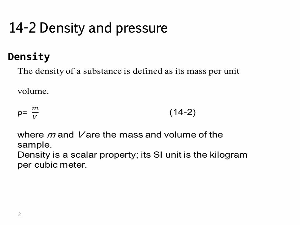
Density

3
4
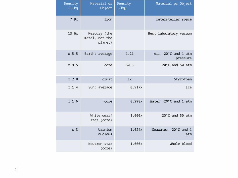
Density ((kg/
Material or Object
Density(kg)/
Material or Object
7.9x Iron Interstellar space
13.6x Mercury (the metal, not the planet)
Best laboratory vacuum
5.5 x Earth: average 1.21 Air: 20°C and 1 atm pressure
9.5 x core 60.5 20°C and 50 atm
2.8 x crust 1x Styrofoam
1.4 x Sun: average 0.917x Ice
1.6 x core 0.998x Water: 20°C and 1 atm
White dwarf star (core)
1.000x 20°C and 50 atm
3 x Uranium nucleus 1.024x Seawater: 20°C and 1 atm
Neutron star (core) 1.060x Whole blood
5
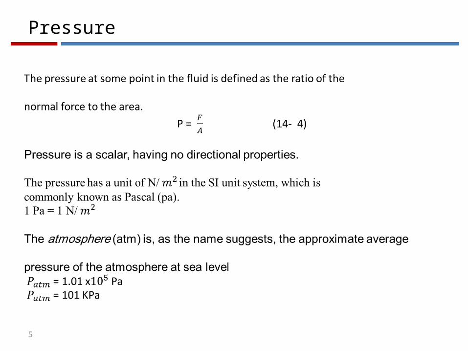
Pressure
6

7
As every diver knows, the pressure increases with depth below the air–water
interface. The diver’s depth gauge, in fact, is a pressure sensor much like that of
Fig. 14-1b. As every mountaineer knows, the pressure decreases with altitude as
one ascends into the atmosphere. The pressures encountered by the diver and the
mountaineer are usually called hydrostatic pressures, because they are due to fluids
that are static (at rest). Here we want to find an expression for hydrostatic pressure as function of depth or altitude.

8

9
Let us look first at the increase in pressure with depth below the water’s
surface. We set up a vertical y axis in the tank, with its origin at the air–water
interface and the positive direction upward. We next consider a water sample
contained in an imaginary right circular cylinder of horizontal base (or face) area
A, such that y1 and y2 (both of which are negative numbers) are the depths below
the surface of the upper and lower cylinder faces, respectively.
Figure 14-2e shows a free-body diagram for the water in the cylinder. The water
is in static equilibrium; that is, it is stationary and the forces on it balance. Three
forces act on it vertically: Force acts at the top surface of the cylinder and is due
to the water above the cylinder (Fig.14-2b). Similarly, force acts at the bottom (surface of the cylinder and is due to the water just below the cylinder (Fig.14-c
the gravitational force on the water in the cylinder is represented by m:g, where m is the mass

10
of the water in the cylinder (Fig.14-2d).The balance of these forces is written as
F 2 = F 1 + mg. (14-5)
But , F1 = p1A and F2 = p2A. (14-6) ,
m = ρV where the cylinder’s volume V is the product of its sur face area A and its height y1 -y2 .
Thus m is equal to ρA (y1-y2) .
Substituting this and Eq. 14-6 into Eq. 14-5, we find p2A = p1A + ρAg (y1 -y2)
or p2 = p1 +ρg (y1 - y2). (14-7)
This equation can be used to find pressure both in a liquid (as a function ofdepth) and in the atmosphere (as a function of altitude or height). For the former,suppose we seek the pressure p at a depth h below the liquid surface. Then wechoose level 1 to be the surface, level 2 to be a distance h below it (as in Fig. 14-3),
11
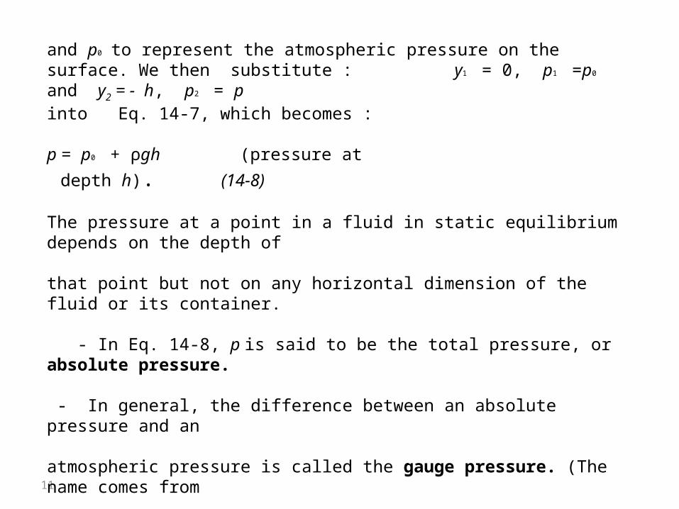
and p0 to represent the atmospheric pressure on the surface. We then substitute : y1 = 0, p1 =p0 and y2 = - h, p2 = p
:into Eq. 14-7, which becomes
p = p0 + ρgh (pressure at depth h). (14-8)
The pressure at a point in a fluid in static equilibrium depends on the depth of
that point but not on any horizontal dimension of the fluid or its container.
- In Eq. 14-8, p is said to be the total pressure, or absolute pressure. - In general, the difference between an absolute pressure and an
atmospheric pressure is called the gauge pressure. (The name comes from
the use of a gauge to measure this difference in pressures.)
- For the situation of Fig. 14-3, the gauge pressure is ρgh.
12
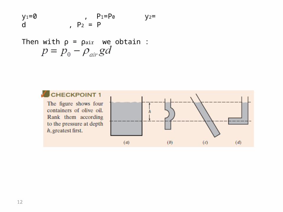
y1=0 , P1=P0 y2= d , P2 = P
Then with ρ = ρair we obtain :
13
14
14-5 Measuring Pressure
The Mercury Barometer
Figure 14-5a shows a very basic mercury barometer, a device used to measure
the pressure of the atmosphere. The long glass tube is filled with mercury and
inverted with its open end in a dish of mercury, as the figure shows. The space
above the mercury column contains only mercury vapor, whose pressure is so
small at ordinary temperatures that it can be neglected.
We can use Eq. 14-7 to find the atmospheric pressure p0 in terms of the
height h of the mercury column. We choose level 1 of Fig. 14-2 to be that of the
air–mercury interface and level 2 to be that of the top of the mercury column,

15
as labeled in Fig. 14-5a.We then substitute into Eq. 14-7, we get
y1= 0, p1 = p0 and y2 = h, p2 = 0
p0 = ρgh
ρ is the density of the mercury
1 atmosphere = patm =760 mm Hg
16
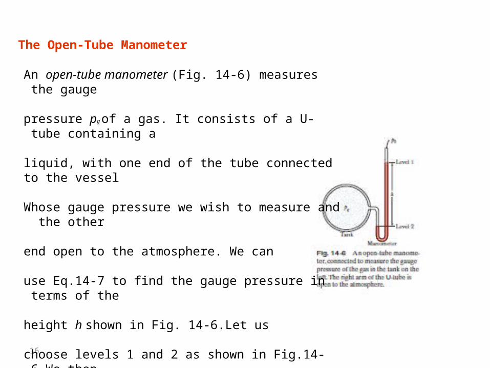
An open-tube manometer (Fig. 14-6) measures the gauge
pressure pg of a gas. It consists of a U- tube containing a
liquid, with one end of the tube connected to the vessel
Whose gauge pressure we wish to measure and the other
end open to the atmosphere. We can
use Eq.14-7 to find the gauge pressure in terms of the
height h shown in Fig. 14-6.Let us
choose levels 1 and 2 as shown in Fig.14-6.We then
:substitute y1 = 0, p1=p0 and y2= - h , p2 =p
The Open-Tube Manometer

17
Pg = p- p0 =
Where is the density of the liquid in the tube.
The gauge pressure pg is directly proportional to h .
The gauge pressure can be positive or negative .
14-6 Pascal’s Principle
Pascal’s law :
A change in the pressure applied to an enclosed incompressible fluid is transmitted
undiminished to every portion of the fluid and
to the walls of its container.
into Eq. 14-7, finding that :
18
in Fig. 14-7.The cylinder is fitted with a piston on which a container of lead
shot rests. The atmosphere, container, and shot
exert pressure pext on the piston and thus on the liquid .
The pressure p at any point P in the liquid is then:
p = pext + ρgh (14-11)
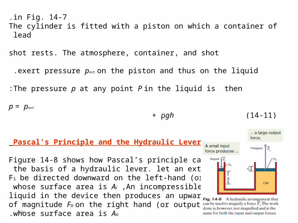
Pascal’s Principle and the Hydraulic Lever
Figure 14-8 shows how Pascal’s principle can be madethe basis of a hydraulic lever. let an external force
Fi be directed downward on the left-hand (or input) i
whose surface area is Ai ,An incompressible liquid in the device then produces an upward forceof magnitude Fo on the right hand (or output) pistonwhose surface area is Ao.
19
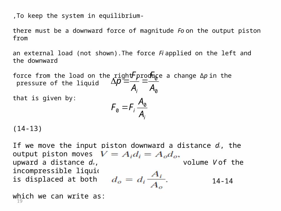
-To keep the system in equilibrium,
there must be a downward force of magnitude Fo on the output piston from
an external load (not shown).The force Fi applied on the left and the downward
force from the load on the right produce a change ∆p in the pressure of the liquid
:that is given by
(14-13)
If we move the input piston downward a distance di, the output piston movesupward a distance do, such that the same volume V of the incompressible liquidis displaced at both pistons. Then
:which we can write as
ii
i
i
A
AFF
A
F
A
Fp
00
0
0
14-14
20
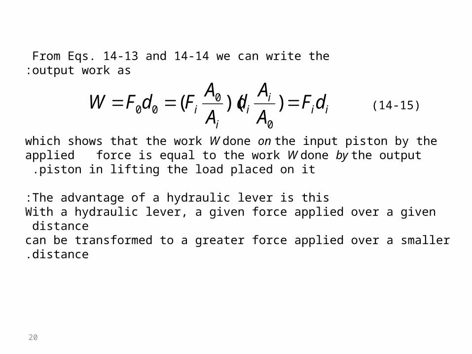
From Eqs. 14-13 and 14-14 we can write the output work as:
which shows that the work W done on the input piston by the applied force is equal to the work W done by the output piston in lifting the load placed on it .
The advantage of a hydraulic lever is this:With a hydraulic lever, a given force applied over a given distance can be transformed to a greater force applied over a smaller distance.
iii
ii
i dFA
Ad
A
AFdFW ))((
0
000 (14-15)

21
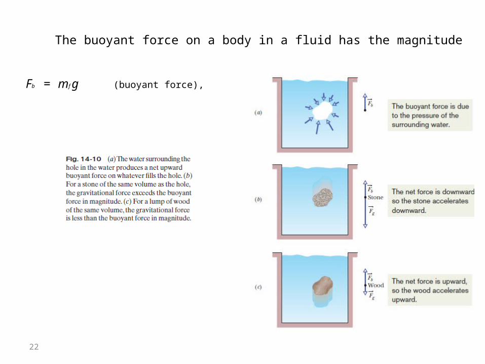
14-7 Archimedes’ Principle:Archimedes’ principle state that
When a body is fully or partially submerged in a fluid, a buoyant force Fb from thesurrounding fluid acts on the body. The force is directed upward and has a magnitudeequal to the weight mf g of the fluid that has been displaced by the body .
-This net upward force is a buoyant force . It exists because the pressure inthe surrounding water increases with depth below the surface. Thus, the pressurenear the bottom of the sack is greater than the pressure near the top, which meansthe forces on the sack due to this pressure are greater in magnitude near the bottom of the sack than near the top.
22
The buoyant force on a body in a fluid has the magnitude
Fb = mf g (buoyant force), (14-16)
23
Floating
When a body floats in a fluid, the magnitude Fb of the buoyant force on the
body is equal to the magnitude Fg of the gravitational force on the body.We can write this statement as
Fb =Fg (floating). (14-17)
From eq.(14-16) : then Fb = mf g. (14-18)
Apparent Weight in a Fluidif we measure the weight of stone under water,the upward buoyant force on the stone from the water decreases the reading. The apparent weight of a body on which a buoyant force acts is related to its actual weight by:
actual weight) – magnitude of buoyant force) )= ( (apparent
weight
weightapp = weight - Fb. (14-19)

24
25
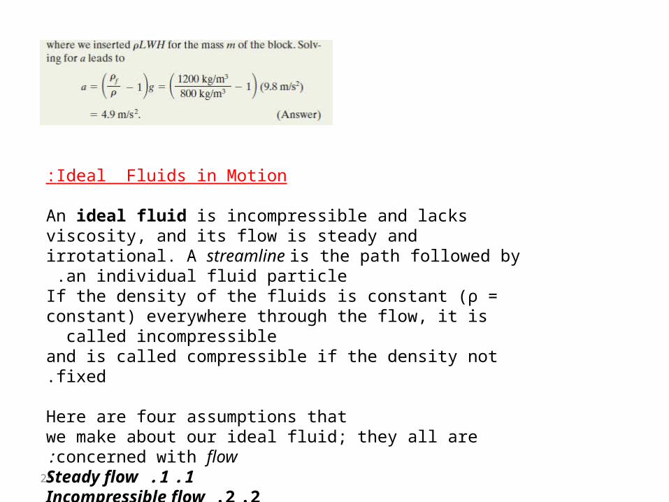
Ideal Fluids in Motion:
An ideal fluid is incompressible and lacks viscosity, and its flow is steady and irrotational. A streamline is the path followed by an individual fluid particle .
If the density of the fluids is constant (ρ = constant) everywhere through the flow, it is called incompressible
and is called compressible if the density not fixed.
Here are four assumptions thatwe make about our ideal fluid; they all are concerned with flow:
.11 .Steady flow.22 .Incompressible flow
3 .Nonviscous flow4 .Irrotational flow

26
1 .Steady flow: In steady (or laminar) flow, the velocity of the moving fluid at any fixed point does not change with time.
.12 .Incompressible flow: We assume, as for fluids at rest, that our ideal fluid is incompressible; that is, its density has a constant, uniform value.
3 .Nonviscous flow: The viscosity of a fluid is a measure of how resistive the fluid is to flow; viscosity is the fluid analog of friction between solids. An object moving through a nonviscous fluid would experience no viscous drag force—that is, no resistive force due to viscosity; it could move at constant speed through the fluid
4 .Irrotational flow: In irrotational flow a test body suspended in the fluid will not rotate about an axis through its own center of mass.
27
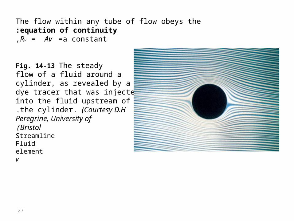
The flow within any tube of flow obeys theequation of continuity:RV = Av =a constant,
Fig. 14-13 The steadyflow of a fluid around acylinder, as revealed by adye tracer that was injectedinto the fluid upstream ofthe cylinder. (Courtesy D.H.Peregrine, University ofBristol)
StreamlineFluidelementv

28
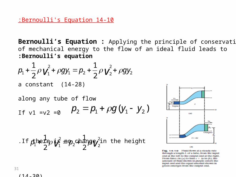
14-9 The Equation of Continuity:You may have noticed that you can increase the speed of the water emergingfrom a garden hose by partially closing the hose opening with your thumb.Apparently the speed v of the water depends on the cross-sectional area Athrough which the water flows.Here we wish to derive an expression that relates v and A for the steady flowof an ideal fluid through a tube with varying cross section, like that in Fig. 14-15.The flow there is toward the right, and the tube segment shown (part of a longertube) has length L.The fluid has speeds v1 at the left end of the segment and v2 atthe right end. The tube has cross-sectional areas A1 at the left end and A2 at theright end. Suppose that in a time interval t a volume V of fluid enters the tubesegment at its left end (that volume is colored purple in Fig. 14-15).Then, becausethe fluid is incompressible, an identical volume V must emerge from the rightend of the segment (it is colored green in Fig. 14-15).
v=A x=A v t
equation of continuity A1v1=A2v2

29
This relation between speed and cross-sectional area is called the equation ofcontinuity for the flow of an ideal fluid. It tells us that the flow speed increaseswhen we decrease the cross-sectional area through which the fluid flows.

30
31
14-10 Bernoulli's Equation:
Bernoulli’s Equation : Applying the principle of conservationof mechanical energy to the flow of an ideal fluid leads toBernoulli’s equation:
a constant (14-28)
along any tube of flow
If v1 =v2 =0
If there is no change in the height.
( 14-30)
2
2
221
2
11 2
1
2
1gypgyp vv
vv pp2
22
2
11 2
1
2
1
)( 2112 yygpp
32
33