14 eighteen-pulse ac-dc converter for harmonic mitigation in vector controlled induction motor d
TRANSCRIPT

IEEE PEDS 2005
Eighteen-Pulse AC-DC Converter for HarmonicMitigation in Vector Controlled Induction Motor
Drives
Bhim Singh, Senior Member, IEEE, G.Bhuvaneswari, Vipin Garg, Member, IEEESenior Member, IEEE Electrical Engg. Department, Indian Railways
Department of Electrical Engg, I.I.T.Delhi, Northem RailwayNew Delhi, India New Delhi, India
E-mail: [email protected], [email protected] E-mail: [email protected]
Abstract-This paper presents a novel autotransformer based example. But the kVA rating of the transformer is 1.03 PO,eighteen-pulse ac-dc converter with reduced kVA rating, feeding where PO is the active power drawn by the converter [6]. Tovector controlled induction motor drives (VCIMD's) for power reduce the transformer rating, autotransformer basedquality improvement at the point of common coupling (PCC). multipulse ac-dc converters of reduced rating have beenThe proposed 18-pulse ac-dc converter is suitable for retrofit reported in the literature [3]. For applications where theapplications, where presently a 6-pulse diode bridge rectifier is demand for harmonic current reduction is more stringent, anbeing used. The proposed harmonic mitigator eliminates 5"h, 7" 18-pulse ac-dc converter is enerall referred. This converter11 and 13th harmonic currents, thereby improving the power ps gene y preferred.Thisconverterquality at ac mains. A set of different power quality parameters is more economical than the 24-pulse ac-dc converter, whilefor a VCIMD fed from the proposed 18-pulse ac-dc converter are being more effective than the 12-pulse ac-dc converter.computed to observe its performance. The effect of load variation Autotransformer based 18-pulse ac-dc converters have beenon VCIMD is also studied to observe the effectiveness of the reported in [7] for reducing the THD of ac mains current.proposed harmonic mitigator. The simulated results are verified However, the dc-link voltage is higher, making the schemeon the prototype autotransformer designed and developed in the non applicable for retrofit applications. Hammond [8] haslaboratory. A comparative performance of different ac-dc proposed a new topology, but the transformer design is veryconverters based on eighteen-pulse rectification have also been c T spresented to demonstrate the performance of the proposed AC- complex Toswtoplofy the t1ansformer design.Paice [9] hasDC converter feeding VCIMD. reported a new topology for 18-pulse converters. But the THD
Keywords- Autotransformer, MATLAB, multipulse AC-DC of ac mains current with this topology is around 8% at fullconverter, power quality improvement, VCIMD. load. Kamath et.al. [11] have also reported an 18-pulse
converter, but THD of ac mains current is high even at fullI. INTRODUCTION load (6.9%) and as load decreases the THD increases further
The use of induction motors has increased in industrial (13.1%THD at 50% load).applications dueto motheirshadvans suchased improvedua In this paper, a novel autotransformer based 18-pulse ac-dc
applications due to their advantages such as improved converter (Topology 'D'), which is suitable for retrofitefficiency, ruggedness, reliability and low cost. For variable applications, where presently 6-pulse converter is being used,speed drives, dc motors have been used until now because of referred as Topology 'A', shown in Fig. 1, have been proposedtheir flexible characteristics. To incorporate the flexible tofeed VCIMD. T hops a- converter resuscharacteristics of a dc motor into an induction motor, vector elimination of 5th, 7th, 11fi and 13d harmonics. A set ofcontrol technique is adopted [1] as a widely accepted choice. tabulated rsl givin th comp arion ifferet ow
Normally ac-dcpwer converter feding power to thtabulated results giving the comparison of different powerNormally ac-dc power converter feeding power to the quality parameters is presented for a VCIMD fed from an
VCIMD consists of a 6-pulse diode bridge rectifier, an energy existing 6-pulse ac-dc converter and different 18-pulse ac-dcstorage element at dc link, a 3-phase voltage source inverter convertersMro,te ffe riat on ariou(VSI) and an induction motor. The diode bridge rectifier pow terqualit id es is a osuid vtiod ostra thesuffers from operating problems such as poor power factor, effectiveness of proposed 18-pulse ac-dc converter feedinginjection of harmonic currents into the ac mains etc. In order VCIMDvto prevent the harmonics from affecting the utility lines A of pt oA laboratory prototype of the proposed autotransformer iSnegatively, an IEEE Standard 519 [2] has been reissued in designed and developed ansd different tests have been carried1992 giving clear limits for voltage and current distortions. otovaitehewrng ftepoosd amnc
Several methods based on the principle of increasing the mitigator. The test results are found to be in close agreementnumber of rectification pulses in ac-dc converters have been wt h iuae eut ne ifrn prtn nreported in the literature [3-12]. The conventional wye-delta loading conditions.transformer based 12-pulse rectification scheme is one such
0-7803-9296-5/05/$20.00 © 2005 EEE 1514

IGBT Based Inverter i
d~~~~~~~ ~ ~TreePhse
ids iqC C s 26LbbelJodeBridgeRahiliem
_ Fig.2 Autotransformer (with phase shift of ±4O°) based 18-pulse harmonicSpee Cotroler'r stimrlator Fil mnitigator fed VCI4D (Topology 'B').
Fig.l Six-pulsediode bridge rectifier fedvector controlledi nductionmotor drive (Topology 'A'). V. d
II. DIFFERENT CIRCUrr CONFIGURATIONS OF EIGHTEEN-C II , CIV. + lPULSE AC-DC CONVERTERS 3b9ZDs ||>||4v|t
An autotransformer based n-pulse ac-dc converter operates 4= :~ iL I ¢ IGBTBaiedhveIB dr
on the principle of harmonic elimination. The minimum orderof harmonics are nK±+1, where K is a positive integer and n is Athe number of rectification pulses per cycle of fundamental AZNIGIvoltage. For harmonic elimination, the required mnimum r Lphase shift is given by [3]: P u b e D E d e Bridge RisPhase shift = 600/ Number of six-pulse converters Fig.3 Autotransforner (with phase shift of±200) based 18-pulseTo achieve an 18-pulse rectification, three sets of balanced 3- harmonic mitigator fed VCIMD (Topology 'C').
phase line voltages are to be produced, which are either 20 or400out of phase with respect to each other. Fig.2 shows the V X a! Vschematic diagram of an 18-pulse ac-dc converter with a phase 8shift of +400 and -4p0, referred as Topology 'B'. The voltages 'A. 7produced by the autotransformer Va' , Vb' , Vc' are at +400 ,with respect to supply voltages Va, Vb and Vc, where as the V a > bother set of voltages Va" , Vb", Vj' are at ~40° with respect to C< (]supply voltages. Similarly, Fig.3 shows the schematic diagramvvof an 18-pulse autotransformer based ac-dc converter with aphase shift of +200 and -20o. This topology is referred as VbTopologyf'C'. are n
A. Proposed Eighteen Pulse AC-DC ConverterbHere, ± 200 phase shift is used to reduce the size of Fig. 4 Proposed autotransformer winding connection diagram.
magnetics and the magnitude of these line voltages should beequal to each other to result in symmetrical pulses and reduced produced. The number of turns required for +200 and -20°ripple in output dc voltage. The design of the suitable phase shift are calculated as follows. Consider phase 'a'autotransformer for the proposed eighteen-pulse ac-dc voltages as:converter, referred as Topology 'D' is given here. Va' = Va +KiVca - K2 VbC (1)
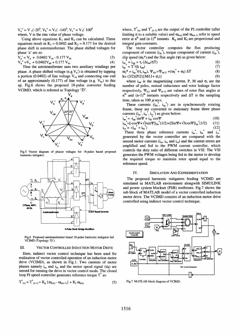
Fig.4 shows the winding diagram of the proposed ac-dc Va"=Va+ KiVab + K2VbC (2)converter. Fig.5 shows the phasor diagram of different phase Assume the following set of voltages:voltages of the proposed autotransformer for achieving an 18- vv=vz0, Vb=VZ-1200, = VZ1200,pulse rectification. From the supply voltages, two sets of 3- Vab= 1.732VZ300,vb = V-900,Vc5=VZ-300phase voltages (phase shifted through +200 and -20) are Va' = V Z20, Vb' = VZa000, VJ = VZ1400
1515
Va" = V Z-200, Vb" = VZ -1400, Vc" = VL 1000 where, T*(n) and T(n-l) are the output of the PI controller (afterwhere, V is the rms value of phase voltage. limiting it to a suitable value) and 4e(n) and 4e(n-1) refer to speed
Using above equations K1 and K2 can be calculated. These error at nth and (n-l)ff instants. Kp and KI are proportional andequations result in K, = 0.0402 and K2 = 0.177 for the desired integral gain constants.phase shift in autotransformer. The phase shifted voltages for The vector controller computes the flux producingphase 'a' are as: component of current (id,), torque component of current (iqs*),Vat = Va + 0.0402 Vca - 0.177 Vbc (3) slip speed (co2*) and the flux angle ('v) as given below:Va =Va + 0.0402Vab + 0. 177 Vbc (4) ids* = imr + tr (Ajimr/AT) (6)
Thus the autotransformer uses two auxiliary windings per iqs* = T*/(k imr) (7)phase. A phase shifted voltage (e.g.Va') is obtained by tapping (02* = iqs*/(Tr imr), P(n) =T(n-l) +((02* + (or) AT (8)a portion (0.0402) of line voltage Vca and connecting one end k= (3/2)(P/2){M/(1+ Gr)} (9)of an approximately (0.177) of line voltage (e.g. Vk) to this where i,,r is the magnetizing current, P, M and Or are theap. Fig.6 shows the proposed 18-pulse converter feeding number of poles, mutual inductance and rotor leakage factorVCIMD, which is referred as Topology 'D'. respectively, P(n) and P(n-l) are values of rotor flux angles at
Va nth and (n-i)th instants respectively and AT is the samplingVa'X% Va' time, taken as 100,u secs.
\/ a/ These currents (ids, iqs*) are in synchronously rotating
V /6\200 200)<\ frame, these are converted to stationary frame three phaseca / > _/ \ currents (i.S, ibs, i,, ) as given below:
/ \/\ Vab iaS = -i~~q si + id5cos'P (10)las =-1 sinT (VcX \ L \ Vb' ibs=[-cosT+43sinW]ids*(1/2)+[SinP+i3cosT]iqs*(1/2) (11)
bi / / \\ 9 ics = -(ias + ibs) (12), / \\y These three phase reference currents ias, ibs and iCs
V - \7 Vbc \)/ b generated by the vector controller are compared with thesensed motor currents (ias, ibs and ics) and the current errors are
C b amplified and fed to the PWM current controller, whichFig.5 Vector diagram of phasor voltages for 18-pulse based proposed controls the duty ratio of different switches in VSI. The VSIharmonic mitigator. generates the PWM voltages being fed to the motor to develop
E z 4+ the required torque to maintain rotor speed equal to thereference speed.
II IV. SIMULATION AND EXPERIMENTATIONThe proposed harmonic mitigators feeding VCIMD are
+ simulated in MATLAB environment alongwith SIMULINKvb' and power system blockset (PSB) toolboxes. Fig.7 shows the
3ll lfi sub block of MATLAB model of a vector controlled inductionv1 1 1 S rS 0<1c- A tVcIM motor drive. The VCIMD consists of an induction motor drive
controlled using indirect vector control technique.3Pfws6s Be46RV,I60HIZ a! +
Fig.6 Pro dAutotransfom bd 1ul harGc mtigatorfhe DdyVCIMD (Topology 'D').
6 ~ ~ ~ ~ f PusDkeBig efif
III. VECTOR CONTROLLED INDUCTION MOTOR DRIVE kr l l lHere, indirect vector control technique has been used for Ret Spe wr -0Wfs
realization of vector controlled operation of an induction motor P 0iRfI
drive (VCIMD), as shown in Fig. 1. Two curfents of motor S5p |c TOe
phases namely iaS and ib, and the motor speed signal (x) are ret Cum wwtXsensed for running the drive in vector control mode. The closedIIloop PIspeed controller generates reference torqueT5a:LI2
Tn = T5(n-l) + Kp { (Oe(n) - (O)e(n-1)1} + KI °~e(n) (5) Fig.7 MATLAB block diagram of VCIMD.
1516

Autotmmnfor.uer Diode Rectifiers s-106s
Inter pk.e trausformner
Fig.8 MATLAB block diagram of proposed harmonic mitigator fed VCIMD.
Fig.8 shows the MATLAB model of the proposed harmonic A.Atrasomrwh+40nd4OPaeShfBsdmitigator based on 18-pulse rectification feeding a VCIMD to AC-DC Converter (Topology 'B')simulate its performance. To validate the simulation results, a The simulation results of an autotransformer (with phaseprototype model of the proposed 18-pulse ac-dc converter shift of +400 and -40°) based ac-dc converter fed VCIMD areconsisting of an autotransformer suitable to produce the phase shown in Table-I. The THD of supply current at full load asshifted voltages, interphase tranlsformer and diode rectifiers shown in Table-I. The voltage at dc link is 713V at fullhas been developed in the laboratory and different tests have loadagainst 604V in a 6- pulse diode bridge rectifier fedbeen conducted. VCIMD. Thus this topology cannot be used in retrofit
applications.V. RESULTS AND DISCUSSION
The performance of the proposed harmonic mitigator 0alongwith the VCIMD have beenAsimulated for the systemlof 20-which the data are given in Appendix. Fig. 9 shows thestartinlg performance and load perturbation on the VCIMD fed -by a 6-pulsediode bridge rectifier (Topology 'A'). It shows the -20k------ 8-----,supply voltage v0, supply current is, rotor speed 'ox' (in elect. -4QI,v -,4,4 OW09 0905 091 0915 092 0925 093 0935 094 0945rad /sec), three-phase motor currents isab, motor developed ieaatorque Te' (in N-in) and DC link voltage vdc (V). Fig.10 shows = T Ttime(s) lthe supply current waveform alongwith its harmonic spectrum °. 80Lj ....at full load. The THD of ac mains current at full load is £ 6011, THDf 31.6/0.
Fig. 1 1. Moreover, the power factor at full load is 0.935, which SO40deteriorates to 0.85 as the load on VCIMD is reduced, thus IMD
c iDettPIIM~c L I m
requiring the need of power quality improvement at ac mains. e 0 i4l0 8 10 1200Frequency (Hz)
EMTA blc diagrai n oA h ^ ^A h A:fiprAoAposedh A Ahamonic mgAtrfe aaMDFig. 10 AC mains current waveform of VCMD fed by 6-pulseF:i8swsMthe MATLAB Modeloftheproposed r i dioderectifieralong withits4haonic spectrm at ful load.
ons200 fan aoa? -nsfor Asuale to" _ u te ps sw in T The D of p ly e at
ted vlt h r d Io If sow i_ e a t c n s 7 a
ben codctd VCMD Thus this toplog canno 144 used inreroi
- -20a tirne (s)400 1 g42 nTs n A n n n 7
z200 .aX1....!]X -0 ... ...,. . --i-----------
>~~~~~~~~~~~~~~~~~~0
Io ..t0.20a3 0.4 0i. 0.6 0.7s 20 . L
startingimperormnc an loa petrbto on th VCM fed _l l2 0- ..... ) ------
Fig.9 Dynamic response of 6-pulse diode rectifier fed VCIMDwith load perturbation. - Fig. 11 AC mains current waveform of VCIMD fed by 6-pulse diode
rectifier along with its harmonic spectrum at 20% of full load.
1517
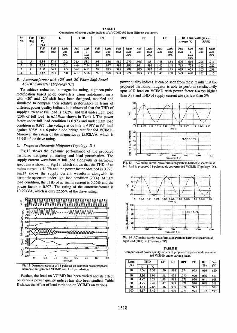
TABLE IComparison of power quality indices of a VCIMD fed from different converters
Sr. Top Ti) THD DF DPF PF CF DC Link Voltage(Vd,)No. olog Vs Average (V) RF(%)
Y (%)Full Full Light FuU I-igh Full Light FuU Light Full Light Ful Light Full Ligh Full Lightload load load load t load load load load load load load load load t load load
20%l load 20% 20% 20%1c 20% | load 20,%__ _ ___ _ _ 20% __ _ __ _ _ __ _ _ 20% _ __
1. A 6.84 57.3 17.2 31.4 58.1 .95 .866 .982 .979 .935 .85 1.48 1.84 606 616 .225 .2112. B 2.25 55.5 15.1 4.64 7.54 .99 .997 .992 .996 .991 .994 1.45 1.48 713 728 .103 .0223. C 2.00 54.3 14.5 3.62 6.11 .99 .973 .998 .988 .973 .987 1.41 1.45 619 635 .103 .0394. D 3.42 55.3 15.0 4.17 5.56 .99 .998 .974 .974 .973 .973 1.45 1.50 599 620 .132 .016
B. Autotransformer with +20° and -20°Phase Shift BasedB.Autotransfonveer wiThopologynd'C 0'Phase Shift Based power quality indices. It can be seen from these results that theAC-DC Converter (Topology 'C') proposed harmonic mitigator is able to perform satisfactorilyTo achieve reduction in magnetics rating, eighteen-pulse upto 40% load on VCIMD with power factor always higher
rectification based ac-dc converters using autotransformers than 0.97 and THD of supply current always less than 5%with +200 and -200 shift have been designed, modeled andsimulated to compare their relative performance in terms of 100different power quality indices. It is observed that the THD of 5o --- ------ . ---
supply current at full load is 3.62%, and that under light load o(20% of full load is 6.11%,as shown in Table-I. The powerfactor under full load condition is 0.973 and under light load - -- -condition is 0.987. The voltage at dc link is 619V at full load 19.1 110s 1.11 1.115 1.12 1.125 1.13 1.135 1.14 1.145 1.15against 606V in a 6-pulse diode bridge rectifier fed VCIMD. E time (s)Moreover the rating of the magnetics is 15.92kVA, which is 834.9% of the drive rating. CD THDi- 4.17%
C. Proposed Harmonic Mitigator (Topology 'D') i 2 L-Fig.12 shows the dynamic performance of the proposed 400 6
harmonic mitigator at starting and load perturbation. The ° 200 400 Goo 00 1000 1200supply current waveform at full load alongwith its harmonic Frequency (Hz)
spectrum is shown in Fig. 13, which shows that the THD of ac Fig. 13 AC mains current waveform alongwith its harmonic spectrum atmains is 417%adtheoweractorobtaindis973
full load in proposed 18-pulse ac-dc converter fed VCIMD (Topology 'D').mains current is 4.17% and the power factor obtained is 0.973.Fig. 14 shows the supply current waveform alongwith itsharmonic spectrum under light load condition (20%). At light 20 ------ - - --- - ------------
load condition, the THD of ac mains current is 5.56% and the 10power factor is 0.973. The rating of the autotransformer is 010.29kVA, which is only 22.55% of the drive rating.
-20 ------ -- .---------- ----1
1.5 1 505 1.51 1.515 1.52 1 525 1.53 1.535 1.54 1.545 1.65~~~~~~~~~~~~~~~~~~~~~~~~~~~~~~~~~~~~~~~time(s)
n_ n_n_ n_ An__nz_n___n 8100
50
'°° _2 I-----------------------------------L-----------*--------*.a)o 01 I) II01 0I * n*840
t0 200 01 n2v 10n 0s fls 0,n67 08 E °0 200 400 60-0-01---00-1---20-0*
-50 ~~~~ ~ ~ ~ ~ ~ ~ ~ ~ ~~
~~x,v~)vvv~v.,. Frequency (Hz)
n 0n7 n w 0 07 n Fig. 14 ACmainscurrentwaveformalongwithitsharmonic spectrumnat;*400/ q___________ light load (20%) in (Topology 'D').
E700 (1 02 01 gA^ s n, 0,7 0l8 |TABLEII600 ~~~~~~~~~~~~~~~~~Comparisonof power quality indices of proposed 18-pulse ac-dc converter
> eiw ' j ffi ~~~~~~~~~~fedVCIIMD under varying loads.0.1 0.2 0.3 0.4 0. 06 07 08Time(Sec) |Load | Till | CF |DF |DPF |PF |RF |Vdc
Fig.12 Dynamic response ofl18-pulse ac-dc converter based proposed |(%) |~Is|V,1 (%) |(V)|hamonic mitigator fed VCIMD with load perturbation.| 20n556 131 150 998 |.974 .973 .016 620
Further, the load onVCIMD has been varied and its effect |40 |5.10 1.96 |1.48 |.998 .970 .970 .036 |611|on various power quality indices has also bee nstudied.Table Fg501 4.92m 2.24 1e.48 m.998a .971i .970 .041 l608TY * s * v . | ~~~~~~~~~~601 4.751 2.47 1.147 1.999 1.97 11 .9701 .048 618lISows the effect of load variation on VCIMD on vaous |80 |444 |288 146 .999 .974 .973 |.101 603
100 4.17 3.42 1.45 .999L 974 .973 .132 599
1518

Table I shows a comparative study of different power VI. CONCLUSIONSquality indices of a VCIMD fed from a 6-pulse converter and A novel autotransformer based eighteen-pulse ac-dcdifferent 18-pulse converters. The eighteen-pulse converter converter has been designed and modeled with a VCIMDwith +400 and -400 phase shift, gives a higher dc link voltage load. The proposed harmonic mitigator has been observedthan a six-pulse diode bridge rectifier. So this topology can not suitable for retrofit applications with variable frequencybe used in retrofit applications. The autotransformer with +200 induction motor drives operating under varying loadand -20° phase shift can be used in retrofit applications, but the conditions. The performance of the proposed harmonicrating of the magnetics is 34.9% of the drive rating. The mitigator fed VCIMD under varying load conditions is foundproposed autotransformer based eighteen-pulse ac-dc to be satisfactory. The proposed harmonic mitigator hasconverter gives the same dc link voltage as of a six-pulse resulted in reduction in rating of the magnetics leading to thediode bridge rectifier, making it suitable for retrofit saving in overall cost of the drive. The observed performanceapplications. Moreover, in the proposed converter (Topology of the proposed harmonic mitigator has demonstrated the'D'), the rating of the autotransformer is 8.75kVA. It also capability of this converter to improve the power qualityneeds a small rating interphase transformer of 1.536kVA, indices at ac mains in terms ofTHD of supply current, THD ofresulting in total magnetics of 10.29kVA rating, which is only supply voltage, power factor and crest factor. On the dc link22.55% of the drive rating. side too, there is a remarkable improvement in ripple factor of
dc link voltage.D. Experimental Validation ofProposed AC-DC Converter
Eighteen-pulse rectification has been achieved by the VII. APPENDIxdesigned and developed autotransformer. Different tests have Motor and Controller Specifications:been carried out to verify the simulated results. The test results Three-Phase Squirrel Cage Induction Motor -SOhphave been recorded using Fluke make power analyzer model (37.3kW), 3-Phase, 4 Pole, Y- connected, 460 V, 60 Hz, R, =43B on the developed prototype. The harmonic spectrum of ac 0.087 ohms, R, = 0.228 ohms, XIS = 0.3016 ohms, Xlr =mains current alongwith the waveform of supply voltage (V5) 0.3016 ohms, Xm =13.0819 ohms, J= 1.662 kg-m2.and supply current (Is) at full load is shown in Fig. 15. The PI Controller: Kp = 45.0, Ki = 0.1, DC Link parameters: Ld =THD of supply current at full load is 5%. These results show 0.1mH, Cd = 3200jsF.an agreement with the simulated results Magnetics ratings: Autotransformer Rating 8.75kVA,
Interphase Transformer 1.53kVAr_ cnITHD1 411l_.J %r 4_20 Hz *VIm. REFERENCES
10435A 1034A [1] P.Vas, Sensorless vector and direct torque control, Oxford UniversityI1 9 9 oo o- Press, 1998.1.3 99,_0 07r [2] IEEE Guide for harmonic control and reactive compensation of Static0 * Power Converters, IEEE Std. 519-1992.
- 4 [3] D. A. Paice, Power Electronic Converter Harmonics: MultipulseMethodsfor Clean Power, New York, IEEE Press 1996.
r ([4] S.Martinius, BsHalimi and P.A.Cahono, "A transformer connection formultipulse rectifier applications," Proc. Int. Conf. Powercon, Oct.2002,
4-.
vol.2, pp. 1021-1024.
[5] M.H. Shwehdi, A.H. Mantawy and HRH Al-Bekhit, "Solving theharmonic problems produced from the use of adjustable speed drives in
0 industrial oil pumping field," Proc. Int. Conf Powercon, Oct.2002,1 5 9 13 17 21 25 29 33 37 41 45 49 vol.lpp. 86-92.5Mtljw| [6] S. Choi, P.N. Enjeti and Ira J. Pitel, "Polyphase transformer
l arrangements with reduced kVA capacities for harmonic current............................................................................................ ...... reduction in rectifier type utility interface," IEEETrans. on Power
f\ * ,V, Pt . A Electronics, Vol.11, No. 5, Sept.1996, pp. 680-689.[7] D.A. Paice, "Multipulse converter system", U.S. Patent No. 4876634, 24
* ......... ...[ October, 1989.
....t ;.. ;- , ,; ss-- - * ** * *.......... [8] P.W.Hammond, "Autotransformer", U.S. Patent No. 5619407, 8Sti }? F ^}- $!, }. .th April,1997.
..... [9] D.A.Paice, "Transformers for multipulse AC/DC converters", U.S.Patent No. 6101113, 8 August, 2000.
L ' Ff \ t/ i. j \, .X%. [10] D.Zhou, L.Skibinski and N.N.Guskov, "Nine-phase transformer," U.S.4: --,-:-''i'''''':''''**i*Patent No. 6,249,443B1, June19, 2001.
...\ 0 * ... ;ts':\.......[11] G. R. Kamath, D. Benson and R. Wood, "A novel autotransformer basedsi>5,,/ \/ * $ * S * *;18- pulse rectifier circuit," in Proc., IEEE IECON'03, 2003, pp. 1122-
rn.100.U/ .......
/ 1127.iOO It-lOtiis5d I10 tAtfd iEi [12] F.J.Chivite-Zabalza, A.J.Forsyth and D.R.Trainer, "Analysis and
1 338 u 1 0 1 9 A= practical evaluation of an 18-pulse rectifier for aerospace applications,"in Proc. 2004, IEEE PEMD, Conf., pp. 338-343.
Fig. 15 Harmonic spectrum of supply current alongwith supply voltage andcurrent waveform at full load in proposed 18-pulse based ac-dc converter.
1519