14 system trrnsputers(u) naval i postgraduate … · mauricio de menezes cordeiro lieutenant,...
TRANSCRIPT
A-ftS" 593 DESIGN IMPLEMENTATION AND EVALUATION OF AN OPERATING 14r SYSTEM FOR A NETWORK OF TRRNSPUTERS(U) NAVALI POSTGRADUATE SCHOOL MONTEREY CA A 0 CORDEIRO
mhhhW1FED EEOh5/EEE
1111 1112-S1.8
:iI~ [fllffJ hIfl.6
MICROCOPY RESOLUTION TIST 'CHART
'p
*l . . ."

UPiC FILE CORI
NAVAL POSTGRADUATE SCHOOLMonterey, California
A DTIC",E'LEcTEI'x
THESIS
.5
5.
DESIGN, IMPLEMENTATION AND EVALUATION .,1OF AN OPERATING SYSTEM ,
FOR A NETWORK OF TRANSPUTERS .
by ,
Mauricio de Menezes/Cordeiro t
J..
June 1987 -
Thesis Advisor Uno R. Kodres.,A1s
,5
I,'8 aLECTI

UNCLASSIFIEDsicustry CLASSIFCAION OF THIS PAGE - / - '
REPORT DOCUMENTATION PAGEI& REPORT SECURITY CLASSIFICATION lb RESTRICTIVE MARKINGS
UNCLASSIFIED
Ja SECURITY CLASSIFICATION AUTHORITY I DISTRIBUTION/ AVAILABILITY Of REPORT
2b OECLASSIFICATIONIOO*NGRAOING SCHEDULE Approved for public release; bDistribution is unlimited.
4 PERFORMING ORGANIZATION REPORT NUMBER(S) S MONITORING ORGANIZATION RE.PORT NuV~BER(S)
6a NAME OF PERFORMING ORGANIZATION 6b OFFICE SYMBOL ?a NAME 0F MONITORING ORGANIZATION
Naval Postgraduate School 52Va9IaOe Naval Postgraduate School
6c ADORESS {Ciry. State. and ZIP Cod#) 7b ADORE SS (Coty, State. and ZIP Code)
Monterey, California 93943-5000 Monterey, California 93943-5000
8& NAME OF FUNDING iSPONSORING r8b OFFICE SYMBOL 9 PROCUREMENT INSTRUMENT IDENTIFICATION PIUM8ERO~RGANIZATION [(it applicabio)
8c ADDRESS (Cory. State, ad Io Code) 10 SOIJRCE OF FUjNDING NUMBERS
PROGRAM IPROJECT TASK~ hoRK _,NiTELEMENT NO NO NO ACCIESSOP NO
T~t.~(Iclde ecnt Cju,~ct~nl DESIGN, IMPLEMENTATION AND EVALUATION OF AN OPERATING
SYSTEM FOR A NETWORK OF TRANSPUTERS
* ~ESON~ ATHO(S) CORDEIRO, MAURICIO DE MENEZES
la RE; C;QPORT 3b T'M[ COVERED 114 DATE OF REPORT (Year M~onthi Dy) PAGjE (0,NrMaster's Thesis FROM TO j June 1987 (s163 -
6SLP-'I.E.ENTARY NOTATION
COSATI CODES 19 SUBJECT TERPAS (Continue on 'even#If dnqoceLujr and odenrl1y by block nlumber)
9 ELD JGROUP SUB GROUP Transputer,Operating System, OCCAM, TDS, Network,- I Concurrent Processing, Distributed System, Routing,
I Message Communications .or-
This thesis presents the Design, Implementation and Evaluation of an Operating
Svstemn for a Netwvork of Transputers, with miain 1 ocus on the Communication
Subsystem. It also introduces the novice to the Transputer Development Systcmn
(TDS), and suggests a sequence for developing applications.All the programs and examples presented In this thesis %vcre implemented in the
OCCAM I Programming Language, and using the Transputer lDevclopment S% stemi(TDS-D3600), running under the VAX,'VMS Operating Sy stemn at the alPostgraduate School (NPS).
iO 0~ y''3UON, AVAILABILITY OF ABSTRACT 21 ABSTRACT SECURITY CLASSIFICATION
CM _NCLAS55LFTE D/lNI.MItED Q SAME AS ROT 00TI USERS UNCLASSIFIEDIla %Am( OF RESPONSIBLE INDI~VIDUAL Jib TELEPHONE (Irsorude Aree Code)122c O~fIA S-M80t
Prof. KODRES, UNO R. (408) 646-2197 Code 52Kr
OD FORM 1473. 84 MARINAReIO a @.~ jIeIhI~ SECURITY CLASSIC-Al'ON Of '-.5 PAC
All other editions as0 obsoletet
% %

Approved for public release; distribution is unlimited.
Design, Implementation and Evaluationof an Operating System
for a Network of Transputers
by
Mauricio de Menezes CordeiroLieutenant, Brazilian Nav"
B.S., Brazilian Naval Academy, 1976
Submitted in partial fulfillment of therequirements for the degree of
MASTER OF SCIENCE IN COMPUTER SCIENCE
from the
NAVAL POSTGRADUATE SCHOOLJune 1987
Author: Q-A L47O)1'Mauricio de Mepezes qordeiro
Approved by: . /Le d(-t-'Uno R. Kodres, Thesis Advisor
Daniel L'. Davis, Sccond Rcader
Vincent V. Lon, Chairm"an,Department of /Computer Science
Knealc IThomas , sl,Dean of Information and
2
, %i
ABSTRACT
This thesis presents the Design, Implementation and Evaluation of an Operating -"
System for a Network of Transputers, with main focus on the Communication
Subsystem. It also introduces the novice to the Transputer Development System
(TDS), and suggests a sequence for developing applications.
All the programs and examples presented in this thesis were implemented in the
OCCAM I Programming Language, and using the Transputer Development System .-
(TDS-D600), running under the VAX/VMS Operating System at the Naval
Postgraduate School (NPS).
P d'
ACCe>' r I
lOT;i' , - -''
-'
3 -*1
a0

UV,
THESIS DISCLAIMER
The reader is cautioned that computer programs developed in this research may
not have been exercised for all cases of interest. While every effort has been made,
within the time available, to ensure that the programs are free of computational and
logic errors, they cannot be considered validated. Any application of these programs
without additional verification is at the risk of the user.
Many terms used in this thesis are registered trademarks of commercial products.
Rather than attempting to cite each individual occurrence of a trademark, all registered
trademarks appearing in this thesis are listed below the firm holding the trademark:
Digital Equipment Corporation, Maynard, MassachusettsVAX 11(780 Minicomputer
VMS Operating System
VT-220 TerminalVT- 100 Terminal
Digital Research, Pacific Grove, CaliforniaCP/M 86 Operating System
INMOS Group of Companies, Bristol, UK
Transputer
Occam
INMOS
IMS T414
IMS T800
TDS
OPS
Intel Corporation, Santa Clara, California
iSBC 86/12A Single Board Computer
Multibus
8086 Microprocessor
Microsoft Corporation, Bellevue, Washington
DOS Operating System
Xerox Corporation, Stanford, Connecticut
Ethernet
44
4i 4.~~ ~ ~~ ~- .. . ., . . -. .. . . .. ....--.-..... *.. -. . .*' . ,..,.-. ...................* .)....

Zenith Data Systems Corporation, St. Joseph, Michigan
Z-248 Microcomputer
5 -PIN
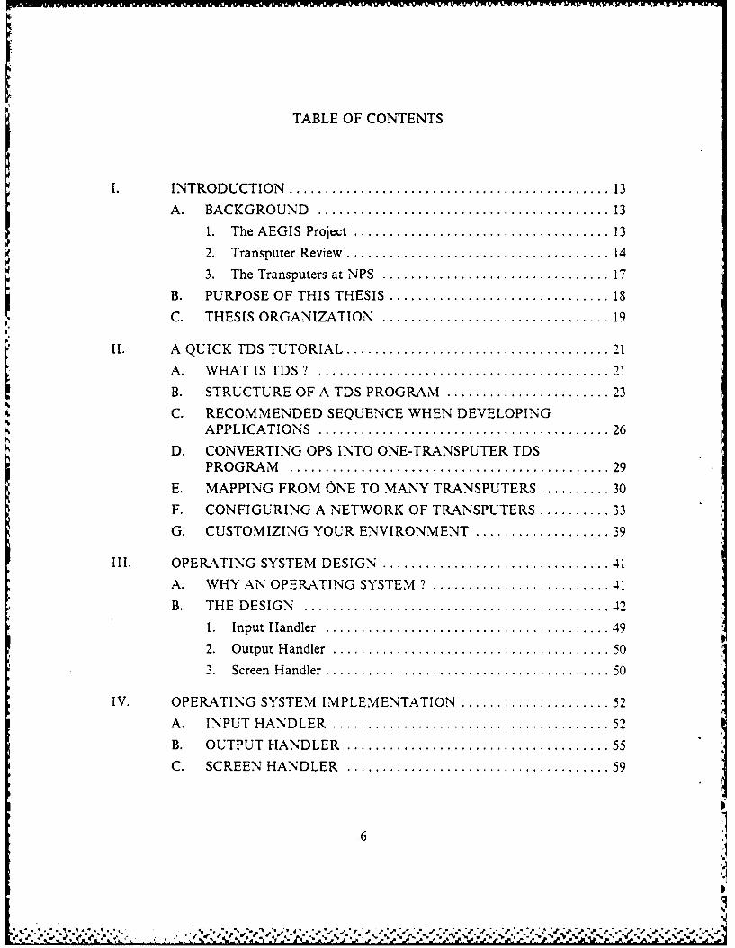
TABLE OF CONTENTS
INTRODUCTION.......................................... 13
A. BACKGROUND ...................................... 13
1. The AEGIS Project.................................. 13
2. Transputer Review .................................. 14
3. The Transputers at NPS.............................. 17
B. PURPOSE OF THIS THESIS............................. 18C. THESIS ORGANIZATION.............................. 19
I. A QUICK TDS TUTORIAL .................................. 21
A. WHAT IS TDS ?. . . . . . . . . . . . . . . . . . . . . . . . . . . . . . . . . . . . . . 21
B. STRUCTU RE OF A TDS PROGRAM ...................... 23
C. RECOMMENDED SEQUENCE WHEN DEVELOPINGAPPLICATIONS ...................................... 26
D. CONVERTING OPS INTO ONE-TRANSPUTER TDSPROGRAM .......................................... 29
E. MAPPING FROM ONE TO MANY TRANSPUTERS .......... 30
F. CONFIGURING A NETWORK OF TRANSPUTERS .......... 33
G. CUSTOMIZING YOUR ENVIRONMENT..................3J9
II. OPERATING SYSTEM DESIGN.............................. 41
A. WHY AN OPERATING SYSTEM ? ........................ 41
B. THE DESIGN ........................................ 42
1. Input Handler ..................................... 49
2. Output Handler .................................... 50
3. Screen Handler..................................... 5 0
IV. OPERATING SYSTEM IMPLEMENTATION .................... 52
A. INPUT HANDLER .................................... 52B. OUTPUT HANDLER .................................. 55C. SCREEN HANDLER .................................. 59
.6
I

D. THE ROUTING TABLE ................................... 60E. OPERATING SYSTEM LIBRARY ROUTINES .............. 62
1. The Send Routine ................................. 622. The Receive Routine .... ............................... 643. The Root Library (ROOTLIB.TDS) ...................... 654. The Remote Library (REMOTE_LIB.TDS) ................ 65
V. EVALUATION OF THE OPERATING SYSTEM .................. 67A. INTRODUCTION .................................... 67B. A BRIEF DESCRIPTION OF THE EVALUATION ............ 67C. EXPERIMENTAL RESULTS .............................. 71
1. Evaluating Direct Communications ....................... 712. Evaluating Multiple Path Communications ................. 72
D. EFFECT OF THE HEADER SIZE IN THE TRANSFERR A T E .................................................. 76
E. A CONTROVERSIAL PROBLEM ........................ 78
VI. USING THE OPERATING SYSTEM ............................. 81A. INTRODUCTION ........................................ 81B. THE REQUIRED PROGRAM STRUCTURE ................. 81C. PROGRAMMING WITH THE OPERATING SYSTEM ........ 83D. ADVANTAGES OF THE OPERATING SYSTEM ............. 84E. CUSTOMIZING THE OPERATING SYSTEM ................ 84
VII. CONCLUSIONS AND RECOMMENDATIONS ................... 85A . CON CLUSION S ......................................... 85B. RECOMMENDED FOLLOW-ON WORK .................... 86
APPENDIX A: OPS GLOBAL DEFINITIONS (GLOBALDEF.OPS) ........ 88
APPENDIX B: TDS GLOBAL DEFINITIONS (GLOBALDEF.TDS) ........ 90
APPENDIX C: TDS LIBRARY ROUTINES WITHOUT OPERATINGSYSTEM (LIBRARY.TDS) .............................. 91
APPENDIX D: THE OPERATING SYSTEM FOR THE ROOTTRANSPUTER (ROOTOS.TDS) ........................ 104
7
p , ' " "e . , . / . " " + + " ' " " " -" "," " " ° " " " " , . . . . . . . ° o , ,/
, ., , ..+ .+ ., ,; .. .,, ,. .. ... ... ., ., .. ., .., , , ,. . .. , .. , ., ,. , . ., , .. , ... : :. -. ,- .... :. :. .:. .: .. ..

7417IPWYOV In V vRv~T7-Tlr v-r i.,vwvwm %IV wvqw.,v ,,% Kr"ILIc VX-Wx.? NE 1 Z1I
APPENDIX E: THE OPERATING SYSTEM FOR REMOTETRANSPUTERS (REMOTE OS.TDS) ................... 127
APPENDIX F: THE EVALUATION PROGRAM FOR THE
OPERATING SYSTEM (EVALOS.TDS) ................ 143
LIST OF REFERENCES............................................ 158
BIBLIOGRAPHY ................................................ 159
INITIAL DISTRIBUTION LIST...................................... 160
8
'p0
'd"
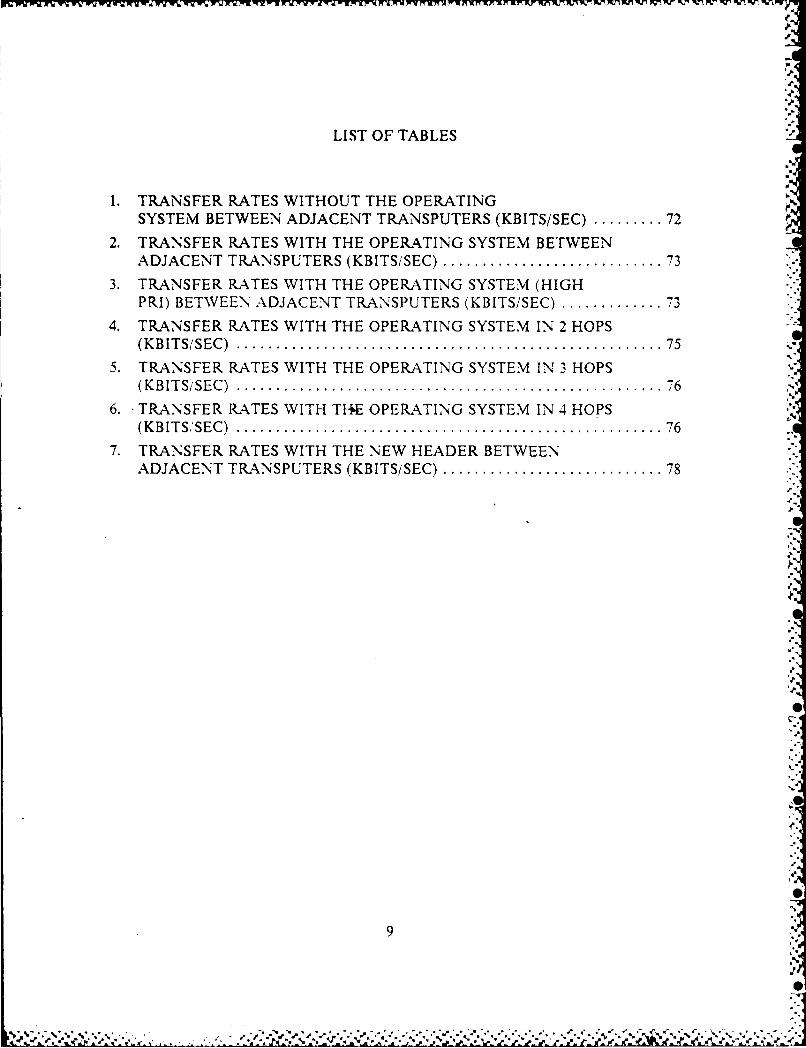
LIST OF TABLES
1. TRANSFER RATES WITHOUT THE OPERATINGSYSTEM BETWEEN ADJACENT TRANSPUTERS (KBITS/SEC) ......... 72
2. TRANSFER RATES WITH THE OPERATING SYSTEM BETWEENADJACENT TRANSPUTERS (KBITS/SEC) ............................ 73
3. TRANSFER RATES WITH THE OPERATING SYSTEM (HIGHPRI) BETWEEN ADJACENT TRANSPUTERS (KBITS/SEC) ............. 73
4. TRANSFER RATES WITH THE OPERATING SYSTEM IN 2 HOPS(K B IT S/SEC ) ...................................................... 75
5. TRANSFER RATES WITH THE OPERATING SYSTEM IN 3 HOPS(K B IT SiSE C ) ...................................................... 7 6
6. TRANSFER RATES WITH TI-W OPERATING SYSTEM IN 4 HOPS(K B IT S,;SE C ) ...................................................... 76
7. TRANSFER RATES WITH THE NEW HEADER BETWEENADJACENT TRANSPUTERS (KBITS/SEC) ............................ 78
9

17,
LIST OF FIGURES
1.1 T414 and O PS Tim ers ............................................. 15
1.2 T414 M em ory Space .............................................. 16
1.3 B003 board and its fixed connectivity ................................. 18
2.1 DEC VT-100 Keyboard Layout ................................. 212.2 Program Structure in TD S ......................................... 24
2.3 A Network with four Clusters ...................................... 282.4 O PS program .................................................... 31
2.5 C onverting to TD S ............................................... 32
2.6 The Previous Program Mapped onto many Transputers ................. 33
2.7 Steps 1, 2 and 3 of a Configuration .................................. 36
2.8 The Complete Configuration ....................................... 37
2.9 A Simplified Configuration ......................................... 382.10 File extensions ................................................... 40
2.11 Sample login.com for the VAX/VMS ................................. 40
3.1 The M essage Header Format ........................................ 433.2 The Possible Communications Paths ................................. 44
3.3 An OCCA M Limitation ........................................... 46
3.4 A Sample Channel-id Table ........................................ 47
3.5 U ser A bstraction ................................................. 48.6 Operating System Block Diagram .................................... 19
4.1 A General View of the Input Handler ................................ 524.2 Input Handler Source Code (Partial) ................................. 54
4.3 The O utput H andler ...................... ....................... 56-1.4 The Expected Behaviour
-1. T h Ex ect d B hav our ................... ........................ 57
4.5 The A ctual Behaviour ............................................. 574.6 The Parallel Solution .............................................. 58
4.7 Checking the Routing Table for Cycles ............................... 63
5.1 The Configuration used in the Evaluation Process ...................... 68
0
10
!I:.: ".""."""-" "" -'.

5.2 The Transfer Program in the Root Transputer (Partial) ................ 70
5.3 Transfer Rates with Direct Communications ........................... 74
5.4 Transfer Rates with Multiple Retransmissions ......................... 77
5.5 Effect of the Header Size in the Transfer Rate ....................... 79
6.1 The Program Structure when using the Operating System ................ 82
I
11,
I2

ACKNOWLEDGEMENTS
Dedico esta tese *aminha esposa Cristina e aos incus filhos Igor e Lucas, pelo
amor, compreensio e carinho dispensados durante toda esta dura jornada.
Aproveito a oportunidade, para expressar todo o meu amor e reconhecimento a
meus pais Franklin e Helena, sem os quais esta tese e eu proprio n~o existiriamos.
minha sogra Maria, o nieu especial e sincero muito obrigado, por todo o apoio
e carinho dispensados ai minha familia, por ocasi~o do nascimento de meus dois filhos.
To my thesis advisor, Professor Uno Kodres, I would like to thanks for all theconfidence and support, which has never stopped, even when hie was passing through
some health adversities.
Finally, I would like to send a special thanks to the Technical Staff in the
Computer Science Department, especially to Michael Williams, Walter Lanidakcr,
Russell Wallen and Rosalie Johnson, for all the support we were given throughout tis
thesis.
12
%" %

.11
I. INTRODUCTION
A. BACKGROUND'-
1. The AEGIS Project
The research interests of the NPS AEGIS project embraces a broad spectrum
of topical areas within the Computer Science Department. Initially found in the late
1970's it had the primary mission of investigating alternative architectures for the
AEGIS Combat System, which are being deployed on board of the U.S. Ticonderoga
class (CG-47), whose central unit is the 3D Phased Array Radar AN/SPY-lA.
The basic thrust of this research is the belief that the same software system
running under the old and expensives AN UYK-7 computers could run equally well. if
not more efficiently, in the commercially available VLSI microprocessors.
A sequence of projects have culminated in the successful Real Time Cluster
Star Architecture (RTC).
The RTC is a multiple microprocessor system with a hierarchical bus
structure resembling the Carnegie Mellon Cm architecture. RTC is specifically
suited for the development and implementation of real time, concurrent sensor data
gathering, display and control systems, which are some of the typical applications in a
Weapons System [Ref 11.
Presently, the RTC* is composed of two clusters, each containing four INTEL
Single Board Computers based on the 8086 microprocessor. These single boards have
from 64K up to 128Kbytes of dual port dynamic RAM being shared among each
cluster, with part of this memory space being virtually shared between clusters. All the
boards are connected to the INTEL Multibus through an interface control logic unit
and the communication between clusters is done via an ETHERNET link.
The software system to support the RTC was done in parallel with the
hardware design and after six years or iterative engineering, retinement and extensions.
it evolved to the E-MCORTEX operating system, which was integrated in 1984 as a
system software layer over the multiuser CPM 86 operating system [Ref. 2: p. 101.
As time progresses, the old AN/UYK-7"s in the AEGIS system are being
replaced by the new AN/UYK-43's, and as expected, in probably less than one decade
they will not be capable of handling the increasing demand for some more complex
software systems.13
13 -'p
Sq
- "....-... ..:.? " ..'..- ".-.-..,..-..'.--- .'- - - -- . " .. - .. -.- .. i. : --.,'. .: i.-." .. : .. o

That is why the NPS AEGIS Modeling Project, trying to keep up with all the
upcoming new technologies, has added to its Laboratory a network of eighteen
transputers, which can be very easily connected in various configurations, to allow the
user to evaluate and compare them, in a performance basis with the RTC
architecture.
2. Transputer Review
The term transputer is an acronym for "transistor computer' where it reflects
the ability of this device to be used as system's building block, much like the transistor
was in the past. The nice feature of the transputer is that it adds a new level of
abstraction, which provides a very simple way to design concurrent systems.
As a formal definition we could state that a transputer is a single chip
microcomputer with its local memory and with four independent links for connecting
one transputer to another. The links may be thought of as small special purpose
processors which steal no cycles from the main cpu, in such a way that we could have
all four links and the cpu working at the same time, without degrading the performanceof the program's execution [Ref. 31.
The interprocess communications are done through channels, using a strictly
message passage schema where shared memory is not allowed. Each link provides two
channels, one in each direction. A message is transmitted as a sequence of -bytes and
the way the transputers know when the other transputer is ready to receive a message
is as follows: the first transputer to become ready transmits the first byte of the
message and once it arrives in the other end, it is stored in the buffer of that link, and
just when that link is ready to receive the next byte an acknowledge signal is sent back.
Each of the links must maintain a buffer of one byte long for this purpose.
The communications between links is bytewise asynchronous and not phase
sensitive, but it is, obviously, bitwise synchronous, otherwise we could not sample the
bits correctly.
a. The processsor and its scheduler
The transputer, IMS T414. is a general purpose 32 bit microprocessor with
a maximum throughput of 10 MIPS.1 It is highly optimized to implement the OCCAM
Programming Language and it has a reduced instruction set, where many of the
instructions are one byte long.
1 It depends on the type of the transputer, more specifically on the internal clock
under which it is running. The following values apply: T414-12 (6 MIPS), T414-15 (7.5MIPS) and T414-20 (10 MIPS).
14
. . .
The processor supports two priority levels, high and low, and for each of
them it keeps a queue of ready processes. The low priority processes will run only when
there are no high priority processes in the queue.The OCCAM parallel construct is implemented on a single transputer, by
timeslicing the processes which are ready at any instant in time. A process is
descheduled if it has to wait for communications, timer input or if it completes
processing. Another possibility for descheduling, valid only for low priority processes iswhen its timeslice is finished, so that the next in the queue will be activated. Each
timeslice period lasts for approximately 800 microseconds.
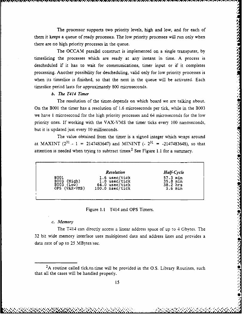
b. The T414 Timer
The resolution of the timer.depends on which board we are talking about.
On the B001 the timer has a resolution of 1.6 microseconds per tick, while in the B003we have 1 microsecond for the high priority processes and 64 microseconds for the low
priority ones. If working with the VAX-VMS the timer ticks every 100 nanoseconds,
but it is updated just every 10 milliseconds.The value obtained from the timer is a signed integer which wraps around
at MAXINT (231 - = 2147483647) and MININT (- 231 = -2147483648), so that
attention is needed when trying to subtract times. 2 See Figure 1.1 for a summary.
Resolution Half-CycleB001 1.6 usec/tick 57.3 minB003 (High) 1.0 usec/tick 35.8 minB003 (Low) 64.0 usec/tick 38.2 hrsOPS (VAX-VMS) 100.0 nsec/tick 3.6 min
Figure 1.1 T414 and OPS Timers.
c. lemory
The T414 can directly access a linear address space of up to 4 Gbytes. The
32 bit wide memory interface uses multiplexed data and address lines and provides a
data rate of up to 25 MBytes/sec.
2A routine called tick.to.time will be provided in the O.S. Library Routines, such
that all the cases will be handled properly.
15
: ." -. %" v ,- r . - . - . ' ". _ ."' .--- .N N '. - . -- " *' ' ~

There is 2Kbytes of on chip memory which provides a maximum data rate
of 80 Mbytes/sec and can be shared among different users through the internal system
bus. The latter value is obtained when using a memory with access time of 50
nanoseconds, but it also varies from transputer to transputer.
The address space of the T414 is signed and byte addressed. It ranges from
#80000000 which is equivalent to MININT, up to #7FFFFFFF which is MAXINT.
The first 2K of memory, in other words, from #80000000 up to #80000800 reference on
chip memory, where the first 72 bytes are reserved for system purposes. See Figure 1.2.
# "FrF Top or MEMIORY
#7F T FFF3 BOOTItAP FROM ROMl
0 00400 p PERIPERAL BASE AD It.
* 3000300 TOP ON CHIP MEMORY
9 60000048 MEM START
4 80000020 EVENT
4 6oooootC LIN1C3ifl
8 30000018 LINK2in
0 30000014 LINKlin SYSTEM MEMORY
*60000010 LINKOin
# 6000C LINK3..t
4 00000006 LI. 2..t* 80000004 LINKIo.t
* 80000000 LINKO-.t
Figure 1.2 T414 Memory Space.
16
.*%
- .%2w *. .. . . . . . . .
d. Links
The T414 has four full duplex standard links, each providing two
unidirectional channels. The links can be thought of, as described earlier, as a special
purpose processor which has some DMA block transfer capabilities.
The speeds of the links may be selectable from 10 Mbits/sec or 20Mbits/sec on the B003 boards, with no choice other than the standard 10 Mbits/sec on
the BOO board. The B003 board has the additional capability of maintaining link 0 at
10 Mbits/sec while the remaining links 1, 2 and 3 are at 20 Mbits. Therefore. -caremust be taken to enforce that both links connecting the BOO and the BOO3 board areworking at the same speed, 10 Mbits,,sec.
3. The Transputers at NPS
As far as hardware goes, we have in our Lab a Transputer Evaluation Modulewith four boards B003's. each containing four 32 bit transputers T414-15 (15 MHz)
plus 256Kbytes of dynamic RAM per transputer. The tifth board we have is the BOOIwith a 32 bit transputer T414-12 (12.5 MHz), 64K of dynamic RAM and 128Kbytes of
EPROM containing the bootstrap loader, the memory test and the transparent mode
software. This board is directly connected to the host computer (VAXiVMS in ourcase) through a RS-232 serial port and it also provides an additional port for attaching
one monitor.
We also have another board which is the B004, which is placed in one of theslots of a personal computer Zenith 248. This B004 board contains a 32 bit transputer
T414-15 (15 MHz) and comes with 2Mbytes of dynamic RAM on board. Its basic
function is to provide an interface between the PC and the network of transputers, butit also allows us to run programs in its transputer. much likely the BOOI. For additional
information about all the above mentioned boards, please refer to their respective
user's manual [Refs. 4,5,61.It is important to notice that the B003 board does not allow one to have
access to the links 2 and 3 of any of its transputers. They come in a fixed configuration
(see Figure 1.3), where the only links the user can connect however he desires are thelinks 0 and 1.
At present we have three software packages on which we can either simulate
or actually generate code for the transputer. They are:
* OCCAM Progamming System (OPS) which runs under the VAX'VMSOperating System and allows one to simulate the transputer environment, usingthe OCCAMI as the primary language. The code generated by the OPS
17
%

i . . .. . . .
B008
L LO L3 L
1L3
L 2
.s
L3 t Lem
comile iest thr therms VAX/MSrrehtly Anoe valid te meaSument ian theTransp gur le n Syste B003D00 board also runs fixer conetviy
cmieirrtVAX/VMSgse, sno thao validpie easurmnsu cnde
made, nor can we run truly multiprocessor programs. As it stands right now itis just a very good tool for teaching purposes, since it allows many uscrs to runand test their programs, concurrently. Another use of the OPS would be in theearly stages ofthe design, for checking the correctness of some modules, beforerunning them on the transputer itself
Transputer Development System (TDS-D600) which also runs Linder theVAX/VMS Operating System, and whose compiler generates transputer codewhich can be later on extracted and downloaded into a transputer network. Oneof its differences from the OPS is the configuration part, where a program canbe configured to run in various processors, which are connected in somespecified way. The primary language is still OCCAM I
*Transputer Development System (TDS-D701) which is very similar to the 13600,although more powerful, and it runs on an IMS B004 board in collaborationwith a small program running under the DOS Operating System in a personalcomputer, which provides access to the PC's resources. Its primary language isOCCAM2 which has data types, floating point arithmetic, among many otherthings that are not provided in OCCAM 1.
B. PURPOSE OF THIS THESIS
Since this is one of the First thesis to make use of the transputer hardware. 3 our
mission was to create a user friendly environment, with all the software necessary, (or
future users to develop their application programs.
3We had two previous thesis on transputers, but they were actually designed torun under the OPS in the VAX, since we had no transputers at the time they werewritten [Refs. 7,81.
18
t% %
The tools we are about to describe embraces a library with all the basic I/O
routines, such as output to the screen, input from the keyboard, capability of
formatting the screen and to write and read from VMS files among others. Also we
have developed some utility routines which will allow anyone to dump parts of memory
and to get the real time in a readable format anywhere in the program.
However, the central focus of this thesis is on the design and implementation of a
basic Communications Operating System, which would make it easier to program a
distributed network of transputers. All the effort was made to carry out this task and
after many, many changes, we ended up in a very simple and effective design. We are
not claiming that this is the only one or the best way of doing it, but it is our hope
that it serves as a firm foundation for future and more enhanced implementations.
We also evaluate what is the overhead imposed in the program's execution time,
when running under the Operating System, which constitutes one of the most
important concerns when dealing with real time systems.
Unfortunately, when this thesis was started we didn't have the OCCAM2 version
available to use as our primary language, which would have made life much easier. As
a result we are using PROTO OCCAM or OCCAMI throughout the entire thesis.
which is a very simple but primitive language, with no data types, no channel
protocols, no floating point arithmetic, etc....
As an auxiliary learning tool we will provide for the novice user of the
Transputer Development System for the VAXiVMS, a quick explanation of all its
features, its required program structure, its drawbacks and all the points we found
obscure in the manuals, whose knowledge would have saved us a lot of hours of
reading.
C. THESIS ORGANIZATION
Chapter II begins with a brief overview of the Transputer Development System.
in order to assist the reader in understanding its basic features. Next, we suggest a
sequence for developing applications, where we present a very thorough description of
all the steps involved. Still in this Chapter, we develop a very simple methodology forconfiguring a network of transputers. The remainder of Chapter II is devoted to some
general suggestions, in order to make the working environment, as friendly as possible.
Chapter III describes all major design decisions we had to make, in order to
implement the Operating System. The main purpose in doing that, is to provide the
19
a- * °-
reader with a precise conceptual understanding of the system, which would enable himto perform some major changes in the system, if it is so needed. It also presents a
general block diagram of the Operating System.
Chapter IV describes the implementation of the modules in the Operating
System. The Library Routines are also covered, mainly the "send" and "receive"
routines. A complete guide explaining how to use the routing table is also addressed.
Chapter V evaluates the performance of a program running under the operating
system. All the evaluation is done in a comparison basis with the one made by Vanni
J.F. in his thesis [Ref. 91, where the transputer is completely evaluated. In this Chapter,
we also perform the evaluation of the operating system, when handling multiple hop
communications. At the end of Chapter V, we measure the effect of the header size on
the transfer rates.
Chapter VI basically describes how to use the Operating System, under the user's
point of view. The required program structure is also presented, as well as some hints
in how to program with the operating system.
Chapter VII is the final chapter, which includes the conclusions and some
suggestions for follow-on work.
Appendices A and B includes the global definitions to be used in either OPS or
TDS.
Appendix C contains the file LIBRARY.TDS, with all the available routines to
be used in TDS, without using the operating system.
Appendix D contains the source code for the Operating System in the root
transputer, while Appendix E contains the remote version of it, in other words, the one
which is to be run in remote transputers.
Appendix F describes the evaluation program used to evaluate the Operating
System, and it also serves as a sample example on how to use the operating system.
2
20
I

II. A QUICK TDS TUTORIAL
A. WHAT IS TDS ?
The name TDS stands for "Transputer Development System" and it is basically
built around the concept of "folding".
Its fold editor is the principal interface between the system and the host
computer. It allows the user to insert, edit and delete Occam source text, and to save
this text into a VMS file.
Besides its general and standard editing functions, it also contains a set of ten
utilities and three special functions, which perform extended tasks with a TDS
program.
We will now cover the basics of its folding system, describing all the available
commands. We hope that by now the reader has already been exposed to the editor
tutorial, where all the basics about "folds" is covered. It is also important to notice at
this point, that this editor uses a very unusual sequence of keystrokes and therefbre it
is of primary importance to have the correct terminal driver running under it. We will
assume hereafter that the system we are using is the TDS for the VAX and that our
terminal is the VT-100 or VT-200 (in VT-100 mode), but if that is not the case, please
refer to the TDS Installation Manual [Ref. 10: Section 11.
n=c a .TMuStrrta CMx W..! .!FUNC 2, TLA14SPUTU COWILS
flm1C s. NkhZ P OCLAM {....WKSS 4, MALE SC PIODC
n=R s, IITIACT TO FILl
MI .1111150 STABA
MUIC s, SLAtC
"MN S, 19PLACU1 -iOYtrMc e* LIST . l I LF L
WK f, FOLD IwVo [I 1 12CILArTlo Sr FCOLD
Figure 2.1 DEC VT-100 Keyboard Layout.
21
% ' % , "%
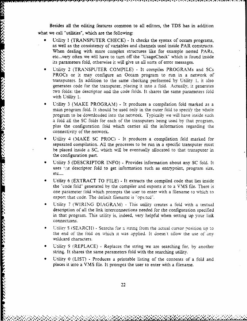
Besides all the editing features common to all editors, the TDS has in addition
what we call "utilities', which are the following:0 Utility I (TRANSPUTER CHECK) - It checks the syntax of occam programs,
as well as the consistency of variables and channels used inside PAR constructs.When dealing with more complex structures like for example nested PARs,etc...very often we will have to turn off the "UsageCheck" which is found insideits parameters fold, otherwise it will give us all sorts of error messages.
0 Utility 2 (TRANSPUTER COMPILE) - It compiles PROGRAMs and SCsPROCs or it may configure an Occam program to run in a network oftransputers. rn addition to the same checking performed by Utility 1, it alsogenerates code for the transputer, placing it into a fold. Actually, it generatestwo folds: the descriptor and the code folds. It shares the same parameters fold
or. with Utility 1.• Utility 3 (MAKE PROGRAM) - It produces a compilation fold marked as a
main program fold. It should be used only in the outer fold to specify the wholeprogram to be downloaded into the network. Typically we will have inside sucha fold all the SC folds for each of the transputers being used by that program.plus the configuration fold which carries all the information regarding theconnectivity of the network.
" Utility 4 (MAKE SC PROC) - It produces a compilation fold marked forseparated compilation. All the processes to be run in a specific transputer mustbe placed inside a SC, which will be eventually allocated to that transputer inthe configuration part.
- Utility 5 (DESCRIPTOR INFO) - Provides information about any SC fold. Ituses 1'e descriptor fold to get information such as entrypoint, program size,etc....
0 Utility 6 (EXTRACT TO FILE) - It extracts the compiled code that lies insidethe "code fold" generated by the compiler and exports it to a VMS file. There isone parameter Cold which prompts the user to enter with a filename to which toexport that code. The defl'ult filename is "ops.tcd".
a Utility 7 (WIRING DIAGRAM) - This utility creates a fold with a textualdescription of all the link interconnections needed for the configuration specifiedin that program. This utility is, indeed, very helpful when setting up your linkconnections.Utility 8 (SEARCH) - Searchs for a string from the actual cursor position u to
1, the end of the fbld on which it was applied. It doesn't allow the use of' anywildcard characters.
0 Utility 9 (REPLACE) - Replaces the string we are searching for, by anotherstring It shares the same parameters fold with the searching utility.
a Utility 0 (LIST) - Produces a printable listing of the contents of a fold andplaces it into a VMS file. It prompts the user to enter with a filename.
22
4.%
W- 0rr'79 -I r-4 -X -Fl:1 7 7% VP
Besides the above utilities we have three more special functions which are:
0 Func h (HELP) - Displays a list of all ten utilities provided by the TDS, with abrief description.
0 Func f(FOLD INFO) - Displays the type of the fold and its contents.
9 Func s (SETUP) - Allows the user to change any of the parameters fold alreadyinstantiated with new values.
Once we have gone through this brief description of what TDS is, we should nowhave the feeling that TDS is very closely related to its fold system. Unlikely othersystems where we have a physically separated editor, compiler and linker, in the TDSwe have all in one. Also another good point about this approach is that if you get an
error while compiling you will be placed right at the error in editing mode, and once
ready just call the right utility to compile it again !The way this editor handles external files is also very unique. What we have to
do is just to open a fold, name it with the filename and extension of the file we want tobe attached to this fold, press the file key PF3 and that is it. That is how it does the
job of linking almost transparent to the user.Just for the sake of completeness, it is worth mentioning the system files which
are used by the TDS:
* TDSVTI00.OBJ - Transputer Development System for VT-100 terminals.* TDSVI920.OBJ - Transputer Development System for the TVI-920 terminal.
* TDSTABLE.OBJ - Transputer Development System with table-driventerminals.
* OPSKRNL.OBJ - TDS Kernel which is identical to the OPS kernel.* TDSSETUP.COM - It is a VMS command file which sets up the TDS
environment. Must be executed in the beginning of every session.
B. STRUCTURE OF A TDS PROGRAMIn this Section we will cover the basic structure of a TDS program when running
without the Operating System, which will be covered in later Chapters. Any program
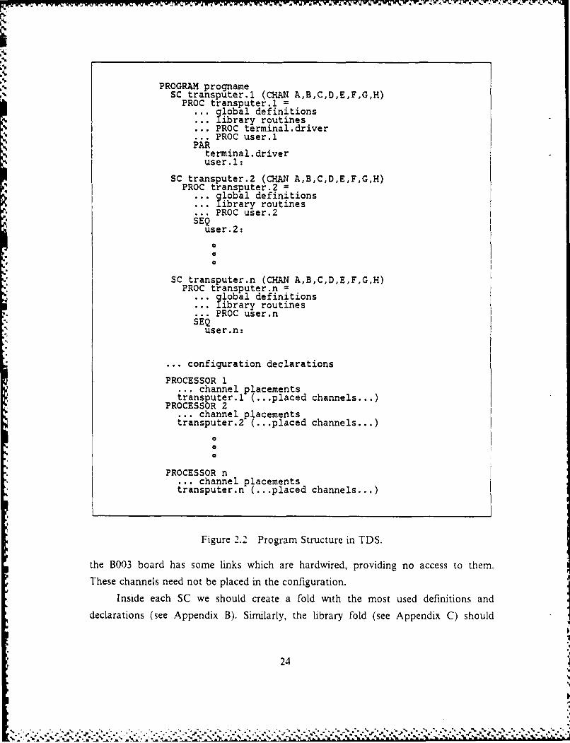
intended to run under TDS, in other words, in a transputer network, must have a welldefined structure, which doesn't allow much freedom for changes (see Figure 2.2).
The basic idea is that for each different process to be run in a differenttransputer, we must make it a separately compiled unit. The number of parametersdepends on how many hardware links are being used by that process, and also if anyconstants are coming as parameters from the configuration part. As we already know,
23
PROGRAM prognameSC transputer.l (CHAN A,B,C,D,E,F,G,H)
PROC transputer.1 =
... lobal definitions. library routines.. PROC terminal.driver... PROC user.1PAR
terminal, driveruser.1:
SC transputer.2 (CHAN A,B,C,D,E,F,G,H)PROC transputer.2 =
.lobal definitionslibrary routinesPROC user.2* SEQ
user.2:
SC transputer.n (CHAN A,B,C,D,E,F,G,H)PROC transputer.n =
.. lobal definitionsibrary routines... PROC user.n
SEQuser.n:
... configuration declarations
PROCESSOR 1... channel placementstransputer.1 (...placed channels...)PROCESSOR 2... channel placementstransputer.2 (...placed channels...)
0o0
PROCESSOR n... channel placementstransputer.n (...placed channels...)
Figure 2.2 Program Structure in TDS.
the B003 board has some links which are hardwired, providing no access to them.
These channels need not be placed in the configuration.
Inside each SC we should create a fold with the most used definitions and
declarations (see Appendix B). Similarly, the library fold (see Appendix C) should
24

contain some often needed routines such as I/O routines and other utilities. Our
suggestion is that all useful routines should be included in this fold, as they are created.
The approach we have taken is to make them filed folds in such a way that whenever
you make a new program, all you have to do is create two new folds and attach those
files to them.
The sequence of steps to attach these files in our program is the following:
1. Make sure you have these files in your working directory.
2. Open a fold inside the program you are working on.
3. Name this fold with the name of the file you want to attach.
.4. File this fold by pressing PF3 on the VT-100 terminal.
5. If you have some limitation in memory or if you are not going to use all theroutines and definitions that are in there, you should unfile those folds in orderto not interfere with the original contents and proceed with the desiredmodifications. This step as we can see is an optional step and is just carried outfor memory savings and readability purposes.
As depicted in Figure 2.2, the third fold inside the SC PROC is the terminal
driver, which is crucial if we are using screen outputs or keyboard inputs. It defines
hardware memory locations which represent uart (universal asynchronous receiver-
transmitter) registers, such as mode register, status regis. . command register, etc....
All of these are defined as offsets to the peripheral base addess which is #80040000.
Its basic functions are to reset the uart which we are going to work with, 4 and to
define the baud rate for communications between the processor and the monitor. The
first one is accomplished by the procedure reset.uart and since it takes a while for the
uart to become ready, a built-rn delay is provided inside this procedure.
The terminal driver is always ready either to receive a character typed at the
keyboard or send something to the screen. If you check the code it is clear that both
tasks are just performed after the uart receives a tx.ready or a rx.ready in the status
register. Furthermore, if the uart does not receive either flag within 5.12 seconds, the
uart is considered to have failed and the terminal driver is exited without further notice!
The reason I am teiling you this is because we had some intermittent problems in ,he
very beginning of our research, which were very nasty to isolate, and ended up being a
problem in the uart.
4 We have two uarts, the uart A is connected to the terminal and uart B to the
host computer.
25

J - - -- ,I
It is also worth mentioning that unlike OPS, where we must send the "end of
* buffer" ascii code at the end of the message we are going to output to the screen, in
*' TDS we don't have to.
The terminal driver must be placed in PAR or PRI PAR with the user process in
order to work properly. The choice of either one construct is not always clear, and it is
* intimately related with performance, but the unwary use of it may bring up subtle
points when dealing with complex programs with nested PARs and PRI PARs, so that
the suggested approach is to make your entire program with no PRI constructs and
* just after it has been proved correct, you should assign the priorities where needed.
In the PROC so called "user.n', we have a standard structure like any' other
* programming language such as Pascal, PL,'I, etc... where we have a declarations part. a
bunch of procedures which may be nested at any level and finally the main body of our
outer PROC user.n. The only main difference is that we should make the channel
. placements inside this procedure, attaching the software channels to the hardware '.Inks
of the particular transputer, to which that process is going to be downloadea. Of
course, these placements must be in accordance with the configuration.
As one may notice we have put A, B, C, D, E, F, G and H as channel
parameters for the SCs, but rather than calling them generically as we did, we could
- just as well have put the actual channel's names' as parameters. In doing so, we
wouldn't have to make their placements inside the PROC user.n, since they were going
to be directly related to the order specified in the configuration.
C. RECOMMENDED SEQUENCE WHEN DEVELOPING APPLICATIONS
In this Section we will present a suggested sequence of steps when building
applications, which in our understanding provides the best results mainly when deaiing
with medium to large programs. During this and the next few Sections we will be
dealing with the same basic program in order to give you a better global idea of all the
steps involved.
For the time being assume that the requirements definition and the functional
specification phases are compieted and the architectural design is undervav with all ,ihe
modules and interfaces already defined.
At this point since all the main modules with their interfaces are already
specified, we can have a good idea of how many processors could we use to map our
application, as well as which modules could be placed in different processors.
26
.i
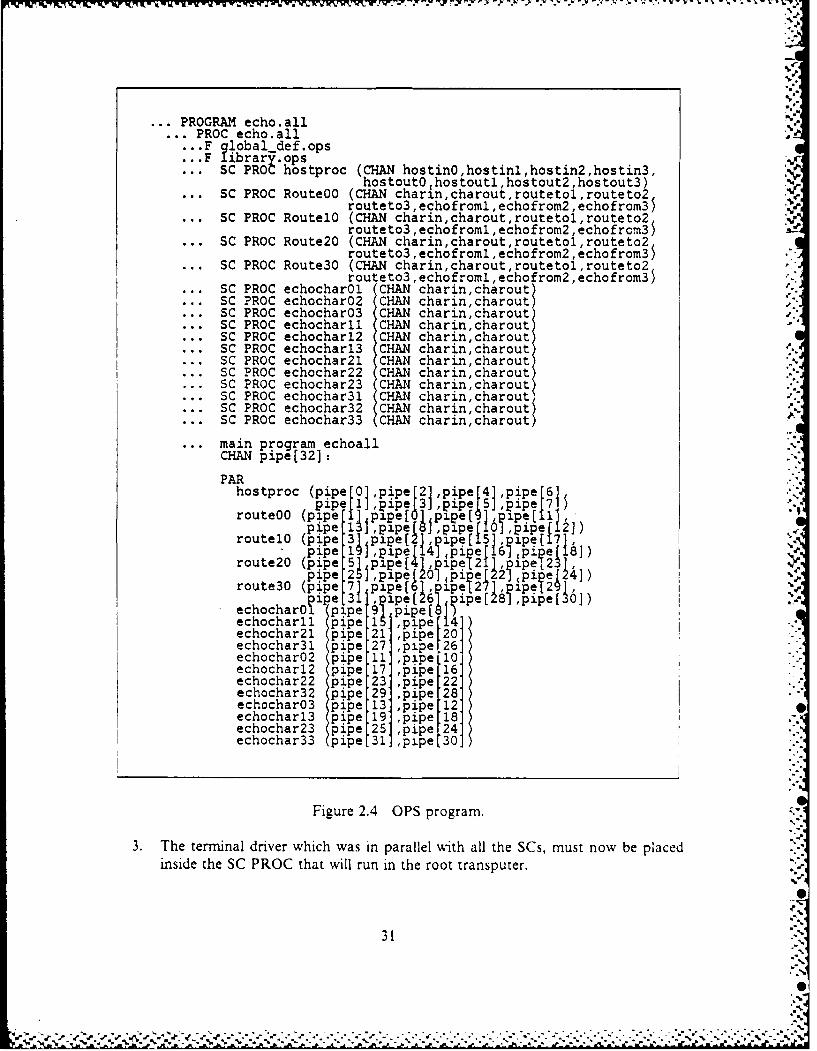
The experimental network will be as depicted in Figure 2.3 where we have 17 ,%
transputers divided into 4 clusters with 4 transputers each, and one root transputer.
The main purpose of this program will be to allow the novice OCCAM programmer to
understand the structure of a TDS program, as well as how to configure a network of 1'
transputers.
In this program the root transputer will be running the so called "hostproc",
which basically receives a character typed on the keyboard and broadcasts it to four
transputers, one in each cluster. Upon receiving the character, these transputers which
will be running the process "route", will route the character to each of the transputers
left in that cluster. Finally, all the recipient transputers will echo back the same
character to the root transputer, so that at the end of the program we will have 12
characters printed on the screen.
The next phase in the traditional software engineering life cycle is the module
design, where all the interfaces between modules should be already defined. The module
design is concerned with internal features of the module like algorithms, data
structures, etc.... In OCCAM terms, the main goal of the module design should be to
implement each module as an SC PROC, where all the communication between
modules must be done via channels.
Once we are ready to start developing our modules, we can either use the OPS or
the TDS. This choice is not very clear, but seems to us that the OPS provides a nice
timesharing environment for the early stages of the design, since we could have many
users developing and testing their programs concurrently, under the VAXiVMS
operating system.
Once all the module design teams have their programs logically correct and
running under OPS, they should be integrated as dictated by the previous architectural
design, but still under the OPS, where all the interfaces between modules could be
checked and validated against typical inputs. As one can see up to this point, no
transputer hardware was necessary, and the reason we are emphasizing this is because
if we had chosen the TDS instead, we would certainly have had a bottleneck problem
in the usage of the B001 board, since it allows just one user at a time. Another main
reason in using OPS lies in the fact that in doing so, we could use the powerful S
debugging tools running under the VMS operating system.
The next step is a controversial one, where we transform an OPS program into a
one-transputer TDS program; it will be entirely covered in the next Section. Although
27
VV
XL.

L' WVVL- ILI U..- VVIi W~ "IL TV WVY YVWY WVYW 1r.v."'rJV's.% .'V *- ' ? I r-.- -'r ~
I0I1
d0
J
0 0
Figure 2.3 A Network with four Clusters.
28
" ".2"3
it looks like a redundant step, I can assure to you that it is not; many bugs can be
inserted into the program just by changing global definitions, changing library routines,
inserting the now required terminal driver and mainly when trying to use the unique
TDS constructs such as BYTE.SLICE.INPUT, WORD.SLICE.OUTPUT, etc... instead
of the standard OCCAM channels i,,o operations, which are much less efficient (2 to 5
times) than the previous built-in procedures, as fully documented in the Reference 9.
Of course this last change need not be done if you don't have any sort of time
constraints, otherwise they are crucial, since the differences in time are enormous.
If for anything else, this step should be carried out in OPS, just because we have
much better debugging capability than when running in many processors, and keep in
mind that any multiprocessor program adds some new potential sources of errors,
which are not always easily identified!
Finally we should map this one-transputer program onto a n-transputer program.
where this "n" is dictated by the number of modules (SC PROCs) we have. which can
be parallelized, and of course by the availability of processors. This conversion process
will be described in Section E.
As one can realize, this methodology will not help as far as real time debugging
goes, but it will at least provide an effective way to achieve static logical correctness of'
the program.
D. CONVERTING OPS INTO ONE-TRANSPUTER TDS PROGRAM
According to our recommended sequence for developing applications, there will a
point in time when you have developed your program under OPS and want to run it in
a single transputer. In these cases you should proceed by checking all the globai
definitions to see if they are still applicable to a TDS program. lor cxample. the
channel Screen in OPS must be placed at "'1" and the channel Keyboard at 2", but in
TDS this cannot be done, since "1" and "2" will correspond respectively to linklout and
link2out addresses. Actually, in TDS the Screen and Keyboard are standard channels
which communicate with the termnal driver routine and thev don t need to be olaced.
Those are the basic differences between the global definitions for OPS and for TDS,
but for further comparison refer to Appendices A and B, where we present both files. It
is important to notice that these globaldef.ops, global_def.tds, library.ops and the
library.tds files are not required by OCCAM, they constitute just another way of
structuring a program, and making it easier to read and maintain.
29
e.1
Now if we look at Figures 2.4 and 2.5 we can see very easily all the steps
involved in converting the OPS program.5 First, as already suggested in the previous
paragraph, we should change all the global definitions, as well as the library routines
by the TDS equivalents. Second, you should include the terminal driver routine, which
is used just in TDS. and place it in parallel with the main user process which was
running under OPS. Third, change the PROGRLAM fold which is embracing the whole
OPS program by an SC fold, otherwise we won't be able to instantiate it in the
configuration part.
Finally, you have to do the configuration part, and since we are talking about a
program to be run in just one transputer, the configuration becomes extremely simpie,
where we have only the Processor number, followed by the name of the outermost SC
PROC, with no channel parameters, since no external communication is going to take
place. As you may have noticed, we inserted an additional fold of type PROGRAM
embracing the SC and the configuration. This is not necessary, it oniy ailows to
compile and configure at the same time, otherwise you will have to apply the 'compile
utility" in both folds separately.
Once your program is successfully compiled in TDS and it is running properly,
you could then try one more refinement step in order to speed up your program, and
tlat is by using the unique TDS constructs like BYTE.SLICE.INPUT,
WORD.SLICE.OUTPUT, etc ... instead of the standard OCCAM channels io
operations like "chan ?" and "chan !". When you are done, compile and run it again.
E. MAPPING FROM ONE TO MANY TRANSPUTERS
Although we recommend to perform the previous step in every program. we
understand that the experienced programmer may skip that step for small or even
medium programs, but when dealing with more complex programs with intensive
communications between processes, it is strongly advised to run it first in one
transputer, where you have more debugging capabilities and once it is proven to be
'ogicallv correct and with no deadlocks, we should map it onto more transputers.
The boasic steps zo accomplish this mapping are the fbilowing:
1. Remove the outermost SC PROC.
2. Find those SC PROCs which have exactly the same code, differing just by thename and merge them into just one SC PROC with a common name.
5For convenience we have marked with an asterisk all the changed lines in the
converted TDS program presented in Figure 2.5.
30
PROGRAM echo.all..PROC echo.all
.. F global-def.ops...F library.ops
..SC PRO C hostproc (CHAN hostinO,hostinl,hostin2,hostin3,hostoutO I hostou t1,hostout2,hostout3)
..SC PROC RouteOO (CHAN charin,charout,routetol,routeto2routeto3 ,echofrom , echofrom2 ,echof rom3 5
..SC PROC RoutelO (CHAN charin charout,routetol,routeto2route to3 ,echo fromi ,echofrom2 ,echofron3
..SC PROC Route:2O (CHAN charin,charout,routetol,routeto2routeto3 ,echofroml ,echofrom2 ,echofrom3
..SC PROC Route:3O (CHAN charin~charout,routetol routeto2route to3 ,echofromi ,echo from2 ,echo from3 5
..SC PROC echochar~l CA hrncaotSCRC chchro2 (C= charin,charout
... SC PROC echochar3 CA charin,charout..SC PROC echochari (CHA charin,charout?
... SC PROC echocharl CHAN charm charoutSC PROC echocha rl3 2CHA charincharoutSC PROC echochar13 CHAN charin,cha rout -
..SC PROC echochar2 CHA charin,charout
..SC PROC echochar23 CHAN charin,charoutSC PROC echochar3l CHAN charin,charoutSC PROC echochar32 CHAN charin,charoutSC PROC echochar33 ICHAN charin,charout
... main program echoallCHAN pipe[32]:
PARhostproc (pipe 0 pp pp 4 pp 6
pp 1,pipe[3 2pipe[5] ,pipellpip. 3I,pipe [],pipe 510 pipe 1)
routelO (p~p ~ 2ief L IA.JC ,ipe[ Ij
route10 (~p~ 31 ppe( 1P2 ~ ie 7pipe 1 I,pipe4 Aylpiye[l2j ~piyel 4])
route20 (pipe 5j pipe( J,pipe 2 J,pipe [29
echch p1~pe 2~ pp ejiye 21 ,pipe[ 30])re3cr0 (ppe 21 ,pipe 20
echo31arPe pipe 27 ,pipe 26echochar021 Pipe 1 ppe [10echocharil pipe 17' 1pie 16echochar22 pipe 23* ,ipe 22'echochar32 pipe 29 ppe 28"echochar03 pipe 13 pipe 1echocharl3 pipe 19 ,pipe 18
echochar23 pipe 25 ,pipe 24echochar33 pip 31 ipe,30.
Figure 2.4 OPS program.
3. The terminal driver which was in parallel with all the SCs, must now be placedinside the SC PROC that will1 run in the root transputer.
31
..PROGRAM echo.all.. SC PROC echo.al.
* F ylobaldef.tds::.F library .tds
..SC PROC hostproc (CHAN hostin0,hostinl,hostin2,hostin3,hostoutO ,hostout , hostout2 ,hostout3)
..SC PROC RouteOO (CHAN charin,charout,routetol~routeto2routeto3 ,echofromi ,echofrom2 ,echofrom3 5
..SC PROC Route1O (CHAN charin,charout,routetol,routeto2route to3 ,echo from , echofrom2 ,echofrom3 5
..SC PROC Route2O (CHAN charin,charout,routetol,routeto2route to3 ,echo from , echofrom2 ,echo frorn3
..SC PROC Route30 (CHAN charin,charout~routetol,routeto2routeto3 ,echofromi ,echofrom2 ,echofrom3 S
... SC PROC echocharol (CHAN charin,chruSC POC ehocar02 CHAN cai hru
SC PROC echocha0 CHN charin,charout)SC PROC echochar?? (CMA charin,charout
..SC PROC echochrl CHA charin,cha rout
..SC PROC echocharl3 (CHAN charin,charoutSC PROC echochr? (CHA charin,cha routSC PROC echochar2 CHAN charin,charoutSC PROC echochar3 CA charin,cha rout
..SC PROC echochar2l (CHAN charin 'charout
..SC PROC echochar32 ICHAN charincharout
.. SC PROC echochar33 CHAN charin,charout... main program echoal
CHAN pipe[32]:PAR
* terminal.driver (Keyboard,Screen port,baud)hostproc (pipe Oj ,pipe 2 ,pipe [4 ,pipe 6
1i J,pe pipe 5 iprouteOO (pipe: ip'-% pipe[ yip,
pipe.5 Wpipei 20,pipej [22]pipe (21)route3O (pipe 3; pipe[6( p ipe[ 517,ipe[ 29
pipel I pipej6 4 ipe 28],pipe[3]re2char 1pipe ij 971l pi2 81)2echochapipepipep15e p2peI14
rechr (ppe 21 pipe 20 pyeechocharJl pipe 27 ,pipe 2
echochar02 pipe 11ppipe610echochar2 p1pe 17 pie[1echochar22 pipe 231 pie 2echochar2 pipe 29' pipe 28'echocharO2 pipe 13 ,pipe 12'
echocharl3 pipe 19 ,pipe 18'
echochar23 Pipe 25 ' pipe 24'*ec hochar33 Pipe 31 ,pipe 30'
* ... rafi tio* PROCES R 0
* echo.all
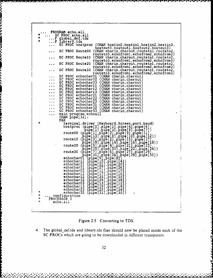
Figure 2.5 Converting to TDS.
4. The global def.tds and library.tds files should now be placed inside each of the
SC PROCs which are going to be downloaded in different transputers.
32
"e, "r
.11
5. Change the configuration to run the program in multiple transputers. This stepwill be covered in full detail in the next Section, so that for the time being wewill limit ourselves to write down the header of the fold.
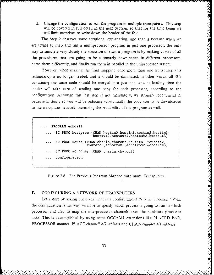
The Step 2 deserves some additional explanation, and that is because when we
are trying to map and run a multiprocessor program in just one processor, the only
way to simulate very closely the structure of such a program is by making copies of all
the procedures that are going to be ultimately downloaded in different processors,
name them differently, and finally run them in parallel in the uniprocessor system.
However. when making the final mapping onto more than one transputer, this
redundancv is no longer needed, and it should be eliminated, in other words, all SCs
containing the same code should be merged into just one, and at loading time the
loader will take care of sending one copy for each processor, according to the
configuration. Although this last step is not mandatory, we strongly recommend .t.
because in doing so you will be reducing substantially the code size to be downloaded
to the transputer network, increasing the readability of the program as well.
... PROGRAM echoall
SC PROC hostproc (CHAN hostinO,hostinl,hostin2,hostin3,hostoutO,hostoutl,hostout2,hostout3)
SC PROC Route (CHAN charin,charout,routetol,routeto2,routeto3, echofroml, echofrom2, echofrom3)
... SC PROC echochar (CHAN charin,charout)
... configurationp
Figure 2.6 The Previous Program Mapped onto many Transputers.
F. CONFIGURING A NETWORK OF TRANSPUTERS
Lets start y asking ourselves what is a configuration? Why is :t necded .'eil.
the configuration is the way we have to specify which process is going to run in which
processor and also to map the interprocessor channels onto the hardware processor
links. This is accomplished by using some OCCAMI extensions like PLACED PAR.
PROCESSOR number, PLACE channell AT address and CHAN channel AT address.
33,,,,
".5
• " " "1 ' .' . . " .' ' " .°
°" '.° " " ° " " . " " " ." " • . ." ." " ° 1 ". " - ."° • °j . " . •- " • . ." i " . -. -. . - 0.
The code for any processor must be contained in a single SC PROC and theprocessor number can be any valid integer, which is just a logical identifier of that
processor. However, the first processor to be declared must be always the root
transputer, in other words, the processor connected to the host computer, which is the
one responsible for bootstrapping and loading the code in the entire network.
-," Each of the SC PROCs may be instantiated on any number of processors in the
network, although it is exported from the host to the root just once. Further copies will
be provided and sent by the root transputer to the others in the network.
We have two ways of attaching software channels to hardware links, one is at the
program level and uses the CHAN AT statement, and the second is with the PLACE
AT statement which is used at the configuration level. The first one is optional, but if
we don't use it we must declare the channels explicitly as formal parameters to the SC,
and they will be mapped to the actual parameters, at the time that SC 's called or
instantiated at the configuration 'evei. On the other hand, if we decide to use the
CHAN AT statement inside our program. the parameters to the SC PROC can be i
any order and can have any name; the only thing that will be checked by the compiler
is the match of the number of formal against the number of actual parameters. If you
look back in our Figure 2.2 you will notice that we have used channels A. B, C. D. E.
F, G and H as formal parameters, what suggest to us that we have to ase some CHAN
AT statements inside our process "user.n".
If there is a requirement to connect two links from the same processor, a soft
channel must be used.
A network configuration can be viewed as a PROGRAM consisting of acoilection of SC PROCs which are instantiated from inside some PLACED P..\R
construct. SCs at this level must have just CIAN or VALLE types as lormal
parameters.
Let's go now through the configuration of our old program echo.all where all
these steps will be made much clearer for you. Usually. after deciding how many
parallel processes -ou are ,oing to have and vow many nrocessors ,ou are goinr lo
need, the next step is to detine how they will be connected in a very broad sense. So,
let's suppose we want to run the echo.all program in the network presented in the
Figure 2.3.
Once the previous base steps have been accomplished, we suggest the following
sequence of steps in order to properly configure a network of transputers:
I. Number all the transputers using a structured ordering schema (see Figure 2.7).
34
V .
2. Name the channels of the links used 6 to connect the different transputers. Wesuggest the use of an array of channels because it will allow you to make use ofreplicators as we will see later (see Figure 2.7).
3. Place the correct process in each of the transputers in the network (see Figure2.7).
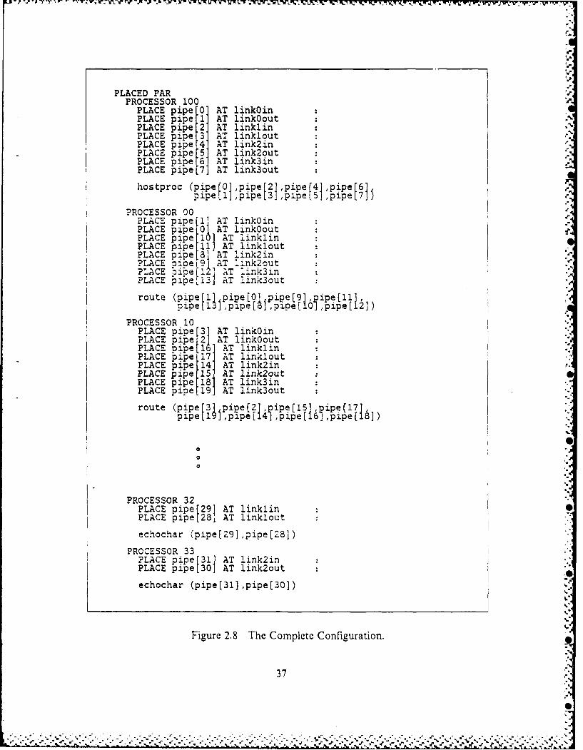
4. Start making the placements for all the transputers in the network, just byreading directly from your sketch (see Figure 2.8).
5. Instantiate the procedures such that the number of actual parameters matchesexactly the number of formal parameters in the SC PROC. The order isirrelevant if we are also making the link placements inside the SC PROC.
As demonstrated, the configuration is a very simple matter if we follow the
suggested steps, but sometimes when we have more than one processor executing the
same process, it is very likely that we will be able to recognize some fixed pattern in
their connectivity, which will allow us to simplify the configuration by using some
PLACED PAR replicators. That is why in the first and second steps we have suggested
to use a structured ordering schema for the transputer number and an array of
channels for the channel names. Now it is just a matter of finding a fixed pattern
between the channel index, transputer number and its link number. Finally, after some
reasoning, we were able to find an equivalent configuration which is showed in Figure
2.9. A further simplification could be to take out the placements of those hardwired
links in the B003 board, but this will be left as exercise for the reader.
This extra step is more an adornment than anything else, but it is strongly
recommended when dealing with very large networks, because in doing so we will
provide a better picture of our entire network. An experienced OCCAM prograrnmer
just by looking at the configuration, can have a pretty good idea of the connectivity of
the entire network, in other words, if it uses a tree structure, a pipeline, a ring, etc....
This feeling will be almost impossible if the processors are declared one at the time.
Two facts are important in this analysis, the first is to realize that no
simplification would be possible if there were no processors running the same process
and the second is to understand that this embellishment in the configuration is not
mandatory.
One of the points that we have just stated but didn't cover in detail was thedivision of a program in a parallel number of processes. It is obvious that not every
problem can be partitioned into smaller tasks to be carried out by different processors,
6The channels from the hardwired links in the B003 board, do not need to beplaced in the configuration part.
35
p
0-
• . " ". € . . ,. . qo o °o' o % .. • .o o . . o. " ° % -. * - ' o " ° . . . . . °. * ' • • . -

7 CCHOCRAR
Figure 2 Se1, 2ad3o oniuain
[23] 22] 2 (236
20 23
U- ~ ~ ~ ~ ~ ~ ~ ~ ~ ~ 2 *. S -CH ... .. .. .. . . .. . ... L A
l-
Uw-
PLACED PARPROCESSOR 100
PLACE pipeO AT linkOinPLACE pipe 1 AT link0outPLACE pi e'2' AT linklinPLACE pipe.3' AT linklout
PLACE pipe 4 AT link2inPLACE pipe 5 AT link2outPLACE pipe 6 AT link3inPLACE pipe 7 AT link3out
hostproc (pipe [0] ,pipe [2] ,pipef4] ,pipe [6]pipel] ,pipet3 ,pipeL5] ,pipe[7]5
PROCESSOR 00?LACE pipe I AT linkOinPLACE pipe 0 AT link0outPLACE pipe 11 AT linklinPLACE pipe 1 AT linkloutPLACE nioe 81 AT link2inPLACE kipe 9] AT link2out U-PLACE o~pe 2' T link3inPLACE kipe,13] AT link3out
route (pipe[l],pipe[O]pipe[9],ie[l].pipe[1 1 ,p e [8] ,pipe [0]pipe [12] )
PROCESSOR 10PLACE pipe 3] AT link0inPLACE pipe 2] AT link0outPLACE pipe' 16 AT linklinPLACE pipe[17] AT linkloutPLACE pipe.14] AT link2inPLACE pipe 15. AT link2outPLACE pipe[18] AT link3inPLACE pipe[19] AT link3out
route (pipe[31 pipe[2], ipe[151,3ipe17,pipe[19 1,pipe[ [ ]pipe( [ ]pipe [18]).[
PROCESSOR 32PLACE pipe [29] AT linklin 0PLACE pipe[28 AT linklout
echochar (pipe[29],pipe[28])
PROCESSOR 33PLACE pipe 31] AT link2inPLACE pipe[30] AT link2out
echochar (pipe[31],pipe[30])
Figure 2.8 The Complete Configuration.
37

W, -W W ' -V 4.4R
PLACED PARPROCESSOR 100
PLACE pipe"O AT link~inPLACE pip AT link~outPLACE pipe.2 AT linklinPLACE pipe 3' AT linkloutPLACE pipe 4' AT link2inPLACE pipe 5: AT link2outPLACE pipe 6 AT link3inPLACE pipe .7 AT link3out
hostproc (pipe [0 pipe[2],pipe [4] pipe[I],~
PLACED PAR j = [0 FOR 4]PROCESSOR 1O0
PLACE oipe 2*+1 T link~inPLACE kipe2*i 1AT Jlink~outPLACE pipe 10+ (6*j)] AT linklinPLACE pipe 11+ 6'*) AT linkloutPLACE Dipe 8+( 6*j AT link2inPLACE bipe 9+( *4' AT link2outPLACE oipe 12+(6w i AT ljnk3inPLACE pipe 13+(6* J) AT 4Link3out
route (pipe [(2* )+1. pipe[2* ] ,pipe +Gpipe 11+ 6'* f ,pape[ 1. ~ippe epipe 10+ 6*] 1,pipe[12+
PLACED PAR i = 10 FOR 4]PROCESSOR (10wi)+1PLACE pipe 9+ (6'-i) AT link3inPLAC pieL8+R(*i)] AT link3out
echochar (pipe[9+(6*i)],pipe[8+(6*i)])
PLACED PAR i =rOj FOR 4]PROCESSOR (10 1)+2PLACE pipe 11+ (6*i) AT linklinPLACE pipe 10+ ( 6li AT linklout
echochar (pipe[11+(6*i)] ,pipe[10+(6*i)])
PLACED PAR i [0FR4PROCESSOR 10 i4)+3PLACE7 oine 13+('6* i) AT link2inPLACE kie 12+(6*i) AT link~lout
echochar (pipe[13+(6*i)] ,pipe[12+(6*i)])
Figure 2.9 A\ Simplified Configuration.
but even if they could, at the --ctual state of the art, there is no automatic machine
where we put the entire program as input and the machine would generate an optimal
division of processes to be parallelied.
38
As a conclusion we should mention that this whole configuration procedure is avery simple one, even for very large and complex systems, and furthermore, the
program can be developed with little or no thought to such matters and then, therequired configuration can be performed after the program logic is proven to becorrect. It is in this way that large and complex programs can be written while the
actual hardware is still in paper design.Therefore, the key idea is that configuration does not affect the logical behavior
of a program. It only enables a program to be arranged so that its performance
requirements are met.
G. CUSTOMIZING YOUR ENVIRONMENTWhen dealing with either OPS or TDS, it is extremely important to create a
friendly environment to work, otherwise you will spend most of your time performing
unnecessary bookkeeping. The main reason for that is because a very big number of
files is created for each complete cycle of a program, 7 and since the default filenamesfor some of the above operations are pretty vague, it is important to define a more
strict file naming rule. Some other areas are also affected by the lack of a consistentnaming rule, for example, OPS and TDS programs are quite different but both use the
OCCAM programming language, so that if we use the traditional file naming rules, wewould end up with some name followed by the extension OCC for both programs,
which is not recommended by obvious reasons.For all these reasons we have decided to make up our own file naming rules,
which are described in Figure 2.10.
When you apply the utility to get a printout of an OPS or TDS program, all the
folds are opened and they come up as "--", which is exactly identical to a comment in
OCCAMI, so that to avoid confusion we will always use comments with "---" instead
of"--". This way, by looking at the printout, we will be able to very easily differentiate
a fold from a comment.
Another decision we had to make was regarding the global definitions and thelibrary routines each program was using. It was really messy to make a program,because we had to pick up routines and definitions from different places, and finallyput them inside our program, so that we decided to concentrate all in four files socalled global_deftds, globaldef.ops, library.tds and library.ops.
7For a cycle we mean the phases of editing, compiling, linking, extracting andprinting.
39
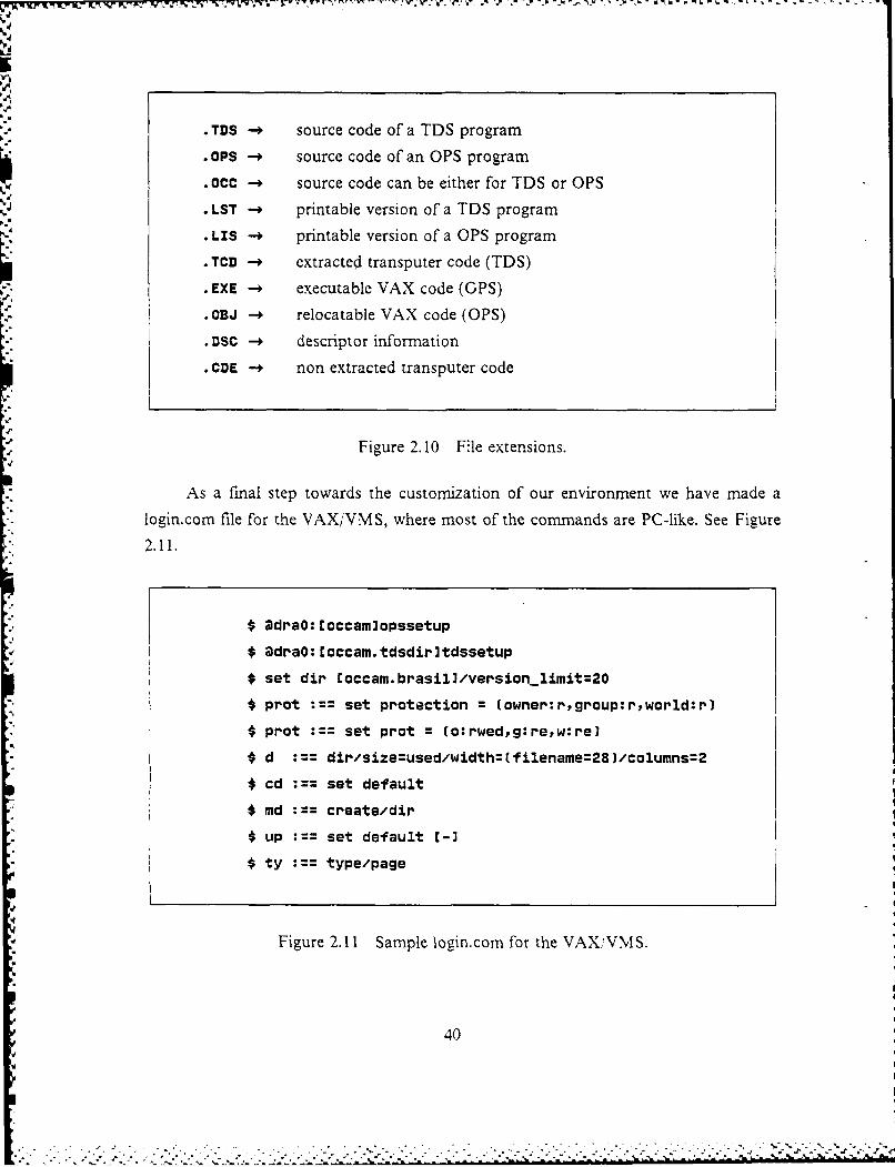
. TDS -. source code of a TDS program
.OPS - source code of an OPS program
. 0CC - source code can be either for TDS or OPS
. LST - printable version of a TDS program
. LIS - printable version of a OPS program
. TCD - extracted transputer code (TDS)
. EXE executable VAX code (GPS)
.OBJ - relocatable VAX code (OPS)
* uSc - descriptor information
.CDE - non extracted transputer code
Figure 2. 10 File extensions.
As a final step towards the customization of our environment we have made a
login.com file for the VAX/VMS, where most of the commands are PC-like. See Figure2.11.
$ @draO: Coccamlopssetup$ @draO: Coccam.tdsdir~tdssetup
I set dir Coccam.brasil]/version-limit:=20
prot set protection = (owner:rgroup:r,world:r)
prot set prot = (o:rwed,g:re,w:re)
$ d dir/size=used/width=(filename=281/columns=2
0 cd :== set default
$ md create/dir
S$ up set default E-3
$ty type/page
Figure 2.11 Sample logincom for the VAXiVMS.
40
S
-. . - . ,, - .. . . . . - , - . • - . . - - . - . - .- . . - - . . , - - - , - . . . - , :": '- ."."."."-" " ", :."... . .. . . . . . . . . . . . . . . . . . . . . . ..". . . . . ..". -I : " % ".'- , ; J F - ,I ' . "
I-'
III. OPERATING SYSTEM DESIGN
A. WHY AN OPERATING SYSTEM?As the program complexity increases and more processors are added to the
system. some hardware limitations become more critical and a series of new potentialsources of errors are added to the program. In the transputer case for example, the
four existent output channels will shortly become a bottleneck due to the increasingdemand in communications, forcing the programmer to change .he iogic of hisalgorithm to comply with the actual architecture. Another problem that will arise is S
how to route a message to a non ad]acent transputer in the network How to output to
the Screen from a remote transputer"
As widely known, the main purpose of any operating system is zo provide a userwith the ability to use the system or a family of systems, without having to know the
detailed hardware interconnections scheme for each specific system. In the specific caseof the transputer, we have tried to follow this same line of thought, and after some
reasoning, we have reached a very simple model for an operating system for a network
of transputers. In our model, the user will be able to use simple primitives like "send"
and "receive", to perform the necessary -intercommunication between processors. Themain idea behind this approach is to release the user from the obligation of taking careof the channels placements, and all other implications, which are derived from thislatter one. In other words, the user will not need to be concerned in how the messagewill get there.
Another feature, which was included in our model, is the capability of sendingtwo or more messages in parallel, to the same destination transputer, without having toassign or allocate several hardware links to handle this communication. The final goalis to make this another abstraction to the user, where the operating ;ystem would
multipiex the different messages through the same ihardware link, and this does not"imply inefficiency, since the destination transputer would have to handle the messagessequentially anyway, afterall it is still a single processor. S
Once we have given sufficient reasons to support our claim, that a sort of basicoperating system for a transputer network is vital, let's go into the other Section wherewe will try to cover all the steps of our design, in a very simple and practical way.
41
, . , .. . ... .. . ....... ,..... . ,-.. .... % .. ,..,-... .... ,. . -% .f5. ....... :'J,. ... ' ._. .. % .- -.

- i
B. THE DESIGN
Because of the fact that transputers have only local memory, a first approach and
probably the only one at the current state of the art, was to employ a distributed
operating system. An operating system kernel would reside in each node processor to
supervise the user processes running on the node and to handle message traffic.
The basic part of our design will be towards building an efficient communications
system, but we will also provide some I/O handling, as well as some utilities like getting
the real time, dumping memory, etc..., from "any transputer" in the network, which will
greatly enhance the overall debugging capability of the network, and it will make it
much easier to program.
One of the first design issues to arise was regarding the protocol to be used in
our communication subsystem, more specifically, what kind of information should be
carried by the message header.
The first needed information, and also the most obvious one, is the transputer id
number, which will identify the destination transputer for a message. This number, as
we will see later, must be in accordance with the routing table, since it will be used as
an index to retrieve information from this table.
The second information to be carried by the header is the message size, since we
have decided to support variable length messages. Here we had a trade off between
versatility (variable length), and efficiency (fixed length), but in this case we have
chosen to go towards the first one.
The third header component is not an obvious one, which is the channel id
number. It must be unique8 in the entire system. This channel id will allow the system
to determine within one transputer, which process, and ultimately, which channel is
supposed to receive that message.
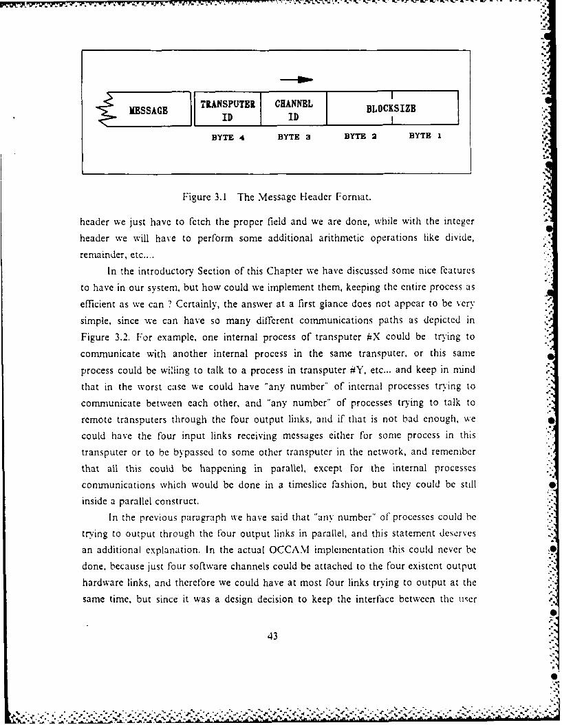
Therefore, the header which we will be using throughout our system is four bytes
long and has the format specified in Figure 3.1.
We could have used an integer value, which is also 4 bytes long, to carry all the header
information, but it would take too long to decode it, and besides, the time to output
four bytes with the BYTE.SLICE construct is approximately the same as to output an
integer [Ref. 9]. The difference in decoding time is because with the byte structured
8After looking at the implementation, it will become evident that the uniquenessof the channel id is a very important requirement, since otherwise it may lead todubious results. However, it could be eliminated if we have added another field, thetransputer origin, in the header of our protocol.
42
TD.ASPUTBR CHANNEL BIKUID ID BC B
BYTE 4 BYTE 3 BYTE 2 BYTE 1
4j.
I.
Figure 3.1 The Message Header Format.
header we just have to fetch the proper field and we are done, while with the integer
header we will have to perform some additional arithmetic operations like divide,
remainder, etc....
In the introductory Section of this Chapter we have discussed some nice features
to have in our system, but how could we implement them, keeping the entire process as
efficient as we can ? Certainly, the answer at a first glance does not appear to be very
simple, since we can have so many different communications paths as depicted in
Figure 3.2. For example, one internal process of transputer #X could be trying to
communicate with another internal process in the same transputer, or this same
process could be willing to talk to a process in transputer #Y, etc... and keep in mind
that in the worst case we could have "any number" of internal processes trying to
communicate between each other, and "any number" of processes trying to talk to
remote transputers through the four output links, and if that is not bad enough, we
could have the four input links receiving messages either for some process in this
transputer or to be bypassed to some other transputer in the network, and remember
that all this could be happening in parallel, except For the internal processes
communications which would be done in a timeslice fashion, but they could be still
inside a parallel construct.
In the previous paragraph we have said that "any number" of processes could be
trying to output through the four output links in parallel, and this statement deserves
an additional explanation. In the actual OCCAM implementation this could never be
done, because just four software channels could be attached to the four existent output
hardware links, and therefore we could have at most four links trying to output at the
same time, but since it was a design decision to keep the interface between the user
43
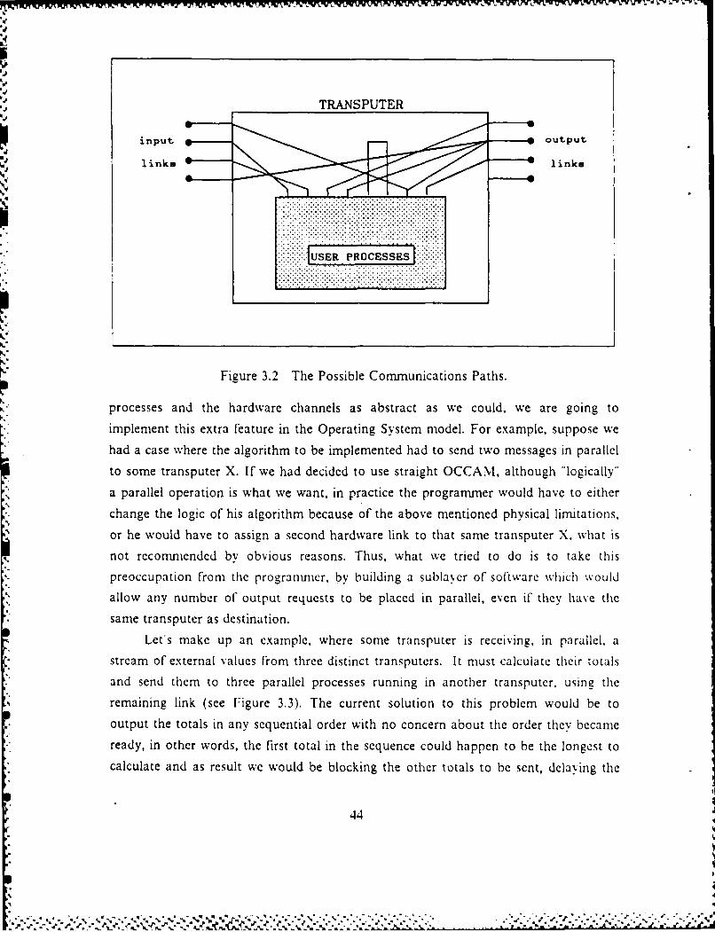
I7"
:. TRANSPUTER
input 9 output
links links
Figure 3.2 The Possible Communications Paths.
processes and the hardware channels as abstract as we could, we are going to* implement this extra feature in the Operating System model. For example, suppose we* had a case where the algorithm to be implemented had to send two messages in parallel
to some transputer X. If we had decided to use straight OCCAM, although "logically"a parallel operation is what we want, in practice the programmer would have to either
* ~change the logic of his algorithm because of the above mentioned physical liitations,or he would have to assign a second hardware link to that same transputer X. what isnot recommended by obvious reasons. Thus, what we tried to do is to take thispreoccupation from the programmer, by building a sublayer of so'tware which wouldallow any number of output requests to be placed in parallel, even if they have the
* same transputer as destination.Lets make up an example, where some transputer is receiving, in parallel, a
* stream of external values from three distinct transputers. It must calculate their totals* and send them to three parallel processes running in another transputer, using the
remaining link (see Figure 3.3). The current solution to this problem would be tooutput the totals in any sequential order with no concern about the order they becameready, in other words, the first total in the sequence could happen to be the longest to
calculate and as result we would be blocking the other totals to be sent, delaying the
,4
..
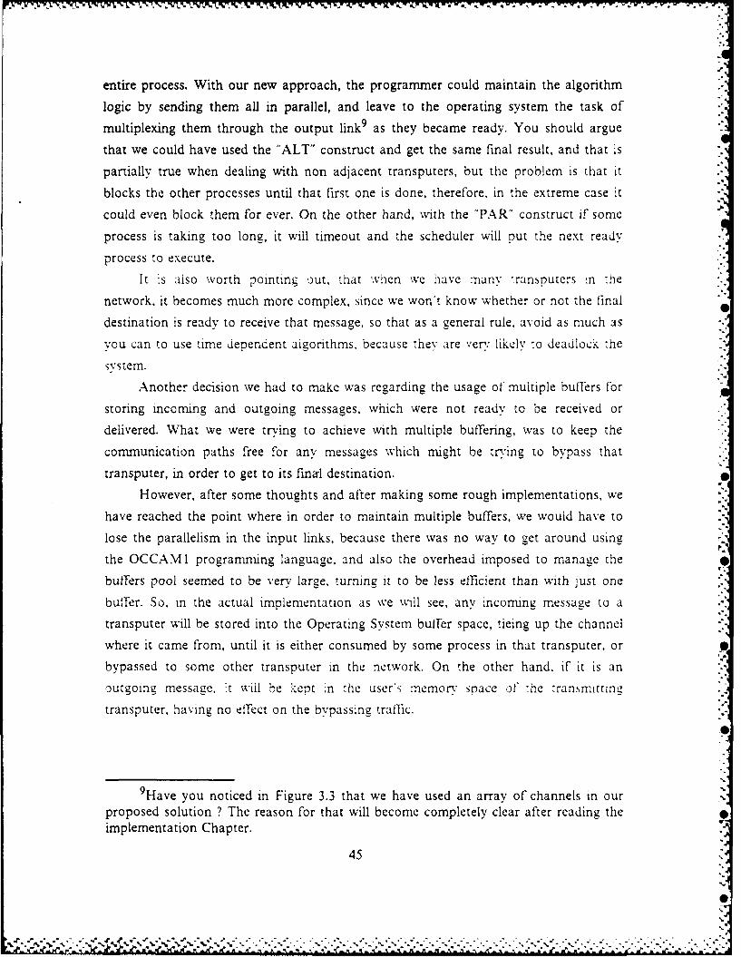
entire process. With our new approach, the programmer could maintain the algorithm
logic by sending them all in parallel, and leave to the operating system the task of
multiplexing them through the output link 9 as they became ready. You should argue
that we could have used the "ALT" construct and get the same final result, and that is
partially true when dealing with non adjacent transputers, but the problem is that it
blocks the other processes until that first one is done, therefore, in the extreme case it
could even block them for ever. On the other hand, with the "PAR" construct if some
process is taking too long, it will timeout and the scheduler will put the next ready
process to execute.
It is also worth pointing out, that when we have :nany -ransputers .n 'ie
network, it becomes much more complex, since we won't know whether or not the final
destination is ready to receive that message, so that as a general rule. avoid as much as
you can to use time dependent algorithms, because the" are ver likely to deadlock the
Mstem.
Another decision we had to make was regarding the usage of multiple buffers for
storing incoming and outgoing messages, which were not ready to be received or
delivered. What we were trying to achieve with multiple buffering, was to keep the
communication paths free for any messages which might be tr'ing to bypass that
transputer, in order to get to its final destination.
However, after some thoughts and after making some rough implementations, we
have reached the point where in order to maintain multiple buffers, we would have to
lose the parallelism in the input links, because there was no way to get around using -.
the OCCAMI programming language, and also the overhead imposed to manage the
buffers pool seemed to be very large. turning it to be less efficient than with Just one
buffer. So. in the actual implementation as we will see, any incomng messaae to a
transputer will be stored into the Operating System buffer space, tieing up the channel
where it came from, until it is either consumed by some process in that transputer. or S
bypassed to some other transputer in the network. On the other hand, if it is an
outgoing message. it will be kept in the user's memory space o" he transmittinlc,
transputer, having no effect on the bypassing traffic.
9Have you noticed in Figure 3.3 that we have used an array of channels in ourproposed solution ? The reason for that will become completely clear after reading theimplementation Chapter.
45
02
X'.,.'.-, .1 ".{.% :.".-'.:," .,"--v".q ". -.i 2"')'.''-.'-i i.;.- . .?--- ,--.---"- 2-.2-.--- . 2- -. .-'.-
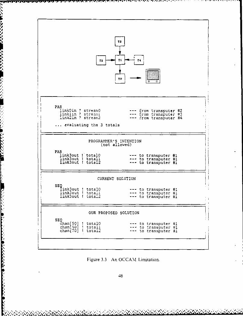
'P .. 'V 7w. TV 'i -7W.w V. W. V. k ".' 4P d.~'- ~ ' V' ~ - ~ ~ V . ~.
T3
PARlink0in ? streanio --- from transputer #2linklrn ? streami --- from transputer #3link2in ? stream2 --- from transputer #4
evaluating the 3 totals
PROGRAMIER'S INTENTION(not allowed)
PARlink3out I totalO --- to transputer #1link3out I totall --- to transputer #1link3out I total2 --- to transputer #1
CURRENT SOLUTION
SE?tink3out ! totalO --- to transputer #1link3out totail -- to transputer #1link3out I total2 --- to transputer #1
OUR PROPOSED SOLUTION
SEQchan [501 ! totalO --- to transputer #1chan[60] ! totall --- to transputer #1chanM[70] total2 --- to transputer #1
Figure 3.3 An OCCAM Limitation.
46d°

As you can see, we will have to deal with all kinds of mutual exclusion problems,
since we'll have in most of the cases many more parallel requests than available
resources (links), but here is where the transputer architecture, as well as the OCCAM
construct "ALTernate", become very handy. The first one by providing a built-in
process scheduler with two priority levels, a timer and a memory management unit, and
the second by providing a trivial solution to the mutual exclusion problem,' 0 as we will
see later in the next Chapter.
Now arises another problem, how could we route an incoming message to the
correct internal process it is supposed to be routed to ? One solution could be to
create in each transputer a channel-id table in memory (see Figure 3.4). where we
should have all the channels which conmmunicate with external transputers and one id
number associated with each of these channels. Obviously, the id number would have
to be carried by each message using that specific channel.
CHANNELS ID #
outO 10
hostinI 31
from.radar 18
in4 27
Figure 3.4 A Sample Channel-id Table.
Another solution that came up after some unsuccessful trials with the channel-id
table, and also a much better one in our opinion, is the idea of creating an array of
channels, where the id number could be the subscript of the array itself. Simple, is it
not ? Also this decision would make our mutual exclusion handler much simpler, as
you will see later in the implementation Chapter.
1I0 would like to emphasize that as you may recall, this is one of the most
traditional and difficult problems when building operating systems.
47
, % -. . - • - 7_ N . , , , .* " % " - ,,, - . ,, . • • .. - . ..- . "

As you can see, in our abstraction model we will have our Operating System with
the control of all the hardware link communications and with an user interface that will
allow the user processes to communicate with the outside world in a very simple way.
See Figure 3.5.
TRANSPUTER
NODE
input links OPERATING SYSTEM output links
USER INTERFACE
USER
PROCESSES
Figure 3.5 User Abstraction.
Therefore, based upon all the previous design decisions, our Operating System
will present the following characteristics:
* It will support a maximum of 256 transputers in the network, but since we areusing, for convenience, a routing table which supports only 18 entries, it will belimited to 18 transputers. This can be very easily modified, and it will beexplained in the Section covering the routing table.
* It will support a maximum of 256 user channels active at one time, forconununications with other transputers. Actual',; this number will drop to 20channels as well see in the implementation Chapter.
• it has no limit to internal soft channels.
• the maximum message length supported is 64 Kbytes.
As we can see, we have much more than we will really need for most typical
applications, so that our protocol could be very easily modified and optimized. In
Chapter VI we will evaluate two versions of the operating system, one with a 4 byte
header, and the other one with 3 bytes, and we will be able to see, very clearly, the
effect of the header size in the transfer rate.
48
..-" -." ." -... ". '- .'.'.---------------------------------------------------------------------------------------- , ,m~m~m
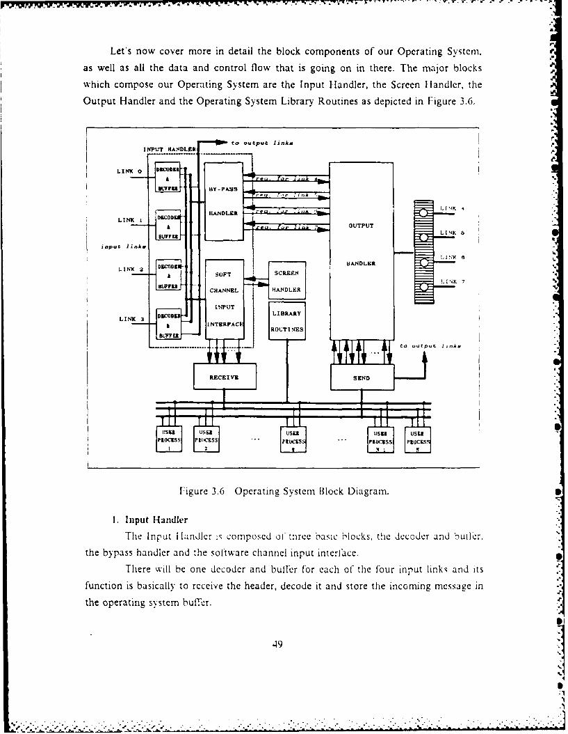
Let's now cover more in detail the block components of our Operating System,
as well as all the data and control flow that is going on in there. The major blocks
which compose our Operating System are the Input Handler, the Screen Htandlcr, the
Output Handler and the Operating System Library Routines as depicted in Figure 3.6.
to outpu t link s ,
INPUT HIANDLER /
LINK 6
BY -P SS o
H A N D L E R .I ,1 4
LINK I 60-- 9 r., ,, , , OUTPUT
LINK 7
Fiue36 prtn Sse lckDarm
input linkH
LIK2 OFT
SCREEN
LN
T nt CHANNEL HA o d DLER b
th praigsytmbuir
INPUTLDNK=
LIBRARY.o
ROUTINES
-------. to .uepu J -
RECEIVE SEND .'
Figure 3.6 Operating System Block Diagram.
1. Input Handler
The Input landlcr is composed of three basic blcks the decoder and bullcr.
the bypass handler and the sotware channel input interface.
There will be one decoder and buffer for each of the four input links and its
function is basically to receive the header, decode it and store the incoming message in
the operating system buffer,
,49, ,
The four bypass handlers will be activated by the respective header decoders,
upon arrival of a message to be bypassed, and then, they will issue a request to the
output handler, using a special soft channel, which will be uniquely identified by the
link from whicn the message is coming and by the link through which the message is
going to be forwarded, to get to its final destination. Once tne output handler accepts
its request, the bypass handler will release the decoder to go ahead with the
retransmission of the message by the desired link.
The software channel input interface will be activated just when the message :s
for that transputer. and it will perform an additional chleck to see if te message is
addressed to the Screen channel. in which case it xill request pernussion to me ,creen
handler to use its controlled resource. However, in both cases it will send the releasing
order back to the decoder, which will send the message either to the screen, or to the
appropriate channel in some waiting process.
2. Output Handler
This module is responsible for enforcing mutual exclusion in the four output
links. Basically it will handle two kinds of messages, the outgoing ones which are
generated by internal processes, and the bypassing ones which are coming from
external sources, and just want to use that transputer, as a retransmission station.
This module is always listening to all possible channels, in such a way that
any output request will be accepted almost immediately. Once a request for output in
some specific link is accepted, that means that the requestor can go ahead with the
transmission through that link, with the guarantee that no collisions will happen. As
you can see it acts much like an air controller in an airport with four parallel runways.
where besides ensuring mutual exclusion to each of the runways, he will keep them
working in parallel.
3. Screen Handler
The Screen Handler will make sure that just one process from "any transputer"
is holding control of the screen port at one time. Much like the output handler, once a
request is accepted. the requestor is guaranteed iree usage of the resource with rio
interference.
It is important to mention that all the communications between modules and
submodules of our operating system, are done strictly via control flags, with no data
flow until the very end of the process. Another point is that for efliciency purposes, we
are allowing some user accessible routines like "send" and "receive", to have direct
50

contact with the hardware links, but this will not cause any problems, because their
execution is completely controlled by the operating system modules.
V.-
7
51
0
-. p . .. -. ~ --..--.. - . . . - - - - - - - - - - - - - - - - - - - -

IV. OPERATING SYSTEM IMPLEMENTATION
We will discuss in this Chapter all the steps and peculiarities of our
implementation," as shown by the source code contained in the Appendix D.
A. INPUT HANDLER
The general structure of this module is presented in Figure 4.1, where we can seethat it is all the time listening to the four input links in parallel, and as soon as we
have any incoming message, it will be readily consumed by the proper link.
PROC input.handler =... variable and constant declarationsSEQSE. initializing the buffers
PARWHILE TRUE
listen to linkOWHILE TRUE
... listen to linklWHILE TRUE
listen to link2WHILE TRUE
... listen to link3
Figure 4.1 A General View of the Input Handler.
Hereafter, we recommend you to follow closely the source code contained in the
Figure 4.2 for a better understanding of the program. After receiving the header with
the BYTE.SLICE.INPUT built-in procedure, we start decoding the block size. You
should ask why to decode the block size right away, even before knowing if that
message is going or not to be bypassed, but as you will notice later, even for bypassing
the block size will be required.
Once we have stored the message in the buffer of the respective link, which is
maintained by the Operating System, we can proceed with the decoding. The buffersize is a very important issue, and it should be adjusted to the lengthiest message
l"At this point is highly recommended that the user have already been exposed tothe OCCAMI programming language and to the Transputer Development System forthe VAX, VMS.
52
% ? ," ;'' : ,-" "-: "", ,' . . :- :-:-: ' -' - - .- ..- , -. . . -: -.- , :> ,. . - . : ',:' :- ": -. -':. : : -,". ::L:. :.-

expected to travel in the network. This adjustment is carried out by changing the value
of the constant "max.block.size", located in the very top fold named "Operating System
Global Declarations" (see Appendix D). The reason for that is because the compiler
needs to allocate memory in advance for those buffers, and remember that we have one
buffer per input channel.
Since we have to spend an appreciable time initializing the buffers, 12 and also
because we have very strong memory limitations in the B001 board (64K), it is a wise
idea to use strictly the necessary buffer size. As we will see in Chapter VII, this buffer
size can be modified by changing a constant value called "max.block.size".
It' the message is not for this transputer we calculate the output link by looking
up in the routing table for that transputer. This table must be provided for each
transputer in the network during the configuration phase, it will be covered more in
detail at the end of this Chapter. But for the time being, it is sufficient to know that its
indexes are the destination transputers id numbers, and the correspondent values
represent the output channels to be used in order to reach those transputers.
Therefore, the only valid values in the table are 4, 5, 6 or 7.
So far we haven't done anything fancy, but now comes the subtle point, I may
say the most important and nice concept of the whole system. As you can see, when
we send a flag to the output handler, requesting a "green sign" to go ahead with the
retransmission of the header and the message, the soft channel used to send the flag
must carry the necessary information, in order for the output handler to be able to
recognize specifically, who is requesting permission, and which output link that request
is for. The reason it must keep track of information like this is because many different
users might be requesting permission to output through the same link. Now comes the
question: how can we pass this information to the output handler without having to
send extra bytes of information, and at the same time keeping this switching of
processes as efficient as we can ? The answer we came up with was to use an array of
channels whose indexes obeyed a special law of formation.
If 'ou take a close look at the code, you will see that the channel indexes will
carry all the needed information, in other words, who is requesting and what is being
requested. So that. channels 04, 05, 06 and 07 will be used by any message received
through link 0 tihat wants to be retransmitted by links 4, 5, 6 or 7 respectively.
'Although this is not a required step, it is believed that in not doing it, we mayhave some strange results, due to some problems i the code generation of theOCCAM I compiler for the VAX.
53
VS
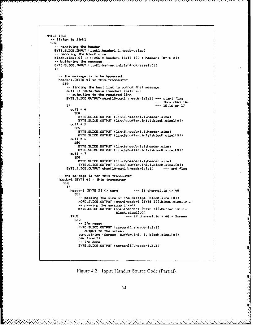
WHILE TRUE-- listen to linki
SEQ receiving the header
BYTE.SLICE.INPUT (linkl,headerl,1,header.size)-- decoding the block sizeblock.sizelLO] z((256 * headeri (BYTE 1]) + headeri [BYTE 2])
-buffering the messageBYTE.SLICEAINPUT tlinklibuffer.inl,lpblock-sizel[0])IF
-- the message is to be bypassedheaderl-[BYTE 4] -> thistransputar
SEQ-finding the best link to output that message
outl :=routetable Eheaderi [BYTE 4]]-outputing to the required link
BYTE.SLICE.OUTPUT(chan[10+outl,headerl,3,l)-- start flag-- thru chan 14,
IF -- 15,16 or 17outl =4
SEQBYTE.SLICE.OUTPUT (link4,headerl,l ,header. size)BYTE.SLICE.OUTFUT (link4,buffer.inl,l,block.sizel[0])
outl = 5SEQ
BYTE.SLICE.0UTPUT (linkS,headerl,l,header.size)BYTE.SLICE.OUTPUT (link5S,bufferdinl,1,block.sizell0])
outl =6SEQBYTE.SLICE.OUTFUT (link6,headerl,l,header.size)BYTE.SLICE.OUTPUT (link6,buffer.inl,l,blocksizel(O])
outl = 7SEQ
BYTE.SLICE.0UTPUT (linkl headerl,l,header.size)BYTE.SLICE.OUTPUT (linkl,buffer.inl,l,block.sizel[0]J
BYTE.SLICE.0UTPUT(chan~l0+outl,headsarl,3,l) -- end flag
-the met sage is for this transputerheaderl [BYTE 4] thistransputer
SEQIFheaderl [BYTE 3] <> scm -- if channel.id <> 403
SEQ-- passing the size of the message (blooksizeltO])NORO.SLICE.OUTPUT (chantheaderl [BYTE 3]] ,blocitsizel,0,l)-- passing the message itselfBYTE.SLICE.OUTFUT (chan[headerl [BYTE 3]],buffer.inl,l,
block.sizel[0])TRUE -- if channelid =40 = Screen
SEQ-- I'm readyBYTE.SLICE.OUTFUT (screen[l],headerl,3,l)
-output to the screensend.string (Screen, buffer.inl, 1, block.sizel[O])new linedl)-- I'm doneBYTE.SLICE.OUTPUT (screentl],headerl,3,l)
Figure 4.2 Input Handler Source Code (Partial).
54
. . - ... . --- .-
Likewise, channels 14, 15, 16 and 17 will be related to link 1, channels 24, 25, 26 and
27 to link 2, and finally channels 34, 35, 36 and 37 to link 3. Therefore, these will be
operating system reserved channels and must not be used as user channels. Remember,
there will be no checking for this error, so that if you use these channels inside your
program it will very likely deadlock the system.
When the retransmission of the message is finished, the requestor sends another "'"
flag to the output handler, to let it know that the output link may be freed or used by
the next in the queue.
On the other hand, if the message is for this transputer, then a further check will
be made to see if the message is to be sent to the screen or to some internal user
process. This check is needed because in our implementation a message sent to the
screen does not require a receiving process in the root transputer, whereas in the other
case it is mandatory. Obviously this step will be carried out just in the root transputer.
and this will be the basic difference between the operating system for the root and for
the other transputers, since the root transputer is the only one to have a port attached
to a terminal.
When the message is for some user process, the block size information is still
needed, since the user process must know what is the length of the message it is about
to receive, otherwise it will have no way to know when to stop receiving. This
additional overhead arises from the fact that we are allowing variable length messages.
The screen channel is defined as channel "scrn" or "40", and it is another
operating system reserved channel. Once we receive any message addressed to it, we
will need to request permission to the screen handler, as we have done previously with
the output handler, to go ahead and send it to the terminal.
B. OUTPUT HANDLER
Although the Output Handler looks very simple, it performs a very complicated
task which is to assure mutual exclusion for each one of the output links.
As can be seen in Figure 4.3, all the channels with termination 4 will be polled
through the first OCCAM alternate construct (ALT) to check if there is anyone
requesting access to link 4. Similar action is being held for each of the others output
links, with all of this being done in parallel. If there is any request for output through
the hardware links, it will accept the request and will lock up that link until the user
tells him that he is done. The main issue here is that the termination of the soft
channel id, determines which link that channel wants to use as output.
55
Lee
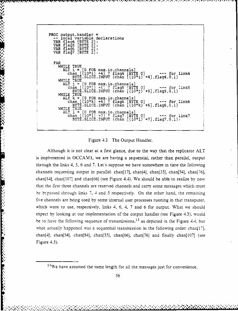
,%
PROC output.handler =-- local variable declarationsVAR flag4 [BYTE 23VAR flag5 [BYTE 2VAR flag6 [BYTE 2 :VAR flag7 [BYTE 2:
PARWHILE TRUE
ALT i = [0 FOR max.io.channels]chan [(10*i) +4] ? flag4 [BYTE 0] for link4
BYTE.SLICE.INPUT (chan [(10*i) +4],flag4,0,1)WHILE TRUE
ALT j = [0 FOR max.io.channels]chan [(10*k) +5] ? flag5 BYTE 0] for link5
SWHILE TRUEALT k = [0 FOR max.io.channels]
chan [(10*k) +6] ? flag6 [BYTE 0] for link6BYTE.SLICE.INPUT (chan [(10*k) +6],fl;g6,0,!)w.', HILE TRUE-"ALT 1 = [0 FOR max.io.channels]""chan [(I0*i) +7] ? flag7 [BYTE 0] - for link7
BYTE.SLICE.INPUT (chan [(10*1) +7],flag7,0,1):
Figure 4.3 The Output Handler.
Although it is not clear at a first glance, due to the way that the replicator ALT
is implemented in OCCAMI, we are having a sequential, rather than parallel, output
through the links 4, 5, 6 and 7. Let's suppose we have somewhere in time the following
channels requesting output in parallel: chan[17], chan[4], chan[35], chan[54], chan[76],
chan[S-], chan[107] and chan[66] (see Figure 4.4). We should be able to realize by now
that the first three channels are reserved channels and carry some messages which must
be bypassed through links 7, 4 and 5 respectively. On the other hand, the remaining. five channels are being used by some internal user processes running in that transputer,
which want to use, respectively, links 4, 6, 4, 7 and 6 for output. What we should
expect by looking at our implementation of the output handler (see Figure 4.3), would
be to have the following sequence of transmissions, 13 as depicted in the Figure 4.4, but
what actually happened was a sequential transmission in the following order: chan[17],
chan[4], chan[54], chan[841, chan[351, chan[66], chan[76] and finally chan[107] (see
Figure 4.5).
13We have assumed the same length for all the messages just for convenience.
56
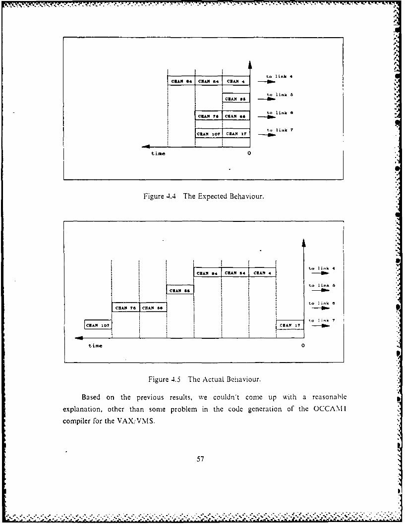
r
S.
I i i
S C Cto link 4
to link 5ClAN 8S
to link 8CRA _7 ClAN 66
1 to link 7CRAN 107 ClAN 17
time 0
Figure 4.4 The Expected Behaviour.
A 4to link 4* I CRAM 34 ClAN4 ClAN
I to link a
*to link 6
C Cto I nk
time 0
Figure 4.5 The Actual Behaviour.
Based on the previous results, we couldn't come up with a reasonable
explanation, other than some problem in the code generation of the OCCAM I
compiler for the VAX/VMS.
57
*', . ...... .. .-.-..... -........ ... - .. .. . -. .#. ...... ...... ''.

-IiwV-J JAfter many different trials we have Finally got a way to implement it truly in
parallel, and it came up with the odd structure presented in Figure 4.6.
WHILE TRUESEQ
goingi TRUEgoing2 TRUEgoing3 TRUEFoing4 TRUE
WHILE goingiALT
ALT j=[0 FOR max.actual.channels]chan [(10*j)+4] ? flagl
SKIPgoingi : FALSE
WHILE going2ALT
ALT k =0 FOR max.actual.channels]chan rR(1*k)+s51 ? fla 2SKPBYT2.SLICE.QUTPUT ciian((1O*k)+5],f1ag2,1,1)
going2 :=FALSE
WHILE going3ALT
ALT 1 = [0 FOR max.actual.channels]
SKIP Y.SIEO)PTca(1*)],ac311going3 :=FALSE
WHILE going4ALT
ALT mn = [0 FOR iax.actual.channels]chan [1O*m)+7] ? flaq4BYTE.SLICE.OUTPUT(chan((1O*m)+7,flag4,.,1)
SKIPgoing4 :=FALSE
Figure 4.6 The Parallel Solution.
However, this was the only way we round to trick the compiler. With this structure we
had the expected parallel output, in other words, each 'ink :ransrnitting in parallel.
exactly like depicted in Figure 4.4.
If the reader looks at the final implementation of the Output H-andler. he willnotice that we have used the first structure, rather than the second one. There are some
reasons for that, the first one is because we have assumed that it will be very unlikely.
to have such a situation where all the channels will be ready exactly at the same time
58
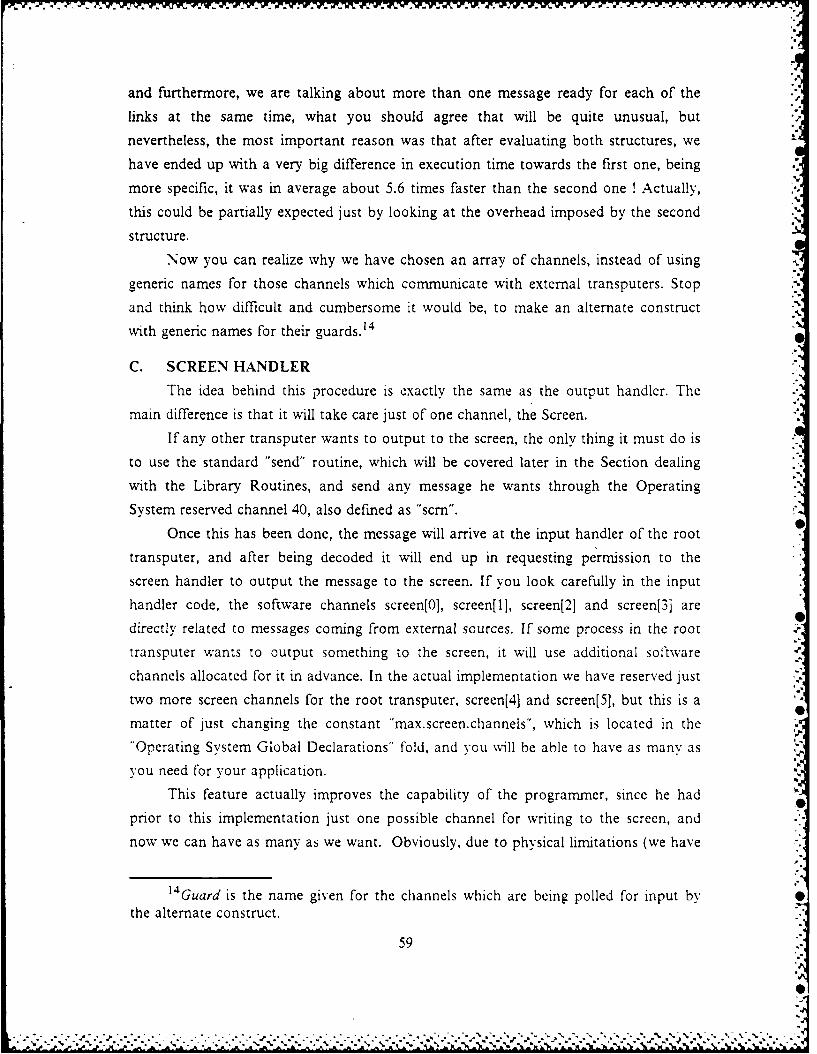
and furthermore, we are talking about more than one message ready for each of the
links at the same time, what you should agree that will be quite unusual, but
nevertheless, the most important reason was that after evaluating both structures, we
have ended up with a very big difference in execution time towards the first one, being
more specific, it was in average about 5.6 times faster than the second one ! Actually,
this could be partially expected just by looking at the overhead imposed by the second
structure.
Now you can realize why we have chosen an array of channels, instead of using
generic names for those channels which communicate with external transputers. Stop
and think how difficult and cumbersome it would be, to make an alternate construct
with generic names for their guards. 14
C. SCREEN HANDLER
The idea behind this procedure is exactly the same as the output handler. The
main difference is that it will take care just of one channel, the Screen.
If any other transputer wants to output to the screen, the only thing it must do is
to use the standard "send" routine, which will be covered later in the Section dealing
with the Library Routines, and send any message he wants through the Operating
System reserved channel 40, also defined as "scrn".
Once this has been done, the message will arrive at the input handler of the root
transputer, and after being decoded it will end up in requesting permission to the
screen handler to output the message to the screen. If you look carefully in the input
handler code, the software channels screen[0], screen[l], screen[2] and screen[3] are
directly related to messages coming from external sources. If some process in the root
transputer wants to output something to the screen, it will use additional sof'tware
channels allocated for it in advance. In the actual implementation we have reserved just
two more screen channels for the root transputer, screen[4] and screen[5], but this is a
matter of just changing the constant "max.screen.channels", which is located in the
"Operating System Global Declarations" fold, and you will be able to have as many as
you need for your application.
This feature actually improves the capability of the programmer, since he had
prior to this implementation just one possible channel for writing to the screen, and
now we can have as many as we want. Obviously, due to physical limitations (we have
14'Guard is the name given for the channels which are being polled for input bythe alternate construct.
59
0,-
just one port to the monitor), we will have a sequential output, but in doing so we are
taking from the user the need to worry about this matter, in other words, we are
providing to the user a higher level of abstraction.
However, the beauty of all this about the screen, is that we have now theI, possibility of debugging remote transputers, what we didnt't have before. Now we can
even trace the execution of all our processes running in the entire network, by just
sending a flag to the screen when entering in some procedure and when exiting it. Of
course it won't be in real time, but at least we will be able to have a precise idea of theentire flow of control in the network.
If we have the case where four transputers may try to output to the screen at the
same time, we won't know which is which, so that we must send a unique message
which characterizes the transputer it is coming from. This little problem could be very
easily solved by inserting the origin transputer id in the message header, but for
efficiency purposes we decided not to implement it.
Finally, you might have already noticed that the output to the screen from
remote transputers, is the only send operation which does not require any other receive
operation in the root transputer. This is a basic point, since for every send operation
ought to have a receive operation for the same channel id somewhere in the network,
otherwise the system will deadlock.
D. THE ROUTING TABLE
The routing table is the instrument that will provide to the operating system, the
necessary information regarding the routing of messages. For example, if we receive a
message which needs to be bypassed, the O.S. based on the destination transputer id
for that message, will look up in the table and see which is the recommended link to
output that message. Once this has been determined, it will follow the standard steps to
input or output a message, as already discussed in previous Sections. Similar action
will be taken for internal messages, which want to be forwarded.
In the first implementation of our system, we put the routing table, as well as the
transputer id number, as global variables inside each of the SC PROCs to be
downloaded to the network. Although this way is much simpler to implement, it
presents a very serious limitation, and that happens when we want to load basically the
same SC PROC in several transputers, just differing by its id number and by its routing
table. If that was the case we would have to make as many as needed different SCs,
which is completely wasteful. So, we decided to pass the transputer id number and the
60
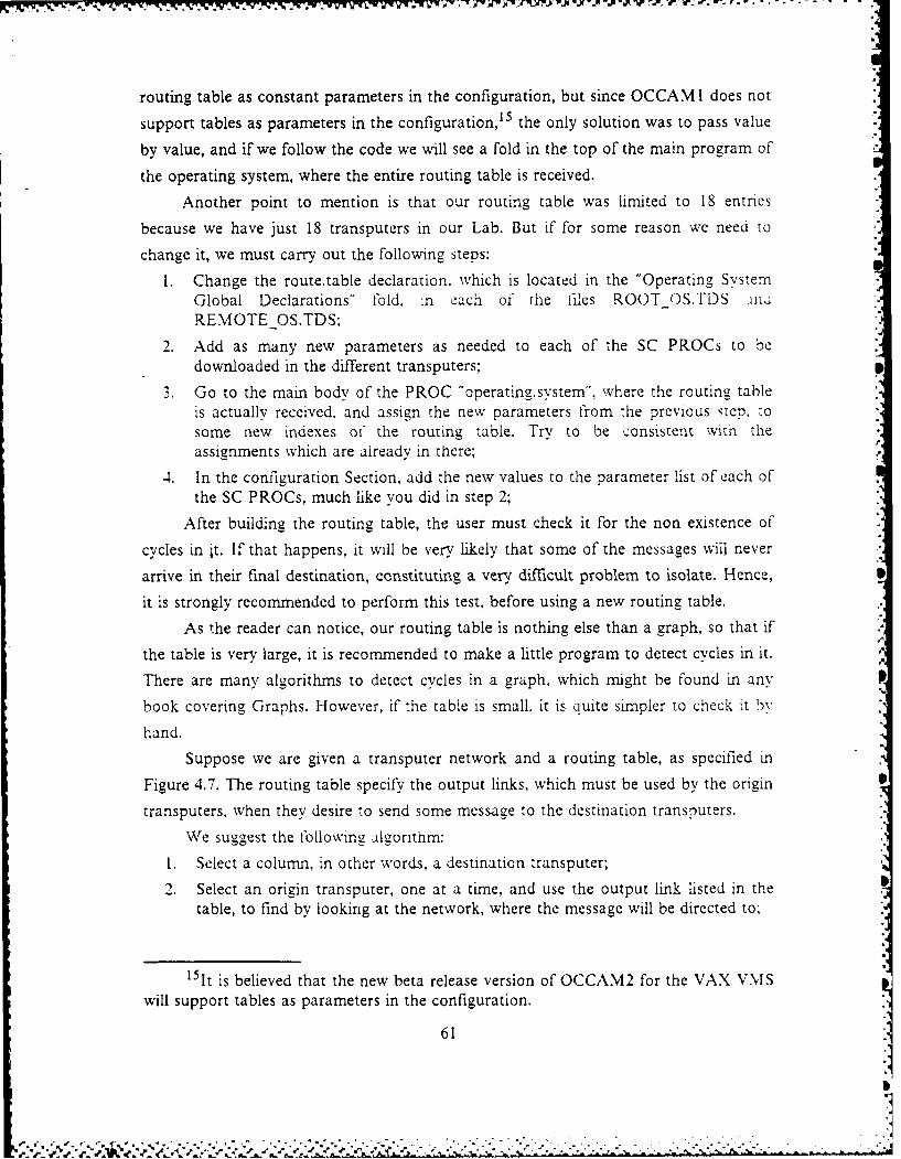
routing table as constant parameters in the configuration, but since OCCAM I does not
support tables as parameters in the configuration, 5 the only solution was to pass value
by value, and if we follow the code we will see a fold in the top of the main program of
the operating system, where the entire routing table is received.
Another point to mention is that our routing table was limited to 18 entries
because we have just 18 transputers in our Lab. But if for some reason we need to
change it, we must carry out the following steps:
I. Change the route.table declaration, which is located in the "Operating SystemGlobal Declarations" fold. in each of the files ROOTOS.TDS .inuREMOTE OS.TDS
2. Add as many new parameters as needed to each of the SC PROCs to bedownloaded in the different transputers; .
3. Go to the main body of the PROC "operating.system", where the routing tableis actually received, and assign the new parameters from the previous step, -osome new indexes of the routing table. Try to be consistent with theassignments which are already in there;
4. In the configuration Section, add the new values to the parameter list of each ofthe SC PROCs, much like you did in step 2;
After building the routing table, the user must check it for the non existence of
cycles in it. If that happens, it will be very likely that some of the messages wil never
arrive in their final destination, constituting a very difficult problem to isolate. Hence,
it is strongly recommended to perform this test, before using a new routing table.
As the reader can notice, our routing table is nothing else than a graph, so that if
the table is very large, it is recommended to make a little program to detect cycles in it.
There are many algorithms to detect cycles in a graph. which might be found in any
book covering Graphs. However, if the table is small. it is quite simpler to check it by
hand.
Suppose we are given a transputer network and a routing table, as specified in
Figure 4.7. The routing table specify the output links, which must be used by the origin
transputers, when they desire to send some message to the destination transputers.
We suggest the following aigorithm:
1. Select a column, in other words, a destination transputer;
2. Select an origin transputer, one at a time, and use the output link listed in thetable, to find by looking at the network, where the message will be directed to.
151t is believed that the new beta release version of OCCAM2 for the VAX, VMS
will support tables as parameters in the configuration.
61
3. If the transputer obtained from Step 2, is not the destination transputer, jumpback to Step 2 and use the latter one as the new origin transputer, otherwise,proceed to Step 4;
4. If you have got a cycle when executing Steps 2 and 3 stop, modify the routingtable, and start all over again, otherwise, jump back to Step 1 and selectanother column, until all columns have been selected.
E. OPERATING SYSTEM LIBRARY ROUTINES
What do these libraries contain ? Is it required to put them in any TDS program?
As explained in Chapter II, the answer is "no". They are not required to be inside a
file, a [old or whatever, but this was the way we found most attractive, logical and
easy, to handle the increasing number of new procedures, which were created along our
research. The basic idea is to update the library whenever someone in the research
group, has made a routine which might be useful in the future. However, it will be
useless if it is not very well documented, tested and validated for all expected inputs.
Following this line of thought we have built basically two libraries. :he first one
for the root transputer, and the second one for remote transputers. Both are completely
described within Appendices D and E, which present the source code for the root and
remote operating systems.
Although they have almost the same routines, they have quite a few differences
in their implementations, as we should expect. However, it is not our intention to
provide a deep explanation of all the code contained in those libraries, but the
interested reader is welcome to go into the source code, which we have tried to
document as well as possible.
The only routines which we will cover in detail are the "send" and "receive"
routines, which are the basic interface to the user, "nd also the most important
procedures to handle communications in the network.
1. The Send Routine
When we want to send a message to an external transputer, this is the right
procedure to call. It is one of the two only routines, which can access the modules of
the operating system directly. It is also, as we will see later, the only routine .hat can
output directly to the hardware channels, but obviously under control of the operating
system. The fact that we are allowing a user accessible routine to talk directly with the
hardware output link, may cause the unpleasant feeling that we are not following our
previous abstraction model for our system, but that is not correct, since the operating
system is still with the control over that link. Furthermore, we have tried other wavs
and this was by far the most efficient one.
62
. l"I -"I rl * S . I II 1 I I I1 - r :: - C t. I #- -
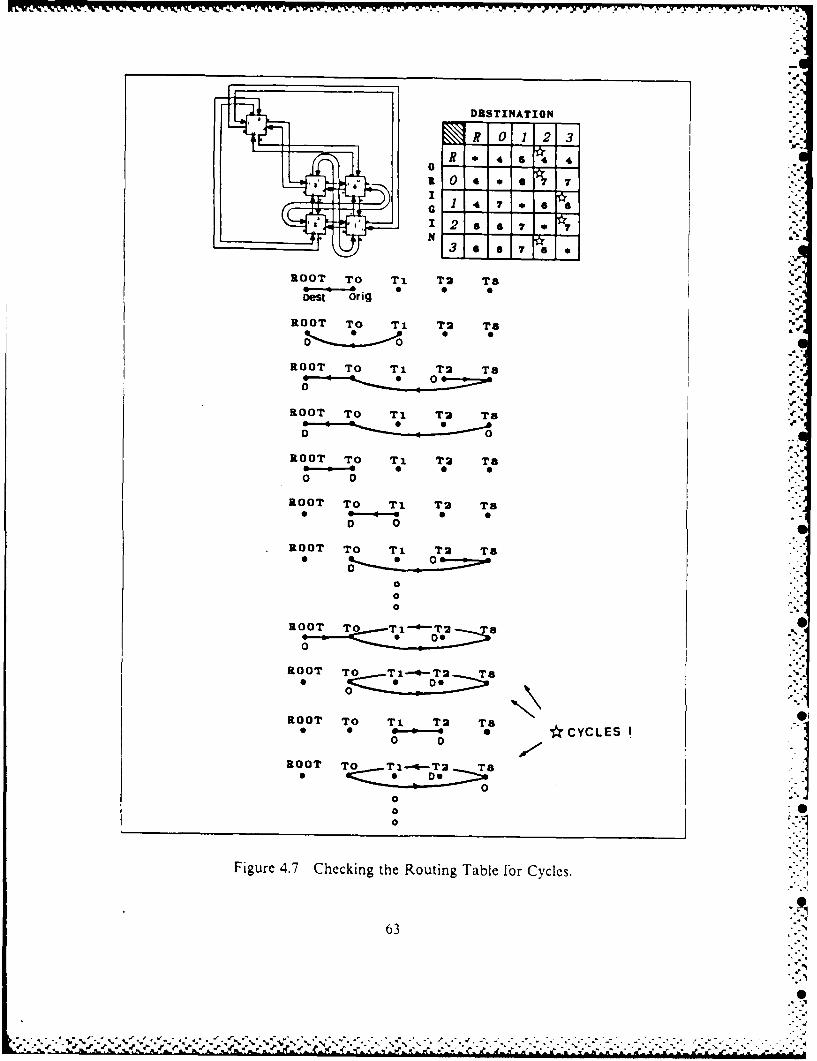
DRSTINATION
R 0123
R 0 4 a 7
04 7 4 6 7GS
ROOT TO Ti T2 TS
oest orig
ROOT TO Ti T2 TS
ROOT TO Ti T2 T'
ROOT TO Ti T2 Ta
ROOT TO Ti T2 Ta
0 0
ROOT To Ti T2] T8O 0
ROOT TO Ti T2 TaD 0
0ROOT To Ti T3 T a
00
ROOT To T8-4-T2 -
0
ROOT To T T 2 T8
• ~ ~ ~ ' * -.e-- CYCLES
0
ROOT TO Ti-*-T2 T"0
o
Figure 4.7 Checking the Routing Table for Cycles.
63
- o • - -. .. .. -; i; ,,I llliib kl = & dll ,'l' I. . ...kli mli m
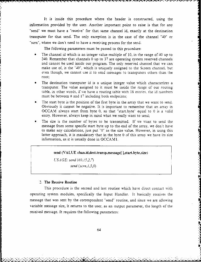
It is inside this procedure where the header is constructed, using the
information provided by the user. Another important point to raise is that for any
"send" we must have a "receive" for that same channel id, exactly at the destination
transputer for that send. The only exception is in the case of the channel "40" or
"scrn", where we don't need to have a receiving process for the send.
The following parameters must be passed to this procedure:
* The channel id which is an integer value multiple of 10, in the range of 40 up to240. Remember that channels 0 up to 37 are operating system reserved channelsand cannot be used inside our program. The only reserved channel that we canmake use of, is the "40", which is uniquely assigned to the Screen channel, buteven though, we cannot use it to send messages to transputers others than theroot;
* The destination transputer id is a unique integer value which characterizes a
table. in other words, if we have a routing table with 18 entries, the id numbers
must be between 0 and 17 including both endpoints:
• The start byte is the position of the first byte in the array that we want to send.Obviously it cannot be negative. It is important to remember that an array inOCCAM always start from byte 0, so that "start.byte" equal to 0 is a validentry. However, always keep in mind what we really want to send;
* The size is the number of bytes to be transmitted. If we want to send themessage from some specific start byte up to the end of the array, we don't haveto make any calculations, just put "0" as the size value. However, in using thislatter approach, it is mandatory that in the byte 0 of this array we have its sizeinformation, as it is usually done in OCCAM 1.
send (VALUE chan.id,dest.transp,message[ ],start.byte,size)
USAGE: send (60.15,27)
send (scrn,1,5,0)
2. The Receive Routine
This procedure is the second and last routine which have direct contact with
operating system modules, specifically the Input Handler. It basically receives the
message that was sent by the correspondent "send" routine, and since we are allowing
variable message size, it returns to the user, as an output parameter, the length of the
received message. It requires the following parameters:
64
p.
Ir
* The channel id which is an integer value, multiple of 10, in the range of 50 upto 240. Much likely the "send", we cannot use the operating system reservedchannels, and with the "receive", not even the "scrn" channel or "40" isaccepted;
* This parameter is an output parameter of the type array, and contains thevariable to hold the incoming message, which must be declared as an array ofthe same type of the original message:
* The last parameter is also an output parameter and provides the user with thelength of the message just received. It is included as a parameter, because wemight have a case where the program must take an action based on :he lengthof the message, but in most o the cases it can be disregarded. It must bedeclared as an array of integers with size 1.
receive (VALUE channel.id, VAR message[ ],message.length[ ])
USAGE: receive '60.message.'n.wize)
3. The Root Library (ROOTLIB.TDS)
This Library is intended to be used under the Operating System in the root
transputer. It contains basically many 1, 0 routines with various formatting capabilities,
some conversion routines to change the representation of some data types, and some
utilities which will help you in getting the real time inside some process, to calculate
the transfer rate in KBitsisec of some link, to dump parts of memory for debugging
purposes, etc....
Unfortunately, the file system interface with the VAX. VMS is not supported
by the OPS Kernel in OCCAM I. and although we have put some effort in solving this
problem, we didn't have the sufficient time to get a successful result. This issue will be
discussed later in the Section covering follow-on'work, in Chapter VII.
The Appendix D will present the operating system for the root transputer, and
in there, you will be able to find the filed fold ROOT LIB.TDS. with all the routines init.
-4. The Remote Library (REMOTE LIB.TDS)
The basic difference between both libraries is that in the first one, we can send
anything directly to the screen, after receiving the consent of the Screen Handler,
whereas in the second, we must always use the procedure "send", by the special channel
"40" or "scrn". Another difference is that in the second library, we don't have the
65
. . .. . ... . . .0
................ .7..................... . .
1.
r.
PROC rem.write.string, simply because the PROC send performs the same function,with even some more enhancements. Finally, we don't have the PROCs rem.read.stnng
and rem.read.number, which use the channel Keyboard for input. They were not
implemented because of time constraints in our schedule, but we will give a brief
suggestion for their implementation, in the Section covering "follow-on work".Similarly, the REMOTEOS.TDS which is presented in Appendix E, will
contain the REMOTELIB.TDS as a tiled fold.
66
7I

A. INTRODUCTION .w."
This Chapter will be devoted to one of the main issues, when dealing with
-:
programs which are supposed to run under a real time environment, and that is its.1pFerformance evaluation".:J.
The evaluation will be basically software oriented, in the sense hat no hardware ,measurements will be made. Strictly speaking, it will consist in running a special ."program, where all links will be exercised in transmitting messages of different sizes,and where the parallel operation of the links will be stressed as well."'
B. A BRIEF DESCRIPTION OF THE EVALUATION SYSTE
"'
The configuration on which we are going to evaluate our operating system,. is"'composed of a root transputer directly connected to four others transputers, aspresented in Figure 5.1. The program used for the evaluation is a modification of theevaluation program made by Vanni J.F. in his thesis [Refs 9, where a completeevaluation of the Transputer and its communications links is presented. We will be
using eve the same configuration, in such a way, that our final results for the link
transfer rates, when using the Operating System, can be fully compared with his results. "Basically, what his program does is to send successively to one transputer, then
to two, three, four and forally to all transputers in parallel, messages with vat'ing sizes,starting from g byte up to 10000 bytesVn6 After receiving these messages the remote
transputers will echo them back, also in a parallel fashion and the root transputer aftera veryn careful and precise timing process, will time the entire transfer process anddisplay the transfer rate in KBits/sec.
The structure of this evaluation program can be better understood, if stated as asequence of steps, where each complete sequence will be applied, consecutiveswt foreach message size. We will also present in Figure 5.2 a partial view of the evaluation
program, which will be running in the root transputer.
ae In our modified version of his program, wwilltie ell ene tnsted to a maximummessage sizeof 4K, due to 001 board memo" limitations, which are aggravated bthe fact that the Operating System must maintain a series of buffers in addition to theuser declared ones.
67 i'
".N
..
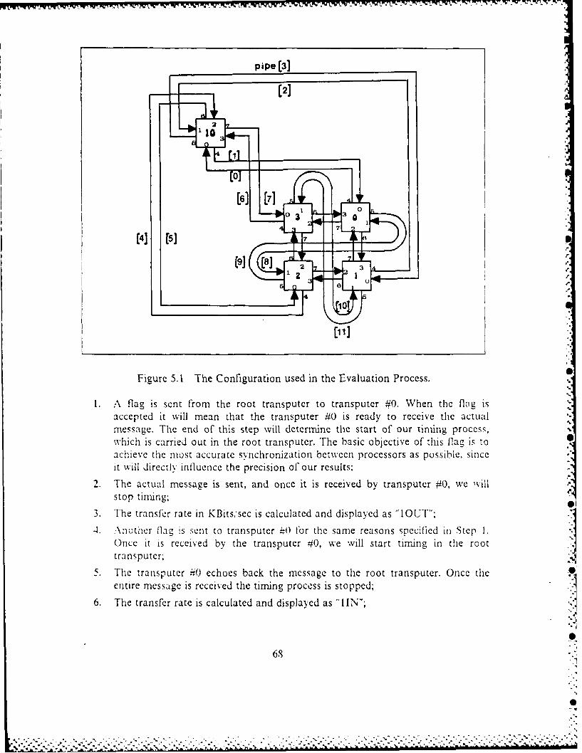
-7IL -?~ II - -V .1. VI Ar .V.
pipe [3]
[2]2
[6] [7]
[091(4] [57
p
Figure 5.1 The Configuration used in the Evaluation Process.
A flag is sent from the root transputer to transputer #0. When the flag isaccepted it will mean that the transputer #0 is ready to receive the actualmessage. The end of this step will determine the start of our timing process,which is carried out in the root transputer. The basic objective of this flag is toachieve the most accurate synchronization betwccn processors as possible, sinceit will directly influence the precision of our results:
2. The actual message is sent, and once it is received by transputer #0, we willstop tining;
3. The transfer rate in KBits,'sec is calculated and displayed as "1OUT";
-4. .\nother flag is sent to transputer -0 for the same reasons specified in Step I.Once it is received by the transputer #0, we will start timing in the roottransputer;
5. The transputer #40 echoes back the message to the root transputer. Once theentire message is received the timing process is stopped;
6. The transfer rate is calculated and displayed as "IIN;
0
68
.0.
................... ~..--- ... .... ...
7. Two flags are sent in parallel to transputers #0 and #1. Upon arrival we starttiming;
8. The message is sent to both transputers, in parallel, by 2 different links. Uponarrival of both messages we stop timing;
9. The transfer rate is calculated and displayed as "2OUT";
10. Two more flags are sent in parallel to transputers #0 and #1. Upon arrival westart timing;
11. The messages are echoed back by both transputers. Upon arrival of bothmessages in the root transputer, we stop timing;
12. The transfer rate is calculated and displayed as "2IN";
13. Three ilags are sent in parailel to transputers ;,0, #1 and =2. Upon arrival westart timing;
14. The message is sent to the three transputers, in parallel, by 3 different links.Upon arrival of the messages we stop timing;
15. The transi'er rate is calculated and dispiaved as "3OUT":
16. Three more tlags are sent in parallel to transputers 40 #1 and =2. Upon arrivalwe start timing;
17. The messages are echoed back by the transputers. Upon arrival of all messagesin the root transputer, we stop timing;
18. The transfer rate is calculated and displayed as "3IN":
19. Four flags are sent in parallel to transputers #0, #1, #2 and #3. Upon arrival westart timing;
20. The message is sent to the four transputers in parallel by 4 different links. Uponarrival of the messages we stop timing;
21. The transfer rate is calculated and displayed as "4OUT";
22. Four more flags are sent in parallel to transputers 40, 41, =2 and =3. Uponarrival we start timing;
23. The messages are echoed back by the transputers. Upon arrival of all messageswe stop timing;
24. The transfer rate is calculated and displayed as "4IN";
25. Four flags are sent in parallel to transputers 0 1. =2 and 13. Upon arrival westart timing;
26. The message is sent to the four transputers. in parallel. by 4 different links, andthey will echo them back immediately. Upon return of the four messages at theroot transputer, we will stop timing. This step is carried out just to check theperformance when all 8 channels (2 per link), are working in parallel;
27. The transfer rate is calculated and displayed as "4INOUT":
69
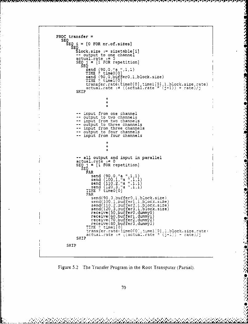
N~~J~X~FUVXN'..9flj~~~jV~~tiWVV V. VWWV-VVY, g ~~w-.~~ ~~- ~ .
PROC transferSE~ ?E2 = [0 FOR nr.of.sizesl
gloc~siz :=sizetableti]-- output to one channelactual.rate :=0SE? j = [1 FOR repetition]
send (90,0,"a "11.)TIME ? timeo[O1send (90,0,buffer0 ,l, bloc}k.size)TIME ? timel[O]transfer.rate(time0[0] timel[0] ,l,block.size rate)actual.rate :=((actual.rate *(J-)) + rate$/j
SKIP
0
-- nout from one channel-- outtout to two channels-- npuit from two channelIs-output to three channels-input from three channels-output to four channels-input from four channels
-all output and input in parallelactual rate :0
SE3 j 1 FOR repetition]
AhRsend 90,0,"a 1",1 1)send (100,1, "a :: 1,1)send (110,2,"a "4,1)send (120,3,'a 11,1Tl
TIME ? tirne0{0]PAR
send(90,0,bufferS,1 ,block.size)send ( 00,1,buffrl,l,blockc.size)
send110,2, buffer2,l,block sze)send( 120,3 ,buffer3, 1,block. size)receive (50,bufferO,dummy0receive (70 ,buffer2 , durnmy2)receive (8 buffer3 ,dummy-")
1111E 7 timeitO]ltrans.'er.rate(tj meOlO,::-meIl,:,,block~izera
actuai.:ate jaczual.rate (- rate)/I ISKIP
SKIP
Figure 5.2 The Transfer Program in the Root Transputer (Partial).
0
70

Although this synchronization procedure through the use of flags is very accuratewhen using direct connections of links, that is not quite true when using the Operating
System, and that is because we will be sending the flags, which are our time reference,
through the same Operating System we want to evaluate. This latter uncertainty will
have the effect of slightly decrease the actual measured transfer rate. Nevertheless, this '
is still the best way we found to get a sufficiently accurate result.
Another point to mention, is that there will be a constant called "repetition",which specifies the number of times to perform each of the above steps, in order to
calculate an average value for the transfer rates.
C. EXPERIMENTAL RESULTS
1. Evaluating Direct CommunicationsThe tables must be interpreted according to the sequence of steps presented in
Section A of this same Chapter. For example, if we look at Tabies I and 2, we will see
that when using one channel to output a message of 2043 bytes, we obtain a transfer
rate of 3423 KBitssec with the operating system, and a rate of 3658 KBits sec without
it, so that we can say we have lost 6% in the speed for this specific message size. Ofcourse, this percentage tends to increase as we decrease the message size. In the most
unfavorable situation, we will be trying to output and to receive a message of one byte,
through the 8 channels, in which case we will have speed losses of the order of 96%.However, it is important to notice that we are comparing the operating system with the
fastest available construct, which is the "BYTE.SLICE" [Ref. 9].
As the reader can notice, the rates for the "INs" are somewhat higher than forthe "OUTs", but as the message size increases, they tend to equalize. We believe thatthe reason for that. is intimately related with the time spent by the synchronization
flag, to pass through the operating system. and aggravated by the fact that the root
transputer (T414-12) is a slower machine than the remote ones (T414-15). This extra
overhead is expected to present a decreasing relative contribution, as the total transfer
time goes up, which is a direct consequence of' the message size. As one can see. :his
last assumption agrees with the fact that they tend to equalize.Our next step in the evaluation process was towards the use of high priority
for the operating system. As can be seen in Table 3, the rates for the "OUTs" have
presented a modest increase, whereas the "INs" had a very substantial increase.However, as the reader can notice, the rates for "31N" and "41N" are not consistent.
since we have smaller messages with higher rates than bigger ones, which is not correct.
71
IS-. . . . . . . ..-. . . . . ..: :.:: ::::'- - '. :- .:.,.:-:.: ,.:::;:- 5;;::'- ::-:,-::.. 7-. -- . "a.i-. ". :-". .- :..._-.
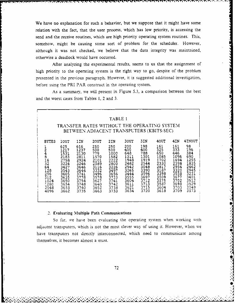
We have no explanation for such a behavior, but we suppose that it might have some
relation with the fact, that the user process, which has low priority, is accessing the
send and the receive routines, which are high priority operating system routines. This,
somehow, might be causing some sort of problem for the scheduler. However,
although it was not checked, we believe that the data integrity was maintained,
otherwise a deadlock would have occurred.
After analyzing the experimental results, seems to us that the assignment of
high priority to the operating system is the right way to go, despite of the problem
presented in the previous paragraph. However, it is suggested additional investigation,
before using the PRI PAR construct in the operating system.
As a summary, we will present in Figure 5.3, a comparison between the best
and the worst cases from Tables 1, 2 and 3.
TABLE 1
TRANSFER RATES WITHOUT THE OPERATING SYSTEMBETWEEN ADJACENT TRANSPUTERS (KBITSISEC)
BYTES 1OUT fiN 2OUT 21N 3OUT 31N 4OUT 41N 4INOUT1 625 616 250 250 200 198 161 161 982 1217 1237 500 500 400 400 325 333 1964 1531 2130 779 1000 648 788 650 646 3848 2183 2811 1570 1582 1311 1301 1085 1096 69016 2758 2924 2101 2222 1948 1919 1702 1694 125532 3224 3246 2589 2800 2482 2544 2330 2398 183564 3427 3646 3116 3226 2942 3048 2817 2954 2462128 3543 3644 3332 3497 3265 3390 3187 3320 2945256 3605 3741 3496 3656 3444 3596 3398 3558 3231512 3635 3778 3578 3733 3555 3697 3509 3677 34011024 3650 3754 3627 3741 3604 3712 3575 3702 35121280 3654 3748 3640 3742 3611 3713 3587 3698 35292048 3658 3740 3652 3738 3621 3715 3604 3703 35494096 3662 3735 3663 3733 3634 3720 3618 3709 3573
2. Evaluating Multiple Path Communications
So far, we have been evaluating the operating system when working with
adjacent transputers, which is not the most clever way of using it. However, when we
have transputers not directly interconnected, which need to communicate among
themselves, it becomes almost a must.
0
72
%I
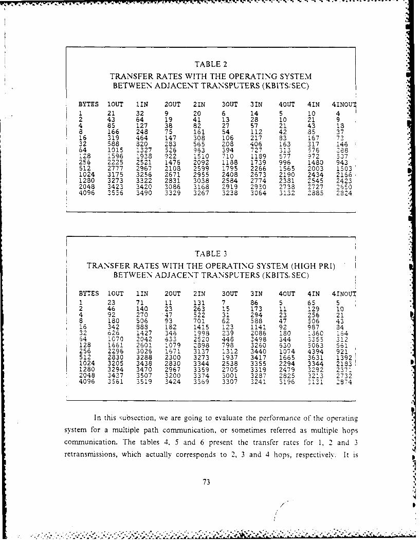
lw-.w rw VV T 'VqdVWYY .P'T ' P0'? NK' Iv R- . -~- ~ ~ WWVJ u uw-
TABLE 2
TRANSFER RATES WITH THE OPERATING SYSTEMBETWEEN ADJACENT TRANSPUTERS (KBITSiSEC)
BYTES 1OUT fIN 2OUT 21N 3OUT 31N 4OUT 41N 41NOUI "
1 21 32 9 20 6 14 5 10 42 43 64 19 41 13 28 10 21 94 85 127 38 82 27 57 21 43 188 166 248 75 161 54 112 42 85 37 i16 319 464 147 308 106 217 83 167 7332 588 820 283 565 208 406 163 317 14664 1015 1327 526 963 394 727 313 576 286128 1596 1938 922 1510 710 1189 577 972 507256 2225 2521 1476 2092 1188 1739 996 1480 943512 2777 2967 2108 2599 1795 2266 1565 2003 1503 1
1024 3175 3256 2671 2955 2408 2673 2190 2434 216611280 3273 3222 2831 3038 2584 2774 2381 2545 24232048 3423 3420 3086 3168 2919 2930 2738 2727 2%504096 3556 3490 3329 3267 3238 3064 3132 2385 2324
TABLE 3
TRANSFER RATES WITH THE OPERATING SYSTEM (HIGH PRI)BETWEEN ADJACENT TRANSPUTERS (KBITS, SEC)
BYTES lOUT I1N 2OUT 21N 3OUT 31N 4OUT 41N 41NOUT1 23 71 11 131 7 86 5 65 52 46 140 23 263 15 173 11 129 104 92 270 47 522 31 294 23 256 218 180 506 93 701 62 588 47 506 4316 342 883 182 1415 123 1141 92 987 8432 626 1427 346 :998 239 2086 180 :360 16464 1070 2042 633 2520 448 3498 344 3355 212128 1661 2601 1079 2898 798 3260 630 5063 561256 2296 3026 1671 3137 :312 3440 1074 4394 921512 2830 3288 2300 3273 1937 3417 1665 3631 13921024 3205 3438 2830 3344 2538 3355 2294 3344 2183:1280 3294 3470 2967 3359 2705 3319 2479 3292 23712048 3437 3507 3200 3374 3001 3287 2825 3213 27324096 3561 2519 3424 3369 3307 3241 3196 3131 2874
In this subsection, we are going to evaluate the performance of the operating
system for a multiple path communication, or sometimes referred as multiple hops
communication. The tables 4, 5 and 6 present the transfer rates for 1, 2 and 3
retransrmissions, which actually corresponds to 2, 3 and 4 hops, respectively. It is
73
/
.......
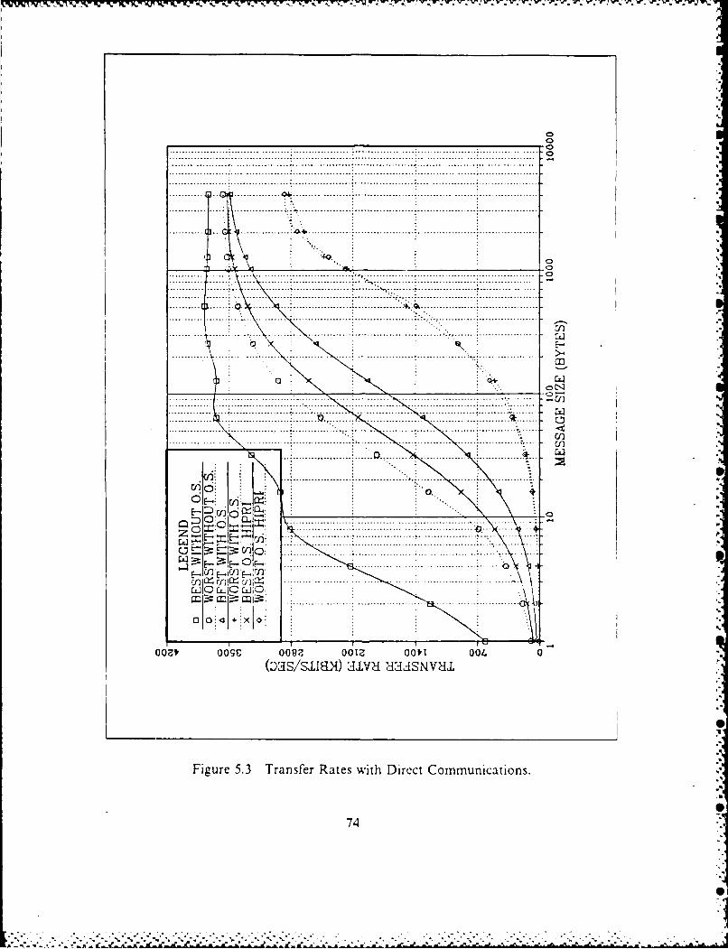
K. .......... ..... .. .. .. .............. - ... .................................... .. .. . .. . .. .. . .. . .. .. . .. .. . .. . .. . .. . . .. . .. . .. .. . .. 0.. ........... .... ... .. . .. . .. .. . .. . .. .. . .. . .. .. . ... .. . .. .. . .. . .. .. . .. . .. ..... ... ..... ........... ..... .............................. .. ........... o............ ........ ............ .......................... .. .... 0...........~~~~~~ 19 Cw ...... .bt.................. . ..... .. ... ...
.. .. .. .. ..
.. . . . .. . . ..... . . . .
.... ... .. .. . ..... ... .. ... ... .... ... ... .. ... .... .. ... ... ... .... . . ... ... ... ...
.... .. .. .. .... ... ... ... .... ... ... . ..... ... ... ... .... ... ... ...
.... ... .. ... .. . . ... .. ... .... ... ... ... ... ... ... : ... ... .... ... ... ... ... ... ... ... ... ...
.......... _ _ _ _ ....... _ .0.. . . . . . . . . . . . . . .. . . . . . . . . . . . . . . . . . . . . . . . . . . .
.. .. . . . . .. . . . . . . ... . . . . . . . ... . . . . . . ...*. i . . . .. . . . . . . . .. . . . . . ..... ... .. . ... . .. ... ... ... ... .... ... .... ... .... ... ...
.......... .......... .......... .(Dass~ua) ZLWI II.1NCa
. - ~ S S 2 KJ P. J~ . ... ... .. . ... . .. . . ... ... .. . -. ..... .... .. . ... ~ ....... ... . . ~ A S A . - . ~ .
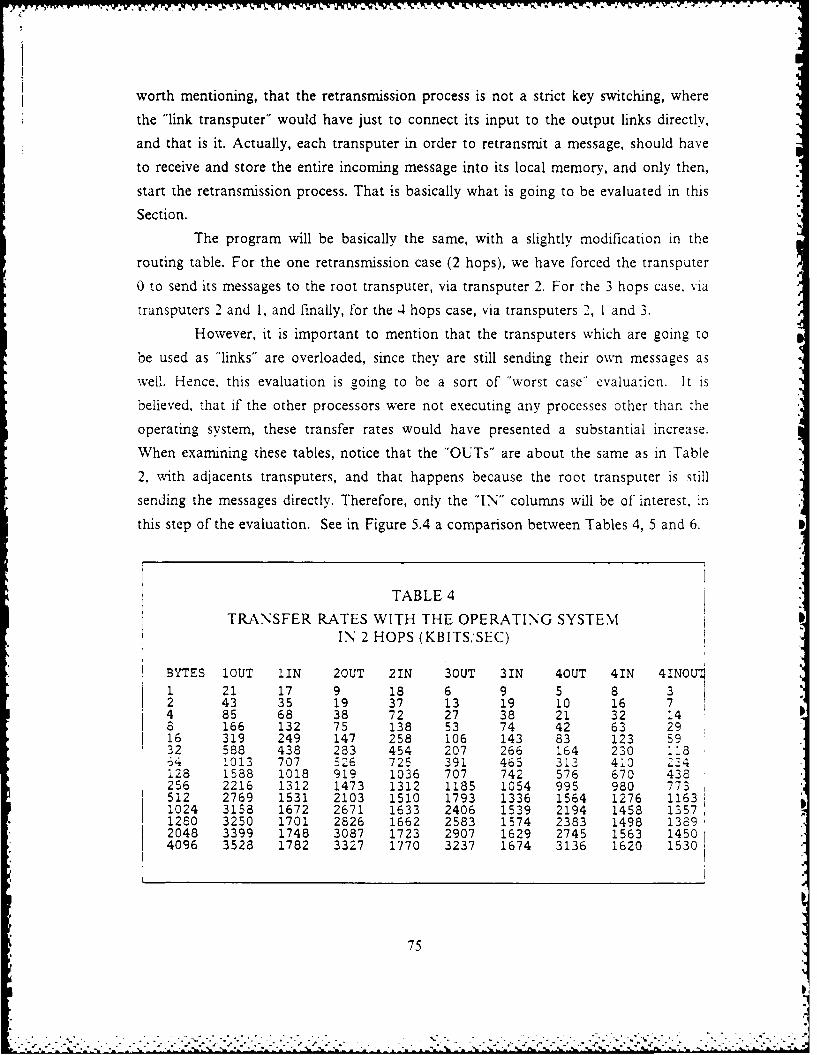
worth mentioning, that the retransmission process is not a strict key switching, where
the "link transputer" would have just to connect its input to the output links directly,
and that is it. Actually, each transputer in order to retransmit a message, should have
to receive and store the entire incoming message into its local memory, and only then,
start the retransmission process. That is basically what is going to be evaluated in this
Section.
The program will be basically the same, with a slightly modification in the
routing table. For the one retransmission case (2 hops), we have forced the transputer
0 to send its messages to the root transputer, via transputer 2. For the 3 hops case. via
transputers 2 and 1, and finally, for the .4 hops case, via transputers 2, 1 and 3.
However, it is important to mention that the transputers which are going to
be used as "links" are overloaded, since they are still sending their own messages as
well. Hence, this evaluation is going to be a sort of "worst case" evaluation. It is
believed, that if the other processors were not executing any processes other than the
operating system, these transfer rates would have presented a substantial increase.
When examining these tables, notice that the "OUTs" are about the same as in Table
2, with adjacents transputers, and that happens because the root transputer is still
sending the messages directly. Therefore, only the "IN" columns will be of interest, in
this step of the evaluation. See in Figure 5.4 a comparison between Tables 4, 5 and 6.
TABLE 4
TRANSFER RATES WITH THE OPERATING SYSTEMIN 2 HOPS (KBITS,'SEC)
BYTES 1OUT 1IN 20UT 21N 30UT 31N 4OUT 41N 4INOU
1 21 17 9 18 6 9 5 8 32 43 35 19 37 13 19 10 16 74 85 68 38 72 27 38 21 32 148 166 132 75 138 53 74 42 63 2916 319 249 147 258 106 143 83 123 5932 588 438 283 454 207 266 164 230 l1l4 013 707 526 725 391 465 313 410 Z34128 1588 1018 919 1036 707 742 576 670 438256 2216 1312 1473 1312 1185 1054 995 980 773512 2769 1531 2103 1510 1793 1336 1564 1276 11631024 3158 1672 2671 1633 2406 1539 2194 1458 13571280 3250 1701 2826 1662 2583 1574 2383 1498 13892048 3399 1748 3087 1723 2907 1629 2745 1563 145014096 3528 1782 3327 1770 3237 1674 3136 1620 1530
75
/ - '. . . . ..- .2 ..
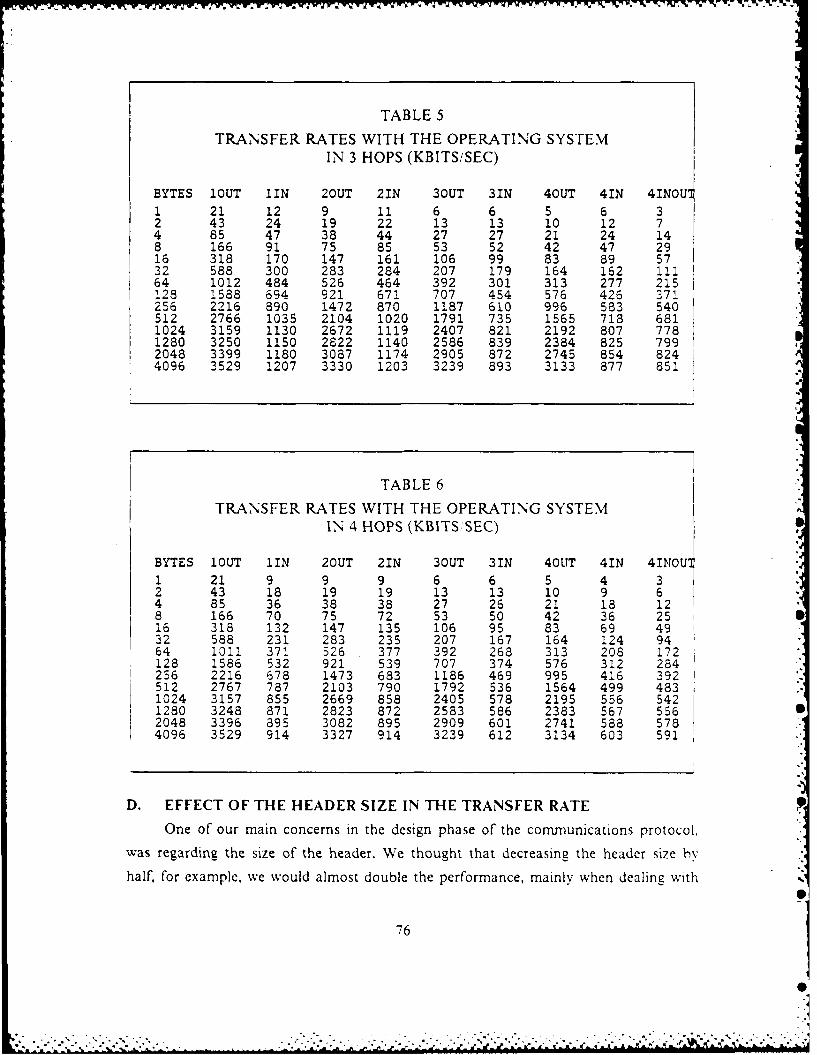
TABLE 5
TRANSFER RATES WITH THE OPERATING SYSTEMIN 3 HOPS (KBITS/SEC)
BYTES lOUT 1IN 2OUT 21N 3OUT 31N 4OUT 41N 4INOUI1 21 12 9 11 6 6 5 6 32 43 24 19 22 13 13 10 12 74 85 47 38 44 27 27 21 24 148 166 91 75 85 53 52 42 47 2916 318 170 147 161 106 99 83 89 5732 588 300 283 284 207 179 164 162 il164 1012 484 526 464 392 301 313 277 215128 1588 694 921 671 707 454 576 426 371256 2216 890 1472 870 1187 610 996 583 540512 2766 1035 2104 1020 1791 735 1565 718 6811024 3159 1130 2672 1119 2407 821 2192 807 7781280 3250 1150 2822 1140 2586 839 2384 825 7992048 3399 1180 3087 1174 2905 872 2745 854 8244096 3529 1207 3330 1203 3239 893 3133 877 851
TABLE 6TRANSFER RATES WITH THE OPERATING SYSTEM
IN 4 HOPS (KBITS, SEC)
BYTES lOUT fIN 2OUT 21N 3OUT 31N 4OUT 41N 4INOUI1 21 9 9 9 6 6 5 4 32 43 18 19 19 13 13 10 9 64 85 36 38 38 27 26 21 18 128 166 70 75 72 53 50 42 36 2516 318 132 147 135 106 95 83 69 4932 588 231 283 235 207 167 164 124 9464 1011 371 526 377 392 268 313 208 172128 1586 532 921 539 707 374 576 312 284256 2216 678 1473 683 1186 469 995 416 392512 2767 787 2103 790 1792 536 1564 499 4831024 3157 855 2669 858 2405 578 2195 556 5421280 3248 871 2823 872 2583 586 2383 567 5562048 3396 895 3082 895 2909 601 2741 588 5784096 3529 914 3327 914 3239 612 3134 603 591
D. EFFECT OF THE HEADER SIZE IN THE TRANSFER RATE
One of our main concerns in the design phase of the communications protocol,
was regarding the size of the header. We thought that decreasing the header size by
half, for example, we would almost double the performance, mainly when dealing with
76
" "" """ " . .- . ... .,7"." 7 ," -," ,. _'~ .,',''' ,, ,' € 1 - ,
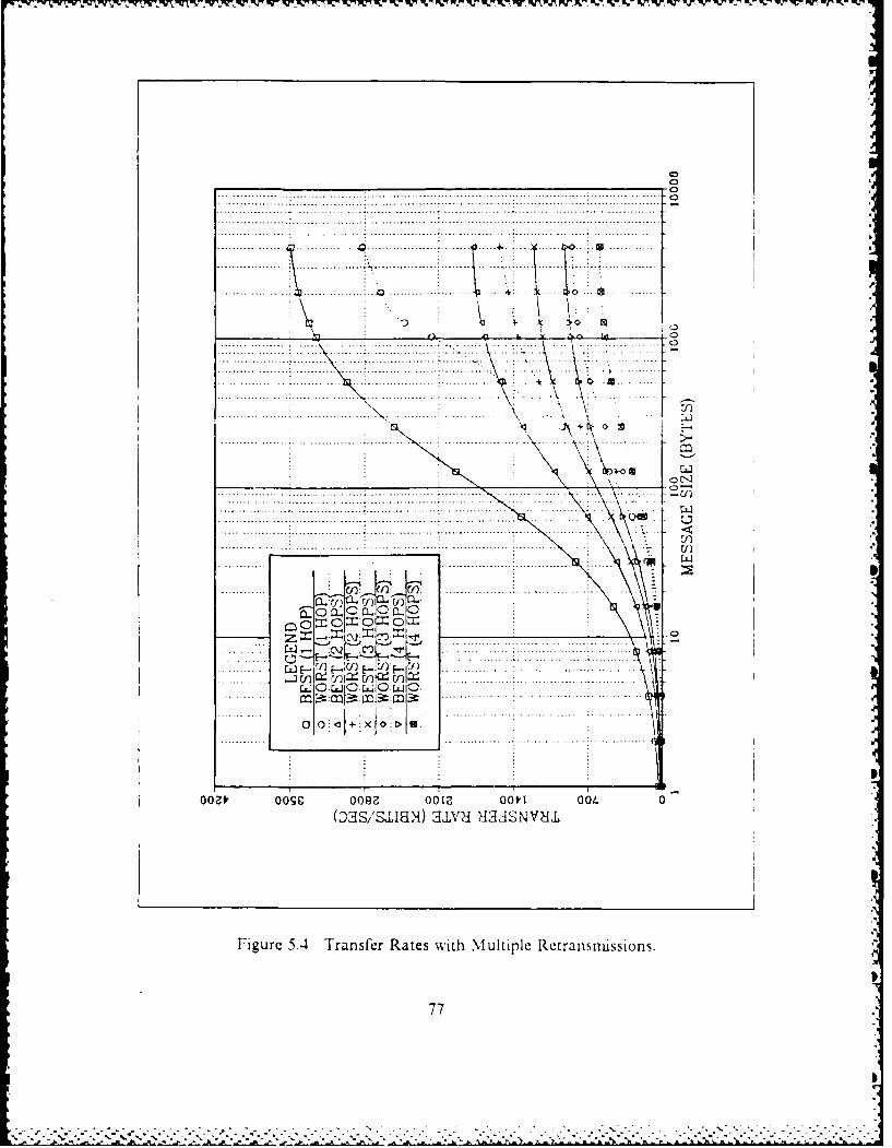
... ... . . . .. . .. ... ... .. ... .. ... .
.. .. . .. ... ..:. .. ... ... :.. .. . .. .. ... .. .... .. .
... .. .. . . .
... ~ ~ ~ ~ \ ...... .......
... ... .. ... ..... ... ... ... ..... ~ ........ ..... ... ... ........
..... .r.. .. .. ....
.o~ .~ ........ ..... .. ' O. ...... 0
U I
.- - - - - - - --.. . .. . . . .. . .. . .. ..
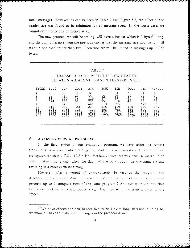
small messages. However, as can be seen in Table 7 and Figure 5.5, the effect of the
header size was found to be minimum for all message sizes. In the worst case, we
cannot even notice any difference at all.
The new protocol we will be testing, will have a header which is 3 bytes 1 7 long,
and the only difference from the previous one, is that the message size information will
* take up one byte, rather than two. Therefore, we will be limited to messages up to 255
bytes.
TABLE
TRANSFER RATES WITH THE NEW HEADERBETWEEN ADJACENT TPRANSPUTERS (KBITS SEC)
BYTES !OUT 1.N 2OUT 2IN 2OUT 31N 40UT 41N 47:NOUT
1 22 28 14 5 42 44 76 22 64 14 29 10 224 89 i51 56 129 27 59 21 45 193 174 293 92 251 55 116 43 38 3816 32 40 179 469 i10 225 86 172 7632 613 939 341 321 25 419 170 330 15164 1051 1486 626 1329 406 748 324 590 297
1 128 1634 2092 1106 1913 732 1211 597 1051 527255 2266 2648 1697 2456 1216 1763 1026 1518 957
E. A CONTROVERSIAL PROBLEM
In the first version of our evaluation program, we were using the remote
transputers, which are T414 (15 Mhz), to send the svnchronization .lags to "he root
transputer. which is a T-41-; 1 12.5 M iz. We had chosen this way because %ve would be
able to start timing onli after the flag had passed through the operating system,
resulting in a more accurate timing.
However, after a period of approximate!.v 10 seconds the rnrogram vas
*aeaui!ccke :n i :anuorn \tate. ma oear .n :nmd 'hat "vtdin this tr:inc..vc .ere i'tc to
perform up to 9 compiete runs oi the same program Another symptom was that
before deadlocking, we could notice a very bh increase in the trans cr rates of the
"INs".
17We have chosen the new header size to be 3 bytes long, because in doing so,we wouldnt have to make major changes in the protocol design.
€.g 78
. .... .. ...... •.. . .. .• .... . . ., , -. . , .-. r.. , ..,
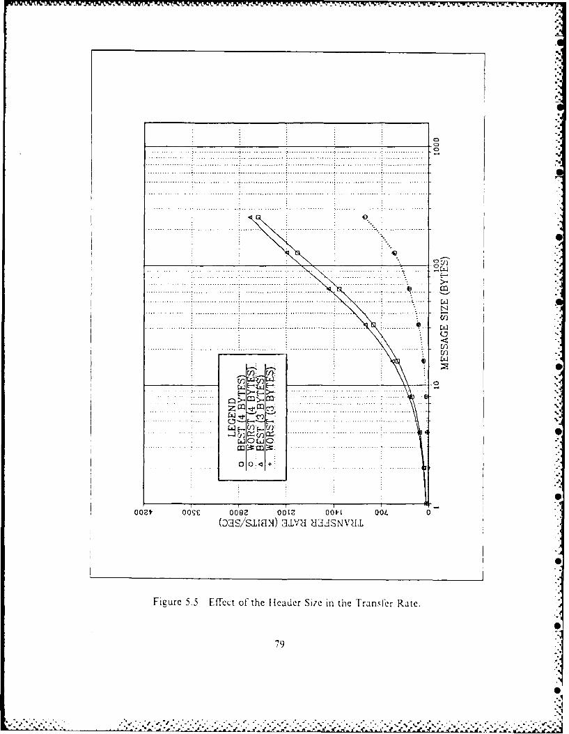
. ........ ..... ... . .. ....... ... ... .... ... . . ... ... . . ... ...
. . . . . . . . . . . . . . . . . . . . .... ... ... .... .. ... . .
.. .. .. ... .. .. . . .. ... . .. . ... .. . .. .. .. . . . . . . . ._ _ _ ._ _ _ ....... ....... .. . . .* . ..0.. . . . . . . . . .
.... ......... . ...........
... . . . . . . .. . . .. .. .. .. .. ..... .. . . .. ... .. ... ... . . ..
.... .. .... ... .. .... ... .. .
.. . .. . . ... . . ... .... ... .. .. ... . . . . . .. ... . . ... . . ... .... .-- . ... ... ... ...
..... . .. ..
.... ... . . . . ... ... .. ... .... .. ...7'
.. .... ... ... ... .. .. ... .. ... ...
... .. .. ... .. .. .. .. .. .. .... .. .. .. .. . .... .. .. ... .. ..
.... .. .... ... .... .. .. .. .. ..... ...... ...... .... ... ............ s L 1~ '1 ...... .... ..............
.... . . .. .. .. . . ... .. ... ....... ... ... . U
Figue 55 Efectof te haderSiz in he rans~r ate
U)- CO79 W
.... ..... ....
....... .... ..- .. ...

The reasons for such a behavior are still unknown, but we found it would bei useful to pass this information, since it may happen again, in some other experiment.
-s
SI
'I.
VV
4.
p
80
p
IS& 2<~.~-~ - - - ... - - - .
------------------ U. ka.a r. a A A -a- S a. a. -a. -S -

VI. USING THE OPERATING SYSTEM
A. INTRODUCTION
This Chapter will introduce the operating system under the user's point of view.
Our system is intended to be used in any transputer network, but when dealing with
very small networks, up to 5 transputers. where we can always -ind :i direct
communication path between them, it may be a better choice not using the 'vhoie
operating system, but just its library routines. mainly when deaiing with small messages
and when efficiencv is a critical issue. However, in all other cases we strongly suggest
Its use, so that the debugging capability of the iistributed system wil be extremely
enhanced. as .vell is -he case oi prograrnming.
B. THE REQUIRED PROGRAM STRUCTURE
The very first steps are basically zhe same for programs with or xithout the
operating system, and they are:
I. Divide the entire program into modules, which can be run in separateprocessors. Ultimately, these modules will become SCs to be placed in ourconfiguration.
2. Specify the interfaces between modules (or SCs) and make a sketch of thedesired configuration.
Now it is time to change a littie bit the structure of the TDS program, as
presented in Chapter ii.
The new structure is the oane presented in Figure 6.1, where some comments are
required or a boetter understanding.
As one can see, what we need to do is to create a filed fold containing either the
root or the remote operating system source code, 18 in each of the SCs. and run the
user process in parallel with the operating system. As discussed in the previous
Clirtcr. 'he P'( P\R construct \hould 'be more effcient. but we sug-est -o ,ic.iop
the entire program .xith no priority assignments, leaving them for the very end.
Another peculiarity is the new parameters list which must be passed in the
configuration part. The channels parameters have been extensively discussed in
Chapter I. when we were talking about configuration, so that at this time, we will skip
"SThey are contained in the files ROOT OS.TDS and REMOTE OS.TDSrespectively.
81
[,,, -'.'" ' ". " ' -' ' " " ' " €" " .' ,"" -, . . "% . - . ".*' ..- . .- . - . - - . - - . "r , -. -. -. ._. . .'- -. . ..-. . -
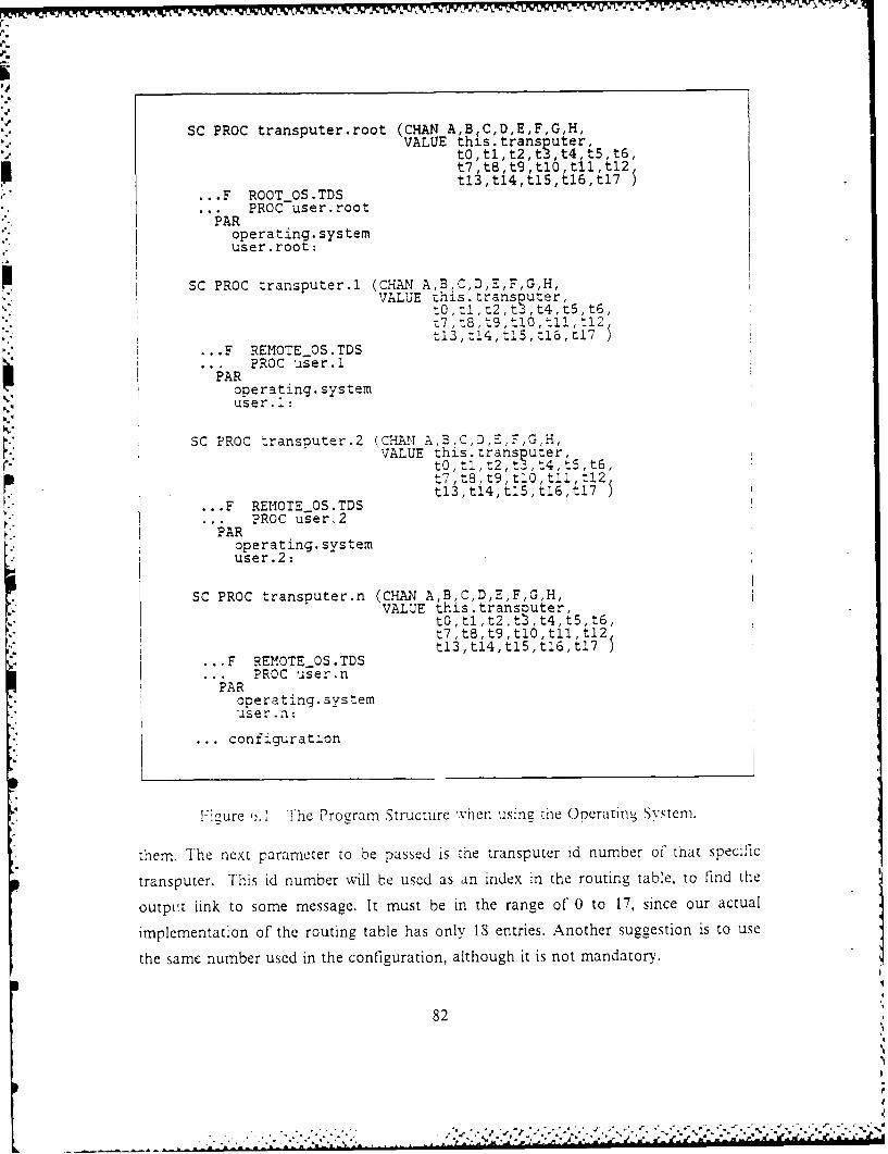
SC PROC transputer.root (CHAN A, B C,D,E,F,G,H,VALUE this.transputer,
tO,tl,t2,t3 ,t4,t5,t6,t7 ,t8 ,t9 ,tlO ,tl , t12t13,t14,t15,t16,t17
* F ROOTOS.TDS.. PROC user.root
PARoperating. systemuser. root:
P SC PROC transputer.1 (CHAN A,B,C,D,E,F,G,H,VALUE zhis crans~uter,
-7t~9,tlO,tll '12)t13,t!4,tJ.3,t16,:J.7
* F REMOTEOS.TDS?ROC user.1I PA~operating. system
user..:
SC PROC transouter.2 (CHANA',BC,D,E,F,G,H,
* F REMOTEOS.TDSPROC usger.2
operating. systemuser .2:
SC PROC transputer.n (CHAN A,B,C,D,E,F,G,H,VALUE this transiouter,
tO,tl,t2,t ,t4,t5,t6,t7,t8,t9,tlO tll t12t13,t14,tJ5,tJ.6,t.7
* F REMOTEOS5.TDSPROC user.n
PARopera ting.systemU e r . nl
.. confi.guration
F icure 6. The PormStructure %vhen iiii he Oneratin- Sx'tem.
them. The next parameter to be passed is the transputer id number of that specific
transputer. This id number will be used as an index in the routing table, to Find the
output link to some message. It must be in the range of 0 to 17, since our actual
implementation of the routing table has only 1S entries. Another suggestion is to use
the same number used in the configuration, although it is not mandatory.
82
W- e- l. r *-t
Finally, the last 18 parameters are the routing table itself, which was already
extensively discussed in a previous Section in Chapter IV. The reason we are passingvalue by value, is just because OCCAMI does not support TABLE data type as a
parameter in the configuration. It is believed that this problem has been overcome in
OCCAM2.
The user "cannot" change the names of the parameters this.transputer and tO up
to t17, since they will be passed as predefined global constants to the Operating
System. These names must be the same for all SCs in the entire program.
C. PROGRAMMING WITH THE OPERATING SYSTEMThe art of programming a distributed system is usually done by lead
programmers, with a great knowledge of the architecture they are working with.
However, in our case, with the aid of the operating system, this task will be so much
simpified. that it will be possibie to an applications programmer to carry out ihis job.
However, as in any operating system, there are some peculiarities, which must be
known by the user, before he starts to use it, and in our case they are the following:* Whenever we want to communicate with external transputers we must use the
send" or "receive" routines. We also maintain in our Library a series of I, 0routines and some utilities, which make use of the send routine and must beused only if we want to have some kind of output to the screen. Therefore,when using these library routines, we must always have the root transputer asour final destination.
* The user must have a complete knowledge, of the available library routines forthe root, and for a remote transputer as well. We have tried to keep the samenames for the procedures in both libraries, just adding a "rem" in front of theoriginal name, if it was to be used in a remote transputer. The only exceptionwas the "write.string". which was taken out from the remote libra'v, since the"send" routine performs the same task, with even some more enhancements.
* If for some reason, none of the library routines fits our needs, we can stillremotely access the screen, by using the "send" with the special channel "40" orscm.
* In the actual implementation, the valid channel ids are multiples of 10. startingf'rom 50 up to 240.
* It is very important to keep in mind that for every "send" operation, must exista matched "receive", with the same channel id number, and in the samedestination transputer of the "send".
As one can see, there is no difficulty in programming with the operating system.
In very few words, what needs to be done, is nothing else than a standard uniprocessor
83
I:
program, and wherever we need some sort of external communication, either to the
screen, or to any other transputer, we just have to follow the previous rules. As an
example, we will provide in Appendix F, a complete listing of the evaluation program,
which was running under the Operating System. In this program we make very little
use of the various library routines available for remote transputers, but the main idea is
just to show the overall structure of a program running under the Operating System.
D. ADVANTAGES OF THE OPERATING SYSTEM
We will now provide a list, with some of the main benefits, originated from the
use of this operating system:
1) We can have as many as needed "send" or "receive" calls inside a paralleiconstruct. The various "send" could be even for the same transputer, in whichcase, the operating system would take care of multiplexing them. through thecorrect output link. The only requirement is that all the channel ids in each ofthe send inside a parallel construct must be different.
2) Now we have the capability of debugging remote transputers. For example. wecan send a unique flag to the screen when entering or exiting ever. procedurerunning in some remote transputer, so that we could obtain a complete traceof our program, and even determine where the system was deadlocking, if thatwas the case.
3) Thanks to the remote dump routine we can now dump the entire memory ofany transputer in the network.
4) With the remote 1,0 routines, we have got formatting capability, so that wecould have, for example, transputer 1 using the upper left part of the screen,transputer #2 using the middle part, transputer #3 the lower right part, and soforth.
E. CUSTOMIZING THE OPERATING SYSTEM
This Section describes which set up must be performed, prior to the use of this
operating system with some user program.
There is a fold called "Operating System Global Declarations", which is the only
place, where the user should perform any sort of change in the O.S. file. However,
there are some declarations and definitions in there, which just need to be modified for
maintenance purposes, done by qualified people.
In most cases, the only definition we will need to change is the "max.block.size",
which specifies the size, in bytes, of the lengthiest message to be accepted in that
network.
84
2. 2. .r

-W~~ .W 7'r WV w-7 j WV Irv W-7 - - ,-V,
VII. CONCLUSIONS AND RECOMMENDATIONS
A. CONCLUSIONS
This thesis is a first effort in developing an Operating System for a distributedsystem of transputers. It was built from three basic modules, namely, Input Handler,
Output Handler and Screen Handler. which were implemented under severe efficiency
requirements.
In order to achieve this basic requirement, we had to avoid moving data insideour system, as much as we could. A close look at the code will confirm, that most ofthe processing time is spent in exchanging flags among the different modules inside the
operating system. Even the flags were checked for eilcienc., in other words, the typeof flag we are using is proved to be the fastest one in that regard. As the reader can
notice, most of the flags and 1,0 are implemented with the BYTE.SLICE construct,which has been proved to be the fastest construct available in the transputer [Ref. 91.Only in the alternate construct we keep the standard OCCAM 10 channels, becausethe "ALT" does not accept the BYTE.SLICE as a valid guard channel.
Now, as'we may recall from Chapter V, the performance figures of the operatingsystem, demonstrates that it is quite efficient, mainly for messages bigger than 2048bytes. At this size for example, we have losses ranging from 8% up to 25%, depending
on the number of channels, which are transmitting and receiving in parallel.' 9 The lastvalue was obtained when the 4 channels were transmitting and receiving in parallel.
As far as debugging goes, the operating system was very successful, in the sensethat it brought up a new perspective in this field, for a distributed system oftransputers. Although we realize that it is still far from being ideal, we should agree
that it provides the user with some capabilities, which were not easily achieved up tonow.
The other main goal *o be achieved by this thesis, is regarding the ease oiprogramming a distributed system of transputers. Now, anyone would be able to very.quickly, make a program to be run in a very large transputer network.
t 9This figures can be increased, mainly when dealing with smaller messages, if wedecide to use the operating system in high priority, as depicted in Chapter V (Table 3).
85
........................

Returning to the efficiency issue, which is one of the major concerns in real time,
we strongly believe that if the present trend of increasing transmission speed continues,
we will be reaching a point where no more shared memory will be needed, since the
link speeds will be sufficient high, to allow the transmission of the global shared data
to all users of it. Let us put some numbers in this previous assumption. Assuming thatthe new family of transputers, the T-800's, will really support a truly 30 MBits/sec for
the link transmission speed, we will be able to achieve with our basic operating system,after 4 retransmissions, and also considering the worst case (4INOUT), rates of the
order of 5 MBits,/sec, which is a fairly high rate.Two conclusions can arise from the preliminary results. First, a real time
operating system for a network of transputers is feasible and highly recommended.Second, the shared memory architecture seems to be no longer the preferablearchitecture for sharing global data, since we are going to be able to achieve
comparable results, without the disadvantages of having shared memory, like 'or
example. the system bus constituting a single point of failure.
Therefore, the transputer appears to be an attractive architecture for
implementing real time applications, where the reliability is a fundamental issue.
B. RECOMMENDED FOLLOW-ON WORK
As stated in Chapter 1, this thesis is a first approach to a basic operating system
for a network of transputers, and it is our hope that it serves as a firm foundation for
future and more enhanced implementations.
As this thesis was being developed, many new ideas were brought up, and in this
Section we will try to give some suggestions for future enhancements in the system:
• Conversion of all programs used in this thesis to OCCAM2. It is alsoimportant, to reevaluate this new version of the operating system.
* Implementation of some filer routines which would allow one to open, close,read and write to VMS files. However, it is believed that OCCAM2 providesalready this capability.
* Creation of one more reserved channel in the Operating System. which couldhandle inputs from the keyboard to remote transputers, with a inimuminterference in the process running in the root transputer. The suggestion is tomake up a simple protocol for entering data from the keyboard, for example,always entering with the destination transputer id# first, followed by a carriagereturn, and only then, we should enter with the actual input data. The next stepshould be to change the procedure "read", which is inside the terminal driver,and insert a check for the transputer id#. If after checking, it was found to befor a remote transputer, we should send the incoming message directly to the
86
remote transputer, through a new reserved channel, in such a way, that theremote transputer would be able to recognize that the message was carryingsome keyboard input data.
* Implementation of an adaptive routing to replace the present one, which isstatic. This feature could be further extended, in order to generate a completefault tolerant system. OCCAM2 provides some built-in procedures like"OutputorFail", InputorFail" and "Reinitialise", which might be very helpful insolving this problem [Ref. 11].
* Construction of a more powerful set of Library Routines for the root andremote transputers, e.g. concatenation,....
* Make the Operating System resident in the transputers, in other words, whenwe turn the power on, it should be automatically loaded into ail transputers. Toaccomplish this step we would need to change the loader program. whichresides in the EPROM of the BOO board.
* Construction of a more powerful debugger. However, it is not imperative, inour understanding, to make a debugger with multiprocessor capabiiity. since wecan always map our program to run into a single transputer. In order toimplement a debugger, we would have to make it resident in the upper part ofmemory, and we would also need to have some kind of deassembler, in order tocorrectly place the breakpoints inside the code.
* Enhancement of the Terminal Driver by changing its ,10 handling. Presently. itis implemented by standard OCCAM I;O channels, so, the idea is to use theBYTE.SLICE, which is a much faster construct. However, keep in mind in mindthat the single character will have to be handled as a special case, since theBYTE.SLICE only supports byte arrays.
8
; 87
E
-. . . . . . . . . . . . . . . . . . . . . . . . . . . . . . . . . . . . . . . . . . . ..". . '-" " '-'-"'"," '"'". ", - .,,"' " ". , ."- --, .-° -
"' .",='W,',:,W.€

APPENDIX A
OPS GLOBAL DEFINITIONS (GLOBALDEF.OPS)
-- globaldef.ops-- Constant DefinitionsDEF port = 0 --- assigns the RS232 port to the terminalDEF baud = 11: set baud.rate to 9600 bpsDEF nul = 0 --- null ascii valueDEF bell = 7 --- bell ascii valueDEF tab = 9 --- tab ascii value (every 8 col)DEF lf = 10: linefeed ascii valueDEF cr = 13: --- carriage return ascii valueDEF esc = 27: --- escape ascii valueDEF sp = 32: --- space ascii value-- Channel DeclarationsCHAN Parameters AT 0CHAN Screen AT 1CHAN Keyboard AT 2CHAN FileinO AT 3CHAN Fileini AT 4CHAN F.lein2 AT 5
" CHAN Filein3 AT 6CHAN Filein4 AT 7CHAN Filein5 AT 8CHAN Filein6 AT 9CHAN Filein7 AT 10CHAN FileoutO AT 11CHAN Fileoutl AT 12CHAN Fileout2 AT 13CHAN Fileout3 AT 14CHAN Fileout4 AT 15CHAN Fileout5 AT 16CHAN Fileout6 AT 17CHAN Fileout7 AT 18
-- Link DefinitionsDEF link0out = 0DEF linklout = IDEF link2out = 2DEF link3out = 3DEF link0in = 4DEF linklin = 5DEF iink2in =5DEE link3in = 7-- File Handler Control ValuesDEF ClosedOK = -1DEF CloseFile = -2DEF EndBuffer = -3DEF EndFile = -4DEF EndName = -5'EF EndParameterString = -6DEF EndRecord = -7DEF NextRecord = -9DEF 0penedOK = -10DEF OpenForRead = -11DEF OpenForWrite = -12
88
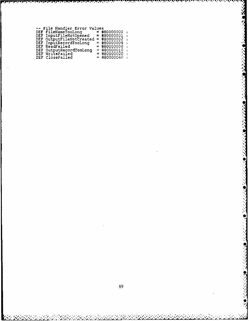
-File Handler Error ValuesDEF FileNameTooLong = #80000000DEF InputFileNotOpened = #80000001DEF Ou tputFileNotCreated = #80000002DEF InputRecordTooLong = #80000004DEF ReadFailed = #80000008DEF OutputRecordTooLong = #80000010DEF WriteFailed = #80000020DEF CloseFa±Jled = #80000040
89S
%p

APPENDIX BTDS GLOBAL DEFINITIONS (GLOBALDEF.TDS)
-- globaldef.tds-- Constant DefinitionsDEF oort = 0 : --- assigns the RS232 port to the terminalDEF Saud =11 --- set baud.rate to 9600 bpsDEF nul = 0 --- null ascii valueDEF bell = 7 : --- bell ascii valueDEF tab = 9 --- tab ascii value (every 8 col)DEF If = 10: --- linefeed ascii valueDEF cr = 13: --- carriage return ascii valueDEF esc = 27: --- escape ascii valueDEF sp = 32: --- space ascii value-- Channel DeclarationsCHAN ScreenCHAN Keyboard
-- Link DefinitionsDEF link0out = 0DEF linklout = IDEF link2out = 2DEF link3out = 3DEF linkOin = 4DEF linklin = 5DEF link2in = 6DEF link3in = 7
90
S
&..A..A.

APPENDIX CTDS LIBRARY ROUTINES WITHOUT OPERATING SYSTEM
(LIBRARY.TDS)lp
* Title: LIBRARY.TDS * Version: 1.0 ** Author: MAURICIO DE MENEZES CORDEIRO * Mod: 0 ** Date: 19/FEB/1987* Programming Langage: OCCAM I *
Compiler: IMS 6-6 0 (VAX/'NS)-* Dr escripton: This program contains some library*
* rotines to be used in any TOS program, when not *usrng the Oerating System. It musi be olaced in *
paralel wiTh the user process and with the global-* definitions for TDS. *
* Mod #: Date: ** Responsible: ** Brief Description:
* Mod ": Date: ** Responsible: ** Brief Description: *
- io routinesPROC dec.to.hex (VALUE integer, VAR string[]) 1I.. ******************** ***** WW %*******
--- DESCRIPTION: It converts an integer number from its *--- decimal representation into the equivalent hexadecimal *--- one. It accepts any valid integer. It returns the *
hexadecimal number stored in a strin2 of 10 bytes long *where the leading zeros are preserved. *It returns the following format: [size]#0000FFFF *USAGE: dec.to.hex(37182,hex.string) _.REMARK: The BYTE[0] of the string carries its length *which is always 9, therefore it could be deleted, but *
--- we decided to-keep it. *
PROC dec.to.hex (VALUE integer. VAR string [.) =VAR first, order.of.digit, digit :VAR numberDEF hex.char = "0123456789ABCDEF" :SE irst := TRUE
Sstring [BYTE 0] : 9string [BYTE] :1 #number := integerorder.of.4igit = 9WHILE inumber > 0) OR (first=TRUE)
igit =number /\ #Fdigit : hex.char [BYTE digit + 11string [BYTE order.of.digit] := digitnumber := number >> 4order.of.digit := order.of.digit - 1first := FA SE
SEQ i = [2 FOR (order.of.digit - 1)string [BYTE i] := '0 :
-- PROC dec.to.ascii (VALUE integer, VAR string [])
91
.4'

--DESCRIPTION: It converts an integer number from its *--- decimal representation into the equivalent ASCII one. It *
accepts any valid integer number. It returns the ASCII *number stored in a string of 12 bytes long, where the *
--number is ri fdifom ae ?ht justified and it has the follo g*
--- 192 42 ---> 1 11 ' '' '' 1 '' If 211 1 9 374 2 *USAGE 1922937 -- >111 11 11 1111191121121191131l71*
--- USAGE: dec.to.ascii(-9873,ascii.string)--- REMARK: The BYTE[0] of the string carries its length *which is always 11, therefore it could be eliminated, but*
we decided to keep it.
PROC dec.to.ascii (VALUE integer, VAR string []) =VAR number :VAR order.of.:git:DEF min.int = - 2147483648
SEQnumber := integerorder.of.dioit : 11string [BYTt 0] : 11
number = ni':.int-- :ak:ng care of the limit caseSEQ
string BYTE I] : -string iTE2j := '2'
string FBYTE 41 14string BYTE 5] 17string hBYTE 6] : 4string BYTE 7 41string [BYTE 3 = 3string BYTE 9] 16string BYTE 11 14string [BYTE 111 1
TRUESE F
number = 05EQ
3 trir 7.[BYTE 1]string BYTE 11] = '0'o rder.ofdigit := 10
numoer < 0
number : numberstring [BYTE 1] :
TRUE --- number > 0stri-ng [BYTE I] :-- -ul/n - ": e c~ "numbe r
WHKE number .nm
.rina 'YTE order.of.digit] := 'number :0) 1''number := (number / 10)order.of.digit := order.of.digit - 1
SEQ i = [2 FOR (order.of.digit - 1)]string [BYTE i] '
PROC hex.to.dec $VALUE strin41h VAR inte er OK)
--- DESCRIPTION: It accepts a hexadecimal representation of *a number and converts it into an integer number. It *
--- expects the byte[O] of the string to carry the size *--- information of that "hex number". *
92
. -. - -.------ .-----------------
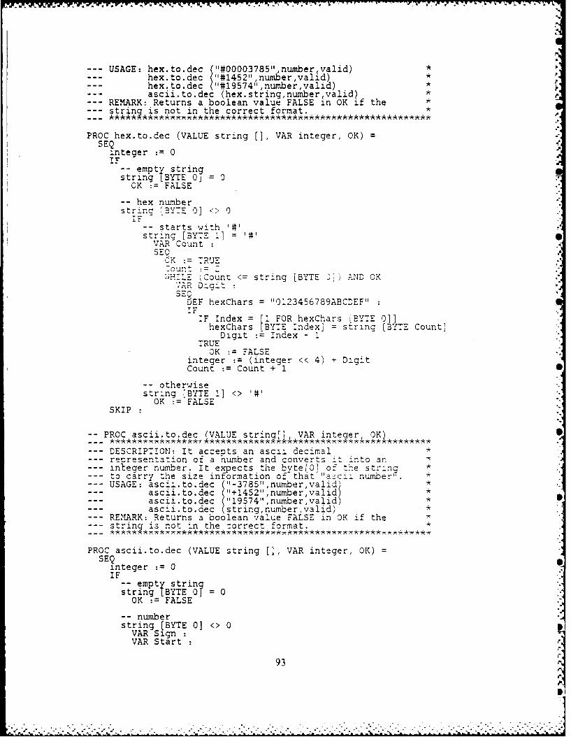
- . a 4 s.*. . . . % - ....% . ,. . - k :. . ,
--- USAGE: hex.to.dec ("#00003785",number~valid) *hex.to.dec ("#1452",number,valid) *hex.to.dec ("#19574",number,valid) *
--- ascii.to.dec (hex.string,number~valid) * r--- REMARK: Returns a boolean value FALSE in OK if the *--- strinl is not in the correct format. *
PROC hex.to.dec (VALUE string [], VAR integer, OK) =SEQ
integer := 0IF
-- empty stringstring LBYTE 0 = 0OK := FALSE
-- hex numberstring [BYTE 0] <> 0IF
-- starts with '#'string [BYTE 1] =41VAR CountSEQ
CK := TRUE-ount :=:- -...E (Count <= string [BYTE ] AND OK"R DigitSEQDEF hexChars = "0123456789ABCDEF"IF
IF Index = [I FOR hexChars [BYTE 0]]hexChars [BYTE Index] = string [BYTE Count]
Digit := Index - ITRUE
OK := FALSEinteger := (integer << 4) + DigitCount := Count + 1
-- otherwisestring [BYTE 1] <> '#'
OK := FALSESKIP
-- PROC ascii.to.dec (VALUE string[], VAR integer, OK)
--- DESCRIPTION: It accepts an ascii decimal *--- re resentation of a humber and converts it into an--- in eger number. It expects the byte[0 1 of the string *
to carry the size information of that "ascii number .--- USAGE: ascii.to.dec ("-3785",number,valid) *--- ascii.to.dec ("+1452",number,valid) *
ascii.to.dec ("19574",number,valid) *ascii.to.dec (stringnumbervalid) *
--- REMARK: Returns a boolean value FALSE in OK if the *--- string is not in the correct format. *
PROC ascii.to.dec (VALUE string [], VAR integer, OK) =SEQ
integer := 0IF
-- empty stringstring [BYTE 01 = 0OK := FALSE
-- numberstring (BYTE 0] <> 0VAR Sign rVAR Start
93
V.

i
VAR LengthSEQ
OK := TRUEIF
-- negativestring [BYTE 1] =SEcm - 1
Start 2Length string (BYTE 0] - 1
-- positivestring [BYTE 1] <>SEign= 1
Start : 1Length := string [BYTE 0]
-- convert to integerSEQ Index = [Start FOR Length]VAR DigitSEQDigit := string [BYTE Index]IF
(10' <= Dicit) AND (Digit <= 19')integer (integer " 10) + (Digit - '0')
TRUEOK := FALSE
integer := integer * SignSKIP
-- PROC write.string (VALUE t
DESCRIPTION: Writes a given string to the screen, in a *byte by byte fashion. It requires that the string which *is a byte array, provides the size of the string in its *byte [0, otherwise we will get unpredictable results. We *are limited to strings up to 255 characters. For bigger *byte arrays or for partial printing use "send.string . *USAGE: write.string ("Hello,)REMARK: It does not provide an automatic crlf. *
PROC write.string (VALUE string[]) =
EO i = [I FOR strinc[BYTE 0]]
-creen string[BYTE i]SKIP:
-- PROC write.string.fast (VALUE strin
--- DESCRIPTION: This orocedure works just in TDS and speeds *--- up things since the whole block is scheduled by CPU just *
-- nce , unlikely in the PROC write.string where each byte *is individualiy scheduled. However the terminal driverroutine MUST BE chanced prior to the use of this routine.-
-- USAGE: write.strinq.fast (string) *
PROC write.string.fast (VALUE string[])=SEQ
BYTE.SLICE.OUTPUT (Screen,string,l,string[JYTE 0]):
-PROC write.number (VALUE itgr
--- DESCRIPTION: This PROC outputs a signed integer value to *
94
Z. 121
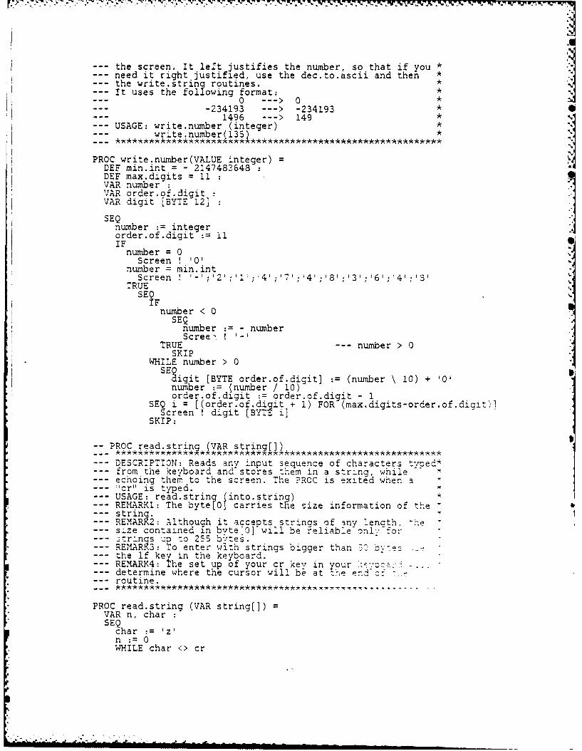
--- the screen. It left justifies the number, so that if you *--- need it right justified, use the dec.to.ascii and then --- the write.string routines.--- It uses the following format: *-- 0 --- > 0 1.... -234193 --- > -234193 40--- 1496 ---> 149 *--- USAGE: write.number (integer) *
write.number(135) *
PROC write.number(VALUE integer) =DEF min.int = - 2147483648DEF max.digits = 11 :VAR numberVAR order.of.digitVAR digit [BYTE 12]SEQ
number := integerorder.of.digit := 11IF
number = 0Screen ! '0'
number = min.intScreen! '-';'2';'I';'4';' ;'4''8';'3';'6';4';S'
TRUESE TF
number < 0SEQnumber : - numberScree, !
TRUE --- number > 0SKIP
WHILE number > 0SEigit [BYTE order.of.digit] := (number \ 10) + '0'
number := number / 10)order.of.digit := order.of.digit - 1
SEc i = [(order.of.diqit + 1) FOR (max.digits-order.of.digit)lcreen !digit [BYTE i]
SKIP:
-- PROC read.string (VAR string[])
--- DESCRIPTION: Reads any input sequence of characters typed*.rom the keyboard and stores them in a string, while
echoing them to the screen. "he ?ROC is exited when a"cr" is typed.USAGE: read.string into.string)REMARKi: The byte[O] carries the size information of the
--- string.--- REMARK2: Although it accepts strings of -ny lenath, h--- size contained in bvte[0]^wiJl be reliable only for--- 3tr-nqs up :o 255 by'tes.--- REMARK3: To enter with strings bigger than 3C bytes---- the If key in the keyboard.--- REMARK4: The set up of your cr key in your ',a¢ ybc: ,..--- determine where the cursor will be at trhe endic:--- routine.
PROC read.string (VAR string[]) =VAR n, charSEQ
char := 1z'n := 0WHILE char <> cr
ADft-RISE 5.93 DESIGN IMPLEMENTAT ION AMD EVALUAT ION OF AN OPERATING 21:2SYSTEM FOR A NETNORK OF TRANSPUTERS(U) NAVALPOSTGRADUATE SCHOOL MONTEREY CA M D CORDE IRO
UWNLSIID FG 5/ L
:~ ~~~L4 1:0 U 2 .d
U 2
11L-25IL
MICROCOPY RESOLUTION .TEST 'CHARTANLARI 1%h A
5.0
lob'% % % %
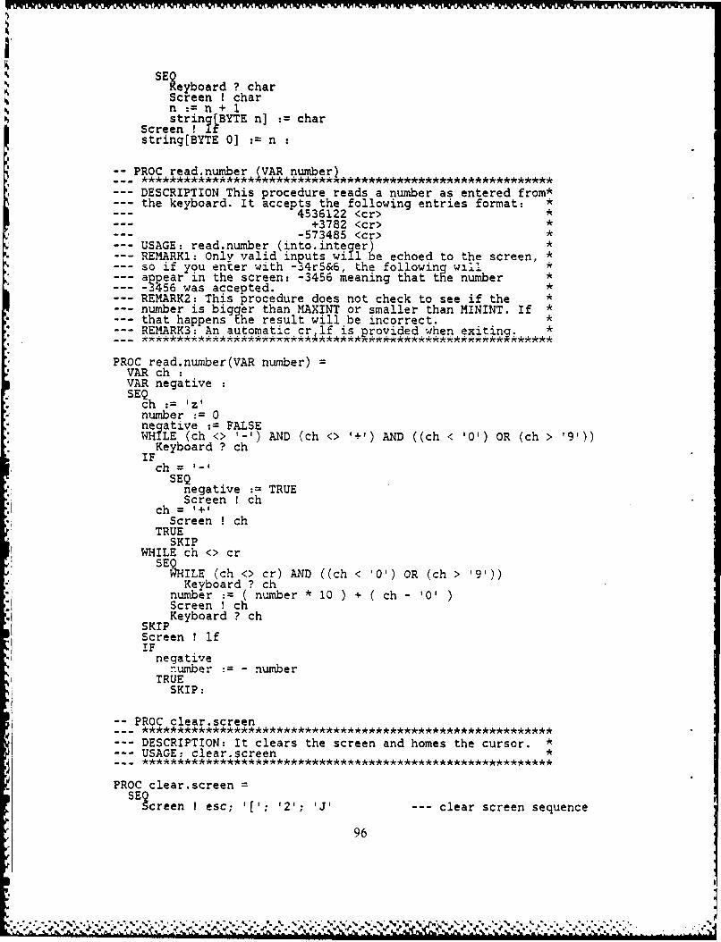
SEeyboard ? char
Screen ! charn:= n + 1string[ BYTE n] . char
Screen 1 Ifstring[BYTE 0] := n
-PROC read.number (VAR number)
DESCRIPTION This procedure reads a number as entered from*--- the keyboard. It accepts the following entries format: *
4536122 <cr> *+3782 <cr> *
--- 573485 <cr> *--- USAGE: read.number (into.integer) *
REMARK1: Only valid inputs will be echoed to the screen, *so if you enter with -34r5&6, the following will *appear in the screen: -3456 meaning that the number *-3456 was accepted. *REMARK2: This procedure does not check to see if the *number is bigger than MAXINT or smaller than MININT. If *that happens the result will be incorrect. *REMARK3: An automatic crlf is provided when exiting. *
PROC read.number(VAR number) =VAR ch :VAR negativeSEQ
ch := 1z'number := 0negative := FALSEWHILE (ch <> '-') AND (ch <> '+') AND ((ch < '0') OR (ch > '91))
Keyboard ? chIFch=SEQnegative := TRUE
Screen ! chch = 1+1
Screen ! chTRUE
SKIPWHILE ch <> crSELILE (ch <> cr) AND ((ch < '0') OR (ch > '9'))
Keyboard ? chnumber :(number *0 )+ (ch 0 )Screen ! ch
SKIP Keyboard ? ch
Screen ! ifIFnegative
number : - numberTRUE
SKIP:
-- PROC clear.screenDESCRIPTION: It clears the screen and homes the cursor. *
--- USAGE: clear.screen *
PROC clear.screen =SE3creen I esc; '['; '2'; 'J' --- clear screen sequence
96
V[
%i -06

WW vu- w
Screen I esc; '['; 'HI: --- home cursor
-POC*Ros.cursor (VALUE line, column)
--- DESCRIPTION: Positions the cursor in a specified line and*--- column. We have used the ANSI escape sequence *---- ESC [Line;Column H.--- USAGE: pos.cursor (8,30) *--- REMARKI: Valid values for line are 0 up to 24 *--- Valid values for column are 0 up to 80 *--- REMARK2: Values out of the above range will cause *--- unpredictable results. *
PROC pos.cursor (VALUE line column) =VAR x [BYTE 2], y [BYTE 21:SET F
(line < 10) AND (line >= 0)SEQy [BYTE 0] : '0'i BYTE 1 line + #30
ine >= 10) AND (line <= 24)SEQy BYTE 0] := (line/10) + 430
[BYTE 1 line 10) + #30TRUE
SKIPIF
(column < 10) AND (column >= 0)SEQ
s [BYTE 0] :'0'x BYTE 1 :=column + #30
(column >= 10) AND (column <= 80)SEQ
x [BYTE 0] := (column/10) + #30x BYTE (column\10 + #30
TRUESKIP
Screen ! esc; [';y BYTE 0] ; y BYTE 11 ;' ;
x [BYTE 0 ; x [BYTE 11 'H
-- PROC new.line (VALUE number)
--- DESCRIPTION: It will skip as many lines as specified in *--- its parameters list. *
USAGE: new.line(4) *RE1MARK: Negative numbers will not ive any new lines. *
PROC new.line (VALUE number) =SE3E? i = [0 FOR number]
5creen ! cr;lfSKIP:
-- PROC spaceVALUE number) * *
--- DESCRIPTION This procedure provides spaces for formatting*a single line. *
USAGE: space(8) *REMARK: This routine does not provide an automatic If *after reachini the end of the line. *
PROC space (VALUE number) =SEQ
97
,. , , .. ,.,,,..... .:. :. ,.,. ,,,

SEQ i = [0 FOR number]Screen I sp
SKIP:
PROC tab QVALUE number)
--- DESCRIPTION This procedure provides tabs for formatting a*single line. Each tab is equivalent to 8 spaces if the *terminal is using the default set up. *USAGE: tab(6)REMARK: This routine does not rovide an automatic lf *after reaching the end of the vine. *
PROC tab (VALUE number) =E' n i = (0 FOR number]
creen tabSKIP:
-- PROC send.strin (CHAN output VALUE strinilstart strin .length)
--- DESCRIPTION: This routine sends a string through a *generic channel output. It also allows to specify a start *
ye, as well as the length of the string to send. *UAGE: send.string (out.channel,"hello", ,3)REMARK1: The above example will actually send the *
--- characters 1,1 and o. *REMARK2: It can be used with the channel Screen as well. *
PROC send.string (CHAN output, VALUE string[],start,string.length)SE
SEQ index = [start FOR string.length]output ! string (BYTE index]
SKIP:
-- PROC receive.string (CHAN input, VAR string[],VALUE start strinj.len~thj
--- DESCRIPTION: This routine receives a string through a *generic channel input. It also allows to specify the *starting byte, as well as the number of bytes to receive *from the incoming string. *USAGE: receive.string (out.channel string.in,3,2) *REMARK1: The above example will actually receive 2 bytes *from the incomingstring starting at byte 2. *
*****w** A, ***k****
PROC receive.string (CHAN input, VAR string[],VALUE start,string.length) =SEEQ index = [start FOR string .length]
:nput ? string [BYTE index?,SKIP:
PROC send VALUE channel.id dest.transDRmessale[],start.bxtesize)
--- DESCRIPTION: It is an operating system routine, and it *is used to communicate between processors. It builds the *header of the message to be sent. It has as parameters *the channel id of the channel which is going to carry on *the communications, the id of the destination transputer *for that message, the start byte and the size of the *message to be transmitted. For every send must exist a *receive for that same channel id in the destination *
98
, . . * ¢ -'.u,_ -,. -.- '....- --_-.- -.. .-.'.,-,. .'-'- '. '-.- . ,-.-,..- -. .,. - -.,'.- " ., ".'.."-'
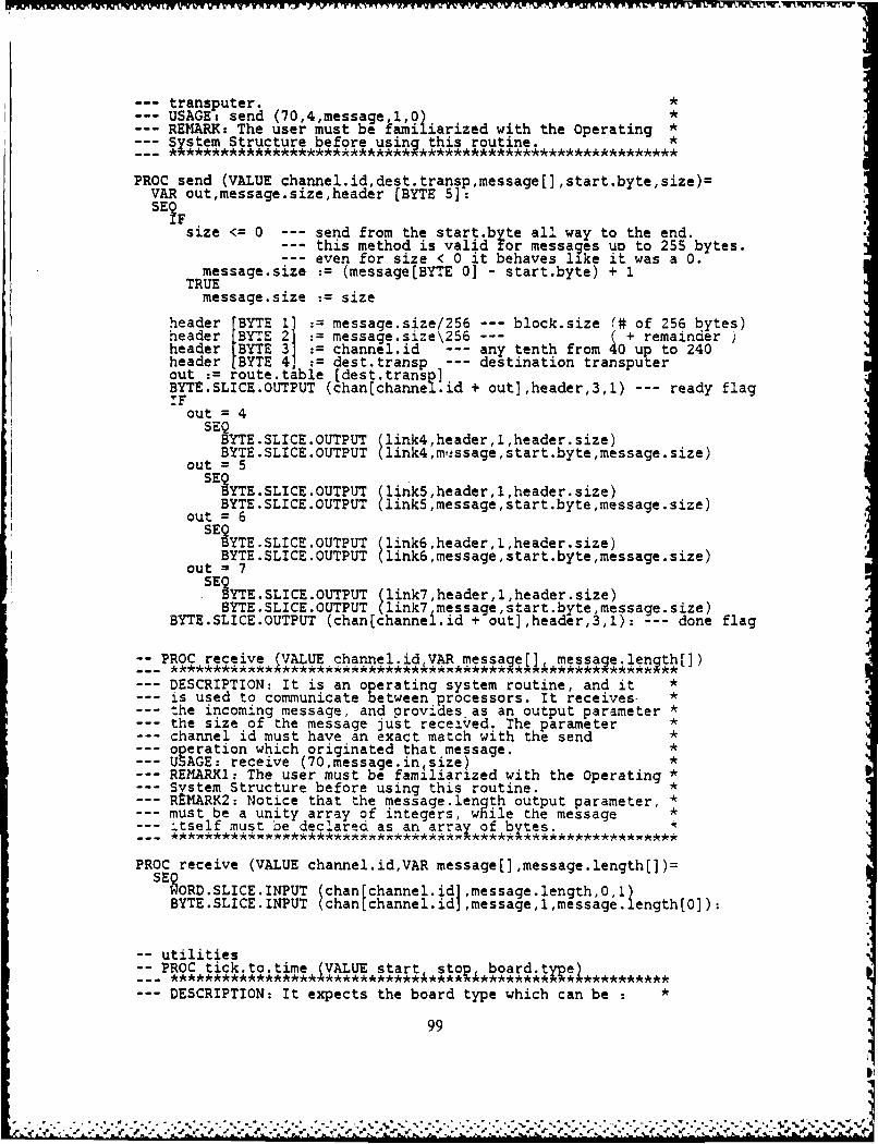
--- transputer.--- USAGE: send (70,4,message,, *REMARK: The user must be familiarized with the Operating *
--- System Structure before using this routine. *
PROC send (VALUE channel.id,dest.transp,message[],start.byte,size)=VAR out,message.size,header [BYTE 5]:SEF
size <= 0 --- send from the start.by te all way to the end.this method is valid for messages uo to 255 bytes.
--- even for size < 0 it behaves like it was a 0.message.size (message[BYTE 0] - start.byte) + 1
TRUEmessage.size size
header [BYTE 1] := message.size/256 --- block.size (# of 256 bytes)header [BYTE 2] message.size\256 --- ( + remainderheader IBYTE 3] : channel.id --- any tenth from 40 up to 240header BYTE 4] dest.transp destination transputerout := route.table (dest.transp]BYTE.SLICE.OUTPUT (chanlchannel.id + out],header,3,1) --- ready flagIFout = 4SEYTE.SLICE.OUTPUT (link4,header,l,header.size)
BYTE.SLICE.OUTPUT link4,mfssage,start.byte,message.size)out = 5
SE YTE.SLICE.OUTPUT (linkS,header,l,header.size)
BYTE.SLICE.OUTPUT (link5,message,start.byte,message.size)out = 6
SEOSYTE.SLICE.OUTPUT (link6,header,lheader.size)BYTE.SLICE.OUTPUT link6,message,start.byte,message.size)
out = 7SE3YTE.SLICE.OUTPUT (link7,header,l,header.size)
BYTE.SLICE.OUTPUT (link7 message,start.byte,message.size)BYTE.SLICE.OUTPUT (chanlchannel.id + out],header,3,1): --- done flag
-- PROC receive XVALUE channel.idVAR message[] nmessale.lenqth[])
--- DESCRIPTION: It is an operating system routine, and it *is used to communicate between processors. It receives *
--- the incoming message, and provides as an output parameter *the size of the message just received. The parameter *
--- channel id must have an exact match with the send *operation which originated that message. *USAGE: receive (70,message.in size)REMARKI: The user must be famlliarized with the Operating *System Structure before using this routine. *REMARK2: Notice that the message. length output parameter, *must be a unity array of integers, while the message *itself must be declared as an arrax of bytes.
PROC receive (VALUE channel.id,VAR message[],message.length[])=SE oRD'SLICE'INPUT chan channel.id message length e
BYTE.SLICE.INPUT chan channel.id1 lssage nt,messge
-- utilities-- PROC tick.to.time (VALUE start stop, board.tye)--- DESCRIPTION: It expects the board type which can be : *
99
%I
board.type = 0 ---. > OPS (VAX VMS) *board.type = 1 --- > B001 (T414:12.5 MHz) *board.type = 2 ---- > B002 *
--- board.type = 31 ---- > B003 (T414:15 MHz - high pri)--- board.type = 32 ---- > B003 (T414:1 5MHz low pri)--- board.type = 4 ---- > B004
and 2 signed integers representing some tick values *obtained by an assignment of the type TIME ? time.var *It then outputs the corrected elapsed time in hours, min,*sec and msec, already taking into account the fact that *the timer wraps around when it reaches MAXINT or MININT. *USAGE: tickk .o.time (timel,time2,31)REMARK: Although it takes care of the wrapping, it won't*
--keep track of the number of times you have completed one*ful'l cycle of the timer. In order to solve this problem*you should record roughly the start time. For example, in*the VAX/VMS, the full cycle of the timer is 7.2 min, so
-- if You get the elapsed time of 5 min 7 sec 320 msec and *
-- you nave got a rough total time of 12 minutes, then the *
--real total time is 12 min 19 sec 320 msec.
PROC tick.to.time (VALUE start, stop, board.type)-constant definitions
DEF vax.sec =10000000 :--- hundreds of nsec/secondDEF vax.mili 10000 **-hundreds oi nsec/milisecondDEF bOO.sec =625000 -- # of 1.6 usec/secondDEF bOO.mili = 625 #- of 1.6 usec/milisecondDEF bOO3h.sec = 1000000 :- # of usec/secondDEF bOO3h.mili = 1000 :--# of usec/milisecondDEF b0031.sec = 15625 :--# of 64 usec/secondDEF b0031.mili = 16 :--# of 64 usec/milisecond
DEF max.number.of.ticks =2147483648 :--- maximum integer (2**31)'JAR elapsed. tick:VAR factori, factor2VAR msec, tot.sec, sec, min, hr
SE~
board.type =0 --- VAX VMSSE ?actorl vax.sec
factor2 vax.mili
board.type =1 --- B001
SEactorl oOO1.secfactor2 :bOO.mili
board.type = 2 --- B002SKIP - -- not implemented
board.type = 31 --- B003 in high prioritySEt actorl bO3h.sec
*factor2 b03h.mili
board.type =32 --- 8003 in low prioritySE
'.actorl :b0031.secfactor2 b0031.mili
board.type =4 --- B004SKIP -- - not implemented
elapsed.tick :stop - startIF
elapsed.tick < 0elased.tick := elapsed.tick + max.number.of.ticks
* 100
% % V
F~rWWNWP TFw'A~rjrrrAX kww'K W' w "W 'w VWWWWVVWFw~ %nPv~xrqnVCRM uvrnewwn U
TRUESKIP
tot.sec elapsed.tick/factor.hr tiot.sec/3600min (tot.sec\3600)/60sec tot sec 60msec :(elapsed tick\factorl)/factor2
-- output time to screenwrite.number (hr)write.string (" rwrite.number (min)write.string( I 11mi 11)write .number sec)write.string ("1 secwrite .number (msec)1)write.string (11 msec").
~PROC dump (VALUE begi~drs count~
--DESCRIPTION: This procedure dumps the memory starting at*the given "begin.address". The value for the*
--"begin.address" can be either in hex or decimal.*-The count value determiaies how many words in memory will--be retrieved.*
USAGE: a dump (*80003540,100)*dp 1024,48)*
c ump -5113,1024)*REMARK1: When specifying the count value remember that *
--the retrieval is done by words, not bytes!!!*--REMARK2: If count is not a multiple of 4 it will use the*--closest upper multiple.*--REMARK3: Negatives or zero values for count although *acce~ta will qive you no output.*
PROC dump (VALUE begin.address, count)=VAR word.read:VAR hex.value J9], hex.addr[9]:VAR address, alig, times:
SEQtimes := 0new line(1)address :=begin.address;-aligning a given addressalign :=addre ss\4Ialign <> 0
address:= address - alignTRUE
SKIP
WHILE times <= countSEQwrite.string ("address "dec.to.hex (address,hex.addr)write.string (hex. addr?write.strinx( --C1SEEi = [0 OR 4]
8 ETWORD (word.read,address)dec.to hex (word read,hex.value)write string (hex.value)space (2times times + 1
SKIP
101
address := address + 16new.line(l)
SKIP:
-- PROC transfer.rate (VALUE start sto board.t;Re nr.of.bytes,VAR rate)
--- DESCRIPTION: It is basically the same routine as *tick.to.time, with the only difference that it returns a *rate value in Kbits/sec instead of a time value. *USAGE: transfer.rate (timeltime2,31,4096,rate) *REMARK: If further information is needed, please refer to*routine tick.to.time *
PROC transfer.rate (VALUE start,stop,board.type,nr.of.bytes,VAR rate) =-- constant definitionsDEF vax.sec =10000000 : --- hundreds of nsec/second
* DEE b001.sec = 625000 : # of 1.6 usec/secondDEF b003h.sec = 1000000 : # of usec/secondDEE b0031.sec = 15625 : # of 64 usec/secondDEE max.number.of.ticks = 2147483648 : --- maximum integer (2**31)
-- variable declarationsVAR elapsed.tick :VAR factor --- to convert ticks to seconds
SEQelapsed.tick := stop - startIFelapsed.tick < 0
elapsed.tick := elapsed.tick + max.number.of.ticksTRUE
SKIP-- selection of correct factor iaw the boardIF
board.type = 0 --- VAX VMSfactor := vax.sec
board.type = 1 --- B001factor := b001.sec
board.type = 2 --- B002SKIP --- not implemented
board.type = 31 --- B003 in high priorityfactor := b003h.sec
board.type = 32 --- B003 in low priorityfactor := b0031.sec
board.type = 4 --- B004SKIP --- not implemented
-- rate calculationIFboard.type = 32
rate := ((nr.of.bytes*8) *factor)/(elapsed.tick*1000)operation is none this way to keep precision ok!
TRUErate := ((nr.of.bytes*8)*(factor/1000))/elapsed.tick
operation is done this way in order not to exceed maxint--- on the numerator.
multiplyby 8 due to 8 bits per byte--- divi 000 to have the tranfer.rate in kbits/sec
SKIP:
-PROC capitalize (VAR ch[]
102
. .. . ..
--DESCRIPTION: It capitalizes the first character in any *
tring.*USAGE: capitalize (strin
PROC capitalize (VAR ch[])
DEF delta =('a' - WA) A --- >6Sa --- > 97 ASCII valuesz --- >122
SETF
(ch [BYTE 11 <=z) AND (cli [BYTE 1] >= 'a-)ch [BYTE 11 ch [BYTE 1] -delta
TRUESKIP
103
k- te 7, --.
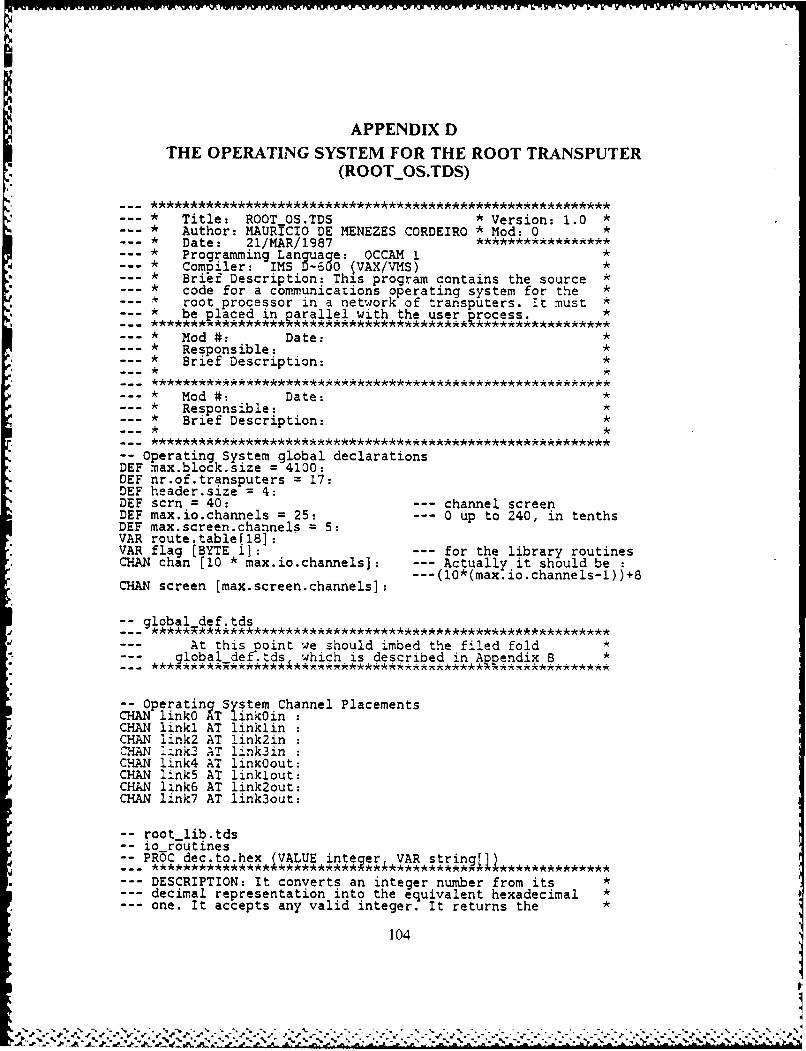
APPENDIX DTHE OPERATING SYSTEM FOR THE ROOT TRANSPUTER
(ROOT_0S.TDS)
* Title: ROOTOS.TDS *version: 1.0 ** Author: MAtIRICIO DE MENEZES CORDEIRO *Mod: 0** Date: 21/MAR/1987* Programming Language: OCCAM 1** Comoiler: IMS D-600 (VAX/VMS)*
* * Brii Description: This program contains the source* code for a communications operating system for the ** root processor in a network of transputers. It must ** be placed in*Rarallel with the user, roce ss.*
* Mod #: Date:** Responsible:*
* * Brief Description:*
* Mod #: Date:** Responsible:** Brief Description:*
-Operating System global declarationsDEF max.block.size = 4100:DEF nr of.transputers = 17:DEF header.siZe = 4:DEF scrn = 40: -- channel screenDEF max.io.channels = 25: -- 0 up to 240, in tenthsDEF max.screen.channels =5:VAR route.table[18]:VAR flag (BYTE 1]: -- for the library routinesCHAN chan [10 * max.io.channels]: --- Actually it should be:
CHAN screen [max.screen.channels]:10 ma ioc nel-)8
:-_global def.tds
-- At this aoint we should imbed the filed fold*-- global def tds which is described in Appendix B*
-- operatinkTSystem Channel PlacementsCHAN linkO Aiinkoin:CHAN linkl AT linklin:
*CHAN link2 AT link2in:ClIAN link3 AT linklin:CHAN ilnk4 AT linkO'out:CHAN link5 AT linklout:CHAN link6 AT link2out:CHAN link7 AT link3out:
-- root..lib.tdsl- o routinesPROC dec.to.hex IVALUE intener ,VRstring~j
*-- DESCRIPTION: It converts an integer number from its*decimal representation into the equivalent hexadecimal *one. It accepts any valid integer. It returns the*
104
f/%% d. *.- .. %.......
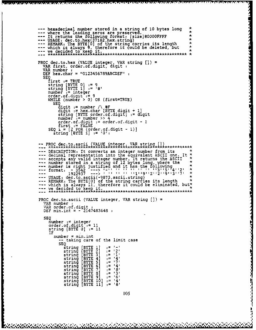
--- hexadecimal number stored in a string of 10 bytes long *where the leading zeros are preserved. *It returns the following format: [size]#0000FFFF *USAGE: dec.to.hex(37182,hex.string) *REMARK: The BYTE[0] of the string carries its length *which is always 9, therefore it could be deleted, but *we decided to keep it.
*i
PROC dec.to.hex (VALUE integer, VAR string []) =VAR first, order.of.digit, digitVAR number :DEF hex.char = "0123456789ABCDEF"SEirst := TRUE
string (BYTE 0] 9string [BYTE 1] : #1number := integerorder.of.digit := 9WHILE (number > 0) OR (first=TRUE)SEigit :number /\ #F
digit : hex.char [BYTE digit+ 11string [BYTE order.of.digit] : digitnumber := number >> 4order.of.diit : order.of.digit - 1first := FALSE
SEQ i = [2 FOR (order.of.digit - 1)]string [BYTE i] := '0':
-- PROC dec.to.ascii (VALUE integer. VAR string []
--- DESCRIPTION: It converts an integer number from its *decimal representation into the equivalent ASCII one. It *accepts any valid integer number. It returns the ASCII *number stored in a string of 12 bytes lon?, where the *number is right justified and it has-the ollowinq *format: - 3542 ---> 1-11 1 11 1 11 It 113115141121 *
1922937 ---> 1 1 11 1311191121121191131171 *USAGE: dec.to.ascii(-9873,ascii.string)REMARK: The BYTE[0] of the string carries its lenqthwhich is always 11, therefore it could be eliminated, but*we decided to keep it. *
PROC dec.to.ascii (VALUE integer, VAR string []) =VAR number :VAR order.of.digitDEF min.int = - 2147483648
SEQnumber := integer porder.of.digit : 11string [BYTE 0] 11IFnumber = min.int
-- taking care of the limit caseSEQ
string BYTE 2 : '2'string BYTE 3 : '1'
string BYTE 4 : '4'string BYTE 5 : 17tstring BYTE 6 := '4'string BYTE 7 '8'string BYTE 8' :131string BYTE 9 : '6'string BYTE 1'4'string BYTE 11] : '8'
105

TRUESEF
number = 0SEQ
string [BYTE 11 :=string [BYTE 11]:= '0'order.of .digit := 10
number < 0SEQnumber - - numberstring [BYTE 1] : -
TRUE --- number > 0string [BYTE 1] -=
-- building up the actual numberWHILE number > 0
SEQstring [BYTE order.of.digit] := (number \ 10) + '0'number := (number / 10)order.of.digit := order.of.digit - 1
SEQ i = [2 FOR (order.of.digit - 1)]string [BYTE i] := :
-PROC hex.to.dec (VALUE string , VAR integer OK
--- DESCRIPTION: It accepts a hexadecimal representation of *--- a number and converts it into an integer number. It *--- expects the byte[0] of the string to carry the size *
information of that "hex number". *USAGE: hex.to.dec ("#00003785",numbercvalid) *
hex.to.dec ("#1452",number,valid) *hex.to.dec ('#19574" ,number,valid)ascii.to.dec (hex.string,number valid) *
REMARK: Returns a boolean value FALSE in OK if the *--- strini is not in the correct format. *
-- ***** ** ***************************************************
PROC hex.to.dec (VALUE string [], VAR integer, OK) =SEQ
integer := 0IF
-- empty stringstring BYTE 01 = 0
OK := FALSE
-- hex numberstring [BYTE 0] <> 0IF-- starts with '#'string [BYTE 1] = 1#'VAR CountSEQ
OK := TRUECount := 2WHILE (Count <= string [BYTE 0]) AND OKVAR DigitSEQDEF hexChars = "0123456789ABCDEF"IF
IF Index = [1 FOR hexChars [BYTE 011hexChars BYTE Index] = string [BYTE Count]
Digit := Index - 1TRUEOK : FALSE
integer : (integer << 4) + DigitCount : Count + 1
106

-- otherwisestring [BYTE 1] <> 1#1OK := FALSE
SKIP :
-- PROC ascii.to.dec (VALUE string[I VAR inteier,,OK._***************** *********** * ****************
--- DESCRIPTION: It accepts an ascii decimal *representation of a number and converts it into an *integer number it expects the byte[O] of the string *to carry the size information of that "ascii number
--- USAGE: ascii.to.dec ("-3785",number,valid) *ascii.to.dec ("+1452",number,valid) *ascii.to.dec ("19574" ,number,valid) *
--- ascii.to.dec (string,number,valid) *--- REMARK: Returns a boolean value FALSE in OK if the--- string is not in the correct format.
PROC ascii.to.dec (VALUE string [3, VAR integer, OK) =SEQ
integer := 0IF-- empty stringstring LBYTEO0 = 0OK := FALSE
-- numberstring [BYTE 0] <> 0VAR SignVAR StartVAR LengthSEQ
OK : TRUEIF
-- negativestring [BYTE 1] =
Eign := - I
Start : 2Length := string [BYTE 0- 1
-- positivestring [BYTE 1] <>
SEQSign : 1Start : 1Length : string [BYTE 0]
-- convert to integerSEQ Index = (Start FOR Length]VAR DigitSEQDigit := string [BYTE Index]IF
('0' <= Oigit) AND (Digit <= 9')integer := (integer 10) x (Digit - '0')
TRUEOK := FALSE
integer := integer * Sign
SKIP :
-PROC write.strinq (VALUE strin[)
--- DESCRIPTION: Writes a given string to the screen, in a *byte by byte fashion. It requires that the string which *
107
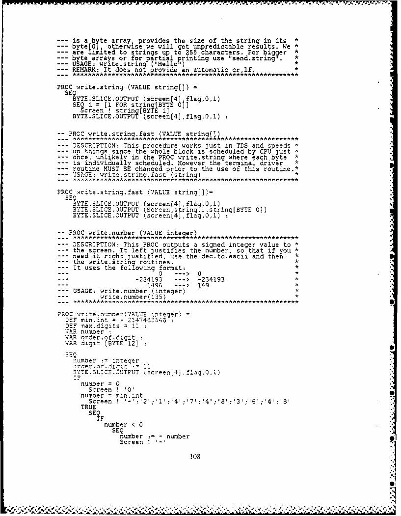
--- is a byte array, provides the size of the string in its *byte[0]4 otherwise we will get unpredictable results. We *are limlted to strings up to 255 characters. For bigger *byte arrays or for partial printing use "send.string *USAGE: write.string ("Hello') *REMARK: It does not rovide an automatic cr if. *
PROC write.strinq (VALUE string(]) =SEQBYTE.SLICE.OUTPUT (screen[4J flag,0,1)SE? i = [I FOR string[BYTE 0]
Screen ! string[BYTE i]BYTE.SLICE.OUTPUT (screen[4],flag,0,1)
-- PROC write.string.fast (VALUE string[])
--- DESCRIPTION: This procedure works just in TDS and speeds *--- up things since the whole block is scheduled by CPU just *
ohce, unlikely in the PROC write.string where each byte *is individually scheduled. However the terminal driver *routine MUST BE changed prior to the use of this routine.*--USAGE: wrie ;st ringfast (string) .*.
PROC rite-string.fast (VALUE string[], =
SEQBYTE.SLICE.OUTPUT (screen(4],flag,0,1)BYTE.SLICE.DUTPUT (Screen stringl,string[BYTE 0])BYTE.SLICE.0UTPUT (screen[4],flag,0,1)
-PROC write.number (VALUE itgr
--- DESCRIPTION: This PROC outputs a signed integer value to *--- the screen. It left justifies the number, so that if you *
need it right justified, use the dec.to.ascii and then *--- the write.string routines. *
It uses the following format: *0 --- >0 *
--- 234193 ---> -234193 *--- 1496 ---> 149 *--- USAGE: write.number (integer) *--- write.numberI135 ) *
?ROC -4rit..number('7ALUE integer)DEF min .nt = - --47483H48DEF- max.digits = 1VAR number :VAR order.of.digitVAR digit [BYTE 12] :SEQ
number := integer -.)rder.of. iiz := ii I-3YTE.SLICE.UTPUT ,screen(4j,flag,0,1)
number = 0Screen ! '0'
number = min.intScreen .' '- ;'2';' ';1'4';1'7';'4'; 8 ;131; ;14
TRUESE
number < 0SEQ
number : - numberScreen !
108
.~~~ .. .. .- s.. .
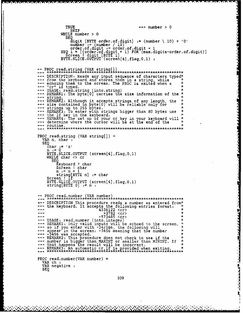
TRUE --- number > 0SKIP
WHILE number > 0SEgigit [BYTE order.of.digit] := (number \ 10) + '0'
number := (number / 10)order.of.digit := order.of.digit - 1
SEQ i = [(order.of.diqit + 1) FOR (max.digits-order.of.digit)]Screen ! digit [BYTE i]
BYTE.SLICE.OUTPUT (screen(4],flag,0,1)
-PROC read.strinq (VAR string)
DESCRIPTION: Reads any input sequence of characters typed*from the keyboard and stores them in a string, whileechoing them to the screen. The PROC is exited when a *"cr" is typed. *USAGE: read.string Kinto.string) *REMARK1: The byte[0] carries the size information of the *string. *REMARk2: Although it accepts strings of any length, the *
--- size contained in byte[0] will be reliable only for *strings up to 255 bytes. *
--- REMARK3: To enter with strings bigger than 80 bytes use *--- the lf key in the keyboard. *
REMARK4: The set up of your cr key in your keyboard will *determine where the cursor will be at the end of the *routine. *
PROC read.string (VAR string(]) =VAR n, charSEQ
char := 1z'n := 0BYTE.SLICE.OUTPUT (screen[4],flag,0,1)WHILE char <> cr
SELeyboard ? char
Screen ! charn := n + 1string[BYTE n] := char
Screen ! lfBYTE.SLICE.OUTPUT (screen[4],flag,0,1)string[BYTE 0] := n :
-PROC read.number (VAR number)
DESCRIPTION This procedure reads a number as entered from*the keyboard. It accepts the following entries format: *
--- 4536122 <cr> *--- +3782 <cr> *
--- 573485 <cr> *--- USAGE: read.number (into.integer)
REMARK1: Only valid inputs will be echoed to the screen, *so if you enter with -34r5&6, the following will *appear in the screen: -3456 meaning that t e number *-3456 was accepted. *REMARK2: This procedure does not check to see if the *number is bigger than MAXINT or smaller than MININT. If *that happens the result will be incorrect. *REMARK3: An automatic cr lf is provided when exiting. *
***vde w********** *****
PROC read.number(VAR number) =VAR ch :VAR negativeSEQ
109
IP * . - .... .. '.. *\ .. ,
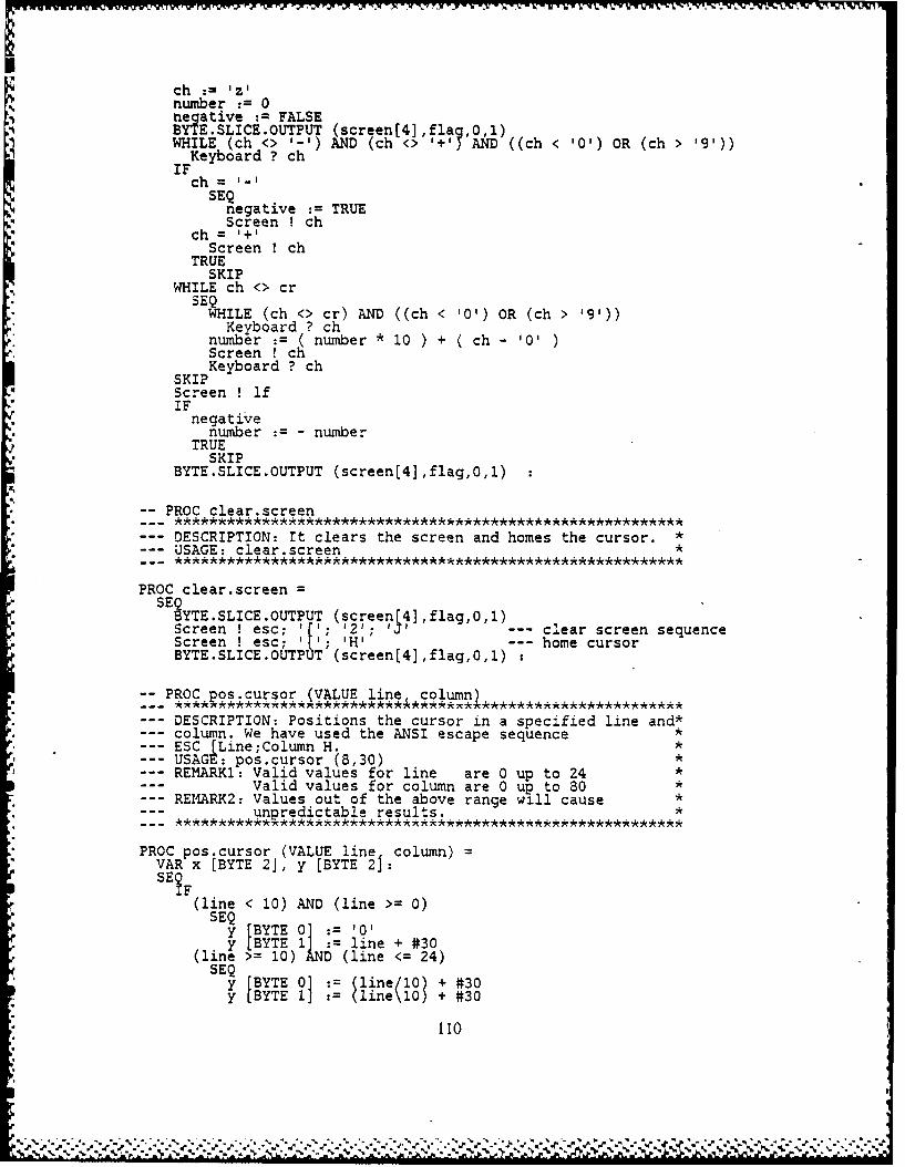
ch : znega tive :=FALSEBYTE.SLICE OUTPUT (screen(4],fla?,0,1)
WHILE(ch > -- ') AND (ch <> '+' AND ((ch < '0') OR (ch > 19'))
ScKeboreen chch= _
Screen 1c
TRUESKIP
WHILE ch <> cr
WHLILE (ch <> cr) AND ((ch < '0') OR (ch ' 9'))Keyboard ? ch
number :=( number*l10 ) + ( ch - '0')Screen !ch
SKI Kybord? chScreen !IifIF
negative* number :=-number
TRUE* SKIP
BYTE.SLICE.OUTPUT (screen(4] ,flag,O,1)
-PROC clear.screen
--DESCRIPTION: It clears the screen and homes the cursor.*--USAGE: clear.screen
PROC clear.screenSE 3YTE .SLICE .OUTPUT (screen -- cear cree seqenc
Screen ! esc T creen(4,clarfcreeseqencScreen ! esc; -[' 'H' - home cursorBYTE.SLICE.OUTPUT (screen[4],flag,O,1)
~PROC os cursor (VALUE line column)
--DESCRIPTION: Positions the cursor in a specified line and*column. We have used the ANSI escape sequence*
--ESC (Line;Column H.*--USAGE: pos.cursor (8,30)*REMARKi: Valid values for line are 0 up to 24*
Valid values for column are 0 up to 80*--REI4ARK2: Values out of the above range will cause*
unpredictable results.*
PROC pos.cursor (VALUE line column)VAR x [BYTE 2], y (BYTE 21:SE ?
(line < 10) AND (line >= 0)SEQy [BYTE 0]: 0'*y[BYTE 1] line + #30
(ine >= 10) AD (line <= 24)SEQY [BYTE 0] : (line/10 + #30yLBYTE 11 (line\10) + #30
110
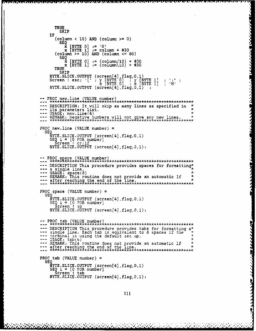
TRUESKIP
(column < 10) AND (column >= 0)SEQ
x EBYTE 1]A column + #30(column >= 10) AND (column <= 80)SEQx [BYTE 0] 1 column/10) + #30
TREx IBYTE 1j :(column\10) + #30
SKIPBYTE.SLICE OUTPUT (screen(4] ,flag,0,1)Screen ! esc; I[' ; y IBYTE 01 ; y BYTE 1] ;' ;
x [BYTE 0] X [BYTE V ; 'H'BYTE.SLICE.OUTPUT (screen[4J, slag,O 0,1)
-PROC new.line (VALUE number
DESCRIPTION: It will skip as many lines as specified in*--its parameters list.*--USAGE: new.line(4)*
--- REAK-eatv ubr will not gi.ve any new lines.
PROC new.line (VALUE number)SEQ
BYTE.SLICE.OUTPUT (screen[4] ,flag,O,l)SEQ i =[0 FOR number]
Screen ! cr;lfBYTE.SLICE.OUTPUT (screen(j4],flag,0,1)*
~PROC sp ace (VALUE number
--DESCRIPTION This procedure provides spaces for formatting*a single line.*
--USAGE: space(8)*--REMARK: This routine does not provide an automatic lf *--after reaching the end of the line.*
PROC space (VALUE number)SEQ
BYTE.SLICE.OUTPUT (screenfj41,flag,O,1)SEQ i = [0 FOR number]
Screen ! soBYTE.SLICE.OUTPUT (screen[4],flag,O.1):
~PROC tab (VALUE numb--)
--DESCRIPTION This procedure provides tabs for formatting a*sigeline. Each tab ieqvaent to 8 spaces if the
--: errninal is using the default set up.USAGE: tabj6)*REMARK: This routine does not orovide an automatic If *after reachinjthe end of the line.*
PROC tab (VALUE number)SE 3YTE.SLICE.OUTPUT (screen[4],flag,O,1)
SE~ci = (0 FOR number]Sreen I tab
BYTE.SLICE.OUTPUT (screen[4],flag,O,1):
r. q1N,
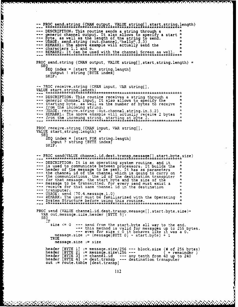
aVWj-V -W-W1% Wa~ - .
::PROC send.string (CHAN output VALUE strin ~ sri.legh
DESCRIPTION: This routine sends a string through a *generic channel output. It also allows to specify a start *byte, as well as the length of the string to send. *
- USAGE: send.string (out.channel,"hello",3,3) *--- REMARKi: The above example will actually send the *
characters 1,1 and o. *REMARK2: It can be used with the channel Screen as well. *
PROC send.string (CHAN output, VALUE string[],start,string.length) =SE EQ index = [start FOR string.length]
output ! string [BYTE index]SKIP:
-- ?ROC receive.string (CHAN input, VAR string(],VALUE start string.length)
--- DESCRIPTION: This routine receives a string through a *generic channel input. It also allows to specify the *starting byte, as well as the number of bytes to receive *from the incoming string. *
--- USAGE: receive.strina "out.channelstring.in,3,2) *--- REMARK1: The above example will actually receive 2 bytes *
from the incominj string, starting at byte 2. *
PROC receive.string (CHAN input, VAR string[],VALUE start,string.length) =
SErEQ index = [start FOR string .length]input ? string (BYTE index?*
SKIP:
-- PROC send(VALUE channel.id, dest.transp message[],,start.bytesize)-*** *********** ****** 7w***r ,r 4 ****
--- DESCRIPTION: It is an operating system routine, and it *is used to communicate between processors. It builds the *header of the message to be sent. It has as parameters *the channel id of the channel which is going to carry on *the communications, the id of the destination transputer *for that message, the start byte and the size of the *message to be transmitted. For every send must exist a *receive for that same :hannel id in the destination
--- transputer. *--- USAGE: send (70,4,message,1, I
REMARK: The user must be familiarized with the Operating *Sstem Structure before using this routine.
PROC send (VALUE channel.id,dest.transp,message[],start.byte,size)=VAR out,message.size,header [BYTE 5]:SEO-F
size <= 0 --- send from the start.bvte all way to the end.this method is valid tor messages u to 255 bytes.even for size < 0 it behaves like it was a 0.
message.size : (message[BYTE 0) - start.byte) + 1TRUE
message.size : size
header BYTE I : message.size/256 --- block.size (# of 256 bytes)header BYTE 2 message.size\256 --- ( + remainderheader [BYTE 3 channel.id --- any tenth from 40 up to 240
header I BYTE 4 J dest.transp --- destination transputerout : route .table [dest.transp]
112

BYTE.SLICE.OUTPUT (chan[channel.id + out] ,header,3,1) --- ready flagIFout = 4
SE YTE.SLICE.OUTPUT link4,headerj,header.size)
BYTE.SLICE.OUTPUT link4,message,start.byte,message.size)out = 5SEO
SYTE.SLICE.OUTPUT (link5,header,l,header.size)BYTE.SLICE.OUTPUT linkS,message,start.byte,message.size)
out = 6SE YTE.SLICE.OUTPUT (link6,header,l,header.size)BYTE.SLICE.OUTPUT link6,message,start.byte,message.size)
out = 7SEQ
BYTE.SLICE.OUTPUT (link7,header,l,header.size)BYTE.SLICE.OUTPUT (link7 message,start.bytemessage.size)
BYTE.SLICE.OUTPUT (chan[channel.id + out],header,3,l): --- done flag
-- PROC receive (VALUE channel.id VAR messaqei], messale lenth[])--- DESCRIPTION: It is an operating system routine, and it *
is used to communicate oetween processors. it receives *--- the incoming message, and provides as an output parameter *
the size of the message just received. The parameter *--- channel id must have an exact match with the send *
operation which originated that message. *USAGE: receive (70,message.in,size)*
--- REMARK1: The user must be familiarized with the Operating *Sstem Structure before using this routine.RKMARK2: Notice that the message.lenqth output parameter, *must be a unity array of integers, while the message *itself must be declared as an array of bytes. ********************************* *************
PROC receive (VALUE channel.id,VAR message[],message.length[])=SE oD.SLICE.INPUT (chanrchannel.id ,message.length,On1BYTE.SLICE.INPUT (chan[channel.idl ,message,l,messag. ength[O]):
-- utilities-- PROC tick.to.time (VALUE start sto boardMe)
--- DESCRIPTION: It expects the board type which can be : *board.type = 0 ---- > OPS (VAX VMS) *board.type = 1 ---- > B001 (T414:12.5 MHz) *board.type = 2 ---- > B002 *board.type = 31 ---- > B003 (T414:15 MHz - high pri) *board.type = 32 ---- > B003 T414:1 5MHz - low pri) *board.type = 4 ---- > B004 *
and 2 signed integers representing some tick values *obtained by an assignment of the type TIME ? time.var *It then outputs the corrected elapsed time in hours, min,*sec and msec, already taking into account the fact that *the timer wraps around when it reaches MAXINT or MININT. *USAGE: tickk.to.time (timel,time2,31) *REMARK: Althou h it takes care of the wrapping, it won't *keep track of £he number of times you have completed one *full cycle of the timer. In order to solve this problem *you should record roughly the start time. For example, in*the VAX/VMS, the full cycle of the timer is 7.2 min, so *if you get the elapsed time of 5 min 7 sec 320 msec and *you have got a rough total time of 12 minutes, then the *real total time is 12 min 19 sec 320 msec. *.__ **********************************************************
113
rS

PROC tick.to.time (VALUE start, stop, board.type) =-- constant definitionsDEF vax.sec =10000000 : --- hundreds of nsec/secondDEF vax.mili = 10000 : hundreds of nsec/milisecondDEF bOO1.sec = 625000 : # of 1.6 usec/secondDEF b001.mili = 625 : # of 1.6 usec/milisecondDEF b003h.sec = 1000000 : # of usec/secondDEF b003h.mili = 1000 : # of usec/milisecondDEF b0031.sec = 15625 : # of 64 usec/secondDEF b0031.mili = 16 : # of 64 usec/milisecond
DEF max.number.of.ticks = 2147483648 --- maximum integer (2**31)VAR elapsed.tick :VAR factorl, factor2VAR msec, tot.sec, sec, min, hr
SEF
board.type 0 --- VAX VMSSEactorl vax.sec
factor2 vax.mili
board.type = 1 --- B001SE actorl bOO1.sec
factor2 bOO1.mili
board.type 2 --- B002SKIP --- not implemented
board.type = 31 --- B003 in high prioritySE actorl := b003h.sec
factor2 b003h.mili
board.type = 32 --- B003 in low prioritySE actorl := b0031.sec
factor2 bG031.mili
board.type = 4 --- B004SKIP --- not implemented
elapsed.tick stop - startIF
elapsed.tick < 0elapsed tick := elapsed.tick + max.number.of.ticksTRUESKIP
tot.sec elapsed.tick/factorlhr tot.sec/3600min (tot.sec\3600)/60sec tot sec\ 6msec (elapsed .tick\factorl)/factor2
-- output time to screenwrite.number (hr)write.string ("hr ")write.number (min)write.string (" mn ")write.number(sec)write.string (" sec ")write.number(msec)write.string (" msec")
PROC dump (VALUE beqin.address count)
114
lef4
_ . , *.', .V- .V.< , , -, , . . - - . - . - * ... , .. -. .-.. ,' j -, ;.. . . - . .-: . , .. . ...-... , .. ..

--DESCRIPTION: This procedure dumps the memory starting at*--the given "begin.address". The value for the*
"begin.address" can be either in hex or decimal.*--The count value determines how many words in memory will*be retrieved.*
--USAGE: a) dump (#80003540,100)*b dm 1024 4%
REMARKi: When specifying the count value remember that--- he etrev~lis oneby words, not bytes!!!
-REMARK2: If count is no~ a multiple of 4 it will use the*closest upper multiple.*
-REMARK3: Negatives or zero values for count although *acce~ ted ,will iv ou no outout.*
PROC dump (VALUE begin.address, count)=VAR word.read:VAR hex.value 19], hex.addrI9]:VAR address, align, times:
SEQtimes := 0new.line(i)address : egin.address--. a.ligning a given addressalign := address\4IF
alicgn <> 0address := address - align
TRUESKIP
WHILE times <= countSEQwrite.string "address "dec.to.hex (adress,hex.addr)write.string (hex.addr?write.str n " -> 'SE i( OR 4]
SETW0RD (word.read,address)dec.to.hex (word.read,hex.value)write.string hex.value)space (2)t~mes := times +- 1
address := address + 16new. line 1I)
SKIP:
~PROC transfer.rate (VALUE start stop board.t,4Re nr of bytes,VAR rate)
--DESCRIPTION: it is basically the same routine as*--tick.to.time, with the only diz .erence :hat izreturns a--rate value in Kbits/sec instead of a time value.--USAGE: transfer.rate (timel time2,31,4096,rate)*REMARK: If further information is needed, please refer to*routine tick.to.time*
PROC transfer.rate (VALUE start,stop,board.type,nr.of.bytes,VAR rate)=-constant definitions
DEF vax.sec =10000000 : -- hundreds of nsec/secondDEF b0O1.sec = 625000 : # of 1.6 usec/secondDEE bOO3h.sec = 1000000 : # of usec/secondDEF b0031.sec = 15625 : # of 64 usec/secondDEF max.number.of.ticks =21471483648 -- maximum integer (2**31)
115
%I
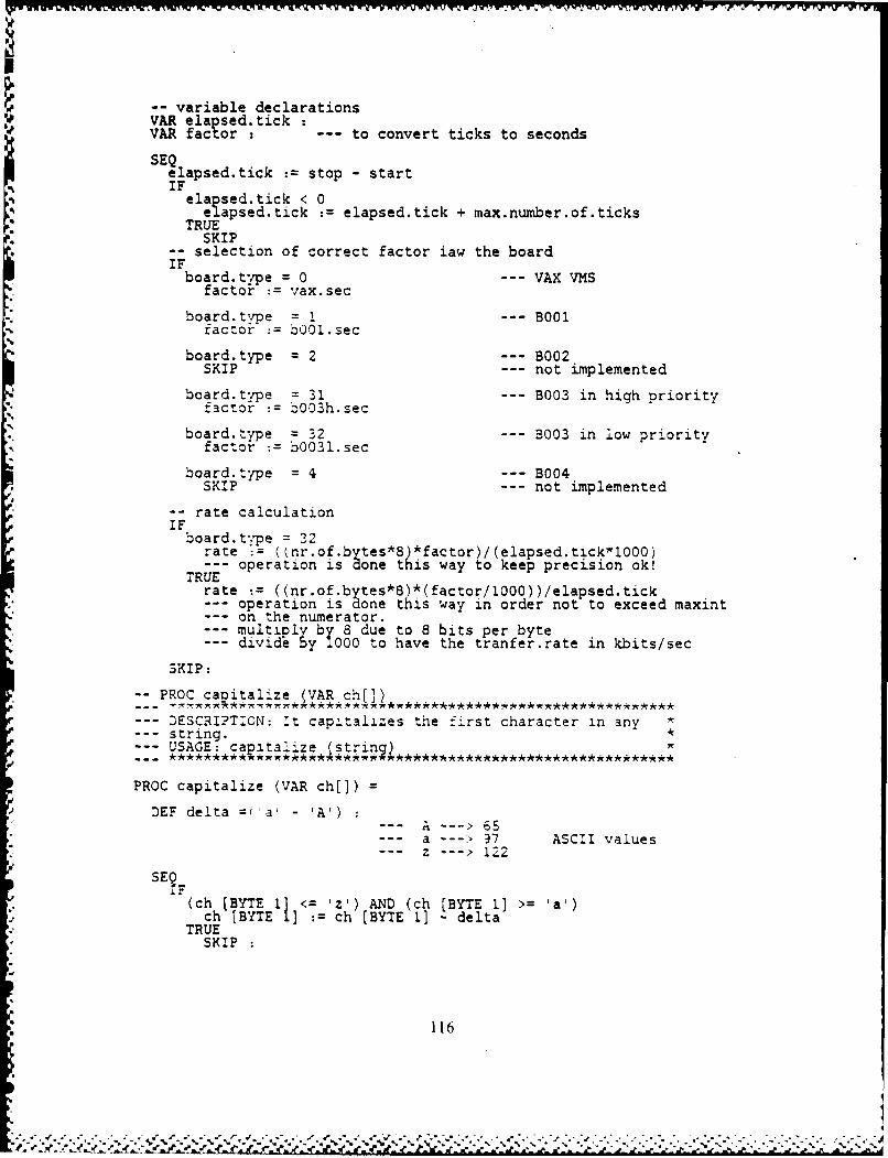
-- variable declarationsVAR ela psed.tick 0VAR facor --- to convert ticks to seconds
sEQelapsedtick := stop - startIFelased.tick < 0
flapsed.tick := elapsed.tick + max.number.of.ticksTRUESKIP
-selection of correct factor law the boardIFboard.t-yoe =0 --- VAX VMS
factor : vax.sec
board typ = 1 --- B001factor :=b001.sec
board.type = 2 --- B002
SKIP --- not implemented
board.type = 31 --- B003 in high priorityfactor := b003h.sec
board.type = 32 --- 3003 in low priorityfactor := b0031.sec
board type = 4 --- B004SKIP --- not implemented
-- rate calculationIFboard.t'pe = 22
rate := ( nr.of.bytes*S)*factor)/(elapsed.tickwlO00)--- operation is done this way to keep precision ok!TRUErate := ((nr.of.bytes*8)*(factor/1000))/elapsed.tick
operation is none this way in order not to exceed maxint--- on the numerator.--- multiply by 8 due to 8 bits per byte--- divide by 1000 to have the tranfer.rate in kbits/sec
SKIP:
- PROC caoitalize (VAR chj])
--- DESCRIPT:ON: :t capitalizes the first character in anystring. *USAGE: caDitalize strin)
PROC capitalize (VAR ch[]) =
DEF delta ='a - 'A') :
a ---: 97 ASCII values
--- z ---> 1Z25E9FIF (ch [BYTE 1] <= 'z') AND (ch [BYTE 1] >= 'a')
ch [BYTE 1] :ch [BYTE 1] - deltaTRUE
SKIP
116
40 %. r- W
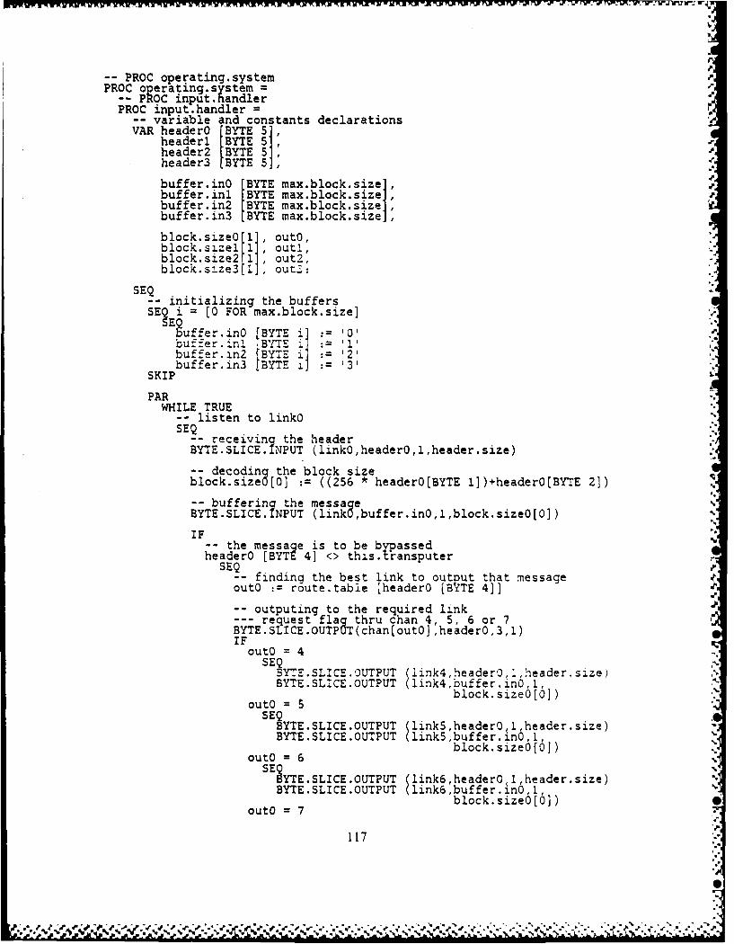
PROC operating.systemPROC o erating.system=
-- PROC input, handlerPROC input.handler =
-vari.able and constants declarationsVAR headerO BYT 5headeri BYTE 511
header2 BYTE 5]header3 LBYTE 5],
buffer.inQ BYT max.block.size1,buffer.inl BYTE max.block.sizeJbuffer.in2 LBYTE max.block.size]buffer.in3 BYTE max.block.size]
block.sizeO [11, outo,block.s2.zel [1] outi,block.size2 1ll out2,block.size3 [I, out-:
- -_ initializing the buffersSE? i = [0 FOR max.block.size]
Eguffer.in0 BYTE 50bu"fier.in. BYT '1buffe-r.in2 BYTE i]: 2'buffer.in3 BYTE- 111 1 3'
SKIP
PARWHILE TRUE
-listen to linkoSEQ
-- receiving the headerBYTE.SLICE. INPUT (linkO,headerO,l,header.size)
-- decoding the block sizeblock.sizeO (0] := ((256 * headerO[BYTE l])+headerO[BYTE 2])
-buffering the messageBYTE.SLICE. IIPUT (linkO,buffer.inO,l,block.sizeO[0])
IF-- the message is to be bypassedheaderO [BYTE 4] <> thi.s. transputer
SEQ P
-finding the best link to output that messageoutO :=route.table [headerO [BY~TE 4]
-outputing to the required linkrequest flag thru chan 4, 5, 6 or 7
BYTE.SLICE.OUTPtJT(chan~out0] ,headerO,3,I)IF
autO = 4SEQ
BYTE.SLICE.0UTPUT (1ink4,header04Iheader.sl.ze)BYTE.SLICE.OUTPUT (link4,buffer.in0,1,autO =block.sizeO[O])
SEQBYTE.SLICE.OUTPUT link5,header0 1 ,header.size)BYTE.SLICE.OUTPUT (link5,buffer. n0,1,
b lock.sizeo (0])auto = 6
SEOSYTE.SLICE.OUTPUT (link6,headero,1,header.size)BYTE.SLICE.OUTPUT (link6 buffer.ina, 1,
'block.sizeIIO])outO =7
117
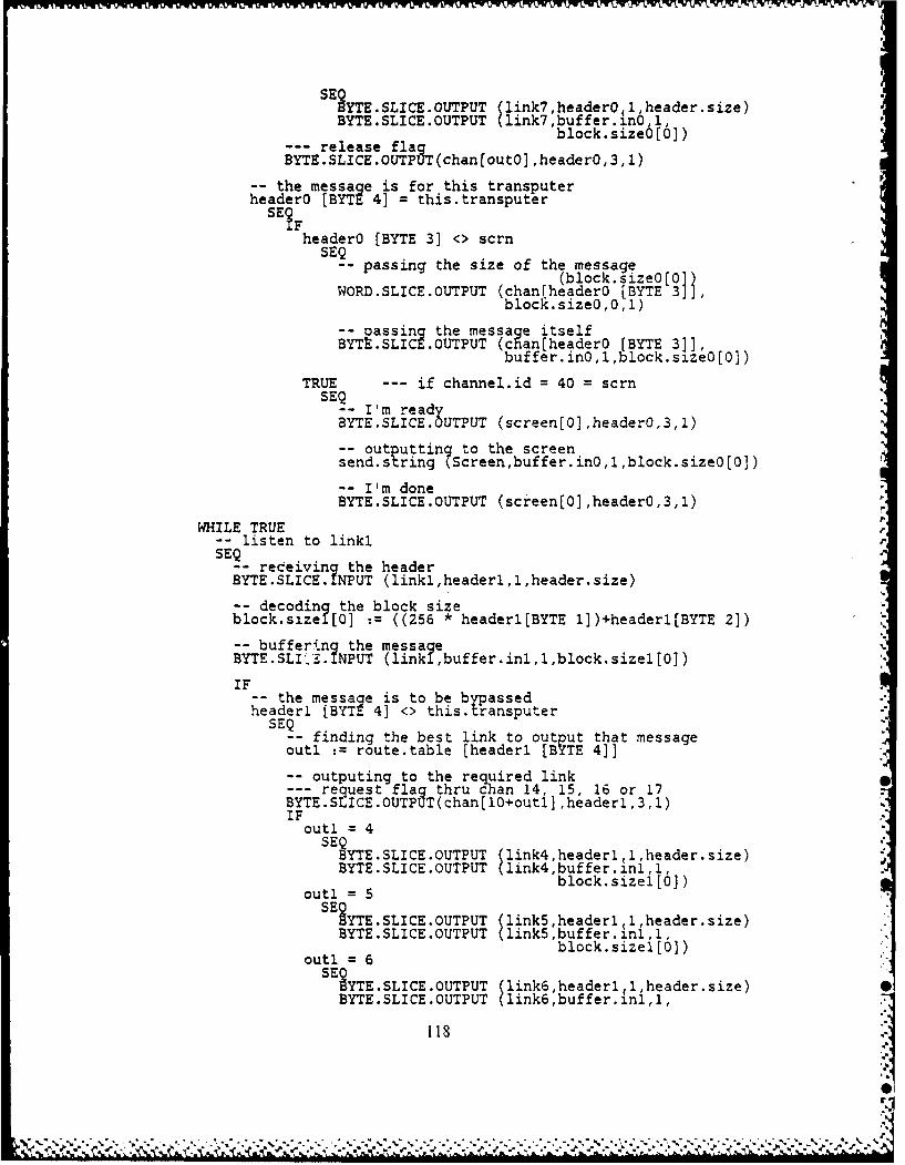
SE YTE.SLICE.OUTPUT (link7,headerOl1 header size)BYTE.SLICE.OUTPUT (link7,buffer.in6,1,
--release flag block.size6[6])BYTE.SLICE.OUTPUT(chan~out0],header0,3,1)
-the message is for this transputerheaderO [BYTE 4] = this.transputer
SE ?F
headerO [BYTE 3] <> scrnSE- passing the size of the message
(block. size0 [0]WORD.SLICE.0UTPUT (chanrheader0 [BYTE 3]],
block. size0 ,0 ,1)
-- passing the message itselfBYTt.SLICE.OUTPUT (chan[header0 [BYTE 31],
buffer.in0, , block.sizeO[0])
TRUE -- if channel.id = 40 = scrnSEQ- I'm ready
BYTE.SLICE .OUTPUT (screenjjO],header0,3,1)
-oututting to the screensend.string Screen,buffer.inO,l,block.sizeO[0])
-- I'm doneBYTE.SLICE.OUTPUT (screen[0] ,header0,3,1)
WHILE TRUE-- listen to linkiSEQ- rec eiving the headerBYTE.SLICE. IPUT (linkl,headerl,1,header.size)
-- decoding the block sizeblock.size ( 0] :=((256 * headerl[BYTE 1] )+headerl[BYTE 2])
-- buffering h esgBYTE.SLI',~. I PUT (linkl buffer.inl,l,block.sizel[0])
IF__ the message is to be bypassedheaderi [BYTE 4] <> this.transputer
SEQ-- finding the best link to outp ut that messageoutl : route.table [headeri [BYTE 4]]
-outputing to the required linkrequest flag thru clan 14, 15, 16 or 17
BYTE.SLICE.OUTPUT(chan[10+outl] ,headerl,3,1)IF
outl 4SEQ
BYTE.SLICE.OUTPUT (link4,headerl 1,header.size)BYTESLIE.0TPUT (link4,buffer.inl,1
outl= 5block. size [0))
SEYTE.SLICE.OUTPUT (link5,headerl (1,header.size)BYTE.SLICE.OUTPUT (linkS buffer.inl.1
block.sizel [0)outl = 6
SE SYTESLICEOUTPUT (link6 ,headerl ( 1,header.size)
BYTE.SLICE.OUTPUT (link6,buffer.inl,l,
1181

outi = 7block.sizel[0j)S YESLICE.OUTPUT (link7,headerl 1,header.size)
BYTE.SLICE.OUTPUT (link7,buffer.inl,1,
--release flag block. sizel.[01)BYTE.SLICE.OUTPU( chan [ 0+outl] ,headerl,3,1)
-the message is for this transputerheader. [BYTE 4] = this.transputer
SE Theader. [BYTE 3] <> scrn
--Qpassing the size of the message(block, size.[0]
WORD.SLICE.OUTPUT (chanfheader. [BYTE 3]],bloc'. size.,J,1.)
-p assing the message itselfBYT SLICE.OUTPUT (c an[headerl [BYTE 31],
buffer.inl,l ,block.sizel[0])
TRUE --- if channel.id = 40 = scrn
I' m readyBYTE.SLICE.OUTPUT (screen[Ij,headerl,31,l)
-; outputting to the screensend.string(Screen,buffer.inl,l,block.sizel[Q])
-- I'm doneBYTE;SLICE.OUTPUT (screen[lj,headerl,3,1)
WHILE TRUE-listen to link2-EQ- receiving the headerBYTE.SLICE. I PUT (link2,header2,1,header.size)
-decoding the block sizeblock.size2[ 0] :=((256 * header2[BYTE 1] )+header2[BYTE 2])
-- buffering the mess ageBYTE.SLICE. I PUT (link2 buffer.in2,1,block.size2[0])
__ the messagqe is to be bypassedheader2 [BYTE 4] <> this. transputer
--Q finding the 'zest'link to output that messageout2 := route.table [header2 [B YTE 4]]
-outputing to the required linkrequest flac thru chan 24, Z5, 26 or 27
3YTE.3LiLCE.OUTPtOT(chan[20+out2] ,header2,3,I)IF
out2 = 4SE 3YTE.SLICE.OUTPUT (link4 ,header2,l,header.size)
BYTE.SLICE.OUTPUT (link4,buffer.in2,1,
out2 block.size2[0])
SE YTE.SLICE.OUTPUT link5 header2 12,header.size)BYTE.SLICE.OUTPUT link5,buffer.in2,1,
out2 = 6 block.size2[O])SEQ
119
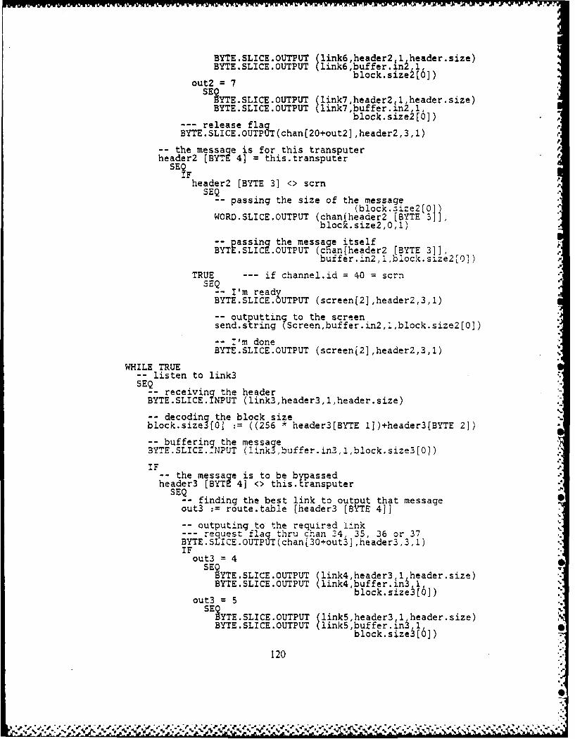
BYTE.SLICE.OUTPUT (link6,header2,l,header.size)BYTE.SLICE.OUTPUT (link6 buffer. in2, 1,
out2 ='7block.size![0])SE ?YTE.SLICE.OUTPUT (link7 ,header2 I1,header.size)
BYTE.SLICE.OUTPUT (link7,buffer.in2,l,
--release flag block.size2[01)BYTE.SLICE.OUTPUT(chan[20+out2] ,header2,3,l)
-the message is for this transputerheader2 [BYTE 4] = this.transputer
SE ?
header2 [BYTE 3] <> scmnSE- passing the size of the message
(block. 3ize2 [0]WORD.SLICE.OUTPUT (chantheader2 [BYTE 31],
block .size2,0,l)
p-assing thepmessag itselfBYTE.SLICE OUT UT (c an[header2 [BYTE 3]].
buffer.in2,1,block .size2[03)
TRUE -- if channel.id = 40 = scrnSE- I'm readyBYTE.SLICE .OUTPUT (screen(2],header2,3,I)
-- otputtin to the screensend.s ring(Screen,buffer.in2,1,block.size2Io])
-- I'm doneBYTE.SLICE.OUTPUT (screen[2],header2,3,l)
WHILE TRUE-- listen to link3SEQ
-- receiving the headerBYTE.SLICE. INPUT (link3,header3,l,header.size)
-- decoding the block sizeblock.size30 [0 = ((256 * header3[BYTE 1])+header3[BYTE 21)
-- buffering the messageBYTE.SLIC...NPUT (link3,buffer.in31,1,bl~ock.size3[0])
IF-- the messag~e is to be bypassedheader3 [BYTE 4] <> this. transputer
SEQ_-finding the best link to output that message
out3 :=route.table [header3 [BYTE 4]]
-outputing to the required !linkrequest flag thru chan 314, 35, 36 or 37
BYTE.SIICE.OUTPUT(chan30-out3] ,header3,3,1)IFout3 = 4
SEQBYTE.SLICE.OUTPUT (link4,header3,1,header size)BYTE.SLICE.OUTPUT (link4,buffer.in~ 1
out3 = lock.size~iI 6])SEO
?YTE.SLICE.OUTPUT (link5,header3 1(1 header.size)BYTE.SLICE.OUTPUT (link5,buffer. n 1
block.size~iI6])
120
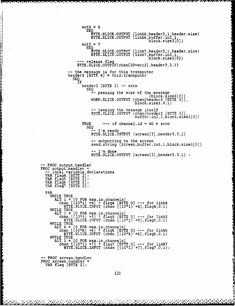
out3 =6SEYTE.SLICE.OUTPUT (link6, header3(l,header.size)BYTE.SLICE.OUTPUT (link6,buffer ;n3i,1,block. size3 0
out3 =7SEYTE.SLICE.OUTPUT (link7,header3,l,header.size)
BYTE.SLICE.OUTPUT (link7,buffer. n3,1,
--- release flaa block.size3[0])BYTE.SLICE.OUTPUT(chani30+out31 ,header3,3,l)
-the message is for this transputerheader3 (BYTE 4] = this.transputer
SE Theader3 [BYTE 3] <> scmn
SEQ-passing the size of the message
(block. size3 [01WORD.SLICE.OUTPUT (chanllheader3 [BYTE 3]],
block. size3, 0.1)
p- assing the message itselfBYTt.SLICE .OUTPUT (chan[header3 [BYTE 31],
buffer. in3, , block.size3 [0])
TRUE -- if channel.id = 40 = scrnSEQ
-- I'm readyBYTE.SLICE .OTPUT (screen[3],header3,3,1)
-- outputting to the screensend.string(Screen,buffer.in3,1,block.size3(0])
-- I'm doneBYTE.SLICE.OUTPUT (screen[3],header3,3,1)
-PROC output.handlerPROC output.handler =
-local variable declarationsVAR flag4 BYTE 21VAR flagS rBYTE2VAR flag6 [BYTE 2]VAR flag7 [BYTE 21:
PARWHILE TRUE
ALT i = [0 FOR max.io.channels]chan [(10*i) +4] ? flag4 [BYTE 0] -- for link4
BYTE .SLICE.INPUT (chan 1(10*i) +4],flag4,0,1)WHILE TRUE
ALT j = 0 FOR max.io.channels]chan [(10*j) +5] ? flagS [BYTE 0] -- for linkS
BYTE.SLICE.INPUT (chan 1(10*j) +5],flag5,0,1)WHILE TRUE
ALT k = [0 FOR max.io.channels]chan [(0*k) +6] ? flag6 [BYTE 0] -- for link6
BYTE SLICE.INPUT (chan [(10*k) +6],flag6,0,1)WHILE TRUE
ALT 1 0 C FOR max.io.channels]chan [(10*1) +7] ? flag7 [BYTE 0] -- for link7
BYTE .SLICE. INPUT (chan 1(10*1) +73,flag7,0,l):
-PROC screen.handlerPROC screen.hand.erVAR flag (BYTE 2]:
121
~ **~*** .*..p..'. *.-*~.*........
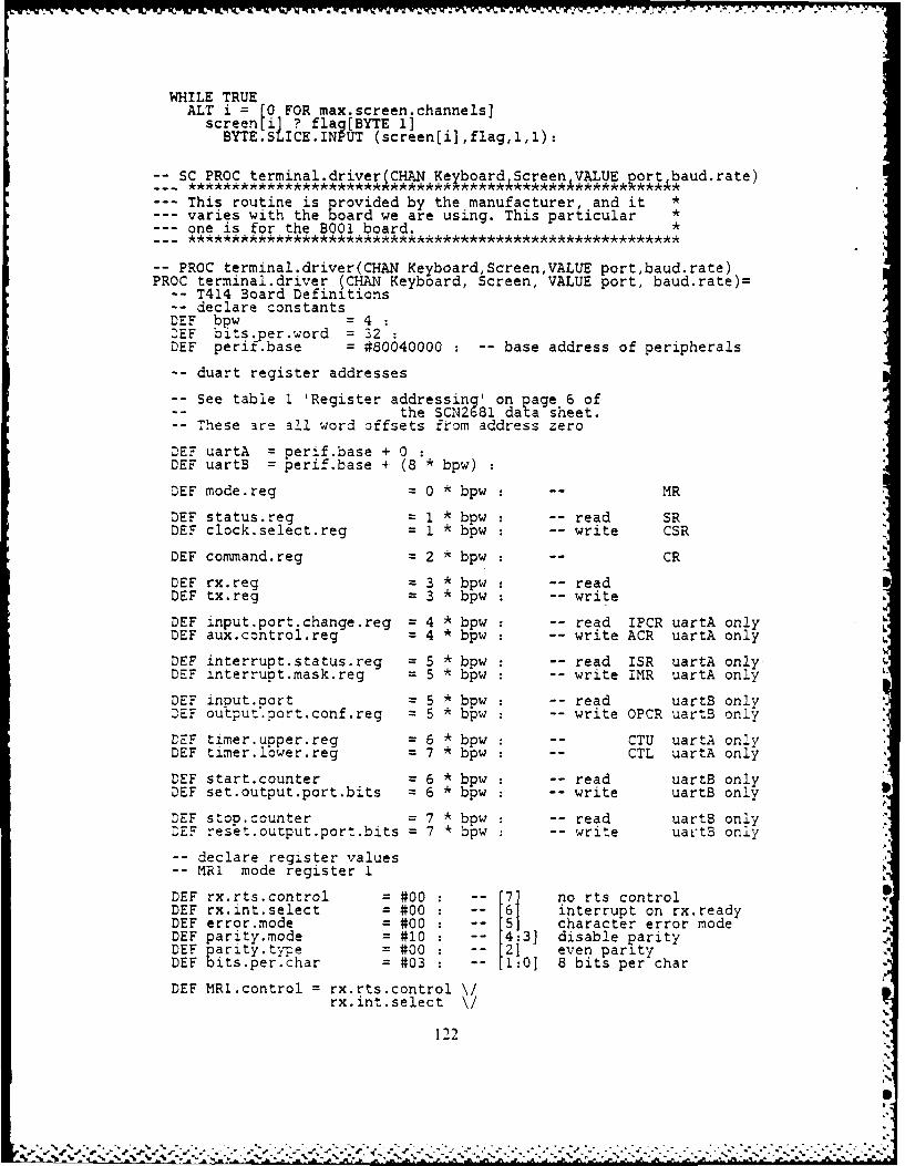
WHILE TRUEALT i = [0 FOR max.screen.channels]
screen[i] ? flag[BYTE 1]BYTE.SLICE.INPUT (screen[i],flag,1,1):
SC PROC terminal.driver(CHAN Keyboard Screen VALUE port baud.rate)
--- This routine is provided by the manufacturer, and it *varies with the board we are using. This particular *
--- one is for the B001 board. *
PROC terminal.driver(CHAN KeyboardScreenVALUE portbaud.rate)PROC terminal.driver (CHAN Keyboard, Screen, VALUE port, baud.rate)
PO T4i4 Board Definitions-- declare constantsDE bw =t 4DEF boits.per.word = 32DEF perif.base = #80040000 : -- base address of peripherals
-- duart register addresses
-- See table I 'Register addressing' on page 6 ofthe SCN2681 data sheet.
-- These are all word offsets from address zero
DEF uartA = perif.base + 0
DEF uartB = perif.base + (8 * bpw)
DEF mode.reg = 0 * bpw -- MR
DEF status.reg = 1 * bpw : -- read SRDEF clock.select.reg = 1 * bpw : -- write CSR
DEF command.reg = 2 * bpw : -- CR
DEF rx.reg = 3 * bpw -- readDEF tx.reg = 3 * bpw : -- write
DEF input.port.change.reg = 4 * bpw : -- read IPCR uartA onlyDEF aux.control.reg 4 * bpw : -- write ACR uartA only
DEF interrupt.status.reg = 5 * bpw : -- read ISR uartA onlyDEF interrupt.mask.reg 5 * bpw : -- write IMR uartA only
DEF input.port = 5 * bpw : -- read uartB onlyDEF outpuz.port.conf.reg = 5 * bpw : -- write OPCR uartB only
DEF timer.upper.reg = 6 * bpw : -- CTU uartA onlyDEF timer.lower.reg 7 * bpw : -- CTL uartA only
DEF start.counter = 6 * bpw : -- read uartB onlyDEF set.output.port.bits 6 * bpw : -- write uartB only
DEF stop.counter = 7 * bpw : -- read uartB onlyrEF reset.output.port.bits = 7 * bpw : -- write ualrtB only
-- declare register values-- MR1 mode register 1
DEE rx..rts.control = #00 ' -7] no rts controlDEF rx.int.select = #00 : -- '6] interrupt on rx.readyDEF error.mode = #00 : -- character error modeDEF parity.mode = #10 : -- 4:3] disable parityDEF parity.type = #00 : -- even parityDEF bits.per.char = #03 : -- 1:0] 8 bits per char
DEF MR1.control = rx.rts.control \/rx.int.select \/
122

error.modepari.ty.mode \
~its.per.char
-- MR2 mode register 2
DEF channel.mode = #00 : -- 7:6] normal channel modeDEF tx.trs.control = #00 : - [5] rts control not usedDEE cts.enable.tx = #00 [4 cts control not usedDEE stop.bit.length, = #07 : 13:0] 1.000 stop bits
DEF MR2.control = channel.mode \tx.trs.control.\cts.enable.tx \stop.bit.length
-- CR command register
DEE bit.seven = #00 : -- [7] not used must be zero
(- 6:4] misc comds never combined
DEE no.command = #00 :DEF reset.mr.ptr = #10 : -- make mode register point at IRIDEF reset..rx = #20:DEF reset.tx = #30 :pDEF reset.error = #40:DEE reset.break =#50DEE start.break = #60:DEF stop.break = #70:
DEE ensable.rx = #02 : 2-[3DEE diable.rx = 01 : 31 2DEE enable.tx = #04 : -[1]
DEE disable.tx = #08 : -[0]
-- SR status register
DEE received.break = #80 : -- 7DEE framing.error = #40 : 6DEE parity.error =#20 : 'DEE overrun.error = #10:DEE tx.empty = #08 : '3DEE tx.readY = #04 :-'DEE fifo.fu 1 = #02 : '1DEE rx.ready = #01 : L01
-OPCR output port configuration register
M-!ask this beast out before programming the timer
DEF OPCR.control = #00 -- [7:01 mask out output port
-ACR aux control register
DEE brg.set.select = #00 (- 7] select set 1 baud rates-- for CSRA
DEE counter.timer.mode =#00 : -[6:4] external counterDEE delta.ip3.0.int = #00 :-13:0] no bits in IPCR affect
-- in IMR [7]
DEE ACR.control = brg.set.selectcounter.timer.mode \delta.ip3.0.int
-IMR interrupt mask register
12.3
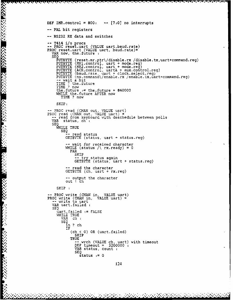
DEF IMR.control = #00: -- [7:0] no interrupts
-- PAL bit registers
-- RS232 RX data and switches
-- T414 i/o procs-- PROC reset.uart (VALUE uart,baud.rate)PROC reset.uart (VALUE uart, baud.rate)=
VAR now, the.futureSEQ
PUTBYTE (reset.mr.ptr\/disable.rx /disable.tx,uart+command.reg)PUTBYTE (MR1.control, uart + mode.reg)PUTBYTE (MR2.control, uart + mode.reg)PUTBYTE (ACR.control, uartA + aux.control.reg)PUTBYTE baud.rate, uart + clock.select.reg)PUTBYTE (no.command\/enable.rx /enable.tx,uart+command.reg).,--wait a bitTIME the.futureTIME ? nowthe.future := the.future + #40000WHILE the.future AFTER now
TIME ? now
SKIP:
-- PROC read (CHAN out, VALUE uart)PROC read CHAN out, VALUE uart) =
-- read from keyboard with deschedule between pollsVAR status, chSEILE TRUE
SEQ-- read statusGETBYTE (status, uart + status.reg)
-- wait for received characterWHILE (status /\ rx.ready) = 0
PARSKIP-- try status againGETBYTE (status, uart + status.reg)
-- read the characterGETBYTE (ch, uart + rx.reg)
-- output the characterout ! ch
SKIP :PROC write (CHAN in, VALUE uart)
PROC write (CHAN in, VALUE uart)
-- write to uartVAR uart.failedSEQ
uart.faiied := FALSEWHILE TRUE
VAR chSEQ
in ? chIF
(ch < 0) OR (uart.failed)SKIP
TRUE-- wrch (VALUE ch, uart) with timeoutDEF timeout = 3200000VAR status, countSEQ
status : 0
124
'.

count :=0WHILE ((status /\ tx.ready) = 0) AND (count < timeout)
8EETBYTE (status, uart + status.reg)count :=count + 1
IFcount = timeoutuart.failed :=FALSE --- TRUE
TRUEPUTBYTE (ch, uart + tx.reg)
SKIP
-main programVAR uartSEF
port =0
uart uartATRUE
uart :=uartBreset.uart (uart, baud.rate \/(baud.rate << 4))PAR
read (Keyboard, uart)write (Screen, uart)
SKIP
125

-- main body of the operating systemSEQ
-- receivin the routing tableroute.table 0 tO --- output link to transp #0route.table 1 t1 --- output link to transp #1route.table 2' t2 --- output link to transp #2route.table 3 = t3 --- output link to transp #3route.table 4 : t4 output link to transp #4route.table 5 = t5 output link to transp #5route.table 6 t6 --- output link to transp #6route.table 7 t7 --- output link to transp #7route.table 8 t8 --- output link to transp #8route.table 9 t9 --- output link to transp #9route.table I tl0 --- output link to transp #10route.table 11' til --- output link to transp #11route.table 12' t12 --- output link to transp #12route.table=3 output link to transp #13route.table[14 = t14 --- output link to transp #14route.table[IS. t15 output link to transp #15route.table L 16] t16 --- output link to transp #16route.table [171 t17 --- output link to transp #17
PARoutput.handlerinput.handler:erminal.driver(Keyboard,Screen,port,baud)screen.handler
1
S.
126"
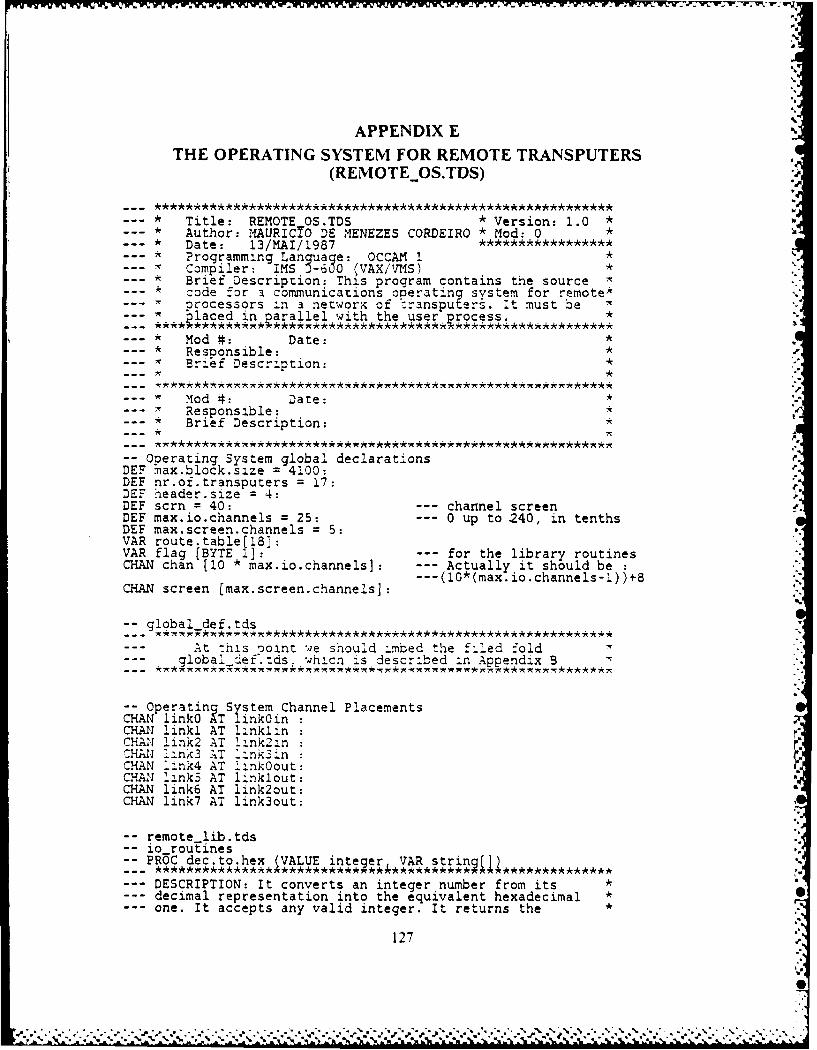
APPENDIX ETHE OPERATING SYSTEM FOR REMOTE TRANSPUTERS
(REMOTEOS.TDS)
* Title: REMOTE OS.TDS * Version: 1.0 ** Author: MAURICIO DE MENEZES CORDEIRO * Mod: 0 * *
* Date: 13/MAI/1987Programming Lanquage: OCCAM 1
* Compiler: IMS _600 (VAX/VMS) ,* Brief Description: This program contains the source *
code for a communications operating system for remote*processors in a network of wransputers. it must be "p laced in oarallel with the user-process. *
* Mod #: Date: ** Responsible: ** Brief Description: *
* od #: Date: *- Responsible: ,* Brief Description: *
-- Operating System global declarationsDEF rax.block.size = 4100:DEF nr.of.transputers = 17:DEF header.size = 4:DEF scrn = 40: --- channel screenDEF max.io.channels = 25: --- 0 up to 240, in tenthsDEF max.screen.channels = 5:VAR route.tablel18]:VAR flag [BYTE 1]: --- for the library routinesCHAN chan [10 * max.io.channels]: Actually it should be
---(10*(max.io.channels-1))+8CHAN screen [max.screen.channels]:
4.
-- global def.tds
At :his joint -4e should imbed the filed -old--- global def'.tds, whicn is described in Appendix B
-- Operating System Channel PlacementsCHAN linkO AT linkOinCHAN !inkl AT lInklinCHAN link2 AT link2in :CHAI 7ink3 AT L-nk3inCHAN Link4 AT 'ink0out:CHAN 7ink5 AT linklout:CHAN link6 AT link2out:CHAN link7 AT link3out:
-- remote lib.tds-- io-routines
-PROC dec.to.hex (VALUE inteier,*VAR strin4]
--- DESCRIPTION: It converts an integer number from its *--- decimal representation into the equivalent hexadecimal *
one. It accepts any valid integer. It returns the *
127

--- hexadecimal number stored in a string of 10 bytes long *where the leading zeros are preserved *It returns the following format: [size]#0000FFFF *USAGE: dec.to.hex(37182,hex.string) *REMARK: The BYTEr0] of the string carries its length *which is always 9, therefore it could be deleted, but *we decided to keep it *
PROC dec.to.hex (VALUE integer, VAR string []) =VAR first, order.of.digit, digitVAR number :DEF hex.char = "0123456789ABCDEF"SEfirst := TRUE
string rBY TE 01 : 9string BYTE 1]number := integerorder.of.digit := 9WHILE (number > 0) OR (first=TRUE)
SE~igit : number /\ #F
digit : hex.char [BYTE digit + 1]string [BYTE order.of.digit] := digitnumber := number >> 4order.of.digit := order.of.digit -first := FALSE
SEQ i = (2 FOR ;order.of.digit -string (BYTE i] ;= '0':
-PROC dec.to.ascii (VALUE inteper, VAR string
--- DESCRIPTION: It converts an integer number from its *decimal representation into the equivalent ASCII one. It *
--- accepts any valid integer number. it returns the ASCIInumber stored in a string of 12 bytes long, where the *
--- number is right justified and i as the ollowing *format: - 3 42 --- > 1-11 1 I 11 11 '1 I 113115141 21 *
1922937 ---> 1 11 11 11 1 .1191121121191131171USAGE: dec.to.ascii(-9873,ascii.string) *REMARK: The BYTE[O] of the string carries its length *which is always 11, therefore it could be eliminated, but*we decided to keep it. *
PROC dec.to.ascii (VALUE integer, VAR string [3) =VAR number :VAR order.of.digitDEF min.int = - 2147483648
SEQnumber : integerorder.of.digit :11istring [BYTE 0] 11IFnumber = min.int
-- taking care of the limit caseSEQstring BYTE 1 := 1-1string BYTE 2 : 121string BYTE 3 : '1'string BYTE 4 : '4'string BYTE 5 : 171string BYTE 6 : '4'string BYTE 7 : '8'string BYTE 8 : 131string BYTE 9 : '6'string BYTE 1 : '4'string BYTE 11 : 8
128 .
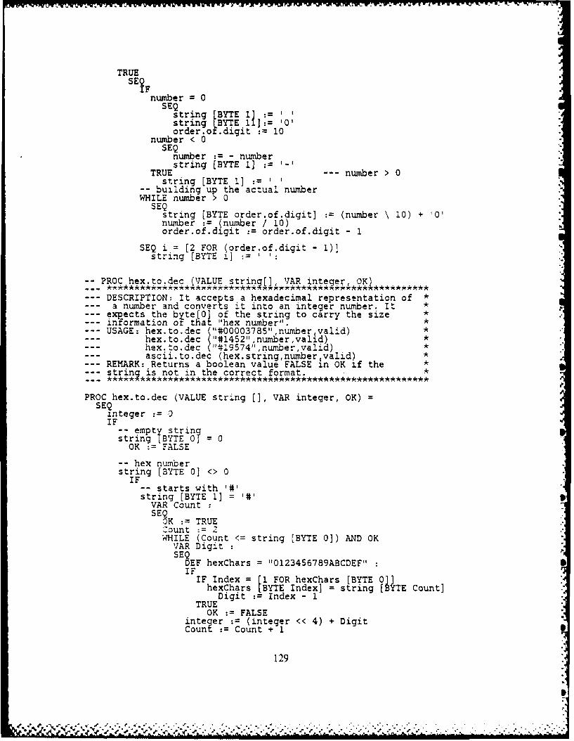
-WW V- Y -.- - -- -trI M- 'W S-'% -
TRUESETF
number = 0SEQ
string tBYTE 11string LBYTE 11 J: 0'order.o fdigit :10
number < 0SEQ
number :-number
TRUE srn [BT 11--number > 0st ring [BYTE 1]
-building up the actual numberWHILE number > 0
SEQstring [BYTE order.of.digit] := (number \1~0) + '0'number := (number / 10)order.of.digit :=order.of.digit - 1
SEQ i =[2 FOR (order~of.digit - 1)]string (BYTE i]
PRO he~todec(VAUEstrin~jU VAR integer, OKI,
--DESCRIPTION: it accepts a hexadecimal representation of*--a number and converts it into an inte ger number. It *--expects the byte[0] of the string to c arry the size*--information ot that "hex number".*--USAGE: hex.to.dec ('"*000037a5" ,numberqvalid)*-- hex.to.dec ("1#1452",number,valid)*-- hex. to.dec ("#19574",number,valid)*-- ascii.to.dec (hex string,number valid)*--REMARK: Returns a boolean value FALSE In OK if the*
strinq is not in the correct format.*
PROC hex.to.dec (VALUE stri-ng [ VAR integer, OK)=SEQ
integer := 0IF
- emty stringstring BYTE 0 0OK := FALSE
-- hex numberstring [BYTE 0] <> 0IF
-starts with 1#1string [BYTE 1] = 1#1VAR CountSEQ
OK := TRUEZount :=WHILE (Count <= string [BYTE 0]) AND OK
VAR Digit:SEQ
DEF hexChars = "10123456789ABCDEF":IFIF Index = [1 FOR hexChars [BYTE 0]]hexChars[ BYTE Index] = string [BYE Count]TREDigit := Index - 1
OK :FALSEinteger :(integer << 4) + DigitCount Count + 1
129
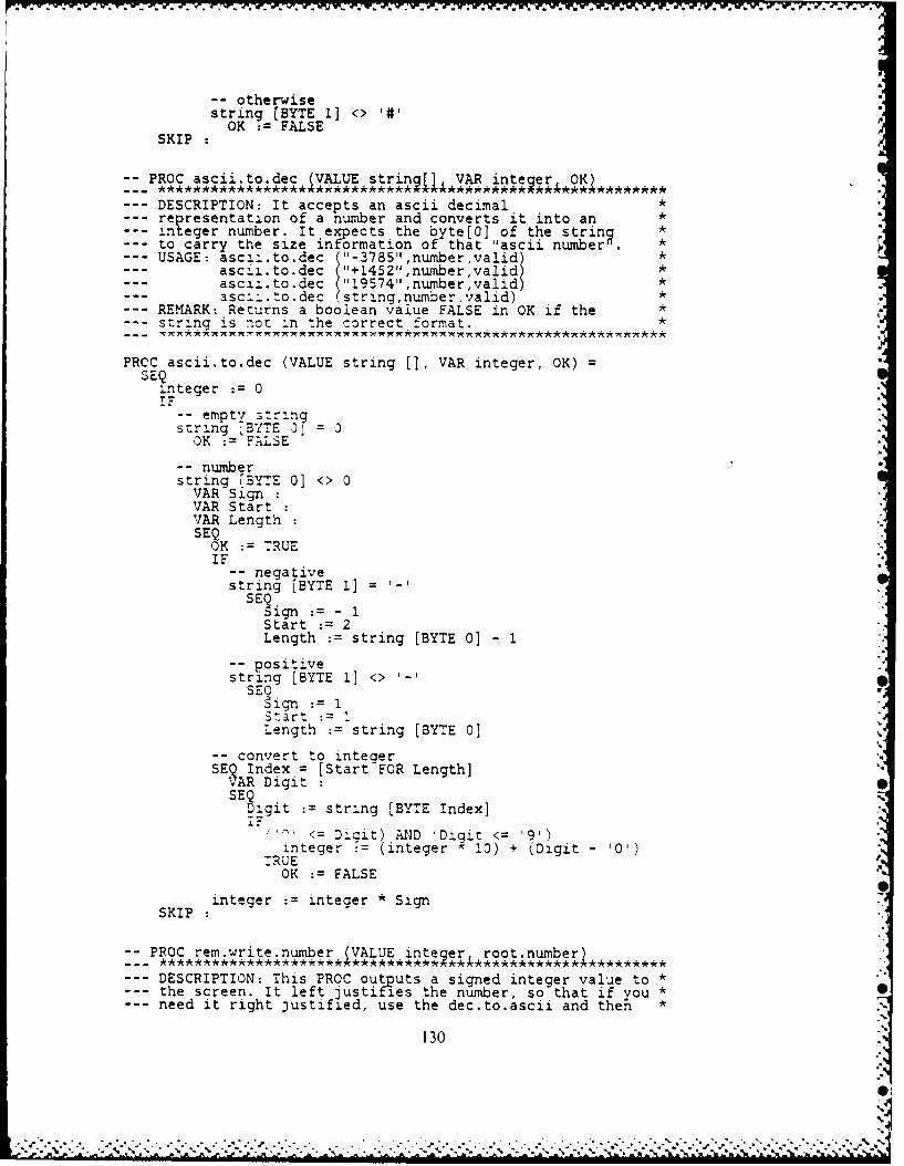
-- otherwisestring [BYTE 1] <> 1#1OK := FALSE
SKIP :
-- PROC ascii.to.dec (VALUE strinq[], VAR inte er, OKI * *._. **********************************************
--- DESCRIPTION: It accepts an ascii decimal *re resentation of a number and converts it into an *integer number. It expects the byte[O] of the strinq *to carry the size information of that "ascii number n . *--USAGE: asciitodc ("-3785",number,valid)
ascii.to.dec ("+1452",number,valid) *--- ascii.to.dec ("19574",number,valid) *
ascii.to.dec (string,number valid) *REMARK: Returns a boolean value FALSE in OK if the *strlng is not in the correct format. *
PRCC ascii.to.dec (VALUE string [3, VAR integer, OK) =SEQ
integer := 0iF-- empty str :ngstring 7BYTE 0? = 3
OK := FALSE
-- numberstring [BYTE 01 <> 0
VAR SignVAR StartVAR LengthSEQ
OK : TRUEIF "-- negative
string [BYTE 1] =SE~ign
:= - 1Start : 2Length := string [BYTE 0] - 1
-- positivestring [BYTE 1] <> '-'
SE i n : I
Start := .Length := string [BYTE 0]
-- convert to integerSEQ Index = [Start FOR Length]VAR DigitSEQ
_igit := string [BYTE Index]
<= Digit) AND i'Digit <= '9')integer := (integer x 10) + (Digit - '0')
TRUEOK := FALSE
integer := integer * SignSKIP
-- PROC rem.write.number (VALUE inteqer root.number
--- DESCRIPTION: This PROC outputs a signed integer value to *--- the screen. It left justifies the number, so that if you *
need it right justified, use the dec.to.ascii and then *
130
.+ -- .- -. - ..+ . . ,- . , --, - .. . , .. '. -. .- ,- . " . . . " " " '- ", ". ". +. -, -, ", -, ", ", -, 0"
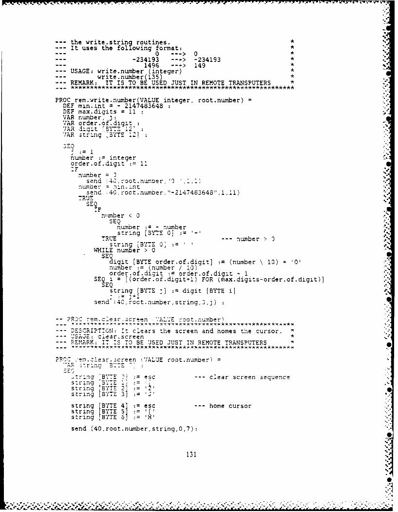
the write.strinq routines.--- It uses the folowing format: *
0 --- >0 *-234193 --- > -234193 *
1496 ---> 149 *USAGE: write.number (integer) *
--- write.number(135)--- REMARK: IT IS TO BE USED JUST IN REMOTE TRANSPUTERS *
PROC rem.write.number (VALUE integer, root.number) 'DEF min.int = - 2147483648DEF max.digits = 11VAR number, 3:VAR order.of.digitVAR digit BYTZ 121"VAR string-'BYTE .21
number integerorder.of.digit := 1i__-
number =send 40,root.number, '0
number = ,nn.intsend 40,root.number."-2147483648",i,1l)
TRUESE9 :.Fnunber < 0
SEQnumber - numberstring [BYTE 0] =
TRUE --- number > 0string [BYTE 0]
WHILE number > 0
SEsigit [BYTE order.of.digit] := (number \ 10) + '0'number := (number / 10)order.of.digit := order.of.digit - 1
SEi = [(order.of.digit+l) FOR (max.digits-order.of.digit)]EQ.
string [BYTE j] := digit [BYTE i]
send (40,root. number,string,oj)
- PROC rem.clear.screen "ALUE root.number , .
DESCRIPT:CON: it clears the screen and homes thle cursor.uSAGE: clear.screen *REMARK: IT iS TO BE USED JUST IN REMOTE TRANSPUTERS *
PRO- :em.zlear.screen (VALUE root.number) ="A -r~nc -BT. "
_;trina "BYTE i esc --- clear screen sequencestring BYTE
string BYT- 3 'j'
string [BYTE 4 esc --- home cursorstring BYTE 5 ] Pstring BYTE 6 =H"
send (40,root.number, string,0,7):
131
- , . - - * ' r, . -- -- .. -. f --. -

:PROC rem. os cursor*IAU line column root numberDESCRIPTION: Positions the cursor in a specified line and*column. We have used the ANSI escape sequence*ESC jLine;Column H.*USAGE: pos.cursor (8,30)
--REMARKl: Valid values for line are 0 up to 24*Valid values for column are 0 up to 80*
--REMARK2: Values out of the above range will cause*unpredictable results.*
--REMARK3: 1T 1S TO BE USED JUST IN REMOTE TRANSPUTERS
PROC rem.pos.cursor_(VALUE line, column, root.number)VAR string BYE81:VAR x 'BYTE Z!, Y BYTE 2]1
,,line < 1,3 ) AND ( line ~JSEQ ~YE :'
y BYTE 1] := line + #30(line >= !0) AND (li.ne <= 24)
SEQy BYTE 0]:(line/1.O' + #3 0Y LBY- 11 ,!~inle\1J) + 30
:RUESKIP
IF, column <~ 10) AND "column >= 0)
SEQ
" [BYTE 1 : column + #30(column >= 10) AND (column <= 80)
SE [BYTE 0 : "column, 10, + #30
" BYT 1]: column\ 10) + #30TRUE
SKIPstring BYTE 0] escstri.ng :BYTE 1 Istring BYTE 2' y BYTE 01string BYTE 3. BYTE 11string BYTE 4s tring BYTE 5 x BYTE 01string BYTE 6'~ BYTE ljstlring BYTE 71 .send Oro~unrsrn,,~
-PROC rem.new.line (VALUE number 'oot number)
--DESCRIPTION: It will skip as many lines as specified in*its parameters list.USAGE: new.line(4)*RE:!ARKl: Negative numbers will not give any new lines.*
- -- RE::ARK2: ;7 TO 30E USED :UST :N~ 7RENOTE :RAN4SPUTERS
PROC rem.new.line (VALUE number, root.number)VAR string [BYTE 2]:SEQ
string[ BYTE 0] :crstring [ BYTE 1] :lfSEQ i = [0 FOR number]
send (40, root.number,string,0,2):
~PROC rem s~ace~iAU number root.number
132
%S
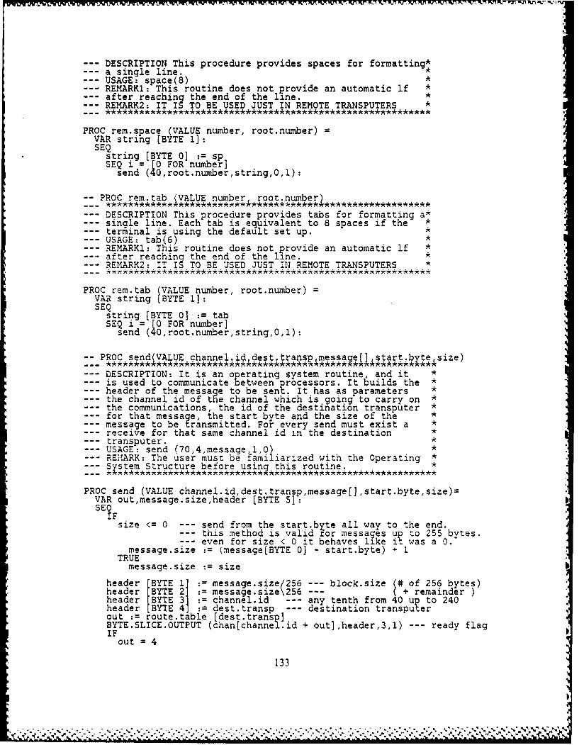
-%K 1 %n VVi
--- DESCRIPTION This procedure provides spaces for formatting*a single line. *
--- USAGE: space(S) *REMARK1: This routine does not provide an automatic if *after reaching the end of the line. *REMARK2: IT IS TO BE USED JUST IN REMOTE TRANSPUTERS *
PROC rem.space (VALUE number, root.number) -
VAR string [BYTE 1]:SEQ
string [BYTE 0] := spSEQ i = [0 FOR number]
send (40,root.numberstring,0,1):
-- PROC rem.tab (VALUE number roor.number)
--- DESCRIPTION This procedure provides tabs for formatting a-single line. Each tab is equivalent to 8 spaces if the *
--- terminal is using the default set up. *--- USAGE: tab(6) *
REMARKi: This routine does not provide an automatic lf *after reaching the end of the line. *RE ARK2: IT I TO BE USED JUST IN REMOTE TRANSPUTERS *
PROC rem.tab (VALUE number, root.number) =VAR string BYTE 1]:SEQ
string [BYTE 0] := tabSEQ i = [0 FOR number]
send (40,root.number,string,0,1):
:: PROC send(VALUE channel iddest.transR.messae(]. start.bytesize)
--- DESCRIPTION: It is an operating system routine, and it *is used to communicate between processors. It builds the *header of the message to be sent. It has as parameters *the channel id of t e channel which is going to carry on *the communications, the id of the destination transputer *for that message, the start byte and the size of the *message to be transmitted. For every send must exist a *receive for that same channel id in the destination *transputer. *USAGE: send (70,4,message,1,0) *REMARK: The user must be familiarized with the Operating *
--- System Structure before using this routine. *
PROC send (VALUE channel.id,dest.transp,message[],start.byte,size)=VAR out,message.size,header [BYTE 5]:SEF
size <= 0 --- send from the start.byte all way to the end.--- this method is valid tor messages up to 255 bytes.--- even for size < 0 it behaves like it was a 0.
message.size : (message[BYTE 0] - start.byte) + 1TRUE
message.size : size
header (BYTE 1] : message.size 256 --- block.size (# of 256 bytes)header "BYTE 21 : message.size\256 --- ( + remainderheader "BYTE 3] := channel.id --- any tenth from 40 up to 240header [BYTE 4] : dest.transp --- destination transputerout := route.table [dest.transp]BYTE.SLICE.OUTPUT (chan[channel.id + out],header,3,1) --- ready flagIF
out 4
133
V ,%
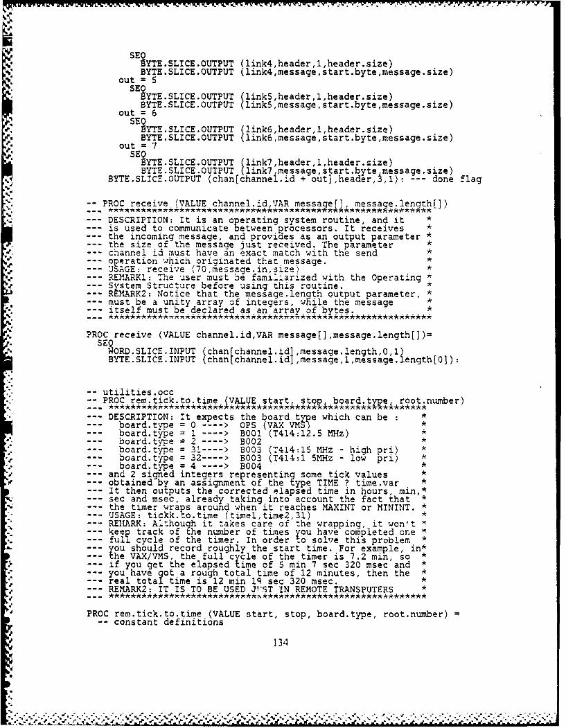
SE YTE.SLICE.OUTPUT (link4,header,l,header.size)
BYTE.SLICE.OUTPUT (link4,message,start.byte,message.size)out = 5
SE YTE.SLICE.OUTPUT link5,header,1,header.size)
BYTE.SLICE.OUTPUT link5,message,start.byte,message.size)out = 6
SEQBYTE.SLICE.OUTPUT (link6,header,l,header.size)BYTE.SLICE.OUTPUT (link6,message,start.byte,message.size)
out = 7SEQBYTE.SLICE.OUTPUT (link7,header,l,header.size)BYTE.SLICE.OUTPUT (link7 message,start.bytemessage.size)
BYTE.SLICF.OUTPUT (chan[channei.id + out],header,3,1): --- done flag
PROC receive (VALUE channel.idVAR message[], message.length[])
--- DESCRIPTION: It is an operating system routine, and it *is used to communicate between processors. It receives *
--- the incoming message, and provides as an output parameter *the size of the message just received. The parameter *
--- channel id must have an exact match with the send *--- 0 eration which oriainated that message.--- UAGE: receive (7Om-essage.in,size)--- REIMARKI: The user must be familiarized with the Operating *
System Structure before using this routine. *REMARK2: Notice that the message.length output parameter, *must be a unity array of integers, while the message *itself must be declared as an array of btes. *
PROC receive (VALUE channel.id,VAR message[],message.length[])=SE ORD.SLICE.INPUT (chan[channel.id ,message.length,0,1 ength[0 :
BYTE.SLICE.INPUT (chantchannel.id ,messagel,message. ])
-- utilities.occ-- PROC rem.tick.to.time (VALUE start stop board.tne root.number)...- ******,************** ************* ********* *,*******
--- DESCRIPTION: It expects the board type which can be : *board.type = 0 ----> OPS (VAX VMS) *board.type = 1 ---- > B001 (T414:12.5 MHz)board.type = 2 ---- > B002
--- board. type = 31 ---- > B003 (1414:15 MHz - high pri) *--- board.type = 32 ---- > B003 (T414:1 5MHz - low pri) *--- board.type = 4 ---- > B004 *
and 2 signed integers representing some tick values *obtained by an assignment of the type TIME ? time.var *It then outputs the corrected elapsed time in hours, min,*sec and msec, already taking into account the fact that *
--- the timer wraps around when it reaches MAXINT or MININT. *- USAGE: tickk.to.time (timel,time2,31) *REMARK: Although it takes care of the wrapping, it won't Wkeep track of the number of times you have completed one *full cycle of the timer. In order to solve this problem *you should record roughly the start time. For example, in*the VAX/VMS, the full cycle of the timer is 7.2 min, so *if you get the elapsed time of 5 min 7 sec 320 msec and *you have got a rough total time of 12 minutes, then the *
--- real total time is 12 min i sec 320 msec. *--- REMARK2: IT IS TO BE USED JT'ST IN REMOTE TRANSPUTERS *
PROC rem.tick.to.time (VALUE start, stop, board.type, root.number) =-- constant definitions
134
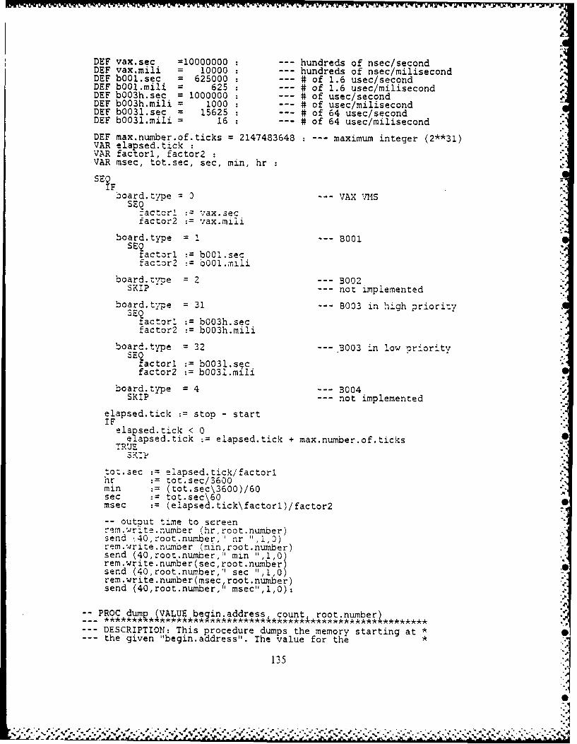
DEF vax.sec =10000000 . - hundreds of nsec/secondDEF vax.mili = 10000 . - hundreds of nsec/miljsecondpDEF b001.sec = 625000 : # of 1.6 usec/secondDEF bOO1.milj = 625 : # of 1.6 usec/milisecondDEF bQO3h.sec = 1000000 : # of usec/secondDEF bOO3h.mili = 1000 * of usec/milisecondDEF b0031.sec = 15625 : # of 64 usec/secondDEF b0031.mili = 16 . # of 64 usec/milisecond
DEF max.number.of.ticks = 2147483648 -- maximum integer (2**31)VAR elapsed.tickVAR factori, factor2VAR msec, tot.sec, sec, min, hr
SEF
!Doard. type --- VAX VMS
:actor'L vax. se cfactor5 v.axnili
board.type =1 -- BOOl
S'actorl bOO1.secfac:tor2 b001..nlii
board.tv--e =2 -- 3002SKI-P not implemented
board.type =31 -- B003 in high prioritySE!actorl b0O3h.sec
factor2 b0O3h.mili
board.type =32 -- 5003 in l.ow -rioritv
?actor1 b0031.secfactor2 b0031.mi
board type =4 -- 3004SKIP - not implemented
elapsed.tick stop - startIF lasdtc<0
elapsed tick :=elapsed.tick + max.nuxnber.of.ticksTRUE
tot.sec elapsed.tick/factorlhr :tot.sec/3600min (tot.sec\3600)/60sec tot sec\ 6msec (elapsed tick\factorl)/factor27
-- output time to screenrem.write.number (hr,root.number)send .,40,root.number," r ",,rem.write.number (min,root.number)send (40,root.number,'1 min 1,0)rem-write.nuxnber(secroot.numnber)send (40,root.number,I sec 11,1,0)rem.write.number(msec,rotnubrsend (40,root.number," msec",1,.0):
PRO dm*VLEbegin.address count root.number~
--DESCRIPTION: This procedure dumps the memory starting at*--the given "begin.address". The value for the*
135
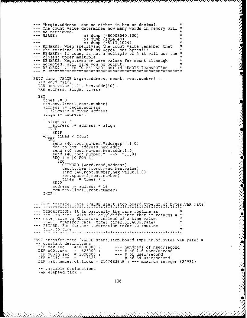
7%
--- "begin.address" can be either in hex or decimal. *--- The count value determines how many words in memory will *--- be retrieved. *--- USAGE: a) dump (#80003540,100) *
b dump (1024,48) *c) dump (-5113,1024) *
--- REMARK1: When specifying the count value remember that *--- the retrieval is done by words, not bytes!!! *,--- REMARK2: If count is not a multiple or 4 it will use the * '.
--- closest upper multiple. *--- REr2RK3: Negatives or zero values for count although *
Saccepted, wIll give you no output. *REIARK4: IT IS TO BE USED JUST IN REMOTE TRANSPUTERS *
?R:C 4uma VAL'E begin.address, count, root.number)';AR c d. r-ad:':A-, e a .ue01, hex.addr[10]:An adress, al.an, z:mes:
SEQ:zmes : 0rem.new.line(l,root.number)address := beain.address
a-, nin a aiven address-i: aress',4
3~Ol <> 2aadress : address - align
TRUESKI?
WHILE times < countSEC
send (40, root.number, "address 11,1,0)iec.to.hex 'address,hex.addr)send 40,root.number,hex.addr, 1,0)send40,root.number," -- > ",1,0)SE Q = ECR 410
GETWORD (word.read,address)dec.to.hex (word.read,hex.value).;end (40,root.number,hex.value,l,0)rem.space(2,root.number)times := times + 1
SKIPaddress := address - 16rem. ne,; . Iine( 1, root. number)
?P.CC transfer.rate (VALUE startstopboard. tveRnr.of.bytesVAR rate)
--- :ESCR:PT:01: It is basically the same routine as *-ick.to.time, with the only difference that it returns ar :e %'alue -n Xbits/sec instead of a time value.3AGE: transfer.rate t-mel,time2,31,4096,rate)---REYARK: zr :~irter :nformaticn refer to routine
--- :: to. .eme
?RCC transfer.rate (VALUE start,stop,board.type,nr.of.bytes,VAR rate)-- ccnstanz definitionsDEF vax.sec =10000000 : --- hundreds of nsec/second:EF b001.sec = 625000 : --- # of 1.6 usec/secondDEE b003h.sec = 1000000 : --- # of usec/second:EF b031.sec = 15625 : --- # of 64 usec/secondDEF max.number.of.ticks = 2147483648 : --- maximum integer (2**31)
-- variable declarationsVAR e.apsed.tick
136
-. .- . . .. . . . -. " .
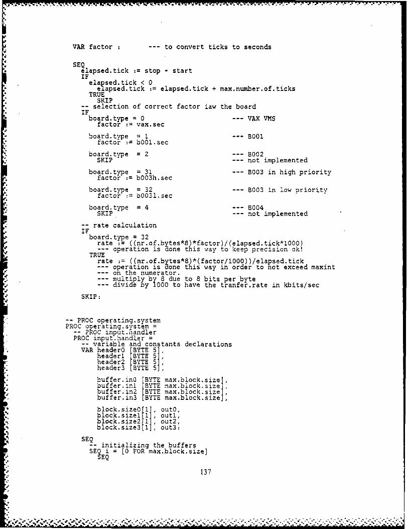
VAR factor -- to convert ticks to seconds
SEQelapsed.tick :=stop -start
IFelapsed.tick < 0
elapsed.tick :=elapsed.tick + max.number.of.ticksTRUE
SKIP-selection of correct factor jaw the board
board type = 0 -- VAX VMSfactor :=vax.sec
board. type =1 - B001factor :=b001.sec
board.type = 2 -- B002SKIP -- not implemented
board type = 31 -- B003 in high priorityfactor := bOO3h.sec
board.type = 32 -- B003 in low priorityfactor :=b0031.sec
board.type = 4 -- B004SKIP. - -- not implemented
-rate calculationIFboard. type =32
rate := ((nr.of b~tes*8 *factor)/(elapsed.tick*10OO)--ooeration is done this way to keep precision ok!
TRUErate :=((nr.of.bytes*8) *(factor/1000))/elapsed.tick--operation is done this way in order to not exceed maxint--on the numerator.--multiply by 8 due to 8 bits per byte--dividby10tohvte tranfer.rate in kbits/sec
d SKIP:
-PROC operating.systemPROC onerating-system =
?R POC inout.handlerPROC input.handler=
-variable and constants declarationsVAR headerO BYTE 5]'
headeri (BYTE 5]header2 [BYTE 5]header3 [BYTE 5]
buffer.inO (BYTE max.block size]buffer.inl [BYTE max.block~si4ze]buffer.in2 [BYTE max.block.size]buffer.in3 BYTE max.block.sizeJ,
block.size outo,block.sizel1 outl,block.size2 1 ,out2,
blcksze out3:
SE- initializing the buffersSE i = 0 FOR max.block.size]
137
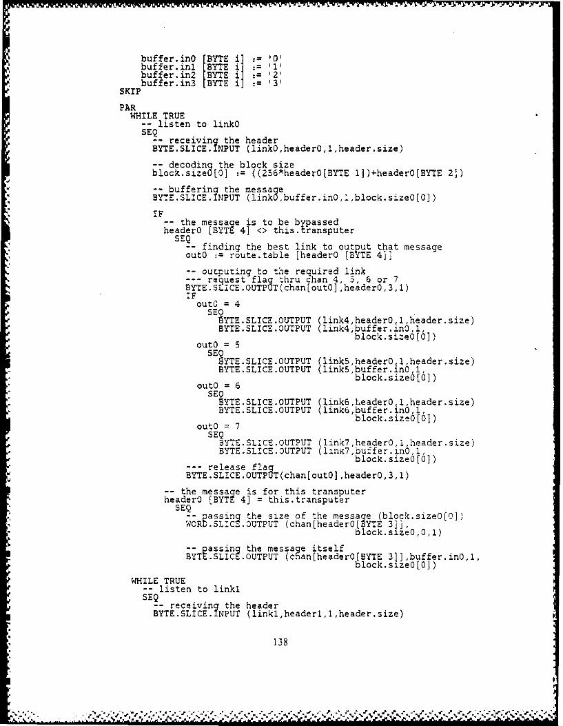
buffer inO [BYTE ii 0'buffer~inl [BYTE i 11buffer.in2 [BYTE i] '2'
SKPbuffer.in3 [BYTE i] '3'
PARWHILE TRUE
-- listen to linkOSEQ
-- receiving the headerBYTE.SLICE. IPUT (linkO,headerO,l,header.size)
-- decoding the block sizeblock.size0 [0] :=((256*header0[BYTE 1])+header0[BYTE 2]j)
-- buffering the messageBYTE.SLICE. I PUT (linkO buffer.in0,1,block.size0[0])
IF__ the message is to be bypassedheaderO [BYTE 4] <> this. transputer
SEfinding the best link to output that messageoutO :=route.table [headerO [BYTE 4]]
-outputing to the required linkrequest flag thru chan 4, 3, 6 or 7
BYTE.SLICE.OUTPUT(chan [outO] ,headerO,3,l)
outO = 4SEQ
BYTE.SLICE.OUTPUT (link4,header0 1 ,header .size)BYTE.SLICE.0UTPUT (link4,buffer.in0,1,
block. sizea[01)outO = 5
SEQBYTE.SLICE.OUTPUT link5,header04 1,header.size)
BYTESLIC.OUTUTlink5,buffer.a1nO,1,
outo= 6SEQ
BYTE .SLICE OUTPUT (link6 ,header0 1, header.size)BYTE.SLICE.OUTPUT (link6,buffer.In0,l,
block. size [0] )outO =7
SEQBYTE.SLICE.OUTPUT (link7,header0,1,header.size)BYTE.SLICE.OUTPUT (link7,buffer.in0,1,
--release fla block.size0(0])BYTE.SLICE.OUTPgT(chan[out0] ,headerO,3,1)
-the message Is fo r this transputerheaderO [BYTE 4] = this.transputer
--Q passin5 the size of the message (block.sizeO[C])WORD .SLIC.OUTPUT (chan[header0[BYTE 3]],
block. saze0 ,0, 1)
-- assing the message itselfBYTE .SLIC~ -OUTPUT (chan[headerO[BYTE 31],buffer.inO,1,
block. saze [0])
WHILE TRUE-- listen to linklSEQ
-- receiving the headerBYTE.SLICE. INPUT (linkl,headerl,l,header.size)
138

-decoding the block Sizeblock.sizel [0] :=((256 * headerl[BYTE 1])+headerl[BYTE 2])
-buffering the messayeBYTE.SLICE. INPUT (linkl buffer.inl,l1, block.sizel(Ol)
IF-- the message is to be b~ assedheaderi [BYTE. 4] <> this.transputer%
S-Q finding the best link to outp ut that message%outi : route.table [headeri [BYTE 4]]
-- outputing to the required linkrequest flag thru chari 14, 15, 16 or 17
BYT E.-SLICE.OUTPUJT(chan( 1O+outl] ,headerl,3,4)iF
outl = 4BYTESLIC.OUTUT link4,headerl 1 ,header. size),BYTESLIC.OUTUT link4,buffer.i.n11I
out! = 5 lcsie[]
S EPBYTE.SLICE.OUTPUT (link5,headerl.1.h-eader.3:ze)BYTE.SLICE.OUTPUT (l1inkS.buffer...nl,l.
6lock. sizel,,0 I)outi 6
SEQBYTE.SLICE.QUTPUT (link6,header1,1,header.s~ze)BYTE.SLICE.OUTPUT (link6.buffer.in1,l,
block.sizel[O])outl 7
SEP3YTE.SLICE.OUTPUT (link7 ,headerI~,Iheader..1ze-)BYTE.SLICE.OUTPUT (link7,buffer.i.nl,l,
--release flag block.sizel(O])BYTE.SLICE.OUTPUT(chan[ lO+outl] ,headerl,3,4)
-the message is for this transputerheaderi [BYTE 41 = this.transputer
SEQ-- passin5 the size of the message (block.sizel[O])WORD.SLICE.OUTPUT (chan[headerl [BYTE 3]]
block.sizel,Q,1)
-- zoassin2 the message itselfBYTt.SLIC .OUTPUT cnan~headerl [BYTE 3]] ,buffer.inl,
l,block.sizel[0])
WHILE TRUE-- listen to link2SEQ
-- receiving the headerBYTE.SLICE. .NPUT (link2,header2,l,header.size)
-- decoding the block sizeblock.size2 [0] := ((256 * header2[BYTE 1])+header2[BYTE 2])
-- buffering the messa aeBYTE.SLICE. INPUT (link2 ,buffer.in2,l,block.size2[0])
IF__ the message is to be brpassedheader2 [BYTE 4] <this. r ansputer
SE- finding the best link to output that messageout2 route.table [header2 [B YTE 4]]
139
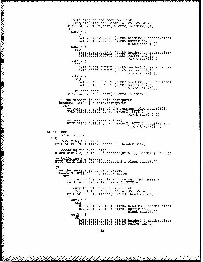
-outputing to the required linkrequest flag thru chan 24, 25, 26 or 27
BYTE.SLICE.OUTPUT(chan [20+out2] ,header2,3,1)
out2 =5SE YTE.SLICE.OUTPUT flink5 ,header2 ,l,header.size)BYTE.SLICE.OUTPUT link4,buffer. n2,1,
block. size2 [0])out2 =6
SEQBYTE.SLICE OUTPUT (link6 header2 i,header.size)BYTE.SLICE.OUTPUT (lznkbuffer.:ln2 1,
out2 = 6 lock.size 161)
SEQBYTE.SLICE.OUTPUT (link7 ,header2 ,1,header.s-,ze)BYTE.SLICE.OUTPUT (link6,buffer.in2,1,
re~ese 3T~hanblock-size2[0J1)
heade 2 =BT 4]7 ti~tasuSEQ
-pasigthe.sLize.of the (ln7mesaer2(bJhockr~size2])WOR .LIE .SLUTPPU channheader2 FBTE 3]]
e7 1Cblock.size2 ,0, )
-- assinc h io the message tselfie20]
BYTt.SLICS.OUTPUT cnan~header2 [BYTE 3]] ,buffer.in2,l,block.size2(o])
WHILE TRUE-listen to link3
-receiving the headerBYTE.SLICE. INPUT (link3,header3,1,header.size)
-decoding the block sizeblock.size3[01 := ((256 * header3[BYTE lD)+header3[BYTE 21)
-- bufferina the messa eaBYTE.SL:CE.INPUT (l'ink'-,buffer.in3,,block.sze3II01)
I-- the message is to be b yp assedheader3 [BYTE 4] <> this. tr-ansputer
SEQ_-finding the best link to output that message
out3 ;=route.table [header3 (BYTE 4]]
-outputing to the required link--request flag thru chan 34, 35, 36 or 37
BYTE.SLICE.OUTPOT(chan [30+out3] ,header3,3,l)IF
out3 = 4SE SYTE.SLICE.OUTPUT ( link4,header3,1,header.size)
BYTE.SLICE.OUTPUT (link4,buffer.in3,1,
out3 = 5block.size3[0])
SE YTE.SLICE.OUTPUT link5,header3 1, heade r.size)BYTE.SLICE.OUTPUT link5,buffer.in3,1,
140

out3 =6 block.size3jo])
SEYT~E -SLICE-OUTPUT (link6 ,header3(l,header.size)
BYTE. SLICE. OUTPUT (link6 ,e. in3, 1,
out3 =7block.size3[O])SEQBYTE.SLICE.OUTPUT (ink7,header3,l,header.size)BYTE.SLICE.OUTPUT (lirk7,buffer. n3,1,
--release fla block.size3[O])BYTE.SLICE.OUTP T(chanI3O+out3] ,header3,3,I)
-the message is for this tr-ansputerheader3 [BYTE 4] = this.transputer
SEQ-- assincr the size of the message (block.size3'01
WORfl.SLIC9.OUTPUT (chan[header3b BYTE 3]],o~ck.size3,0,1)
-passing 'the message itselfBYTE .SLICE .OUTPUT (chan[header3 [BYTE 3]],buffer.in3,
l,block.siie3[]))
-PROC output.handlerPROC output.handler =
-local variable declarationsVAR flag4 [BYTE 2]:VAR flag5 tBYTE 21:VAR flag6 [BYTE 2]:VAR flag7 [BYTE 2:
?ARWHILE TRUE
ALT i = R0 FOR max.io.channels]chan [(10*i) +4] ? flag4 [BYTE 0]-- for link4
BYTE.SLICE.INPUT (chan [(10*1) +4],flag4,0,l)WHILE TRUEALT j = [0 FOR max.io.channels)
chan [(10*j) +5]U? flag5 [BYTE 0] -- for link5BYTE SLICE.INPUT (chan [(l0*j) --5],flag5,0,1)
WHILE TRUEALT k = 0 FOR max.io.channels]
chan [(l0*k) +61 ? flag6 [BYTE 0] for link6BYTE SLICE.INPUT (chan [(l0*k) +6],flag6,0,l)
W4HILE TRUEALT 1 = [0 FOR max.io.channels]
chan f (10*1) +7] ? flag7 [BYTE 0] -- for link7BYTE.SLICE.INPUT (chan [(10*1) +7j',flag7,O,1):
141
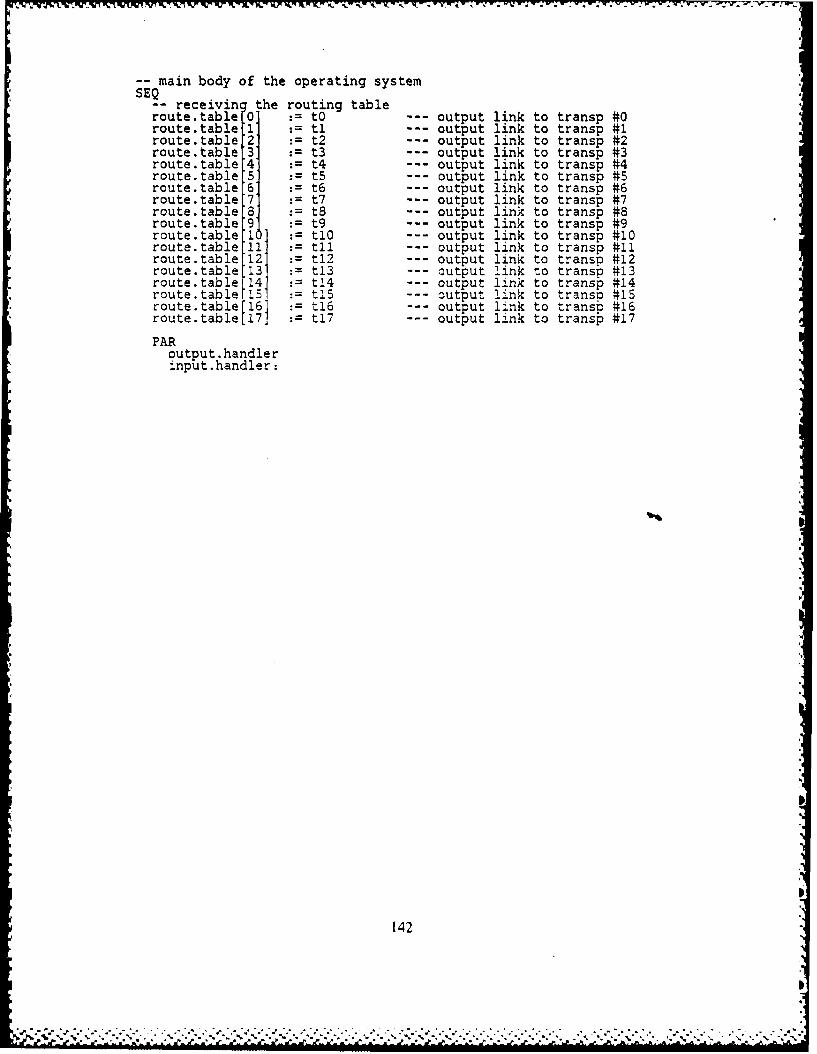
-% I W
-- main body of the operating system-- receivin the routing tableroute.table 0' to --- output link to transp #0route.table 1 : t1 --- output link to transp #1route.table '2 t2 --- output link to transp #2route.table :3 t --- output link to transp #3route.table :4 t4 output link to transp #4route.table 5 = t5 --- output link to transp #5route.table 6 = t6 --- output link to transp #6route.table 7 : t7 --- output link to transp #7route.table S' t0 --- output link to transp #8route.table 9' t9 --- output link to transp #9route.table 1 : t1- output link to transp #10route.table 11' t1l --- output link to transp #11route.table 12 : t12 --- output link to transp #12route.table 13 : t13 --- output link to transp #13route.table 14' t14 --- output link to transp #14route.table 15 : t1 --- output link to transp #15route.table [161 t1U6 -- output link to transp- #16route.table [17] Ut7 -- output link to transp #17
PARoutput.handlerinput.handler:
142
". A -ft. 'a ,a a. - .. ,.*. -. . , . , . . . . - .. ., .,.-... .. . . .- . . . . . , .. . - . - .. , - -

V.
APPENDIX F
THE EVALUATION PROGRAM FOR THE OPERATING SYSTEM(EVALOS.TDS)
-- PROGRAM os.evaluation-- os.evaluation-- SC PROC hostproc-- PROC hostproc(CHAN A,B,C,D,E,F,G,H,VALUE this.transputer, route.table)PROC hostproc(CHAN A,B,C,DE,F,G,H,
VALUE this .transputer,t0,tl.c2,t3,t4,t5,t6,t7,t8, t9,
-- root os.tds
--- In this alace should be imbedded the filed fold * S--- ROOTOS."DS, which contains the source code of the *
-- eratina system tor the root transouter. *:ts fully ocumented in Aum endix AZ-
-- PROC user.interfacePROC user.interface =
-- constant and variable declarationsDEF sizetable = TABLE [ 1, 2, 4, 8, 16, 32, 64, 128, 256,
512, 1024, 1280, 2048, 4096 ]:DEF nr.of.sizes = 14: --- # of entries in the above tableDEF naxblock.size = 4096: --- max from the above tableVAR bufferO BYTE maxblock.size + 11
bufferl BYTE maxblock.size + 11, pbuffer2 BYTE maxblock.size + 1]buffer3 BYTE maxblock.size + 1]:
VAR run : --- number of runs made (RUN #)VAR answer (BYTE 2] : --- user's choice in continue or quitVAR repetition : --- number of times to carry each xferVAR dummyO[],dummyl[i],dummy2[1],dummy3[l]
-- PROC write.headerPROC write.header =--- wrtes the header of the output table
SEQrun := run + 1clear.screenwrite.string ("RUN #write.number (run)space(3)write.string ("CPUs IDLINGspace()write.string ("BYTE.SLICE.input/output")space 2,write.string ("Repetition=write.number (repetition)new.line(2)write.string ("BYTES lOUT !IN 2OUT 21N 3OUT 31N ")write.string (1"4OUT 41N 4INOUT")new. line (1):
-- PROC transferPROC transfer =-- variable declarationsVAR block.size,
actual.rate,
143
6'
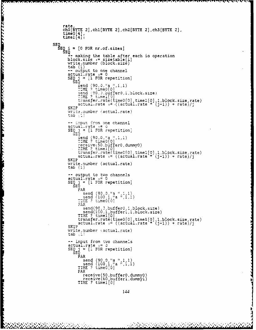
-j W-VV V I .VWWr _ -_.W_%% W- 1.71" U-
rate,chOtBYTE 21,chl(BYTE 2],ch2[BYTE 2],ch3(BYTE 2],timeO r1timel (4
SE~ ?E0 FOR nr.of.sizes]
Q - making the table after each io operationblock.size :=sizetableli]write.number (block.size)tab (1)
-output to one channelactual.rate :=0SEQ j = [1 FOR repetition]
SEQsend (90, a '1
:end (,90, 3,:uf:er0,I,1biock.size).;,ME ? timel[g]ransfer.rate(timeO[Q],timel(O],1,block.size~ rate)
actual-rate :=.((actua±L.rate x (i-i)) + rate)/jSKIPwr.:~uioer (actual.rate)ta z
- - inout --:,m one channelactuaI.rate 3=SEO j =[1 FOR repetition]
SEQsend (90,0,"a :114)TIME ? tm.reO[o1receivek50,bufifer0,dummyO)TIME ? timel[O]
i4j~transfer.z-ate(timeOfa] --me [1,,block.size rate)actual.rate :=((actual rate ' (-1)) + ratej/j
SKIPwz-ite.number (actual.rate)tab (1)
;-output to two channelsactual.rate :=0SE3 j = (1 FOR repetition]
A R
send M0,1,ja ",I''p71":E ? timeO[01
send (90,),buffer0,1,block.size)send(100,1 bufferl,l,block.size)
TIME ? timello]transfer.rate(timeO0] timel[03 ,1,block.size rate)
SKPactual.rate :=((actuai.rate * j-l)) + rate5/jSKIPenme ata~aetab 11
-- input from two channelsactua±.rate :=0SE 3j =[I FOR repetition]
PARsend (90,0,"a 11,1,1)send (MOO,12 " 11
TIME ? time0[OPAR
receive 50,buffer1,dummy12
TIME ? timeltol
144
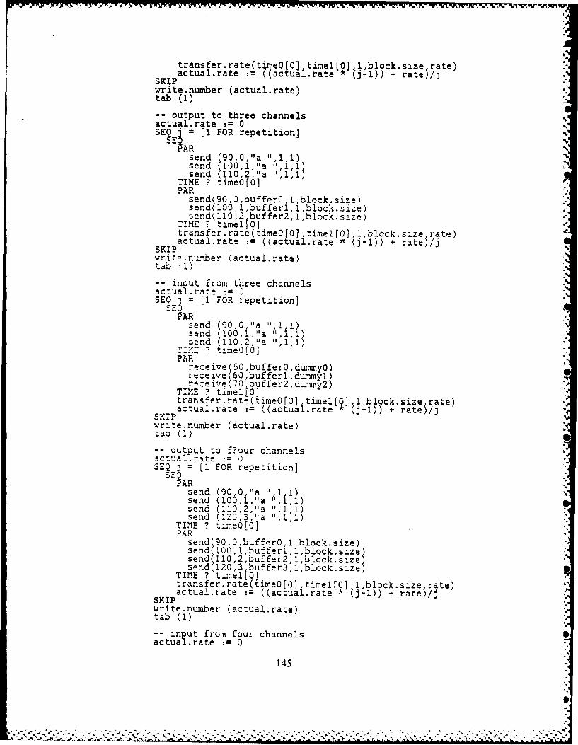
Ir, P6 -i.WM r% %' r"rR
transfer.rate(tineoOO timel[O],1,block.size rate)actual.rate :=((actuai.rate *(j-1i)) + ratej/j
SKIPwrite.nunber (actual.rate)tab (1)
--otput to three channels%actual.rate :=0%SE? Ej =[1 FOR repetition]%
send (90,1,a 11,1,1)send (106,1,"a 11,1,1)send (10,2,1'a 11,1,1)
TIME ? timeO[O]PAR
send (90,0,bufferO,l1.block.size)send ( IO,1,bufferl,:,block.size)send( 110 2 buffer2,i,block.size)
TIME ? time1[o]transfer.rate(timeO[O] timel[O] 1,block.size rate)actual.rate :=((actuai.rate * j-l)) + rateS/j
SKI?write.number (actual.rate)tab ,1)
-- inout from three channelsactual.rate :=0SEQ j = [1 FOR repetition]
5EOPAR
send (90,0,"a "1,11)send (100,1,"a 1",1,1)send (110,22a1,1
=21E ? timeO(O]PAR
receive 50,buffer0,dummyo
receiveM 7 buffer2,dummy2$TIME ? timeito]transfer.rate(timeO[O] timelfol ,1,block.size rate)actual.rate :=((actuai.rate * (-1)) + rate /j
SKIPwrite.number (actual.rate)tab (1)
-- output to f?our channelsactual.rate :=0SEQ 3 = [1 FOR repetition]
PARsend (90,0,11a 11,1 1)send (100,.1,"a "1',1)send (110,2,"a 11,1,1)send 1220 3,"a ,1,1)
TIME ? time6[6]
send (90,0,buffer0,1,block size)send (100,1,buff,'er1,1,block s #e)send (110,2,buffer2 ,1,block.size)spr.d (120,3 buffer3,1,block.size)
TINE ? timeitoltransfer.rate(timeOfo] timel[O] ,1,block.size rate)actual.rate :=((actuai.rate * j-1)) + rateS/j
SKIPwrite.number (actual.rate)tab (1)
-- inp ut from four channelsactual .rate 0
145
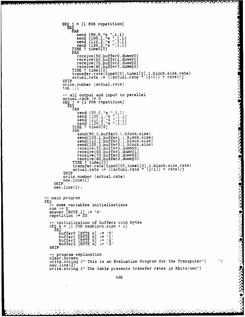
SE KiR[I. FOR repetition]
snd (0,0.."a",)send 100,1,"a",1send (l10'2,"a 11,1,11send (120'3,"a "l
TIME ? time6lloPAR
receive (50 ,buffer , dunmoreceive(60 ,bufferl , duxyl)receive (70 ,buffer2 ,dumrny2)receive (80 buffer3,dummy3)
TIME ? timeltO]transfer.rate(time0(0] timel[0J,l,block.size rate)actual.rate :=((actuai.rate * (j-1)) + ratej/j
SKIP *
write~number (actual.rate)tab )
-all output and input in parallelactual.rate :=0SE? i = [1 FOR repetition]
PARsend (90,0,"a 1",1,1)send (100,1,''a "j1,J,1send (10,2,"a",)send (120,3,1'a 11,1,1)
TIME ? time0(0']PAR
send (90,0,buffer0.,l,block.size)send( 100,l,bufferl,.,block.size)send( l10,2,buffer2,',block.size)send( 120,3,buffer3,1l,block.size)receive 50 ,buffer0 , dumyo)receive;(60 ,bufferl ,duy)receive (70 ,buffer2 , dummy2)receive (80 buffer3,dummy3)
TINE ? timeltO]transfer.rate(timeOIIO] tixel[0Ll ,block.size rate)actual.rate :=((actuai.rate * (-i)) + rate~/j
SKIPwrite.number (actual.rate)
SKPnew.line(1)new .line (1)
-main programSEQ
- - some variables initializationsrun :=0answer [BYTE 1] 'z'repetition 2= 0
-initialization of buffers with bytesS3k= [I FOR maxblock.size + 1]E ufferO [BYTE kI '0'bufferi [BYTE k] Il'1buffer2 BYTE kI '2'buffer3 BYTE k] '3'
SKIP
-- program explanationclear, screenwrite.string ("This is an Evaluation Program for the Transputer")new. line(?)write.string ("The table presents transfer rates in Kbits/sec")
146
x2-
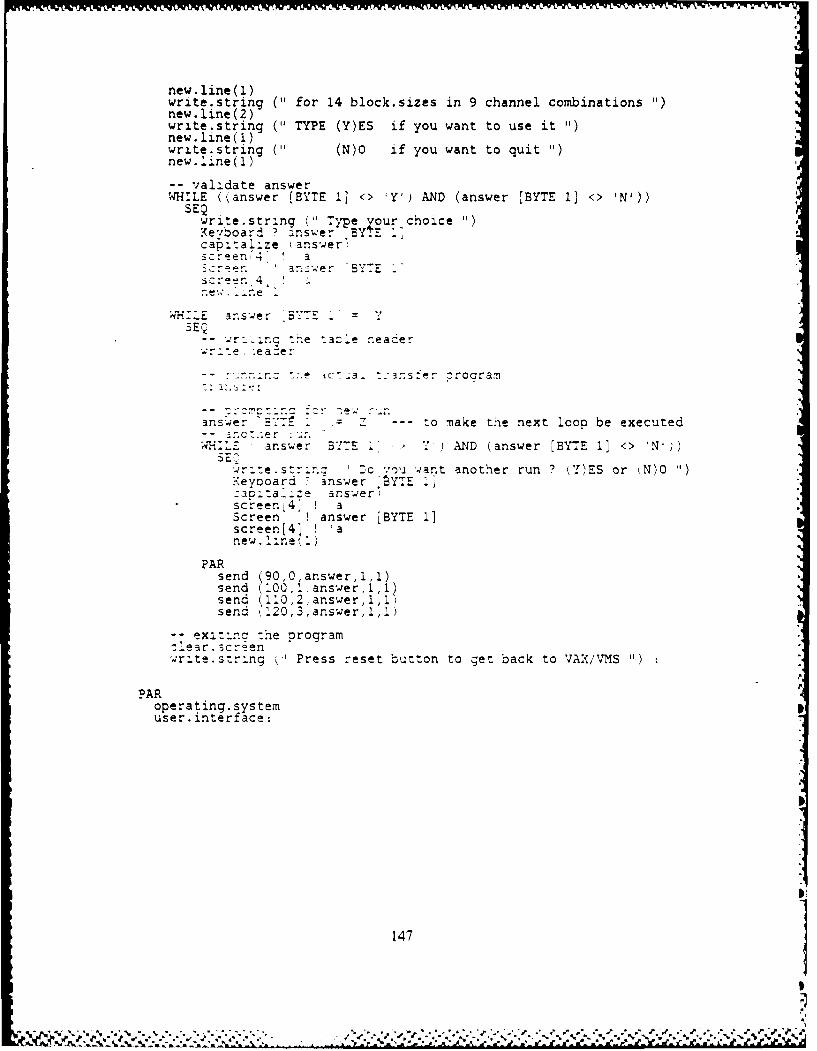
new line( 1)write.string ("1 for 14 block.sizes in 9 channel combinations "1)new.line(2)wri.te.string (11 TYPE (YES if you want to use it "new.line(1)write.string ('1 (N)O if you want to quit "new. line(1)
-validate answerWHILE ((answer [BYTE 13 <> 'Y') AND (answer [BYTE 1] <> IN'))
SEQwrite.string (1 Type our choice '
Kevboard1 I answer BYTE 1:capb.:al:ze answer
r~r. an.~wer E
W1H:..E answer ByTE
-- r.i.rnc --e tazle reacerwr:te ..-.e a e:
-. :,.e 1C 3- -::3sfer Croaramn
answer Z ---Z :o make the next 'ooo be executed
UH23.* answer BY:E 7.' P) AND (answer [BYTE 11 <> 'N';)
write. strir.: :c %mu want another run ? Y)ES or M)O"Keynoard -answer ,SY7E_caoita_.:e answer,Screen 4' '3Screen L ! answer [BYTE 11screen[41 'a'new. l.ine (
PARsend (90,0,answer,1 1)send 200,2.answer,1,2Psend 120,2,answer~,,)send 2.20, 3, answer, 1 ,1)
-zerscreenh rgawrite szring - Press reset button to get back to VAX/VMS U
PARoperating. systemuser. intertace:
147]
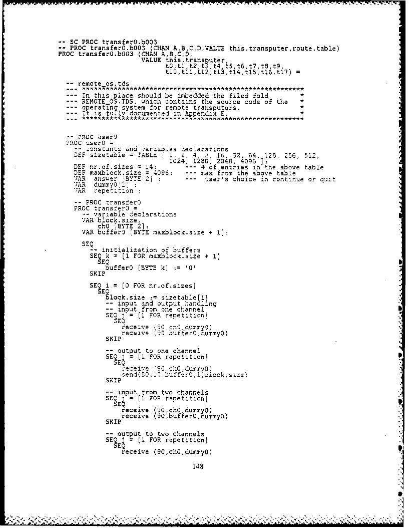
-- SC PROC transferO.b003-- PROC transferO.b003 (CHAN AB,C,D,VALUE this.transputer,route.table)PROC transferO.b003 (CHAN AB C,D,
VALUE thls.transputer,t0,tl,t2,t3.,t4,tS,t6,t7,tS,t9,tlO,tll,tl2,tl3,tl4,tl5,tl6,tl7) =
-remote os.tds
--- In this place should be imbedded the filed fold *REMOTE 0.TDS, which contains the source code of the *Soperating system for remote transputers. *it is fully documented in Appendix E. *
-- ?ROC userO?ROC userO =
-- zonstants and .,ariabies deciarationsDEF sizetable = TABLE 1 1, 2, 4, 3, 16, 32, 64, 128, 256, 512,
1024, 1280, 2048, 4096 3:DEF nr.of.sizes = 14: --- # of entries in the above tableDEF maxblock.size = 4096: --- max from the above tableVAR answer rBYTE 2' - user's choice in continue or cuitVAR dummvOt?7AR repetzion
-- PROC transferOPROC transferO =
-- variable declarationsVAR block.size,
chO [BYTE 2]:VAR buffer0 'BYTE maxblock.size + 1]SEQ
-- initialization of buffersSE3 k = [1 FOR maxblock.size + 1]5EO
SufferO [BYTE k] := '0'SKIP
SE i = [0 FOR nr.of.sizes]
6lock.size : sizetable~i]-- input and output hancling-i nput from one channelSE2 j = [1 FOR repetition]
receive (90,ch ,dummy').rective '90 buff-er0,dummy0)
SKIP
-- output to one channelSEEj = [1 FOR repetition]
receive /90,chOdummyo)send(50,10,buffer0,1,!)iock.size)
SKIP
-- input from two channelsSE3Ej = (I FOR repetition]
receive (90,chOdummy0)receive 90,buffer0,dummyo)
SKIP
-- output to two channelsSEJ= [1 FOR repetition]
receive (90,chO,dummyo)
148
'.% % % . . . - . - -- % -. ,. % - - - * - % % . *. % % . % % . % . . % % . -. %+% % ".-, . ,
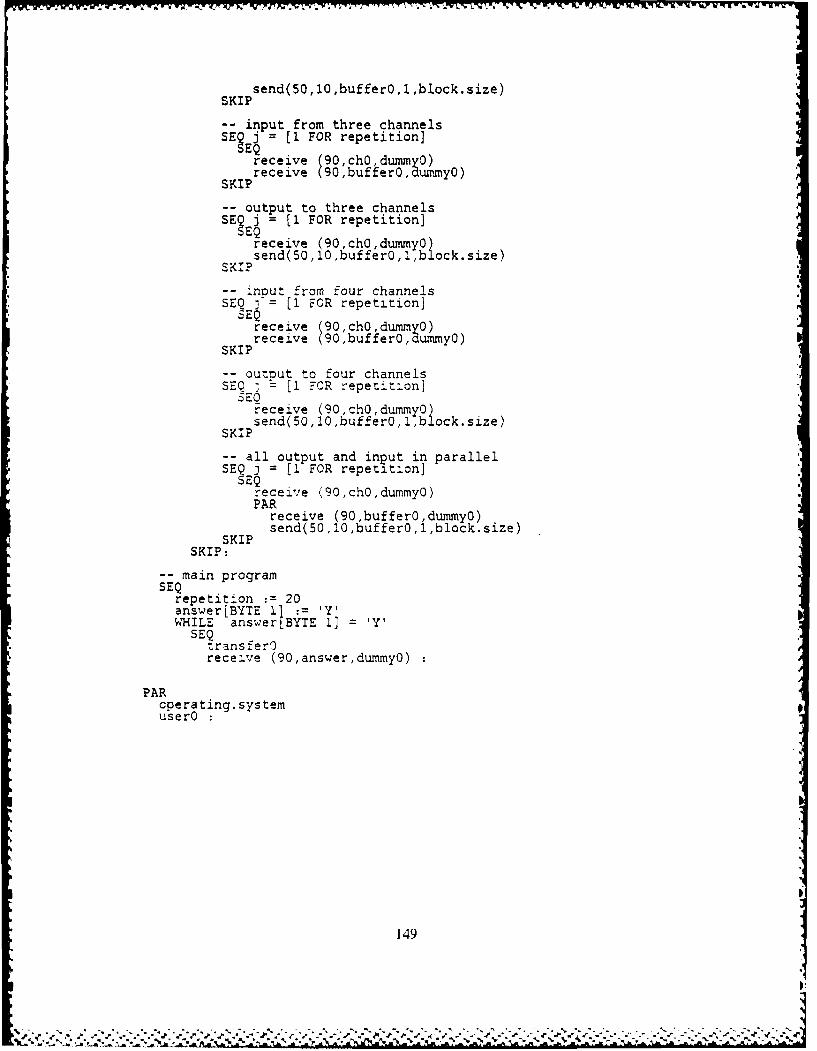
wrwr~wA7 w~"%FCwrX'q wX~xVY
SKPsend(50,10,buffer0,l ,block.size)
-- input from three channelsSEj Q l( FOR repetition]
receive (90,ch0, dunmo)SKPreceive (90, bufferO, durmyO)
--,output to three channelsSE j = [1 FOR repetition]
receive (90,cho, dummy0)send(50,10,buffero,l,block.size)
SKIP
- - inout from four channelsSEQ 3 = 1 FOR repetition]
SEQreceive (90,ch0,duny)
SKPreceive (9,buffer0, aummyO)
-outnut to four channelsSEQ [I -70R repetition]
receive (90,ch0, durnmy ocksie
SKIPed5,0bfer,~lc~ie
-all output and input in parallelSEQ j = [1i FOR repetition]
SEQreceive K 90, chO ,dummyO0)PAR
receive (90,bufferO,dummyO)SKPsend(50,10,buffer0,l,block.size)
SKIP
-main programSEQ
repetition :=20answer [BYTE I1.1lyWHILE answerIBYTE 1]= Y
SEQ-
receive (90,answer,dummy0)
PARoperating. systemuserO
149
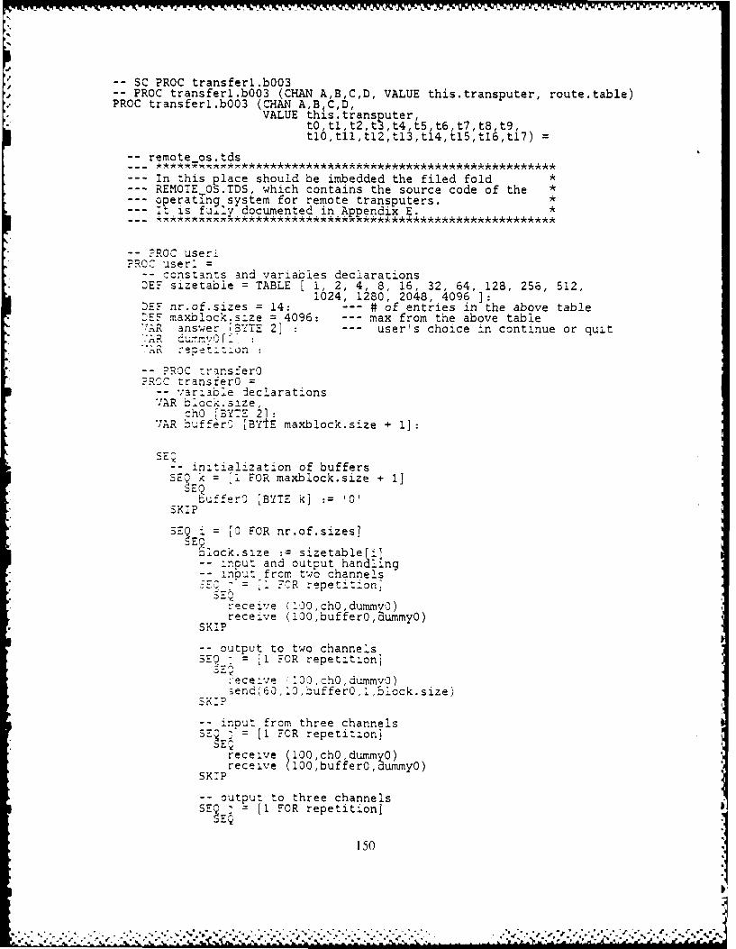
-- SC PROC transferl.b003-- PROC transferl.b003 (CHAN A,B,C,D, VALUE this.transputer, route.table)PROC transferl.b003 (CHAN A,B C,D,
VALUE this.trans puter,tO,tlt2,t3,t4,t5,t6,t7,t8,t9,tlO,tlltl2,tl3,tl4,tl5,tl6,tl7) =
-remote os.tds
--- In this place should be imbedded the filed fold *--- REMOTE OS.TDS, which contains the source code of the *--- operating system for remote transputers. *1, is fuily documented in Appendix E.*
-- ?ROC user!PROC userl =
-- constants and variables declarationsDEF sizetabie = TABLE [ 1, 2, 4, 8, 16, 32, 64, 128, 256, 512,
1024, 1280, 2048, 4096 1:DEF nr.of.sizes = 14: --- # of entries in the above tablenEF maxblock.size = 4096: --- max from the above tableAR answer TBYTE 2] --- user's choice in continue or quit
"'A .- epeti:ion:
-- PROC trans:er0z-ROC transferO =
-- variable declarationsVAR block.size,
Cho [BYTE 2]:7AR bufferO [BYTE maxblock.size + 1]:
-- initialization of buffers5E Ek = [I FOR maxblock.size + 1J
bufferO [BYTE k] := '0'
SKIP
S i= [0 FOR nr.of.sizes]
S lock.size := sizetablefi]-i- nput and output handling
-nbut from two channelsr- 7CR repet toni
receive (100,cho,dummyo)receive (100,buffer0, ummyo)
SKIP
-- output to two channelsSE?: = [I FOR repetition]
:eceve 13o,chO,dummvo)5end(60,o0,buffer0,I,51ock.size)
SKIP
-- input from three channelsSE : = [I FOR repetition]
receive (100,ch0,dummyO)receive (100,bufferO,dummyO)
SKIP
-- output to three channelsSE j = (I FOR repetition]
150
-." ." .'. ..'.. ." . ." . , ..'<. .' v.' '.'-) .'...') ''..- '.''. .': ':- -'.."-. .. ..'"." " • " .. . .- "" " " ""

receive (100ch0,dummy0) "send(60,10,bffe0,1,51ock.size)
SKIP !--input from four channelsS j =u[1 FOR repetition]SEE
receive 100,chO, dumny0)SKIPreceive (100,bux'fer0, ummyo)
-- output to four channelsSE? j = [1 FOR repetition]
receive (i00,chO,dummvy)send(60,i0,bufferO i,5lock.size)
SKIP
-- all output and input in parallelSEQ ] = [1 FOR repetitionj
SEQreceive (100,ch0,dummy0)PAR
receive (100,buffer0,dummvO)send(60,:0,buffer0,Iblock.size)
SKIPSKI?: '
-- main programsEQrepetition := 20answer[BYTE 11 := lY'WHILE answer[BYTE 1] IT
SEQ .ransfer0receive (100,answer,dummy0)
PARoperating.systemuserl
151

-n IN -, ro -. -j . -. -. -v -. a -J d-- Y- -7 F77 - 7 , 7 *1 R -2 M . 77.%-v v.
-SC PROC transfer2.b003-- PROC transfer2.b003 (CHAN A,B,C,D,VALUE this.transputerroute.table)PROC transfer2.b003 (CHAN A,B C,D,
VALUE this.trans uter,tO,t,t2,t3,t4,t5,t6,t7,t8,t9,tl0,tll,tl2,tl3,tl4,tl5,tl6,tl7)=
-remote os.tds
--- In this place should be imbedded the filed fold *REMOTE OS.TDS, which contains the source code of the *operating system for remote transputers. *It is fully documented in AppendixE.
PROC user2N PROC user2=
-- constants and variables declarationsDEF sizetable = TABLE [ 1, 2, 4, 3, 16, 32, 64, 128, 256, 512,
1024, 1280, 2048, 4096 ]:DEF nr.of.sizes = 14: --- # of entries in the above tableDEF maxblock.size = 4096: --- max from the above tableVAR answer [BYTE 2] : --- user's choice in continue or auitVAR dummyO[1]V;AR repecition
-- PROC transferOPROC transferO =-- variable declarationsVAR block.size,
ch0 [BYTE 2]:VAR bufferO [BYTE maxblock.size + 11:
SEQ-- initialization of buffersSEQ k = [1 FOR maxblock.size + 1]
bufferO [BYTE k] := '0'SKIP
SE3 i = [0 FOR nr.of.sizes]
block.size := sizetable[i]-- input and output handling-- inbut from three channelsSEQ j"= [1 FOR repetizionj
SEQreceive (110,chOdummy0)receive (110,buffer0,aummyo)
SKIP
-- output to three channelsSEQ j = [1 FOR repetition]
SEQreceive (110,ch0,dummv0)send(70,40,buffer0,1,Block.size)SKIP
-- input from four channelsSE j = [1 FOR repetition]
receive (l1O,chOdummyO)receive l0,bufferO, ummyO)
SKIP
-- output to four channelsSErEj [1 FOR repetition]
152
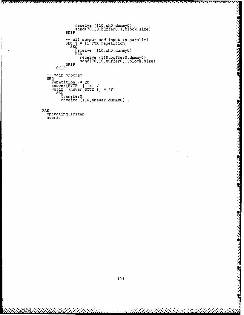
receive (11O,chO,dumygO)send(70,1O,buffer O,l,bloc k.size)
SKIP
-all output and input in parallelSE j = [1 FOR repetition]
receive (11O,ch0,dummy0)PAR
receive (110,bufferO ,dummyasend(70,1O,bufferO.1,blocK .size)
SKIPSKIP:
-main programSEQ
repetition :=20answer(BYTE 11 := YWHILE answerLBYTE 1] = Y
SEQtrans fe rOreceive (110,answer,dummyO)
PARoperating. systemuser2:
153
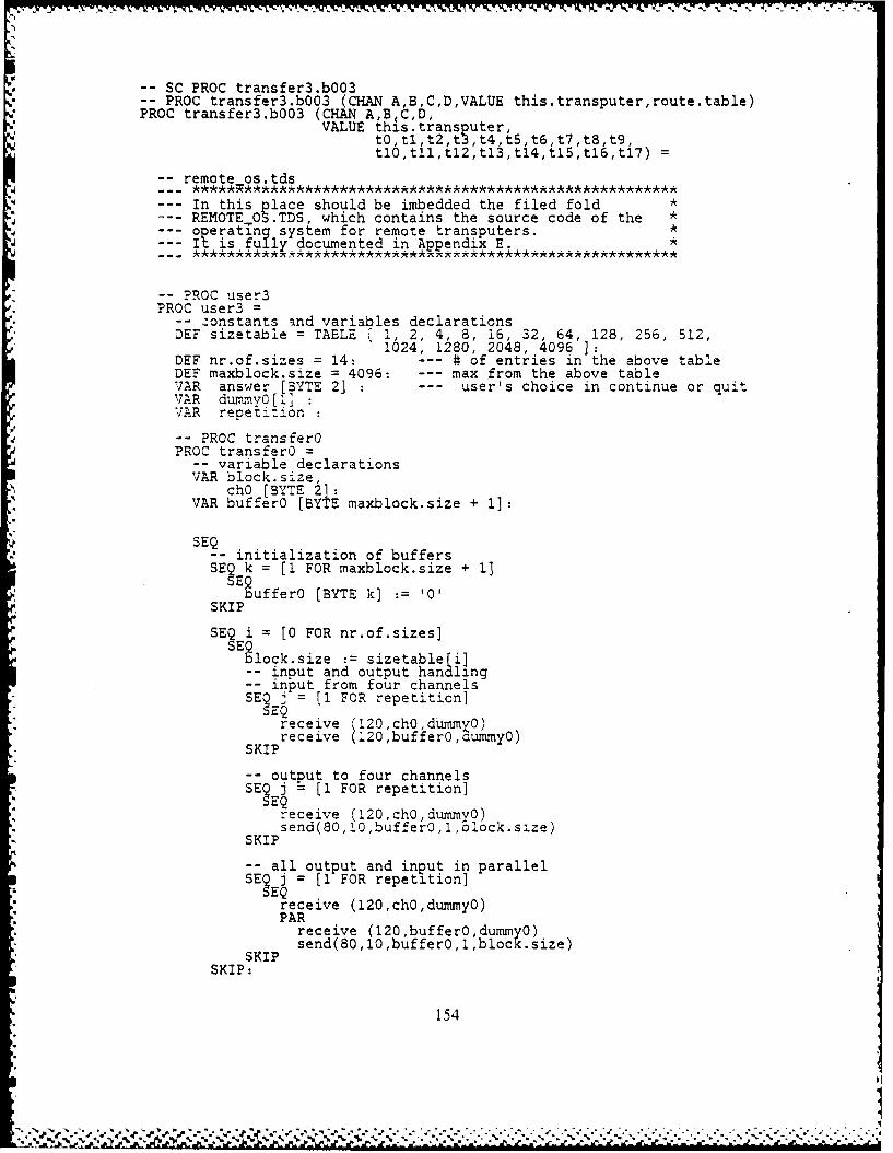
SC PROC transfer3.b003-- PROC transfer3.b003 (CHAN A,B,C,D,VALUE this.transputer,route.table)PROC transfer3.b003 (CHAN A,B C,D,
VALUE th3s.transputer,tO,tl,t2,t3,t4,tSt6,t7,t8,t9tl0,tll,tl2,tl3,tl4,tl5,tl6,ti7)=
-remote os.tds
In this place should be imbedded the filed fold *REMOTE OS.TDS, which contains the source code of the *operating system for remote transputers. *It is fully documented in Appendix E. *
-*PROC user3PROC user3 =
-- :onstants and variables declarationsDEF sizetable = TABLE [ 1, 2, 4, 8, 16, 32, 64, 128, 256, 512,
1024, 1280, 2048, 4096 ]:DEF nr.of.sizes = 14: --- # of entries in the above tableDEF maxblock.size = 4096: --- max from the above tableVAR answer [BYTE 2] --- user's choice in continue or quitVAR dummy0[! :VAR repet::.on
-- PROC transferOPROC transferO =
-- variable declarationsVAR block.size,
chO [BYTE 2]:VAR buffer0 [BYTE maxblock.size + 1]:
SEQ-- initialization of buffersSEE k = [1 FOR maxblock.size + 11
SPufferO [BYTE k] := '0'SKIP
SEQ i = [0 FOR nr.of.sizes]SElock.size := sizetable i]
-- input and output handling-- input from four channelsSEQ j = [1 FOR repetition]
SEQreceive (120,chO,dummyO)receive (120,buffero,aummy0)
SKIP
output to four channelsSEEj = [1 FOR repetition]
receive (120,ch0,dummy0)send(80,10,buffer0,1,zlock.size)
SKIP
-- all output and input in parallelSE Z~j = [1 FOR repetition]
receive (120,ch0,dummyO)PAR
receive (120,buffer0,dummyO)send(80,10,buffero,l,block.size)
SKIPSKIP:
154
del-
* £ i P- -*. t-- . - -Y -w V . V7 . T.
-main programSEQ
repetition :=20answer[BYTE 11 : y
* WHILE answer IBYTE 1] =1YSEQ
trans fe rOreceive (120,answer,dummyo)
PAR* operating.system
user3
* 155

-- confiqu ration-Link Definitions
DEF link~out = 0:DEF linklout = 1:DEF link2out = 2:DEF link3out =3:DEF link~in=4:
DEF link2in=6:DEF link3in =7:
DEF root = 10:DEF rnax~pipes =20:CHAN pipe [max.pipesl:
PLACED PAR-- PROCESSOR rootPROCESSOR root
PLACE pipe (0] AT link~inPL.ACE pipe 2 AT linklinPLACE pipe (4] AT link2inPLACE oiDef } AT link3inPLACE biloe f' AT link~Out?LACE bibe,131 AT 11inioutPLACE bibel5i IT link2out?LACE pi~eM7 AT iink3out
hostproc (pipefO] ,pipeF2] ,pioer41 ,pipe[6J.
4,5,6,7,0,0,0,0,0,0,0,0,0,0,0,0,0,0)
- - PROCESSOR 0PROCESSOR 0
PLACE pipe [11 AT link~in :PLACE pipe 9] AT linklin :PLACE pipe 0] AT link~out:PLACE pipe 8 AT linklout:
transferO.b003 ( ipe(1] ,pipe(9] ,pipe(0j ,pipe[8],
0,6,,5,7,0,0,0,0,0,0,4,0,0,0,0,0,O,0)
-- PROCESSOR 1PROCESSOR I
PLACE pipe(3l AT li4nk~inPLACE pipeLIO] AT linklinPLACE pipe12] AT 2ink~outPLACE pipe[1 1] AT linklout
transferl.b003 ( ipe(3j,pipe[10] ,pipe[2],pipe[11],
7,0,6,5,0,0,0,0,0,0,4,0,0,0,0,0,0,0)
-- PROCESSOR2PROCESSOR 2'PLACE oice,5' AT link~inPLACE kip '81 AT linklinPLACE pipe 41 AT link~out:PLACE pipe(9] AT linklout:
transfer2.b003 (pipe[S] ,pipe[8] ,pipell4] ,pipe[91,
5,7,0,6,0,0,0,0,0,0,4,0,0,0,0,0,0,0)
156
%i

-- IK7 PROCESSOR K3 I W K'x-ov
PROCESSOR 3PROCESSOR 3
PLACE pipe 71 AT ink0in :PLACE pipe 1 ) AT linklin :PLACE pipe 6] AT link~out:PLACE pipe 101 AT linklout :
transfer3.b003 (3ipe[7],pipe Ii] ,pipe[6] ,pipe[10],
6,5,7,0,0 0,0,0,0,0,4,0,0,0,0,0,0,0)
157
" %.., , ." '. -;.'.. " .'-.,""- " '. - .' .''. .','._,L' ,:.' " "" ,."",''. '':"-.-' -'- ", " "" " "" . , " "". ""'"""-21
!. :A -J . ,w.:. -"A~ 'w'i ry. d ; . , ) ' " )' - '
. ,1.. .. .. , , '~ .'7 , ~ ~ ) V~y x . ._
Im
LIST OF REFERENCES
1. Garret, D. R., A Software System Implementation Guide and System PrototypingFacility for the MCORTEX Executive on the Real Time Cluster, M.S. Thesis,Naval Postgraduate School, Monterey, California, December 1986.
2. Rowe, W. R., .Idaptio,,z ,f WCORTEX to the AEGIS Simulation Environment,M.S. Thesis. Naval Postgraduate School. Monterey, California. June 1984.
3. INMOS Limited, The Transputer Family, June 1986.
4. I'N MOS Limited, I.S BO01 Evaluation Board UserManual. 1985.
5. INMOS Limited, I.VS 2003 Evaluation Board User Manual, 1985.
6. INMOS Limited, IMS B004 Evaluation Board User Manual, 1985.
7. Evin, B. , Implementation of a Serial Delay Insertion Type Loop Communicationfor a Real Time Multitransputer System. M.S. Thesis, Naval Postgraduate School,Monterey, California, June 1985.
8. Selcuk, Z., Implementation of a Serial Communication Process for a FaultTolerant, Real Time, Multitransputer Operating System, M.S. Thesis, NavalPostgraduate School, Monterey, California, 1984.
9. Vanni, J. F., Test and Evaluation of the Transputer in a Muititransputer SystemConfiguration, M.S. Thesis., Naval Postgraduate School, Monterey, California,June 1987.
10. INMOS Limited, IMS D600 Transputer Development Syitem, 1985.
11. Shepherd Roger, Extraordinary use of transputer links, INMOS Technical note I.November 1986.
158
7I

- -- ,. 'A
BIBLIOGRAPHY
Heath M. T,, The Hyvercube: A Tutorial Overview, Oak Ridge 'National Laboratory,19S6.Z
INMOS Corporation, Compiler Writers Guide, Draft, 1986.%
INMO10S Limited. OCC.-M Programming Manual, 1983.
INNIOS Liie.Transpuitor Refrtrnce M anual. October 1986.
P-eterson & Silherschatz. 'Oceratnnq Svstems Concepts. Addison-Weslev Publishing C3..Inc.. i983.
Tanenbaum A. S., Computer ,Vetworks, Prentice Hall, New Jersey, 1981.
Weitzmnan C.. Dis.,ributed Mficro' Minicomputer Systems, Prentice---all, New JeIrsey,
159
_Ile

INITIAL DISTRIBUTION LIST
No. CopiesI. Defense Technical Information Center 2
Cameron StationAlexandria, VA 22304-61,15
2. Library. Code 0142 2Naval Postgraduate SchoolMonterey. CA 93943-5002
3. Department Chairman. Code 52Department of Computer ScienceNaval Postgraduate SchoolMonterey, CA 3943
4. Dr. Uno R. Kodres. Code 52KrDepartment of Computer ScienceNaval Postgraduate SchoolMonterey, CA 93942
5. Dr. Daniel L. Davis, Code 52DvDepartment of Computer ScienceNaval Postgraduate SchoolMonterey, CA 93943
6. Daniel Green. Cnode 20FNaval Surface Weapons CenterDahlgren, VA 22449
7. Jerry Gaston, Code N24Naval Surface Weapons Center SDahlgren. VA 22449
S. CAPT. J. Hood. USNoPMS 400B5Naval Sea Systems CommandWashington D.C. 20362
9. RCA AEGIS RepositorvRCA CorporationGovernment Svstems DivisionMail Stop 127-327Moorestown, NJ 08057
10. Library (Code E33-05)Naval Surface Weapons CenterDahlgren, VA 22449
160
• i!IS
11. Dr. M. J. GraliaApplied Physics LaboratoryJohn Hopkins RoadLaurel, MD 20702
12. Dana Small, Code 8242Naval Ocean Systems CenterSan Diego, CA 92152
13. Estado Maior da ArmadaBrazilian Naval Commission4706 Wisconsin Ave., NW.Washington, DC 20016
14. Diretona de Ensino da .\larinhaBrazilian Naval Commission4706 Wisconsin Ave., N.W.Washington. DC 20016
15. Diretoria de Armamento o Comunica 6es da Marinha3razilian Naval Commission4706 Wisconsin Ave., N.W.Washington. DC 20016
16. Instituto de Pesquisas da MarinhaBrazilian Naval Commission"706 Wisconsin Ave.. N.W.Washington, DC 20016
17. Instituto Mititar de EngenhariaPraia Vermelha. UrcaRio de Janeiro, RJCEP 20000, BRAZIL
18. Instituto Tecnoldgico da Aeronautica$5o Jose dos Campos. SPCEP 11000 B,RAZIL
19. Pontificia Universidade CatdlicaR. Marques de Sdo Vicente 225, GaveaRio de Janeiro, RJCEP 20000 , BRAZIL
20. Peze WilsonIN.MOS CORPORATIONP.O. Box 16000Colorado Springs, CO 80935-16000
21. David MayINMOS LTD.1000 AztecWest Almondsbury, Bristol, BS12 4SQ, UK
161
S.
.I

22. MAJ/USAF R. A. Adams, Code 52AdDepartment of Computer ScienceNaval Postgraduate SchoolMonterey, CA 93943
23. LT. Mauricio M. Cordeiro, Br. Navy2Brazilian 'Naval Commission ( DACM)4706 Wisconsin Ave., N.W.Washington. DC 20016
* 24. LCDR. Gilberto F Mota, Br. NavyBrazilian Navai Commission ( DACM)-4706 Wisconsin Ave., N.W.Washington. DC 20016
* 25. LCDR. J. Vanni Filho, Br. Navy1Brazilian Naval Commission (DACM)4706 Wisconsin Ave., N.W.Washington. DC 20016
162
J"r

%9," .~
~-
", .
0
"-.0
% . % •~
' ., '
aT -'." a .
ma9'ma-aa
, ., , . .p '. . ".'I .. - . " #.., ,. "% '," -• ' , " " .. .'_ _ _ _ _ _ _ _ _ _ ' -. "I. - 0" . . " " - - . 'o,", ,"., , . . ,, ., "., ." S s-#'.. . -,'._.- - . - -..- y ," - .. ". " .'..- "...-- ..-- ," . . -- . , " . .. . , '.
* % -. .... , -..- :, 9: :.9., -.. ,,' , ,*. .a-... a--.a-. - .. , -°..-. . .*.. .a. - ..a: . ,'