1419 batnec v2.2 · s-file: 1419 batnec v2.2.docx page 2 of 29 printed: 2017 03 19 21:33 table of...
TRANSCRIPT

BATNEC REPORT PREPARED FOR THE
DEVELOPMENT PERMIT APPLICATION
CMC ENGINEERING AND MANAGEMENT LIMITED
2017 March CMC File: 1419-204

BATNEC REPORT FOR DEVELOPMENT PERMIT CMC Ref. 1419-204
S-file: 1419 BATNEC V2.2.docx Page 2 of 29 Printed: 2017 03 19 21:33
TABLE OF CONTENTS
REVISION CONTROL GLOSSARY 0- EXECUTIVE SUMMARY 1- GENERAL PHILOSOPHY FOR MATERIAL HANDLING 2- MATERIAL HANDLING EQUIPMENT
3- DUST CONTROL 4- RECEIVING
4.1- RAIL UNLOADING PIT 4.2- RAILCAR HANDLING PROCESS
5- STORAGE 6- SHIPPING
6.0- GENERAL 6.1- VESSEL LOADING 6.2- TRUCK LOADING 6.3- RAILCAR LOADING 6.4- CONTAINER LOADING
7- OVERALL PLANT LAYOUT AND ORIENTATION 8- VISUAL IMPACTS
8.1- OVERALL APPEARANCE 8.2- LIGHTING
_____________________________
BATNEC REPORT FOR DEVELOPMENT PERMIT CMC Ref. 1419-204
S-file: 1419 BATNEC V2.2.docx Page 3 of 29 Printed: 2017 03 19 21:33
REVISION CONTROL
DATE CHANGES REMARKSV 1.0 2016/02/26 First pass at first report. mvnV 1.1 2016/03/02 Computer restartV 1.2 2016/03/02 Word restart due to problems with other document.V 1.3 2016/03/11 ContinueV 1.4 2016/03/17 Rev up; many changes and entries. Copy to SRN for visual improvements.V 1.5 2016/03/17 Continue copy to NASV 1.6 2016/03/17 Continue at home.V 1.7 2016/03/21 Revisions in shiploading section.
Up to section on lighting. Copy to SRN for graphic work.V 1.8 mvn 2016/03/22 Continue in lighting sectionV 1.9 mvn 2016/03/23 Introduction Complete; on to graphics cleanup.V 1.10 2016/03/23 Edits by mvn File change to 1419-204
Not actually reved up.V 1.11 2016/03/24 Graphics edits by SRN saved under 1.9 SRNV 1.12 2016/03/29 Final edits by SRN before release.V 1.13 2016/03/29 Review by MVN for release. Issued for use by HemmeraV 1.14 2016/03/30 Comments by LBS Mods by MVNV 2.0 2016/10/27 Replaced P&H with FGT (logo, etc.) & add FGT to Glossary. Redate
cover (March to Oct).PB
V 2.1 2016/11/21 Replaced cover pic. PBV 2.2 2017 03 19 Added Executive Summary
Issued for PERmvn
REVISION

BATNEC REPORT FOR DEVELOPMENT PERMIT CMC Ref. 1419-204
S-file: 1419 BATNEC V2.2.docx Page 4 of 29 Printed: 2017 03 19 21:33
GLOSSARY The following abbreviations, acronyms and consecrated terms are used in this document:
ITEM MEANING Bekaert Bekaert Canada Limited
BATNEC Best Available Technology Not Entailing Excessive Cost CMC CMC Engineering and Management Ltd. EIA Environmental Impact Analysis FGT Fraser Grain Terminal FSD Fraser-Surrey Docks LP – Pacific Rim Stevedoring P&H Parrish & Heimbecker, Limited PMV Port Metro Vancouver
t tonne (1 000 kg)
_____________________________

BATNEC REPORT FOR DEVELOPMENT PERMIT CMC Ref. 1419-204
S-file: 1419 BATNEC V2.2.docx Page 5 of 29 Printed: 2017 03 19 21:33
0- EXECUTIVE SUMMARY
The international grain industry is not in its infancy and Canadian products and installations enjoy a worldwide reputation for consistently high quality. FGT’s goal has been to create a facility that maintains this high level reputation. Therefore, in the development of the preliminary design of Fraser Grain Terminal, care has been taken to consistently chose the techniques that are, in the Owner and the Engineer’s opinions, the best solutions available for minimising environmental impact. In some cases, design changes were made in order to accommodate “better” solutions even though they involved higher capital and operating costs.
In its description of “Best Available Techniques”, Article 3(10) of the Industrial Emissions Directive 1 defines: “best” means most effective in achieving a high general level of protection of the
environment as a whole. “available” means those developed on a scale which allows implementation in the
relevant industrial sector, under economically and technically viable conditions…
The objective of this document is to present a summary of the different techniques that were chosen and to describe why they were selected as the “best”. At the onset of the design process, FGT made it clear that they wished to construct a terminal that would utilise the best of the currently available technologies from the points of view of safety, environmental effects, energy utilisation, product quality maintenance and overall efficiency. The remainder of this report delves into the details of the results of these design decisions on an area and function basis.
_____________________________
1 Directive 2010/75/EU (PDF; 2.78 MB) of the European Parliament and of the Council of 24 November 2010 on industrial emissions (integrated pollution prevention and control).

BATNEC REPORT FOR DEVELOPMENT PERMIT CMC Ref. 1419-204
S-file: 1419 BATNEC V2.2.docx Page 6 of 29 Printed: 2017 03 19 21:33
1- GENERAL PHILOSOPHY FOR MATERIAL HANDLING Grain handling facilities have been in existence for millennia and the use of enclosed silos, bucket elevators and conveyors capable of handling bulk product first originated approximately 175 years ago. Operation of these latter facilities has always been subject to the risks inherent in the handling of bulk grain products, namely the production of grain dust, its subsequent release into the surrounding air volumes and, subsequently, the creation of potentially explosive air-dust mixtures. As the throughput rates of grain handling facilities increased during the 20th century, the industry witnessed an increase in the frequency and intensity of accidents due to grain dust explosions. The latter half of the century saw a concerted effort to study the phenomenon involved and to find mitigating measures. Today, standards exist worldwide regarding the precautions and restrictions to be taken in the design, operation, and maintenance of grain handling facilities. In the USA for instance, recommendations on this matter introduced in 1988 by OSHA have produced “stunning”2 results in reducing the frequency of explosions in grain handling facilities in the USA. Most of the techniques involved in dust explosion reduction involve the following: Containment of dust produced. Collection of dust produced. Minimisation of the effects of an explosion. These techniques are now commonplace in new grain handling installations and will, of course, be part of the Fraser Grain Terminal design. However, Fraser Grain Terminal will be going beyond these standard requirements and will feature design elements introduced to minimise the amount of dust produced in the first place.
2 “Frequency of Dust Explosions in Grain Storage”; DEMONTIS; Giorgio; CREMANTE; Mio; Tecnica Molitoria International, vol 63 – n.13/A, 2012, page 70.
BATNEC REPORT FOR DEVELOPMENT PERMIT CMC Ref. 1419-204
S-file: 1419 BATNEC V2.2.docx Page 7 of 29 Printed: 2017 03 19 21:33
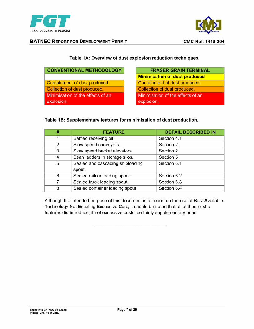
Table 1A: Overview of dust explosion reduction techniques.
CONVENTIONAL METHODOLOGY FRASER GRAIN TERMINAL Minimisation of dust produced Containment of dust produced. Containment of dust produced. Collection of dust produced. Collection of dust produced. Minimisation of the effects of an explosion.
Minimisation of the effects of an explosion.
Table 1B: Supplementary features for minimisation of dust production.
# FEATURE DETAIL DESCRIBED IN 1 Baffled receiving pit. Section 4.1 2 Slow speed conveyors. Section 2 3 Slow speed bucket elevators. Section 2 4 Bean ladders in storage silos. Section 5 5 Sealed and cascading shiploading
spout. Section 6.1
6 Sealed railcar loading spout. Section 6.2 7 Sealed truck loading spout. Section 6.3 8 Sealed container loading spout Section 6.4
Although the intended purpose of this document is to report on the use of Best Available Technology Not Entailing Excessive Cost, it should be noted that all of these extra features did introduce, if not excessive costs, certainly supplementary ones.
_____________________________

BATNEC REPORT FOR DEVELOPMENT PERMIT CMC Ref. 1419-204
S-file: 1419 BATNEC V2.2.docx Page 8 of 29 Printed: 2017 03 19 21:33
2- MATERIAL HANDLING EQUIPMENT An important factor in the operation of a grain shipment facility is the need to preserve the quality of the product being handled. The material handling equipment, in particular the conveyors and bucket elevators, play a major part in this quality control. In general, the faster the speed at which the product is being moved, the higher will be the breakage and the amount of dust created due to the turbulence and the air displaced by the product. Therefore, the following parameters were set for the material handling equipment:
Table 2A – Design Characteristics for Material Handling Equipment
# ITEM KEY PARAMETER REMARKS 1 BELT CONVEYORS 2 Maximum speed 500 feet/min (2.5 m/s) To reduce breakage and
dust. Conventional designs uses speeds of approximately 650 feet/min (3.25 m/s).
3 Maximum incline 10 degrees To prevent roll-back of material.
4 Construction type Totally enclosed For elimination of dust emissions. Allows material to be transported during periods of rain.
5 Material of construction
Galvanised steel Less maintenance than with mild, painted steel. Most suitable for marine environment.
6 Self-cleaning features Motorised cleaner brush. Head end scraper (carrying side). Tail end scraper/plough (return side).
To minimise cross-contamination of products.

BATNEC REPORT FOR DEVELOPMENT PERMIT CMC Ref. 1419-204
S-file: 1419 BATNEC V2.2.docx Page 9 of 29 Printed: 2017 03 19 21:33
# ITEM KEY PARAMETER REMARKS 7 Dust control Self-contained reloading
dust filter for each conveyor.
Create negative pressure inside conveyor plenum in order to minimise fugitive dust emissions.
8 BUCKET ELEVATORS 9 Maximum speed 500 feet/min (2.5 m/s) To reduce breakage and
dust. Conventional designs uses speeds of approximately 650 feet/min (3.25 m/s).
10 Discharge type Semi-centrifugal To reduce breakage and dust.
11 Boot type Gravity take up Floating type Self-cleaning system
To minimise cross-contamination of products.
12 Material of construction
Galvanised steel Less maintenance than with mild, painted steel. Most suitable for marine environment.
13 Dust control Self-contained reloading dust filter for each conveyor.
Create negative pressure inside conveyor plenum in order to minimise fugitive dust emissions.
_____________________________

BATNEC REPORT FOR DEVELOPMENT PERMIT CMC Ref. 1419-204
S-file: 1419 BATNEC V2.2.docx Page 10 of 29 Printed: 2017 03 19 21:33
3- DUST CONTROL Traditional dust control philosophy has centered on the principle of capturing airborne dust, transporting it to centralised dust filters and then consolidating the collected dust in powder form for treatment (usually pelletizing) or disposal. At Fraser Grain Terminal, dust emissions will be controlled differently using a two part approach: Emphasis will be placed upon reducing the amount of airborne dust that is created. What little airborne dust is created will be collected as close as possible to its source
and then returned to the product stream. As a result, Fraser Grain Terminal will not utilise the large, centralised, bag-houses that are prevalent in the other grain terminals around the PMV area. These bag-houses have traditionally been the largest user of electrical power in the terminals and also the highest source of noise pollution and explosions. Aspiration points will be required at various locations in the plant where positive pressure will occur either: due to turbulence from transfer points or, due to the filling of enclosed bins or hoppers. These positive pressure areas will be relieved with the installation of cartridge type air filters. The dust collected on the filter cartridges will be regularly dropped back on to the product stream, but in a compacted, caked form to avoid being re-aspirated.

BATNEC REPORT FOR DEVELOPMENT PERMIT CMC Ref. 1419-204
S-file: 1419 BATNEC V2.2.docx Page 11 of 29 Printed: 2017 03 19 21:33
Figure 3A – Example of cartridge type air filters
__________________________
#1- Typical stand-alone dust filter (mounted on top of a surge bin)

BATNEC REPORT FOR DEVELOPMENT PERMIT CMC Ref. 1419-204
S-file: 1419 BATNEC V2.2.docx Page 12 of 29 Printed: 2017 03 19 21:33
4- RECEIVING 4.1- RAIL UNLOADING PIT In Canada, all grain railcars are completely enclosed to shield the product from the elements during transport and are of the bottom dump style for maximum unloading speed. Depending upon the vintage and precise model, the typical railcar holds approximately 90 tonnes of grain (wheat equivalent). Equipped with either three of four horizontal discharge gates, an individual car can be completely drained in a manner of minutes. Although desirable from a throughput perspective, this rapid discharge process into a previously empty receiving hopper generates large amounts of dust and air movement. Left unchecked, the air blowing out of the unused portions of the receiving hopper can release dense dust clouds in the unloading building which create dust explosion hazards, unhealthy air quality, and can block visibility to the point where operations must cease until the dust has settled and been cleaned up. Fraser Grain Terminal’s unloading pit will be equipped with two features specifically designed to eliminate these dust blow outs and their inherent problems: The top of the receiving hoppers will be equipped with a set of gravity actuated
dampers developed by CMC Engineering. These dampers are normally closed and open only when grain is poured on to them thus: o allowing product free passage into the receiving hopper, and o creating a seal to prevent the displaced air from escaping the hopper through the
unused portions of the receiving grating. The hopper itself will be equipped with a dust aspiration system that will draw out the
displaced air (along with the dust in suspension) thus minimising the creation of a positive pressure situation in the hopper. The captured dust will be collected outside of the receiving building and will be returned (in caked form) to the main flow path downstream of the receiving hopper.

BATNEC REPORT FOR DEVELOPMENT PERMIT CMC Ref. 1419-204
S-file: 1419 BATNEC V2.2.docx Page 13 of 29 Printed: 2017 03 19 21:33
Figure 4.1A – Examples of counterweighted baffle
4.2- RAILCAR HANDLING PROCESS In terms of deleterious side effects from handling railcars, the principle issues are: Noise from the railcars due “knuckle slap” generated every time the cars are put into
motion or brought to a standstill. Noise and air pollution from the locomotive (particularly at each acceleration).
In order to minimise these effects the following features will be implemented at Fraser Grain Terminal: The ultimate mode of operation of the facility will utilise true continuous unloading
action of the incoming trains. This methodology will generate the least amount of noise and exhaust emissions for the following reasons:
#1- Top view of counterweighted baffle in closed position.
#2- Cross-section of counterweighted baffle.

BATNEC REPORT FOR DEVELOPMENT PERMIT CMC Ref. 1419-204
S-file: 1419 BATNEC V2.2.docx Page 14 of 29 Printed: 2017 03 19 21:33
Table 4.2A – Railcar Handling Techniques
# ACTIVITY BATCH PROCESSING OF CARS
CONTINUOUS UNLOADING
1 Break up incoming unit train into segments sufficiently short for the PARY facility.
YES Not required
2 Handling of full railcars for unloading.
In batches of 19 cars at a time.
One continuous string of cars.
3 Handling of empty railcars after passage through unloading building.
In batches of 19 cars at a time.
One continuous string of cars.
4 Recombination of empty car strings into a complete train ready for departure.
YES Not required
5 Time required to unload a 100 car train.
6.45 hours 5.0 hours.
6 Number of locomotive moves.
≈37 Each movement
requiring acceleration from dead stop.
One Continuous
movement at ≈ idle speed.
7 Number of “knuckle
slaps”.
≈13 Some with full cars,
some with empty cars.
Theoretically nil. Only if train is
required to come to a stop during the unloading operation.
This continuous unloading process will not be possible until PMV constructs the two planned overpasses into the Fraser Grain Terminal site. Until this time, the unloading
BATNEC REPORT FOR DEVELOPMENT PERMIT CMC Ref. 1419-204
S-file: 1419 BATNEC V2.2.docx Page 15 of 29 Printed: 2017 03 19 21:33
operation will utilise the batch processing of the railcars. This latter processing method has been optimised for noise, air emissions, and speed by the following features: The extension of track 94 in PARY. The addition of two supplementary turnouts in PARY. The relocation or re-alignment of two turnouts in PARY. These features have been included specifically to minimise the locomotive moves and the car connections (that generate knuckle slap). Furthermore, the unloading pit will be placed at a high point of the terminal’s rail loop in order to provide tension on the couplers and thus minimise the noise generated through knuckle slap as the cars are indexed one at time over the unloading pit.
_____________________________

BATNEC REPORT FOR DEVELOPMENT PERMIT CMC Ref. 1419-204
S-file: 1419 BATNEC V2.2.docx Page 16 of 29 Printed: 2017 03 19 21:33
5- STORAGE
The silos that will be used at Fraser Grain Terminal will be fabricated of steel with overlapping, corrugated sheets bolted together to provide an efficient dust and water tight containment. The silos will be fabricated from galvanized steel to provide better visual impact and to eliminate the need to repaint on a regular basis. Grain storage silos can often contain high amounts of suspended dust due to the large drop heights involved (particularly when the silos are empty or close thereto). In order to eliminate this problem, the silos will be equipped with several mitigating features: Flow retarders (AKA “bean ladders”) developed by CMC Engineering, mounted in the
centres of all of the silos. As the name suggests, these devices slow the material flow down by providing a cascading arrangement as opposed to a full free-fall path. This procedure produces two benefits: o The effective drop height is reduced from as much as 28.0 m down to
approximately 2.8 m. o The material flow is kept intact thus eliminating the entrainment of air that would
otherwise occur. As a result, the amount of dust thrown into suspension is greatly reduced. The silos will be continuously aspirated during the filling process thus removing what
little remaining suspended dust is released from the bean ladders. In a bit of a “belts and suspenders” approach, the silos will also be equipped with explosion relief venting should there be a malfunction in the mitigating features here above. The silo roofs will be designed to peel open and vent any undesirable pressure that might otherwise blow open the silo walls.

BATNEC REPORT FOR DEVELOPMENT PERMIT CMC Ref. 1419-204
S-file: 1419 BATNEC V2.2.docx Page 17 of 29 Printed: 2017 03 19 21:33
Figure 5A – Examples of the effectiveness of a cascading spout.
Figure 5B – Examples of bean ladder installations.
_______________________
#1- Demonstration of dry bulk material in free fall where the particles of dust separate and then are lifted out and up by the air that has been pulled down by the material itself.
#2- Same demonstration as on the left but with a cascading type of spout (similar to what will be used on the shiploader) controlling dust emission. (The shroud on the spout has been removed for the demonstration.)
1-Example of a bean ladder being installed in a steel silo. (Same diameter silo as the ones for Fraser Grain Terminal).
2-Example of a bean ladder installed in a steel silo. (Looking upwards towards the silo roof.)

BATNEC REPORT FOR DEVELOPMENT PERMIT CMC Ref. 1419-204
S-file: 1419 BATNEC V2.2.docx Page 18 of 29 Printed: 2017 03 19 21:33
6- SHIPPING
6.0- GENERAL
By their very nature, all of the shipping activities in a grain handling facilities involve the transfer of material from the fixed plant facilities into a movable container of some sort. These transfer processes invariably involve the use of a movable or detachable spout to load the outgoing container, from the smallest pickup truck all the way to a 10 000 tonne (or more) hatch on a Panamax vessel. All of these transfer processes entail the risk of putting dust into suspension and of ejecting this suspended dust into the atmosphere; neither of which are desirable. As described in Section 1, the Fraser Grain Terminal design looks to, firstly, minimise the amount of dust put into suspension as well as dealing with the collection and disposal of anything that is collected. These techniques will be implemented for the shipping streams as follows: 6.1- VESSEL LOADING The shiploader will be provided with a special loading spout. Loading spouts used at traditional or old granular bulk handling facilities such as AGT or Prince Rupert Grain allow the product to free fall into the ship hold from heights at times exceeding 20 metres. In doing so, the product pulls a large quantity of air down the chute with it. The entrapped air travels down the spout and escapes at the base of the spout causing highly visible dust emissions. More dust is released when the product flow hits the bottom of the ship hold or product pile. The loading spout proposed for this project will gently support the product being loaded all the way down the vertical length of the chute and thus will maintain a constant low velocity and keeps the material in a mass-flow form that entraps and holds the dust within. Material travelling at low velocity does not pull air down with it and therefore, if there is no air to escape, there is no dust emission. Although built differently than the bean ladder flow retarders to be used in the storage silos (see Section 5), their function is analogous. Numerous variants of the cascading type spout exist throughout the world; the exact type to be used will be determined during the detailed design and procurement phases.

BATNEC REPORT FOR DEVELOPMENT PERMIT CMC Ref. 1419-204
S-file: 1419 BATNEC V2.2.docx Page 19 of 29 Printed: 2017 03 19 21:33
Examples of the operation of cascading type spouts from various suppliers are shown here below. (Refer to the samples shown in Figure 5A above also.)
Figures 6.1A – Examples of cascading type chutes for shiploader operation. (Note different products)
#1- Loading grain at 1 500 t/h. The shroud is lowered to allow good view of cascade effect.
#2- Spout partway up hold.
#3- Spout at top of hold. #4- Cascade spout with shiploader.
BATNEC REPORT FOR DEVELOPMENT PERMIT CMC Ref. 1419-204
S-file: 1419 BATNEC V2.2.docx Page 20 of 29 Printed: 2017 03 19 21:33
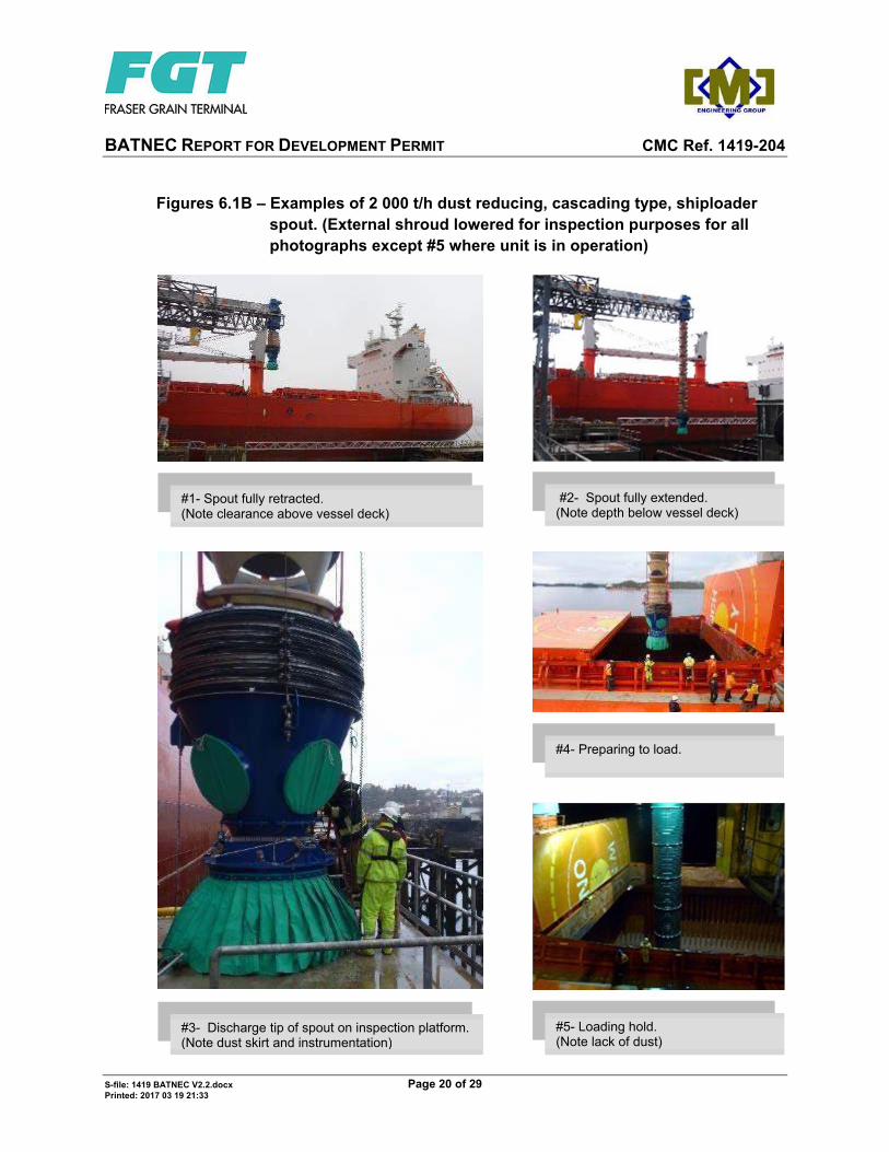
Figures 6.1B – Examples of 2 000 t/h dust reducing, cascading type, shiploader spout. (External shroud lowered for inspection purposes for all photographs except #5 where unit is in operation)
#1- Spout fully retracted. (Note clearance above vessel deck)
#2- Spout fully extended. (Note depth below vessel deck)
#4- Preparing to load.
#5- Loading hold. (Note lack of dust)
#3- Discharge tip of spout on inspection platform. (Note dust skirt and instrumentation)

BATNEC REPORT FOR DEVELOPMENT PERMIT CMC Ref. 1419-204
S-file: 1419 BATNEC V2.2.docx Page 21 of 29 Printed: 2017 03 19 21:33
Cleveland Cascade Limited is well known in North America and their equipment is in use in several British Columbia locations. The spouts are equipped with multiple grain sensors that will be used to control the upwards and downwards motion of the spout tip. The planned method of operation for the shiploader will feature the following steps in order to minimise dust emissions:
# DESCRIPTION OF STEP REMARKS 1 Spout tip is placed in the middle of the hold
and as far down as possible.
2 Flow is started and the spout automatically raises until the spout discharge is clear, while still maintaining the dust skirt contact to the pile of grain.
See Figure 6.1A-1 for example.
3 The process repeated until the pile grows to the top of the hatch thus forming a cone in the hold.
See Figure 6.1A-3 for example.
4 The spout is then moved a few metres horizontally from the centre hatch location.
5 The spout will detect the absence of a grain pile below and will automatically descend until it finds the side of the cone some distance below.
6 Steps 2 and 3 are repeated until a second partial cone is formed next to the main central one.
7 Step 4 is then repeated away from the newly formed peak.
8 Steps 5, 6, and 7 are repeated in various locations in the hold (probably in a horizontal spiral arrangement) until the hold is completely full.
9 If required, the hatch can be levelled by sweeping the spout across the top of the piles. This is usually done at a reduced rate of flow for the sake of accuracy.
BATNEC REPORT FOR DEVELOPMENT PERMIT CMC Ref. 1419-204
S-file: 1419 BATNEC V2.2.docx Page 22 of 29 Printed: 2017 03 19 21:33
# DESCRIPTION OF STEP REMARKS 10 Once the hold is full, the product flow is
stopped, and the shiploader is moved to the next hatch to be filled.
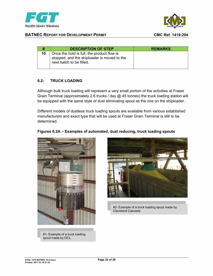
6.2- TRUCK LOADING Although bulk truck loading will represent a very small portion of the activities at Fraser Grain Terminal (approximately 2.6 trucks / day @ 45 tonnes) the truck loading station will be equipped with the same style of dust eliminating spout as the one on the shiploader. Different models of dustless truck loading spouts are available from various established manufacturers and exact type that will be used at Fraser Grain Terminal is still to be determined. Figures 6.2A – Examples of automated, dust reducing, truck loading spouts
#1- Example of a truck loading spout made by DCL.
#2- Example of a truck loading spout made by Cleveland Cascade.
BATNEC REPORT FOR DEVELOPMENT PERMIT CMC Ref. 1419-204
S-file: 1419 BATNEC V2.2.docx Page 23 of 29 Printed: 2017 03 19 21:33
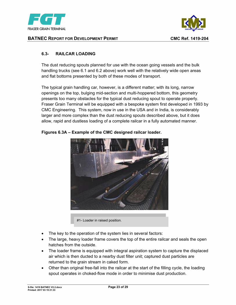
6.3- RAILCAR LOADING The dust reducing spouts planned for use with the ocean going vessels and the bulk handling trucks (see 6.1 and 6.2 above) work well with the relatively wide open areas and flat bottoms presented by both of these modes of transport. The typical grain handling car, however, is a different matter; with its long, narrow openings on the top, bulging mid-section and multi-hoppered bottom, this geometry presents too many obstacles for the typical dust reducing spout to operate properly. Fraser Grain Terminal will be equipped with a bespoke system first developed in 1993 by CMC Engineering. This system, now in use in the USA and in India, is considerably larger and more complex than the dust reducing spouts described above, but it does allow, rapid and dustless loading of a complete railcar in a fully automated manner.
Figures 6.3A – Example of the CMC designed railcar loader.
The key to the operation of the system lies in several factors: The large, heavy loader frame covers the top of the entire railcar and seals the open
hatches from the outside. The loader frame is equipped with integral aspiration system to capture the displaced
air which is then ducted to a nearby dust filter unit; captured dust particles are returned to the grain stream in caked form.
Other than original free-fall into the railcar at the start of the filling cycle, the loading spout operates in choked-flow mode in order to minimise dust production.
#1- Loader in raised position.

BATNEC REPORT FOR DEVELOPMENT PERMIT CMC Ref. 1419-204
S-file: 1419 BATNEC V2.2.docx Page 24 of 29 Printed: 2017 03 19 21:33
6.4- CONTAINER LOADING The loading of standard containers with bulk grain products has been practised for many years. Early facilities used conveyors to fling the grain into the containers (See Photo 6.4.A-1) either with or without partial barriers at the open end of the container. Figures 6.4A – Example of horizontal loading platform
Later variants included tilting the container into to vertical or at an angle (See Photo 6.4.B-1), but in either case the process still has a tendency to produce relatively large quantities of dust due to the use of standard open spouting and a lack of aspiration.
#1- Horizontal loading platform. ( Note dust emissions.)
BATNEC REPORT FOR DEVELOPMENT PERMIT CMC Ref. 1419-204
S-file: 1419 BATNEC V2.2.docx Page 25 of 29 Printed: 2017 03 19 21:33
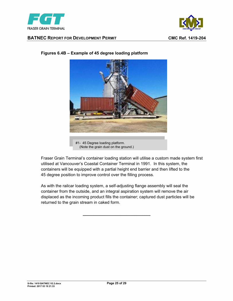
Figures 6.4B – Example of 45 degree loading platform Fraser Grain Terminal’s container loading station will utilise a custom made system first utilised at Vancouver’s Coastal Container Terminal in 1991. In this system, the containers will be equipped with a partial height end barrier and then lifted to the 45 degree position to improve control over the filling process. As with the railcar loading system, a self-adjusting flange assembly will seal the container from the outside, and an integral aspiration system will remove the air displaced as the incoming product fills the container; captured dust particles will be returned to the grain stream in caked form.
_____________________________
#1- 45 Degree loading platform. (Note the grain dust on the ground.)
BATNEC REPORT FOR DEVELOPMENT PERMIT CMC Ref. 1419-204
S-file: 1419 BATNEC V2.2.docx Page 26 of 29 Printed: 2017 03 19 21:33
7- OVERALL PLANT LAYOUT AND ORIENTATION At the onset of the project, PMV informed FGT of the existence of large areas of contaminated soil and groundwater on the site in question. The previous tenant had operated a metal processing facility on the site for several decades and, regrettably, many of the chemicals used in the process had leached into the underground terrain. In order to minimize the risks of disturbing this soil, several design features were included: Excavation and piling were avoided in all areas of concern. This decision required a
change in the overall plant configuration by eliminating the use of large (43 m diameter, 30 000 t) silos and replacing them with smaller (15 m diameter, 3 000 t) silos.
The plant orientation was modified to position the receiving pit (the one required deep excavation) in one of the few areas of the site that was uncontaminated.
Although these two modifications required an increase in the capital expenditures, the end result will produce a significantly lower risk setup both for FGT and for PMV.
_____________________________

BATNEC REPORT FOR DEVELOPMENT PERMIT CMC Ref. 1419-204
S-file: 1419 BATNEC V2.2.docx Page 27 of 29 Printed: 2017 03 19 21:33
8- VISUAL IMPACT 8.1- OVERALL APPEARANCE The majority of the grain handling facilities in the Vancouver harbour as well as the proposed new facility at Lynnterm Westgate are of the monolithic concrete type. In contrast to the formers’ large blocks of silos, Fraser Grain Terminal will utilise individual steel silos. The spaces between the silos along with the open galleries spanning the tops presents a more open and less imposing appearance. Likewise, for Fraser Grain Terminal’s open framed transfer tower in lieu of the more conventional concrete workhouses. The aim is to have as much as possible of the exposed steel elements, be they structural or equipment, made of galvanized steel. Although this procedure requires a slightly higher capital investment, the long term durability of the finish means that there is little or no visual degradation to the physical appearance of the steel over time. In fact, the patina that comes with the aging of the steel is sometimes used as an architectural enhancement. Figures 8.1A – Example of bulk handling facilities using steel silos and open-frame steel structures (all of galvanized steel)
#1- View of high capacity (approximately 3x that of Fraser Grain Terminal) terminal. Silos are approximately the same height as Fraser Grain Terminal’s but are 32.0 m in diameter as opposed to 14.6 m.

BATNEC REPORT FOR DEVELOPMENT PERMIT CMC Ref. 1419-204
S-file: 1419 BATNEC V2.2.docx Page 28 of 29 Printed: 2017 03 19 21:33
8.2- LIGHTING During the night time hours the visual impact of the terminal will be dictated by its lighting. The terminal will be visible to the residents along the hillside to the east of SFPR and to a lesser extent the residents on the Queensborough and New Westminster waterfronts. In order to minimise the effect of the terminal’s lighting system on these surrounding areas the following parameters will be implemented into the design: All outdoor lighting fixtures will be of the LED type. Although this does provide power
savings for FGT, the principle reason for their choice is the better distribution control that these fixtures offer in order to achieve the desirable “dark sky” propagation.
The high pole (≈20 m high) fixtures illuminating the container yard will be turned on to full brightness only when the container yard is in operation.
The lighting in the following areas will be turned on to full brightness only when access is required for repair or inspection: o superstructure (galleries and transfer towers) o ground level area around the silos o container loading area o railcar and truck loading building o rail receiving building.
Figures 8.2A – Examples of typical High Mount LED fixture (CU Phosco)
#1- Close up view of light fixture. #2- Example of installation at Manchester Airport. (Note the lack of upwards diffusion)

BATNEC REPORT FOR DEVELOPMENT PERMIT CMC Ref. 1419-204
S-file: 1419 BATNEC V2.2.docx Page 29 of 29 Printed: 2017 03 19 21:33
Figures 8.2B – Examples of typical LED wall pack fixture (Aimlite)
_____________________________
#1- Close up view of light fixture. #2- Example of installation at warehouse. (Note the sharp light cut-off)