144/ 430 mhz fm dual bander th-f7aion battery pack” {page 2}. 1 position the two grooves on the...
TRANSCRIPT

© B62-1899-00 (M)09 08 07 06 05 04 03 02 01 00
144/ 430 MHz FM DUAL BANDER
TH-F7A
INSTRUCTION MANUAL
FM DUAL BANDER TH-F7

i
THANK YOUTHANK YOUThank you for choosing this KENWOOD TH-F7Atransceiver. It has been developed by a team ofengineers determined to continue the tradition ofexcellence and innovation in KENWOODtransceivers.
First, don’t let the size fool you. This small FMportable transceiver features 2 m and 70 cm amateurradio band operation plus another all-mode 100 kHzto 1.3 GHz receiver (SSB and CW are up to 470MHz). In the meantime, as you learn how to use thistransceiver, you will also find that KENWOOD ispursuing “user friendliness”. For example, each timeyou change the Menu No. in Menu mode, you will seea text message on the display that lets you knowwhat you are configuring.
Though user friendly, this transceiver is technicallysophisticated and some features may be new to you.Consider this manual to be a personal tutorial fromthe designers. Allow the manual to guide you throughthe learning process now, then act as a reference inthe coming years.
FEATURES• Ultra compact design
• 2 m and 70 cm amateur radio band FMtransceiver operation
• A separate wide band, all-mode receiver, built-in
• Dual-frequency receive within the same amateurradio bands
• 400 memory channels plus 34 special functionmemory channels
• Long operation period with a Li-ion battery pack
• High output power (up to 5 W operation)
• Easy to control and select various functions withMulti-scroll key
• 9600 bps Packet-ready data (Speaker/ Mic.) jack
• Built-in VOX function
• Meets MIL-STD 810C/ D/ E, Rain, Humidity,Vibration, and Shock
PRECAUTIONSPlease observe the following precautions to preventfire, personal injury, or transceiver damage:
• Do not transmit with high output power forextended periods. The transceiver may overheat.
• Do not modify this transceiver unless instructed bythis manual or by KENWOOD documentation.
• When using a regulated power supply, connect thespecified DC cable (option) to the DC IN jack onthe transceiver. The supply voltage must bebetween 12 V and 16 V to prevent damaging thetransceiver.
• When connecting the transceiver to a cigarettelighter socket in a vehicle, use the specifiedcigarette lighter cable (option).
• Do not expose the transceiver to long periods ofdirect sunlight nor place the transceiver close toheating appliances.
• Do not place the transceiver in excessively dustyareas, humid areas, wet areas, nor on unstablesurfaces.
• If an abnormal odor or smoke is detected comingfrom the transceiver, turn OFF the powerimmediately and remove the battery case or thebattery pack from the transceiver. Contact yourauthorized KENWOOD dealer, customer service,or service station.
SUPPLIED ACCESSORIESAfter carefully unpacking the transceiver, identify theitems listed in the table below. We recommend youkeep the box and packing material in case you needto repack the transceiver in the future.
yrosseccA rebmuNtraP ytitnauQ
koohtleB XX-3260-92J 1annetnA XX-9870-09T 1
partS XX-2430-96J 1)31-TB(esacyrettaB XX-7393-20A 1
launaMnoitcurtsnI XX-9981-26B 1
WRITING CONVENTIONS FOLLOWEDThe writing conventions described below havebeen followed to simplify instructions and avoidunnecessary repetition.
noitcurtsnI oDottahW
sserP ]YEK[ . esaelerdnasserP YEK .
sserP]1YEK[ , ]2YEK[ .
sserP 1YEK esaeler,yliratnemom1YEK sserpneht, 2YEK .
sserP]YEK[ )s1( .
dlohdnasserP YEK arofnwod.dnoces
sserP]2YEK[+]1YEK[ .
dlohdnasserP 1YEK neht,nwodsserp 2YEK eromeraerehtfI.
dlohdnasserp,syekowtnahtehtlitnunrutniyekhcaenwod
.desserpneebsahyeklanif
sserP][+]YEK[ .
sserp,FFOreviecsnartehthtiWdlohdna YEK NOhctiwsneht,
gnisserpybrewopreviecsnarteht][ .)REWOP(

ii
CONTENTSCHAPTER 6 MEMORY CHANNELSSIMPLEX & REPEATER OR ODD-SPLIT MEMORYCHANNEL? ........................................................... 15
STORING SIMPLEX FREQUENCIES ORSTANDARD REPEATER FREQUENCIES ......... 15STORING ODD-SPLIT REPEATERFREQUENCIES................................................. 15RECALLING A MEMORY CHANNEL ................. 16
Using the Tuning Control or / keys ........... 16Using a Numeric Keypad .............................. 16
CLEARING A MEMORY CHANNEL ................... 16MEMORY RECALL MODE ................................ 16
NAMING A MEMORY CHANNEL........................... 17
MEMORY CHANNEL GROUPS ............................ 18RECALLING A MEMORY CHANNEL USINGMEMORY GROUP FUNCTION ......................... 18ERASING MEMORY CHANNELS USINGMEMORY GROUP DELETE FUNCTION ........... 18
MEMORY CHANNEL TRANSFER ......................... 18MEMORY \ VFO TRANSFER .......................... 18CHANNEL \ CHANNEL TRANSFER ............... 18
CALL CHANNEL.................................................... 19RECALLING THE CALL CHANNEL ................... 19REPROGRAMMING THE CALL CHANNEL ...... 19
INFORMATION CHANNELS.................................. 20REPROGRAMMING THE INFORMATIONCHANNEL ......................................................... 20RECALLING AN INFORMATION CHANNEL ..... 20
CHANNEL DISPLAY .............................................. 20
CHAPTER 7 SCANNORMAL SCAN .................................................... 21
BAND SCAN ..................................................... 21PROGRAM SCAN ............................................. 22
Storing Program Scan Frequency Range ...... 22Performing the Program Scan ....................... 22
MHz SCAN ........................................................ 22
MEMORY SCAN .................................................... 23ALL-CHANNEL SCAN ....................................... 23GROUP SCAN .................................................. 23
Memory Group Link ...................................... 23
CALL SCAN ........................................................... 24
PRIORITY SCAN .................................................... 24PROGRAMMING PRIORITY CHANNELS ......... 24USING PRIORITY SCAN ................................... 24
INFORMATION CHANNEL SCAN ........................... 25
VISUAL SCAN ........................................................ 25USING VISUAL SCAN (VFO) ............................ 25USING VISUAL SCAN(MEMORY CHANNEL) ...................................... 26
MEMORY CHANNEL LOCKOUT ........................... 26
SCAN RESUME METHOD .................................... 26
CHAPTER 8 SELECTIVE CALLCTCSS and DCS ................................................... 27
CTCSS .................................................................. 27USING CTCSS .................................................. 27SELECTING A CTCSS FREQUENCY ............... 27CTCSS FREQ. ID SCAN ................................... 28
THANK YOU............................................................. iFEATURES............................................................... iPRECAUTIONS........................................................ iSUPPLIED ACCESSORIES ..................................... iWRITING CONVENTIONS FOLLOWED .................. iCONTENTS ............................................................. ii
CHAPTER 1 PREPARATIONINSTALLING ALKALINE BATTERIES ...................... 1
INSTALLING THE OPTIONAL Li-ion BATTERY PACK(PB-42L) .................................................................. 1
INSTALLING THE ANTENNA .................................. 1
ATTACHING THE HAND STRAP ............................. 1
INSTALLING THE BELT CLIP .................................. 1
CONNECTING TO A REGULATEDPOWER SUPPLY .................................................... 2
CHARGING THE OPTIONAL Li-ion BATTERYPACK (PB-42L) ........................................................ 2
CONNECTING TO A CIGARETTE LIGHTERSOCKET.................................................................. 2
CHAPTER 2 YOUR FIRST QSOFIRST QSO ............................................................. 3
CHAPTER 3 GETTING ACQUAINTEDKEYS AND CONTROLS .......................................... 4
DISPLAY ................................................................. 5
BASIC OPERATIONSWITCHING POWER ON/ OFF .......................... 6ADJUSTING VOLUME ........................................ 6ADJUSTING SQUELCH ...................................... 6SELECTING A BAND .......................................... 6MULTI-SCROLL KEY........................................... 6TRANSMITTING.................................................. 7
Selecting Output Power .................................. 7SELECTING A FREQUENCY .............................. 7
VFO mode ...................................................... 7MHz mode ...................................................... 7Direct Frequency Entry ................................... 7
CHAPTER 4 MENU SETUPWHAT IS A MENU?.................................................. 9
MENU ACCESS ...................................................... 9
SELECTING A MENU LANGUAGE ......................... 9
MENU FUNCTION LIST .......................................... 9
ALPHABETICAL FUNCTION LIST......................... 11
CHAPTER 5 OPERATING THROUGH REPEATERSOFFSET PROGRAMMING FLOW ......................... 12
PROGRAMMING OFFSET ................................ 12Selecting Offset Direction .............................. 12Selecting Offset Frequency ........................... 12Activating Tone Function ............................... 13Selecting a Tone Frequency .......................... 13
AUTOMATIC REPEATER OFFSET ....................... 13
REVERSE FUNCTION .......................................... 14
AUTOMATIC SIMPLEX CHECK (ASC) .................. 14
TONE FREQ. ID SCAN ......................................... 14
iii
VOX ON BUSY .................................................. 40
CHAPTER 12 OPTIONAL ACCESSORIESOPTIONAL ACCESSORIES .................................. 41
CHAPTER 13 INTERFACING TO PERIPHERALSSP/MIC JACK ........................................................ 42
SELECTING SP/MIC JACK FUNCTION ............ 42SP/MIC ......................................................... 42TNC.............................................................. 42PC ................................................................ 43
CHAPTER 14 TROUBLESHOOTINGGENERAL INFORMATION .................................... 44
SERVICE........................................................... 44SERVICE NOTE ................................................ 44CLEANING ........................................................ 44
BACKUP BATTERY ............................................... 44
TROUBLESHOOTING........................................... 45
MICROPROCESSOR RESET ............................... 47INITIAL SETTINGS ............................................ 47VFO RESET ...................................................... 47MENU RESET ................................................... 47FULL RESET ..................................................... 47PERFORMING RESET ..................................... 47
OPERATION NOTICES ......................................... 48OPERATING VOLTAGE .................................... 48TUNING IN SSB/ CW MODE ............................. 48RECEIVING IN AM BAND ................................. 48RECEIVING SIGNALS IN CITIES ...................... 48BEAT AND NOISE ............................................. 48TRANSMISSION ............................................... 48SUPPLIED ANTENNA ....................................... 48INTERNAL BEATS ............................................ 48
Internal Beats Frequency Formula ................ 49
CHAPTER 15 SPECIFICATIONSSPECIFICATIONS ................................................. 50
CHAPTER 16 APPENDIXTV CHANNELS (VHF) ........................................... 52TV CHANNELS (UHF) ........................................... 53MARINE CHANNELS (VHF) .................................. 54CITIZEN BAND CHANNELS.................................. 54
CHAPTER 17 INDEXINDEX ................................................................... 55
DCS....................................................................... 28USING DCS ...................................................... 28SELECTING A DCS CODE................................ 28DCS CODE ID SCAN ........................................ 29
CHAPTER 9 DTMF FUNCTIONSMANUAL DIALING................................................. 30
DTMF TX HOLD ................................................ 30
AUTOMATIC DIALER ............................................ 30STORING A DTMF NUMBER IN MEMORY ....... 30TRANSMITTING A STORED DTMFNUMBER ........................................................... 31ADJUSTING THE DTMF TONETRANSMISSION SPEED .................................. 31ADJUSTING THE PAUSE DURATION .............. 31
DTMF LOCK .......................................................... 31
CHAPTER 10 UTILIZING THE B-BANDABOUT THE B-BAND ............................................ 32
B-BAND FREQUENCY...................................... 32B-band Frequency Coverage ........................ 32
SELECTING A MODE FOR THE B-BAND ............. 33LSB/ USB/ CW/ AM/ FM/ WFM .......................... 33
BAR ANTENNA ..................................................... 33
FINE TUNING ........................................................ 33ACTIVATING FINE TUNING .............................. 33
Selecting a Fine Tuning Frequency Step ....... 33
CHAPTER 11 OPERATOR CONVENIENCESAPO (Auto Power OFF) ......................................... 34
ATTENUATOR ....................................................... 34
BATTERY LIFE ...................................................... 34
BATTERY REMAINING ......................................... 34BATTERY TYPE ................................................ 34
BATTERY SAVER.................................................. 35
BEAT SHIFT .......................................................... 35
BEEP FUNCTION.................................................. 35
DISPLAY CONTRAST ........................................... 35
FREQUENCY STEP SIZE ..................................... 35
LAMP .................................................................... 36
LOCK FUNCTION ................................................. 36TUNE ENABLE.................................................. 36
MICROPHONE PF KEYS (OPTIONAL) ................. 36
MONITOR ............................................................. 37
NARROW BAND FM OPERATION ........................ 37
POWER-ON MESSAGE ........................................ 37
PROGRAMMABLE VFO ........................................ 37
SINGLE BAND OPERATION ................................. 38
TIME-OUT TIMER ................................................. 38
TONE ALERT ........................................................ 38
TX INHIBIT ............................................................ 38
TX POWER ........................................................... 39
VOLUME BALANCE .............................................. 39
VOX (VOICE OPERATED TRANSMIT) .................. 39VOX GAIN ......................................................... 39VOX DELAY TIME ............................................. 40

1
PREPARATIONINSTALLING ALKALINE BATTERIES1 To open the battery case (BT-13), push the locking
tab in, then pull the cover back.
2 Insert (or remove) 4 AA (LR6) alkaline batteries.
• Be sure to match the battery polarities withthose marked in the bottom of the battery case.
3 Align the two tabs on the battery case cover, thenclose the cover until the locking tabs click.
4 To install the battery case onto (or remove it from)the transceiver, follow steps 1 to 3 of“INSTALLING THE Li-ion BATTERY PACK”above.
Note: When you use the alkaline batteries, access Menu No. 30(BATTERY), then select “ALKALINE”. Otherwise, the batteryremaining cannot be measured correctly page 34.
INSTALLING THE OPTIONAL Li-ionBATTERY PACK (PB-42L)
Note: Because the battery pack is provided uncharged, you mustcharge the battery pack before using it with the transceiver. Tocharge the battery pack, refer to “CHARGING THE OPTIONAL Li-ion BATTERY PACK” page 2.
1 Position the two grooves on the edge and twohooks at the bottom of the battery pack over thecorresponding guides on the back of thetransceiver.
2 Slide the battery pack along the back of thetransceiver until the release latch on the top of thetransceiver locks the battery pack in place.
3 To remove the battery pack, push the release latchon top, then slide the battery pack down.
INSTALLING THE ANTENNAHold the base of the supplied antenna, then screwthe antenna into the connector on the top panel of thetransceiver until secure.
a
ATTACHING THE HAND STRAPIf desired, you can attach the supplied hand strap tothe transceiver.
INSTALLING THE BELT CLIPYou can install the supplied belt clip to the transceivertightening the 2 supplied screws.
Screws
Strap
Tabs
Tab
Grooves
Latch

2
1 PREPARATION
CONNECTING TO A REGULATED POWERSUPPLYTo connect the transceiver to an appropriateregulated power supply, use an optional PG-2WDC cable.
1 Confirm that the power of both the transceiver andthe power supply are OFF.
2 Connect the optional PG-2W DC cable to thepower supply; the red lead to the positive (+)terminal, and the black lead to the negative (–)terminal.
3 Connect the barrel plug on the DC cable tothe DC IN jack of the transceiver.
If the transceiver is turned OFF while a regulatedpower supply is connected with the DC IN jack, itautomatically initiates charging the Li-ion battery pack(PB-42L).
Note:
The supply voltage must be between 12.0 V and 16.0 V toprevent damaging the transceiver. If input voltage exceedsapproximately 16.5 V, warning beeps sound and “VOLTAGEERROR” appears. Remove the DC IN jack plug immediately.
If the DC power supply voltage is above 14.5 V DC and “H”(High Power) is selected, “H” icon blinks and the output poweris reduced to “L” level (Low Power) automatically page 39.
CHARGING THE OPTIONAL Li-ionBATTERY PACK (PB-42L)The Li-ion battery pack can be charged after it hasbeen installed onto the transceiver. The battery packis provided uncharged for safety purposes.
1 Confirm that the transceiver power is OFF.
• While charging the battery pack, leave thetransceiver power OFF.
2 Insert the charger plug into the DC IN jack of thetransceiver.
Note: If the DC power supply voltage is below 12.0 V DC, youmay not be able to charge the Li-ion battery pack (PB-42L).
3 Plug the charger into an AC wall outlet.
• Charging starts and 2 LEDs on the top panellights orange.
4 It takes approximately 6.5 hours to charge anempty PB-42L Li-ion battery pack. When chargingcompletes, the LEDs unlight; remove the chargerplug from the transceiver DC IN jack.
5 Unplug the charger from the AC wall outlet.
Note:
If you turn the transceiver ON and press [F], [LOW/ BATT]while charging the battery pack, “CHARGING” appears.“STANDBY” appears when the charging completes.
The transceiver becomes warm while charging the batterypack.
If the charger plug is plugged into the DC IN jack before thebattery pack is attached, turn the transceiver ON and thenOFF again to initiate the charging.
Exceeding the specified charge period shortens the useful lifeof the Li-ion battery pack.
The provided charger is designed to charge only the providedPB-42L Li-ion battery pack. Charging other modelsof battery packs may damage the charger and battery pack.
Do not press [PTT] while charging. The battery pack must be kept in cool and dry place. Never leave the battery pack in the direct sun light.
CONNECTING TO A CIGARETTE LIGHTERSOCKETTo connect the transceiver to the cigarette lightersocket in your vehicle, use an optional PG-3JCigarette Lighter cable.
Use only the PG-3J, as it has a built in surge protection circuit.Using other cables may cause smoke or fire if there is a voltagesurge.
While the PG-3J is connected to the cigarette lighterplug, the transceiver automatically start charging theLi-ion battery pack (PB-42L). When you operate thetransceiver, it charges the Li-ion battery pack in background. If the transceiver is turned OFF, the 2 LEDslight orange while charging. When the chargingcompletes, they turn OFF.
To connect with an external 24 V power source via a DC-DCconverter, only use the PG-3J. Using the PG-2W or other cablesin this situation may cause smoke or fire.
PG-2W
24V
12V24V PG-3J
12V
12V24V PG-3J
Note: If the input voltage exceeds approximately 16.5 V, warningbeeps sound and “VOLTAGE ERROR” appears.
DC IN jack DC 12 V
Fuses (4 A)
DC IN jack
DC IN jack
DC-DC Converter
DC-DC Converter
Socket
3
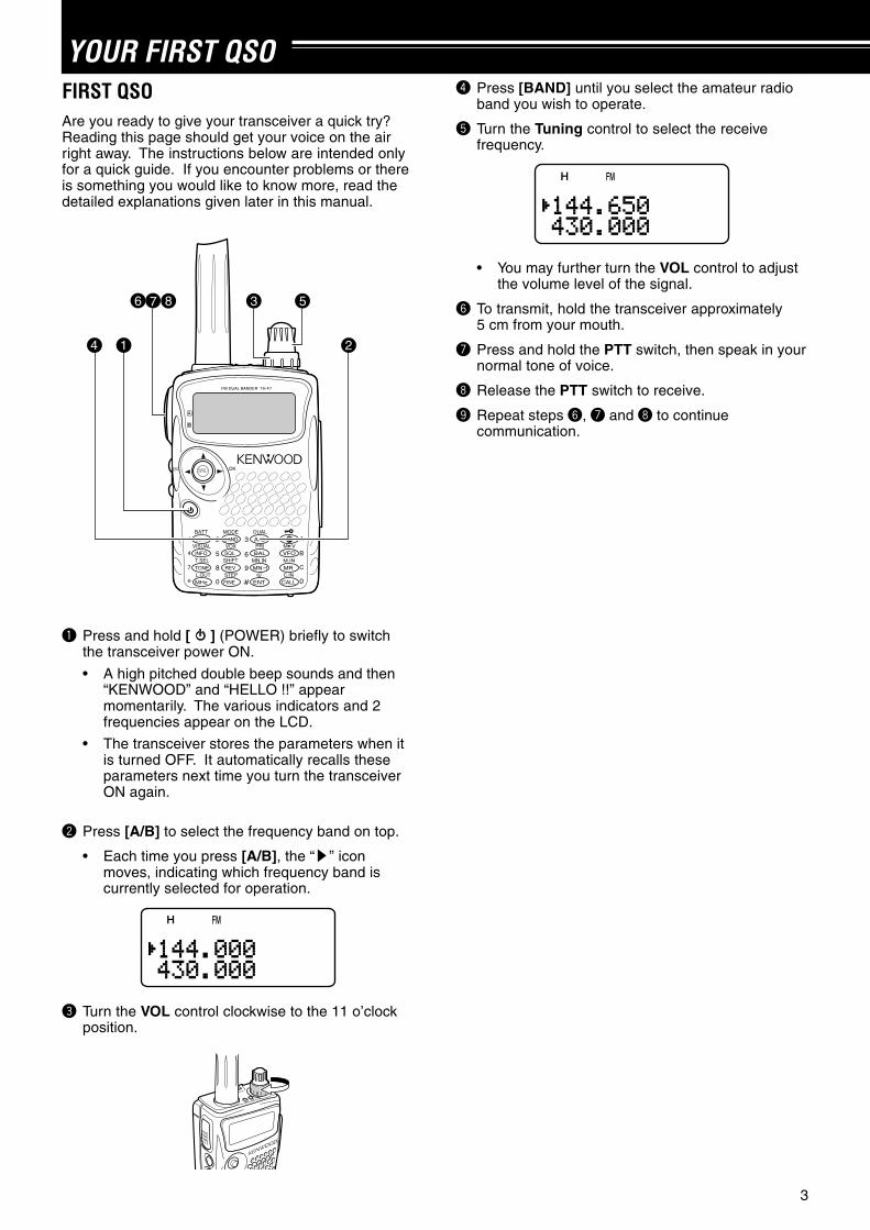
YOUR FIRST QSOFIRST QSOAre you ready to give your transceiver a quick try?Reading this page should get your voice on the airright away. The instructions below are intended onlyfor a quick guide. If you encounter problems or thereis something you would like to know more, read thedetailed explanations given later in this manual.
4
3 5
21
6 7 8
FM DUAL BANDER TH-F7
q Press and hold [ ] (POWER) briefly to switchthe transceiver power ON.
• A high pitched double beep sounds and then“KENWOOD” and “HELLO !!” appearmomentarily. The various indicators and 2frequencies appear on the LCD.
• The transceiver stores the parameters when itis turned OFF. It automatically recalls theseparameters next time you turn the transceiverON again.
w Press [A/B] to select the frequency band on top.
• Each time you press [A/B], the “s” iconmoves, indicating which frequency band iscurrently selected for operation.
e Turn the VOL control clockwise to the 11 o’clockposition.
r Press [BAND] until you select the amateur radioband you wish to operate.
t Turn the Tuning control to select the receivefrequency.
• You may further turn the VOL control to adjustthe volume level of the signal.
y To transmit, hold the transceiver approximately5 cm from your mouth.
u Press and hold the PTT switch, then speak in yournormal tone of voice.
i Release the PTT switch to receive.
o Repeat steps y, u and i to continuecommunication.

4
GETTING ACQUAINTEDKEYS AND CONTROLS
FM DUAL BANDER TH-F7
A/ B-band status LEDsGreen : BusyRed : TransmittingOrange: Charging
Tuning Control
VOL Control
DisplayPTT switch
LAMP Key
Antenna
Speaker/ Mic.
Keypad
Power SwitchMONI Key
M
Multi-scrollKey
SP/MIC jack
DC IN jack
Battery release

5
3 GETTING ACQUAINTED
q EL
Appears when the transmit output power is set to Low(“L”) or Economic Low (“EL”) pages 7, 39.
w H
Appears when the transmit output power is set toHigh (“H”) pages 7, 39.
e LSB
Appears when lower side band (LSB) is selected forB-band page 32.
r USB
Appears when upper side band (USB) is selected forB-band page 32.
t CW
Appears when CW is selected for B-band page 32.
y WFMN
“WFM” appears when wide FM mode is selectedpage 32. “FM” appears when normal FM mode isselected. “FMN” appears when narrow FM mode isselected page 37.
u AM
“AM” appears when AM mode is selected page 32.
i
Appears when a Priority Scan is activated page 24.
o FINE
Appears when a Fine Tuning function is activatedpage 33.
!0 VOX
Appears when the VOX function is activatedpage 39.
!1
Appears when the Automatic Simplex Check (ASC) isactivated page 14.
!2
Appears when the Lock function is ON page 36.
!3
Appears when the function key is pressed.
!4
S-meter (RX) and relative RF power meter (TX).
!5 CT
“CT” appears when the CTCSS function is activatedpage 27.
!6
Appears when the Tone function is activatedpage 13.
!7 DCS
Appears when the DCS function is activatedpage 29.
!8 +/ –/
Appears when the repeater shift function is activatedpage 12.
!9 R
Appears when the Reverse function is activatedpage 14.
@0
Appears when the Tone Alert function is activatedpage 38.
@1
Appears when the displayed memory channel hasbeen locked out page 26.
@2 Dot-matrix display
76 x 16 dot-matrix display. It displays variousinformation, such as the operating frequencies, menusettings, and etc.
DISPLAY
14
1
15
21
22
2 3 4 5 6 7 8 9 10 11 12 13
16 17 18 19 20

6
3 GETTING ACQUAINTED
BASIC OPERATIONSWITCHING POWER ON/ OFF
1 Press [ ] (POWER) briefly to switch thetransceiver power ON.
• Upon power up, a high pitched double beepsounds, followed by the frequencies and otherindicators.
2 To switch the transceiver OFF, press [ ](POWER) again.
• When you turn the transceiver OFF, a lowpitched double beep sounds.
• The transceiver stores the parameters when itis turned OFF. It recalls these parameters nexttime you turn the transceiver ON again.
ADJUSTING VOLUMETurn the VOL control clockwise to increase the audiooutput level and counterclockwise to decrease theoutput level.
• If you are not receiving a signal, press and hold[MONI] to unmute the speaker, then adjust theVOL control to a comfortable audio output level.
ADJUSTING SQUELCHThe purpose of the Squelch is to mute the speakerwhen no signals are present. With the squelch levelcorrectly set, you will hear sound only while actuallyreceiving signals. The higher the selected squelchlevel, the stronger the signals must be, to receive.The appropriate squelch level depends on theambient RF noise conditions. You can configureindependent threshold squelch levels for the A-bandand B-band.
1 Press [SQL].
• The current squelch level appears.
2 Turn the Tuning control or press [ ]/ [ ] to adjustthe level.
• Select the level at which the background noiseis just eliminated when no signal is present.
• The higher the level, the stronger the signalsmust be, to receive.
• 6 different levels can be set (-- -- -- -- --: level 0 ~ || || || || ||: level 5).
3 Press [ ] or [MNU] to store the new settings orpress [ ] to cancel without changing the currentsetting.
Note: When operating in USB, LSB and CW modes, the squelchunmutes up to level 2.
SELECTING A BANDBy default, two frequencies are displayed on theLCD. The frequency on top is called the A-band. Thebottom frequency is called the B-band.
Press [A/B] to select the A-band or B-band foroperation. Each time you press [A/B], the “s” iconmoves, indicating which band is currently selected foroperation. Usually, select the A-band to operate theamateur band and select the B-band to receive thevarious broadcasting stations, such as AM, FM, TV(audio only) or another amateur band page 33.
MULTI-SCROLL KEYThis transceiver has a 4-way cursor key with a MENU(“MNU”) key in the center.
/ keys
The / keys function in the same way as theTuning control. These keys change the frequencies,memory channels, and other selections.
Note: You can use the Tuning control in place of the / keysfor most of the controls.
/ OK key
Press to move to the next step or complete thesetting in various modes, such as Menu mode,CTCSS frequency selection, and DCS code selection.
/ ESC key
Press to move back or cancel the entry in variousmodes, such as Menu mode, CTCSS frequencyselection, and direct frequency entry.
MNU key
Press to enter the Menu mode.
In Menu mode, you can select the desired menunumber by turning the Tuning control or pressing[ ]/ [ ]. It also functions as [OK] key.
B-band
A-band

7
3 GETTING ACQUAINTED
TRANSMITTING1 To transmit, hold the transceiver approximately
5 cm (2 inches) from your mouth, then press andhold the PTT switch and speak into themicrophone in your normal tone of voice.
• The status LED on the top panel lights red andbar-graph meter appears.
• If you press [PTT] while you are outside of thetransmission coverage, a high pitched errorbeep sounds.
2 When you finish speaking, release the PTT switch.
Note: If you transmit continuously for more than 10 minutes, theinternal time-out timer generates a warning beep and thetransceiver stops transmitting. In this case, release the PTTswitch and let the transceiver cool down for a while, then pressthe PTT switch again to resume transmitting pages 38, 48.
Selecting Output Power
Selecting lower transmission power is the bestway to reduce the battery consumption, ifcommunication is still reliable. You can configuredifferent power levels for transmission page 39.
Press [LOW].
• Each time you press [LOW], the indicatorcycles between “H” (high), “L” (low), and “EL”(economic low).
Note:
You can store different output power setting for the A and B-band.
When you change the output power, it is reflected to allavailable amateur bands for A or B-band.
SELECTING A FREQUENCY VFO Mode
This is the basic mode for changing the operatingfrequency. Turn the Tuning control clockwise toincrease the frequency. Turn the Tuning controlcounterclockwise to decrease the frequency. Or,press [ ]/ [ ] to change the frequency.
MHz Mode
If the desired operating frequency is far away fromthe current frequency, it is quicker to use the MHztuning mode.
To adjust the MHz digit:
1 Press [MHz].
• A MHz digit blinks.
2 Turn the Tuning control or press [ ]/ [ ] toselect the desired MHz digit.
3 After selecting the desired MHz digit, press[MHz] to exit the mode and return to normalVFO mode above.
4 You may further adjust the frequency using theTuning control or [ ]/ [ ].
Note: MHz mode does not function in AM band.
Direct Frequency Entry
In addition to turn the Tuning control or press[ ]/ [ ], there is another way of selecting thefrequency. When the desired frequency is faraway from the current frequency, you can directlyenter a frequency from the numeric keypad.
1 Press [VFO].
• You must be in the VFO mode to make thedirect frequency entry.
2 Press [ENT].
• “– – – – – –” appears.
3 Press the numeric keys ([0] to [9]) to enteryour desired frequency. [MHz] can be used tocomplete the MHz digits entry.
• Pressing [ENT] fills the remaining digits (thedigits you did not enter) with 0 andcompletes the entry.
• To select 145.000 MHz for example, press[1], [4], [5] then press [ENT] to completethe entry.
• If you want to revise the MHz digits only,press [VFO] in place of [ENT].

8
3 GETTING ACQUAINTED
Example 1 (100 MHz < f < 1000 MHz)
To enter 438.320 MHz:
Key in Display
[ENT] – – – – – –
[4], [3], [8] 4 3 8. – – –
[3], [2], [0] 4 3 8. 3 2 0
Note: You do not have to press [MHz] when you are entering3-digit MHz number.
Example 2
To enter 439.000 MHz:
Key in Display
[ENT] – – – – – –
[4], [3], [9] 4 3 9. – – –
[ENT] 4 3 9. 0 0 0
Example 3
To revise 144.650 MHz to 145.650 MHz:
Key in Display
1 4 4. 6 5 0
[ENT] – – – – – –
[1], [4], [5] 1 4 5. – – –
[VFO] 1 4 5. 6 5 0
Example 4 (f > 1000 MHz)
To enter 1250.500 MHz (B-band only):
Key in Display
[ENT] – – – – – –
[1], [2], [5], [0] 12 5 0. – – –
[5] 12 5 0. 5 – –
[ENT] 12 5 0. 5 0 0
Example 5 (f < 100 MHz)
To enter 10.500 MHz (B-band only):
Key in Display
[ENT] – – – – – –
[1], [0] 1 0 – – – –
[MHz] 1 0. – – –
[5] 1 0. 5 – –
[ENT] 1 0. 5 0 0 0
Note: When pressing the last [ENT], the Fine Tuning functionis automatically activated for 10.5000 MHz.
Example 6
To enter 810 kHz (B-band only):
Key in Display
[ENT] – – – – – –
[0] 0 – – – – –
[MHz] 0. – – –
[8], [1], [0] 0. 8 1 0
Note:
If the entered frequency does not match the current frequencystep size, the frequency is automatically rounded down to thenext available frequency.
When the desired frequency cannot be entered exactly, checkwhether the Fine Tuning function is ON or notpage 33, and then confirm the frequency step sizepage 35.
Some frequency ranges are blocked, due to governmentregulations. Refer to the specifications pages 50, 51 for theTX/ RX coverage.
If you turn the Tuning control or press [ ]/ [ ] while enteringthe frequency, the transceiver clears the entry and recoversthe previous frequency and mode.

9
MENU SETUPWHAT IS A MENU?Many functions on this transceiver are selected orconfigured via a software-controlled Menu, ratherthan through the physical controls of the transceiver.Once familiar with the Menu system, you willappreciate the versatility it offers. You can customizethe various timings, settings, and programmingfunctions on this transceiver to meet your needswithout using many controls and switches.
MENU ACCESS1 Press [MNU].
• The Menu No. and setting appear on thedisplay, along with a brief explanation of theMenu No.
2 Turn the Tuning control or press [ ]/ [ ] to selectyour desired Menu No.
• As you change the Menu No., a briefexplanation of each Menu No. appears.
3 Press [ ] or [MNU] to configure the parameter ofthe currently selected Menu No.
4 Turn the Tuning control or press [ ]/ [ ] to selectyour desired parameter.
5 Press [ ] or [MNU] to store the setting.Otherwise, press [ ] or [PTT] to cancel.
MENU FUNCTION LIST
SELECTING A MENU LANGUAGEYou can select either English or Japanese (Katakana)for the menu description. To switch the language:
1 Press [MNU].
2 Turn the Tuning control or press [ ]/ [ ] to selectMenu No. 27.
3 Press [ ] or [MNU].
4 Turn the Tuning control or press [ ]/ [ ] to selecteither “ENGLISH” or “JAPANESE”.
5 Press [ ] or [MNU] to store the setting.Otherwise, press [ ] or [PTT] to cancel.
• When you select “JAPANESE” in step 3 andpress [ ] or [MNU], all Menu explanations aredisplayed in Japanese (Katakana). To return toEnglish mode, repeat step 1, 2 and 3 aboveto access Menu No. 27, then select“ENGLISH”. Press [ ] or [MNU] to display theMenu mode in English.
Note: The menu language selection does not affect any othermodes, such as memory name page 17 or DTMF name page31.
yalpsiDehtnO uneM.oN noitcnuF snoitceleS tluafeD .feR
gaP e
EMUSERNACS 1
dohtememusernacSedomdetarepO-emiT:EMIT
edomdetarepO-reirraC:REIRRACedompotsdnakeeS:KEES
/REIRRAC/EMITKEES
EMIT 62
KNILPRG.M 2 noitarugifnockniLpuorGyromeM 76543210 skniLoN 32
DOHTEMRM 3 noitidnocllaceRyromeM/SDNABLLA
DNABTNERRUCLLA
SDNAB61
OFVGORP 4egnarycneuqerfOFVelbammargorP
)ylnodnab-A(—
eeSecnerefeR
egaP73
TESFFOOTUA 5 noitcnuftesffOretaepeRotuA FFO/NO NO 31
TESFFO 6 ycneuqerftesfforetaepeRzHM59.95~00.0
fospetsnizHM50.0
eeSecnerefeR
egaP21
ELBANEENUT 7ehtfoesutimreP gninuT syekehtnehwlortnoc
dekcoleraFFO/NO FFO 63
TIBIHNIXT 8 noissimsnartehttibihnI FFO/NO FFO 83
KCAJCIM/PS 9 ehttceleS CIM/PS noitcnufkcaj CP/CNT/CIM/PS CIM/PS2434

10
4 MENU SETUP
yalpsiDehtnO uneM.oN noitcnuF snoitceleS tluafeD .feR
gaP e
EROTSFMTD 01 seiromemFMTDnisrebmunFMTDerotS — ataDoN 03
DPSFMTD 11 deepsnoissimsnartenotFMTD WOLS/TSAF TSAF 13
DLOHFMTD 21neewtebsdnoces2rofnoissimsnartehtdloH
seirtneyekFMTDFFO/NO FFO 03
ESUAPFMTD 31FMTDgnittimsnartelihwnoitarudesuapehT
senot
/005/052/001/0051/0001/057
sm0002sm005 13
KCOLFMTD 41 syekhtiwnoissimsnartFMTDelbasiD FFO/NO FFO 13
GSMNO-RWP 51 egassemno-rewoP sretcarahc8 !!OLLEH 73
TSARTNOC 61tsartnocyalpsidDCL
mumixam:61~muminim:161~1 8 53
REVASTAB 71 doirepffo-tuhsreviecerrevasyrettaB/6.0/4.0/2.0/FFO
/0.3/0.2/0.1/8.0.ces0.5/0.4
.ces0.1 53
OPA 81 noitcnufffOrewoPcitamotuA .nim06/03/FFO .nim03 43
PEEBYEK 91 noitcnufpeeB FFO/NO NO 53
YSUBnoXOV 02sireviecerehtnehwnoissimsnartXOVwollA
ysubFFO/NO FFO 04
NIAGXOV 12ytivitisnesniagXOVehtteS
evitisnestsom:9~evisitnestsael:09~0 4 93
YALEDXOV 22 emityaledXOVehttsujdA/057/005/052
/0002/0051/0001sm0003
sm005 04
YEKLLAC 32 yekLLACehtrofnoitcnufatceleS zH0571/LLAC LLAC 91
DLOH0571 42sienotzH0571anehwsutatsXTehtdloH
dettimsnartFFO/NO FFO 31
TFIHSTAEB 52 ycneuqerfkcolcUPClanretniehttfihS FFO/NO FFO 53
TNARAB 62 zHM1.01wolebannetnarablanretninaelbanE/DELBANE
DELBASIDDELBANE 33
EGAUGNAL 72 egaugnalunemehttceleS/HSILGNEESENAPAJ
HSILGNE 9
TEKCAP 82 deepstekcapCNTlanretxenatceleS spb0069/0021 spb0021 24
WORRANMF 92 noitarepodnabworranMF FFO/NO FFO 73
YRETTAB 03 epytyrettabatceleS/MUIHTILENILAKLA
MUIHTIL 43
?TESER 13 edomteseratceleS/TESEROFV/ON
/TESERUNEMTESERLLUF
ON 74

11
4 MENU SETUP
yalpsiDehtnO .oNuneM snoitceleS tluafeD gaP.feR e
OPA 81 setunim06/03/FFO .nim03 43
TESFFOOTUA 5 FFO/NO NO 31
TNARAB 62 DELBASID/DELBANE DELBANE 33
YRETTAB 03 ENILAKLA/MUIHTIL MUIHTIL 43
REVASTAB 71 .ces0.5/0.4/0.3/0.2/0.1/8.0/6.0/4.0/2.0/FFO .ces0.1 53
TFIHSTAEB 52 FFO/NO FFO 53
YEKLLAC 32 zH0571/LLAC LLAC 91
TSARTNOC 61 61~1 8 53
DLOHFMTD 21 FFO/NO FFO 03
KCOLFMTD 41 FFO/NO FFO 13
ESUAPFMTD 31 sm0002/0051/0001/057/005/052/001 sm005 13
DPSFMTD 11 WOLS/TSAF TSAF 13
EROTSFMTD 01 — ataDoN 03
WORRANMF 92 FFO/NO FFO 73
PEEBYEK 91 FFO/NO NO 53
EGAUGNAL 72 ESENAPAJ/HSILGNE HSILGNE 9
DOHTEMRM 3 DNABTNERRUC/SDNABLLALLA
SDNAB61
KNILPRG.M 2 76543210 skniLoN 32
TESFFO 6 zHM50.0fospetsnizHM59.95~00.0eeS
ecnerefeRegaP
21
TEKCAP 82 spb0069/0021 spb0021 24
OFVGORP 4 — — 73
GSMNO-RWP 51 sretcarahc8 !!OLLEH 73
?TESER 13 TESERLLUF/TESERUNEM/TESEROFV/ON ON 74
EMUSERNACS 1 KEES/REIRRAC/EMIT EMIT 62
KCAJCIM/PS 9 CP/CNT/CIM/PS CIM/PS 34,24
ELBANEENUT 7 FFO/NO FFO 63
TIBIHNIXT 8 FFO/NO FFO 83
YALEDXOV 22 sm0003/0002/0051/0001/057/005/052 sm005 04
NIAGXOV 12 9~0 4 93
YSUBnoXOV 02 FFO/NO FFO 04
DLOH0571 42 FFO/NO FFO 31
ALPHABETICAL FUNCTION LIST

12
OPERATING THROUGH REPEATERSRepeaters, which are often installed and maintainedby radio clubs, are usually located on mountain topsor other elevated locations. Generally they operate athigher ERP (Effective Radiated Power) than a typicalstation. This combination of elevation and high ERPallows communications over much greater distancesthan communications without using repeaters.
Most repeaters use a receive and transmit frequencypair with a standard or non-standard offset (odd-split).In addition, some repeaters must receive a tone fromthe transceiver to allow it to access. For details,consult your local repeater reference.
OFFSET PROGRAMMING FLOW
If you store the above data in a memory channel, youneed not reprogram every time. See “MEMORYCHANNELS” page 15.
PROGRAMMING OFFSETFirst select an amateur radio repeater downlinkfrequency on the A-band or B-band as described in“SELECTING A FREQUENCY” page 7.
Selecting Offset Direction
Select whether the transmit frequency will behigher (+) or lower (–) than the receive frequency.
Press [F], [REV] to select the offset direction.
• “+” or “–” appears, indicating which offsetdirection is selected.
• To program –7.6 MHz offset on the TH-F7A(430 MHz only), repeatedly press [F], [REV]until “ ” appears.
If the offset transmit frequency falls outside theallowable range, transmitting is inhibited. In thiscase, adjust the receive frequency so that thetransmit frequency is within the band limits.
Note: While using an odd-split memory channel ortransmitting, you cannot change the offset direction.
Selecting Offset Frequency
To access a repeater which requires an odd-splitfrequency pair, change the offset frequency fromthe default which is used by most repeaters. Thedefault offset frequency on the 2 m band is600 kHz; the default on the 70 cm band is 1.6MHz.
1 Press [BAND] to select an amateur radio bandyou want to change the offset frequency.
2 Press [MNU].
3 Turn the Tuning control or press [ ]/ [ ] toselect Menu No. 6 (OFFSET).
4 Press [ ] or [MNU].
5 Turn the Tuning control or press [ ]/ [ ] toselect the appropriate offset frequency.
• The selectable range is from 0.00 MHz to59.95 MHz in steps of 50 kHz.
6 Press [ ] or [MNU] to store the setting.Otherwise, press [PTT] to cancel.
Note:
If you have selected “ ” for the offset direction, you cannotchange the default (–7.6 MHz) offset frequency.
After changing the offset frequency, the new offset frequencywill also be used by Automatic Repeater Offset.
TX: 144.725 MHzTX tone: 88.5 HzRX: 145.325 MHz TX: 144.725 MHz
TX tone: 88.5 HzRX: 145.325 MHz
Select a band.q
w
e
r
t
y
Select a receive frequency.
Select an offset direction.
Select an offset frequency (only when programming odd-split repeater frequencies).
Activate the Tone function(if necessary).
Select a tone frequency (if necessary).

13
5 OPERATING THROUGH REPEATERS
Activating Tone Function
Press [TONE] to switch the Tone function ON (orOFF).
• “ ” appears when the Tone function is ON.
Note:
You cannot use the Tone and CTCSS/ DCS functions at thesame time. Switching the Tone function ON after activatingthe CTCSS/ DCS deactivates the CTCSS/ DCS function.
When you access repeaters that require 1750 Hz tones, youneed not activate the Tone function. Press [CALL] withoutpressing the PTT switch to transmit a 1750 Hz tone (defaultsetting).
Selecting a Tone Frequency
1 While the Tone function is ON, press [F],[TONE].
2 Turn the Tuning control or press [ ]/ [ ] toselect the desired tone frequency.
3 Press [ ] or [MNU] to complete the setting.Otherwise, press [PTT] to cancel.
Available Tone Frequencies
.oN .qerF)zH( .oN .qerF
)zH( .oN .qerF)zH( .oN .qerF
)zH(
10 0.76 21 4.79 32 3.141 43 5.602
20 3.96 31 0.001 42 2.641 53 7.012
30 9.17 41 5.301 52 4.151 63 1.812
40 4.47 51 2.701 62 7.651 73 7.522
50 0.77 61 9.011 72 2.261 83 1.922
60 7.97 71 8.411 82 9.761 93 6.332
70 5.28 81 8.811 92 8.371 04 8.142
80 4.58 91 0.321 03 9.971 14 3.052
90 5.88 02 3.721 13 2.681 24 1.452
01 5.19 12 8.131 23 8.291
11 8.49 22 5.631 33 5.302
Note:
42 different tones are available for the transceiver. These 42tones includes 37 EIA standard tones and 5 non-standardtones.
To transmit a 1750 Hz tone, simply press [CALL] withoutpressing the PTT switch (default setting). Release [CALL] toquit transmitting. You can also make the transceiver remain inthe transmit mode for 2 seconds after releasing [CALL]; a1750 Hz tone is not continuously transmitted. Access MenuNo. 24 (1750 HOLD) and select “ON”.
If you desire to assign [CALL] for recalling the Call channel inplace of transmitting the 1750 Hz tone, access MenuNo. 23 (CALL KEY) and select “CALL”.
AUTOMATIC REPEATER OFFSETThis function automatically selects an offset direction,according to the frequency that you select on the2 m band. The transceiver is programmed for offsetdirection as shown below. To obtain an up-to-dateband plan for repeater offset direction, contact yournational Amateur Radio association.
SS
S: Simplex
–
144.0 146.0 MHz145.8145.6
Note: Automatic Repeater Offset does not function whenReverse is ON. However, pressing [REV] after AutomaticRepeater Offset has selected an offset (split) status, exchangesthe receive and transmit frequencies.
1 Press [MNU].
2 Turn the Tuning control or press [ ]/ [ ] to selectMenu No. 5 (AUTO OFFSET).
3 Press [ ] or [MNU].
4 Turn the Tuning control or press [ ]/ [ ] switchthe function ON or OFF.
5 Press [ ] or [MNU] to store the setting.Otherwise, press [PTT] to cancel.
Note: If you select the frequency within the amateur radio bandon the B-band, the Automatic Repeater Offset function is alsoactivated in any modes.

5 OPERATING THROUGH REPEATERS
14
REVERSE FUNCTIONThe reverse function exchanges a separate receiveand transmit frequency. So, while using a repeater,you can manually check the strength of a signal thatyou receive directly from the other station. If thestation’s signal is strong, both stations should moveto a simplex frequency and free up the repeater.
To swap the transmit and receive frequencies:
Press [REV] to switch the Reverse function ON (orOFF).
• “R” appears when the function is ON.
Note: You can turn the Reverse function ON when you areoperating in Simplex mode. However, it does not change the TX/RX frequency.
AUTOMATIC SIMPLEX CHECK (ASC)While using a repeater, the ASC function periodicallychecks the strength of a signal that you are receivingdirectly from the other station. If the station’s signal isstrong enough to allow direct contact without arepeater, “ ” indicator on the display starts blinking.
Press [REV] (1 s) to switch the function ON.
• “ ” appears when the function is ON.
• While direct contact is possible, “ ” blinks.
• To quit the function, press [REV].
Note:
Pressing the PTT switch causes “ ” icon to quit blinking. ASC can be activated while operating in Simplex mode.
However, it does not change the TX/ RX frequencies. ASC does not function while scanning. Activating ASC while using Reverse switches Reverse OFF. If you recall a memory channel or the Call channel that
contains a Reverse ON status, ASC is switched OFF. ASC causes received audio to be momentarily intermitted
every 3 seconds. ASC does not function when the band is not selected for
operation.
TONE FREQ. ID SCANThis function scans through all tone frequencies toidentify the incoming tone frequency on a receivedsignal. You may use the function to find which tonefrequency is required by accessing your localrepeater.
1 While the Tone function is ON, press [F],[TONE] (1 s) to start the Tone Freq. ID scan.
• When the transceiver receives the signal, thescan starts.
• To reverse the scan direction, turn the Tuningcontrol or press [ ]/ [ ].
• To quit the function, press [PTT] or [ ].
• When the tone frequency is identified, a beepsounds and the identified frequency appears.
2 Press [ ] to program the identified frequency inplace of the current tone frequency.
• Press [ ] if you do not want to program theidentified frequency.
• Press [ ]/ [ ] while the identified frequency isblinking, to resume scanning.
Note: Some repeaters do not re-transmit the access tone in thedownlink signal. In this case, check the other station’s uplinksignal to detect the repeater access tone.
144.
725
MH
z
145.325 MH
z
144.725 MHz
TX: 144.725 MHz TX: 144.725 MHz TX: 144.725 MHz TX: 145.325 MHzRX: 145.325 MHz RX: 145.325 MHz RX: 145.325 MHz RX: 144.725 MHz

15
MEMORY CHANNELSIn memory channels, you can store frequencies andrelated data that you often use. Then you need notreprogram those data every time. You can quicklyrecall a programmed channel through simpleoperation. A total of 400 memory channels areavailable for storing the frequencies, modes andother operating conditions of the A and B-bands.
SIMPLEX & REPEATER ORODD-SPLIT MEMORY CHANNEL?You can use each memory channel as a simplex &repeater channel or an odd-split channel. Store onlyone frequency to use as a simplex & repeaterchannel or two separate frequencies to use as anodd-split channel. Select either application for eachchannel depending on the operations you have inmind.
Simplex & repeater channels allow:
• Simplex frequency operation
• Repeater operation with a standard offset(if an offset direction is stored)
Odd-split channels allow:
• Repeater operation with a non-standard offset
Note: Not only can you store data in memory channels, but youcan also overwrite existing data with new data.
The data listed below can be stored in each memorychannel:
retemaraP &xelpmiSretaepeR tilpS-ddO
ycneuqerfevieceRseY
seY
ycneuqerftimsnarT seY
ycneuqerfenoT seY seY
NOenoT seY seY
ycneuqerfSSCTC seY seY
NOSSCTC seY seY
edocSCD seY seY
NOSCD seY seY
noitceridtesffO seY A/N
ycneuqerftesffO seY A/N
NOesreveR seY A/N
ezispetsycneuqerF seY seY
tuokcollennahcyromeM seY seY
emanlennahcyromeM seY seY
NOgninutENIF seY seY
noitcelesedoM seY seY
Yes: Can be stored in memory.N/A: Cannot be stored in memory.
Note: The transmit frequency must be on the same band as thereceive frequency band (Odd-split channel).
STORING SIMPLEX FREQUENCIES ORSTANDARD REPEATER FREQUENCIES1 Press [VFO].
2 Turn the Tuning control or press [ ]/ [ ] to selectyour desired frequency in the amateur radiobands.
• You can also directly enter desired frequencyusing the keypad page 7.
3 If storing a standard repeater frequency, select thefollowing data:
• Offset direction page 12• Tone function, if necessary page 13• CTCSS/ DCS function, if necessary
pages 28, 29
If storing a simplex frequency, you may selectother related data (CTCSS or DCS settings, etc.).
4 Press [F].
• A memory channel number appears and blinks.
• “ ” indicates the current channel is empty; “ ”appears if the channel contains data.
• Memory channel number L0/U0 ~ L9/U9page 23, I–0 ~ I–9 page 20, and Pr1 andPr2 page 25 are reserved for other functions.
5 Turn the Tuning control or press [ ]/ [ ] to selectthe memory channel in which you want to storethe data.
6 Press [MR] ([ ] or [MNU]) to store the data to thechannel.
STORING ODD-SPLIT REPEATER FREQUENCIESSome repeaters use a receive and transmit frequencypair with a non-standard offset. If you store twoseparate frequencies in a memory channel, you canoperate on those repeaters without programming theoffset frequency and direction.
1 Store the desired receive frequency and relateddata by the procedure given for simplex orstandard repeater frequencies above.
2 Turn the Tuning control or press [ ]/ [ ] to selectthe desired transmit frequency.
3 Press [F].
4 Turn the Tuning control or press [ ]/ [ ] to selectthe memory channel you programmed in step 1.
5 Press [PTT]+[MR] ([PTT]+[ ] or [PTT]+[MNU]).
• The transmit frequency is stored in the memorychannel.
Note:
When you recall an odd-split memory channel, “+” and “–”appear on the display. To confirm the transmit frequency,press [REV].

16
6 MEMORY CHANNELS
When you revise only the transmission frequency for the odd-split channel, the frequency step size must be the same asthe original odd-split channel memory data.
RECALLING A MEMORY CHANNELThere are 2 ways of recalling the desired memorychannel.
Using the Tuning Control or / Keys
1 Press [MR] to enter Memory Recall mode.
• The memory channel used last is recalled.
2 Turn the Tuning control or press [ ]/ [ ] toselect your desired memory channel.
• You cannot recall an empty memorychannel.
• To restore VFO mode, press [VFO].
Note: If the “CURRENT BAND” is selected for Menu No. 3(MR METHOD), only memory channels that have the sameband data can be recalled below.
Using a Numeric Keypad
You can also recall a memory channel by enteringa desired memory channel number with thekeypad.
1 Press [MR] to enter Memory Recall mode.
2 Press [ENT], then enter the channel numberusing 3 digits.
• For example, to recall channel 12, press[ENT], [0], [1], [2].
• You can shorten the entry for memorychannels that are less than 100 by pressing[ENT] after entering the channel number.For example, to recall memory channel 9,press [ENT], [9], [ENT].
Note:
You cannot recall an empty memory channel. An error beepsounds.
You cannot recall the Program Scan memory channels(L0/U0 ~ L9/U9), Priority channels (Pr1 and Pr2), andInformation Channels (I–0 ~ I–9), using the numeric keypad.
When you recall an odd-split memory channel, “+” and “–”appear on the display. Press [REV] to display the transmitfrequency.
After recalling a memory channel, you may modify data suchas Tone or CTCSS. These settings, however, are clearedonce you select another channel or the VFO mode. Topermanently store the data, overwrite the channel contentspage 15.
CLEARING A MEMORY CHANNELTo clear an individual memory channel:
1 Recall the memory channel you want to erase.
2 Press and hold [ ] (POWER) to switch thetransceiver OFF.
3 Press [MR]+[ ] (POWER).
• An erase confirmation message appears.
4 Press [MR] ([ ] or [MNU]) to erase the channeldata.
• The contents of the memory channel areerased.
• To quit clearing the memory channel, press anykey other than [MR], [ ] and [MNU].
Note:
If you clear the information channel data, the data will be setto the factory default values.
You can also clear the Priority channel data and L0/U0 ~ L9/U9 data.
To clear all memory channels contents, perform the Full Resetpage 47.
MEMORY RECALL MODESince the transceiver has more than 400 memorychannels, it sometimes takes time to search for yourdesired memory channel. By default, the transceivercan recall all memory channels when [MR] ispressed, regardless of the current operating band.However, you can configure the transceiver to recallonly the memory channels that have the same bandinformation. For example, when you operate on the2 m band in VFO mode, pressing [MR] recalls onlythe memory channels that have 2 m bandinformation. To change the memory recall mode:
1 Press [MNU].
2 Turn the Tuning control or press [ ]/ [ ] to selectMenu No. 3 (MR METHOD).
3 Press [ ] or [MNU].
4 Turn the Tuning control or press [ ]/ [ ] to select“CURRENT BAND”.
5 Press [ ] or [MNU] to store the setting.Otherwise, press [ ] or [PTT] to cancel.
When you press [MR] in VFO mode, only memorychannels that have the same band data are recalled.To return to the default memory recall mode, repeatstep 1 to 5 above and select “ALL BANDS” instep 4.
Note:
All Information Channels are recalled regardless of MemoryRecall mode selection.
Memory Recall mode selection does not change the MemoryGroup scan channels page 23 .

17
6 MEMORY CHANNELS
NAMING A MEMORY CHANNELYou can name memory channels using up to 8alphanumeric characters. When you recall a namedmemory channel, its name appears on the display inplace of the stored frequency. Names can be callsigns, repeater names, cities, names of people, etc.
1 Press [MR] to recall your desired memorychannel.
2 Press [F], [MN<->f] to enter memory name inputmode.
• The entry cursor appears.
3 Turn the Tuning control or press [ ]/ [ ] to selectthe first character.
• You can enter alphanumeric characters plusspecial ASCII characters. Refer to thefollowing table for the available characters.
• Press [MONI] to delete the character at thecursor position.
• You can also use the numeric keypad to entera character (Special ASCII characters are notavailable). For example, each press of [2]switches entry as a, b, c, 2, A, B, C and thenback to a.
• While pressing and holding [LAMP], turn theTuning control to jump to the first character ofeach ASCII character group.
4 Press [ ].
• The cursor moves to the next digit.
5 Repeat steps 3 and 4 to enter up to 8 digits.
• Pressing [ ] after selecting the 8th digitcompletes the programming.
• To complete programming before entering lessthan 8 digits, press [MNU] or press [ ] twice.
• Press [ ] to move the cursor back.
• Press [PTT] ([F], [VFO], [MR], or [CALL]) tocancel the entry.
After storing a memory name, pressing [MN<->f]switches the display between the memory name andthe frequency.
Note:
You can also name the DTMF memory channels page 30and Information Channels page 20 but you cannot name theCall channel page 19.
You cannot assign a memory name to a channel that does notcontain data.
You can overwrite stored names by repeating steps 1 to 5. The stored name is erased when you clear the memory
channel data.
Available Characters Using the Numeric Keypad
Available Characters Using the Tuning Control
FMTDyeK sretcarahCelbaliavA
1 q z 1 Q Z
2 a b c 2 A B C
3 d e f 3 D E F
4 g h i 4 G H I
5 j k l 5 J K L
6 m n o 6 M N O
7 p r s 7 P R S
8 t u v 8 T U V
9 w x y 9 W X Y
0 ecaps 0
#? ! ' . , – /
& # ( ) < > ;: " @
A B C D E F G H I J
K L M N O P Q R S T
U V W X Y Z [
\
] ^ _
` a b c d e f g h i
j k l m n o p q r s
t u v w x y z |
~ PS ! " # $ % & ’
( ) + , – . / 0 1
2 3 4 5 6 7 8 9 : ;
< = > ? @
À Á Â Ã Ä Å Æ Ç È É
Ê Ë Ì Í Î Ï Ñ Ò Ó
Ô Õ Ö Ø Ù Ú Û Ü
ß Œ à á â ã ä å æ
ç è é ê ë ì í î ï
ñ ò ó ô õ ö œ ø ù ú
û ü Ÿ ÿy
ˆ
S
Y
ˆ
s
Additional Characters
Available Characters

18
6 MEMORY CHANNELS
MEMORY CHANNEL GROUPS400 memory channels have been divided into8 groups of 50. Group 0 contains memory channelnumbers 0 ~ 49, group 1 is 50 ~ 99, group 2 is 100 ~149, and so on. You can categorize each group tostore similar data, same frequency bands or samemodes for ease of use.
#puorG lennahCyromeM #puorG lennahCyromeM
0puorG 94~0 4puorG 942~002
1puorG 99~05 5puorG 992~052
2puorG 941~001 6puorG 943~003
3puorG 991~051 7puorG 993~053
RECALLING A MEMORY CHANNEL USINGMEMORY GROUP FUNCTIONIt is sometimes a tedious endeavor to scroll through400 memory channels sequentially. However, using aGroup memory recall function, you can access yourdesired memory channel numbers more quickly.
1 Press [MR] to enter Memory Recall mode.
2 While pressing and holding [LAMP], turn theTuning control to select a group.
• Each click of the Tuning control, the lowestmemory channel number of each group isrecalled. For example, if you have the followingmemory channels that contain data:
#puorG ataDniatnoCtahtslennahCyromeM
0puorG 0 2 01 51 03 54
1puorG 05 16 56 87 89
2puorG 301 111 321
3puorG 251 661
4puorG
5puorG 062 082
6puorG 503 223 333 543
7puorG 993
Memory channels 0, 50, 103, 152, 260, 305, 399,and then 0 are recalled sequentially while pressingand holding [LAMP].
3 Release [LAMP] and turn the Tuning control toselect the desired memory channels within theselected group.
Note: If you have configured Menu No. 3 (MR METHOD) as“CURRENT BAND” page 16, only memory channels that havethe same frequency band data are recalled.
ERASING MEMORY CHANNELS USING MEMORYGROUP DELETE FUNCTIONInstead of erasing each unnecessary channel one byone, you can erase an entire group of memorychannels at once. For example, if you erase group 2memory channels, all the data in memory channels100 ~ 149 are erased.
1 Press [MR].
• Turn the Tuning control or press [ ]/ [ ] toselect a memory channel in the group you wantto erase (for example, memory channelNo. 111, in Group 2).
2 Press [ ] (POWER) to turn the transceiver OFF.
3 Press [MHz]+[ ] (POWER).
• An erase confirmation message appears.
4 Press [MR] ([ ] or [MNU]) to proceed.Otherwise, press any other key to cancel theerase.
MEMORY CHANNEL TRANSFERMEMORY \ VFO TRANSFERAfter retrieving frequencies and associated data fromMemory Recall mode, you can copy the data to theVFO. This function is useful, for example, when thefrequency you want to monitor is near the frequencystored in a memory channel.
1 Press [MR], then turn the Tuning control to recalla desired memory channel.
2 Press [F], [VFO] to copy the memory channeldata to the VFO.
Note:
To copy an odd-split channel data page 15, turn the Reversefunction ON page 14 before performing the transfer.
You can also transfer the Program Scan memory channels(L0/U0 ~ L9/U9), Priority Channels (Pr1 and Pr2), andInformation Channels (I–0 ~ I–9) to the VFO.
CHANNEL \ CHANNEL TRANSFERYou can also copy channel information from onememory channel to another. This function is usefulwhen storing frequencies and associated data thatyou temporarily change in Memory Recall mode.
1 Press [MR], then turn the Tuning control to recalla desired memory channel.
2 Press [F].
3 Select the memory channel where you would likethe data copied, using the Tuning control.
4 Press [MR] ([ ] or [MNU]).
19
6 MEMORY CHANNELS
993~0lennahC 993~0lennahC
ycneuqerfevieceR ycneuqerfevieceR
ycneuqerftimsnarT ycneuqerftimsnarT
ycneuqerfenoT ycneuqerfenoT
noitceridtesffO noitceridtesffO
ycneuqerfSSCTC ycneuqerfSSCTC
edocSCD edocSCD
SCD/SSCTC/enoTsutatsFFO/NO
SCD/SSCTC/enoTsutatsFFO/NO
ycneuqerftesffO ycneuqerftesffO
NOesreveR NOesreveR
ezispetsycneuqerF ezispetsycneuqerF
lennahcyromeMeman
lennahcyromeMeman
NOgninuTeniF NOgninuTeniF
noitcelesedoM noitcelesedoM
lennahCyromeMFFO/NOtuokcoL
lennahCyromeMFFO/NOtuokcoL
993~0lennahC ,1rP,9U/9L~0U/0L
9–I~0–Idna2rPycneuqerfevieceR ycneuqerfevieceR
ycneuqerftimsnarT ycneuqerftimsnarT
ycneuqerfenoT ycneuqerfenoT
noitceridtesffO noitceridtesffO
ycneuqerfSSCTC ycneuqerfSSCTC
edocSCD edocSCD
SCD/SSCTC/enoTsutatsFFO/NO
SCD/SSCTC/enoTsutatsFFO/NO
ycneuqerftesffO ycneuqerftesffO
NOesreveR NOesreveR
ezispetsycneuqerF ezispetsycneuqerF
lennahcyromeMeman
lennahcyromeMeman
NOgninuTeniF NOgninuTeniF
noitcelesedoM noitcelesedoM
lennahCyromeMNOtuokcoL
lennahCyromeMFFOtuokcoL
The tables above illustrate how data is transferredbetween memory channels.
Note: When transferring an odd-split channel, the Reversestatus, Offset direction, and Offset frequency are not transferredpage 15.
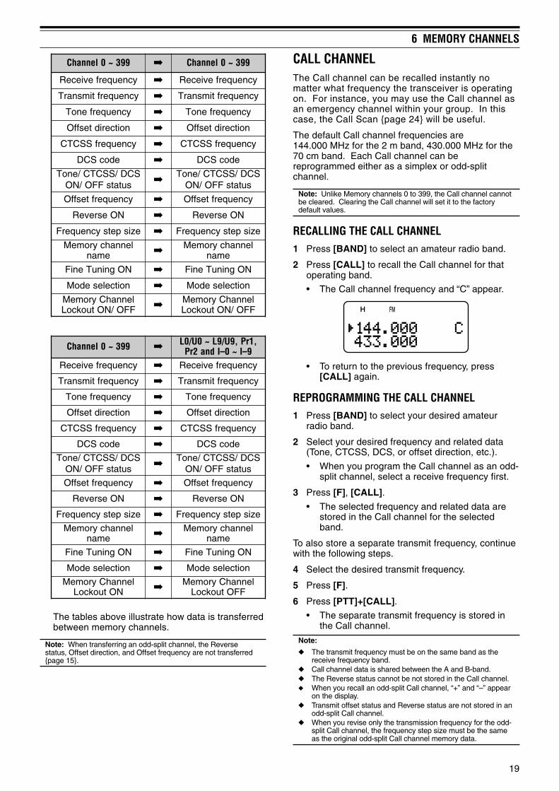
CALL CHANNELThe Call channel can be recalled instantly nomatter what frequency the transceiver is operatingon. For instance, you may use the Call channel asan emergency channel within your group. In thiscase, the Call Scan page 24 will be useful.
The default Call channel frequencies are144.000 MHz for the 2 m band, 430.000 MHz for the70 cm band. Each Call channel can bereprogrammed either as a simplex or odd-splitchannel.
Note: Unlike Memory channels 0 to 399, the Call channel cannotbe cleared. Clearing the Call channel will set it to the factorydefault values.
RECALLING THE CALL CHANNEL1 Press [BAND] to select an amateur radio band.
2 Press [CALL] to recall the Call channel for thatoperating band.
• The Call channel frequency and “C” appear.
• To return to the previous frequency, press[CALL] again.
REPROGRAMMING THE CALL CHANNEL1 Press [BAND] to select your desired amateur
radio band.
2 Select your desired frequency and related data(Tone, CTCSS, DCS, or offset direction, etc.).
• When you program the Call channel as an odd-split channel, select a receive frequency first.
3 Press [F], [CALL].
• The selected frequency and related data arestored in the Call channel for the selectedband.
To also store a separate transmit frequency, continuewith the following steps.
4 Select the desired transmit frequency.
5 Press [F].
6 Press [PTT]+[CALL].
• The separate transmit frequency is stored inthe Call channel.
Note:
The transmit frequency must be on the same band as thereceive frequency band.
Call channel data is shared between the A and B-band. The Reverse status cannot be not stored in the Call channel. When you recall an odd-split Call channel, “+” and “–” appear
on the display. Transmit offset status and Reverse status are not stored in an
odd-split Call channel. When you revise only the transmission frequency for the odd-
split Call channel, the frequency step size must be the sameas the original odd-split Call channel memory data.

20
6 MEMORY CHANNELS
INFORMATION CHANNELS10 Information channels are available for storingradio broadcasting service frequencies, such ascommunity FM broadcasting stations. For yourconveniences, pressing [INFO] instantly recalls theInformation channel to B-band.
REPROGRAMMING THE INFORMATION CHANNEL1 Press [VFO].
2 Select a desired frequency and mode.
3 Press [F].
4 Turn the Tuning control or press [ ]/ [ ] to selectthe memory channel (I–0 to I–9) in which you wantto store the data.
5 Press [MR] ([ ] or [MNU]).
• A long beep sounds and the Informationchannel data is now revised.
Note:
When you perform the Full reset page 47, all the Informationchannels recover the factory default values.
If you clear an Information Channel data page 16, thefactory default value is recovered.
You can also transfer the Information Channel data to theVFO or another memory channel.
RECALLING AN INFORMATION CHANNELPress [INFO] to recall the Information channels.
• “I–n” appears, where “n” represents theInformation channel number from “0” ~ “9”.
• If the B-band is selected for operation, you canturn the Tuning control or press [ ]/ [ ] to selectother Information channels. If the A-band isselected for operation, press [A/B] to move theoperation band to the B-band and then select adifferent Information channel.
• To exit the Information channel mode, press [A/B]to select the B-band then press [VFO] or [MR].
Note:
If you press [MN<->f], you can display the receivingfrequency in place of the memory name.
As default, no frequency data is stored in the Informationchannel. Store the frequency data before using theInformation channels. Otherwise, an error beep sounds.
CHANNEL DISPLAYWhile in this mode, the transceiver displays onlymemory channel numbers (or memory names ifstored) instead of frequencies.
1 Press [A/B]+[ ] (POWER).
• The transceiver displays the memory channelnumber in place of the operating frequencies.
2 Turn the Tuning control or press [ ]/ [ ] to selectyour desired memory channel number.
While in the Channel Display mode, only the followingkeys can be operated.
[KEY]
PMAL INOM WOL DNAB B/A OFNILQS LAB VER TNE F RMLLAC 1 TTP
lortnocgninuT1 When the “1750” is selected for the CALL key.
[F] then
PMAL 1 WOL B/A TNE F1 The light stays ON until the key is pressed again.
[KEY] (1 s)
PMAL OFNI zHM F RM
While transmitting:
PMAL UNM 1 2 3 45 6 7 8 9 0
# A B C D
When the transceiver is turned OFF, [ ] (POWER)and
B/A F
To recover normal operation, turn the transceiverOFF and press [A/B]+[ ] (POWER) again.
Note:
To enter the Channel Display mode, you must have at leastone memory channel that contains the data.
If the memory channel contains the memory name data, thememory name is displayed in place of the “CH” characters.

21
SCANScan is a useful function for hands-off monitoring ofyour favorite frequencies. By becoming comfortablewith all types of Scan, you will increase your operatingefficiency.
This transceiver provides the following types of scans.
epyTnacS esopruP
lamroNnacS
nacSdnaB ehtfodnaberitneehtsnacSdetcelesuoyycneuqerf
margorPnacS
deificepsehtsnacSniderotssegnarycneuqerf~0U/0LslennahcyromeM
9U/9L
nacSzHM nihtiwseicneuqerfehtsnacSegnarzHM1a
yromeMnacS
lennahC-llAnacS
slennahcyromeMllasnacSruoynodesab,993ot0morf
)DOHTEMRM(3.oNuneMsgnittes
nacSpuorG
yromeMdeificepsehtsnacSnodesab,spuorglennahc
RPG.M(2.oNuneMruoysgnittes)KNIL
llaCnacS
OFV dnalennahcllaCehtsnacSycneuqerfOFVtnerruceht
yromeMlennahC
dnalennahcllaCehtsnacSlennahcyromeMdetceleseht
nacSytiroirPehtnoseitivitcaehtskcehC
slennahcytiroirpdeificepssdnoces3yreve)2rP/1rP(
lennahCnoitamrofnInacS
noitamrofnIehtsnacSslennahc
lausiV*nacS
OFV
snacS ± ehtniseicneuqerf5raenezispetsdemmargorp
gnitarepotnerrucehtlangisehT.ycneuqerf
siycneuqerfhcaefohtgnertshparg-rabanideyalpsid
yromeMlennahC
slennahcyromeMehtsnacSlangisehtsyalpsiddna
anilennahchcaefohtgnertshparg-rab
* Visual Scan graphically shows the busy status of frequencies in aspecific range.
Note:
When the CTCSS or DCS function is activated, thetransceiver stops at a busy frequency and decodes theCTCSS tone or DCS code. If the tone or code matches, thetransceiver unmutes. Otherwise, it resumes scanning.
Press and hold [MONI] to pause the Scan in order to monitorthe scanning frequency. Release [MONI] to resumescanning.
Pressing and holding [PTT] causes Scan, excluding thePriority scan and Visual scan, to stop.
Pressing [MNU] causes Scan to stop except the Visual Scan. Starting Scan switches OFF the Automatic Simplex Check
(ASC) page 14. If you press any key other than the following keys during the
scan, the transceiver exits the Scan (excluding the Priorityscan and Visual scan). The Priority scan stops while “Pr1” or“Pr2” is blinking: [F], [F] (1 s), [LAMP], [MONI], [SQL],[BAL], [A/B], Tuning control, [ ]/ [ ], [F] then [SQL], and [F]then [LOW].
NORMAL SCANWhen you are operating the transceiver in VFO mode,3 types of scanning are available: Band Scan,Program Scan, and MHz Scan.
BAND SCANThe transceiver scans the entire band of thefrequency you selected. For example, if you areoperating and receiving at 144.525 MHz on theA-band, it scans all the frequencies available for the2 m band. (Refer to receiver VFO frequency rangein the specifications page 54.) When the currentVFO receive frequency is outside of the ProgramScan frequency range page 23, the transceiverscans the entire frequency range available for thecurrent VFO.
1 Press [VFO].
2 Press [BAND] to select your desired band.
3 Turn the Tuning control or press [ ]/ [ ] to selectthe frequency outside of the Program Scanfrequency range page 23.
4 Press [VFO] (1 s) to start the Band Scan.
5 To stop the Band Scan, press [VFO] or [PTT].
Note:
While scanning, you can change the scan frequency directionby turning the Tuning control or press [ ]/ [ ].
The transceiver scans the frequency range that is stored inMenu No. 4 (PROG VFO) page 39 on the A-band.
If you select a frequency within the L0/U0 ~ L9/U9 range instep 3, the Program Scan page 23 starts.
If you press [MONI], Band Scan temporarily pauses. Release[MONI] to resume scanning.
The transceiver stops scanning in all modes when it detects asignal.
If the Fine Tuning function is ON, scanning does not stop atthe busy channels.

22
7 SCAN
To perform the Program Scan, the following conditions mustbe met. Otherwise, the Band scan starts page 21.• The upper and lower limit frequencies are in the same
frequency band.• Ln < Un (where “n” is the Program Scan channel number).
MHz SCANMHz Scan allows you to scan an entire 1 MHzfrequency range within the current VFO frequency.
1 Press [VFO].
2 Turn the Tuning control or press [ ]/ [ ] to selecta frequency in which to perform the MHz Scan. Ifyou want to scan the entire 145 MHz frequency,select any frequency between 145.000 and149.995 MHz (for example, select 145.650 MHz).Scan will operate between 145.000 MHz and145.999 MHz.
3 Press [MHz] (1 s) to start the MHz Scan.
4 To stop the MHz Scan, press [MHz] or [PTT].
Note:
If the Fine Tuning function is ON, you cannot perform the MHzScan.
If you press [MONI], MHz Scan temporarily pauses. Release[MONI] to resume scanning.
PROGRAM SCANYou can limit the scanning frequency range. Thereare 10 memory channel pairs (L0/U0 ~ L9/U9)available for specifying the start and end frequencies.It monitors the range between the start and endfrequencies that you have stored in memory channelsL0/U0 to L9/U9. Before performing the ProgramScan, store the Program Scan frequency range toone of the memory channel pairs L0/U0 ~ L9/U9.
Storing Program Scan Frequency Range
1 Press [VFO].
2 Press [BAND] to select your desired band.
3 Turn the Tuning control or press [ ]/ [ ] toselect your desired start frequency.
4 Press [F], then turn the Tuning control or press[ ]/ [ ] to select a memory channel from L0 ~L9.
5 Press [MR] ([ ] or [MNU]) to store the startfrequency in the memory channel.
6 Turn the Tuning control or press [ ]/ [ ] toselect your desired end frequency.
7 Press [F], then Turn the Tuning control orpress [ ]/ [ ] to select the correspondingchannel from U0 ~ U9 (you must select thesame numeric value as in step 4).
• For example, if you selected L0 in step 4,you must select U0 in this step.
8 Press [MR] ([ ] or [MNU]) to store the endfrequency in the memory channel.
Performing the Program Scan
1 Press [VFO].
2 Turn the Tuning control or press [ ]/ [ ] toselect a frequency within the frequency rangeof memory channel L0/U0 ~ L9/U9.
3 Press [VFO] (1 s) to start the Program Scan.
4 To stop the Program Scan, press [VFO] or[PTT].
Note:
If you press [MONI], Program Scan temporarily pauses.Release [MONI] to resume scanning.
If the Fine Tuning function is ON, the scanning does not stopat the busy channels.
The transceiver stops scanning in all modes when it detects asignal.
If more than 2 Program Scan channel pairs are stored andoverlaps the frequency range among the pairs, the smallerProgram Scan memory channel number has the priority.

23
7 SCAN
MEMORY SCANMemory Scan monitors all memory channels in whichyou have stored frequencies (All-Channel Scan) oronly a desired group of memory channels (GroupScan).
ALL-CHANNEL SCANThe transceiver scans all of the memory channels inwhich you have stored frequencies.
1 Press [MR] (1 s).
• Scan starts from the last memory channelnumber and ascends up through the channelnumbers (default). Turn the Tuning control orpress [ ]/ [ ] to change the scanning direction.
• To jump to a desired channel while scanning,quickly turn the Tuning control.
2 To stop the All-Channel Scan, press [MR] or[PTT].
Note:
You must have 2 or more memory channels that contain thedata, excluding the special function memory channels.
If “CURRENT BAND” is selected for Menu No. 3 (MRMETHOD), it scans only Memory channels that have thesame frequency band data.
The transceiver stops scanning in all modes when it detects asignal.
GROUP SCANIn order to easily manage all 400 memory channels,they are divided into 8 groups page 18. For thepurpose of Group Scan, you can select a particularmemory group to be scanned, depending on thesituation. Using the Memory Group Link functionbelow, you can scan all the linked memory groups.
1 Press [MR].
2 Turn the Tuning control or press [ ]/ [ ] to selecta memory channel in the group you want to scan.For example, if you want to scan the group 0memory channels, recall memory channel 12(group 0 contains memory channels 0 ~ 49).
3 Press [MHz] (1 s).
• The memory channels within the selectedgroup are scanned.
• If the group is linked to other groups below,all the linked groups are also scanned.
4 To stop the Group Scan, press [MHz] or [PTT].
Note:
You must have 2 or more memory channels that contain thedata, excluding the special function memory channels.
The Group Scan scans all available memory channels,regardless of Menu No. 3 (MR METHOD) selection page 16.
The transceiver stops scanning in all modes when it detects asignal.
Memory Group Link
Although the 400 memory channels are dividedinto 8 groups page 18, you may sometimes wantto scan two or more groups. In this case, use theMemory Group Link function.
1 Press [MNU] to enter Menu mode.
2 Turn the Tuning control or press [ ]/ [ ] toselect Menu No. 2 (M.GRP LINK).
3 Press [ ] or [MNU].
• The memory group numbers appear.
4 Move the cursor using [ ]/ [ ], then turn theTuning control or press [ ]/ [ ] to select ordeselect the group to be linked.
• Linked groups appear at the bottom of thedisplay (in the example below, groups 0, 1,3 and 5 are linked).
5 Press [ ] or [MNU] to store the setting.Otherwise, press [ ] or [PTT] to cancel.
• You can press [MONI] to cancel the all linksat once.
• You can also press [0] ~ [7] to select ordeselect the group to be linked.

24
7 SCAN
CALL SCANA Call channel can be stored for each amateur radioband, such as the 2 m, 70 cm bands page 19. Youcan monitor one of these Call channels and thecurrent operating frequency alternatively.
1 Select the frequency (in VFO, Memory Recall, orInformation Channel mode) you want to monitor.
• In VFO mode, press [A/B] to select the A orB-band. Then, turn the Tuning control or press[ ]/ [ ] to select the desired frequency.
• In Memory Recall mode, turn the Tuningcontrol or press [ ]/ [ ] to select a memorychannel you want to monitor.
• Press [INFO] to recall the last InformationChannel you monitored.
2 Press [CALL] (1 s) to start the Call Scan.
3 The Call channel for the band and the selectedVFO frequency, memory channel or InformationChannel are monitored alternately.
4 To stop the Call Scan, press [PTT] or [CALL].
Note:
The transceiver stops scanning in all modes when it detects asignal.
You can perform the Call Scan even if the recalled memorychannel or Information channel has been locked out page26.
If the Call channel is not available for the current operatingfrequency, an error beep sounds.
PRIORITY SCANYou may sometimes want to check your favoritefrequency activities while monitoring the A andB-bands. In this case, use the Priority Scan function.It checks the activities of Pr1 and Pr2 channels every3 seconds, alternately, using the B-band receiver.If the transceiver detects a signal on Pr1 or Pr2, itrecalls the frequency to the B-band receiver.
Note: If you do not operate any control or key for 3 seconds afterthe signal drops, the transceiver returns to the original frequencyand resumes Priority Scan.
PROGRAMMING PRIORITY CHANNELS1 Press [VFO].
2 Turn the Tuning control or press [ ]/ [ ] to selectyour desired priority channel frequency.
3 Select the mode and selective call functions, ifnecessary.
4 Press [F].
• The memory channel number appears.
5 Turn the Tuning control or press [ ]/ [ ] to select“Pr1”.
6 Press [MR] ([ ] or [MNU]) to store the data on thepriority channel.
• If you want to store a second priority channel,repeat steps 1 ~ 6 and select “Pr2” in step 5.
Note: You can program any frequency available on the B-bandas a priority channel.
USING PRIORITY SCAN1 Press [F], [BAL].
• “ ” appears.
• The transceiver checks for a signal on the Pr1and Pr2 channels every 3 seconds, alternately.
• When the transceiver detects a signal on thepriority channel, “Pr1” or “Pr2” blinks and theB-band frequency changes to the prioritychannel.
• If you do not operate any control or key for3 seconds after the signal drops, thetransceiver returns to the original frequencyand resumes Priority Scan.
2 To quit Priority Scan, press [F], [BAL] again.

25
7 SCAN
Note:
The signal being received on the B-band may becomeintermittent because the Priority Scan uses the B-bandreceiver to check the priority channel(s) activities.
When a signal is received on a Priority channel with a CTCSSor DCS code programmed, the Priority channel is recalledeven if a different selective tone/ code is detected. However,the transceiver only unmutes if the signal has the sameCTCSS tone or DCS code.
If the Tone Alert function page 38 is ON for the B-band, itoverrides the Priority Scan function. This means that youcannot monitor the received signal on the Priority Channelsnor transmit on the Priority Channels.
Press and hold [MONI] to pause the Priority Scan when thetransceiver is not displaying a priority channel. Release[MONI] to resume the Priority Scan.
If you clear the Priority Channels page 16, the Priority Scanstops.
If you press any key other than the following keys while “Pr1”or “Pr2” is blinking, the transceiver exits the Priority Scan:[LAMP], [MONI], [A/B], [SQL], [BAL], [F] (1 s), and [PTT].
If you perform the Visual Scan below while Priority Scan isactivated, the Priority Scan temporarily pauses.
INFORMATION CHANNEL SCANInformation Channel Scan is similar to Group Scan.However, it scans only Information channels.
1 Press [INFO].
• The last Information channel you used isrecalled.
2 Press [INFO] (1 s) to start the InformationChannel Scan.
3 To stop the Information Channel Scan, press[INFO].
• If necessary, press [A/B] to select the B-bandand then press [VFO] or [MR] to select anotherfrequency (channel) for the B-band.
Note: The transceiver stops scanning in all modes when itdetects a signal.
VISUAL SCANWhile you are receiving, Visual Scan allows you tomonitor frequencies near the current operatingfrequency. Visual Scan graphically displays the busystatus of all frequencies in the selected range on theother band display area. You will see 6 different bar-graph levels, for each frequency (channel) point thatrepresent relative S-meter levels.
The Visual Scan monitors ±5 channels (frequencies)by centering on the current channel (frequency). Inthis way, a total of 11 channels’ (frequencies’) signalstrength status are graphically displayed.
Note:
When you perform the Visual Scan on the A-band, thetransceiver can output the audio. However, when you performthe Visual Scan on the B-band, it cannot output the audio.The S-meter does not reflect the signal strength, neither.
When the VOX function is activated, you cannot perform theVisual Scan.
When the Visual Scan is in progress, the other scan functions.
USING VISUAL SCAN (VFO)1 Select your desired band for Visual Scan.
2 Press [VFO].
3 Turn the Tuning control or press [ ]/ [ ] to selectyour desired center frequency.
• The transceiver scans the 5 upper frequenciesand 5 lower frequencies using the current VFOfrequency step page 35.
4 Press [F], [INFO] to start Visual Scan (VFO).
• The scanning frequency is displayed on thecurrent operating band and the relativeS-meter level of each frequency appears onthe other band display.
• To pause Scan, press and hold [MONI]. Whilethe Visual Scan is paused, the centerfrequency bar-graph blinks and you canmonitor the frequency. Release [MONI] toresume the Visual Scan.
5 To change the current scanning frequency, Turnthe Tuning control or press [ ]/ [ ].
• The displayed frequency changes and thecursor moves.
6 To stop the Visual Scan, press [F], [INFO].
Note:
You can press [PTT] (or [CALL] if 1750 Hz is programmed) totransmit during the scan if the center frequency is within thetransmission frequency range. The center bar-graph blinkswhile transmitting.
If the Fine Tuning function is ON, the Visual Scan cancels theFine Tuning function and automatically adjusts the frequencyto the next available frequency.

26
7 SCAN
USING VISUAL SCAN (MEMORY CHANNEL)1 Press [MR] to enter Memory Recall mode.
2 Turn the Tuning control or press [ ]/ [ ] to selectyour desired center memory channel.
3 Press [F], [INFO] to start the Visual Scan.
• The transceiver start scanning the 5 uppermemory channels and 5 lower memorychannels, by centering the selected memorychannel.
• The current scanning memory channel numberand frequency are displayed on the currentoperating band. On the other band, the relativeS-meter level of each frequency channel isdisplayed.
• To pause Scan, press and hold [MONI]. Whilethe Visual Scan is paused, the centerfrequency bar-graph blinks and you canmonitor the frequency. Release [MONI] toresume the Visual Scan.
4 To change the current scanning channel, turn theTuning control or press [ ]/ [ ].
5 To stop the Visual Scan, press [F], [INFO].
Note:
You can press [PTT] (or [CALL] if 1750 Hz is programmed) totransmit during the scan if the center frequency is within thetransmission frequency range. The center bar-graph blinkswhile transmitting.
If 11 or more memory channels are stored, “s” and “t” donot appear.
Even if the Fine Tuning ON status is stored in the memorychannels, the Visual Scan (Memory Channel) starts.
MEMORY CHANNEL LOCKOUTYou can lock out memory channels that you prefernot to monitor during Memory Scan.
1 Press [MR] to enter Memory Recall mode.
2 Turn the Tuning control or press [ ]/ [ ] to selectthe memory channel to be locked out.
3 Press [F], [MHz].
• “ ” appears at the top right of the memorychannel number, indicating the channel islocked out.
4 To unlock the memory channel, repeat steps 1 ~ 3.
• “ ” disappears.
Note:
The Program Scan memories (L0/U0 ~ L9/U9) and Prioritychannels (Pr1 and Pr2) cannot be locked out.
Even if a memory channel is locked out, you can perform theCall Scan page 24 between the Call channel and memorychannel.
If the same memory channel is recalled to the A and B-band,you cannot lock out the channel.
SCAN RESUME METHODThe transceiver stops scanning at the frequency (ormemory channel) where a signal is detected. It thencontinues or stops scanning according to whichresume mode you have selected.
• Time-Operated mode (default)
The transceiver remains on a busy frequency (ormemory channel) for approximately 5 seconds,then continues to scan, even if the signal is stillpresent.
• Carrier-Operated mode
The transceiver remains on the busy frequency (ormemory channel) until the signal drops out. Thereis a 2-second delay between signal dropout andscan resumption.
• Seek mode
The transceiver moves to a frequency or memorychannel where a signal is present and stops.
To change the scan resume method:
1 Press [MNU].
2 Turn the Tuning control or press [ ]/ [ ] to selectMenu No. 1 (SCAN RESUME).
3 Press [ ] or [MNU].
4 Turn the Tuning control or press [ ]/ [ ] to select“TIME ” (Time-Operated mode), “CARRIER”(Carrier-Operated mode), or “SEEK” (Seek mode).
5 Press [ ] or [MNU] to store the setting.Otherwise, press [ ] or [PTT] to cancel.

27
SELECTIVE CALLCTCSS and DCSYou may sometimes want to hear calls from onlyspecific persons or groups. In this case, use theselective call function. This transceiver is equippedwith CTCSS (Continuous Tone Coded SquelchSystem) and DCS (Digital Coded Squelch). Theseselective calls allow you to ignore (not hear)unwanted calls from other persons who are using thesame frequency. The transceiver unmutes only whenit receives the signal having the same CTCSS tone orDCS code.
Note:
CTCSS and DCS do not cause your conversation to beprivate or scrambled. It only relieves you from listening tounwanted conversations.
CTCSS and DCS function in only FM mode.
CTCSSA CTCSS tone is a sub-audible tone and is selectablefrom among the 42 tone frequencies listed in thetable on the following page. The list includes 37 EIAstandard tones and 5 non-standard tones. You canselect one of the tones to use as a CTCSS tone.
USING CTCSSPress [TONE] until “CT” appears.
• Each time you press [TONE], the icon cycles asfollows: “ ” (TONE) “CT” (CTCSS) “DCS”(DCS) “ ” (OFF) “ ” (TONE).
When the CTCSS function is ON, you will hear callsonly when the selected CTCSS tone is received. Toanswer the call, press and hold the PTT switch, thenspeak into the microphone.
Note:
You cannot use the CTCSS and Tone/ DCS functionssimultaneously. Switching the CTCSS function ON afterhaving activated the Tone/ DCS functions deactivates theTone/ DCS functions.
If you select a high CTCSS frequency, receiving audio ornoise that contains the same frequency portions may causeCTCSS to function incorrectly. To prevent noise from causingthis problem, select an appropriate squelch level page 6.
While transmitting the 1750 Hz tone by pressing [CALL]page 13 , the transceiver does not transmit the CTCSS tone.
SELECTING A CTCSS FREQUENCY1 While in CTCSS mode above, press [F],
[TONE].
• The current CTCSS frequency appears.
2 Turn the Tuning control or press [ ]/ [ ] to selectyour desired CTCSS frequency.
• The selectable CTCSS frequencies are thesame as those for the Tone frequency. Refer tothe table on the following page for the availableCTCSS frequencies.
3 Press [ ] or [MNU] to store the new setting.Otherwise, press [ ] or [PTT] to cancel.
CTCSS frequency:88.5 Hz
CTCSS frequency:88.5 Hz
CTCSS frequency:100.0 Hz
CTCSS/ DCS:OFF
Received
NotReceived
NotReceived

8 SELECTIVE CALL
28
CTCSS FREQ. ID SCANThis function scans through all CTCSS frequencies toidentify the incoming CTCSS frequency on thereceived signal. You may find this useful when youcannot recall the CTCSS frequency that the otherpersons in your group are using.
1 While the CTCSS function is ON, press [F],[TONE] (1 s) to start the CTCSS Freq. ID Scanfunction.
• To reverse the scan direction, turn the Tuningcontrol or press [ ]/ [ ].
• To quit the function, press [ ] or [PTT].
• When a CTCSS frequency is identified, theidentified frequency appears and blinks.
2 Press [ ] or [MNU] to program the identifiedfrequency in place of the current CTCSSfrequency. Otherwise, press [ ] if you do notwant to program the identified frequency.
• Turn the Tuning control or press [ ]/ [ ] whilethe identified frequency is blinking to resumescanning.
Available CTCSS frequencies
.oN .qerF)zH( .oN .qerF
)zH( .oN .qerF)zH( .oN .qerF
)zH(
10 0.76 21 4.79 32 3.141 43 5.602
20 3.96 31 0.001 42 2.641 53 7.012
30 9.17 41 5.301 52 4.151 63 1.812
40 4.47 51 2.701 62 7.651 73 7.522
50 0.77 61 9.011 72 2.261 83 1.922
60 7.97 71 8.411 82 9.761 93 6.332
70 5.28 81 8.811 92 8.371 04 8.142
80 4.58 91 0.321 03 9.971 14 3.052
90 5.88 02 3.721 13 2.681 24 1.452
01 5.19 12 8.131 23 8.291
11 8.49 22 5.631 33 5.302
Note:
Received signals are monitored through the speaker whilescanning is in progress.
CTCSS Freq. ID Scan does not scan the tone if a signal is notdetected.
If the CTCSS function is activated for both the A and B-band,the scan speed may be slower.
DCSDCS is similar to CTCSS. However, instead of usingan analog audio tone, it uses a continuous sub-audible digital waveform that represents a 3-digitoctal number. You can select a DCS code fromamong the 104 DCS codes listed in the table below.
USING DCSPress [TONE] until “DCS” appears.
• Each time you press [TONE], the icon cycles asfollows: “ ” (TONE) “CT” (CTCSS) “DCS”(DCS) “ ” (OFF) “ ” (TONE).
When the DCS function is ON, you will hear calls onlywhen the selected DCS code is received. To answerthe call, press and hold the PTT switch, then speakinto the microphone.
Note: You cannot use the DCS function and CTCSS/ Tonefunctions simultaneously. Switching the DCS function ON afterhaving activated the CTCSS/ Tone functions deactivate theCTCSS/ Tone functions.
SELECTING A DCS CODE1 While in DCS mode above, press [F], [TONE].
• The current DCS code appears.
2 Turn the Tuning control or press [ ]/ [ ] to selectyour desired DCS code.
• The available DCS codes are shown in thefollowing table.
320 560 231 502 552 133 314 564 216 137520 170 431 212 162 233 324 664 426 237620 270 341 322 362 343 134 305 726 437130 370 541 522 562 643 234 605 136 347230 470 251 622 662 153 544 615 236 457630 411 551 342 172 653 644 325 456340 511 651 442 472 463 254 625 266740 611 261 542 603 563 454 235 466150 221 561 642 113 173 554 645 307350 521 271 152 513 114 264 565 217450 131 471 252 523 214 464 606 327
3 Press [ ] or [MNU] to store the new setting.Otherwise, press [ ] or [PTT] to cancel.

29
8 SELECTIVE CALL
DCS CODE ID SCANThis function scans through all DCS codes to identifythe incoming DCS code on the received signal. Youmay find this useful when you cannot recall the DCScode that the other persons in your group are using.
1 While in DCS mode, press [F], [TONE] (1 s) tostart the DCS Code ID Scan function.
• To reverse the scan direction, turn the Tuningcontrol or press [ ]/ [ ].
• To quit the function, press [ ] or [PTT].
• When a DCS code is identified, the identifiedcode appears and blinks.
2 Press [ ] or [MNU] to program the identifiedfrequency in place of the current DCS code.Otherwise, press [ ] if you do not want toprogram the identified code.
• Turn the Tuning control or press [ ]/ [ ] whilethe identified DCS code is blinking to resumescanning.
Note:
Received signals are monitored through the speaker whilescanning is in progress.
DCS Code ID Scan does not scan the code if a signal is notdetected.
If the DCS function is activated for both the A and B-band, thescan speed may be slower.

DTMF FUNCTIONS
30
The keys on the keypad also function as DTMF keys;the 12 keys found on a touch-tone phone plus4 additional keys (A, B, C, D). This transceiver alsoprovides 10 dedicated DTMF memory channels. Youcan store a DTMF number (16 digits max.) with amemory name (8 digits max.) in each of the channelsto recall later for speed dialing.
MANUAL DIALINGManual Dialing requires only two steps to send DTMFtones.
1 Press and hold the PTT switch to transmit.
2 While transmitting, press the keys in sequence onthe keypad to send DTMF tones.
• The corresponding DTMF tones aretransmitted and monitored through the speaker.
• While pressing keys on the keypad, thetransceiver remains in the TX mode. You donot have to press [PTT] at the same time.
.qerF)zH( 9021 6331 7741 3361
796 1 2 3 A
077 4 5 6 B
258 7 8 9 C
149 0 # D
DTMF TX HOLDThis function causes the transceiver to remain intransmit mode for 2 seconds after you release eachkey. So, you can release the PTT switch whilesending the DTMF tones.
1 Press [MNU] to enter Menu mode.
2 Turn the Tuning control or press [ ]/ [ ] to selectMenu No. 12 (DTMF HOLD).
3 Press [ ] or [MNU].
4 Turn the Tuning control or press [ ]/ [ ] to select“ON”.
5 Press [ ] or [MNU] to store the setting.Otherwise, press [ ] or [PTT] to cancel.
AUTOMATIC DIALERIf you use the 10 dedicated memory channels to storeDTMF numbers, you need not remember a long stringof digits.
STORING A DTMF NUMBER IN MEMORY
Note: Audible DTMF tones from other transceivers near you (orfrom your own speaker) may be picked up by your microphone. Ifso, you may fail to correctly program a DTMF number.
1 Press [MNU] to enter Menu mode.
2 Turn the Tuning control or press [ ]/ [ ] to selectMenu No. 10 (DTMF STORE).
3 Press [ ] or [MNU].
4 Turn the Tuning control or press [ ]/ [ ] to selectyour desired DTMF memory channel number from0 to 9.
5 Press [ ] or [MNU].
• The display for entering a memory nameappears; the first digit blinks.
• To skip naming the channel, press [ ] or[MNU] again; jump to step 9.
6 Turn the Tuning control or press [ ]/ [ ] to selecta character. Refer to “NAMING A MEMORYCHANNEL” page 17 for the available charactersand the input method.
• You can enter alphanumeric characters plusspecial ASCII characters.
• Press [MONI] to delete the charactor at thecursor.
• You can also use the numeric keypad to entera character (special ASCII characters are notavailable). For example, each press of [2]switches entry as a, b, c, 2, A, B, C and thenback to a.
• While pressing and holding [LAMP], turn theTuning control to jump to the first character ofeach ASCII character group page 17.
7 Press [ ] to move the cursor to the next digit.
8 Repeat steps 6 and 7 to enter up to 8 digits.

31
9 DTMF FUNCTIONS• Pressing [ ] after selecting the 8th digit
completes the programming.
• To complete programming a name with lessthan 8 digits, press [MNU] or [ ] twice.
• Each press of [ ] causes the cursor to movebackward.
9 Press the keys in sequence on the keypad toenter a DTMF number with up to 16 digits.
• You can also turn the Tuning control or press[ ]/ [ ] to select the required DTMF number foreach digit. Select a space if you want to put apause.
• Press [MONI] to delete a number at the cursor.
10 Press [ ] or [MNU] to complete the programming.
You can confirm the stored DTMF number by usingsteps 1 to 4.
TRANSMITTING A STORED DTMF NUMBER1 While pressing and holding [PTT], press [MNU].
2 Release only [MNU], then turn the Tuning controlor press [ ]/ [ ] to select the desired DTMFmemory channel.
3 While still holding [PTT], press [ ] or [MNU] totransmit the DTMF tones.
• The number stored in the channel scrollsacross the display accompanied by DTMFtones from the speaker.
• After transmission, the frequency display isrestored.
If you do not need to confirm the memory channelcontents, press [0] to [9] instead of turning theTuning control or pressing [ ]/ [ ] in step 2 to selecta channel number. The stored DTMF number will beimmediately transmitted. You need not press [ ] or[MNU] in step 3.
Note: If you select an empty DTMF memory channel and press[MNU] or [ ], an error beep sounds and the frequency display isrestored.
ADJUSTING THE DTMF TONE TRANSMISSIONSPEEDThis transceiver allows you to configure the DTMFnumber transmission speed between Fast (default)and Slow. If a repeater cannot respond to the fastspeed, adjust this parameter.
1 Press [MNU] to enter Menu mode.
2 Turn the Tuning control or press [ ]/ [ ] to selectMenu No. 11 (DTMF SPD).
3 Press [ ] or [MNU].
4 Turn the Tuning control or press [ ]/ [ ] to select“FAST” (default) or “SLOW”.
• The tone duration of FAST is 50 ms and SLOWis 100 ms.
5 Press [ ] or [MNU] to store the setting.Otherwise, press [ ] or [PTT] to cancel.
ADJUSTING THE PAUSE DURATIONYou can also change the pause duration (a spacedigit) stored in memory channels; the default is500 ms.
1 Press [MNU] to enter Menu mode.
2 Turn the Tuning control or press [ ]/ [ ] to selectMenu No. 13 (DTMF PAUSE).
3 Press [ ] or [MNU].
4 Turn the Tuning control or press [ ]/ [ ] to select100/ 250/ 500 (default)/ 750/ 1000/ 1500/ 2000ms.
5 Press [ ] or [MNU] to store the setting.Otherwise, press [ ] or [PTT] to cancel.
DTMF LOCKAssuming you have a transceiver with the optionalspeaker microphone installed and you are carrying itin the holder or bag, you sometimes may want todisable the keypad DTMF transmission to avoidaccidental DTMF transmission. In this case, turn theDTMF Lock function ON.
1 Press [MNU] to enter Menu mode.
2 Turn the Tuning control or press [ ]/ [ ] to selectMenu No. 14 (DTMF LOCK).
3 Press [ ] or [MNU].
4 Turn the Tuning control or press [ ]/ [ ] to select“ON”.
5 Press [ ] or [MNU] to store the setting.Otherwise, press [ ] or [PTT] to cancel.
When this function is activated, you cannot transmitDTMF tones using the DTMF keypad (including[MNU]) during transmission.

UTILIZING THE B-BAND
32
ABOUT THE B-BANDUsually you can communicate with other amateurradio stations using A-band frequencies for receivingand transmitting. This transceiver also featuresanother receiver in addition to the A-band transceiver.The frequency for the B-band appears on the bottompart of the display. Although the A-band transceivercovers only the 2 m/ 70 cm amateur radio bands inFM mode, the B-band receiver can receive signalsfrom 100 kHz to 470 MHz in SSB, CW, FM, or AMmode, and from 470 MHz to 1.3 GHz in FM or AMmode.
In this way, you can monitor 2 different frequencies atthe same time. For example, you can listen to a localFM broadcasting station on the B-band while you aremonitoring your club channel on the A-band.
If one of the A-band amateur radio bands is selectedfor the B-band receiver in FM mode, you can alsotransmit on the B-band frequency.
B-BAND FREQUENCYSince the B-band frequency coverage is so wide, thedefault frequency band, mode, and frequency stepsize are preprogrammed as shown below.
1 Press [A/B] to select B-band.
• The “s” icon moves, indicating which band iscurrently selected for operation.
2 Press [BAND] until the desired frequency bandappears.
• Each time you press [BAND], the frequencyband cycles from the last band you selected tothe upper band frequency. When it reachesthe 23 cm band, it returns to the AM band.
• You can also press [ ]/ [ ] to select yourdesired band in VFO mode page 7.
3 Turn the Tuning control or press [ ]/ [ ] to tune toa desired frequency.
Note: You can also select one of the amateur radio bands totransmit on the B-band frequency. However, you must beoperating in FM mode to transmit.
B-band Frequency Coverage
dnaB ycneuqerF petS edoM
dnabMAzHk025~zHk001 zHk5 MA
zHM17.1~zHk025 zHk01 MA
FH
zHM5.3~zHM17.1
zH001)NOENIF(
MA
zHM0.4~zHM5.3 BSL
zHM0.7~zHM0.4 MA
zHM3.7~zHM0.7 BSL
zHM1.01~zHM3.7 MA
zHM51.01~zHM1.01 WC
zHM0.41~zHM51.01 MA
zHM53.41~zHM0.41 BSU
zHM860.81~zHM53.41 MA
zHM861.81~zHM860.81 BSU
zHM0.12~zHM861.81 MA
zHM54.12~zHM0.12 BSU
zHM98.42~zHM54.12 MA
zHM99.42~zHM98.42 BSU
zHM0.82~zHM99.42 MA
zHM7.92~zHM0.82 BSU
m6
zHM0.64~zHM7.92 zHk5 MF
zHM0.05~zHM0.64 zHk05 MFW
zHM0.25~zHM0.05 zHk01 MF
zHM0.86~zHM0.25 zHk05 MFW
zHM5.78~zHM0.86 zHk5 MF
dnabMF zHM0.801~zHM5.78 zHk05 MFW
dnabriA zHM0.731~zHM0.801 zHk52 MA
m2
zHM0.441~zHM0.731 zHk5
MFzHM0.641~zHM0.441 zHk5.21
zHM0.471~zHM0.641 zHk5
VTFHV zHM0.032~zHM0.471 zHk05 MFW
m52.1 zHM0.004~zHM0.032 zHk5.21 MF
zHM0.034~zHM0.004 zHk5.21
mc07 zHM0.044~zHM0.034 zHk52 MF
zHM0.074~zHM0.044 zHk5.21
VTFHU zHM0.268~zHM0.074 zHk05 MFW
mc32zHM0.0421~zHM0.268 zHk5.21
MFzHM0.0031~zHM0.0421 zHk52
Note: By default, the Fine Tuning function is activatedautomatically for 1.71 MHz ~ 29.7 MHz.

33
10 UTILIZING THE B-BAND
FINE TUNINGWhen you operate the B-band in LSB, USB, CW, orAM mode, you can turn the Fine Tuning function ON.You can further configure the Fine Tuning frequencystep size from 33 Hz, 100 Hz (default), 500 Hz, or1000 Hz.
ACTIVATING FINE TUNINGTo activate the Fine Tuning function:
1 Press [VFO].
2 Select a frequency (below 470 MHz) onthe B-band.
• The operating mode must be LSB, USB, CW orAM.
3 Press [FINE].
• 100 Hz digit appears.
4 Turn the Tuning control or press [ ]/ [ ] to tune toa station.
Note:
The Fine Tuning function works only when you operate thefrequency below 470 MHz.
You cannot activate the Fine Tuning function on the A-band. The Fine Tuning function does not work in FM mode (FM/
WFM/ NFM). While in Fine Tuning mode, you cannot change the frequency
step size page 35, MHz mode page 7, and MHz Scanpage 22.
When you perform the Visual Scan page 26 or directfrequency entry (excluding the same frequency band) page7, the transceiver exits Fine Tuning mode.
Simply turning the Fine Tuning function OFF will not changethe current frequency or display. However, when you changethe frequency, the transceiver will use the currently selectedfrequency step size page 35 and adjust the frequencyaccordingly, removing the transceiver from a finely tunedfrequency.
Selecting a Fine Tuning Frequency Step
You can select Fine Tuning frequency step from33 Hz, 100 Hz (default), 500 Hz, or 1000 Hz.
To select the Fine Tuning frequency step size:
1 Select a frequency on the B-band.
2 While the Fine Tuning mode is activated, press[F], [FINE].
• The current frequency step size appears.
3 Turn the Tuning control or press [ ]/ [ ] toselect your desired frequency step from 33 Hz,100 Hz (default), 500 Hz, or 1000 Hz.
4 Press [ ] or [MNU] to store the new setting.
Note: The Fine Tuning frequency step size reflects all availablefrequencies below 470 MHz for the B-band.
SELECTING A MODE FOR THE B-BANDWhen using the B-band receiver, the followingreceiving mode is available.
edoMgnivieceR segnaRycneuqerFelbaliavA
BSU/BSL zHk001 ≤ zHM074<f
WC zHk001 ≤ zHM074<f
MA zHk001 ≤ zHG3.1<f
MF zHk001 ≤ zHG3.1<f
MFW zHM7.92 ≤ zHG3.1<f
LSB/ USB/ CW/ AM/ FM/ WFMTo select the receiving mode for the B-band:
1 Press [VFO].
2 Press [A/B] to select the B-band.
3 Press [BAND], then turn the Tuning control orpress [ ]/ [ ] to select the desired frequency.
4 Press [F], [BAND] repeatedly until you select thedesired receiving mode. The mode icon cyclesfrom FM WFM AM LSB USB CW,and then goes back to FM.
Note:
“FMN” appears in place of “FM” when you select “ON” for theMenu No. 29 (FM NARROW) page 37.
Select “WFM” when you receive the audio signal of thebroadcasting stations, such as FM or TV stations.
If the Fine Tuning function is ON page 33, you cannot selectFM mode (FM/ NFM/ WFM). To select FM mode, turn theFine Tuning function OFF.
BAR ANTENNAAlthough the supplied wide-band helical antenna isused for receiving B-band frequencies, due to thesize and length limitation, it may not be suitable forlow HF band (below 10.1 MHz) reception. Thetransceiver features a built-in bar antenna for thereception frequency below 10.1 MHz. Thetransceiver automatically switches to the bar antennawhen you select a frequency below 10.1 MHz for theB-band. However, you can connect an externalantenna to the antenna connector instead.
To disable the built-in bar antenna below 10.1 MHz:
1 Press [MNU].
2 Turn the Tuning control or press [ ]/ [ ] to selectMenu No. 26 (BAR ANT).
3 Press [ ] or [MNU].
4 Turn the Tuning control or press [ ]/ [ ] to select“DISABLED”.
5 Press [ ] or [MNU] to store the setting.
Note: The bar antenna is embedded in the base of thetransceiver, horizontally. The antenna has the samecharacteristics as a dipole antenna. If the target station’s signal isweak, rotate the transceiver to find the best receiving position.

34
OPERATOR CONVENIENCESBATTERY LIFEBefore you operate the transceiver outside using abattery pack, it is important to know how long you canoperate the transceiver. The following operating timeis measured under the condition of TX: 6 seconds,RX: 6 seconds, and Stand-by: 48 seconds cycles.We recommend you carrying extra battery packs, incase the battery pack is discharged.
epyTyrettaB rewoPtuptuO/emiTgnitarepO).xorppA(sruoH
m2 mc07
L24-BP)V4.7(
H 5.6 0.6L 0.21 5.11LE 0.61 5.41
31-TB)V0.6(
H 0.5L 0.6LE 0.8
BATTERY REMAININGYou can confirm the remaining battery capacity usingthis function. Confirm the battery type below prior touse this function. To check the remaining capacity:
1 Press [F], [LOW].
• The battery remaining indicator appears.
: High battery power
: Medium battery power
: Low battery power
: Needs recharging or replace thebatteries
2 Press [ ] or [MNU] to exit the Battery remainingdisplay mode.
Note:
If you press [F], [LOW] while charging, “CHARGE” or“STANDBY” appears page 2.
When using Alkaline batteries, you may not be able totransmit at high power (“H” position) even if the batteryremaining indicator shows low battery power.
BATTERY TYPEBefore estimating the remaining battery capacity, setthe battery type in Menu No. 30 (BATTERY) to thesame type of battery that your are using (eitherLithium or alkaline).1 Press [MNU].2 Turn the Tuning control or press [ ]/ [ ] to select
Menu No. 30 (BATTERY).3 Press [ ] or [MNU].4 Turn the Tuning control or press [ ]/ [ ] to select
the battery type from “LITHIUM” and “ALKALINE”.5 Press [ ] or [MNU] to store the setting.
Otherwise, press [ ] or [PTT] to cancel.
APO (Auto Power OFF)The transceiver switches OFF automatically if nokeys or controls are pressed or adjusted, and nosignal is received for 30 minutes (default). 1 minutebefore the transceiver switches OFF, warning beepssound for a few seconds and “APO” blinks. Then, thetransceiver turns OFF automatically. You can selectthe APO time from OFF (disable), 30 (default), and60 minutes.
1 Press [MNU].
2 Turn the Tuning control or press [ ]/ [ ] to selectMenu No. 18 (APO).
3 Press [ ] or [MNU].
4 Turn the Tuning control or press [ ]/ [ ] to selectthe APO time from OFF, 30, or 60 minutes.
5 Press [ ] or [MNU] to store the setting.Otherwise, press [ ] or [PTT] to cancel.
Note:
The APO function does not work if the transceiver is scanning. When Tone Alert is ON, APO does not turn the power OFF. The APO timer starts counting down the time when no key
presses, no control adjustments, and no command (SP/MICjack) sequences are detected.
The APO warning beep sounds even if Menu No. 19 (KEYBEEP) page 35 is selected “OFF”.
ATTENUATORThe attenuator function is useful when extremelystrong signals exist nearby your receiving frequency.When these type of signals are present, the receivergain control may be erroneously controlled andoverloaded by the strong signals, rather than by thetarget receiving signal. If this happens, the targetreceiving signal can be masked and buried by thestrong signals. In this case, turn the Attenuator(approx. 20 dB) function ON. However, as a sideeffect, the target signal is also attenuated. You mayhave to adjust the VOL control to increase the audiooutput level when it is ON.
1 Press [F], [MONI].
• “ATT ON” appears for 2 seconds on the displayand the mode indicator starts blinking.
2 To turn the attenuator function OFF, press [F],[MONI] again.
• The mode indicator quits blinking.
Note:
When the attenuator function is ON, both A and B-band, areattenuated. You cannot set the attenuator functionindependently for each band.
“ATT ON” does not appear while scanning.

35
11 OPERATOR CONVENIENCES
Note: Use the PB-42L (Lithium battery pack) within thetemperature range of –10°C ~ 50°C.
BATTERY SAVERBattery Saver extends the operating time of thetransceiver. It automatically activates when thesquelch is closed and no key is pressed for morethan 10 seconds. To reduce the battery consumption,it shuts the receiver circuit OFF for the programmedtime then momentarily turn it back ON to detect asignal. To program the receiver shut-off period for thebattery saver:
1 Press [MNU].
2 Turn the Tuning control or press [ ]/ [ ] to selectMenu No. 17 (BAT SAVER).
3 Press [ ] or [MNU].
4 Turn the Tuning control or press [ ]/ [ ] to selectthe receiver shut-off period from OFF, 0.2, 0.4,0.6, 0.8, 1.0 (default), 2.0, 3.0, 4.0, and5.0 seconds.
5 Press [ ] or [MNU] to store the setting.Otherwise, press [ ] or [PTT] to cancel.
Note:
The longer the period, the more you can save the batteryconsumption. However, there is a greater chance of missinga signal.
When the DC IN jack is used, the Battery Saver function isautomatically turned OFF.
The Battery Saver function does not work while scanning. The Battery Saver function does not work in USB/ LSB/ CW.
BEAT SHIFTSince the transceiver uses a microprocessor tocontrol various functions of the transceiver, the CPUclock oscillator’s harmonics or image may appear onsome spots of the receiving frequencies. In this case,turn the Beat Shift function ON.
1 Press [MNU].
2 Turn the Tuning control or press [ ]/ [ ] to selectMenu No. 25 (BEAT SHIFT).
3 Press [ ] or [MNU].
4 Turn the Tuning control or press [ ]/ [ ] to select“ON”.
5 Press [ ] or [MNU] to store the setting.Otherwise, press [ ] or [PTT] to cancel.
BEEP FUNCTIONThe Beep function provides you confirmation of entry,error status, and malfunctions of the transceiver. Werecommend you leave it ON in order to detecterroneous operations and malfunctions.
However, to turn the beep function OFF:
1 Press [MNU].
2 Turn the Tuning control or press [ ]/ [ ] to selectMenu No. 19 (KEY BEEP).
3 Press [ ] or [MNU].
4 Turn the Tuning control or press [ ]/ [ ] to select“OFF”.
5 Press [ ] or [MNU] to store the setting.Otherwise, press [ ] or [PTT] to cancel.
The transceiver generates the following warningbeeps even if the beep function is turned OFF.
• APO warning beeps page 34• DC voltage error page 2• PLL circuit malfunctions• Time-Out timer warning beep page 38
Note: The beep output level is linked to the VOL control position.
DISPLAY CONTRASTYou can adjust the LCD contrast level from1 (weakest) to 16 (strongest) by accessing MenuNo. 16 (CONTRAST). The default level is 8.
1 Press [MNU].
2 Turn the Tuning control or press [ ]/ [ ] to selectMenu No. 16 (CONTRAST).
3 Press [ ] or [MNU].
4 Turn the Tuning control or press [ ]/ [ ] to adjustthe LCD contrast.
• The relative contrast level appears on the bar-graph.
5 Press [ ] or [MNU] to store the setting.Otherwise, press [ ] or [PTT] to cancel.
Note: If you continuously transmit or leave the transceiver sittingin a hot atmosphere, the background of the LCD display may turngrey and the contrast will become reduced. In this case, turn thetransceiver OFF or let the transceiver cool down for a while. Afterthe transceiver cools down, the LCD display returns normal.
FREQUENCY STEP SIZEChoosing the correct frequency step size is essentialin order to select your exact receive frequency usingthe Tuning control or pressing [ ]/ [ ]. You canselect your desired frequency step size from:
5 kHz, 6.25 kHz, 8.33 kHz (Air band only),9 kHz (AM band only), 10 kHz, 12.5 kHz, 15 kHz,20 kHz, 25 KHz, 30 kHz, 50 kHz, 100 kHz.
Note: 5 KHz, 6.25 kHz, and 15 kHz step size cannot be used onthe frequency above 470 MHz.
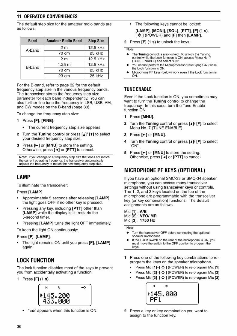
36
11 OPERATOR CONVENIENCES• The following keys cannot be locked:
[LAMP], [MONI], [SQL], [PTT], [F] (1 s),[ ] (POWER) and [F] then [LAMP].
2 Press [F] (1 s) to unlock the keys.
Note:
The Tuning control is also locked. To unlock the Tuningcontrol while the Lock function is ON, access Menu No. 7(TUNE ENABLE) and select “ON”.
You cannot perform the Microprocessor reset page 47 whilethe Lock function is ON.
Microphone PF keys below work even if the Lock function isON.
TUNE ENABLEEven if the Lock function is ON, you sometimes maywant to turn the Tuning control to change thefrequency. In this case, turn the Tune Enablefunction ON.
1 Press [MNU].
2 Turn the Tuning control or press [ ]/ [ ] to selectMenu No. 7 (TUNE ENABLE).
3 Press [ ] or [MNU].
4 Turn the Tuning control or press [ ]/ [ ] to select“ON”.
5 Press [ ] or [MNU] to store the setting.Otherwise, press [ ] or [PTT] to cancel.
MICROPHONE PF KEYS (OPTIONAL)If you have an optional SMC-33 or SMC-34 speakermicrophone, you can access many transceiversettings without using transceiver keys or controls.The 1, 2, and 3 keys located on the top of themicrophone are programmable with the transceiverkey (or key combination) functions. The defaultassignments are as follows.
Mic [1]: A/BMic [2]: VFO/ MRMic [3]: 1750 Hz
Note:
Turn the transceiver OFF before connecting the optionalspeaker microphone.
If the LOCK switch on the rear of the microphone is ON, youmust move the switch to the OFF position to program thekeys.
1 Press one of the following key combinations to re-program the keys on the speaker microphone.• Press Mic [1]+[ ] (POWER) to re-program Mic [1]• Press Mic [2]+[ ] (POWER) to re-program Mic [2]• Press Mic [3]+[ ] (POWER) to re-program Mic [3]
2 Press a key or key combination you want toassign to the function key.
The default step size for the amateur radio bands areas follows.
dnaB dnaBoidaRruetamA eziSpetS
dnab-Am2 zHk5.21mc07 zHk52
dnab-B
m2 zHk5.21m52.1 zHk5.21mc07 zHk52mc32 zHk52
For the B-band, refer to page 32 for the defaultfrequency step size in the various frequency bands.The transceiver stores the frequency step sizeparameter for each band independently. You canalso further fine tune the frequency in LSB, USB, AM,and CW modes on the B-band page 33.
To change the frequency step size:
1 Press [F], [FINE].
• The current frequency step size appears.
2 Turn the Tuning control or press [ ]/ [ ] to selectyour desired frequency step size.
3 Press [ ] or [MNU] to store the setting.Otherwise, press [ ] or [PTT] to cancel.
Note: If you change to a frequency step size that does not matchthe current operating frequency, the transceiver automaticallyadjusts the frequency to match the new frequency step size.
LAMPTo illuminate the transceiver:
Press [LAMP].
• Approximately 5 seconds after releasing [LAMP],the light goes OFF if no other key is pressed.
• Pressing any key, including [PTT] other than[LAMP] while the display is lit, restarts the5-second timer.
• Pressing [LAMP] turns the light OFF immediately.
To keep the light ON continuously:
Press [F], [LAMP].
• The light remains ON until you press [F], [LAMP]again.
LOCK FUNCTIONThe lock function disables most of the keys to preventyou from accidentally activating a function.
1 Press [F] (1 s).
• “ ” appears when this function is ON.
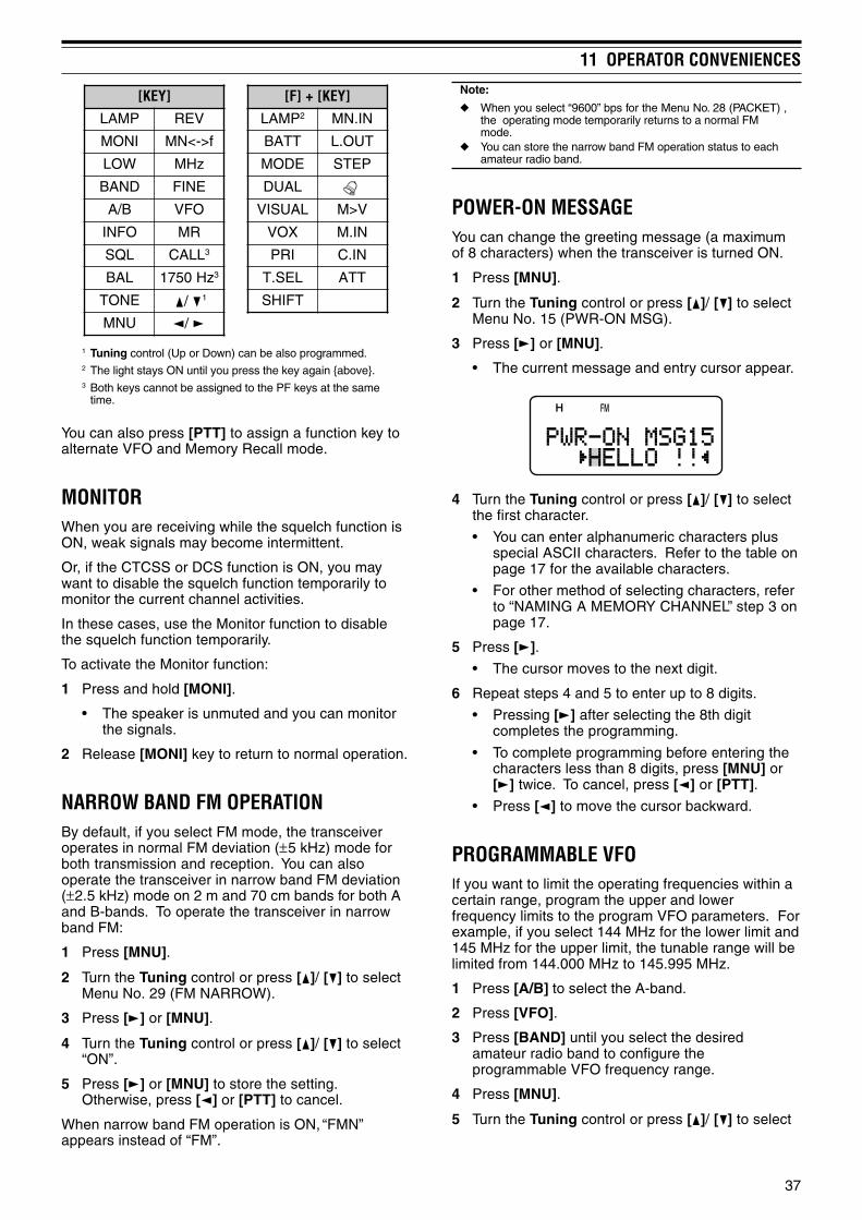
37
11 OPERATOR CONVENIENCES
]YEK[ ]YEK[+]F[PMAL VER PMAL 2 NI.NM
INOM f>-<NM TTAB TUO.L
WOL zHM EDOM PETS
DNAB ENIF LAUD
B/A OFV LAUSIV V>M
OFNI RM XOV NI.M
LQS LLAC 3 IRP NI.C
LAB zH0571 3 LES.T TTA
ENOT 1 TFIHS
UNM
1 Tuning control (Up or Down) can be also programmed.2 The light stays ON until you press the key again above.3 Both keys cannot be assigned to the PF keys at the same
time.
You can also press [PTT] to assign a function key toalternate VFO and Memory Recall mode.
MONITORWhen you are receiving while the squelch function isON, weak signals may become intermittent.
Or, if the CTCSS or DCS function is ON, you maywant to disable the squelch function temporarily tomonitor the current channel activities.
In these cases, use the Monitor function to disablethe squelch function temporarily.
To activate the Monitor function:
1 Press and hold [MONI].
• The speaker is unmuted and you can monitorthe signals.
2 Release [MONI] key to return to normal operation.
NARROW BAND FM OPERATIONBy default, if you select FM mode, the transceiveroperates in normal FM deviation (±5 kHz) mode forboth transmission and reception. You can alsooperate the transceiver in narrow band FM deviation(±2.5 kHz) mode on 2 m and 70 cm bands for both Aand B-bands. To operate the transceiver in narrowband FM:
1 Press [MNU].
2 Turn the Tuning control or press [ ]/ [ ] to selectMenu No. 29 (FM NARROW).
3 Press [ ] or [MNU].
4 Turn the Tuning control or press [ ]/ [ ] to select“ON”.
5 Press [ ] or [MNU] to store the setting.Otherwise, press [ ] or [PTT] to cancel.
When narrow band FM operation is ON, “FMN”appears instead of “FM”.
Note:
When you select “9600” bps for the Menu No. 28 (PACKET) ,the operating mode temporarily returns to a normal FMmode.
You can store the narrow band FM operation status to eachamateur radio band.
POWER-ON MESSAGEYou can change the greeting message (a maximumof 8 characters) when the transceiver is turned ON.
1 Press [MNU].
2 Turn the Tuning control or press [ ]/ [ ] to selectMenu No. 15 (PWR-ON MSG).
3 Press [ ] or [MNU].
• The current message and entry cursor appear.
4 Turn the Tuning control or press [ ]/ [ ] to selectthe first character.
• You can enter alphanumeric characters plusspecial ASCII characters. Refer to the table onpage 17 for the available characters.
• For other method of selecting characters, referto “NAMING A MEMORY CHANNEL” step 3 onpage 17.
5 Press [ ].
• The cursor moves to the next digit.
6 Repeat steps 4 and 5 to enter up to 8 digits.
• Pressing [ ] after selecting the 8th digitcompletes the programming.
• To complete programming before entering thecharacters less than 8 digits, press [MNU] or[ ] twice. To cancel, press [ ] or [PTT].
• Press [ ] to move the cursor backward.
PROGRAMMABLE VFOIf you want to limit the operating frequencies within acertain range, program the upper and lowerfrequency limits to the program VFO parameters. Forexample, if you select 144 MHz for the lower limit and145 MHz for the upper limit, the tunable range will belimited from 144.000 MHz to 145.995 MHz.
1 Press [A/B] to select the A-band.
2 Press [VFO].
3 Press [BAND] until you select the desiredamateur radio band to configure theprogrammable VFO frequency range.
4 Press [MNU].
5 Turn the Tuning control or press [ ]/ [ ] to select
/
/

38
11 OPERATOR CONVENIENCESMenu No. 4 (PROG VFO).
• The current programmable frequency range forthe band appears.
6 Press [ ] or [MNU].
7 Turn the Tuning control or press [ ]/ [ ] to selectthe lower limit frequency in MHz.
8 Press [ ] or [MNU] to store the lower limitfrequency. To cancel, press [ ] or [PTT].
• The cursor moves to the right and the upperlimit frequency blinks.
9 Turn the Tuning control or press [ ]/ [ ] to selectthe upper limit frequency in MHz.
10 Press [ ] or [MNU] to store the upper limitfrequency. To cancel, press [ ] or [PTT].
Note:
Programmable VFO is available only for A-band. You cannot program the 100 kHz or lower digits. The upper limit frequency cannot be selected lower than the
selected lower limit frequency.
SINGLE BAND OPERATIONIf you do not want to use the A and B-band receiversat the same time, you can turn the A or B-bandreceiver OFF.
1 Press [A/B] to select the band you want tooperate.
2 Press [F], [A/B].
• The frequency of the selected band appears inlarge font and the other band receiver is turnedOFF and muted.
• You can also press [A/B] to alternate the A andB-band.
3 To return to normal dual-band operation, press [F],[A/B] again.
TIME-OUT TIMERThe Time-out Timer limits the time of eachtransmission. The built-in time-out timer limits eachtransmission time to a maximum of 10 minutes. Justbefore the transceiver stops the transmission, awarning beep sounds. It is necessary to protect thetransceiver from thermal damage. You cannot turnthis function OFF.
Note: A warning beep sounds even if you select Menu No. 19(KEY BEEP) OFF.
TONE ALERTTone Alert provides an audible alarm when signalsare received on the frequency you are monitoring. Inaddition, it shows the number of hours and minuteselapsed after signals have been received. If you useTone Alert with CTCSS or DCS, it sounds only whena received CTCSS tone or DCS code matches thetone or code you selected.
1 Select your desired frequency or memory channel.
2 Press [F], [ENT].
• “ ” icon appears.
• When a signal is received, an alarm sounds for10 seconds and “ ” icon starts blinking.
• Press [PTT] while “ ” icon is blinking to turnthe Tone Alert function OFF.
• When 99 hours and 59 minutes pass after asignal has been received, counting stops.
• Each time a new signal is received, theelapsed time resets to 00:00.
Note:
While Tone Alert is ON, there is no speaker output when asignal is received. To monitor the signal, press and hold[MONI].
When Tone Alert is ON, APO does not turn the power OFF. If you switch the transceiver OFF while “ ” icon is blinking,
the transceiver does not back the elapsed time. When Tone Alert is ON, you can use only the following
functions: [LAMP], [MONI], [SQL], [A/B], [F] then [LAMP],and [F] then [ENT].
TX INHIBITYou can inhibit the transmission to preventunauthorized individuals from transmitting, or toeliminate accidental transmissions while carrying thetransceiver.
1 Press [MNU].
2 Turn the Tuning control or press [ ]/ [ ] to selectMenu No. 8 (TX INHIBIT).
3 Press [ ] or [MNU].
4 Turn the Tuning control or press [ ]/ [ ] to select“ON”.
5 Press [ ] or [MNU] to store the setting.Otherwise, press [ ] or [PTT] to cancel.
• “TX INHIBIT!” appears and an error beepsounds if you press [PTT] while TX Inhibit isactivated.

39
11 OPERATOR CONVENIENCES
Note:
If TNC is selected for Menu No. 9 (SP/MIC JACK), thesquelch status (REM/ SQ) changes based on your volumebalance settings pages 42, 43.
You can also set the volume balance while in Single BandOperation page 38.
VOX (VOICE-OPERATED TRANSMIT)VOX eliminates the necessity of manually switchingto the transmit mode each time you want to transmit.The transceiver automatically switches to transmitmode when the VOX circuitry senses that you havebegun speaking into the microphone.
When you operate the VOX function, you must usean optional accessory, HMC-3 or KHS-21. Becauseboth the internal speaker and microphone are toonear to be used for the VOX function.
To turn the VOX function ON:
Press [F], [SQL].
• “VOX” appears.
• To exit VOX mode, press [F], [SQL] again.
Note:
You cannot turn the VOX function ON while the Visual Scanpages 25 is activated.
While the VOX function is ON, the Menu No. 28 (PACKET)settings return to 1200 bps page 42.
While the VOX function is ON, you cannot use [ ]/ [ ]/ [ ]/[ ] to adjust other settings, such as the frequency andoperating band.
While in the Menu mode page 9, the VOX function isdisabled temporarily.
Since the VOX circuit must detect the presence of your voice,you may notice a slight delay in transmission. The very firstpart of your message may not be transmitted.
Turn the HMC-3’s VOX function OFF when you use theinternal VOX function.
VOX GAINTo enjoy the VOX function, take the time to properlyadjust the VOX Gain. This level controls the VOXcircuit to detect the presence or absence of yourvoice. There are 2 ways of adjusting the VOX Gain.
When the VOX function is already ON:
1 Press [ ]/ [ ] to select the desired VOX Gain from0 (least sensitive) to 9 (most sensitive).
• The VOX Gain level numbers, “G: 4” changesaccordingly (default is 4).
TX POWERTo change the transmission output power:
Press [LOW].
• Each time you press [LOW], the icon cycles fromH L EL, and then goes back to H.
The output power varies depending on the batterytype and operating voltage. The table below showsthe approximate output power when the transceiveroperates with different types of battery or DC powersource.
yrettaBepyT
rewoPtuptuOnoitceleS ).xorppA(rewoPtuptuO
31-TB)V0.6(
H W5.0L W3.0LE W50.0
L24-BP)V4.7(
H W0.5L W5.0LE W50.0
NICD)V8.31(
H W0.5L W0.2LE W5.0
Note:
You can store the TX Power settings independently for A andB-band.
If the DC IN voltage exceeds 14.5 V DC and “H” (High Power)is selected, “H” icon blinks and the output power is reduced to“L” level (Low Power) automatically.
When you operate the transceiver on the 70 cm band usingthe DC IN jack at the “H” position (high power), the internalthermal protector activates in about 2 ~ 5 minutes, dependingon the ambient temperature. If you still want to continue orrepeat the transmission, use the “L” (low power) positioninstead page 51.
VOLUME BALANCEWhile you are receiving on the A and B-bands at thesame time, you may sometimes feel that the audiooutput on either band is too loud. You can adjust thevolume balance level of the bands.1 Press [BAL].
• The balance scale and blinking cursor appear.
2 Turn the Tuning control or press [ ]/ [ ] tochange the volume balance level of the bands.
A-band Max Max Max Att MuteB-band Mute Att Max Max Max
Max: Maximum, Mute: Muted, Att: Attenuated
3 Press [ ] or [MNU] to store the setting.Otherwise, press [ ] to cancel without changingthe current settings.

40
11 OPERATOR CONVENIENCES2 While speaking into the microphone using your
normal tone of voice, adjust the VOX Gain bypressing [ ]/ [ ] until the transceiver reliablyswitches to transmit mode each time you speak.
• The setting should not allow background noiseto switch the transceiver to transmit mode.
From the Menu:
1 Press [MNU].
2 Turn the Tuning control or press [ ]/ [ ] to selectMenu No. 21 (VOX GAIN).
3 Press [ ] or [MNU].
4 Turn the Tuning control or press [ ]/ [ ] to selectthe desired VOX Gain (default is 4).
• The selectable gain range is from 0 (leastsensitive) to 9 (most sensitive).
• The setting should not allow background noiseto switch the transceiver to transmit mode.
5 Press [ ] or [MNU] to store the setting.Otherwise, press [ ] or [PTT] to cancel.
VOX DELAY TIMEIf the transceiver returns to receive mode too quicklyafter you stop speaking, your final word may not betransmitted. To avoid this, select an appropriatedelay time that allows all of your words to betransmitted. However, do not make the delay overlylong. There are 2 ways of adjusting the VOX DelayTime.
When the VOX function is already ON:
Press [ ]/ [ ] to select the desired delay time from250, 500 (default), 750, 1000, 1500, 2000 and3000 ms.
• The VOX Delay Time, “D: 500ms” changesaccordingly.
From the Menu:
1 Press [MNU].
2 Turn the Tuning control or press [ ]/ [ ] to selectMenu No. 22 (VOX DELAY).
3 Press [ ] or [MNU].
4 Turn the Tuning control or press [ ]/ [ ] to selectthe desired delay time from 250, 500 (default),750, 1000, 1500, 2000 and 3000 ms.
5 Press [ ] or [MNU] to store the setting.Otherwise, press [ ] or [PTT] to cancel.
Note:
If you press [PTT] while the VOX function is ON, the VOXDelay Time is not reflected to the transmission.
If you press [CALL] (if 1750 Hz is programmed) page 13 totransmit 1750 Hz tone, the VOX Delay Time is not reflected.
If the DCS function page 28 is ON, the transceiver remainsin the transmission mode for the VOX Delay Time, then itsends “Turn-Off Code” to close the receiving parties squelch.
VOX ON BUSYYou can configure the transceiver to force VOXtransmission even if the transceiver is receiving asignal on A or B-band.
1 Press [MNU].
2 Turn the Tuning control or press [ ]/ [ ] to selectMenu No. 20 (VOXonBUSY).
3 Press [ ] or [MNU].
4 Turn the Tuning control or press [ ]/ [ ] to select“ON”.
• To suppress the VOX transmission when thetransceiver is receiving a signal, select “OFF”.
5 Press [ ] or [MNU] to store the setting.Otherwise, press [ ] or [PTT] to cancel.
Note: You can press [PTT] or [CALL] (if 1750 Hz isprogrammed) to transmit, regardless of Menu No. 20 (VOXonBUSY) settings.

41
OPTIONAL ACCESSORIES
PG-2WDC Power Cable
PG-3JCigarette Lighter PowerCable
KHS-21Headset
PB-42LLi-ion Battery Pack(7.4 V, 1550 mAh)
HMC-3Headset (with VOX/ PTT)
EMC-3Clip Microphone withEarphone
SMC-33Speaker Microphone (withPF keys)
SMC-32Speaker Microphone
BT-13Battery Case (4 AA/ LR6)
SMC-34Speaker Microphone (withPF keys and VOL control)

INTERFACING TO PERIPHERALS
42
SP/MIC JACKThe SP/MIC jack on the transceiver can beconfigured to interface to various kind of theperipherals available for the transceiver, such as aspeaker microphone (SMC-32/ 33/ 34), PC interfacecable and a TNC. Access Menu No. 9 (SP/MICJACK) and select the peripheral type from “SP/MIC”,“TNC”, and “PC”.
You can further configure the transceiver to interfaceto a high speed (9600 bps) TNC that requires a directFM modulation below.
SELECTING SP/MIC JACK FUNCTIONUnless you connect the transceiver to a TNC or PC,the default setting of the SP/MIC jack function (MenuNo. 9), “SP/MIC” works fine. However, if you want tointerface to a different type of peripheral, configurethe SP/MIC jack function:
1 Press [MNU] to enter Menu mode.
2 Turn the Tuning control or press [ ]/ [ ] to selectMenu No. 9 (SP/MIC JACK).
3 Press [ ] or [MNU].
4 Turn the Tuning control or press [ ]/ [ ] to selectthe appropriate peripheral type from “SP/MIC”(default), “TNC”, and “PC”.
CIM/PSnoitcnuF epyTlarehpireP
CIM/PS,tesdaeh,enohorcimrekaepS
hcleuqsatuohtiwCNT,enohpraetroppussutats
CNT troppussutatshcleuqsahtiwCNT
CPlortnoclennahcyromemehthtiwCP
reviecsnartehtroferawtfos
5 Press [ ] or [MNU] to store the setting.Otherwise, press [ ] or [PTT] to cancel.
• If necessary, configure and select theadditional settings.
6 Press [ ] (POWER) to turn the transceiver OFF.
7 Connect a peripheral to the SP/MIC jack.
8 Press [ ] (POWER) to turn the transceiver ON.
SP/MIC
If you plug the speaker microphone or headsetinto the SP/MIC jack, access Menu No. 9 andselect “SP/MIC” (default). To emulate theprogrammable function keys using external keys inorder to control the transceiver, refer to the circuitdiagram below.
3.5 V 10 µF
PT
T
LOC
K S
W
SW
-1
3.9k
SW
-2
10k
SW
-3
27k
TH-F7A
SP
MIC
Note 1:Voltage is developed across a 100W resistor on the 3.5 V line inthe transceiver. When 2 mA flows, approximately 3.3 V isdeveloped.
Note 2:A 10 mF capacitor is not required in the following cases.• When other equipment has DC blocking capacitors.• When a 2-terminal electret condenser microphone is used.
TNC
If you want to utilize the squelch status on yourTNC, access Menu No. 9 and select “TNC”. Fromthe TNC, make the interface cable that connects toSP/PRD, MIC/PKD, PTT, REM/SQ, and GND onthe transceiver SP/MIC jack terminal. In addition,if your TNC supports 9600 bps packet (G3RUH/GMSK 9600 bps modem), access Menu No. 28(PACKET) and select “9600” bps. This optionallows you to transmit/ receive packet signals in adirect FM modulation/ quadrature detector output.You must use the A-band to transmit and receive9600 bps packet signal.The following diagram shows the availableterminals on the SP/MIC jack for the TNC.
To TNC RX audio input
To TNC DCD input
GND
NC
To TNC TX audio output
PTT
Demodulator output
Modulation input
Speaker output
Remote input
Squelch output
Microphone input
PTT input
3.5 V DC
High speed(9600 bps)
High speed(9600 bps)
Normal(1200 bps)
Normal(1200 bps)
SP/PRD
REM/SQ
GND
3.5 V
MIC/PKD
PTT
Note: When you select 9600 bps for Menu No. 28 (PACKET), you
cannot monitor the sound from the speaker. Select 1200 bpsfor Menu No. 28 (PACKET) when you return to normaloperation.
While the VOX function is turned ON, Menu No. 28 (PACKET)returns to 1200 bps page 39.
2.5 mmPlug
3.5 mmPlug
Speaker
Microphone
3.5 mmPlug
2.5 mmPlug
Note 1 Note 2

43
13 INTERFACING TO PERIPHERALSSince the transceiver can receive 2 different
frequencies, it outputs the squelch status(REM/SQ) as shown the table below.
Press [BAL] to set the Volume balance page 39.
LOVecnalaB dnaBgnisneSQS/MER
dnab-A
dnab-Bro/dnadnab-A)muscigol(
dnab-B
PC
If you want to connect the transceiver to a PC inorder to manage the memory channels in thetransceiver, you need an interface cable. You willalso need the supported software to download,upload, and edit the memory channel contents ofthe transceiver.
To manage the memory contents in the transceiverfrom a PC, access Menu No. 9 and select “PC”.
For your information, the following diagram showshow the TH-F7A communicates to the PC using aserial (COM) port.
RXDDTRDSRGND
RTSCTSTXD
SP
MIC
Note: Contact an authorized dealer for the PC Interface cableavailability.
2.5 mmPlug
3.5 mmPlug
Levelconverter COM port
TH-F7A
PC with a serial (COM) port
TH-F7A
PC Interface cable

TROUBLESHOOTING
44
DO NOT PACK THE EQUIPMENT IN CRUSHEDNEWSPAPERS FOR SHIPMENT! EXTENSIVE DAMAGEMAY RESULT DURING ROUGH HANDLING OR SHIPPING.
Note:
Record the date of purchase, serial number and dealer fromwhom the transceiver was purchased.
For your own information, retain a written record of anymaintenance performed on the transceiver.
When claiming warranty service, please include a photocopyof the bill of sale, or other proof-of-purchase showing the dateof sale.
CLEANINGThe keys, controls, and case of the transceiver arelikely to become soiled after extended use. Removethe controls from the transceiver and clean them witha neutral detergent and warm water. Use a neutraldetergent (no strong chemicals) and a damp cloth toclean the case.
BACKUP BATTERYThis transceiver uses an EEPROM to store memorychannel data, menu configurations, and all necessaryoperation parameters. So, you never have to worryabout replacing back-up batteries to operate thetransceiver.
GENERAL INFORMATIONYour transceiver has been factory aligned and testedto specification before shipment. Under normalcircumstances, the transceiver will operate inaccordance with these operating instructions. Alladjustable trimmers, coils and resistors in thetransceiver were preset at the factory. They shouldonly be readjusted by a qualified technician who isfamiliar with this transceiver and has the necessarytest equipment. Attempting service or alignmentwithout factory authorization can void the transceiverwarranty.
When operated properly, the transceiver will provideyears of service and enjoyment without requiringfurther realignment. The information in this sectiongives some general service procedures requiring littleor no test equipment.
SERVICEIf it is ever necessary to return the equipment to yourdealer or service center for repair, pack thetransceiver in its original box and packing material.Include a full description of the problemsexperienced. Include your telephone number, faxnumber, and email address (if available) along withyour name and address in case the servicetechnician needs to contact you for furtherexplanation while investigating your problem. Do notreturn accessory items unless you feel they aredirectly related to the service problem.
You may return your transceiver for service to theauthorized KENWOOD dealer from whom youpurchased it or any authorized KENWOOD servicecenter. A copy of the service report will be returnedwith the transceiver. Please do not sendsubassemblies or printed circuit boards. Send thecomplete transceiver.
Tag all returned items with your name and call signfor identification. Please mention the model andserial number of the transceiver in anycommunication regarding the problem.
SERVICE NOTEIf you desire to correspond on a technical oroperational problem, please make your note short,complete, and to the point. Help us help you byproviding the following:
1 Model and serial number of equipment.
2 Question or problem you are having.
3 Other equipment in your station pertaining to theproblem.
4 Meter readings.
5 Other related information (menu setup, mode,frequency, key sequence to induce malfunction,etc).
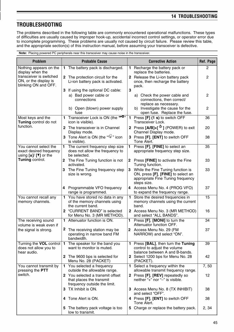
45
14 TROUBLESHOOTING
TROUBLESHOOTINGThe problems described in the following table are commonly encountered operational malfunctions. These typesof difficulties are usually caused by improper hook-up, accidental incorrect control settings, or operator error dueto incomplete programming. These problems are usually not caused by circuit failure. Please review this table,and the appropriate section(s) of this instruction manual, before assuming your transceiver is defective.
Note: Placing powered PC peripherals near this transceiver may cause noise in the transceiver.
melborP esuaCelbaborP noitcAevitcerroC egaP.feR
ehtnosraeppagnihtoNehtnehwyalpsid
dehctiwssireviecsnartsiyalpsidehtro,NO
.FFOdnaNOgniknilb
1 .degrahcsidsikcapyrettabehT 1 rokcapyrettabehtegrahceR.seirettabehtecalper
2
2
3
ehtroftiucricnoitcetorpehT.detavitcasikcapyrettabnoi-iL
:elbacCDlanoitpoehtgnisufI
2
3
kcapyrettabnoi-iLehtesaeleRyrettabehtegrahcerneht,ecno
.kcap
2
)a
)b
roelbacrewopdaBsnoitcennoc
ylppusrewop)nwolb(nepOesuf
)a
)b
dnaelbacrewopehtkcehC/tcerrocneht,snoitcennoc
.yrassecensaecalperehtrofesuacehtetagitsevnI
.esufehtecalpeR.esufnepo
2
2
ehtdnasyektsoMgninuT tonodlortnoc
.noitcnuf
1 ”“eht(NOsikcoLreviecsnarT.)elbisivsinoci
1 sserP )s1(]F[ FFOhctiwsot.kcoLreviecsnarT
63
2 lennahCnisireviecsnartehT.edomyalpsiD
2 sserP ][+]B/A[ tixeot)REWOP(.edomyalpsiDlennahC
02
3 noci”“eht(NOsitrelAenoT.)elbisivsi
3 sserP ]F[ , ]TNE[ FFOhctiwsot.trelAenoT
83
ehttcelestonnacuoYycneuqerfderisedtcaxe
gnisu ][ / ][ ehtrogninuT .lortnoc
1 ezispetsycneuqerftnerrucehTotycneuqerfehtwollatonseod
.detceleseb
1 sserP ]F[ , ]ENIF[ natcelesot.ezispetsycneuqerfetairporppa
53
2 tonsinoitcnufgninuTeniFehT.detavitca
2 sserP ]ENIF[ eniFehtetavitcaot.noitcnufgninuT
33
3 petsycneuqerfgninuTeniFehT.gnorwsiezis
3 sinoitcnufgninuTeniFehtelihWsserp,NO ]F[ , ]ENIF[ natcelesot
ycneuqerfgninuTeniFetairporppa.ezisspets
33
4 ycneuqerfOFVelbammargorP.demmargorpsiegnar
4 )OFVGORP(4.oNuneMsseccA.egnarycneuqerfehtdnapxeot
73
ynallacertonnacuoY.slennahcyromem
1 ynaniatadonderotsevahuoYgnisuslennahcyromemehtfo
.dnabtnerruceht
1 niseicneuqerfderisedehterotStnerrucehtgnisuslennahcyromem
.dnab
51
2 detcelessi”DNABTNERRUC“.)DOHTEMRM(3.oNuneMrof
2 )DOHTEMRM(3.oNuneMsseccA.”SDNABLLA“tcelesdna
61
dnuosgniviecerehTfinevekaewsiemulov
.gnortssilangiseht
1
2
.NOsinoitcnufrotaunettA 1 sserP ]F[ , ]INOM[ ehtnrutot.FFOnoitcnufrotaunettA
43
ebyamnoitatsgniviecerehTMFdnabworrannignitarepo
.htdiwdnab
2 MF(92.oNuneMsseccA.”NO“tcelesdna)WORRAN
73
ehtgninruT LOV lortnocotuoywollatonseod
.oiduaraeh
1
2
uoydnabehtrofrekaepsehT.detumsirotinomottnaw
rofdetcelessispb0069ehT)TEKCAP(82.oNuneM
1
2
sserP ]LAB[ ehtnrutneht, gninuTemulovehttsujdaotlortnoc
.sdnab-BdnaAneewtebecnalab82.oNuneMrofspb0021tceleS
.)TEKCAP(
93
24
ybtimsnarttonnacuoYehtgnisserp TTP
.hctiws
1 ycneuqerfadetcelesuoY.egnarelbawollaehtedistuo
1 ehtnihtiwycneuqerfatceleS.egnarycneuqerftimsnartelbawolla
05,7
2 tesffotimsnartadetcelesuoYtimsnartehtsecalptaht
.timilehtedistuoycneuqerf
2 sserP ]F[ , ]VER[ osyldetaeper.elbisivsi”–“ron”+“rehtien
21
3 .NOsitibihnIXT 3 )TIBIHNIXT(8.oNuneMsseccA.”FFO“tcelesdna
83
4 .NOsitrelAenoT 4 sserP ]F[ , ]TNE[ FFOhctiwsot.trelAenoT
83
5 ootsiegatlovkcapyrettabehT.timsnartotwol
5 .kcapyrettabehtecalperroegrahC 43,2

46
14 TROUBLESHOOTING
melborP esuaCelbaborP noitcAevitcerroC egaP.feR
ebtonnacretaepeR.dessecca
1 .detcelessiycneuqerfenotgnorW 1 sserP ]F[ , ]ENOT[ atcelesot.enotsseccaretaeperreporp
31
2 ycneuqerftesfforetaepergnorW.detcelessi
2 )TESFFO(6.oNuneMsseccAtfihsetairporppanatcelesdna
.ycneuqerf
21
3 .detcelessinoitceridtfihsgnorW 3 .snoitceridtfihsrehtoyrT 21
ebtonnacenotFMTD.dettimsnart
.NOsikcoLFMTD )KCOLFMTD(41.oNuneMsseccA.”FFO“tcelesdna
03
tonseodretaepeRFMTDruoytpecca
.senot
.trohsootsinoitarudenotFMTD )DPSFMTD(11.oNuneMsseccA.”WOLS“tcelesdna
03
stimsartreviecsnarTehtgnisserptuohtiw
.hctiwsTTP
.NOsinoitcnufXOV sserP ]F[ , ]LQS[ XOVehtnrutot.FFOnoitcnuf
93
reviecsnartehTonrofFFOsehctiws
.nosaertnerappa
)OPA(ffOrewoPcitamotuAehT.demmargorpsinoitcnuf
dna)OPA(81.oNuneMsseccA.FFOnoitcnufOPAehtnrut
43
sirewoptuptuoehT”H“ehtdnadecuder
.sknilbnoci
s’reviecsnartehtfoerutarepmetehTtimsnartothgihootsemocebsissahc
lanretniehT.rewoptuptuohgihtaderewolstiucricnoitcetorplamreht
.levelrewoptuptuoeht
ehttelroFFOreviecsnartehtnruTeviecerehtninwodloocreviecsnart
.elihwarofedom
84
snruterreviecsnartehTaretfaedomeviecerot
.noissimsnartgnol
dedeecxeemitnoissimsnartehT.setunim01
ehtslecnacremittuo-emitni-tliubehTylsuounitnocuoyfinoissimsnart
uoY.setunim01revoroftimsnartsitI.FFOnoitcnufsihtnruttonnac
reviecsnartehttcetorpotyrassecen.egamadlamrehtehtmorf
83
seodnoitcnufnacsehTehtemuserton
ehtretfagninnacsastcetedreviecsnart
.langis
uneMrof”KEES“detcelesevahuoY.)EMUSERNACS(1.oN
”REIRRAC“ro”EMIT“rehtietceleS.)EMUSERNACS(1.oNuneMrof
62

47
14 TROUBLESHOOTING
MICROPROCESSOR RESETIf your transceiver seems to be malfunctioning,resetting the microprocessor may solve the problem.The following 3 reset modes are available. Whenperforming the reset, you may lose memory data andstored information. Back up or write down importantdata before performing the reset.
INITIAL SETTINGSFor each VFO, the factory defaults for the operatingfrequency and mode are as follows.
• A-band: 144.000 MHz/ FM• B-band: 430.000 MHz/ FM
The Memory channels have no data stored. Refer topages 19 and 20 for the Call Channels andInformation Channels default values.
VFO RESETThis resets the transceiver parameters excluding theMenu contents and Memory channel contents.
Note: Menu No. 4 (PROG VFO) and No. 6 (OFFSET) return tothe factory default values.
MENU RESETThis resets the parameters only in the Menu items tofactory default values.
FULL RESETThis resets all transceiver parameters to the factorydefault values.
PERFORMING RESETThere are 2 ways to enter the reset mode selection.However, the transceiver must be configured to theLock function OFF page 38.
When the transceiver is turned OFF:
1 Press [F]+[ ] (POWER).
• All indicators are lit.
2 Release [F].
• Proceed to step 3 below.
From the Menu:
1 Press [MNU].
2 Turn the Tuning control or press [ ]/ [ ] to selectMenu No. 31 (RESET?). Press [ ] or [MNU].
3 Select the reset mode by turning the Tuningcontrol or press [ ]/ [ ]. If you select “NO”, thetransceiver exits the reset mode.
4 Press [ ] or [MNU] to proceed.
• If you press any keys, other than [LAMP] and[MONI], the transceiver exits the reset mode.
• A reset confirmation message appears.
5 Press [ ] or [MNU] to reset the transceiver.
• If you press any keys, other than [LAMP] and[MONI], the transceiver exits the reset mode.

48
14 TROUBLESHOOTING
OPERATION NOTICESThe transceiver has been designed and engineeredto avoid possible hardware glitches. However, youmay notice the following symptoms when you operatethe transceiver. These symptoms are notmalfunctions.
OPERATING VOLTAGEAs stated in “SPECIFICATIONS” page 53, thistransceiver operates on a DC voltage from 5.5 V ~7.5 V DC (battery terminal) or 12.0 V ~ 16.0 V DC(DC IN jack). If you find that the transceiver cannotbe switched ON, or “VOLTAGE ERROR” appears, thesupplied power source may be outside of thespecified range.
In such a case, remove the DC power cable from thetransceiver immediately and confirm that the suppliedvoltage is within the specified range.
If you are using a variable DC power supply tooperate the transceiver, adjust the DC power supplyvoltage to 12.0 V DC. Considering the output powerefficiency and thermal characteristics of thetransceiver, this is the optimal voltage to operate thetransceiver.
TUNING IN SSB/ CW MODEThe transceiver uses a general purpose IF filter toreceive signals in LSB, USB, CW and AM modes.So, when you receive signals in LSB or USB mode,the opposite side band signal is not fully attenuated.At the same time, since the same filter is used for CWreception, you may have difficulties seperating theCW signal from other signals in the crowded band.
To best tune in to a SSB signal, follow the instructionbelow.
When you receive signals in USB mode:
1 Turn the Fine Tuning function ON page 33.
2 Tune to the target signal while starting at a lowerfrequency, using the Tuning control.
When you receive signals in LSB mode:
1 Turn the Fine Tuning function ON page 33.
2 Tune to the target signal while starting at a higherfrequency, using the Tuning control.
RECEIVING IN AM BANDIf you receive a weak signal in AM band, you maynotice a high pitched squealing noise in thebackground. This noise is generated by the internalDC/DC converter and it cannot be removed.
RECEIVING SIGNALS IN CITIESWhen you receive signals in cities, the receiver’s entireS-meter may light up without receiving any strongsignals. This happens when the RF amplifier in thereceiver is overloaded by strong interference signalsthat are nearby. In this case, turn the Attenuatorfunction ON page 34 to reduce the interferencesignal level. You may further have to adjust thevolume level while receiving the target signal.
BEAT AND NOISEWhen you have the same 2 m and 70 cm bandfrequencies for both A and B-band receivers, theVisual Scan may indicate the signals on the bar-graph display even if no signal is monitored on theA-band receiver. This error occurs due to theinternal spurious harmonics that are generated bythe B-band-receiver. Refer to “INTERNAL BEATS”below for the frequencies.
You may also hear some noise in the receiving signalin the following cases.
• You perform any scan on the other receiver.
• You perform the Visual Scan on the B-bandreceiver.
TRANSMISSIONIf you continuously transmit for more than 3 minutesat high power (5 W), the transceiver becomes warm.If you continue or repeat the transmission before thetransceiver cools down, the thermal protectorautomatically decreases the output power to 0.5 W.“H” also blinks at the same time. If this happens, letthe transceiver cool down for a while beforetransmitting again.
If you continuously transmit for an extended period athigh power (5 W) using the DC IN jack, thetransceiver becomes warm. If you continue or repeatthe transmission before the transceiver cools down,the thermal protector automatically decreases theoutput power to 0.5 W. “H” will blink at this time. Forthe 70 cm band, the thermal protector activates inabout 2 ~ 5 minutes at high power, depending on theambient temperature. In these cases, let thetransceiver cool down for a while or use the “L” (lowpower) position before transmitting again.
SUPPLIED ANTENNAThe supplied antenna is designed to give you thebest transmission and reception performance on the2 m and 70 cm amateur radio bands. So, it may notbe suitable for the frequency that you want to receive.Use an appropriate antenna for the frequency if thesensitivity is low.
INTERNAL BEATSIf one of the formulas on the next page is true, theS-meter moves without receiving any signals or youcannot receive any signals. This is inevitable whenyou use superheterodyne receivers.
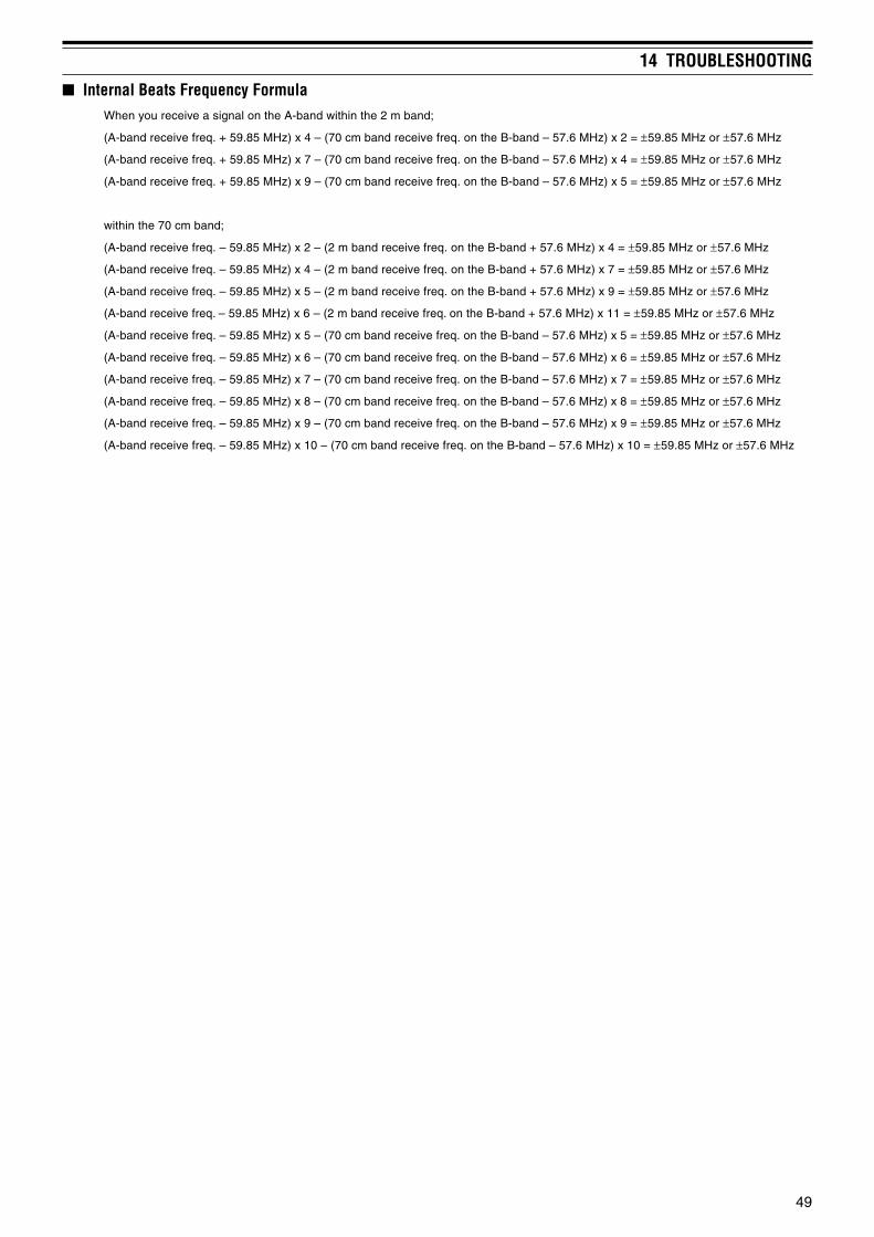
49
14 TROUBLESHOOTING
Internal Beats Frequency FormulaWhen you receive a signal on the A-band within the 2 m band;
(A-band receive freq. + 59.85 MHz) x 4 – (70 cm band receive freq. on the B-band – 57.6 MHz) x 2 = ±59.85 MHz or ±57.6 MHz
(A-band receive freq. + 59.85 MHz) x 7 – (70 cm band receive freq. on the B-band – 57.6 MHz) x 4 = ±59.85 MHz or ±57.6 MHz
(A-band receive freq. + 59.85 MHz) x 9 – (70 cm band receive freq. on the B-band – 57.6 MHz) x 5 = ±59.85 MHz or ±57.6 MHz
within the 70 cm band;
(A-band receive freq. – 59.85 MHz) x 2 – (2 m band receive freq. on the B-band + 57.6 MHz) x 4 = ±59.85 MHz or ±57.6 MHz
(A-band receive freq. – 59.85 MHz) x 4 – (2 m band receive freq. on the B-band + 57.6 MHz) x 7 = ±59.85 MHz or ±57.6 MHz
(A-band receive freq. – 59.85 MHz) x 5 – (2 m band receive freq. on the B-band + 57.6 MHz) x 9 = ±59.85 MHz or ±57.6 MHz
(A-band receive freq. – 59.85 MHz) x 6 – (2 m band receive freq. on the B-band + 57.6 MHz) x 11 = ±59.85 MHz or ±57.6 MHz
(A-band receive freq. – 59.85 MHz) x 5 – (70 cm band receive freq. on the B-band – 57.6 MHz) x 5 = ±59.85 MHz or ±57.6 MHz
(A-band receive freq. – 59.85 MHz) x 6 – (70 cm band receive freq. on the B-band – 57.6 MHz) x 6 = ±59.85 MHz or ±57.6 MHz
(A-band receive freq. – 59.85 MHz) x 7 – (70 cm band receive freq. on the B-band – 57.6 MHz) x 7 = ±59.85 MHz or ±57.6 MHz
(A-band receive freq. – 59.85 MHz) x 8 – (70 cm band receive freq. on the B-band – 57.6 MHz) x 8 = ±59.85 MHz or ±57.6 MHz
(A-band receive freq. – 59.85 MHz) x 9 – (70 cm band receive freq. on the B-band – 57.6 MHz) x 9 = ±59.85 MHz or ±57.6 MHz
(A-band receive freq. – 59.85 MHz) x 10 – (70 cm band receive freq. on the B-band – 57.6 MHz) x 10 = ±59.85 MHz or ±57.6 MHz

SPECIFICATIONS
50
lareneG
slennahcyromemforebmuN seiromemnoitcnuflaiceps43+slennahc004
)epytrotcennoC(ecnadepmiannetnA 05 Ω )AMS(
egatlovgnitarepOkcajNICD )lanimonV8.31(V0.61~0.21CD
lanimretyrettaB )lanimonV4.7(V5.7~5.5CD
dohtemgnidnuorG dnuorgevitageN
tnerruC
V8.31,HhtiwtimsnarT)NICD(
sselroA0.2
V4.7,HhtiwtimsnarT)L24-BP(
sselroA0.2
V4.7,LhtiwtimsnarT)L24-BP(
sselroA8.0
V4.7,LEhtiwtimsnarT)L24-BP(
sselroA5.0
)langison(evieceR )dnab-laud(sselroAm071/)dnabelgnis(Am001
NOrevaSyrettaB)egarevA(
)dnab-laud(sselroAm53/)dnabelgnis(Am03
egnarerutarepmetelbasU02– ° 06~C ° 4–(C ° 041~F ° )F01– ° 05~C ° 41+(C ° 221~F ° L24-BPhtiw)F
ytilibatsycneuqerFnihtiW ± 02–(mpp8 ° 06~C ° )CnihtiW ± 01–(mpp5 ° 05~C ° )C
)dedulcnitonsnoitcejorPDxHxW(snoisnemiDL24-BPehthtiw"2.1x"4.3x"3.2/mm03x78x85
"5.1x"4.3x"3.2/mm83x78x85 31-TBehthtiw
thgieWL24-BPehthtiwbl55.0/g052.xorppA
31-TBehthtiwbl26.0/g082.xorppA
rettimsnarT
edomtimsnarT )MF(D2F/)MF(E3F
egnarycneuqerFdnabm2 zHM641~441
dnabmc07 zHM044~034
rewoptuptuO/dnabm2dnabmc07
kcajNICD)V8.31(
).xorppa(W0.5:H).xorppa(W0.2:L
).xorppa(W5.0:LE
L24-BP)V4.7(
).xorppa(W0.5:H).xorppa(W5.0:L
).xorppa(W50.0:LE
31-TB)V0.6(
).xorppa(W5.0:H).xorppa(W3.0:L
).xorppa(W50.0:LE
noitaludoM ecnatcaeR
noitaivedycneuqerfmumixaM ± /)MF(zHk5 ± )MFN(zHk5.2
)rewoptimsnarthgihta(snoissimesuoirupS sselroBd06–
ecnadepmienohporciM k2 Ω

51
15 SPECIFICATIONS
revieceR
edomevieceRdnab-A )MF(D1F/)MF(D2F/)MF(E3F
dnab-BzHM1.0:)WC(A1A/)BSU,BSL(E3J ≤ zHM074<f
zHM1.0:)MF(D2F/)MF(E3F/)MA(A3A ≤ zHG3.1<f
epyttiucriCMF/MA/WC/BSU/BSL enydoretehrepuselbuoD
MFW enydoretehrepuselgniS
egnarycneuqerF
dnab-AzHM641~441zHM044~034
dnab-B
zHM17.1~1.0zHM7.92~17.1zHM5.78~7.92
zHM801~5.78zHM731~801zHM471~731zHM032~471zHM004~032zHM074~004zHM268~074zHM0031~268
etaidemretnI)FI(ycneuqerF
dnab-AzHM58.95:FIts1
zHk054:FIdn2
dnab-B
FIts1)MF/MA/WC/BSU/BSL(zHM06.75:zHG3.1~zHM1.0
)MFW(zHM8.01:zHG3.1~zHM7.92FIdn2
)MF/MA/WC/BSU/BSL(zHk054:zHG3.1~zHM1.0
ytivitisneSdnabelgnis(
)edomnoitarepo
dnab-A)DANISBd21(MF
81.0:sdnaboidarruetamamc07/m2 µ sselroV
dnab-B
)DANISBd21(MF04.0:zHM801~5 µV
82.0:zHM441~811 µV22.0:zHM522~441 µV98.0:zHM052~522 µV04.0:zHM004~083 µV22.0:zHM054~004 µV04.0:zHM025~054 µV80.7:zHM007~025 µV62.1:zHM059~008 µV04.0:zHM0031~059 µV
)N/SBd03(MFW61.3:zHM801~05 µV28.2:zHM222~051 µV89.3:zHM005~004 µV
)N/SBd01(MA80.7:zHM25.0~3.0 µV42.2:zHM8.1~25.0 µV
98.0:zHM05~8.1 µV04.0:zHM052~811 µV04.0:zHM005~083 µV
)N/SBd01(BSU/BSL54.0:zHM03~3 µV04.0:zHM05~03 µV
22.0:zHM841~441 µV22.0:zHM054~034 µV
etamixorppaeraseulavllA*
ytivitisneshcleuqS31.0 µ sselroV
)sdnaboidarruetamamc07/m2nihtiw(
ytivitceleSsselrozHk21/Bd6–sselrozHk82/Bd04–
)sdnaboidarruetamamc07/m2nihtiw(
)noitrotsid%01(tuptuooiduA 8,V4.7(rehgihroWm003 Ω )daol

APPENDIX
52
.A.S.U ecnarF ylatI dnalerI
.oNHC .qerFV)zHM(
.qerFA)zHM( .oNHC .qerFV
)zHM(.qerFA
)zHM( .oNHC .qerFV)zHM(
.qerFA)zHM( .oNHC .qerFV
)zHM(.qerFA
)zHM(2 52.55 57.95 A 57.74 52.14 A 57.35 52.95 A 57.54 57.153 52.16 57.56 B 57.55 52.94 B 52.26 57.76 B 57.35 57.954 52.76 57.17 1C 05.06 00.45 C 52.28 57.78 C 57.16 57.765 52.77 57.18 C 57.36 52.75 D 52.571 57.081 D 52.571 52.1816 52.38 57.78 1 00.671 05.281 E 57.381 52.981 E 52.381 52.9817 52.571 57.971 2 00.481 05.091 F 52.291 57.791 F 52.191 52.7918 52.181 57.581 3 00.291 05.891 G 52.102 57.602 G 52.991 52.5029 52.781 57.191 4 00.002 05.602 H 52.012 57.512 H 52.702 52.31201 52.391 57.791 5 00.802 05.412 1H 52.712 57.222 J 52.512 52.12211 52.991 57.302 6 00.612 05.222 2H 52.422 57.92221 52.502 57.90231 52.112 57.512
eporuEnretseW eporuEnretsaE seirtnuoCdetailiffAhcnerF
.oNHC .qerFV)zHM(
.qerFA)zHM( .oNHC .qerFV
)zHM(.qerFA
)zHM( .oNHC .qerFV)zHM(
.qerFA)zHM(
1 52.14 57.64 1 57.94 52.65 4 52.571 57.1812 52.84 57.35 2 52.95 57.56 5 52.381 57.9813 52.55 57.06 3 52.77 57.38 6 52.191 57.7914 52.26 57.76 4 52.58 57.19 7 52.991 57.5025 52.571 57.081 5 52.39 57.99 8 52.702 57.3126 52.281 57.781 6 52.571 57.181 9 52.512 57.1227 52.981 57.491 7 52.381 57.9818 52.691 57.102 8 52.191 57.7919 52.302 57.802 9 52.991 57.50201 52.012 57.512 01 52.702 57.31211 52.712 57.222 11 52.512 57.12221 52.422 57.922 21 52.322 57.922
occoroM alognA acirfAhtuoS anihC
.oNHC .qerFV)zHM(
.qerFA)zHM( .oNHC .qerFV
)zHM(.qerFA
)zHM( .oNHC .qerFV)zHM(
.qerFA)zHM( .oNHC .qerFV
)zHM(.qerFA
)zHM(4 52.361 57.861 1 52.34 52.94 4 52.571 52.181 1 57.94 52.655 52.171 57.671 2 52.25 52.85 5 52.381 52.981 2 57.75 52.466 52.971 57.481 3 52.06 52.66 6 52.191 52.791 3 57.56 52.277 52.781 57.291 4 52.571 52.181 7 52.991 52.502 4 52.77 57.388 52.591 57.002 5 52.381 52.981 8 52.702 52.312 5 52.58 57.199 52.302 57.802 6 52.191 52.791 9 52.512 52.122 6 52.861 57.47101 52.112 57.612 7 52.991 52.502 01 52.322 52.922 7 52.671 57.281
8 52.702 52.312 11 52.132 52.732 8 52.481 57.0919 52.512 52.122 21 — — 9 52.291 57.89101 52.322 52.922 31 34.742 34.352 01 52.002 57.602
11 52.802 57.41221 52.612 57.222
napaJ aisenodnI ailartsuA dnalaeZweN
.oNHC .qerFV)zHM(
.qerFA)zHM( .oNHC .qerFV
)zHM(.qerFA
)zHM( .oNHC .qerFV)zHM(
.qerFA)zHM( .oNHC .qerFV
)zHM(.qerFA
)zHM(1 52.19 57.59 A1 52.44 57.94 0 52.64 57.15 1 52.54 57.052 52.79 57.101 2 52.55 57.06 1 52.75 57.26 2 52.55 57.063 52.301 57.701 3 52.26 57.76 2 52.46 57.96 3 52.26 57.764 52.171 57.571 4 52.571 57.081 3 52.68 57.19 4 52.571 57.0815 52.771 57.181 5 52.281 57.781 4 52.59 57.001 5 52.281 57.7816 52.381 57.781 6 52.981 57.491 5 52.201 57.701 6 52.981 57.4917 52.981 57.391 7 52.691 57.102 A5 52.831 57.341 7 52.691 57.1028 52.391 57.791 8 52.302 57.802 6 52.571 57.081 8 52.302 57.8029 52.991 57.302 9 52.012 57.512 7 52.281 57.781 9 52.012 57.51201 52.502 57.902 01 52.712 57.222 8 52.981 57.491 01 52.712 57.22211 52.112 57.512 11 52.422 57.922 9 52.691 57.102 11 52.422 57.92221 52.712 57.122 01 52.902 57.412
11 52.612 57.122
TV CHANNELS (VHF)

53
16 APPENDIX
TV CHANNELS (UHF)napaJ/.A.S.U acirfAdnaeporuE anihC ailartsuA
.oNHC).A.S.U(
.oNHC)napaJ(
.qerFV)zHM(
.qerFA)zHM( .oNHC .qerFV
)zHM(.qerFA
)zHM( .oNHC .qerFV)zHM(
.qerFA)zHM( .oNHC .qerFV
)zHM(.qerFA
)zHM(41 31 52.174 57.574 12 52.174 57.674 31 52.174 57.774 82 52.725 57.23551 41 52.774 57.184 22 52.974 57.484 41 52.974 57.584 92 52.435 57.93561 51 52.384 57.784 32 52.784 57.294 51 52.784 57.394 03 52.145 57.64571 61 52.984 57.394 42 52.594 57.005 61 52.594 57.105 13 52.845 57.35581 71 52.594 57.994 52 52.305 57.805 71 52.305 57.905 23 52.555 57.06591 81 52.105 57.505 62 52.115 57.615 81 52.115 57.715 33 52.265 57.76502 91 52.705 57.115 72 52.915 57.425 91 52.915 57.525 43 52.965 57.47512 02 52.315 57.715 82 52.725 57.235 02 52.725 57.335 53 52.675 57.18522 12 52.915 57.325 92 52.535 57.045 12 52.535 57.145 63 52.385 57.88532 22 52.525 57.925 03 52.345 57.845 22 52.345 57.945 73 52.095 57.59542 32 52.135 57.535 13 52.155 57.655 32 52.155 57.755 83 52.795 57.20652 42 52.735 57.145 23 52.955 57.465 42 52.955 57.565 93 52.406 57.90662 52 52.345 57.745 33 52.765 57.275 52 52.706 57.316 04 52.116 57.61672 62 52.945 57.355 43 52.575 57.085 62 52.516 57.126 14 52.816 57.32682 72 52.555 57.955 53 52.385 57.885 72 52.326 57.926 24 52.526 57.03692 82 52.165 57.565 63 52.195 57.695 82 52.136 57.736 34 52.236 57.73603 92 52.765 57.175 73 52.995 57.406 92 52.936 57.546 44 52.936 57.44613 03 52.375 57.775 83 52.706 57.216 03 52.746 57.356 54 52.646 57.15623 13 52.975 57.385 93 52.516 57.026 13 52.556 57.166 64 52.356 57.85633 23 52.585 57.985 04 52.326 57.826 23 52.366 57.966 74 52.066 57.56643 33 52.195 57.595 14 52.136 57.636 33 52.176 57.776 84 52.766 57.27653 43 52.795 57.106 24 52.936 57.446 43 52.976 57.586 94 52.476 57.97663 53 52.306 57.706 34 52.746 57.256 53 52.786 57.396 05 52.186 57.68673 63 52.906 57.316 44 52.556 57.066 63 52.596 57.107 15 52.886 57.39683 73 52.516 57.916 54 52.366 57.866 73 52.307 57.907 25 52.596 57.00793 83 52.126 57.526 64 52.176 57.676 83 52.117 57.717 35 52.207 57.70704 93 52.726 57.136 74 52.976 57.486 93 52.917 57.527 45 52.907 57.41714 04 52.336 57.736 84 52.786 57.296 04 52.727 57.337 55 52.617 57.12724 14 52.936 57.346 94 52.596 57.007 14 52.537 57.147 65 52.327 57.82734 24 52.546 57.946 05 52.307 57.807 24 52.347 57.947 75 52.037 57.53744 34 52.156 57.556 15 52.117 57.617 34 52.157 57.757 85 52.737 57.24754 44 52.756 57.166 25 52.917 57.427 44 52.957 57.567 95 52.447 57.94764 54 52.366 57.766 35 52.727 57.237 54 52.767 57.377 06 52.157 57.65774 64 52.966 57.376 45 52.537 57.047 64 52.577 57.187 16 52.857 57.36784 74 52.576 57.976 55 52.347 57.847 74 52.387 57.987 26 52.567 57.07794 84 52.186 57.586 65 52.157 57.657 84 52.197 57.797 36 52.277 57.77705 94 52.786 57.196 75 52.957 57.467 94 52.997 57.508 46 52.977 57.48715 05 52.396 57.796 85 52.767 57.277 05 52.708 57.318 56 52.687 57.19725 15 52.996 57.307 95 52.577 57.087 15 52.518 57.128 66 52.397 57.89735 25 52.507 57.907 06 52.387 57.887 25 52.328 57.928 76 52.008 57.50845 35 52.117 57.517 16 52.197 57.697 35 52.138 57.738 86 52.708 57.21855 45 52.717 57.127 26 52.997 57.408 45 52.938 57.548 96 52.418 57.91865 55 52.327 57.727 36 52.708 57.218 55 52.748 57.35875 65 52.927 57.337 46 52.518 57.028 65 52.558 57.16885 75 52.537 57.937 56 52.328 57.828 75 52.368 57.96895 85 52.147 57.547 66 52.138 57.638 85 52.178 57.77806 95 52.747 57.157 76 52.938 57.448 95 52.978 57.58816 06 52.357 57.757 86 52.748 57.258 06 52.788 57.39826 16 52.957 57.367 96 52.558 57.068 16 52.598 57.10936 26 52.567 57.967 26 52.309 57.90946 52.177 57.577 .tsixesepyttnereffid3:etoN 36 52.119 57.71956 52.777 57.187 .qerFA=zHM5.5+.qerFV:1 46 52.919 57.52966 52.387 57.787 )evoba( 56 52.729 57.33976 52.987 57.397 .qerFA=zHM0.6+.qerFV:2 66 52.539 57.14986 52.597 57.997 .qerFA=zHM5.6+.qerFV:3 76 52.349 57.94996 52.108 57.508 86 52.159 57.75907 52.708 57.11817 52.318 57.71827 52.918 57.32837 52.528 57.92847 52.138 57.53857 52.738 57.14867 52.348 57.74877 52.948 57.35887 52.558 57.95897 52.168 57.56808 52.768 57.17818 52.378 57.77828 52.978 57.38838 52.588 57.988

54
16 APPENDIX
lanoitanretnI
.oNHC)zHM(ycneuqerF
.oNHC)zHM(ycneuqerF
XT XR XT XR1 050.651 056.061 06 520.651 526.0612 001.651 007.061 16 570.651 576.0613 051.651 057.061 26 521.651 527.0614 002.651 008.061 36 571.651 577.0615 052.651 058.061 46 522.651 528.0616 003.651 56 572.651 578.0617 053.651 059.061 66 523.651 529.0618 004.651 76 573.6519 054.651 86 524.65101 005.651 96 574.65111 055.651 07 525.65121 006.651 17 575.65131 056.651 27 526.65141 007.651 37 576.65151 057.651 47 527.65161 008.651 67 528.65171 058.651 77 578.65181 009.651 005.161 87 529.651 525.16191 059.651 055.161 97 579.651 575.16102 000.751 006.161 08 520.751 526.16112 050.751 056.161 18 570.751 576.16122 001.751 007.161 28 521.751 527.16132 051.751 057.161 38 571.751 577.16142 002.751 008.161 48 522.751 528.16152 052.751 058.161 58 572.751 578.16162 003.751 009.161 68 523.751 529.16172 053.751 059.161 78 573.751 579.16182 004.751 000.261 88 524.751 520.261
.A.S.U
.oNHC)zHM(ycneuqerF
.oNHC)zHM(ycneuqerF
XT XR XT XR1 050.651 36 571.6515 052.651 46 528.0616 003.651 56 572.6517 053.651 66 523.6518 004.651 76 573.6519 054.651 86 524.65101 005.651 96 574.65111 055.651 07 525.65121 006.651 17 575.65131 056.651 27 526.65141 007.651 37 576.65151 057.651 47 527.65161 008.651 77 578.65171 058.651 87 529.65181 009.651 97 579.65191 059.651 08 520.75102 000.751 006.161 18 570.75112 050.751 28 521.75122 001.751 38 571.75132 051.751 48 522.75142 002.751 008.161 58 572.751 578.16152 052.751 058.161 68 523.751 529.16162 003.751 009.161 78 573.751 579.16172 053.751 059.161 88 524.75182 004.751 000.261
adanaC
.oNHC)zHM(ycneuqerF
.oNHC)zHM(ycneuqerF
XT XR XT XR1 050.651 056.061 06 520.651 526.0612 001.651 007.061 16 570.6513 051.651 057.061 26 521.6514 002.651 36 571.6515 052.651 46 522.651 *528.0616 003.651 56 572.6517 053.651 66 523.6518 004.651 76 573.6519 054.651 86 524.65101 005.651 96 574.65111 055.651 07 525.65121 006.651 17 575.65131 056.651 27 526.65141 007.651 37 576.65151 057.651 47 527.65161 008.651 67 528.65171 058.651 77 578.65181 009.651 87 529.65191 059.651 97 579.65102 000.751 006.161 08 520.75112 050.751 18 570.75122 001.751 28 521.75132 051.751 057.161 38 571.75142 002.751 008.161 48 522.75152 052.751 058.161 58 572.751 578.16162 003.751 009.161 68 523.751 529.16172 053.751 059.161 78 573.751 579.16182 004.751 000.261 88 524.751 520.261
MARINE CHANNELS (VHF)
* Pacific coast only
.A.S.U
.oNHC ycneuqerF)zHM( .oNHC ycneuqerF
)zHM(1 569.62 12 512.722 579.62 22 522.723 589.62 32 552.724 500.72 42 532.725 510.72 52 542.726 520.72 62 562.727 530.72 72 572.728 550.72 82 582.729 560.72 92 592.7201 570.72 03 503.7211 580.72 13 513.7221 501.72 23 523.7231 511.72 33 533.7241 521.72 43 543.7251 531.72 53 553.7261 551.72 63 563.7271 561.72 73 573.7281 571.72 83 583.7291 581.72 93 593.7202 502.72 04 504.72
CITIZEN BAND CHANNELS
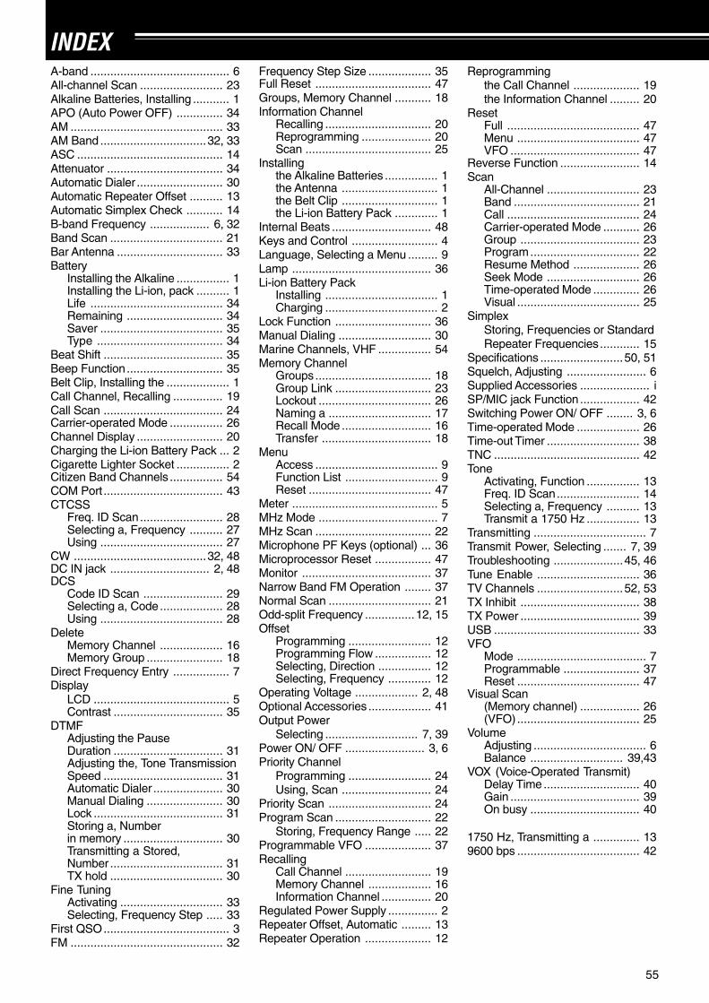
55
INDEXA-band .......................................... 6All-channel Scan ......................... 23Alkaline Batteries, Installing ........... 1APO (Auto Power OFF) .............. 34AM .............................................. 33AM Band ................................32, 33ASC ............................................ 14Attenuator ................................... 34Automatic Dialer .......................... 30Automatic Repeater Offset .......... 13Automatic Simplex Check ........... 14B-band Frequency .................. 6, 32Band Scan .................................. 21Bar Antenna ................................ 33Battery
Installing the Alkaline ................ 1Installing the Li-ion, pack .......... 1Life ........................................ 34Remaining ............................. 34Saver ..................................... 35Type ...................................... 34
Beat Shift .................................... 35Beep Function............................. 35Belt Clip, Installing the ................... 1Call Channel, Recalling ............... 19Call Scan .................................... 24Carrier-operated Mode ................ 26Channel Display .......................... 20Charging the Li-ion Battery Pack ... 2Cigarette Lighter Socket ................ 2Citizen Band Channels ................ 54COM Port .................................... 43CTCSS
Freq. ID Scan......................... 28Selecting a, Frequency .......... 27Using ..................................... 27
CW ........................................32, 48DC IN jack .............................. 2, 48DCS
Code ID Scan ........................ 29Selecting a, Code................... 28Using ..................................... 28
DeleteMemory Channel ................... 16Memory Group ....................... 18
Direct Frequency Entry ................. 7Display
LCD ......................................... 5Contrast ................................. 35
DTMFAdjusting the PauseDuration ................................. 31Adjusting the, Tone TransmissionSpeed .................................... 31Automatic Dialer ..................... 30Manual Dialing ....................... 30Lock ....................................... 31Storing a, Numberin memory .............................. 30Transmitting a Stored,Number .................................. 31TX hold .................................. 30
Fine TuningActivating ............................... 33Selecting, Frequency Step ..... 33
First QSO...................................... 3FM .............................................. 32
Frequency Step Size ................... 35Full Reset ................................... 47Groups, Memory Channel ........... 18Information Channel
Recalling ................................ 20Reprogramming ..................... 20Scan ...................................... 25
Installingthe Alkaline Batteries ................ 1the Antenna ............................. 1the Belt Clip ............................. 1the Li-ion Battery Pack ............. 1
Internal Beats .............................. 48Keys and Control .......................... 4Language, Selecting a Menu ......... 9Lamp .......................................... 36Li-ion Battery Pack
Installing .................................. 1Charging .................................. 2
Lock Function ............................. 36Manual Dialing ............................ 30Marine Channels, VHF ................ 54Memory Channel
Groups................................... 18Group Link ............................. 23Lockout .................................. 26Naming a ............................... 17Recall Mode ........................... 16Transfer ................................. 18
MenuAccess ..................................... 9Function List ............................ 9Reset ..................................... 47
Meter ............................................ 5MHz Mode .................................... 7MHz Scan ................................... 22Microphone PF Keys (optional) ... 36Microprocessor Reset ................. 47Monitor ....................................... 37Narrow Band FM Operation ........ 37Normal Scan ............................... 21Odd-split Frequency ...............12, 15Offset
Programming ......................... 12Programming Flow ................. 12Selecting, Direction ................ 12Selecting, Frequency ............. 12
Operating Voltage ................... 2, 48Optional Accessories ................... 41Output Power
Selecting ............................ 7, 39Power ON/ OFF ........................ 3, 6Priority Channel
Programming ......................... 24Using, Scan ........................... 24
Priority Scan ............................... 24Program Scan ............................. 22
Storing, Frequency Range ..... 22Programmable VFO .................... 37Recalling
Call Channel .......................... 19Memory Channel ................... 16Information Channel ............... 20
Regulated Power Supply ............... 2Repeater Offset, Automatic ......... 13Repeater Operation .................... 12
Reprogrammingthe Call Channel .................... 19the Information Channel ......... 20
ResetFull ........................................ 47Menu ..................................... 47VFO ....................................... 47
Reverse Function ........................ 14Scan
All-Channel ............................ 23Band ...................................... 21Call ........................................ 24Carrier-operated Mode ........... 26Group .................................... 23Program................................. 22Resume Method .................... 26Seek Mode ............................ 26Time-operated Mode .............. 26Visual ..................................... 25
SimplexStoring, Frequencies or StandardRepeater Frequencies............ 15
Specifications .........................50, 51Squelch, Adjusting ........................ 6Supplied Accessories ..................... iSP/MIC jack Function .................. 42Switching Power ON/ OFF ........ 3, 6Time-operated Mode ................... 26Time-out Timer ............................ 38TNC ............................................ 42Tone
Activating, Function ................ 13Freq. ID Scan......................... 14Selecting a, Frequency .......... 13Transmit a 1750 Hz ................ 13
Transmitting .................................. 7Transmit Power, Selecting ....... 7, 39Troubleshooting .....................45, 46Tune Enable ............................... 36TV Channels ..........................52, 53TX Inhibit .................................... 38TX Power .................................... 39USB ............................................ 33VFO
Mode ....................................... 7Programmable ....................... 37Reset ..................................... 47
Visual Scan(Memory channel) .................. 26(VFO)..................................... 25
VolumeAdjusting .................................. 6Balance ............................ 39,43
VOX (Voice-Operated Transmit)Delay Time............................. 40Gain ....................................... 39On busy ................................. 40
1750 Hz, Transmitting a .............. 139600 bps ..................................... 42