14.pdf
TRANSCRIPT

942 IEEE TRANSACTIONS ON POWER ELECTRONICS, VOL. 24, NO. 4, APRIL 2009
Sensorless Maximum Power Point Tracking of Windby DFIG Using Rotor Position Phase Lock Loop
(PLL)Baike Shen, Member, IEEE, Bakari Mwinyiwiwa, Member, IEEE, Yongzheng Zhang, Student Member, IEEE, and
Boon-Teck Ooi, Life Fellow, IEEE
Abstract—This paper presents an invention, the rotor positionphase lock loop (PLL), which enables maximum power point(MPPT) tracking of wind by doubly-fed induction generatorswithout needing a tachometer, an absolute position encoder, oran anemometer. The rotor position PLL is parameter variationinsensitive, requiring only an estimate of the magnetization induc-tance for it to operate. It is also insensitive to noise in the electricalmeasurements. Proof of concept is by: 1) digital simulations and2) experimental testing of a laboratory prototype.
Index Terms—Decoupled - control, doubly-fed inductiongenerator (DFIG), maximum power point tracking, wind turbinegenerator (WTG).
I. INTRODUCTION
W HEN no anemometer is used in maximum power pointtracking (MPPT) of wind, the method currently quali-
fies as sensorless [1]–[5]. A more demanding definition of sen-sorless MPPT would require that not only anemometers butalso tachometers and absolute position encoders are not used.The first stage of “true” sensorless MPPT of wind power by
Manuscript received July 29, 2008; revised October 05, 2008. First publishedMarch 27, 2009; current version published nulldate. This work was supportedby the Natural Science and Engineering Research Council of Canada under anIdea to Invention (I2I) Grant. Recommended for publication by Associate EditorZ. Chen.
B. Shen is with British Columbia Transmission Corporation, Vancouver, BCV3N 0A9, Canada (e-mail: [email protected]).
B. Mwinyiwiwa is with the Department of Electrical Power Engineering,College of Engineering and Technology, University of Dar-es-Salaam, Dar-es-Salaam, Tanzania (e-mail: [email protected]).
Y. Zhang and B.-T. Ooi are with the Department of Electrical Engi-neering, McGill University, Montreal, QC H3A 2A7, Canada (e-mail:[email protected]; [email protected]).
Digital Object Identifier 10.1109/TPEL.2008.2009938
doubly-fed induction generator (DFIGs) has consisted of mas-tering rotor-side control using back-to-back voltage source con-verters (VSCs) [1], [5]–[9 ]. The second stage consists of re-placing the absolute position encoder required for decoupled
- control by a sensorless means [10]–[18]. Presently, sen-sorless methods for DFIGs rely on solving for the rotor positionby fitting voltage and current measurements to the DFIG equa-tion, assuming knowledge of the parameters of the DFIG. Rotorspeed is then obtained by differentiating the rotor position withrespect to time.
In previous conference papers [14]–[16], the authors pre-sented an alternate method based on phase lock loop (PLL)principle that enables both the rotor speed and the rotor po-sition to be estimated simultaneously. This paper improveson [14]–[16 ] by incorporating robustness with respect to: 1)parameter variations and 2) noise in the transducer measure-ments. A U.S. patent [17] has been sought for the invention,which is given the name rotor position PLL. Like [18], therobust features come from exploiting physical relationships inthe induction machine: the rotor magnetic flux demagnetizesthe stator magnetic flux leaving behind the magnetization fluxof the stator voltage.
As in [2] and [3], the implementation of MPPT is alsophysics-based (Newton’s law of motion) and this is in contrastwith papers that make use of sophisticated mathematical tools[1], [4], [5].
The paper validates claims on the capability of the rotor po-sition PLL by digital simulations and by laboratory tests on a5 hp wound-rotor induction machine with back-to-back VSCs(see Appendixes A and B). The claim on sensorless MPPT ca-pability is justified by digital simulation of a wind turbine gener-ator (WTG) driven by wind from realistic wind velocity time-se-ries data.
(1)
0885-8993/$25.00 © 2009 IEEE

SHEN et al.: SENSORLESS MAXIMUM POWER POINT TRACKING OF WIND BY DFIG USING ROTOR POSITION PHASE LOCK LOOP (PLL) 943
The organization of the paper is as follows: Section II brieflyreviews the theory of induction machine in relation to decou-pled - control of a DFIG. Section III presents the principleof operation of the rotor position PLL. Section IV describes thedecoupled - control of the laboratory DFIG. Sections V andVI offer proofs of claims by simulations and laboratory experi-ments, respectively. Section VII presents the principle of MPPTusing the rotor position PLL only. Proof of claim is by digitalsimulation. Conclusions are made in Section VIII.
II. DECOUPLED - CONTROL OF DFIG
A. Theory of DFIG
The dynamics of the doubly-fed induction machine in the– coordinate frame are described by the differential equations
of (1), as shown at the bottom of the next page.The formulas of real power and reactive power of the
stator are: and .The rotor position PLL enables the rotor axes to be aligned withthe stator axes so that . The stator-side real power is then
and the reactive power . This desirablecondition allows and to be controlled independently by thestator current references and ,respectively, where the sign is used to indicate that the variableis a reference value.
The DFIG is controlled from the rotor-side. Neglecting the/dt terms and solving from the first and second row of (1), therotor current references are and
(2)
Neglecting the /dt terms is an assumption made by manyresearchers, including [8].
In induction machines, the magnetization reactance isdesigned to be very large so that the rotor windings can be in-duced by the stator windings across the airgap. Typically, theleakage reactances and the resistances are less than 2% of(see Appendix B for the parameters of the prototype), and there-fore, can also be neglected. Making the approximation, (2) be-comes
(3)
The assumptions are justified by simulation and experimentaltest results.
B. Induction Machine Principles
This section reviews induction machine principles relevant torotor position PLL. Derived from (1), the equivalent circuit ofthe induction machine in the – frame is shown in Fig. 1. Based
Fig. 1. γ–δ equivalent circuit of induction machine.
on Kirchhoff’s current law at the nodes of the mutual inductance
(4)
where is the vector of the magnetization currents.
On transforming from the synchronously rotating – frameto the stationary – frame, (4) becomes
(5)
In the – frame, the currents in (5) are at supply frequencyof the stator voltage. Writing
(6)
it follows from (5) that the rotor currents are
(7)
Equation (7) describes the requirement in physics that themagnetic flux space vector of the rotor currents is equal and op-posite to the magnetic flux space vector of the stator side cur-rents together with the magnetization currents.
The rotor currents measured by current sensors are ( ,) in the – frame at angular frequency . The – framecurrents are related to – frame currents by
(8)
where the frame transformation matrix is
(9)

944 IEEE TRANSACTIONS ON POWER ELECTRONICS, VOL. 24, NO. 4, APRIL 2009
Fig. 2. Schematic of rotor position PLL.
and where is the angular position of the rotor.The information regarding the speed and the angle arelost on transforming from the – frame to the – frame andthereafter to the – frame. The objective of the rotor positionPLL is to recover ( ).
III. ROTOR POSITION PLL
Fig. 2 is the schematic of the rotor position PLL. Its measure-ment inputs are: three-phase stator currents, three-phase rotorcurrents, and three-phase stator voltages. The a–b–c quantitiesare first converted to – quantities. Because of open neutralY connections of the stator and the rotor windings, the zerosequences are dropped. The – stator currents ( ) arecos(..) and sin(..) functions of the argument ( ) andthe – rotor currents ( ) are cos(..) and sin(..) func-tions of the argument ( ). The stator voltages ( )after passing through the block yield the magnetiza-tion currents ( ). The stator side currents ( ) and( ) are summed to form ( , ) of (6).
Fig. 2 has the traditional “voltage-controlled oscillator(VCO)” block and the detector block of a PLL. The VCO con-sists of the -I block and the integrator 1/s block after the errorsignal , which is the output of the detector. The output of the
-I block is . A central frequency , close to the statorfrequency is added and the sum is treated as an algebraicunknown to track the rotor speed . After the integrator 1/Sblock, the argument is formed to track therotor position. The variable is the algebraic unknown totrack rotor position. The outputs of the cos and sin blocks are
and . The blockimplements the transformation of the rotor currents ( )to
(10)
Note that replaces in(8) and (9). The rotor position PLL applies (10) to replicate theinduction machine transformation of (8).
At this point, (7) is generalized by letting the rotor currentsin the d–q frame to take the time function of the general form
(11)
As will be seen later, this step is taken as an easy way to provethat the rotor position PLL is insensitive to measurement noise.From (7)
(12)
Essentially, the measurement noise is on both the stator andthe rotor side because of the induction process. Substituting (11)in (8)
(13)
Substituting (13) in (10)
(14)
where Whenand
(15)
Equating (15) and (12), it follows that
(16)
The condition in which decoupled - control can be im-plemented is satisfied when and because onback substitution from (16), (4) of the – frame is satisfied.
The tracking of the rotor speed and the rotor positionby the algebraic unknowns and is accomplished by theVCO which reduces the error by negative feedback to zero.The error is computed by the detector as
(17)
On substituting (12) and (14), the error is
(18)

SHEN et al.: SENSORLESS MAXIMUM POWER POINT TRACKING OF WIND BY DFIG USING ROTOR POSITION PHASE LOCK LOOP (PLL) 945
Fig. 3. DFIG with slip controls.
The error drives the VCO in negative feedback until theargument in the sine function is zero. This is whenand .
A. Robustness With Respect to Noise
From (18), the method is robust because any noise in the cur-rent measurements is in [ ] and not in the argumentof the sin(..) function. This property is a consequence of physicsbecause noise on the stator side in (12) is electromagnetically in-duced in the rotor currents in (11).
B. Robustness With Respect to Parameters of DFIG
Another robustness feature of the rotor position PLL is evi-dent from (17) . The error is formed from current measurements.Only the magnetization currents are not measured. They are esti-mated from the stator voltages and the magnetization inductance
. No other machine parameters are required for the tracking.As the magnetization reactance is designed by manufacturersto be as large as possible in induction machines, the magneti-zation currents ( ) are small, and for this reason, highaccuracy in measuring is not required. This is confirmed inexperimental results that show that decoupled - operation ispossible over an extensive operating range even when the mag-netization inductance is assumed to be infinite.
C. Design Considerations
The transfer function , which lies between thedetector error and the frequency deviation , is a filterof noise from current measurements. Therefore, it is desir-able to keep as small as possible. Unfortunately, whenis too small, the window of frequency acquisition is small.Since the rotor frequency varies between (1.0 0.3) and(1.0+0.3) , (for operation with maximum slip of 0.3),
must be kept reasonably large. For this reason, the speedmeasurement is noisy as will be seen in the experimental mea-surements (see Fig. 11). The noise in the angle measurement isreduced by the 1/ block. From (18), tracking is not determinedby the size of the currents that appear as [ ], butby the frequency and the angle in the argument of the sinefunction, i.e., [ ]. Therefore, accuracyis not affected when the power and current levels are low. The
- gain constants of Fig. 2 have been chosen by trial and errorwith the help of commercial real-time rapid control prototypingequipment.
Fig. 4. Block diagram of rotor-side VSC control of DFIG.
IV. IMPLEMENTATION OF DECOUPLED - CONTROL OF DFIG
Fig. 3 shows the grid-side VSC and the rotor-side VSC inback-to-back rotor-side control of the DFIG. The grid-side VSCconveys the slip power automatically to the 60 Hz ac grid byusing its active power control to maintain the voltage across theregulated dc capacitors. Little else needs to be added regardingthe grid-side VSC because the control technique is well known.A 3-phase transformer matches the high grid-side voltage to thelow voltage of the VSCs.
Fig. 4 shows the rotor-side control that implements the de-coupled - control. The commands are taken from the ,
Reference Generator that issues the references , . Thestator current references and areconverted to rotor current references and through (3).Since true control is by the rotor voltages ( and ),the rotor current references are produced by negative feedback.The rotor currents ( and ) are measured, transformedto the – frame as ( ) and - gains ensure that ( )are tracked by negative feedback. Trial and error with real-time,rapid control prototyping equipment has been used to select theproportional and integral gain constants to ensure fast and stableoperation. The transformations to and from – and – framesare by the transformation blocks that make use of , thephase angle of the stator voltage from the stator voltage PLL.The transformations to and from – and – frames are by the
transformation blocks that make use of , the es-timate of the position of the rotor winding axis coming from therotor position PLL.
Although there is the option to control for voltage supportand voltage regulation, this paper is concerned only with realpower control of for MPPT. Thereceives the rotor speed estimate from therotor position PLL. The power reference block computes
to load the DFIG. This is explained inSection VII that discusses the principle of MPPT implemen-tation without an anemometer. Before proceeding to MPPT,simulation and laboratory test results are presented to showthat the rotor position PLL lives up to the claims of beinginsensitive to parameter variations and to measurement noisewhile implementing decoupled - control.
V. PROOFS OF SPEED AND POSITION TRACKING BY
SIMULATIONS
Because the laboratory does not have an absolute position en-coder to calibrate the rotor position PLL, simulations are ap-

946 IEEE TRANSACTIONS ON POWER ELECTRONICS, VOL. 24, NO. 4, APRIL 2009
Fig. 5. Fast response of rotor position PLL. (a) Transient test of speed estima-tion. (b) Transient test of position estimation.
plied to fill this gap. Simulation is by EMTP-RV, a commercialgrade software that has software models of DFIGs, dc motors,and speed and position transducers. Detail insulated gate bipolartrasistor switchings of the back-to-back VSC under sinusoidalpulsewidth modulation are simulated.
A. Response Time of Speed and Position Tracking
In this simulation test, a dc motor drives the DFIG at a con-stant speed and its rotor position is a ramp. At 400 ms,the rotor position PLL of Fig. 2 is activated. The dotted linesin Fig. 5(a) and (b) are from the transducers of EMTP-RV. Thesolid lines are from the rotor position PLL. The solid line ofthe rotor position overlaps the dotted line but is deliberately dis-placed in Fig. 5(b) for clarity. The estimated rotor speed has notbeen filtered.
B. Insensitiveness to Measurement Noise
Based on using the software position transducer as reference,Fig. 6 shows that the error of the rotor position PLL is around0.11 , an accuracy lying between an 11- and a 12-bit absoluteposition encoder. The noise in the current measurement appearsas fluctuation [ ] around the average. In order toshow that the rotor position PLL is insensitive to noise, at
s the three-phase ac voltage supply of the DFIG injects 5thand 7th voltage harmonics, each in the order of 10%. Fig. 6shows that after the transient has damped out, the average, whichaccording to (18) is the estimated position, is unaffected.
VI. PROOF OF CONCEPTS BY LABORATORY EXPERIMENTS
Appendixes A and B present detailed descriptions of the labo-ratory test equipment. In order to subject the rotor position PLLunder severe conditions, the tests have been conducted under
Fig. 6. Simulated error of rotor position PLL using the software position trans-ducer as reference.
Fig. 7. Experimental three-phase current waveforms. (a) Rotor (2.4 Hz). (b)Stator (60 Hz).
noisy conditions. Because of slight three-phase voltage unbal-ance, there is some negative sequence. Because of transformersaturation, there are and voltage harmonics. As themeasurements of and show, the waveforms are fuzzy. Thefuzziness is testimony that the rotor position PLL is insensitiveto noise and allows the DFIG to operate under decoupled -control.
Lest critics insist that the fuzziness comes from the rotor po-sition PLL, a “calibration” test has been conducted in which thewound rotor induction machine runs as a wound rotor induc-tion motor, without rotor position PLL. This test shows that thefuzziness is also measured. Because of space limit, the test re-sults are withheld.
A. Static Test
Fig. 7 shows the quality of the 3-phase rotor currents in (a)and the three-phase stator currents in (b). Fig. 8 shows the fastFourier transforms (FFTs) of the waveforms of one currentphase of Fig. 7. The dominant frequency of the stator currentis 60 Hz and its slip frequency on the rotor side is 2.4 Hz. TheFFT of the stator current shows the 120 Hz (2nd harmonic)

SHEN et al.: SENSORLESS MAXIMUM POWER POINT TRACKING OF WIND BY DFIG USING ROTOR POSITION PHASE LOCK LOOP (PLL) 947
Fig. 8. FFT of experimental current waveforms. (a) Rotor (signal 2.4 Hz). (b)Stator (signal 60 Hz).
Fig. 9. Experimental results on responses to step changes in stator references� and � .
Fig. 10. Two separate experimental results on complex power step response.(a) Real power. (b) Reactive power.
from unbalance, the 180 Hz (3rd harmonic), and the 300 Hz(5th harmonic) from magnetic saturation. Besides currentharmonics, voltage harmonics make significant contributionsto waveform distortion in and measurements.
Fig. 11. Rotor PLL estimate of rotor speed � � � .
B. Tests on Decoupled - Control
Fig. 9 shows the stator complex power and of the pro-totype in response to step changes in the references,and . Generation real power is plotted as negativevalues. The experiment has been planned to demonstrate the de-coupling of and control over a wide operating range. Instep changes of from 1500 to 2000 and to 2500 W,disturbances in are hardly noticeable. The converse applies.The noises in and are due to noise from slight unbalanceand magnetic saturation.
Fig. 10(a) and (b) is taken from two separate experiments. Thefigure shows, on an expanded time scale, the step responses ofFig. 9. The settling time of is within 0.26 s and that ofis within 0.36 s. As the wind turbine blades have moments ofinertia of the order of s, no effort has been made toshorten the time of response further.
C. Test on Capability to Implement MPPT
Our method of MPPT is to input the rotor speed to the ,reference generator block in Fig. 4 . The reference power
is computed as . In the test experiment, thedc motor is made to vary the rotor speed cyclically from sub-synchronous to supersynchronous speed and Fig. 11 shows thespeed estimates of the rotor position PLL. The speed estimateis taken from in Fig. 2. Its envelope is noisy because the -
block provides the only filtering of [ ] of (18). The simulated speed in Fig. 5 is free of noise indicating thatthe noise comes from the ac supply as recorded in Fig. 8. Thenoise can be removed by a low-pass filter without causing in-stability in MPPT operation. The position measurement is verymuch cleaner because the 1/ block attenuates the 120 Hz by afactor of 0.0013, for example. Fig. 12 shows the power output
tracking the reference .
D. Test on Sensitivity to Parameter Variation
Fig. 13 displays experimental results in a test similar to Fig. 9but with the difference that the magnetization in the rotor posi-tion PLL is assumed to be . In the test of Fig. 9,the measured magnetization reactance of 39.6 of the test ma-chine has been used. Fig. 13 shows that operation is possible at1500 W and higher. Instability sets in when the stator and rotorwinding currents are low, comparable to the magnetization cur-rents. This experiment demonstrates the high insensitiveness to
948 IEEE TRANSACTIONS ON POWER ELECTRONICS, VOL. 24, NO. 4, APRIL 2009
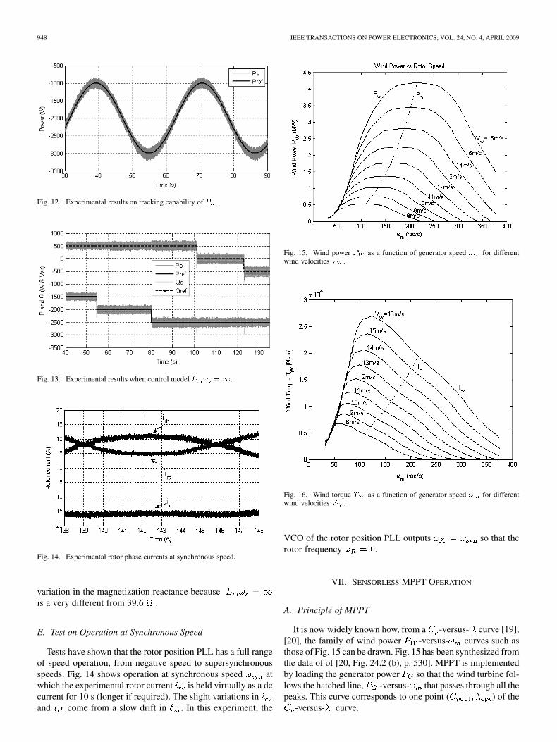
Fig. 12. Experimental results on tracking capability of � .
Fig. 13. Experimental results when control model � � ��.
Fig. 14. Experimental rotor phase currents at synchronous speed.
variation in the magnetization reactance becauseis a very different from 39.6 .
E. Test on Operation at Synchronous Speed
Tests have shown that the rotor position PLL has a full rangeof speed operation, from negative speed to supersynchronousspeeds. Fig. 14 shows operation at synchronous speed atwhich the experimental rotor current is held virtually as a dccurrent for 10 s (longer if required). The slight variations inand come from a slow drift in . In this experiment, the
Fig. 15. Wind power � as a function of generator speed � for differentwind velocities � .
Fig. 16. Wind torque � as a function of generator speed � for differentwind velocities � .
VCO of the rotor position PLL outputs so that therotor frequency .
VII. SENSORLESS MPPT OPERATION
A. Principle of MPPT
It is now widely known how, from a -versus- curve [19],[20], the family of wind power -versus- curves such asthose of Fig. 15 can be drawn. Fig. 15 has been synthesized fromthe data of of [20, Fig. 24.2 (b), p. 530]. MPPT is implementedby loading the generator power so that the wind turbine fol-lows the hatched line, -versus- that passes through all thepeaks. This curve corresponds to one point ( ) of the
-versus- curve.

SHEN et al.: SENSORLESS MAXIMUM POWER POINT TRACKING OF WIND BY DFIG USING ROTOR POSITION PHASE LOCK LOOP (PLL) 949
Sensorless MPPT of this paper makes use of Newton’ law ofmotion in the rotational frame. In the per unit system of powersystems engineering, it is expressed as
(19)
where is the inertia constant in seconds, is the perunit wind power, and is the per unit generated power ofthe DFIG. In order to appreciate the principle of automatictracking without an anemometer, the -versus- curvesof Fig. 15 are redrawn as -versus- curves of Fig. 16.The cubic generator power -versus- curve is redrawn asthe quadratic generator countertorque -versus- curve. InFig. 16, the intersection of the -versus- curve for a givenwind velocity with the -versus- curve represents theequilibrium operating point. Should the rotor speed behigher than the equilibrium rotor speed, from Fig. 16,and from (19), the rotor would decelerate. On the other hand, if
is lower than the equilibrium rotor speed, and therotor would accelerate. Therefore, for any wind velocity ,the turbine speed changes until the wind torque findsan equilibrium with the optimum countertorque , which iscontrolled by the reference generator block in Fig. 4.Since all the intersection points lie on the right-hand side ofthe peak wind torques in the family of wind velocity curves,the equilibrium points are all stable. Because the wind velocityfluctuates, the rotor speed keeps changing to track the optimumpower of the wind velocity.
B. Designing Reference
, in the reference generator block in Fig. 4, controls thestator power. Neglecting ohmic losses, the stator power is, frominduction machine theory, the airgap power
(20)
where is the induction machine torque output and is thesynchronous speed of the grid frequency. The electromechan-ical output power of the induction machine is
(21)
is the algebraic sum of the stator power and the rotorpower, which, as shown in Fig. 3, passes through the rotor sliprings and the grid-side VSC. For MPPT, one designs so thatit follows -versus - curve of Fig. 15. can be equatedas
(22)
where is a proportionality constant. Equating andeliminating by substituting (20), the power reference in Fig.4 must compute
(23)
Fig. 17. Simulation of (a) � wind power, � DFIG electrical power; (b)DFIG speed; (c) � ��� –-MPPT strategy.
The speed is obtained from the rotor position PLL.
C. Proof of Sensorless MPPT by Simulation
A 600-s wind velocity file is used to conduct the simulationtest. The average wind velocity is 12 m/s and the WTG hasan inertia constant of s. Fig. 17(a) displays a sampleof the simulated wind power and generated power .Fig. 17(b) shows the rotor speed (per unit) that accelerateswhen , and decelerates when . The rotorspeed carries the power reference withit. As proof of successful MPPT, the value of is computedfrom the simulated values of and for fluctuatingwind velocity . Fig. 17(c) shows fluctuating slightlybelow the optimum value of . (The quoted value isthe mechanical power efficiency coefficient. As pointed out by[20], when mechanical losses are deducted, takes a valuethat is usually lower than 0.5.) The slight inaccuracy (about 2%)is related to the fact that Fig. 15 has a family of flat maxima sothat there is uncertainty in determining the constant of (22).Nevertheless, the simulation is sufficient to validate the claimthat MPPT is achieved without an anemometer. As the rotor po-sition PLL replaces the mechanical tachometer and absolute po-sition encoder, the MPPT is sensorless in the demanding defini-tion.
VIII. CONCLUSION
Simulations using wind velocity from a data file have shownthat sensorless MPPT is achievable using the rotor position PLLalone. Because the rotor position PLL is a new invention [17],this paper has devoted space in describing the operating prin-ciples. Simulation and experimental results have demonstratedthat the rotor position PLL has the following attractive features.
1) Parameter Insensitivity—Except for a coarse estimate ofthe magnetization inductance, no other induction parame-ters are required for it to operate. Because the method doesnot depend on accurate parameter values, there is no per-formance deterioration associated with winding resistancechanges with temperature or inductance changes with sat-uration.
2) Measurement Noise Insensitivity—This robustness is in-herent in the operating principle.

950 IEEE TRANSACTIONS ON POWER ELECTRONICS, VOL. 24, NO. 4, APRIL 2009
Fig. 18. Layout of experiment test equipment.
Fig. 19. Laboratory DFIG and dc machine.
APPENDIX
APPENDIX A: EXPERIMENTAL TEST EQUIPMENT
Fig. 18 shows the experimental test layout. Figs. 19 and 20are photographs of the equipment.
APPENDIX
APPENDIX B: PARAMETERS OF DFIG
DFIG (wound rotor induction machine)Measured parameters: , ,
mH, mH.
ACKNOWLEDGMENT
The authors thank Prof. G. Joos for the use of real-time rapidcontrol prototyping equipment of Opal-RT and Mr. K. Gogasfor initiating them on its use. One of the authors (B.M.) thanksthe University of Dar-es-Salaam, Tanzania, for leave of absenceto do research at McGill University.
REFERENCES
[1] S. Bhowmik, R. Spee, and J. H. R. Enslin, “Performance optimiza-tion for doubly fed wind power generation systems,” IEEE Trans. Ind.Appl., vol. 35, no. 4, pp. 949–958, Jul.–Aug. 1999.
Fig. 20. Laboratory power electronic converters and digital controller.
[2] W. Lu and B.-T. Ooi, “ Multiterminal LVDC system for optimal acqui-sition of power in wind-farm using induction generators,” IEEE Trans.Power Del., vol. 17, no. 4, pp. 558 –563, Jul. 2002.
[3] W. Lu and B.-T. Ooi, “ Optimal acquisition and aggregation ofoffshore wind power by multiterminal voltage-source HVDC,” IEEETrans. Power Del., vol. 18, no. 1, pp. 201 –206, Jan. 2003.
[4] H. Li, K. L. Shi, and P. G. McLaren, “Neural-network-based sensorlessmaximum wind energy capture with compensated power coefficient,”IEEE Trans. Ind. Appl. , vol. 41, no. 6, pp. 1548–1556, Nov.-Dec. 2005.
[5] W. Qiao, W. Zhou, J. M. Aller, and R. G. Harley, “Wind speed esti-mation based sensorless output maximization control for a wind tur-bine driving a DFIG,” IEEE Trans. Power Electron., vol. 23 , no. 3, pp.1156–1169, May 2008.
[6] R. Pena, J. C. Clare, and G. M. Asher, “Doubly fed induction gen-erator using back-to-back PWM converters and its application to vari-able-speed wind-energy generation,” in Proc. Inst. Electr. Eng., B, May1996, vol. 143, no. 3, pp. 231–241.
[7] S. Muller, M. Deicke, and R. W. De Doncker, “Doubly fed inductiongenerator systems for wind turbines,” IEEE Ind. Appl. Mag., vol. 8, no.3, pp. 26–33, May–Jun. 2002.
[8] H. Akagi and H. Sato, “ Control and performance of a doubly-fed in-duction machine intended for a flywheel energy storage system ,” IEEETrans. Power Electron., vol. 17, no. 1, pp. 109–116, Jan. 2002.
[9] K. Protsenko and D. Xu, “ Modeling and control of brushlessdoubly-fed induction generators in wind energy applications,” IEEETrans. Power Electron., vol. 23, no. 3, pp. 1191–1197, May 2008.
[10] L. Xu and W. Cheng, “ Torque and reactive power control of a doublyfed induction machine by position sensorless scheme,” IEEE Trans.Ind. Appl., vol. 31, no. 3, pp. 636 –642, May/Jun. 1995.
[11] L. Morel, H. Godfroid, A. Miraian, and J. M. Kauffmann, “Doubly-fedinduction machine: Converter optimization and field oriented controlwithout position sensor,” in Proc. Inst. Electr. Eng., B, Jul. 1998, vol.145, no. 4, pp. 360–368 .
[12] R. Cardenas, R. Pena, J. Proboste, G. Asher, and J. Clare, “MRAS ob-server for sensorless control of standalone doubly fed induction gener-ators,” IEEE Trans. Energy Convers., vol. 20, no. 4, pp. 710– 718, Dec.2005.
[13] R. Cardenas, R. Pena, J. Clare, G. Asher, and J. Proboste, “MRASobservers for sensorless control of doubly-fed induction generators,”IEEE Trans. Power Electron., vol. 23, no. 3, pp. 1075–1084 , May 2008.
[14] B. Shen, V. Low, and B. T. Ooi, “Slip frequency phase lock loop (PLL)for decoupled P-Q control of doubly-fed induction generator (DFIG),”in Proc. 2004 IEEE Ind. Electron. Soc. Conf., Busan, South Korea, Nov.

SHEN et al.: SENSORLESS MAXIMUM POWER POINT TRACKING OF WIND BY DFIG USING ROTOR POSITION PHASE LOCK LOOP (PLL) 951
[15] B. Shen and B. T. Ooi, “ Novel sensorless decoupled P-Q control ofdoubly-fed induction generator (DFIG) based on phase locking to g–dframe,” in Proc. 2005 Power Electron. Spec. Conf., Recife, Brazil, Jun.
[16] B. Shen and B. T. Ooi, “ Parameter-insensitive sensorless decoupledP-Q controller for doubly-fed induction generator ,” in Proc. 2007IEEE Power Electron. Spec. Conf., Jun., pp. 2102–2107.
[17] B. T. Ooi, B. Shenm, and V. Low , “System and method of controllinga doubly-fed induction generator,” U.S. Patent PCT/CA2007/002137Nov. 28 , 2007.
[18] R. Datta and V. T. Ranganathan, “A simple position-sensorless algo-rithm for rotor side field-oriental control of wound-rotor induction ma-chine,” IEEE Trans. Ind. Electron., vol. 48, no. 4 , pp. 786–793, Aug.2001 .
[19] S. Heier, Grid Integration of Wind Energy Conversion Systems.Chichester, U.K.: Wiley, 1998.
[20] T. Ackermann, Ed., Wind Power in Power Systems. Hoboken, NJ:Wiley, 2005.
Baike Shen was born in GuangXi, China. Hereceived the B.Eng. degree in electrical engineeringfrom Tsinghua University, Beijing, China, and theM.Eng. degree from McGill University, Montreal,QC, Canada.
He was with GuangXi Power Company. Currently,he is with British Columbia Transmission Corpora-tion, Vancouver, BC, Canada. His current research in-terests include power electronics and power systems.
Bakari Mwinyiwiwa received the B.Sc. (Eng.)degree from the University of Dar-Es-Salaam,Dar-Es-Salaam, Tanzania, in 1985, and the M.Eng.and Ph.D. degrees from McGill University, Mon-treal, QC, Canada, in 1989 and 1997, respectively.
Currently, he is with the Department of Elec-trical Power Engineering, College of Engineeringand Technology, University of Dar-Es-Salaam.His current research interests include high-powerelectronics and applications.
Yongzheng Zhang received the M.A.Sc. degree inelectrical engineering from Concordia University,Montreal, QC, Canada. Currently, he is workingtoward the Ph.D. degree in the Department of Elec-trical and Computer Engineering, McGill University,Montreal.
His current research interests include renewableenergy conversion, and application of power con-verters for distributed system and electric machinedrives.
Boon-Teck Ooi (S’69–M’71–SM’85–F’03–LF’05)was born in Malaysia. He received the B.Eng.(Hons.) degree from the University of Adelaide,Adelaide, S.A., Australia, the S.M. degree from theMassachusetts Institute of Technology, Cambridge,and the Ph.D. degree from McGill University,Montreal, QC, Canada.
He is currently a Professor in the Department ofElectrical and Computer Engineering, McGill Uni-versity.