15-294 rapid prototyping technologies: stl files and
TRANSCRIPT

1
15-294 Rapid PrototypingTechnologies:
STL Files and Slicing Software
Dave TouretzkyComputer Science
Carnegie Mellon University

2
The STL File Format
● StereoLithography file– or –
Standard Tesselation Language● Originally developed by 3D Systems.● Now widely used for describing 3D surfaces
for CAD or printing.● Two flavors: ASCII or Binary.
3
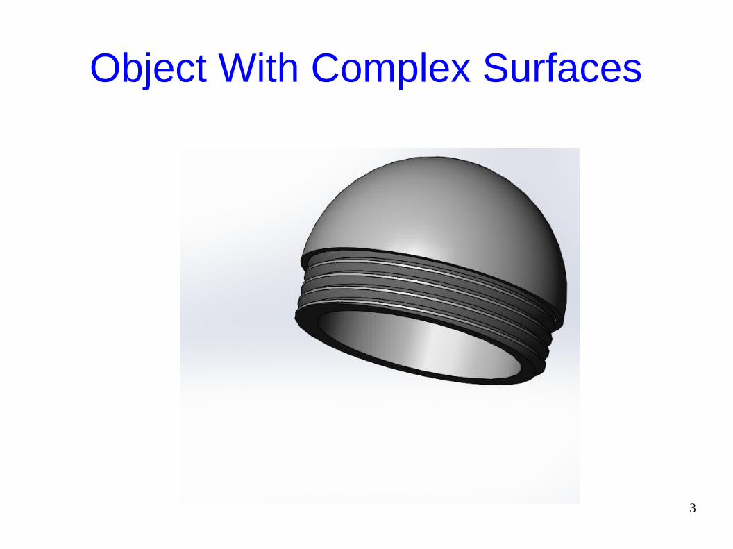
Object With Complex Surfaces
4
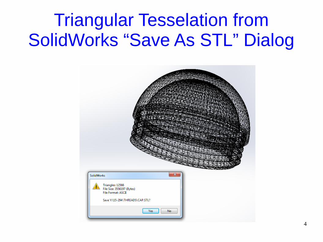
Triangular Tesselation fromSolidWorks “Save As STL” Dialog

5
ASCII STL File
solid <name>facet normal ni nj nk outer loop vertex v1x v1y v1z vertex v2x v2y v2z vertex v3x v3y v3z endloopendfacet…endsolid <name>

6
Binary STL File
UINT8[80] – Header (must not begin with “solid”)
UINT32 – Number of triangles
for each triangle:
REAL32[3] – Normal vector
REAL32[3] – Vertex 1 x,y,z
REAL32[3] – Vertex 2 x,y,z
REAL32[3] – Vertex 3 x,y,z
UINT16 – Attribute byte count (typically zero)
Some variants of STL store color information in the attribute byte count.

7
Python Code to Write STL Files
● See demo files in class STL directory.● Rules for STL creation:
– Triangles are flat (planar). To make a curved surface, use more triangles.
– Every vertex belongs to at least two triangles.
– No vertex can touch an edge of another triangle.

8
Example: Making a Cube
s = 3.0 # length of a side
# Eight corner points of a cube
p1 = (0, 0, 0) p2 = (0, 0, s) p3 = (0, s, 0) p4 = (0, s, s) p5 = (s, 0, 0) p6 = (s, 0, s) p7 = (s, s, 0) p8 = (s, s, s)
9
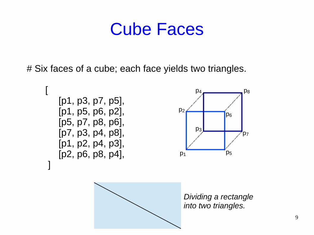
Cube Faces
# Six faces of a cube; each face yields two triangles.
[ [p1, p3, p7, p5], [p1, p5, p6, p2], [p5, p7, p8, p6], [p7, p3, p4, p8], [p1, p2, p4, p3], [p2, p6, p8, p4], ]
Dividing a rectangle into two triangles.
p1
p2
p3
p4 p8
p5
p6
p7
10
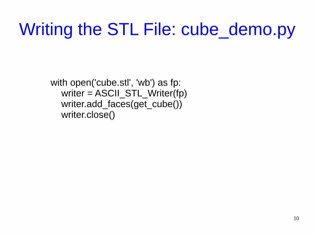
Writing the STL File: cube_demo.py
with open('cube.stl', 'wb') as fp: writer = ASCII_STL_Writer(fp) writer.add_faces(get_cube()) writer.close()

11
With Zero Surface Normals
12
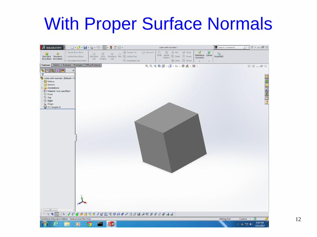
With Proper Surface Normals
13
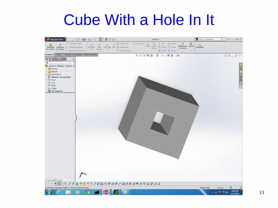
Cube With a Hole In It

14
The Stanford Bunny: Low Res
15
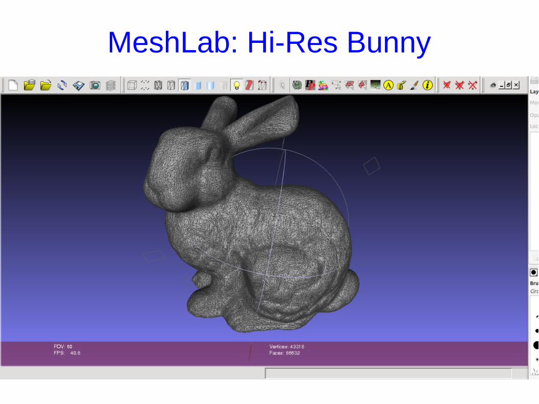
MeshLab: Hi-Res Bunny

16
Zooming In with MeshLab
17
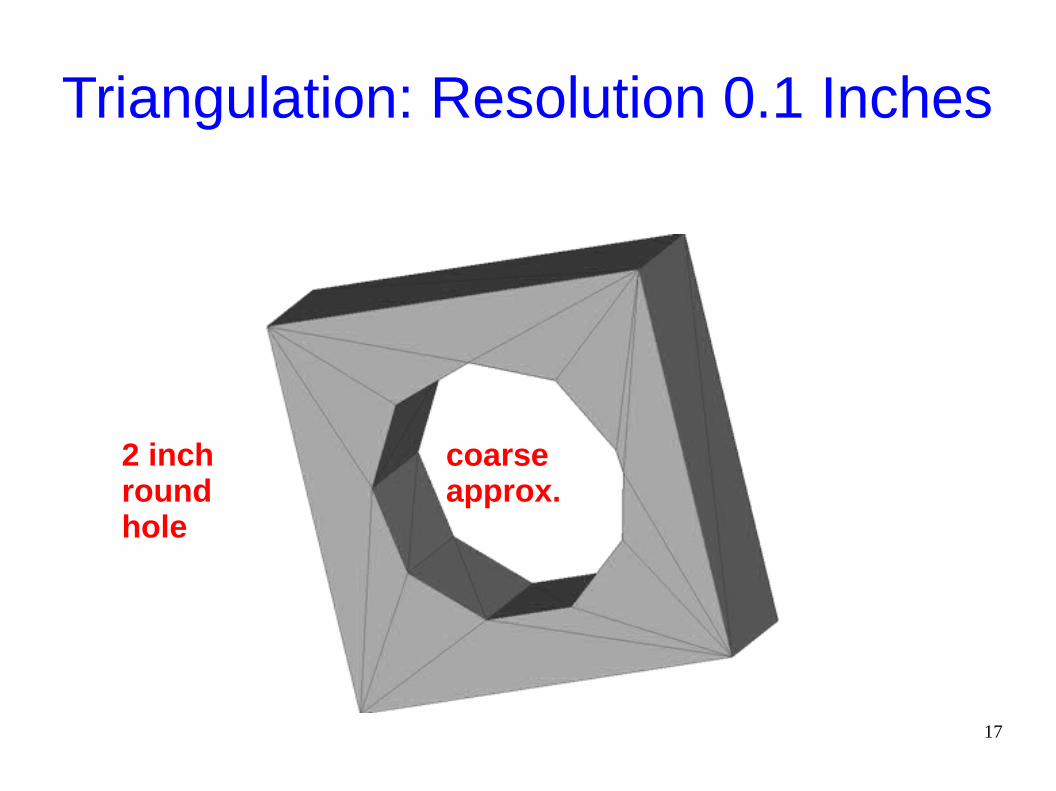
Triangulation: Resolution 0.1 Inches
2 inch round hole
coarseapprox.
18
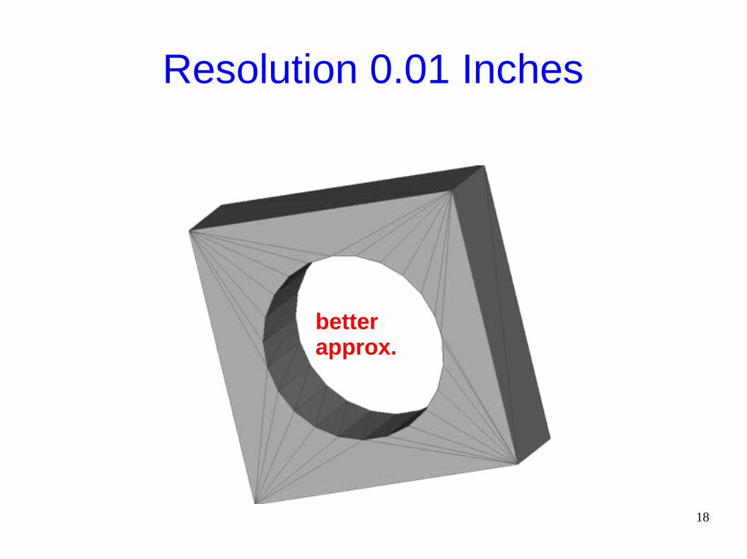
Resolution 0.01 Inches
betterapprox.

19
Resolution 0.001 Inches
smoothapprox.

20
Resolution 0.0001 Inches
toomuch

21
Chord Height = Max Distance from Actual Surface to the Facet
Choose a resolution that produces an acceptable chord height.
22
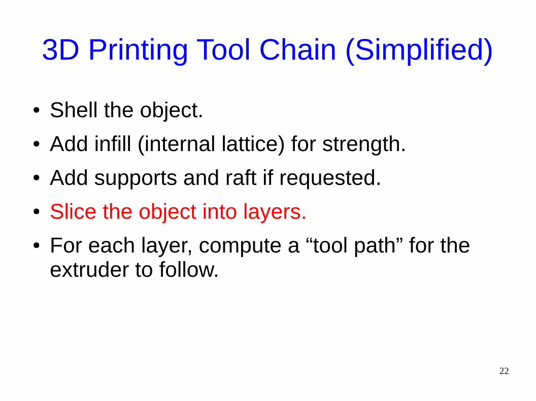
3D Printing Tool Chain (Simplified)
● Shell the object.● Add infill (internal lattice) for strength.● Add supports and raft if requested.● Slice the object into layers.● For each layer, compute a “tool path” for the
extruder to follow.

23
Slicing the Bunny
24
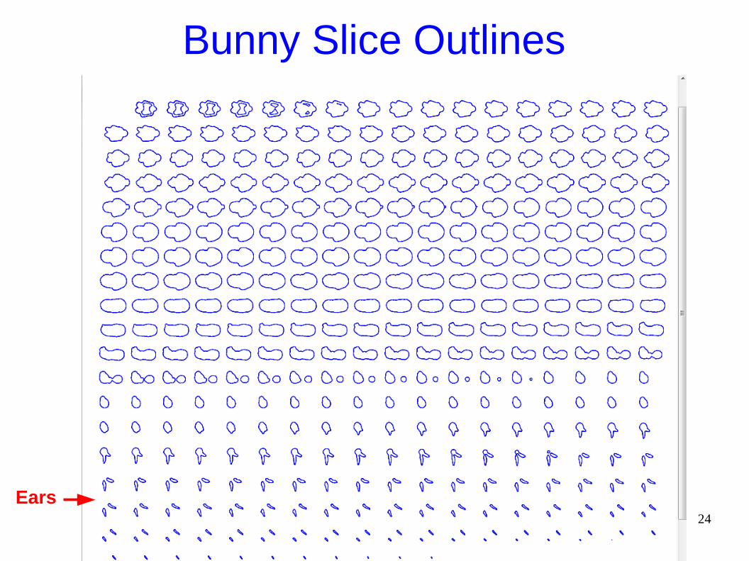
Bunny Slice Outlines
Ears
25
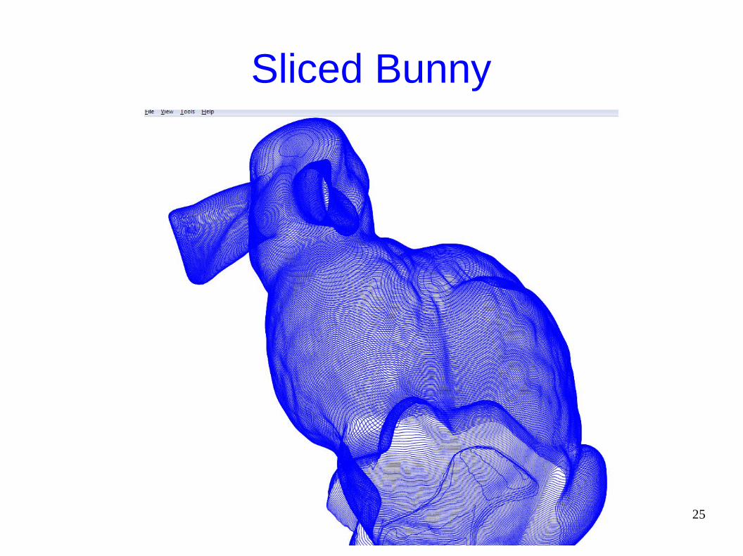
Sliced Bunny

26
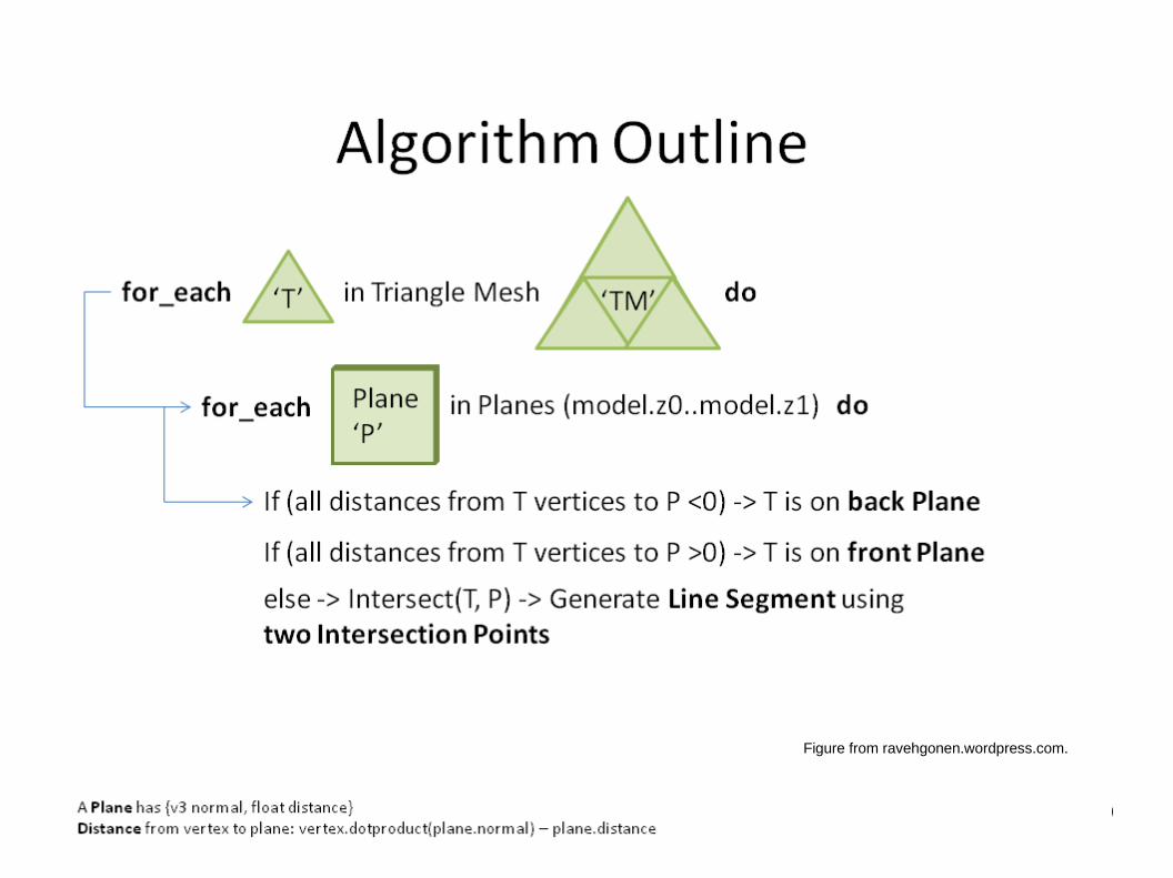
Slicing Algorithm
● Given the cutting plane orientation and the bounding box of the object, determine the number of slices (cutting planes).
● For each triangle in the mesh:● For each cutting plane:
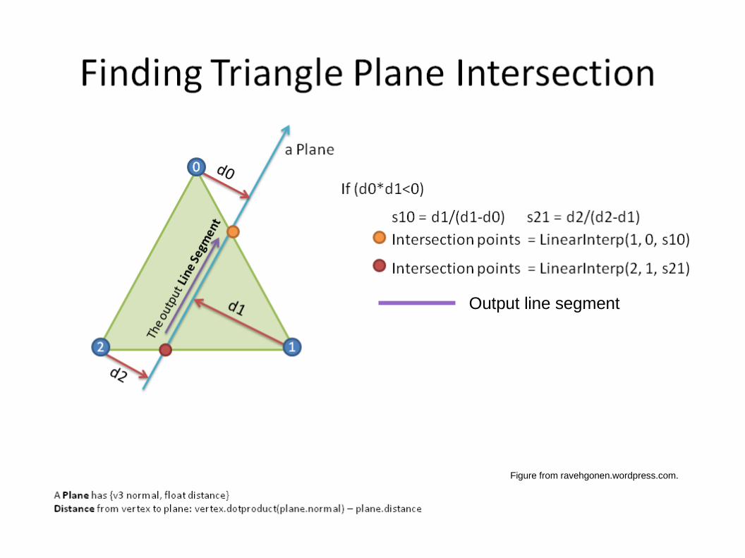
● Compute the intersection of the cutting plane and the triangle.● If the intersection contains exactly 2 points, add that line to
the list of line segments for that cutting plane.
● For each cutting plane:● Assemble the list of line segments to form a set of
continuous lines. These will be converted to tool paths.
27Figure from ravehgonen.wordpress.com.
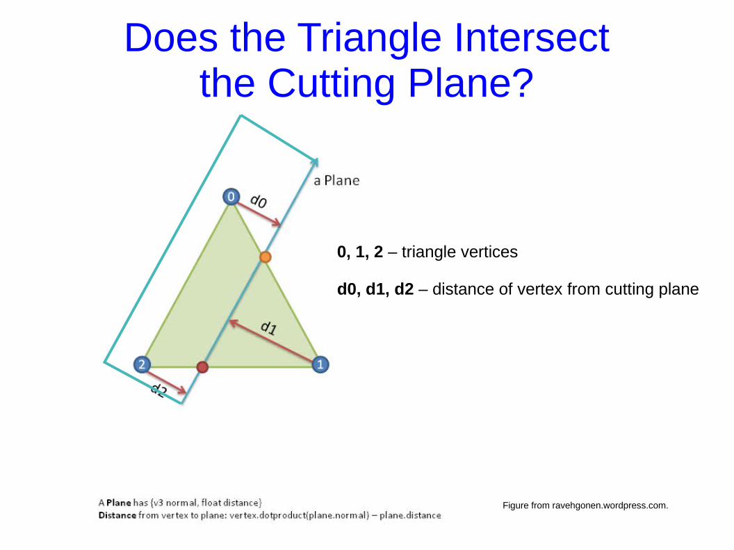
0, 1, 2 – triangle vertices
d0, d1, d2 – distance of vertex from cutting plane
Does the Triangle Intersectthe Cutting Plane?

28
Figure from ravehgonen.wordpress.com.
29
Figure from ravehgonen.wordpress.com.
30
Figure from ravehgonen.wordpress.com.
Output line segment

31
GCcode
● The output of the slicer program is typically a GCode file.
● GCode is used in many types of CNC machines. (CNC = Computerized Numerical Control)
● Includes commands to move the extruder to specified (x,y,z) coordinates, feed (or stop feeding) plastic, etc.

32
Popular Slicing Programs
● Slic3r● Cura● KISSlicer● Skeinforge