15-447 computer architecturefall 2007 © sep 10 th, 2007 majd f. sakr [email protected]...
Post on 22-Dec-2015
215 views
TRANSCRIPT
15-447 Computer Architecture Fall 2007 ©
Sep 10th, 2007
Majd F. [email protected]
www.qatar.cmu.edu/~msakr/15447-f07/
CS-447– Computer Architecture
M,W 10-11:20am
Lecture 4Instruction Set Architecture
15-447 Computer Architecture Fall 2007 ©
Done by nowDone by now
°Read the first 3 chapters of the book
°Review the slides
°Come see us during office hours
°Working on the project
15-447 Computer Architecture Fall 2007 ©
Program Concept
°Hardwired systems are inflexible
°General purpose hardware can do different tasks, given correct control signals
° Instead of re-wiring, supply a new set of control signals
15-447 Computer Architecture Fall 2007 ©
What is a program?°A sequence of steps
°For each step, an arithmetic or logical operation is done
°For each operation, a different set of control signals are needed

15-447 Computer Architecture Fall 2007 ©
Execution of a Program
15-447 Computer Architecture Fall 2007 ©
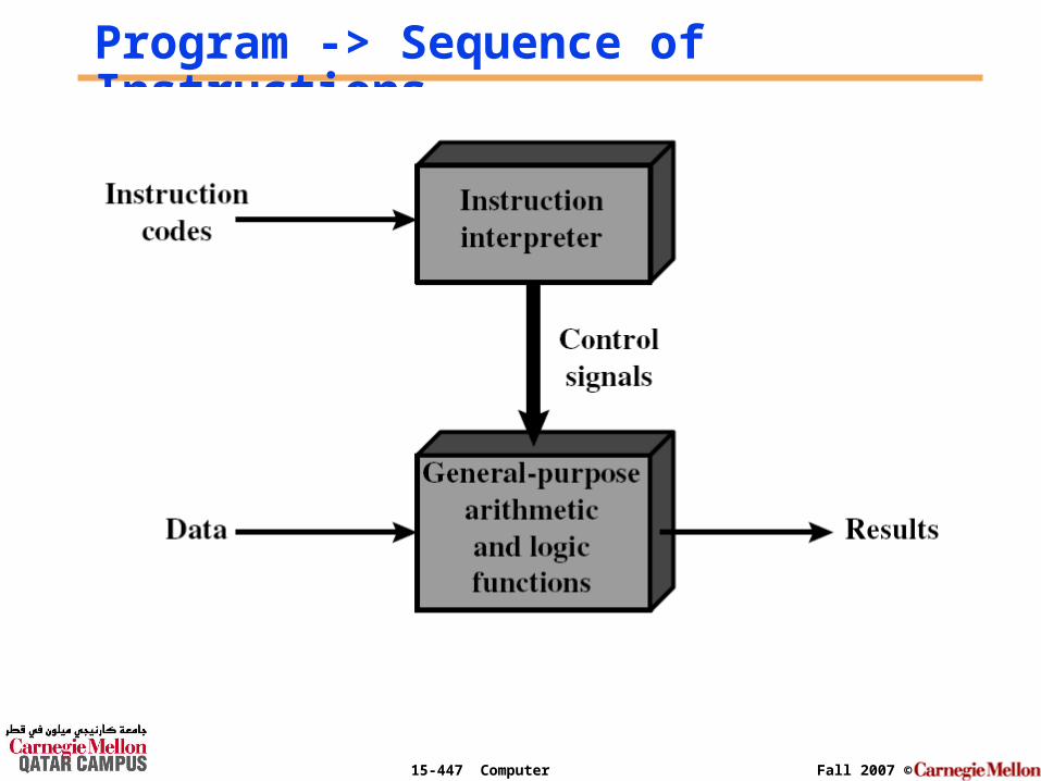
Program -> Sequence of Instructions
15-447 Computer Architecture Fall 2007 ©
Function of Control Unit°For each operation a unique code is provided
• e.g. ADD, MOVE
°A hardware segment accepts the code and issues the control signals
°We have a computer!

15-447 Computer Architecture Fall 2007 ©
Computer Components: Top Level View
15-447 Computer Architecture Fall 2007 ©
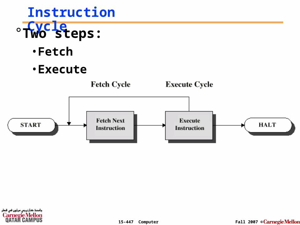
Instruction Cycle°Two steps:• Fetch
• Execute
15-447 Computer Architecture Fall 2007 ©
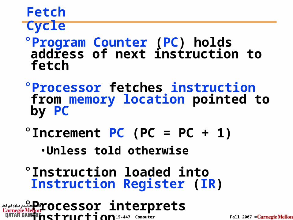
Fetch Cycle°Program Counter (PC) holds address of next instruction to fetch
°Processor fetches instruction from memory location pointed to by PC
° Increment PC (PC = PC + 1)• Unless told otherwise
° Instruction loaded into Instruction Register (IR)
°Processor interprets instruction
15-447 Computer Architecture Fall 2007 ©
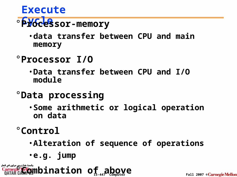
Execute Cycle° Processor-memory
• data transfer between CPU and main memory
° Processor I/O• Data transfer between CPU and I/O module
° Data processing• Some arithmetic or logical operation on data
° Control• Alteration of sequence of operations
• e.g. jump
° Combination of above
15-447 Computer Architecture Fall 2007 ©
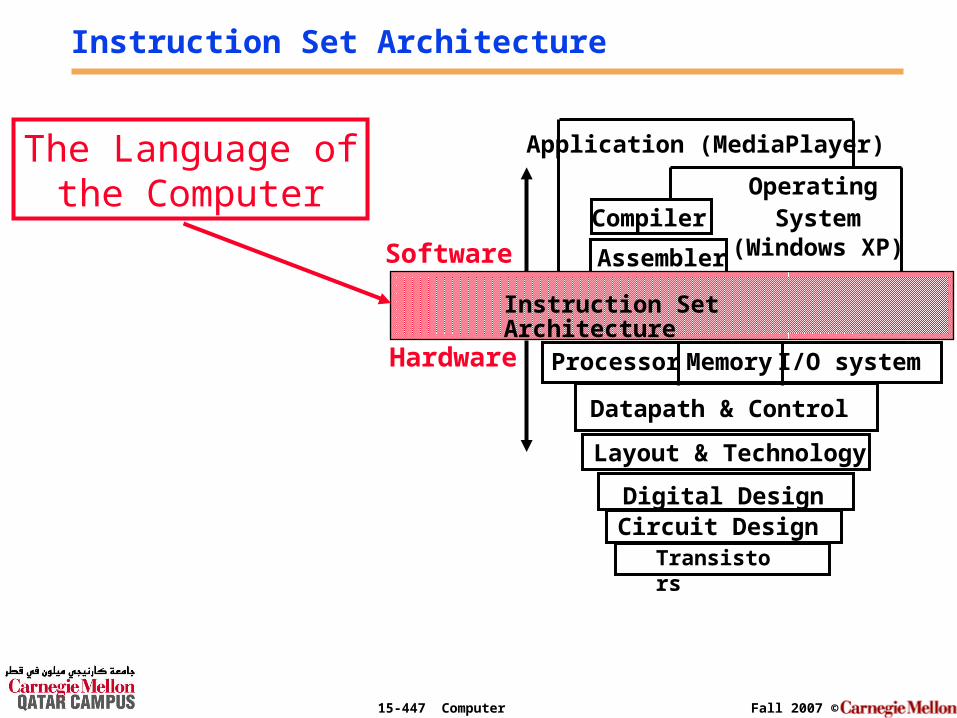
Instruction Set Architecture
I/O systemProcessor
CompilerOperating
System(Windows XP)
Application (MediaPlayer)
Digital DesignCircuit Design
Instruction Set Architecture
Datapath & Control
Transistors
MemoryHardware
Software Assembler
Layout & Technology
The Language ofthe Computer
15-447 Computer Architecture Fall 2007 ©
Chapter objectives
°The goal of this lecture is to discuss an instruction set (a simple one), showing both how instructions are represented in hardware & the relationship between high-level programming languages (for example C-language which you know) and this more primitive one.
°Next time: the different addressing modes.
15-447 Computer Architecture Fall 2007 ©
°By learning how to represent instructions, you will also discover the secret of computing: the stored-program concept.
Chapter objectives (2)
15-447 Computer Architecture Fall 2007 ©
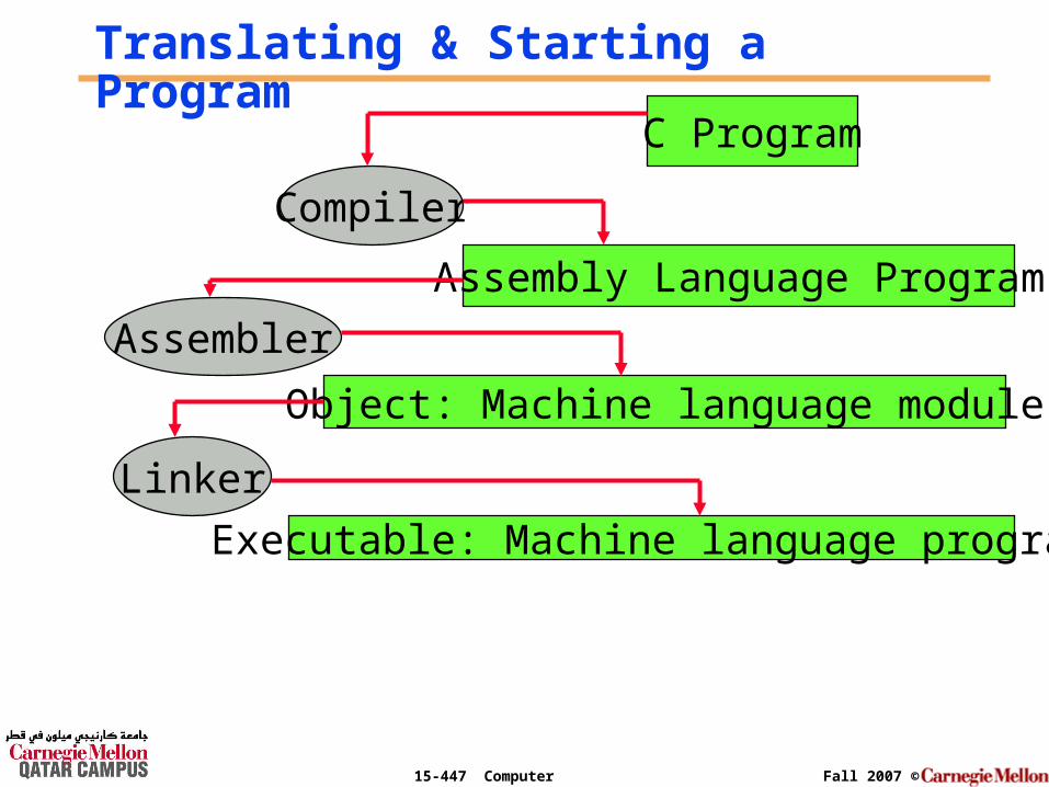
Translating & Starting a Program
C Program
Compiler
Assembly Language Program
Assembler
Object: Machine language module
Linker
Executable: Machine language program
15-447 Computer Architecture Fall 2007 ©
Translating & Optimizing a Program: The Compiler
The Compiler transforms the C program into an assembly language program, a symbolic form of what the machine understands.
15-447 Computer Architecture Fall 2007 ©
Translating a Program: The Assembler
The Assembler transforms the
Assembly program into a machine language module.
15-447 Computer Architecture Fall 2007 ©
Stitching a Program: The Linker
The linker or link editor takes all the independently assembled machine language programs and “stitches” them together.
There are three steps for the linker: 1) Place code and data modules symbolically
in memory2) Determine the addresses of data and instruction labels3) Patch both the internal and external references

15-447 Computer Architecture Fall 2007 ©
What Happens in Hardware?
CPU Memory
Instructions
Data
15-447 Computer Architecture Fall 2007 ©
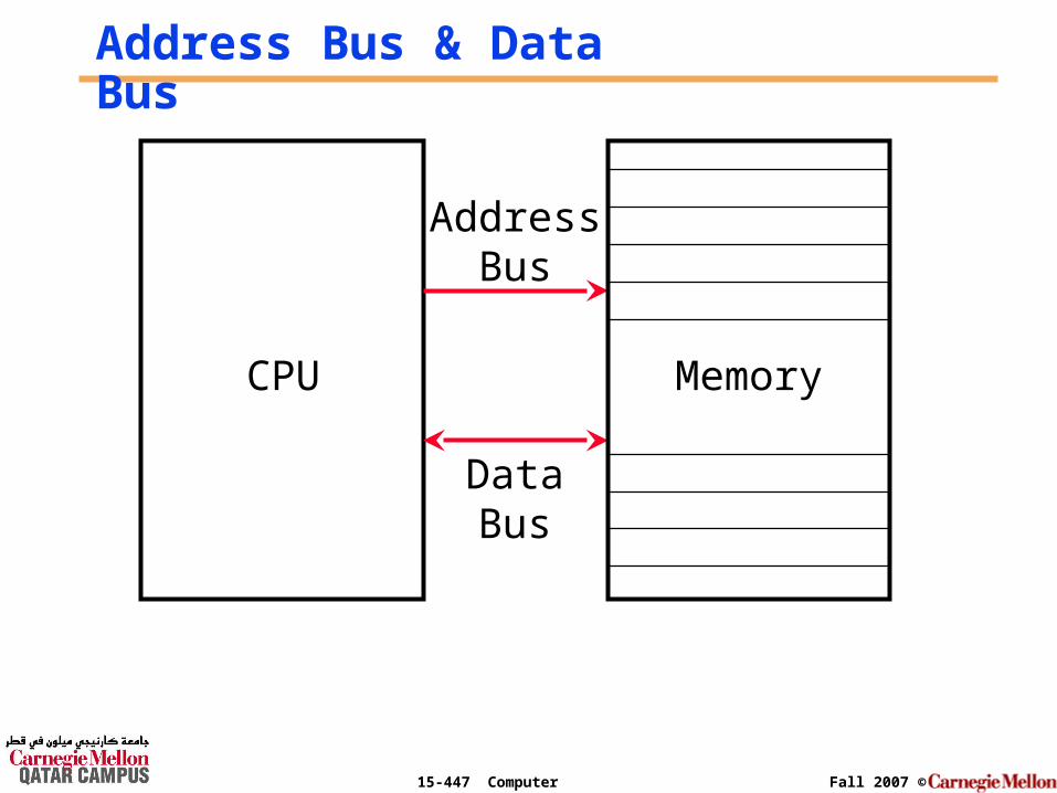
Address Bus & Data Bus
DataBus
AddressBus
CPU Memory
15-447 Computer Architecture Fall 2007 ©
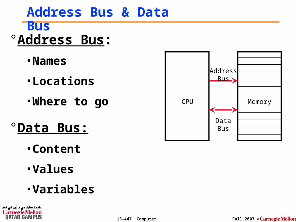
Address Bus & Data Bus
DataBus
AddressBus
CPU Memory
°Address Bus:
• Names
• Locations
• Where to go
°Data Bus:
• Content
• Values
• Variables

15-447 Computer Architecture Fall 2007 ©
Memory Addressing
15-447 Computer Architecture Fall 2007 ©
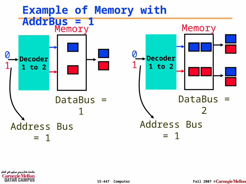
Example of Memory with AddrBus = 1
Decoder1 to 2
Memory
01
DataBus = 1
Decoder1 to 2
Memory
01
DataBus = 2
Address Bus = 1 Address Bus = 1
15-447 Computer Architecture Fall 2007 ©
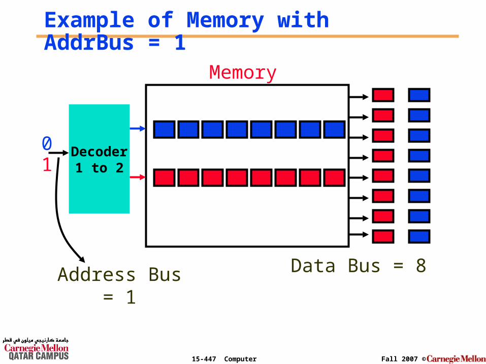
Example of Memory with AddrBus = 1
Decoder1 to 2
Memory
01
Address Bus = 1 Data Bus = 8
15-447 Computer Architecture Fall 2007 ©
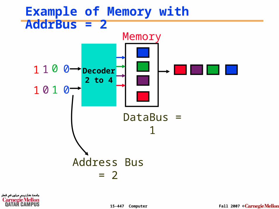
Example of Memory with AddrBus = 2
Decoder2 to 4
Memory
0
1
DataBus = 1
0
0
0
1
1
1
Address Bus = 2
15-447 Computer Architecture Fall 2007 ©
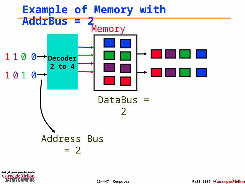
Decoder2 to 4
Memory
0
1
DataBus = 2
0
0
0
1
1
1
Example of Memory with AddrBus = 2
Address Bus = 2
15-447 Computer Architecture Fall 2007 ©
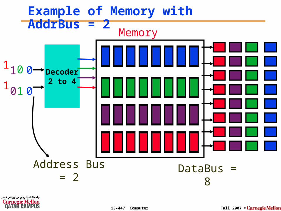
Decoder2 to 4
Memory
0
1
DataBus = 8
0
0
0
11
1
Example of Memory with AddrBus = 2
Address Bus = 2
15-447 Computer Architecture Fall 2007 ©
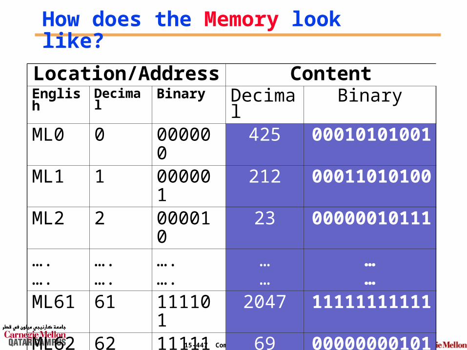
How does the Memory look like?
Location/Address ContentEnglish Decimal Binary Decimal BinaryML0 0 000000 425 00010101001ML1 1 000001 212 00011010100ML2 2 000010 23 00000010111….….
…. ….
….….
……
……
ML61 61 111101 2047 11111111111ML62 62 111110 69 00000000101ML63 63 111111 1559 11000010111
15-447 Computer Architecture Fall 2007 ©
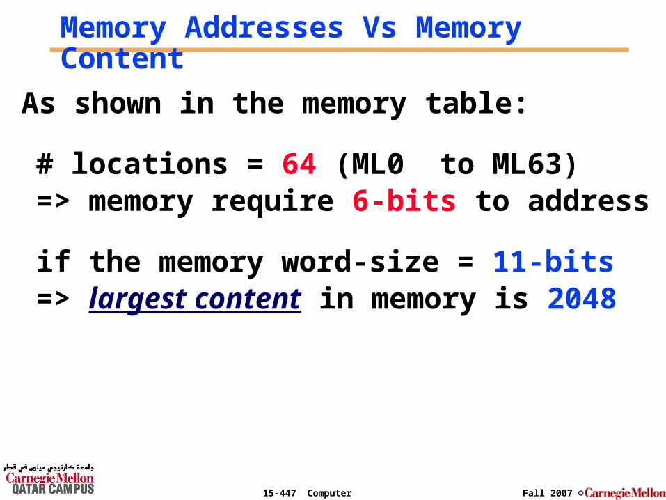
Memory Addresses Vs Memory Content
As shown in the memory table:
# locations = 64 (ML0 to ML63)=> memory require 6-bits to address
if the memory word-size = 11-bits => largest content in memory is 2048
15-447 Computer Architecture Fall 2007 ©
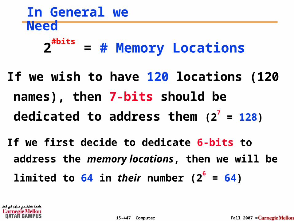
In General we Need
2#bits
= # Memory Locations
If we wish to have 120 locations (120 names),
then 7-bits should be dedicated to address
them (27 = 128)
If we first decide to dedicate 6-bits to address the memory
locations, then we will be limited to 64 in their number
(26 = 64)
15-447 Computer Architecture Fall 2007 ©
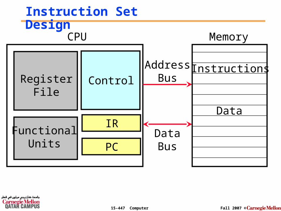
Instruction Set Design
DataBus
AddressBus
CPU Memory
ControlRegisterFile
FunctionalUnits
IR
PC
Instructions
Data

15-447 Computer Architecture Fall 2007 ©
What is an instruction set?
° The complete collection of instructions that are understood by a CPU
° Machine Code
° Binary
° Usually represented by assembly codes

15-447 Computer Architecture Fall 2007 ©
Elements of an Instruction
° Operation code (Op code)• Do this operation
° Source Operand reference• To this to this value
° Result Operand reference• Put the answer here

15-447 Computer Architecture Fall 2007 ©
Operation Code (page 342)
° Operation code(Opcode)
• Do this operation
Name Mnemonic
Addition ADD
Subtraction SUB
… …
Multiply MULT

15-447 Computer Architecture Fall 2007 ©
Processor Operations:
Data processing
Data storage
Data movement
Program flow
control
°Add
°Sub
°Load
°Store
°Read
°Write
°GoTo
°BranchIfIn total, the # of instructions desired is 8, and these require 3-bits for controlling.

15-447 Computer Architecture Fall 2007 ©
Registers & How Big?
° CPU must have some working space (temporary storage)
° Number of Registers varies between processor designs
° Large enough to hold full address
° Large enough to hold full data word
15-447 Computer Architecture Fall 2007 ©
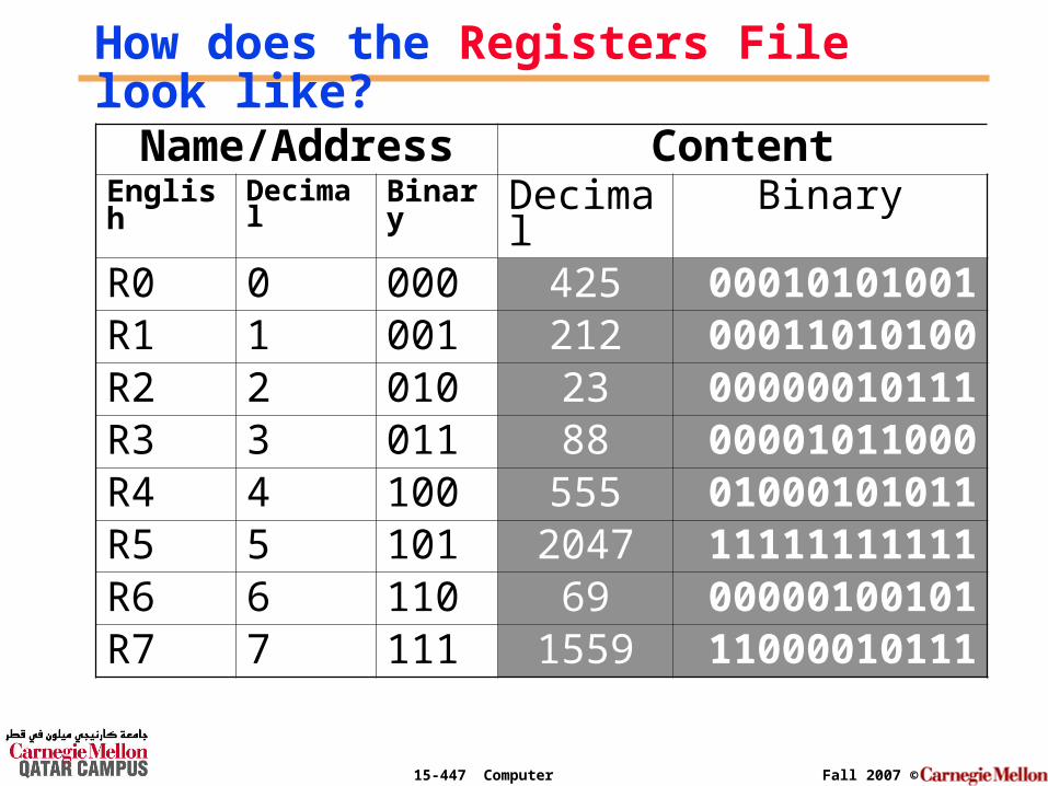
How does the Registers File look like?
Name/Address ContentEnglish Decimal Binary Decimal BinaryR0 0 000 425 00010101001R1 1 001 212 00011010100R2 2 010 23 00000010111R3 3 011 88 00001011000R4 4 100 555 01000101011R5 5 101 2047 11111111111R6 6 110 69 00000100101R7 7 111 1559 11000010111

15-447 Computer Architecture Fall 2007 ©
Register Address Vs Register Content
As shown in the register file:
# registers = 8 (R0 to R7)=> registers require 3-bits to address
if the register size = 11-bits=> largest content in registers is 2047
15-447 Computer Architecture Fall 2007 ©
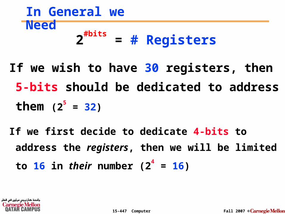
In General we Need
2#bits
= # Registers
If we wish to have 30 registers, then 5-bits
should be dedicated to address them (25 = 32)
If we first decide to dedicate 4-bits to address the
registers, then we will be limited to 16 in their number (24
= 16)

15-447 Computer Architecture Fall 2007 ©
Instruction Design
Data processin
g
Data storage
Data movement
Program flow control
Sub 000
Load 010
Read 100
GoTo 110
Add 001
Store 011
Write
101
BranchIf
111
I want this operation to make the additionof two registers & place the result in a third one
Example: Add R1, R2, R3 ; R1 = R2 + R3
15-447 Computer Architecture Fall 2007 ©
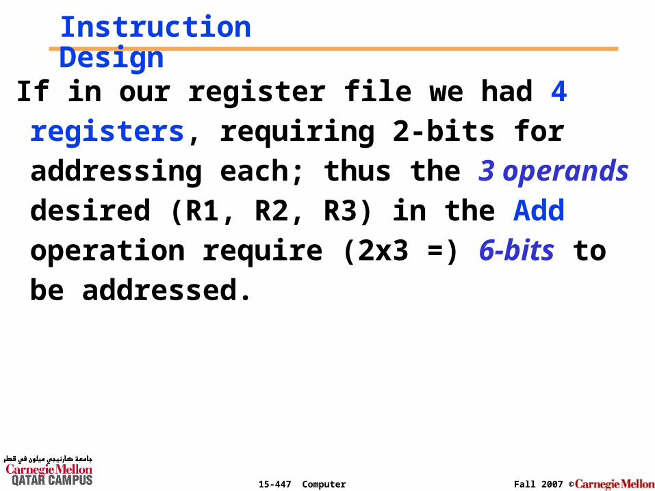
Instruction Design
If in our register file we had 4 registers, requiring 2-bits for addressing each; thus the 3 operands desired (R1, R2, R3) in the Add operation require (2x3 =) 6-bits to be addressed.

15-447 Computer Architecture Fall 2007 ©
Instruction Design: Add R0, R4, R11Add R1, R2, R3
001 01 10 11
OpCode Destination
Register
Source
Register
Source
Register
3-bits 2-bits 2-bits 2-bits
9-bits Instruction
15-447 Computer Architecture Fall 2007 ©
Add R1, R2, R3 ;(= 001011011)
Register File
FunctionalUnits
I.R.
P.C.
001011011
01
23
4
5
67
2
2001011011 001011011
... 3
CPU Memory
What happens inside the CPU?

15-447 Computer Architecture Fall 2007 ©
I.R.
P.C.3
001011011
Add R1, R2, R3 ;(= 001011011)
+
010101010
001010101
... R1
R2
R3
010101010 001010101
011111111 NextInstruction
4
CPU

15-447 Computer Architecture Fall 2007 ©
Hypothetical Machine
Consider the following hypothetical machine:
# registers = 16 {R0 to R15} require 4-bits to address them (24 = 16)
# memory locations = 256 {M0 to M255} require 8-bits to address them (28 = 256)
15-447 Computer Architecture Fall 2007 ©
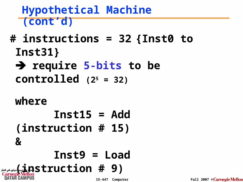
Hypothetical Machine (cont’d)
# instructions = 32 {Inst0 to Inst31} require 5-bits to be controlled (25 = 32)
where Inst15 = Add (instruction # 15)
& Inst9 = Load (instruction # 9)

15-447 Computer Architecture Fall 2007 ©
Example 1: Add R0, R4, R11
Add R0, R4, R11 ; R0 = R4 + R11
01111 0000 0100 1011
And to make it simpler to read and use we will use the Hex notation
F 0 4 B
And the output of the assembler would simply be the following machine code: F04B
15-447 Computer Architecture Fall 2007 ©
The instruction
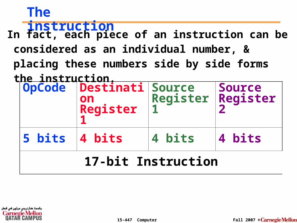
In fact, each piece of an instruction can be considered as an individual number, & placing these numbers side by side forms the instruction.
OpCode Destination Register 1
Source Register 1
Source Register 2
5 bits 4 bits 4 bits 4 bits
17-bit Instruction
15-447 Computer Architecture Fall 2007 ©
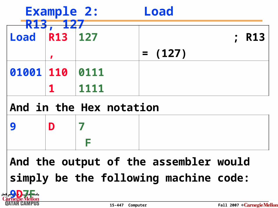
Example 2: Load R13, 127
Load R13, 127 ; R13 = (127)
01001 1101 0111 1111
And in the Hex notation
9 D 7 F
And the output of the assembler would simply be
the following machine code: 9D7F
15-447 Computer Architecture Fall 2007 ©
The instruction
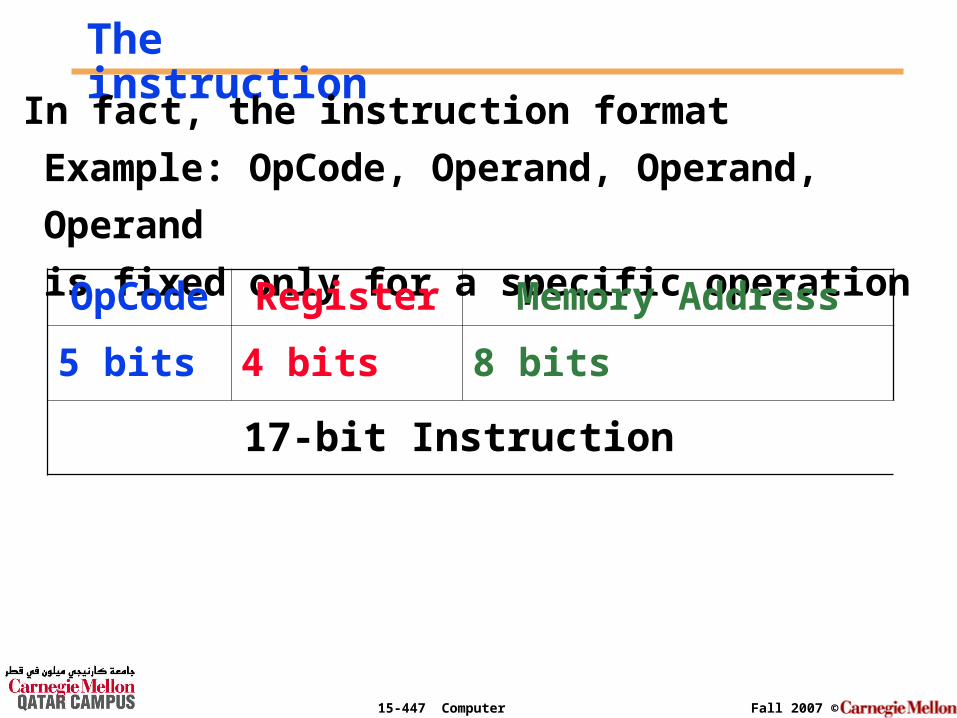
In fact, the instruction format
Example: OpCode, Operand, Operand, Operand
is fixed only for a specific operation
OpCode Register Memory Address
5 bits 4 bits 8 bits
17-bit Instruction

15-447 Computer Architecture Fall 2007 ©
Note
° When the OpCode consist of a memory R/W, the
operand, Source Register 1 & 2 are combined to
form the address field of the instruction.
° When the OpCode consist of an immediate
instruction, the operand, Source Register 1 & 2
are combined to form the constant whenever that
is required.

15-447 Computer Architecture Fall 2007 ©
The Instruction
°OpCode: basic operation of the instruction
°Destination Register: register where the result of the operations will be loaded
°Source Register 1 & 2: registers where the data will be operated on
15-447 Computer Architecture Fall 2007 ©
Instruction size = data word size
As you can see from counting the number of bits, this hypothetical machine instruction takes exactly 17-bits which should be the same size as a data word.

15-447 Computer Architecture Fall 2007 ©
Design by Starting with the Instruction SizeWe would like to design a machine with:
• Instruction size = 8 bits
• Instruction number = 8
1. No Operation2. Add3. Sub4. Branch5. Load6. Store7. Increment8. Decrement
3-bits of the instruction word will be reserved to control the 8 desired instructions
x x x
15-447 Computer Architecture Fall 2007 ©
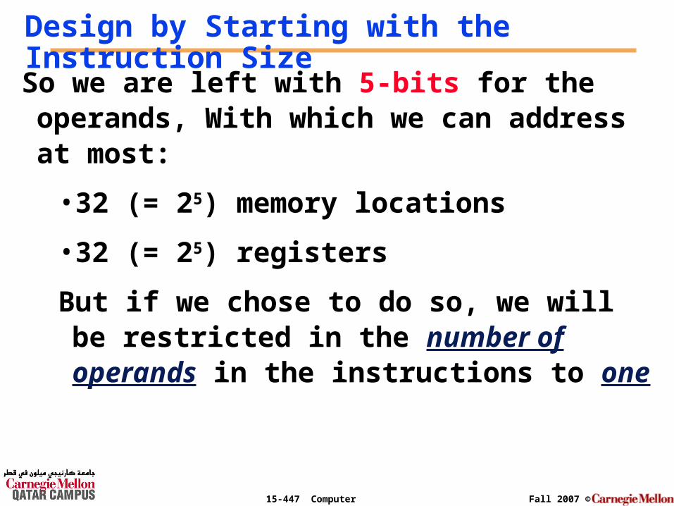
So we are left with 5-bits for the operands, With which we can address at most:
• 32 (= 25) memory locations
• 32 (= 25) registers
But if we chose to do so, we will be restricted in the number of operands in the instructions to one
Design by Starting with the Instruction Size

15-447 Computer Architecture Fall 2007 ©
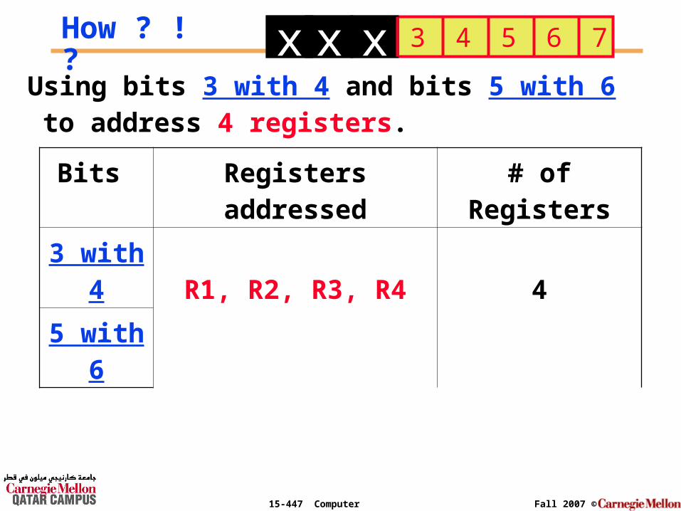
On the other hand if we wish to have instructions with 2 explicit operands; that is still possible with the 5-bits left.
Design by Starting with the Instruction Size
x x x
How ? ! ?
15-447 Computer Architecture Fall 2007 ©
How ? ! ?
Using bits 3 with 4 and bits 5 with 6 to address 4 registers.
x x x 3 4 5 6 7
Bits Registers addressed # of Registers
3 with 4R1, R2, R3, R4 45 with 6
15-447 Computer Architecture Fall 2007 ©
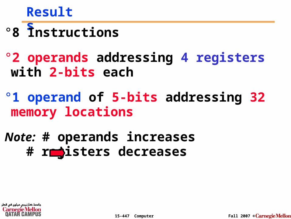
Results°8 Instructions
°2 operands addressing 4 registers with 2-bits each
°1 operand of 5-bits addressing 32 memory locations
Note: # operands increases # registers decreases
15-447 Computer Architecture Fall 2007 ©
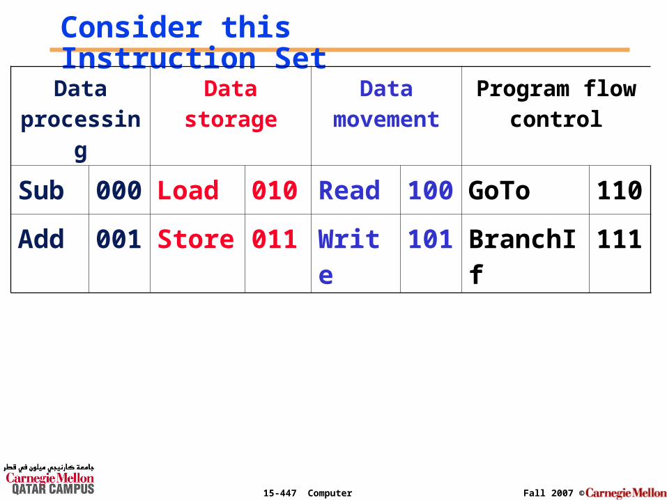
Consider this Instruction Set
Data processin
g
Data storage
Data movement
Program flow control
Sub 000
Load 010
Read 100
GoTo 110
Add 001
Store 011
Write
101
BranchIf
111

15-447 Computer Architecture Fall 2007 ©
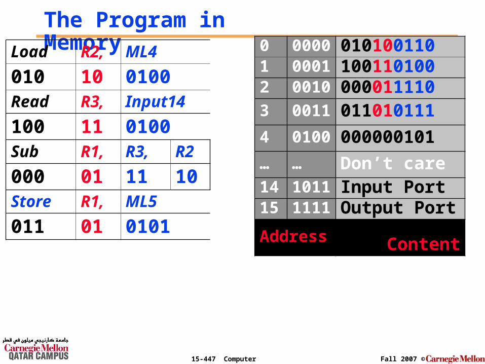
Execution of a simple programThe following program was loaded in memory starting from memory location 0.
0000 Load R2, ML4 ; R2 = (ML4) = 5 = 1012
0001 Read R3, Input14 ; R3 = input device 14 = 7
0010 Sub R1, R3, R2 ; R1 = R3 – R2 = 7 – 5 = 2
0011 Store R1, ML5 ; store (R1) = 2 in ML5
15-447 Computer Architecture Fall 2007 ©
The Program in MemoryLoad R2, ML4
010 10 0100Read R3, Input14
100 11 0100Sub R1, R3, R2
000 01 11 10Store R1, ML5
011 01 0101
0 0000 0101001101 0001 1001101002 0010 0000111103 0011 011010111
4 0100 000000101
… … Don’t care14 1011 Input Port15 1111 Output PortAddress Content
15-447 Computer Architecture Fall 2007 ©
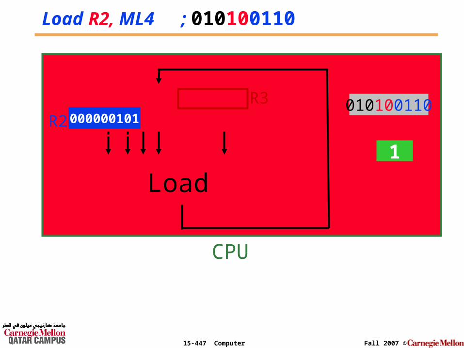
I.R.
P.C.
010100110
Load R2, ML4 ; 010100110
Load
... R1
R2
R3000000101
0
CPU
1
15-447 Computer Architecture Fall 2007 ©
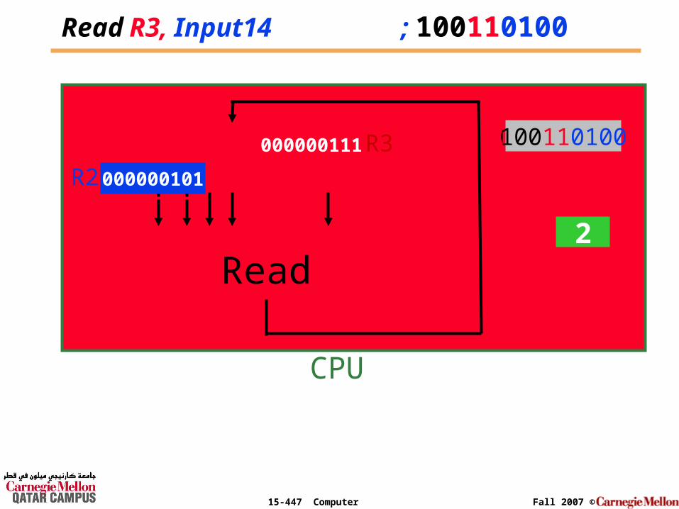
ReadR3, Input14 ; 100110100
Read
... R1
R2
R3
000000101
CPU
12
010100110100110100000000111

15-447 Computer Architecture Fall 2007 ©
Sub R1, R3, R2 ; 000011110
Sub
... R1
R2
R3
000000101
CPU
23
100110101
000000111000000101
000000010 000000111 000011110
15-447 Computer Architecture Fall 2007 ©
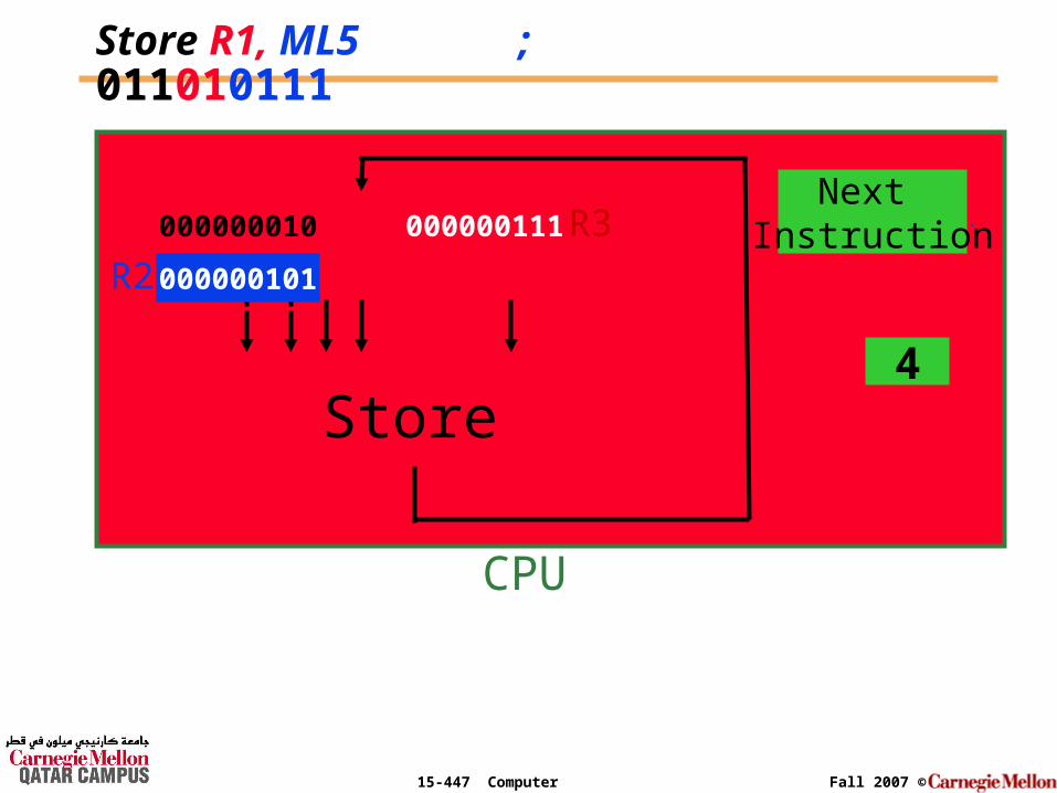
Store R1, ML5 ; 011010111
Don’t Care
... R1
R2
R3
000000101
CPU
34
011010111Next
Instruction000000010 000000111
Store

15-447 Computer Architecture Fall 2007 ©
BeforeProgram
Execution
In the Memory
0 0000 0101001101 0001 1001101002 0010 0000111103 0011 0110101114 0100 0000001015 0101 Don’t care… … Don’t care14 1011 Input Port15 1111 Output PortAddress Content
000000010
AfterProgram
Execution