15 intake and exhaust - nogas.org · 15-2 intake and exhaust - general information general...
TRANSCRIPT

15-1
INTAKE AND EXHAUST
CONTENTS E15AA
GENERAL INFORMATION 2
SPECIFICATIONS 3
General Specifications 3
Service Specifications 4
Torque Specifications 4
Sealant and Adhesive 5
TROUBLESHOOTING 5
AIRCLEANER 6
INTAKE MANIFOLD 12
EXHAUST MANIFOLD 18
INTAKE AND EXHAUST MANIFOLD 22
EXHAUST PIPES AND MUFFLERS 24
© Mitsubishi Motors Corporation Jun. 1994 PWWE8608-D REVISED

15-2 INTAKE A N D EXHAUST - General Information
GENERAL INFORMATION E15BAAG
All models are equipped with dry type air cleaners. A resonator is installed on all models except 4G32 and 4G33. to prevent resonance in induction system. An air flow sensor and intake air temperature sensor are installed for MPI air cleaner. The exhaust system is divided into the front exhaust pipe and main muffler, between which a catalytic converter is installed on FBC and MPI vehicles.
Petrol-powered vehicles without M.P.I. (4G63, G63B)
Air duct B
Air duct A
Air intake hose
Air horn
Air duct C
Air cleaner
Petrol-powered vehicles w i t h M.P.I.
(4G64, G64B)
Air duct B
Resonator
Resonator Air horn
Air duct A
Air duct C
Air cleaner
Air intake hose
31N062 05G0022
Diesel-powered vehicles
Resonator Air duct B
Air intake hose Air duct A
Air duct C
Air cleaner
D1N013
© Mitsubishi Motors Corporation NOV. B6 PWWE8608
INTAKE AND EXHAUST-Specifications 1 5 - 3
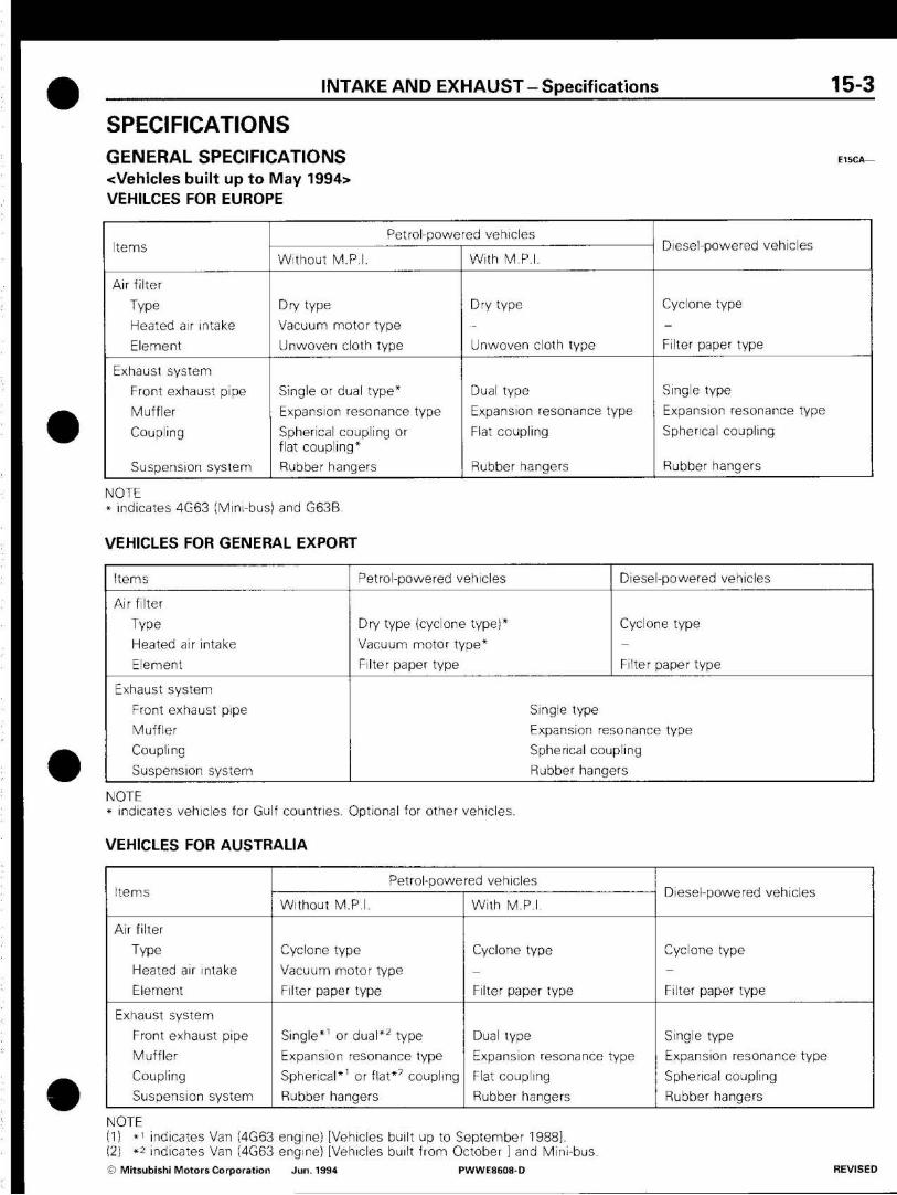
SPECIFICATIONS GENERAL SPECIFICATIONS E 1 5 C A _
<Vehicles built up to May 1994> VEHILCES FOR EUROPE
Items
Air filter
Type
Heated air intake
Element
Exhaust system
Front exhaust pipe
Muffler
Coupling
Suspension system
Petrol-powered vehicles
Without M.P.I.
Dry type
Vacuum motor type
Unwoven cloth type
Single or dual type*
Expansion resonance type
Spherical coupling or flat coupling*
Rubber hangers
With M.P.I.
Dry type
Unwoven cloth type
Dual type
Expansion resonance type
Flat coupling
Rubber hangers
Diesel-powered vehicles
Cyclone type
Filter paper type
Single type
Expansion resonance type
Spherical coupling
Rubber hangers
NOTE * indicates 4G63 (Mini-bus) and G63B.
VEHICLES FOR GENERAL EXPORT
Items
Air filter
Type
Heated air intake
Element
Exhaust system
Front exhaust pipe
Muffler
Coupling
Suspension system
Petrol-powered vehicles
Dry type (cyclone type)*
Vacuum motor type*
Filter paper type
Diesel-powered vehicles
Cyclone type
Filter paper type
Single type
Expansion resonance type
Spherical coupling
Rubber hangers
NOTE * indicates vehicles for Gulf countries. Optional for other vehicles.
VEHICLES FOR AUSTRALIA
Items
Air filter
Type
Heated air intake
Element
Exhaust system
Front exhaust pipe
Muffler
Coupling
Suspension system
Petrol-powered vehicles
Without M.P.I.
Cyclone type
Vacuum motor type
Filter paper type
Single*' or dual*2 type
Expansion resonance type
Spherical*1 or flat*' coupling
Rubber hangers
With M.PL
Cyclone type
Filter paper type
Dual type
Expansion resonance type
Flat coupling
Rubber hangers
Diesel-powered vehicles
Cyclone type
Filter paper type
Single type
Expansion resonance type
Spherical coupling
Rubber hangers
NOTE (1) *1 indicates Van (4G63 engine) [Vehicles built up to September 1988]. (2) *2 indicates Van (4G63 engine) [Vehicles built from October ] and Mini-bus.
© Mitsubishi Motors Corporation Jun. 1994 PWWE8608-D REVISED
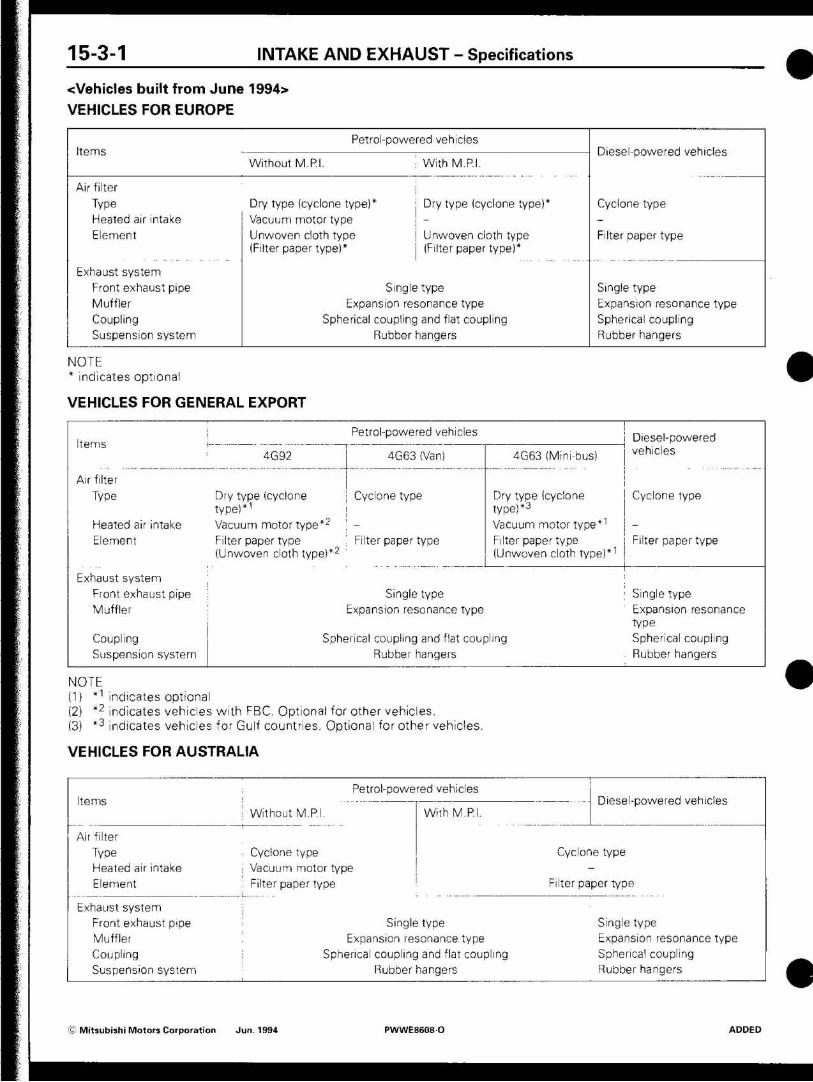
1 5 - 3 - 1 INTAKE AND EXHAUST - Specifications
<Vehicles built from June 1994>
VEHICLES FOR EUROPE
Items
Air filter
Type
Heated air intake
Element
Exhaust system
Front exhaust pipe
Muffler
Coupling
Suspension system
Petrol-powered vehicles
Without M.P.I. ! With M.P.I.
Dry type (cyclone type)* Dry type (cyclone type)*
Vacuum motor type \ -
Unwoven cloth type | Unwoven cloth type
(Filter paper type)* (Filter paper type)*
Single type
Expansion resonance type
Spherical coupling and flat coupling
Rubber hangers
Diesel-powered vehicles
Cyclone type
-Filter paper type
Single type
Expansion resonance type
Spherical coupling
Rubber hangers
NOTE * indicates optional
VEHICLES FOR GENERAL EXPORT
Items
Air filter
Type
Heated air intake
Element
Exhaust system
Front exhaust pipe
Muffler
Coupling
Suspension system
Petrol-powered vehicles
4G92 4G63 (Van)
Dry type (cyclone Cyclone type
type)*1
Vacuum motor type* 2 -
Filter paper type Filter paper type
(Unwoven cloth type)*2
4GB3 (Mini-bus)
Dry type (cyclone
type)*3
Vacuum motor type*1
Filter paper type
(Unwoven cloth type)*1
Single type
Expansion resonance type
Spherical coupling and flat coupling
Rubber hangers
Diesel-powered
vehicles
Cyclone type
-Filter paper type
Single type
Expansion resonance
type
Spherical coupling
Rubber hangers
NOTE (1) *1 indicates optional (2) *2 indicates vehicles with FBC. Optional for other vehicles. (3) *3 indicates vehicles for Gulf countries. Optional for other vehicles.
VEHICLES FOR AUSTRALIA
Items
Air filter
Type
Heated air intake
Element
Exhaust system
Front exhaust pipe
Muffler
Coupling
Suspension system
; Petrol-powered vehicles
! Without M.PI.
. Cyclone type
; Vacuum motor type
With M.P.I.
; Filter paper type
Single type
Expansion resonance type
i Spherical coupling and flat coupling
Rubber hangers
Diesel-powered vehicles
Cyclone type
-Filter paper type
Single type
Expansion resonance type
Spherical coupling
Rubber hangers
- Mitsubishi Motors Corporation Jun. 1994 PWWE8608-O ADDED
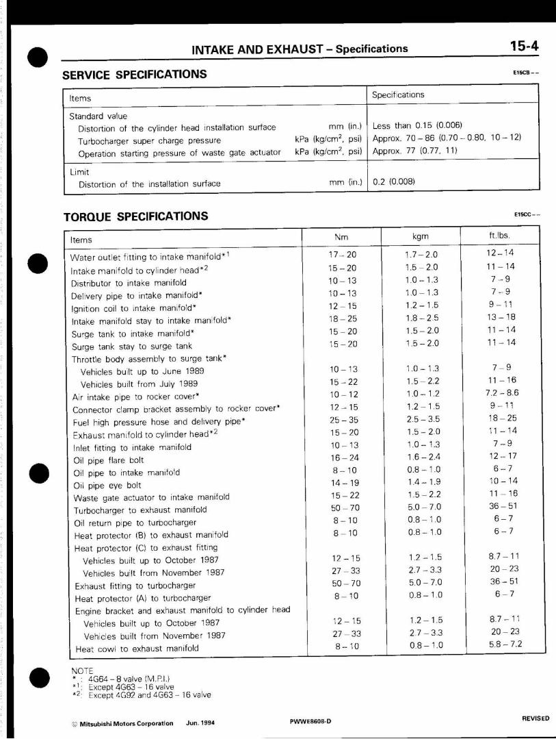
INTAKE AND EXHAUST - Specifications 15-4
SERVICE SPECIFICATIONS
Items
Standard value
Distortion of the cylinder head installation surface mm (in.)
Turbocharger super charge pressure kPa (kg/cm , psi)
Operation starting pressure of waste gate actuator kPa (kg/cm2, psi)
Limit
Distortion of the installation surface ntm (in.)
Specifications
Less than 0.15 (0.006)
Approx. 7 0 - 8 6 (0.70-0.80. 10-12)
Approx. 77 (0.77, 11)
0.2 (0.008)
TORQUE SPECIFICATIONS
Items
Water outlet fitting to intake manifold*1
Intake manifold to cylinder head*2
Distributor to intake manifold
Delivery pipe to intake manifold*
Ignition coil to intake manifold*
Intake manifold stay to intake manifold*
Surge tank to intake manifold*
Surge tank stay to surge tank
Throttle body assembly to surge tank*
Vehicles built up to June 1989
Vehicles built from July 1989
Air intake pipe to rocker cover*
Connector clamp bracket assembly to rocker cover*
Fuel high pressure hose and delivery pipe*
Exhaust manifold to cylinder head*2
Inlet fitting to intake manifold
Oil pipe flare bolt
Oil pipe to intake manifold
Oil pipe eye bolt
Waste gate actuator to intake manifold
Turbocharger to exhaust manifold
Oil return pipe to turbocharger
Heat protector (B) to exhaust manifold
Heat protector (C) to exhaust fitting
Vehicles built up to October 1987
Vehicles built from November 1987
Exhaust fitting to turbocharger
Heat protector (A) to turbocharger
Engine bracket and exhaust manifold to cylinder head
Vehicles built up to October 1987
Vehicles built from November 1987
Heat cowl to exhaust manifold
I
Nm
1 7 - 2 0
1 5 - 2 0
1 0 - 1 3
1 0 - 1 3
1 2 - 1 5
1 8 - 2 5
1 5 - 2 0
1 5 - 2 0
1 0 - 1 3
1 5 - 2 2
1 0 - 1 2
1 2 - 1 5
2 5 - 3 5
1 5 - 2 0
1 0 - 1 3
1 6 - 2 4
8 - 1 0
1 4 - 1 9
1 5 - 2 2
5 0 - 7 0
8 - 1 0
8 - 1 0
1 2 - 1 5
2 7 - 3 3
5 0 - 7 0
8 - 1 0
1 2 - 1 5
2 7 - 3 3
8 - 1 0
kgm
1.7-2.0
1.5-2.0
1.0-1.3
1.0-1.3
1.2-1.5
1.8-2.5
1.5-2.0
1.5 - 2.0
1.0-1.3
1.5-2.2
1.0-1.2
1.2-1.5
2 .5-3 .5
1.5-2.0
1.0-1.3
1.6-2.4
0.8 - 1.0
1.4-1.9
1.5-2.2
5 .0-7 .0
0 .8-1 .0
0 .8-1 .0
1.2-1.5
2 .7-3 .3
5.0-7.0
0 .8-1 .0
1.2-1.5
2 .7-3 .3
0 .8-1 .0
ft.lbs.
12 -14
11 - 1 4
7 - 9
7 - 9
9 - 1 1
1 3 - 1 8
11 - 1 4
11 - 1 4
7 - 9
11 - 1 6
7 .2-8 .6
9 - 1 1
1 8 - 2 5
11 - 1 4
7 - 9
1 2 - 1 7
6 - 7
1 0 - 1 4
11 - 1 6
3 6 - 5 1
6 - 7
6 - 7
8 .7 -11
2 0 - 2 3
3 6 - 5 1
6 - 7
8 .7 -11
2 0 - 2 3
5.8-7.2
NOTE * : 4G64-8 valve (M.P.I.) *1: Except 4G63-16 valve *2: Except 4G92 and 4G63 - 16 valve
© Mitsubishi Motors Corporation Jun. 1994 PWWE8608-D

15 -4 -1 INTAKE AND EXHAUST - Specifications
Items
Air pipe assembly to exhaust manifold
Air pipe assembly to exhaust manifold*
Air pipe assembly to air pipe stay
Air pipe stay to exhaust manifold
Vehicles built up to October 1987
Vehicles built from November 1987
Reed valve to reed valve stay
Oxygen sensor to exhaust manifold
Front exhaust pipe to exhaust manifold
Single exhaust pipe (petrol-powered vehicles)*1
Single exhaust pipe (diesel-powered vehicles)
Dual exhaust pipe
Front exhaust pipe bracket
Front exhaust pipe to under catalytic converter*2
Under catalytic converter to main muffler*2
Front exhaust pipe to main muffler
Fuel vapor separator and vapor hose and
pipe assembly to intake manifold
Thermo valve to intake manifold (upper)
Engine coolant temperature sensor to intake manifold
Engine coolant temperature gauge unit to intake manifold
EGR valve to intake manifold
4G92
4G63, 4G64
EGR valve to inlet fitting
Intake manifold stay
4G92
4G63, 4G64
Vacuum pipe assembly to intake manifold
Thermo valve to intake manifold (lower)
Single joint type
Except single joint type
Kick-down cable bracket to intake manifold
Intake manifold to cylinder head*3
Water outlet fitting to cylinder head*4
Heat protector to exhaust manifold
Secondary air pipe
Reed valve side
Exhaust manifold side
Nm
20-30
70-100
10-13
12-15
27-33
10-13
40 -50
25-35
30-40
40-55
20-30
50-70
30-40
20 -30
19-28
20-35
20-40
10-12
17-22
17-26
15-20
27-34
12-15
8-12
20-50
20-40
12-15
17-22
17-22
12-15
50-60
70-100
kgm
2.0-3.0
7.0-10.0
1.0-1.3
1.2-1.5
2.7-3.3
1.0-1.3
4.0-5.0
2.5-3.5
3.0-4.0
4.0-5.5
2.0-3.0
5.0-7.0
3.0-4.0
2.0-3.0
1.9-2.8
2.0-3.5
2.0-4.0
1.0-1.2
1.7-2.2
1.7-2.6
1.5-2.0
2.7-3.4
1.2-1.5
0.8-1.2
2.0-5.0
2.0-4.0
1.2-1.5
1.7-2.2
1.7-2.2
1.2-1.5
5.0-6.0 j
7.0-10.0 i
ft.lbs.
18-22
51-72
7.2-9.4
8.7-11
20-23
7.2-9.4
29-36
18-25
22 -29
29 -40
14-22
36 -50
22-29
14-22
14-20
14-25
14-29
7 -9
12-16
12-19
11-14
20-25
9-11
5.8-8.9
14-36
14-29
9-11
12-16
12-16
9-11
36-43
51-72
NOTE *: G63B *1: Vehicles with spherical coupling exhaust pipe *2: Except 4G92 (Hong Kong) *3; 4G92, 4G63 and 4G64 - 16 valve *4: 4G63 and 4G64 - 16 valve
X Mitsubishi Motors Corporation Jun. 1994 PWWE8608-O ADDED

INTAKE AND EXHAUST - Specifications/Troubleshooting 15-5
Items
Exhaust manifold attaching nut A
4G92
4G63 and 4 G 6 4 - 1 6 valve
Exhaust manifold attaching nut B
Inlet fitting to intake manifold
EGR pipe
Water pipe to turbocharger
Front exhaust pipe to exhaust manifold*1
Front exhaust pipe to under catalytic converter*2
Under catalytic converter to main muffler*2
Nm
15-20
25-30
27-33
10-13
15-20
34-49
40 -60
30 -40
50-70
kgm
1.5-2.0
2.5-3.0
2.7-3.3
1.0-1.3
1.5-2.0
3.5-5.0
4.0-6.0
3.0-4.0
5.0-7.0
ft.lbs.
11-14
18-22
20 -24
7 - 9
11-14
25-36
29-43
22-29
36 -50
NOTE *1: Vehicles with flat coupling exhaust pipe. *2: 4G92 (Hong Kong)
SEALANT AND ADHESIVE
Items
Engine coolant temperature gauge unit
Engine coolant temperature sensor
Thermo switch
Water outlet fitting
Specified sealant and adhesive
3M ATD Part No. 8660 or equivalent
3M Nut Locking Part No. 4171 or equivalent
Mitsubishi Genuine Parts No. MD970389 or
equivalent
Remarks
Semi drying sealant
Drying sealant
Semi drying sealant
TROUBLESHOOTING
Symptom
Exhaust gas leakage
Abnormal noise
Probable cause
Loose joints
Broken pipe or muffler
Broken separator in muffler
Broken rubber hangers
Interference of pipe or muffler with vehicle body
Broken pipe or muffler
Remedy
Retighten
Repair or replace
Replace
Replace
Correct
Repair or replace
Reference page
15-24. 25
15-24, 25
15-24, 25
15-24, 25
15-24, 25
15-24, 25
© Mitsubishi Motors Corporation Jun. 1994 PWWE8608-D REVISED
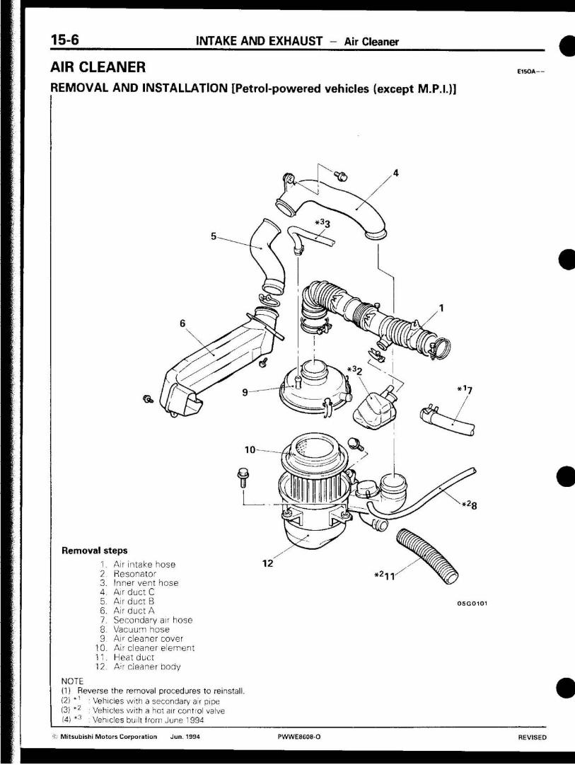
15-6 INTAKE AND EXHAUST - Air Cleaner
AIR CLEANER REMOVAL AND INSTALLATION [Petrol-powered vehicles (except M.P.I.)]
a
Removal steps
Air intake hose Resonator Inner vent hose Air duct C Air duct B Air duct A Secondary air hose Vacuum hose Air cleaner cover Air cleaner element Heat duct A r cleaner body
1. 2 3. 4. 5. 6. 7. 8. 9.
10. 11. 12
<£>
05G0101
NOTE (1) Reverse the removal procedures to reinstall. (2) * ' : Vehicles with a secondary air pipe (3) *z : Vehicles with a hot air control valve (4) *3 : Vehicles built from June 1994
r Mitsubishi Motors Corporation Jun. 1994 PWWE8608-O REVISED

INTAKE AND EXHAUST - Air Cleaner 15-7
Cover
Packing
05G0019
O1R0196
Vacuum motor
\ Negative pressure
Hot air control valve 51N003
INSPECTION ««*« • Check the air cleaner body, cover or packing for deformation,
corrosion or damage. • Check the air duct for damage.
Check the air cleaner element for clogging, contamination or damage. If element is slightly dogged, remove dust by blowing air from inside of element.
CHECKING OF THE HOT AIR CONTROL VALVE
Check to ensure that when negative pressure is applied to nipple of vacuum motor, valve operates as indicated by arrow.
© Mitsubishi Motors Corporation NOV. 86 PWWE8608
15-8 INTAKE AND EXHAUST - Air Cleaner
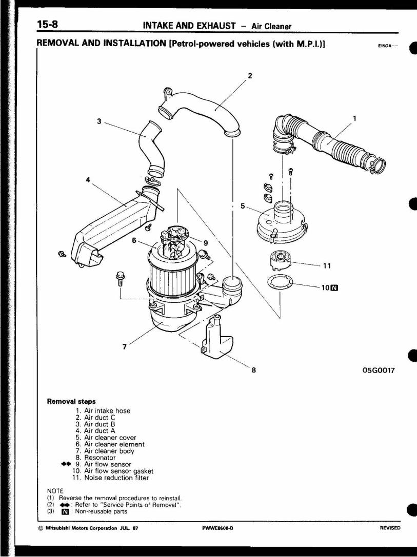
REMOVAL AND INSTALLATION [Petrol-powered vehicles (with M.P.I.)]
A~yi \
1
/
t ?
%
\ <§
h .-•-
» c
4 S"
y i
/
\ Ok Gk ? i i
Q,
10E1
A \
8 05G0017
Removal steps 1. Air intake hose 2. Air duct C 3. Air duct B 4. Air duct A 5. Air cleaner cover 6. Air cleaner element 7. Air cleaner body 8. Resonator
• • 9. Air flow sensor 10. Air flow sensor gasket 11. Noise reduction filter
NOTE (1) Reverse the removal procedures to reinstall. (2) mm Refer to "Service Points of Removal". (3) E I : Non-reusable parts
© Mtoubfahl Motors Corporation JUL. 87 PWWE860^B REVISED

INTAKE AND EXHAUST - Air Cleaner 15-9
SERVICE POINTS OF REMOVAL Et«*uc
9. REMOVAL OF AIR FLOW SENSOR
Remove air f low sensor from air cleaner case.
Caution Do not pull air f low sensor harness, because its grommet is fitted in air cleaner case.
Cover
Packing
z 05GO019
01R0196
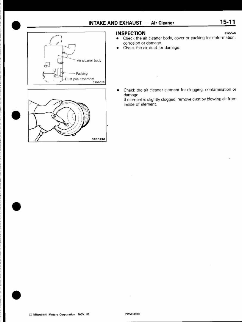
INSPECTION E,wcAG • Check the air cleaner body, cover or packing for deformation,
corrosion or damage. • Check the air duct for damage.
• Check the air cleaner element for dogging, contamination or damage. If element is slightly clogged, remove dust by blowing air from inside of element.
• Check the air cleaner for clogging, contamination or damage.
CHECKING OF THE AIR FLOW SENSOR
For inspection of air f low sensor, refer to GROUP 13 FUEL -Checking of the air f low sensor
© Mitsubishi Motors Corporation NOV. 86 PWWE8608

15-10 INTAKE AND EXHAUST - Air Cleaner
REMOVAL AND INSTALLATION (Diesel-powered vehicles) E1SOA
<jk
m
Removal steps 1. 2.
' 3. 4. 5. 6. 7. 8.
Air intake hose Air duct C Air duct B Air duct A Air cleaner assembly Dust pan assembly Wing bolt Air cleaner element
NOTE Reverse the removal procedures to reinstall.
05G0018
© Mitsubishi Motors Corporation NOV. 86 PWWE8608
INTAKE AND EXHAUST - Air Cleaner 15-11
Ö Qt il' s rA
Air cleaner body
Packing
-Dust pan assembly
01R0196
INSPECTION «so«* • Check the air cleaner body, cover or packing for deformation,
corrosion or damage. • Check the air duct for damage.
Check the air cleaner element for clogging, contamination or damage. If element is slightly clogged, remove dust by blowing air from inside of element.
© Mitsubishi Motors Corporation NOV. 86 PWWE8608
T b - l t I N T A K E A N D E X H A U S T — Intake Manifold [Petrol-powered Vehicles built up to May 1994 (except M.P.I.)]
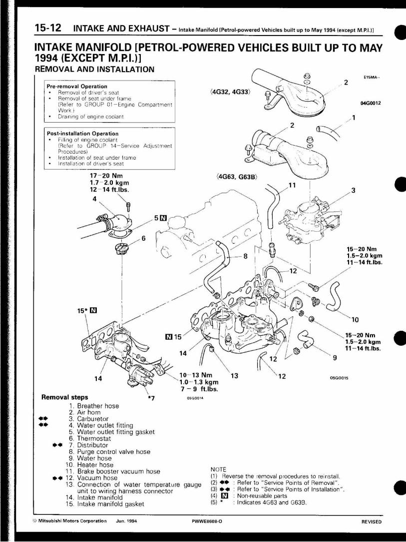
INTAKE MANIFOLD [PETROL-POWERED VEHICLES BUILT UP TO MAY 1994 (EXCEPT M.P.I.)] REMOVAL AND INSTALLATION
Pre-removal Operation Removal of driver's seat Removal of seat under frame (Refer to GROUP Ol-Engine Compartment Work)
• Draining of engine coolant
Post-installation Operation • Filling of engine coolant
(Refer to GROUP 14-Service Adjustment Procedures)
• Installation of seat under frame Installation of driver's seat
17-20 Nm 1.7-2.0 kgm 12-14ft . lbs.
(4G32, 4G33)
,4G63, G63B)
15* E l
10-13 Nm 1.0-1.3 kgm 7 - 9 ft.lbs
04G0012
1 5 - 2 0 Nm 1.5-2.0 kgm 11-14f t . lbs .
1 5 - 2 0 Nm 1.5-2.0 kgm 1 1 - 1 4 ft.lbs.
05GO015
» «
Removal steps
1. Breather hose 2. Air horn
3. Carburetor
4. Water outlet fitting
5. Water outlet fitting gasket
6. Thermostat
7. Distributor
8. Purge control valve hose 9. Water hose
10. Heater hose
11. Brake booster vacuum hose
• • * 12. Vacuum hose
13. Connection of water temperature gauge unit to wiring harness connector
14. Intake manifold
15. Intake manifold gasket
NOTE
(1) Reverse the removal procedures to reinstall.
(2) * • • : Refer to "Service Points of Removal".
(3) mm : Refer to "Service Points of Installation"
(4) d : Non-reusable parts
(5) * : Indicates 4G63 and G63B.
K> Mitsubishi Motors Corporation Jun. 1994 PWWE8608-O REVISED

I N T A K E A N D E X H A U S T - Intake Manifold [Petrol-powered Vehicles built up to May 1994 (except M.P.I.)] 1 5 - 1 3
SERVICE POINTS OF REMOVAL E 1 5 M B A c
3. REMOVAL OF CARBURETOR
Refer to GROUP 13-Removal, Installation and Inspection of
carburetor.
4. REMOVAL OF WATER OUTLET FITTING
Refer to GROUP 14-Removal, Installation and Inspection of
thermostat.
INSPECTION E1SMBBA
Check the following points; replace the part if a problem is found.
INTAKE MANIFOLD
1. Check for damage or cracking of any part.
2. Check for obstruction of the negative pressure (vacuum) outlet
port, and for obstruction of the water passage or gas passage.
SERVICE POINTS OF INSTALLATION E , 5 M BCA
12. INSTALLATION OF VACUUM HOSES
Refer to GROUP 17-Service Adjustment Procedures.
7. INSTALLATION OF DISTRIBUTOR
Refer to GROUP 16-lgnition System.
© Mitsubishi Motors Corporation Jun. 1994 PWWE8608-O REVISED
15-14 INTAKE AND EXHAUST - ntake Manifold [Petrol-powered Vehicles built up to May 1994 (with M.P.I.)]
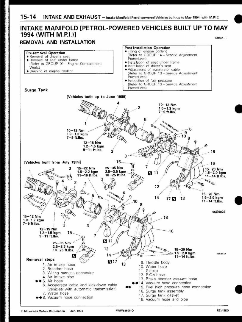
INTAKE MANIFOLD [PETROL-POWERED VEHICLES BUILT UP TO MAY 1994 (WITH M.P.I.)]
E15MA - -
REMOVAL AND INSTALLATION
Pre-removal Operation • Removal of driver's seat • Removal of seat under frame
(Refer to GROUP 01 -Eng ine
Work.) • Draining of engine coolant
Compartment
Surge Tank
Post-installation Operation • Filling of engine coolant
(Refer to GROUP 14-Service Adjustment Procedures)
• Installation of seat under frame • Installation of driver's seat • Adjustment of accelerator cable
(Refer to GROUP 13-Service Adjustment Procedures)
• Inspection of fuel pressure (Refer to GROUP 13-Service Adjustment Procedures)
[Vehicles built up to June 1989]
4 10-13 Nm 1.0-1.3 kgm 7-9 ft.lbs.
[Vehicles built from July 1989]
3
10-12 Nm 1.0-1.2 kgm 7-9 ft.lbs
12-15 Nm 1.2-1.5 kgm 9-11 ft.lbs
T
15-22 Nm 25-35 Nm 1.5-2.2 kgm 2.5-3.5 kgm 11-16 ft.lbs. 18-25 ft.lbs
3
n 1 4 17C3 13
P 8
A 12-15 Nm 1.2-1.5 kgm 9-11 ft.lbs >f
25-35 Nm 2.5-3.5 kgm 18-25 ft.lbs
15-20 Nm 1.5-2.0 kgm 11-14 ft.lbs.
15-20 Nm 1.5-2.0 kgm 11-14 ft.lbs.
05G0029
10-12 Nm 1.0-1.2 kgm 7-9 ft.lbs.
Removal steps
1. Air intake hose 2. Breather hose 3. Wiring harness connector 4. Air intake pipe
* • * 5. Air hose 6. Accelerator cable and kick-down cable
(vehicles with automatic transmission 7. Water hose
• • • 8 . Vacuum hose connection
15-20 Nm 1.5-2.0 kgm 11-14 ft.lbs.
Throttle body Water hose Gasket P.C.V.hose Brake booster vacuum hose Vacuum hose connection Fuel high pressure hose connection Surge tank assembly Surge tank gasket Vacuum hose and pipe
® Mitsubishi Motors Corporation Jun. 1994 PWWE8608-O REVISED

I N T A K E A N D E X H A U S T - Intake Manifold [Petrol-powered Vehicles built up to May 1994 (with M.P.I.}] 15-15
Inkate Manifold 10-13 Nm 1.0-1.3 kgm 7-9 ft.lbs.
12-15 Nm 1.2-1.5 kgm 9-11 ft.lbs.
17-20 Nm 1.7-2.0 kgm 12-14 ft. lbs.
^
13 Nm 1.0-1.3 kgm 7-9 ftlbs
15-20 Nm 1.5-2.0 kgm 11-14 ft.lbs.
15-20 Nm 1.5-2.0 kgm 11-14 ft.lbs.
10-13 Nm 1.0—1.3 kgm 7 -9 ftlbs.
18-25 Nm 1.8-2.5 kgm 13-18 ft.lbs.
05G0052
Removal steps
19. Fuel injector harness connector 20. Fuel high pressure hose connection
• • • • 2 1 . Delivery pipe, fuel injector and pressure regulator
• • 2 2 . Insulator 23. Heater hose 24. Wiring harness connector 25. Water outlet fitting 26. Water outlet fitting gasket 27. Thermostat
28. Distributor 29. Ignition coil 30. Surge tank stay 31. Intake manifold stay 32. Intake manifold 33. Intake manifold gasket
NOTE (1) Reverse the removal procedures to reinstall (2) • • (3) • • (4) d
Refer to "Service Points of Removal". Refer to "Service Points of Installation" Non-reusable parts
© Mitsubishi Motors Corporation Jun. 1994 PWWE8608-O REVISED

1 5 - 1 6 I N T A K E A N D E X H A U S T - Intake Manifold [Petrol-powered Vehicles built up to May 1994 (with M.P.I.)]
SERVICE POINTS OF REMOVAL E 1 S M B A D
15. DISCONNECTION OF FUEL HIGH PRESSURE HOSE
Relieve pressure in the fuel pipe line to prevent fuel outflow.
(See GROUP 13-Service Adjustment Procedures)
Caution Cover fuel pipe line with rag after relieving pressure as certain pressure may still remain.
21. REMOVAL OF DELIVERY PIPE, FUEL INJECTOR AND PRESSURE REGULATOR
Remove delivery pipe with fuel injector and pressure regulator
on.
Caution Do not drop injector when removing delivery pipe.
INSPECTION E15MB8B
Check the following points; replace the part if a problem is found.
INSPECTION OF SURGE TANK
1. Check surge tank for defect or cracks. Replace if defective or
cracked.
2. Check load (negative pressure) of drain port. Check cooling
water and jet air passages for clogging. Clean if required.
INTAKE MANIFOLD
1. Check for damage or cracking of any part.
2. Check load (negative pressure) of drain port. Check cooling water and jet air passages for clogging. Clean if required.
'& Mitsubishi Motors Corporation Jun. 1994 PWWE8608O REVISED
I N T A K E A N D E X H A U S T - Intake Manifold [Petrol-powered Vehicles built up to May 1994 (with M.P.I.)] 1 5 " 1 7
Insulator
ECI400
\ Zd/ j I \ \ \ k yll
Q X . Insulator
x / 05G0023
Air hose band ,^-y
/ \A
• •-• - i _ . r %
z y~v
as
A-&äy
z
"y D An j £rS 1 V
rs -Ö ^T > '
ML f4
/ 05G0021
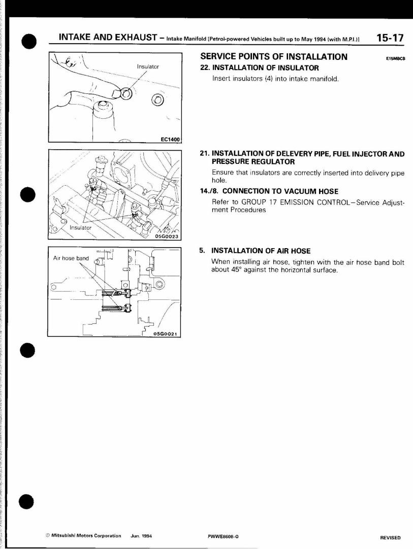
SERVICE POINTS OF INSTALLATION 22. INSTALLATION OF INSULATOR
Insert insulators (4) into intake manifold.
E16MBCB
21. INSTALLATION OF DELEVERY PIPE, FUEL INJECTOR AND PRESSURE REGULATOR
Ensure that insulators are correctly inserted into delivery pipe hole.
14./8. CONNECTION TO VACUUM HOSE
Refer to GROUP 17 EMISSION CONTROL-Service Adjust-ment Procedures
5. INSTALLATION OF AIR HOSE
When installing air hose, tighten with the air hose band bolt about 45° against the horizontal surface.
© Mitsubishi Motors Corporation Jun. 1994 PWWE8608-O REVISED

15-17-1 INTAKE AND EXHAUST - Intake manifold (4G92)
INTAKE MANIFOLD (4G92) REMOVAL AND INSTALLATION
Pre-removal and Post-installation Operation • Carburetor Assembly Removal and
installation (Refer to GROUP 13 - Carburetor.) a/ / t
12
w 05X0031 I 05Y0036
13 ü Specified sealant: 3M Nut Locking Part No. 4171 or equivalent
20-4.0 Nm 2.0-4.0 kgm 14-29 ft.lbs.
12 Nm ,2 kgm
7-9 ft.lbs. 20-35 Nm 2.0-3.5 kgm \ 14-25 ft.lbs.
-. yAfAAZy t yy A A "-A
y y •
V 19-28 N m r 1.9-2.8 kgm
-\ 14-20 ft.lbs K AyA r-.. \ \ \ D
17-22 Nm 1.7-2.2 kgm 12-16 ft.lbs.
05G0100
Specified sealant: 3M ATD Part No. 8660 or equivalent
20-50 Nm 2.0-5.0 kgm 14-36 ft.lbs. 27-34 Nm
2.7-3.4 kgm 20-25 ft.lbs.
8-12 Nm / 0.8-12 kgm 5.8-8.9 ft.lbs. 05G0074
Removal steps
1. Vapor hose and p;oe assembly 2. Fuel vapor separator 3. PCV hose 4 Bi'ake booster vacuum hose connection 5. Water hose 6. Heater hose 7 Vacuum pipe assembly 8. Vacuum connector joint 9. EGR valve
10. EGR gasket 11. Thermo valve 12. Thermo valve
ff 13. Engine coolant temperature sensor M 14. Engine coolant temperature gauge unit ff 15. Intake manifold stay
16. Intake manroid 17. Intake manifold gasket
NOTE (1) Reverse the removal procedures to reinstall. (2)M (3) Cl (4)»
(5A (6)*2
Refer to "Service Points of Installation". Non-reusable parts Vehicles with FBC Vehicles with power steering Vehicles with EGR system
5. Mitsubishi Motors Corporation Jun. 1994 PWWE8608-D ADDED

INTAKE AND EXHAUST - Intake manifold (4G92) 15-17-2
ntake manifold stay _ . J A !
Identification mark
11NQ32
INSPECTION E15MBBA
Check the following points; replace the part if a problem is found.
INTAKE MANIFOLD 1. Check for damage or cracking of any part. 2. Check for obstruction of the negative pressure (vacuum) out-
let port, and for obstruction of the water passage or gas pas-sage.
SERVICE POINTS OF INSTALLATION 15. INSTALLATION OF INTAKE MANIFOLD STAY
(1) Install the intake manifold stay so that the identification mark is facing towards the intake manifold.
(2) After provisionally tightening the bolts at both ends, check to be sure that the stay is secure against the boss, and then tighten to the specified torque.
14. INSTALLATION OF ENGINE COOLANT TEMPERATURE GAUGE UNIT Apply the specified sealant around the thread of engine cool-ant temperature gauge unit and install on the intake man-ifold.
Specified sealant: 3M ATD Part No. 8660 or equivalent
13. INSTALLATION OF ENGINE COOLANT TEMPERATURE SENSOR/12. 11. THERMO VALVE Apply the specified sealant around the thread of engine cool-ant temperature sensor, thermo valve and install on the in-take manifold.
Specified sealant: 3M Nut Locking Part No. 4171 or equivalent
i Mitsubishi Motors Corporation Jun. 1994 PWWE8608-O ADDED
1 5 - 1 7 - 3 INTAKE AND EXHAUST - Intake manifold [4G63 - 16 valve (except M.P.I.)]
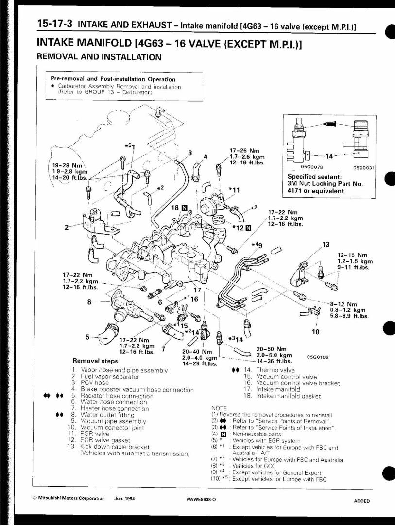
INTAKE MANIFOLD [4G63 - 16 VALVE (EXCEPT M.P.I.)] REMOVAL AND INSTALLATION
Pre-removal and Post installation Operation • Carburetor Assembly Removal and installation
(Refer to GROUP 13 - Carburetor.)
r -s XrX y A N
\ x. ••••-X: ---\ > ^ X ,--'
A E S -----.-•• y Z -----\ i #5-| y
f 17-26 Nm
1 3 \
i 1.7-2.6 kgm
/ 12-19 ft.lbs • J
i 19-28 Nm 05G0O78 I 05X0031 -1.9-2.8 kgm Specif ied sealant 14-20 ft.lbs 3 M Nut Locking Part No V
f *11 4171 or equiva lent .-1 .-y 17-22 Nm
-a S
I 1.7-2.2 kgm '.IC
/ 12-16 ft.lbs ---. 12 H AX / o n h X
/ I \ / 13 49 v
**& / y> /
& o lie X
12-15 Nm ,-,---XX
1.2-1.5 kgm -V
9 - 1 1 ft.lbs -' -- >-S A 17-22 Nm
1.7-2.2 kgm
< * $ 12-16 ft.lbs - © 17 C ^ ^ -•--S3 ^ 1 6 x
8 8 - 1 2 Nm --. i_J
rz=m 0.8-1.2 kgm
r 5.8-8.9 ft.lbs ~
10
z 17-22 Nm 1.7-2.2 kgm
I ^ 2 0 - 5 0 Nm 20 -40 Nm 12-16 ft.lbs 2.0-5.0 kgm 05GO1O2 2.0-4.0 kgm Remova l steps 14-36 ft.lbs 14-29 ft.lbs
1 y '3. 4. b. 6. 7. 8. y.
•iu. 11 VI. \'A
Vapor hose and pipe assembly Fuel vapor separator PCV hose Brake booster vacuum hose connection Radiator hose connection Water hose connection Heater hose connection Water outlet fitting Vacuum pipe assembly Vacuum conector joint EGR valve EGR valve gasket Kick-down cable bracket (Vehicles with automatic transmission)
NOTE
M 14. Thermo valve 15. Vacuum control valve 16. Vacuum control valve bracket 17. Intake manifold 18. Intake manifold gasket
(1) Reverse the removal procedures to reinstall (2)«» (3)M (4) [ f l (5)* (6) *'
(71 *2
Refer to "Service Points of Removal". Refer to "Service Points of Installation" Non-reusable parts Vehicles with EGR system Except vehicles for Europe with FBC and Australia - A/T
(7) *? : Vehicles for Europe with FBC and Australia
(8) *3 : Vehicles for GCC
(9) * 4 : Except vehicles for General Export (10) * 5 : Except vehicles for Europe with FBC
® Mitsubishi Motors Corporation Jun. 1994 PWWE8608-O ADDED
I N T A K E A N D E X H A U S T - Intake manifold [4G63 - 16 valve (except M.P.I.)] 1 5 - 1 7 - 4
Mating marks
Water outlet fitting
I Bead diameter: 2.4-3.0 mm (0.09-0.12in.)|
05W0017
Projection
' / /
Water outlet fitting
04S0O33
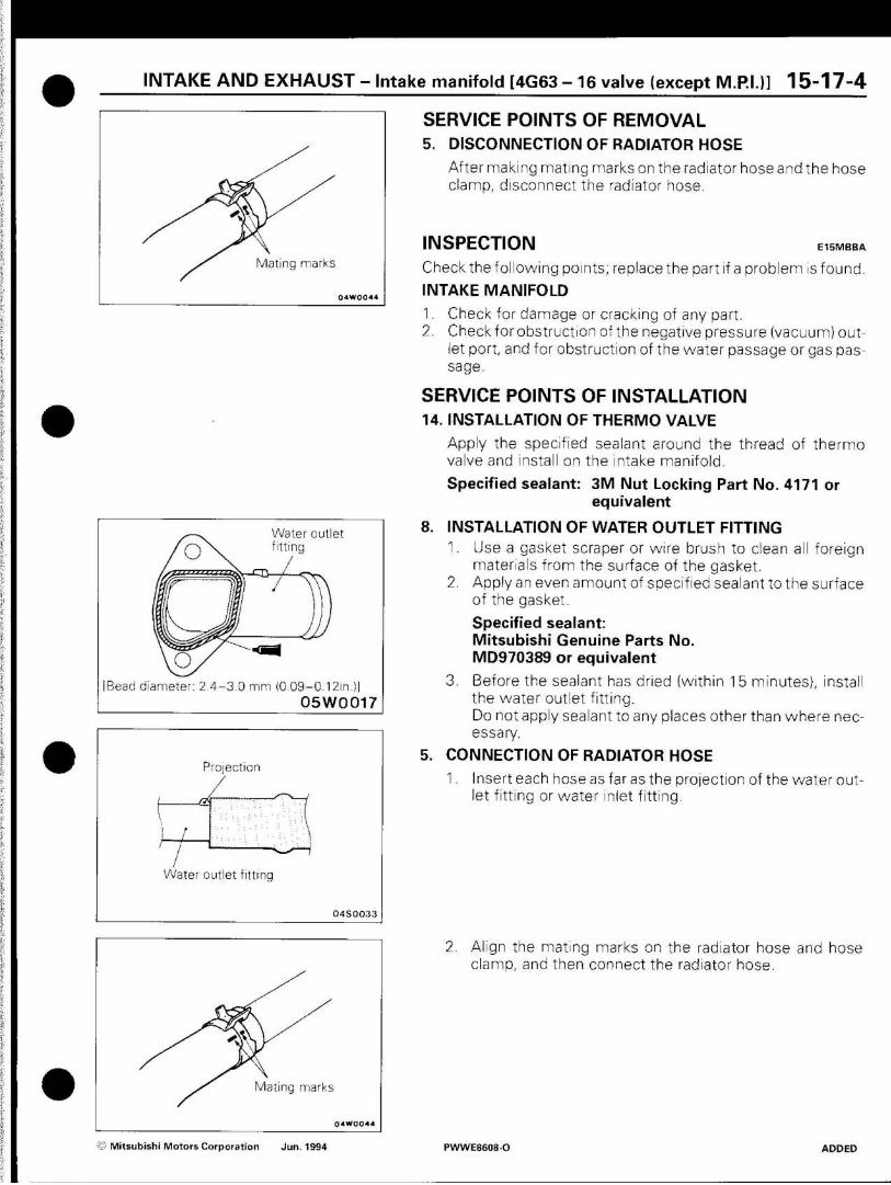
SERVICE POINTS OF REMOVAL 5. DISCONNECTION OF RADIATOR HOSE
After making mating marks on the radiator hose and the hose clamp, disconnect the radiator hose.
I N S P E C T I O N E15MBBA
Check the following points; replace the part if a problem is found.
INTAKE MANIFOLD
1. Check for damage or cracking of any part.
2. Check forobstruction of the negative pressure (vacuum) out-let port, and for obstruction of the water passage or gas pas-sage.
SERVICE POINTS OF INSTALLATION 14. INSTALLATION OF THERMO VALVE
Apply the specified sealant around the thread of thermo valve and install on the intake manifold.
Specified sealant: 3M Nut Locking Part No. 4171 or equivalent
8. INSTALLATION OF WATER OUTLET FITTING 1. Use a gasket scraper or wire brush to clean all foreign
materials from the surface of the gasket. 2. Apply an even amount of specified sealant to the surface
of the gasket.
Specified sealant: Mitsubishi Genuine Parts No. MD970389 or equivalent
3. Before the sealant has dried (within 15 minutes}, install the water outlet fitting. Do not apply sealant to any places other than where nec-essary.
5. CONNECTION OF RADIATOR HOSE
1. Insert each hose as far as the projection of the water out-let fitting or water inlet fitting.
Mating marks
2. Align the mating marks on the radiator hose and hose clamp, and then connect the radiator hose.
X Mitsubishi Motors Corporation Jun. 1994 PWWE8608-O ADDED
15-17-5 I N T A K E A N D E X H A U S T - Intake manifold [4G63 and 4G64-16 valve (with M. P.I.)]
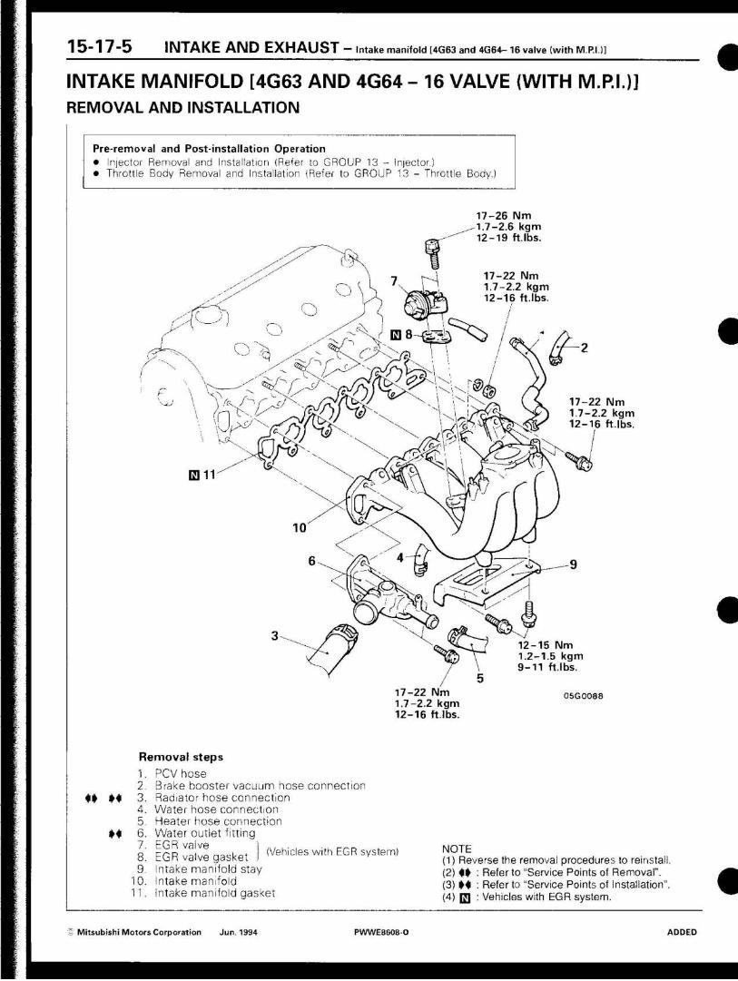
INTAKE MANIFOLD [4G63 AND 4G64 - 16 VALVE {WITH M.P.I.)] REMOVAL AND INSTALLATION
Pre-removal and Post-installation Operation
• Injector Removal and Installation (Refer to GROUP 13 - Injector.) • Throttle Body Removal and Installation (Refer to GROUP 13 - Throttle Body.)
4» M
M
17-26 Nm 1.7-2.6 kgm 12-19 f t lbs.
17-22 Nm 1.7-2.2 kgm 12-16 ft.lbs.
m 17-22 Nm 1.7-2.2 kgm 12-16 ft.lbs.
12-15 Nm 1.2-1.5 kgm 9-11 ft.lbs.
17-22 Nm 1.7-2.2 kgm 12-16 ft.lbs.
05G0088
Removal steps
1. PCVhose 2. Brake booster vacuum hose connection 3. Radiator hose connection 4. Water hose connection 5. Heater hose connection 6. Water outlet fitting 7. EGR vaive I ... , . . K, nr.n
8. EGR vaive gasket I (Vehicles with EGR system) 9. Intake manifold stay
10. Intake manifold 11. Intake manifold gasket
NOTE (1) Reverse the removal procedures to reinstall. (2)1» ( 3 )M (4) UJ
Referto "Service Points of Removal". Refer to "Service Points of Installation" Vehicles with EGR system.
- Mitsubishi Motors Corporation Jun. 1934 PWWE8608O ADDED

I N T A K E A N D E X H A U S T - Intake manifold [4G63 and 4G64 - 16 valve (with M.P.I.|] 15-17-6
ating marks
SERVICE POINTS OF REMOVAL 3. DISCONNECTION OF RADIATOR HOSE
After making mating marks on the radiator hose and the hose clamp, disconnect the radiator hose.
INSPECTION Checkthefollowing points; replacethe part if a problem isfound.
INTAKE MANIFOLD
1. Check for damage or cracking of any part. 2. Check for obstruction of the negative pressure (vacuum) out-
let port, and for obstruction of the water passage or gas pas-sage.
Water outlet fitting
[Bead diameter: 2.4-3.0 mm (0.09-0.12in.)J
05W0017
Projection
Water outlet fitting
04S0033
Mating marks
SERVICE POINTS OF INSTALLATION 6 INSTALLATION OF WATER OUTLET FITTING
1. Use a gasket scraper or wire brush to clean all foreign materials from the surface of the gasket.
2. Apply an even amount of specified sealant to the surface of the gasket.
Specified sealant: Mitsubishi Genuine Parts No. MD970389 or equivalent
3. Before the sealant has dried (within 15 minutes), install the water outlet fitting. Do not apply sealant to any places other than where nec-essary.
3. CONNECTION OF RADIATOR HOSE
1. Insert each hose as far as the projection of the water out-
let fitting or water inlet fitting.
2. Align the mating marks on the radiator hose and hose clamp, and then connect the radiator hose.
© Mitsubishi Motors Corporation Jun. 1994 PWWE8608-D ADDED
Tb" lÖ I N T A K E A N D E X H A U S T — Exhaust Manifold (Petrol-powered vehicles built up to May 1994)
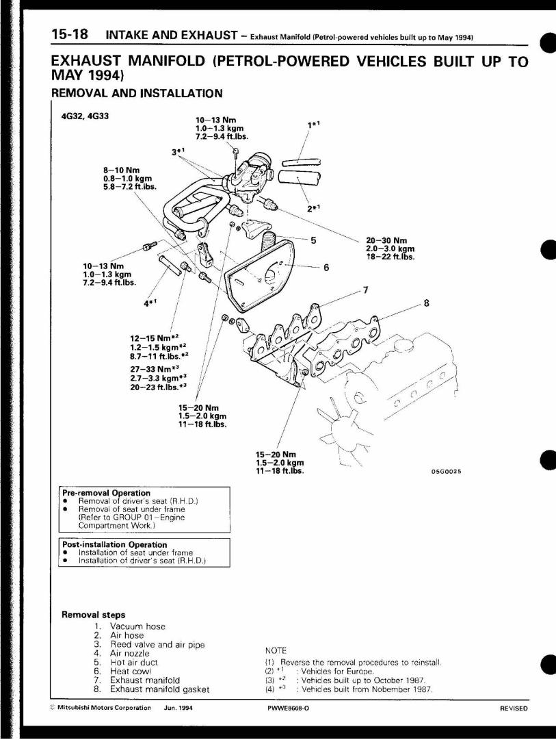
EXHAUST MANIFOLD (PETROL-POWERED VEHICLES BUILT UP TO MAY 1994} REMOVAL AND INSTALLATION
4G32, 4G33 10-13 Nm 1.0-1.3 kgm 7.2-9.4 ftlbs
1*1
8-10 Nm 0.8-1.0 kgm 5.8-7.2 ft.lbs
20-30 Nm 2.0-3.0 kgm 18-22 ft.lbs.
10-13 Nm 1.0-1.3 kgm 7.2-9.4 ftlbs.
12-15 Nm*2
1.2-1.5 kgm*2
8.7-11 ft.lbs.*2
27-33 Nm*3
2.7-3.3 kgm*3
20-23 ft.lbs.*3
15-20 Nm 1.5-2.0 kgm 11 — 18 ft.lbs.
15-20 Nm 1.5-2.0 kgm 11-18 ft.lbs. 05GO025
Pre-removal Operation • Removal of driver's seat (R.H.D. • Removal of seat under frame
(Refer to GROUP 01 -Engine Compartment Work.)
Post-installation Operation • Installation of seat under frame • Installation of driver's seat (R.H.D.;
Removal 1. 2. 3. 4. 5. 6, 7. 8.
steps Vacuum hose Air hose Reed valve and air pipe Air nozzle Hot air duct Heat cowl Exhaust manifold Exhaust manifold gasket
NOTE (1) Reverse the removal procedures to reinsta (2) *1 : Vehicles for Europe. (3) *2 : Vehicles built up to October 1987. (4) *3 : Vehicles built from Nobember 1987.
'& Mitsubishi Motors Corporation Jun 1994 PWWE8608-O REVISED

I N T A K E A N D E X H A U S T - Exhaust Manifold (Petrol-powered vehicles built up to May 1994) 1 5 ~ 1 9
4G63
12-15 Nm*3
1.2-1.5 kgm*3
8.7-11 ftlbs.*3
27-33 Nm** 2.7-3.3 kgm*4
20-23 ft.lbs.*4
0*1 10-13 Nm 1.0-1.3 kgm 7.2-9.4 ft.lbs.
15-20 Nm 1.5-2.0 kgm 11—18 ft.lbs.
8-10 Nm 0.8-1.0 kgm 5.8-9.4 ftlbs.
®Zt\
y 15-20 Nm 1.5-2.0 kgm 11-18ft.lbs.
20-30 Nm*" 2.0-3.0 kgm*2
18-22 ftlbs.*2
15-20 Nm 1.5-2.0 kgm 11-18 ftlbs.
05G0027
Removal steps 1. 2. 3.
4. 5. 6. 7. 8. 9.
Vacuum hose Air hose Reed valve and air pipe
Air nozzle Hot air duct Heat cowl Exhaust manifold Gasket Exhaust manifold gasket
NOTE
(1) Reverse the removal procedures to reinstall. (2) G3 : Non-reusable parts (3) * ' : Vehicles for Australia. (4) *2 : Vehicles equipped with a dual type front exhaust
pipe. (5) *3 : Vehicles built up to October 1987. (6) *A : Vehicles built from November 1987.
© Mitsubishi Motors Corporation Jun. 1994 PWWE8608-O REVISED
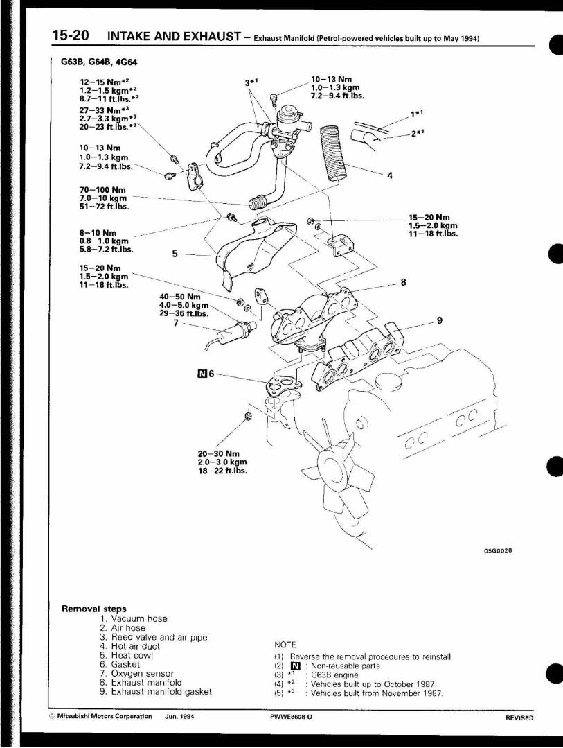
I 3-20 I N T A K E A N D E X H A U S T — Exhaust Manifold (Petrol-powered vehicles built up to May 1994)
G63B, G64B, 4G64
12-15 Nm* 2
1.2-1.5 kgm*2
8.7-11 f t lbs.*2
27-33 Nm*3
2.7-3.3 kgm*3
20-23 ft.lbs.*3
10-13 Nm 1.0-1.3 kgm 7.2-9.4 ft.lbs
70-100 Nm 7.0-10 kgm 51-72 ft.lbs.
8-10 Nm 0.8-1.0 kgm 5.8-7.2 ft.lbs
15-20 Nm 1.5-2.0 kgm 11-18 ft.lbs.
10-13 Nm 1.0-1.3 kgm 7.2-9.4 ft.lbs.
•&> 15-20 Nm 1.5-2.0 kgm 11-18 ft.lbs.
40-50 Nm 4.0-5.0 kgm 29-36 f t lbs
7
20-30 Nm 2.0-3.0 kgm 18-22 ft.lbs.
05G0028
Removal steps 1. Vacuum hose 2. Air hose 3. Reed valve and air pipe 4. Hot air duct 5. Heat cowl 6. Gasket 7. Oxygen sensor 8. Exhaust manifold 9. Exhaust manifold gasket
NOTE
(1) Reverse the removal procedures to reinstall (2) UJ : Non-reusable parts (3) *' : G63B engine (4) *2 : Vehicles built up to October 1987. (5) *3 : Vehicles built from November 1987.
•5 Mitsubishi Motors Corporation Jun. 1994 P W W E 8 6 0 8 O REVISED

INTAKE A N D E X H A U S T - Exhaust Manifold (Petrol-powered vehicles built up to May 1994) 1 5 " 2 1
INSPECTION E15NCAA
Check the following points; replace the part if a problem is found.
EXHAUST MANIFOLD
Check for damage or cracking of any part.
EXHAUST MANIFOLD GASKET
Check for flaking or damage of the gasket.
© Mitsubishi Motors Corporation Jun. 1994 PWWE8608-O REVISED
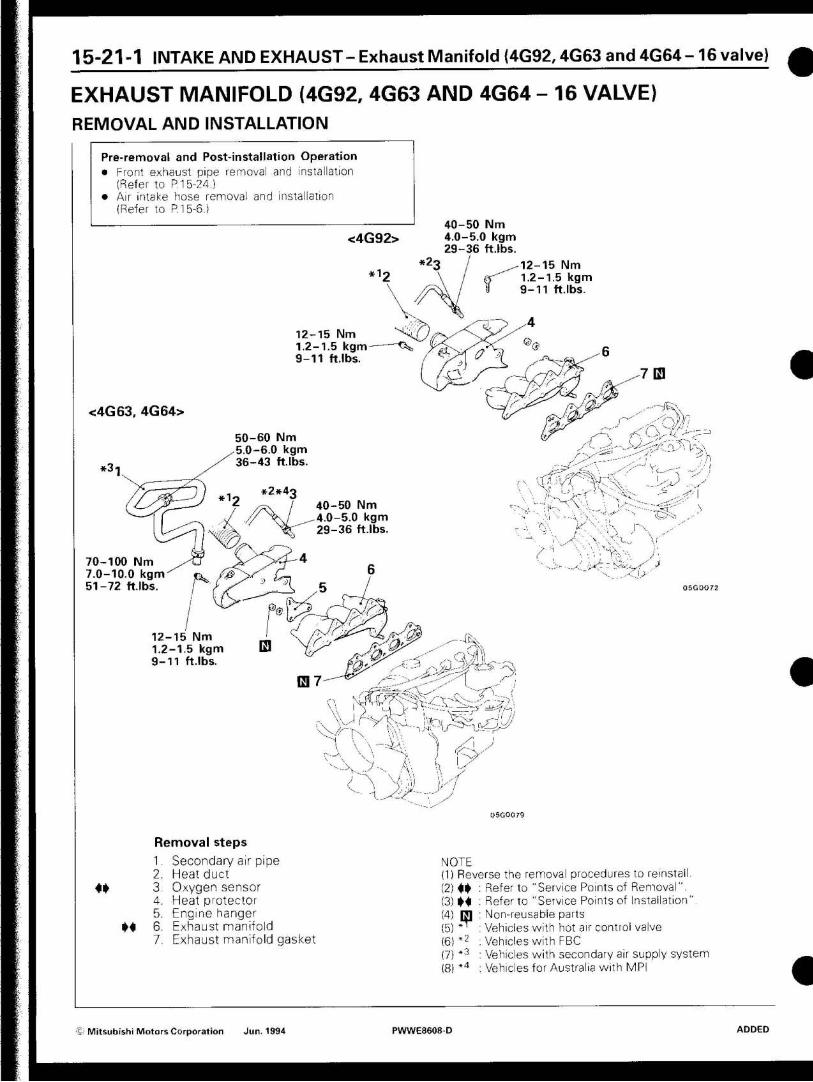
15-21-1 INTAKE AND EXHAUST-Exhaust Manifold {4G92,4G63 and 4G64-16 valve)
EXHAUST MANIFOLD (4G92, 4G63 AND 4G64 - 16 VALVE) REMOVAL AND INSTALLATION
Pre-removal and Post-installation Operation • Front exhaust pipe removal and installation
(Refer to P. 15-24.) • Air intake hose removal and installation
(Refer to P. 15-6.)
<4G92> 40-50 Nm 4.0-5.0 kgm 29-36 ft.lbs.
-12-15 Nm 1.2-1.5 kgm 9-11 ft.lbs.
12-15 Nm 1.2-1.5 k g m - — < \ , 9-11 ft.lbs.
<4G63, 4G64>
50-60 Nm ,5.0-6.0 kgm 36-43 ftlbs.
40-50 Nm 4.0-5.0 kgm 29-36 ft.lbs.
a
70-100 7.0-10.0 kgm 51-72 ft.lbs.
A JA
12-15 Nm 1.2-1.5 kgm 9-11 ft.lbs.
m 7
,AAAI , -yyyyyp-zy
d •••••"' I y
A.A- r ; f ZyyZyr^^dz^y
A. X \ -Ai.
'-->, y --
) A v i ...
) zy i, I x
ar-
Removal steps
1- Secondary air pipe 2. Heat duct
ff 3. Oxygen sensor 4. Heat protector 5. Engine hanger
M 6. Exhaust manifold 7. Exhaust manifold gasket
NOTE (1) Reverse the removal procedures to reinsta (2)«»
(3)M (4) m (5) ~ (6)*2
, 7 } * 3
( 8 ) *4
Refer to "Service Points of Removal". Referto "Service Points of Installation" Non-reusable parts Vehicles with hot air control valve Vehicles with FBC Vehicles with secondary air supply system Vehicles for Australia with MPI
© Mitsubishi Motors Corporation Jun 1994 PWWE8608D ADDED
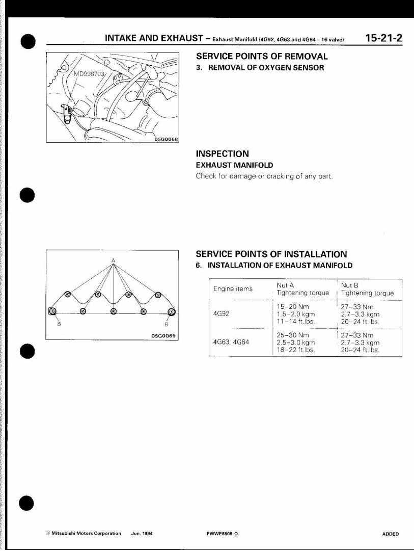
I N T A K E A N D E X H A U S T - Exhaust Manifold (4G92, 4G63 and 4G64 - 16 valve) 15-21-2
VID998703
05G0068
SERVICE POINTS OF REMOVAL 3. REMOVAL OF OXYGEN SENSOR
INSPECTION EXHAUST MANIFOLD
Check for damage or cracking of any part.
05G0069
SERVICE POINTS OF INSTALLATION 6. INSTALLATION OF EXHAUST MANIFOLD
Engine items
4G92
4G63, 4G64
Nut A Tightening torque
15 -20Nm
1.5-2.0 kgm 11-14 ft.lbs.
25-30 Nm 2.5-3.0 kgm
18-22 ft.lbs.
NutB
Tightening torque
27-33 Nm
2.7-3.3 kgm
20-24 ft.lbs.
27-33 Nm 2.7-3.3 kgm 20-24 ft.lbs.
Zi Mitsubishi Motors Corporation Jun. 1994 PWWE8608O ADDED
15-22 I N T A K E A N D E X H A U S T - Intake and Exhaust Manifold (Diesel-powered vehicles)
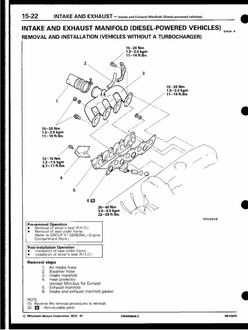
INTAKE AND EXHAUST MANIFOLD (DIESEL-POWERED VEHICLES) REMOVAL AND INSTALLATION (VEHICLES WITHOUT A TURBOCHARGER)
15-20 Nm 1.5-2.0 kgm 11-14 ft.lbs
S
15-20 Nm 1.5-2.0 kgm 11-14 ft.lbs
r m 1 © y / • \ / /
> /
mz) i 3
/ ®-y .--.--<
,-y .--15-20 Nm < 1.5-2.0 kgm <x •v. 11-14 ftlbs
\ --.. ^
/Ok I ~~.
12-15 Nm 1.2-1.5 kgm A 8.7-11 ftlbs \ /
/ -
/ /
\ /
/
6m 30-40 Nm V 3.0-4.0 kgm 22-29 ft.lbs
0SG0026
Pre-removal Operation • Removal of driver's seat (R.H.D.) • Removal of seat under frame
(Refer to GROUP 01 GENERAL-Engine Compartment Work.)
Post-installation Operation • Installation of seat under frame • Installation of driver's seat (R.H.D.)
Removal steps 1. Air intake hose 2. Breather hose 3. Intake manifold 4. Heat protector
(except Mini-bus for Europe) 5. Exhaust manifold 6. Intake and exhaust manifold gasket
NOTE (1) Reverse the removal procedures to reinstall. (2) E I : Non-reusable parts
© Mitsubishi Motors Corporation NOV. 87 PWWE8608 C REVISED

I N T A K E A N D E X H A U S T — Intake and Exhaust Manifold (diesel-powered vehicles) 1 5 ~ 2 3
INSPECTION E15UCAA
Check the following points; replace the part if a problem is found.
INTAKE AND EXHAUST MANIFOLD
Check for damage or cracking of any part.
© Mitsubishi Motors Corporation DEC. 88 PWWE8608-E REVISED
15-23-1 I N T A K E A N D E X H A U S T — Intake and Exhaust Manifold (diesel powerd vehicles)
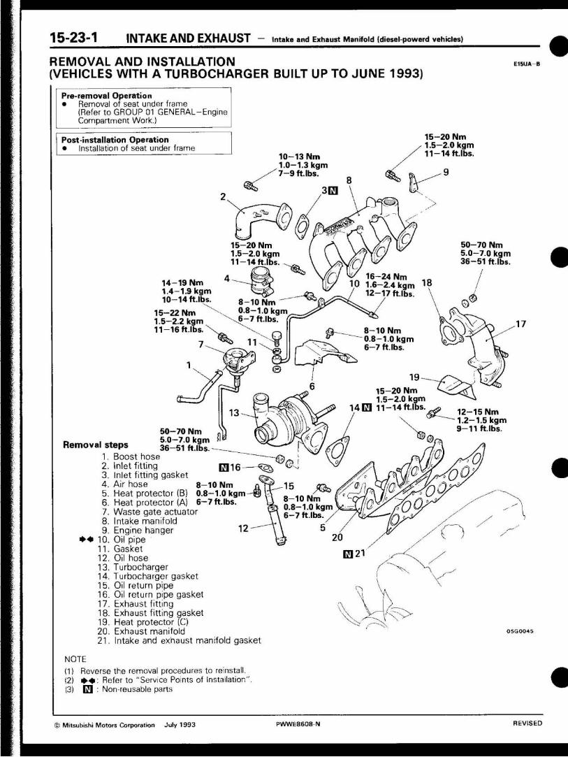
R E M O V A L A N D I N S T A L L A T I O N
( V E H I C L E S W I T H A T U R B O C H A R G E R B U I L T U P T O J U N E 1 9 9 3 ) E15UA B
Pre-removal Operation • Removal of seat under frame
(Refer to GROUP 01 GENERAL-Engine Compartment Work.)
Post-installation Operation • Installation of seat under frame
10-13 Nm 1.0-1.3 kgm 7 -9 ft. lbs.
15-20 Nm 1.5-2.0 kgm 11-14 ft.lbs. o
14-19 Nm 1.4-1.9 kgm 10-14 ft.lbs.
15-22 Nm 1.5-2.2 kgm 11-16 ft.lbs.
er
15-20 Nm 1.5-2.0 kgm 11-14 ft.lbs.
50-70 Nm 5.0-7.0 kgm 36-51 ft.lbs.
Removal steps
8-10 Nm 0.8-1.0 kgm 6-7 ft.lbs.
1. Boost hose 2. Inlet fitting 3. Inlet fitting gasket 4. Air hose 5. Heat protector (B) 6. Heat protector (A) 7. Waste gate actuator 8. Intake manifold 9. Engine hanger
* • 10. Oil pipe 11. Gasket 12. Oil hose 13. Turbocharger 14. Turbocharger gasket 15. Oil return pipe 16. Oil return pipe gasket 17. Exhaust fitting 18. Exhaust fitting gasket 19. Heat protector (C) 20. Exhaust manifold 21. Intake and exhaust manifold gasket
NOTE
(1) Reverse the removal procedures to reinstall. (2) • • : Referto "Service Points of installation". (3) E l : Non-reusable parts
8-10 Nm 0.8-1.0 kgm 6-7 ft.lbs
M> 8-10 Nm 0.8-1.0 kgm 6-7 ft.lbs
16-24 Nm 1.6-2.4 kgm 12-17 ftlbs.
8-10 Nm 0.8-1.0 kgm 6-7 ftlbs.
15-20 Nm 1.5-2.0 kgm 11-14ft.lbs.
<3>
50-70 Nm 5.0-7.0 kgm 36-51 ft.lbs.
12-15 Nm 1.2-1.5 kgm 9-11 ft. lbs.
to
© Mitsubishi Motors Corporation July 1993 PWWE8608 N REVISED
I N T A K E A N D E X H A U S T — Intake and Exhaust Manifold (diesel-powerd vehicles) 15_23_2
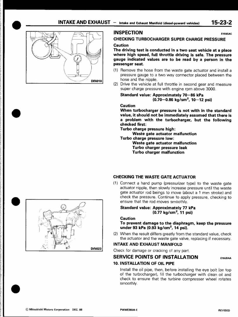
INSPECTION E15UCAC
CHECKING TURBOCHARGER SUPER CHARGE PRESSURE
Caution The driving test is conducted In a two seat vehicle at a place where high speed, full throttle driving is safe. The pressure gauge indicated values are to be read by a person in the passenger seat.
(1) Remove the hose from the waste gate actuator and install a pressure gauge to a two way connector placed between the hose and the nipple.
(2) Drive the vehicle at full throttle in second gear and measure super charge pressure with engine rpm above 3000.
Standard value: Approximately 70—86 kPa (0.70-0.86 kg/sm2, 10-12 psi)
Caution When turbocharger pressure is not with in the standard value, it should not be Immediately assumed that there is a problem with the turbocharger, but the following checked first: Turbo charge pressure high:
Waste gate actuator malfunction Turbo charge pressure low:
Waste gate actuator malfunction Turbo charger pressure leak Turbo charger malfunction
CHECKING THE WASTE GATE ACTUATOR
(1) Connect a hand pump (pressurizer type) to the waste gate actuator nipple, then slowly increase pressure until the waste gate actuator rod beings to move (about a 1 mm stroke) and check the pressure. Continue to apply pressure, checking to ensure that the rod moves smoothly.
Standard value: Approximately 77 kPa (0.77 kg/cm2, 11 psi)
Caution To prevent damage to the diaphragm, keep the pressure under 93 kPa (0.93 kg/cm2, 14 psi).
(2) When the result differs greatly from the standard value, check the actuator and the waste gate valve, replacing if necessary.
INTAKE AND EXHAUST MANIFOLD
Check for damage or cracking of any part.
SERVICE POINTS OF INSTALLATION .«UDAA
10. INSTALLATION OF OIL PIPE
Install the oil pipe, then, before installing the eye bolt (on top of the turbocharger), fill the turbocharger with clean oil and check to ensure that the turbine compresser wheel rotates smoothly.
\; 1X2 i
A
--.
\ Ji \
A 7 DN010
if'" 0 DIN023
© Mitsubishi Motors Corporation DEC. 88 PWWE860B E REVISED
1 5-23-3 I N T A K E A N D E X H A U S T - Intake and Exhaust Manifold (diesel-powered vehicles)
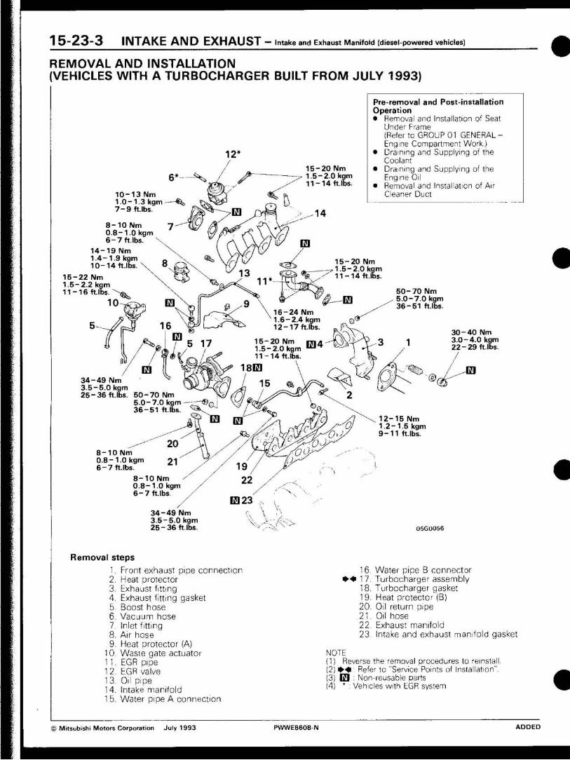
R E M O V A L A N D I N S T A L L A T I O N
( V E H I C L E S W I T H A T U R B O C H A R G E R B U I L T F R O M J U L Y 1 9 9 3 )
1 0 - 1 3 Nm 1.0-1.3 kgm —«fe 7 - 9 ft lbs.
8 - 1 0 N m 0.8-1 .0 kgm 6 - 7 ft.lbs.
1 4 - 1 9 Nm 1 .4 -1 .9 kgm 1 0 - 1 4 ft.lbs.
Pre-removal and Post-installation Operation
Removal and Installation of Seal Under Frame (Refer to GROUP 01 GENERAL -Engine Compartment Work.) Draining and Supplying of the Coolant Draining and Supplying of the Engine Oil Removal and Installation of Air Cleaner Duct
1 5 - 2 2 Nm 1.5-2.2 kgm 1 1 - 1 6 ft lbs.
1 0
20 Nm 2.0 kgm 14 ft.lbs
1 5 - 2 0 Nm 1.5-2.0 kgm 1 1 - 1 4 ft.lbs
5 0 - 7 0 Nm 5.0-7.0 kgm 3 6 - 5 1 ft.lbs
24 Nm 2.4 kgm 17 ft.lbs
1 5 - 2 0 Nm 1.5-2.0 kgm 1 1 - 1 4 ft.lbs
70 Nm 7A
k.?
m Ai^cX 51 ft.lbs.
3 0 - 4 0 Nm 3.0-4.0 kgm 2 2 - 2 9 ft.lbs.
/
3 4 - 4 9 Nm 3.5-5.0 kgm 2 5 - 3 6 ft.lbs.
1 2 - 1 5 Nm 1.2-1.5 kgm 9 - 1 1 ft lbs.
8 - 1 0 Nm 0.8-1 .0 kgm 6 - 7 f t lbs.
8 - 1 0 Nm 0 .8-1 .0 kgm 6 - 7 f t lbs
3 4 - 4 9 Nm 3.5-5.0 kgm 2 5 - 3 6 ft.lbs.
R e m o v a l s teps
1. Front exhaust pipe connect ion
2. Heat protector
3. Exhaust f itt ing
4. Exhaust f i t t ing gasket
5. Boost hose
6. Vacuum hose
1. Inlet f i t t ing
8. Air hose
9. Heat protector (A)
10. Waste gate actuator
11 . EGR pipe
1 2 EGR valve
13. Oil pipe
1 4. Intake manifold
1 5. Water pipe A connect ion
05GOO56
1 6. Water pipe B connector
* * 1 7. Turbocharger assembly
18. Turbocharger gasket
19. Heat protector (B)
20. Oil return pipe
21. Oil hose 22. Exhaust manifold
23. Intake and exhaust manifold gasket
NOTE (1) Reverse the removal procedures to reinstall. (2) * ^ i : Refer to "Service Points of Installation". (3) E l : Non-reusable parts (4) ' : Vehicles with EGR system
© Mitsubishi Motors Corporation July 1993 PWWE8608-N ADDED
I N T A K E A N D E X H A U S T — Intake and Exhaust Manifold IDiesel-powered vehicles) 1 5 - 2 3 - 4
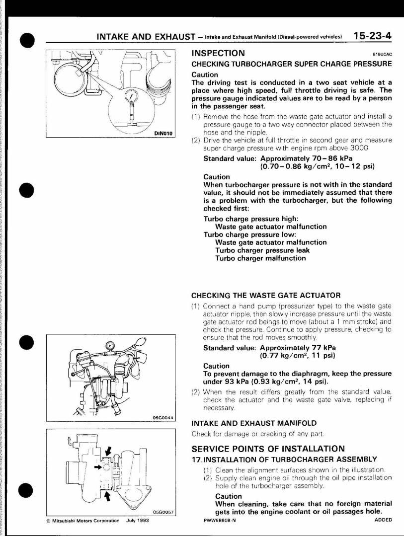
INSPECTION E15UCAC
CHECKING TURBOCHARGER SUPER CHARGE PRESSURE
Caution The driving test is conducted in a two seat vehicle at a place where high speed, full throttle driving is safe. The pressure gauge indicated values are to be read by a person in the passenger seat.
(1) Remove the hose from the waste gate actuator and install a pressure gauge to a two way connector placed between the hose and the nipple.
(2) Drive the vehicle at full throttle in second gear and measure super charge pressure with engine rpm above 3000
Standard value: Approximately 7 0 - 8 6 kPa ( 0 . 7 0 - 0 . 8 6 kg/cm 2 , 1 0 - 1 2 psi)
Caution When turbocharger pressure is not with in the standard value, it should not be immediately assumed that there is a problem with the turbocharger, but the following checked first:
Turbo charge pressure high: Waste gate actuator malfunction
Turbo charge pressure low: Waste gate actuator malfunction Turbo charger pressure leak Turbo charger malfunction
r
k f*% AAA
^r.
y
t- <&r
05G0044
05G0057
© Mitsubishi Motors Corporation July 1993
CHECKING THE WASTE GATE ACTUATOR
(1) Connect a hand pump {pressurizer type) to the waste gate actuator nipple, then slowly increase pressure until the waste gate actuator rod beings to move {about a 1 mm stroke) and check the pressure. Continue to apply pressure, checking to ensure that the rod moves smoothly.
Standard value: Approximately 77 kPa ( 0 7 7 kg/cm 2 , 11 psi)
Caution To prevent damage to the diaphragm, keep the pressure under 93 kPa (0.93 kg/cm 2 , 14 psi).
(2) When the result differs greatly from the standard value, check the actuator and the waste gate valve, replacing if necessary.
INTAKE AND EXHAUST MANIFOLD
Check for damage or cracking of any part.
SERVICE POINTS OF INSTALLATION 17.INSTALLATION OF TURBOCHARGER ASSEMBLY
(1) Clean the alignment surfaces shown in the illustration. (2) Supply clean engine oil through the oil pipe installation
hole of the turbocharger assembly.
Caution When cleaning, take care that no foreign material gets into the engine coolant or oil passages hole.
PWWE8608-N ADDED
15-24 INTAKE AND EXHAUST - Exhaust Pipes and Mufflers
EXHAUST PIPES AND MUFFLERS REMOVAL AND INSTALLATION
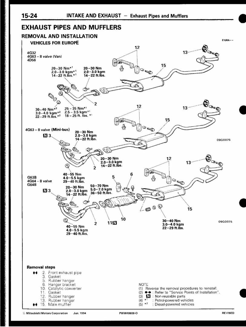
VEHICLES FOR EUROPE
4G32 4G63 - 8 valve (Van) 4D56
20-30 Nm*1
2.0-3.0 kgm*1
14-22 ft.lbs.*1
4G63 - 8 valve (Mini-bus)
0 3
20-30 Nm 2.0-3.0 kgm 14-22 ft.lbs
30-40 Nm*2 2 5 - 3 5 N m * ' 3.0-4.0 kgm*2 2.5 - 3.5 kgm 22-29 ftlbs.*2 18 -25 ft. lbs.
20-30 Nm 2.0-3.0 kgm 14-22 ft.lbs. 09G0076
20-30 Nm 2.0-3.0 kgm 14-22 ft.lbs.
G63B 4G64 - 8 valve G64B
lH 3
< ^
40-55 Nm 4.0—5.5 kgm 29-40 ft.lbs.
20-30 Nm 2.0-3.0 kgm 14-22 ft.lbs.
50-70 Nm 5.0-7.0 kgm 36-50 ft.lbs.
40-55 Nm 4.0-5.5 kgm 29-40 ft.lbs.
30-40 Nm 3.0—4.0 kgm 22-29 ft.lbs.
09G0O75
Removal steps
M
M
2. 3. 5. 6.
10. 11. 12. 13. 15.
Front exhaust pipe Gasket Rubber hanger Hanger bracket Catalytic converter Gasket Rubber hanger Rubber hanger Main muffler
NOTE (1) Reverse the removal procedures to reinstall. (2} • • * (3) E l (4) *1
(5) *2
Refer to "Service Points of Installation Non-reusable parts Petrol-powered vehicles Diesel-powered vehicles
z Mitsubishi Motors Corporation Jun. 1994 PWWE8608-O REVISED
INTAKE A N D EXHAUST - Exhaust Pipes and Mufflers 15-24-1
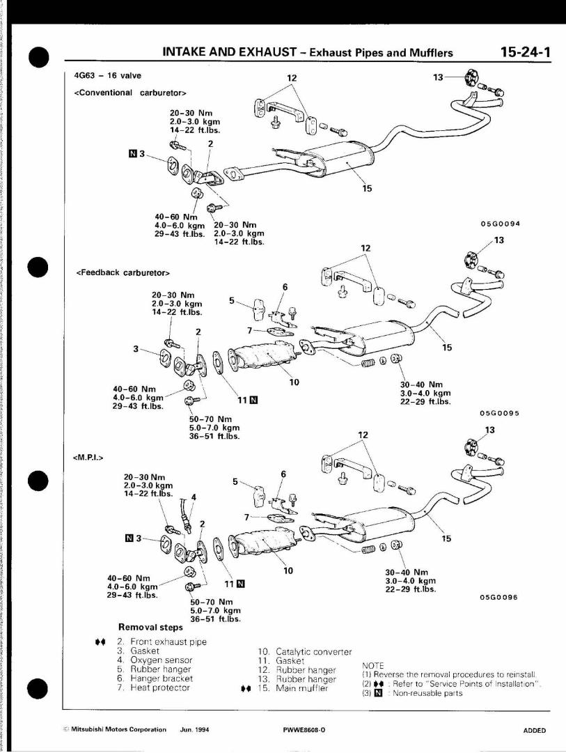
4G63 - 16 valve
-^Conventional carburetor>
20-30 Nm 2.0-3.0 kgm 14-22 ft.lbs.
^%$L
40-60 Nm 4.0-6.0 kgm 20-30 Nm 29-43 ft.lbs. 2.0-3.0 kgm
14-22 ft.lbs.
<Feedback carburetor>
20-30 Nm 2.0-3.0 kgm 14-22 ft.lbs.
0 5 G 0 0 9 4
<S£)
40-60 Nm 4.0-6.0 kgm 29-43 ft.lbs.
30-40 Nm 3.0-4.0 kgm 22-29 ft.lbs.
50-70 Nm 5.0-7.0 kgm 36-51 ftlbs.
<M.P.I.>
0 5 G 0 0 9 5
^
©55» 0
20-30 Nm 2.0-3.0 kgm 14-22 ft.lbs.
13 3
M
40-60 Nm y*& \ 4.0-6.0 k g m ' ' ' (SF»'J
29-43 ft.lbs. 50-70
\ l i d
Nm 5.0-7.0 kgm 36-51
Removal steps
2. Front exhaust pipe 3. Gasket 4. Oxygen sensor 5. Rubber hanger 6. Hanger bracket 7. Heat protector
ft.lbs.
M
10. 11. 12. 13. 15.
10
Catalytic converter Gasket Rubber hanger Rubber hanger Main muffler
30-40 Nm 3.0-4.0 kgm 22-29 ft.lbs.
05G0096
NOTE (1) Reverse the removal procedures to reinstall (2) M : Refer to "Service Points of Installation' (3) d : Non-reusable parts
: Mitsubishi Motors Corporation Jun. 1994 PWWE8608 0 ADDED
15-25 INTAKE AND EXHAUST - Exhaust Pipes and Mufflers
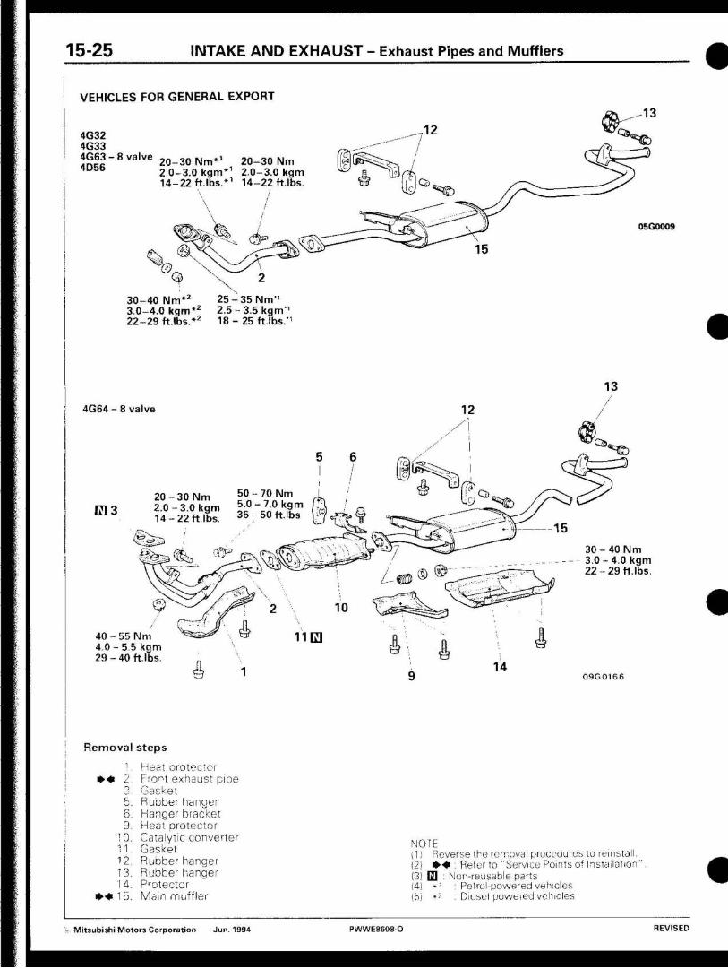
VEHICLES FOR GENERAL EXPORT
4G32 4G33 4G63 - 8 valve 4D56
2 0 - 3 0 N m * 1
2.0-3.0 kgm* 1
14 -22 ft.lbs.*1
2 0 - 3 0 Nm 2.0-3.0 kgm 14-22 ft.lbs.
•*"©
05G0009
3 0 - 4 0 N m * 2
3.0-4.0 kgm* 2
2 2 - 2 9 ft.lbs.*2
2 5 - 3 5 N m - 1
2 . 5 - 3 . 5 kgm - 1
18 - 25 ft.lbs.*1
4G64 - 8 valve
133
40 - 55 N 4 . 0 - 5 5 kgm 29 - 40 ft lbs.
5 0 - 7 0 N m 5 . 0 - 7 . 0 kgm 36 - 50 f t lbs
30 Nm 3.0 kgm 22 ft.lbs
« ^
3 0 - 40 Nm 3.0 - 4.0 kgm 2 2 - 2 9 ft.lbs.
09G0166
Removal steps
* • •
*•••
6
9
10
11
12
13
14
15
Heat oro tectcr
Freist exhaust pipe Gasket
Rubber hanger Hanger bracket Heat protector
Catalytic conver ter Gasket
Rubber hanger
Rubber hanger
Protector
Main muf f le r
NOTE (1! Reverse the removal procedures to reinstall. (2) m-m : Refer to "Service Points of Installation'
(3) El : Non-reusable parts (4) * ! : Petrol-powered vehicles \b) *7 : Diesel powered vehicles
z Mitsubishi Motors Corporation Jun. 1994 PWWE8608-O REVISED

I N T A K E A N D E X H A U S T - Exhaust Pipes and Mufflers 15-25-1
G33B
20 - 30 Nm 2.0-3.0 kgm 14 -22 ft.lbs.
50 - 70 Nm 5.0 - 7.0 kgm 36 -50 ft.lbs.
25 - 35 Nm 2.5-3.5 kgm 18-25 ft.lbs.
09G0164
"TO
30 - 40 Nm 3.0-4.0 kgm 22 -29 ft.lbs
^ f ö
20-30 Nm 2.0-3.0 kgm 14-22 ft.lbs.
4.0-6.0 kgm (S\ X 29-43 ft.lbs. ^ \
40-60 Nm
4G92 <Hong Kong>
30-40 Nm 3.0-4.0 kgm 22-29 ft.lbs.
70 Nm 5.0-7.0 kgm 36-51 ft.lbs.
05G0097
Removal steps
*>« 2. 3. 5. 6. 7.
9. 10. 11. 12. 13. 14.
• « 1 5 .
Front exhaust pipe
Gasket Rubber hanger Hanger bracket Heat protector Protector (Except for Hong Kong G33B) Heat protector Catalytic converter Gasket Rubber hanger Rubber hanger Protector Main muffler
NOTE (1) Reverse the removal procedures to reinstall. (2) • • : Refer to "Service Points of Installation" (3) Q : Non-reusable parts
© Mitsubishi Motors Corporation Jun. 1994 PWWE86Q8-D REVISED
15-25-2 INTAKE AND EXHAUST - Exhaust Pipes and Mufflers
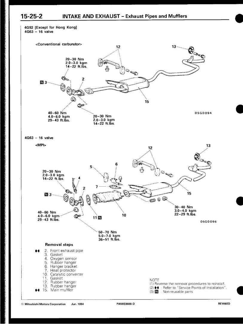
4G92 [Except for Hong Kong] 4G63 - 16 valve
Conventional carburetor>
20-30 Nm 2.0-3.0 kgm 14-22 ft.lbs. /
E] 3
* ©
40-60 Nm 4.0-6.0 kgm 29-43 ft.lbs.
20-30 Nm 2.0-3.0 kgm 14-22 ft.lbs.
05GD094
4G63 - 16 valve
<MPI>
20-30 Nm 2.0-3.0 kgm 14-22 ft.lbs.
E13
40-60 Nm 4.0-6.0 kgm 29-43 ftlbs.
^
«*©
30-40 Nm 3.0-4.0 kgm 22-29 ft.lbs.
0 5 G 0 0 9 6
50-70 Nm 5.0-7.0 kgm 36-51 ftlbs.
Removal steps
M 2. Front exhaust pipe 3. Gasket 4. Oxygen sensor 5. Rubber hanger 6. Hanger bracket 7. Heat protector
10. Catalytic converter 11. Gasket 12. Rubber hanger 13. Rubber hanger
H 15. Main muffler
NOTE (1) Reverse the removal procedures to reinstall. (2) M : Refer to "Service Points of Installation" (3) E| : Non-reusable parts
(e) Mitsubishi Motors Corporation Jun. 1994 PWWE8608-D REVISED

INTAKE A N D EXHAUST - Exhaust Pipes and Mufflers 15-25-3
VEHICLES FOR AUSTRALIA VAN (4G63 enginel [Vehicles built up to September 1988] Diesel powered Van
20 - 30 Nm 2 . 0 - 3 . 0 kgm 1 4 - 2 2 ft.lbs.
Hö
05G0009
2 5 - 3 5 N m 2.5 - 3 . 5 kgm 1 8 - 2 5 ft.lbs.
Van (4G64 engine) [Vehicles built up to September 1988] Petrol powered Van [Vehicles built from October 1988 up to May 1994] Mini-bus [Vehicles built up to May 1994]
2 0 - 3 0 N m 2 . 0 - 3 . 0 kgm 5 0 - 7 0 N m 1 4 - 2 2 ft.lbs. 5 . 0 - 7 . 0 kgm
3 6 - 5 0 ft.lbs.
E13
40 - 55 Nm 4.0 - 5.5 kgm 29 - 40 ft.lbs.
H b
Am®
30 - 40 Nm - — 3.0 - 4.0 kgm
22 - 29 ft.lbs.
09G0165
Removal
I. • » • 2.
3. 5. 6. 8. 9.
10. 11. 12. 13. 14.
* « 1 5 .
Steps
Heat protector
Front exhaust pipe Gasket
Rubber hanger
Hanger bracket Protector
Heat protector
Catalytic converter Gasket
Rubber hanger
Rubber hanger
Protector
Main muffler
NOTE (1} Reverse the removal procedures to reinstall. (2) • ^ : Refer to "Service Points of Installation" (3) E l : Non-reusable parts (4) *••' ; 2WD
© Mitsubishi Motors Corporation Jun. 1994 PWWE8608-O REVISED
15-25-4 INTAKE AND EXHAUST - Exhaust Pipes and Mufflers
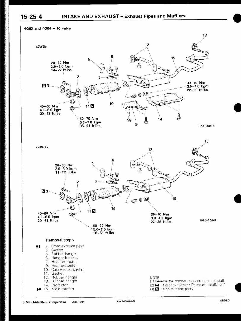
4G63 and 4G64 - 16 valve
<2WD>
20-30 Nm 2.0-3.0 kgm 14-22 ft.lbs.
0 3
40-60 Nm 4.0-6.0 kgm 29-43 ft.lbs.
# **©
30-40 Nm 3.0-4.0 kgm 22-29 ft.lbs.
\ 50-70 Nm 5.0-7.0 kgm 36-51 ft.lbs. 0 5 G O O 9 8
<4WD>
20-30 Nm 2 0-3.0 kgm 14-22 ft.lbs.
0 3
40-60 Nm 4.0-6.0 kgm 29-43 ft.lbs.
- © 30-40 Nm 3.0-4.0 kgm 22-29 ft.lbs. 05G0099
M
M
Removal steps
2. Front exhaust pipe 3. Gasket 5. Rubber hanger 6. Hanger bracket 7. Heat protector 9. Heat protector
10. Catalytic converter 11. Gasket 12. Rubber hanger 13. Rubber hanger 14. Protector 15. Main muffler
50-70 Nm 5.0-7.0 kgm 36-51 ft.lbs.
NOTE (1) Reverse the removal procedures to reinstall. (2) M : Referto "Service Points of Installation' (3) 0 : Non-reusable parts
t: Mitsubishi Motors Corporation Jun. 1994 PWWE8608-0 ADDED
INTAKE AND E X H A U S T - Exhaust Pipes and Mufflers 1 5 - 2 6
INSPECTION E1SRCAA
• Check the mufflers and pipes for corrosion or damage. • Check rubber hangers for deterioration or damage. • Check for gas leakage from mufflers or pipes.
SERVICE POINTS OF INSTALLATION E 1 5 «DAD
15. INSTALLATION OF MAIN MUFFLER /2, FRONT EX-HAUST PIPE After fully tightening front exhaust pipe and main muffler, check to be sure there is no contact with the chassis at any place and there is no twisted hanger.
S Mitsubishi Motors Corporation Jun. 1994 PWWE8608-O REVISED
NOTES
GS Mitsubishi Motors Corporation Jun. 1994 PWWE8608-O ADDED