1.5 kva operation manual in the box · pdf filethe 1.5 kva system is designed to operate only...
TRANSCRIPT

1.5 KVA OPERATION MANUALDated: 05/13/2011Document No.: 1.5KVA_OM Page 1 of 11
IntroductionReasonable care and safe methods should be practiced. Check local codes and requirements before installation. This manual contains important information for the safe use of this product. Read this manual completely before using this product and refer to it often for continued safe product use.DO NOT THROW AWAY OR LOSE THIS MANUAL. Keep it in a safe place so that you may refer to it when needed.
WarningIn The BoxAlways disconnect the Unit from the receptacle power source and battery before handling or making any adjustments to the system.
Battery Backup Warning:
TerminologyHere are descriptions of terms which you may not be familiar with:Electrolyte: Typically a mixture of water and sulfuric acid, it is commonly referred to as battery acid.
Plates: Originally made of lead, now fabricated from lead oxide. Plates connect to the battery terminals and provide a structure for the chemicals that create current. There are several plates in each cell; each insulated from the other by separators.
Sulfating: As the battery discharges, its plates get covered with lead sulfate. During recharging, the lead surface leaves the plate and recombines with electrolyte. If the lead sulfate remains on the plates for an extended period of time (over two months), it hardens and recharging will not remove it. This reduces the effective plate area and the battery’s capacity.
1. Risk of electrical shock this Unit has not been investigated for use in outdoor areas.
2. Risk of electrical shock. Connect only to a properly grounded, three pronged grounding type receptacle. Under any circumstances, do not remove the grounding prong from the power cord.
3. Do not smoke, use sparkable electrical devices or open flame when working on this unit!
4. Do not install Unit in locations classified as hazardous per N.E.C., ANSI/NFPA 70 - 1999.
FAILURE TO HEED ABOVE CAUTIONS COULD RESULT IN INJURY OR DEATH.
The 1.5 KVA System is designed to operate only one pump, the one supplied with the unit. Using anything other than the pump supplied with the system will cause damage to the Unit and void the warranty.
Inverter and Battery Box(Batteries Not included)
Fuse Bar
Battery Leads

1.5 KVA OPERATION MANUALDated: 05/13/2011Document No.: 1.5KVA_OM Page 2 of 11
Important SafetyInstructions
Before proceeding further, kindly go through the safety instructions carefully.General Precautions:• Before using the inverter read all instructions and
caution markings on the inverter, the batteries & all appropriate sections of this instruction manual.
• Do not expose the inverter to any type of chemicals. The inverter is designed for interior use only.
• Do not disassemble the inverter; take it to a qualified service center when service or repair is required. Opening by unqualified personnel can lead to electrical shock or fire hazard and void the warranty.
• To reduce risk of electric shock, disconnect all wiring before cleaning.
• Warning: Avoid exposing the inverter or batteries to any type of explosive gases (in the vicinity, as batteries generate explosive gases during normal operation). Provide proper ventilation. The battery enclosures should be designed to prevent accumulation and concentration by hydrogen gas in “pockets” at the top of the compartment. Vent the battery compartment from the highest point. A sloped lid can also be used to direct the flow to the vent opening location. To reduce the risk of the battery explosion, follow all the instructions of the battery supplier or any equipment you intend to use in the vicinity of batteries.
• Use the correct insulated tools to make AC/DC wiring connections.
• Do not install this inverter on or near flammable materials (plywood, chemicals, gas online etc.)
Deep Discharging: A deep discharge occurs when a battery is discharged to less than 20% of its capacity (80% depth of discharge).
Knowing Your InverterIn its most basic form, an Inverter transforms Direct Current (DC) to Alternating Current (AC). The battery pack acts as a reserve to ensure continuous supply of power whenever mains supply from utility power is not available. The inverter is used to charge the batteries when normal utility power is available and converts the battery’s DC to AC voltage to run the pump when utility power is lost.
CAUTION:Personal Precautions:• Someone should be within the range of your
voice to come to your aid when you work near batteries.
• Have plenty of fresh water and soap nearby in the event that battery acid contact skin, clothing or eyes.
• Wear complete eye and clothing protection.• Avoid touching eyes while working near batteries.
Wash your hands when done.• If battery acid comes in contact with skin or
clothing, wash immediately with soap and water. If acid
Stratification: Over time, a battery’s electrolyte (liquid) tends to separate. The electrolyte at the top of the battery becomes watery while at the bottom it becomes more acidic. This effect is corrosive to the plates.
DSP based Sine Wave OutputDSP based circuit will increase the efficiency and accuracy of the inverter. This technology makes possible a high level of internal inverter management and generates a Sine Wave Output.
Auto ResetInverter has auto-reset function in case of Overload Short Circuit. It will reset itself automatically and will make 8 attempts for Overload and 4 attempts for Short Circuit.
Protection Circuit The inverter is protected from low battery voltage and over current conditions. When the inverter senses one of these situation, it will protect itself by disconnecting from the load, and will signal an error condition by displaying along with the buzzer.
Automatic Low Battery Cutout (LBCO)The inverter protects your batteries from damage caused by over-discharging, by automatically shutting itself off when battery voltage falls to a
Features

1.5 KVA OPERATION MANUALDated: 05/13/2011Document No.: 1.5KVA_OM Page 3 of 11
preset level. This feature is called the low battery cutout. The inverter comes from the factory with the LBCO voltage set at 10 volts per battery.
Automatic High Battery CutoutWhen battery voltage rises above 14 volts per battery, the charger stops its normal charging and comes to the trickle mode so as to take care of the self-discharging of the battery. The charger automatically resumes operation when battery voltage drops below 13 volts per battery.
Over Current cutoutThe inverter is protected from over current conditions. When the load being run demands more current then the inverter can handle, the inverter will shutdown automatically along with the LED display
Volts AC DropoutThe inverter monitors the voltage of the AC power passing through to the charge and AC loads. When AC voltage falls below the preset level, the inverter automatically transfers from AC to DC power (i.e. it comes to UPS mode). This dropout voltage is factory preset at 90-110 volts. So when the AC voltage drops to this level, the inverter automatically transfers from AC to DC power.
Reduces Power Consumption of the InverterThe circuitry design reduces power intake of the inverter when the battery is in trickle charge mode and also minimizes the evaporation of battery electrolyte.
Battery Safety1. CAUTION-Do not dispose of battery in a fire.
The battery may explode.
2. CAUTION-A battery can present a risk of severe burn and injury from high short circuit current. The following precautions should be observed when working on batteries.
3. CAUTION-Do not open or mutilate the battery. Released electrolyte is harmful to the skin and eyes. It may be toxic.
4. CAUTION-The electrolyte is a dilute sulfuric acid that is harmful to the skin and eyes. It is electrically conductive and corrosive. The following procedures should be observed:
• If electrolyte contacts the skin, wash it off immediately.
• If electrolyte contacts the eyes, flush thoroughly and immediately with water. Seek medical attention.
• Spilled electrolyte should be washed down with a suitable acid neutralizing agent. A common practice is to use a solution of approximately one pound (500 grams) bicarbonate of soda to approximately one gallon (4 liters) of water. The bicarbonate of soda solution be added until the evidence of reaction (foaming) has ceased. The resulting liquid should be flushed with water and the area dried.
5. Caution: Do not reverse the battery connections, as it will blow the battery fuse. A power cord has been provided to connect the inverter to incoming AC wall outlet.
Your Unit operates on 24VDC battery power when in the power fail mode. A UL recognized deep cycle marine battery should be used. There are two principal types of batteries: starting and deep cycle. There are several different types of battery constitutions including liquid led acid, nickel iron, nickel cadmium, alkaline and maintenance free. Batteries are sealed or vented.
Starting BatteriesStarting batteries are designed for high cranking power but not deep cycling, Do not use them with your inverter. They do not affect the inverter, but they will simply not last long in a deep cycle application. They use lot of thin plates to maximize the surface area of the battery. This allows very high starting current but less run time when the battery is cycled.Deep Cycle BatteriesDeep Cycle batteries are best suited for use with the inverter. They are designed to have the majority of their capacity used before recharge. Available in many sizes and types, be sure to use at least a 110AH battery.
Battery Requirements
BATTERIES NOT INCLUDED

1.5 KVA OPERATION MANUALDated: 05/13/2011Document No.: 1.5KVA_OM Page 4 of 11
Battery Maintenance1. If you are using AGM maintenance free Batteries you do not need to perform any maintenance to
your batteries. For all other batteries refer to the manufacturer recommended battery maintenance section.
2. Maintenance or replacement of batteries should be performed or supervised by personnel knowledgeable of batteries and the required precautions.
Replacing Battery1. Wear full eye protection and protective clothing.
2. When replacing the battery/batteries, use the same type and size battery/batteries. See battery requirements (Page 3).
• CAUTION-The electrolyte is a dilute sulfuric acid that is harmful to the skin and eyes. It is electrically conductive and corrosive. The following procedures should be observed:
• Do not lay tools or metal objects on top of the batteries
• Use tools with insulated handles
• Use tools with insulated handles
3. Unplug the unit from the wall.
4. Follow the Installation Instructions found on page 5 of this manual, starting with step 8 and working back to step 1.
5. Remove and safely dispose of old batteries.
6. Install new batteries per the Installation Instructions on page 5.

1.5 KVA OPERATION MANUALDated: 05/13/2011Document No.: 1.5KVA_OM Page 5 of 11
Installation Instructions
Remove all packing and contents from the battery box enclosure. The contents should include: Inverter, quick connect lead and fuse link.
Find a suitable place to set the unit . Keep in mind that the unit should be placed in a area where water and moisture will not splash or drip on the unit, the fan inlet on the sides of the enclosure will not be obstructed and where a properly grounded three prong dedicated receptacle is within reach of the power cord.
Remove watches, rings, or other metal objects.
Use tools with insulated handles.
Do not lay tools or metal parts on top of batteries.
1. Facing the front of the battery box, install a battery on the front of the box with the NEGATIVE(-) terminal to the left. See Figure A.
2. Install the second battery in the back of the box with the POSITIVE (+) terminal on the left side. See Figure A.
3. Install the quick connect leads through the hole provided in the left side of the battery box enclosure. Connect the Red lead to the POSITIVE(+) battery terminal. Connect the Blue lead to the NEGATIVE (-) battery terminal. See Figure B.
4. Install the fuse link between the POSITIVE and NEGATIVE on the right side of the batteries. Make sure all battery connection are properly tighten to 75 inch pounds. Install battery cover back on the battery box. See Figure C.
5. Install the inverter on the lid with the display facing the front of the battery box.
load powered by the inverter should also work at this point, since a portion of the AC power is passed through the inverter to the power the load.
10. Testing:
Unplug the power cord from the wall outlet. The inverter will beep four times. With the Battery Bars cycling from top to bottom, the battery percentage will slowly start to drop. The inverter is now in DC mode, taking the battery power and using it to power the load uninterrupted. Make sure you plug the inverter back into the wall outlet.
The above steps will complete a function test of the inverter. If all areas pass, the inverter is ready for use. If any areas fail, see the troubleshooting table.
6. Verify that the MCB (Main Circuit Breaker) on the back is in the OFF position.
7. Plug the inverter power cord into a 120Vac dedicated 3 prong outlet.
8. Connect the quick connect assembly together from inverter to batteries. See Figure D.
DO NOT PLUG IN ANY PUMP OTHER THAN THE ONE SUPPLIED WITH THE UNIT. PLUGGING IN A DIFFERENT PUMP, OR MORE THAN ONE PUMP, WILL VOID THE WARRANTY.
9. Powering Up:
To charge your batteries, make sure the MCB (Main Circuit Breaker) is in the ON position. The LCD display will come on and show the condition of the batteries. If the batteries are fully charged, the battery display will have all bars lit and show 100%. If batteries are charging, the Battery display will cycle the bars from bottom to top and show the percentage of charge. This shows that the charger is working properly in AC mode. Any AC
Tools NeededA pipe wrench, pliers, adjustable wrench, and screwdriver will be needed.

1.5 KVA OPERATION MANUALDated: 05/13/2011Document No.: 1.5KVA_OM Page 6 of 11
DETAIL A
NEGATIVE TERMINAL(BLUE WIRE) POSITIVE TERMINAL
(RED WIRE)
POSITIVE TERMINAL
NEGATIVE TERMINAL
BA
TT
ER
IES
NO
T I
NC
LUD
ED
Figure D
Figure A
Figure B Figure C
1.5 KVA OPERATION MANUALDated: 05/13/2011Document No.: 1.5KVA_OM Page 7 of 11
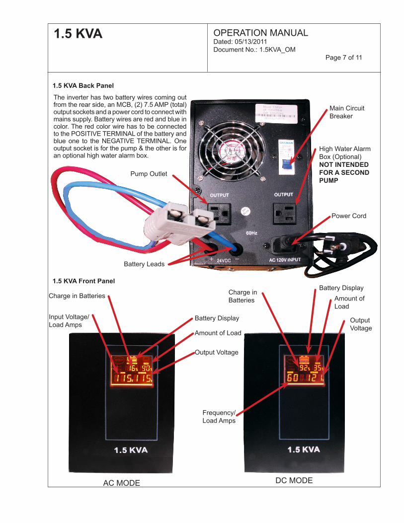
1.5 KVA Back Panel
1.5 KVA Front Panel
Pump Outlet
Battery Leads
Power Cord
High Water Alarm Box (Optional)NOT INTENDED FOR A SECOND PUMP
Main Circuit Breaker
The inverter has two battery wires coming out from the rear side, an MCB, (2) 7.5 AMP (total) output sockets and a power cord to connect with mains supply. Battery wires are red and blue in color. The red color wire has to be connected to the POSITIVE TERMINAL of the battery and blue one to the NEGATIVE TERMINAL. One output socket is for the pump & the other is for an optional high water alarm box.
AC MODE DC MODE
Output Voltage
Output Voltage
Amount of Load
Amount of Load
Battery Display
Battery DisplayCharge in Batteries Charge in
Batteries
Input Voltage/ Load Amps
Frequency/ Load Amps

1.5 KVA OPERATION MANUALDated: 05/13/2011Document No.: 1.5KVA_OM Page 8 of 11
Installing the Backup Pump 3. Test run your system on AC power by activating the switch, then unplug the power supply from the electrical outlet and test the pump on DC power by activating the vertical float switch on the pipe. Be sure to plug the power unit plug back into the wall outlet.
4. After an extended period of power loss, your battery voltage will not be adequate to run your pump. However, battery voltage may recover and allow brief periods
of operation.
Sump pump ON level must be lower than the backup pump ON level. Set the backup pump switch higher than the primary switch.
1. Place the pump into the pit. Secure the discharge piping and attach the switch to the pipe. Make sure the switch ON level is at least 4 inches below the top of your pit and it is set at a level higher than the primary switch’s ON level. Once in place, tighten the switch clamp securely to the pipe.
2. Once the switch is set in place and the dis-charge piping is properly installed, you can piggy back the pump and the switch plug into the receptacle located on the power supply. Then plug the power supply into the wall outlet. To test the Unit, simply unplug it from the receptacle
and add water to the sump until pump pumps the sump down. Only run the Pump supplied with the Battery Back-Up System for a few cycles. You can repeat this if you wish, but it is not necessary. If the Unit works the first time, it is sure to work time and time again. Be sure that you remember to plug the Unit back into the receptacle after you have completed the test.
Testing
NOTE: If while testing the Unit the Pump does not turn on, the following steps should be taken:
1. Check the charger and inverter display to see if they are on.
2. Check the circuit breaker.
3. Plug the Pump you have plugged into the Unit directly into a live building receptacle. If the Pump runs, recheck all the battery connections, and battery voltage.
4. Check sump water level to see that Pump is being required to run.
5. If the above items have been thoroughly checked and your pump will still not run when plugged into the Unit, remove the battery from the battery box as described in REPLACING BATTERY on page 5 and return the Unit to the place of purchase for repair or replacement.
SwitchClampedSecurely
To Pipe

1.5 KVA OPERATION MANUALDated: 05/13/2011Document No.: 1.5KVA_OM Page 9 of 11
Warranty is VOID, if...1. Power cord has been cut or the grounding prong has been removed.
2. Unit has been used in an outdoor application.
3. Batteries not meeting the above specifications have been used.
4. Unit has been submerged in water.
5. Unit has been tampered with in any manor not described in the above instructions.
6. Unit has been disassembled by customer.
7. Unit has been applied to products exceeding the maximum capacity of the Unit, i.e., a pump other than the one supplied with the unit or more than one pump.
8. Unit has been applied to the wrong voltage.
Troubleshooting
Symptoms Problems RemedyPump Does Not Run in DC mode
Low Battery Check conditions of batteries and recharge
Pump Does Not Run in DC mode
Loose or corroded battery connection
Check and clean all connections
AC Power is available , but the inverter will not operate in AC mode.
Loose AC output connection
Check all AC out-put connections
Low surge power Weak batteries, battery cables too long
Refer to cable and battery recom-mendation in this manual
Unit overheats Unit is hot Reduce load and let the unit cool down
Symptoms RectificationInverter mode but no power • Check display to see if low
battery condition is present. Remove all loads, unplug the AC power cord, for 10 sec. plug it back in. Allow the battery to charge when the AC Power resumes before running the Inverter on battery again.• Check display to see if fault condition is present.
Inverter does no operate and no message on display
Check the battery connec-tions and the mains connec-tions
Inverter trips frequently at UPS mode
Reduce the load and reset the inverter
Voltage Limits
Mains A.C. Lower Voltage Limit 90 VAC ± 5V
Output Voltage with Full Load 120V/110 ± 10V
Battery Lower Voltage Limit 21 VOC ± 0.2V
Output FrequencyMain Output Frequency Same as Input
Battery Charger Boost Voltage 13.7 ± 0.2V (Per Battery)
Overload 130 ± 3% (With Auto Reset Function)
Technical Specifications

1.5 KVA OPERATION MANUALDated: 05/13/2011Document No.: 1.5KVA_OM Page 10 of 11
StormPro 3 Year Residential Warranty1. Coverage and Term. Metropolitan Industries, Inc. (“Metropolitan”) warrants to the original purchaser (the “Buyer”) of each StormPro product (the “product”), that any part thereof which proves to be defective in material or workmanship within three (3) years from date of manufacture, will be replaced at no charge with a new or remanufactured part, F.O.B. factory. Buyer shall be responsible for all freight charges and all costs of fi eld labor or other charges incurred in the removal and/or reinstallation of any product, part or component thereof.2. Exclusions. THE WARRANTY IS SUBJECT TO THE FOLLOWING CONDITIONS AND EXCLUSIONS: (a) The Warranty excludes products or workmanship which becomes defective as a result of: (i) earthquake, fi re, storms, the elements or any other acts of God; (ii) normal wear and tear from use; (iii) accident, misuse, abuse or neglect; (iv) modifi cations made by Buyer or any third party, other than Metropolitan; and (v) Buyer’s failure to properly install, maintain, service and/or operate the product under normal conditions and according to manufacturer’s instructions. (b) Metropolitan shall not be responsible for, and the Warranty shall not cover, extended damage which occurs because of Buyer’s failure to notify Metropolitan promptly in writing of apparent defects. (c) Any part or component designated as manufactured by anyone other than Metropolitan shall be covered only by the express warranty of the manufacturer thereof. (d) The Warranty shall lapse upon Buyer’s failure to fully comply with the terms and conditions of its contract with Metropolitan, including Buyer’s failure to pay the purchase price for the product or any portion thereof. Buyer’s subsequent compliance with the terms and conditions of any such contract, will not cause the term of the Warranty to extend beyond the time period set forth above. (e) No actions taken by Metropolitan to correct a defect in a product shall extend the Warranty beyond the period set forth above. Metropolitan shall not be obligated to remedy any defect, where otherwise required pursuant to the Warranty unless and until Buyer notifi es Metropolitan in writing of the defect and then only if such notifi cation is made prior to the expiration of the period set forth above.3. Process of Claims and Repairs. Metropolitan agrees that if the product or any part or component thereof shall fail to conform to the terms of this Warranty, Metropolitan shall replace such nonconforming product, part or component at the original point of delivery and furnish instruction for its disposition. Any transportation charges involved in such disposition and all costs of fi eld labor or other charges incurred in the removal and/or reinstallation of any product, part or component thereof shall be the responsibility of Buyer.4. Limitation on Liability. Notwithstanding any provision to the contrary, Metropolitan’s entire liability under this Warranty shall not in the aggregate exceed, and Buyer’s exclusive and sole remedies are, to the extent permitted by law, shall be to secure replacement of the defective product. UNDER NO CIRCUMSTANCES SHALL METROPOLITAN BE LIABLE UNDER THE WARRANTY FOR ANY INDIRECT, PUNITIVE, SPECIAL, EXEMPLARY, CONSEQUENTIAL OR INCIDENTAL DAMAGES (INCLUDING LOST PROFITS, REVENUE, USE OR ECONOMIC ADVANTAGE).5. Express Waiver of Any Other Warranties. THE EXPRESS WARRANTY SET FORTH IN THIS WRITTEN WARRANTY IS THE ONLY WARRANTY MADE BY METROPOLITAN, OR ANY OTHER PARTY, IN CONNECTION WITH ANY PRODUCT PURCHASED FROM METROPOLITAN. NEITHER METROPOLITAN, NOR ANY OTHER PARTY, MAKES ANY OTHER EXPRESS OR IMPLIED WARRANTY WHICH IS NOT SET FORTH HEREIN, AND METROPOLITAN HEREBY DISCLAIMS AND BUYER HEREBY WAIVES ALL IMPLIED WARRANTIES, INCLUDING THE IMPLIED WARRANTY OF MERCHANTABILITY AND THE IMPLIED WARRANTY OF FITNESS FOR A PARTICULAR PURPOSE.6. Not Transferable. The Warranty may not be transferred and shall be void on the sale or other transfer of the product.7. Products and Warranty Subject to Change. Metropolitan reserves the right to make revisions to its products and their specifi cations, and to revise this Warranty and related information without notice.

1.5 KVA OPERATION MANUALDated: 05/13/2011Document No.: 1.5KVA_OM Page 11 of 11
Notes: