15 - lovato l-starter... · 2014-10-28 · rf9 75 4.5 - 7.5 2.2 *** rf9 10 6.3 - 10 4.0 *** rf9 15...
TRANSCRIPT

ISSUE
15
PLUS+

Lovato Electric. The Story of a Family, the Spirit of a Company
Lovato Electric is a proud family owned business
established in Bergamo, Italy in 1922:
the starting point of a great industrial adventure.
Our family of products feature a full range of devices
for a wide array of industry sectors:
Industrial Control, Power Factor Correction, Solar Energy, Power Generation and Energy Management.
We are proud to serve the UK market with a vast stockholding and UK starter assembly in Stourbridge, West Midlands
for same day collection or next day delivery. From here we also exclusively distribute Canalplast trunking, Cabur cable
terminals and Elca transformers.
See 1000’s of our other products in our latest General Catalogue or online at www.Lovato.co.uk
Sales, Technical Support and Customer Care Tel 08458 110 023 or 01384 899700 Fax 08458 110 024 or 01384 891654 Email [email protected] Online Information www.Lovato.co.uk UK Head Office Address Lovato Electric Ltd Lovato House Providence Drive STOURBRIDGE DY9 8HQ
MOTOR CONTROL
PROTECTION
CONTROL AND
SIGNALLING
CIRCUIT ISOLATION
PROTECTION
AUTOMATION AND
CONTROL
ENERGY
MANAGEMENT

2 - CBD Series Feed-Through Terminal Blocks 2-1
CBC Series Feed-Through Terminal Blocks 2-2 Two & Three Level Terminal Blocks 2-3 Fused Terminal Blocks 2-3 Earth Terminal Blocks 2-3 High Current Terminal Blocks 2-3 Distribution Terminals 2-3 Marker Tags 2-4 End Stops, Covers & Brackets 2-4
3 - Standard Slot Panel Trunking 3-1
Narrow Slot Panel Trunking 3-2 ‘EDGE’ Angular Panel Trunking 3-2 Halogen Free Panel Trunking 3-3 DIN Size Panel Trunking 3-3 Flexible Open Slot Trunking 3-4 Trunking Accessories 3-4 Spiral Wrap 3-4
4 - Open-type Panel Transformers 4-1
Part-enclosed Panel Transformers 4-2
1 - Enclosed Direct On-line Starters - Polycarbonate 1-1
Enclosed Star-Delta Starters - Polycarbonate 1-1 Thermal Overload Relays 1-2 Enclosed Star-Delta Starters - Mild Steel 1-2 Manual Motor Starters 1-3 Soft Starters 1-4 AC Motor Drives 1-4 3 Pole Contactors and Polycarbonate Enclosures 1-5 Modular Contactors 1-5 Enclosed Pushbutton Control Stations 1-6 Enclosed Switch Disconnectors 1-7 DC Switch Disconnectors for Solar Applications 1-7 Steel Enclosed Switches, Fuse Switches & Changeovers 1.8 Enclosed Changeover Switches - Plastic 1-9 Rotary Cam Switches 1-9 Empty Enclosures 1-9 Limit Switches 1-10 Signal Towers & Beacons 1-11 Power Supplies 1-12
The products illustrated in this publication are subject to revision or improvement at any time. Catalogue descriptions, technical and operational data as well as other details herein specified do not have any contractual value and must be considered only as an indication. The products must be installed and used only by qualified personnel in accordance with the relevant regulations in force for electrical installations and systems in order to avoid damage or safety hazards. E.&E.O.

Order Code
Control
Voltage
(VAC)
Motor
Power at
400V
(kW)
Horse
Power
(HP)
Max.
Motor
Current
AC3 (A)
Dimensions
H x W x D
(mm)
Compact Direct On Line Starter (3 Phase) - Requires RF9… Overload Relay
DOLC5.5230 230 5.5 7.5 12 175 x 88 x 119
DOLC5.5400 400
Standard Direct On Line Starter (3 Phase) - Requires RF38… Overload Relay
DOLS5.5230 230 5.5 7.5 12 193 x 88 x 134
DOLS5.5400 400
DOLS7.5230 230 7.5 10 18 193 x 88 x 134
DOLS7.5400 400
DOLS11230 230 11 15 25
225 x 110 x 148 DOLS11400 400
DOLS15230 230 15 20 28.5
DOLS15400 400
Standard Direct On Line Starter With Isolator (3 Phase) - Requires RF38… Overload Relay
DOLSW5.5230 230 5.5 7.5 12
225 x 110 x 148
DOLSW5.5400 400
DOLSW7.5230 230 7.5 10 18
DOLSW7.5400 400
DOLSW11230 230 11 15 25
DOLSW11400 400
Direct On Line Reversing Starter FWD/STOP/REV (3 Phase) - Requires RF38… O/L Relay
DOLR5.5230 230 5.5 7.5 12
225 x 110 x148
DOLR5.5400 400
DOLR7.5230 230 7.5 10 18
DOLR7.5400 400
DOLR11230 230 11 15 25
DOLR11400 400
Operational Characteristics - Starters
Insulated polycarbonate enclosure
Operating temperature: -25...+60oC
Storage temperature: -40...+70oC
Degree of protection: IP65 (IP40 for DOLR…)
Certifications and compliance - Starters
Compliant with standards: IEC/EN 60947-1 and IEC/EN
60947-4-1
DOLC…..
DOLS….
DOLSW….
*** IMPORTANT!!! ***
For DOL starters select RF…. overload relay
from page 1-2 for setting motor at full load
current (FLC)
Star-Delta
Starters
Direct On-line
Starters
Order Code
Control
Voltage
(VAC)
Motor
Power at
400V
(kW)
Horse
Power
(HP)
Max.
Motor
Current
AC3 (A)
Dimensions
H x W x D
(mm)
Star Delta Starter - Requires RF38… Overload Relay
YD11230 230 11 15 22
220 x 280 x 170
YD11400 400
YD15230 230 15 20 28
YD15400 400
YD22230 230 22 30 43
YD22400 400
YD30230 230 30 40 60
YD30400 400
Star Delta Starter With Isolator - Requires RF38… Overload Relay
YDSW11230 230 11 15 22
220 x 280 x 170
YDSW11400 400
YDSW15230 230 15 20 28
YDSW15400 400
YDSW22230 230 22 30 43
YDSW22400 400
YDSW30230 230 30 40 60
YDSW30400 400
Operational Characteristics - Star Delta Starters
Insulated polycarbonate enclosure
Operating temperature: -25...+60oC
Storage temperature: -40...+70oC
Degree of protection: IP65
Certifications and compliance - Starters
Compliant with standards: IEC/EN 60947-1 and IEC/EN
60947-4-1
*** IMPORTANT!!! ***
For YD…. Star Delta Starters select RF38….
overload relay from page 1-2 for setting at 58%
of full load current (FLC)
YD….
YDSW….
1-1
BEST
PRICE!
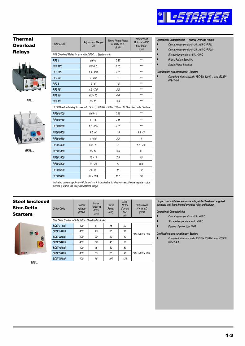
Order Code Adjustment Range
(A)
Three Phase Motor
at 400V DOL
(kW)
Three Phase
Motor at 400V
Star Delta
(kW)
RF9 Overload Relay for use with DOLC…. Starters only
RF9 1 0.6 -1 0.37 ***
RF9 1V5 0.9 -1.5 0.55 ***
RF9 2V3 1.4 - 2.3 0.75 ***
RF9 33 2 - 3.3 1.1 ***
RF9 5 3 - 5 1.5 ***
RF9 75 4.5 - 7.5 2.2 ***
RF9 10 6.3 - 10 4.0 ***
RF9 15 9 - 15 5.5 ***
RF38 Overload Relay for use with DOLS, DOLSW.,DOLR ,YD and YDSW Star Delta Starters
RF38 0100 0.63 - 1 0.25 ***
RF38 0160 1 - 1.6 0.55 ***
RF38 0250 1.6 - 2.5 0.75 ***
RF38 0400 2.5 - 4 1.5 2.2 - 3
RF38 0650 4 - 6.5 2.2 4
RF38 1000 6.3 - 10 4 5.5 - 7.5
RF38 1400 9 - 14 5.5 11
RF38 1800 13 - 18 7.5 15
RF38 2300 17 - 23 11 18.5
RF38 3200 24 - 32 15 22
RF38 3800 32 ~ 38A 18.5 30
Operational Characteristics - Thermal Overload Relays
Operating temperature: -20...+55oC (RF9)
Operating temperature: -25...+60oC (RF38)
Storage temperature: -50...+70oC
Phase Failure Sensitive
Single Phase Sensitive
Certifications and compliance - Starters
Compliant with standards: IEC/EN 60947-1 and IEC/EN
60947-4-1
RF38….
Indicated powers apply to 4-Pole motors; it is advisable to always check the nameplate motor
current is within the relay adjustment range.
Thermal
Overload
Relays
Order Code
Control
Voltage
(VAC)
Motor
Power at
400V
(kW)
Horse
Power
(HP)
Max.
Motor
Current
AC3
(A)
Dimensions
H x W x D
(mm)
Star Delta Starter With Isolator - Overload included
SDSI 11415 400 11 15 22
300 x 300 x 200 SDSI 15415 400 15 20 28
SDSI 22415 400 22 30 42
SDSI 30415 400 30 40 56
SDSI 45415 400 45 60 83
500 x 400 x 200 SDSI 55415 400 55 75 98
SDSI 75415 400 75 100 135
Hinged door mild steel enclosure with painted finish and supplied
complete with fitted thermal overload relay and isolator.
Operational Characteristics
Operating temperature: -25...+60oC
Storage temperature: -40...+70oC
Degree of protection: IP65
Certifications and compliance - Starters
Compliant with standards: IEC/EN 60947-1 and IEC/EN
60947-4-1
SDSI...
Steel Enclosed
Star-Delta
Starters
RF9….
1-2
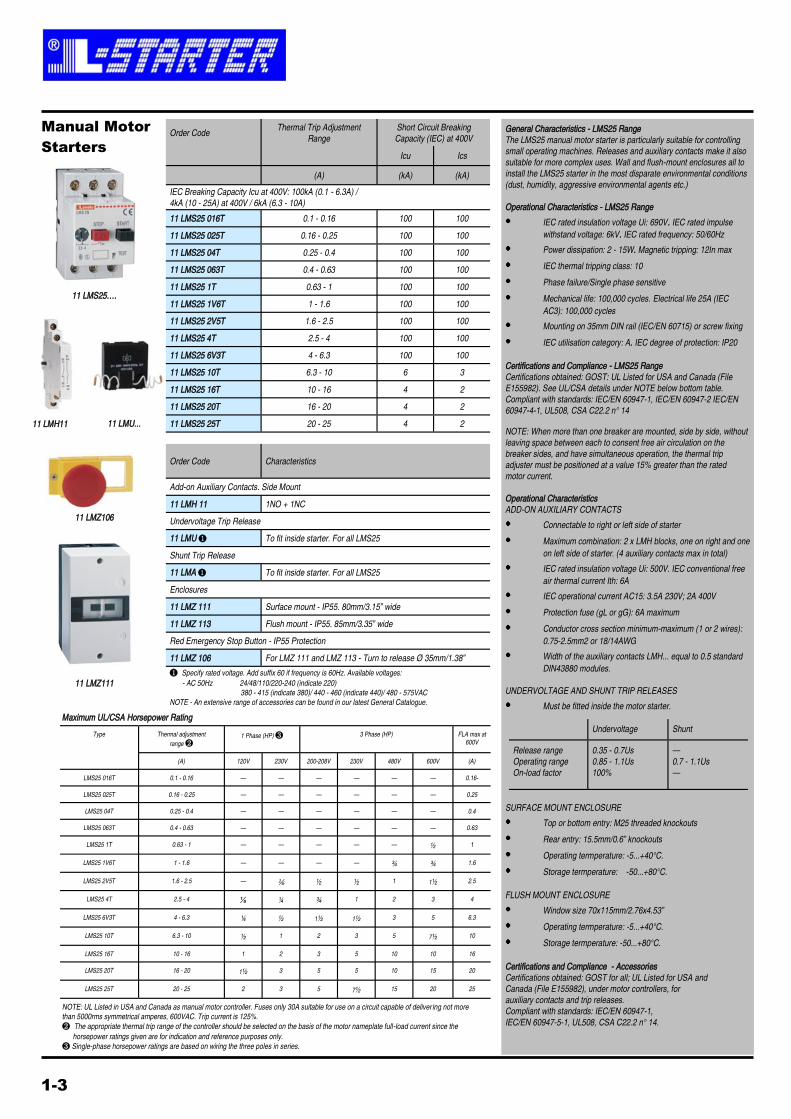
Order Code Thermal Trip Adjustment
Range
Short Circuit Breaking
Capacity (IEC) at 400V
Icu Ics
(A) (kA) (kA)
IEC Breaking Capacity Icu at 400V: 100kA (0.1 - 6.3A) /
4kA (10 - 25A) at 400V / 6kA (6.3 - 10A)
11 LMS25 016T 0.1 - 0.16 100 100
11 LMS25 025T 0.16 - 0.25 100 100
11 LMS25 04T 0.25 - 0.4 100 100
11 LMS25 063T 0.4 - 0.63 100 100
11 LMS25 1T 0.63 - 1 100 100
11 LMS25 1V6T 1 - 1.6 100 100
11 LMS25 2V5T 1.6 - 2.5 100 100
11 LMS25 4T 2.5 - 4 100 100
11 LMS25 6V3T 4 - 6.3 100 100
11 LMS25 10T 6.3 - 10 6 3
11 LMS25 16T 10 - 16 4 2
11 LMS25 20T 16 - 20 4 2
11 LMS25 25T 20 - 25 4 2
Order Code Characteristics
Add-on Auxiliary Contacts. Side Mount
11 LMH 11 1NO + 1NC
Undervoltage Trip Release
11 LMU ❶ To fit inside starter. For all LMS25
Shunt Trip Release
11 LMA ❶ To fit inside starter. For all LMS25
Enclosures
11 LMZ 111 Surface mount - IP55. 80mm/3.15” wide
11 LMZ 113 Flush mount - IP55. 85mm/3.35” wide
Red Emergency Stop Button - IP55 Protection
11 LMZ 106 For LMZ 111 and LMZ 113 - Turn to release Ø 35mm/1.38”
❶ Specify rated voltage. Add suffix 60 if frequency is 60Hz. Available voltages:
- AC 50Hz 24/48/110/220-240 (indicate 220)
380 - 415 (indicate 380)/ 440 - 460 (indicate 440)/ 480 - 575VAC
NOTE - An extensive range of accessories can be found in our latest General Catalogue.
General Characteristics - LMS25 Range
The LMS25 manual motor starter is particularly suitable for controlling
small operating machines. Releases and auxiliary contacts make it also
suitable for more complex uses. Wall and flush-mount enclosures all to
install the LMS25 starter in the most disparate environmental conditions
(dust, humidity, aggressive environmental agents etc.)
Operational Characteristics - LMS25 Range
IEC rated insulation voltage Ui: 690V. IEC rated impulse
withstand voltage: 6kV. IEC rated frequency: 50/60Hz
Power dissipation: 2 - 15W. Magnetic tripping: 12In max
IEC thermal tripping class: 10
Phase failure/Single phase sensitive
Mechanical life: 100,000 cycles. Electrical life 25A (IEC
AC3): 100,000 cycles
Mounting on 35mm DIN rail (IEC/EN 60715) or screw fixing
IEC utilisation category: A. IEC degree of protection: IP20
Certifications and Compliance - LMS25 Range
Certifications obtained: GOST: UL Listed for USA and Canada (File
E155982). See UL/CSA details under NOTE below bottom table.
Compliant with standards: IEC/EN 60947-1, IEC/EN 60947-2 IEC/EN
60947-4-1, UL508, CSA C22.2 n° 14
NOTE: When more than one breaker are mounted, side by side, without
leaving space between each to consent free air circulation on the
breaker sides, and have simultaneous operation, the thermal trip
adjuster must be positioned at a value 15% greater than the rated
motor current.
Operational Characteristics
ADD-ON AUXILIARY CONTACTS
Connectable to right or left side of starter
Maximum combination: 2 x LMH blocks, one on right and one
on left side of starter. (4 auxiliary contacts max in total)
IEC rated insulation voltage Ui: 500V. IEC conventional free
air thermal current Ith: 6A
IEC operational current AC15: 3.5A 230V; 2A 400V
Protection fuse (gL or gG): 6A maximum
Conductor cross section minimum-maximum (1 or 2 wires):
0.75-2.5mm2 or 18/14AWG
Width of the auxiliary contacts LMH... equal to 0.5 standard
DIN43880 modules.
UNDERVOLTAGE AND SHUNT TRIP RELEASES
Must be fitted inside the motor starter.
SURFACE MOUNT ENCLOSURE
Top or bottom entry: M25 threaded knockouts
Rear entry: 15.5mm/0.6” knockouts
Operating termperature: -5...+40°C.
Storage termperature: -50...+80°C.
FLUSH MOUNT ENCLOSURE
Window size 70x115mm/2.76x4.53”
Operating termperature: -5...+40°C.
Storage termperature: -50...+80°C.
Certifications and Compliance - Accessories
Certifications obtained: GOST for all; UL Listed for USA and
Canada (File E155982), under motor controllers, for
auxiliary contacts and trip releases.
Compliant with standards: IEC/EN 60947-1,
IEC/EN 60947-5-1, UL508, CSA C22.2 n° 14.
11 LMS25….
Manual Motor
Starters
1-3
Thermal adjustment
range ❷
1 Phase (HP) ❸ 3 Phase (HP) FLA max at
600V
Type
(A) 120V 230V 200-208V 230V 480V 600V (A)
LMS25 016T 0.1 - 0.16 — — — — — — 0.16-
LMS25 025T 0.16 - 0.25 — — — — — — 0.25
LMS25 04T 0.25 - 0.4 — — — — — — 0.4
LMS25 063T 0.4 - 0.63 — — — — — — 0.63
LMS25 1T 0.63 - 1 — — — — — ½ 1
LMS25 1V6T 1 - 1.6 — — — — ¾ ¾ 1.6
LMS25 2V5T 1.6 - 2.5 — ⅙ ½ ½ 1 1½ 2.5
LMS25 4T 2.5 - 4 ⅛ ¼ ¾ 1 2 3 4
LMS25 6V3T 4 - 6.3 ¼ ½ 1½ 1½ 3 5 6.3
LMS25 10T 6.3 - 10 ½ 1 2 3 5 7½ 10
LMS25 16T 10 - 16 1 2 3 5 10 10 16
LMS25 20T 16 - 20 1½ 3 5 5 10 15 20
LMS25 25T 20 - 25 2 3 5 7½ 15 20 25
Maximum UL/CSA Horsepower Rating
NOTE: UL Listed in USA and Canada as manual motor controller. Fuses only 30A suitable for use on a circuit capable of deliver ing not more
than 5000rms symmetrical amperes, 600VAC. Trip current is 125%.
❷ The appropriate thermal trip range of the controller should be selected on the basis of the motor nameplate full-load current since the
horsepower ratings given are for indication and reference purposes only.
❸ Single-phase horsepower ratings are based on wiring the three poles in series.
Undervoltage Shunt
Release range
Operating range
On-load factor
0.35 - 0.7Us
0.85 - 1.1Us
100%
—
0.7 - 1.1Us
—
11 LMH11
11 LMZ111
11 LMZ106
11 LMU...

Order Code IEC Rated Starter
Current Ie in AC-53b Rated Motor Power
(A) IEC
(kW)
UL/CSA
(HP)
With Integrated By-pass Relay. 110-400VAC Auxiliary Supply.
Three-phase 400VAC Motor Control.
ADXC 012 400 12 5.5 3
ADXC 016 400 16 7.5 7.5
ADXC 025 400 25 11 10
ADXC 032 400 32 15 15
ADXC 037 400 37 18.5 20
ADXC 045 400 45 22 25
We offer an extensive range of soft starters which can be found in our latest General
Catalogue, or our website or contact our sales office for more information.
Current Control
ADXC… gradually increases the current limit at 75% ramp-up time if the motor speed has yet
to reach rated value, to avoid locked rotor state before time elapsing
ADXC…. Adjustments
General Characteristics
ADXC… is a compact type of soft starter, 45mm wide and easy to use,
for three phase squirrel-cage induction motors; soft starts and soft stops
rated motor load currents up to 45A.
It is based on a current limiting starting methodology to limit the
maximum starting current. ADXC… reduces the mechanical load on
motor shafts, gearboxes and drive belts.
Ramp up, ramp down and initial voltage time settings can be
independently adjusted by built-in potentiometers.
Main features are:
For 3ph induction motors up to 22kW / 25HP at 400VAC
Maximum input voltage: 400VAC 50/60Hz
Built-in bypass relay
Wrong phase sequence and over temperature protection
Alarm for wrong phase sequence; line voltage and/or
frequency out of limits (over and undervoltage); overcurrent,
over temperature, irregular ramp up and current flow during
bypass; motor voltage unbalance
Simple setting and installation
2 relay outputs for alarms (NC) and bypass closing
35mm DIN rail mounting (IEC/EN 60715)
Ideal for hydraulic lifts, conveyor belts, compressors, pumps,
hoisting devices, blowers, fans, mixers.
Operational characteristics
Number of controlled phases: 2
Input voltage L1-L2-L3: 220-400VAC -15%...+10%
Frequency range: 50/60Hz ±10% self-configurable
Separate single phase auxiliary power supply A1-A2:
Start command: A1-A2 110…400VAC -15%...+10%
Ramp up time: 1-20 secs, Ramp down time: 0-20 secs
3 x Alarm indication LEDs
Degree of protection: IEC IP20.
Certifications and compliance
Certifications obtained: UL Listed for USA and Canada (cULus – File
E223223) under Solid State Motor Controllers as reduced voltage
starters; EAC and CCC pending completion at time of catalogue print-
ing. Compliant with standards: IEC/EN 60947-1, IEC/EN 60947-4-2, UL
508, CSA C22.2 n°14.
ADXC…..
Order Code Output
Current Output Power Dimensions
W x H x D
(A) (kW) (HP) (mm)
Input: Single phase 200...240VAC
Output: 3-phase 0...240VAC - 0...650Hz (EMC filter built-in)
VE1 02 A240 1.8 0.2 0.25
72 x 131 x 139 VE1 04 A240 2.6 0.4 0.54
VE1 07 A240 4.3 0.75 1
VE1 15 A240 7.5 1.5 2 118 x 131 x 147
VE1 22 A240 10.5 2.2 3
NOTE: 5cm minimum required for side by side installations.
CD software and instruction manual included.
Order Code Description
Accessories
VEX C00 RS485 (RJ45) - PC (USB) Connection Cable
General Characteristics
Working temperature: -10…+40°C (50°C with fan or 20%
current de-rating)
Relative humidity: 95%
Output frequency range: 0...650Hz
Built-in EMC filter 1° Environment, Category C2 (EN61800)
Group 1, Class A (EN55011)
Control mode: V/f (6 fixed curves, 1 programmable). Torque
boost
Digital input/outputs: 5 programmable inputs (pNp),
1 programmable output (250VAC/1A - 30VDC/1A)
Analogue input/outputs: 1 input - 0...10V, 0/4...20mA
1 output - 0...10V
Output frequency setting: Front panel (▲▼ keys or
potentiometer), Digital inputs (8 selections, with independent
acceleration/deceleration times), Communication protocol
Motor start and stop: Front panel (RUN and STOP keys),
Digital inputs (2 or 3 wire control)
Built-in communication port: RS485 (RJ45), modbus RTU
and modbus ASCII
IP protection: IP20
AC Motor
Drives
VE1
1-4
Further technical data is available on our website www.Lovato.co.uk or contact our sales office.
We offer an extensive range of AC motor drives which can be found in our latest General
Catalogue or contact our sales office for more information.
Soft
Starters
A Initial voltage : 0-85% of motor control power
B Ramp Up Time: 1-20 seconds, Initial to max load voltage time.
C Ramp Down Time: 0-20 seconds. Max to no load voltage time.

Order Code
IEC Operating
Current Ith
AC1 (≤ 40°C)
(A)
Ie (AC3)
≤ 440V at
≤ 55°C
(A)
Incorporated
Auxiliary
Contacts
Type of
Terminal
3 Pole Mini-contactors with AC Control Circuit
11BG09 10 A*** 20 9 1 N/O Clamp-screw
11BG12 10 A*** 20 12 1 N/O Clamp-screw
3 Pole Contactors with AC Control Circuit
BF09 10 A*** 25 9 1 N/O Clamp-screw
BF12 10 A*** 28 12 1 N/O Clamp-screw
BF18 10 A*** 32 18 1 N/O Clamp-screw
BF25 10 A*** 32 25 1 N/O Clamp-screw
BF26 00 A*** 45 26 — Clamp-screw
BF32 00 A*** 56 32 — Clamp-screw
BF38 00 A*** 60 38 — Clamp-screw
11 BF50 00*** 90 50 — Allen-screw
11 BF65 00*** 110 65 — Allen-screw
11 BF80 00*** 125 80 — Allen-screw
11 BF95 00*** 125 95 — Allen-screw
11 BF110 00*** 125 110 — Allen-screw
*** Complete with AC coil voltage 50/60Hz - 024, 110, 230, 400V
Add-on Blocks for BG Type Mini-contactors
11 BGX10 11 Screw Type Auxiliary Contact 1NO + 1NC
11 BGX10 02 Screw Type Auxiliary Contact 2NC
11 BGX10 20 Screw Type Auxiliary Contact 2NO
11 BGX 5000 Mechanical Interlock for BG Contactors
Add-on Blocks for BF Type Contactors
BFX10 11 Screw Type Auxiliary Contact 1NO + 1NC (front centre mount)
BFX10 02 Screw Type Auxiliary Contact 2NC (front centre mount)
BFX10 20 Screw Type Auxiliary Contact 2NO (front centre mount)
BFX10 22 Screw Type Auxiliary Contact 2NO + 2NC (front centre mount)
BFX 5000 Mechanical Interlock for BF09 to BF38 Contactors
11 G2692 Mechanical Interlock for BF50 - BF110 Contactors
Note - Four pole contactors and an extensive range of accessories can be found in our latest
General Catalogue from www.Lovato.co.uk or contact our sales office for more information.
General Characteristics and Certifications - BG Mini-contactors
Operating temperature: -40...+60oC
Storage temperature: -55...+70oC
Quick connect - snap on accessory mounting
Distinct contact status indication
DC versions also available
Screw or 35mm Din rail fixing (IEC/EN 60715)
Certificates - UL, GOST, CCC
General Characteristics and Certifications - BF09 to BF38 Contactors
Operating temperature: -50...+70oC
Storage temperature: -60...+80oC
Quick connect - snap on accessory mounting
Four terminal coil
DC Versions also available
Screw or 35mm Din rail fixing (IEC/EN 60715)
Certifications - UL, CSA (Canada only), GOST, CCC, RINA
General Characteristics and Certifications - BF50 to BF110 Contactors
Operating temperature: -50...+70oC
Storage temperature: -60...+80oC
Quick connect - snap on accessory mounting
DC Versions also available
Screw or 35mm and 75mm Din rail fixing (IEC/EN 60715)
Certifications - UL, CSA (Canada only), GOST, CCC, RINA
(except BF110), LROS (except BF110)
All contactors are compliant with standards - IEC/EN 60947-1, IEC/EN
60947-4-1, UL508, CSA C22.2 n° 14.
BG Contactors
BF09A to BF25A
Three-pole
Contactors
Operational Characteristics
DC powered magnetic core system assuring silent
operation and noise damping during the control phase
Overvoltage protection circuit and voltage peak limitation
of the magnetic core
Equipped with 2 or 4 closing contacts of equal capacity
permitting use in power or auxiliary circuits
Operation flag indicator
Fast mounting.
Noise level: Closed contactor ≤20dB
Making/breaking operation ≤50dB
IEC degree of protection: IP20
Mounting on 35mm DIN rail (IEC/EN 60175).
Certifications and compliance
Compliant with standards: IEC/EN 60947-1, 60947-4-1,
60947-5-1 and 61095
Modular
Contactors
1-5
BF50 - BF110
CN40…, CN20...
BFX1011
Order Code IEC Rated Current
Ith in AC-1 Rated Motor
Power Contact Configuration
(A) IEC
(kW) N.O. N.C.
Two Pole 220-230V AC (For 24V AC/DC version change CN…….220 code to CN……...024)
CN20 11 220 20 - - 1 1
CN20 20 220 20 - - 2 0
Three or Four Pole 220-230V AC (For 24V AC/DC version change CN…….220 code to CN……...024)
CN25 10 220 25 4.0 4 0
CN25 01 220 25 4.0 3 1
CN40 10 220 40 11.0 4 0
CN40 01 220 40 11.0 3 1
CN63 10 220 63 15.0 4 0
CN63 01 220 63 15.0 3 1
Auxiliary Contacts (one max per contactor)
CNH 11 6 - - 1 1
CNH 20 6 - - 2 0

Order Code Description
1 Gang Plastic Enclosure Grey Cover
S1P10 Standard Green PB "I" (START) c/w 1NO contact
S1P01 Standard Red PB "O" (STOP) c/w 1NC contact
S1P33 Double Touch PB "I/O" (START/STOP) c/w 1NO & 1NC contacts
S1PK02 Key Switch 2 pos "I-O" c/w 1NO contact
S1PK05 Key Switch 3 pos "I-O-II" c/w 2NO contact
S1PSW7 Selector Switch 2 pos "I-O" c/w 1NO contact
S1PSW9 Selector Switch 3 pos "I-O-II" c/w 2NO contact
1 Gang Plastic Enclosure Yellow Cover
S1PY71 40mm Mushroom Twist Reset (STOP) c/w 1NC contact
S1PY81 40mm Mushroom Key Reset (STOP) c/w 1NC contact
S1PY91 40mm Mushroom Twist Reset (EMERGENCY STOP) c/w 1NC contact
2 Gang Plastic Enclosure Grey Cover
S2P1001 Standard Green "I" PB's (START/STOP) c/w 1NO & 1NC contacts
S2P1071 Standard Green "I" & 40mm Mushroom Twist Release PB's
(START/STOP) c/w 1NO & 1NC contacts
S2P1091 Standard Green "I" & 40mm Mushroom Twist Release EN418 PB's
(START/EMERGENCY STOP) c/w 1NO & 1NC contacts
3 Gang Plastic Enclosure Grey Cover
S3P101110 2x Standard Black "↑" & 1x Standard Red "O" PB's (FWD/STOP/REV)
S3P107110 2x Standard Black "↑" & 1x 40mm Mushroom Twist Release PB's
S3P109110 2x Standard Black "↑" & 1x 40mm Mushroom Twist Release EN418
1 Gang Stainless Steel Enclosure
S1S10 Standard Green PB "I" (START) c/w 1NO contact
S1S01 Standard Red PB "O" (STOP) c/w 1NC contact
S1S33 Double Touch PB "I/O" (START/STOP) c/w 1NO & 1NC contacts
S1SK02 Key Switch 2 pos "I-O" c/w 1NO contact
S1SK05 Key Switch 3 pos "I-O-II" c/w 2NO contact
S1SW7 Selector Switch 2 pos "I-O" c/w 1NO contact
S1SSW9 Selector Switch 3 pos "I-O-II" c/w 2NO contact
S1S71 40mm Mushroom Twist Reset (STOP) c/w 1NC contact
S1S81 40mm Mushroom Key Reset (STOP) c/w 1NC contact
S1S91 40mm Mushroom Twist Reset (EMERGENCY STOP) c/w 1NC contact
2 Gang Stainless Steel Enclosure
S2S1001 Standard Green "I" PB's (START/STOP) c/w 1NO & 1NC contacts
S2S1071 Standard Green "I" & 40mm Mushroom Twist Release PB's
S2S1091 Standard Green "I" & 40mm Mushroom Twist Release EN418 PB's
General Characteristics
Operating temperature: -20...+55oC (RF9)
Operating temperature: -25...+60oC (RF38)
Storage temperature: -50...+70oC
Degree of protection (Plastic): IP66, IP67, IP69K
Degree of protection (Stainless): IP65
Base mounted contact blocks (plastic enclosures)
Any combination of up to 6 gang stations available upon
request and subject to availability
Certifications and compliance
Compliant with standards: IEC/EN 60947-1 and IEC/EN
60947-4-1
S1PY91
S2P1001
S1S10
S1S91
1-6
S1P10
Enclosed
Control
Stations

Order Code
Dimensions
H x W x D
(mm)
IEC Conventional Free
Air Thermal Current Ith
AC21A (≤690V)
(A)
3 Pole Switch Disconnector with Red/Yellow Handle in Polycarbonate Enclosure
GAZ016 16
159 x 100 x 97 GAZ025 25
GAZ032 32
GAZ040 40
GAZ063* 63
280 x 220 x 170 GAZ080* 80
GAZ100* 100
GAZ125* 125
*GAZ063-GAZ125 supplied without earth terminals
3 Pole Switch Disconnector with Red/Yellow Handle in Satin Stainless Steel Enclosure
GAZS016 16
170 x 100 x 100 GAZS025 25
GAZS032 32
GAZS040 40
GAZS063 63
285 x 185 x 130 GAZS080 80
GAZS100 100
GAZS125 125
Switched Fourth Pole Add-On
GAX42040A 16 - 40 Fits GAZ(S)016 - GAZ(S)040
GAX42063A 63 Fits GAZ(S)063
GAX42080A 80 Fits GAZ(S)080
GAX42100A 100 Fits GAZ(S)100
GAX42125A 125 Fits GAZ(S)125
Add-On Blocks
GAX1011A 1NO+1NC Auxiliary contact block fits all types
GAX31A Neutral Terminal for GAZ(S)016 - GAZ(S)040 Types
GAX32A Neutral Terminal for GAZ(S)063 - GAZ(S)125 Types
GAX33A Earth Terminal for GAZ(S)016 - GAZ(S)040 Types
GAX34A Earth Terminal for GAZ(S)063 - GAZ(S)125 Types
Operational Characteristics -
Operating temperature: -25...+60oC
Storage temperature: -40...+70oC
Chemical resistant polycarbonate (GAZ... or stainless steel
enclosure (GAZS…)
Degree of protection: IP65
Padlockable handle
Add fourth pole GAX42…… for four pole version
Cable entries:
GAZ016 - GAZ040: 4 x M20 / M25 dual knockouts
GAZ063 - GAZ125 and GAZS016 - GAZS125
smooth walls to be drilled by installer
Cable capacities
GAZ(S)016 - GAZ(S)040 = 16mm2
GAZ(S)063 - GAZ(S)125 = 50mm2
Certifications and compliance - Starters
Compliant with standards: IEC/EN 60947-3 and
IEC/EN 60947-1
GAZ…..
GAZS….
GAX42….
Enclosed
Switch
Disconnectors
Order Code
Current Rating
Ith
(A)
Dimensions
H x W x D
(mm)
Switch Disconnector for DC Switching and Solar Applications
GAZ040DT4B 40 159 x 100 x 97
GAZ080DT4B 80 280 x 220 x 170
GAZ125DT4B 125
Operational Characteristics
Insulated polycarbonate enclosure
Operating temperature: -25...+60oC
Storage temperature: -40...+70oC
Degree of protection: IP65
Padlockable handle
IEC Rated insulation voltage Ui: 1000VDC
Certifications and compliance - Starters
Compliant with standards: IEC/EN 60715
Rated operational current Ie DC21B for devices at operational voltages:
GAX1011A….
Operating Voltage GAZ040DT4B GAZ080DT4B GAZ125DT4B
Up to 48VDC 40A 80A 125A
Up to 110VDC 35A 70A 120A
Up to 400VDC 35A 40A 64A
Up to 500VDC 32A 40A 56A
Up to 600VDC 20A 30A 40A
Up to 700VDC 15A 18A 20A
Up to 800VDC 15A 18A 20A
DC Switch
Disconnectors
For Solar
Applications
GAZ040DT4B
1-7

Order Code
IEC Conventional Free
Air Thermal Current Ith
AC23A (≤690V)
(A)
Dimensions inc Handle
H x W x D
(mm)
3 Pole Switch Disconnector with Red/Yellow Handle in Steel Enclosure with fitted neutral
disconnect link
GEZ0063 63 300 x 300 x 246
GEZ0100 100
GEZ0160 160 400 x 300 x 246
GEZ0250 250 500 x 400 x 295
GEZ0400 400
GEZ0630 630 700 x 500 x 310
3 Pole Fuse Switch with Red/Yellow handle in steel enclosure with fitted neutral link and
fuses
GEZ0063N 63 500 x 400 x 245
GEZ0100N 100
GEZ0160N 160 500 x 400 x 295
GEZ0250N 250 800 x 600 x 310
GEZ0400N 400
GEZ0630N 630 1000 x 600 x 360
4 Pole Changeover Switches with Black handle in steel enclosure
GEZ0063ET4 63 300 x 300 x 235
GEZ0100ET4 100
GEZ0160ET4 160 400 x 300 x 260
GEZ0250ET4 250 500 x 400 x 260
GEZ0400ET4 400 500 x 400 x 310
GEZ0630ET4 630 700 x 500 x 310
Operational Characteristics
Operating temperature: -25...+60oC
Storage temperature: -40...+70oC
Ratings up to 630A
Pressed steel enclosure: IP65 in RAL7035
Padlockable handles
Generous wiring space
Supplied with al cable shrouds
Earth link to door fitted
Disconnectable neutral link with shroud*
Supplied with NH Fuses (NFC for 63A-100A)**
Standard replaceable components
Gland plate fitted to bottom
Certifications and compliance
Compliant with standards: IEC/EN 60947-3 and
IEC/EN 60947-1
* Not fitted to changeover switches
** Fused switches only
GEZ…. GEZ….N
Steel Enclosed
Switch
Disconnectors,
Switchfuses,
Changeover
Switches
1-8
GEZ….E
Order Code
Current Rating
Ith
(A)
Dimensions
H x W x D
(mm)
IP65 Switchfuse Isolator supplied with 10x38mm gG Fuses
GAZ020F 20 234 x 110 x 97
GAZ032F 32
Enclosed
Switchfuse
Isolators
GAZ….F
Operational Characteristics
Insulated polycarbonate enclosure: IP65
Operating temperature: -25...+60oC
Storage temperature: -40...+70oC
Includes switched fourth pole & padlockable handle
For use with 10x38 gG fuse types
Cable entries: 4 x M20 / M25 dual knockouts
Certifications and compliance
Compliant with standards: IEC/EN 60947-1 and
IEC/EN 60947-3
Standard Lovato Switches
& Fuse Switches
Fully Shrouded
Neutral Link
Door Earth Link
Gland Plate

Current
Rating AC1
(A)
Dimensions
H x W x D
(mm)
Order Code
3 Pole Changeover Switch with Black Handle in Polycarbonate Enclosure—centre off
GX16 53 P 16 90 x 90
GX20 53 P 20 90 x 90
GX32 53 P 32 110 x 110
GX40 53 P 40 110 x 110
4 Pole Changeover Switch with Black Handle in Polycarbonate Enclosure—centre off
GX16 75 P 16 90 x 90
GX20 75 P 20 90 x 90
GX32 75 P 32 110 x 110
GX40 75 P 40 110 x 110
Operational Characteristics
Insulated plastic enclosure
Operating temperature: -25...+55oC
Storage temperature: -40...+70oC
Degree of protection: IP65
Top and bottom cable entry: 4 PG16 threaded knockouts for
90 x 90mm types and PG21 for 110 x 100mm types.
Certifications and compliance
Certifications obtained: GOST
Compliant with standards: IEC/EN 60947-1,
IEC/EN 60947-3 , IEC/EN 60947-5-1, IEC/EN 61058-1
GX….P
Enclosed
Changeover
Switches
1-9
Order Code
Current
Rating AC1
(A)
Front Plate Size
(mm)
Front Mount - One pole - 1 Wafer - ON/OFF Switches
GX16 90 U 16 48
GX20 90 U 20 48
GX32 90 U 32 65
GX40 90 U 40 65
Front Mount - Two pole - 1 Wafer - ON/OFF Switches
GX16 91 U 16 48
GX20 91 U 20 48
GX32 91 U 32 65
GX40 91 U 40 65
Front Mount - Three pole - 2 Wafers - ON/OFF Switches
GX16 10 U 16 48
GX20 10 U 20 48
GX32 10 U 32 65
GX40 10 U 40 65
Note - Our extensive range of rotary cam switches can be found in our General Catalogue
available on request from our sales office
GX….U
Rotary Cam
Switches
ON/OFF
Operational Characteristics
Operating temperature: -25...+55oC
Storage temperature: -40...+70oC
IEC 16 to 40A conventional free air thermal current Ith
ratings
IEC IP65 front degree of protection; IEC IP20 protection of
contacts
Rotation angles: 30° , 45° , 60° and 90°
Certifications and compliance
Certifications obtained: GOST; UL Listed for USA and
Canada (File E155982) as Manual Motor Controllers
Compliant with standards: IEC/EN 60947-1,
IEC/EN 60947-3 , IEC/EN 60947-5-1, IEC/EN 61058-1,
UL508, CSA C22.2 n° 14
Example of U Version Switch Mounting
Operational Characteristics
Insulated polycarbonate enclosure
Operating temperature: -25...+60oC
Storage temperature: -40...+70oC
Degree of protection: IP65
M0N, M1N and M2N have moulded din rail mount in base of
enclosure and have external fixings to maintain IP rating
M3N has a hinged lid and requires mounting plate MX30 for
fitting of devices
Certifications and compliance
Compliant with standards: IEC/EN 60947-1 and IEC/EN
60947-4-1
Empty
Enclosures
* For thermal overload relay (RF952) to use with BF38A contactor,
please contact our customer services.
M0N
M3N
Order Code
Suitable for LOVA-
TO
Contactor Type
(to be ordered
separately)
Dimensions
H x W x D (mm)
Suitable for LOVA-
TO Thermal Relay
Type
(to be ordered
separately)
M0N
BG06
BG09
BG12
184 x 88 x 119.5 RF9
M1N
BF09A
BF12A
BF18A
202 x 88 x 134.5 RF38
M2N
BF25A
BF26A
BF32A
234 x 110 x 148.5 RF38
M24N (inc mount plate) All Above 210 x 175 x 98.5
M25N (inc mount plate) All Above + BF38 RF38 210 x 175 x 158.5
M3N
BF38A
BF50, BF65
BF80, BF95
BF110
280 x 220 x 170 RF953 *
Metal Mounting Plate for M3N Enclosure
MX30 — 185W x 240H mm —

Order Code Description
Limit Switch body dimensions to EN50047 — order operating head separately below
KXCBS11 Plastic body, one bottom M20 cable entry, 1NO+1NC snap action
KXCMS11 Metal body, one bottom M20 cable entry, 1NO+1NC snap action
KXCCS11 Plastic body, two side M20 cable entry, 1NO+1NC snap action
KXCNS11 Metal body, two side M20 cable entry, 1NO+1NC snap action
Operating Heads to Fit KX… Limit Switch Bodies
KXA A1 Top push rod plunger
KXA B1 Plastic top roller push plunger
KXA B2 Metal top roller push plunger
KXA C1 Plastic roller centre push lever
KXA C2 Metal roller centre push lever
KXA D1 Plastic roller side push lever
KXA D2 Metal roller side push lever
KXA E1 Plastic roller lever plunger
KXA E2 Metal roller lever plunger
KXA E3 Rubber Ø50x10mm roller lever plunger
KXA F1 Adjustable plastic roller lever Ø19x5mm
KXA F2 Adjustable metal roller lever Ø19x5mm
KXA F3 Adjustable rubber Ø50x10mm roller lever
KXA F4 Adjustable offset rubber Ø50x10mm roller lever
KXA H1 Ceramic rod lever
KXA L1 Adjustable plastic rod lever
KXA L2 Adjustable stainless steel rod lever
KXA M1 Flexible wobble stick
KXA M2 Semi-rigid wobble stick
General Characteristics
The KX C... bodies, complete with auxiliary contacts, can be coupled
with the KX A... operating heads, to obtain complete limit switches in the
required configurations. The body cover is hinged at the bottom and
removable to have the best access. Each body includes the innovative
locking bayonet mechanism of the operating head. Plastic and metal
types are available.
The heads are made of metal and warrant sturdiness and operating
reliability in all conditions. The shape of the coupling section with the
body of the K series switches permits to orient the head in any 45°
angle position while the initial lever and rod position can be adjusted
360° at 15° angle positions. The head fixing to the body is achieved by
the innovative locking bayonet mechanism so
there is no need of tools.
Operational characteristics
Mechanical life: >10 million cycles
IEC thermal current Ith: 10A
IEC rated insulation voltage Ui:
690VAC for KX CB-KX CC types
440VAC for KX CM-KX CN types
KX CB-KX CC types -
Self-extinguishing double-insulation polymer thermoplastic
KX CM-KX CN types - Aluminium-zinc alloy
Cable entry: M20 standard supplied
Operating head fixing: Locking bayonet insert
Cable connection: Self-releasing screw terminal
Conductor section: 1 or 2 2.5mm2 max / 16-14 AWG
• Operating temperature: -25 ... +70°C
• Storage temperature: -40 ... +70°C
• IEC degree of protection: IP65 for body housing.
Certifications and compliance
Certifications obtained: EAC for all, UL Listed for US and Canada (File
E93601), as Auxiliary Devices for KX C... body types only. UL Recog-
nized for USA and Canada (cURus - File E93601) as component -
Comply with standards: EN50047, IEC/EN 60947-1,
General characteristics
The KG and KR foot switches are used to control machinery and other
equipment, leaving the operator’s hands free to do other functions.
Thermoplastic or metal version
Versions complete with or without pedal protection cover
The cover assures protection against accidental operation,
due to sudden tool or heavy material dropping on switch.
Versions with safety lever; The safety mechanism prevents
unintentional foot switch activation and excludes the pedal
pressing if the operator’s foot is not completely in place. Operational characteristics
Mechanical life: >10 million cycles
Conventional thermal current Ith: 10A
Designation to IEC/EN 60947-5-1:
Class II insulation (KG types only)
Operating temperature: -25 ... +70°C
1-10
Limit
Switches
KXCBS11
KXCMS11
KXCCS11
KXCNS11
KXA1
KXB...
KXC...
KXD...
KXE...
KXE3
KXF... KXF4 KXH1 KXL... KXM1 KXM2
Order Code Description
Plastic Body Foot Switch M20 Cable Entry
KG100 S11 Open foot switch with 1NO+1NC action contacts
KG200 S11 Foot switch with 1NO+1NC action contacts—with cover
KG110 S11 Open foot switch with 1NO+1NC action contacts c/w safety lever
KG210 S11 Foot switch with 1NO+1NC action contact c/w cover and safety lever
KG120 S11 Open foot switch with 1NO+1NC action contacts c/w actuator lock
KG220 S11 Foot switch with 1NO+1NC action contacts c/w cover and actuator lock
Metal Body Foot Switch M20 Cable Entry
KR100 S11 Open foot switch with 1NO+1NC action contacts
KR200 S11 Foot switch with 1NO+1NC action contacts—with cover
KR110 S11 Open foot switch with 1NO+1NC action contacts c/w safety lever
KR210 S11 Foot switch with 1NO+1NC action contact c/w cover and safety lever
KR120 S11 Open foot switch with 1NO+1NC action contacts c/w actuator lock
KR220 S11 Foot switch with 1NO+1NC action contacts c/w cover and actuator lock
Foot
Switches
KG100S11
KG210S11
KR210S11
See General Catalogue for the full range of limit, micro and foot
switches or online at www.lovato.co.uk
See General Catalogue for the full range of foot switches or online at www.lovato.co.uk
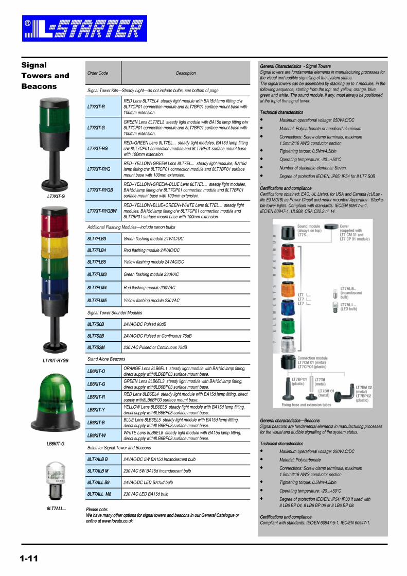
General characteristics—Beacons
Signal beacons are fundamental elements in manufacturing processes
for the visual and audible signalling of the system status.
Technical characteristics
Maximum operational voltage: 250VAC/DC
Material: Polycarbonate
Connections: Screw clamp terminals, maximum
1.5mm2/16 AWG conductor section
Tightening torque: 0.5Nm/4.5lbin
Operating temperature: -20...+50°C
Degree of protection IEC/EN: IP54; IP30 if used with
8 LB6 BP 04, 8 LB6 BP 06 or 8 LB6 BP 08.
Certifications and compliance
Compliant with standards: IEC/EN 60947-5-1, IEC/EN 60947-1.
Order Code Description
Signal Tower Kits—Steady Light—do not include bulbs, see bottom of page
LT7KIT-R
RED Lens 8LT7EL4 steady light module with BA15d lamp fitting c/w
8LT7CP01 connection module and 8LT7BP01 surface mount base with
100mm extension.
LT7KIT-G
GREEN Lens 8LT7EL3 steady light module with BA15d lamp fitting c/w
8LT7CP01 connection module and 8LT7BP01 surface mount base with
100mm extension.
LT7KIT-RG
RED+GREEN Lens 8LT7EL... steady light modules, BA15d lamp fitting
c/w 8LT7CP01 connection module and 8LT7BP01 surface mount base
with 100mm extension.
LT7KIT-RYG
RED+YELLOW+GREEN Lens 8LT7EL... steady light modules, BA15d
lamp fitting c/w 8LT7CP01 connection module and 8LT7BP01 surface
mount base with 100mm extension.
LT7KIT-RYGB
RED+YELLOW+GREEN+BLUE Lens 8LT7EL... steady light modules,
BA15d lamp fitting c/w 8LT7CP01 connection module and 8LT7BP01
surface mount base with 100mm extension.
LT7KIT-RYGBW
RED+YELLOW+BLUE+GREEN+WHITE Lens 8LT7EL... steady light
modules, BA15d lamp fitting c/w 8LT7CP01 connection module and
8LT7BP01 surface mount base with 100mm extension.
Additional Flashing Modules—include xenon bulbs
8LT7FLB3 Green flashing module 24VAC/DC
8LT7FLB4 Red flashing module 24VAC/DC
8LT7FLB5 Yellow flashing module 24VAC/DC
8LT7FLM3 Green flashing module 230VAC
8LT7FLM4 Red flashing module 230VAC
8LT7FLM5 Yellow flashing module 230VAC
Signal Tower Sounder Modules
8LT7S0B 24VAC/DC Pulsed 90dB
8LT7S2B 24VAC/DC Pulsed or Continuous 75dB
8LT7S2M 230VAC Pulsed or Continuous 75dB
Stand Alone Beacons
LB6KIT-O ORANGE Lens 8LB6EL1 steady light module with BA15d lamp fitting,
direct supply with8LB6BP03 surface mount base.
LB6KIT-G GREEN Lens 8LB6EL3 steady light module with BA15d lamp fitting,
direct supply with8LB6BP03 surface mount base.
LB6KIT-R RED Lens 8LB6EL4 steady light module with BA15d lamp fitting, direct
supply with8LB6BP03 surface mount base.
LB6KIT-Y YELLOW Lens 8LB6EL5 steady light module with BA15d lamp fitting,
direct supply with8LB6BP03 surface mount base.
LB6KIT-B BLUE Lens 8LB6EL5 steady light module with BA15d lamp fitting,
direct supply with8LB6BP03 surface mount base.
LB6KIT-W WHITE Lens 8LB6EL8 steady light module with BA15d lamp fitting,
direct supply with8LB6BP03 surface mount base.
Bulbs for Signal Tower and Beacons
8LT7ALB B 24VAC/DC 5W BA15d Incandescent bulb
8LT7ALB M 230VAC 5W BA15d Incandescent bulb
8LT7ALL B8 24VAC/DC LED BA15d bulb
8LT7ALL M8 230VAC LED BA15d bulb
General Characteristics - Signal Towers
Signal towers are fundamental elements in manufacturing processes for
the visual and audible signalling of the system status.
The signal towers can be assembled by stacking up to 7 modules, in the
following sequence, starting from the top: red, yellow, orange, blue,
green and white. The sound module, if any, must always be positioned
at the top of the signal tower.
Technical characteristics
Maximum operational voltage: 250VAC/DC
Material: Polycarbonate or anodised aluminium
Connections: Screw clamp terminals, maximum
1.5mm2/16 AWG conductor section
Tightening torque: 0.5Nm/4.5lbin
Operating temperature: -20...+50°C
Number of stackable elements: Seven.
Degree of protection IEC/EN: IP65; IP54 for 8 LT7 S0B
.
Certifications and compliance
Certifications obtained: EAC, UL Listed, for USA and Canada (cULus -
file E318016) as Power Circuit and motor-mounted Apparatus - Stacka-
ble tower lights. Compliant with standards: IEC/EN 60947-5-1,
IEC/EN 60947-1, UL508, CSA C22.2 n° 14.
LT7KIT-RYGB
LB6KIT-G
8LT7ALL...
Signal
Towers and
Beacons
LT7KIT-G
Please note:
We have many other options for signal towers and beacons in our General Catalogue or
online at www.lovato.co.uk
1-11
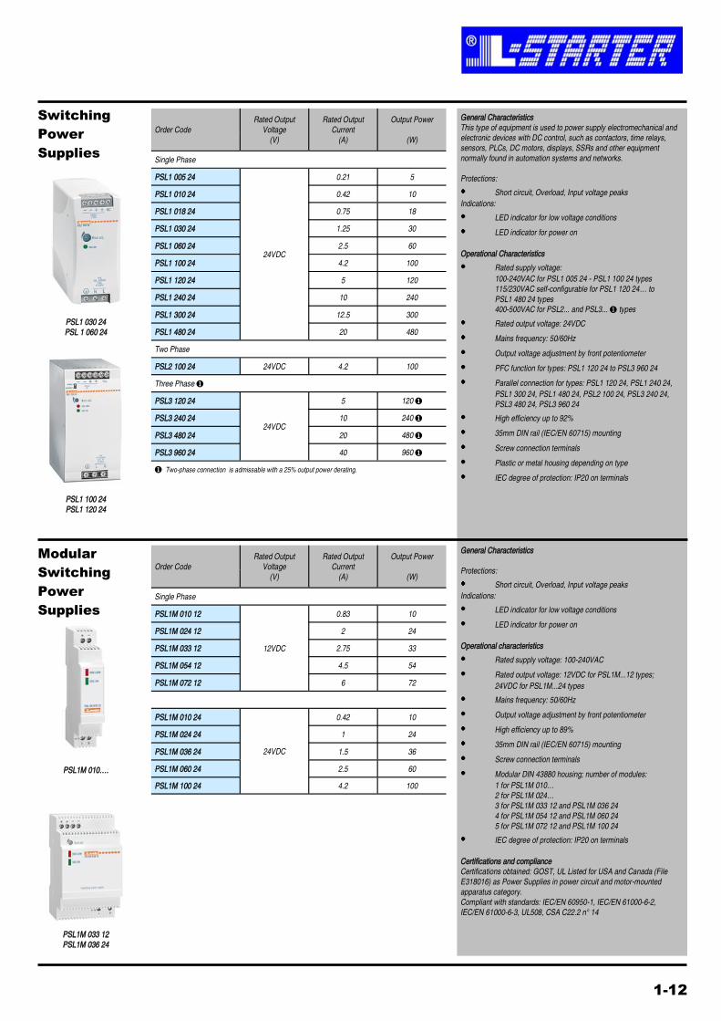
Order Code
Rated Output
Voltage
(V)
Rated Output
Current
(A)
Output Power
(W)
Single Phase
PSL1 005 24
24VDC
0.21 5
PSL1 010 24 0.42 10
PSL1 018 24 0.75 18
PSL1 030 24 1.25 30
PSL1 060 24 2.5 60
PSL1 100 24 4.2 100
PSL1 120 24 5 120
PSL1 240 24 10 240
PSL1 300 24 12.5 300
PSL1 480 24 20 480
Two Phase
PSL2 100 24 24VDC 4.2 100
Three Phase ❶
PSL3 120 24
24VDC
5 120 ❶
PSL3 240 24 10 240 ❶
PSL3 480 24 20 480 ❶
PSL3 960 24 40 960 ❶
❶ Two-phase connection is admissable with a 25% output power derating.
General Characteristics
This type of equipment is used to power supply electromechanical and
electronic devices with DC control, such as contactors, time relays,
sensors, PLCs, DC motors, displays, SSRs and other equipment
normally found in automation systems and networks.
Protections:
Short circuit, Overload, Input voltage peaks
Indications:
LED indicator for low voltage conditions
LED indicator for power on
Operational Characteristics
Rated supply voltage:
100-240VAC for PSL1 005 24 - PSL1 100 24 types
115/230VAC self-configurable for PSL1 120 24… to
PSL1 480 24 types
400-500VAC for PSL2... and PSL3... ❶ types
Rated output voltage: 24VDC
Mains frequency: 50/60Hz
Output voltage adjustment by front potentiometer
PFC function for types: PSL1 120 24 to PSL3 960 24
Parallel connection for types: PSL1 120 24, PSL1 240 24,
PSL1 300 24, PSL1 480 24, PSL2 100 24, PSL3 240 24,
PSL3 480 24, PSL3 960 24
High efficiency up to 92%
35mm DIN rail (IEC/EN 60715) mounting
Screw connection terminals
Plastic or metal housing depending on type
IEC degree of protection: IP20 on terminals
PSL1 030 24
PSL 1 060 24
Switching
Power
Supplies
General Characteristics
Protections:
Short circuit, Overload, Input voltage peaks
Indications:
LED indicator for low voltage conditions
LED indicator for power on
Operational characteristics
Rated supply voltage: 100-240VAC
Rated output voltage: 12VDC for PSL1M...12 types;
24VDC for PSL1M...24 types
Mains frequency: 50/60Hz
Output voltage adjustment by front potentiometer
High efficiency up to 89%
35mm DIN rail (IEC/EN 60715) mounting
Screw connection terminals
Modular DIN 43880 housing; number of modules:
1 for PSL1M 010…
2 for PSL1M 024…
3 for PSL1M 033 12 and PSL1M 036 24
4 for PSL1M 054 12 and PSL1M 060 24
5 for PSL1M 072 12 and PSL1M 100 24
IEC degree of protection: IP20 on terminals
Certifications and compliance
Certifications obtained: GOST, UL Listed for USA and Canada (File
E318016) as Power Supplies in power circuit and motor-mounted
apparatus category.
Compliant with standards: IEC/EN 60950-1, IEC/EN 61000-6-2,
IEC/EN 61000-6-3, UL508, CSA C22.2 n° 14
Modular
Switching
Power
Supplies
PSL1 100 24
PSL1 120 24
Order Code
Rated Output
Voltage
(V)
Rated Output
Current
(A)
Output Power
(W)
Single Phase
PSL1M 010 12
12VDC
0.83 10
PSL1M 024 12 2 24
PSL1M 033 12 2.75 33
PSL1M 054 12 4.5 54
PSL1M 072 12 6 72
PSL1M 010 24 0.42 10
24VDC
PSL1M 024 24 1 24
PSL1M 036 24 1.5 36
PSL1M 060 24 2.5 60
PSL1M 100 24 4.2 100
PSL1M 010….
PSL1M 033 12
PSL1M 036 24
1-12
2-1
Order Code Rated
Cable Size
Current
Rating
Terminal
Pitch
Pack
Quantity
(mm) (A) (mm)
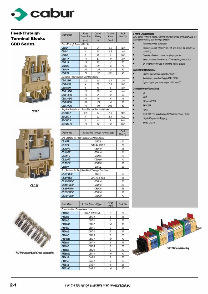
Feed-Through Terminal Blocks
CBD.2 2.5 24 5.5 120
CBD.4 4 32 6.5 100
CBD.6 6 41 8 100
CBD.10 10 57 10 100
CBD.16 16 76 12 50
CBD.35 35 101 16 75
CBD.50 50 125 18 50
CBD.70 70 192 20.5 40
Ex(i) Blue Feed-Through Terminal Blocks
CBD.2EXI 2.5 24 5.5 120
CBD.4EXI 4 32 6.5 100
CBD.6EXI 6 41 8 100
CBD.10EXI 10 57 10 100
CBD.16EXI 16 76 12 50
CBD.35EXI 35 101 16 75
CBD.50EXI 50 125 18 50
CBD.70EXI 70 192 20.5 40
‘Big Box’ Bulk Packed Feed-Through Terminal Blocks
BB/CBD.2 2.5 24 5.5 1400
BB/CBD.4 4 32 6.5 1000
BB/CBD.6 6 41 8 900
BB/CBD.10 10 57 10 600
Order Code To Suit Feed-Through Terminal Type Pack
Quantity
End Sections for Feed-Through Terminal Blocks
CB.2/PT CBD.2 50
CB.6/PT CBD.4 & CBD.6 25
CB.10/PT CBD.10 25
CB.16/PT CBD.16 25
CB.35/PT CBD.35 25
CB.50/PT CBD.50 10
CB.70/PT CBD.70 10
CBR/PT CBR.2 25
End Sections for Ex(i) Blue Feed-Through Terminals
CB.2/PTEXI CBD.2 50
CB.6/PTEXI CBD.4 & CBD.6 25
CB.10/PTEXI CBD.10 25
CB.16/PTEXI CBD.16 25
CB.35/PTEXI CBD.35 25
CB.50/PTEXI CBD.50 10
CB.70/PTEXI CBD.70 10
General Characteristics
CBD Series terminal blocks, within Cabur polyamide production, are the
basic series having feed-through function.
Reduced overall dimension
Suitable for both 35mm ‘Top Hat’ and 32mm ‘G’ section rail
mounting
Superior effective current carrying capacity,
Very low contact resistance of the resulting connection
Ex (i) versions for use in ‘intrinsic safety’ circuits
Technical Characteristics
UL94V-0 polyamide insulating body
Available in standard beige (RAL 1001)
Operating temperature range: -40 ÷ +80 °C
Certifications and compliance
UL
CSA
KEMA - KEUR
BBJ-SEP
RINA
IEEE 323 (1E Qualification for Nuclear Power Plants)
Lloyds Register of Shipping
ENEL LV27/1
Feed-Through
Terminal Blocks
CBD Series
CBD.2
CBD.35
CBD Series Assembly
For the full range available visit: www.cabur.eu
Order Code To Suit Terminal Type No of
Ways Pack Qty
Pre-assembled Cross-connections
PM/20/2 CBD.2, TLD.2/GR 2 25
PM/20/3 CBD.2 3 25
PM/20/5 CBD.2 5 25
PM/20/10 CBD.2 10 10
PM/40/2 CBD.4, 2 25
PM/40/3 CBD.4 3 25
PM/40/5 CBD.4 5 25
PM/40/10 CBD.4 10 10
PM/60/2 CBD.6 2 25
PM/60/3 CBD.6 3 25
PM/60/5 CBD.6 5 25
PM/60/10 CBD.6 10 10
PM/41/2 DAS.4 2 25
PM/51/3 DAS.4 3 25
PM/51/5 DAS.4 5 25
PM/51/10 DAS.4 10 10
PM Pre-assembled Cross-connection
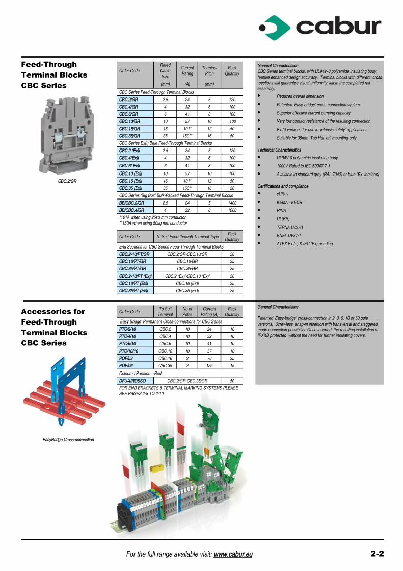
General Characteristics
CBC Series terminal blocks, with UL94V-0 polyamide insulating body,
feature enhanced design accuracy. Terminal blocks with different cross
-sections still guarantee visual uniformity within the completed rail
assembly.
Reduced overall dimension
Patented ‘Easy-bridge’ cross-connection system
Superior effective current carrying capacity
Very low contact resistance of the resulting connection
Ex (i) versions for use in ‘intrinsic safety’ applications
Suitable for 35mm ‘Top Hat’ rail mounting only
Technical Characteristics
UL94V-0 polyamide insulating body
1000V Rated to IEC 60947-7-1
Available in standard grey (RAL 7042) or blue (Ex versions)
Certifications and compliance
cURus
KEMA - KEUR
RINA
UL(BR)
TERNA LV27/1
ENEL DV27/1
ATEX Ex (e) & IEC (Ex) pending
Feed-Through
Terminal Blocks
CBC Series
CBC.2/GR
Order Code
Rated
Cable
Size
Current
Rating
Terminal
Pitch
Pack
Quantity
(mm) (A) (mm)
CBC Series Feed-Through Terminal Blocks
CBC.2/GR 2.5 24 5 120
CBC.4/GR 4 32 6 100
CBC.6/GR 6 41 8 100
CBC.10/GR 10 57 10 100
CBC.16/GR 16 101* 12 50
CBC.35/GR 35 150** 16 50
CBC Series Ex(i) Blue Feed-Through Terminal Blocks
CBC.2 (Ex)i 2.5 24 5 120
CBC.4(Ex)i 4 32 6 100
CBC.6( Ex)i 6 41 8 100
CBC.10 (Ex)i 10 57 10 100
CBC.16 (Ex)i 16 101* 12 50
CBC.35 (Ex)i 35 150** 16 50
CBC Series ‘Big Box’ Bulk-Packed Feed-Through Terminal Blocks
BB/CBC.2/GR 2.5 24 5 1400
BB/CBC.4/GR 4 32 6 1000
*101A when using 25sq mm conductor
**150A when using 50sq mm conductor
Order Code To Suit
Terminal
No of
Poles
Current
Rating (A)
Pack
Quantity
‘Easy Bridge’ Permanent Cross-connections for CBC Series
PTC/2/10 CBC.2 10 24 10
PTC/4/10 CBC.4 10 32 10
PTC/6/10 CBC.6 10 41 10
PTC/10/10 CBC.10 10 57 10
POF/53 CBC.16 2 76 25
POF/06 CBC.35 2 125 15
Order Code To Suit Feed-through Terminal Type Pack
Quantity
End Sections for CBC Series Feed-Through Terminal Blocks
CBC.2-10/PT/GR CBC.2/GR-CBC.10/GR 50
CBC.16/PT/GR CBC.16/GR 25
CBC.35/PT/GR CBC.35/GR 25
CBC.2-10/PT (Ex)i CBC.2 (Ex)i-CBC.10 (Ex)i 50
CBC.16/PT (Ex)i CBC.16 (Ex)i 25
CBC.35/PT (Ex)i CBC.35 (Ex)i 25
Coloured Partition—Red
DFU/4/ROSSO CBC.2/GR-CBC.35/GR 50
FOR END BRACKETS & TERMINAL MARKING SYSTEMS PLEASE
SEE PAGES 2-8 TO 2-10
Accessories for
Feed-Through
Terminal Blocks
CBC Series
EasyBridge Cross-connection
General Characteristics
Patented ‘Easy-bridge’ cross-connection in 2, 3, 5, 10 or 50 pole
versions. Screwless, snap-in insertion with transversal and staggered
mode connection possibility. Once inserted, the resulting installation is
IPXXB protected without the need for further insulating covers.
For the full range available visit: www.cabur.eu 2-2

Special Version
Terminal Blocks
Order Code Description
Rated
Cable
Size
Pack
Qty
(mm)
Two & Three Level Terminal Blocks
DBC.2/GR 2 Level Feed-Through - Grey -
35mm ‘Top Hat’ mounting only 2.5 120
DAS.4 2 Level Feed-Through 4 120
TLD.2 3 Level Feed-Through 2.5 125
Fused Terminal Blocks
SFR.4 Link Blade 5x20mm 6.3A Max 4 70
Order Code To Suit Terminal Type Pack
Qty
End Sections for Special Version Terminal Blocks
DBC/PT/GR Grey for DBC.2/GR 25
DAS/PT DAS.4 25
TLD/PT/GR Grey for TLD.2/GR 25
SFR/PT SFR.4 25
General Characteristics - Two & Three-Level Terminal Blocks
Two & three level terminal blocks, with Cabur polyamide insulating body
Feed-through on 2 or 3 levels
Suitable for 35mm ‘Top Hat’ rail mounting
Version for proximity sensors
Technical Characteristics
UL94V-0 polyamide insulating body
Available in standard beige RAL 1001 (or grey RAL 7042
where indicated)
Certifications and compliance
cURus / KEMA-KEUR / RINA/ Lloyds Register
General Characteristics - Fused Terminal Blocks
Fuseholder terminals, with Cabur polyamide insulating body
Available for 5x20mm or 6x32mm fuses
Suitable for both 35mm ‘Top Hat’ or 32mm ‘G’ rail mounting
Technical Characteristics
UL94V-0 polyamide insulating body
Available in standard beige RAL 1001 (or grey RAL 7042
where indicated)
Certifications and compliance
cURus / KEMA-KEUR / RINA / Lloyds Register
DBC.2/GR
SFR.4/GR
Order Code Description
Rated
Cable
Size
Pack
Qty
(mm)
Earth Terminal Blocks
TEO.2 Earth for 35mm ‘Top Hat’ Rail 2.5 75
TEO.4 Earth for 35mm ‘Top Hat’ Rail 4 50
TE.6/O Earth for 35mm ‘Top Hat’ Rail 6 45
TE.10/O Earth for 35mm ‘Top Hat’ Rail 10 35
TE.16/O Earth for 35mm ‘Top Hat’ Rail 16 30
TE.50/O Earth for 35mm ‘Top Hat’ Rail 50 15
Order Code To Suit Earth Terminal Type Pack
Qty
End Sections for Earth Terminal Blocks
TEO.2/PT TEO.2 50
TEO.4/PT TEO.4 50
Earth Terminal Blocks
TEO.2
TE.16/O
General Characteristics
Earth terminal blocks, with Cabur polyamide green/yellow insulating
body
Versions suitable for either 35mm ‘Top Hat’ or 32mm ‘G’ rail
mounting
Technical Characteristics
UL94V-0 polyamide insulating body
Operating temperature range: -40 ÷ +80 °C
Certifications and compliance
cURus
KEMA-KEUR
RINA
ENEL LV27/7
CESI 02ATEX 061 U EEx e certificate
Order Code Rated Cable and Lug
Size
Current
Rating Pack Qty
(mm) (A)
GPM Series Insulated Studded Bar Power Feed Through Terminal Blocks
GPM.95/BB 95/M8 232 10
GPM.150/BB 150/M10 309 6
GPM.240/BB 240/M12 415 4
GPM.150/BB
High Current
Terminal Blocks
General Characteristics
Power terminal blocks, with Cabur polyamide insulating body
Possibility to perform cross connections
Suitable for both 35mm ‘Top Hat’ and 32mm ‘G’ rail mounting
Technical Characteristics
UL94V-0 polyamide insulating body
Operating temperature range: -40 ÷ +80 °C
Certifications and compliance
cULus pending / KEMA-KEUR / RINA
Order Code No. of Poles Terminal Size Colour
Multi-pole Neutral / Earth Terminals
QBLOK.7/BLU 7 10mm Blue
QBLOK.7/TE 7 10mm Green
QBLOK.12/BLU 12 10mm Blue
QBLOK.12/TE 12 10mm Green
Distribution Terminals
QBLOK.7/BLU
General Characteristics - Multi-pole Neutral/Earth Terminals
Multipole Neutral or Earth terminals with 35mm Top Hat
Mounting
PA6 Insulating body
2-3 For the full range available visit: www.cabur.eu
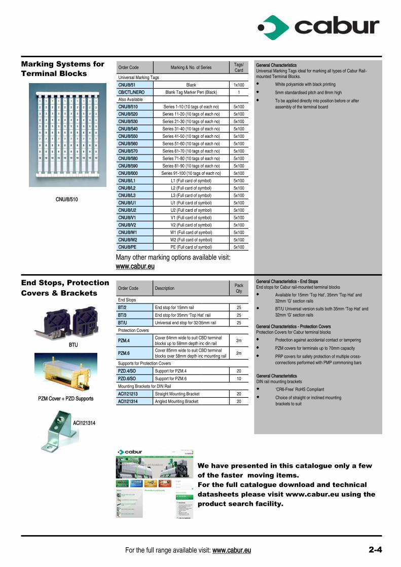
Marking Systems for Order Code Marking & No. of Series
Tags/
Card
Universal Marking Tags
CNU/8/51 Blank 1x100
CB/CTL/NERO Blank Tag Marker Pen (Black) 1
Also Available
CNU/8/510 Series 1-10 (10 tags of each no) 5x100
CNU/8/520 Series 11-20 (10 tags of each no) 5x100
CNU/8/530 Series 21-30 (10 tags of each no) 5x100
CNU/8/540 Series 31-40 (10 tags of each no) 5x100
CNU/8/550 Series 41-50 (10 tags of each no) 5x100
CNU/8/560 Series 51-60 (10 tags of each no) 5x100
CNU/8/570 Series 61-70 (10 tags of each no) 5x100
CNU/8/580 Series 71-80 (10 tags of each no) 5x100
CNU/8/590 Series 81-90 (10 tags of each no) 5x100
CNU/8/600 Series 91-100 (10 tags of each no) 5x100
CNU/8/L1 L1 (Full card of symbol) 5x100
CNU/8/L2 L2 (Full card of symbol) 5x100
CNU/8/L3 L3 (Full card of symbol) 5x100
CNU/8/U1 U1 (Full card of symbol) 5x100
CNU/8/U2 U2 (Full card of symbol) 5x100
CNU/8/V1 V1 (Full card of symbol) 5x100
CNU/8/V2 V2 (Full card of symbol) 5x100
CNU/8/W1 W1 (Full card of symbol) 5x100
CNU/8/W2 W2 (Full card of symbol) 5x100
CNU/8/PE PE (Full card of symbol) 5x100
General Characteristics
Universal Marking Tags ideal for marking all types of Cabur Rail-
mounted Terminal Blocks.
White polyamide with black printing
5mm standardised pitch and 8mm high
To be applied directly into position before or after
assembly of the terminal board
Terminal Blocks
CNU/8/510
Order Code Description Pack
Qty
End Stops
BT/2 End stop for 15mm rail 25
BT/3 End stop for 35mm ‘Top Hat’ rail 25
BT/U Universal end stop for 32/35mm rail 25
Protection Covers
PZM.4 Cover 64mm wide to suit CBD terminal
blocks up to 58mm depth inc din rail 2m
PZM.6 Cover 85mm wide to suit CBD terminal
blocks over 58mm depth inc mounting rail 2m
Supports for Protection Covers
PZD.4/SO Support for PZM.4 20
PZD.6/SO Support for PZM.6 10
Mounting Brackets for DIN Rail
ACI121213 Straight Mounting Bracket 20
ACI121314 Angled Mounting Bracket 20
End Stops, Protection
Covers & Brackets
BTU
PZM Cover + PZD Supports
ACI121314
General Characteristics - End Stops
End stops for Cabur rail-mounted terminal blocks
Available for 15mm ‘Top Hat’, 35mm ‘Top Hat’ and
32mm ‘G’ section rails
BT/U Universal version suits both 35mm ‘Top Hat’ and
32mm ‘G’ section rails
General Characteristics - Protection Covers
Protection Covers for Cabur terminal blocks
Protection against accidental contact or tampering
PZM covers for terminals up to 70mm capacity
PRP covers for safety protection of multiple cross-
connections performed with PMP commoning bars
General Characteristics
DIN rail mounting brackets
‘CR6-Free’ RoHS Compliant
Choice of straight or inclined mounting
brackets to suit
Many other marking options available visit:
www.cabur.eu
For the full range available visit: www.cabur.eu 2-4
We have presented in this catalogue only a few
of the faster moving items.
For the full catalogue download and technical
datasheets please visit www.cabur.eu using the
product search facility.

Order Code Dimensions Pack Qty
Base Height
(mm) (mm) (metres)
CZE20*
15
17 120
CZE22* 30 96
CZE25* 40 72
CZE16
25
30 80
CZE13 40 60
CZE7 60 40
CZE14 80 32
CZE34 100 24
CZE23
40
30 48
CZE8 40 40
CZE5 60 36
CZE15 80 24
CZE35 100 16
CZE24
60
30 32
CZE4 40 24
CZE9 60 24
CZE11 80 24
CZE18 100 16
CZE26
80
40 24
CZE6 60 24
CZE12 80 24
CZE36 100 16
CZE27
100
40 16
CZE17 60 20
CZE19 80 16
CZE37 100 16
CZE43 150 8
CZE28
120
40 16
CZE10 60 16
CZE32 80 16
CZE38 100 8
CZE30
150
60 12
CZE33 80 12
CZE39 100 8
CZE31 60 8
200 CZE48 80 8
CZE40 100 8
3-1
Grey Standard Open
Slot Trunking
General Characteristics
Wiring ducts with large fingers and larger slots for easy insertion of
larger wires and cables. Lead free.
Smooth wire entry allows for quick insertion of wires
Built-in wire retainer - double restricted slots on some sizes
Smooth fingers will not injure the installer or damage cables
Staggered mounting hole pattern for use in cabinets which
are designed to these standards.
Double scoreline allows easy removal of wall section or
individual fingers by hand without the use of tools
Non-slip cover with exclusive cover design with maximum
grip
RoHS Certified - Lead Free
Manufactured in 2m lengths
Technical Characteristics
Wire ducts with 8mm slots (4mm for CZE20, 22 & 25)
Self extinguishing rigid PVC Class 1 (UL94-VO)
Colour: Grey - RAL7030
Certifications and compliance
A Norme EN50085-2-3
CSA
UR
RINA
CE marked
CZE Standard Slot Trunking
*Note: Trunking with 4mm slots
Order Code To Suit Trunking
Base Width
(mm)
CZGCOP25 25
CZGCOP40 40
CZGCOP60 60
CZGCOP80 80
CZGCOP100 100
CZGCOP150 150
Spare Trunking Lid
Trunking Lid
Covers for Standard and Narrow Slot Trunking.
Supplied in 2m lengths
Colour: Grey - RAL7030
RoHS Certified - Lead Free

3-2
Grey Narrow Open
Slot Trunking
CZE..4 Narrow Slot Trunking
General Characteristics
Designed for terminal block and Din component applications with higher
number of entries into the duct. Lead free.
Smooth wire entry allows for quick insertion of wires
Built-in wire retainer - double restricted slots on some sizes
Smooth fingers will not injure the installer or damage cables
Staggered mounting hole pattern for use in cabinets which
are designed to these standards.
Double scoreline allows easy removal of wall section or
individual fingers by hand without the use of tools
Non-slip cover with exclusive cover design with maximum
grip
RoHS Certified - Lead Free
Manufactured in 2m lengths
Technical Characteristics
Wire ducts with 4mm slots
Self extinguishing rigid PVC Class 1 (UL94-VO)
Colour: Grey - RAL7030
Certifications and compliance
A Norme EN50085-2-3
CSA
UR
RINA
CE marked
Order Code Dimensions Pack Qty
Base Height
(mm) (mm) (metres)
CZE164
25
30 80
CZE134 40 60
CZE74 60 40
CZE144 80 32
CZE344 100 24
CZE84
40
40 40
CZE54 60 36
CZE154 80 24
CZE354 100 16
CZE44
60
40 24
CZE94 60 24
CZE114 80 24
CZE184 100 16
CZE264
80
40 24
CZE64 60 24
CZE124 80 24
CZE364 100 16
CZE174
100
60 20
CZE194 80 16
CZE374 100 16
CZE104 60 16 120
CZE324 80 16
Order Code To Suit Trunking
Base Width
(mm)
CZGCOP25 25
CZGCOP40 40
CZGCOP60 60
CZGCOP80 80
CZGCOP100 100
CZGCOP150 150
Spare Trunking Lid
Trunking Lid
Covers for Standard and Narrow Slot Trunking.
Supplied in 2m lengths
Colour: Grey - RAL7030
RoHS Certified - Lead Free
CZED110K60
‘EDGE’ Trunking General Characteristics
EDGE angular slotted trunking with 4mm slots for electrical panels .
The Edge wire duct is designed to be used on the very corner of the
enclosure where the space is normally not utilized. This system allows
wires and cables to be routed professionally to the lateral panels.
One single size, 110 X 110 mm with 60 mm opening
Colour: Grey - RAL7030
RoHS Certified - Lead Free
Manufactured in 2m lengths
Certifications and compliance
A Norme EN50085-2-3
CSA
UR
CE
60
60
110
110
16
Dimensions (mm)
Order Code Dimensions
(mm)
Pack Qty
(metres)
CZED110K60 110 x 110 x 60 8

3-3
Halogen Free Open
Slot Trunking
EHF Halogen-free Open Slot Trunking
Order Code Dimensions Pack Qty
Base Height
(mm) (mm) (metres)
EHF2525
25
25 84
EHF2537 37.5 64
EHF2550 50 52
EHF2575 75 32
EHF3737
37.5
37.5 48
EHF3750 50 32
EHF3775 75 32
EHF5050 50
50 24
EHF5075 75 24
EHF7550 75
50 24
EHF7575 75 16
EHF10050 50 16 100
EHF10075 75 16
EHF12575 125 75 12
General Characteristics
Alofree wiring ducts are safe products: free from halogen additives, they
do not release toxic or corrosive gases and do not propagate flames as
the surface carbonisation prevents the material from catching fire, even
when in direct contact with the flames. They develop good resistance to
chemical and marine substances and have high insulating power. All
the corners in the open type trunking are rounded to prevent injury and
to avoid cuts in the cable insulation.
They are recommended for use in:
Public buildings with a high density of people such as:
Hotels, Cinemas, Theatres, Supermarkets, Offices, Banks
Rail Vehicles: Underground Trains, High Speed Trains etc
Hostile environments such as: Nuclear reactors, Petrochemi-
cal plants, Offshore Oil Platforms
Military applications such as: Aircraft, Armoured vehicles,
Submarines, Ships
Technical Characteristics
UL94-VO
NFF2 (old VDE 0472 prt 815)
Temperature class 113 (-25degC to +105degC)
Available in standard grey colour RAL7035
Manufactured in 2m lengths
Approvals & Certification
CE
General Characteristics
Self-extinguishing rigid PVC Class 1 (UL94-V0)
Available in grey colour RAL7030
Manufactured in 2m lengths
Approvals & Certification
A Norme EN50085-2-3
CSA
CE
DIN Size Open Slot
Trunking
ED DIN Size Open Slot Trunking
Order Code Dimensions Pack Qty
Base Height
(mm) (mm) (metres)
ED2525
25
25 84
ED2537 37.5 64
ED2550 50 52
ED2575 75 32
ED3737
37.5
37.5 48
ED3750 50 32
ED3775 75 32
ED5050 50
50 24
ED5075 75 24
ED7550 75
50 24
ED7575 75 16
ED10050 50 16 100
ED10075 75 16
ED12575 125 75 12
3-4
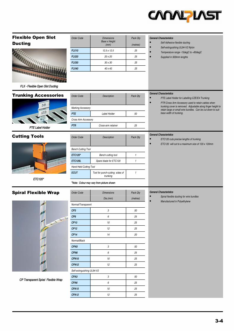
Flexible Open Slot
Ducting
General Characteristics
Self Adhesive flexible ducting
Self-extinguishing UL94-V2 Nylon
Temperature range -15degC to +80degC
Supplied in 500mm lengths
Order Code Dimensions
Base x Height
(mm)
Pack Qty
(metres)
FLX10 12.5 x 12.5 25
FLX20 20 x 20 25
FLX30 30 x 30 25
FLX40 40 x 40 25
FLX - Flexible Open Slot Ducting
Trunking Accessories
PTE Label Holder
Order Code Description Pack Qty
Marking Accessory
PTE Label Holder 50
Cross Arm Accessory
PTR Cross-arm retainer 25
Order Code Dimensions Pack Qty
Dia (mm) (metres)
Normal/Transparent
CP3 3 50
CP6 6 25
CP10 10 25
CP12 12 25
CP14 14 20
Normal/Black
CPN3 3 50
CPN6 6 25
CPN10 10 25
CPN12 12 25
Self-extinguishing UL94-V2
CPA3 3 50
CPA6 6 25
CPA10 10 25
CPA12 12 25
Spiral Flexible Wrap
CP Transparent Spiral Flexible Wrap
Cutting Tools Order Code Description Pack Qty
Bench Cutting Tool
ETC120* Bench cutting tool 1
ETC120L Spare blade for ETC120 1
Hand Held Cutting Tool
ECUT Tool for punch-cutting sides of
trunking
1
ETC120* *Note: Colour may vary from picture shown
General Characteristics
ETC120 cuts precise lengths of trunking
ETC120 will cut to a maximum size of 120 x 120mm
General Characteristics
PTE Label Holder for Labelling CZE/E4 Trunking
PTR Cross Arm Accessory used to retain cables when
trunking cover is removed. Adjustable along finger height to
retain large or small wire bundles. Can be cut down to suit
base width of trunking.
General Characteristics
Spiral flexible ducting for wire bundles
Manufactured in Polyethylene

4-1
Open-type Panel
Transformers
Order Code Primary Secondary Dimensions
Voltage
(VAC)
Voltage
(VAC)
H x W x D
(mm)
30VA Rated
TM030.240.024 220/240 24 75 x 75 x 65
50VA Rated
TM050.240.024 220/240 24
82 x 85 x 75
TM050.240.110 220/240 110
TM050.415.024 380/415 24
TM050.415.110 380/415 110
TM050.415.240 380/415 240
100VA Rated
TM110.240.024 220/240 24
82 x 85 x 95
TM110.240.110 220/240 110
TM110.415.024 380/415 24
TM110.415.110 380/415 110
TM110.415.240 380/415 240
150VA Rated
TM115.240.024 220/240 24
105 x 100 x 95
TM115.240.110 220/240 110
TM115.415.024 380/415 24
TM115.415.110 380/415 110
TM115.415.240 380/415 240
200VA Rated
TM120.240.024 220/240 24
105 x 100 x 105
TM120.240.110 220/240 110
TM120.415.024 380/415 24
TM120.415.110 380/415 110
TM120.415.240 380/415 240
300VA Rated
TM130.240.024 220/240 24
120 x 122 x 95
TM130.240.110 220/240 110
TM130.415.024 380/415 24
TM130.415.110 380/415 110
TM130.415.240 380/415 240
400VA Rated
TM140.240.024 220/240 24
120 x 122 x 115
TM140.240.110 220/240 110
TM140.415.024 380/415 24
TM140.415.110 380/415 110
TM140.415.240 380/415 240
500VA Rated
TM150.240.024 220/240 24
120 x 122 x 135
TM150.240.110 220/240 110
TM150.415.024 380/415 24
TM150.415.110 380/415 110
TM150.415.240 380/415 240
750VA Rated
TM175.240.024 220/240 24
150 x 155 x 125 TM175.240.110 220/240 110
TM175.415.110 380/415 110
TM175.415.240 380/415 240
General Characteristics
Open-style single phase separation-type power transformers for
electrical panels
Simple wiring via large terminal block
Double-wound centre-tapped construction
Low loss laminations
Earth connection on frame
Available in sizes 30VA upto 2kVA
Technical Characteristics
Thermal insulation Class B
Insulation Voltage Primary/Secondary 3.5kV
Max Ambient Temp 40oC
Frequency 50/60Hz
Electrical protection Class I
Weights
30VA 1kg
50VA 1.5kg
100VA 2.3kg
150VA 2.7kg
200VA 3.2kg
300VA 4.2kg
400VA 5.8kg
500VA 7.8kg
750VA 9kg
Certifications and compliance
In accordance with EN61558-2-1
In accordance with CEI14-8
In accordance with IEC726
Wiring Diagram for TM Range
All standard transformers are voltage input 0-380-415V or
voltage input 0-220-240V
TRANS- FORMER TER-
MINAL BLOCK
W- - - - - - SCREEN TO BE CONNECTED TO EARTH
NOTES
Connect for:
a) 0-220-240V input, EITHER 220V OR 240V only
b) 0-380-415V input, EITHER 380V OR 415V only
Output of transformer is centre tapped
For 24V output connect between 0 and 24, for 110V output
connect between 0 and 110, for 240V output connect
between 0 and 240V
Earth screen to be connected to screw and nut on side of
transformer and to W terminal on transformer terminal block.
A cable from this connection to be connected to earth
TM Series
Input Supply Output Supply
0 220 240 W
0 24
0 380 415 0 110
0 240
4-2
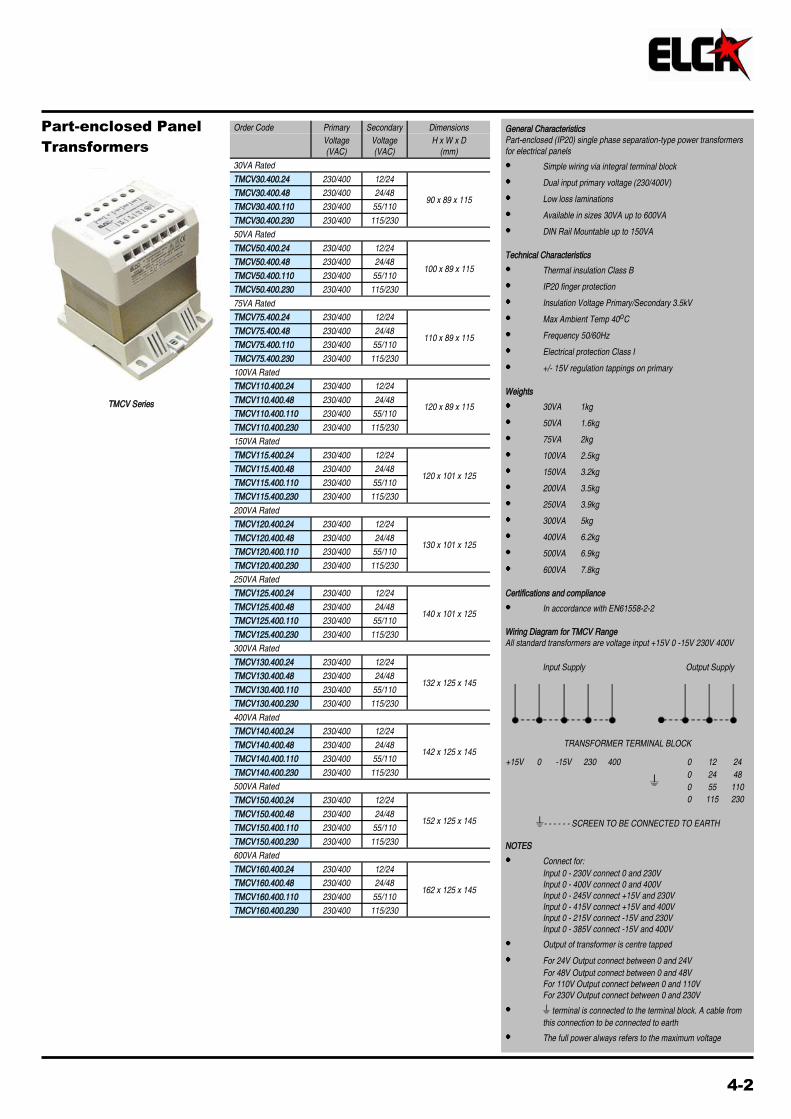
Part-enclosed Panel
Transformers
TMCV Series
Order Code Primary Secondary Dimensions
Voltage
(VAC)
Voltage
(VAC)
H x W x D
(mm)
30VA Rated
TMCV30.400.24 230/400 12/24
90 x 89 x 115 TMCV30.400.48 230/400 24/48
TMCV30.400.110 230/400 55/110
TMCV30.400.230 230/400 115/230
50VA Rated
TMCV50.400.24 230/400 12/24
100 x 89 x 115 TMCV50.400.48 230/400 24/48
TMCV50.400.110 230/400 55/110
TMCV50.400.230 230/400 115/230
75VA Rated
TMCV75.400.24 230/400 12/24
110 x 89 x 115 TMCV75.400.48 230/400 24/48
TMCV75.400.110 230/400 55/110
TMCV75.400.230 230/400 115/230
100VA Rated
TMCV110.400.24 230/400 12/24
120 x 89 x 115 TMCV110.400.48 230/400 24/48
TMCV110.400.110 230/400 55/110
TMCV110.400.230 230/400 115/230
150VA Rated
TMCV115.400.24 230/400 12/24
120 x 101 x 125 TMCV115.400.48 230/400 24/48
TMCV115.400.110 230/400 55/110
TMCV115.400.230 230/400 115/230
200VA Rated
TMCV120.400.24 230/400 12/24
130 x 101 x 125 TMCV120.400.48 230/400 24/48
TMCV120.400.110 230/400 55/110
TMCV120.400.230 230/400 115/230
250VA Rated
TMCV125.400.24 230/400 12/24
140 x 101 x 125 TMCV125.400.48 230/400 24/48
TMCV125.400.110 230/400 55/110
TMCV125.400.230 230/400 115/230
300VA Rated
TMCV130.400.24 230/400 12/24
132 x 125 x 145 TMCV130.400.48 230/400 24/48
TMCV130.400.110 230/400 55/110
TMCV130.400.230 230/400 115/230
400VA Rated
TMCV140.400.24 230/400 12/24
142 x 125 x 145 TMCV140.400.48 230/400 24/48
TMCV140.400.110 230/400 55/110
TMCV140.400.230 230/400 115/230
500VA Rated
TMCV150.400.24 230/400 12/24
152 x 125 x 145 TMCV150.400.48 230/400 24/48
TMCV150.400.110 230/400 55/110
TMCV150.400.230 230/400 115/230
600VA Rated
TMCV160.400.24 230/400 12/24
162 x 125 x 145 TMCV160.400.48 230/400 24/48
TMCV160.400.110 230/400 55/110
TMCV160.400.230 230/400 115/230
General Characteristics
Part-enclosed (IP20) single phase separation-type power transformers
for electrical panels
Simple wiring via integral terminal block
Dual input primary voltage (230/400V)
Low loss laminations
Available in sizes 30VA up to 600VA
DIN Rail Mountable up to 150VA
Technical Characteristics
Thermal insulation Class B
IP20 finger protection
Insulation Voltage Primary/Secondary 3.5kV
Max Ambient Temp 40oC
Frequency 50/60Hz
Electrical protection Class I
+/- 15V regulation tappings on primary
Weights
30VA 1kg
50VA 1.6kg
75VA 2kg
100VA 2.5kg
150VA 3.2kg
200VA 3.5kg
250VA 3.9kg
300VA 5kg
400VA 6.2kg
500VA 6.9kg
600VA 7.8kg
Certifications and compliance
In accordance with EN61558-2-2
Wiring Diagram for TMCV Range
All standard transformers are voltage input +15V 0 -15V 230V 400V
TRANSFORMER TERMINAL BLOCK
W- - - - - - SCREEN TO BE CONNECTED TO EARTH
NOTES
Connect for:
Input 0 - 230V connect 0 and 230V
Input 0 - 400V connect 0 and 400V
Input 0 - 245V connect +15V and 230V
Input 0 - 415V connect +15V and 400V
Input 0 - 215V connect -15V and 230V
Input 0 - 385V connect -15V and 400V
Output of transformer is centre tapped
For 24V Output connect between 0 and 24V
For 48V Output connect between 0 and 48V
For 110V Output connect between 0 and 110V
For 230V Output connect between 0 and 230V
W terminal is connected to the terminal block. A cable from
this connection to be connected to earth
The full power always refers to the maximum voltage
Input Supply Output Supply
+15V 0 -15V 230 400 0 12 24
W 0 24 48
0 55 110
0 115 230

The products illustrated in this publication are subject to revision or improvement at any time. Catalogue descriptions, technical and operational data as well as other details herein specified do not have any contractual value and must be considered only as an indication. The products must be installed and used only by qualified personnel in accordance with the relevant regulations in force for electrical installations and systems in order to avoid damage or safety hazards. E.&E.O.
Notes

LOVATO ELECTRIC LTD
ENERGY AND AUTOMATION
LOVATO HOUSE
PROVIDENCE DRIVE
STOURBRIDGE
WEST MIDLANDS DY9 8HQ
TEL 08458 110023 or 01384 899700
FAX 08458 110024 or 01384 891654
Email [email protected]
www.lovato.co.uk
CONTROL
AND
SIGNALLING
CIRCUIT
PROTECTION
ISOLATION
AUTOMATION
AND
CONTROL
ENERGY
MANAGEMENT
MOTOR
CONTROL
PROTECTION