15 may 2011 version 1 - aloha cabled...
TRANSCRIPT

1
Cruise Plan for R/V Kilo Moana KM1116: ALOHA Cabled Observatory and Ka‘ena Ridge
20 May – 7 June 2011
15 May 2011 Version 1.5
Bruce Howe, Chief Scientist
Department of Ocean and Resources Engineering School of Ocean and Earth Science and Technology
University of Hawaii Department Office: 2540 Dole Street, Holmes Hall 402
Office: 1680 East-West Road, POST 105G Honolulu, HI 96822
Tel: 808-956-0466 Mobile: 808-469-0553 [email protected]

2
3
Cruise Plan for R/V Kilo Moana KM1116: ALOHA Cabled Observatory and Ka‘ena Ridge
20 May – 7 June 2011
15 May 2011 Version 1.5
Bruce Howe, Chief Scientist
Department of Ocean and Resources Engineering School of Ocean and Earth Science and Technology
University of Hawaii Department Office: 2540 Dole Street, Holmes Hall 402
Office: 1680 East-West Road, POST 105G Honolulu, HI 96822
Tel: 808-956-0466 Mobile: 808-469-0553 [email protected]
Table of Contents 1. Introduction ................................................................................................................6 2. ALOHA Cabled Observatory....................................................................................7 3. Ka‘ena Ridge.............................................................................................................13 4. Jason/Medea..............................................................................................................17 5. Navigation .................................................................................................................17 6. Deck Layout ..............................................................................................................20 7. Mobilization ..............................................................................................................21 8. Responsibilities .........................................................................................................22 9. Cruise Timeline.........................................................................................................24 Appendix A – ACO Diagrams........................................................................................25 Appendix B – ACO – Cable Termination Detail ..........................................................27 Appendix C – ACO Operations .....................................................................................30 Appendix D – TAAM Mooring ......................................................................................44 Appendix E – Ka‘ena Ridge Operations .......................................................................50 Appendix F – Bathymetry in the ALOHA area............................................................51 Appendix G – Cruise Participants and Contacts List..................................................52 Appendix H – Berthing Plan ..........................................................................................54 Appendix I – Acronyms and abbreviations ..................................................................55
4
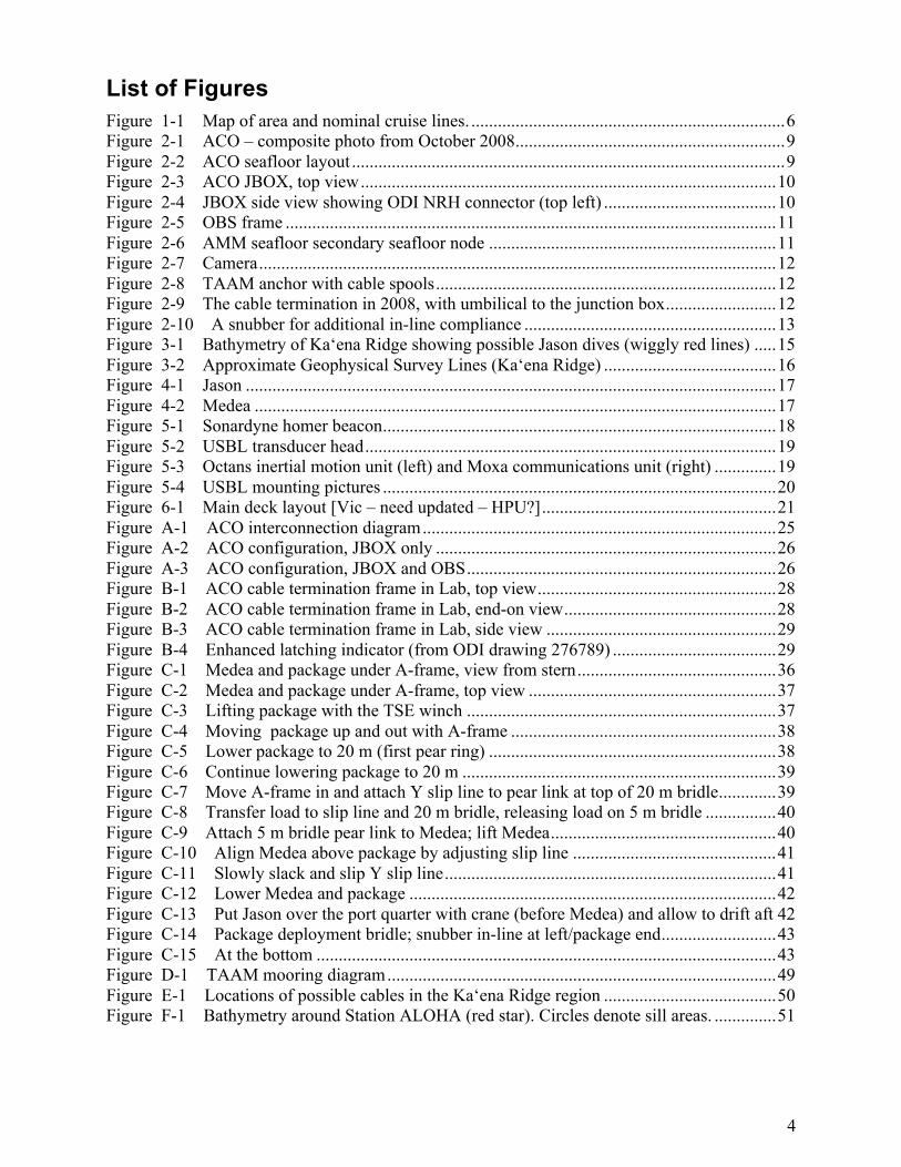
List of Figures Figure 1-1 Map of area and nominal cruise lines. .......................................................................6 Figure 2-1 ACO – composite photo from October 2008.............................................................9 Figure 2-2 ACO seafloor layout ..................................................................................................9 Figure 2-3 ACO JBOX, top view..............................................................................................10 Figure 2-4 JBOX side view showing ODI NRH connector (top left) .......................................10 Figure 2-5 OBS frame ...............................................................................................................11 Figure 2-6 AMM seafloor secondary seafloor node .................................................................11 Figure 2-7 Camera.....................................................................................................................12 Figure 2-8 TAAM anchor with cable spools.............................................................................12 Figure 2-9 The cable termination in 2008, with umbilical to the junction box.........................12 Figure 2-10 A snubber for additional in-line compliance .........................................................13 Figure 3-1 Bathymetry of Ka‘ena Ridge showing possible Jason dives (wiggly red lines) .....15 Figure 3-2 Approximate Geophysical Survey Lines (Ka‘ena Ridge) .......................................16 Figure 4-1 Jason ........................................................................................................................17 Figure 4-2 Medea ......................................................................................................................17 Figure 5-1 Sonardyne homer beacon.........................................................................................18 Figure 5-2 USBL transducer head.............................................................................................19 Figure 5-3 Octans inertial motion unit (left) and Moxa communications unit (right) ..............19 Figure 5-4 USBL mounting pictures .........................................................................................20 Figure 6-1 Main deck layout [Vic – need updated – HPU?].....................................................21 Figure A-1 ACO interconnection diagram................................................................................25 Figure A-2 ACO configuration, JBOX only .............................................................................26 Figure A-3 ACO configuration, JBOX and OBS......................................................................26 Figure B-1 ACO cable termination frame in Lab, top view......................................................28 Figure B-2 ACO cable termination frame in Lab, end-on view................................................28 Figure B-3 ACO cable termination frame in Lab, side view ....................................................29 Figure B-4 Enhanced latching indicator (from ODI drawing 276789) .....................................29 Figure C-1 Medea and package under A-frame, view from stern.............................................36 Figure C-2 Medea and package under A-frame, top view ........................................................37 Figure C-3 Lifting package with the TSE winch ......................................................................37 Figure C-4 Moving package up and out with A-frame ............................................................38 Figure C-5 Lower package to 20 m (first pear ring) .................................................................38 Figure C-6 Continue lowering package to 20 m .......................................................................39 Figure C-7 Move A-frame in and attach Y slip line to pear link at top of 20 m bridle.............39 Figure C-8 Transfer load to slip line and 20 m bridle, releasing load on 5 m bridle ................40 Figure C-9 Attach 5 m bridle pear link to Medea; lift Medea...................................................40 Figure C-10 Align Medea above package by adjusting slip line ..............................................41 Figure C-11 Slowly slack and slip Y slip line...........................................................................41 Figure C-12 Lower Medea and package ...................................................................................42 Figure C-13 Put Jason over the port quarter with crane (before Medea) and allow to drift aft 42 Figure C-14 Package deployment bridle; snubber in-line at left/package end..........................43 Figure C-15 At the bottom ........................................................................................................43 Figure D-1 TAAM mooring diagram........................................................................................49 Figure E-1 Locations of possible cables in the Ka‘ena Ridge region .......................................50 Figure F-1 Bathymetry around Station ALOHA (red star). Circles denote sill areas. ..............51

5
List of Tables Table 1-1 Coordinates of waypoints and stations ...........................................................................7 Table 3-1 Ka‘ena Ridge bathymetry line coordinates...................................................................17 Table 9-1 Cruise tasks and times (local HST time).......................................................................24 Table C-1 ACO tasks for deployment ...........................................................................................30

6
1. Introduction The purpose of this NSF-funded cruise on the R/V Kilo Moana is twofold:
• Install the ALOHA Cabled Observatory (ACO) and,
• Survey portions of the Ka‘ena Ridge and collect rock samples. The remotely operated vehicle (ROV) Jason is essential to performing the required tasks.
The cruise is 18 days long, from 20 May to 7 June 2011. The ACO work is allocated 12 days, and the Ka‘ena Ridge 4 days. The ship will depart Honolulu at 0800 and proceed directly to Ka‘ena Ridge (the underwater extension of Oahu to the northwest) to conduct a Jason engineering dive, hopefully combining this with science work. Then we proceed to Station Aloha, 100 km north, to perform the ACO work. See Figure 1-1 for a map with nominal cruise lines. Table 1-1 gives coordinates of relevant points. The balance of the Ka‘ena Ridge work will come either at the end of the cruise, or, if there are problems with the ACO (e.g., bad weather), we will come back to Ka‘ena Ridge to work.
Figure 1-1 Map of area and nominal cruise lines.

7
Latitude
deg N
minutes Longitude
deg W
minutes Incremental
distance (nmi)
UHMC, Snug Harbor 21 18.937 157 53.186 Honolulu WP1 21 16 157 54 Barbers Point WP 21 16 158 9 14 Ka‘ena Ridge Dive1 21 37.052 158 41.875 37 ACO Cable Termination
22 44.324 158 0.372 78
Station ALOHA 22 45 158 0 1
Table 1-1 Coordinates of waypoints and stations
In this Plan, we first describe the ACO system and give an overview of the installation steps. This is followed by a description of the Ka‘ena Ridge work. The Jason / Medea system is described, including the navigation system. The ship and deck configuration is described followed by a (summary) timeline of operations and then a section on responsibilities. The ACO step-by-step installation plan is given in Appendix C and D. Similarly, the details of the Ka‘ena Ridge work are given in Appendix E. Other appendices have information on the ACO cable termination, possible bathymetry mapping locations if time permits, personnel/contacts, berthing, and acronyms.
2. ALOHA Cabled Observatory The ACO is a prototypical example of a deep ocean observatory system that uses a retired cable. The ACO architecture uses highly reliable existing transoceanic cable systems to provide power and communications bandwidth. Since the cable is already in-place and is designed to operate for well beyond its commercial lifetime, costs of conversion to scientific use (as here) are substantially lower than for new systems. In the simplest terms, we want to provide power and communications ports for users to plug into on the seafloor for arbitrary instrumentation. Here, in addition we include sensors for scientific measurements of water properties, video and acoustics.
An attempt to deploy the system in October 2008 failed due to faulty ODI connector and cable assemblies. A composite photograph of the system deployed then is shown in Figure 2-1. On the right side is the cable termination with proof module above; on the left is the observatory frame. Changes have been made to the configuration, most notably separating the junction box (JBOX) from the main observatory frame (OBS), and installing an Ethernet switch in the JBOX, thereby eliminating the need for the fiber optic cable that failed. The desired layout on the seafloor is shown schematically in Figure 2-2. Photographs of the equipment during a test at Makai Pier are given in Figures 2-3 – 2-8. System block diagrams with interconnections are shown in Appendix A. Additional photographs and other system documentation can be found on the project wiki web site http://aco.wikispot.org/ and on the anonymous ftp server ftp.soest.hawaii.edu/bhowe/ACO. Also see the Jason Virtual Control Van videos from the R/V Thompson cruise in October 2008 http://4dgeo.whoi.edu/webdata/virtualvan/html/VV-tn226/index.html. The ACO cable termination as it was left in October 2008 is shown in Figure 2-9; additional photographs are in Appendix B. We will deploy and connect a “junction box” (JBOX) to the existing telecom cable termination. The JBOX converts the telecom communications protocols to standard 100 Mb/s Ethernet, and has as well a hydrophone experiment module (HEM) with two

8
hydrophones and a pressure sensor. Then the “observatory” (OBS) is connected to the JBOX. The OBS converts the dc current on the cable to 48 V and 400 V, and distributes this, the Ethernet, and timing signals to eight user ports. On the observatory are two acoustic Doppler profilers (ADPs), a temperature/conductivity instrument, and a light (not on picture yet). Additional modules will be installed and connected. First, two modules will be free-falled to the seafloor: the AMM (Aloha-Mars Mooring) seafloor secondary node and the camera. The AMM node provides four additional user ports and has two CTDO2s and a fluorometer. The camera with two lights and a hydrophone is connected to the AMM node. Lastly, the 200 m tall thermistor array/acoustic modem (TAAM) mooring system will be deployed anchor first. This mooring system has 10 thermistors spaced vertically and a fluorometer at the top; these are battery operated but communicate along the jacketed wire rope (JWR) with a Seabird inductive modem unit at the base, which is then connected to the observatory. The WHOI acoustic micro-modem at the top of the mooring has its dedicated electromechanical cable that is married to the JWR.
There has been considerable discussion regarding minimizing risks associated with the deployment of ACO components. The current plan is to deploy the JBOX and OBS beneath Medea with Jason accompanying. One risk is snap loading. If the ship heaves down faster than the package can descend slack in the connecting line will develop, which could snap depending on how the ship continues to move. Three things mitigate this risk. First, the Kilo Moana is a swath ship and therefore pitches relatively little compared to monohulls. Second, we will use ¾-inch nylon with 30 percent elongation at its 13,500 lb breaking strength (rather than Yalex with 14 percent elongation at a breaking strength of 12,500 lb). Third, we will use a “snubber” – to provide additional in-line compliance. Figure 2-10 shows this; its usual use is as a mooring compensator for small to medium boats at marinas.
During the first deployment, before Jason is attached, we will observe the performance of the JBOX beneath Medea with the video when lowered a few 10s of meters. If it appears that additional weight would improve the motion of the JBOX (akin but in an opposite sense to pre-stressing concrete), it will be recovered and weight added.
During descent with three bodies, it is possible for Jason to fail and become fouled with the other bodies (Medea and the ACO package in question). This risk is mitigated by having a small way on (1/4 kt) so that Jason is always streaming aft of Medea and the third body. If Jason’s power should fail, it will drop somewhat, but will continue to remain aft.
We will be prepared to be able to lower the ACO packages in one of three possible ways: 3 bodies (Medea, Jason, and package), 2 bodies (Medea and package), or just one body. The TAAM mooring will likely be deployed using one of the latter two scenarios, the choice depending on the preceding experience and weather.
During deployment of the JBOX and OBS, personnel from UH will be at the AT&T Makaha Cable Station to turn power on and off and to control the overall system after connection. If all is working well, command and control can then be done at UH, or anywhere in the world with an IP connection.
If all goes according to the plan laid out in detail in Appendix C and in the schedule in Table 9-1, the entire operation should take 5 days/5 dives. The schedule has explicit provision for 1 contingency dive plus ~6 days unspecified.

9
Figure 2-1 ACO – composite photo from October 2008
Figure 2-2 ACO seafloor layout

10
Figure 2-3 ACO JBOX, top view
Figure 2-4 JBOX side view showing ODI NRH connector (top left)

11
Figure 2-5 OBS frame
Figure 2-6 AMM seafloor secondary seafloor node

12
Figure 2-7 Camera
Figure 2-8 TAAM anchor with cable spools
Figure 2-9 The cable termination in 2008, with umbilical to the junction box

13
Figure 2-10 A snubber for additional in-line compliance
3. Ka‘ena Ridge Background and Rationale Bathymetric mapping, chemical analyses of limited samples and three existing K-Ar ages suggest that part of the submarine Ka‘ena Ridge that extends to the northwest of the island of O‘ahu comprises a previously undiscovered volcano, distinct from those that make up O‘ahu. Limited gravity data indicate that the structure of Ka‘ena Ridge is complex, possibly consistent with this hypothesis. The geochemical data suggest that a nearly complete sequence of compositions is present, from early, strongly alkalic lavas, similar to those from the earliest (preshield) stage of evolution of Hawaiian volcanoes, through submarine tholeiitic lavas to subaerial tholeiites. Preliminary age data suggest that the postulated Ka‘ena Volcano is 0.5-1.0 Myr younger than its nearest neighbor - Wai‘anae Volcano, despite lying to the west of Wai‘anae; i.e., in a downstream plate motion location. These results indicate an opportunity to potentially learn fundamental new things about Hawaiian magmatic activity. In particular, Ka‘ena Ridge may have one of the best-exposed sections of early magmatic evolution, and offers the potential for deconvolution of the geophysical expression of overlapping volcanic edifices. Further preliminary data suggest the first good evidence for a reversal in the age-distance shield-stage relationship along the Hawaiian chain; if confirmed, this would have important implications for plume structure, plate motions, and magma generation processes at the Hawaiian hotspot.
The Ka‘ena field program is designed to test the presence of a distinct volcanic sequence on Ka‘ena Ridge, collecting new samples and observations along selected traverses of ROV Jason, and new geophysical survey data using bathymetric mapping and gravity and magnetic data from the R/V Kilo Moana. We intend to determine the location of the submarine to subaerial transition along these traverses and collect samples, which will be analyzed post-cruise.

14
Jason Dives In four days we propose to conduct at least 4 Jason dives to be selected from the possible tracks shown on Figure 3-1. The three highest priority dive targets are one dive along the NW-trending Waialu Ridge < 2000m, and two dives comprising a transect up the SSW side of the lava shield marked by the previous Tiburon dive T325. All dives will be conducted in an up-slope direction. Additional dive tracks will be selected from among the other candidate dive targets depending on results from the first three dives and time remaining.
The first dive will constitute a test of Jason systems and will be done upon initial arrival out of Honolulu. Estimated travel time from Honolulu to first Jason dive area ~5.5 hours. The first dive will be along the ridge just east of dredge track KM-6 (see Figure 3-1). Note 200-meter contours. There are some quite steep scarps but our most important targets are the gentler, probably volcanic constructional slopes. The latter have regional slopes of ~10 degrees so there will almost certainly be local areas with slopes up to at least 30 degrees.
First Jason dive: Launch 158° 41.875’ 21° 37.052’, depth ~1950 m WP 158° 40.914’ 21° 38.872’, depth ~1680m WP 158° 39.464’ 21° 43.035’, depth ~900m Following the first Jason dive we expect to transit to Station Aloha for beginning of ACO operations. We propose running one of the geophysical survey lines (possibly Line D, see below) from south to north en route to Station ALOHA.
A possible complication to Jason dive operations is the presence of multiple telecommunication cables in the area. In Appendix E, a figure shows some possible cable locations. These locations are not known to be accurate nor necessarily complete.
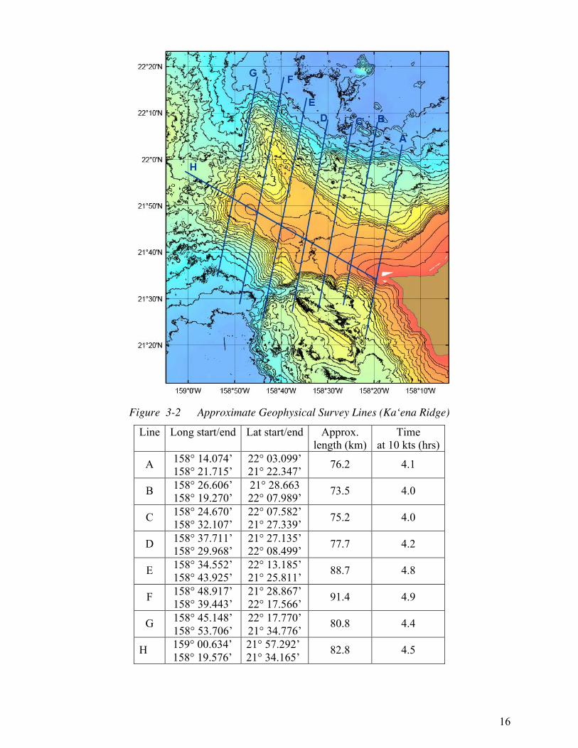
Geophysical Surveys Geophysical surveys will be run for crossings of opportunity across Ka‘ena Ridge and during turn-around times between Jason dives. Possible new geophysical survey lines are shown on figure 3. These survey lines will record gravity (shipboard gravimeter) and magnetics (towed magnetometer) run along straight lines at relatively high speed (to be determined but preferably at least 10 kts). Potential survey lines are described in Table 1, and shown on Fig. 3.3. These lines can be run in either direction, but must run without turns.

15
Figure 3-1 Bathymetry of Ka‘ena Ridge showing possible Jason dives (wiggly red lines)
16
Figure 3-2 Approximate Geophysical Survey Lines (Ka‘ena Ridge)
Line Long start/end Lat start/end Approx. length (km)
Time at 10 kts (hrs)
A 158° 14.074’ 158° 21.715’
22° 03.099’ 21° 22.347’ 76.2 4.1
B 158° 26.606’ 158° 19.270’
21° 28.663 22° 07.989’ 73.5 4.0
C 158° 24.670’ 158° 32.107’
22° 07.582’ 21° 27.339’ 75.2 4.0
D 158° 37.711’ 158° 29.968’
21° 27.135’ 22° 08.499’ 77.7 4.2
E 158° 34.552’ 158° 43.925’
22° 13.185’ 21° 25.811’ 88.7 4.8
F 158° 48.917’ 158° 39.443’
21° 28.867’ 22° 17.566’ 91.4 4.9
G 158° 45.148’ 158° 53.706’
22° 17.770’ 21° 34.776’
80.8 4.4
H 159° 00.634’ 158° 19.576’
21° 57.292’ 21° 34.165’
82.8 4.5

17
Table 3-1 Ka‘ena Ridge bathymetry line coordinates
4. Jason/Medea Jason is a two-body ROV system (Figures 4-1 and 4-2). A fiber-optic tether delivers electrical power and commands from the ship through Medea and down to Jason, which then returns data and live video imagery. Medea serves as a shock absorber, buffering Jason from the movements of the ship, while providing lighting and a bird’s eye view of the ROV during seafloor operations. On this cruise, the ship’s 0.681-inch electro-optical-mechanical cable is used as the main umbilical to Medea. Navigation is discussed in the next section.
Figure 4-1 Jason
Figure 4-2 Medea
5. Navigation Jason will navigate in three ways. First and simplest when within 200 m of the bottom, Jason uses a Doppler velocity log that gives, when integrated to obtain position, very good relative positioning within 200 m - 300 m of the seafloor. Second, some of the bottom packages will have Sonardyne “homer” beacons (35–55 kHz; Figure 4-3) and Jason can navigate relative to these, using measured roundtrip travel times.

18
Figure 5-1 Sonardyne homer beacon
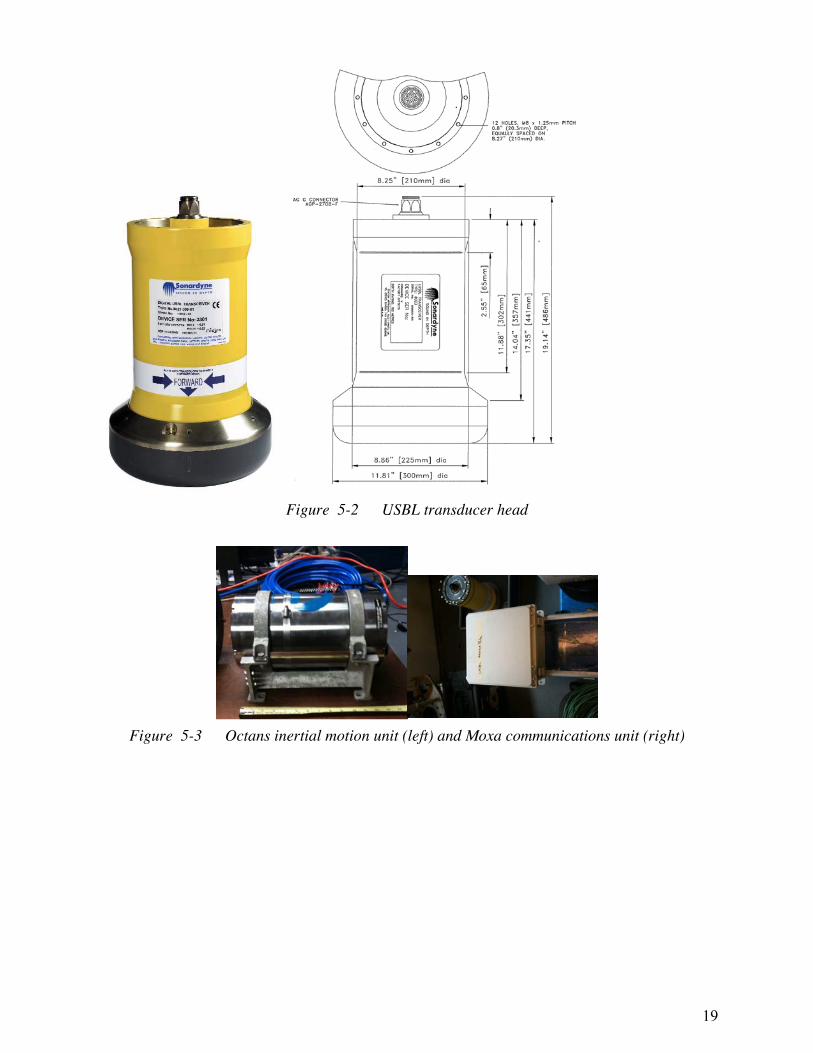
Lastly, for large area coverage, a Sonardyne ultra-short-baseline (USBL) system will be installed on the ship. A transducer pole (actually a triangular truss “radio mast”, see next section) mounted in the forward starboard transducer well will be used to lower the USBL sensor head 6-ft below the bottom of the hull. It will measure range and solid angle to beacons on Medea, Jason, and our packages. Early in the cruise a fixed beacon on the bottom will be surveyed in to determine offsets, so that absolute position can then be obtained. There is also an inertial motion unit on the transducer pole to directly measure angular motion and accelerations. The ultra-short baseline transducer is a Sonardyne Marksman LUSBL Model 8023 with a 50° wide downward looking beam. The accuracy specification is 0.27 percent 1 Drms Slant Range, i.e., 63 per cent of fixes lie within 13.5-meter radius in 5,000 meters water depth.
The USBL transducer pole will be installed forward in the starboard instrument well. Pictures taken during the fabrication process are shown below (Figure 5-4). The pole is inserted through the weather deck above the galley storeroom. A chain fall will be attached to the ceiling of the storeroom above the transducer well to raise and lower it. An inertial motion unit will be mounted directly to the top of the pole. When not being moved, a cap plate will be installed on the top of the well, surrounding the pole (when up) or covering the well when down. Electronics will be set up next to the well so only an Ethernet cable needs to run to the Jason control van.
19
Figure 5-2 USBL transducer head
Figure 5-3 Octans inertial motion unit (left) and Moxa communications unit (right)

20
Figure 5-4 USBL mounting pictures
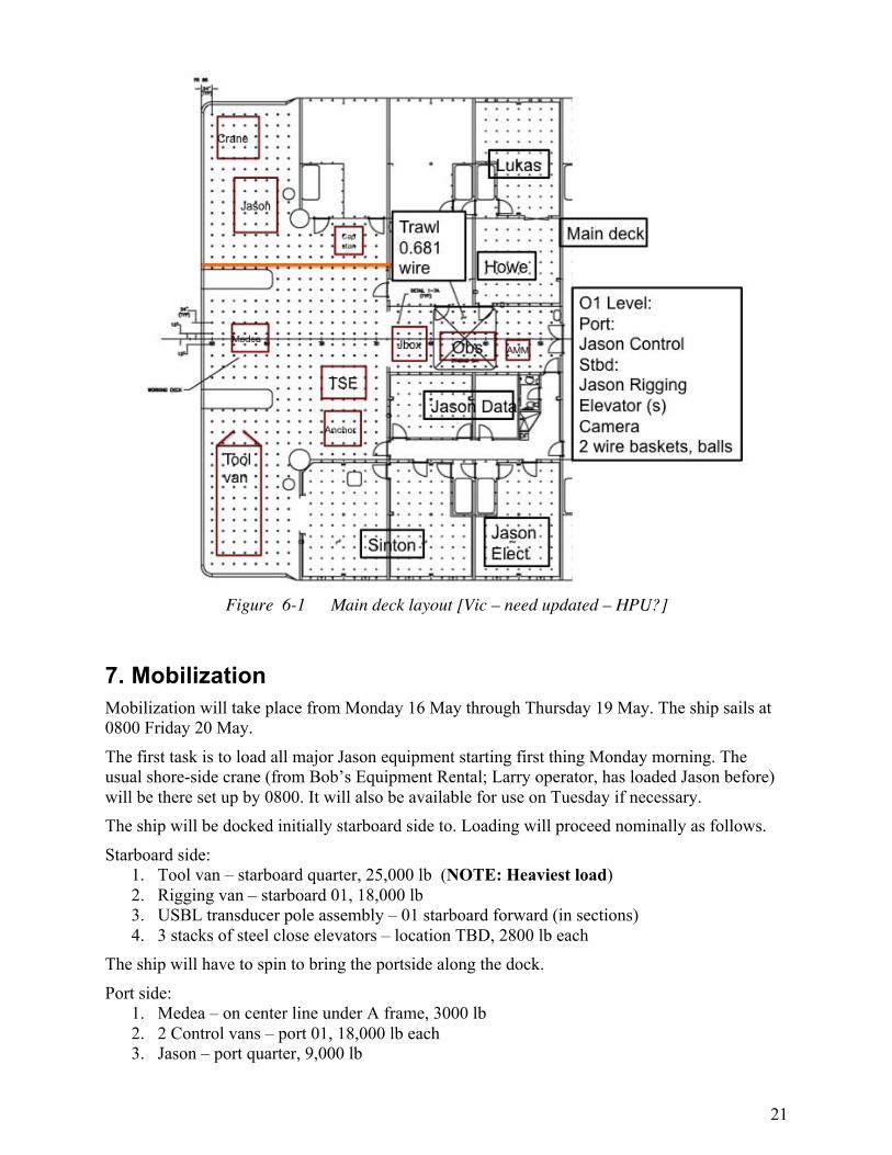
6. Deck Layout The main deck layout is shown in Figure 6-1. Jason and its crane reside on the port quarter. Medea will normally reside on the centerline under the A-frame. The TSE winch, used for the ACO package over boarding as well as for the TAAM mooring deployment, sits off-center, lined up with the starboard outboard block on the A-frame. The TAAM mooring anchor sits starboard of the TSE winch. The Jason tool van sits on the starboard quarter as close to the rails as possible (room for chain binders on corners). In the staging bay, the JBOX, OBS and AMM packages reside, connected up to electronics in Lab 2. Interior space is allocated as follows: Lab 2 is divided between Howe (ACO command and control electronics; electronics) and Lukas (sensor preparation and monitoring, mooring). Sinton will use the wet lab and the hydro lab for cataloging and storing rock samples, as well as cutting rock samples (in wet lab, with 208V from the deck socket). The Jason crew will use Lab 1 and the Chem lab for data and electronics, respectively.
On the O1 level, the Jason control vans will be sited on the port side; the rigging van will be opposite on the starboard side. Specific locations for the three elevators (used to transfer rock samples from the bottom during Ka‘ena Ridge operations) the camera tripod, and wire baskets for mooring glass balls and hardware are yet to be determined.
21
Figure 6-1 Main deck layout [Vic – need updated – HPU?]
7. Mobilization Mobilization will take place from Monday 16 May through Thursday 19 May. The ship sails at 0800 Friday 20 May.
The first task is to load all major Jason equipment starting first thing Monday morning. The usual shore-side crane (from Bob’s Equipment Rental; Larry operator, has loaded Jason before) will be there set up by 0800. It will also be available for use on Tuesday if necessary. The ship will be docked initially starboard side to. Loading will proceed nominally as follows.
Starboard side: 1. Tool van – starboard quarter, 25,000 lb (NOTE: Heaviest load) 2. Rigging van – starboard 01, 18,000 lb 3. USBL transducer pole assembly – 01 starboard forward (in sections) 4. 3 stacks of steel close elevators – location TBD, 2800 lb each
The ship will have to spin to bring the portside along the dock.
Port side: 1. Medea – on center line under A frame, 3000 lb 2. 2 Control vans – port 01, 18,000 lb each 3. Jason – port quarter, 9,000 lb

22
4. Crane – on port quarter 13,000 lb On Monday morning, two small trucks/vans will be loaded at UH with hand-carry boxes/equipment for the labs. This will be brought on board Monday afternoon using the crane and cargo nets.
The heavy ACO equipment will be brought down Tuesday morning and afternoon in two loads. This includes:
1. AMM (Figure 2-6) – forward in staging bay, 1110 lb 2. Pallet(s)/wire baskets of steel weights, etc. 3. TAAM equipment 4. OBS (Figure 2-5) – middle of staging bay, 1885 lb 5. JBOX (Figure 2-3) – aft of staging bay, 800 lb
The remaining major item to be loaded is the TAAM mooring anchor – just aft of the TSE winch, 2300 lb. This will be loaded Thursday. The ship may have to be rotated again to facilitate loading some of these items.
During the week, all equipment will be connected and tested. For ACO, a GPS antenna needs to be mounted for timing purposes (i.e., only a partial view of the sky is necessary). The large umbilical connecting electronics in the lab with the observatory packages will go through the stuffing tube next to Lab 2 door. An ACO extension cord will be run from Lab 2 to the 208V socket next to the TSE winch; the ship/OTG will supply the plug. Jason will practice using the ODI underwater mateable connectors (test setup supplied by ACO). There will be several dry runs of deployment scenarios. For the TAAM mooring, on Monday, the glass balls need to be assembled and the jacketed wire rope marked. On Tuesday, split hose to protect the communications cable from chafing needs to be made and tie wrapped on and the cable tension spooler will be set up on back deck. On Wednesday, the working wire and jacketed wire rope will be spooled on TSE winch, and the ADPs protective hats (on the OBS) will be completed. On Thursday, the anchor frame will be loaded. New batteries will be installed in the spare release. The other releases will be assembled in parallel. And, the iridium phone antenna will be installed.
8. Responsibilities The ACO science team is responsible for all the ACO packages, testing and preparing these for deployment, and providing science direction to the Jason crew during operations.
Good communications with the shore party will be essential. ACO will bring two Iridium phones. The ship will provide a third. The ship will provide Internet connectivity.
The Jason team will operate Jason and Medea, and be in charge of the deck during all deployment operations that involve their equipment. Jason will supply all bridles and lines associated with packages under Medea.
ACO will bring two working acoustic releases with dualing hardware and/or a strong back for use with the TAAM deployment. Jason will bring dualed acoustic releases as a backup.
ACO, Jason, and OTG will each bring a DS-7000 deck box or equivalent. Jason will provide two deep homer beacons. These will supplement the two UH ones. One of the latter is on a 10-ft mini-mooring next to the cable termination frame, likely dead now, and one is

23
in-hand, along with three new alkaline battery packs, one lithium battery pack, and 3 spare compression seals. Jason will service these beacons and test with their system.
ACO will supply holsters suitable for homer beacons and ODI connectors on all frames. Jason will provide at least three USBL beacons with holsters that can be deployed on ACO (and other) packages. Jason will bring 3 elevators for rock samples.
Jason will provide spare steel weights (20 lb pieces). ACO will have 8 “spelter sockets” – old cable terminations each ~80 lb with chain and shackles.
Jason will bring its sediment suction system for ACO to test/see in action for future use with the aragonite/calcite on the seawater return.
The ship will operate much of the time in dynamic positioning. Given recent past problems with the bow thruster, this needs to be inspected and tested prior to this cruise. The after steering station must be operational. This entire system must be checked out before the cruise and it must be fully operational with all backup and redundant systems operational.
The ship and OTG will provide deep and shallow water multibeam swath bathymetry, sub-bottom echosounders (3.5 kHz and 12 kHz), acoustic Doppler current profiler data/plots (using 38 kHz and 300 KHz instruments), marine gravimeter, and magnetometer and winch, two air tuggers, and pallet jack.
The TSE winch needs to be fully inspected, maintained per manufacturers requirements and tested prior to the cruise. The testing should include at a minimum a pull test when installed on deck to 6000 lb (?) at the drum.

24
9. Cruise Timeline The following table gives the major tasks and associated times. Note, Makaha Cable Station is not open 24 hours/day, but rather from 7 AM to 10 PM; this will constrain some of the activities.
There are additional tasks being called out to accomplish if we are so fortunate to have extra time: bathymetry surveying around the ALOHA site, and on and around the Ka‘ena Ridge (Appendix F and Figure 3-2, respectively).
Start End Hours Task 05/20 08:00 05/20 14:00 6 Transit Honolulu – Ka‘ena Dive 1
05/20 14:00 05/21 08:00 18 Ka‘ena Dive 1 – Engineering + Science
05/21 08:00 05/21 16:00 8 Transit Ka‘ena Dive 1/Track 1 to ACO
05/21 16:00 05/22 06:00 14 ACO Dive 1 – survey
05/22 06:00 05/22 14:00 8 Service
05/22 14:00 05/23 08:00 18 ACO Dive 2 – JBOX
05/23 08:00 05/23 14:00 6 Service
05/23 14:00 05/24 08:00 18 ACO Dive 3 – OBS; free fall: AMM,CAM
05/24 08:00 05/24 14:00 6 Service
05/24 14:00 05/25 08:00 18 ACO Dive 4 Medea – TAAM mooring
05/25 08:00 05/25 14:00 6 Service
05/25 14:00 05/26 08:00 18 ACO Dive 5 – TAAM mooring connect
05/26 08:00 05/26 14:00 6 Service
05/26 14:00 05/27 08:00 18 ACO Dive 6 – Contingency
05/27 08:00 05/27 16:00 8 Transit ACO to Ka‘ena Dive 2/Track 2
05/27 16:00 05/28 08:00 16 Ka‘ena Dive 2
05/28 08:00 05/28 14:00 6 Service and transit
05/28 14:00 05/29 08:00 18 Ka‘ena Dive 3
05/29 08:00 05/29 14:00 6 Service and transit
05/29 14:00 05/30 08:00 18 Ka‘ena Dive 4
05/30 08:00 05/30 14:00 6 Service and transit
05/30 14:00 05/31 08:00 18 Ka‘ena Dive 5 Contingency
05/31 08:00 06/06 16:00 152 Contingency, Science mapping
06/06 16:00 06/07 08:00 16 Transit to Honolulu
432 hours 18.00 days
Table 9-1 Cruise tasks and times (local HST time)

25
Appendix A – ACO Diagrams The following diagrams show components of ACO in a schematic form, naming frames, connectors and cables, pressure cases and endcaps, sensors, etc.
Figure A-1 ACO interconnection diagram

26
Figure A-2 ACO configuration, JBOX only
Figure A-3 ACO configuration, JBOX and OBS

27
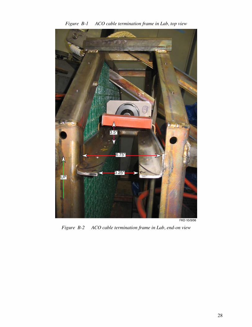
Appendix B – ACO – Cable Termination Detail One of the more crucial operations is the connection of the hybrid fiber optic/electrical ODI NRH umbilical from the JBOX to the corresponding mating connector on the sea cable termination frame on the seafloor. While this connection was made, it was after some difficulty, and it is known that this connector can jam. ROV pilots must use extreme caution in making this connection and not use excessive force.
Following are pictures of this SL280 cable termination with dimensional details (from Dave Harris, 5 June 2010; Figures B-1 – B-3).
The enhanced latching indicator (see Figure B-4) that is now on the new flying connector has a maximum diameter of 4.9 inches. Using the measurements given below in the figures, and measurements made on a near-identical HUGO frame, there is a clear 5.75-inch diameter, thus giving a 0.43-inch clearance between the frame (the 6-inch long angle is the limiting piece) and the enhanced latching indicator/flying connector.
28
Figure B-1 ACO cable termination frame in Lab, top view
Figure B-2 ACO cable termination frame in Lab, end-on view

29
Figure B-3 ACO cable termination frame in Lab, side view
Figure B-4 Enhanced latching indicator (from ODI drawing 276789)

30
Appendix C – ACO Operations The following table gives the detailed ACO tasks associated with deploying the system. Following this table are sketches showing the key aspects of deploying a generic package, Medea, and Jason.
Table C-1 ACO tasks for deployment
A. On Deck (in port or underway as time permits)
Step 1. Operator refresher on ODI connectors: • Using parking position, practice plug and unplug ODI ECs
and 12E Flying connectors with Jason. • Inspect end view of ODI NRH connectors. • After experience gained, try to mate ODI NRH on JBOX
frame. Requires bringing JBOX to Jason. Step 2. Observatory Electrical checkout:
Test JBOX, OBS, AMM, CAM, individually and connected, with ACO Surface Terminal electronics.
Step 3. Transit:
To test dive location.
B. System Test
Step 4. Calibrate USBL receive head installation at 1000 m location on Ke’ana Ridge near KM-6 site.
Step 5. Dive 1 Test Jason/Medea after maintenance. Collect rock samples along KM-6 route. End of Dive 1.
Step 6. Transit to ALOHA site. Establish ship in DP mode over previously determined Termination site.
C. ALOHA Site
Step 7. Dive 2 Reconnaissance Survey: • Carry fully charged #2 HB in transport holster mounted on
Jason. • Lower Medea/Jason. • On Bottom, locate TF, possibly using long life #1 HB
mounted in holster on float next to TF, 3 m off bottom, and/or scanning sonar.
• Remove #1 HB and replace with #2 HB. Insert #1 HB into transport holster on Jason.
• Determine azimuth orientation of TF ODI connector entry. • Map loops of shore cable around Termination Frame, range
and azimuth from termination.

31
• IF DEEMED ADVISABLE – move TF way from loops. • At TF: Remove EC from ODI NRH bulkhead connector and
store on Jason for return to ship. • Get close up, detailed images of open end of ODI NRH
bulkhead connector. • Recover Jason. End of Dive 2 • Refurbish #1 HB with fresh alkaline battery pack and test
with Jason Homer system.
D. Install and Connect Junction Box (JBOX)
Step 8. Dive 3 Lower Junction Box: • Weight 800 lbs in air. • Weight 350 lbs in water. • Be prepared to add up to 500 lbs of releasable chain for
lowering. • Install #1 HB in JBOX holster. • Install USBL beacon in JBOX holster. • Lower under Medea/Jason. • Position JBOX 4-7 meters from the TF in the direction of the
NRH bulkhead connector. • Using Medea thrusters, orient bow of JBOX toward TF
connector. Use Jason as needed. • Release JBOX lifting sling from Medea. • Document JBOX position and orientation.
Step 9. Connect Junction Box: • At JBOX: Remove #1 HB from JBOX holster and put in
Jason holster. • Remove securing straps from cable JT2 • Remove ODI NRH flying connector on cable JT2 from
parking position on JBOX. • Carry connector and drag cable to TF. • Verify from Makaha that HV power is OFF. Note that this
must be done during Makaha working hours (0700-2200 HST).
• Insert ODI NRH flying connector into TF bulkhead connector.
(THIS IS THE MOST CRITICAL
OPERATION OF THE DEPLOYMENT). • Note that excessive force (excessive would be if TF moved)
cannot be used. Connector must be lined up correctly to be inserted fully. Correct alignment is crucial.
• Advise Makaha that connection has been made. • Wait for Makaha to report connection successful. Repeat
32
mating cycle if necessary. • When good connection reported, leave locator marker for
subsequent OBS deployment. • Recover Jason. End Dive 3.
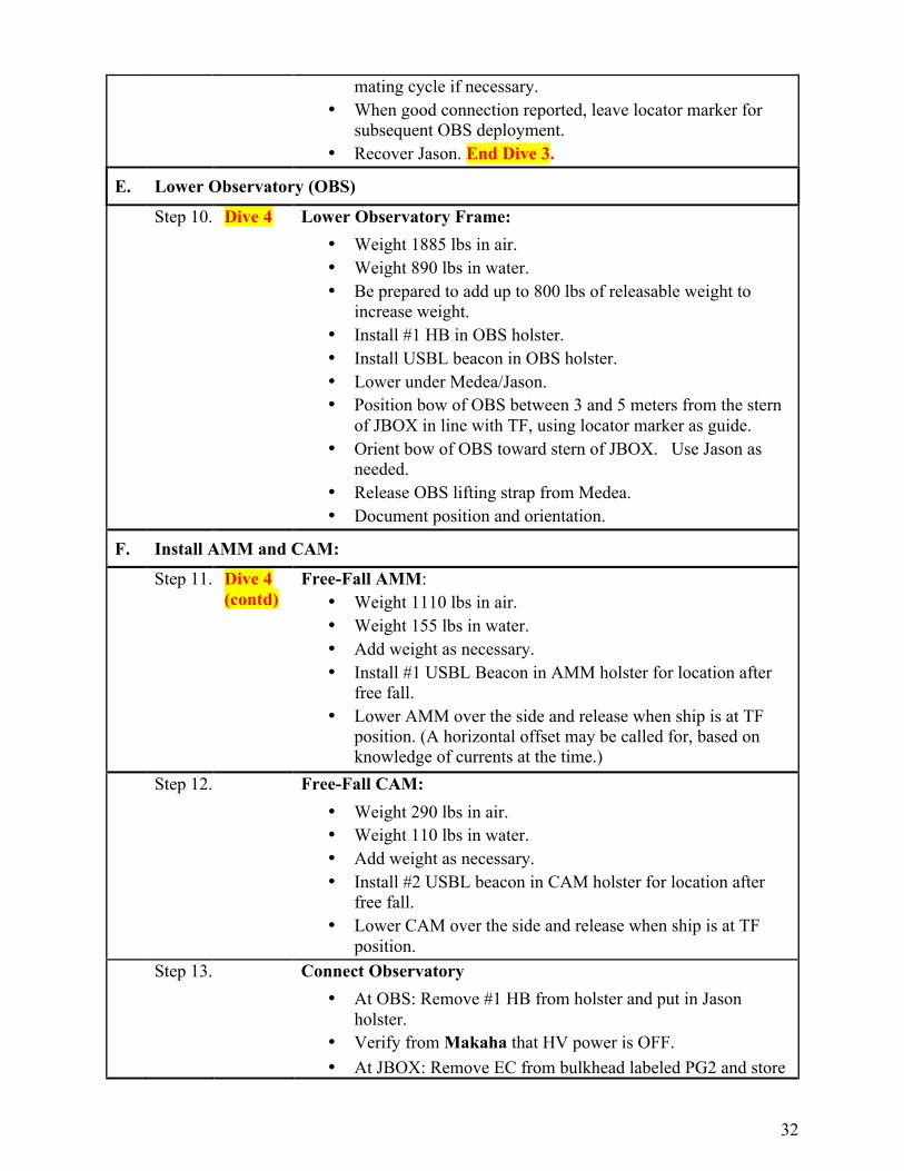
E. Lower Observatory (OBS)
Step 10. Dive 4 Lower Observatory Frame: • Weight 1885 lbs in air. • Weight 890 lbs in water. • Be prepared to add up to 800 lbs of releasable weight to
increase weight. • Install #1 HB in OBS holster. • Install USBL beacon in OBS holster. • Lower under Medea/Jason. • Position bow of OBS between 3 and 5 meters from the stern
of JBOX in line with TF, using locator marker as guide. • Orient bow of OBS toward stern of JBOX. Use Jason as
needed. • Release OBS lifting strap from Medea. • Document position and orientation.
F. Install AMM and CAM:
Step 11. Dive 4 (contd)
Free-Fall AMM: • Weight 1110 lbs in air. • Weight 155 lbs in water. • Add weight as necessary. • Install #1 USBL Beacon in AMM holster for location after
free fall. • Lower AMM over the side and release when ship is at TF
position. (A horizontal offset may be called for, based on knowledge of currents at the time.)
Step 12. Free-Fall CAM: • Weight 290 lbs in air. • Weight 110 lbs in water. • Add weight as necessary. • Install #2 USBL beacon in CAM holster for location after
free fall. • Lower CAM over the side and release when ship is at TF
position. Step 13. Connect Observatory
• At OBS: Remove #1 HB from holster and put in Jason holster.
• Verify from Makaha that HV power is OFF. • At JBOX: Remove EC from bulkhead labeled PG2 and store

33
on Jason for return to ship. • At JBOX: Remove ODI connector on cable PG2 from
bulkhead labeled JP1and insert in adjacent parking position (labeled PG2 Park).
• At OBS: Remove EC from ODI connector E5 and store on Jason for later reuse.
• At JBOX: Remove ODI flying connector on cable HE1 from JB1 bulkhead on JB.
• Carry connector and cable to OBS and connect to E5. • At OBS: Remove ODI flying connector JB2 from parking
position on OBS (labeled JB2 Park). • Carry connector and cable to JBOX and connect to JB1
bulkhead (where HE1 was). • At OBS: Install EC from Jason on parking position labeled
JB2 Park. • At OBS: Remove ODI flying connector JP2 from parking
position on OBS (labeled JP2 Park). • Carry JP2 connector and cable to JBOX and connect to JP1
bulkhead (where PG2 was). • Advise Makaha connection has been made. • Wait for Makaha to report successful connection. Adjust
cables and connectors if necessary. • At OBS: When good connection reported, remove ADP
safety covers and store on Jason for return to ship. • At OBS: Swing CTD arm up and over to forward port side of
OBS. • At OBS: Swing Camera Light arm up and over to aft port
side of OBS.
34
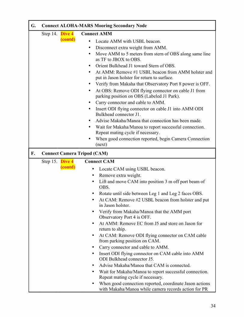
G. Connect ALOHA-MARS Mooring Secondary Node
Step 14. Dive 4 (contd)
Connect AMM • Locate AMM with USBL beacon. • Disconnect extra weight from AMM. • Move AMM to 5 meters from stern of OBS along same line
as TF to JBOX to OBS. • Orient Bulkhead J1 toward Stern of OBS. • At AMM: Remove #1 USBL beacon from AMM holster and
put in Jason holster for return to surface. • Verify from Makaha that Observatory Port 8 power is OFF. • At OBS: Remove ODI flying connector on cable J1 from
parking position on OBS (Labeled J1 Park). • Carry connector and cable to AMM. • Insert ODI flying connector on cable J1 into AMM ODI
Bulkhead connector J1. • Advise Makaha/Manoa that connection has been made. • Wait for Makaha/Manoa to report successful connection.
Repeat mating cycle if necessary. • When good connection reported, begin Camera Connection
(next)
F. Connect Camera Tripod (CAM)
Step 15. Dive 4 (contd)
Connect CAM • Locate CAM using USBL beacon. • Remove extra weight. • Lift and move CAM into position 3 m off port beam of
OBS. • Rotate until side between Leg 1 and Leg 2 faces OBS. • At CAM: Remove #2 USBL beacon from holster and put
in Jason holster. • Verify from Makaha/Manoa that the AMM port
Observatory Port 4 is OFF. • At AMM: Remove EC from J5 and store on Jason for
return to ship. • At CAM: Remove ODI flying connector on CAM cable
from parking position on CAM. • Carry connector and cable to AMM. • Insert ODI flying connector on CAM cable into AMM
ODI Bulkhead connector J5. • Advise Makaha/Manoa that CAM is connected. • Wait for Makaha/Manoa to report successful connection.
Repeat mating cycle if necessary. • When good connection reported, coordinate Jason actions
with Makaha/Manoa while camera records action for PR

35
purposes. • When done with video recording, recover Jason. End of
Dive 4
H. Install Thermistor Array/Acoustic Modem (TAAM) Mooring
Step 16. Dive 5 Install TAAM • Weight ??? lbs in air. • Weight ??? lbs in water. • Install #1 USBL beacon in TAAM holster for location and
in case of fall. • Lower TAAM array under Medea without Jason • Lower into position about 50 meters off starboard beam of
OBS. • Track during Lowering with USBL. • When in position, activate release. • Recover Medea. End of Dive 5.
Step 17. Dive 6 Connect TAAM • Lower Jason. • At OBS: Remove EC from ODI Bulkhead E1 and store on
Jason for return to ship. • Locate TAAM. • At TAAM: Remove #1 USBL beacon from holster and put
in Jason holster. • Verify from Makaha/Manoa that power for Observatory
Port 1 is OFF. • At TAAM: Remove ODI flying connector on cable T1
from stored position inside cable reel. • Move up and directly away from reel to pay out full cable
length, flying backwards with Jason observing the cable. • When catenary indicates that cable tension is increasing
because all cable is off reel, fly constant arc to OBS. • At OBS: Insert ODI flying connector on T1 cable into OBS
ODI Bulkhead connector E1. • At OBS: Remove EC from ODI Bulkhead E3 and store on
Jason for return to surface. • At TAAM: Remove ODI flying connector on cable T3
from stored position inside cable reel. • Move up and directly away from reel (opposite direction
from T1 cable) to pay out full cable length. • When cable tension indicates all cable is off reel, fly
constant arc to OBS. • Carry connector and cable to OBS. • Verify from Makaha/Manoa that power to Observatory
port 3 is OFF. • At OBS: Insert ODI flying connector on T3 cable into OBS
36
ODI Bulkhead connector E3. • Wait for Makaha/Manoa to report successful connection.
Repeat mating cycle if necessary. • When good connection reported, recover Jason. End of
Dive 6
H. PAU HANA (for ACO, at least) – Go for Rocks!
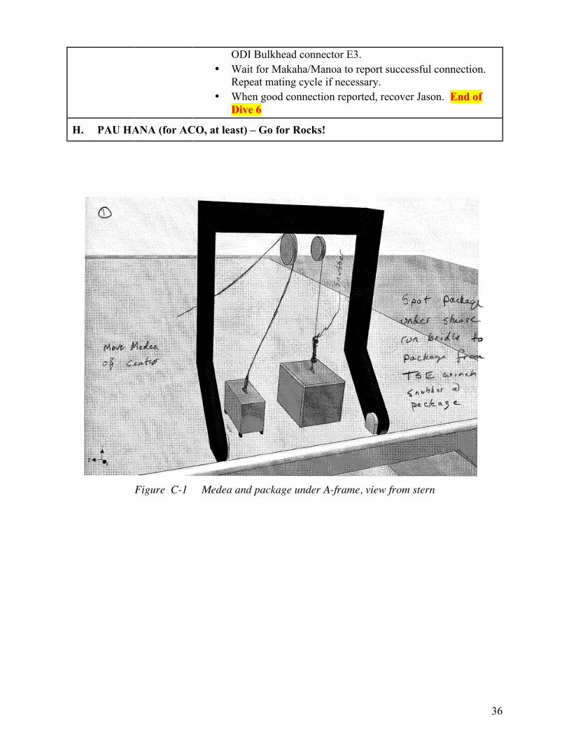
Figure C-1 Medea and package under A-frame, view from stern

37
Figure C-2 Medea and package under A-frame, top view
Figure C-3 Lifting package with the TSE winch
38
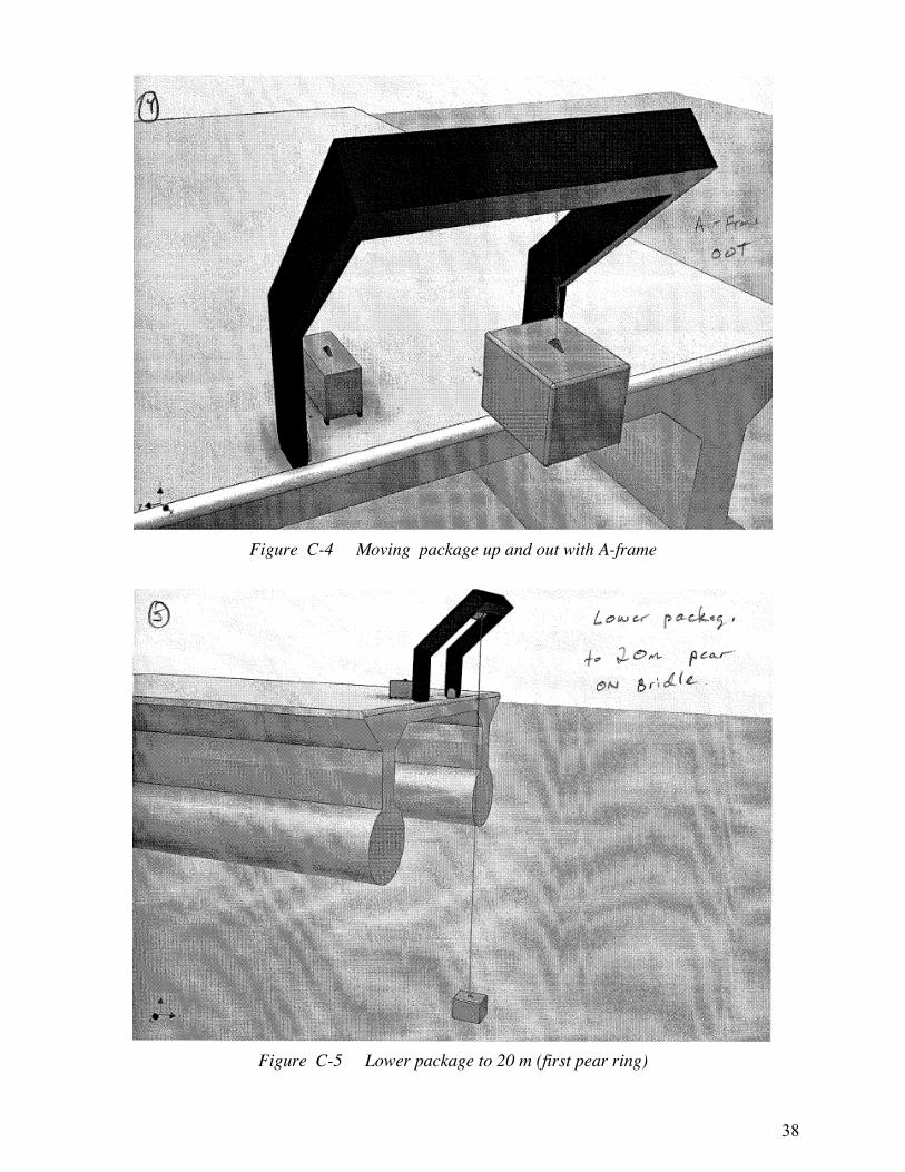
Figure C-4 Moving package up and out with A-frame
Figure C-5 Lower package to 20 m (first pear ring)

39
Figure C-6 Continue lowering package to 20 m
Figure C-7 Move A-frame in and attach Y slip line to pear link at top of 20 m bridle

40
Figure C-8 Transfer load to slip line and 20 m bridle, releasing load on 5 m bridle
Figure C-9 Attach 5 m bridle pear link to Medea; lift Medea

41
Figure C-10 Align Medea above package by adjusting slip line
Figure C-11 Slowly slack and slip Y slip line

42
Figure C-12 Lower Medea and package
Figure C-13 Put Jason over the port quarter with crane (before Medea) and allow to drift aft

43
Figure C-14 Package deployment bridle; snubber in-line at left/package end
Figure C-15 At the bottom
44
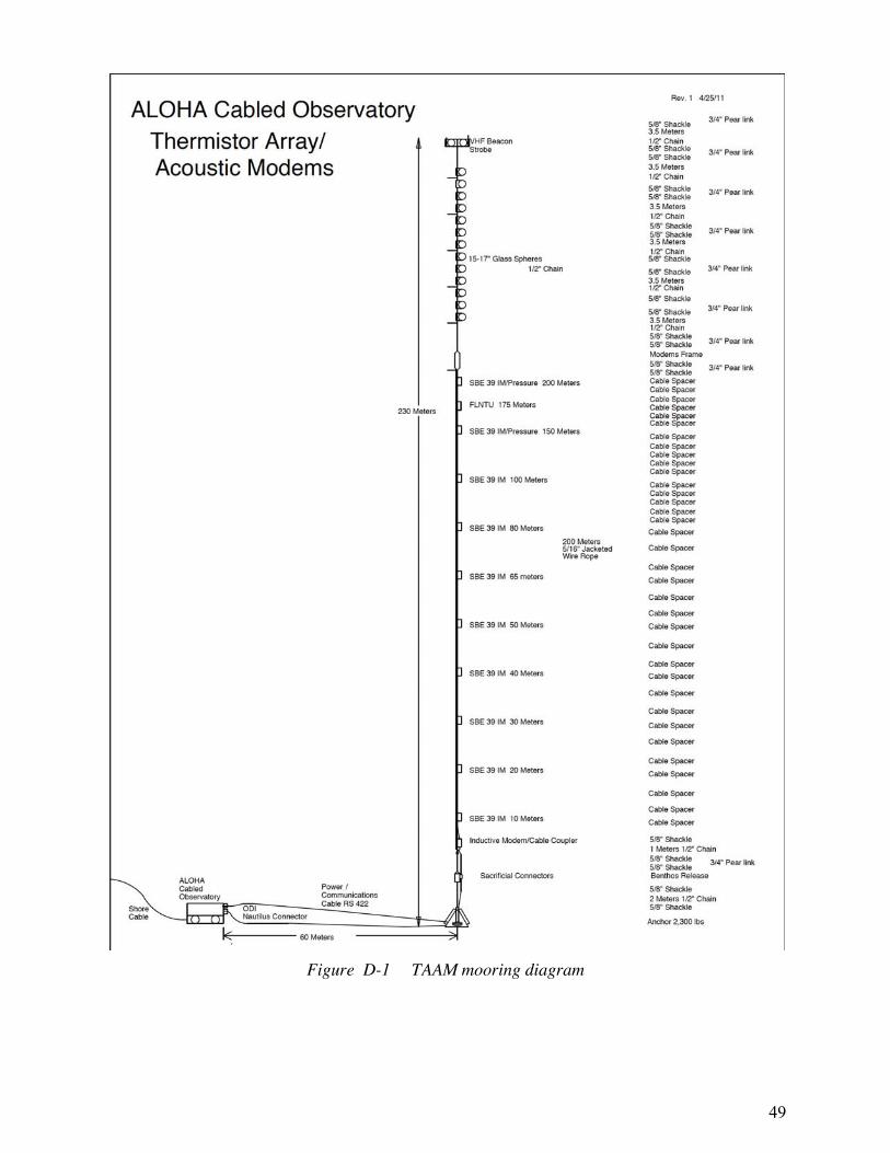
Appendix D – TAAM Mooring
UH/WHOI Thermistor Array/Acoustic Modem Mooring Assembly and Deployment
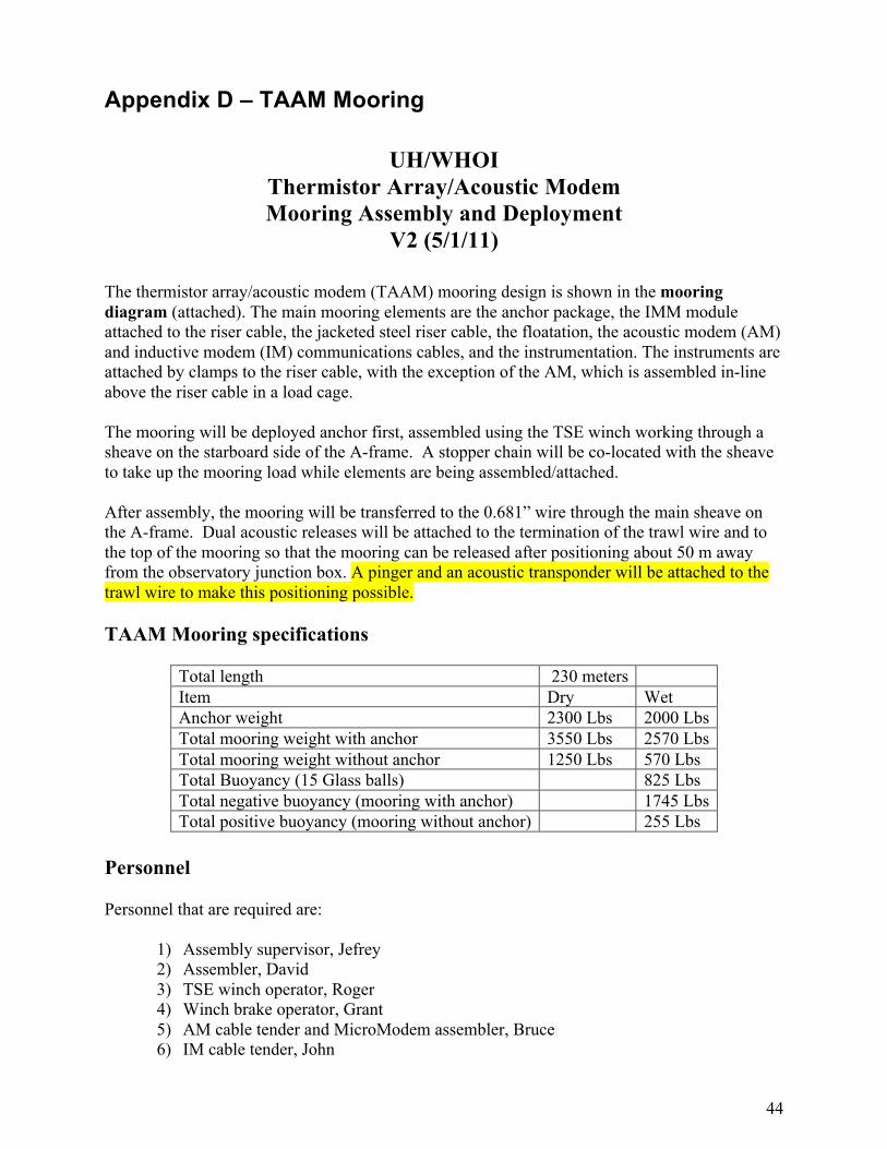
V2 (5/1/11) The thermistor array/acoustic modem (TAAM) mooring design is shown in the mooring diagram (attached). The main mooring elements are the anchor package, the IMM module attached to the riser cable, the jacketed steel riser cable, the floatation, the acoustic modem (AM) and inductive modem (IM) communications cables, and the instrumentation. The instruments are attached by clamps to the riser cable, with the exception of the AM, which is assembled in-line above the riser cable in a load cage. The mooring will be deployed anchor first, assembled using the TSE winch working through a sheave on the starboard side of the A-frame. A stopper chain will be co-located with the sheave to take up the mooring load while elements are being assembled/attached. After assembly, the mooring will be transferred to the 0.681” wire through the main sheave on the A-frame. Dual acoustic releases will be attached to the termination of the trawl wire and to the top of the mooring so that the mooring can be released after positioning about 50 m away from the observatory junction box. A pinger and an acoustic transponder will be attached to the trawl wire to make this positioning possible. TAAM Mooring specifications
Total length 230 meters Item Dry Wet Anchor weight 2300 Lbs 2000 Lbs Total mooring weight with anchor 3550 Lbs 2570 Lbs Total mooring weight without anchor 1250 Lbs 570 Lbs Total Buoyancy (15 Glass balls) 825 Lbs Total negative buoyancy (mooring with anchor) 1745 Lbs Total positive buoyancy (mooring without anchor) 255 Lbs
Personnel Personnel that are required are:
1) Assembly supervisor, Jefrey 2) Assembler, David 3) TSE winch operator, Roger 4) Winch brake operator, Grant 5) AM cable tender and MicroModem assembler, Bruce 6) IM cable tender, John
45
7) Mooring logger, Cammy 8) Instrument staging, Kimball 9) Taggers, OTG 10) A-frame operator, AB 11) Air tugger operators (2) if needed, OTG
Deck layout and preparation Medea will need to be secured forward of the A-frame and away from the cable run from the TSE winch to the A-frame. Two air tuggers with snap hooks should be positioned as shown in the attached deck diagram. These may be needed to limit the movement of the riser cable while instruments are being attached. A cleat will be needed on the deck inboard of the starboard air tugger. This will be used to stop off the mooring with spectra line, and will also be used for a tag line. A cleat inboard of the port A-frame arm, aft of the air tugger, will be used for a tag line. A small block is needed on the A-frame for the Acoustic modem communications riser cable. The bottom end of the chain stopper should be tended out of the way with a line through the cleat on the starboard/inboard side of the A-frame, and made secure to the cleat on deck. A piece of working line will need to be attached to the riser cable termination on the TSE winch and run through the sheave. Anchor module preparation ~ 1 hour The anchor module will be staged in the throat of the A-frame for setup. As shown in the mooring diagram, chain will be attached to the bridle of the anchor, then the Benthos release will be attached above that. A shackle pear link shackle and another shot of chain will follow. The end of this chain will be attached to the riser cable termination after it has been run through the sheave. The total length of this assembly is 20 feet. Two communications cables will be attached to the anchor frame and the first shot of chain. All connections should be shackle-pear link-shackle, with cotter pins in every shackle. All pins should be wrapped with tape. Large end of pear links face up.
1) Shackle 2 m chain to anchor frame chain bridle 2) Shackle Benthos release followed by a shackled 1 m chain above. 3) Connect the observatory communications cables to the sacrificial connectors on the
mooring communications cables [Need to identify clearly which cable is which. Are two half-spools clearly identified?]
4) Wrap the communications cables together with fire hose above and below the connectors and tie wrap [How high above the shackle-pear-shackle connection should the upper wrap extend?]
5) Tie wrap cable bundle to lower chain in two places 6) Run 5/16” wire rope through the A-frame block and shackle to top pear link (do not
pin this shackle)

46
Mooring Assembly
1) Position A-frame directly above anchor module with sheave above anchor shaft and with cable spools oriented fore and aft.
2) Position tag lines 3) The 210 m acoustic modem (AM) communications cable will be handled by AM
Cable Tender leading through the A-frame block. In slow on TSE winch to lift anchor chains off deck
4) Tend anchor chain and mooring comms cable bundle above the anchor until taught and STOP TSE
5) When all on deck are ready, in slow on TSE lifts anchor 1’ off deck, with tag lines stabilizing
6) A-frame full out slow, tag lines out slow and TSE out slow to keep anchor module above deck level and chain below sheave
7) TSE lowers anchor into water 8) Slip tag lines out of anchor frame slowly as anchor enters water to avoid fouling
First stop – secure communication cables ~3 min Once the anchor is in the water, we will want to attach the covered communications cables to the upper anchor chain near the top.
1) In on the A-frame and adjust height with TSE 2) Snatch chain with air tuggers to control movement if needed 3) Tie wrap cable to anchor chain outboard 4) Unhook chain from air tuggers 5) Out on A-frame
Second stop – inductive modem ~10 min
1) Out on TSE; stop when riser cable termination is at deck level 2) In on the A-frame if needed 3) Attach IM pressure housing to wire rope 4) Connect IM cable to pressure housing 5) Clamp IM coupler to wire rope 6) Tie wrap IM cable coupler to wire rope with Tygon tubing as chafe protection 7) Tie wrap cables together to support the IM coupler cable 8) A-frame out
Instrument and cable clamp stops ~1:30 Ten Sea-Bird SBE-39 temperature sensors will be clamped to the rise cable. The top two will also measure pressure. They will communicate with the inductive modem at the bottom of the riser cable. A Wet-Labs fluorometer will be attached at 175 meters. The riser cable has tape marks for instrument stops. The Mooring Logger will have a table of instrument stops (measured length from bottom of riser cable) corresponding to instrument serial numbers. These need to be double checked at the time each instrument is staged, and before it is handed to the assembler. Rubber clamps will hold the AM cable to the riser cable. These are tie wrapped vertically around the separation between the two cables. All tie wrap ends should be clipped.

47
Note that the top termination of the riser cable is attached to the working cable on the TSE winch with a shackle-pear link-shackle, and this will have to go through the sheave and stopped off.
1) Out on TSE to next instrument stop marked on riser cable, with AM cable being tended through snatch block
2) Stop at first instrument marking. 3) Attach SBE-39: attach instrument clamp then inductor clamp. Start each screw with
hand tool. 4) Place rubber cable clamps above and below instrument and tie wrap. 5) Out on A-frame to clear instrument 6) Out on TSE 7) Stop at intermediate cable clamp position(s): ~5 m apart (one between closely spaced
instruments and three or four between widely space instruments) 8) Repeat from 1) until all ten SBE-39s are attached to the riser cable
Micro Modem stop and assembly 1) Make sure that the AM cable is well tended and avoid crushing against ship 2) At the top of the wire rope riser cable will be a shackle and pear link. Stop off the
mooring by shackling into the vertical chain stopper so that the pear link is about 1’ above deck.
3) Remove working cable from the mooring, being careful to prevent the cable from going back through the sheave. Put a line through it and tie it off against a cleat.
4) Shackle the bottom end [pressure case end is down] of the Micro Modem cage to the pear link
5) Shackle 4-meter chain to top of Micro Modem cage. 6) Shackle working wire rope to top of chain shot with pear link between shackles 7) In on TSE to lift cage off deck and make vertical 8) Hold bottom of cage at chest level 9) Dress the excess cable into a service loop tie wrapped to Micro Modem cage 10) Plug the AM cable into the Micro Modem pressure housing 11) Out on A-frame 12) Out on TSE to put Micro Modem cage into the water 13) Stop TSE with pear link just above deck level 14) A-frame in 15) Stop off mooring with chain stopper
Glass ball stops and assembly There are 5 3.5 meter shots of chain with 3 balls on each and one 3.5m shot with 3 balls. These will be shackled together with a pear link between shackles. Note that the top two glass balls are bolted together and have a radio and strobe attached outboard from the chain. We have to take care about the radio antenna.
1) Shackle first chain of balls to pear link 2) Shackle working cable into end of chain shot with pear link 3) In on TSE to lift balls from the deck 4) Remove chain stopper 5) Out on A-frame 6) Out on TSE, stop with pear link just above deck

48
7) A-frame in 8) Stop off with chain stopper 9) Repeat 1-8 three more times 10) Connect Benthos release to top links of mooring chain 11) Connect top of release to the trawl wire
Transfer load from TSE to trawl winch The mooring has to be handed off to the trawl winch for lowering to the seafloor. The JASON sheave in the middle of the A-frame has to be tended out of the way for the transfer.
1) In on trawl winch to lift release off of deck to tension and STOP 2) Out on A-frame 3) Out on TSE to transfer load to trawl wire 4) A-frame in 5) Disconnect working wire rope 6) A-frame out 7) Out on trawl wire until glass balls are in water 8) A-frame in 9) Clamp acoustic transponder on trawl wire 10) A-frame out 11) Lower transponder below stern and stop 12) A-frame in 13) Clamp 12 kHz pinger to wire 14) A-frame out 15) Lower an additional 20 meters and attach cable grip and shackle on the recovery
weight. 16) Lower the mooring to near bottom, position within 60 meter of the observatory
junction box and release.
49
Figure D-1 TAAM mooring diagram

50
Appendix E – Ka‘ena Ridge Operations
Figure E-1 Locations of possible cables in the Ka‘ena Ridge region

51
Appendix F – Bathymetry in the ALOHA area If there is time available during the cruise, additional deep multibeam bathymetry data may be collected. There are several areas where this would be useful. Collecting this data will naturally depend on evaluating other competing tasks and priorities, on time available, ship location, etc. See Figure F-1 for reference.
The first priority would be to refine the map of the northeast Kauai ridge to determine the controlling sill depth on that side of the Kauai Deep. The controlling sill depth is the shallowest point along the deepest channel connecting the neighboring basins. In other words, we would like to find the location, extent and depth of the saddle point.
The two sill areas of interest are north of Kauai and around the Oahu Seamounts (red circles in Figure F-1). In the latter area, we would like to know the passages through which cold Maui Deep water finds it way into the Kauai Deep. In some places, there are no multi-beam data. In some others, the data are sparse and you can see on more detailed charts with the raw data the ship tracks with offsets. The high-resolution bathymetry that is available in some places arises from multiples sources and sophisticated merging analysis, with uncertain uncertainties.
Of secondary importance would be to fill in the few obvious, larger areas with no swath data.
Figure F-1 Bathymetry around Station ALOHA (red star). Circles denote sill areas.

52
Appendix G – Cruise Participants and Contacts List
Name Position Email Phone Cruise Participants UH/ACO
1 Bruce Howe Chief Scientist [email protected] Cell: 808-469-0553 Off: 808-956-0466 Hm: 808-888-0665
Iridium: 011-8816-922426745
2 Roger Lukas Scientist [email protected] Off: 808-956-7896 3 Grant Blackinton Engineer [email protected] Cell: 206-579-7738 4 Jefrey Snyder Engineer [email protected] Lab: 808-956-7931 5 Cameron Fumar Scientist [email protected] Off: 808-956-8082 6 John Yeh Technician [email protected] Cell: 808-230-4206 7 David Hashisaka Technician [email protected]
UH/Ka‘ena
8 John Sinton Scientist [email protected] Off: 808-956-7751 9 Doug Pyle Scientist [email protected] Off: 808-956-9697
10 Deborah Eason Post-doc [email protected] Off: 808-956-5036 11 Mary Tardona Student
WHOI/Jason
12 Casey Agee Navigator 13 Scott Hansen Pilot 14 Matt Heintz Expedition
Leader, Pilot [email protected] 508-289-3426
15 Hugh Popence Navigator 16 Korey Verhein Navigator [email protected] 508-289-2273 17 David Walter Engineer [email protected] 508-289-2273 18 Jonathan Miller Engineer 19 Baxter Hutchinson Enginner [email protected] 508-289-3885 20 Akel Kevis-Stirling Pilot 21 James Pelowski Data Manager
OTG
22 Vic Polidoro Technician [email protected] 23 Trevor Young Technician
Contacts UH/ACO Fred Duennebier Scientist [email protected] Cell: 808-398-4828 Dave Karl Scientist [email protected] Off: 808-956-8964 Jim Jolly Engineer [email protected] Lab: 808-956-2488
Cell: 808-392-4784 Jim Babince Technician [email protected] Lab: 808-956-2876 Kimball Millikan Engineer [email protected] Off: 808-956-3643 Mario Williamson Machinist [email protected] Shop: 808-956-7304

53
Brian Chee Engineer [email protected] Off: 808-956-5797 David Parry Engineer Sonicwall Fernando Santiago-
Mandujano Scientist [email protected] Off: 808-956-7000
Joseph Gum Student [email protected] Karynne Morgan Project Asst [email protected] 808-956-6036 Kellie Terada Project Asst [email protected] 808-956-4101 Makaha Cable Station
– ACO 808-696-1904
Makaha Cable Station – AT&T
[email protected] 808-696-4224
Wayne Yamamoto Manager [email protected] 808-696-2777 UH/Marine Center Stan Winslow Marine
Superintendent [email protected] Off: 808-842-9814
Gray Drewry Port Master R/V kilo Moana
[email protected] Cell: 808-864-0122
Ross Barnes Port Operations Manager
[email protected] Off: 808-842-9815 Cell: 808-864-0122 Cell: 808-294-6915
Rick Mayer Master R/V kilo Moana
WHOI/Jason Catherine Ottinger Operations
Manager [email protected] 508-289-3445
Jim Varnum
54
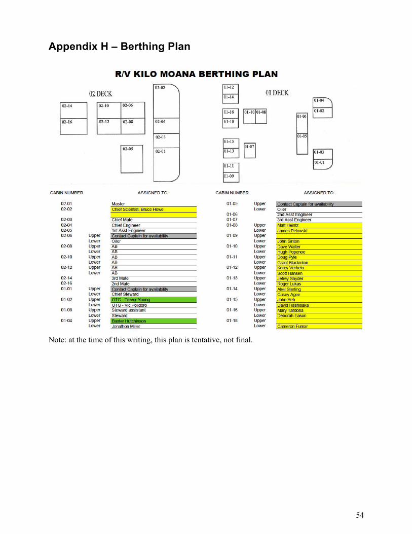
Appendix H – Berthing Plan
Note: at the time of this writing, this plan is tentative, not final.

55
Appendix I – Acronyms and abbreviations 12E Electrical connector with 12 electrical circuits 2E ODI NRH Connector with 2 electrical circuits and 4 optical circuits 4E Electrical connector with 4 electrical circuits ACO ALOHA Cabled Observatory ACP Acoustic current profiler AMM Aloha Mars Mooring Secondary Node CAM Camera Tripod CTDO2 Conductivity, temperature, depth, oxygen sensor package DMAS Data Management and Archiving System DP Dynamic positioning EC Environmental Cover – protective cap for unconnected ODI bulkheads EM Electrical-Mechanical EO Electrical-Optical EOM Electrical-Optical-Mechanical HEM Hydrophone Experiment module, resides on JBOX HOT Hawaii Ocean Timeseries IM Inductive Modem JBOX Frame with junction box and HEM with cables and connectors NRH Nautilus Rolling Hybrid – optical and electrical ODI connector NTP Network Time Protocol OBS Observatory ODI Ocean Design, Inc. wet mateable connector PBOF Pressure balanced, oil filled PMACS Power Management and Control System PPF Parking Position Frame – 5 ODI 12E pin protecting dummies PPS Pulse Per Second (GPS-derived precise timing signal) ROV Remotely Operated Vehicle SIIM Science Instrument Interface Module SMF Single mode fiber SNC Secondary Node Controller SNMP Simple Network Management Protocol TF Termination Frame