15 of ’145 seriesa .--.:.:. -----.: a---- ----- +* . - .,- - … kidde nuclear laboratories, inc....
TRANSCRIPT

. ,. =
LA--1624,. . ..
. .. . ..,.. .... .. .
ikpy 15
seriesA
of ’145.. .. ..-- .:.:. ----- .:A---- -----
—+* . . .. . - .,- --=:...<> .-2A . ----
..-
.. . .—+. =—.
,1:
<
.:
,.
I
1-.;.”.
-:;.I
I
i.i“,
I
I.,
.,
i,.
!,-
,.
I
,.,.
-—....—- ----- ---= -.=+ .. . .. . . T. .. .. . ... ..
-. ,..=...._. -.._ ..... .. . .-. —.. .....’.. . . . . . . . . .
I. . . . . . . . . . . . .. . ..., . . . .. -. . . . ...
.
..2._. _.A. —.-— . .. —.-— ------- .. —----- -------- .- —— -—---- ,-
—-.——.. —-
APPROVED FOR PUBLIC RELEASE
APPROVED FOR PUBLIC RELEASE

I
LOS
Report writtemJanuary 1953
.. ...
~== uNCklFJE~%. ..—.
ALAMOS SCIENTIFIC LABORATORY
of the
UNIVERSITY OF CALIFORNIA
PUBLICLYRELEASABLEPer #?&k &+s FSS- 16 Date:
, CIC- 14 Date:
A7”/3+?T
M J’ ‘m.-
LA- 1624
AVERAGE FISSION CROSS SECTION OF U238 FOR FISSION NEUTRONS
by
R. B. Leachman and H. W. Schmitt
PHYSICS AND MATHEMATICS
UNCLASSIFIED.,-_’”------..,-%.-7=.-———————
APPROVED FOR PUBLIC RELEASE
APPROVED FOR PUBLIC RELEASE

-...—.
PHYSICS AND MATHEMATICS
Distributed A~ll 2:1954Los Alamos Report LibraryAF Plant Representative, BurbankAF Plant Representative, SeattleAF Plant Representative, Wood-RidgeANP Project Office, Fort WorthArgonne National LaboratoryArmed Forces Special Weapons Project (Sandia)Army Chemical CenterAtomic Energy Commission, WashingtonBattelle Memorial InstituteBrookhaven National LaboratoryBureau of ShipsCalifornia Research and Development CompanyCarbide and Carbon Chemicals Company (c-31 Plant)Carbide and Carbon Chemicals Company (K-25 Plant)Carbide and Carbon Chemicals Company (ORNL)Carbide and Carbon Chemicals Company (Y-12 Plant)Chicago Patent GroupChief of Naval ResearchColumbia University (Havens)Commonwealth Edison CompanyDepartment of the Navy - 0p-362Detroit Edison CompanyDirectorate of Researchdupont Company, AugustaFoster Wheeler CompanyGeneral Electric Company (ANPP)General Electric Company, RichlandGoodyear Atomic CorporationHanford Operations OfficeIowa State CollegeKlrtland Alr Force BaseKnolls Atomic Power LaboratoryMassachusetts Institute of Technology (Kaufmann)Monsanto Chemical CompanyMound LaboratoryNational Advisory Committee for Aeronautics, ClevelandNational Bureau of Stan&rdsNaval Medical Research InstituteNaval -search LaboratoryNew Brunswick LaboratoryNew York Operations OfficeNorth American Aviation, Inc.Nuclear Development Associates, Inc.Patent Branch, Wash@tonPhillips Petroleum CompanyPratt & Whitney Aircraft Division (Fox Project)RAND CorporationSandia CorporationUSAF-HeadquartersU. S, Naval Radiological Defense LaboratoryUCLA Medical Research Laboratory (Warren)University of California Radiation Laboratory, BerkeleyUniversity of California Radiation Latmratory, LivermoreUniversity of RochesterVitro Corporation of AmericaWalter Kidde Nuclear Laboratories, Inc.Westinghouse Electric CorporationYale UniversityTechnical Information Service, Oak Ridge
UNCLASJirlED
LA- 1624
1-2021222324
25-323334
36-3’738
39-41
43%445
46-4’748-5354-5’7
58596061826364
65-6’768
69-71‘72-7576-77
787980
81-848586
87-89909192
93-9495
96-9798-100
101102
103-10610’7108109110111112
113-117118-120121-122123-124
125126-129
130131-145
-2-
-. UNCLASSIFIED-
APPROVED FOR PUBLIC RELEASE
APPROVED FOR PUBLIC RELEASE

__—-———-... .
ABSTRACT
By means of measurements with a double ionization chamber,
the average fission cross section of U238for neutrons from the
fission of. U235 was determined in terms of v, the average number235
of neutrons per fission of U . The number of fissions of U238
was measured in one of the ionization chambers while the number of
fissions from the fission neutron source of U235was measured in the
other chamber. In the nine runs made to determine the cross sec-
tion, a variety of different methods was used to determine the number238
of fissions and the mass of U . The weighted average of these runs
gives 6f(28) = (0.756 * 0.008)/v barn or, if the most recent value
v = 2.48 * 0.03 is used, 6f(28) = 0.305 + 0.005 barn.
-3-
—_.
%“
APPROVED FOR PUBLIC RELEASE
APPROVED FOR PUBLIC RELEASE

c,,,,,,,,,,,,.._..1. Introduction
The average cross section for the fission of U238
can be written
m
5.f J dE#(E#f(En),0
238 aswhere 6f(En) is the fission cross section of U
N(En) is the probability of a neutron with an energy
m
J dEnN(En) = 1.
0
Data are available for the calculation
and Watt2 is used in Eq. (1) wtth the
by neutrons from the fission of U235
(1)
a function of the neutron energy E., and235
11
En from the fission of U . Thus:
(2)
iof 6= from Eq. (l). If N(E_) as measured by NeresonL
J. 11
61(E-) data compiled by Nyer3 the value ?7S. 0.28 barn
is obtained. However, the experiments; determinations of 5f(En) used in this c~culation of df
from Eq. (1) involve absolute determinations of neutron flux. Principally because of this, there
exists in this method a possibility of significant error in 6 f(En) and, therefore, in this calcu-
lated value of Gr
The present determination of Ff was designed to make use of what seem to be the most
reliable data on absolute neutron measurements. To obtain the neutron source strength it was
decided to determine the number of fissions in a piece of U235
, which served as a fission
neutron source. The factor converting the number of UZJ5 fissions to the number of fission
neutrons is v. It is believed that the uncertainty in v is as low as that of any other measure-
ment of neutrons in this energy region. In order to conform with this accuracy of neutron
measurement, the present equipment was designed so that the composite of other uncertainties
is not greatly in excess of the 1.2 percent uncertainty in v.4
2. Method
Since only the fission neutron source stren@h Q is determined by observations of the number
of U235fissions, it is required of the geometry of the apparatus that the neutron flux nv on
the U238 be accurately determinable from Q. For this reason, the geometry chosen for the
apparatus was hemispherical wtth the U235 neutron source at the center of the hemisphere238
containing the U .
Illustrated in Fig. 1 are the essential components of the apparatus, while Fig. 2 is a
detailed illustration of the ionization chambers. As can be seen in Fig. 1, thermal neutrons
UNCLASSIFIED
APPROVED FOR PUBLIC RELEASE
APPROVED FOR PUBLIC RELEASE

....-
:. .-.”
.-
-5-
.——
——
—.__..._.._
.—.—
.——
.....
.—..-.
APPROVED FOR PUBLIC RELEASE
APPROVED FOR PUBLIC RELEASE

-1G-1uw1-U)
ueu
_..—
....—
—,m
,..->.
!..-—
.----
------
/
/
Ei=iiz
-6-
---
APPROVED FOR PUBLIC RELEASE
APPROVED FOR PUBLIC RELEASE

to induce fission in the U235 neutron source were provided by the Los Alamos Water Boiler
reactor. With the thermal column of the reactor as illustrated, the thermal flux upon the U235
was 3(107) neutrons/cm2/sec. This thermal flux was incident upon a U235
metal disc source
of 7/8 in. diameter. As seen in Appendix I, the effective flux from the disc source on the U238
deposit is only about 1 percent greater than that from a point source of the same Q placed at
the center of the hemisphere. Similarly, it can be shown (Appendix II) that extreme nonuni-
formities in the thickness of the U238 deposit lead to corrections that are negligible. If the
fission neutron source were a point, the cross section would be determined by
vN25 M28 (6.023) (1023) Gf
’28 = 94rr2 (238)
238‘here ’28 and ’25 are the number of fissions in the U and U235 , respectively, r isradius of the hemisphere in centimeters, and M
28 is the mass of U238 in grams. With
disc source, we have
N (6.023) (1023)Zg =4n (238) 1 [: ln(~)+ ln(~]$’28’25 v 5f ~
(3)
the
the
(4)
where a is the radius of the disc source in centimeters.
Shown in Fig. 2 are the details of the chamber used to determine the quantities N.,
’28”The UA”O in the form of U34“008 of 110, 000:1 isotopic abundance was on a thin aluminum
hemisphere which was concentric with another thin but larger aluminum hemisphere. The two
aluminum hemispheres constitute an ionization chamber which detects the U238fission frag-
ments. Cylindrical extensions spun on the hemispheres made possible detection of all fissions.
The U238 was confined to the hemisphere itself.
To reduce the thermal neutron fission of the U235 238present in the U , cadmium shields
were placed between the source of thermal neutrons and the hemisphere containing U238. These
shields, however, did not eliminate the background fission rate in the hemispherical chamber.
Therefore it was necessary to measure the background by removing the U235source and
counting only the fissions induced (a) by the gamma rays from the reactor and from neutron
capture in the equipment, (b) by fast neutrons from the reactor, .and (c) by thermal, leakage
neutrons on the U235 present in the U238 deposit.
As seen in Fig. 2, the disc source, cut from rolled U235metal of either 94.12 or 93.26
-7-
.. .—I .—— — .: .L—
APPROVED FOR PUBLIC RELEASE
APPROVED FOR PUBLIC RELEASE

— _._.. -_— - _ -----_. . . . . .
percent isotopic abundance, * was attached to the center of a 1/32 in. thick, 4 in. diameter
dural plate and was mounted in a position concentric with the hemispherical chamber. On the235
other side of the dural plate and mounted just opposite the U source was a thin monitor
foil consisting of thin platinum on which was deposited a known mass M25m of U235
in the
same diameter as the source. The thinnest deposit used in the monitor in these measure-
ments was about 0.1 W, while the heaviest used was about 200 ~. The thinnest source used
was about 0.001 in. thick and the thickest used was about 0.008 in. thick with masses M of
0.21 gm and 1.46 gm, respectively. Since the masses of both the U235disc and the U2%
monitor deposit were khown, the number of fissions in the monitor was used in one deter-235
mination of the total number of U fissions in each disc source. The fission fragments
the monitor were observed in the ionization chamber formed by the dural plate mentioned
above and a similar dural plate parallel to it.
Since the attenuation of the thermal neutrons in the disc sources was appreciable, a
from
correction was necessary. Measurements to determine this correction to better than 1 percent
accuracy were made in a parallel-plate, double ionization chamber. Such accuracy was achieved
by counting fissions from two thin monitor foils of unknown amounts of U235 in the two
chambers. These monitor films on platinum, which was black to fragments, sandwiched theU235
metal discs being measured. Two sets of counts were used, the direction of the neutron
beam being perpendicular to the foils but opposite in direction for the two sets; thus knowledge
of the monitor foil masses was umecessary.
In these measurements of Gf(28) an effort was made to have multiple, independent deter-
minations of the quantities in Eq. (4) wherever feasible. The mass of the U238
deposit 5 on
each of the three aluminum hemispheres used for the various runs was determined by.
(a) The mass difference between the aluminum hemispheres with and without the U323808
deposit;
(b) The rate of alpha-decay of the U238; and
(c) A calorimetric analysis6 of the uranium on the hemispheres.
In several runs, the number of U235
fissions in the source was determined by a radio-
chemical analysis7 of the Meg’235
content of the bombarded U disc. In every run, the number
of U235fissions in the disc was determined from the number of fission fragments detected by
the parallel plate ionization chamber and the relative masses of U235
in the monitor and disc
*After the measurements had been completed and the U235metal had been reprocessed, it
was learned that the pieces of metal used were of either 93.26 or 94.12 percent abundance.Unfortunately, the inventory of these metal pieces was not in good order, wid while it isalmost certain that the metal pieces used were of 93.26 percent abundance, there exists thepossibility that some were of 94.12 percent. The value used in the calculated results is 93.26percent.
-8-
.—. .—
. .--, --- >-.-—-———-——
APPROVED FOR PUBLIC RELEASE
APPROVED FOR PUBLIC RELEASE

source.‘he ‘ass ’25m
of the U235 content of the monitor was determined by one or more
of the following methods:
(a) Fission counting of the U235 deposit in comparison with a standard U235
deposit;
(b) The mass difference between the platinum foils with and without the U32350Q deposit;
and/or
(c) A calorimetric analysis of the uranium on the platinum foil.
Since the standard U235
deposits used in (a) amounted to roughly 0.1 #g,235
satisfactory for U deposits of about 1 pg or less. On the other hand,
this method is most
methods (b) and (c)
require deposits of 100 p.g or greater for 1 percent accuracy. Thus, small deposits were
measured only by method (a), and larger deposits only by methods (b) and (c).
The numbers of observed fission fragments from the U235
monitor in the parallel plate238
ionization chamber and from the U deposit in the hemispherical ionization chamber were
recorded by standard LOS Alamos electronic equipment. Potentials of roughly 200 volts supplied
by batteries were applied across both chambe~s. The pulses from each chamber were fed to
two standard Model 101-A amplifiers and the output from each of these went to a standard
Model 700 or 700-A scaler. This provision of duplicate amplifiers and scalers for each chamber
made possible an easier detection of malfunctioning electronic equipment. Background fission
counts from possible uranium contamination of the chamber components were minimized by
having the U235 238
plate, and U hemisphere, and the cadmium shield all at the same negative
potential, while the collecting plate and hemisphere were near ground potential.
3. Results
Several corrections of several percent or less for neutron absorption and neutron scattering
must be applied to Eq. (4). Corrections are necessary for absorption and scattering of thermal235
neutrons in the platinum and dural between the U deposit and the U235
disc. Equation (4)235involves only the direct flux of fission neutrons from the U disc to the U
238deposit. Cor-
238rections are necessary because fission neutrons were, in addition, scattered to the U by
the reactor face (Appendix 111), the outside case of the chamber, and the various hemispheres
within the case (Appendix IV). In addition, the absorption of the fission neutrons by the
cadmium and the inner aluminum hemisphere was taken into account. The largest of these
corrections is 2 to 3 percent for the scattering of neutrons from the hemisphere containingU238
; that is, a greater effective thickness of U238
is “seent’ by the deflected fission neutrons
than is “seen” by the unscattered neutrons. Expressions for this correction are developed and
applied in Appendix IV.
In order to test qualitatively the validity of this scattering calculation, two different
-9-
—-.-z—. –.-
—..—=.
APPROVED FOR PUBLIC RELEASE
APPROVED FOR PUBLIC RELEASE

~!=’.—---- .—.—-_._______.—thicknesses of aluminum hemisphere were used in the cross section measurements. The re-
sults, as seen in Tables 1 and 2, indicate that an error in these calculations of as much as
several percent change in cross section is very unlikely. A measurement of the increase in
the number of U238
fissions due to the fission neutrons back-scattered from the copper and
steel outside case of the ionization chamber was made by comparing the number of U238
fissions when a double thickness of steel and copper was used with the number obtained when
the original thickness was used. The percentage increase measured was 0.53 * 0.3, while,
as shown in Appendix IV, the calculated increase due to the neutrons back-scattered from the
steel and copper was 0.51 percent.
In the various runs, the ionization chamber was filled to 6 + 1 lb gauge pressure of
tank argon. This pressure caused a bulging outwards of the dural base plate of the ionization235
chamber and, as can be pictured from Fig. 2, the U disc is displaced from the center of
the hemispheres. The amount of the displacement was 0.018 in. and this caused a calculated
0.6 percent decrease in the average fission neutron flux on the U238
compared with the flux
from a centered source.
It was expected that the removal of the U235
disc would reduce the background by the238
amount of the U235
photo fissions from the U fission gamma rays. On the other hand, the
background would be increased by the increase of the thermal flux on the cadmium giving rise
to an increased number of capture gamma rays and leakage neutrons on the U238and its U235
impurity. To determine the validity of the measured backgrounds, tests were made qualitatively
to determine these effects. Gold or aluminum-boron, both of the same opacity to thermal235 235neutrons as a U disc, was substituted for the U disc. Aluminum-boron has capture
gamma rays of 0.51 Mev, whereas gold has capture gamma rays of about 8 Mev. The photo
fission threshold energy is about 6 Mev. Since essentially all fission gamma-ray energies are
less than 5 Mev,8 235it would be expected that the true background with the U disc present
would be quantitatively between that with the gold and that with the aluminum-boron. The runs
made showed that the background with the gold disc in the position of the U235disc was 1.0 +
0.5 percent greater than with no disc. Similarly, the background with the aluminum-boron disc
was 0.3 * 0.5 percent less than with no disc. These results indicate that the backgrounds with235
and without the U disc are the same within the accuracy of the whole experiment. Since the
background U238 fissions are always less numerous than the U238fissions induced by fission
neutrons, the uncertainties in the former are less important than in the latter.
Having determined the neutron scattering and absorption corrections to Eq. (4), we now
consider the determination of the quantities N25, N28, and M28, quantities which in this ex-
periment vary from run to run. As mentioned in the previous section, except for the three
Mo’g analyses, the quantity N25 is determined from
-1o-
.—.. .— ‘-———
APPROVED FOR PUBLIC RELEASE
APPROVED FOR PUBLIC RELEASE
’25 = ‘N25m ’25 ’25 ‘d)’M25m’
where in Eq. (5) N25 and N25m are the numbers of fissions
respectively. The effective transmission T25 is the average235
into all depths of the U disc as calculated from the total
(5)
in the U235 disc and monitor,
transmission of thermal neutrons
absorption measurements described
in the previous section. The transmission Td is the transmission of thermal neutrons through
the dural plate of the parallel-plate ionization chamber. Thus, in these determinations of N25
the quantities N25m, M25, M25m, T25, and Td must be considered. The transmission Td
is near unity and is calculated in Appendix V.
The number of fissions N25m and N28 is determined from linear extrapolations to zero of
the integral bias curves obtained from the respective ionization chambers. To this extrapolated
number of fissions is added the <1 percent of the fission fragments stopped in the U308
coatings, as calculated in Appendix VI. Included in Table 1 are the plateau corrections applied
to the number of fissions observed in the ionization chambers at the fixed bias used during
the runs. The variation of plateau corrections is mainly due to the different gas fillings of
the chamber.
The most accurate determination of the quantities under consideration seemed to be that
‘f ‘he ‘ass ’28of the U238 deposits. The mass M28 was first determined by the mass dif -
ference between the painted and unpainted aluminum hemispheres. However, since the aluminum
hemispheres could only be heated to about 300°C, the uranium nitrate probably was not com-
pletely converted to the oxide so that the masses obtained could be used only in a relative
sense. For this reason, the weights were used only for a qualitative check on the other deter-
minations.
When the hemisphere wtth the U238 deposit was mounted in the ionization chamber, the
alpha-decay rate was measured as a determination of M28. This alpha counting is essentially
in 2n geometry and corrections were necessary for the loss of alpha particles in the U238
and
for back-scatteringg of alpha particles from the aluminum backing. The U238 alpha-decay
half-life applicable for this type of measurement was determined by a carefully controlled
series of measurements. In these measurements foils of which two independent determinations
(calorimetric and weighing after heating to 800°C) of the mass of the 100,000:1 U238 were
made were alpha-counted in 27r geometry. The alpha-decay half-life was so measured to be
4.56 ~(lOg) years, which is excellent agreement with the half-life calculated from the U234
half-life and the U234/u238 10abundance ratio of natural uranium as gtven by Fleming et al.
However, it is in poor agreement with the directly measured value (4.49 + 0.01) (109) years. 11
Although on the basis of the present careful measurements it is believed the latter half-life
value is in error, these measurements were not primarily intended to be an absolute
-11-
APPROVED FOR PUBLIC RELEASE
APPROVED FOR PUBLIC RELEASE

.
dzmN.
00.mo.x
”
mmcom.
0rs
mm.
0m000“
mnn
-12-
0
Ind“
o+“
In*“o*.
2s0.0.
00dltn
law
W*
.Hcom
—.-.
-——
—.
.—
—=
._
—.
....-——
APPROVED FOR PUBLIC RELEASE
APPROVED FOR PUBLIC RELEASE

.—
-. . .. ..- -——.
determination. Instead, because of uncertainties in the back-scattering and alpha-absorption
corrections, they gave a quantity applicable to the hemisphere measurements in question.
After use in the cross section experiment, the uranium deposits on the aluminum hemi-
spheres were determined quantitatively by the calorimetric method. Except for the case of
one gross, unexplained error, the agreement between calorimetric and alpha-particle deter-
minations was within 0.1 percent.
Aside from the uncertainty in the value of v, probably the greatest uncertainty involved
in the present measurements is in the measurements of N25”
The direct determination by
Mo9’ analysis has an accuracy of + 5 percent or better. In the present experiment, the re-99 99suits of the Mo analysis were corrected for the calculated number of Mo atoms that es-
caped from the discs as fission fragments. The major uncertainty in N25 as determined from
Eq. (5) is in the monitor mass M25m. Comparison fission counting of the monitor foils suf-
fered from the disadvantage that the foils in question underwent at least two mountings, one
in the comparison chamber and the other in the fission chamber. There was, therefore, the
possibility of contamination and crinkling of the foil. In addition, in the comparison fission
counting the integral bias curve of the thin standard deposit had less slope that that of the un-
known, which generally had a thicker deposit on a less smooth foil. These slopes produced a
small uncertainty.
When calorimetric and weighing analyses were used to determine M25m, a compromise
between the following considerations was required: (a) a large M25m for accurate mass deter-
mination, and (b) a small M25m for a fission counting rate compatible with the resolving time
of the electronic equipment. As a result, the 74- to 175- p.g monitor masses used were near
the lower limit of the weighing and calorimetric methods of analysis. Controlled tests with
other foils showed a reproducibility of about + 2 pg in weighing after repeated beatings to
800°C, which converted the uranium to U308. For these monitor masses the accuracy of the
calorimetry method is 2 to 3 percent, whereas@ for the 46- to 60- mg masses on the hemi-
spheres the 95-percent confidence interval is ● 0.5 percent.
Table 1 is a summary of the results of this experiment including the corrections listed238in the previous sections. The characteristics of the U deposits and the U235
monitor foils
are contained in Tables 2 and 3, respectively. As can be seen in Table 2, the agreement
between the alpha-counting and calorimetric analyses for hemispheres I and 11 was excellent.
The weight determination was rc)ughly 7 percent high in these cases and also in other test cases.
The weight determination in the case of hemisphere III indicates that the U238mass determined
by calorimetry is correct and
reason fcr tkis error was not
that the mass determined by alpha counting is in error. The
discovered.
-13-
—.——— . .
APPROVED FOR PUBLIC RELEASE
APPROVED FOR PUBLIC RELEASE

-.-. _——.-. .
_.—~._....--. —
TABLE 2
CHARACTERISTICS OF THE U238
Mass determinations by the various methods are238
are the calculated percentage of the total U fissions induced by fission neutrons
from the aluminum backing of the hemispheres. The effective scattering thickness
average thickness of the aluminum hemisphere.
HEMISPHERES
given. The fissions from scattering
scattered
is the
Effective FissionsU238
MassU238
MassScattering from by by Alpha-
Hemisphere Thickness Scattering Calorimetry CountingNumber (in. ) (%) (mg) (mg)
I 0.022 2.27 60.6 60.68
II 0.022 2.2’7 65,6 65.5,8
III 0.038 3.4’7 46.6 50.35
4. Conclusions
U238Mass
byWeighing
(mg)
64.9
69.5
50.2
It is evident that the quantity having the largest uncertainty in these measurements is
‘25m” Consequently, to determine the best value of 6f(28), the values of Ff from each in-
dividual run were weighted according to the number of independent determinations of M25m.
We have rather arbitrarily assigned the same uncertainty to each method of determination.
AS a result, the weighting of runs relative to those of one determination of M25m is K for
two determinations and &for three determinations. Thus, runs 4, 5, and 8 had a weight of
1; runs 1, 2, and 3 a weight of a; and run 6 a weight of ~ Run 7 was omitted in the cal-
culation of a weighted average because of an uncertainty in
With such a combination of the results listed in Table0.756 + 0.008
barn, where the uncertainty is the standardv A
its background run.
1, the best value is i5f(28) =
devtation of the mean. If we use
uncertainty is not clear, we obtain
the 0.28 barn from the reported
the latest valueq v = 2.48 + 0.03, where the meaning of the
6f(28) = 0.305 + 0.005 barn.
The present value of tif(28) is significantly larger than
data and Eq. (l), but the difference is probably not larger than the uncertainty in the values
of 6f(En) used. In contrast, a more recent calculation of Gf(28) from Eq. (l), made by Beyster12
from the recent measurements of 6f(En) by Henkel and Jarvis, yields 6f(28) = 0.314 barn.
Again, this calculated cross section is of uncertain accuracy principally because of the dif-
ficulties associated with absolute flux measurements.
-14-
-——--- .:
APPROVED FOR PUBLIC RELEASE
APPROVED FOR PUBLIC RELEASE

—..
‘...
.
-15-
-—-..
—
-----
.—-—
—.
—
APPROVED FOR PUBLIC RELEASE
APPROVED FOR PUBLIC RELEASE

I
..—. —..——
Although it is perhaps misleading, it is interesting to list the incidence of gross errors
in the uranium deposit determinations by the various methods used. A gross error is con-
sidered to be an error of 5 percent or over. The weighing determinations,of M28 on the
hemispheres was not intended to be a precision measurement and so is not included in Table 4.
It should be emphasized that the statistics of the reliability of any one method is poor.
Further, it should be pointed out that for the one error of the calorimetry method a mistake
had been made in the procedure and, as a result, a * 20 percent accuracy was placed on the
value. In all other cases of gross error, there was no indication of possible error.
TABLE 4
RELIABILITY OF URANIUM MASS DETERMINATIONS
Approximate
Number MagnitudeNumber of uses of of the
Gross Gross ErrorMethod ‘or ’25m ‘or ’28 Errors (%)
Mo” 3 0 1
Comparison fission 3 0 0counting
Weighing 3 0 1
Calorimetry 3 3 1
Alpha counting o 3 1
1.
2.
3.
4.
5.
6.
7’.
8.
9.
Composite
5. References
N. Nereson, Phys. Rev. 85, 600 (1952).
B. E. Watt, Phys. Rev. ~, 1037 (1952).
16
0
21
20
8
reliability = 78~o
Reliability inThis Experiment
(%)67
100
6’7
83
6’7
W. E. Nyer, LA-994 (1949). The a~(En) used in the present calculation is that of page14 of LA-994.
A AL
Harvey and Hughes, BNL-221 (January 1953).
In each case the U238
was deposited from U2380 (N03)2(6H20) by painting with an alcoholsolution. The hemisphere was then heated in an ~ven to convert the nitrate to U~3808.
A. L. Henicksman, LA-1394 (March 1952).
William Rubinson, LA-613 (November 1946).
T. W.
J. A.
Motz, Phys. Rev. 86, 753 (1952).
Crawford, AECD-2034.
-16-
— -4,.-
APPROVED FOR PUBLIC RELEASE
APPROVED FOR PUBLIC RELEASE
.
10. Fleming, Ghiorso, and Cunningham, Phys. Rev. 68, 642 (1952).
11, C. A. Kienberger, Phys. Rev. ~, 1561 (1949).
12. J. R. Beyster, private communication.
-17-
-..-
-... .— —:- :_---- - —=
APPROVED FOR PUBLIC RELEASE
APPROVED FOR PUBLIC RELEASE

APPENDIX I
DERIVATION OF CROSS SECTION EQUATION (EQ. (4) IN TEXT)
In Fig. Ia consider a point source of strength Q nuetrons/sec at a point on the x-axis
~ cm from the origin. The number of neutrons incident on the elemental surface ds is
Q— r2 sin(l dO d$ cos ~ . (I-1)4TrR2
All quantities are defined in the diagram (Fig. Is). The probability for fission in this surface
is given by
(pt) (6.023) (1023) ~ 1
f— )238 Cos $
(I-2)
238where P is the density and t the thickness of U on the hemisphere. 6= is the average
fission cross section of U238
for neutrons from the source. The numberz of fissions in ds,
~28’is from Eqs. (I-1) and
dN
[
Q28. —47rR2
(1-2),
1[r2 sin6 d8 d~ cos +pt(6.023~ (1023) ~ 1
238 f Cos *-1or
,.
(6.023) (1023) ~ Pt Q
/1
r2 sin6 d$ de’28 =
(4n) (238) f R2 “0.0 $=7r/2
(I-3)
Substitution of R2
and Eq. (I-4) into
= (I-4)~2+r2.21r COS0
Eq. (I-3) gives:8=T $5=11/2
(6.023) (1023) ~ ~t Q’28 =
lJ
r2 sinO c@ d6(I-5)
(47r) (238) f12 + r2 - 21r cOse.
0=0 4=R/2
Carrying out the integration, we obtaixx9=T 4=n/2
N _ (6.023) (1023) ~ Pt ~
J!
r2 sin6 do28- (4n) (238) “
12+r2- 21 r c05e6=0 #=-r/2
-18- . . ..7.2.“=s
-:. _z..#
-- --
APPROVED FOR PUBLIC RELEASE
APPROVED FOR PUBLIC RELEASE

.-. .
-. ___ ‘--
Fig. Ia Hemispherical geometry for cross section measurement.
-19-
4
, -z-.----- .--.: -- -------- :.. .:.. — -.——~ ~... _—.._—.-.-—- ------
APPROVED FOR PUBLIC RELEASE
APPROVED FOR PUBLIC RELEASE

= (6.023) (1023) ~f Pt Qr2h(y2+# -2Yr cose)
(4) (238) 2#r
Therefore,
23N- ~ In r+l(6.023) (10 )@fpt ~
28- (4) (238) r-l’
Tr
6=0
(I-6)
which is the equation that applies for a point source of neutrons.
Now, in practice, the source is not a point but a disc. Therefore, let us take Q as the
number of neutrons per second emanating from an elemental ring da of the disc. Thus:
Q=qda=2rq~d~, (I-7)
where q is the number of neutrons per square centimeter per second emitted from the disc.
Substituting Eq. (I-7) in Eq. (I-6) and integrating over the entire disc source, we obtain for a
disc source:
I=a
N
ZJ
Zfl (6.023) (1023) _ r+l d~Zg = qofpt~ J? in r - ~
=0 (4) (238) 1
l=a
= (27r) (6.023) (1023) -qcrfpt r
1
[ln(r+Z)-ln(r-Z )]dz
(4) (238)1 =0
= T (6.023( (1023)q~fPtr[ (r+ J?)ln(r+Z)- (r+Z) +
(2) (238)
l=a
(r-J?) ln(r-l) -(r-Z)]
= n (6.023) (1023)@ifpt r
(2) (238)[rh~2r~a2)+ah ~~~] .
The mass of U238on the hemisphere can be written
MZg = 2nr2pt,
or
(I-8)
(I-9)
-20-
- ...
. ..-— --.——..— — -
APPROVED FOR PUBLIC RELEASE
APPROVED FOR PUBLIC RELEASE

.—,: .—..- .—..—.—..----.. —----
’28ptr . —
2rr
Substituting Eq. (I-9) into Eq. (I-8), we have.,
N-(6.023) (1023) q M28 ~f
28- (4) (238)
If the source is U235
, the number of neutrons emitted per square centimeter of the U235 cm
be written
’25 vq=~, (1-11)
ma
235‘here ’25
is the number of fissions in the U source and v is the average number of neu-235
trons emitted per fission of U . Substituting Eq. (I-11) into Eq. (I-10), we obtain
N (6.023) (1023)28 =’28 ’25
(47r) (238).~f>[n~2;;2)+:@$l$ (1-12)
I which is the equation from which we determine 6I f
-21-.-
._. .”..-. . . ..-—
~.
APPROVED FOR PUBLIC RELEASE
APPROVED FOR PUBLIC RELEASE

APPENDIX II
NON-UNIFORMITY CONSIDERATIONS
The geometric calculations of Appendix I were carried out on the basis of uniform thick-
ness t of U238 To determine the effect of non-uniformity of the U238 on the hemisphere, we
donsider the extreme cases: (1) concentration of material at pole and (2) concentration of
material in a band at the equator.
Case 1. Concentration of Material at Pole.
Consider Fig. Ia with the element of area As at the pole so that O = O. From a point
source at ~ , the flux of neutrons on As at the pole would be given by
Qcos +(II-1)
47r(-.f?2+r2) “
The same symbols are used here as were used in Appendix I where @ and 6 are the angle
coordinates. The probability for fission of the U238 by these neutrons is given by
(6.023) (1023) p t Gf
(238) — “(II-2)
Cos +
Therefore, the tot~ number of fissiom per second in the U238 -’ “ - –. –.., . . . .
the point source of neutrons is
at me pole mat are lncluced by
Q (6.023) (1023)’28p = p ttif
47r(Z 2 + r2) 238 .
Re-defining Q so that dQ . q!d!da, where q is the number of
per second from disc, and integrating over the disc, we find
(II-3)
neutrons per square centimeter
(6.023) (1023) ’25V 22
‘28p=()
a+r
(47r) (238) a2’28 ‘f h
r2
Comparing Eq. (II-4) with Eq. (1-12), we find
’28p()
c ‘~y;az;’;a:(:;:j “
(II-4)
(II-5)
-22-
-——
APPROVED FOR PUBLIC RELEASE
APPROVED FOR PUBLIC RELEASE

Letting ~ . x, Eq. (II-5) can be written
%f3Jl= ln(l + X2)
’28 (-)1+X “
ln(l-x2)+xlnfi
Expanding the numerator and denominator and dividing, we obtain
’28p . 3-2 17 413X+=X-— ---------- .
’28
(II-6)
(II-7)
To conform with the < 1 percent accuracy of the experiment, we shall ask that even if all the~238 238
were at the pole the number of U fissions shall not exceed that for a uniform U238
deposit by more than about 1 percent. That is,
0.99 < ’28P < 1.01 .
’28
Solving for x, we find
x < 0.12.
Case 2. Concentration of Material at the Equator.
Consider the U238
concentrated in a band at the equator of the hemisphere. Thus, in
Fig. Ia, 6 s 7r/2. Since the mean square distance of any point on the source disc from the
hemisphere equator as obtained from 42= R2da\~2n da is (r2 + 22), which also is the distance
from the pole of any point on the disc, the problem for this case is just the same as that for
Case 1.
We conclude, therefore, that if the ratio of the disc radius to hemisphere radius satisfies
the relation
then the relation
‘i80.99< — < 1.01
’28
-23--..-—- .. —--—-.
APPROVED FOR PUBLIC RELEASE
APPROVED FOR PUBLIC RELEASE

is also satisfied, where N28 is the number of fissions observed when the U238
is distributed
in the extremely non-uniform ways described above, and where N28 is the number of fissions238
observed when the U is uniformly distributed over the hemisphere.
Since the value of a/r for the experimental apparatus is 0.15 and since the U238deposit
appeared to be uniform over the hemisphere, it is felt that there is no appreciable error from
this possibility.
-24-
---. .._
—----- -- —--—
APPROVED FOR PUBLIC RELEASE
APPROVED FOR PUBLIC RELEASE

. ... —-——....—..—. . ......- —
APPENDLX III~238
FISSIONS INDUCED BY NEUTRONS SCATTERED FROM REACTOR FACE
A small fraction, which is to be computed, of the U238
fissions are induced by fission
neutrons scattered from the reactor face at energies above the fission threshold. Although
some fissions are similarly induced by floor scattering, this number can be shown to be
negligibly small.
The computation of the effect of the reactor face involves the use of the albido, which is
an expression for the fractional return of l?eutrons entering a reflecting and absorbing medium.
For an infinitely deep material the albido is
Ju1 -2 $
t
where aa and at are the absorption and the transport cross section, respectively. For fission
spectrum neutrons in lead, the first material of considerable depth in the reactor, the total
cross section is N 6 barns, as given in AECU-2040. Similarly, the cross section for inelastic238collisions lowering the neutron energy below the U fission threshold (which here is effectively
the absorption cross section) is found to be 0.74 barn from the measurements by Jurney. *
On this basis, we use aa = 0.74 barn and at = (6 - 0.74) (1 - COS8), where COSO = 2/(3M).
Since for lead M = 207, we have at = 5.2 barns. Substitution in the albido expression yields
A = 0.39.
Having the fractional return of neutrons effective for fission, we now find through inverse
square distance considerations the scattered flux on the hemisphere. Involved are the distance
from the fission source to the reactor and some effective distance between the U238hemisphere
surfaces and the reactor. With the source being 30 cm from the reactor in the experiment,
we take, for simplicity, d = 32 cm for the effective distance applying to both. The number of
neutrons incident upon an elementary ring on the reactor face at distance r and angle 6 (0 is
the angle between d and r) is
Q 2m’2 sinO de.
47rr2
*E. To Juney, LA-1339 (December 1951).
-25-,
. .. . . . .,
--— ...__ ~
APPROVED FOR PUBLIC RELEASE
APPROVED FOR PUBLIC RELEASE
.— . — ..—
. . . . . ------
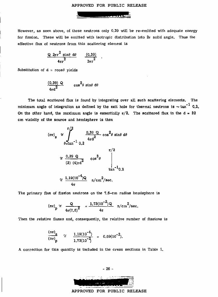
However, as seen above, of these neutrons only 0.39 will be re-emitted with adequate energy
for fission. These will be emitted with isotropic distribution into 27r solid angle. Thus the
effective flux of neutrons from this scattering element is
Q 2rr2 sin6 d8
4m2
Substitution of d = rcosll yields
(0.39) ,
2nr2
o(0.39) QII cos&8 sin8 dO
4rd”
The total scattered flux is found by integrating over all such scattering elements. The
minimum angle of integration as deftned by the exit hole for thermal neutrons is -J tan -1 0.2.
On the other hand, the maximum angle is essentially 7r/2, The scattered flux in the d = 32
cm vicinity of the source and hemisphere is then
(nv)5
The primary flux of
(nv)p
?r/2
J 0,39 Qg COS26 sin9 d64rd2
e=tan- 10.2
lr/2
~ 0.39 QCOS36
(3) (4)nd2
~ 1.19( 10-4)Q n,cm2,sec
4T
fission neutrons on the 7.6-cm radius hemisphere is
1.73(10-2) Q n,cm2/sec=4&=4= .
.
Then the relative fluxes and, consequently, the relative number of fissions is
~N 1.19(10-4)(nv)p = ‘= = 0.69(10-2).
.
A correction for this quantity is included in the cross sections in Table 1.
-26-
-----. . . . .J _
. ..— - .. ....
APPROVED FOR PUBLIC RELEASE
APPROVED FOR PUBLIC RELEASE

——- .-— .—., —.— -----—. .-—-. . . . ——-—— .-. . ------ __.
APPENDLX IV
CORRECTION FOR FISSIONS CAUSED BY NEUTRONS SCATTERED
FROM HEMISPHERES
Consider first the neutrons scattered from the aluminum hemisphere on which the U3 08238
is painted. 238In Fig. IVa, (r2 - rl) is the U3 08 thickness, t is the thickness of U308 “seen”
by a neutron scattered at point P in the Al.
To simplify the calculations, we consider now an entire sphere so that, by symmetry, all
scattering from points on the spherical radius rl- Scan be regarded as occurring at P.
In the triangle (rl, r2, t) the law of cosines gives
2‘2
=r~+t2- 2r1t cos (7r - 0!),
or
(IV-1)
t J 2 2a+r2-r2= -rcosa+1 r. cos1 21” (IV-2)
The probability for fission bjj this scattered neutron is
(6.023) (1023) put Gf
238
238 2380where pu is the U density in U3 e
Consider now a sphere of radius ~
(IV-3)
and t is given by Eq. (IV-2).
and center at P. The number of neutrons per square
centimeter incident on this sphere is ~r~2, where Q is the total number of neutrons scattered
at P. Therefore, the total number of fissions induced by these neutrons and occurring per unit
area of this sphere is, by Eq. (IV-3),
(6.023) (1023) pu iif Q
( -r cosa +.22
cos ff+r -r ) (IV-4)(238) (4TrR2)
1 21”
The area of a circular element of the sphere about P is 27rR2 sin~ d~; for all points of this
element the value of t is constant. Therefore, the number of fissions which occur in a circular
element (the center of which is on the x axis) of a sphere with a diameter of R, center at P, is
(6.023)(1023) Q ~f pudN = (
22 22~r cos a + r cos a+r -r ) 27rR2 sinfl d~. (IV-5)
(238) (47rR2)1 1 21
I
-27-——.- —._ :=—— --——— .Z
.. —__. . . . . . -
-,. ___ . .._- ._
. . . . .::, -.–
APPROVED FOR PUBLIC RELEASE
APPROVED FOR PUBLIC RELEASE

. .. . . . .... . .—-- . .. .. . .----- -,... .. .. ,._.—— -- .. . . .. . ..—.-. ...— —.—
Y
x
z/
I?@. IVa Geometry of neutron scattering from uranium backing hemisphere.
-28-
.. ..- -. ----
.:.-.—.— ,.—-
APPROVED FOR PUBLIC RELEASE
APPROVED FOR PUBLIC RELEASE

.- —-”~_—. —-—— ,,—-- —-----------
Thus, the total number of fissions caused by neutrons scattered at P is given by
~=m(60023)(1023)Q~fPN. J (238) (2) Y-r cosa +
1fl.o
J2222r cosa+r -r
1 21 ) sin(3 d~, (IV-6)
where the limits of integration include the 47r solid angle about P.
To integrate this expression, we must relate a and & To do this we use the law of
sines and other trigonometric relations as follows:
In triangle (rl, R, rl- 8 ),
sin a ‘1-~.~ ‘—–
‘1
Thus,
sinfl=~ sin a,‘1-8
and
Also, from Eq. (IV-7’),
r. Cos o!
and
‘1 Cos ad~ =— _ d a,rl-8 cosfl
or
r COSPd a.
2r18 +82
(Iv-7)
(Iv-9)
-29-
-. .-———-.— —.. ..
APPROVED FOR PUBLIC RELEASE
APPROVED FOR PUBLIC RELEASE

Combining Eq. (IV-7’) and Eq.
r,
(IV-9), we get
sins cosa _._.
Substituting Eq. (IV-10) into Eq.
(&J
N=
?/
(6.023) (1023)
(2) (238)
=0
If we define
then
(IV-6), we find ‘
~ = (6.023) (1023) ‘1 Q ‘if%
(2) (238) 1-: ‘
[
22
1
1/2p== 2 ‘2-rl ‘
rCos a! +
r?N.K J
1sins cosa da
2 28+82Cos a -— —r .2.
-K
also, if we define
A2
and substitute Eq.
(Iv-lo)
B=O L 1 “1 J
fll?’r
/“*-‘1
22‘2 - ‘1~
2‘1
(IV-11)
(IV-12)
(IV-13)
(IV-13) into Eq. (IV-12), then I
-30-.. ..-._—
—--- “:.—-- - --- ““.-—
APPROVED FOR PUBLIC RELEASE
APPROVED FOR PUBLIC RELEASE

-.=-.-..= -.
This equation is the general expression for the number of fissions induced by neutrons scattered
at the depth 8 .
Since, for the mean scattering depth at 8 ? 0.01 in. , COS2 a never approaches zero and,
indeed, is very large compared to A2, we can expand the numerator of the first integral in
Eq. (IV- 14), thus
~ 1/2(cos2ci + A ) A2 A4 A6= Cosa + -— + ------ ---- (IV-15a)
2 Cosa 8 COS3Ci 16 COS5~9
which, when substituted into Eq. (IV-14), gives
Now we determine the limits of integration for a. Obviously, a = O both for B = O and ~ . r,
so we use the equations preceding .Eq. (IV-9), which give
da ‘1-8
Cos p~=—
‘1Cos o! “
KA22
o!=sin-
1cl.o
Setting this equal to zero, we find. that jil =% and a = sin -1 ‘isrl for maximum a. Next we
divide each of the integrals in Eq. (IV-15) into two integrals, one for the limits zero and-1 rl -8
sin _ -1 r~ -8, the other for the limits sin _ and m. The first term of Eq. (IV-15) is‘1
1 ‘1 -8rl
(Y=Osins da + KA2 P sina(-da)
(
2
)
28+ 82 1/2 2Cos a -— —
‘1 r:
‘1
J(—
)COS20! -%:< ‘/2’‘1 rl
. -1 ‘1 -8
which , when integrated is
-+ ‘n(2r1~’) -
a=sm‘1
(IV-15)
-31-
---—__— .--”-- -. .
~ ., —->—:—--- ---= —.-=-. z_—- 2L----=---‘--
APPROVED FOR PUBLIC RELEASE
APPROVED FOR PUBLIC RELEASE

The second term of
KA44
.-..— — .--. ..—-. —-------.. —-- .“’--— “. :—
Eq. (IV-15), similarly evaluated, is
‘l(rI -s)812r, -8 \ “
Substituting Eqs. (IV-16) and (IV-17) into (IV-15), we get
()KA2 2’1-8N=rln
KA4rl (S1-8)8 + 4~2r1-~) “
(
(IV-17)
(IV-18)
It can be shown by the following analysis that the second term in Eq. (IV-18) is very small
compared to the first term. The ratio of the two terms is
A2r1 (r, -8)
28(2r1- 8)ln(2r18-8) “
In this experiment, rl~ 3 in. , A2 S 2.5(10-6), and we consider the mean scattering distance
8 ‘X 0.010 in. For these values, the above ratio is much less than unity. Therefore, Eq.
(IV-18) reduces to
()KA2 2rl -8N ~~ In8“
(IV-19)
Equation (IV- 19) gives N, assuming that all scattering takes place on a sphere of radius
(rl -8 ). It can be shown that when distributed scattering centers are taken into account, the
value for N is not appreciably different from that given by Eq. (IV-19). Also, isotropic scat-
tering of fast neutrons from the aluminum hemisphere has been assumed in deriving Eq. (IV-19);
however, if the angular distribution of fast neutrons scattered from aluminum as measured by
Jurney (LA-1339) is used in these calculations rather than a simple isotropic scattering, the238
result for the number of fissions N in the U coating from scattered neutrons is calculated
to be -7 percent greater than that given by Eq. (IV-19).
It remains now to determine the value of N for the actual hemispherical geometry of this
experiment (Eq. (IV- 19) is valid for spherical geometry). This is done in the following way
(a) N is calculated, assuming that all actual scattering points on the hemisphere “see” the
actual hemisphere in the same geometry as the polar scattering point of the calculations “sees”
its hemisphere, (b) N is calculated, assuming that all actual scattering points “see” the actual
hemisphere just as an equatorial scattering point of the calculations “sees” a hemisphere, (c)
a compromise between the two extreme values thus obtained is reached by the reasonable
-32- -—.-—=
APPROVED FOR PUBLIC RELEASE
APPROVED FOR PUBLIC RELEASE

-: -,....- . _—.. .----
-
considerations described below to give the value of N we use. The result for calculation (a) I
is obtained by subtracting from the total-sphere value of N calculated from Eq. (IV-19) the-1 rl
value of N obtained by integrating Eq. (IV-15) from P = O to ~ = tan — . The result for
calculation (b) is obtained simply by dividing the total-sphere value of ‘A ~~om Eq. (IV-19) by two.
It is readily seen that the scattered neutrons which “see” the greatest thickness of U238
are those with P roughly ~/2. Because of this, a very large fraction of the fissions induced by238
scattered neutrons are in a very small area of the U deposit surrounding the scattering
point. A consideration, such as (a) above, which completely takes into account this sensitive
area surrounding the” scattering points is a more accurate representation of the actual situation
of scattering points over the entire hemisphere than is a consideration, such as (b) above, which
takes into account only half the area surrounding a point. Indeed, it appears that (b) would be
approximately correct only for a small band of aluminum around the equator that is within a
distance of about (10-1, or (10-2) centimeters from the
the result of calculation (a) is weighted with respect to
somewhat arbitrary ratio of 20:1.
The result of these calculations is
238edge of the U deposit. Therefore,
the result of calculation (b) in the
N % (0.023)NP
238where Np is the number of U fissions caused by primary (unscattered) fast neutrons.
To calculate the number of
hemispherical copper case, consider Fig. IVb. The integral equation for N can be set up in
a way similar to that described at the beginning of this Appendix for the case of the aluminum
backing hemisphere. The resulting equation, which corresponds to Eq.
case, is
r/2
N.K’
/1CY2.0
T
+
J@1=7T/2
(IV-20)
U238fissions caused by fast neutrons scattered from the
2Cos a 2 sina2 da2
1/2‘2
~
-7’J1
2()cos a - A’2
sins2
‘2
96’
(IV-14) in the previous
COS(Y2 da2(IV-21)
APPROVED FOR PUBLIC RELEASE
APPROVED FOR PUBLIC RELEASE

Y
Fig IVb Geometry of neutron scattering from outer hemispheres.
-34- ..-
APPROVED FOR PUBLIC RELEASE
APPROVED FOR PUBLIC RELEASE

where
28Al = COS2Q1 +—
82+
~‘2 ~
28 82A2 = COS2C22 +— i——
‘2 ‘2
2(6.023) (1023) Q Ufpu r2
KI =(2) (238)
‘2+8(N-22)
(N-23)
In Eq. (IV-21), the third and fourth integrals involve the passage of neutrons into the spherical,U238
shell under consideration. The first and second integrals involve the exit of neutrons from
this shell. Expanding, and carrying out the integrations as before, we obtain
~=K’ (A’)2 ~n2r2+S +K’(A’)42 8 4 1)
82-—- —
2‘2 r2
;+28 )( )
. (N-24)22
1+8T—
‘2 ‘2
Since again the second term is small compared to the first term, we have, for spherical geo- 1
metry, the result
(N-25) ~
Now to determine K’ (Eq. (IV-22)), Q, the source strength of the scattered neutrons, must ~be known and to find this we use the angular distribution of scattered neutrons from copper as
measured by Jurney (LA-1339). Since only back-scattered neutrons are effective only the
back-scattering cross section is used.
The value of N for hemispherical geometry is again obtained first for two simplified cases:
(a) assuming that all scattering takes place at the pole, (b) assuming that all scattering takes
place at the equator.-1 r2+8as
Results for case (a) are obtained by substituting a2 = tan
the lower limits of the first and second integrals in Eq. (N-25). This removes the‘2
contribution of the exit neutrons through the lower hemisphere. Results for case (b) are obtained,
as before, by dividing the total-sphere value of Eq. (IV-25) by two. The method by which the
I
-35- ...-
—. -.---
APPROVED FOR PUBLIC RELEASE
APPROVED FOR PUBLIC RELEASE

average is to be taken is not as clear here as in the case of the aluminum backing hemisphere.
However, from the dimensions of the two hemispheres and from their relation in space, some-
what arbitrary assignments of weight two to the polar value and unity weight to the equatorial
value seem reasonable.
The value thus obtained for N, the number of U238fissions caused by fast neutrons
scattered from the copper case, is given by
N = (0.0051)NP
(IV-26)
Analysis similar to the above can be made to determine the number of U238fissions
caused by fast neutrons scattered from the aluminum collecting hemisphere and the cadmium
shield. The results of these calculations are, respecti~ely, N = (0.002)NP and N = (0.019)NP“
I
-36-
. . . . ----- ----.. .... ... ----- -- -..._ ..-
APPROVED FOR PUBLIC RELEASE
APPROVED FOR PUBLIC RELEASE

—...—._._. :.-. . -. -——-..
APPENDIX V
ATTENUATION AND SCATTERING OF THERMAL NEUTRONS BETWEEN
MONITOR F(YIL AND DISC SOURCE
In this Appendtx we shall be concerned with the fact that some of the fissions induced in
the U235 disc source and monitor foil are caused by thermal neutrons which have been scattered
from the dural plate between the disc source and monitor foil.
We simplify the calculation of this effect by assuming that all scattering takes place in
a single surface midway between the faces of the dural plate (see Fig. Va).
The number of neutrons scattered from dA into da is given by
a cos $ dA da
47rRz
where
()ptNasq = (nv)th ~ Al”
In Eq. (V-2), (nv)th is the thermal neutron flux from the reactor.
as are the density, thickness, mass number, and scattering cross
Avogadro’s number is expressed as N.
The number of fissions induced
(-u(q:z?
(v-1)
(v-2)
The quantities p, t, A, and
section, respectively.
in da from these scattered neutrons is given by
(v-3)
where the subscript U refers to the U235
disc source. Now the number of fissions in area a
from the neutrons scattered in dA is
and the total number of fissions in area A induced by neutrons scattered in the entire area A is
-37-.. .. ..
-..-.—.
APPROVED FOR PUBLIC RELEASE
APPROVED FOR PUBLIC RELEASE

da
\r.
. +,4
‘––––
/
Fig. Va Geometry of neutron scattering in the U235
source plate.
-38- . .. . . . —.. .. . . . .. . ____. .
APPROVED FOR PUBLIC RELEASE
APPROVED FOR PUBLIC RELEASE

where we have used the relations:
R2 = b2 + <2+ r2-2rYcos(o -@) (V-6)
da=rdrd@
The total number of fissions in the disc source of area a caused by unscattered thermal
neutrons incident on it after passage through the aluminum is given by
(v-7)
so that the ratio of the number of fissions from scattered neutrons to the number of fissions
from direct neutrons can, using Eq. (V-2), be written
()
ptwg
‘u
– ‘ 4=: [:y:~~)u] ‘1
‘u
(V-8)
where
Now consider the monitor foil. It is of the same area and same position relative to
the dural plate as the disc source; therefore, the total number of fissions induced by neutrons
scattered in the dural plate is given by an expression similar to Eq. (V-5), i. e.,
()ptNafNm=~—
A m 1’
where I is deftned by Eq. (V-9) and the subscript m refers to the monitor foil. The total
nuxrmer of fissions in the monitor foil from direct neutrons is given by
Hpmuf
N: . (nv)th a ~ m ,
-39-
~-–”- ‘“ - ‘“
(v-lo)
(V-n)
APPROVED FOR PUBLIC RELEASE
APPROVED FOR PUBLIC RELEASE

. .. .
and the ratio of fissions caused by scattered neutrons to fissions caused by direct neutrons is:
()ptmsNm —I
AAl—_ .N’m - 4na
Now, the total number of fissions
‘TU = N:
or
(V-12)
in the disc source, obtained from Eq. (V-8), is
‘TU = NL (l+%).
(V-13)
(V-14)
where 8U is substituted for the second term in the bracket. Similarly, the total number of
fissions in the monitor foil, obtained from Eq. (V-12), is
‘Tm = “m
or
()ptNas
AAll1+
4~a 1
N ~m = N& ( )l+sm . .
(v-.l5)
(V-16)
Now, the ratio of the number of fissions in the disc source to the number of fissions in
the monitor foil, obtained from Eqs. (V-14) and (V-16), is
From Eqs. (V-7) and (V-n)
(nv)th a~= (7)U [l-(-L]
()plwf
(nv)th a ~ mN’m
-40-
(V-17)
..——
—--—
APPROVED FOR PUBLIC RELEASE
APPROVED FOR PUBLIC RELEASE

-—.—
or
‘b ‘u
[( )]
ptwt.— l-y t
N’m Mm Al(V-18)
where M afid Mu ~ are the uranium masses of the disc source and monitor foil, -respectively.
Substituting Eq. (V-18) into Eq. (V-17), we have
‘TU ‘u
[()
ptwt
‘Tm ‘~ 1-A Al
It remains now only to evaluate 8U and 8 ~,
l+SU
() l+sm “
or, in particular, to evaluate I. If in
(V-19)
Eq. (V-9), we carry out in a straightforward masner the integr~tions over r and 0. we obtain
Integration over 9 reduces Eq. (V-20) to
19
Jr (b2+r:)
+-J?’ 2-4r~~2+r~ +-b’ -Q’I= -’n -t? d~ In
I
(V-21)‘b’
.
-?.0
Now we note that for this experiment, b’ = 0.00098 in. 2, r’= 0.1914 in. 2, i.e. , b’<< r’o o“
Using this in Eq. (V-21), we find that the integral becomes:
10
J
I=27r ldJ?ln2
or 1=0
()I=nln2 1o’.(v-22)
Substituting iIq. (V-22) into the expressions for 8 u and 8 m, we obtain
,. (+)M ( 1n2 ) &
“ 4a[1-(?)Ad
(
-41- .. —-. —,. ...-. . . . .. . ..-— —
(V-23)
APPROVED FOR PUBLIC RELEASE
APPROVED FOR PUBLIC RELEASE

(V-24)
Evaluating 8U and am by substituting into Eqs. (V-22) and (V-23) the proper numbers for
this experilne.t, we obtain
8U = 0.781 (10-2)
1sm = 0.775 (10-2)
Similarly
[1-(9)A1] = 0-9’14-
(V-25)
I(V-26)
Substituting Eqs. (V-25) and (V-26) into Eq. (V-19), we obtain
‘TU ‘u— = (0.992) ~‘Tm m
This correction is taken into account in deter inining the cross sections given in Table 1.
I
I
I
-42-.—.—. ..-. —
—
_ ,__. .
APPROVED FOR PUBLIC RELEASE
APPROVED FOR PUBLIC RELEASE
..i .
APPENDIX VI
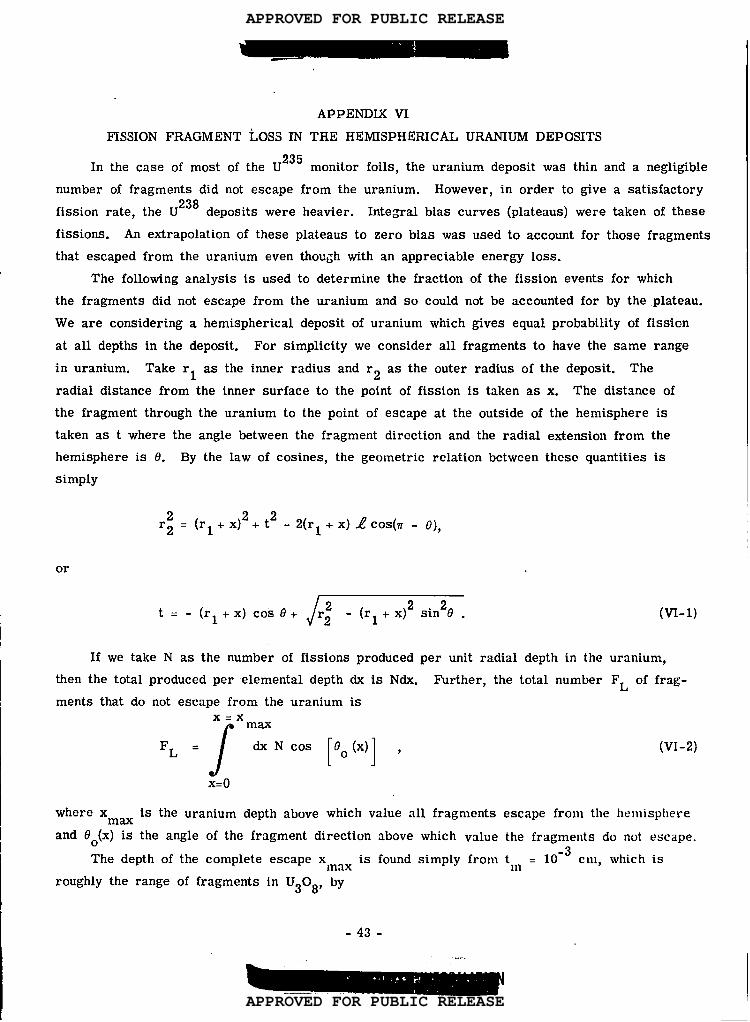
FISSION FRAGMENT LOSS IN THE HEMISPHERICAL URANIUM DEPOSITS
In the case of most of the U235
monitor foils, the uranium deposit was thin and a negligible
number of fragments did not escape from the uranium. However, in order to give a satisfactory
fission rate, the U238
deposits were heavier. Integral bias curves (plateaus) were taken of these
fissions. An extrapolation of these plateaus to zero bias was used to account for those fragments
that escaped from the uranium even thou~h with an appreciable energy loss.
The following analysis is used to determine the fraction of the fission events for which
the fragments did not escape from the uranium and so could not be accounted for by the,plateau.
We are considering a hemispherical deposit of uranium which gives equal probability of fissicn
at all depths in the deposit. For simplicity we consider all fragments to have the same range
in uranium. Take rl as the inner radius and r2 as the outer radius of the deposit. The
radial distance from the inner surface to the point of fission is taken as x. The distance of
the fragment through the uranium to the point of escape at the outside of the hemisphere is
taken as t where the angle between the fragment direction and the radial extension from the
hemisphere is 0. By the law of cosines, the geometric relation between these quantities is
simply
r; = (r1+x)2+t2 - 2(r1+x)Zcos(7r - 0),
or
Jt=-(rl+x) coke+ r; -(r1+x)2sin20. (w-l)
If we take N as the number of fissions produced per unit radial depth in the uranium,
then the total produced per elemental depth dx is Ndx. Further, the total number FL of frag-
ments that do not escape from the uranium isx.x
‘L=/ ‘:NcOs[’o(x)] ~x=o
(VI-2)
where x ma is the uranium depth above which value all fragments escape from the hemisphere
and 60(x) is the angle of the fragment direction
The depth of the complete escape Xlnax is
roughly the range of fragments in U308, by
-43
above which value the fragments do not escape.
found simply from t,ll = 10-3
cm, which is
.-
APPROVED FOR PUBLIC RELEASE
APPROVED FOR PUBLIC RELEASE

.. .------
(rl+ Xm)2
2 + (10-3)2 = r2,
where r ~ = 7.65 cm and r2 . rl + 10-5 -5
cm (here 10 is the total depth of the uranium de-
posit). From this we obtain the value Xm = 19.9( 10-6) cm. Similarly, the complete escape
angle 60 (x) applying to fissions from the partial escape depths is found from
r;=(rl + X)2+ t: [1+2(r1 +x) tm cos 90 (x) .
Substitution of the experimental values in Eq. (VI-3) gives
[1 (10-5 -5 -6Cos 00 (x) =
- x)(15.24 + 10 +x)-lo.
2( ’7.62 + X) (10-3)
(VI-3)
(VI-4)
The number of fissions lost FL is now found by substituting Eq. (VI-4) and Xm = 9.9 (10-6)
into Eq. (VI-2). For the -10-5238
cm thickness of U deposits used we obtain the value
FL = 4.9(10 -8)N. However,
bining these values, we find
uranium deposit is FL/Ft .
given in Table 1.
the total number of fissions in this deposit is Ft . 10-5N. Com-
that the percentage of fissions that do not escape from the
0.7%. This value has been used in calculating the final results
-44-— —— ——... —..—_ -. ----. ..- ...—,,. . .—
APPROVED FOR PUBLIC RELEASE
APPROVED FOR PUBLIC RELEASE

REPORT LIBRARY
REC. 17:;(31’.I.. . ..L. .....%
DATE . ...JL=.AS..A.!L
RECEIPT .-L ~
APPROVED FOR PUBLIC RELEASE
APPROVED FOR PUBLIC RELEASE