15. rc circuits · 15. rc circuits / structured 4 pasco / ps-3815 collect data 12. repeat the part...
TRANSCRIPT

NAME PERIOD DATE
PASCO / PS-3815 1
15. RC CIRCUITS STRUCTURED
Driving Question | Objective How do the potential differences across the resistors and capacitor in a simple RC circuit differ when the capacitor is charging, discharging, and fully charged, and how do these differences affect the current through each component in the circuit? Build a circuit like the one shown below, and use it to answer this driving question and to understand the behavior of the potential differences and currents in an RC circuit.
Materials and Equipment • Data collection system • Resistor3, 33-Ω • PASCO Wireless Voltage Sensor1 • Resistor3, 100-Ω • PASCO Wireless Current Sensor2 • Capacitor3, 470-μF • 4-mm banana plug patch cord with • Wire lead3 (6)
alligator clip1, 2 (4) • Battery (2), D-cell • PASCO AC/DC Electronics Laboratory3
1www.pasco.com/ap41 2www.pasco.com/ap42 3www.pasco.com/ap04
PASCO Wireless Voltage Sensor
PASCO Wireless Current Sensor
PASCO AC/DC Electronics Laboratory
Background Resistors and capacitors are two basic components used to control the potential differences and currents in a circuit. When a voltage source is applied to a simple circuit containing a capacitor, current flows in the circuit and the capacitor begins to charge. The rate at which the capacitor charges and the time it takes the capacitor to fully charge, are dependent on the size of the resistors and capacitor in the circuit and how they are connected. As the capacitor charges, the potential differences and currents within the circuit change over time. When the capacitor is fully charged, the circuit is in a steady-state condition where the potential difference and current are no longer changing. When the voltage source is removed, the circuit once again experiences changes in potential difference and current as the capacitor discharges. In this lab activity, you will wire a circuit containing two resistors, a capacitor, a battery, and a switch. The circuit positions one resistor in series with the capacitor and one in parallel with the capacitor. You will observe the changes in the potential difference and current for each component as the capacitor charges and discharges, and use your observations to answer questions about the magnitude and directions of the potential differences and currents in the circuit.
15. RC CIRCUITS / STRUCTURED
2 PASCO / PS-3815
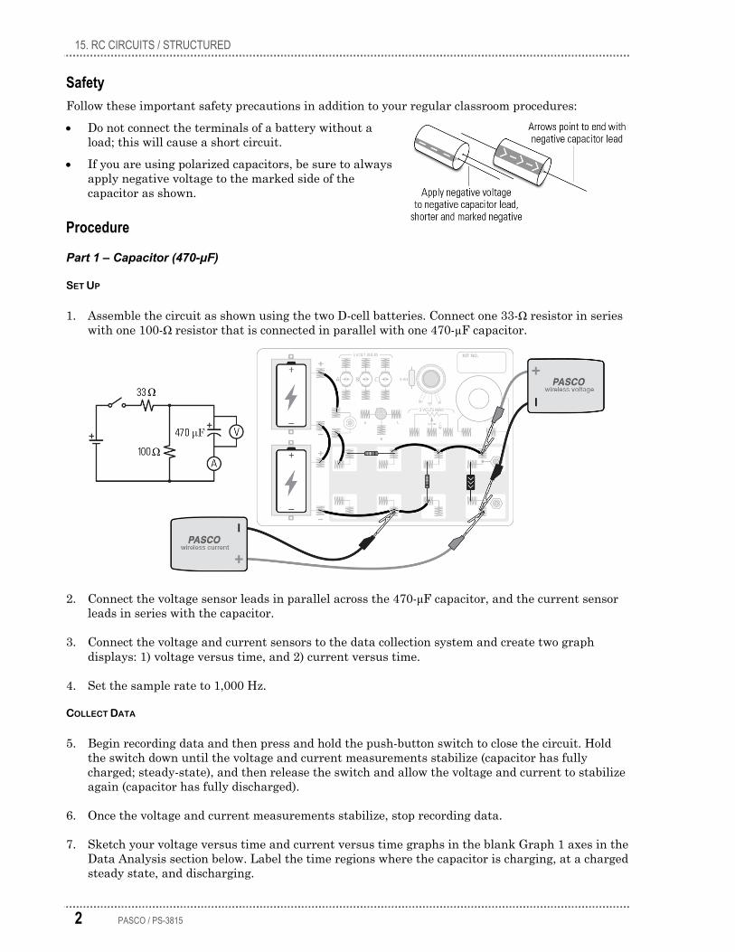
Safety Follow these important safety precautions in addition to your regular classroom procedures: • Do not connect the terminals of a battery without a
load; this will cause a short circuit. • If you are using polarized capacitors, be sure to always
apply negative voltage to the marked side of the capacitor as shown.
Procedure
Part 1 – Capacitor (470-μF)
SET UP
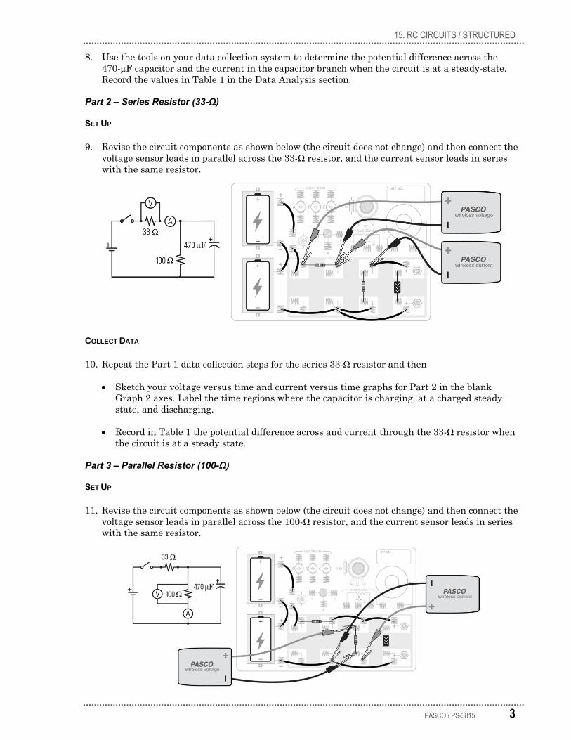
1. Assemble the circuit as shown using the two D-cell batteries. Connect one 33-Ω resistor in series with one 100-Ω resistor that is connected in parallel with one 470-µF capacitor.
2. Connect the voltage sensor leads in parallel across the 470-μF capacitor, and the current sensor leads in series with the capacitor.
3. Connect the voltage and current sensors to the data collection system and create two graph displays: 1) voltage versus time, and 2) current versus time.
4. Set the sample rate to 1,000 Hz.
COLLECT DATA
5. Begin recording data and then press and hold the push-button switch to close the circuit. Hold the switch down until the voltage and current measurements stabilize (capacitor has fully charged; steady-state), and then release the switch and allow the voltage and current to stabilize again (capacitor has fully discharged).
6. Once the voltage and current measurements stabilize, stop recording data.
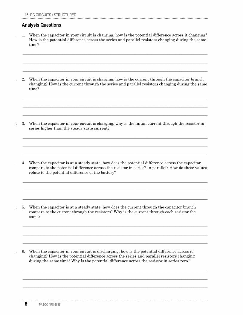
7. Sketch your voltage versus time and current versus time graphs in the blank Graph 1 axes in the Data Analysis section below. Label the time regions where the capacitor is charging, at a charged steady state, and discharging.
15. RC CIRCUITS / STRUCTURED
PASCO / PS-3815 3
8. Use the tools on your data collection system to determine the potential difference across the 470-µF capacitor and the current in the capacitor branch when the circuit is at a steady-state. Record the values in Table 1 in the Data Analysis section.
Part 2 – Series Resistor (33-Ω)
SET UP
9. Revise the circuit components as shown below (the circuit does not change) and then connect the voltage sensor leads in parallel across the 33-Ω resistor, and the current sensor leads in series with the same resistor.
COLLECT DATA
10. Repeat the Part 1 data collection steps for the series 33-Ω resistor and then
• Sketch your voltage versus time and current versus time graphs for Part 2 in the blank Graph 2 axes. Label the time regions where the capacitor is charging, at a charged steady state, and discharging.
• Record in Table 1 the potential difference across and current through the 33-Ω resistor when the circuit is at a steady state.
Part 3 – Parallel Resistor (100-Ω)
SET UP
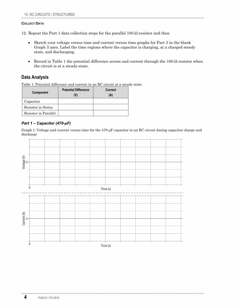
11. Revise the circuit components as shown below (the circuit does not change) and then connect the voltage sensor leads in parallel across the 100-Ω resistor, and the current sensor leads in series with the same resistor.
15. RC CIRCUITS / STRUCTURED
4 PASCO / PS-3815
COLLECT DATA
12. Repeat the Part 1 data collection steps for the parallel 100-Ω resistor and then
• Sketch your voltage versus time and current versus time graphs for Part 3 in the blank Graph 3 axes. Label the time regions where the capacitor is charging, at a charged steady state, and discharging.
• Record in Table 1 the potential difference across and current through the 100-Ω resistor when the circuit is at a steady-state.
Data Analysis Table 1: Potential difference and current in an RC circuit at a steady state
Component Potential Difference
(V) Current
(A)
Capacitor Resistor in Series Resistor in Parallel
Part 1 – Capacitor (470-μF) Graph 1: Voltage and current versus time for the 470-μF capacitor in an RC circuit during capacitor charge and discharge

15. RC CIRCUITS / STRUCTURED
PASCO / PS-3815 5
Part 2 – Series Resistor (33-Ω) Graph 2: Voltage and current versus time for 33-Ω series resistor in an RC circuit during capacitor charge and discharge
Part 3 – Parallel Resistor (100-Ω) Graph 3: Voltage and current versus time for 100-Ω parallel resistor in an RC circuit during capacitor charge and discharge
15. RC CIRCUITS / STRUCTURED
6 PASCO / PS-3815
Analysis Questions
1. When the capacitor in your circuit is charging, how is the potential difference across it changing? How is the potential difference across the series and parallel resistors changing during the same time?
_____________________________________________________________________________________________
_____________________________________________________________________________________________
_____________________________________________________________________________________________
2. When the capacitor in your circuit is charging, how is the current through the capacitor branch changing? How is the current through the series and parallel resistors changing during the same time?
_____________________________________________________________________________________________
_____________________________________________________________________________________________
_____________________________________________________________________________________________
3. When the capacitor in your circuit is charging, why is the initial current through the resistor in series higher than the steady state current?
_____________________________________________________________________________________________
_____________________________________________________________________________________________
_____________________________________________________________________________________________
4. When the capacitor is at a steady state, how does the potential difference across the capacitor compare to the potential difference across the resistor in series? In parallel? How do these values relate to the potential difference of the battery?
_____________________________________________________________________________________________
_____________________________________________________________________________________________
_____________________________________________________________________________________________
5. When the capacitor is at a steady state, how does the current through the capacitor branch compare to the current through the resistors? Why is the current through each resistor the same?
_____________________________________________________________________________________________
_____________________________________________________________________________________________
_____________________________________________________________________________________________
6. When the capacitor in your circuit is discharging, how is the potential difference across it changing? How is the potential difference across the series and parallel resistors changing during the same time? Why is the potential difference across the resistor in series zero?
_____________________________________________________________________________________________
_____________________________________________________________________________________________
_____________________________________________________________________________________________
15. RC CIRCUITS / STRUCTURED
PASCO / PS-3815 7
7. When the capacitor in your circuit is discharging, how is the current through the capacitor branch changing? How is the current through the series and parallel resistors changing during the same time? Why is the current through the capacitor branch negative?
_____________________________________________________________________________________________
_____________________________________________________________________________________________
_____________________________________________________________________________________________
Synthesis Questions
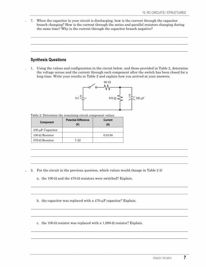
1. Using the values and configuration in the circuit below, and those provided in Table 2, determine the voltage across and the current through each component after the switch has been closed for a long time. Write your results in Table 2 and explain how you arrived at your answers.
Table 2: Determine the remaining circuit component values
Component Potential Difference
(V) Current
(A)
330-µF Capacitor 100-Ω Resistor 0.0158 470-Ω Resistor 7.42
_____________________________________________________________________________________________
_____________________________________________________________________________________________
_____________________________________________________________________________________________
2. For the circuit in the previous question, which values would change in Table 2 if:
a. the 100-Ω and the 470-Ω resistors were switched? Explain.
_____________________________________________________________________________________________
_____________________________________________________________________________________________
b. the capacitor was replaced with a 470-µF capacitor? Explain.
_____________________________________________________________________________________________
_____________________________________________________________________________________________
c. the 100-Ω resistor was replaced with a 1,000-Ω resistor? Explain.
_____________________________________________________________________________________________
_____________________________________________________________________________________________

15. RC CIRCUITS / STRUCTURED
8 PASCO / PS-3815
3. The following circuit contains a battery, two resistors, and a capacitor. A switch is placed in series with each resistor and a voltmeter is placed in parallel across resistor R1 and in parallel across the capacitor.
The following graphs represent four voltage measurements made by either voltmeter while switch S1 was momentarily closed then reopened.
Match the description below with its corresponding graph. Explain how you determined each match.
a. Voltage measured across resistor R1 while switch S2 remains open.
_____________________________________________________________________________________________
_____________________________________________________________________________________________
b. Voltage measured across resistor R1 while switch S2 remains closed.
_____________________________________________________________________________________________
_____________________________________________________________________________________________
c. Voltage measured across the capacitor while switch S2 remains open.
_____________________________________________________________________________________________
_____________________________________________________________________________________________
d. Voltage measured across the capacitor while switch S2 remains closed.
_____________________________________________________________________________________________
_____________________________________________________________________________________________