15 unitized power centers
TRANSCRIPT

CA08104001E For more information, visit:
www.eaton.com/consultants
September 2011
Contents
Unitized Power Centers 15.0-1
i
ii
1
2
3
4
5
6
7
8
9
10
11
12
13
14
15
16
17
18
19
20
21
Sheet
15
001
Un
itiz
ed
Po
wer
Ce
nte
rs
Unitized Power Centers
General Description and Application . . . . . . . . . . . . . . . . . . . . . . . . . . . . .
15.0-2
Ratings . . . . . . . . . . . . . . . . . . . . . . . . . . . . . . . . . . . . . . . . . . . . . . . . . . . . .
15.0-2
Advantages . . . . . . . . . . . . . . . . . . . . . . . . . . . . . . . . . . . . . . . . . . . . . . . . . .
15.0-2
Third-Party Listing . . . . . . . . . . . . . . . . . . . . . . . . . . . . . . . . . . . . . . . . . . . .
15.0-3
Seismic Qualification . . . . . . . . . . . . . . . . . . . . . . . . . . . . . . . . . . . . . . . . . .
15.0-3
Technical Data. . . . . . . . . . . . . . . . . . . . . . . . . . . . . . . . . . . . . . . . . . . . . . . .
15.0-4
Layout—Dimensions . . . . . . . . . . . . . . . . . . . . . . . . . . . . . . . . . . . . . . . . . .
15.0-5
Specifications
See Eaton’s
Product Specification Guide
, available on CD or on the Web.CSI Format: . . . . . . . . . . . . . . . . . . . . . . . . . . 1995 2010
Section 16313 Section 26 11 16.13
Unitized Power Center

15.0-2
For more information, visit:
www.eaton.com/consultants
CA08104001E
September 2011
Unitized Power Centers
i
ii
1
2
3
4
5
6
7
8
9
10
11
12
13
14
15
16
17
18
19
20
21
Sheet
15
General Description
002
Unitized Power Centers
Unitized Power Center
General Description and Application
Eaton’s unitized dry-type power centers are self-contained metal-enclosed unit substations especially designed to supply and distribute low voltage power from medium voltage lines in modern commercial and industrial systems. They are ideal where considerations of equipment size, accessibility, maintainability, ease of installation, and overall economy are uppermost.
Due to the inherent compactness of unitized power centers, they are easily and conveniently applied in multiples throughout a distribution system at physical locations close to centers of load concentration. The distribution voltage is thus stepped down to the utilization voltage only at or near the areas of demand with kVA being allocated as required for new construction or renovation in existing buildings. The application of unitized power centers in this manner results in several advantages not available with conventional secondary unit substations.
Ratings
■
Three-phase kVA:
❑
112.5–1000
■
Primary voltages:
❑
2.4 kV Class with 20 kV BIL, 60 Hz
❑
5 kV Class with 30 kV BIL, 60 Hz
❑
15 kV Class with 60 kV BIL, 60 Hz
❑
MV power system grounding—solid or low resistance grounded (
≥
100A) only. UPC product is not to be used on high-resistance or ungrounded MV power systems
■
Transformer windings:
❑
Primary connections—three-wire delta only
❑
Copper or aluminum
❑
Type AA, ventilated dry-type
❑
NEMA
®
Class 220°C insulation
❑
80, 115, 150°C rise. When transformer must meet require-ments of Federal 10CFR-431K, the 750 and 1000 kVA units are only available in 150°C rise
❑
Type FA (forced air) available, increases kVA ratings by 33%
❑
Primary taps at 95%, 97.5%, 100%, 102.5%, 105% of rated primary voltage
■
Secondary voltages:
❑
208Y/120V, four-wire
❑
240V, three-wire
❑
480Y/277V, four-wire
❑
480V, three-wire
❑
575/380V, four-wire
Advantages
■
Moving into place is facilitated by the rugged channel base construction and lifting eyes included with each assembly
■
All standard unitized power centers are especially designed to minimum dimensions consistent with safety and reliability
■
Standard unitized power centers are front-only accessible, making against-the-wall installations possible—minimum of 6.00 inches (152.4 mm) from wall for seismic applications, 2.00 inches (50.8 mm) for non-seismic
■
Future load growth is easily accom-modated by the addition of unitized power centers to the system without affecting the units serving the original load areas
■
Losses in the medium voltage portion of the distribution system are lower, resulting in a continuous operating savings
■
Secondary output voltage may be adjusted at each unitized power center to compensate for unusual load conditions without affecting the voltage setting of other appa-ratus in the system
■
Trouble is more quickly isolated with individual units located at or near their served loads
■
Primary power is purchased from the utility at the lower primary power rates, resulting in operational cost savings throughout the life of the equipment
■
Overall installed cost is lower because of the cost benefits of medium voltage distribution cable as compared to low voltage cable or busway
■
IQ Energy Sentinel™ devices can be provided on each feeder circuit to interface with an Eaton PowerNet™ system to monitor and display electrical energy (kWH). See
Tab 3
for more information
■
The IQ family of electronic meters can be provided to monitor the parameters unique to each type of device. With a PONI accessory, each of these devices can be connected to an Eaton PowerNet power monitoring system. See
Tab 2
for more information
CA08104001E For more information, visit:
www.eaton.com/consultants
15.0-3
September 2011
Unitized Power Centers
i
ii
1
2
3
4
5
6
7
8
9
10
11
12
13
14
15
16
17
18
19
20
21
Sheet
15
General Description—Technical Data
003
Advantages (continued)
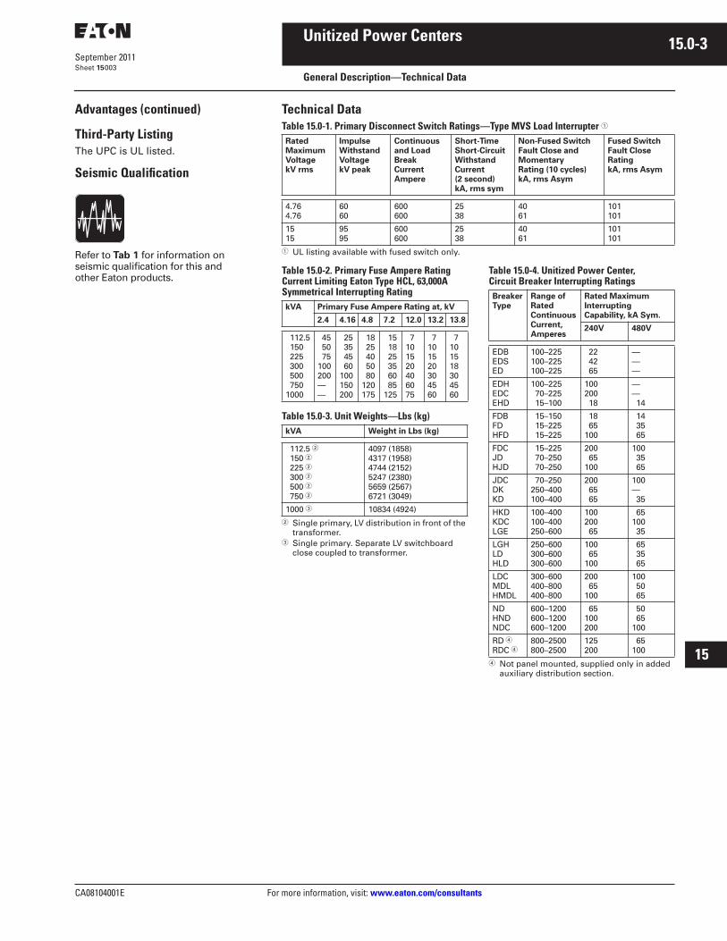
Third-Party Listing
The UPC is UL listed.
Seismic Qualification
Refer to
Tab 1
for information on seismic qualification for this and other Eaton products.
Technical Data
Table 15.0-1. Primary Disconnect Switch Ratings—Type MVS Load Interrupter
�
�
UL listing available with fused switch only.
Table 15.0-2. Primary Fuse Ampere Rating Current Limiting Eaton Type HCL, 63,000A Symmetrical Interrupting Rating
Table 15.0-3. Unit Weights—Lbs (kg)
�
Single primary, LV distribution in front of the transformer.
�
Single primary. Separate LV switchboard close coupled to transformer.
Table 15.0-4. Unitized Power Center, Circuit Breaker Interrupting Ratings
�
Not panel mounted, supplied only in added auxiliary distribution section.
Rated Maximum VoltagekV rms
Impulse Withstand VoltagekV peak
Continuous and Load Break Current Ampere
Short-Time Short-Circuit Withstand Current (2 second)kA, rms sym
Non-Fused SwitchFault Close and Momentary Rating (10 cycles)kA, rms Asym
Fused SwitchFault Close RatingkA, rms Asym
4.764.76
6060
600600
2538
4061
101101
1515
9595
600600
2538
4061
101101
kVA Primary Fuse Ampere Rating at, kV
2.4 4.16 4.8 7.2 12.0 13.2 13.8
112.5 150 225 300 500 7501000
45 50 75100200——
25 35 45 60100150200
18 25 40 50 80120175
15 18 25 35 60 85125
7101520406075
7101520304560
7101518304560
kVA Weight in Lbs (kg)
112.5
�
150
�
225
�
300
�
500
�
750
�
4097 (1858)4317 (1958)4744 (2152)5247 (2380)5659 (2567)6721 (3049)
1000
�
10834 (4924)
BreakerType
Range ofRatedContinuousCurrent,Amperes
Rated MaximumInterruptingCapability, kA Sym.
240V 480V
EDBEDSED
100–225100–225100–225
22 42 65
———
EDHEDCEHD
100–225 70–225 15–100
100200 18
—— 14
FDBFDHFD
15–150 15–225 15–225
18 65100
14 35 65
FDCJDHJD
15–225 70–250 70–250
200 65100
100 35 65
JDCDKKD
70–250250–400100–400
200 65 65
100— 35
HKDKDCLGE
100–400100–400250–600
100200 65
65100 35
LGHLDHLD
250–600300–600300–600
100 65100
65 35 65
LDCMDLHMDL
300–600400–800400–800
200 65100
100 50 65
NDHNDNDC
600–1200600–1200600–1200
65100200
50 65100
RD
�
RDC
�
800–2500800–2500
125200
65100

15.0-4
For more information, visit:
www.eaton.com/consultants
CA08104001E
September 2011
Unitized Power Centers
i
ii
1
2
3
4
5
6
7
8
9
10
11
12
13
14
15
16
17
18
19
20
21
Sheet
15
Technical Data
004
Table 15.0-5. Ventilated Dry-Type Transformer Standard Ratings
�
�
Refer to
Table 15.0-6
for available temperature rise, fan and secondary voltage options.
�
Short circuit currents assume unlimited utility source, and do not include motor contributions.
�
Maximum load/output is limited to 1200A due to chassis limitation.
�
Maximum load/output is limited to 3000A (cross bus limitation).
Note:
All units are three-phase, 60 Hz, 150°C rise, 220°C insulation system.
kVA Impedance%
kVClass
∆
PrimaryVolts
LIWV (BIL)
PrimaryTaps
WyeSecondaryVolts
Self-Cooled Fan Cooled (Optional) Transformer MaximumShort-Circuit Amperes rms Symmetrical
�
Secondary Full Load Amperes
kVA Secondary Full Load Amperes
208V 480V 208V 480V 208V 480V
112.5 150 225 300 500 7501000
4.54.54.54.54.55.55.5
5 2400,4160 or 4800
20 kV,30 kV,or 30 kV
±2–2-1/2% 208Y/120or480Y/277
312 416 625 833138920822776
135 180 271 361 601 9021203
150 200 300 400 66710001333
416 555 83311101200
�
27763000
�
180 241 361 481 80212031604
11566118961419415840241363620548274
5012 5155 6151 6561104591568920918
112.5 150 225 300 500 7501000
4.54.54.54.54.55.55.5
15 7200,1247013200 or 13800
30 kV,60 kV,60 kVor60 kV
±2–2-1/2% 208Y/120or480Y/277
312 416 625 833138920822776
135 180 271 361 601 9021203
150 200 300 400 66710001333
416 555 83311101200
�
27763000
�
180 241 361 481 80212031604
6245 83271249115140241363620548274
2706 3608 5413 6561104591568920918
CA08104001E For more information, visit:
www.eaton.com/consultants
15.0-5
September 2011
Unitized Power Centers
i
ii
1
2
3
4
5
6
7
8
9
10
11
12
13
14
15
16
17
18
19
20
21
Sheet
15
Layout—Dimensions
005
Unitized Power Centers—Available Configurations
■
MV switch will be fused or non-fused. UL listing available with fused switch only
■
MV fuse class: current limiting, Eaton Type HCL only
■
Primary surge protection shown is optional. Surge arresters, snubber pack or both can be provided
■
Use separate LV switchboard if:
❑
LV distribution chassis required is >1200A
❑
LV chassis-mounted devices will consume more than 36X of available chassis space
■
Bottom or top entry incoming high voltage cable size and quantity is limited to 250 kcmil, two per phase
■
Vent screens, filters, door gaskets or space heaters are not available in this product
■
FA rating (33% increase in kVA) is optional
■
Available transformer options—see
Table 15.0-6
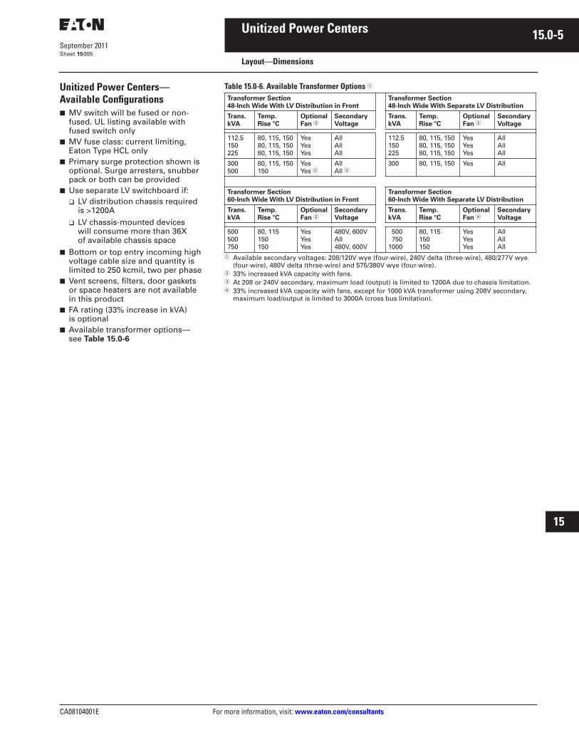
Table 15.0-6. Available Transformer Options
�
�
Available secondary voltages: 208/120V wye (four-wire), 240V delta (three-wire), 480/277V wye (four-wire), 480V delta (three-wire) and 575/380V wye (four-wire).
�
33% increased kVA capacity with fans.
�
At 208 or 240V secondary, maximum load (output) is limited to 1200A due to chassis limitation.
�
33% increased kVA capacity with fans, except for 1000 kVA transformer using 208V secondary, maximum load/output is limited to 3000A (cross bus limitation).
Transformer Section48-Inch Wide With LV Distribution in Front
Transformer Section48-Inch Wide With Separate LV Distribution
Trans.kVA
Temp.Rise °C
OptionalFan
�
SecondaryVoltage
Trans.kVA
Temp.Rise °C
OptionalFan
�
SecondaryVoltage
112.5150225
80, 115, 15080, 115, 15080, 115, 150
YesYesYes
AllAllAll
112.5150225
80, 115, 15080, 115, 15080, 115, 150
YesYesYes
AllAllAll
300500
80, 115, 150150
YesYes
�
AllAll
�
300 80, 115, 150 Yes All
Transformer Section60-Inch Wide With LV Distribution in Front
Transformer Section60-Inch Wide With Separate LV Distribution
Trans.kVA
Temp.Rise °C
OptionalFan
�
SecondaryVoltage
Trans.kVA
Temp.Rise °C
OptionalFan
�
SecondaryVoltage
500500750
80, 115150150
YesYesYes
480V, 600VAll480V, 600V
500 7501000
80, 115150150
YesYesYes
AllAllAll

15.0-6
For more information, visit:
www.eaton.com/consultants
CA08104001E
September 2011
Unitized Power Centers
i
ii
1
2
3
4
5
6
7
8
9
10
11
12
13
14
15
16
17
18
19
20
21
Sheet
15
Layout—Dimensions
006
Available Configurations
Figure 15.0-1. Single Primary, LV Distribution in Front of the Transformer
HV Left
100.00(2540.0)
HV Right
Top or Bottom Entry Top or Bottom Entry
Fan (optional)
Vent
85.00(2159.0)
80.00(2032.0)
2/phMax.
PowerTransformer
36.00(914.4)
48.00(1219.2)
60.00(1524.0)
or
One Line/Front Elevation One Line/Front Elevation
To L
V D
istr
ibu
tio
nC
has
sis
Fan (optional)
Vent
2/phMax.
PowerTransformer
To L
V D
istr
ibu
tio
nC
has
sis
PowerTransformer
PrimarySwitch
LV Distribution Chassis
PowerTransformer
PrimarySwitch
LV Distribution Chassis
FrontFoot Print
FrontFoot Print
36.64(930.7)
37.82(960.6)
Note: These UPCs are shipped fully assembled, except 5.00-inch (127.0 mm) top vent or 20.00-inch (508.0 mm) fan and vent assembly, which are shipped separately.

CA08104001E For more information, visit:
www.eaton.com/consultants
15.0-7
September 2011
Unitized Power Centers
i
ii
1
2
3
4
5
6
7
8
9
10
11
12
13
14
15
16
17
18
19
20
21
Sheet
15
Layout—Dimensions 007
Figure 15.0-2. Single Primary, Separate LV Distribution Switchboard Close-Coupled to Transformer
HV Left
100.00(2540.0)
HV Right
Top or Bottom Entry Top or Bottom Entry
Fan (optional)
Vent
90.00(2286.0)
85.00(2159.0)
80.00(2032.0)
2/phMax.
PowerTransformer
36.00(914.4)
48.00(1219.2)
60.00(1524.0)
or 36.00(914.4)
45.00(1143.0)
or
One Line/Front Elevation One Line/Front Elevation
To LV DistributionClose-CoupledSwitchboard
To LV DistributionClose-CoupledSwitchboard
Fan (optional)
Vent
2/phMax.
PowerTransformer
PowerTransformer
PrimarySwitch
PowerTransformer
PrimarySwitch LV Switchboard LV Switchboard
FrontFoot Print
FrontFoot Print
36.64(930.7)37.82
(960.6) 36.00(914.4)
= Shipping Split
Note: In addition to shipping splits shown, 5.00-inch (127.0 mm) top vent or 20.00-inch (508.0 mm) fan and vent assembly are also shipped separately.

15.0-8
For more information, visit: www.eaton.com/consultants CA08104001E
September 2011
Unitized Power Centers
i
ii
1
2
3
4
5
6
7
8
9
10
11
12
13
14
15
16
17
18
19
20
21
Sheet 15
Layout—Dimensions008
Figure 15.0-3. Duplex Primary, LV Distribution in Front of the Transformer
HV Left
100.00(2540.0)
HV Right
Top or Bottom Entry Top or Bottom Entry
Fan (optional)
Vent
85.00(2159.0)
80.00(2032.0)
2/phMax.
2/phMax.
PowerTransformer
36.00(914.4)
36.00(914.4)
48.00(1219.2)
60.00(1524.0)
or
One Line/Front Elevation One Line/Front Elevation
To L
V D
istr
ibu
tio
nC
has
sis
Fan (optional)
Vent
2/phMax.
2/phMax.
PowerTransformer
To L
V D
istr
ibu
tio
nC
has
sis
PowerTransformer
PrimarySwitch
PrimarySwitch
LV Distribution Chassis
PowerTransformer
PrimarySwitch
PrimarySwitch
LV Distribution Chassis
FrontFoot Print Front Foot Print
36.64(930.7)
37.82(960.6)
= Shipping Split
Note: In addition to shipping splits shown, 5.00-inch (127.0 mm) top vent or 20.00-inch (508.0 mm) fan and vent assembly are also shipped separately.

CA08104001E For more information, visit: www.eaton.com/consultants
15.0-9September 2011
Unitized Power Centers
i
ii
1
2
3
4
5
6
7
8
9
10
11
12
13
14
15
16
17
18
19
20
21
Sheet 15
Layout—Dimensions009
Figure 15.0-4. Duplex Primary, Separate LV Distribution Switchboard Close-Coupled to Transformer
100.00(2540.0)
Top or Bottom Entry
Fan (optional)Vent
90.00(2286.0)80.00
(2032.0)
2/phMax.
2/phMax.
PowerTransformer
36.00(914.4)
36.00(914.4)
48.00(1219.2)
60.00(1524.0)
or 36.00(914.4)
45.00(1143.0)
or
One Line/Front Elevation
To LV Distribution
Close-CoupledSwitchboard
PowerTransformer
PrimarySwitch
PrimarySwitch
LVSwitchboard
FrontFoot Print
36.00(914.4)
37.82(960.6)
= Shipping Split
85.00(2159.0)
36.64(930.7)
HV Right
Top or Bottom Entry
Fan (optional)Vent
2/phMax.
2/phMax.
PowerTransformer
One Line/Front Elevation
To LV Distribution
Close-CoupledSwitchboard
PowerTransformer
PrimarySwitch
PrimarySwitch
LVSwitchboard
FrontFoot Print
Note: In addition to shipping splits shown, 5.00-inch (127.0 mm) top vent or 20.00-inch (508.0 mm) fan and vent assembly are also shipped separately.

15.0-10
For more information, visit: www.eaton.com/consultants CA08104001E
September 2011
Unitized Power Centers
i
ii
1
2
3
4
5
6
7
8
9
10
11
12
13
14
15
16
17
18
19
20
21
Sheet 15
Layout—Dimensions010
Figure 15.0-5. Distribution Panel Layout Mounted in Front of Transformer up to 1200A Panel-Mounted Main and Feeder Devices � 100% rated main and feeder electronic trip breakers are available rated 400–1200A. 90°C wire rated at 75°C ampacity must be used.� May be used as a main device.Note: For main devices or main bus 1200A and below. Feeder devices mounted in front of transformer.Note: For auxiliary switchboard section layout—adjacent to transformer, refer to Figure 15.0-7 for switchboard section information.Note: Neutral conductor is always gutter mounted.
6X
4X
3X
2X
36X36X
Space forMain and Feeder
Molded CaseCircuit
Breakers�
TransformerVentilating Opening
2- or3-Pole
LD, LDB, HLD, LDC, MDL LGHMDL, ND, HND, NDC
� �
2-Pole 2-Pole
3-Pole 3-Pole ED, EDH,FD, FDB,FDC, HFD,JD, JDB,HJD, JDC �
DK, KD, KDB, HKD, KDC
2- or3-Pole
�
FD, FDB,
JD, JDB,HJD, JDC
ED, EDH,EDC, EHD,FD, FDB,
ED, EDH,EDC, EHD,FD, FDB,FDC, HFD
Molded Case Circuit Breaker—Layout �
See Table 15.0-2 for Ampere RatingsSecondary Distribution PanelboardMaximum Panel Height—“X” Unit

CA08104001E For more information, visit: www.eaton.com/consultants
15.0-11September 2011
Unitized Power Centers
i
ii
1
2
3
4
5
6
7
8
9
10
11
12
13
14
15
16
17
18
19
20
21
Sheet 15
Layout—Dimensions011
Figure 15.0-6. Base Plan View—HV Left, LV Distribution in Front of the Transformer
� Minimum recommended clearance on each side and rear = 2.00 inches (51.0 mm) for non-seismic applications, 6.00 inches (152.4 mm) for seismic applications. Local jurisdictions may require more.
� Minimum recommended clearance in the front = 36.00 inches (863.6 mm). Local jurisdictions may require more.
Note: Finished foundation surface shall be level within 0.06 inches (1.5 mm) in 36.00 inches (914.4 mm) left-to-right, front-to-back and diagonally, as measured by a laser level. Refer to actual order drawings for power cable conduit entrance locations.
Figure 15.0-7. Base Plan View—HV Left, LV Switchboard Close-coupled to Transformer on the Right
� Minimum recommended clearance on each side and rear = 2.00 inches (51.0 mm) for non-seismic applications, 6.00 inches (152.4 mm) for seismic applications. Local jurisdictions may require more.
� Minimum recommended clearance in the front = 36.00 inches (863.6 mm). Local jurisdictions may require more.
Note: Finished foundation surface shall be level within 0.06 inches (1.5 mm) in 36.00 inches (914.4 mm) left-to-right, front-to-back and diagonally, as measured by a laser level. Refer to actual order drawings for power cable conduit entrance locations.
PowerTransformer
PrimarySwitch
LV Distribution Chassis
Front
PowerTransformer
LVSwitchboard
PrimarySwitch
Front
3 3
4
3

15.0-12
For more information, visit: www.eaton.com/consultants CA08104001E
September 2011
Unitized Power Centers
i
ii
1
2
3
4
5
6
7
8
9
10
11
12
13
14
15
16
17
18
19
20
21
Sheet 15012
This page intentionally left blank.