150 & 172 series - aveo engineering … · 1.5 navigation lights installation – tail position...
TRANSCRIPT

Installation Instruction
150 & 172 SERIES
www.aveoengineering.com

CESSNA Installation Instructions
AVE-MOD-004-INS Issue 02
__________________________________________________________________________________
Aveo Engineering Group, s.r.o.
Drasov 202, 261 01 Drasov Czech Republic
Issue of form 01
Page 2 of 31
Part 0 Manual Administration
0.1 Table of Contents
PART 0 MANUAL ADMINISTRATION 2
0.1 TABLE OF CONTENTS 2
0.2 DOCUMENT APPROVAL 3
0.3 AMENDMENT RECORD PROCEDURE 3
0.4 EFFECTED PAGES PROCEDURE 3
0.5 DISTRIBUTION LIST 4
PART 1 INSTALLATION INSTRUCTION 5
1.1 GENERAL 5
1.2 DESCRIPTION 5
1.2.1 Position and anti-collision lights 5
1.2.2 Taxi- and landing lights 6
1.2.3 Energy consumtion 6
1.3 WINGTIP INSTALLATION CONVENTIONAL LIGHTS 8
1.3.1 Wingtip Installation Left 8
1.3.2 Wingtip Installation RIGHT 10
1.4 WINGTIP INSTALLATION CONFORMAL SOLUTION 12
1.4.1 Wingtip Installation LEFT 12
1.4.2 Wingtip Installation RIGHT 14
1.5 NAVIGATION LIGHTS INSTALLATION – TAIL POSITION 16
1.6 ANTICOLLISION LIGHT INSTALLATION 18
1.7 LANDING / TAXI LIGHT INSTALLATION 150 21
1.8 LANDING LIGHT INSTALLATION 150 23
1.9 LANDING / TAXI LIGHT INSTALLATION 172 25
1.10 ADDITION OF STROBE FUNCTION 28
PART 2 COMPLIANCE DEMONSTRATION 31

CESSNA Installation Instructions
AVE-MOD-004-INS Issue 02
__________________________________________________________________________________
Aveo Engineering Group, s.r.o.
Drasov 202, 261 01 Drasov Czech Republic
Issue of form 01
Page 3 of 31
0.2 Document approval
This document has been established in accordance with an alternative procedure to DOA approved under EASA AP429.
This installation Instruction is applicable for all Cessna 150 and 172.
Compiled by: 15 – Dec - 2017
Petr Jaros Engineer, Aveo Engineering Group, s.r.o.
Approved by: 15 – Dec - 2017
Georg Hartl Head of DO, Aveo Engineering Group, s.r.o.
0.3 Amendment Record procedure
The master copy of this document shall be kept electronically as a read only document under the control of Aveo Engineering Group, s.r.o. as Master Copy.
ALL amendments to this manual will initiate a raise of Issue ALL raises of issue will be given a sequential Alphabetic Issue Ident sequentially
from 01 to 99 in Table 01 - Issue No: Column– Initial Issue of Document will be
“01”
ALL Issues of this document will be approved by Head of DO
0.4 Effected Pages Procedure ALL pages affected by ANY raise of issue of this manual will be listed in Table 01 - Effected Pages Column. The reason(s) for ALL raise of issue and description of change due to raise of issue will be provided for ALL raises of issue in Table 01 - Details Column. Changes from the previous issue are highlighted by YELLOW HIGHLIGHTING over new content. AND YELLOW HIGHLIGHTING AND CROSSING OUT of deleted content.
Example (CROSSING OUT)
Issue No.
Details Date Effected Pages
01 Initial Issue 10 Nov
2016 ALL
02
Corrections as marked
addition of Conformal Solution §1.4
addition of two light anticollision light solution
15 Dec
2017
ALL
11-14
17-19
Table 01: Document Amendment Record Table

CESSNA Installation Instructions
AVE-MOD-004-INS Issue 02
__________________________________________________________________________________
Aveo Engineering Group, s.r.o.
Drasov 202, 261 01 Drasov Czech Republic
Issue of form 01
Page 4 of 31
0.5 Distribution List
As stated in 0.3 above; the master copy of this document shall be kept electronically as a read only document under the control of Aveo Engineering Group, s.r.o. as Master Copy.
All holders of copies of this Document will be recorded by listing in Table 02 –
Distribution List. Copy holders listed will be issued a copy of this document with sequential copy
number as shown in Table 02 – Distribution List
Copy No. Holder MASTER Aveo Engineering Group, s.r.o.
Table 02: Distribution List

CESSNA Installation Instructions
AVE-MOD-004-INS Issue 02
__________________________________________________________________________________
Aveo Engineering Group, s.r.o.
Drasov 202, 261 01 Drasov Czech Republic
Issue of form 01
Page 5 of 31
Part 1 Installation Instruction
1.1 General
This installation is to be performed in accordance to common practice as described in
FAR AC 43.13-2B Chapter 4 and in FAR AC 43.13 1B Chapter 11 Section 15 (Bonding) as published by FAA.
The installer is responsible to follow the installation instructions in the latest revision of:
FAR AC 43.13-2B Chapter 4
FAR AC 43.13 1B Chapter 11 Section 15
AVE-H30-001-IM AVE-WPS-64G-IM
AVE-POSW-54G-IM
AVE-RBXP-001-IM AVE-CCPS-IM_01
All drawings applicable for this change are listed in the Drawing List:
AVE-MOD-004-DL, issue 01
The following appliances carry an ETSO authorization:
AVE-POSW-54G – ETSOA 21O.10053449
AVE-WPSR-54G & AVE-WPSG-54G – ETSOA 21O.10053935
AVE-WPSR-64G & AVE-WPSG-64G – ETSOA 21O.10053936
AVE-RBXPR-001 – ETSOA 21O.10055069
AVE-RBXPR-002 – ETSOA 21O.10055069
AVE-CCPSR-63D & CCPSG-63D EASA Account Number: 307368
The change is to be performed using the document AVE-MOD-004-MCS in the latest issue.
The aircraft manuals remain fully valid. For maintenance of the new lights follow the Aveo Installation Manuals referenced above.
1.2 Description
This modification is the replacement of the composite wingtip segment and of
position, anti-collision, taxi- and landing lights by LED type lights.
1.2.1 Position and anti-collision lights The new position lights all also include the strobe function. Also two options for the
anti-collision lights can be installed. The RedBaron XP Galactica offers the red or white
anti-collision light or two units of RedBaron Mini Galactica. As not all C150 and 172 are already equipped with the strobe function (white strobe)

CESSNA Installation Instructions
AVE-MOD-004-INS Issue 02
__________________________________________________________________________________
Aveo Engineering Group, s.r.o.
Drasov 202, 261 01 Drasov Czech Republic
Issue of form 01
Page 6 of 31
in addition to the red beacon, this function may be added with this modification.
Hence the following optional installations can be done with this modification:
For aircraft with strobe function already installed:
Position lights including strobe + Beacon red (RedBaron XP)
Position lights including strobe + 2 Beacon red including strobe (RedBaron Mini)
For aircraft without strobe:
Position lights without strobe + Beacon red (RedBaron XP) Additional switch and wiring change + Position lights including strobe + Beacon
red (RedBaron XP or two RedBaron Mini)
Additional switch and wiring change + Position lights including strobe + Beacon red including strobe (RedBaron XP or two RedBaron Mini)
Synchronization: The strobe lights may be synchronized but the frequency of the strobes is so low that
synchronization of the lights is not required.
For the synchronization function the blue wires of each light to be synchronized have to be connected. If for this function additional wires are to be installed then these
must be installed along the wire bundle in which the lights power wires run. If the
function is not used the blue wire at each light is to be capped and stowed.
1.2.2 Taxi- and landing lights The C150 and 172 can be equipped with a taxi light (wide angle lens) and a landing
light (narrow angle). This modification allows replacing all installed taxi and landing lights with the same configuration as installed before the modification. A configuration
change is not allowed.
1.2.3 Energy consumtion The analysis (I= ∆IB a IL) showed that after installation of LED lights, in case of Position/Strobe lights , the total energy consumption dropped by 39.36% when Ultra
Galactica Embedded lights or by 31.06 % when Crystal Conforma lights were
installed.
In case of Landing/Taxi lights, the energy consumption dropped by 16.77 %. On the contrary, in case of Anti-collision lights, the energy consumption increased by 11.11%
when RedBaron XP Galactica or by 1.5 % when two RedBaron Mini Galactica lights
were installed. It was caused by higher power drain of our AVEO lights.

CESSNA Installation Instructions
AVE-MOD-004-INS Issue 02
__________________________________________________________________________________
Aveo Engineering Group, s.r.o.
Drasov 202, 261 01 Drasov Czech Republic
Issue of form 01
Page 7 of 31
Note:
GE4509, GE4626 original Cessna Langing and TAXI bulbs.
Lights Input Current
IBUBL (A) Lights
Input Current ILED (A)
Position light/strobe 2.0 / 1.7 Ultra Galactica 0.8 / 2.43
Position light/strobe 2.0 / 1.7 Ultra Galactica Embedded
0.56 / 2.1
Position light/strobe 2.0 / 1.7 Crystal Conforma 0.45 / 2.6
Tail position light 2.0 PosiStrobe CP 0.38 / 4.9
Anti-collision 4.0 RedBaron XP Galactica 4.5
Anti-collision 4.0 RedBaron Mini Galactica
2.03
GE4509 7.69 Hercules Drop-In Landing
6.4
GE4626 7.69 Hercules Drop-In Taxi 6.4
Table 03: Energy consumtion
CESSNA Installation Instructions
AVE-MOD-004-INS Issue 02
__________________________________________________________________________________
Aveo Engineering Group, s.r.o.
Drasov 202, 261 01 Drasov Czech Republic
Issue of form 01
Page 8 of 31
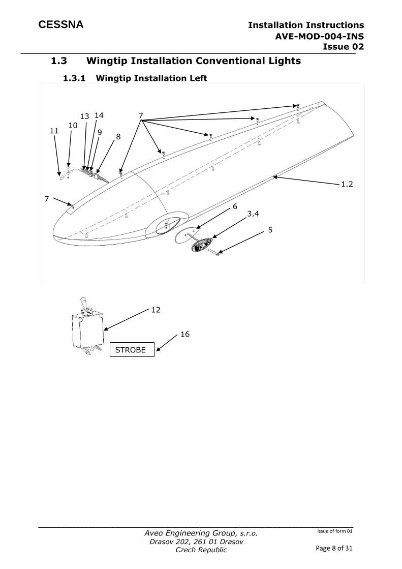
1.3 Wingtip Installation Conventional Lights
1.3.1 Wingtip Installation Left
12
STROBE
16
5
3,4
8
6
1,2
7
7
9
13
10 11
14

CESSNA Installation Instructions
AVE-MOD-004-INS Issue 02
__________________________________________________________________________________
Aveo Engineering Group, s.r.o.
Drasov 202, 261 01 Drasov Czech Republic
Issue of form 01
Page 9 of 31
Figure and Index Number
Part Number Description Parts Avail.
QTY. Per
assy.
1 2 3 4 5
6 7 8 9 10 11
-------
12 13 14 15 16
AVS-C220104050-A0A AVS-C120104060-A0A AVE-WPSTR-54G AVE-WPSR-64G AVS- P000102119-A30
AVS- P001290550-A1A
AN526C832R9 01-0430011-00 01-0410823-00 AN515-8R6 S1862-1 ----------------------
CM3589-10
Wingtip Fiberglass subassembly Left Wingtip Carbon subassembly Left Ultra Galactica (RED) Ultra Galactica embedded (RED) Screw M5x45
Gasket Original fasteners Connector Kit - Male Connector Kit - Female Screw Nutplate ------------------------------------------------
Breaker LDG Light AWG20 Wire – Yellow - Strobe AWG22 Wire – Blue - Synchro STROBE Sticker
-----
1 1 1 1 1
1 12 1 1 1 1
-----
1 1 1 1
NOTES
Remove installed wing tip and verify that aircraft structure is not subject to substantial
corrosion. In case of detected corrosion apply relevant AMM section or consult OEM
before continuing with this installation.
(#7) Use original fasteners to mount wingtips to the wing.
The lights are to be connected as described in manual AVE-WPS-54G-IM or AVE-WPS-
64G-IM. If the strobe function is not used the blue and the yellow wires described in
the component installation manual are not used and therefore have to be capped and stowed.
If the aircraft (Cessna 150 only) is not already equipped with the strobe function this
function can be installed through this change by following the instructions in §1.10. Additional cables for strobe (#13) and synchronization (#14) function and circuit
breaker (#12) and STROBE sticker (#16) are to be installed according to §1.10.
CESSNA Installation Instructions
AVE-MOD-004-INS Issue 02
__________________________________________________________________________________
Aveo Engineering Group, s.r.o.
Drasov 202, 261 01 Drasov Czech Republic
Issue of form 01
Page 10 of 31
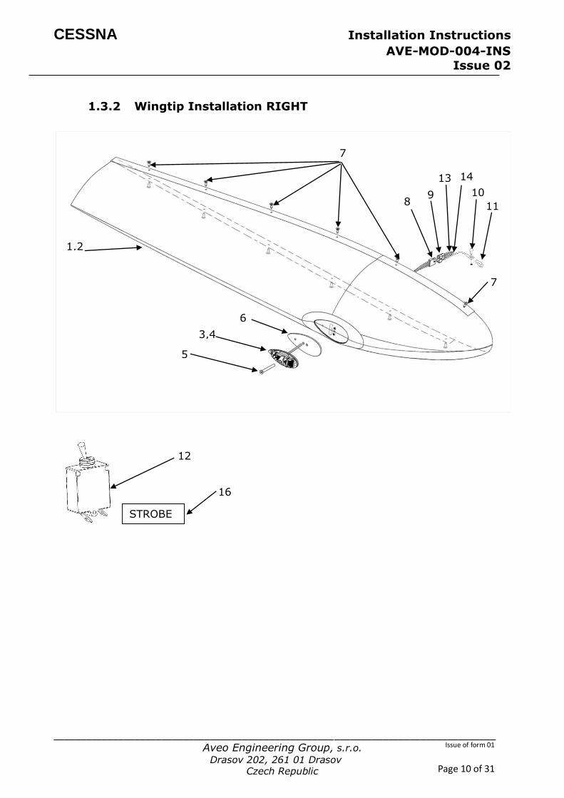
1.3.2 Wingtip Installation RIGHT
STROBE
16
1,2
5
3,4
6
8
7
7
9
13
10
11
14
12

CESSNA Installation Instructions
AVE-MOD-004-INS Issue 02
__________________________________________________________________________________
Aveo Engineering Group, s.r.o.
Drasov 202, 261 01 Drasov Czech Republic
Issue of form 01
Page 11 of 31
Figure and Index Number
Part Number Description Parts Avail.
QTY. Per
assy.
1 2 3
4 5 6 7 8 9 10 11
------- 12 13 14 15 16
AVS-C220104051-A0A AVS-C120104061-A0A AVE-WPSTG-54G
AVE-WPSG-64G AVS- P000102119-A30 AVS- P001290550-A1A
AN526C832R9 01-0430011-00 01-0410823-00 AN515-8R6
S1862-1 ---------------------- CM3589-10
Wingtip Fiberglass subassembly Right Wingtip Carbon subassembly Right Ultra Galactica (GREEN)
Ultra Galctica embeded (GREEN) Screw M5x45 Gasket Original fasteners Connector Kit - Male Connector Kit - Female Screw Nutplate ------------------------------------------------ Breaker LDG Light AWG20 Wire – Yellow - Strobe AWG22 Wire – Blue – Synchro STROBE Sticker
-----
1 1 1
1 1 1 12 1 1 1 1
----- 1 1 1
1
NOTES Remove installed wing tip and verify that aircraft structure is not subject to substantial
corrosion. In case of detected corrosion apply relevant AMM section or consult OEM
before continuing with this installation.
(#7) Use original fasteners to mount wingtips to the wing.
The lights are to be connected as described in manual AVE-WPS-54G-IM or AVE-WPS-64G-IM. If the strobe function is not used the blue and the yellow wires described in
the component installation manual are not used and therefore have to be capped and
stowed.
If the aircraft (Cessna 150 only) is not already equipped with the strobe function this
function can be installed through this change by following the instructions in §1.10. Additional cables for strobe (#14) and synchronization (#15) function and circuit
breaker (#13) and STROBE sticker (#16) are to be installed according to §1.10.

CESSNA Installation Instructions
AVE-MOD-004-INS Issue 02
__________________________________________________________________________________
Aveo Engineering Group, s.r.o.
Drasov 202, 261 01 Drasov Czech Republic
Issue of form 01
Page 12 of 31
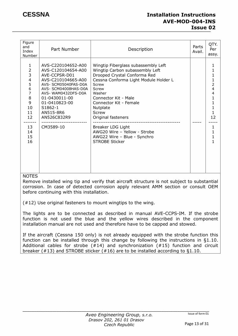
1.4 Wingtip Installation Conformal Solution
1.4.1 Wingtip Installation LEFT
13
7 4
1,2
6
STROBE
16
3 5
12
8 10
11
6 7
9
14 15
CESSNA Installation Instructions
AVE-MOD-004-INS Issue 02
__________________________________________________________________________________
Aveo Engineering Group, s.r.o.
Drasov 202, 261 01 Drasov Czech Republic
Issue of form 01
Page 13 of 31
Figure and Index Number
Part Number Description Parts Avail.
QTY. Per
assy.
1 2 3 4 5 6 7
8 9 10 11 12
------- 13 14 15 16
AVS-C220104652-A00 AVS-C120104654-A00 AVE-CCPSR-D01 AVS-C210104665-A00 AVS- SCM05040FAS-D0A AVS- SCM04008HAS-D0A AVS- WAM0432DFS-D0A
01-0430011-00 01-0410823-00 S1862-1 AN515-8R6 AN526C832R9
------------------------- CM3589-10
Wingtip Fiberglass subassembly Left Wingtip Carbon subassembly Left Drooped Crystal Conforma Red Cessna Conforma Light Module Holder L Screw Screw Washer
Connector Kit - Male Connector Kit - Female Nutplate Screw Original fasteners
------------------------------------------------ Breaker LDG Light AWG20 Wire – Yellow - Strobe AWG22 Wire – Blue - Synchro STROBE Sticker
-----
1 1 1 1 2 4 4
1 1 1 1 12
----- 1 1 1 1
NOTES
Remove installed wing tip and verify that aircraft structure is not subject to substantial corrosion. In case of detected corrosion apply relevant AMM section or consult OEM
before continuing with this installation.
(#12) Use original fasteners to mount wingtips to the wing.
The lights are to be connected as described in manual AVE-CCPS-IM. If the strobe
function is not used the blue and the yellow wires described in the component installation manual are not used and therefore have to be capped and stowed.
If the aircraft (Cessna 150 only) is not already equipped with the strobe function this function can be installed through this change by following the instructions in §1.10.
Additional cables for strobe (#14) and synchronization (#15) function and circuit
breaker (#13) and STROBE sticker (#16) are to be installed according to §1.10.
CESSNA Installation Instructions
AVE-MOD-004-INS Issue 02
__________________________________________________________________________________
Aveo Engineering Group, s.r.o.
Drasov 202, 261 01 Drasov Czech Republic
Issue of form 01
Page 14 of 31
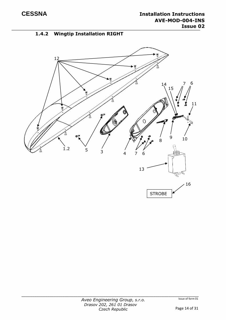
1.4.2 Wingtip Installation RIGHT
STROBE
16
1,2
12
5 3 4 7 6
13
8 9 10
15 7 6
11
14
CESSNA Installation Instructions
AVE-MOD-004-INS Issue 02
__________________________________________________________________________________
Aveo Engineering Group, s.r.o.
Drasov 202, 261 01 Drasov Czech Republic
Issue of form 01
Page 15 of 31
Figure and Index Number
Part Number Description Parts Avail.
QTY. Per
assy.
1 2 3 4 5 6 7 8 9 10 11 12
------- 13
14 15 16
AVS-C220104653-A00 AVS-C120104655-A00 AVE-CCPSG-D01 AVS-C210104664-A00 AVS- SCM05040FAS-D0A AVS- SCM04008HAS-D0A AVS- WAM0432DFS-D0A
01-0430011-00 01-0410823-00 S1862-1 AN515-8R6
AN526C832R9
------------------------- CM3589-10
Wingtip Fiberglass subassembly Right Wingtip Carbon subassembly Right Drooped Crystal Conforma - Green Cessna Conforma Light Module Holder R Screw Screw Washer Connector Kit - Male Connector Kit - Female Nutplate Screw Original fasteners ------------------------------------------------ Breaker LDG Light
AWG20 Wire – Yellow - Strobe AWG22 Wire – Blue - Synchro STROBE Sticker
-----
1 1 1 1 2 4 4 1 1 1 1 12
----- 1
1 1 1
NOTES
Remove installed wing tip and verify that aircraft structure is not subject to substantial
corrosion. In case of detected corrosion apply relevant AMM section or consult OEM before continuing with this installation.
(#12) Use original fasteners to mount wingtips to the wing.
The lights are to be connected as described in manual AVE-CCPS-IM. If the strobe
function is not used the blue and the yellow wires described in the component
installation manual are not used and therefore have to be capped and stowed.
If the aircraft (Cessna 150 only) is not already equipped with the strobe function this
function can be installed through this change by following the instructions in §1.10.
Additional cables for strobe (#14) and synchronization (#15) function and circuit breaker (#13) and STROBE sticker (#16) are to be installed according to §1.10.
CESSNA Installation Instructions
AVE-MOD-004-INS Issue 02
__________________________________________________________________________________
Aveo Engineering Group, s.r.o.
Drasov 202, 261 01 Drasov Czech Republic
Issue of form 01
Page 16 of 31
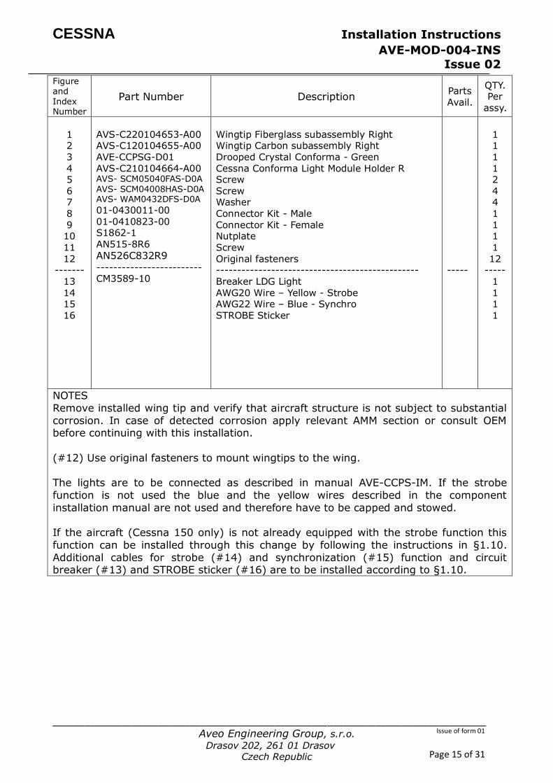
1.5 Navigation Lights Installation – Tail Position
1
2
3
4
6
7
5
8
9
10 11

CESSNA Installation Instructions
AVE-MOD-004-INS Issue 02
__________________________________________________________________________________
Aveo Engineering Group, s.r.o.
Drasov 202, 261 01 Drasov Czech Republic
Issue of form 01
Page 17 of 31
Figure and Index Number
Part Number Description Parts Avail.
QTY. Per
assy.
1 2 3 4 5 6 7 8 9
------- 10 11
921-204-00 AVE-POSW-54G S3231-5 MS35206-215 01-0430011-00 01-0410823-00 AN515-8R6 S1862-1 ----------------------
Mount PosiStrobe CP Rudder assembly Refer to 55-40-00 figure 01 Nut Screw Connector Kit - Male Connector Kit - Female Screw Nutplate ------------------------------------------------ AWG22 Wire – Blue – Synchro AWG20 Wire – Yellow - Strobe
-----
1 1 1 2 2 1 1 1 1
-----
NOTES
Remove installed navigation light and verify that aircraft structure is not subject to
substantial corrosion. In case of detected corrosion apply relevant AMM section or consult OEM before continuing with this installation.
The lights are to be connected as described in manual AVE-POSW-54G-IM. If the strobe function is not used the blue and the yellow wires described in the component
installation manual are not used and therefore have to be capped and stowed.
If the aircraft is not already equipped with the strobe function this function can be
installed through this change by following the instructions in §1.10. Additional cables
for strobe (#11) and synchronization (#10) function are to be installed according to
§1.10.

CESSNA Installation Instructions
AVE-MOD-004-INS Issue 02
__________________________________________________________________________________
Aveo Engineering Group, s.r.o.
Drasov 202, 261 01 Drasov Czech Republic
Issue of form 01
Page 18 of 31
1.6 Anti-collision Light Installation
A B
BOTTOM
B
TOP
9
STROBE 16
CESSNA Installation Instructions
AVE-MOD-004-INS Issue 02
__________________________________________________________________________________
Aveo Engineering Group, s.r.o.
Drasov 202, 261 01 Drasov Czech Republic
Issue of form 01
Page 19 of 31
Figure and Index Number
Part Number Description Parts Avail.
QTY. Per
assy.
1 2 3 4 5
6 7 8 9 10 11 12
13
-------- 14
-------- 1
2 3 4 5 6 7
8 9 10 11 12 13
--------
14 --------
1 2 3 4 5 6 7 8
-------- 14
--------
Option A AVS-P000102111-A3A AVE-RBXPR-001 AVE-LARBUHS-01B 0431017-2
NAS680A08 0431017-1 0431017-3 01-0430011-00 01-0410823-00 AN515-8R6 S1862-1 S1021Z6-4
MS35489-13 MS35489-4 ----------------------- ------------------------ Option B TOP AVS-P000100524-A3A
AVE- RBXPR-002 AVS-P000600111-A60 0431017-2 NAS680A08 0431017-1 0431017-3
01-0430011-00 01-0410823-00 AN515-8R6 S1862-1 S1021Z6-4 MS35489-13 MS35489-4 -------------------------
------------------------ Option B BOTTOM AVS-P000100524-A3A AVE- RBXPR-002 AVS-2LAM5033655Z-M00
MS20426AD3-8
01-0430011-00 01-0410823-00 AN515-8R6 S1862-1 ----------------------- ------------------------
Hex Socket Metric Screw Assy RedBaron XP Galactica Original Fasteners RedBaron Legacy Light Replacement Adapter Plate assembly mounting
Nutplate Tip Assembly- flashing beacon Tip Assembly- flashing beacon Connector Kit - Male Connector Kit - Female Screw Nutplate Screw
Gromet Gromet -------------------------------------------------- AWG22 Wire – Blue – Synchro -------------------------------------------------- Hex Socket Metric Screw Assy
RedBaron Mini Galactica Original Fasteners RedBaron Mini Light Replacement Adapter Plate assembly mounting Nutplate Tip Assembly- flashing beacon Tip Assembly- flashing beacon
Connector Kit - Male Connector Kit - Female Screw Nutplate Screw Gromet Gromet ------------------------------------------------
AWG22 Wire – Blue – Synchro ------------------------------------------------ Hex Socket Metric Screw Assy RedBaron Mini Galactica M5 Two Lug Anchor Nut Rivet Connector Kit - Male Connector Kit - Female Screw Nutplate -------------------------------------------------- AWG22 Wire – Blue – Synchro --------------------------------------------------
------ ------
------ ------ ------ ------
1 1 4 1 2
1 1 1 1 1 6 6 1
1 1
------ 1
------ 1
1 4 1 2 1 1 1
1 1 6 6 1 1 1
------ 1
------ 1 1 1 2 1 1 1 1 1
------ 1
------
CESSNA Installation Instructions
AVE-MOD-004-INS Issue 02
__________________________________________________________________________________
Aveo Engineering Group, s.r.o.
Drasov 202, 261 01 Drasov Czech Republic
Issue of form 01
Page 20 of 31
NOTES
Remove installed anticollision light and verify that aircraft structure is not subject to substantial corrosion. In case of detected corrosion apply relevant AMM section or
consult OEM before continuing with this installation.
The lights are to be connected as described in manuals AVE-RBXP-001-IM depending on which option is to be installed.
If the aircraft (Cessna 150 only) is not already equipped with the strobe function this function can be installed through this change by following the instructions in §1.10.
Option A: Additional cable for synchronization function (#14) is to be installed
according to §1.10.
Option B: Additional cable for synchronization function (#14) is to be installed
according to §1.10. Used drawing number 0104069 Fitting Modification for bottom light installation.
CESSNA Installation Instructions
AVE-MOD-004-INS Issue 02
__________________________________________________________________________________
Aveo Engineering Group, s.r.o.
Drasov 202, 261 01 Drasov Czech Republic
Issue of form 01
Page 21 of 31
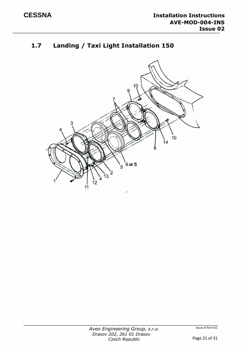
1.7 Landing / Taxi Light Installation 150
CESSNA Installation Instructions
AVE-MOD-004-INS Issue 02
__________________________________________________________________________________
Aveo Engineering Group, s.r.o.
Drasov 202, 261 01 Drasov Czech Republic
Issue of form 01
Page 22 of 31
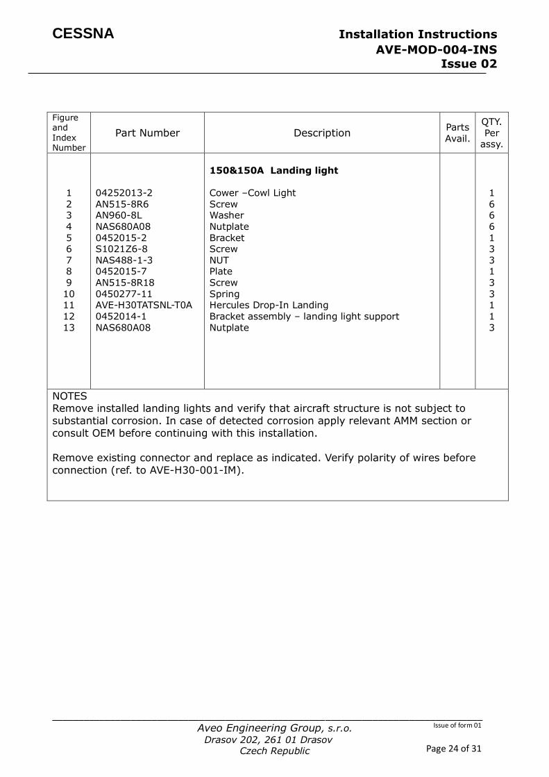
Figure and Index Number
Part Number Description Parts Avail.
QTY. Per
assy.
1 2 3 4 5 7 8 9 10 11 12 13
14 1 2 3
4 5 6 7 8 9 10 11 12 13 14
Option A 1752118-1 1752118-2 S1021Z6-8 AVE-H30TATSNL-T0A 0752646-1 1752118-3 1752118-4 AN515 8R6 NAS43DD3-12 AN960 -10 AN960-10L
NAS448-1-3 Option B 1752118-1 1752118-2
S1021Z6-8 AVE-H30TATSNL-T0A AVE-H30TATSNT-T0A 0752646-1 1752118-3 1752118-4 AN515 8R6 NAS43DD3-12 AN960 -10 AN960-10L NAS448-1-3
Support assembly – landing light Bracket LH Bracket RH Screw Hercules Drop-In Landing Gasket Plate assembly LH Plate assembly RH Screw Spacer -----LH only Washer-----LH only Washer-----LH only
NUT Support assembly – landing light Bracket LH Bracket RH
Screw Hercules Drop-In Landing Hercules Drop-In Taxi Gasket Plate assembly LH Plate assembly RH Screw Spacer -----LH only Washer-----LH only Washer-----LH only NUT
1 1 1 3 2
AR 1 1 3 1
AR AR
3 1 1 1
3 1 1
AR 1 1 3 1
AR AR 3
NOTES It is to be checked by the installer before the modification whether Option A or B is
installed on the aircraft. For a change in configuration e.g. 2 landing lights into 1
landing and 1 taxi light requires an additional EASA change.
Remove installed landing / taxi lights and verify that aircraft structure is not subject to
substantial corrosion. In case of detected corrosion apply relevant AMM section or
consult OEM before continuing with this installation.
Remove existing connector and replace as indicated. Verify polarity of wires before
connection (ref. to AVE-H30-001-IM).
CESSNA Installation Instructions
AVE-MOD-004-INS Issue 02
__________________________________________________________________________________
Aveo Engineering Group, s.r.o.
Drasov 202, 261 01 Drasov Czech Republic
Issue of form 01
Page 23 of 31
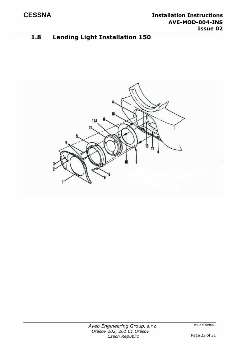
1.8 Landing Light Installation 150
CESSNA Installation Instructions
AVE-MOD-004-INS Issue 02
__________________________________________________________________________________
Aveo Engineering Group, s.r.o.
Drasov 202, 261 01 Drasov Czech Republic
Issue of form 01
Page 24 of 31
Figure and Index Number
Part Number Description Parts Avail.
QTY. Per
assy.
1
2 3 4 5 6 7 8
9 10 11 12 13
04252013-2
AN515-8R6 AN960-8L NAS680A08 0452015-2 S1021Z6-8 NAS488-1-3 0452015-7
AN515-8R18 0450277-11 AVE-H30TATSNL-T0A 0452014-1 NAS680A08
150&150A Landing light Cower –Cowl Light
Screw Washer Nutplate Bracket Screw NUT Plate
Screw Spring Hercules Drop-In Landing Bracket assembly – landing light support Nutplate
1
6 6 6 1 3 3 1
3 3 1 1 3
NOTES Remove installed landing lights and verify that aircraft structure is not subject to
substantial corrosion. In case of detected corrosion apply relevant AMM section or
consult OEM before continuing with this installation.
Remove existing connector and replace as indicated. Verify polarity of wires before
connection (ref. to AVE-H30-001-IM).

CESSNA Installation Instructions
AVE-MOD-004-INS Issue 02
__________________________________________________________________________________
Aveo Engineering Group, s.r.o.
Drasov 202, 261 01 Drasov Czech Republic
Issue of form 01
Page 25 of 31
1.9 Landing / Taxi Light Installation 172
Figure and Part Number Description
Parts
Avail.
QTY.
Per

CESSNA Installation Instructions
AVE-MOD-004-INS Issue 02
__________________________________________________________________________________
Aveo Engineering Group, s.r.o.
Drasov 202, 261 01 Drasov Czech Republic
Issue of form 01
Page 26 of 31
Index Number
assy.
1,2 3 4 5 6 7
8 9 10 11 12 13 14
15 16 17 18 19 20 21 22 23 24 25 26
1 2 3 4 5 6 7
8 9 10 11 12 13 14 15 16 17
18 19 20 21
22
AVE-H30TATSNL-T0A AN520 -10R18 S4216-1 1221059 NAS43DD3-36FC NAS43DD3-44FC
NAS1149F0363P NAS43dd3-24FC 0522116-1 NAS43DD3-48FC NAS1149F0363P
NAS42DD3-14FC S4216-1 1221059-6 AN520-10R18 1221059-5 S1021Z6-6 MS24693-S48 AN520-10R18 S1021Z6-8 NAS1149F0363P 0522113-2 C7358-014
AVE-H30TATSNT-T0A AVE-H30TATSNL-T0A AN520 -10R18 S4216-1 1221059 NAS43DD3-36FC NAS43DD3-44FC
NAS1149F0363P NAS43dd3-24FC 0522116-1 NAS43DD3-48FC NAS1149F0363P NAS42DD3-14FC S4216-1 1221059-6 AN520-10R18 1221059-5 S1021Z6-6 MS24693-S48
AN520-10R18
Option A
Hercules Drop-In Landing Screw Nut Plate Spacer Spacer
Washer Spacer Baffle assembly refer to 57-40-00figure 02 Finish Channel Spacer Bracket assembly refer to 57-40-00 figure 02 Washer
Spacer Nut Plate Screw Bracket Screw Screw Screw Screw Washer Lens assembly Ring alt C7358-014-27 Option B
Hercules Drop-In Taxi Hercules Drop-In Landing Screw Nut Plate Spacer Spacer
Washer Spacer Baffle assembly refer to 57-40-00figure 02 Finish Channel Spacer Bracket assembly refer to 57-40-00 figure 02 Washer Spacer Nut Plate Screw Bracket Screw Screw
Screw
2 6 4 1 2 1
AR 1 RF 1 1 RF AR
1 4 1 6 1 1 16 6 4
AR 01 NP
1 1 6 4 1 2 1
AR 1 RF 1 1 RF AR 1 4 1 6 1 1 16
6

CESSNA Installation Instructions
AVE-MOD-004-INS Issue 02
__________________________________________________________________________________
Aveo Engineering Group, s.r.o.
Drasov 202, 261 01 Drasov Czech Republic
Issue of form 01
Page 27 of 31
23 24 25 26
S1021Z6-8 NAS1149F0363P 0522113-2 C7358-014
Screw Washer Lens assembly Ring alt C7358-014-27
4 AR 01 NP
NOTES
It is to be checked by the installer before the modification whether Option A or B is installed on the aircraft. For a change in configuration e.g. 2 landing lights into 1
landing and 1 taxi light requires an additional EASA change.
Remove installed landing / taxi lights and verify that aircraft structure is not subject to substantial corrosion. In case of detected corrosion apply relevant AMM section or
consult OEM before continuing with this installation.
Remove existing connector and replace as indicated. Verify polarity of wires before
connection (ref. to AVE-H30-001-IM).

CESSNA Installation Instructions
AVE-MOD-004-INS Issue 02
__________________________________________________________________________________
Aveo Engineering Group, s.r.o.
Drasov 202, 261 01 Drasov Czech Republic
Issue of form 01
Page 28 of 31
1.10 Addition of strobe function
For aircraft C150 which are not already equipped with the strobe function this function
can be integrated using the following modification instruction.
Wiring Diagram
Option A
Option B

CESSNA Installation Instructions
AVE-MOD-004-INS Issue 02
__________________________________________________________________________________
Aveo Engineering Group, s.r.o.
Drasov 202, 261 01 Drasov Czech Republic
Issue of form 01
Page 29 of 31
Instrument panel C150 (actual instrument panel to be taken from AMM)
1
Use free location for
strobe switch – only is not
already equipped with the strobe function.
Label with STROBE
sticker
STROBE
2

CESSNA Installation Instructions
AVE-MOD-004-INS Issue 02
__________________________________________________________________________________
Aveo Engineering Group, s.r.o.
Drasov 202, 261 01 Drasov Czech Republic
Issue of form 01
Page 30 of 31
FIGURE AND INDEX
NUMBER PART NUMBER DESCRIPTION
PARTS AVAIL
QTY PER
ASSY
STROBE FUNCTION INSTALLATION
1 CM3589-10 Breaker LDG Light 1
2 STROBE Sticker 1
NOTES
To install the strobe light function (Cessna 150 only):
Install switches (item 1) into a free location off the instrument panel according
Aircraft Maintenance Manual. The switches are labeled “Strobe” and “Anti-collision”.
Wiring is to be performed according the wiring diagram. If the strobes are to be
synchronized then the blue wires of the position lights and the anti-collision light
must be connected. If the lights shall not be synchronized the blue wires of the different lights are to be capped and stowed.
The additional wires are to be installed along the wire bundle with the wires for the position and anti-collision lights.
CESSNA Installation Instructions
AVE-MOD-004-INS Issue 02
__________________________________________________________________________________
Aveo Engineering Group, s.r.o.
Drasov 202, 261 01 Drasov Czech Republic
Issue of form 01
Page 31 of 31
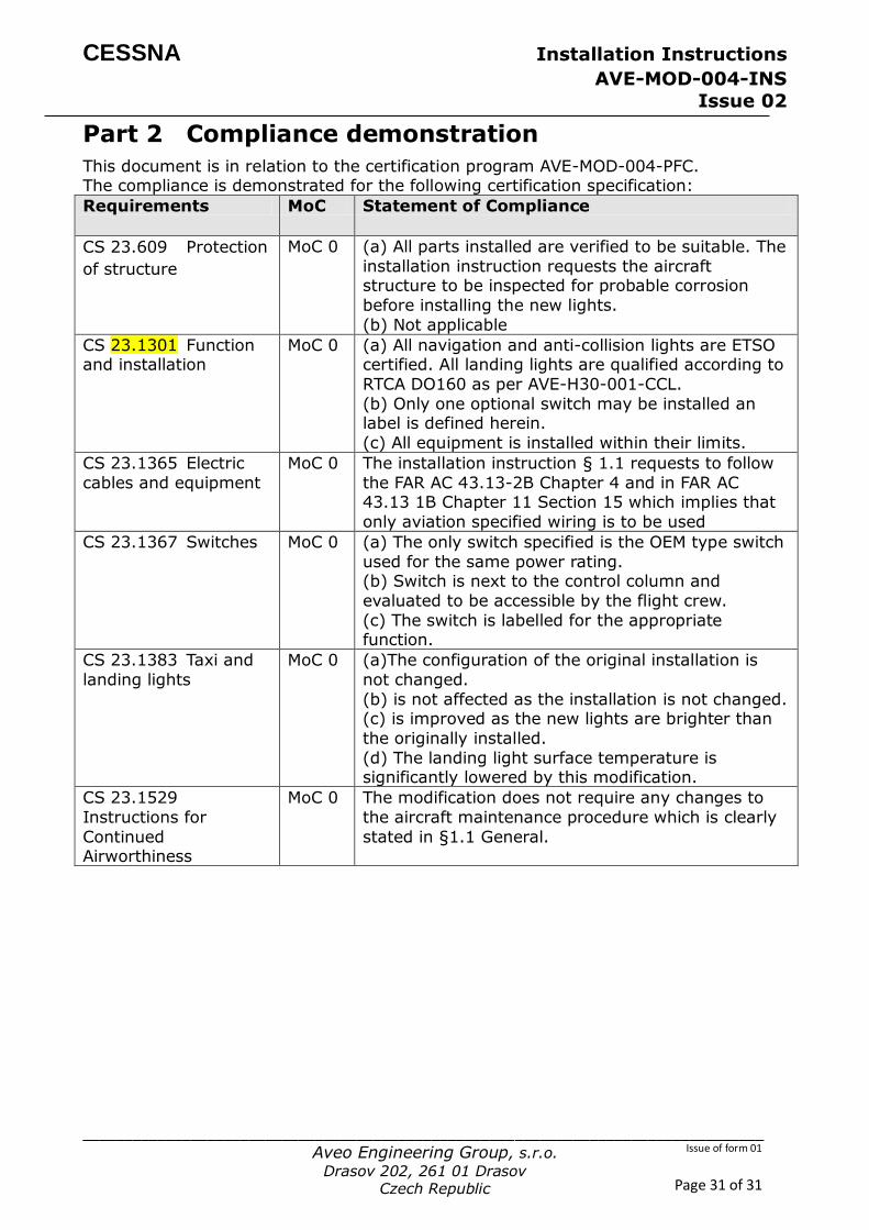
Part 2 Compliance demonstration
This document is in relation to the certification program AVE-MOD-004-PFC. The compliance is demonstrated for the following certification specification:
Requirements MoC Statement of Compliance
CS 23.609 Protection
of structure
MoC 0 (a) All parts installed are verified to be suitable. The
installation instruction requests the aircraft structure to be inspected for probable corrosion
before installing the new lights.
(b) Not applicable
CS 23.1301 Function and installation
MoC 0 (a) All navigation and anti-collision lights are ETSO certified. All landing lights are qualified according to
RTCA DO160 as per AVE-H30-001-CCL.
(b) Only one optional switch may be installed an label is defined herein.
(c) All equipment is installed within their limits.
CS 23.1365 Electric
cables and equipment
MoC 0 The installation instruction § 1.1 requests to follow
the FAR AC 43.13-2B Chapter 4 and in FAR AC 43.13 1B Chapter 11 Section 15 which implies that
only aviation specified wiring is to be used
CS 23.1367 Switches MoC 0 (a) The only switch specified is the OEM type switch
used for the same power rating. (b) Switch is next to the control column and
evaluated to be accessible by the flight crew.
(c) The switch is labelled for the appropriate function.
CS 23.1383 Taxi and
landing lights
MoC 0 (a)The configuration of the original installation is
not changed.
(b) is not affected as the installation is not changed. (c) is improved as the new lights are brighter than
the originally installed.
(d) The landing light surface temperature is significantly lowered by this modification.
CS 23.1529
Instructions for
Continued Airworthiness
MoC 0 The modification does not require any changes to
the aircraft maintenance procedure which is clearly
stated in §1.1 General.