15.40 - autonomous on-orbit assembly
TRANSCRIPT

© GMV, 2019 Property of GMV
All rights reserved
IOA-GNC: AUTONOMOUS ON-ORBIT ASSEMBLY
13th ESA Workshop on Avionics, Data, Control and
Software Systems (ADCSS2019)
14/11/2019 Page 2IOA-GNC: AUTONOMOUS ON-ORBIT ASSEMBLY
IOA-GNC: OBJECTIVES AND INNOVATIONPROJECT INTRODUCTION
Background:
Mastering autonomous in-orbit assembly technologies is crucial in order to enable future missions such as human exploration missions (requiring large in-orbit habitable structures) or scientific missions (requiring large reflectors).
High-level Objective:
IOA-GNC (Advanced GNC for In-Orbit Assembly of flexible vehicles) activity is devoted to the design, prototyping, verification and validation (till Model-in-The-Loop level) of an on-board control system aimed at controlling vehicle(s) of different in-orbit assembly scenarios.
Specific Lower-level Objectives, Challenges and Innovative Aspects/Paradigms:
Three realistic and challenging in-orbit assembly scenarios
Advanced multivariable GNC systems for autonomous in orbit assembly (applied to the three reference scenarios).
Robust control techniques (large MCI variations, growing structures and dynamic flexible systems, e.g. robotic manipulators)
Advanced FDA (Failure, Detection and Accommodation) techniques for sensors and thrusters.
Full goal-oriented (level E4) autonomy system for on-board re-planning in case of mission-level failures (nominal plan is no more achievable) with no ground intervention.

14/11/2019 Page 3IOA-GNC: AUTONOMOUS ON-ORBIT ASSEMBLY
TUG-BASED TELESCOPE ASSEMBLY (LTT)SCENARIOS OVERVIEW
Assembly of a telescope around a Central Module in a LLO, using a tug that retrieves reflectors from a safe orbit and transports them to the CM
Three elements in the rendezvous
– Tug
– Central Module
– Reflectors, in 6 stacks of 3 (18 total), in a non-drifting orbit of 2x1 km, 10 km behind the telescope with an out of plane component (safety)
Assembly operations description
– Tug separates from CM and transfers from CM orbit to reflector orbit.
– Tug deploys robotic arm and captures reflectors in the same manoeuvre, while the platform performs station keeping.
– Tug secures stack of reflectors and returns to CM, performing opposite set of manoeuvres.
– Tug deploys robotic arm and attaches to CM in the same manoeuvre, while the platform performs station keeping. Tug and CM are assembled into a “combo”.
– Combo assembles reflectors from storage point to structure through the CM robotic arm.
Autonomy level
– E3 (event-driven timeline) with major on-board re-planning capabilities at guidance/trajectory/manoeuvres level
STEP 1 – Rendezvous STEP 2 - Berthing
STEP 3 – Docking
STEP 4 –
Arm deployment
STEP 5 –
1st reflector transfer
STEP 6 –
1st reflector assembly
STEP 7 –
Next reflectors assembly
STEP 8 –
Next stacks assembly
STEP 1 – Stack Inspection
STEP 2 – Stack Capture
STEP 3 – Stack Storage STEP 4 – Arm available for rendezvous

14/11/2019 Page 4IOA-GNC: AUTONOMOUS ON-ORBIT ASSEMBLY
LUNAR SPACE STATION (LSS)SCENARIOS OVERVIEW
The assembly is performed by repeating a series of steps, changing the properties of the target (station, including angular momentum transfer during docking) and the chaser (Pressurized, Service and Combo modules).
The modules are separated in a point far from the station to avoid complex operations near the station, then are sent into a drifting trajectory.
One module approaches at a time on each assembly step.
The proposed assembly strategy favours a V-bar approach due to the passive safety added with this approach.
A total of 12 modules comprise the nominal station, using 4 stacks transported from LEO. In total, 7 assembly operations (steps).
Autonomy level
– E3 (event-driven timeline) with major on-board re-planning capabilities at guidance/trajectory/manoeuvres level
Stationrotation
Stationrotation
Stationrotation
Stationrotation
Stationrotation
Stationrotation

14/11/2019 Page 5IOA-GNC: AUTONOMOUS ON-ORBIT ASSEMBLY
SELF-SUFFICIENT TELESCOPE ASSEMBLY (HST)SCENARIOS OVERVIEW
Scenario:
– Assembly of a telescope around a Hub in a Halo orbit, using a swarm of reflectors that are assembled by means of a robotic arm
– Cargo vehicle transporting reflectors is already in a hold point in the same halo orbit 10 km away from the hub
– Six reflectors are released from the cargo with 0.3 m/s, in six different stable equally spaced directions.
– 3 cargos are considered for a total of 18 reflectors
Approaching trajectories designed as diagonal steps:
– Minimization of plume impingement
– Additional passive safety
Assembly operations description
– A single leg starts with a single reflector after commissioning.
– The reflector performs rendezvous operations and stays in the berthing box.
– Deployment of the robotic arm and capture of the reflector, by robotic arm motion.
Advanced FDA techniques included/validated in this scenario
Autonomy level:
– Full autonomy (level E4, goal-oriented) included/validated in this scenario

14/11/2019 Page 6IOA-GNC: AUTONOMOUS ON-ORBIT ASSEMBLY
GNC SUBMODESGNC MODES

14/11/2019 Page 7IOA-GNC: AUTONOMOUS ON-ORBIT ASSEMBLY
GUIDANCE DESIGN OVERVIEWGUIDANCE DESIGN
Guidance definition focused on intermediate to close rendezvous, including impulsive and forced motion trajectories
Low Lunar Orbit guidance based on LEO strategies for keplerian orbits
– State propagation performed using Yamanaka-Ankersen equations
– Main differences wrt LEO
• Longer reference orbital period (2 h vs 1.5 h)
• Smaller curvature radius (~1900 km ~6800 km)
• Different disturbances (gravity, drag…)
Halo guidance newly developed for this activity
– Halo dynamics are much slower than the typical LEO dynamics (14 days compared to 1.5 hours)
– Rendezvous strategies based on exploitation of orbital dynamics are unfeasible, as they require transfers that are of the order of magnitudes of the reference orbit -> a rendezvous would last months
– Approaching trajectories present very small curvatures over long periods of time. Manoeuvres can be considered straight lines for several hours development of “tacking strategy”
– Conclusions from IOA-GNC halo guidance design used as a starting point for NRO-GNC (HERACLES)

14/11/2019 Page 8IOA-GNC: AUTONOMOUS ON-ORBIT ASSEMBLY
GUIDANCE DESIGN
LLO MANOEUVRES
Impulsive guidance uses the following manoeuvres:
CTGM: cotangential transfer, analogous to Hohmann transfer, and used to transfer to higher / lower orbit
NDTM: non-drifting transfer, analogous to radial hop, and used to perform drift-free hops between hold points on V-bar
XING: manoeuvre at crossing point. Algorithm detects crossing between two trajectories and calculates manoeuvre required to pass from one trajectory to the next
YCTR: out-of-plane control. Adjusts out-of-plane manoeuvre at node.
TPTR: two-point transfer. Calculates two ∆V’s based on initial state, terminal state and transfer time
Guidance plan contains sequence of manoeuvres, plus parameters that define desired relative state
Relative state is propagated using the Yamanaka-Ankersenequations
z
x 1
2 3
4,5 6
1. CTGM2. XING3. CTGM4. XING5. NDTM6. XING

14/11/2019 Page 9IOA-GNC: AUTONOMOUS ON-ORBIT ASSEMBLY
GUIDANCE DESIGN
HALO IMPULSIVE MANOEUVRES
Approach in zig-zag: “Tacking”
– Straight line approach exploiting (lack of) halo dynamics
– Increased safety by not approaching target directly
– Improved navigation by approaching at an angle
– Allows to get relatively close to target without thrusting towards target, allowing reduced plume impingement
Safety considerations
– Trajectory defined as an angle with respect to target LOS
– Angle of approach defined assuming
• Large errors in radial direction due to navigation estimation
• Control errors in manoeuvre application
• Guidance error due to non-modelled dynamics
Guidance performs the following functions
– Calculate approach angle for next tack
– Calculate approach direction, taking Sun direction into consideration
– Calculate approach ∆V, based on estimated distance and transfer time
– Monitor current approach angle obtained from navigation and determine time of next manoeuvre
– Monitor current distance
Trajectory constraints
D
P1
P2
PB

14/11/2019 Page 10IOA-GNC: AUTONOMOUS ON-ORBIT ASSEMBLY
ON-BOARD AUTONOMY DESIGN
AUTONOMY SYSTEM OVERVIEW
Scenario:– Assembly of a telescope around a Hub in a Halo orbit
– Six reflectors are released from the cargo for docking with the central module.
Objectives of the Autonomy subsystem:
– Generate a new temporal plan for completing the docking of all operative reflectors after a fault (re-planning)
– Decide the sequence and parameters for assembling the reflectors to comply with resource (propellant and battery) restrictions
– Determine the desired transference time for each reflector (among N predefined transfer times)
– Model the battery and propellant consumption as linear functions
– Generate an optimal plan (wrt. time, time/propellant)
1
2
3
45
6
Reflectorr
Bat. Prop.
Central Module
r
#1
#5#4
#3
#2
14/11/2019 Page 11IOA-GNC: AUTONOMOUS ON-ORBIT ASSEMBLY
ON-BOARD AUTONOMY DESIGN
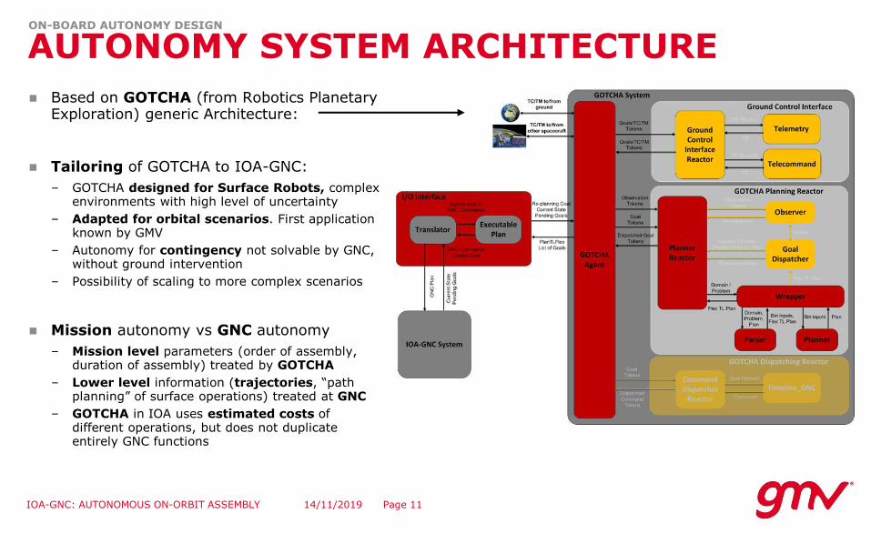
AUTONOMY SYSTEM ARCHITECTURE
Based on GOTCHA (from Robotics Planetary Exploration) generic Architecture:
Tailoring of GOTCHA to IOA-GNC:
– GOTCHA designed for Surface Robots, complexenvironments with high level of uncertainty
– Adapted for orbital scenarios. First applicationknown by GMV
– Autonomy for contingency not solvable by GNC, without ground intervention
– Possibility of scaling to more complex scenarios
Mission autonomy vs GNC autonomy
– Mission level parameters (order of assembly, duration of assembly) treated by GOTCHA
– Lower level information (trajectories, “pathplanning” of surface operations) treated at GNC
– GOTCHA in IOA uses estimated costs of different operations, but does not duplicateentirely GNC functions
14/11/2019 Page 12IOA-GNC: AUTONOMOUS ON-ORBIT ASSEMBLY
ON-BOARD AUTONOMY DESIGN
AUTONOMY SYSTEM OVERVIEW
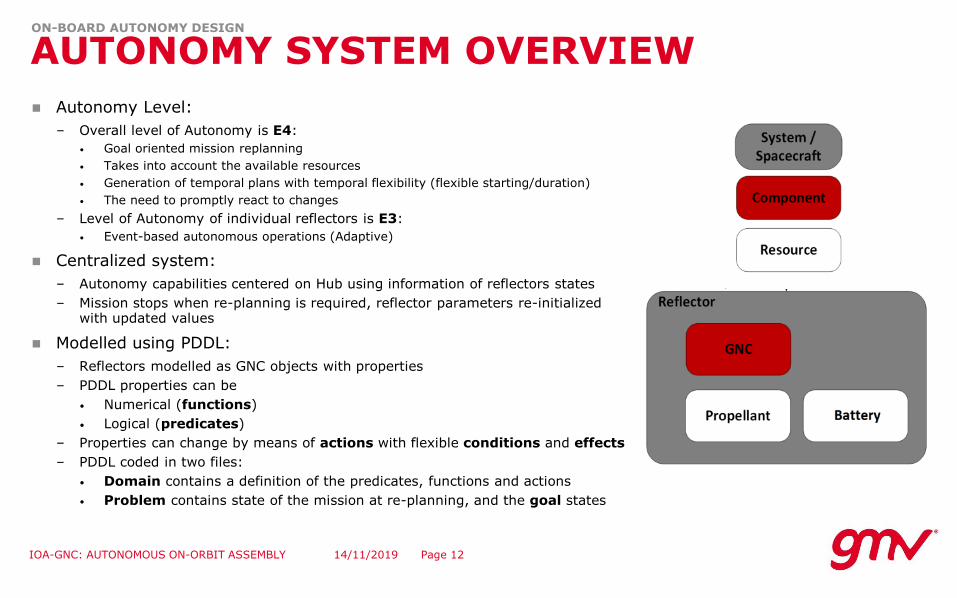
Autonomy Level:
– Overall level of Autonomy is E4:
• Goal oriented mission replanning
• Takes into account the available resources
• Generation of temporal plans with temporal flexibility (flexible starting/duration)
• The need to promptly react to changes
– Level of Autonomy of individual reflectors is E3:
• Event-based autonomous operations (Adaptive)
Centralized system:
– Autonomy capabilities centered on Hub using information of reflectors states
– Mission stops when re-planning is required, reflector parameters re-initialized with updated values
Modelled using PDDL:
– Reflectors modelled as GNC objects with properties
– PDDL properties can be
• Numerical (functions)
• Logical (predicates)
– Properties can change by means of actions with flexible conditions and effects
– PDDL coded in two files:
• Domain contains a definition of the predicates, functions and actions
• Problem contains state of the mission at re-planning, and the goal states
14/11/2019 Page 13IOA-GNC: AUTONOMOUS ON-ORBIT ASSEMBLY
ON-BOARD AUTONOMY DESIGN
AUTONOMY SYSTEM RESOURCES
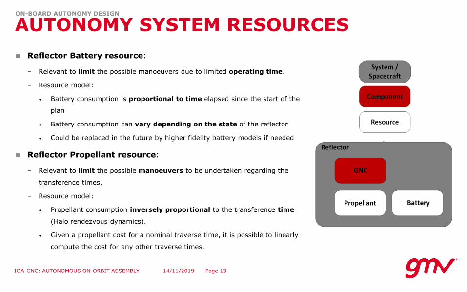
Reflector Battery resource:
– Relevant to limit the possible manoeuvers due to limited operating time.
– Resource model:
• Battery consumption is proportional to time elapsed since the start of the
plan
• Battery consumption can vary depending on the state of the reflector
• Could be replaced in the future by higher fidelity battery models if needed
Reflector Propellant resource:
– Relevant to limit the possible manoeuvers to be undertaken regarding the
transference times.
– Resource model:
• Propellant consumption inversely proportional to the transference time
(Halo rendezvous dynamics).
• Given a propellant cost for a nominal traverse time, it is possible to linearly
compute the cost for any other traverse times.
14/11/2019 Page 14IOA-GNC: AUTONOMOUS ON-ORBIT ASSEMBLY
ON-BOARD AUTONOMY DESIGN
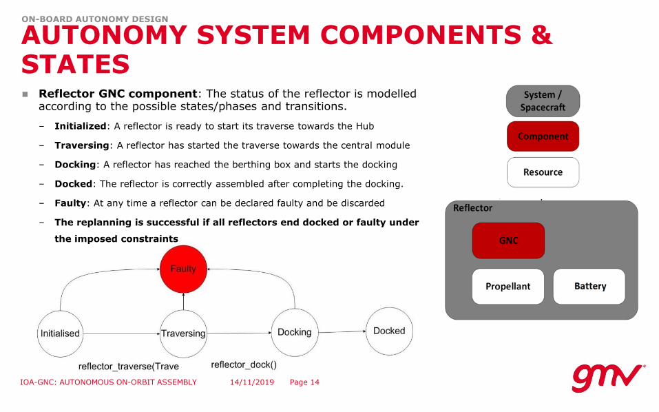
AUTONOMY SYSTEM COMPONENTS & STATES Reflector GNC component: The status of the reflector is modelled
according to the possible states/phases and transitions.
– Initialized: A reflector is ready to start its traverse towards the Hub
– Traversing: A reflector has started the traverse towards the central module
– Docking: A reflector has reached the berthing box and starts the docking
– Docked: The reflector is correctly assembled after completing the docking.
– Faulty: At any time a reflector can be declared faulty and be discarded
– The replanning is successful if all reflectors end docked or faulty under
the imposed constraints

14/11/2019 Page 15IOA-GNC: AUTONOMOUS ON-ORBIT ASSEMBLY
ON-BOARD AUTONOMY DESIGN
AUTONOMY SYSTEM ACTIONS
Traverse_reflector (traverse_time): execute the traverse phase
– Duration: The reflector traverse time (parameter): Nominal Traverse Time multiplied by one of the possible traverse time multipliers.
– Precondition: Enough battery to complete the Traversing and Docking phases.
– Precondition: Enough propellant to complete the traverse in the specified time.
– Effect: The reflector passes to Docking state.
Dock Reflector(): execute the docking phase for a reflector
– Duration: duration of the docking phase (fixed).
– Conditions: the reflector is in Docking state.
– Effects: The reflector passes to Docked state.

14/11/2019 Page 16IOA-GNC: AUTONOMOUS ON-ORBIT ASSEMBLY
ON-BOARD AUTONOMY DESIGN
AUTONOMY SYSTEM TEST CASES
Test cases
– Single failure: A single reflector is compromised during the assembly sequence. The fault can be detected in any reflector during the assembly of another reflector, of during the assembly of the faulty reflector itself. Twotest per failure modelled. Modelled cases are:
• Propellant depletion: Propellant level of one reflector not enough to complete whole assembly. Modelled as lower ΔV available
• Robotic Arm Grasping Point/Docking Site failure: Need to try a different assembly point or grapplingpoint. Modelled as increased duration of berthing/docking phase.
• Battery depletion: Battery available not enough to complete whole assembly. Modelled as lower batterylevel.
• Reflector loss: Reflector declared faulty and non-recoverable. Modelled as reflector in state faulty.
– Double failure: Two reflectors with combinations of single failure cases:
• Propellant depletion + GP/DS failure
• Propellant depletion + Battery depletion
• Propellant depletion + Reflector loss
• GP/DS failure + Battery depletion
• GP/DS failure + Reflector loss
• Battery depletion + Reflector loss
– Irrecoverable failure: Injected failure is so severe that no solution exists with all reflectors in the sequence. The objective is to go for the closest mission success possible:
• Propellant depletion
• Battery depletion
• Propellant + battery depletion

14/11/2019 Page 17IOA-GNC: AUTONOMOUS ON-ORBIT ASSEMBLY
ON-BOARD AUTONOMY DESIGN
AUTONOMY SYSTEM RESULTS
Reflector
StatusNominal
ΔV (m/s)
Available ΔV
(m/s)
Time of flight (s)
Battery available
(s)
1 Assembled - - - -
2 Assembled - - - -
3 Assembled - - - -
4 Initialized 6.3 16.5
15000 (Transfer)
1000 (Assembly)
84800
5 Initialized 14 29.4
20000 (Transfer)
1000 (Assembly)
84800
6 Initialized 14 4.7
20000 (Transfer)
1000 (Assembly)
84800
Nominal SolutionOrder [-, -, -, 4, 5, 6] [-, -, -, 6, 4, 5]
Velocity [-, -, -, n, n, n] [-, -, -, v, f, f]
Cost (m/s)[-, -, -, 6.3, 14, 14]
34.3
[-, -, -, 4.7, 12.6, 28]
45.3
Duration (s)[-, -, -, 16000, 21000, 21000]
58000
[-, -, -, 61000, 11000, 8600]80600
Cost fun 93.308 125.782
Single failure: Propellant loss/reduction in Ref#6 during assembly of Ref#4
Reflector
StatusNominal
ΔV (m/s)
Available ΔV
(m/s)
Time of flight (s)
Battery available
(s)
1 Berthing - -
-(Transfer)
5000 (Assembly)
128000
2 Initialized 14 29.5
20000 (Transfer)
1000 (Assembly)
128000
3 Initialized 14 4.7
20000 (Transfer)
1000 (Assembly)
128000
4 Initialized 14 29.5
20000 (Transfer)
1000 (Assembly)
128000
5 Initialized 14 29.5
20000 (Transfer)
1000 (Assembly)
128000
6 Initialized 14 29.5
20000 (Transfer)
1000 (Assembly)
128000
Nominal SolutionOrder [1, 2, 3, 4, 5, 6] [1, 3, 6, 2, 4, 5]
Velocity [n, n, n, n, n, n] [n, v, n, f, f, f]
Cost (m/s)[-, 14, 14, 14, 14, 14]
70
[-, 4.7, 14, 28, 28, 28]
102.7
Duration (s)[1000, 21000, 21000, 21000,
21000, 21000]106000
[1000, 61000, 21000, 11000, 11000, 11000]
116000Cost fun 177.298 218.7
Double failure: Berthing partial failure in Ref#1 + propellant loss/reduction in Ref#3

14/11/2019 Page 18IOA-GNC: AUTONOMOUS ON-ORBIT ASSEMBLY
ON-BOARD AUTONOMY DESIGN
AUTONOMY SYSTEM TEST RESULTS
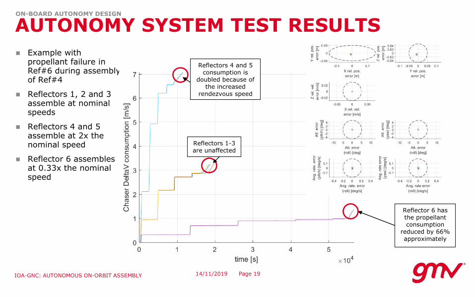
Example with propellant failure in reflector 6 during assemblyof reflector 4
– Reflectors 1, 2 and 3 perform nominal assembly (nominal speed/deltaV) before the failure
– After Ref#6 propellant loss, on-boardreplanning is launched. As result, Ref#6 is given priority and assembled next at 0.33x the nominal speed (to decreasethe required delta-V)
– After Ref#6 assembly, Ref#4 and Ref#5 are assembled at 2x the nominal speed(recovery of mission timeline byexpending additional deltaV available at Ref#4 and Ref#5)
Reflectors 4 and 5 perform the sequence faster (half duration) after replanning
Reflectors 1, 2 and 3 are not impacted by
re-planning Reflector 6 is slowed down (3x
duration) to reduce consumption
14/11/2019 Page 19IOA-GNC: AUTONOMOUS ON-ORBIT ASSEMBLY
ON-BOARD AUTONOMY DESIGN
AUTONOMY SYSTEM TEST RESULTS
Example withpropellant failure in Ref#6 during assemblyof Ref#4
Reflectors 1, 2 and 3 assemble at nominal speeds
Reflectors 4 and 5 assemble at 2x thenominal speed
Reflector 6 assemblesat 0.33x the nominal speed
Reflectors 4 and 5 consumption is
doubled because of the increased
rendezvous speed
Reflectors 1-3 are unaffected
Reflector 6 has the propellant consumption
reduced by 66% approximately