16 200/105 ed - group heshes.grouphes.com/wc/hes/duplomatic/pdf_eng/16200.pdf · 16 200/105 ed 2/12...
TRANSCRIPT

VPPL PUMP SIZE
°CAmbient temperature range
Mass
–10 / +70
008 046
— The VPPL are variable displacement axial-piston pumps withvariable swash plate, suitable for applications with opencircuits and intermediate pressures.
— They are available in five nominal sizes, with displacementsof 8, 16, 22, 36 and 46 cm3/rev.
— The pump flow rate is proportional to the rotation speed andto the angle of the swash plate, which can be continuouslymodulated. The maximum and minimum angle can be limitedmechanically via suitable regulating screws.
— They are usually supplied with a SAE J744 2-hole flange anda SAE J744 cylindrical with key shaft.
— They are available with three different types of regulatingcontrol, each according to the application needs.
VPPLVARIABLE DISPLACEMENT
AXIAL-PISTON PUMPSFOR INTERMEDIATE PRESSURE
SERIES 10
HYDRAULIC SYMBOL
OPERATING PRINCIPLE
TECHNICAL SPECIFICATIONS
8 46Maximum displacement cm3/rev
Operating pressures
Flow rate at 1500 rpm lt/min
bar
Oil volume in the pump body dm3
max 2000 - min 500Rotation speed rpm
clockwise (seen from the shaft side)
SAE flange
SAEflange J744 - 2 holes
8
0,2 0,3 0,6
23
Rotation direction
Hydraulic connection
Type of mounting
kg
20 ÷ 50
°C
see par. 2.3
cSt
Fluid temperature range
-10 / +50
Recommended viscosity
Fluid contamination degree
16 200/105 ED 1/12
16 200/105 ED
23
016 036
16 36
022
22
12 6924 5433
210
12 12

Shaft end type: cylindrical with key SAE J744
Series no: (the overall and mountingdimensions remain unchanged from10 to 19)
Hydraulic connectionS = suction / delivery: SAE flange with metric bolts
drainage with NPT threaded ports
N = NPT threaded ports (only for 008 size)
NBR sealing rings formineral oils
1 - IDENTIFICATION CODE
VPPLSERIES 10
SAE flange J744 - 2 holes
Variable displacementaxial piston pump for intermediate pressure
Pump size:008 = 8 cm3/rev016 = 16 cm3/rev022 = 22 cm3/rev036 = 36 cm3/rev046 = 46 cm3/rev
Regulator type:
PC5 = pressure regulator 210 barPCR = remote-controlled pressure regulator PQC = pressure and flow rate regulator
16 200/105 ED 2/12
V P P L - - R 0 0 / 10 N
Clockwise rotation (seen from the shaft side)
2 - HYDRAULIC FLUID
2.1 - Fluid type
Use mineral oil based hydraulic fluids, type HH, HL or HM according to ISO6743-4 standards.
The operating fluid viscosity must be within the following range:
minimum viscosity 10 cSt referred to a maximum temperature of 90 °C for the drainage fluidoptimum viscosity 20 / 50 cSt referred to the operating temperature of the fluid in the tankmaximum viscosity 1000 cSt limited only to the cold start-up of the pump, which has to be carried out with the plant at
minimum pressure.
When selecting the fluid type, be sure that the true viscosity is within the range specified above at the operating temperature.
2.2 - Fluid viscosity
2.3 - Degree of fluid contamination
The maximum degree of fluid contamination must be according to NAS 1638 class 9; therefore the use of a delivery or return filter with β20≥ 75 is suggested.A degree of maximum fluid contamination according to NAS 1638 class 7 is recommended for optimum endurance of the pump. Hence, theuse of a filter with β10 ≥ 100 is recommended.For the installation of filters on the suction line, see par. 8. The suction filter must be equipped with a by-pass valve and, if possible, with aclogging indicator and should be oversized to avoid cavitation problems.

3 - CHARACTERISTIC CURVES
3.1 - VPPL-008 PUMP CHARACTERISTIC CURVES (values obtained with mineral oil with viscosity of 36 cSt at 50°C)
VPPLSERIES 10
16 200/105 ED 3/12
210140
2
0
[l/min]
P [bar]
70
4
6
12
14
1500 rpm
1800 rpm
1500 rpm
1800 rpm
InputP
oew
r(K
W)
Q
210140
50
0
P [bar]
70
70
90
12
14
Effic
iency
nnv
(%)
Total efficiency nv
Volumetric efficiency nv
13
15
2
4
6
InputP
oew
r(K
W)
60
80
100
1500 rev
1800 rev
1500 rev
1800 rev
Q [l/min]
FLOW RATE / PRESSURE CURVES VOLUMETRIC AND TOTAL EFFICIENCY
2101400
P [bar]
70
1
2
3Q=6 l/min
Q=8 l/minQ=10 l/min
Q=12 l/min
Q=14.4 l/min
4
5
6
7
[N(KW)]
2101400
P [bar]
70
50
60
70
80
Full Cut-off
1500/1800 rev
1800 rev
1500 rev
Max. input
[dB(A)]
ABSORBED POWER NOISE LEVEL
2101400
P [bar]
70
0.5
1.0
1.5
2.0
1500 rev
1800 rev
[N(KW)]
2101400
P [bar]
70
1
2
3
Full Cut-off
Full Flow
[l/min]
Q
INPUT POWER AT FULL CUT-OFF DRAIN FLOW RATE
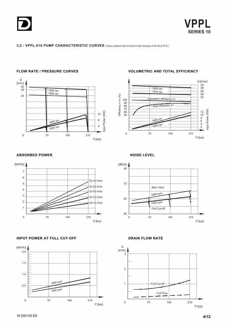
3.2 - VPPL-016 PUMP CHARACTERISTIC CURVES (values obtained with mineral oil with viscosity of 36 cSt at 50°C)
VPPLSERIES 10
16 200/105 ED 4/12
210140
4
0
[l/min]
P [bar]
70
8
12
24
28
1500 rev
1800 rev
1500 rev
1800 rev
InputP
oew
r(K
W)
Q
30
2101400
P [bar]
70
24
28
Total efficiency nv
Volumetric efficiency nv
26
30
4
8
12
1500 rev
1800 rev
1500 rev
1800 rev
22
2
6
1050
70
90
Effic
iency
nnv
(%)
60
80
100
Q [l/min]
InputP
oew
r(K
W)
FLOW RATE / PRESSURE CURVES VOLUMETRIC AND TOTAL EFFICIENCY
2101400
P [bar]
70
1
2
3
Q=10 l/min
Q=15 l/min
Q=20 l/min
Q=25 l/min
Q=30 l/min
4
5
6
7
[N(KW)]
2101400
P [bar]
70
50
60
70
80
Full Cut-off
1800 rpm
1500 rpm
Max. input
[dB(A)]
ABSORBED POWER NOISE LEVEL
2101400
P [bar]
70
0.5
1.0
1.5
2.0
1500 rpm
1800 rpm
[N(KW)]
2101400
P [bar]
70
1
2
3
Full Cut-off
Full Flow
[l/min]
Q
INPUT POWER AT FULL CUT-OFF DRAIN FLOW RATE

3.3 - VPPL-022 PUMP CHARACTERISTIC CURVES (values obtained with mineral oil with viscosity of 36 cSt at 50°C)
VPPLSERIES 10
16 200/105 ED 5/12
210140
4
0
[l/min]
P [bar]
70
8
12
30
40
1500 rpm
1800 rpm
1500 rpm
1800 rpm
InputP
oew
r(K
W)
Q
2101400
P [bar]
70
25
35
Total efficiency nv
Volumetric efficiency nv
30
40
4
8
12
1500 rpm
1800 rpm
1500 rpm
1800 rpm
2
6
10
1614
50
70
90
Effic
iency
nnv
(%)
60
80
100
Q [l/min]
InputP
oew
r(K
W)
FLOW RATE / PRESSURE CURVES VOLUMETRIC AND TOTAL EFFICIENCY
2101400
P [bar]
70
2
4
6
Q=20 l/min
Q=25 l/min
Q=30 l/min
Q=35 l/min
Q=40 l/min
8
10
12
14
[N(KW)]
16
2101400
P [bar]
70
50
60
70
80
Full Cut-off
1800 rev
1500 rev
Max. input
[dB(A)]
ABSORBED POWER NOISE LEVEL
2101400
P [bar]
70
0.5
1.0
1.5
2.0
1500 rev
1800 rev
[N(KW)]
2101400
P [bar]
70
1
2
3
Full Cut-off
Full Flow
[l/min]
Q
INPUT POWER AT FULL CUT-OFF DRAIN FLOW RATE

3.4 - VPPL-036 PUMP CHARACTERISTIC CURVES (values obtained with mineral oil with viscosity of 36 cSt at 50°C)
VPPLSERIES 10
16 200/105 ED 6/12
210140
10
0
[l/min]
P [bar]
70
20
30
60
70
1500 rev
1800 rev
1500 rev
1800 rev
InputP
oew
r(K
W)
Q
50
2101400
P [bar]
70
50
60
Total efficiency nv
Volumetric efficiency nv
55
65
30
1500 rev
1800 rev
1500 rev
1800 rev
50
70
90
Effic
iency
nnv
(%)
60
80
100
Q [l/min]
InputP
oew
r(K
W)
20
10
FLOW RATE / PRESSURE CURVES VOLUMETRIC AND TOTAL EFFICIENCY
2101400
P [bar]
70
4
8
12Q=30 l/min
Q=40 l/min
Q=50 l/min
Q=60 l/min
16
20
24
28
[N(KW)]
2101400
P [bar]
70
50
60
70
80
Full Cut-off
1800 rev
1500 rev
Max. input
[dB(A)]
ABSORBED POWER NOISE LEVEL
2101400
P [bar]
70
1
2
3
4
1500 rev
1800 rev
[N(KW)]
2101400
P [bar]
70
1
2
3
Full Cut-off
Full Flow
[l/min]
Q
INPUT POWER AT FULL CUT-OFF DRAIN FLOW RATE

3.5 - VPPL-046 PUMP CHARACTERISTIC CURVES (values obtained with mineral oil with viscosity of 36 cSt at 50°C)
VPPLSERIES 10
16 200/105 ED 7/12
210140
10
0
[l/min]
P [bar]
70
20
30
70
80
1500 rev
1800 rev
1500 rev
1800 rev
InputP
oew
r(K
W)
Q
60
2101400
P [bar]
70
65
75
Total efficiency nv
Volumetric efficiency nv
70
80
30
1500 rev
1800 rev
1500 rev
1800 rev
50
70
90
Effic
iency
nnv
(%)
60
80
100
Q [l/min]
InputP
oew
r(K
W)
20
10
FLOW RATE / PRESSURE CURVES VOLUMETRIC AND TOTAL EFFICIENCY
2101400
P [bar]
70
4
8
12
Q=40 l/min
Q=50 l/min
Q=60 l/min
Q=70 l/min
16
20
24
28
[N(KW)]
Q=80 l/min32
2101400
P [bar]
70
50
60
70
80
Full Cut-off
1800 rev
1500 rev
Max. input
[dB(A)]
ABSORBED POWER NOISE LEVEL
2101400
P [bar]
70
1
2
3
4
1500 rev
1800 rev
[N(KW)]
2101400
P [bar]
70
1
2
3
Full Cut-off
Full Flow
[l/min]
Q
INPUT POWER AT FULL CUT-OFF DRAIN FLOW RATE

The PC5 pressure regulator keeps the pressure at a constantset level in the circuit, thus adjusting automatically the pumpflow rate according to the real need of the system.
The desired pressure can be set by manually adjusting the Pregulation valve. The clockwise rotation of the adjustment boltmakes the pressure increase.
FEATURES OF THE PC REGULATOR:
- P pressure adjustment range = 40 ÷ 210 bar
4 - TYPES OF REGULATORS
4.1 - PRESSURE REGULATOR: PC5
16 200/105 ED 8/12
VPPLSERIES 10
4.2- REMOTE-CONTROLLED PRESSURE REGULATOR: PCR
OUT
IN D2 D1
X
Escluso dalla fornitura The PCR regulator allows a remote-control of the device via aremote control connected to the X port (typical application forsubmerged pumps).
In case a pressure regulating valve is used for the remote-control, itis suggested to use a direct operated valve with a size suitable to1,5 l/min pilot flow rate.
Note: The maximum length of the connection between the valveand X port of the pump must not be longer than 2 m.
FEATURES OF THE PCR REGULATOR:
- remote-adjustment pressure = 20 ÷ 210 bar- flow rate available on the X port for the remote-control = about 1,5 l/min (approx.)
4.3 - PRESSURE AND FLOW RATE REGULATOR: PQC
This regulator, in addition to the pressure adjustment (as for the PC5model), allows the pump flow rate control, according to the ∆ppressure drop measured on either side of a throttle valve installedon the user line.
Note: The connection pipe between the X port and the flow linedownstream the restrictor (or valve) must always be made(customer charge).
FEATURES OF THE PQC REGULATOR:
- P pressure adjustment range = 40 ÷ 210- Q differential pressure adjustment range = 16 ÷ 28 bar- minimum delivery pressure = 20 bar
Not included in the supply
Not included in the supply

Key 4.76+0.01
0
0
0
12
3 4
5
6
-0.05
-0.021
-0.25
-0.01
INOUT
5
6
7711
49
6
142
14
43.5
214(MAX)
510
149.5
11
127.5
106.4
110
130
ø21.2
ø19.05
42,5
25
ø82.55
78
53.2
18
164.5(MAX) 49.547
29
3
132
16 200/105 ED 9/12
VPPLSERIES 10
5 - VPPL-008 PUMPS OVERALL AND MOUNTING DIMENSIONS
VPPL-008PC5 PUMPS
7893
93.5
78
VPPL-008PCR PUMPS
10
78
123
93.5
79
108
VPPL-008PQC PUMPS
dimensions in mm
Suction port IN: 1/2” NPT
Delivery port OUT: 1/2” NPT
2
1
Pressure adjustment bolt (forPC5 version)
Filling plug
Flow adjustment bolt
Differential pressure (notadjustable)
Pressure remote-setting port(for PCR version): 1/4” NPT
Load Sensing port (for PQCversion): 1/4” NPT
Pressure adjustment bolt (forPQC version)
3
Drainage port: 3/8” NPT
4
5
6
7
8
9
10

4 fori M10x16
0
Key 4.76 -0.01
-0.05
+0.01
-0.021
0
0
12
43
5
6
-0.25
INOUT
30 2
6
49
23
245(MAX)
181
153ø21.2
ø19.05
55
47.5
22
ø24
ø82.55
13
77
3
82
137
84.5
150.5
130
124
106.4
11 52
42
16 200/105 ED 10/12
VPPLSERIES 10
6 - VPPL-016 and VPPL-022 PUMPS OVERALL AND MOUNTING DIMENSIONS
VPPL-016PC5 and VPPL-022PC5 PUMPS
7388
105
78
VPPL-016PCR and VPPL-022PCR PUMPS
73
118
105
79
103
10
VPPL-016PQC and VPPL-022PQC PUMPS
Suction port IN: SAE 3000 1”flange (see par. 9)
Delivery port OUT: SAE 30003/4” flange (see par. 9)
2
1
Pressure adjustment bolt (forPC5 version)
Filling plug
Flow adjustment bolt
Differential pressure (notadjustable)
Pressure remote-setting port(for PCR version): 1/4” NPT
Load Sensing port (for PQCversion): 1/4” NPT
Pressure adjustment bolt (forPQC version)
3
Drainage port: 3/8” NPT
4
5
6
7
8
9
10
dimensions in mm
VPPLSERIES 10
4 fori M10x16
-0.01+0.01
Key 6.3
2 1
43
0-0.05
-0.021
0
0
6
5
-0.25
INOUT
181
64
144
146
170
ø101.6
ø22.23
ø25.08
ø30
52.4
15
222
190
26.2
300(MAX)
240(MAX)
68
93
53(MIN)
6 54
53
38 4
95
60
173170
70
45
13
16 200/105 ED 11/12
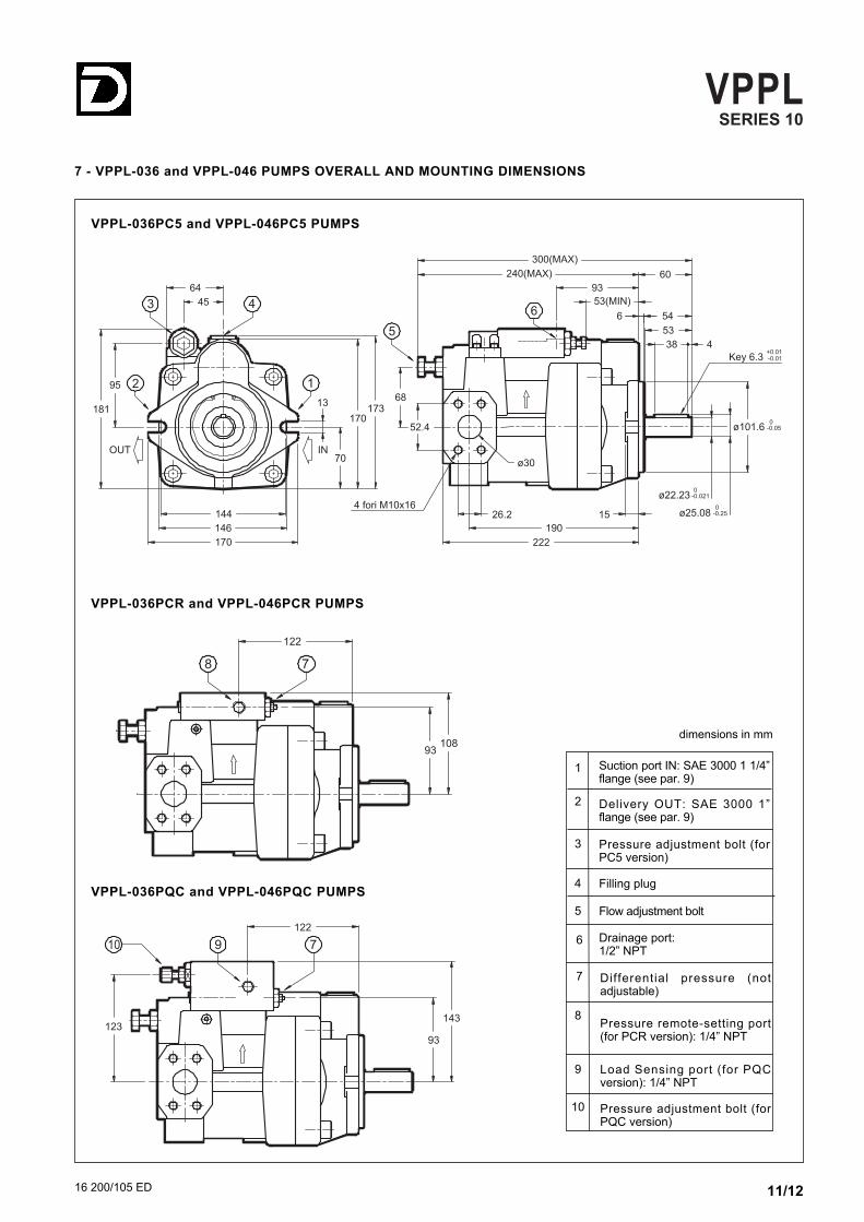
7 - VPPL-036 and VPPL-046 PUMPS OVERALL AND MOUNTING DIMENSIONS
VPPL-036PC5 and VPPL-046PC5 PUMPS
93108
122
78
VPPL-036PCR and VPPL-046PCR PUMPS
93
143
122
79
123
10
VPPL-036PQC and VPPL-046PQC PUMPS
Suction port IN: SAE 3000 1 1/4”flange (see par. 9)
Delivery OUT: SAE 3000 1”flange (see par. 9)
2
1
Pressure adjustment bolt (forPC5 version)
Filling plug
Flow adjustment bolt
Differential pressure (notadjustable)
Pressure remote-setting port(for PCR version): 1/4” NPT
Load Sensing port (for PQCversion): 1/4” NPT
Pressure adjustment bolt (forPQC version)
3
Drainage port: 1/2” NPT
4
5
6
7
8
9
10
dimensions in mm

REPRODUCTION IS FORBIDDEN, THE COMPANY RESERVED THE RIGHT TO APPLY ANY MODIFICATIONS
DUPLOMATIC OLEODINAMICA SpA20025 LEGNANO (MI) - P.le Bozzi, 1 / Via EdisonTel. 0331/472111 - Fax 0331/548328
M10 x 35
OR 4150SAE - 1 1/4” 1 1/4” BSP 32 21 41 22 30,2 58,7 68
OR 4131SAE - 1” 1” BSP 25 18 38 22 26,2 52,4 55
OR 4100SAE - 3/4” 3/4” BSP 19 18 36 19 22,2 47,6 50
14 bolts 2Flange
descriptionFlangecode ∅A ∅B C D E F G H
79
70
65
L
dimensions in mm
Bolts and O-rings must be ordered separately.
9 - SAE 3000 CONNECTION FLANGES
0610719
0610713
0610720
pmax[bar]345
345
276
VPPLSERIES 10
16 200/105 ED 12/12
8 - INSTALLATION
- The VPPL pumps can be installed both in a horizontal and vertical position, with the shaft in an upward position.Note: The drainage port has to be oriented so that the oil level inside the pump body is never lower than 3/4 of its volume.
- In the case of installation above the oil level, check that the min. suction pressure is not lower than -0.2 bars (relative). If a low noise emissionlevel is required, the installation inside the tank is suggested. In case of an installation inside the tank, with an oil level which does not grant complete pump submersion, it is suggested that the drain tubeis adjusted so that the pump higher bearing can be always lubricated.
- Before starting, the pump body has to be filled with the fluid.
- Check the rotation direction of the pump.
- It is necessary to vent the air from the delivery connection before operating it the first time. If the air venting should be difficult, the use of aventing valve is recommended. The pump start up, especially at a cold temperature, should occur with the plant at minimum pressure.
-The suction tube has to be suitably sized so that the suction pressure is never lower than -0.2 bar (relative). Bends or restrictions or anexcessive tube length could further decrease the value of the suction pressure with a following increase in the noise emissions and adecrease in the pump lifetime.
- The drainage tube has to be sized so that the pressure inside the pump body is always lower than 0.5 bars (relative), even during thedynamic change and flow rate phases. The minimum piping size is 3/8” for the pump type 008, 016 and 022, while it should be at least 1/2”for the pumps type 036 and 046. The drainage tube has to unload inside the tank far from the suction area.
- No check valves allowed on the suction line. As for details and the installation of filter elements, see par. 2.3.
- The motor-pump connection must be carried out directly with a flexible coupling, to reduce at the minimum the axial and radial loads on thepump shaft. The alignment tolerance between the two shafts must be within 0,05 mm.