16 bit digital adders - concordia...
TRANSCRIPT

Parallel Adders

2
Introduction
Binary addition is a fundamental operation in most digital circuits
There are a variety of adders, each has certain performance.
Each type of adder is selected depending on where the adder is to be used.

3
Adders
Basic Adder Unit
Ripple Carry Adder
Carry Skip Adders
Carry Look Ahead Adder
Carry Select Adder
Pipelined Adder
Manchester carry chain adder
Multi-operand Adders
Pipelined and Carry save adders

4
Basic Adder Unit
A combinational circuit that adds two bits is called a half adder
A full adder is one that adds three bits, the third produced from a previous addition operation
P
G

5
•Reuse carry term to implement full adder
2. A brief introduction to
Ripple Carry Adder
Figure 2.2 1bit full adder CMOS complementary implementation

6
Ripple Carry Adder
The ripple carry adder is constructed by cascading full adder blocks in series
The carryout of one stage is fed directly to the carry-in of the next stage
For an n-bit parallel adder, it requires n full adders

7
Figure2.3 RCA implementation

8
Ripple Carry Drawbacks
Not very efficient when large bit numbers are used
Delay increases linearly with the bit length

9
•Delay
Critical path in a 4-bit ripple-carry adder
Note: delay from carry-in to carry-out is more important than from A to carry-out or
from carry-in to SUM, because the carry-propagation chain will determine the latency
of the whole circuit for a Ripple-Carry adder.

10
•Delay
The latency of a 4-bit ripple carry adder can be
derived by considering the above worst-case signal
propagation path. We can thus write the following
expression:
TRCA-4bit = TFA(A0,B0→Co)+T FA (C in→C1)+TFA (Cin→C2)+ TFA (Cin→S3)
And, it is easy to extend to k-bit RCA:
TRCA-4bit = TFA(A0,B0→Co)+(K-2)* TFA (Cin→Ci)+TFA (Cin→Sk-1)

11
Schematic diagram of a 4-bit adder
No reference to implementation method
Performance is important
Design requirements

12
Comparison of CMOS and TG Logic
•Simulation result
4-bit RCA performance comparison of CMOS and TG logic
(min size)

13
Comparison of CMOS and TG Logic
•Simulation result
4-bit RCA performance comparison of CMOS and TG logic
(Wp/Wn=2/1)

14
Carry Look-Ahead Adder
Calculates the carry signals in advance, based on the input signals
Boolean Equations
Pi = Ai Bi Carry propagate
Gi = AiBi Carry generate
Si = Pi Ci Sum
Ci+1= Gi + PiC Carry out
Signals P and G only depend on the input bits

15
Carry Look-Ahead Adder
Applying these equations for a 4-bitadder:
C1 = G0 + P0C0
C2 = G1 + P1C1 = G1 + P1(G0 + P0C0) = G1 + P1G0 + P1P0C0
C3 = G2 + P2C2 = G2 + P2G1 + P2P1G0 + P2P1P0C0
C4 = G3 + P3C3 = G3 + P3G2 + P3P2G1 + P3P2P1G0 + P3P2P1P0C0

16
Carry Look-Ahead Structure
Propagate/Generate Generator
Look-Ahead Carry generator
Sum generator
Ai
Bi
Gi
Pi
Ci
Si
Pi
17
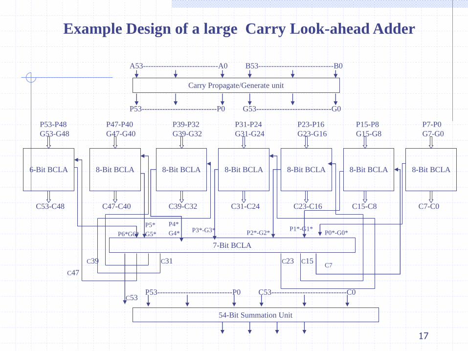
Example Design of a large Carry Look-ahead Adder
Carry Propagate/Generate unit
8-Bit BCLA8-Bit BCLA8-Bit BCLA8-Bit BCLA8-Bit BCLA8-Bit BCLA6-Bit BCLA
A53-----------------------------A0 B53-----------------------------B0
P53-----------------------------P0 G53-----------------------------G0
7-Bit BCLA
P53-P48
G53-G48
P47-P40
G47-G40
P39-P32
G39-G32
P31-P24
G31-G24
P23-P16
G23-G16
P15-P8
G15-G8
P7-P0
G7-G0
C53-C48 C47-C40 C39-C32 C31-C24 C23-C16 C15-C8 C7-C0
P0*-G0* P1*-G1*
P2*-G2* P3*-G3*P4*
G4*
P5*
G5*P6*G6*
C7C15C23C31C39
C47
C53
54-Bit Summation Unit
P53-----------------------------P0 C53-----------------------------C0

18
Carry Skip Adders
Are composed of ripple carry adder blocks of fixed size* and a carry skip chain
The size of the blocks are chosen so as to minimize the longest life of a carry

19
Carry Skip Mechanics
Boolean Equations
Carry Propagate: Pi = Ai Bi
Sum: Si = Pi Ci
Carry Out: Ci+1= Ai Bi + Pi Ci
Worthwhile to note:
If Ai = Bi then Pi = 0, making the carry out, Ci+1, depend only on Ai and Bi Ci+1= Ai Bi
•Ci+1 = 0 if Ai = Bi = 0
•Ci+1 = 1 if Ai = Bi = 1
Alternatively if Ai Bi then Pi = 1 Ci+1= Ci

20
Carry Skip (example)Two Random Bit Strings:
A 10100 01011 10100 01011
B 01101 10100 01010 01100
block 3 block 2 block 1 block 0
•compare the two binary strings inside each block
•If all the bits inside are unequal, block 2, then the carry in from block 1 is propagated to block 3
•Carry-ins from block 2 receive the carry in from block 1
•If there exists a pair of bits that is equal carry skip mechanism fails

21
Carry Skip Chain

22
Manchester Carry Adder
Boolean Equations:
1) Gi = Ai Bi --carry generate of ith stage
2) Pi = Ai Bi --carry propagate of ith stage
3) Si = Pi Ci --sum of ith stage
4) Ci+1 = Gi + PiCi --carry out of ith stage

23
Manchester Carry Adder

24
Manchester Carry Adder

25
Carry Select Adder Example 4-bit Adder
Is composed of two four-bit ripple carry adders per section
Both sum and carry bits are calculated for the two alternatives of the input carry, “0” and “1”

26
Carry Select (Mechanics)
The carry out of each section determines the carry in of the next section, which then selects the appropriate ripple carry adder
The very first section has a carry in of zero
Time delay: time to compute first section + time to select sum from subsequent sections

27
Carry Select Adder Design
The Square Root and Linear Carry Select Adder
The linear carry-select adder is constructed by chaining a number of equal-length adder stages
Square Root carry-select adder is constructed by Equalizing the delay through two carry chains and the block-multiplexer signal from previous stage

28
Carry Select Adder Design
The Square Root and Linear Carry Select Adder
The linear carry-select adder is constructed by chaining a number of equal-length adder stages
Square Root carry-select adder is constructed by Equalizing the delay through two carry chains and the block-multiplexer signal from previous stage

29
Carry Select Adder Design (example 19-bit)
.
Setup
0-Carry
Sum
generation
Multiplexer
1-Carry
0
1
Ci.0
Setup
0-Carry
Sum
generation
Multiplexer
1-Carry
Setup
0-Carry
Sum
generation
Multiplexer
1-Carry
Setup
0-Carry
Sum
generation
Multiplexer
1-Carry
Bit 0-3 Bit 4-7 Bit 8-11 Bit 12-15
0
1
0
1
0
1
(1)
(1)
(5) (5)
(6) (7) (8)
S0-3 S4-7 S8-11 S12-15
(a) Linear configuration
Setup
0-Carry
Sum
generation
Multiplexer
1-Carry
0
1
(9)
(11)
(10)
Bit 16-19
S16-19

30
Carry Select Adder Design
.
Worse-case signal arrival time in carry select adders
The signal arrival time are mark in ()
Setup
0-Carry
Sum
generation
Multiplexer
1-Carry
0
1
Setup
0-Carry
Sum
generation
Multiplexer
1-Carry
Setup
0-Carry
Sum
generation
Multiplexer
1-Carry
Setup
0-Carry
Sum
generation
Multiplexer
1-Carry
Bit 0-1 Bit 2-4 Bit 5-8 Bit 9-13
0
1
0
1
0
1
(1)
(1)
(3) (3)
(4) (5) (6) (7)
S0-1 S2-4 S5-8 S9-13
(b) Square root configuration
(10)Sum
generation
Multiplexer
(8)
(9)S14-19
(7)
Bit 14-19

31
Multi-Operand and Pipelining

32
A B C A B C A B CA B CB C BB B
A B CB C A B CB C A B CB CA B CB C
Signal propagation in serial blocks
Signal Propagation in Pipelined serial Blocks

33
Pipelined Adder
The added complexity of such a pipelined adder pays off if long sequences of numbers are being added.

34
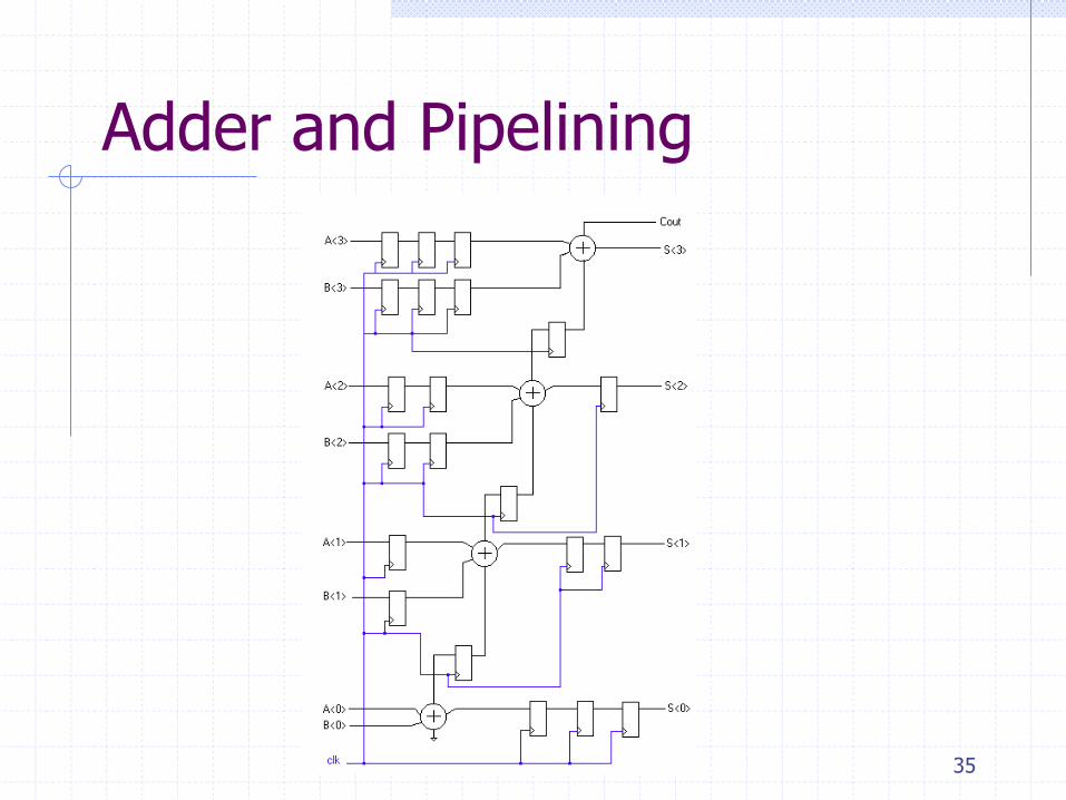
Pipelined Adder
Pipelining a design will increase its throughput
The trade-off is the use of registers
If pipelining is to be useful these three points hasto be present:
-It repeatedly executes a basic function.
-The basic function must be divisible intoindependent stages having minimaloverlap with each other.
-The stages must be of similar complexity
35
Adder and Pipelining

36
Carry Save adder

37
Parallel Prefix Adder[13,15,2]
The parallel prefix adder is a kind of carry look-ahead adders that accelerates a n-bit addition by means
of a parallel prefix carry tree.
A block diagram of a prefix adder
Input bit propagate, generate, and not kill cells
Output sum cells
The prefix carry tree
z toup x from bits theacross signal generate" group" x
zG
z toup x from bits theacross signal kill"not group" x
zK
16-bit Ladner-Fiacher parallel prefix tree
black cell grey cell
16

38
Flagged Prefix Adder[13,15]
Block diagram of a flagged prefix adder The parallel prefix adder may be modified slightly to
support late increment operations. If the output grey
cells are replaced by black cells so that both and
signals are returned, a sum may be incremented
readily.
17

39
Reference List[1] Reduced latency IEEE floating-point standard adder architectures. Beaumont-Smith, A.; Burgess, N.; Lefrere, S.; Lim, C.C.; Computer Arithmetic,
1999. Proceedings. 14th IEEE Symposium on , 14-16 April 1999
[2] M.D. Ercegovac and T. Lang, “Digital Arithmetic.” San Francisco: Morgan Daufmann, 2004.
[3] Using the reverse-carry approach for double datapath floating-point addition. J.D. Bruguera and T. Lang. In Proceedings of the 15th IEEE
Symposium on Computer Arithmetic, pages 203-10.
[4] A low power approach to floating point adder design. Pillai, R.V.K.; Al-Khalili, D.; Al-Khalili, A.J.; Computer Design: VLSI in Computers and
Processors, 1997. ICCD '97. Proceedings. 1997 IEEE International Conference on, 12-15 Oct. 1997 Pages:178 – 185
[5] An IEEE compliant floating-point adder that conforms with the pipeline packet-forwarding paradigm. Nielsen, A.M.; Matula, D.W.; Lyu, C.N.;
Even, G.; Computers, IEEE Transactions on, Volume: 49 , Issue: 1, Jan. 2000 Pages:33 - 47
[6] Design and implementation of the snap floating-point adder. N. Quach and M. Flynn. Technical Report CSL-TR-91-501, Stanford University, Dec.
1991.
[7] On the design of fast IEEE floating-point adders. Seidel, P.-M.; Even, G. Computer Arithmetic, 2001. Proceedings. 15th IEEE Symposium on , 11-13
June 2001 Pages:184 – 194
[8] Low cost floating point arithmetic unit design. Seungchul Kim; Yongjoo Lee; Wookyeong Jeong; Yongsurk Lee; ASIC, 2002. Proceedings. 2002
IEEE Asia-Pacific Conference on, 6-8 Aug. 2002 Pages:217 - 220
[9] Rounding in Floating-Point Addition using a Compound Adder. J.D. Bruguera and T. Lang. Technical Report. University of Santiago de
Compostela. (2000)
[10] Floating point adder/subtractor performing ieee rounding and addition/subtraction in parallel. W.-C. Park, S.-W. Lee, O.-Y. Kown, T.-D. Han,
and S.-D. Kim. IEICE Transactions on Information and Systems, E79-D(4):297–305, Apr. 1996.
[11] Efficient simultaneous rounding method removing sticky-bit from critical path for floating point addition. Woo-Chan Park; Tack-Don Han;
Shin-Dug Kim; ASICs, 2000. AP-ASIC 2000. Proceedings of the Second IEEE Asia Pacific Conference on , 28-30 Aug. 2000 Pages:223 – 226
[12] Efficient implementation of rounding units Burgess. N.; Knowles, S.; Signals, Systems, and Computers, 1999. Conference Record of the Thirty-
Third Asilomar Conference on, Volume: 2, 24-27 Oct. 1999 Pages: 1489 - 1493 vol.2
[13] The Flagged Prefix Adder and its Applications in Integer Arithmetic. Neil Burgess. Journal of VLSI Signal Processing 31, 263–271, 2002
[14] A family of adders. Knowles, S.; Computer Arithmetic, 2001. Proceedings. 15th IEEE Symposium on , 11-13 June 2001 Pages:277 – 281
[15] PAPA - packed arithmetic on a prefix adder for multimedia applications. Burgess, N.; Application-Specific Systems, Architectures and Processors,
2002. Proceedings. The IEEE International Conference on, 17-19 July 2002 Pages:197 – 207
[16] Nonheuristic optimization and synthesis of parallelprefix adders. R. Zimmermann, in Proc. Int.Workshop on Logic and Architecture Synthesis,
Grenoble, France, Dec. 1996, pp. 123–132.
[17] Leading-One Prediction with Concurrent Position Correction. J.D. Bruguera and T. Lang. IEEE Transactions on Computers. Vol. 48. No. 10. pp.
1083-1097. (1999)
[18] Leading-zero anticipatory logic for high-speed floating point addition. Suzuki, H.; Morinaka, H.; Makino, H.; Nakase, Y.; Mashiko, K.; Sumi, T.;
Solid-State Circuits, IEEE Journal of , Volume: 31 , Issue: 8 , Aug. 1996 Pages:1157 – 1164
[19] An algorithmic and novel design of a leading zero detector circuit: comparison with logic synthesis. Oklobdzija, V.G.; Very Large Scale
Integration (VLSI) Systems, IEEE Transactions on, Volume: 2 , Issue: 1 , March 1994 Pages:124 – 128
[20] Design and Comparison of Standard Adder Schemes. Haru Yamamoto, Shane Erickson, CS252A, Winter 2004, UCLA

40
Comparisons
Adder Number of
CLBs
Delay
(ns)
Area Power Consumption
(W)Ripple-Carry 16 212.79 40.00 1.7318
Carry Look-Ahead 34 143.69 51.00 1.9668
Carry-Select 44 102.74 108.00 3.3595
Which one should we choose?

41
For this comparison Synopsys tools were used to perform logic synthesis.
• The implemented VHDL codes for all the 64-bit adders are translated into net list files.
• The virtex2 series library, XC2V250-4_avg, is used in those 64-bit adders synthesis and targeting
•After synthesizing, the related power consumption, area, and propagation delay are reported.

42
Synthesis result parameter comparison listings:
Primitive Component Delay (ns) Area Power (W) AT AT2 PD
4-bit carry ripple adder 72.1 160 0.8745784 11536 831745.6 63.058
8-bit carry ripple adder 72.1 160 0.8745784 11536 831745.6 63.058
16-bit carry ripple adder 72.1 160 0.8745784 11536 831745.6 63.058
4-bit carry look-ahead adder 93.54 288 1.049 26939.52 2519922 98.12346
8-bit carry look-ahead adder 118.9 302 1.1627 35907.8 4269437 138.25
16-bit carry look-ahead adder 124.3 310 1.1757 38533 4789651 146.14
two-level 8-bit carry look-ahead
adder 31.57 434 1.348 13701.38 432552 42.56
4-bit carry select adder 24.72 422.5 1.6351 10444.2 258180 40.42
8-bit carry select adder 20.48 394.5 1.5757 8079.36 165465 32.27
16-bit carry select adder 26 356.5 1.4792 9269 240994 38.4592
Nonlinear Carry select adder 17.94 412 1.6267 7391.28 132599 29.183
4-bit Manchester adder 27.58 256 1.0857 7060.48 194728 29.9436
8-bit Manchester adder 27.58 256 1.0857 7060.48 194728 29.9436
16-bit Manchester adder 27.58 256 1.0857 7060.48 194728 29.9436
16-bit Ladner-Fischer prefix
adder 24.79 326 1.23 8081.54 200341 30.4917
16-bit Brent-Kung prefix adder 26.94 290 1.15 7812.6 210471 30.981
16-bit Han-Carlson prefix adder 25.43 326 1.2758 8290.18 210819 32.4436
16-bit Kogge-Stone prefix adder 25.59 428 1.5546 10952.52 280274 39.78
64-bit Kogge-Stone adder 11.97 611 1.919 7313.67 87544 22.97

43
Compound Adder Design[2,13-16,20]
The Prefix Adder Scheme is chosen.
Advantages:Simple and regular structure
Well-performance
A wide range of area-delay trade-offs
Moreover, the Flagged Prefix Adder is
particular useful in compound adder
implementation because, unlike other adder
schemes which need a pair of adders to
obtain sum and sum+1 simultaneously, it
only use one adder.
15

44
synthesis and targeting
Synopsys tools are used to perform logic synthesis.
the implemented VHDL codes for all the 64-bit adders are translated into net list files.
The virtex2 series library, XC2V250-4_avg, is used in those 64-bit adders synthesis and targeting because the area and the propagation delay is suitable for these adders.
After synthesizing, the related power consumption, area, and propagation delay are reported.
From the synthesis, the related FPGA layout schematic is reported.

45
64-bit adders comparison

46

47

48
The power is not in scale(*100).
49
64-bit adders conclusion
Adders can be implemented in different methods according to the different requirements.
Each kind of adder has different properties in area, propagation delay, and power consumption.
There is no absolute advantages or disadvantages for an adder, and usually, one advantage compensates with another disadvantage.
A ripple carry adder is easy to implemented, and for short bit length, the performances are good.
For long bit length, a carry look-ahead adder is not practical, but a hierarchical structure one can improve much.

50
A carry select adder has good performance in propagation delay especially the nonlinear one; however, it compensates with large area.
In these 64-bit adders, the Manchester carry adder has the best performance when considered all of the propagation delay, area, and power consumption.
The parallel prefix adder has good performance in propagation delay, but the area becomes large.
The 64-bit Kogge-Stone prefix adder has the shortest propagation delay, but it has the largest area and power consumption as well.

51

52
Ripple Carry’s VHDL
library IEEE;
use ieee.std_logic_1164.all;
entity ripple_carry is
port( A, B : in std_logic_vector( 15 downto 0);
C_in : in std_logic;
S : out std_logic_vector( 15 downto 0);
C_out : out std_logic);
end ripple_carry;
architecture RTL of ripple_carry is
begin
process(A, B, C_in)
variable tempC : std_logic_vector( 16 downto 0 );
variable P : std_logic_vector( 15 downto 0 );
variable G : std_logic_vector( 15 downto 0 );
begin

53
Ripple Carry’s VHDL
tempC(0) := C_in;
for i in 0 to 15 loop
P(i):=A(i) xor B(i);
G(i):=A(i) and B(i);
S(i)<= P(i) xor tempC(i);
tempC(i+1):=G(i) or (tempC(i) and P(i));
end loop;
C_out <= tempC(16);
end process;
end;
P
G

54
Carry Select’s VHDL (ripple4)
Two four-bit ripple carry adders were used to build a carry select section of the same size
Four 4-bit carry select sections were used as components in building our 16 bit adders
ripple_carry4
library IEEE;
use ieee.std_logic_1164.all;
entity ripple_carry4 is
port( e, f : in std_logic_vector( 3 downto 0);
carry_in : in std_logic;
S : out std_logic_vector( 3 downto 0);
carry_out : out std_logic);
end ripple_carry4;

55
Carry Select’s VHDL (ripple4)architecture RTL of ripple_carry4 is
begin
process(e, f, carry_in)
variable tempC : std_logic_vector( 4 downto 0 );
variable P : std_logic_vector( 3 downto 0 );
variable G : std_logic_vector( 3 downto 0 );
begin
tempC(0) := carry_in;
for i in 0 to 3 loop
P(i):=e(i) xor f(i);
G(i):=e(i) and f(i);
S(i)<= P(i) xor tempC(i);
tempC(i+1):=G(i) or (tempC(i) and P(i));
end loop;
carry_out <= tempC(4);
end process;
end;

56
Carry Select’s VHDL (select4)
carry_select4
library IEEE;
use ieee.std_logic_1164.all;
entity carry_select4 is
port( c, d : in std_logic_vector( 3 downto 0);
C_input : in std_logic;
Result : out std_logic_vector( 3 downto 0);
C_output : out std_logic);
end carry_select4;
architecture RTL of carry_select4 is
component ripple_carry4
port( e, f : in std_logic_vector( 3 downto 0);
carry_in : in std_logic;
S : out std_logic_vector( 3 downto 0);
carry_out : out std_logic);
end component;

57
Carry Select’s VHDL (select4)
For S0: ripple_carry4 Use entity work.ripple_carry4(RTL);
For S1: ripple_carry4 Use entity work.ripple_carry4(RTL);
signal SUM0, SUM1 : std_logic_vector( 3 downto 0 );
signal carry0, carry1 : std_logic;
signal zero, one : std_logic;
begin
zero<='0';
one<='1';
S0: ripple_carry4 port map( e=>c, f=>d, carry_in=>zero, S=>SUM0,
carry_out=>carry0 );
S1: ripple_carry4 port map( e=>c, f=>d, carry_in=>one, S=>SUM1,
carry_out=>carry1 );
Result<=SUM0 when C_input='0' else
SUM1 when C_input='1' else
"ZZZZ";
C_output<= (C_input and carry1) or carry0;
end;

58
Carry Select’s VHDL (select16)
carry_select16
library IEEE;
use ieee.std_logic_1164.all;
entity carry_select16 is
port( A, B : in std_logic_vector( 15 downto 0);
C_in : in std_logic;
SUM : out std_logic_vector( 15 downto 0);
C_out : out std_logic);
end carry_select16;
architecture RTL of carry_select16 is
component carry_select4
port( c, d : in std_logic_vector( 3 downto 0);
C_input : in std_logic;
Result : out std_logic_vector( 3 downto 0);
C_output : out std_logic);
end component;

59
Carry Select’s VHDL (select16)
For S0: carry_select4 Use entity work.carry_select4(RTL);
For S1: carry_select4 Use entity work.carry_select4(RTL);
For S2: carry_select4 Use entity work.carry_select4(RTL);
For S3: carry_select4 Use entity work.carry_select4(RTL);
signal tempc1, tempc2, tempc3 : std_logic;
begin
S0: carry_select4 port map( c=>A ( 3 downto 0 ), d =>B ( 3 downto 0 ),
C_input=>C_in, Result=>SUM ( 3 downto 0 ), C_output=>tempc1 );
S1: carry_select4 port map( c=>A ( 7 downto 4 ), d =>B ( 7 downto 4 ),
C_input=>tempc1, Result=>SUM ( 7 downto 4 ), C_output=>tempc2 );
S2: carry_select4 port map( c=>A ( 11 downto 8 ), d =>B ( 11 downto 8 ),
C_input=>tempc2, Result=>SUM ( 11 downto 8 ), C_output=>tempc3 );
S3: carry_select4 port map( c=>A ( 15 downto 12 ), d =>B ( 15 downto 12
), C_input=>tempc3, Result=>SUM ( 15 downto 12 ), C_output=>C_out );
end;

60
Carry Look-Ahead’s VHDL
half_adder
library IEEE;
use ieee.std_logic_1164.all;
entity half_adder is
port( A, B : in std_logic_vector( 16 downto 1 );
P, G : out std_logic_vector( 16 downto 1 ) );
end half_adder;
architecture RTL of half_adder is
begin
P <= A xor B;
G <= A and B;
end;
61
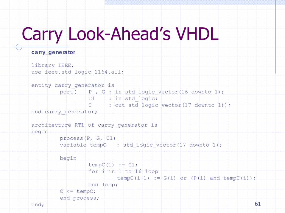
Carry Look-Ahead’s VHDLcarry_generator
library IEEE;
use ieee.std_logic_1164.all;
entity carry_generator is
port( P , G : in std_logic_vector(16 downto 1);
C1 : in std_logic;
C : out std_logic_vector(17 downto 1));
end carry_generator;
architecture RTL of carry_generator is
begin
process(P, G, C1)
variable tempC : std_logic_vector(17 downto 1);
begin
tempC(1) := C1;
for i in 1 to 16 loop
tempC(i+1) := G(i) or (P(i) and tempC(i));
end loop;
C <= tempC;
end process;
end;

62
Carry Look-Ahead’s VHDLLook_Ahead_Adder
library IEEE;
use ieee.std_logic_1164.all;
entity Look_Ahead_Adder is
port( A, B : in std_logic_vector( 16 downto 1 );
carry_in : in std_logic;
carry_out : out std_logic;
S : out std_logic_vector( 16 downto 1 ) );
end Look_Ahead_Adder;
architecture RTL of Look_Ahead_Adder is
component carry_generator
port( P , G : in std_logic_vector(16 downto 1);
C1 : in std_logic;
C : out std_logic_vector(17 downto 1));
end component;

63
Carry Look-Ahead’s VHDL
component half_adder
port( A, B : in std_logic_vector( 16 downto 1 );
P, G : out std_logic_vector( 16 downto 1) );
end component;
For CG: carry_generator Use entity work.carry_generator(RTL);
For HA: half_adder Use entity work.half_adder(RTL);
signal tempG, tempP : std_logic_vector( 16 downto 1 );
signal tempC : std_logic_vector( 17 downto 1 );
begin
HA: half_adder port map( A=>A, B=>B, P =>tempP, G=>tempG );
CG: carry_generator port map( P=>tempP, G=>tempG, C1=>carry_in, C=>tempC );
S <= tempC( 16 downto 1 ) xor tempP;
carry_out <= tempC(17);
end;

64
Ripple carry adder
Block diagram:
Critical path:

65
Carry look-ahead adderPi = Ai ⊕ Bi Carry propagateGi= Ai.Bi Carry generateSi = Pi ⊕ Ci Summation
Ci+1 = Gi + PiCi Carryout
C0 = Cin;C1 = G (0) + (P(0)C0);C2 = G (1) + (P (1)G (0)) + (P(1) P(0)C0);C3 = G (2) + (P(2) G(1)) + (P(2)P(1)G(0)) + (P(2)P(1)P(0) C0);C4 = G(3) + (P(3) G(2)) + (P(3) P(2) G(1)) + (P(3) P(2) P(1)
G(0)) + (P(3)P(2) P(1) P(0)C0);…………………………………………………Ci+1= Gi + PiGi-1 + PiPi-1Gi-2 + …PiPi-1….P2P1G0 + PiPi-
….P1P0C0.

66
Carry look-ahead adder
Block diagram
When n increases, it is not practical to use standard carry look-ahead adder since the fan-out of carry calculation becomes very large.
A hierarchical carry look-ahead adder structure could be implemented.

67
Hierarchical 2- level 8-bit carry look-ahead adder

68
Carry select adder
compute alternative results in parallel and subsequently select the carry input which is calculated from the previous stage.
compensate with an extra circuit to calculate the alternative carry input and summation result.
need multiplexer to select the carry input for the next stage and the summation result.
the drawback is that the area increases.
time delay=time to compute the first section + time to select sum from subsequent section.
The summation part could be implemented by ripple carry adder, Manchester adder, carry look-ahead adder as well as prefix adder…...

69
Carry select adder
block diagram

70
Carry select adder
For an n bit adder, it could be implemented with equal length of carry select adder, and this is called linear carry select adder.
However. the linear carry select adder does not always have the best performance.
A carry select adder can be implemented in different length, and this is called nonlinear carry select adder.
A 64-bit adder can be implemented in 4, 4, 5, 6, 7, 8, 9, 10,11 bit nonlinear structure.
The performance of 64-bit nonlinear carry select adder is better than linear one in propagation delay.

71
64-bit nonlinear carry select adder
Block diagram
72
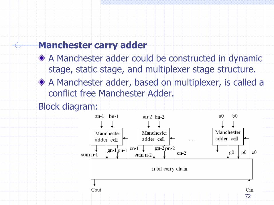
Manchester carry adder
A Manchester adder could be constructed in dynamic stage, static stage, and multiplexer stage structure.
A Manchester adder, based on multiplexer, is called a conflict free Manchester Adder.
Block diagram:
73
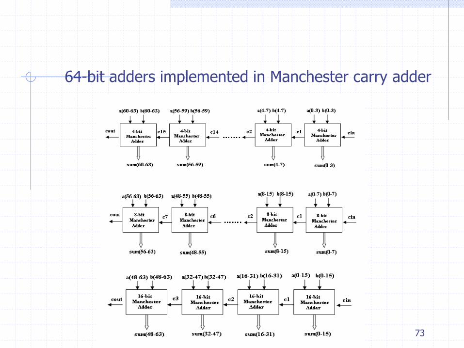
64-bit adders implemented in Manchester carry adder

74
Parallel prefix adderlike a carry look-ahead adder, the prefix adder accelerates addition by the parallel prefix carry tree.the production of the carries in the prefix adder can be designed in many different ways based on the different requirements. the main disadvantage of prefix adder is the large fan-out of some cells as well as the long interconnection wires. the large fan-out can be eliminated by increasing the number of levels or cells; as a result, there are different structure. the long inter-connections produce an increase in delay which can be reduced by including buffers.

75
Ladner-Fischer parallel prefix adder
Carry stages:
The number of cells: (n/2) *
Maximum fan-out: n/2.
Block diagram(16 bits):
n2log
n2log

76
Kogge-Stone parallel prefix adder
Carry stages:
The number of cells: n ( -1) +1.
Maximum fan-out: 2
Block diagram(64 bits):
n2logn2log

77
Brent-kung parallel prefix adder
Carry stages: 2 -1;
The number of cells: 2(n-1) - ;
Maximum fan-out: 2
Block diagram(16 bits):
n2logn2log

78
Han-Carlson parallel prefix adder
It is a hybrid structure combining from the Brent-Kung
and Kogge-Stone prefix adder.
Carry stages: +1.
Maximum fan-out: 2.
n2log

79
64-bit adders implementations and simulations
18 kinds of adders are implemented, including ripple carry adders, carry look-ahead adders, carry select adders, Manchester carry adders, and parallel prefix adders.
Each 64 bits adder might be consisted of 4 bits, 8 bits, and 16 bits adder component as well as different prefix adder component.
Hierarchical carry look-ahead adder and nonlinear carry select adder are also implemented.
A test bench is written to test the simulation result.
In the test bench, each bit of the 64-bit adder should be verified in carry propagation and summation.

80
Test bench simulation result carry ripple adder, carry look-head adder, hierarchical carry look-ahead adder.

81
Test bench simulation result- continuedcarry select adder, nonlinear carry select adder, Manchester carry adder.

82
Test bench simulation result- continuedLadner-Fischer, Brent-Kung , Han-Carlson . Kogge-Stone prefix adders