165 150 manual import version 11 17 · smallpartsneeded to assemble the softener are contained in...
TRANSCRIPT

Owner's Manual WS-165-150 EverydaySeries
Water Softener

3 4 6
13 14
WHAT'S INCLUDED OPERATING CONDITIONS ASSEMBLY INSTRUCTIONS FLUSHING THE WATER LINES MASTER PROGRAMMING PROGRAMMING KEYAND GENERAL INFORMATION 19
2
Tabl
e of C
onte
nts
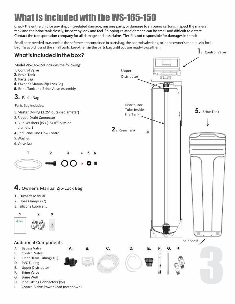
What is included with the WS-165-150 Check the entire unit for any shipping-related damage, missing parts, or damage to shipping cartons. Inspect the mineral tank and the brine tank closely, inspect by look and feel. Shipping-related damage can be small and difficult to detect. Contact the transportation company for all damage and loss claims. Tier1® is not responsible for damages in transit.
Small parts needed to assemble the softener are contained in parts bag, the control valve box, or in the owner's manual zip-lock bag. To avoid loss of the small parts, keep them in the parts bag until you are ready to use them. 1. Control ValveWhat is included in the box? Model WS-165-150 includes the following: 1. Control Valve2. Resin Tank3. Parts Bag4. Owner's Manual Zip-Lock Bag5. Brine Tank and Brine Valve Assembly
3. Parts Bag
Parts Bag includes:
1. Master O-Ring (3.25" outside diameter)2. Ribbed Drain Connector3. Blue Washers (x2) (15/16" outside
diameter)4. Red Brine Line Flow Control5. Washer6. Valve Nut
Upper Distributor
Distributor Tube Inside the Tank
2. Resin Tank
5. Brine Tank
4. Owner's Manual Zip-Lock Bag
1. Owner's Manual2. Hose Clamps (x2)3. Silicone Lubricant
Additional ComponentsA. Bypass ValveB. Control ValveC. Clear Drain Tubing (10')D. PVC TubingE. Upper DistributorF. Brine ValveG. Brine WellH. Pipe Fitting Connectors (x2)I. Control Valve Power Cord (not shown)
Salt Shelf
3H.

Operating Conditions This softening system will operate at maximum efficiency when the following conditions are considered:
Operating Conditions:
Working Conditions Working pressure 21psi to 120psi Water temperature 40 °F - 120 °F (5°C - 50°C)
Working Environment
Environment temperature 40 °F - 120 °F (5°C - 50°C)
Relative humidity ≤ 95%(When temperature is 25°C/77°F
Power source AC100~240V/50~60Hz
Inlet Water Quality
Water turbidity Down-flow Regeneration < 5FTU
Chlorine < 0.1ppm
Iron2+ < 0.3ppm
• All plumbing and electrical work should be performed by an accredited professional to ensure all local, state,and municipal guidelines are met.
• Do not use the control valve with water that is unsafe or of unknown quality.
• Do not use the brine tube, injector body, or other connectors on the valve as a handle to carry the system.
• Ensure there is salt in the brine tank at all times when in use for softening. The brine tank should containclean water softening salt only, at least 99.5% pure. Do not use small grain salt.
• When there is moderate to high turbidity, a filter should be installed before the softening system on the inletside.
• If the water pressure exceeds 80 psi, it is recommended to install a pressure valve. If the water pressure isunder 20 psi, a booster pump must be installed before the water inlet.
4

ASSEMBLY INSTRUCTIONS Locate the following parts:
Brine Tank – inside the brine tank you will find:
A. Bypass ValveB. Control ValveC. Clear Drain Tubing (10')D. PVC TubingE. Upper DistributorF. Brine ValveG. Brine WellH. Pipe Fitting Connectors (x2)I. Control Valve Power Cord (not shown)
Parts Bag includes:
1. Master O-ring (3.25" outside diameter)2. Ribbed Drain Connector3. Blue Washers (x2) (15/16" outside diameter)4. Red Brine Line Flow Control5. Washer6. Valve Nut
Instruction Manual Zip-Lock Bag includes:
1. Owner’s Manual2. Hose Clamp (x2)3. Silicone Lubricant
5
H.

PRIOR TO ASSEMBLY
A. Prior to installation of this water softener, ensure you are aware of local laws and codes regardingthe installation, use, and maintenance of water softeners.
B. Resin Tank - the tank may be shipped with a temporary shipping cap, a master O-Ring, and a pieceof tape covering the riser tube. This is to prevent resin from entering the riser tube duringshipping. The cap, master O-Ring, and tape must be removed and discarded prior to attachingcontrol valve and the upper distributor. (Another master O-ring is supplied.)
C. Unpack the Tier1 WS-165-150 and ensure all listed parts are included. This water softener includesboth regular control valve connections and a bypass valve connection, with components includedfor each method of installation. Following installation, “extra” parts will remain dependent uponwhich method of installation you choose.
D. Turn off the main water line to your home prior to installation.
E. If you will be draining the tank, shut off the power supply to your water heater.
F. Turn on the water faucets in the highest and lowest levels of your home.
Begin assembly as on pages 7-12.
6
IMPORTANT NOTE: To avoid irreversible damage to connector threading, hand tighten plastic connections first. If leaks are noted during initial start up, gently tighten with tool.

ASSEMBLY INSTRUCTIONS STEP 1: Attach the Control Valve to the Resin Tank
A. Locate the Master O-ring (from Parts bag) and lightly coat with silicone lubricant (from Owner’sManual Zip-Lock Bag). Insert into bottom of control valve, as shown below.
B. Connect the upper distributor to bottom of control valve, line up slots and twist, as shown below.
C. Center the riser pipe within the resin tank.D. Attach the control valve to the resin tank by sliding the upper distributor over the riser pipe.E. Securely tighten the control valve by hand, tightening it clockwise.
If you ARE installing the supplied bypass valve, go to step 3.
If you are NOT installing bypass valve, continue to Step 2. Note: You will have extra parts using either method.
Step 2: Connect Control Valve Input and Output Connections with Flow Meter
A. Insert blue washers (from Parts Bag) into input and output connections on the control valve,as shown below.
B. Locate pipe fitting connectors (inside control valve box). Remove the plastic clamps on theconnectors to detach the pipe fitting from the bypass valve connectors.
C. Screw the threaded end of the pipe fittings into the control valve.D. Lightly coat the O-rings on connectors with lubricant before connecting them
into the pipe fittings. 7

ASSEMBLY INSTRUCTIONS E. Insert the connectors into the pipe fittings. The outlet connector containing water meter probe dock
and the impeller must be installed in the outlet side of the bypass valve (as marked). Insert water meter probe in dock.
F. Reinstall the plastic clamps on the connectors.
Proceed to Step 4
Step 3: Assembly using the included bypass valve
A. Insert blue washers (from Parts Bag) into input and output connections on the control valve,as shown below.
B. IMPORTANT: If you are using the bypass valve, the meter impeller must be installed for thebypass valve to function properly. Locate pipe fitting connectors (inside control valve box). Theoutlet connector with water meter probe dock (as shown) contains the meter impeller. Remove the plasticclamp from the outside of the outlet connector, and pull apart the connector to access the impeller inside.Remove the meter impeller. Note: You will not need the connectors for your installation and may discardthem.
C. Remove the plastic clamp from the bypass valve outlet side. Pull out the pipe fitting. Insert themeter impeller into the bypass valve, fan blade side facing down, rotating the meter impeller toensure the grooves of the meter impeller frame align with the grooves inside of the bypass valveoutlet as shown below. Insert pipe fitting into bypass valve. Replace plastic clamp.
8

ASSEMBLY INSTRUCTIONS D. To attach the bypass valve onto the control valve, remove plastic clamps from both inlet and outlet of
bypass valve. Remove pipe fitting ends from bypass outlets and thread onto control valve. Connectbypass valve onto fittings and reinstall plastic clamps.
E. Insert water meter probe from control valve into the bypass valve’s on-board water meter probe dock,ensuring it is securely seated, as shown below.
Step 4: Connect the brine line to the brine tank
A. Remove brine well cap from brine well, as shown below.
9

ASSEMBLY INSTRUCTIONS
Figure 1.1
B. Unscrew connecting nut (1) from brine valve (2) attached to brine tubing as shown in Figure 1.1.C. Verify the plastic sleeve is inserted completely into the end of the brine tube as shown below.
D. If necessary adjust position of connecting nut on brine tubing to allow threads to engage completelywith brine valve.
E. While pushing brine valve threads through hole in brine well, push brine tubing with connecting nutfirmly into brine valve.
10 F. Tighten connecting nut outside of brine well. If necessary, adjust position of connecting nut on
brine tubing to ensure threads are screwed on tightly.G. Feed other end of tubing through hole (3) in brine tank. Be sure not to loosen or kink tubing.H. Replace brine well cap.I. Follow steps on next page to connect brine tubing to control valve.

ASSEMBLY INSTRUCTIONS J. Insert the red brine line flow control (from Parts bag) with the cone side facing into control valve, into the
control valve brine line connector.
K. Insert brine line into control valve. Tighten the nut onto the brine line connection, as shown in the areaof magnification below.
11

ASSEMBLY INSTRUCTIONS STEP 6: Connect the backwash hose to the control valve
A. Insert washer (from Parts bag) into ribbed drain connector.
B. Thread ribbed drain connector (from Parts bag), onto drain connection.C. Attach clear drain tubing to connector. Secure using a hose clamp (from Owner’s Manual Zip-Lock bag).D. Secure the clear drain tubing over a floor drain or other suitable drain.E. Leave an air gap of about 1 ½” between the end of the hose and the drain. This air gap is necessary to
ensure there will be no back flow of sewer water into the water softener.
STEP 7: Connect control valve input to home water supply.
STEP 8: Connect control valve output to home plumbing.
STEP 9: Flush out water lines and program control valve as on following pages, before first use.
12

FLUSHING THE WATERLINES Before operating water softener for the first time, flush out your water lines and the water softener bypass.
• Check that bypass is closed. Knob on top of inlet should be turned to "By-Pass" (side opposite of "In-Serv")
• Turn the water source on at the inlet to your home.
• Disconnect the bypass from the control valve by removing plastic clamps and pulling bypass out of fitting.
• Remove the meter impeller from the bypass by tilting bypass downward until it drops out. Reconnect bypass.• Place a container under the bypass to collect water. Open the bypass by turning knob on top of the inlet to “In-
Serv. Allow water to flow through to flush out any foreign material from the water lines.• Close the bypass by turning the knob on top of inlet back to "By-Pass".
• Reinstall the meter impeller in the outlet as on page 8. Reconnect bypass to the valve and reinstall plastic clamps.
• Open the bypass by turning knob on top of the inlet to “In-Serv”.
• Check for any water leaks.
• Insert the water meter probe into water meter probe dock on the outlet side of the bypass (as on page 9).
SYSTEM STARTUP AND PROGRAMMING • Attach the power cord to the control valve, and plug in the control valve power cord.
• Open a water line and let water flow until water runs clear.
• Using a pail or pitcher, fill brine tank about 1/3 full with water.
Programming instructions begin on next page.
The factory default settings are on page 15, followed by step by step programming instructions on page 16-17.
A programming key is available on page 19 detailing all button settings.
Please review all settings and adjust as necessary for your water hardness to ensure that the water softener will work most effectively for your needs.
13
MASTER PROGRAMMING
14
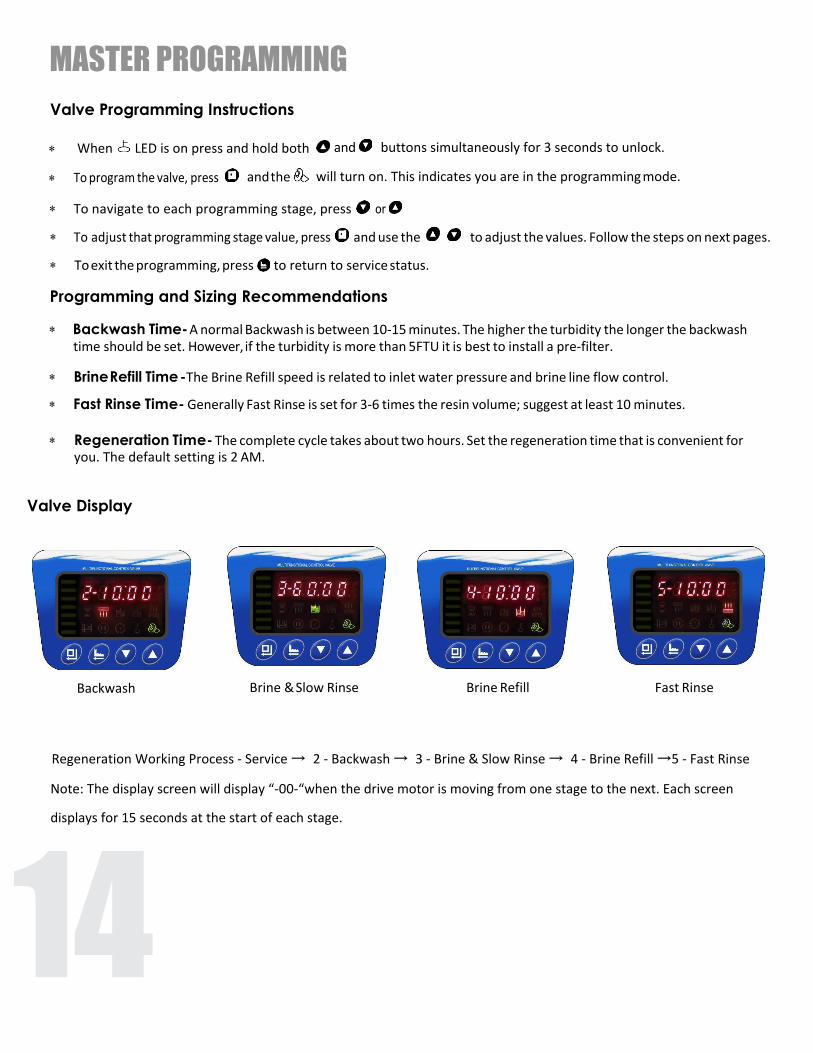
Valve Programming Instructions
∗ When LED is on press and hold both
∗ To program the valve, press and the
and buttons simultaneously for 3 seconds to unlock.
will turn on. This indicates you are in the programming mode.
∗ To navigate to each programming stage, press or
∗ To adjust that programming stage value, press and use the to adjust the values. Follow the steps on next pages.
∗ To exit the programming, press to return to service status.
Programming and Sizing Recommendations
∗ Backwash Time- A normal Backwash is between 10-15 minutes. The higher the turbidity the longer the backwash time should be set. However, if the turbidity is more than 5FTU it is best to install a pre-filter.
∗ Brine Refill Time -The Brine Refill speed is related to inlet water pressure and brine line flow control.
∗ Fast Rinse Time- Generally Fast Rinse is set for 3-6 times the resin volume; suggest at least 10 minutes.
∗ Regeneration Time- The complete cycle takes about two hours. Set the regeneration time that is convenient for you. The default setting is 2 AM.
Valve Display
Backwash Brine & Slow Rinse Brine Refill Fast Rinse
Regeneration Working Process - Service → 2 - Backwash → 3 - Brine & Slow Rinse → 4 - Brine Refill →5 - Fast Rinse
Note: The display screen will display “-00-“when the drive motor is moving from one stage to the next. Each screen
displays for 15 seconds at the start of each stage.

FACTORY DEFAULT SETTINGS Function Indicator Factory Default Parameter Set Range Instruction
Time of Day Random 00:00~23:59 Set the current time of day while the “:” flashes.
Control Mode A-01 A-01
A-01Meter Delayed. Regeneration occurs at the set regeneration time once the gallons used reaches zero (0).
A-02Meter Immediate. Regeneration occurs immediately once the gallons used reaches zero (0).
Unit Mode HU-02 HU-02 01, 02, 03 01-m3; 02-gal; 03-L
Regeneration Time 02:00 02:00 00:00~23:59 Regeneration time. “:” light on
Water Treatment Capacity
2500 0-10,000
To figure capacity, multiply the total resin volume multiplied by .75. Divide by grains of hardness of water supply.
Example: 1.5 Cu/Ft = 48,000 x .75 at 15 grains hardness. (48,000 x .75) ÷ 15= 2400 gallons.
Backwash Time 10 min. 0~99∶59 Backwash Time.
Brine & Slow Rinse Time
60 min. 0~99∶59 Brine & Slow Rinse Time.
Brine Refill Time 5 min. 0~99∶59 Refill Time is calculated based on total resin volume. Note: 1 gal water dissolves 3lbs of salt.
Fast Rinse Time 10 min. 0~99∶59 Fast Rinse Time.
Maximum Interval Regeneration Days H-30 30 0~40
Forced regeneration every 30 days if no water has been used. Time Clock Valve: to operate as a time clock valve, set the number of days before desired regeneration.
Output Control Mode
b-01 01 01 or 02
b-01: Signal turns on at start of regeneration and shuts off atend of regeneration.
b- 02: Signal available in intervals during regeneration cycles andduring In Service.
15

MASTER PROGRAMMING
16
Step by Step Programming Instructions
Items Process steps Screen Display
Time of Day
Note: when “12:12” flashes; Time of Day needs to be reset.
1. Press to set Time of Day; both and will light and the “:” symbol will flash.
2. Press , both and “H" value will flash, press or to adjust hour value.
3. Press , both and “M” value will flash, press or to adjust minute value.
4. Press to accept adjustments made. Press to advance to the next programming phase.
Control Mode
1. Press
2. Press
3. Press
to enter Control Mode, and “01” value will flash.
or buttons to choose A-01 or A-02. Note: A-03 and A-04 not available in U.S. to accept adjustments made. Press to advance to the next programming phase.
Unit Mode 1. Press
2. Press
3. Press
to enter Unit Mode, and “02”value will flash.
or to choose HU-1 (m3), HU-2 (gal) or HU-03(L).
to accept adjustments made. Press to advance to the next programming phase.
Regeneration Time
Note: No regeneration time called for in A-02 Control Mode. 1. Press to enter Regeneration Time, and “Hour” value will flash. 2. Press or
3. Press again,
to adjust the hour value to the desired regeneration time. (24 hour clock)
and “Minute” value will flash, press or to adjust minute value. 4. Press to accept adjustments made. Press to advance to the next programming phase.
Water Treatment Capacity
1. Press
2. Press
3. Press
to enter Capacity; gal, and along with the “2500” value will flash.
or to adjust water treatment capacity value (gal orm3). to accept adjustments made. Press to advance to the next programming phase.
Backwash Time
1. Press
2. Press3. Press
along with “2-10:00” value will flash.to enter Backwash Time; and or to adjust the backwash time. to accept adjustments made. Press to advance to the next programming phase.
Brine & Slow Rinse Time
1. Press
2. Press
3. Press
to enter Brine & Slow Rinse Time, and along with “3-60:00” value will flash. or to adjust the brine time.
to accept adjustments made. Press to advance to the next programming phase.
Brine Refill Time
Note: See instructions below to determine brine refill time needed for your size system.
1. Press to enter Brine Refill Time, and along with “4-5:00” value will flash.
2. Press or to adjust the brine refill time. 3. Press to accept adjustments made. Press to advance to the next programming phase.
Calculating Brine Refill Time - The brine refill time is calculated based on total resin volume. For optimal efficiency, 5 gallons should be used for 10x54 (48,0000) grain systems.

MASTER PROGRAMMING Step by Step Programming Instructions Continued
Fast Rinse Time
1. Press
2. Press
3. Press
to enter FastRinse Time, and along with “5-10:00”value will flash.
or to adjust the fast rinse time. to accept adjustments made. Press to advance to the next programming phase.
Maximum Regeneration Days
1. Press
2. Press
3. Press
to enter Maximum Interval Regeneration Days, and “H-30” value will flash.
or to adjust the interval regeneration days.
to accept adjustments made. Press to advance to the next programming phase.
Signal Output Mode
1. Press
2. Press
3. Press
to enter Signal Output Mode, and “b-01” value will flash. or
to adjust the signal output mode value.
to accept adjustments made. Press and return to service status.
After control valve has been programmed, perform the following steps before first use:
• Press and hold both and buttons simultaneously for 3 seconds to unlock the keypad.
• Press to advance to 2-Backwash; this lets air out of the drain line. Process will take 8-10 minutes to purge thesystem.Note: When you press the screen will display "-00-" as it positions the ceramic discs. Once "-00-" disappears andthe next phase is displayed, you can press to advance to the next phase.
• Press to manually advance through the next phase, 3-Brine & Slow Rinse. Verify the air check valve is closed by listening to be sure no air is being drawn into the system.
• Press to manually advance to the next phase, 4-Brine Refill. This stage will fill the brine tank with the correct amount of water. Allow the brine refill phase to run, do not advance past this phase. It should take about 15 minutes for a 1.5 cu/ft system. After this phase has completed, press to manually advance to 5-Fast Rinse, and again to advance to the Service position.
• Next add salt to the brine tank. (40 lb minimum, 120 lb maximum)Note: We recommend using water softener salt.
• Install brine tank cover.• Turn a faucet on, away from the installation location, until the water from the plumbing lines has been purged.
• Your water softener should now be fully operational.
• To verify that your water softener is functioning correctly, you can take a water sample testto verify hardness reduction.
• Tier1 recommends the Water Total Hardness Test (3-pack) by Tier 1. Purchase the test atwww.tier1filters.com/harness-test or by calling 1-855-378-9116. 17

CARE AND MAINTENANCE
BRIDGING Humidity or the wrong type of salt may create a cavity between the water and the salt. This action, known as “bridging”, prevents the brine solution from being made, preventing the water softener from working.
If you suspect salt bridging, carefully pound on the outside of the plastic brine tank, or pour some warm water over the salt to break up the bridge. This should always be followed by allowing the unit to use up any remaining salt, and then thoroughly cleaning out the brine tank. Allow four hours to produce a brine solution, then manually regenerate the softener.
CAUTION Liquid brine will irritate eyes, skin, and open wounds. Gently wash exposed areas with fresh water. Keep children away from water softener.
PRODUCT CARE To retain the attractive appearance of your new softener, clean occasionally with a mild soap solution. Do not use abrasive cleaners, ammonia, or solvents. Never subject your softener to freezing or to temperatures above 43 degrees Celsius (110 degrees Fahrenheit).
18

PROGRAMMING KEY AND GENERAL INFORMATION
*
19
Programming Key
Time of Day Indicator
LED on, displays the time of day. LED flashes, need to reset time of day after electrical service has been interrupted for 3 days or more.
Button Lock Indicator LED on, indicates the buttons are locked.
* To unlock, press and hold both and buttons for 3 seconds until the Program Mode Indicator
LED turns off.
∗ LED on, enter program display mode. Use or buttons to view all values. ∗ LED flashes, enter program set mode. Press or buttons to adjust values.
Menu/Confirm Button* Press , the LED turns on; enter program display mode, press or to view all values.
* In program display mode, press the* Press after all program features are set.
Manual /Return Button
LED flashes; enter program set mode and press or to adjust values.
* Press the button to proceed to the next step. (Ex: Press the button while the valve is in Service status and it will start a manual regeneration. Press again and the valve will go to Brine & Slow Rinse instantly.)
* Press the * Press the * Press the
button in program display mode and it will return to In Service. button in program set mode and i t will return to program display mode. while adjusting the value and it will return to program display mode directly without saving value.
* Press and hold both and simultaneously for 3 seconds to unlock the program functions.
to adjust values. * In program display mode press or to view all values.
Down and Up Buttons
* A flashing dynamic display stripe indicates the water softener is in service.A steady dynamic display stripe indicates the water softener is in the regeneration cycle
* In program set mode press or

WS-165-150 SeriesWater Softener
Tier1®is a registered trademark of US Water Filters, Inc.Zumbrota, Minnesota
Copyright©2019 US Water Filters, Inc. All rights reserved.
Tier1®
www.Tier1water.com
1-855-378-9116Version 191101