165-e06
TRANSCRIPT
2012 VOL. 58 NO.165 Introduction of Hydrostatic Transmission Forklift Model FH40-1/FH45-1/FH50-1
― 1 ―
Introduction of Products
Introduction of Hydrostatic Transmission Forklift Model
FH40-1/FH45-1/FH50-1
Hiroyuki Yamamoto
Yasuo Harada
Hideyuki Hiraiwa
The 4-ton class engine powered forklift truck, FH series FH40/45/50-1, have been developed and introduced
into the market as Komatsu’s first forklift truck installed electronic controlled HST (Hydrostatic Transmission)
and variable pump CLSS (closed-center load sensing system). New technologies and outline of the improvement
for fuel efficiency in the new models are introduced.
Key Words: Forklift, HST, Hydrostatic Transmission, CLSS, Closed Center Load Sensing System, Low Fuel
Consumption, Environment, Safety, ICT
1. Introduction
In recent years, needs for low fuel consumption and
reduction in environmental loads have rapidly increased in
industrial vehicles and construction machinery due to growing
global environmental awareness and a rise in crude oil prices.
The response to the above has become an important element
in the development and manufacturing of forklifts.
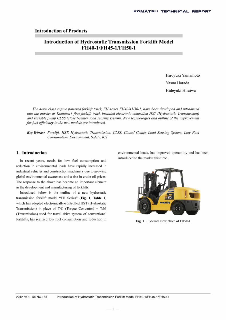
Introduced below is the outline of a new hydrostatic
transmission forklift model “FH Series” (Fig. 1, Table 1)
which has adopted electronically-controlled HST (Hydrostatic
Transmission) in place of T/C (Torque Converter) + T/M
(Transmission) used for travel drive system of conventional
forklifts, has realized low fuel consumption and reduction in
environmental loads, has improved operability and has been
introduced to the market this time.
Fig. 1 External view photo of FH50-1
2012 VOL. 58 NO.165 Introduction of Hydrostatic Transmission Forklift Model FH40-1/FH45-1/FH50-1
― 2 ―
Table 1 Major Specifications
Item Unit Developed
model FH50-1
Current model
FD50AT-10
Performance and dimensions
Maximum load kg 5000 5000
Load center mm 600 600
Maximum travel speed km/h 23. 5 25
Wheelbase mm 2000 2000
Tread Front/Rear mm 1225/1120 1150/1120
Machine mass kg 7380 7295
Engine
Manufacturer - Komatsu Komatsu
Model name - SAA4D95LE SAA4D95LE
No. of cylinders / Total displacement -/cc 4/3260 4/3260
Rated output kW/rpm 50.8/2150 59.7/2400
Fuel tank capacity L 105 98
Information ICT - KOMTRAX -
2. Development Objectives and Means of
Achievement
(1) Reduction in fuel consumption
Reduction in power transmission loss thanks to the
electronically-controlled HST
Realization of low fuel consumption in high load work by
controlling engine output in accordance with cargo weight
Reduction in oil pressure loss during simultaneous
operation of load handling system and travel drive system
thanks to CLSS + variable pump
(2) Improvement in operability and workability
Travel operation has become easier than that of T/C
forklifts due to the adoption of electronically-controlled HST.
Improvement in workability during stopping, hill starting
and switch-back operation
(3) Improvement in safety
Travel speed limiting function as standard equipment
(4) ICT
Installation of “KOMTRAX” as standard for the first time
in forklifts
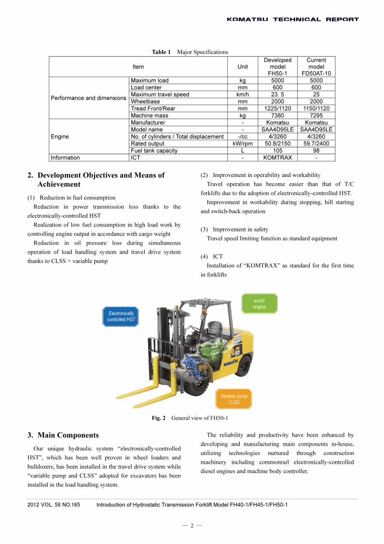
Fig. 2 General view of FH50-1
3. Main Components
Our unique hydraulic system “electronically-controlled
HST”, which has been well proven in wheel loaders and
bulldozers, has been installed in the travel drive system while
“variable pump and CLSS” adopted for excavators has been
installed in the load handling system.
The reliability and productivity have been enhanced by
developing and manufacturing main components in-house,
utilizing technologies nurtured through construction
machinery including commonrail electronically-controlled
diesel engines and machine body controller.
Electronically
controlled HST
ecot3
engine
Variable pump
CLSS
2012 VOL. 58 NO.165 Introduction of Hydrostatic Transmission Forklift Model FH40-1/FH45-1/FH50-1
― 3 ―
Fig. 3 Main components
4. Outline of System
4.1 Conventional forklift (with torque
converter)
The structure of a general, conventional T/C forklift is
shown in Fig. 4.
The clutch is attached to the output shaft of the
transmission and when the inching pedal is depressed, power
is shut off. If you want to travel forward slowly while
operating the load handling system fast (simultaneous
operation of load handling and travel), depress the accelerator
pedal to increase engine speed and adjust clutch slip with the
inching pedal to control the travel speed.
Fig. 4 System structure chart of general conventional forklift (T/C forklift)
In general, a gear pump is used for the hydraulic system of
the load handling system, and because it is a fixed capacity
type pump, a constant oil quantity is supplied according to
engine speed regardless of the operation of load handling
system.
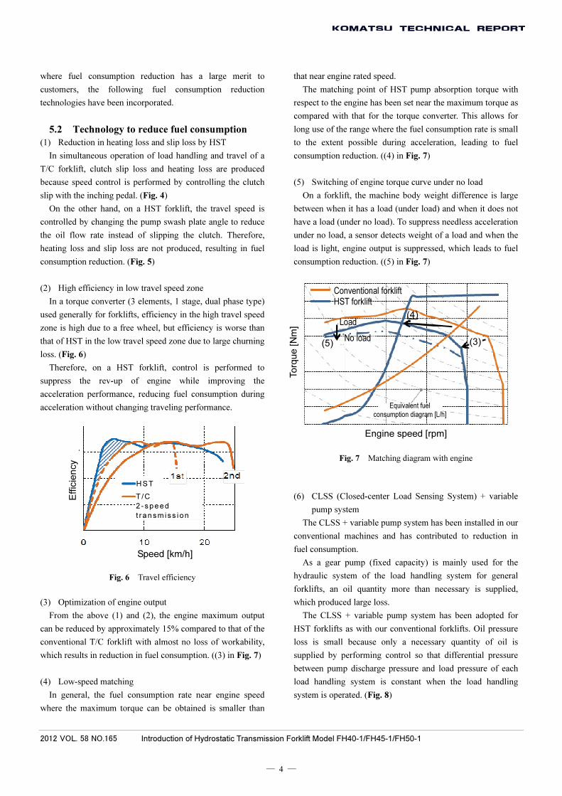
4.2 New FH Series forklift (with HST)
The system structure of the new “FH Series” HST forklift
is shown in Fig. 5.
The engine rotates the pump to produce oil pressure, which
is converted again to turning force with the motor. A flow rate
of hydraulic oil is continuously increased or decreased by
changing the angle of the swash plate connected to the pistons
to change the piston stroke. This swash plate angle control
realizes the stepless speed control from forward travel, stop to
reversing. When the swash plate is moved to the neutral
position, the piston stroke stops, producing the same effect as
the application of the brake.
When the inching pedal is depressed, the HST pump swash
plate moves to the neutral position and the machine stops.
During simultaneous operation of load handling and travel,
depress the accelerator pedal to increase engine speed, change
a HST pump capacity control signal from the controller with
the inching pedal and adjust the swash plate angle (oil
quantity) to control the travel speed.
A variable pump is used also for the hydraulic system of
load handling system and supplies only a necessary quantity
of oil with a signal from the operating valve.
Fig. 5 System structure chart of HST forklift
5. Reduced Fuel Consumption
5.1 Usage of forklift
Forklifts are often operated in a limited place, and
acceleration and stop (with change in travel direction, forward
and backward), and simultaneous operation of load handling
and travel are frequently performed. This type of usage is
more remarkable in a worksite with higher load and higher
rate of operation. As such condition also makes the fuel
consumption larger, users have a keen interest in fuel
consumption reduction. In consideration of such worksites
Variable pump for load handling
system
Commonrail electronically-
controlled engine
HST hydraulic
pump
HST hydraulic
motor
Inching
pedal Conventional forklift (T/C forklift) Accelerator
pedal
Transmission
Torque converter
Diffe
r-
ential
Clutch
Engine
Tire Operating
lever
Gear pump
HST forklift Inching
pedal Accelerator
pedal
Motor Pump
Swash plate
Controller
Engine
Tire
Pressure sensor
Operating lever
Operating valve
Variable pump
Load handling system
Load handling system
Diffe
r-
ential
Operating valve
2012 VOL. 58 NO.165 Introduction of Hydrostatic Transmission Forklift Model FH40-1/FH45-1/FH50-1
― 4 ―
where fuel consumption reduction has a large merit to
customers, the following fuel consumption reduction
technologies have been incorporated.
5.2 Technology to reduce fuel consumption
(1) Reduction in heating loss and slip loss by HST
In simultaneous operation of load handling and travel of a
T/C forklift, clutch slip loss and heating loss are produced
because speed control is performed by controlling the clutch
slip with the inching pedal. (Fig. 4)
On the other hand, on a HST forklift, the travel speed is
controlled by changing the pump swash plate angle to reduce
the oil flow rate instead of slipping the clutch. Therefore,
heating loss and slip loss are not produced, resulting in fuel
consumption reduction. (Fig. 5)
(2) High efficiency in low travel speed zone
In a torque converter (3 elements, 1 stage, dual phase type)
used generally for forklifts, efficiency in the high travel speed
zone is high due to a free wheel, but efficiency is worse than
that of HST in the low travel speed zone due to large churning
loss. (Fig. 6)
Therefore, on a HST forklift, control is performed to
suppress the rev-up of engine while improving the
acceleration performance, reducing fuel consumption during
acceleration without changing traveling performance.
Fig. 6 Travel efficiency
(3) Optimization of engine output
From the above (1) and (2), the engine maximum output
can be reduced by approximately 15% compared to that of the
conventional T/C forklift with almost no loss of workability,
which results in reduction in fuel consumption. ((3) in Fig. 7)
(4) Low-speed matching
In general, the fuel consumption rate near engine speed
where the maximum torque can be obtained is smaller than
that near engine rated speed.
The matching point of HST pump absorption torque with
respect to the engine has been set near the maximum torque as
compared with that for the torque converter. This allows for
long use of the range where the fuel consumption rate is small
to the extent possible during acceleration, leading to fuel
consumption reduction. ((4) in Fig. 7)
(5) Switching of engine torque curve under no load
On a forklift, the machine body weight difference is large
between when it has a load (under load) and when it does not
have a load (under no load). To suppress needless acceleration
under no load, a sensor detects weight of a load and when the
load is light, engine output is suppressed, which leads to fuel
consumption reduction. ((5) in Fig. 7)
Engine speed [rpm]
Fig. 7 Matching diagram with engine
(6) CLSS (Closed-center Load Sensing System) + variable
pump system
The CLSS + variable pump system has been installed in our
conventional machines and has contributed to reduction in
fuel consumption.
As a gear pump (fixed capacity) is mainly used for the
hydraulic system of the load handling system for general
forklifts, an oil quantity more than necessary is supplied,
which produced large loss.
The CLSS + variable pump system has been adopted for
HST forklifts as with our conventional forklifts. Oil pressure
loss is small because only a necessary quantity of oil is
supplied by performing control so that differential pressure
between pump discharge pressure and load pressure of each
load handling system is constant when the load handling
system is operated. (Fig. 8)
Speed [km/h]
Effic
ien
cy
To
rqu
e [N
m]
Conventional forklift HST forklift
Load
No load(5)
(4)
(3)
Equivalent fuel
consumption diagram [L/h]
T/C
2 -speed
t ransmiss ion
HST

2012 VOL. 58 NO.165 Introduction of Hydrostatic Transmission Forklift Model FH40-1/FH45-1/FH50-1
― 5 ―
Fig. 8 Reduction effect of oil pressure loss of load handling system
6. Result
6.1 Reduction in fuel consumption
Fig. 9 shows the fuel consumption reduction effect at
in-house measurement courses.
The fuel reduction effect was obtained in any course. In
particular, the effect of no less than 29% was obtained at a
high load course (Course A) where there is a lot of switch
back in a short distance assuming loading work to a truck.
Fig. 11 shows the frequency distribution of engine speed
and torque at the high load course (Course A). This shows that
as a circle is larger, the frequency is higher. It can be seen that
large circles move to the small fuel consumption side as
compared with those for the conventional forklift. In
particular, HST forklift used the range where there was little
change in engine speed during acceleration and fuel
consumption was small for a long time. Therefore, the result
as intended was obtained.
Fig. 9 Result of fuel consumption reduction at in-house courses
According to high load user data at a paper mill where HST
forklifts were introduced on a trial basis, a maximum of 30%
fuel consumption reduction compared to our conventional
forklifts was accomplished. (Fig. 10)
Fig. 10 Result of fuel consumption reduction at user's worksites
Fig. 11 Frequency distribution and fuel consumption map at high load course
Loss during relief Loss in neutral Loss during fine control
Circ
uit u
sing
fixe
d
pum
p
Discharge of total quantity Discharge of total quantity Discharge of total quantity
Circ
uit u
sing
var
iabl
e
pum
p C
LSS
Required flow rate Required flow rate Required flow rate
Red
uctio
n ef
fect
of
oil p
ress
ure
loss
Flow rate Reduction loss
Flow rate Reduction loss
Flow rate Reduction loss
Pump pressure Pump pressure
Va
riab
le p
ump
Va
riab
le p
ump V
aria
ble
pum
p
Fix
ed
pum
p
Fix
ed
pum
p
Fix
ed
pum
p
Fue
l con
sum
ptio
n [L
/h]
Test course High load Low load
Conventional forklift
HST forklift
Course A Course B Course C
Fue
l con
sum
ptio
n [L
/h]
High load user Paper mill
Medium load user
Conventional forklift
HST forklift
Engin
e t
orq
ue
Engine speed [rpm]
Conventional forklift
HST forklift
Equivalent fuel
consumption diagram [L/h]
Lever input

2012 VOL. 58 NO.165 Introduction of Hydrostatic Transmission Forklift Model FH40-1/FH45-1/FH50-1
― 6 ―
Type of business in which HST forklift is effective for decreasing fuel consumption (Fig. 12)
Handling business of recycled resources (wastepaper)
Bale clamp
Handling business of timber and woodwork
Hinged fork
Handling business of recycled resources (general)
Hinged bucket
Handling business of concrete secondary product
Hinged fork
Fig. 12 Example of type of business where forklifts are used
6.2 Improvement in operability and
workability
On the electronically-controlled HST, the swash plate is
controlled continuously at the time of change between
forward travel and backward travel so that the change can be
performed without a shock without stopping once and with
the accelerator pedal kept depressed. Thus, the brake
operation like conventional forklifts is not required.
In addition, the braking by setting the swash plate in the
neutral position, a characteristic of HST, reduces rolling down
of the machine on a slope, contributing to the reduction of
fatigue of an operator.
6.3 Safety
The travel speed limiting function is equipped as standard.
The maximum speed can be set to four stages with respect to
the speed control in a limited space, speed limit specified in a
plant, and so on.
6.4 ICT (Information and Communication
Technology)
The machine remote monitoring system “KOMTRAX” has
been installed as standard in forklifts for the first time.
“Visualization” of machine information such as the location,
operating condition and fuel consumption has allowed to
support the fleet management with meticulous attention.
7. Conclusion
In cooperation with Power Train Development Center and
Hydraulic Equipment Technical Center, we have realized
commercialization of forklifts installed with electronically-
controlled HST and CLSS hydraulic system for the first time
as Komatsu.
We will continue to make efforts to expand the model
lineup installed with HST and CLSS in the future and at the
same time to aim at further technological leaps to develop
these models to be more attractive to customers.

2012 VOL. 58 NO.165 Introduction of Hydrostatic Transmission Forklift Model FH40-1/FH45-1/FH50-1
― 7 ―
Introduction of the writers
Hiroyuki Yamamoto
Entered Komatsu Ltd. in 1981.
Currently assigned to Technical Center,
Utility Equipment Division
Yasuo Harada
Entered Komatsu Ltd. in 1975.
Currently assigned to Technical Center,
Utility Equipment Division
Hideyuki Hiraiwa
Entered Komatsu Ltd. in 1992.
Currently assigned to Technical Center,
Utility Equipment Division
[A few words from writers]
We think we have completed the competitive forklifts by
concentrating the Komatsu technologies thanks to the merger of
the utility equipment businesses in 2011.
We would like to express our deep gratitude to IPA,Hydraulic
Equipment Technical Center,Power Train Development Center,
System Development Center,Test Engineering Center, and
Tochigi Plant and other production departments, not to mention
the customers and distributors who helped our researches.