16th iccrts “collective c2 in multinational civil … · “collective c2 in multinational...
TRANSCRIPT

16th ICCRTS
“Collective C2 in Multinational Civil-Military Oper ations”
High-level Closed-loop Fusion and Decision Making with INFORM lab
Topic 8: Architectures, Technologies, and Tools
Name of Author(s)
Adel Guitouni, Pierre Valin R & D Defence Canada - Valcartier
2459 Pie XI North Quebec, QC Canada, G3J 1X5
Hans Wehn, Jens Happe
MacDonald, Dettwiler and Associates (MDA) 13800 Commerce Parkway
Richmond, BC Canada, V6V 2J3
Point of Contact
Hans Wehn MacDonald, Dettwiler and Associates (MDA)
13800 Commerce Parkway Richmond, BC Canada, V6V 2J3 e-mail: [email protected]
Report Documentation Page Form ApprovedOMB No. 0704-0188
Public reporting burden for the collection of information is estimated to average 1 hour per response, including the time for reviewing instructions, searching existing data sources, gathering andmaintaining the data needed, and completing and reviewing the collection of information. Send comments regarding this burden estimate or any other aspect of this collection of information,including suggestions for reducing this burden, to Washington Headquarters Services, Directorate for Information Operations and Reports, 1215 Jefferson Davis Highway, Suite 1204, ArlingtonVA 22202-4302. Respondents should be aware that notwithstanding any other provision of law, no person shall be subject to a penalty for failing to comply with a collection of information if itdoes not display a currently valid OMB control number.
1. REPORT DATE JUN 2011 2. REPORT TYPE
3. DATES COVERED 00-00-2011 to 00-00-2011
4. TITLE AND SUBTITLE High-level Closed-loop Fusion and Decision Making with INFORM lab
5a. CONTRACT NUMBER
5b. GRANT NUMBER
5c. PROGRAM ELEMENT NUMBER
6. AUTHOR(S) 5d. PROJECT NUMBER
5e. TASK NUMBER
5f. WORK UNIT NUMBER
7. PERFORMING ORGANIZATION NAME(S) AND ADDRESS(ES) Defence R&D Canada - Valcartier,2459 Pie XI North,Quebec, QCCanada, G3J 1X5,
8. PERFORMING ORGANIZATIONREPORT NUMBER
9. SPONSORING/MONITORING AGENCY NAME(S) AND ADDRESS(ES) 10. SPONSOR/MONITOR’S ACRONYM(S)
11. SPONSOR/MONITOR’S REPORT NUMBER(S)
12. DISTRIBUTION/AVAILABILITY STATEMENT Approved for public release; distribution unlimited
13. SUPPLEMENTARY NOTES Presented at the 16th International Command and Control Research and Technology Symposium(ICCRTS 2011), Qu?c City, Qu?c, Canada, June 21-23, 2011. U.S. Government or Federal Rights License
14. ABSTRACT The INFORM Lab testbed allows experimenting with high-level distributed information fusion dynamicresource management and configuration management, given multiple constraints on the resources andtheir communications networks. The paper describes the architecture, the concepts of goals and situationevidence, algorithms for distributed information and dynamic resource management, andauto-configurable information fusion architectures. The testbed provides general services which include amulti-layer plug-and-play architecture, and a general multi-agent framework based on John Boyd’sOODA loop. The testbed?s performance is demonstrated on scenarios/vignettes for 2 types of Coastal WideArea Surveillance scenarios/vignettes: a cooperative search-and-rescue effort and a non-cooperativesmuggling scenario. INFORM Lab’s usefulness as a research and teaching tool are also discussed.
15. SUBJECT TERMS
16. SECURITY CLASSIFICATION OF: 17. LIMITATION OF ABSTRACT Same as
Report (SAR)
18. NUMBEROF PAGES
48
19a. NAME OFRESPONSIBLE PERSON
a. REPORT unclassified
b. ABSTRACT unclassified
c. THIS PAGE unclassified
Standard Form 298 (Rev. 8-98) Prescribed by ANSI Std Z39-18

Abstract
The INFORM Lab testbed allows experimenting with high-level distributed information fusion, dynamic resource management and configuration management, given multiple constraints on the resources and their communications networks. The paper describes the architecture, the concepts of goals and situation evidence, algorithms for distributed information and dynamic resource management, and auto-configurable information fusion architectures. The testbed provides general services which include a multi-layer plug-and-play architecture, and a general multi-agent framework based on John Boyd's OODA loop. The testbed’s performance is demonstrated on scenarios/vignettes for 2 types of Coastal Wide Area Surveillance scenarios/vignettes: a cooperative search-and-rescue effort and a non-cooperative smuggling scenario. INFORM Lab's usefulness as a research and teaching tool are also discussed.
1 Introduction
The large volume surveillance problem faced by Canada is characterized by the employment of mobile (maritime patrol aircraft, helicopters, UAVs, ships) and fixed surveillance assets (e.g. land radar) to a large geographic area in order to identify, assess and track the maximum number of moving, stopped or drifting objects. The observed objects are not necessarily aware of being observed and are cooperative or non-cooperative, and friendly or hostile. Coastal and Arctic Wide Area surveillance are good examples of large volume surveillance. The scarce surveillance (e.g. Electro-Optical (EO), Infra-Red (IR), and Synthetic Aperture Radar (SAR) sensors) and tracking capabilities (normal radar modes) make it very difficult to perform large volume surveillance and to keep track of all activities. The best strategy for information communication, fusion, resource management and scheduling in such dynamically changing environments is poorly understood. Traditional methods in AI and Mathematical Programming assume a static and non-distributed problem. Unfortunately, often neither assumption is valid. The resource-scheduling problem is dynamically changing as the environment and requirements change due to continuing information updates. Moreover, not all information is always available to all parts of the network. There are communication and computing delays, bandwidth constraints, and communication losses to consider. With multiple surveillance platforms there is a need to network them, and keep each current on the evolving situation. Initial resource deployment starts a dynamically improving awareness picture of the current situation. Ancillary information will continually be supplied from external sources and contribute to the evolution of the situation assessment. This paper provides:
• a description of the architecture of the Information Fusion and Resource Management (INFORM Lab) testbed (section 2),
• the important concepts of goals and situation evidence (section 3), • distributed information fusion (section 4), • dynamic resource management (section 5), • auto-configurable information fusion architectures (section 6), • vignettes (section 7) with results, • future work (section 8), and • conclusions (section 9).
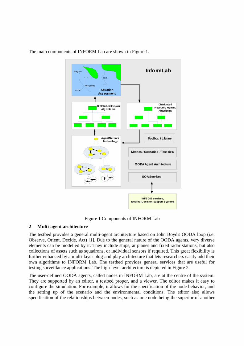
The main components of INFORM Lab are shown in Figure 1.
Figure 1 Components of INFORM Lab
2 Multi-agent architecture
The testbed provides a general multi-agent architecture based on John Boyd's OODA loop (i.e. Observe, Orient, Decide, Act) [1]. Due to the general nature of the OODA agents, very diverse elements can be modelled by it. They include ships, airplanes and fixed radar stations, but also collections of assets such as squadrons, or individual sensors if required. This great flexibility is further enhanced by a multi-layer plug-and play architecture that lets researchers easily add their own algorithms to INFORM Lab. The testbed provides general services that are useful for testing surveillance applications. The high-level architecture is depicted in Figure 2.
The user-defined OODA agents, called nodes in INFORM Lab, are at the centre of the system. They are supported by an editor, a testbed proper, and a viewer. The editor makes it easy to configure the simulation. For example, it allows for the specification of the node behavior, and the setting up of the scenario and the environmental conditions. The editor also allows specification of the relationships between nodes, such as one node being the superior of another
InformLabtra ck
Distributed Fusio nAlg orith ms
Agent Network Technology
Situation Assessment
Distributed Resource Mgmnt.
Algorith ms
SOA Services
WFS GIS services, External Decision Support Systems
Metrics / Scenarios / Test data
OODA Agent Architecture
smug gling
fr eighte r
zodiac
Toolbox / Library

node. The output of the editor is an XML file that contains all the information needed to run the simulation. This configuration file is passed to the testbed, which then runs the simulation. The testbed also provides convenient services to the nodes. For example, the testbed maintains the simulation time, and other global run-time information and metrics, which can be accessed by the nodes via a convenient API. The output of the testbed is a log file, again in XML format, that can be passed on to a Viewer. The viewer allows visualization of the movements of the nodes as a function of time. It also shows the nodes against a GIS background and
environmental factors such as developing fog banks.
Figure 2 High-Level Testbed Architecture
Externally, nodes are characterized by their ability to communicate with other nodes by sending messages via a simulated communication network. For realism, the communication links can be given the characteristics of known standards such as Link-11 or Radio. In INFORM Lab, the nodes usually exchange messages that contain orders, requests, or information. The situation is illustrated in Figure 3.
Figure 3 OODA Nodes Overview
Also, the nodes have other internal components besides communication equipment. A node can sense its surroundings via its built-in sensor(s), and it can move using its built-in platform. It also has situation knowledge, which is all that the node knows about the world. A particularly important part of the node’s situation knowledge is the measurement-derived situation evidence, which will be discussed later in more detail.
Messages
SensorsPlatf orm
Node A
OODA
SensorsPlatf orm
Node B
OODA SituationKnowledge
Co mmLayer
Co mmLayer- Commands
- Inf ormation- Requests
SituationKnowledge
Node
Node
Node
Editor
Testbed
Viewer
X ML
Con
figSc
ript
XML
Vig
nette
log
file
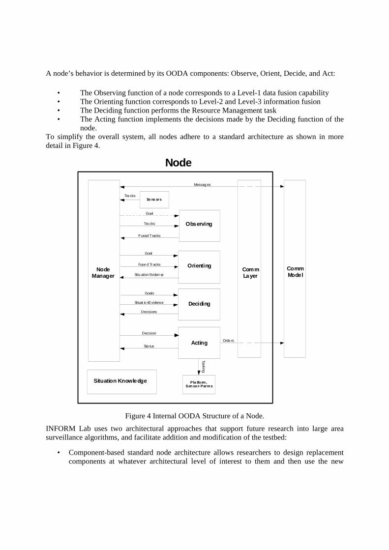
A node’s behavior is determined by its OODA components: Observe, Orient, Decide, and Act:
• The Observing function of a node corresponds to a Level-1 data fusion capability • The Orienting function corresponds to Level-2 and Level-3 information fusion • The Deciding function performs the Resource Management task • The Acting function implements the decisions made by the Deciding function of the
node. To simplify the overall system, all nodes adhere to a standard architecture as shown in more detail in Figure 4.
Figure 4 Internal OODA Structure of a Node.
INFORM Lab uses two architectural approaches that support future research into large area surveillance algorithms, and facilitate addition and modification of the testbed:
• Component-based standard node architecture allows researchers to design replacement components at whatever architectural level of interest to them and then use the new
NodeManager
Node
Observing
Orienting
Deciding
Acting
Goal
Fused T racks
Goal
Goals
Decisions
Decision
Sta tus
CommModel
Orde rs
Messag es
Se ns orsTra cks
Pla tform,Sen sor- Parms
Ta sking
Fuse d Tr acks
Situation Knowledge
Situ ation Eviden ceCommLayer
Tra cks
Situat io n Evidence

algorithms they wish to explore. This is achieved via a standard interface defined for each component in the architecture.
• Plug-and-play mechanism that provides standard component addition or replacement. This is achieved via Java JAR files and XML to construct the nested components during system initialization. Pretty much everything can be replaced via plug-and-play. This includes OODA components such as the Deciding box, or sub-components, such as the Planner. But it also includes the Environmental model, or components of the communication model.
The flexibility of this architecture will allow researchers to easily update or replace components and hence investigate many different approaches to data/information fusion and resource management with no software development beyond the content of the component they wish to re-design.
3 Goals and situation evidence
The power of distributed surveillance operations lies in the communication between nodes. For example, passing tasking orders or goals via a communication link influences the behaviour of the receiving nodes. Tasking orders are detailed instructions on how a node should move, that do not require the receiving node to make decisions. On the other hand, a goal is a high-level description of a task that requires further decision-making by the receiving node. In INFORM Lab, a goal is a data structure that has the following three elements:
1. Proposition 2. Area 3. Time interval
For example, a goal may state that the proposition isSmuggling is to be asserted in the area of northern Vancouver Island during the next 12 hours. The nodes usually form a strict command and control (C2) hierarchy. Only commanding nodes can order subservient nodes. However, the INFORM Lab architecture does not enforce this. Arbitrary relationships could be defined. This allows experimentation with other forms of organisation, for example peer-to-peer networks. Examples for relationships that are not C2 would be training relationships between nodes, where groups of nodes form an effective unit because they have trained together for a long time. The decision-making could choose to take these types of node relationships into account. Since OODA nodes are very general, a node can also represent a group of nodes in a hierarchy. For example, a squadron leader may be represented as a node that inherits the capabilities of an entire squadron. Such a node may decompose a given goal into sub-goals, which it can then send to subservient nodes for execution. For example, the commanding node may decide that the original goals best decomposed into several sub-goals, each with a smaller search area. Similarly, the commander node may decide that the original goal’s proposition should be decomposed into several sub-propositions, each being handled by a separate sub-goal, which is given to a specialized sub-node that is best suited to deal with it. The situation is depicted in Figure 5. As is shown in Figure 5, the parent node passes goals to its child nodes, and the child nodes pass situation evidence up to the parent. This situation could be viewed as follows: the goal is a
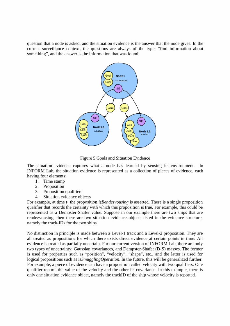
question that a node is asked, and the situation evidence is the answer that the node gives. In the current surveillance context, the questions are always of the type: “find information about something”, and the answer is the information that was found.
Figure 5 Goals and Situation Evidence
The situation evidence captures what a node has learned by sensing its environment. In INFORM Lab, the situation evidence is represented as a collection of pieces of evidence, each having four elements:
1. Time stamp 2. Proposition 3. Proposition qualifiers 4. Situation evidence objects
For example, at time t1 the proposition isRendezvousing is asserted. There is a single proposition qualifier that records the certainty with which this proposition is true. For example, this could be represented as a Dempster-Shafer value. Suppose in our example there are two ships that are rendezvousing, then there are two situation evidence objects listed in the evidence structure, namely the track-IDs for the two ships. No distinction in principle is made between a Level-1 track and a Level-2 proposition. They are all treated as propositions for which there exists direct evidence at certain points in time. All evidence is treated as partially uncertain. For our current version of INFORM Lab, there are only two types of uncertainty: Gaussian covariances, and Dempster-Shafer (D-S) masses. The former is used for properties such as “position”, “velocity”, “shape”, etc., and the latter is used for logical propositions such as isSmugglingOperation. In the future, this will be generalized further. For example, a piece of evidence can have a proposition called velocity with two qualifiers. One qualifier reports the value of the velocity and the other its covariance. In this example, there is only one situation evidence object, namely the trackID of the ship whose velocity is reported.
Node 1.1
Node1
commander
individual Node 1.2master
GoalGoal
Goal
Goal
Goal
Goal
Goal
Goal
SESE
SE
Goal
Goal
Goal

The situation evidence data structure stores in very raw form what is known from measurements about the situation. This was done intentionally to ensure that more sophisticated situation evidence concepts can relatively easily be accommodated in the future without being constrained by limiting assumptions at the bottom layer. For example, the situation evidence structure could be made to represent the Probability Distribution Function (PDF) of a proposition as a function of space and time. Since all the known raw information is stored already, the PDF or similar measures could be implemented in a rather straightforward manner. Even in its current form, the situation evidence provides key information for decision-making. For example, if the goal was to find a fishing boat in distress, then all that is required is to query the situation evidence object for the piece of evidence that has asserted the proposition isFishingBoatInDistress with the highest D-S value. If the value is high enough, the search is declared complete. The ship location can be found by asking for the position value stored for the position proposition for the ship’s track-ID.
4 Distributed Information Fusion
In an INFORM Lab OODA node, there are two modules responsible for Distributed Information Fusion (DIF): The Observing and the Orienting modules. The Observing function performs the traditional Level-1 data fusion tasks. For example, it performs track-level fusion for situation evidence objects that come from different nodes. For instance, in Figure 5, the track-IDs used in the SE objects sent by the child nodes Node 1.1 and 1.2 to the parent node need to be reconciled with each other and with the track-IDs used in the parent node itself. This task is made even more challenging by the often very sparse nature of the observations, and by the need to avoid data loops. The Orienting function, on the other hand, performs the Level-2 and Level-3 information fusion tasks. As can be seen in Figure 3, the Orienting box takes one or more goals and a single SituationEvidence object as input. The latter contains situation propositions that were previously trackID-fused by the Observing box. The Orienting box then tries to “prove” each goal proposition. Currently, the Orienting box is implemented as an expert system. A data fusion knowledge base, which is part of the node’s Situation Knowledge, contains rules that allow a ReasoningEngine to prove a goal proposition given a set of primitive propositions. The primitive propositions are logical statements such as isClose or isSlow. Some of these logical propositions may exist already in the input Situation Evidence. Others need to be created. The creation requires a Classifier that, for example, compares the estimated travel directions of two targets to assert the primitive proposition moveInParallel. The ReasoningEngine can then, for example, infer the proposition isRendezvousing from the primitive propositions isSlow, isClose and moveInParallel. Additional information may allow the drawing of further conclusions, for example, that a smuggling operation is under way. The asserted propositions are stored in a single SituationEvidence object, which is the output of the Orienting box. As an example, a partial proposition tree is shown in Figure 6.

Figure 6 Partial Proposition Tree
All propositions, all facts, and even all rules, are subject to uncertainty. The Classifier and the ReasoningEngine are both expected to take uncertainty into account. The uncertainty can be formalized in a large variety of ways. In the current version of INFORM Lab, Evidence Theory and Fuzzy Logic are used.
5 Dynamic Resource Management
The details of the current implementation of the Deciding module of the OODA node are shown in Figure 7. As can be seen, the OODA Deciding function is broken into five specialized decision-making modules, and a manager function.
Figure 7 Deciding Module
DecisionManager
Goals
Decision
Deciding
NodeManager
Scheduler
DynamicConfiguration
Advisor
Goal
Capabil ity Plan(s)
Mode P lan(s)
Scheduled P lan(s )
Planner
Capab ili ty Plan
Mode Plan
DynamicGoal
Generator
Goals
Dynamic Goal(s )
Situation E vidence
Situation Evidence
Situation Knowledge
DynamicConfiguration
Manager
Goals
Configuration Decis ions
IsSmuggling
IsRe ndezvousingIsFe rrying
IsClose IsSlow mov eInParallel

The DecisionManager takes goals and situation evidence as input and provides decisions as its output. A decision is a tasking order for a resource, or a goal that is given to, or removed from, a subservient node, or a request to reconfigure the C2 hierarchy. The DecisionManager coordinates the decision making process that is decomposed into five sub-functions that are briefly introduced in the following. It thereby provides a simple, standard interface to the NodeManager.
The Dynamic Goal Generator (DGG) takes node goals and situation evidence provided by the Orienting function of the node as input. As output it may generate additional goals or remove old goals. The DGG interprets the SituationEvidence object and decides if the evidence warrants a new goal. For example, if a goal is to find a sinking fishing boat, and the SituationEvidence asserts that isSinkingFishingBoat is very likely true in a certain small region, then the DGG may decide to issue a high-priority goal to check out just this small region in more detail. Alternatively, if the truth value of isSinkingFishingBoat is sufficiently high, it may decide that the goal has been achieved, and can therefore be removed.
A goal comes into the Planner module, which either splits it up into several new goals to be sent to subservient nodes, or it elaborates the goal by generating a capability plan. A capability plan breaks a goal into several subtasks. It also prescribes the order in which the tasks are to be executed. However, it does not specify the exact resource that is required to execute the task or the exact time at which it is to be done. Rather, the capability plan describes the required capabilities of the resource in a high-level manner, and may impose high-level timing constraints such as precedence.
The Dynamic Configuration Advisor (DCA) takes a capability plan as input and outputs a mode plan. A mode plan is similar to a capability plan, except that for each task the capability table is replaced by a list of concrete resources that the DCA recommends that the scheduler try.
The Scheduler takes all the mode plans as input and turns them into scheduled plans. A scheduled plan is similar to a mode plan, except that each task has exactly one resource assigned to execute it. A scheduled plan also has absolute times assigned to all tasks. The scheduler resolves any conflicts between all the active plans. It also optimizes its output according to a figure of merit, which is a weighted sum of criteria such as completion time and completion cost. The Scheduler enlists the services of a separate path planner to compute the trajectories that the resources are tasked to follow. The path planning is a service that is provided by the testbed. This allows the scheduler to concentrate just on scheduling, and decouples it from having to know about specific resource capabilities, land contours, and trajectory optimization techniques.
Finally, the Dynamic Configuration Manager monitors the communication network and the node capabilities, and based on this and other information, makes resource allocation decisions. For example, it may decide to reallocate a particular aircraft from one squadron to another squadron because this enables both squadrons to fulfill their goals. It also monitors failure of communication in nodes, and makes resource allocation decisions accordingly. This is explained in more detail in the next section.
6 Auto-Configurable Information Fusion Architectures
Connectivity amongst fusion nodes allows sharing information among many fusion nodes. A multi-layer network architecture, called Dynamic Resource Configuration & Management Architecture (DRCMA), is adopted to represent a distributed fusion network. A key requirement

is the need for efficient management of information fusion nodes under dynamically changing and essentially unpredictable conditions. To facilitate dynamic reorganization and to avoid the bottleneck of centralized fusion systems, a multi-agent based design approach is considered in order to explore robust and efficient fusion of heterogeneous data and information. The DRCMA model is formally described in terms of a distributed Abstract State Machine (ASM) with real-time constraints. The resulting machine model abstractly characterizes the dynamic properties of the distributed fusion architecture and serves as an abstract computational framework for requirements specification, design analysis and validation of the key system attributes prior to actually building the system.
The ASM formalism is well known for its versatility in semantic modeling of algorithms, architectures, languages, protocols and virtually all kinds of sequential, parallel and distributed systems. Concurrently executing tasks of a distributed fusion process change dynamically due to the dynamic nature of mission requirements. Resources allocated to tasks change dynamically as a result of unavoidable instabilities in the resource environment. This situation calls for reconfigurable applications that can adapt to internal changes in resource requirements and to external changes affecting the available resources. Sensor platforms are combined into clusters that can operate semi-autonomously. Dynamic reconfiguration of resource clusters is performed in an ad hoc manner using ‘plug and play’ mechanisms. At any time, additional resources can join clusters on demand based on their sensor capabilities and geographic position. Fault tolerant behaviour is crucial for avoiding catastrophic system failures as a result of communication failures (e.g., broken communication links, corrupted or lost messages) and partial or total resource failures (e.g., in disaster situations). In many respects, requirements and design principles of the distributed information fusion system resemble those of mobile ad hoc networks. Complex control structures and the need to deal with component and communication failures require investigating different organization structures (e.g., decentralized versus centralized). This will be realized by introducing a concept of generic control center, such that a uniquely identified control center is associated with each individual cluster in a hierarchy of logically linked resource clusters. At the bottom level, each physical sensor platform has its own control center. The proposed system will have the following functions:
• Task Decomposition: principles for decomposing complex tasks (goals) into subtasks based on common patterns and schemes for mapping tasks onto resources. This also includes an abstract characterization of tasks according to their resource requirements and the orchestration of resources for processing tasks,
• Resource Clustering: composition principles for a systematic clustering of resources based on abstract logical representations of their physical capabilities (e.g., sensor capabilities, mobility constraints, time restrictions). Primitive resources are joined to form composite resources with richer behaviours, as derived by an attribution scheme defined over a set of logical resource descriptors,
• Resource Management: dynamic resource management policies to control resource migration between clusters based on prioritization schemes for resource selection and management of resource pools,
• Fault Tolerance: robust mechanisms for dynamic resource linking (‘plug and play’) auto-reconfiguration and semi-autonomous operation of resource clusters,
• Communication Framework: i) communication of information from control centers to resources and from resources to control centers; ii) intelligent exchange of information

that prevents propagation of outdated information (information pollution); iii) management of meta-data required to identify the origin of information, the associated time line and life time.
Overall, the proposed design is characterized by its concurrent and reactive nature, making it difficult to predict the resulting system behavior with sufficient detail and precision under all circumstances. Hence, there is a need for formalism. It allows us to not only reason about specification and design issues, but also uncover deficiencies that would otherwise go unnoticed. Finally, model-based systems engineering demands for abstract executable specifications as an instrument for design exploration and experimental validation through simulation and testing, as well as by means of symbolic execution. The ASM formalism, in combination with related tool environments, directly supports this modeling paradigm.
7 Vignettes
The fusion research is focused by “vignettes”, scenarios that are instantiated within the framework established by the vignette’s geographical location and set of available entity types. We looked at two different vignettes within INFORM Lab: a cooperative search and a non-cooperative search.
7.1 Cooperative Search
This vignette addresses a simplified version of a cooperative-search scenario. A boat in distress is reported at 8 km southeast of Chrome Island in the Strait of Georgia in the inland waters off British Columbia. This triggers a cooperative search, i.e. a search where the target wants to be rescued and behaves in a transparent way to facilitate being found. At the time of the reception of the boat-in-distress call, an Aurora aircraft on a surveillance task is 18 minutes from completing that task and arriving at Comox Air Force base. An Aurora is on the ground at Comox but needs 20 minutes prep time. This simple scenario is complex enough to highlight important basic features of distributed information fusion (DIF) and resource management (RM), and the testbed architecture itself. RM must choose between the Aurora busy on reconnaissance, or the Aurora on the ground that requires prep time to get airborne. This of course depends on the initial conditions of the vignette. The Aurora provides surveillance, while a Cormorant helicopter provides identification of the ship in distress. A Cormorant is ready close by at Comox, and another Cormorant is ready at Vancouver, which is further away. Both are dispatched and the timing of their arrival results in different scenarios playing out since the ship in distress drifts with the current, and a large number of active shipping and other objects in the area complicate the search mission. For this type of vignette, RM must evaluate which of the two available Auroras to utilize, choosing between one doing a routine background patrol or a dedicated search Aurora. DIF must then correctly use the sensor data from the selected Aurora to identify likely targets that need closer inspection by the helicopters. RM must react to this information the moment the DF provides it, and then dynamically re-schedule the helicopters to go and verify the likely targets based on their proximity to the current location of the helicopters.

Figure 8 Cooperative Search Vignette
The visualizer in Figure 8 allows the researcher to step through each instant of the simulation run and display the tracks of the targets and platforms together with helpful labels. When new, likely targets are found, it marks their location in the display. Figure displays an instant towards the end of the simulation run. The Aurora has already arrived in the search area and is flying a zigzag search pattern to scan the area for likely targets. The two helicopters have also already arrived. The helicopter from Comox arrived before the Aurora and started to fly a tightly knit zigzag search pattern. However, after the Aurora had arrived and found likely targets, the helicopter abandoned its search pattern and flew to investigate the likely targets. To do this it started a spiral search pattern around the reported location of the new target. The spiral pattern was abandoned the moment the target was declared false. Finally, the second helicopter arrived, and both shared the task of verifying likely targets thereby speeding up the search significantly.
7.2 Non-Cooperative Search
In contrast to the first vignette, this vignette features targets that don’t want to be found. It involves a freighter carrying illegal immigrants, which are off-loaded to zodiacs. This scenario features deceptive maneuvers and potentially intentionally false sensor data, and thus requires a sophisticated DIF and an evolution of the RM capability over that used for the 1st vignette. The mission focuses on a threat situation that develops off the northwest tip of Vancouver Island. A freighter coming from the eastern Pacific carrying illegal immigrants arrives near Cape Scott on northern Vancouver Island. It leaves a known sea-lane off Cape Scott to begin a manoeuvre to off-load the illegal immigrants. It does not use the Automatic Identification System (AIS) to identify itself, rather - when it suspects it is being watched – it may use an AIS identification of another freighter scheduled to be in the area, in an attempt to confuse
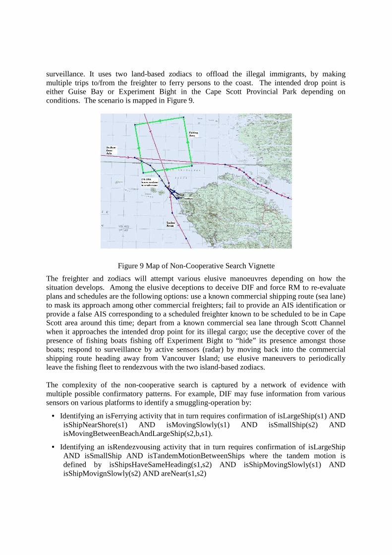
surveillance. It uses two land-based zodiacs to offload the illegal immigrants, by making multiple trips to/from the freighter to ferry persons to the coast. The intended drop point is either Guise Bay or Experiment Bight in the Cape Scott Provincial Park depending on conditions. The scenario is mapped in Figure 9.
Figure 9 Map of Non-Cooperative Search Vignette
The freighter and zodiacs will attempt various elusive manoeuvres depending on how the situation develops. Among the elusive deceptions to deceive DIF and force RM to re-evaluate plans and schedules are the following options: use a known commercial shipping route (sea lane) to mask its approach among other commercial freighters; fail to provide an AIS identification or provide a false AIS corresponding to a scheduled freighter known to be scheduled to be in Cape Scott area around this time; depart from a known commercial sea lane through Scott Channel when it approaches the intended drop point for its illegal cargo; use the deceptive cover of the presence of fishing boats fishing off Experiment Bight to “hide” its presence amongst those boats; respond to surveillance by active sensors (radar) by moving back into the commercial shipping route heading away from Vancouver Island; use elusive maneuvers to periodically leave the fishing fleet to rendezvous with the two island-based zodiacs. The complexity of the non-cooperative search is captured by a network of evidence with multiple possible confirmatory patterns. For example, DIF may fuse information from various sensors on various platforms to identify a smuggling-operation by:
• Identifying an isFerrying activity that in turn requires confirmation of isLargeShip(s1) AND isShipNearShore(s1) AND isMovingSlowly(s1) AND isSmallShip(s2) AND isMovingBetweenBeachAndLargeShip(s2,b,s1).
• Identifying an isRendezvousing activity that in turn requires confirmation of isLargeShip AND isSmallShip AND isTandemMotionBetweenShips where the tandem motion is defined by isShipsHaveSameHeading(s1,s2) AND isShipMovingSlowly(s1) AND isShipMovignSlowly(s2) AND areNear(s1,s2)
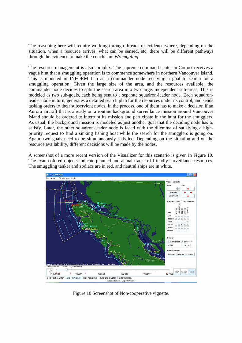
The reasoning here will require working through threads of evidence where, depending on the situation, when a resource arrives, what can be sensed, etc. there will be different pathways through the evidence to make the conclusion isSmuggling. The resource management is also complex. The supreme command center in Comox receives a vague hint that a smuggling operation is to commence somewhere in northern Vancouver Island. This is modeled in INFORM Lab as a commander node receiving a goal to search for a smuggling operation. Given the large size of the area, and the resources available, the commander node decides to split the search area into two large, independent sub-areas. This is modeled as two sub-goals, each being sent to a separate squadron-leader node. Each squadron-leader node in turn, generates a detailed search plan for the resources under its control, and sends tasking orders to their subservient nodes. In the process, one of them has to make a decision if an Aurora aircraft that is already on a routine background surveillance mission around Vancouver Island should be ordered to interrupt its mission and participate in the hunt for the smugglers. As usual, the background mission is modeled as just another goal that the deciding node has to satisfy. Later, the other squadron-leader node is faced with the dilemma of satisfying a high-priority request to find a sinking fishing boat while the search for the smugglers is going on. Again, two goals need to be simultaneously satisfied. Depending on the situation and on the resource availability, different decisions will be made by the nodes. A screenshot of a more recent version of the Visualizer for this scenario is given in Figure 10. The cyan colored objects indicate planned and actual tracks of friendly surveillance resources. The smuggling tanker and zodiacs are in red, and neutral ships are in white.
Figure 10 Screenshot of Non-cooperative vignette.

The search area and the situation evidence probability is depicted in the screenshot of Figure 11.
Figure 11: Visualizer showing Situation Evidence probability for search area.
Figure 12 provides a good illustration for a sophisticated collaborative search of an area by several resources driven by dynamically updated probability-of-detection and effort-allocation maps. In this figure, the red color indicates higher effort allocation values. The cyan lines indicate the trajectories of two cooperating UAVs.

Figure 12 Screenshot showing planning for search area
A variety of output options is available to the user as shown in Figure 13.
Figure 13: Viewer Showing Various Output Options

8 Future work
INFORM Lab is available to University researchers (notably from University of Victoria and Simon Fraser University) and this constitutes an important part of algorithmic development. Currently, 4 research themes are being developed. They are outlined further below, with a short outline for each.
1. Information Routing in Distributed Decision Networks.
A network is a set of connected nodes. A node might be a provider, receiver (decision maker) or relay of information. The connectivity between nodes is characterized by a set of attributes and constraints such as capacity, reliability and latency. A decision maker needs to specify a time dependent utility function for each required piece of information. The same information can be provided by different nodes with different accuracy and sizes. The problem is therefore to optimize the information sharing between providers and decision makers by maximizing the overall utility and the reliability of the paths under system constraints. A real-case surveillance scenario consists of a set of entities collaborating and exchanging information so as to achieve a common goal.
2. Multi-Objective Location-Allocation Planning of Heterogeneous Network Infrastructure.
The Multi-objective Location−Allocation Planning of Heterogeneous Network problem consists in optimizing the communication coverage of an existing network by deploying new nodes from a set of candidate sites and integrate them with an existing infrastructure. The purpose is to find the optimal number, position, communication types and connections in a special area of coverage. Planning integrating techniques are based on user models for dealing with both placement and connections problems where based on multi-objective functions that are: maximizing the communication coverage, the minimization of agent placement and communication devises costs and the maximization of the total capacity bandwidth in the network. In addition to these three objective functions, the solution must satisfy a set of constraints related to networks planning as: energy constraints (bandwidth, power, link), connection constraints, capacity constraints, maximum number of connections link constraints, geographical constraints, etc. An initial implementation of the optimization algorithm will be integrated and tested in INFORM Lab.
3. Generating Vignettes for Coastal Surveillance Operations.
The main goal of this project is to generate realistic and concrete vignettes for the marine safety and security domain. The output of the Vignette Generator is the description of a vignette that can be used in the INFORM Lab simulation environment; therefore it facilitates the simulation process of different situations and scenarios by users, and the testing and evaluation of algorithms by developers. Generating these vignettes in a semi-automatic way requires not only a complete set of vignette elements, but also a collection of parameters, constraints, and algorithms to simulate real-world situations. In this project, we are trying to identify and define a repository of vignette elements and their required parameters, constraints, etc. An approach for defining the vignette elements has been defined and also how to combine them to generate a concrete vignette.

4. A Comprehensive High-Level Design of Continual Planning.
Automated planning techniques have made possible the automation of complex decision making, both for device control and providing decision support. However, traditional planning algorithms assume full knowledge and predictability; it is very rare that real world applications can rely on either of these. While effective planning algorithms exist, such as Hierarchical Task Networks, it is not clear exactly how such an algorithm should best fit into an on-line system. I propose a high-level model to show how this can be done within the context of an OODA loop. This model contains the essential features of a robust and flexible planning system, and is meant to act as a base design for continual planning systems in general. A model specification in the CoreASM formal language has been written, and linked to the INFORM Lab simulation environment for testing.
9 Conclusion
This paper described the latest version of INFORM Lab (previously reported in [2, 3]) which provides a flexible multi-agent architecture that allows researchers to test dynamic resource management, distributed data fusion, and dynamic resource management algorithms in a setting that is realistic enough to draw valid conclusions about the effectiveness of net-enabled large area costal surveillance applications. We hope that INFORM Lab will be a useful tool for researchers in the domain.
References
[1] Col. John R. Boyd, Patterns of Conflict, Dec. 1986.
[2] H. Wehn, R. Yates, P. Valin, A. Guitouni, É. Bossé, A. Dlugan, H. Zwick, A Distributed Information Fusion Testbed for Coastal Surveillance, Fusion 2007, Québec City, July 9-12, 2007.
[3] Valin, P., Bossé, E., Guitouni, A., Wehn, H., Happe, J., Testbed for Distributed High–Level Information Fusion and Dynamic Resource Management, FUSION 2010, Edinburgh, Scotland, 26-29 July 2010.
High-level Closed-loop Fusion and Decision Making with INFORM Lab
A. Guitouni, Pierre Valin, H. Wehn, J. Happepresented by Dr. Pierre ValinICCRTS 2011

2
Introduction - Large Volume Surveillance Problem (in peacetime)
• Non-denial surveillance (detect, track, and identify) of all seafaring vessels in a large littoral volume of surveillance
• Non-denial surveillance and tracking of all small vessels and coastal traffic in specific areas of interest when alerted
• Identification and tracking of Vessels of Interest• Maximization of coverage of the area of responsibility,
while minimizing risk and response time to unforeseen events
• Data sharing and information fusion to provide situation awareness to decision makers to allow appropriate military or law enforcement response.
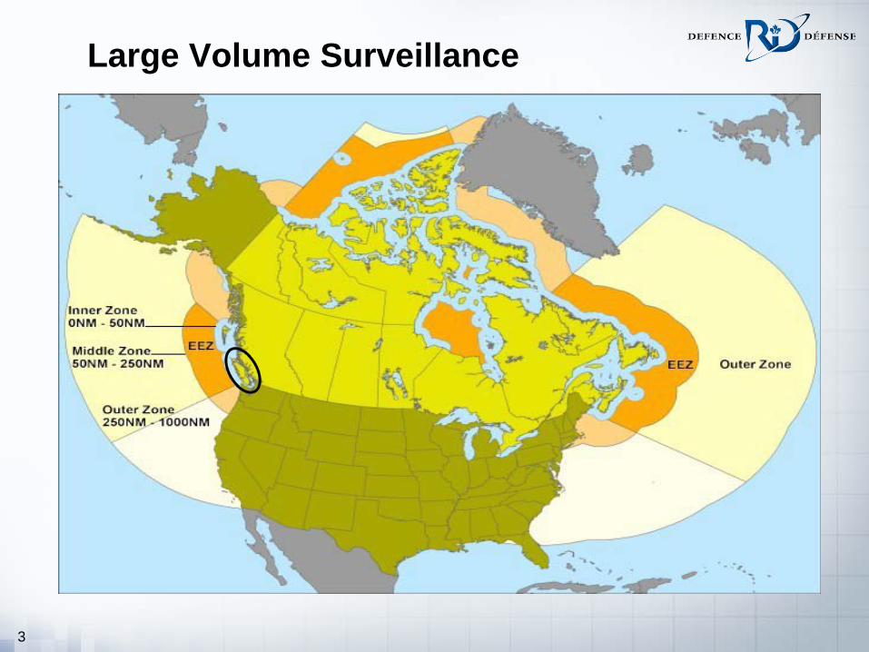
3
Large Volume Surveillance
4
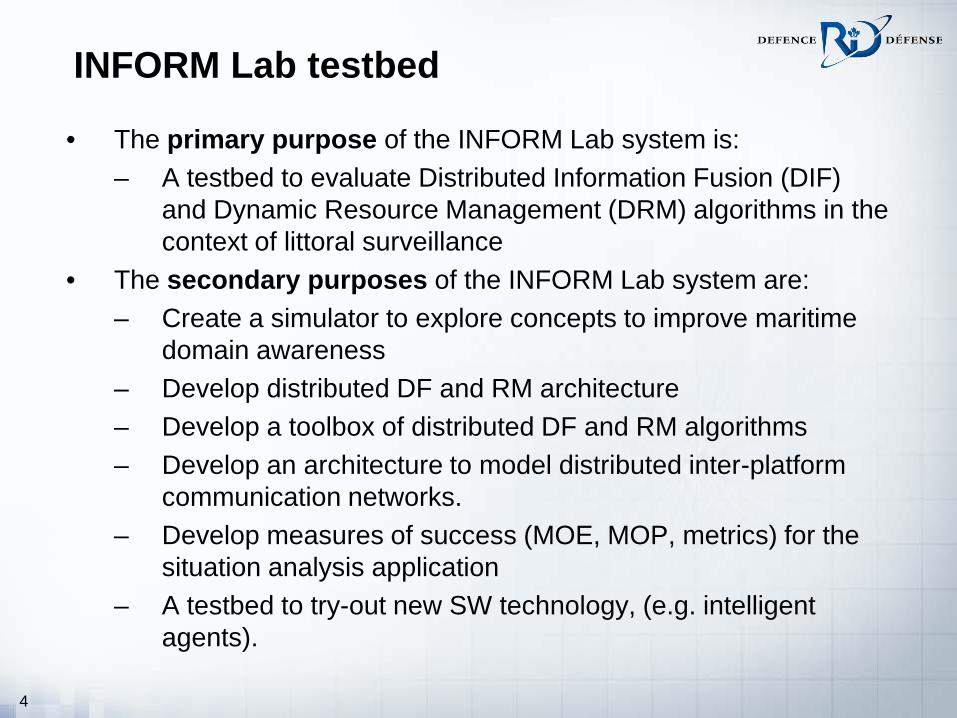
INFORM Lab testbed
• The primary purpose of the INFORM Lab system is: – A testbed to evaluate Distributed Information Fusion (DIF)
and Dynamic Resource Management (DRM) algorithms in the context of littoral surveillance
• The secondary purposes of the INFORM Lab system are: – Create a simulator to explore concepts to improve maritime
domain awareness – Develop distributed DF and RM architecture – Develop a toolbox of distributed DF and RM algorithms– Develop an architecture to model distributed inter-platform
communication networks.– Develop measures of success (MOE, MOP, metrics) for the
situation analysis application– A testbed to try-out new SW technology, (e.g. intelligent
agents).

5
System Development Guidelines
• Uses open standards • Uses modern architecture (e.g. Service Oriented
Architecture, Agents)• Is flexible:
– plug-and-play – toolbox for platforms & sensors, – “net-centric” play vs “command-central” play
• Has documentation on how to add new components to the testbed
• Makes it easy to generate new demonstrations

6
INFORM Lab Components
InformLabtrack
Distributed FusionAlgorithms
Agent Network Technology
Situation Assessment
Distributed Resource Mgmnt.
Algorithms
SOA Services
WFS GIS services, External Decision Support Systems
Metrics / Scenarios / Test data
OODA Agent Architecture
smuggling
freighter
zodiac
Toolbox / Library • auto-configurable architecture
• distributed information fusion
• distributed dynamic resource
management
• goals and situation evidence
applied to 2 scenario types
and multiple vignettes

7
INFORM Lab multi-agent architecture
Node
Node
Node
Editor
Testbed
Viewer
XML
Con
figSc
ript
XML
Vign
ette
log
file
Messages
SensorsPlatform
Node A
OODA
SensorsPlatform
Node B
OODA SituationKnow ledge
CommLayer
CommLayer- Commands
- Information- Requests
SituationKnow ledge

8
INFORM Lab platforms

9
Internal structure of an OODA node
NodeManager
Node
Observing
Orienting
Deciding
Acting
Goal
Fused Tracks
Goal
Goals
Decisions
Decision
Status
CommModel
Orders
Messages
SensorsTracks
Platform,Sensor-Parms
Tasking
Fused Tracks
Situation Knowledge
Situation EvidenceCommLayer
Tracks
Situation Evidence

10
Goals and Situation Evidence
Node1.1
Node1commander
individual Node1.2master
GoalGoal
Goal
Goal
Goal
Goal
Goal
Goal
SESE
SE
Goal
Goal
Goal
Goal example: proposition isSmuggling is to be asserted in the area of northern Vancouver Island during the next 12 hours
SE = Situation Evidence has 4 elements:
1. time stamp
2. proposition
3. proposition qualifiers
4. SE objects
e.g. velocity with two qualifiers
1. value
2. covariance

11
More details about C2 Node hierarchySlave (UAV): Orientation and Decision function are switched off; Receives tasking orders from a Master and acts on them directly. Forwards the readings of its built-in sensors directly to its Master.
Autonomous Individual (helicopter): Takes a goal as input; manages its own sensor(s); does not command other nodes; may get tracks from other nodes.
Master (group leader): Takes goal as input; manages a group of slave nodes; sends schedules to slave nodes; receives tracks or situation evidence from slave nodes, e.g. UAV controllers.
Commander: Takes goal as input; issues goals to autonomous individuals, masters, and other commander nodes; compiles situation evidence obtained from sub-servant nodes into a common situation understanding, e.g. the captain of a large ship or a base commander.
Node1.2.2
Node1.1
Node1
Node1.2.2.1 Node1.2.2.2
commander
group leader
slave slave
individual
Node1.2
commander
Node1.2.1
individual
Goals
SE &
RequestsG
oals
SE &
Req
uest
s
Goals
SE &
RequestsG
oals
SE &
Req
uest
s
Tasking
Orders
Tracks
Task
ing
Ord
ers
Trac
ks

12
OODA node and INFORM Lab functions• The Observing function of
a node corresponds to a Level-1 data fusion capability
• The Orientation function corresponds to Level-2 information fusion
• The Deciding function performs the Resource Management task
• The Acting function implements the decisions made by the Deciding module.

13
Distributed Information Fusion
• Goals are decomposed into subgoals all the way down down to Situation Evidence
• Orienting implemented as an Expert System
• Uncertainty formalized by evidence theory and fuzzy logic
IsSmuggling
IsRendezvousingIsFerrying
IsClose IsSlow moveInParallel

14
Dynamic Resource Management
DecisionManager
Goals
Decision
Deciding
NodeManager
Scheduler
DynamicConfiguration
Advisor
Goal
Capability Plan(s)
Mode Plan(s)
Scheduled Plan(s)
Planner
Capability Plan
Mode Plan
DynamicGoal
Generator
Goals
Dynamic Goal(s)
Situation Evidence
Situation Evidence
Situation Knowledge
DynamicConfiguration
Manager
Goals
Configuration Decisions
DCM monitors the comms and the node capabilities, and makes resource allocation decisions.
DGG takes node goals and SE provided by Orienting as input, and outputs additional goals or removes old goals.
A goal comes into the Planner module, and may split it up into several new goals to be sent to subservient nodes, or it elaborates the goal by generating a capability plan.
DCA takes a capability plan as input and outputs a mode plan.

15
Auto-configurable IF architecturesA multi-layer network architecture, called Dynamic Resource Configuration & Management Architecture (DRCMA), is adopted to represent a distributed fusion network.
A key requirement is the need for efficient management of IF nodes under dynamically changing conditions.
The DRCMA model is formally described in terms of a distributed Abstract State Machine (ASM) with real-time constraints.
It has 5 functions:1. Task Decomposition2. Resource Clustering3. Resource Management4. Fault Tolerance5. Communication Framework, for
• communication from control centers to resources and vice versa• intelligent exchange of information• management of meta-data required to identify the origin of info

16
Vignette 1: Cooperative Search and Rescue of a fishing boat in distress – platforms
• 1 Target: the fishing boat
• 10 other boats
• 2 CP-140s: the CP-140s will be on missions in the area doing a normal reconnaissance activity
• 2 Cormorants – one from Comox, one from YVR
• Clutter - The area within 30 nm of the report contains numerous adrift and fixed clutter
BASICALLY THIS IS A VIGNETTE TO TEST THE FUNCTIONALITY OF THE TESTBED

17
Cooperative Search vignette

18
Vignette 1 overall final situation close-up

19
Vignette 2 – Non-cooperative search• Goals
Test OODA Nodes & their components
Show hierarchical Nodes & Goals
Show Non-Cooperative Search behaviour
Show inter-node communication
GIS-based path-planning
• Key Behaviours
Rendez-vous of mother-cargo-ship CS-UNK with 2 zodiacs
Ferrying behaviour of zodiacs between beach & CS-UNK
Suspicious behaviour: CS-UNK deviating from sea lane, failing to use AIS
Elusive behaviour: CS-UNK and zodiacs disperse when they sense being watched to avoid being detected as rendez-vous-ing
THIS VIGNETTE IS DEMANDING ADVANCED DISTRIBUTED
FUSION AND DYNAMIC RESOURCE MANAGEMENT

20
Network design for vignette 2

21
Vignette 2 with intended behaviours

22
Vignette 2 screen capture – initial situation

23
DIF example
• Identifying an isFerrying activity that in turn requires confirmation of isLargeShip(s1) AND isShipNearShore(s1) AND isMovingSlowly(s1) AND isSmallShip(s2) AND isMovingBetweenBeachAndLargeShip(s2,b,s1)
• Identifying an isRendezvousing activity that in turn requires confirmation of isLargeShip AND isSmallShipAND isTandemMotionBetweenShips where the tandem motion is defined by isShipsHaveSameHeading(s1,s2)AND isShipMovingSlowly(s1) AND isShipMovignSlowly(s2) AND areNear(s1,s2)

24
Vignette 2 screen capture – search begins

25
Vignette 2 screen capture – SE for search area

26
Vignette 2 – planning for a search area

27
Vignette 2 – output options

28
Conclusions and outlook• 2 scenarios/vignettes have been implemented and tested
– one cooperative SAR – easy– one non-cooperative search – challenging
• Level-2 fusion for situation analysis• Could answer the following questions:
– What sensors and what platforms should be used and how, in order to maximize situation awareness?
– How to fuse information from heterogeneous systems? – What are the optimal information sharing and distributed
information fusion architectures? – How to dynamically manage ad-hoc remote communication
networks? • On-going testbed work to be reported at regular intervals
– University papers report on algorithmic subsets of testbed (SFU, U Victoria for DCM, U Calgary for DIF, SFU for DRCMA)