17153 - sl 900 manual v2 -...
TRANSCRIPT

SL 900Instruction Manual
Version 2.9
illonrecision
Products, Inc.
Manufacturers of The World’s FinestLoading Equipment

Dillon Precision Products, Inc.8009 E. Dillon’s WayScottsdale, AZ 85260
(480) 948-8009FAX (480) 998-2786
Web Site: www.dillonprecision.comE-mail: [email protected]
Technical Support & Customer Service(800) 223-4570
On the cover…The SL 900 is pictured with optional accessories:Low Powder Sensor #16306Aluminum Roller Handle #17950Other accessories available for the SL 900 include:20 gauge conversion #2213828 gauge conversion #2213920/28 casefeed plate #97045Machine Cover #13329The Blue Press, Dillon’s monthly catalog, has a complete listing of accessories available for all machines.
Part #17153 Spot Manuals SL 900 Manual Folder SL 900 Manual.V2.9 10/01 WJC

TABLE OF CONTENTS
Parts List, Schematics and Diagrams 5 - 17SL 900 Machine Mounting Assembly 6Upper Machine Assembly 7Shot Container Assembly 8Casefeeder Assembly & Parts List 9Casefeeder Bowl Mount & Casefeed Assembly to Frame 10Lower Machine Assembly 11Toolhead Assembly 12Platform Assembly 13Primerfeed Assembly & Installation 14Automatic Powder Measure Assembly 15Shot Dispenser Assembly 16Wad Swing Arm Assembly 17Finished Shotshell Dimensions 17
General Machine Information 18 - 19Step-by-Step Preliminary Assembly 19 - 23Factory Settings 24 - 25Filling the Machine with Components – What’s First? 26 - 29Let’s Begin Making a Few Rounds 29 - 31Changes and Adjustments 31 - 37
Adjusting the Collet Sizer 31Powder Die/Funnel Adjustments 32Adjusting the Automatic Powder System, Powder Charge Weight 32Adjusting the Wad and Shot Station 32 - 33Adjusting the Starter Crimp Die 33Removing the Shot From the Machine 33 - 34Removing the Toolhead 34 - 35Shellplate Removal 35 - 36Switching to Another Powder 36The Primer System 37Gauge Conversion - 28 ga. 38 - 42Gauge Conversion - 20 ga. 43 - 47
Troubleshooting Section 48 - 49Primer System 48Casefeeder 48 - 49General 49
Lube Points 50Suggested Settings 51

5
SL 900 Parts ListPart # Description10716 Primer Spring Cap 12577 1/2-20 Jam Nut 13311 Spring Pin 13418 Shellplate Bolt 13485 Mainshaft 13613 Clamp 13667 Index Pawl 13677 Ring Indexer 13700 Link Arm Shoulder Pin 13701 3/32x3/8 Dowel Pin13738 10 Stainless Washers 13742 1/2 E-Clip13773 8-32 Nut13789 1/4-28 Set Screw 13791 Indexer Return Spring 13793 Collar Roller 13799 Blue Wing Nut 13801 Tinnerman Nut 13830 Mainshaft Pivot Pin 13837 1/4 E-Clip 13840 Hitch Pin Clip13841 Nylock Nuts 13848 Bellcrank Bushing 13856 1/4 Washer SAE 13858 Rod Compression Spring 13871 Bellcrank Cube 13891 3/8 Index Ball 13895 10-24x3/8 BHCS13896 1/4-20 x 3/8 BHCS 13911 1/4-20 x 2 3/4 Bolts 13923 1/4-28 Brass Tip Set Screw 13937 Slide Return Spring 13938 Pawl Spring 13943 1/4-28 Adjustment Bolt 13958 1/4 Washer 13966 1/4-28 x 3/4 SHCS 13988 1/4-20 Nuts 13989 10-24 x 5/8 SHCS 13996 10-32 Set Screw14008 Toolhead Pins 14013 8-32x3/8 SHCS14023 8-32 x 3/4 BHCS 14026 8-32 x 1/2 BHCS14037 10-24 x 3/4 SHCS 14041 1/4 Wave Washer 14118 Index Ball Spring 14574 Case Insert Slide Spring Cap 14689 8-32 x 1/4 BHCS 14808 Collar Roller Bushing 14922 Link Arms 16065 650 Machine Mounts 16209 Spent Primer Cup Bracket 16221 1/4 Fender Washer16222 1/4-20 x 11/2 Hex Bolts 16340 10-32 Nylock Nut16667 Toolhead 16668 Toolhead Die Lockplate 16670 SL Crank 16671 Indexing Block 16672 Shotshell Chute
Part # Description16675 Shellplate, 12 ga.16676 Ejector Wire 16677 Wad Swing Arm 16678 Wad Guide Sleeve 16679 Sleeve Compression Spring 16680 1/16 x 1/2 Roll Pin 16681 Wad Guide 16682 Swing Arm Torsion Spring 16683 Case Insert Slide 16684 Slide Block 16691 Primer Transfer Arm 16692 Arm Pivot Pin 16693 Transfer Arm Spring 16694 Station Two Locator 16695 Locator Pivot Screw 16696 Locator Torsion Spring 16697 Case Insert Ramp 16698 SL Platform 16699 Spent Primer Cup 16700 Primer Seater Pin 16701 Bushing 16702 Primer Seater Spring 16705 SL Casefeed Tube 16707 Phish Compression Spring 16708 Casefeed Phish 16709 Camming Pin 16710 Clear Primer Tray Cover 16711 Primer Feedplate 16713 SL Primer Slide Upper 16714 Slide/Bellcrank Spring 16717 Primer Feed Cam 16721 Tray Mounting Bracket 16723 Primer Feed Body 16724 Shot Hopper 16725 Shot Dispenser Body 16726 Shot Drop Tube, 12 ga. 16727 Shot Dispenser Bellcrank 16731 Spring (Bellcrank Assembly)16732 Pivot Pin16733 Shot Bar Return Rod 16734 Rod Bushing 16735 Shot Body Collar 16736 Body Collar Adjustment Screw 16737 Collar Guide/Clamp 16738 Shot Bar 16739 Shot Bar Insert 16740 3/8-16 Half Dog Set Screw 16741 Depriming Pin 16742 SL Sizer Collet Sleeve 16743 Collet Sizer Die, 12 Ga. 16744 SL Powder Die 16746 Expander Powder Funnel 16747 Starter Crimp Die 16748 Dillon Starter Crimp Insert-1 16750 Final Taper Crimp Die, 12 Ga. 16751 Final Seat Plug, Rem. 12 Ga. 16752 5/8-18 Jam Nut 16753 Locator Buttons 16904 1 1/2-10/32 SHCS17123 SL 900 Casefeed Post
Part # Description17124 Shot Post 17125 Dillon Bin 17126 Locator Button Spring 17130 Casefeed Sleeve, 12 Ga. 17131 Casefeed Body 17132 Primer Drop Tube 17134 Primer Bellcrank 17138 Clear Hopper Lid 17139 Shot Dispenser Fitting 17140 Pin (Bellcrank Assembly)17141 1/4 Hardened Washer 17142 Dispenser Top 17143 Dispenser Top Clear Lens 17146 Rubber Insert 17147 Powder Die E-Clip 17148 1 1/4 Die Lock Ring 17149 1.0 Die Lock Ring 17153 Manual 17182 SL Frame Machined 17202 Shot Fitting E-Clip 17350 Powder Bar Return Rod 17351 Die Lock Bolt 17352 Spring Button 17353 Phish Spring Socket17354 Gate 317472 #8 Washer .032 Thick17474 10-32 x 5/8 Tray Cover Screw17476 Shot Drain17477 Collet Sizer Spring17479 Clear Industrial Vinyl Tubing17509 Box 17573 Shot Drain Ext. Spring17601 Washer .100 Thick17603 Black Knob17604 Clevis Pin17637 1/4-20 x 4 1/2 Hex Head Screw17639 .175 dia. x 1/4-20 Post17812 Primer Seater Assembly17836 Final Seat Plug, A-A 12 Ga. 17837 Tyton Clamp 17838 P/M Lock Link17839 P/M Slotted Bellcrank17843 SL 900 Foam Insert Set17899 Stem Screw17909 Eight Star Crimp20782 Dillon Powder Measure 22134 Shot Dispenser Assy - 12 ga.22183 Roller Handle Assembly97037 12 Ga. Casefeeder – 110v97120 Red FlagN/A Lock Link N/A Lock Link Torsion Spring N/A Pivot Pin N/A Return Spring Pin N/A Shot Bellcrank Rivet N/A SL Bellcrank Stud N/A Spare Parts Bag
6
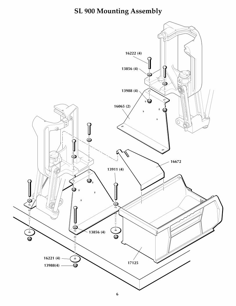
SL 900 Mounting Assembly
16065 (2)
16672
17125
16222 (4)
13856 (4)
13988 (4)
13911 (4)
13856 (4)
16221 (4)
13988(4)

7
Upper Machine Assembly
1667617123
13418
16675
13966
1366713791
13938
1367716699
13856
17637
13989
13989
17637
13856
13613
13988
13613
13613
13988
17124

8
Shot Container Assembly
��
��
16724
17202
17139
17478
17479
17202
17139
17478
9
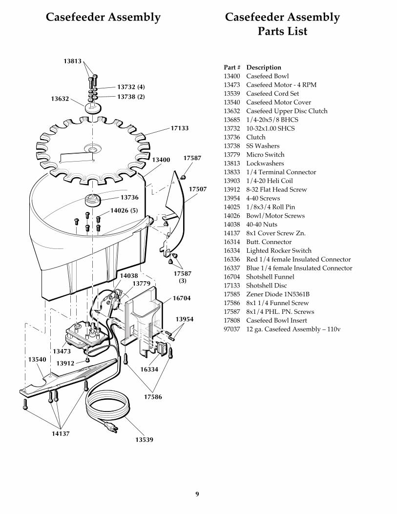
Casefeeder Assembly Casefeeder Assembly Parts List
Part # Description13400 Casefeed Bowl13473 Casefeed Motor - 4 RPM13539 Casefeed Cord Set13540 Casefeed Motor Cover13632 Casefeed Upper Disc Clutch13685 1/4-20x5/8 BHCS13732 10-32x1.00 SHCS13736 Clutch13738 SS Washers13779 Micro Switch13813 Lockwashers13833 1/4 Terminal Connector13903 1/4-20 Heli Coil13912 8-32 Flat Head Screw13954 4-40 Screws14025 1/8x3/4 Roll Pin14026 Bowl/Motor Screws14038 40-40 Nuts14137 8x1 Cover Screw Zn.16314 Butt. Connector16334 Lighted Rocker Switch16336 Red 1/4 female Insulated Connector16337 Blue 1/4 female Insulated Connector16704 Shotshell Funnel17133 Shotshell Disc17585 Zener Diode 1N5361B17586 8x1 1/4 Funnel Screw17587 8x1/4 PHL. PN. Screws17808 Casefeed Bowl Insert97037 12 ga. Casefeed Assembly – 110v
13813
13632
17133
13400
13736
17587(3)
16704
1377914038
13954
17586
13539
1354013912
13473
14137
16334
17507
17587
14026 (5)
13732 (4)
13738 (2)

10
Casefeeder Bowl Mount Casefeed Assemblyto Frame
13685
17124
17123
16705
16707
17353
16708
16680
17130
16680
17131
17472
14689
16709
13989 (3)
14026

11
Lower Machine Assembly
17182
22183Handle
Assembly
14922
13841
13841
13789
13485
17637
1383013700
16670
13841
14922
1667113989
12
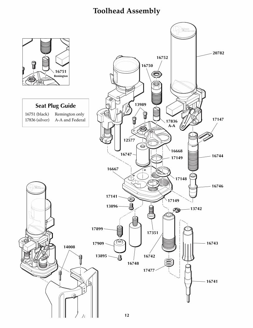
Toolhead Assembly
16741
16743
16742
17351
16748
13896
17141
16667
16747
12577
13989
17836A-A
16668
17149
17148
17149
13742
16750
1675220782
17147
16744
16746
17477
16751Remington
����
����
14008
17899
17909
13895
Seat Plug Guide16751 (black) Remington only17836 (silver) A-A and Federal
13
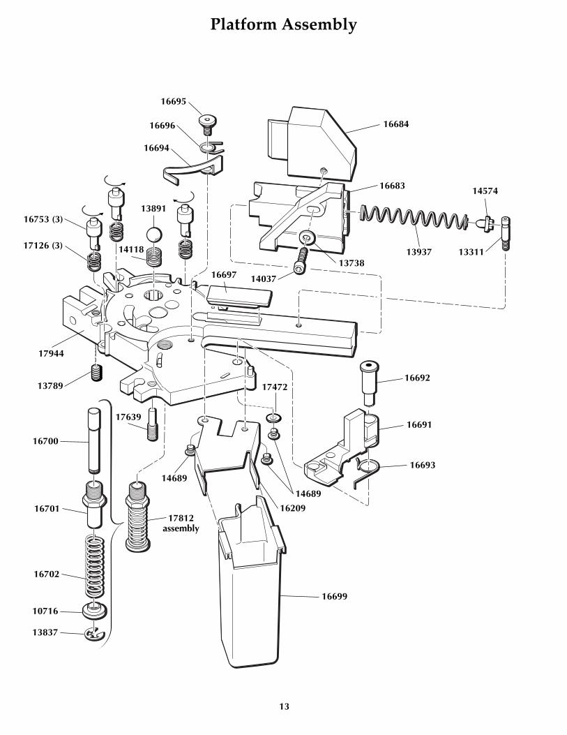
Platform Assembly
16684
16683
1393713738
1403716697
17944
13789
16700
16701
16702
17812assembly
10716
13837
17639
14574
13311
16695
16696
16694
16753 (3)
17126 (3)
13891
14118
16699
16209
14689
14689
16692
16691
16693
17472

14
Primer Feed System Assembly & Installation
������
������
������
���
�����
��
���
�����
��
14026
16717
16713
16721
16723
17601
16714
14023
17134
17354
1385617603 (3)
17474 (3)16340
14026
16710
17472
17472
17472
13773
13773
16711
14808
13923
13793
17132
14026
17472

15
Automatic Powder Measure Assembly
13882
Part # Description13652 Powder Bar Part, Large13691 Powder Measure Tube Only13793 Roller13799 Blue Wing Nut 13801 Tinnerman Nut 13845 Collar Sleeve13848 Bellcrank Bushing13853 Powder Bar Insert, Large13858 Rod Compression Spring 13871 Bellcrank Cube13882 Powder Measure Lid13893 Powder Bar Post, Large13921 Powder Measure Plug13939 Body Collar Clamp13940 Connector Body Collar13943 Powder Bar Bolt13958 Powder Bar Bolt Washer 14023 8-32 x 3/4 BHCS 14037 10-24 x 3/4 SHCS (2)14041 Bowed Washer14202 Powder Measure Tube Screws14808 Collar Roller Bushing16340 Nylon Lock Nut16731 Spring16732 Pivot Pin16734 Rod Bushing 16904 10-32x1 1/2 SHCS17140 Pin17350 Powder Bar Return Rod 17838 P/M Lock Link17839 P/M Slotted Bellcrank20063 Powder Bar Assembly, Large22273 Powder Dispenser Body
22273
13691
1379314808
13940
13845
16734
13858
1380113799
13871
1395813652
14041
13943
13893
13853
17839
14041
17350
16904
13939
14037
14023
16340
14202
14202
13921
13848
16732
17839
17838 17140
16731

16
Shot Dispenser Assembly - # 22134, 12 gauge shown
17143
17142
14026
17146
13996
13817 16739
16740
13958
16738
16726
16735
1673616737
16740
14023
13738
1480816904 13793
14041
13848
16727
13871
16733
13989
13801
13799
13858
16734
14041
13943
16725
17476
14013
13701
17573
17139
1720217138
17
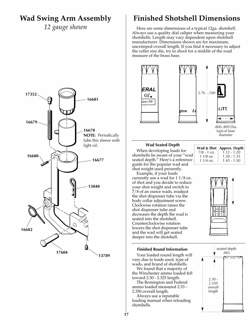
Finished Shotshell DimensionsWad Swing Arm Assembly12 gauge shown Here are some dimensions of a typical 12ga. shotshell.
Always use a quality dial caliper when measuring yourshotshells. Length may vary dependent upon shotshellmanufacturer. Dimensions shown are for maximum,uncrimped overall length. If you find it necessary to adjustthe collet size die, try to shoot for a middle of the roadmeasure of the brass base.
Wad Seated DepthWhen developing loads for
shotshells be aware of your “wadseated depth.” Here’s a referenceguide for the popular wad andshot weight used presently.
Example, if your loadscurrently use a wad for 1 1/8 oz.of shot and you decide to reduceyour shot weight and switch to7/8 of an ounce wads, readjustthe shot dispenser tube via thebody collar adjustment screw.Clockwise rotation raises theshot dispenser tube anddecreases the depth the wad isseated into the shotshell.Counterclockwise rotationlowers the shot dispenser tubeand the wad will get seateddeeper into the shotshell.
Finished Round InformationYour loaded round length will
vary due to loads used, type ofwads, and brand of shotshells.
We found that a majority ofthe Winchester ammo loaded felltoward 2.30 - 2.325 length.
The Remington and Federalammo loaded measured 2.33 -2.350 overall length.
Always use a reputableloading manual when reloadingshotshells.
.800-.809 Dia.typical base
diameter
2.76 -.100
seated depth.065
2.30 -2.350overalllength
16681
16678NOTE: Periodicallylube this sleeve withlight oil.
1667716680
13840
16682
17604
17352
16679
Wad & Shot Approx. Depth7/8 - 1 oz. 1.12 - 1.201 1/8 oz. 1.30 - 1.351 1/4 oz. 1.45 - 1.50
13789

Reloading ammunition and handling powder andprimers is inherently dangerous. Just as in shooting,accidents do happen. These accidents arenondiscriminatory; they happen to both the novice andthe experienced reloader.
We have done everything we know how to makeyour machine as safe as possible. We cannot, however,guarantee your complete safety. To minimize yourrisk, use common sense when reloading and followthese basic rules:
Never operate the machine without ear and eyeprotection on. Call our customer service department at(800) 223-4570 for information on the wide variety ofshooting/safety glasses and hearing protection thatDillon has to offer.• PAY ATTENTION: Load only when you can giveyour complete attention to the loading process.Don’t watch television or try to carry on aconversation and load at the same time. Watch theautomatic systems operate and make sure they arefunctioning properly. If you are interrupted or mustleave and come back to your loading, alwaysinspect the hulls at every station to insure that theproper operations have been completed.• SMOKING: Do not smoke while reloading or allowanyone else to smoke in your reloading area. Do notallow open flames in reloading area.• SAFETY DEVICES: Do not remove any safetydevices from your machine or modify your machine inany way.• LEAD WARNING: Be sure to have properventilation while handling lead components or whenshooting lead bullets. Lead is known to cause birthdefects, other reproductive harm and cancer. Washyour hands thoroughly after handling anything madeof lead.• LOADS AND LENGTHS: Avoid maximum loadsand pressures at all times. Use only recommendedloads from manuals and information supplied byreliable component manufacturers and suppliers. SinceDillon Precision has no control over the componentswhich may be used on their equipment, noresponsibility is implied or assumed for resultsobtained through the use of any such components.
Refer to a reliable loading manual for overall length(OAL).• QUALITY CHECKS: Every 50-100 rounds, performperiodic quality control checks on the ammunitionbeing produced. Check the amount of powder beingdropped and primer supply.• RELOADING AREA: Keep your components safelystored. Clear your work area of loose powder, primersand other flammables before loading.• COMPONENTS: Never have more than one type ofpowder in your reloading area at a time. The risk of amix-up is too great. Keep powder containers closed.
Be sure to inspect hulls prior to reloading for flaws,cracks, splits or defects. Throw these hulls away.
Keep components and ammunition out of reach ofchildren.
• WINCHESTER HULLS: Please be aware thatWinchester has redesigned the AA target hull. Thishull is no longer a one-piece extruded design. Now, itis a two-piece hull incorporating an inner reinforcingtube which extends partway up the interior of the hull.
Winchester wads have been redesigned to workwith this new design. Additionally, some aftermarketwads are now available which are compatible with theredesigned hulls. Other wads may not be compatiblewith the new AA hulls.
We suggest that you visually inspect your hulls,and load the old and new style hulls separately, usingcomponents appropriate to each style of hull.• BLACK POWDER: Do not use black powder or blackpowder substitutes in any Dillon powder measure.Loading black powder cartridges requires specializedloading equipment and techniques. Failure to do socan result in severe injury or death.• PRIMERS: Never force primers. If they get stuck inthe operation of the machine, disassemble it and gentlyremove the obstruction.
Never attempt to deprime live primers – eventuallyone will go off. When it does it will detonate the othersin the spent primer cup. Depriming live primers is thesingle most dangerous thing you can do in reloadingand can cause grave injury or death.• LOADED AMMUNITION: Properly label all of yourloaded ammunition (Date, Type of wad, primer,powder, shot charge, etc.).• BE PATIENT: Our loading equipment isconservatively rated and you should have no troubleachieving the published rates with a smooth, steadyhand. If something doesn’t seem right, stop, look andlisten. If the problem or the solution isn’t obvious, callus. The reloading bench is no place to get into a hurry.• REMEMBER: If your machine does not perform toyour expectations, or if you are having technicaldifficulties, give us a call: (800) 223-4570
GENERAL MACHINE INFORMATIONBased on our XL 650 machine frame, the SL 900
comes to you with some great automated features.Starting from the right rear of the machine, the
SL 900 features an electric casefeeder. This unitholds approximately 80 empty hulls; enough forthree boxes of shotshells.
Turn the electric casefeeder on and the shotshelldisc (#17133) will rotate until the feed tube hasfilled, then the microswitch will shut the unit off.Every stroke of the roller handle (#22183) transfersone empty hull from the feed tube to the shellplatevia the case insert slide ramp. Once a hull has beenplaced in station one of the machine, moving theroller handle (#22183) down will resize the brassbase of the hull, expand the mouth of the hull andremove the old primer. NOTE: Always examine thehulls for rocks, dirt, mud or other cases that may getstuck inside. Also look for hulls that may appearstepped on or flattened. Go ahead and squeeze them
18
MANDATORY SAFETY MEASURES
round again so they won’t get stuck in the casefeedtube (#16705). Returning the roller handle (#22183)to its full aft position will advance the hull to stationtwo, where a new primer is inserted into the hullwhen you push the roller handle (#22183) aft.
The automatic primer system holds 100 shotshellprimers. Every complete stroke of the roller handle(#22183) will feed a primer to the hull.
The automatic powder system is also located atstation two. The hopper holds one half pound ofpowder and has a fully adjustable powder bar. Theautomatic powder system is hull activated. Movethe roller handle (#22183) down. When the hullcontacts the expander/powder funnel (#16746), thepowder measure is pushed up, causing the powderbar to move and dispense one charge of powder intothe hull. Raise the roller handle (#22183) to its restposition. The powder bar will recharge and the hullwill advance to station three.
At the third station (left, front of the machine) wewill insert the wad and meter the shot into the shell.Move the roller handle (#22183) aft as if you areseating a primer into the hull. You will see the wadswing arm (#16677) tilt out, ready to accept a newwad. With every complete stroke of the roller handle(#22183), insert a new wad into the wad swing arm(#16677) when it tilts out.
Move the roller handle (#22183) down. The shotdrop tube (#16726) inserts the new wad into theempty hull and will dispense shot into the hull.Raise the roller handle (#22183) and push aft toprime. Hold the handle aft while you insert a wadinto the swing arm.
At station four we start the crimp in the top ofthe loaded hull. It is formed and folded closed,preparing the hull for the final crimp and seatingperformed in station five.
The formed, folded top of the hull will now becrimped and seated closed. This die is fullyadjustable. The crimp and seating depth can beadjusted to the desired settings.
This die also has a taper crimp feature inside thatwill form a tapered end to the hull. Again, move theroller handle (#22183) down and then back up to itsrest position. The completed shotshell advances outof the machine, down the shotshell chute (#16672)and into the Dillon bin (#17125).
STEP BY STEP PRELIMINARY ASSEMBLY1. Fasten the strong mounts (#16065) to the base
of the machine while it is lying on its side. Fig. 2
19
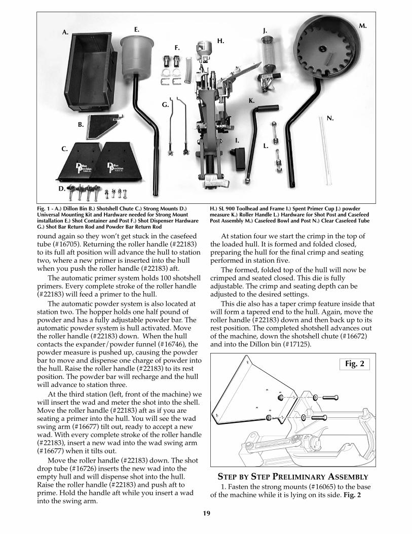
Fig. 1 - A.) Dillon Bin B.) Shotshell Chute C.) Strong Mounts D.)Universal Mounting Kit and Hardware needed for Strong Mountinstallation E.) Shot Container and Post F.) Shot Dispenser HardwareG.) Shot Bar Return Rod and Powder Bar Return Rod
H.) SL 900 Toolhead and Frame I.) Spent Primer Cup J.) powdermeasure K.) Roller Handle L.) Hardware for Shot Post and CasefeedPost Assembly M.) Casefeed Bowl and Post N.) Clear Casefeed Tube
A.
B.
C.
D.
E.
F.
G.
H.
I.
J.
K.
L.
M.
N.
Fig. 2
20
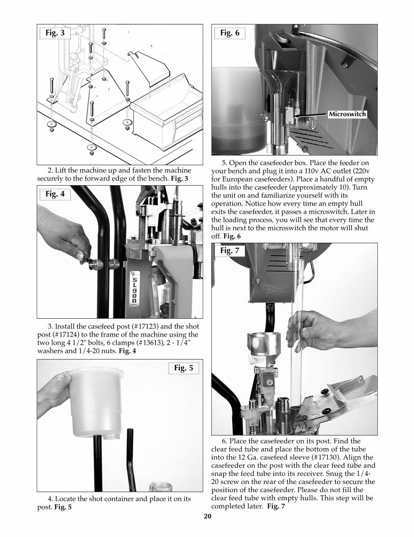
2. Lift the machine up and fasten the machinesecurely to the forward edge of the bench. Fig. 3
3. Install the casefeed post (#17123) and the shotpost (#17124) to the frame of the machine using thetwo long 4 1/2" bolts, 6 clamps (#13613), 2 - 1/4"washers and 1/4-20 nuts. Fig. 4
4. Locate the shot container and place it on itspost. Fig. 5
5. Open the casefeeder box. Place the feeder onyour bench and plug it into a 110v AC outlet (220vfor European casefeeders). Place a handful of emptyhulls into the casefeeder (approximately 10). Turnthe unit on and familiarize yourself with itsoperation. Notice how every time an empty hullexits the casefeeder, it passes a microswitch. Later inthe loading process, you will see that every time thehull is next to the microswitch the motor will shutoff. Fig. 6
6. Place the casefeeder on its post. Find theclear feed tube and place the bottom of the tubeinto the 12 Ga. casefeed sleeve (#17130). Align thecasefeeder on the post with the clear feed tube andsnap the feed tube into its receiver. Snug the 1/4-20 screw on the rear of the casefeeder to secure theposition of the casefeeder. Please do not fill theclear feed tube with empty hulls. This step will becompleted later. Fig. 7
Microswitch
Fig. 3 Fig. 6
Fig. 5
Fig. 7
Fig. 4
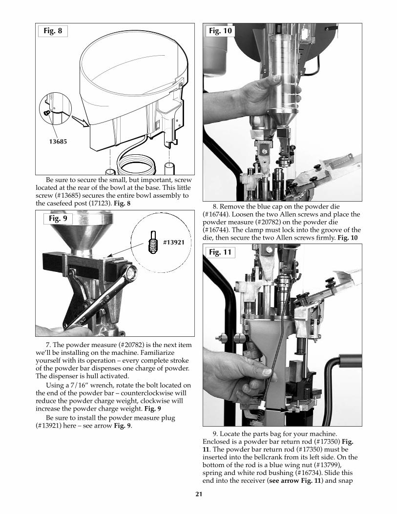
Be sure to secure the small, but important, screwlocated at the rear of the bowl at the base. This littlescrew (#13685) secures the entire bowl assembly tothe casefeed post (17123). Fig. 8
7. The powder measure (#20782) is the next itemwe’ll be installing on the machine. Familiarizeyourself with its operation – every complete strokeof the powder bar dispenses one charge of powder.The dispenser is hull activated.
Using a 7/16” wrench, rotate the bolt located onthe end of the powder bar – counterclockwise willreduce the powder charge weight, clockwise willincrease the powder charge weight. Fig. 9
Be sure to install the powder measure plug(#13921) here – see arrow Fig. 9.
8. Remove the blue cap on the powder die(#16744). Loosen the two Allen screws and place thepowder measure (#20782) on the powder die(#16744). The clamp must lock into the groove of thedie, then secure the two Allen screws firmly. Fig. 10
9. Locate the parts bag for your machine.Enclosed is a powder bar return rod (#17350) Fig.11. The powder bar return rod (#17350) must beinserted into the bellcrank from its left side. On thebottom of the rod is a blue wing nut (#13799),spring and white rod bushing (#16734). Slide thisend into the receiver (see arrow Fig. 11) and snap
21
13685
Fig. 8
Fig. 9
Fig. 10
Fig. 11#13921

the rod bushing (#16734) into the platform. Threadthe blue wing nut (#13799) “up” until there’s somespring tension against the platform – two to threeturns. Do not fill the powder measure (#20782) atthis time. This will be completed later.
10. Next we move to station three where the wadis seated and the shot is dispensed. The Dillon shotdispenser works similar to the powder measure(#20782). The shot dispenser is activated by the hullat this station. No hull – no shot. Every completestroke of the shot bar dispenses one charge of shot.To adjust, loosen the bolt set screw (#16740) 1/4 of aturn. Then use a 7/16” wrench to rotate the boltlocated on the end of the shot bar (#16738) –counterclockwise will reduce the shot weight andclockwise will increase the shot weight. Fig. 12
11. To complete the assembly of the shotdispenser tube, you’ll need the following itemsfrom the parts bag: shot bar return rod (#16733),clear shot feed tube, two shot dispenser fittings(#17139), two shot fitting e-clips (#17202) and twotube clamps. Fig. 13
12. Assemble the shot dispenser fittings to theclear shot feed tube. Fig. 14 Place the tube clampsloosely on the tube. Slide one end of the shotdispenser fitting into the bottom of the shot hopper(#16724 item A Fig. 13) and lock it in using one ofthe shot fitting e-clips. Now, align the completeassembly and install the other shot dispenserfitting and e-clip into the dispenser top (#17142)and tighten the clamps. Fig. 15
22
Fig. 12
Fig. 14
Fig. 15
Fig. 13
A
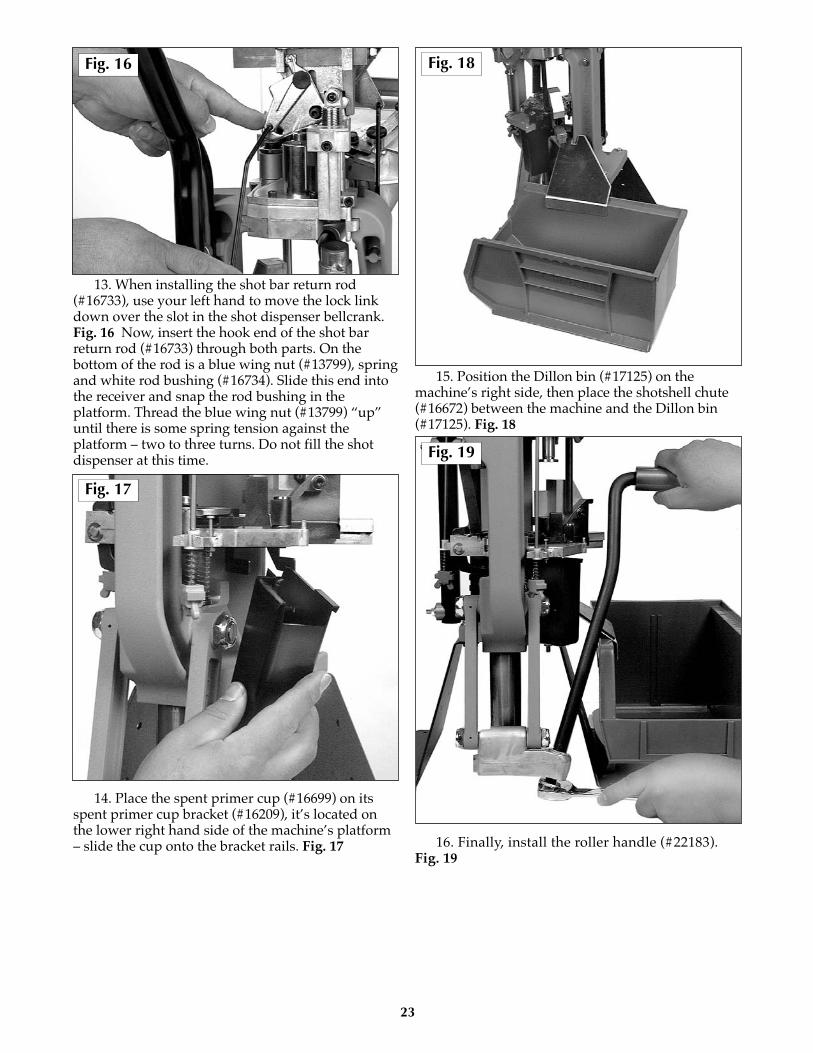
13. When installing the shot bar return rod(#16733), use your left hand to move the lock linkdown over the slot in the shot dispenser bellcrank.Fig. 16 Now, insert the hook end of the shot barreturn rod (#16733) through both parts. On thebottom of the rod is a blue wing nut (#13799), springand white rod bushing (#16734). Slide this end intothe receiver and snap the rod bushing in theplatform. Thread the blue wing nut (#13799) “up”until there is some spring tension against theplatform – two to three turns. Do not fill the shotdispenser at this time.
14. Place the spent primer cup (#16699) on itsspent primer cup bracket (#16209), it’s located onthe lower right hand side of the machine’s platform– slide the cup onto the bracket rails. Fig. 17
15. Position the Dillon bin (#17125) on themachine’s right side, then place the shotshell chute(#16672) between the machine and the Dillon bin(#17125). Fig. 18
16. Finally, install the roller handle (#22183).Fig. 19
23
Fig. 17
Fig. 19
Fig. 18Fig. 16

The SL 900 shotshell machine has beenassembled and tested using Winchester AA hulls. Asample is included with the machine.
Station One – The collet sizer is adjusted forresizing the brass base. Fig. 20
Station Two – Inside the powder die (#16744)you’ll find the powder funnel Fig 21. This partuniforms the top of the shotshell hull and dispensesone charge of powder into the hull. The powder barwill need to be adjusted to the desired powderweight. Its important to use a quality powder scaleto do this. Fig 21A
The powder die has been adjusted to a height sothat the powder measure bellcrank can make fullstrokes when activated. Fig 21B. Turning thepowder die (#16744) counterclockwise will raise thepowder system, reducing the amount of stroke thebellcrank has. Fig 21C.
Station Three – Two operations occur hereinvolving wad and shot insertion.
In the wad swing arm (#16677) we’ve installed acaliber specific wad guide (#16681). Fig. 22
24
Fig. 21
Fig. 20
Fig. 21B
Fig. 21C
Complete Stroke
Incomplete Stroke
Fig. 22
FACTORY SETTINGS
Fig. 21A
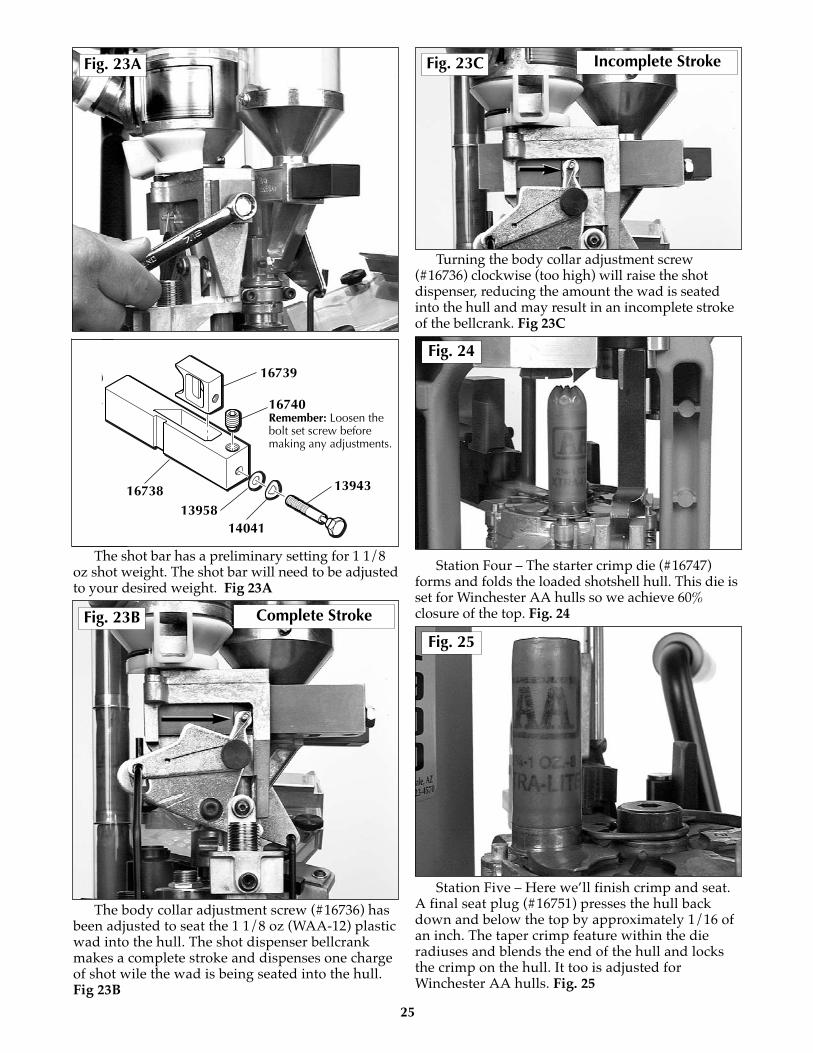
The shot bar has a preliminary setting for 1 1/8oz shot weight. The shot bar will need to be adjustedto your desired weight. Fig 23A
The body collar adjustment screw (#16736) hasbeen adjusted to seat the 1 1/8 oz (WAA-12) plasticwad into the hull. The shot dispenser bellcrankmakes a complete stroke and dispenses one chargeof shot wile the wad is being seated into the hull.Fig 23B
Turning the body collar adjustment screw(#16736) clockwise (too high) will raise the shotdispenser, reducing the amount the wad is seatedinto the hull and may result in an incomplete strokeof the bellcrank. Fig 23C
Station Four – The starter crimp die (#16747)forms and folds the loaded shotshell hull. This die isset for Winchester AA hulls so we achieve 60%closure of the top. Fig. 24
Station Five – Here we’ll finish crimp and seat.A final seat plug (#16751) presses the hull backdown and below the top by approximately 1/16 ofan inch. The taper crimp feature within the dieradiuses and blends the end of the hull and locksthe crimp on the hull. It too is adjusted forWinchester AA hulls. Fig. 25
25
Fig. 25
Fig. 24
Fig. 23A
Fig. 23B
Fig. 23C
Complete Stroke
Incomplete Stroke
16739
16740Remember: Loosen thebolt set screw beforemaking any adjustments.
1395816738
14041
13943
Before you charge ahead and begin tossingcomponents into your new SL 900 shotshellmachine, there is a routine we’d like you to follow.
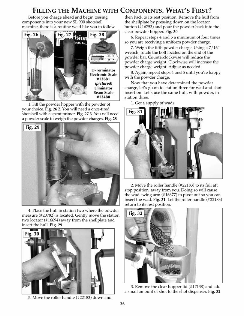
1. Fill the powder hopper with the powder ofyour choice. Fig. 26 2. You will need a once-firedshotshell with a spent primer. Fig. 27 3. You will needa powder scale to weigh the powder charges. Fig. 28
4. Place the hull in station two where the powdermeasure (#20782) is located. Gently move the stationtwo locator (#16694) away from the shellplate andinsert the hull. Fig. 29
5. Move the roller handle (#22183) down and
then back to its rest position. Remove the hull fromthe shellplate by pressing down on the locatorbutton (#16753) and pour the powder back into theclear powder hopper. Fig. 30
6. Repeat steps 4 and 5 a minimum of four timesso you are receiving a uniform powder charge.
7. Weigh the fifth powder charge. Using a 7/16”wrench, rotate the bolt located on the end of thepowder bar. Counterclockwise will reduce thepowder charge weight. Clockwise will increase thepowder charge weight. Adjust as needed.
8. Again, repeat steps 4 and 5 until you’re happywith the powder charge.
Now that you have determined the powdercharge, let’s go on to station three for wad and shotinsertion. Let’s use the same hull, with powder, instation three.
1. Get a supply of wads.
2. Move the roller handle (#22183) to its full aftstop position, away from you. Doing so will causethe wad swing arm (#16677) to pivot out so you caninsert the wad. Fig. 31 Let the roller handle (#22183)return to its rest position.
3. Remove the clear hopper lid (#17138) and adda small amount of shot to the shot dispenser. Fig. 32
26
D-TerminatorElectronic Scale
#13681(pictured)Eliminator Beam Scale
#13480
Fig. 29
Fig. 31
Fig. 32
Fig. 26 Fig. 27 Fig. 28
Fig. 30
FILLING THE MACHINE WITH COMPONENTS. WHAT’S FIRST?

4. Move the roller handle (#22183) down andthen back up to its rest position. Remove the hullfrom the machine by pressing down on the locatorbutton (#16753) and pour the shot back into the shotdispenser. Fig. 33
5. Place the hull back into station three and againmove the roller handle (#22183) down and thenback to its rest position. Remove the hull and weighthe shot charge. Fig. 34
6. Loosen the bolt set screw (#16740) 1/4 of aturn. Then using a 7/16” wrench, rotate the boltlocated on the end of the shot bar (#16738).Counterclock- wise turns will reduce the shot chargeweight. Clockwise turns will increase the shotcharge weight. Adjust as needed. NOTE: Its alwayseasier to make adjustments when the bar is emptyand in the forward drop position.
7. Again, repeat steps 4 and 5 until you’re happywith the shot charge. Remember to place the clearhopper lid (#17138) back onto the shot dispenser &tighten the bolt set screw (#16740).
Now that you have determined the shot charge,let’s move on to station four and five where thestarter crimp die (#16747) and final seat/crimpfunctions are performed. Let’s use the same hull(with shot).
1. Place the hull (with shot) into station four.
2. Move the roller handle (#22183) down andthen back to its rest position. The formed and foldedhull has just completed station four and hasadvanced to station five. Fig. 35
3. Once again, move the roller handle (#22183)down. As you return to the rest position, you’ll seethe completed round advance and move out of themachine. The completed round will fall down theshotshell chute (#16672) and land in the Dillon bin(#17125). Fig. 36
Review the dummy round you’ve just made.Let’s go ahead and make one more dummy round.Please note, when making these dummy rounds, westart at station two and then go through all theremaining stations on the machine. This is theintroductory process. Next we’ll be adding empty,fired hulls and new primers.
27
Fig. 36
Fig. 35
Fig. 34
Fig. 33
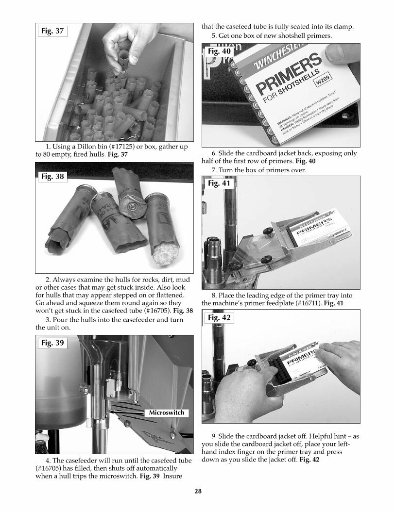
1. Using a Dillon bin (#17125) or box, gather upto 80 empty, fired hulls. Fig. 37
2. Always examine the hulls for rocks, dirt, mudor other cases that may get stuck inside. Also lookfor hulls that may appear stepped on or flattened.Go ahead and squeeze them round again so theywon’t get stuck in the casefeed tube (#16705). Fig. 38
3. Pour the hulls into the casefeeder and turnthe unit on.
4. The casefeeder will run until the casefeed tube(#16705) has filled, then shuts off automaticallywhen a hull trips the microswitch. Fig. 39 Insure
that the casefeed tube is fully seated into its clamp.5. Get one box of new shotshell primers.
6. Slide the cardboard jacket back, exposing onlyhalf of the first row of primers. Fig. 40
7. Turn the box of primers over.
8. Place the leading edge of the primer tray intothe machine’s primer feedplate (#16711). Fig. 41
9. Slide the cardboard jacket off. Helpful hint – asyou slide the cardboard jacket off, place your left-hand index finger on the primer tray and pressdown as you slide the jacket off. Fig. 42
28
Fig. 37
Fig. 38Fig. 41
Fig. 42
Microswitch
Fig. 40
Fig. 39
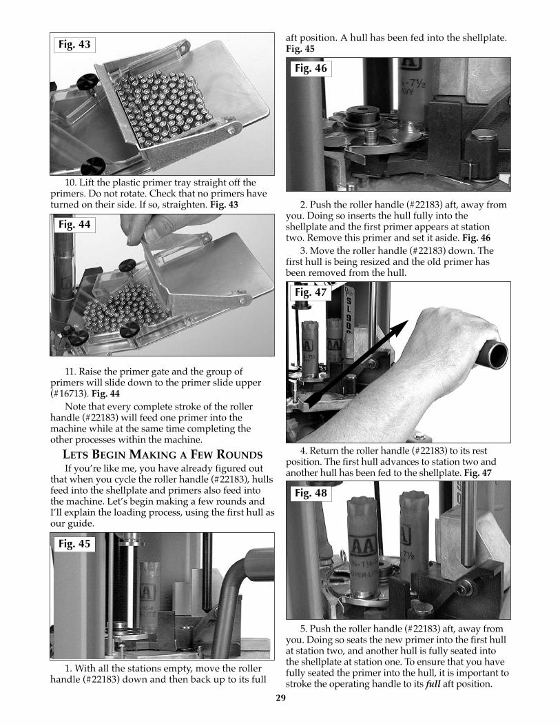
10. Lift the plastic primer tray straight off theprimers. Do not rotate. Check that no primers haveturned on their side. If so, straighten. Fig. 43
11. Raise the primer gate and the group ofprimers will slide down to the primer slide upper(#16713). Fig. 44
Note that every complete stroke of the rollerhandle (#22183) will feed one primer into themachine while at the same time completing theother processes within the machine.
LETS BEGIN MAKING A FEW ROUNDSIf you’re like me, you have already figured out
that when you cycle the roller handle (#22183), hullsfeed into the shellplate and primers also feed intothe machine. Let’s begin making a few rounds andI’ll explain the loading process, using the first hull asour guide.
1. With all the stations empty, move the rollerhandle (#22183) down and then back up to its full
aft position. A hull has been fed into the shellplate.Fig. 45
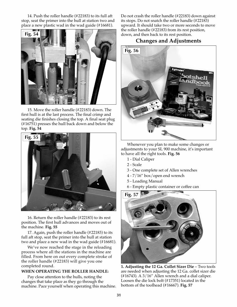
2. Push the roller handle (#22183) aft, away fromyou. Doing so inserts the hull fully into theshellplate and the first primer appears at stationtwo. Remove this primer and set it aside. Fig. 46
3. Move the roller handle (#22183) down. Thefirst hull is being resized and the old primer hasbeen removed from the hull.
4. Return the roller handle (#22183) to its restposition. The first hull advances to station two andanother hull has been fed to the shellplate. Fig. 47
5. Push the roller handle (#22183) aft, away fromyou. Doing so seats the new primer into the first hullat station two, and another hull is fully seated intothe shellplate at station one. To ensure that you havefully seated the primer into the hull, it is important tostroke the operating handle to its full aft position.
29
Fig. 47
Fig. 48
Fig. 45
Fig. 46
Fig. 44
Fig. 43

With experience, you will acquire the “feel” of theprimer being seated fully. Fig. 48
6. Move the roller handle (#22183) down. The firsthull is getting a charge of powder at station two.
7. Return the roller handle (#22183) to its restposition. The first hull advances to station three,another fired hull is fed to the shellplate and the hullat station two is ready to receive a new primer. Fig. 49
8. Push the roller handle (#22183) to its full aftstop and hold as (using your left hand) you pick upa plastic wad and place it into the wad guide(#16681). This same aft stroke seated the new primerinto the hull at station two and the hull at stationone is fully seated into the shellplate. Release theroller handle (#22183). Fig. 50
9. Move the roller handle (#22183) down. Thefirst hull is at station three, where a new plastic wad
is seated. It then receives a charge of shot. Again, thehulls in station one and station two are beingprocessed as well. Fig. 51
10. Raise the roller handle (#22183) to its full aftstop. The first hull advances to station four and theother hulls advance as well. Fig. 52 If you encounterresistance, STOP! Do not force the handle. Theremay be something blocking the primer transfer arm.See the troubleshooting section for instructions onhow to proceed.
11. Push the roller handle (#22183) aft to seat theprimer into the hull at station two and place a newplastic wad in the wad guide (#16681).
Special note: An important step in the loading process– remember when pushing the roller handle (#22183) aftto seat the new shotshell primer, you must also place anew plastic wad into the wad guide (#16681) at the sametime. See Fig. 50
12. Move the roller handle (#22183) down. Thefirst hull is being formed and folded with the startercrimp die (#16747) at station four.
13. Return the roller handle (#22183) to its full aftposition. All the hulls advance one station. The firsthull is now in station five. Fig. 53
30
Fig. 52
Fig. 53
Fig. 49
Fig. 50
Fig. 51
14. Push the roller handle (#22183) to its full aftstop, seat the primer into the hull at station two andplace a new plastic wad in the wad guide (#16681).
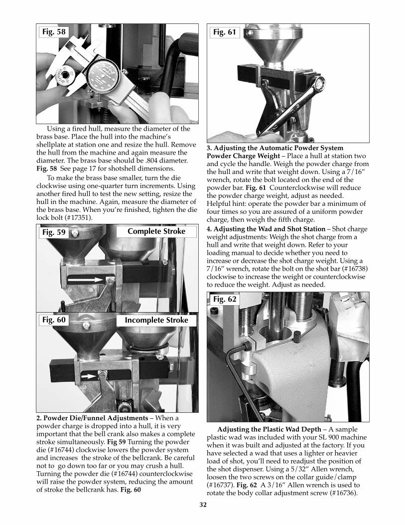
15. Move the roller handle (#22183) down. Thefirst hull is at the last process. The final crimp andseating die finishes closing the top. A final seat plug(#16751) presses the hull back down and below thetop. Fig. 54
16. Return the roller handle (#22183) to its restposition. The first hull advances and moves out ofthe machine. Fig. 55
17. Again, push the roller handle (#22183) to itsfull aft stop, seat the primer into the hull at stationtwo and place a new wad in the wad guide (#16681).
We’ve now reached the stage in the reloadingprocess where all the stations in the machine arefilled. From here on out every complete stroke ofthe roller handle (#22183) will give you onecompleted round.WHEN OPERATING THE ROLLER HANDLE:
Pay close attention to the hulls, noting thechanges that take place as they go through themachine. Pace yourself when operating this machine.
Do not crash the roller handle (#22183) down againstits stops. Do not snatch the roller handle (#22183)upward. It should take two or more seconds to movethe roller handle (#22183) from its rest position,down, and then back to its rest position.
Changes and Adjustments
Whenever you plan to make some changes oradjustments to your SL 900 machine, it’s importantto have all the right tools. Fig. 56
1 - Dial Caliper2 - Scale3 - One complete set of Allen wrenches4 - 7/16” box/open end wrench5 - Loading Manual6 - Empty plastic container or coffee can
1. Adjusting the 12 Ga. Collet Sizer Die – Two toolsare needed when adjusting the 12 Ga. collet sizer die(#16743). A 3/16” Allen wrench and a dial caliper.Loosen the die lock bolt (#17351) located in thebottom of the toolhead (#16667). Fig. 57
31
Fig. 56
Fig. 57
Fig. 54
Fig. 55
Using a fired hull, measure the diameter of thebrass base. Place the hull into the machine’sshellplate at station one and resize the hull. Removethe hull from the machine and again measure thediameter. The brass base should be .804 diameter.Fig. 58 See page 17 for shotshell dimensions.
To make the brass base smaller, turn the dieclockwise using one-quarter turn increments. Usinganother fired hull to test the new setting, resize thehull in the machine. Again, measure the diameter ofthe brass base. When you’re finished, tighten the dielock bolt (#17351).
2. Powder Die/Funnel Adjustments – When apowder charge is dropped into a hull, it is veryimportant that the bell crank also makes a completestroke simultaneously. Fig 59 Turning the powderdie (#16744) clockwise lowers the powder systemand increases the stroke of the bellcrank. Be carefulnot to go down too far or you may crush a hull.Turning the powder die (#16744) counterclockwisewill raise the powder system, reducing the amountof stroke the bellcrank has. Fig. 60
3. Adjusting the Automatic Powder SystemPowder Charge Weight – Place a hull at station twoand cycle the handle. Weigh the powder charge fromthe hull and write that weight down. Using a 7/16”wrench, rotate the bolt located on the end of thepowder bar. Fig. 61 Counterclockwise will reducethe powder charge weight, adjust as needed.Helpful hint: operate the powder bar a minimum offour times so you are assured of a uniform powdercharge, then weigh the fifth charge.4. Adjusting the Wad and Shot Station – Shot chargeweight adjustments: Weigh the shot charge from ahull and write that weight down. Refer to yourloading manual to decide whether you need toincrease or decrease the shot charge weight. Using a7/16” wrench, rotate the bolt on the shot bar (#16738)clockwise to increase the weight or counterclockwiseto reduce the weight. Adjust as needed.
Adjusting the Plastic Wad Depth – A sampleplastic wad was included with your SL 900 machinewhen it was built and adjusted at the factory. If youhave selected a wad that uses a lighter or heavierload of shot, you’ll need to readjust the position ofthe shot dispenser. Using a 5/32” Allen wrench,loosen the two screws on the collar guide/clamp(#16737). Fig. 62 A 3/16” Allen wrench is used torotate the body collar adjustment screw (#16736).
32
Fig. 62
Fig. 61Fig. 58
Fig. 59 Complete Stroke
Fig. 60 Incomplete Stroke

When reloading with light shot load plasticwads it may be necessary to adjust the shotdispenser position. Rotate the body collaradjustment screw (#16736) clockwise to raise theshot dispenser. Tighten all the collar screws, thentest the changes. Fig. 63
When reloading with heavy shot load plasticwads it may be necessary to adjust the shotdispenser position. Rotate the body collaradjustment screw (#16736) counterclockwise tolower the shot dispenser. Tighten all the screws, thentest the changes.5. Adjusting the starter crimp Die – This die hasbeen adjusted at the factory using Winchester AAhulls. If you have another brand of hull you’d like toreload, it may be necessary to readjust this die. Testrun a hull through the machine to decide if anychanges are needed.
What we like to see is a 60% closure of the top,formed and folded. This is important so that stationfive’s final crimp/seat can produce a uniform foldedcrimp. Fig. 64
We found that when we reloaded Remingtonhulls and wads, we would need to adjust the startercrimp die (#16747) down. The heavier walledRemington hulls appear to be somewhat moreresistant to being formed and folded. Turn thestarter crimp die (#16747) down approximately one-half turn clockwise as needed.
Reloading with Federal hulls and wads requiresa little readjusting as well. Raise the starter crimpdie (#16747) approximately one-half turn counter-clockwise. This will help produce a uniform foldedcrimp/seat.
Winchester hulls and Versatile wads loaded fineand required little or no adjustment at all.Remington hulls and Versatile wads also loadedfine. Remington hulls and Figure 8 wads requireadjustment. The stiffer style Figure 8 wad needs tobe compressed; do so by lowering the wad seateddepth 1 to 2 full turns (as detailed under step 4 ofChanges and Adjustments). Also, reducing the shotcharge weight may be necessary when using thiswad. Follow the above changes with a readjustmentof the starter crimp die (#16747), turn the die downapproximately one-half turn clockwise as needed (asdetailed under step 5 of Changes and Adjustments).6. Adjusting the final crimp Die – Two adjustmentsare available here on the final crimp die. Example, ifsome of the reloads you have just finished appearshallow as shown on page 17, then turn the seatplug clockwise (down), using 1/4 turn increments.
Or, you can turn the whole die clockwise (down)using 1/4 turn increments. You will then see thenext reload with more taper on its end and theseated depth will be deeper.
Another example relating to the final crimp dieadjustment when reloading different shotshells:“When I have made some reloads, some of theshotshells have buckled in the middle, but it doesn’thappen all the time.” You will need to raise thewhole die by turning the assembly counterclockwise(up) at least 1/4 to 1/2 a turn.
Removing the Shot from the Machine: When it’s time to switch to another shot size,
place a plastic container or coffee can next to theshot dispenser drain. Rotate the plastic shot drainwith your index finger and hold it there until all theshot has emptied. Any remaining shot in the shotbar (#16738) and dispenser can be removed byrunning a hull through the machine. Fig. 65
33
Fig. 65
Fig. 63
Fig. 64

Example: you’ve just finished making somerounds using #9 lead shot, the next size you’ll beusing is #7 1/2 lead shot. Remember to alwaysweigh the shot charge when doing this switch.Please use a quality scale. Fig. 66Removing the Toolhead:
One of the great features on a Dillon machine isthe removable toolhead (#16667). The removabletoolhead (#16667) allows you to convert from onehull brand to another hull brand or another caliberin a matter of minutes. Let’s use the following stepsto remove and install a toolhead (#16667) on the SL900 machine.
1. Empty all the shot from the shot hopper(#16724) and clear tube via the shot drain.
2. Remove the shot fitting e-clip and the shotfitting from the shot dispenser top (#17142). Fig. 67
3. Remove the shot bar return rod (#16733).Fig. 68
4. Remove the powder bar return rod (#17350).Fig. 69
5. Remove the two toolhead pins (#14008)located on the front and rear of the toolhead andframe. Fig. 70
6. Slide the toolhead assembly out of the machineand set it aside.
34
Fig. 68
Fig. 69
Fig. 70
Fig. 67
Fig. 66

7. Pick up your other toolhead (#16667) and slideit onto the frame.
8. Insert the two toolhead pins (#14008) into theholes located on the front and rear of the frame.
9. Install the powder bar return rod (#17350).10. Install the shot bar return rod (#16733).11. Attach the shot fitting to the shot dispenser
top (#17142).12. Install the shot fitting e-clip.You’ve now completed the toolhead swap – the
only step that remains is refilling the components(powder and shot) and you’re ready to go again.
SHELLPLATE REMOVALWhen you service your SL 900 machine –
cleaning, lubing, or switching to another caliber –please follow these steps to remove the shellplate.
1. Remove the ejector wire (#16676). Using a small,flat blade screwdriver, hook it beneath the ejector wire(#16676) and lift upward to remove it. Fig. 71
2. Move the roller handle (#22183) halfway downits stroke.
3. Use a 1/8” Allen wrench to loosen the 1/4-28brass tip set screw (#13923) located on the left side
of the machine, below the platform, in the mainshaft(#13485). Fig. 72
4. Return the roller handle (#22183) to its restposition.
5. Use a 1/4” Allen wrench to unscrew theshellplate bolt (#13418).
6. Remove the shellplate from the machine. Fig.73 Be careful not to lose the 3/8” index ball (#13891) andindex pawl (#13667) when cleaning and lubing yourmachine. Fig. 74 When you install your shellplate ontothe machine, remember to wipe a light amount of greasein the center hole of the shellplate.
7. Reinstall the shellplate.
35
Fig. 73
Fig. 74
Fig. 71
Fig. 72
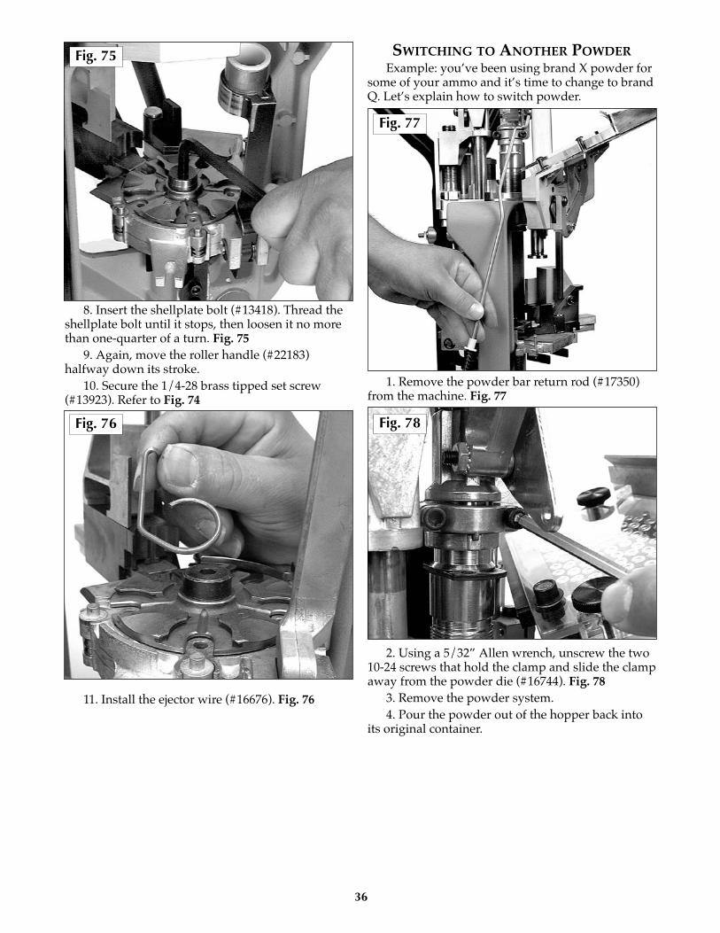
8. Insert the shellplate bolt (#13418). Thread theshellplate bolt until it stops, then loosen it no morethan one-quarter of a turn. Fig. 75
9. Again, move the roller handle (#22183)halfway down its stroke.
10. Secure the 1/4-28 brass tipped set screw(#13923). Refer to Fig. 74
11. Install the ejector wire (#16676). Fig. 76
SWITCHING TO ANOTHER POWDERExample: you’ve been using brand X powder for
some of your ammo and it’s time to change to brandQ. Let’s explain how to switch powder.
1. Remove the powder bar return rod (#17350)from the machine. Fig. 77
2. Using a 5/32” Allen wrench, unscrew the two10-24 screws that hold the clamp and slide the clampaway from the powder die (#16744). Fig. 78
3. Remove the powder system.4. Pour the powder out of the hopper back into
its original container.
36
Fig. 77
Fig. 78
Fig. 75
Fig. 76

5. Turn the powder system upright and positionthe unit over the opening of the powder containerand cycle the powder bar with your thumb. Fig. 79
6. Once the powder system is completely empty,reinstall the powder system and tighten the two 10-24 screws using a 5/32” Allen wrench.
7. Reattach the powder bar return rod (#17350).8. Refill the powder hopper with the new
powder.9. Please use a quality powder scale to determine
the new powder charge weight.
The Primer System:The primer feed system on the SL 900 machine is
a fully mechanical system. Every complete stroke ofthe roller handle (#22183) will feed a new shotshellprimer into the machine. Fig. 80 Two veryimportant but simple points:
#1. Always keep the machine and its primer feedsystem clean and free of dirt. Do not place any oilsor grease on the primer feed plate. This hinders thefree flowing operation of the system.
#2. Never allow excess powder or dirt to buildup on the deck where the primer transfer arm(#16691) swings in and out of the machine.
If you decide to service your machine or don’twish to have any primers feeding, install the “stopblock” into the primer system as shown. Whenyou’re ready to resume, simply remove the “stopblock” and the primers will begin feeding again thenext time you cycle the handle.
37
Fig. 79 Fig. 81
Fig. 80

38
A 28 gauge conversion package (#22139),includes the following items:
1.) A complete toolhead assembly with diesinstalled; Station 1, collet sizer & depriming pinassembly. Station 2, powder die with 28 gaugepowder funnel and retaining clip. Station 3,complete shot dispenser assembly with 1/2 oz – 1.0oz shot bar and 28 gauge shot drop tube. Station 4,starter crimp star/radius form insert. Station 5, newspring/over floating taper crimp die.
2.) A 28 gauge conversion kit box containing:(a) one 28 gauge shellplate (#10625), (b) threelocator buttons (#16753) with locator rings(#10602) and springs (#17126), (c) one greenstation 2 locator insert (#10624), (d) two green wadguides (1 spare, #10620), (e) one 28 gauge casefeedsleeve assembly (#22129). Fig. 1
CONVERTING THE MACHINEThe following is a step by step routine to use for
converting your machine to reload other gauges.Refer to your SL 900 reloading manual as needed.
1. Drain the shot via the shot dispenser drain.Hint, use an old coffee can, widemouth water jug orshot bag to catch the shot.
2. Disconnect the return rods on both the shotand powder dispensers.
3. Remove the shot fitting e-clip on the shotdispenser and slide the fitting out of thedispenser housing.
4. Remove the two black toolhead pins andremove the toolhead from the machine.
5. Install the red flag block into the primer feedassembly. Fig. 2
REPLACING THE SHELLPLATE AND PARTSIN THE PLATFORM
1. Remove the ejector wire (#16676).2. Move the roller handle to the down position.3. Use a 1/8" Allen wrench to loosen the 1/4-28
brass tip set screw 1/2 a turn. The brass tip set screwis located on the left side of the machine, below theplatform, in the mainshaft.
4. While the machine is in this configuration, it isa good time to exchange the red wad guide (12gauge) with the green wad guide (28 gauge). Fig. 3
28 Gauge Conversion Instructions
Fig. 1
Fig. 3
Fig. 2
a
toolheadassembly
b (3)c
de
39
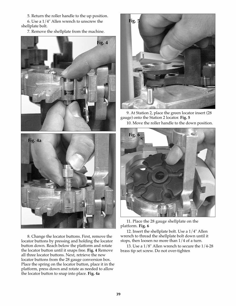
5. Return the roller handle to the up position.6. Use a 1/4" Allen wrench to unscrew the
shellplate bolt.7. Remove the shellplate from the machine.
8. Change the locator buttons. First, remove thelocator buttons by pressing and holding the locatorbutton down. Reach below the platform and rotatethe locator button until it snaps free. Fig. 4 Removeall three locator buttons. Next, retrieve the newlocator buttons from the 28 gauge conversion box.Place the spring on the locator button, place it in theplatform, press down and rotate as needed to allowthe locator button to snap into place. Fig. 4a
9. At Station 2, place the green locator insert (28gauge) onto the Station 2 locator. Fig. 5
10. Move the roller handle to the down position.
11. Place the 28 gauge shellplate on theplatform. Fig. 6
12. Insert the shellplate bolt. Use a 1/4" Allenwrench to thread the shellplate bolt down until itstops, then loosen no more than 1/4 of a turn.
13. Use a 1/8" Allen wrench to secure the 1/4-28brass tip set screw. Do not over-tighten
Fig. 6
Fig. 5
Fig. 4a
Fig. 4
40
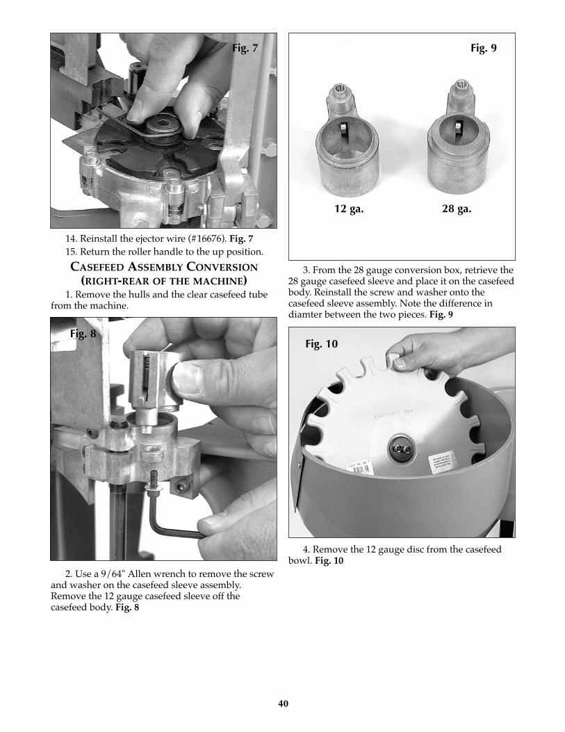
14. Reinstall the ejector wire (#16676). Fig. 715. Return the roller handle to the up position.
CASEFEED ASSEMBLY CONVERSION(RIGHT-REAR OF THE MACHINE)
1. Remove the hulls and the clear casefeed tubefrom the machine.
2. Use a 9/64" Allen wrench to remove the screwand washer on the casefeed sleeve assembly.Remove the 12 gauge casefeed sleeve off thecasefeed body. Fig. 8
3. From the 28 gauge conversion box, retrieve the28 gauge casefeed sleeve and place it on the casefeedbody. Reinstall the screw and washer onto thecasefeed sleeve assembly. Note the difference indiamter between the two pieces. Fig. 9
4. Remove the 12 gauge disc from the casefeedbowl. Fig. 10
Fig. 10
Fig. 9
Fig. 8
Fig. 7
12 ga. 28 ga.

41
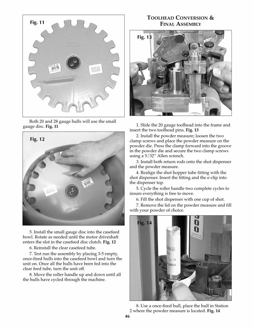
Both 20 and 28 gauge hulls use the small gaugedisc. Fig. 11
5. Install the small gauge disc into the casefeedbowl. Rotate as needed until the motor driveshaftenters the slot in the casefeed disc clutch. Fig. 12
6. Reinstall the clear casefeed tube.7. Test run the assembly by placing 3-5 empty,
once-fired hulls into the casefeed bowl and turn theunit on. Once all the hulls have been fed into theclear feed tube, turn the unit off.
8. Move the roller handle up and down until allthe hulls have cycled through the machine.
TOOLHEAD CONVERSION &FINAL ASSEMBLY
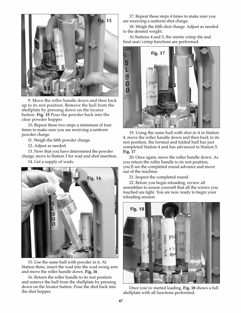
1. Slide the 28 gauge toolhead into the frame andinsert the two toolhead pins. Fig. 13
2. Install the powder measure; loosen the twoclamp screws and place the powder measure on thepowder die. Press the clamp forward into the groovein the powder die and secure the two clamp screwsusing a 5/32” Allen wrench.
3. Install both return rods onto the shot dispenserand the powder measure.
4. Realign the shot hopper tube fitting with theshot dispenser. Insert the fitting and the e-clip intothe dispenser top.
5. Cycle the roller handle two complete cycles toinsure everything is free to move.
6. Fill the shot dispenser with one cup of shot.7. Remove the lid on the powder measure and fill
with your powder of choice.
8. Use a once-fired hull, place the hull in Station2 where the powder measure is located. Fig. 14
Fig. 14
Fig. 13
Fig. 12
Fig. 11
42
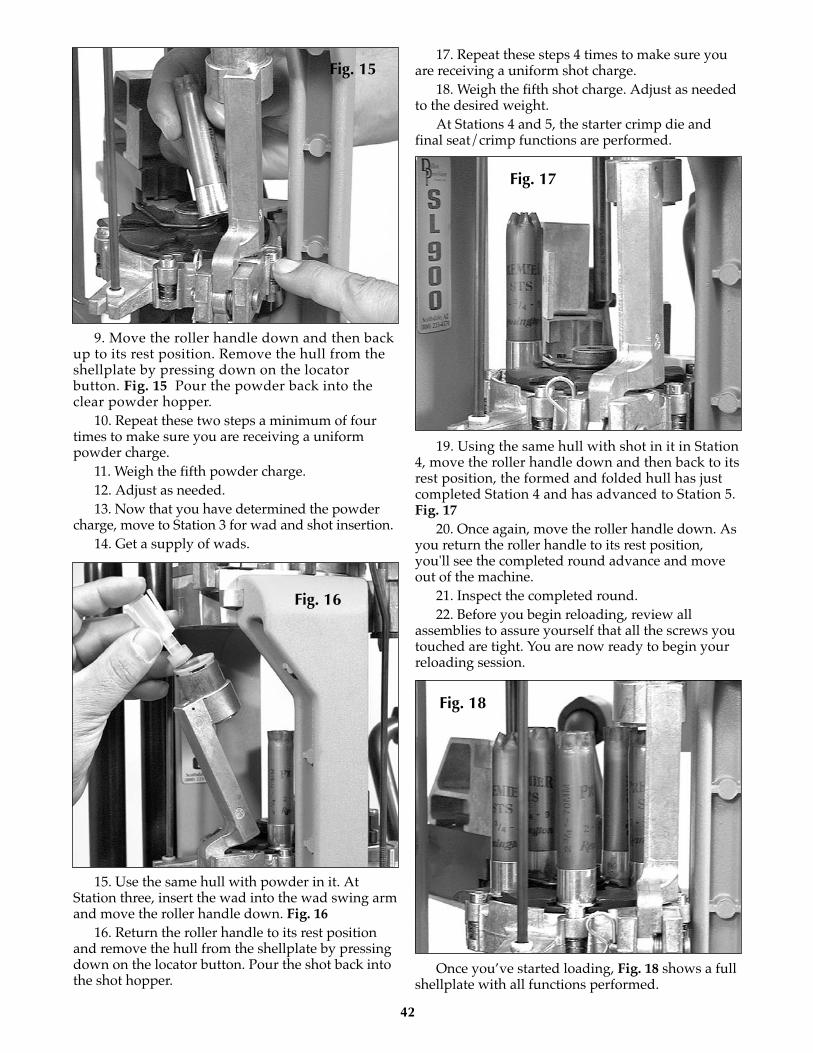
9. Move the roller handle down and then backup to its rest position. Remove the hull from theshellplate by pressing down on the locatorbutton. Fig. 15 Pour the powder back into theclear powder hopper.
10. Repeat these two steps a minimum of fourtimes to make sure you are receiving a uniformpowder charge.
11. Weigh the fifth powder charge.12. Adjust as needed.13. Now that you have determined the powder
charge, move to Station 3 for wad and shot insertion.14. Get a supply of wads.
15. Use the same hull with powder in it. AtStation three, insert the wad into the wad swing armand move the roller handle down. Fig. 16
16. Return the roller handle to its rest positionand remove the hull from the shellplate by pressingdown on the locator button. Pour the shot back intothe shot hopper.
17. Repeat these steps 4 times to make sure youare receiving a uniform shot charge.
18. Weigh the fifth shot charge. Adjust as neededto the desired weight.
At Stations 4 and 5, the starter crimp die andfinal seat/crimp functions are performed.
19. Using the same hull with shot in it in Station4, move the roller handle down and then back to itsrest position, the formed and folded hull has justcompleted Station 4 and has advanced to Station 5.Fig. 17
20. Once again, move the roller handle down. Asyou return the roller handle to its rest position,you'll see the completed round advance and moveout of the machine.
21. Inspect the completed round. 22. Before you begin reloading, review all
assemblies to assure yourself that all the screws youtouched are tight. You are now ready to begin yourreloading session.
Once you’ve started loading, Fig. 18 shows a fullshellplate with all functions performed.
Fig. 18
Fig. 17
Fig. 16
Fig. 15

43
A 20 gauge conversion package (#22138),includes the following items:
1.) A complete toolhead assembly with diesinstalled; Station 1, collet sizer & depriming pinassembly. Station 2, powder die with 20 gaugepowder funnel and retaining clip. Station 3,complete shot dispenser assembly with 1/2 oz – 1.0oz shot bar and 20 gauge shot drop tube. Station 4,starter crimp star/radius form insert. Station 5, newspring/over floating taper crimp die.
2.) A 20 gauge conversion kit box containing:(a) one 20 gauge shellplate (#10612), (b) threelocator buttons (#16753) with locator rings(#10602) and springs (#17126), (c) one yellowstation 2 locator insert (#10603), (d) two yellowwad guides (1 spare - #10610), (e) one 20 gaugecasefeed sleeve assembly (#22128). Fig. 1
CONVERTING THE MACHINEThe following is a step by step routine to use for
converting your machine to reload other gauges.Refer to your SL 900 reloading manual as needed.
1. Drain the shot via the shot dispenser drain.Hint, use an old coffee can, widemouth water jug orshot bag to catch the shot.
2. Disconnect the return rods on both the shotand powder dispensers.
3. Remove the shot fitting e-clip on the shotdispenser and slide the fitting out of the dispenserhousing.
4. Remove the two black toolhead pins andremove the toolhead from the machine.
5. Install the red flag block into the primer feedassembly. Fig. 2
REPLACING THE SHELLPLATE AND PARTSIN THE PLATFORM
1. Remove the ejector wire (#16676).2. Move the roller handle to the down position.3. Use a 1/8" Allen wrench to loosen the 1/4-28
brass tip set screw 1/2 a turn. The brass tip set screwis located on the left side of the machine, below theplatform, in the mainshaft.
4. While the machine is in this configuration, it isa good time to exchange the red wad guide (12gauge) with the yellow wad guide (20 gauge). Fig. 3
20 Gauge Conversion Instructions
Fig. 1
Fig. 3
d
toolheadassembly
b (3)a
c
e
Fig. 2

44
5. Return the roller handle to the up position.6. Use a 1/4" Allen wrench to unscrew the
shellplate bolt.7. Remove the shellplate from the machine.
8. Change the locator buttons. First, remove thelocator buttons by pressing and holding the locatorbutton down. Reach below the platform and rotatethe locator button until it snaps free. Fig. 4 Removeall three locator buttons. Next, retrieve the newlocator buttons from the 20 gauge conversion box.Place the spring on the locator button, place it in theplatform, press down and rotate as needed to allowthe locator button to snap into place. Fig. 4a
9. At Station 2, place the yellow locator insert (20gauge) onto the Station 2 locator. Fig. 5
10. Move the roller handle to the down position.
11. Place the 20 gauge shellplate on theplatform. Fig. 6
12. Insert the shellplate bolt. Use a 1/4" Allenwrench to thread the shellplate bolt down until itstops, then loosen no more than 1/4 of a turn.
13. Use a 1/8" Allen wrench to secure the 1/4-28brass tip set screw. Do not over-tighten
Fig. 6
Fig. 5
Fig. 4a
Fig. 4
45
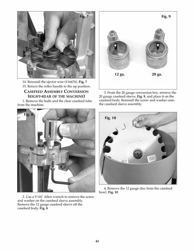
14. Reinstall the ejector wire (#16676). Fig. 715. Return the roller handle to the up position.
CASEFEED ASSEMBLY CONVERSION(RIGHT-REAR OF THE MACHINE)
1. Remove the hulls and the clear casefeed tubefrom the machine.
2. Use a 9/64" Allen wrench to remove the screwand washer on the casefeed sleeve assembly.Remove the 12 gauge casefeed sleeve off thecasefeed body. Fig. 8
3. From the 20 gauge conversion box, retrieve the20 gauge casefeed sleeve, Fig. 9, and place it on thecasefeed body. Reinstall the screw and washer ontothe casefeed sleeve assembly.
4. Remove the 12 gauge disc from the casefeedbowl. Fig. 10
Fig. 10
Fig. 9
Fig. 8
Fig. 7
12 ga. 20 ga.
46
Both 20 and 28 gauge hulls will use the smallgauge disc. Fig. 11
5. Install the small gauge disc into the casefeedbowl. Rotate as needed until the motor driveshaftenters the slot in the casefeed disc clutch. Fig. 12
6. Reinstall the clear casefeed tube.7. Test run the assembly by placing 3-5 empty,
once-fired hulls into the casefeed bowl and turn theunit on. Once all the hulls have been fed into theclear feed tube, turn the unit off.
8. Move the roller handle up and down until allthe hulls have cycled through the machine.
TOOLHEAD CONVERSION &FINAL ASSEMBLY
1. Slide the 20 gauge toolhead into the frame andinsert the two toolhead pins. Fig. 13
2. Install the powder measure; loosen the twoclamp screws and place the powder measure on thepowder die. Press the clamp forward into the groovein the powder die and secure the two clamp screwsusing a 5/32” Allen wrench.
3. Install both return rods onto the shot dispenserand the powder measure.
4. Realign the shot hopper tube fitting with theshot dispenser. Insert the fitting and the e-clip intothe dispenser top.
5. Cycle the roller handle two complete cycles toinsure everything is free to move.
6. Fill the shot dispenser with one cup of shot.7. Remove the lid on the powder measure and fill
with your powder of choice.
8. Use a once-fired hull, place the hull in Station2 where the powder measure is located. Fig. 14
Fig. 14
Fig. 13
Fig. 12
Fig. 11
47
9. Move the roller handle down and then backup to its rest position. Remove the hull from theshellplate by pressing down on the locatorbutton. Fig. 15 Pour the powder back into theclear powder hopper.
10. Repeat these two steps a minimum of fourtimes to make sure you are receiving a uniformpowder charge.
11. Weigh the fifth powder charge.12. Adjust as needed.13. Now that you have determined the powder
charge, move to Station 3 for wad and shot insertion.14. Get a supply of wads.
15. Use the same hull with powder in it. AtStation three, insert the wad into the wad swing armand move the roller handle down. Fig. 16
16. Return the roller handle to its rest positionand remove the hull from the shellplate by pressingdown on the locator button. Pour the shot back intothe shot hopper.
17. Repeat these steps 4 times to make sure youare receiving a uniform shot charge.
18. Weigh the fifth shot charge. Adjust as neededto the desired weight.
At Stations 4 and 5, the starter crimp die andfinal seat/crimp functions are performed.
19. Using the same hull with shot in it in Station4, move the roller handle down and then back to itsrest position, the formed and folded hull has justcompleted Station 4 and has advanced to Station 5.Fig. 17
20. Once again, move the roller handle down. Asyou return the roller handle to its rest position,you'll see the completed round advance and moveout of the machine.
21. Inspect the completed round. 22. Before you begin reloading, review all
assemblies to assure yourself that all the screws youtouched are tight. You are now ready to begin yourreloading session.
Once you’ve started loading, Fig. 18 shows a fullshellplate with all functions performed.
Fig. 18
Fig. 17
Fig. 16
Fig. 15

Troubleshooting Section #1, Primer System1. I broke my primer transfer arm (#16691). This
happens when a new primer is only partially seatedinto the shotshell. A spare is included with themachine, but it’s important that you makecomplete, full strokes of the operating handlewhen using the SL 900. See Illustrations 1 & 2
2. A primer is laying sideways inside the clear coverof the primer tray. How do I remove it? ShotshellPrimers are magnetic – get a small magnet, screw-driver or pointer and use it to get that primer out.
Another method available is to simply unscrewthe black knobs that secure the cover, slide the clearcover off, and remove all the primers. Reassemblethe parts, then refill the primer tray with primers.
3. From time to time I notice that a new primer landson the platform rather than into the hole in the primertransfer arm. Why? Two things may be occurringhere: First, the speed in which you operate thehandle affects the feeding of new primers. As thenew primer is dispensed from the primer tray, ittakes a fraction of a second to fall through the tubeand into the hole in the primer transfer arm. Whenyou reach the bottom of the handle’s stroke, pausefor a second, then move the handle again. Alwayspace yourself when operating your machine.
Second, you always get a new primer with everycomplete stroke of the machine’s handle. If thereisn’t a shotshell in station two to receive the primer,that primer will be left on the platform.
4. A dirty primer tray can be annoying. If youreload in a dusty environment (for instance, a barnor garage) or the shotshells you have are dirty, overtime dust will collect on the primer tray. We've madethe primer tray stainless steel so you can clean itwith windex or alcohol. Just remove the clear coverand wipe it clean. Our machine cover was designedto help keep your loader clean when you're notusing it. Ask for part #13329.
5. Where does the grease go again? See page 37 inthe manual, also make sure your hands are grease-free when handling new primers; they don't feedwell in any machine when they’re greasy.
6. How do I stop the primers from feeding? Arectangular insert has been included with themachine. Place your thumb on the primer drop tubeand raise the primer system by pushing it up. Insertthe stop block BETWEEN the primer feed body andthe tray mounting bracket. Remove the stop blockwhen you're ready to begin reloading again.
7. When I operate the machine, it doesn’t always dropa primer. An adjustment screw (#17639, see theschematic on page 13) is located in the platform.This screw increases or reduces the stroke of theblack primer slide located on the primer tray via theprimer drop tube. If the primer moves over the holebut it does not drop thru, turn the adjustment screwcounterclockwise to raise the primer drop tube and
the black primer slide will stroke more and then theprimer will drop thru the hole.
The adjustment screw (#17639) may periodicallygo out of adjustment. Remove the screw and cleanthe threads and the hole in the platform withalcohol. Apply some blue Loctite to the threads andreinstall.
8. Why do I get high primers when using Winchesterprimers and Remington hulls, but not when usingRemington hulls and primers? The new silver coloredWinchester primers appear to be .002 diameterlarger than the previous copper colored primers atthe point just above the flange. We suggest using abit more forward push on the operating handlewhen seating the primer or switching to Remingtonprimers for Remington hulls.
Illustrations 1 & 2Inside your parts bag you will find an extra
primer transfer arm, #16691, see illustration 1.While every effort has been made to manufacture asound machine for you, it’s important that youmake complete, full strokes of the operatinghandle when using the SL 900. Assure yourselfthat the primer is fully seated into the shotshell.We’ve found that the primer transfer arm WILLbreak if the primer is only partially seated into theshotshell. Never force the handle when a jamoccurs, instead, slowly return the handle to its restposition. When the shotshells appear out of thebottom of the dies, remove the suspect shotshellfrom the priming station. Once you have removedthe suspect shotshell, complete the stroke of thehandle you started.
48
SNAP!
Illustration 1Primer Transfer Arm
Illustration 2Primer Transfer Arm
Troubleshooting
49
Technical Support1-800-223-4570
Troubleshooting Section #2, Casefeeder1. General casefeeder information: Capacity is
80 shotshells. Electric motor information: 110V ACfor US customers and 220V AC (3 RPM) forEuropean customers.
2. The shotshells jam in the clear funnel. Alwayscheck the shotshells to make sure that no flattenedor stepped on shotshells get into the casefeeder.Suggestion: Use the clear feed tube to gage anyshotshell to make sure that it can slide through thetube before placing it in the casefeeder bowl.
3. It looks like half of a shotshell is hanging out of thebottom of the casefeed body. A shotshell can jam in thecasefeed body if the mouth of the shotshell is sodeformed that it gets stuck on the casefeed phishinside the casefeed body. Simply remove theshotshell by pulling it out.
4. I have noticed that the microswitch does not shutthe motor off. The microswitch uses the pressure ofthe shotshell against the aluminum arm on theswitch to turn the motor off. You can bend thealuminum arm as needed to assure that the switchis activated.
Troubleshooting Section #3, General1. It’s important that you make complete, full
strokes of the operating handle when using theSL 900.
2. Never use any solvent-type lubricants suchas Brakefree or WD-40. These will cause themainshaft to seize in the main bore.
3. When I operate the machine, some shotshells getstuck and strike the mouth of the sizing die. Theshotshells may have a deformed rim or base. Throwthe bad shotshells away.
Another possible cause is that a shot pellet mayhave fallen into the pocket area, stopping theshotshell from feeding in to the shellplate. Inspectthe shellplate grooves for any smashed shot orother debris.
4. The operating handle stopped halfway through itsstroke. The first thing to do when this occurs is to tapevery shotshell. See if you can feel which one is in abind. It may be that the primer is not fully seatedinto the shotshell. It’s important that you makecomplete, full strokes of the operating handlewhen using the SL 900.
It may be that the first shotshell has struck themouth of the sizing die, or a wad or smaller gauge
shotshell is stuck inside the first shotshell and hasjammed itself onto the depriming pin. Or it may bethat a wad has not entered the shotshell properlyand is caught on the mouth of the shotshell.
Whatever the cause, remove the suspect roundby lowering the shotshells out of the dies, thenremove the problem round from the machine.
5. I’m not sure if the powder charge is correct.Always use a reputable loading manual. The powderbar does not come set from the factory. You must usea scale to adjust the weight of the powder chargebeing dispensed. The machine manual has detailedinstructions on how to set up the powder measure.
6. When I use the machine some of the wad petals getcaught and fold beneath the shot tube. Then a spillmight occur because the shot is too high in theshotshell. Always inspect the wads before you placethem into the wad seater. You can use your thumb topress the petals open, then insert the wad into thewad seater.
7. How do I remove that last amount of shot fromthe shot bar? When all the shot has been drainedout of the large hopper, place a plastic container orcoffee can next to the shot dispenser drain. Rotatethe plastic shot drain with your index finger andhold it there until all the shot has emptied. Anyremaining shot in the shot bar (#16738) anddispenser can be removed by running a hull throughthe machine.
8. When I cycle the handle the wad swing arm hits theedge of the toolhead as it tries to go thru the hole. Wehave placed an adjustment set screw below the footof the wad swing arm inside the platform (#13789,see the schematic on page 10). Using a 1/8” Allenwrench turn the screw as needed to center the wadswing arm in the hole it passes thru in the toolhead.
9. The shot dispenser and the powder systemsuse a 10-32 thread kep nut (#13817). These nuts maybecome loose over time and should be replaced withNylock nuts (#13841).
10. The shot dispensing tube (#17479) isdesigned to flex during operation. Do not shortenthe tube for any reason or it will no longer funtionas it was designed to.
NOTE: All electrical/electronic components inDillon equipment are covered by a one yearwarranty.

50
Fig. 83 - Left view.Fig. 82 - Right view.
H.
N.
M.
L.
N.
P.
O.
J.
E.
I.
N.
F.
D.
G.
C.
A.
K.
C.
B.
A.) Mainshaft: The most important lube point ofall. Use 30w motor oil to lube the mainshaft(#13485).Use grease on the following items:B.) Mainshaft Pivot Pin (#13830)C.) Link Arm Cross Pins (one hole in the frameand two in the crank)D.) Shellplate Bolt HoleE.) Case Insert Slide Arm/RampF.) Wad SleeveG.) Wad Swing Arm Pivot Hole
H.) Powder Body Collar (rails, hole and roller,bellcrank)I.) Lock Link (#16730)J.) Around the Collet Sizer Sleeve (#16742)K.) On the Ring Indexer and Indexer BlockL.) A very light amount on the surface of thePrimer Drop TubeM.) Primer Feed Body RailsN.) The Main Pivot Hole in all BellcranksO.) Primer Feed Cam (#16717), Cam SlotP.) 1/4” Diameter Alignment Post
LUBE POINTS ON THE SL 900 MACHINE: FIG. 82 & FIG. 83
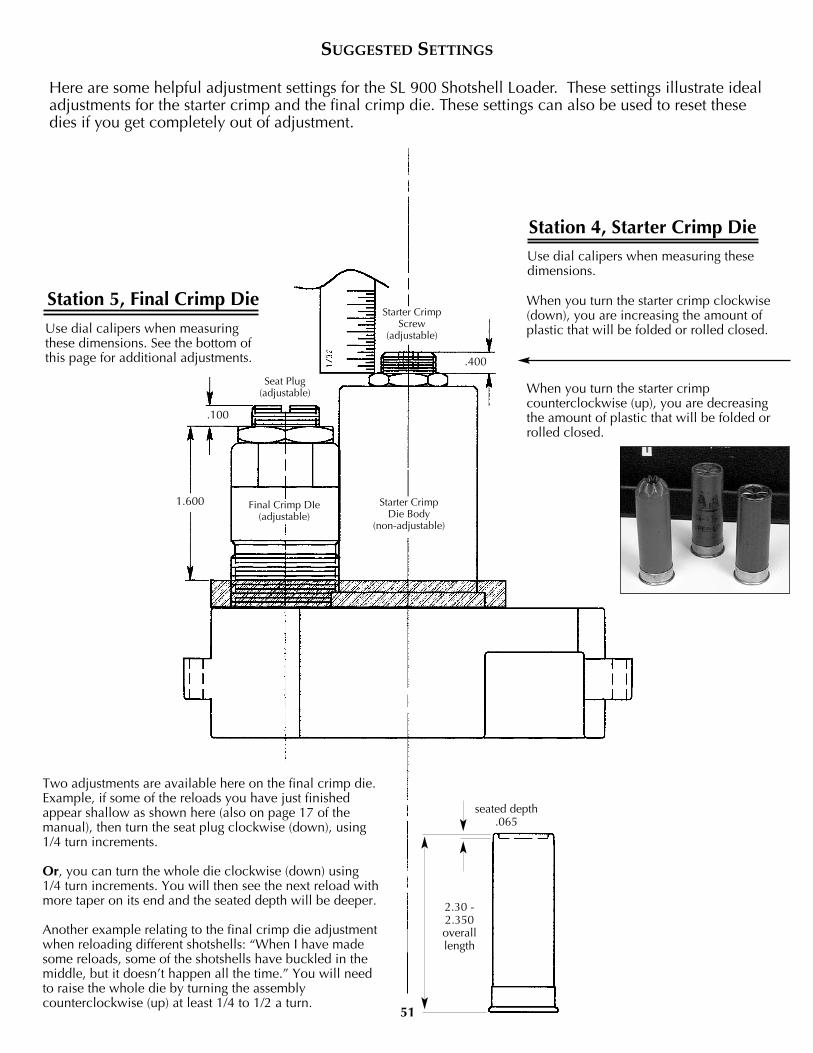
Two adjustments are available here on the final crimp die.Example, if some of the reloads you have just finishedappear shallow as shown here (also on page 17 of themanual), then turn the seat plug clockwise (down), using1/4 turn increments.
Or, you can turn the whole die clockwise (down) using1/4 turn increments. You will then see the next reload withmore taper on its end and the seated depth will be deeper.
Another example relating to the final crimp die adjustmentwhen reloading different shotshells: “When I have madesome reloads, some of the shotshells have buckled in themiddle, but it doesn’t happen all the time.” You will needto raise the whole die by turning the assemblycounterclockwise (up) at least 1/4 to 1/2 a turn.
Here are some helpful adjustment settings for the SL 900 Shotshell Loader. These settings illustrate idealadjustments for the starter crimp and the final crimp die. These settings can also be used to reset thesedies if you get completely out of adjustment.
Station 5, Final Crimp DieUse dial calipers when measuringthese dimensions. See the bottom ofthis page for additional adjustments.
Use dial calipers when measuring thesedimensions.
When you turn the starter crimp clockwise(down), you are increasing the amount ofplastic that will be folded or rolled closed.
When you turn the starter crimpcounterclockwise (up), you are decreasingthe amount of plastic that will be folded orrolled closed.
Station 4, Starter Crimp Die
2.30 -2.350overalllength
seated depth.065
Starter CrimpScrew
(adjustable)
Final Crimp DIe(adjustable)
Seat Plug(adjustable)
.100
1.600
.400
Starter CrimpDie Body
(non-adjustable)
SUGGESTED SETTINGS
51
