1747-6.21, slc 500 fixed hardware style installation and ... · installation and operation manual...
TRANSCRIPT
Installation andOperation Manual
SLC 500 FixedHardware Style
(Cat. No. 1747L20, 1747L30,and 1747L40 Processors)
AllenBradley
product icon

Installation andOperation Manual
SLC 500 FixedHardware Style
(Cat. No. 1747-L20, 1747-L30,and 1747-L40 Processors)
Allen-Bradley

Solid state equipment has operational characteristics differing from those ofelectromechanical equipment. “Safety Guidelines for the Application,Installation and Maintenance of Solid State Controls” (Publication SGI-1.1)describes some important differences between solid state equipment andhard–wired electromechanical devices. Because of this difference, and alsobecause of the wide variety of uses for solid state equipment, all personsresponsible for applying this equipment must satisfy themselves that eachintended application of this equipment is acceptable.
In no event will the Allen-Bradley Company be responsible or liable forindirect or consequential damages resulting from the use or application ofthis equipment.
The examples and diagrams in this manual are included solely for illustrativepurposes. Because of the many variables and requirements associated withany particular installation, the Allen-Bradley Company cannot assumeresponsibility or liability for actual use based on the examples and diagrams.
No patent liability is assumed by Allen-Bradley Company with respect to useof information, circuits, equipment, or software described in this manual.
Reproduction of the contents of this manual, in whole or in part, withoutwritten permission of the Allen-Bradley Company is prohibited.
Throughout this manual we use notes to make you aware of safetyconsiderations.
!ATTENTION: Identifies information about practices orcircumstances that can lead to personal injury or death, propertydamage, or economic loss.
Attentions help you:
• identify a hazard• avoid the hazard• recognize the consequences
Important: Identifies information that is especially important for successfulapplication and understanding of the product.
PLC and PLC 5 are registered trademarks of Allen-Bradley Company, Inc.SLC, SLC 500, Dataliner, and DTAM are trademarks of Allen-Bradley Company, Inc.IBM is a registered trademark of International Business Machines, Incorporated.Tandy is a trademark of the Tandy Corporation.Gateway 2000 is a trademark of Gateway 2000, Inc.Toshiba is a trademark of Toshiba America, Inc.Compaq is a registered trademark of Compaq Computer Corporation.Deskpro is a trademark of Compaq Computer Corporation.
Important User Information

Summary of Changes
Summary of Changes
The information below summarizes the changes to this manual since the lastprinting as 1747-NI001 in November, 1993.
To help you find new information and updated information in this release ofthe manual, we have included change bars as shown to the right of thisparagraph.
The table below lists sections that document new features and additionalinformation about existing features, and shows where to find this newinformation.
For This New Information See
Updated list of related publications Preface
High voltage warning Chapters 2, 4, and 7
New Information

Summary of Changes i. . . . . . . . . . . . . . . . . . . . . . . . . . . .
New Information i. . . . . . . . . . . . . . . . . . . . . . . . . . . . . . . . . . . . .
Preface P-1. . . . . . . . . . . . . . . . . . . . . . . . . . . . . . . . . . . . . . .
Who Should Use this Manual P-1. . . . . . . . . . . . . . . . . . . . . . . . . . . How to Use this Manual P-2. . . . . . . . . . . . . . . . . . . . . . . . . . . . . . . Related Publications P-3. . . . . . . . . . . . . . . . . . . . . . . . . . . . . . . . . . Related Publications P-3. . . . . . . . . . . . . . . . . . . . . . . . . . . . . . . . . . Conventions Used in this Manual P-4. . . . . . . . . . . . . . . . . . . . . . . . . Allen-Bradley Support P-4. . . . . . . . . . . . . . . . . . . . . . . . . . . . . . . .
Local Product Support P-4. . . . . . . . . . . . . . . . . . . . . . . . . . . . . . Technical Product Assistance P-4. . . . . . . . . . . . . . . . . . . . . . . . . Your Questions or Comments on this Manual P-4. . . . . . . . . . . . . .
Selecting Your Hardware Components 1-1. . . . . . . . . . . . . . .
What Your SLC 500 Controller Can Do for You 1-1. . . . . . . . . . . . . . . Overview of Your Fixed Control System 1-2. . . . . . . . . . . . . . . . . . . . Fixed Controller Specifications 1-3. . . . . . . . . . . . . . . . . . . . . . . . . .
Memory Backup for the SLC 500 Fixed Controller 1-4. . . . . . . . . . . Configuration Options 1-5. . . . . . . . . . . . . . . . . . . . . . . . . . . . . . . Input Specifications 1-6. . . . . . . . . . . . . . . . . . . . . . . . . . . . . . . . Output Specifications 1-7. . . . . . . . . . . . . . . . . . . . . . . . . . . . . . . Relay Contact Ratings 1-8. . . . . . . . . . . . . . . . . . . . . . . . . . . . . .
Selecting the 2-Slot Chassis 1-8. . . . . . . . . . . . . . . . . . . . . . . . . . . . Selecting Discrete I/O Modules 1-8. . . . . . . . . . . . . . . . . . . . . . . . . . Selecting Speciality I/O Modules 1-8. . . . . . . . . . . . . . . . . . . . . . . . . Selecting Enclosures 1-9. . . . . . . . . . . . . . . . . . . . . . . . . . . . . . . . . Selecting Operator Interfaces 1-9. . . . . . . . . . . . . . . . . . . . . . . . . . .
Programming with a Hand-Held Terminal (1747-PT1) 1-9. . . . . . . . Programming with Advanced Programming Software (APS)
on an IBM Compatible Computer 1-9. . . . . . . . . . . . . . . . . . . . Advanced Programming Software, 1747-PA2E 1-10. . . . . . . . . . . DH-485 Interface Converter (1747-PIC) 1-10. . . . . . . . . . . . . . .
Monitoring with a Data Table Access Module (1747-DTAM-E) 1-10. . EEPROM and UVPROM Memory Modules 1-11. . . . . . . . . . . . . . . . . . Selecting Isolation Transformers 1-12. . . . . . . . . . . . . . . . . . . . . . . . . Special Considerations 1-13. . . . . . . . . . . . . . . . . . . . . . . . . . . . . . . .
Excessive Line Voltage Variations 1-13. . . . . . . . . . . . . . . . . . . . . . Excessive Noise 1-13. . . . . . . . . . . . . . . . . . . . . . . . . . . . . . . . . . Selecting Surge Suppressors 1-14. . . . . . . . . . . . . . . . . . . . . . . . . Selecting Contact Protection 1-16. . . . . . . . . . . . . . . . . . . . . . . . . . Transistor Output Transient Pulses 1-17. . . . . . . . . . . . . . . . . . . . .
Table of Contents

Table of Contentsii
Example 1-19. . . . . . . . . . . . . . . . . . . . . . . . . . . . . . . . . . . . . .
System Installation Recommendations 2-1. . . . . . . . . . . . . . .
Typical Installation 2-1. . . . . . . . . . . . . . . . . . . . . . . . . . . . . . . . . . . Spacing Your Components 2-2. . . . . . . . . . . . . . . . . . . . . . . . . . . . . Preventing Excessive Heat 2-2. . . . . . . . . . . . . . . . . . . . . . . . . . . . . Grounding Guidelines 2-3. . . . . . . . . . . . . . . . . . . . . . . . . . . . . . . . . Master Control Relay 2-5. . . . . . . . . . . . . . . . . . . . . . . . . . . . . . . . .
Emergency-Stop Switches 2-6. . . . . . . . . . . . . . . . . . . . . . . . . . . Power Considerations 2-7. . . . . . . . . . . . . . . . . . . . . . . . . . . . . . . .
Common Power Source 2-7. . . . . . . . . . . . . . . . . . . . . . . . . . . . . Loss of Power Source 2-7. . . . . . . . . . . . . . . . . . . . . . . . . . . . . . Input States on Power Down 2-7. . . . . . . . . . . . . . . . . . . . . . . . . . Other Types of Line Conditions 2-7. . . . . . . . . . . . . . . . . . . . . . . .
Safety Considerations 2-8. . . . . . . . . . . . . . . . . . . . . . . . . . . . . . . . High Voltages - SLC 500 Fixed Hardware Style Controller (Series C)
(Applies to 1747-L20A, -L30A, -L40A, -L20C, -L30C, and -L40Ccontrollers) 2-8. . . . . . . . . . . . . . . . . . . . . . . . . . . . . . . . . . . .
Disconnecting Main Power 2-8. . . . . . . . . . . . . . . . . . . . . . . . . . . Wiring Safety Circuits 2-9. . . . . . . . . . . . . . . . . . . . . . . . . . . . . . . Distributing Power 2-9. . . . . . . . . . . . . . . . . . . . . . . . . . . . . . . . . Testing the Master Control Relay Circuit 2-9. . . . . . . . . . . . . . . . . .
Preventive Maintenance 2-9. . . . . . . . . . . . . . . . . . . . . . . . . . . . . . .
Mounting Your SLC 500 Control System 3-1. . . . . . . . . . . . . .
Mounting Fixed Hardware Style Units 3-1. . . . . . . . . . . . . . . . . . . . . . 20 I/O Fixed ControllerÀ 3-2. . . . . . . . . . . . . . . . . . . . . . . . . . . . . 30 and 40 I/O Fixed ControllerÀ 3-3. . . . . . . . . . . . . . . . . . . . . . . . 2-Slot Expansion ChassisÀ 3-4. . . . . . . . . . . . . . . . . . . . . . . . . . Link Coupler (AIC)À 3-5. . . . . . . . . . . . . . . . . . . . . . . . . . . . . . . . Data Table Access Module (DTAM)À 3-5. . . . . . . . . . . . . . . . . . . .
Installing Your Hardware Components 4-1. . . . . . . . . . . . . . . .
Mounting the 2-Slot Expansion Chassis 4-1. . . . . . . . . . . . . . . . . . . . Installing I/O and Speciality Modules 4-2. . . . . . . . . . . . . . . . . . . . . . Installing Your Memory Module 4-4. . . . . . . . . . . . . . . . . . . . . . . . . .
Removing Your Memory Module 4-5. . . . . . . . . . . . . . . . . . . . . . . Using the High-Speed Counter 4-5. . . . . . . . . . . . . . . . . . . . . . . . . .
High-Speed Counter Operation 4-5. . . . . . . . . . . . . . . . . . . . . . . . High-Speed Counter Input Compatibility 4-6. . . . . . . . . . . . . . . . . Wiring Diagram of a High-Speed Counter Sinking Input Circuit 4-7. Wiring Diagram of a High-Speed Counter Sourcing Input Circuit 4-7
Table of Contents iii
Wiring Your Control System 5-1. . . . . . . . . . . . . . . . . . . . . . . .
Defining Sinking and Sourcing 5-1. . . . . . . . . . . . . . . . . . . . . . . . . . . Contact Output Circuits AC or DC 5-2. . . . . . . . . . . . . . . . . . . . Solid-State DC I/O Circuits 5-2. . . . . . . . . . . . . . . . . . . . . . . . . . . Sourcing Device with Sinking Input Module Circuit 5-2. . . . . . . . . . . Sinking Device with Sourcing Input Module Circuit 5-3. . . . . . . . . . . Sinking Device with Sourcing Output Module Circuit 5-3. . . . . . . . . Sourcing Device with Sinking Output Module Circuit 5-3. . . . . . . . .
Preparing Your Wiring Layout 5-4. . . . . . . . . . . . . . . . . . . . . . . . . . . Features of an I/O Module 5-5. . . . . . . . . . . . . . . . . . . . . . . . . . . . . . Recommendations for Wiring I/O Devices 5-6. . . . . . . . . . . . . . . . . . . Wiring Your I/O Modules 5-7. . . . . . . . . . . . . . . . . . . . . . . . . . . . . . . Using Removable Terminal Blocks (RTBs) 5-8. . . . . . . . . . . . . . . . . .
Removing RTBs 5-8. . . . . . . . . . . . . . . . . . . . . . . . . . . . . . . . . . . Installing RTBs 5-9. . . . . . . . . . . . . . . . . . . . . . . . . . . . . . . . . . . .
Starting Up Your Control System 6-1. . . . . . . . . . . . . . . . . . . .
Procedures for Starting Up the Control System 6-1. . . . . . . . . . . . . . . 1. Inspect Your Installation 6-2. . . . . . . . . . . . . . . . . . . . . . . . . . . . . 2. Disconnect Motion-causing Devices 6-2. . . . . . . . . . . . . . . . . . . . 3. Initialize and Test Your Processor 6-3. . . . . . . . . . . . . . . . . . . . . . 4. Test Your Inputs 6-4. . . . . . . . . . . . . . . . . . . . . . . . . . . . . . . . . . .
Input Troubleshooting Steps 6-5. . . . . . . . . . . . . . . . . . . . . . . . . . 5. Test Your Outputs 6-6. . . . . . . . . . . . . . . . . . . . . . . . . . . . . . . . . .
Output Troubleshooting Steps 6-7. . . . . . . . . . . . . . . . . . . . . . . . . 6. Enter and Test Your Program 6-8. . . . . . . . . . . . . . . . . . . . . . . . . 7. Observe Control Motion 6-10. . . . . . . . . . . . . . . . . . . . . . . . . . . . . 8. Conduct a Dry Run 6-11. . . . . . . . . . . . . . . . . . . . . . . . . . . . . . . . .
Maintaining Your Control System 7-1. . . . . . . . . . . . . . . . . . . .
Handling, Storing, and Transporting Battery, Catalog Number 1747-BA 7-1. . . . . . . . . . . . . . . . . . . . . . . . . . .
Handling 7-1. . . . . . . . . . . . . . . . . . . . . . . . . . . . . . . . . . . . . . . . Storing 7-1. . . . . . . . . . . . . . . . . . . . . . . . . . . . . . . . . . . . . . . . . Transporting 7-2. . . . . . . . . . . . . . . . . . . . . . . . . . . . . . . . . . . . .
Installing or Replacing Your SLC 500 Battery 7-4. . . . . . . . . . . . . . . . Replacing the Power Supply Fuse 7-5. . . . . . . . . . . . . . . . . . . . . . . . Replacing Retainer Clips on an I/O Module 7-6. . . . . . . . . . . . . . . . . .
Removing Damaged Retainer Clips 7-6. . . . . . . . . . . . . . . . . . . . . Installing New Retainer Clips 7-6. . . . . . . . . . . . . . . . . . . . . . . . . .

Table of Contentsiv
Troubleshooting 8-1. . . . . . . . . . . . . . . . . . . . . . . . . . . . . . . .
Calling Allen-Bradley for Assistance 8-1. . . . . . . . . . . . . . . . . . . . . . Tips for Troubleshooting Your Control System 8-2. . . . . . . . . . . . . . . .
Removing Power 8-2. . . . . . . . . . . . . . . . . . . . . . . . . . . . . . . . . . Replacing Fuses 8-3. . . . . . . . . . . . . . . . . . . . . . . . . . . . . . . . . . Program Alteration 8-3. . . . . . . . . . . . . . . . . . . . . . . . . . . . . . . . .
Troubleshooting Your Fixed Controller 8-3. . . . . . . . . . . . . . . . . . . . . Identifying Fixed Controller Errors 8-4. . . . . . . . . . . . . . . . . . . . . .
Troubleshooting Your Input Modules 8-8. . . . . . . . . . . . . . . . . . . . . . Input Circuit Operation 8-8. . . . . . . . . . . . . . . . . . . . . . . . . . . . . . Corrective Action 8-9. . . . . . . . . . . . . . . . . . . . . . . . . . . . . . . . . .
Troubleshooting Your Output Modules 8-10. . . . . . . . . . . . . . . . . . . . . Output Circuit Operation 8-10. . . . . . . . . . . . . . . . . . . . . . . . . . . . . Corrective Action 8-11. . . . . . . . . . . . . . . . . . . . . . . . . . . . . . . . . .
Replacement Parts 9-1. . . . . . . . . . . . . . . . . . . . . . . . . . . . . .
Replacement Parts 9-1. . . . . . . . . . . . . . . . . . . . . . . . . . . . . . . . . . . Replacement Terminal Blocks 9-2. . . . . . . . . . . . . . . . . . . . . . . . . . .
Setting Up the DH-485 Network A-1. . . . . . . . . . . . . . . . . . . . .
DH-485 Network Description A-1. . . . . . . . . . . . . . . . . . . . . . . . . . . DH-485 Network Protocol A-1. . . . . . . . . . . . . . . . . . . . . . . . . . . . . . DH-485 Token Rotation A-2. . . . . . . . . . . . . . . . . . . . . . . . . . . . . . . DH-485 Network Initialization A-2. . . . . . . . . . . . . . . . . . . . . . . . . . . Devices that Use the DH-485 Network A-3. . . . . . . . . . . . . . . . . . . . . 1747-AIC Isolated Link Coupler for DH-485 A-4. . . . . . . . . . . . . . . . . Example System Configuration A-5. . . . . . . . . . . . . . . . . . . . . . . . . . Important Planning Considerations A-6. . . . . . . . . . . . . . . . . . . . . . .
Hardware Considerations A-6. . . . . . . . . . . . . . . . . . . . . . . . . . . . Number of Devices and Length of Communication Cable A-6. . . . Planning Cable Routes A-6. . . . . . . . . . . . . . . . . . . . . . . . . . . .
Software Considerations A-7. . . . . . . . . . . . . . . . . . . . . . . . . . . . . Number of Nodes A-7. . . . . . . . . . . . . . . . . . . . . . . . . . . . . . . . Setting Node Addresses A-8. . . . . . . . . . . . . . . . . . . . . . . . . . . Setting Processor Baud Rate A-8. . . . . . . . . . . . . . . . . . . . . . . Maximum Node Address Setting A-8. . . . . . . . . . . . . . . . . . . . .
DH-485 Network Installation A-9. . . . . . . . . . . . . . . . . . . . . . . . . . . . DH-485 Communication Cable and Isolated Link Coupler A-9. . . . . Installing the DH-485 Communication Cable A-10. . . . . . . . . . . . . . Connecting the Communication Cable to the Isolated Link Coupler A-11
Single Cable Connection A-11. . . . . . . . . . . . . . . . . . . . . . . . . . . Single Cable Connection A-11. . . . . . . . . . . . . . . . . . . . . . . . . . . Multiple Cable Connection A-11. . . . . . . . . . . . . . . . . . . . . . . . . .
Grounding and Terminating the DH-485 Network A-13. . . . . . . . . . . Powering the Link Coupler A-14. . . . . . . . . . . . . . . . . . . . . . . . . . .

Table of Contents v
Installing and Attaching the Link Couplers A-16. . . . . . . . . . . . . . . . .
The 1771-Remote I/O Network B-1. . . . . . . . . . . . . . . . . . . . . .
1771-Remote I/O Network B-1. . . . . . . . . . . . . . . . . . . . . . . . . . . . .
RS-232 Communication Interface C-1. . . . . . . . . . . . . . . . . . .
RS-232 and SCADA Applications C-1. . . . . . . . . . . . . . . . . . . . . . . . RS-232 Communication Interface Overview C-1. . . . . . . . . . . . . . . . . SLC 500 Devices that Support RS-232 Communication C-2. . . . . . . .
1770-KF3 Module C-2. . . . . . . . . . . . . . . . . . . . . . . . . . . . . . . . . 1747-KE Module C-2. . . . . . . . . . . . . . . . . . . . . . . . . . . . . . . . . . 1746-BAS Module C-2. . . . . . . . . . . . . . . . . . . . . . . . . . . . . . . . .
Wiring Connectors for RS-232 Communication C-3. . . . . . . . . . . . . . Types of RS-232 Connectors C-3. . . . . . . . . . . . . . . . . . . . . . . . . DTE Pinout C-4. . . . . . . . . . . . . . . . . . . . . . . . . . . . . . . . . . . . . . DCE Pinout C-4. . . . . . . . . . . . . . . . . . . . . . . . . . . . . . . . . . . . . . Pin Assignments for Wiring Connectors C-5. . . . . . . . . . . . . . . . . .
IBM AT to a Modem (Hardware Handshaking Enabled) C-6. . . . . IBM AT to a 5/03 Processor, 1770-KF3, 1775-KA, 1773-KA,
5130-RM, or PLC-5 (Hardware Handshaking Disabled) À C-6. . . . . . . . . . . . . . . . . . . . . . . . . . . . . . . . . . . . . . . . .
1747-KE to a Modem (Hardware Handshaking Enabled) C-7. . . . 1747-KE to a 5/03 Processor, IBM AT, 1770-KF3, 1775-KA,
1773-KA, 5130-RM, or PLC-5 (Hardware Handshaking Disabled) À C-7. . . . . . . . . . . . . . .
1746-BAS to a Modem (Hardware Handshaking Enabled) C-8. . . 1746-BAS to a 5/03 Processor, IBM AT, 1770-KF3, 1775-KA,
1773-KA, 5130-RM, or PLC-5 (Hardware HandshakingDisabled)À C-8. . . . . . . . . . . . . . . . . . . . . . . . . . . . . . . . . .
1770-KF3 to a Modem (Hardware Handshaking Enabled) C-8. . . 2760-RB to a Modem (Hardware Handshaking Enabled) C-9. . . . 2760-RB to a 5/03 Processor, IBM AT, 1770-KF3, 1775-KA,
1773-KA, 5130-RM, or PLC-5 (Hardware Handshaking Disabled) À C-9. . . . . . . . . . . . . . .
1771-KGM to a Modem (Hardware Handshaking Enabled) C-10. . 1771-KGM to a 5/03 Processor, IBM AT, 1770-KF3,
1775-KA, 1773-KA, 5130-RM, or PLC-5 (Hardware Handshaking Disabled) À C-10. . . . . . . . . . . . . . .
1775-KA to a Modem (Hardware Handshaking Enabled) C-11. . . . 1775-KA to a 5/03 Processor, IBM AT, 1770-KF3, 1773-KA,
5130-RM, or PLC-5 (Hardware Handshaking Disabled) À C-11PLC-5 (Channel 0) to a Modem
(Hardware Handshaking Enabled) C-12. . . . . . . . . . . . . . . . . PLC-5 (Channel 0) to a 5/03 Processor, IBM AT, 1770-KF3,
1773-KA, 5130-RM, PLC-5, 1747-KE, or 1746-BAS (Hardware Handshaking Disabled) À C-12. . . . . . . . . . . . . . .
5130-RM to a Modem (Hardware Handshaking Enabled) C-13. . .

Table of Contentsvi
5130-RM to a 5/03 Processor, IBM AT, 1770-KF3, 1773-KA,5130-RM, PLC-5, 1747-KE, or 1746-BAS (Hardware Handshaking Disabled) À C-13. . . . . . . . . . . . . . .
Calculating Heat Dissipation for the SLC 500 Control System D-1. . . . . . . . . . . . . . . . . . . . . . . . . . . . . .
Definition of Key Terms D-1. . . . . . . . . . . . . . . . . . . . . . . . . . . . . . . . Module Heat Dissipation: Calculated Watts vs. Maximum Watts D-1. . . Use this Table to Calculate the Power Supply Loading D-2. . . . . . . . . . Example Heat Dissipation Calculation D-4. . . . . . . . . . . . . . . . . . . . .
Example Worksheet for Calculating Heat Dissipation D-4. . . . . . . . . Worksheet for Calculating Heat Dissipation D-5. . . . . . . . . . . . . . . . .
Wiring and Circuit Diagrams and Voltage Ranges for Your Fixed Controller E-1. . . . . . . . . . . . . . . . . . . . . .
Wiring Symbols E-1. . . . . . . . . . . . . . . . . . . . . . . . . . . . . . . . . . . . . Wiring and Circuit Diagrams and Voltage Range Locations E-2. . . . . . Catalog Number 1747-L20A (12) 120 VAC Inputs & (8)
Relay Outputs E-4. . . . . . . . . . . . . . . . . . . . . . . . . . . . . . . . . . . Input Circuit Diagram E-5. . . . . . . . . . . . . . . . . . . . . . . . . . . . . . .
On/Off State Voltage Ranges E-5. . . . . . . . . . . . . . . . . . . . . . . . Output Circuit Diagram E-5. . . . . . . . . . . . . . . . . . . . . . . . . . . . . .
Operating Voltage Range E-5. . . . . . . . . . . . . . . . . . . . . . . . . . Catalog Number 1747-L20B (12) 120 VAC Inputs & (8)
Triac Outputs E-6. . . . . . . . . . . . . . . . . . . . . . . . . . . . . . . . . . . . Input Circuit Diagram E-7. . . . . . . . . . . . . . . . . . . . . . . . . . . . . . .
On/Off State Voltage Ranges E-7. . . . . . . . . . . . . . . . . . . . . . . . Output Circuit Diagram E-7. . . . . . . . . . . . . . . . . . . . . . . . . . . . . .
Operating Voltage Range E-7. . . . . . . . . . . . . . . . . . . . . . . . . . Catalog Number 1747-L20C (12) 24 VDC Sinking Inputs, High-Speed
Counter Input & (8) Relay Outputs E-8. . . . . . . . . . . . . . . . . . . . . Input Circuit Diagram E-9. . . . . . . . . . . . . . . . . . . . . . . . . . . . . . .
On/Off State Voltage Ranges - Input 0 (HSC) E-9. . . . . . . . . . . . On/Off State Voltage Ranges - All Other Inputs E-9. . . . . . . . . . .
Output Circuit Diagram E-10. . . . . . . . . . . . . . . . . . . . . . . . . . . . . . Operating Voltage Range E-10. . . . . . . . . . . . . . . . . . . . . . . . . .
Catalog Number 1747-L20D (12) 24 VDC Sinking Inputs, High-SpeedCounter Input & (8) Triac Outputs E-11. . . . . . . . . . . . . . . . . . . . . .
Input Circuit Diagram E-12. . . . . . . . . . . . . . . . . . . . . . . . . . . . . . . On/Off State Voltage Ranges - Input 0 (HSC) E-12. . . . . . . . . . . . On/Off State Voltage Ranges - All Other Inputs E-12. . . . . . . . . . .
Output Circuit Diagram E-13. . . . . . . . . . . . . . . . . . . . . . . . . . . . . . Operating Voltage Range E-13. . . . . . . . . . . . . . . . . . . . . . . . . .

Table of Contents vii
Catalog Number 1747-L20E (12) 24 VDC Sinking Inputs, High-SpeedCounter Input & (8) Transistor Sourcing Outputs E-14. . . . . . . . . . .
Input Circuit Diagram E-15. . . . . . . . . . . . . . . . . . . . . . . . . . . . . . . On/Off State Voltage Ranges - Input 0 (HSC) E-15. . . . . . . . . . . . On/Off State Voltage Ranges - All Other Inputs E-15. . . . . . . . . . .
Output Circuit Diagram E-16. . . . . . . . . . . . . . . . . . . . . . . . . . . . . . Operating Voltage Range E-16. . . . . . . . . . . . . . . . . . . . . . . . . .
Catalog Number 1747-L20F (12) 24 VDC Sinking Inputs, High-SpeedCounter Input & (8) Relay Outputs E-17. . . . . . . . . . . . . . . . . . . . .
Input Circuit Diagram E-18. . . . . . . . . . . . . . . . . . . . . . . . . . . . . . . On/Off State Voltage Ranges - Input 0 (HSC) E-18. . . . . . . . . . . . On/Off State Voltage Ranges - All Other Inputs E-18. . . . . . . . . . .
Output Circuit Diagram E-19. . . . . . . . . . . . . . . . . . . . . . . . . . . . . . Operating Voltage Range E-19. . . . . . . . . . . . . . . . . . . . . . . . . .
Catalog Number 1747-L20G (12) 24 VDC Sinking Inputs, High-SpeedCounter Input & (8) Transistor Sourcing Outputs E-20. . . . . . . . . . .
Input Circuit Diagram E-21. . . . . . . . . . . . . . . . . . . . . . . . . . . . . . . On/Off State Voltage Ranges - Input 0 (HSC) E-21. . . . . . . . . . . . On/Off State Voltage Ranges - All Other Inputs E-21. . . . . . . . . . .
Output Circuit Diagram E-22. . . . . . . . . . . . . . . . . . . . . . . . . . . . . . Operating Voltage Range E-22. . . . . . . . . . . . . . . . . . . . . . . . . .
Catalog Number 1747-L20L (12) 24 VDC Sourcing Inputs, High-SpeedCounter Input & (8) Transistor Sinking Outputs E-23. . . . . . . . . . . .
Input Circuit Diagram E-24. . . . . . . . . . . . . . . . . . . . . . . . . . . . . . . On/Off State Voltage Ranges - Input 0 (HSC) E-24. . . . . . . . . . . . On/Off State Voltage Ranges - All Other Inputs E-24. . . . . . . . . . .
Output Circuit Diagram E-25. . . . . . . . . . . . . . . . . . . . . . . . . . . . . . Operating Voltage Range E-25. . . . . . . . . . . . . . . . . . . . . . . . . .
Catalog Number 1747-L20N (12) 24 VDC Sourcing Inputs, High-SpeedCounter Input & (8) Transistor Sinking Outputs E-26. . . . . . . . . . . .
Input Circuit Diagram E-27. . . . . . . . . . . . . . . . . . . . . . . . . . . . . . . On/Off State Voltage Ranges - Input 0 (HSC) E-27. . . . . . . . . . . . On/Off State Voltage Ranges - All Other Inputs E-27. . . . . . . . . . .
Output Circuit Diagram E-28. . . . . . . . . . . . . . . . . . . . . . . . . . . . . . Operating Voltage Range E-28. . . . . . . . . . . . . . . . . . . . . . . . . .
Catalog Number 1747-L20P (12) 240 VAC Inputs & (8) Triac Outputs E-29. . . . . . . . . . . . . . . . . . . . . . . . . . . . . . . . . . . .
Input Circuit Diagram E-30. . . . . . . . . . . . . . . . . . . . . . . . . . . . . . . On/Off State Voltage Ranges E-30. . . . . . . . . . . . . . . . . . . . . . . .
Output Circuit Diagram E-30. . . . . . . . . . . . . . . . . . . . . . . . . . . . . . Operating Voltage Range E-30. . . . . . . . . . . . . . . . . . . . . . . . . .
Catalog Number 1747-L20R (12) 240 VAC Inputs & (8) Relay Outputs E-31. . . . . . . . . . . . . . . . . . . . . . . . . . . . . . . . . . .
Input Circuit Diagram E-32. . . . . . . . . . . . . . . . . . . . . . . . . . . . . . . On/Off State Voltage Ranges E-32. . . . . . . . . . . . . . . . . . . . . . . .
Output Circuit Diagram E-32. . . . . . . . . . . . . . . . . . . . . . . . . . . . . . Operating Voltage Range E-32. . . . . . . . . . . . . . . . . . . . . . . . . .

Table of Contentsviii
Catalog Number 1747-L30A (18) 120 VAC Inputs & (12) Relay Outputs E-33. . . . . . . . . . . . . . . . . . . . . . . . . . . . . . . . . . .
Input Circuit Diagram E-34. . . . . . . . . . . . . . . . . . . . . . . . . . . . . . . On/Off State Voltage Ranges E-34. . . . . . . . . . . . . . . . . . . . . . . .
Output Circuit Diagram E-34. . . . . . . . . . . . . . . . . . . . . . . . . . . . . . Operating Voltage Range E-34. . . . . . . . . . . . . . . . . . . . . . . . . .
Catalog Number 1747-L30B (18) 120 Vac Inputs & (12) Triac Outputs E-35. . . . . . . . . . . . . . . . . . . . . . . . . . . . . . . . . . . .
Input Circuit Diagram E-36. . . . . . . . . . . . . . . . . . . . . . . . . . . . . . . On/Off State Voltage Ranges E-36. . . . . . . . . . . . . . . . . . . . . . . .
Output Circuit Diagram E-36. . . . . . . . . . . . . . . . . . . . . . . . . . . . . . Operating Voltage Range E-36. . . . . . . . . . . . . . . . . . . . . . . . . .
Catalog Number 1747-L30C (18) 24 VDC Sinking Inputs, High-SpeedCounter Input & (12) Relay Outputs E-37. . . . . . . . . . . . . . . . . . . .
Input Circuit Diagram E-38. . . . . . . . . . . . . . . . . . . . . . . . . . . . . . . On/Off State Voltage Ranges - Input 0 (HSC) E-38. . . . . . . . . . . . On/Off State Voltage Ranges - All Other Inputs E-38. . . . . . . . . . .
Output Circuit Diagram E-39. . . . . . . . . . . . . . . . . . . . . . . . . . . . . . Operating Voltage Range E-39. . . . . . . . . . . . . . . . . . . . . . . . . .
Catalog Number 1747-L30D (18) 24 VDC Sinking Inputs, High-SpeedCounter Input & (12) Triac Outputs E-40. . . . . . . . . . . . . . . . . . . . .
Input Circuit Diagram E-41. . . . . . . . . . . . . . . . . . . . . . . . . . . . . . . On/Off State Voltage Ranges - Input 0 (HSC) E-41. . . . . . . . . . . . On/Off State Voltage Ranges - All Other Inputs E-41. . . . . . . . . . .
Output Circuit Diagram E-42. . . . . . . . . . . . . . . . . . . . . . . . . . . . . . Operating Voltage Range E-42. . . . . . . . . . . . . . . . . . . . . . . . . .
Catalog Number 1747-L30L (18) 24 VDC Sourcing Inputs, High-SpeedCounter Input & (12) Transistor Sinking Outputs E-43. . . . . . . . . . .
Input Circuit Diagram E-44. . . . . . . . . . . . . . . . . . . . . . . . . . . . . . . On/Off State Voltage Ranges - Input 0 (HSC) E-44. . . . . . . . . . . . On/Off State Voltage Ranges - All Other Inputs E-44. . . . . . . . . . .
Output Circuit Diagram E-45. . . . . . . . . . . . . . . . . . . . . . . . . . . . . . Operating Voltage Range E-45. . . . . . . . . . . . . . . . . . . . . . . . . .
Catalog Number 1747-L30P (18) 240 VAC Inputs & (12) Triac Outputs E-46. . . . . . . . . . . . . . . . . . . . . . . . . . . . . . . . . . . .
Input Circuit Diagram E-47. . . . . . . . . . . . . . . . . . . . . . . . . . . . . . . On/Off State Voltage Ranges E-47. . . . . . . . . . . . . . . . . . . . . . . .
Output Circuit Diagram E-47. . . . . . . . . . . . . . . . . . . . . . . . . . . . . . Operating Voltage Range E-47. . . . . . . . . . . . . . . . . . . . . . . . . .
Catalog Number 1747-L40A (24) 120 VAC Inputs & (16) Relay Outputs E-48. . . . . . . . . . . . . . . . . . . . . . . . . . . . . . . . . . .
Input Circuit Diagram E-49. . . . . . . . . . . . . . . . . . . . . . . . . . . . . . . On/Off State Voltage Ranges E-49. . . . . . . . . . . . . . . . . . . . . . . .
Output Circuit Diagram E-49. . . . . . . . . . . . . . . . . . . . . . . . . . . . . . Operating Voltage Range E-49. . . . . . . . . . . . . . . . . . . . . . . . . .
Table of Contents ix
Catalog Number 1747-L40B (24) 120 VAC Inputs & (16) Triac Outputs E-50. . . . . . . . . . . . . . . . . . . . . . . . . . . . . . . . . . . .
Input Circuit Diagram E-51. . . . . . . . . . . . . . . . . . . . . . . . . . . . . . . On/Off State Voltage Ranges E-51. . . . . . . . . . . . . . . . . . . . . . . .
Output Circuit Diagram E-51. . . . . . . . . . . . . . . . . . . . . . . . . . . . . . Operating Voltage Range E-51. . . . . . . . . . . . . . . . . . . . . . . . . .
Catalog Number 1747-L40C (24) 24 VDC Sinking Inputs, High-SpeedCounter Input & (16) Relay Outputs E-52. . . . . . . . . . . . . . . . . . . .
Input Circuit Diagram E-53. . . . . . . . . . . . . . . . . . . . . . . . . . . . . . . On/Off State Voltage Ranges - Input 0 (HSC) E-53. . . . . . . . . . . . On/Off State Voltage Ranges - All Other Inputs E-53. . . . . . . . . . .
Output Circuit Diagram E-54. . . . . . . . . . . . . . . . . . . . . . . . . . . . . . Operating Voltage Range E-54. . . . . . . . . . . . . . . . . . . . . . . . . .
Catalog Number 1747-L40E (24) 24 VDC Sinking Inputs, High-SpeedCounter Input & (16) Transistor Sourcing Outputs E-55. . . . . . . . . .
Input Circuit Diagram E-56. . . . . . . . . . . . . . . . . . . . . . . . . . . . . . . On/Off State Voltage Ranges - Input 0 (HSC) E-56. . . . . . . . . . . . On/Off State Voltage Ranges - All Other Inputs E-56. . . . . . . . . . .
Output Circuit Diagram E-57. . . . . . . . . . . . . . . . . . . . . . . . . . . . . . Operating Voltage Range E-57. . . . . . . . . . . . . . . . . . . . . . . . . .
Catalog Number 1747-L40F (24) 24 VDC Sinking Inputs, High-SpeedCounter Input & (16) Relay Outputs E-58. . . . . . . . . . . . . . . . . . . .
Wiring Diagram E-58. . . . . . . . . . . . . . . . . . . . . . . . . . . . . . . . . . . Input Circuit Diagram E-59. . . . . . . . . . . . . . . . . . . . . . . . . . . . . . .
On/Off State Voltage Ranges - Input 0 (HSC) E-59. . . . . . . . . . . . On/Off State Voltage Ranges - All Other Inputs E-59. . . . . . . . . . .
Output Circuit Diagram E-60. . . . . . . . . . . . . . . . . . . . . . . . . . . . . . Operating Voltage Range E-60. . . . . . . . . . . . . . . . . . . . . . . . . .
Catalog Number 1747-L40L (24) 24 VDC Sourcing Inputs, High-SpeedCounter Input & (16) Transistor Sinking Outputs E-61. . . . . . . . . . .
Input Circuit Diagram E-62. . . . . . . . . . . . . . . . . . . . . . . . . . . . . . . On/Off State Voltage Ranges - Input 0 (HSC) E-62. . . . . . . . . . . . On/Off State Voltage Ranges - All Other Inputs E-62. . . . . . . . . . .
Output Circuit Diagram E-63. . . . . . . . . . . . . . . . . . . . . . . . . . . . . . Operating Voltage Range E-63. . . . . . . . . . . . . . . . . . . . . . . . . .
Catalog Number 1747-L40P (24) 240 VAC Inputs & (16) Triac Outputs E-64. . . . . . . . . . . . . . . . . . . . . . . . . . . . . . . . . . . .
Input Circuit Diagram E-65. . . . . . . . . . . . . . . . . . . . . . . . . . . . . . . On/Off State Voltage Ranges E-65. . . . . . . . . . . . . . . . . . . . . . . .
Output Circuit Diagram E-65. . . . . . . . . . . . . . . . . . . . . . . . . . . . . . Operating Voltage Range E-65. . . . . . . . . . . . . . . . . . . . . . . . . .
Glossary G-1. . . . . . . . . . . . . . . . . . . . . . . . . . . . . . . . . . . . . .

Preface
P–1
Preface
Read this preface first. It provides an overview of the entire manual and willacquaint you with the information that is provided throughout these pages.In this preface, you will learn about:
• who should use this manual• how to use this manual• related publications• conventions used in this manual• Allen–Bradley support
The tasks and procedures in this manual require you to have some knowledgeof programmable controller installation and electrical wiring. We alsoassume that you have a “working” knowledge of SLC products. If you donot have this knowledge base, obtain the proper training before attemptingany of the tasks and/or procedures detailed in this manual.
Who Should Use this Manual
Preface
P–2
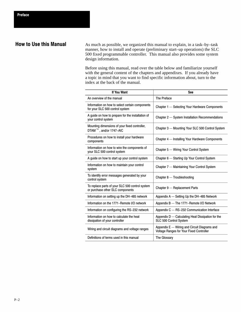
As much as possible, we organized this manual to explain, in a task–by–taskmanner, how to install and operate (preliminary start–up operations) the SLC500 fixed programmable controller. This manual also provides some systemdesign information.
Before using this manual, read over the table below and familiarize yourselfwith the general content of the chapters and appendixes. If you already havea topic in mind that you want to find specific information about, turn to theindex at the back of the manual.
If You Want See
An overview of the manual The Preface
Information on how to select certain componentsfor your SLC 500 control system
Chapter 1 Selecting Your Hardware Components
A guide on how to prepare for the installation ofyour control system
Chapter 2 System Installation Recommendations
Mounting dimensions of your fixed controller,
DTAM, and/or 1747-AICChapter 3 Mounting Your SLC 500 Control System
Procedures on how to install your hardwarecomponents
Chapter 4 Installing Your Hardware Components
Information on how to wire the components ofyour SLC 500 control system
Chapter 5 Wiring Your Control System
A guide on how to start up your control system Chapter 6 Starting Up Your Control System
Information on how to maintain your controlsystem
Chapter 7 Maintaining Your Control System
To identify error messages generated by yourcontrol system
Chapter 8 Troubleshooting
To replace parts of your SLC 500 control systemor purchase other SLC components
Chapter 9 Replacement Parts
Information on setting up the DH-485 network Appendix A Setting Up the DH-485 Network
Information on the 1771-Remote I/O network Appendix B The 1771-Remote I/O Network
Information on configuring the RS-232 network Appendix C RS-232 Communication Interface
Information on how to calculate the heatdissipation of your controller
Appendix D Calculating Heat Dissipation for theSLC 500 Control System
Wiring and circuit diagrams and voltage rangesAppendix E Wiring and Circuit Diagrams andVoltage Ranges for Your Fixed Controller
Definitions of terms used in this manual The Glossary
How to Use this Manual

Preface
P–3
The table below provides a listing of publications that contain importantinformation about Allen–Bradley Small Logic Controllers and theirinstallation and application. You may want to reference them while you areinstalling the SLC 500 controller. (To obtain a copy of one of thesepublications, contact your local Allen–Bradley office or distributor.)
For Read this DocumentDocumentNumber
An overview of the SLC 500 family of products SLC 500 System Overview 1747-2.30
A description on how to install and use your Modular SLC 500programmable controller
Installation & Operation Manual for Modular HardwareStyle Programmable Controllers
1747-6.2
A procedural manual for technical personnel who use APS to developcontrol applications
Advanced Programming Software (APS) User Manual 9399-APSUM
A reference manual that contains status file data, instruction set, andtroubleshooting information about APS
SLC 500 and MicroLogix 1000 Instruction SetReference Manual
1747-6.15
An introduction to APS for first-time users, containing basic concepts butfocusing on simple tasks and exercises, and allowing the reader to beginprogramming in the shortest time possible
APS Quick Start for New Users 9399-APSQS
A procedural and reference manual for technical personnel who use theAPS import/export utility to convert APS files to ASCII and converselyASCII to APS files
APS Import/Export User Manual 9399-APSIE
A procedural and reference manual for technical personnel who use anHHT to develop control applications
Allen-Bradley Hand-Held Terminal User Manual 1747-NP002
An introduction to HHT for first-time users, containing basic concepts butfocusing on simple tasks and exercises, and allowing the reader to beginprogramming in the shortest time possible
Getting Started Guide for HHT 1747-NM009
In-depth information on grounding and wiring Allen-Bradleyprogrammable controllers
Allen-Bradley Programmable Controller Grounding andWiring Guidelines
1770-4.1
A description on how to install a PLC-5 systemPLC-5 Family Programmable Controllers HardwareInstallation Manual
1785-6.6.1
A description of important differences between solid-state programmablecontroller products and hard-wired electromechanical devices
Application Considerations for Solid-State Controls SGI-1.1
An article on wire sizes and types for grounding electrical equipment National Electrical Code
Published by theNational FireProtectionAssociation ofBoston, MA.
A complete listing of current Automation Group documentation, includingordering instructions. Also indicates whether the documents areavailable on CD-ROM or in multi-languages.
Allen-Bradley Publication Index SD499
A glossary of industrial automation terms and abbreviations Allen-Bradley Industrial Automation Glossary AG-7.1
Related PublicationsRelated Publications

Preface
P–4
The following conventions are used throughout this manual:
• Bulleted lists such as this one provide information, not procedural steps.• Numbered lists provide sequential steps or hierarchical information.• Italic type is used for emphasis.• Dimensions are in millimeters. (Dimensions in parentheses are in
inches.)• Text in this font indicates words or phrases you should type.
Allen–Bradley offers support services worldwide, with over 75 Sales/Supportoffices, 512 authorized Distributors and 260 authorized Systems Integratorslocated throughout the United States alone, plus Allen–Bradleyrepresentatives in every major country in the world.
Local Product Support
Contact your local Allen–Bradley representative for:
• sales and order support• product technical training• warranty support• support service agreements
Technical Product Assistance
If you need to contact Allen–Bradley for technical assistance, please reviewthe information in the Troubleshooting chapter first. Then call your localAllen–Bradley representative.
Your Questions or Comments on this Manual
If you find a problem with this manual, please notify us of it on the enclosedPublication Problem Report.
If you have any suggestions for how this manual could be made more usefulto you, please contact us at the address below:
Allen–Bradley Company, Inc.
Automation Group
Technical Communication, Dept. 602V, T122
P.O. Box 2086
Milwaukee, WI 53201–2086
Conventions Used in thisManual
Allen-Bradley Support
1Chapter
1–1
Selecting Your Hardware Components
This chapter provides general information on what your SLC 500 controllercan do for you and an overview of the fixed control system. It also explainshow to select:
• 2–slot chassis• discrete I/O modules• specialty I/O modules• enclosures• operator interfaces• memory modules• isolation transformers• suppressors• output contact protection
There is also a section on special considerations for controller installations.
This chapter does not provide you with all the information that you need toselect a complete SLC 500 control system. To do this, we recommend thatyou use the latest version of the system overview, SLC 500 Family of SmallProgrammable Controllers, Publication Number 1747–2.30.
The SLC 500 programmable controller has features that previously couldonly be found in large programmable controllers. It has the flexibility andpower of a large controller with the size and simplicity of a small controller.The SLC 500 controller offers you more control options than any otherprogrammable controller in its class.
These programmable controllers make up a technologically advanced controlsystem having inherent flexibility and advantages characteristic of otherprogrammable controllers, but with one important difference — simplicity!
What Your SLC 500 ControllerCan Do for You

Chapter 1
Selecting Your Hardware Components
1–2
The basic fixed controller consists of a processor with 1,024 (1K) instructioncapacity, a power supply, and a fixed number of I/O contained in a singlepackage. The figure below shows typical hardware components for a fixedcontroller.
Input Module Output Module
Operator Interface
Fixed Controller with 2-slot Expansion ChassisFixed Hardware Components
2-Slot Expansion Chassisfor I/O Modules
Fixed Hardware Controller
Overview of Your FixedControl System
Chapter 1
Selecting Your Hardware Components
1–3
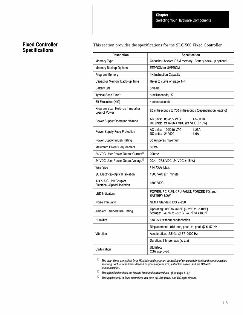
This section provides the specifications for the SLC 500 Fixed Controller.
Description Specification
Memory Type Capacitor-backed RAM memory. Battery back-up optional.
Memory Backup Options EEPROM or UVPROM
Program Memory 1K Instruction Capacity
Capacitor Memory Back-up Time Refer to curve on page 1-4.
Battery Life 5 years
Typical Scan Time➀ 8 milliseconds/1K
Bit Execution (XIC) 4 microseconds
Program Scan Hold-up Time afterLoss of Power
20 milliseconds to 700 milliseconds (dependent on loading)
Power Supply Operating VoltageAC units: 85-265 VAC 47-63 HzDC units: 21.6-26.4 VDC (24 VDC ± 10%)
Power Supply Fuse ProtectionAC units: 120/240 VAC 1.25ADC units: 24 VDC 1.6A
Power Supply Inrush Rating 30 Amperes maximum
Maximum Power Requirement 50 VA➁
24 VDC User Power Output Current➂ 200mA
24 VDC User Power Output Voltage➂ 20.4 - 27.6 VDC (24 VDC ± 15 %)
Wire Size #14 AWG Max.
I/O Electrical-Optical Isolation 1500 VAC at 1 minute
1747-AIC Link CouplerElectrical-Optical Isolation
1500 VDC
LED IndicatorsPOWER, PC RUN, CPU FAULT, FORCED I/O, andBATTERY LOW
Noise Immunity NEMA Standard ICS 2-230
Ambient Temperature RatingOperating: 0°C to +60°C (+32°F to +140°F)Storage: 40°C to +85°C (-40°F to +185°F)
Humidity 5 to 95% without condensation
Displacement: .015 inch, peak-to-peak @ 5-57 Hz
Vibration Acceleration: 2.5 Gs @ 57-2000 Hz
Duration: 1 hr per axis (x, y, z)
CertificationUL listed/CSA approved
➀ The scan times are typical for a 1K ladder logic program consisting of simple ladder logic and communicationservicing. Actual scan times depend on your program size, instructions used, and the DH-485communication.
➁ This specification does not include input and output values. (See page 1-6.)➂ This applies only to fixed controllers that have AC line power and DC input circuits.
Fixed ControllerSpecifications
Chapter 1
Selecting Your Hardware Components
1–4
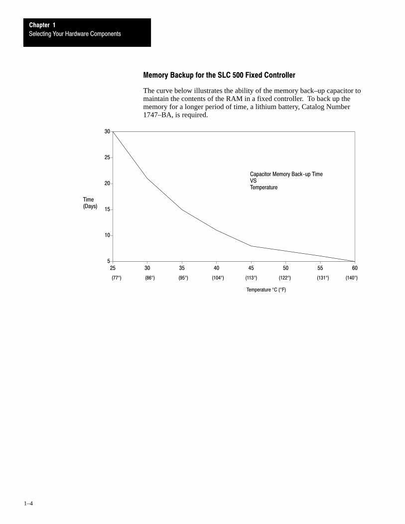
Memory Backup for the SLC 500 Fixed Controller
The curve below illustrates the ability of the memory back–up capacitor tomaintain the contents of the RAM in a fixed controller. To back up thememory for a longer period of time, a lithium battery, Catalog Number1747–BA, is required.
5
10
15
20
25
30
25 30 35 40 45 50 55 60
Temperature °C (°F)
(77°) (86°) (95°) (104°) (113°) (122°) (131°) (140°)
Capacitor Memory Back-up TimeVSTemperature
Time (Days)

Chapter 1
Selecting Your Hardware Components
1–5
Configuration Options
The following table provides configuration options for 20, 30, or 40 I/Opoints.
CatalogLine Power
I/O Configuration High-SpeedUser Power
CatalogNumber
Line PowerInput Output
High-SpeedCounter
User Power
1747-L20A (12) 120 Volts AC (8) AC/DC Relay No NA
1747-L30A (18) 120 Volts AC (12) AC/DC Relay No NA
1747-L40A (24) 120 Volts AC (16) AC/DC Relay No NA
1747-L20B (12) 120 Volts AC (8) AC Triac No NA
1747-L30B (18) 120 Volts AC (12) AC Triac No NA
1747-L40B (24) 120 Volts AC (16) AC Triac No NA
1747-L20C (12) 24 Volts DC Sink (8) AC/DC Relay Yes 24V-200mA
1747-L30C (18) 24 Volts DC Sink (12) AC/DC Relay Yes 24V-200mA
1747-L40C (24) 24 Volts DC Sink (16) AC/DC Relay Yes 24V-200mA
1747-L20D (12) 24 Volts DC Sink (8) AC Triac Yes 24V-200mA
1747-L30D (18) 24 Volts DC Sink (12) AC Triac Yes 24V-200mA
1747-L20E120/240 VAC
(12) 24 Volts DC Sink(8) DC TransistorSource
Yes 24V-200mA
1747-L40E (24) 24 Volts DC Sink(16) DC TransistorSource
Yes 24V-200mA
1747-L20L(12) 24 Volts DCSource
(8) DC TransistorSink
Yes 24V-200mA
1747-L30L(18) 24 Volts DCSource
(12) DC TransistorSink
Yes 24V-200mA
1747-L40L(24) 24 Volts DCSource
(16) DC TransistorSink
Yes 24V-200mA
1747-L20R (12) 240 Volts AC (8) AC/DC Relay No NA
1747-L20P (12) 240 Volts AC (8) AC Triac No NA
1747-L30P (18) 240 Volts AC (12) AC Triac No NA
1747-L40P (24) 240 Volts AC (16) AC Triac No NA
1747-L20F (12) 24 Volts DC Sink (8) AC/DC Relay Yes NA
1747-L40F (24) 24 Volts DC Sink (16) AC/DC Relay Yes NA
1747-L20G24 VDC±10% (12) 24 Volts DC Sink
(8) DC TransistorSource
Yes NA
1747-L20N(12) 24 Volts DCSource
(8) DC TransistorSink
Yes NA
Chapter 1
Selecting Your Hardware Components
1–6
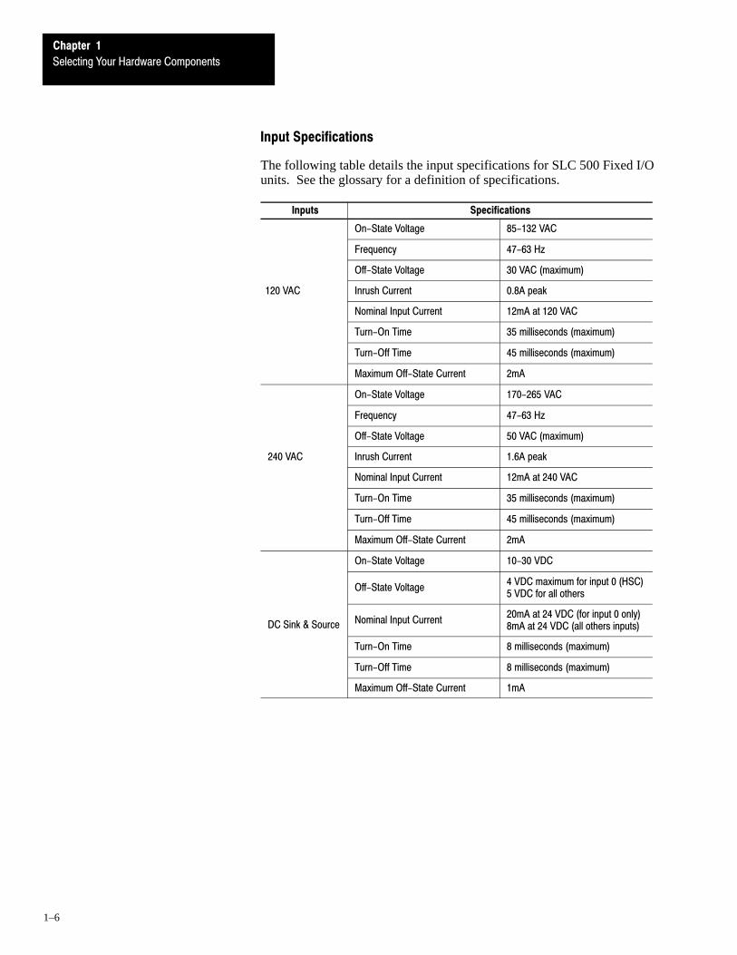
Input Specifications
The following table details the input specifications for SLC 500 Fixed I/Ounits. See the glossary for a definition of specifications.
Inputs Specifications
On-State Voltage 85-132 VAC
Frequency 47-63 Hz
Off-State Voltage 30 VAC (maximum)
120 VAC Inrush Current 0.8A peak
Nominal Input Current 12mA at 120 VAC
Turn-On Time 35 milliseconds (maximum)
Turn-Off Time 45 milliseconds (maximum)
Maximum Off-State Current 2mA
On-State Voltage 170-265 VAC
Frequency 47-63 Hz
Off-State Voltage 50 VAC (maximum)
240 VAC Inrush Current 1.6A peak
Nominal Input Current 12mA at 240 VAC
Turn-On Time 35 milliseconds (maximum)
Turn-Off Time 45 milliseconds (maximum)
Maximum Off-State Current 2mA
On-State Voltage 10-30 VDC
Off-State Voltage4 VDC maximum for input 0 (HSC)5 VDC for all others
DC Sink & Source Nominal Input Current20mA at 24 VDC (for input 0 only)8mA at 24 VDC (all others inputs)
Turn-On Time 8 milliseconds (maximum)
Turn-Off Time 8 milliseconds (maximum)
Maximum Off-State Current 1mA
Chapter 1
Selecting Your Hardware Components
1–7
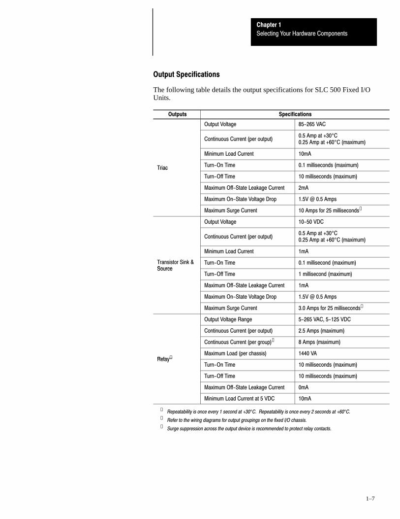
Output Specifications
The following table details the output specifications for SLC 500 Fixed I/OUnits.
Outputs Specifications
Output Voltage 85-265 VAC
Continuous Current (per output)0.5 Amp at +30°C0.25 Amp at +60°C (maximum)
Minimum Load Current 10mA
Triac Turn-On Time 0.1 milliseconds (maximum)Triac
Turn-Off Time 10 milliseconds (maximum)
Maximum Off-State Leakage Current 2mA
Maximum On-State Voltage Drop 1.5V @ 0.5 Amps
Maximum Surge Current 10 Amps for 25 milliseconds➀
Output Voltage 10-50 VDC
Continuous Current (per output)0.5 Amp at +30°C0.25 Amp at +60°C (maximum)
Minimum Load Current 1mA
Transistor Sink &Source
Turn-On Time 0.1 millisecond (maximum)Source
Turn-Off Time 1 millisecond (maximum)
Maximum Off-State Leakage Current 1mA
Maximum On-State Voltage Drop 1.5V @ 0.5 Amps
Maximum Surge Current 3.0 Amps for 25 milliseconds➀
Output Voltage Range 5-265 VAC, 5-125 VDC
Continuous Current (per output) 2.5 Amps (maximum)
Continuous Current (per group)➁ 8 Amps (maximum)
Relay➂Maximum Load (per chassis) 1440 VA
Relay➂
Turn-On Time 10 milliseconds (maximum)
Turn-Off Time 10 milliseconds (maximum)
Maximum Off-State Leakage Current 0mA
Minimum Load Current at 5 VDC 10mA
➀ Repeatability is once every 1 second at +30°C. Repeatability is once every 2 seconds at +60°C.➁ Refer to the wiring diagrams for output groupings on the fixed I/O chassis.➂ Surge suppression across the output device is recommended to protect relay contacts.

Chapter 1
Selecting Your Hardware Components
1–8
Relay Contact Ratings
MaximumVolts
AmperesMake Break
AmperesContinuous
VoltamperesMake Break
240 VAC120 VAC
7.5A15A
0.75A1.5A 2.5A 1800 VA 180 VA
125 VDC 0.22A 1.0A 28 VA
24 VDC 1.2A 2.0A 28 VA
To calculate make and break ratings for other load voltages, divide thevoltampere rating by the load voltage; for example:
28 VA/48 VDC = 0.583 A
For the 20, 30, and 40 I/O fixed controllers, an optional 2–slot expansionchassis lets you add two additional I/O modules providing even moreversatility. The power supply provides backplane power for the modules inthe optional expansion chassis.
Refer to chapter 3 for chassis dimensions and chapter 4 for mountingdirections.
There are three types of I/O modules: input, output, and combination I/O.They are available in a wide variety of densities including 4, 8, 16, and 32point and can interface to AC, DC, and TTL voltage levels. Output modulesare available with solid–state AC, solid–state DC, and relay contact typeoutputs.
For a complete, up–to–date listing of discrete I/O modules and theirspecifications, contact your Allen–Bradley sales office for the latest productdata entitled Discrete Input and Output Modules, Publication Number1746–2.35.
Refer to chapter 4 for installation directions.
The SLC 500 family offers specialty I/O modules that enhance your controlsystem. These modules range in function from analog interface to motioncontrol, from communication to high–speed counting.
For a complete, up–to–date listing of specialty I/O modules and theirspecifications, contact your Allen–Bradley sales office for the latest SystemOverview entitled SLC 500 Family of Small Programmable Controllers,Publication Number 1747–2.30, or for a related product data.
Refer to chapter 4 for installation directions.
Selecting the 2-Slot Chassis
Selecting Discrete I/OModules
Selecting Speciality I/OModules

Chapter 1
Selecting Your Hardware Components
1–9
The enclosure protects the equipment from atmospheric contamination.Standards established by the National Electrical Manufacturer’s Association(NEMA) define enclosure types, based on the degree of protection anenclosure will provide. Use a fan to circulate the air of sealed enclosures thatuse convection cooling to dissipate heat. Select a NEMA–rated enclosurethat suits your application and environment. The enclosure should beequipped with a disconnect device. To calculate the heat dissipation of yourcontroller, see appendix D.
Use an operator interface to program and/or monitor your SLC 500controller. You can choose from several Allen–Bradley operator interfacedevices.
Programming with a Hand-Held Terminal (1747-PT1)
Use the Hand–Held Terminal (HHT) to configure the SLC 500 controller,enter/modify a user program, download/upload programs, monitor controloperation, and test/troubleshoot. When equipped with a battery (1747–BA),the HHT retains a user program in memory for storage and later use.
The display area accommodates 8 lines x 40 characters. You can display fiverungs of a user program. The top row of keys are the menu function keys.
Important: Using the HHT, you can program the SLC 5/01 and 5/02processors and the SLC 500 fixed controllers. You cannot,however, program the SLC 5/03 processor.
Refer to the Hand–Held Terminal User Manual, Catalog Number1747–NP002, for information on programming your fixed controller with theHHT.
Programming with Advanced Programming Software (APS) on an IBMCompatible Computer
The Advanced Programming Software (APS) can be used with anAllen-Bradley T45, T47, or T50 terminal, an IBM-AT or XT, a CompaqPortable, Portable II, Deskpro 286, 386/SX, 386, a Tandy 3000HL,Toshiba 3100E, or GATEWAY 2000 models 386DX/25, 386DX/33,486DX/33, and 486DX2/50 personal computer. Your computer must have:
• 640 Kbytes of RAM (extended or expanded memory is recommended, butnot required)
• 10 Mbyte fixed-disk drive (APS requires a minimum or 2.5 MBytes offree disk space.)
• DOS version 3.1 or higher
Selecting Enclosures
Selecting Operator Interfaces

Chapter 1
Selecting Your Hardware Components
1–10
Advanced Programming Software, 1747–PA2E
APS, Catalog Number 1747–PA2E, comes on 5–1/4 and 3–1/2 inch disks.You must have DOS installed in your computer. You also must have at least550 Kbytes of free memory to execute the APS software. Like theHand–Held Terminal, APS lets you configure the SLC 500 controller,enter/modify a user program, restore/save programs to the SLC 500, monitorcontroller operation, and test/troubleshoot. You can also:
• create and print ladder diagrams, data tables, instruction cross references,and configurations
• use cut/copy/paste editor• store multiple programs in the memory of the computer (on the hard disk)Refer to the Advanced Programming Software User Manual, CatalogNumber 1747–NM002, and the Advanced Programming Software ReferenceManual, Catalog Number 1747–NR001, for information on programmingyour fixed controller with APS.
DH–485 Interface Converter (1747–PIC)
For communication, use an RS–232/DH–485 Interface Converter betweenthe computer and SLC controller. The converter includes a 279.4 mm (11.0in.) ribbon cable, already attached to the converter, for connection to thecomputer serial port and a Catalog Number 1746–C10 cable for connectionto the controller.
Monitoring with a Data Table Access Module (1747-DTAM-E)
The Data Table Access Module (DTAM) is a plant floor device that lets youaccess data file information, change operating modes, monitor and clearprocessor faults, and transfer the user program between RAM and anEEPROM memory module with any SLC 500 family processor. You cannotuse it to create new programs.
Important features of DTAM include:
• shorthand addressing, which provides easier access to data files• display prompts in six, user–selectable languages: English, French,
German, Italian, Spanish, and Japanese• UL listed, CSA Certified• NEMA type 12 and 13 enclosures• point–to–point interface to an SLC family processor, or as a network
device on a DH–485 networkRefer to the Data Table Access Module (DTAM) User Manual, CatalogNumber 1747–ND013, for information on monitoring your fixed controllerwith the DTAM.
Chapter 1
Selecting Your Hardware Components
1–11
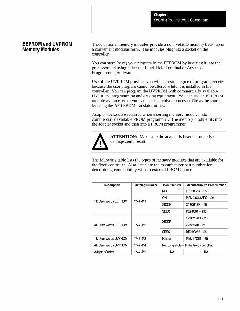
These optional memory modules provide a non–volatile memory back–up ina convenient modular form. The modules plug into a socket on thecontroller.
You can store (save) your program in the EEPROM by inserting it into theprocessor and using either the Hand–Held Terminal or AdvancedProgramming Software.
Use of the UVPROM provides you with an extra degree of program securitybecause the user program cannot be altered while it is installed in thecontroller. You can program the UVPROM with commercially availableUVPROM programming and erasing equipment. You can use an EEPROMmodule as a master, or you can use an archived processor file as the sourceby using the APS PROM translator utility.
Adapter sockets are required when inserting memory modules intocommercially available PROM programmer. The memory module fits intothe adapter socket and then into a PROM programmer.
!ATTENTION: Make sure the adapter is inserted properly ordamage could result.
The following table lists the types of memory modules that are available forthe fixed controller. Also listed are the manufacturer part number fordetermining compatibility with an external PROM burner.
Description Catalog Number Manufacturer Manufacturer's Part Number
NEC uPD28C64 - 250
1K User Words EEPROM 1747-M1OKI MSM28C64ARS - 20
1K User Words EEPROM 1747-M1XICOR X28C64BP - 25
SEEQ PE28C64 - 250
XICORX28C256DI - 25
4K User Words EEPROM 1747-M2XICOR
X28256DI - 25
SEEQ DE28C256 - 25
1K User Words UVPROM 1747-M3 Fujitsu MBM27C64 - 25
4K User Words UVPROM 1747-M4 Not compatible with the fixed controller.
Adaptor Socket 1747-M5 NA NA
EEPROM and UVPROMMemory Modules

Chapter 1
Selecting Your Hardware Components
1–12
If there is high frequency conducted noise in or around your distributionequipment, we recommend that you use an isolation transformer in the ACline to the power supply. This type of transformer provides isolation fromyour power distribution system and is often used as a “step down”transformer to reduce line voltage. Any transformer used with the controllermust have a sufficient power rating for its load. This power rating isgenerally expressed in voltamperes (VA).
To select an appropriate isolation transformer, you must calculate the powerrequired by the fixed I//O chassis and any input circuits and output loads thatare connected through this transformer. The power requirement of any fixedI/O unit is 50 VA.
The power requirement for the input circuits is determined by the number ofinputs, the operating voltage, and the nominal input current. The powerrequirement for output loads is determined by the number of outputs, theload voltage, and load current.
For example, if you have a 1747–L30B fixed unit with 18 AC inputs (12mAat 120 VAC) and 12 triac outputs (0.5A at 120 VAC), the power consumedwould be:
50 + (18)(120)(0.012) + (12)(120)(0.5) = 796 VA
Important: In this case, 0.5 Amp is the maximum rating of the triac output(at +30° C). If your load draws less than 0.5 Amp, this figuremay be reduced accordingly. The output portion of the VAcalculation should reflect the current requirements of yourloads.
In general, we recommend that the transformer is oversized to provide somemargin for line voltage variations and other factors. Typically a transformerthat is 25% larger than the calculated VA is sufficient.
Selecting IsolationTransformers

Chapter 1
Selecting Your Hardware Components
1–13
The recommendations given previously provide favorable operatingconditions for most controller installations. Your application may involveone or more of the following adverse conditions. Additional measures canbe taken to minimize the effect of these conditions.
Excessive Line Voltage Variations
The best solution for excessive line voltage variation is to correct any feederproblems in your distribution system. Where this does not solve the linevariation problem, or in certain critical applications, use a constant voltagetransformer. If you require a constant voltage transformer, connect it to thepower supply and all input devices connected to the SLC 500 controller.
Connect output devices on the same power line, but their connection alongthe power line is normally made before the constant voltage transformer. Aconstant voltage transformer must have a sufficient power rating for its load.
Excessive Noise
When you operate the SLC 500 controller in a “noise polluted” industrialenvironment, special consideration should be given to possible electricalinterference.
The following reduces the effect of electrical interference:
• SLC 500 controller design features• proper mounting of controller within an enclosure• proper equipment grounding• proper routing of wiring• proper suppression added to noise generating devices
Potential noise generators include inductive loads, such as relays, solenoids,and motor starters when operated by “hard contacts” like push buttons orselector switches. Suppression may be necessary when such loads areconnected as output devices or when connected to the same supply line thatpowers the controller.
Lack of surge suppression on inductive loads may attribute to processorfaults and sporadic operation, RAM memory can be corrupted (lost) and I/Omodules may appear to be faulty or reset themselves.
For extremely noisy environments, use a memory module and program it forauto loading on processor fault or power cycle for quick recovery.
Special Considerations

Chapter 1
Selecting Your Hardware Components
1–14
Selecting Surge Suppressors
Most output modules have built–in surge suppression to reduce the effects ofhigh voltage transients. However, we recommend that you use an additionalsuppression device if an output module is being used to control an inductivedevice such as:
• relays • motor starters• solenoids • motors
Additional suppression is especially important if your inductive device is inseries with or parallel to a hard contact such as:
• pushbuttons • selector switches
By adding a suppression device directly across the coil of an inductivedevice, you will reduce the effects of voltage transients caused byinterrupting the current to that inductive device and prolong the life of theswitch contacts. The diagram below shows an output module with asuppression device.
OUT 5
OUT 6
OUT 7
OUT 2
VAC/VDC
OUT 0
OUT 1
OUT 3
COM
+ DC or L1
OUT 4
Snubber
AC or DCOutput Module
DC COM or L2
If you connect an SLC 500 controller triac output to control an inductiveload, we recommend that you use varistors to suppress noise. Choose avaristor that is appropriate for the application. The surge suppression werecommend for triac outputs when switching 120 VAC inductive loads isHarris MOV, part number V220 MA2A. For a 509 motor starter, use a599–K04 or 599–KA04 series C or later MOV with triac outputs.
Consult the varistor manufacturer’s data sheet when selecting a varistor foryour application.
!ATTENTION: Damage could occur to SLC 500 triac outputs ifyou use suppressors having RC networks. Allen–Bradley ACsurge suppressors not recommended for use with triacs includeCatalog Numbers 199–FSMA1, 199–FSMA2, 1401–N10, and700–N24.

Chapter 1
Selecting Your Hardware Components
1–15
Allen–Bradley surge suppressors recommended for use with Allen–Bradleyrelays, contactors, and starters are shown in the table below.
Device Coil VoltageSuppressor Catalog
Number
Bulletin 509 Motor StarterBulletin 509 Motor Starter
120 VAC240 VAC
599-K04➀
599-KA04➀
Bulletin 100 ContactorBulletin 100 Contactor
120 VAC240 VAC
199-FSMA1➁
199-F5MA2➁
Bulletin 709 Motor Starter 120 VAC 1401-N10➁
Bulletin 700 Type R, RM Relays AC coil None Required
Bulletin 700 Type R RelayBulletin 700 Type RM Relay
12 VDC12 VDC
700-N22700-N28
Bulletin 700 Type R RelayBulletin 700 Type RM Relay
24 VDC24 VDC
700-N10700-N13
Bulletin 700 Type R RelayBulletin 700 Type RM Relay
48 VDC48 VDC
700-N16700-N17
Bulletin 700 Type R RelayBulletin 700 Type RM Relay
115-125 VDC115-125 VDC
700-N11700-N14
Bulletin 700 Type R RelayBulletin 700 Type RM Relay
230-250 VDC230-250 VDC
700-N12700-N15
Bulletin 700 Type N, P, or PK Relay
Miscellaneouselectromagnetic devices limited to 35sealed VA
150V max, AC or DC 700-N24➁
➀ This is an MOV without a capacitor. The 599-K04 or 599-KA04 MOV must be series C or later when usedwith triac outputs. Do not use series A or B with triac outputs.
➁ Not recommended for use with triac outputs.
Chapter 1
Selecting Your Hardware Components
1–16
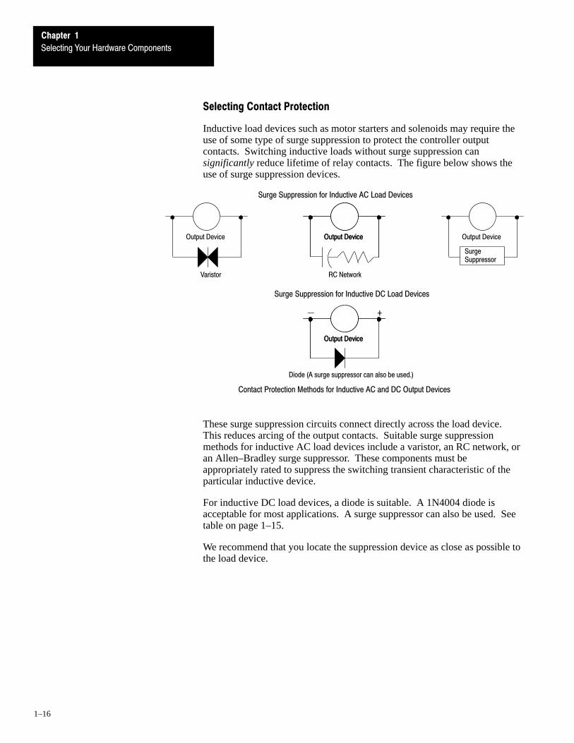
Selecting Contact Protection
Inductive load devices such as motor starters and solenoids may require theuse of some type of surge suppression to protect the controller outputcontacts. Switching inductive loads without surge suppression cansignificantly reduce lifetime of relay contacts. The figure below shows theuse of surge suppression devices.
Output Device
Varistor
Output DeviceOutput Device Output Device
RC Network
SurgeSuppressor
Output DeviceOutput Device
Diode (A surge suppressor can also be used.)
+
Surge Suppression for Inductive DC Load Devices
Surge Suppression for Inductive AC Load Devices
Contact Protection Methods for Inductive AC and DC Output Devices
These surge suppression circuits connect directly across the load device.This reduces arcing of the output contacts. Suitable surge suppressionmethods for inductive AC load devices include a varistor, an RC network, oran Allen–Bradley surge suppressor. These components must beappropriately rated to suppress the switching transient characteristic of theparticular inductive device.
For inductive DC load devices, a diode is suitable. A 1N4004 diode isacceptable for most applications. A surge suppressor can also be used. Seetable on page 1–15.
We recommend that you locate the suppression device as close as possible tothe load device.
Chapter 1
Selecting Your Hardware Components
1–17
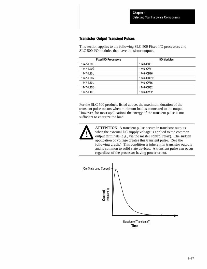
Transistor Output Transient Pulses
This section applies to the following SLC 500 Fixed I/O processors andSLC 500 I/O modules that have transistor outputs.
Fixed I/O Processors I/O Modules
1747-L20E 1746-OB8
1747-L20G 1746-OV8
1747-L20L 1746-OB16
1747-L20N 1746-OBP16
1747-L30L 1746-OV16
1747-L40E 1746-OB32
1747-L40L 1746-OV32
For the SLC 500 products listed above, the maximum duration of thetransient pulse occurs when minimum load is connected to the output.However, for most applications the energy of the transient pulse is notsufficient to energize the load.
ATTENTION: A transient pulse occurs in transistor outputswhen the external DC supply voltage is applied to the commonoutput terminals (e.g., via the master control relay). The suddenapplication of voltage creates this transient pulse. (See thefollowing graph.) This condition is inherent in transistor outputsand is common to solid state devices. A transient pulse can occurregardless of the processor having power or not.
!
Duration of Transient (T)
Tran
sien
t (I)
(On-State Load Current)
Cu
rren
t
Time

Chapter 1
Selecting Your Hardware Components
1–18
To reduce the possibility of inadvertent operation of devices connected totransistor outputs, adhere to the following guidelines:
• Either ensure that any programmable device connected to the transistoroutput is programmed to ignore all output signals until after the transientpulse has ended,
• or add an external resistor in parallel to the load to increase the on–stateload current. The duration of the transient pulse is reduced when theon–state load current is increased.
The duration of the transient pulse is proportional to the load impedance.This is illustrated in the following graph.
0
On-State Load Current (mA)
1000
1
2
3
4
5
6
7
8
9
10
1 100 200 300 400 500 600 700 800 900
Dur
atio
n of
Tra
nsie
nt (
ms)
Tim
e

Chapter 1
Selecting Your Hardware Components
1–19
Example
Increasing the load current by 100mA decreases the transient time fromapproximately 7 ms to less than 2.5 ms. To calculate the size of the resistoradded in parallel to increase the current, use the following information:
R (Ohms)V (Volts)
I (Amps)
Resistor value (Ohms) = Applied voltage (Volts) / Desired current (Amps)= 24 / 0.1
P (Watts) = I2 (Amps) x R (Ohms)
Actual Power (Watts) = (Desired Current)2 x Resistor Value
Resistor size = 2 x Actual power (Watts)= 2 x 2.4
Round resistor size to 5 Watts.
= 2.4 (Watts)
=
24V = your applied voltage
Need 100mA of load current to reduce the transient to < 2.5 ms. (taken from graph onprevious page)
= 240 (Ohms)
= (0.1)2 x 240
= 4.8 (Watts)
You need a resistor rated for 240 Ohms at 5 Watts to increase the load currentby 100mA; thus decreasing the transient time from approximately 7 ms toless than 2.5 ms.


2Chapter
2–1
System Installation Recommendations
To help you install the SLC 500 programmable controller as safely andsecurely as possible, we have set up a few specific recommendations for youto follow.
For general installation guidelines, also refer to article 70E of the NationalFire Protection Association (NFPA). Article 70E describes electrical safetyrequirements for employee workplaces. This chapter covers the following:
• typical installation• spacing your controllers• preventing excessive heat• grounding guidelines• master control relay• power considerations• safety considerations• preventative maintenance
The figure below consists of some components that make up a typicalinstallation. The following symbols are used:
1
NEMA rated enclosure suitable for your application and
environment that shields your controller from electrical noise
and airborne contaminants.
1
Disconnect, to remove power from the system2
Fused isolation transformer or a constant voltage transformer, as
your application requires
3
DisconnectDevice
IsolationTransformer
SLC 500Controller
MCR
Master control relay/emergency stop circuit4Terminal blocks or wiring ducts5
Suppression devices for limiting EMI (electromagnetic
interference) generation
6
4
6
5
3
2
Typical Installation

Chapter 2
System Installation Recommendations
2–2
Follow the recommended minimum spacing shown below to allow forconvection cooling within the enclosure. Air in the enclosure must be keptwithin a range of 0° to +60° C (+32° to +140° F).
Important: Be careful of metal chips when drilling mounting holes for thecontrollers. Do not drill holes above a mounted SLC 500controller. Metal chips or clippings may short circuit electroniccomponents of the controller and cause intermittent orpermanent malfunction.
Greater than 101.6 mm(4 inches)
Enclosure
Greater than 152.4 mm (6 inches)
Greater than 152.4 mm (6 inches)
Greater than 101.6 mm(4 inches)
For most applications, normal convection cooling will keep the controllercomponents within the specified operating range. Proper spacing ofcomponents within the enclosure is usually sufficient for heat dissipation.
In some applications, a substantial amount of heat is produced by otherequipment inside or outside the enclosure. In this case, place blower fansinside the enclosure to assist in air circulation and to reduce “hot spots” nearthe controller.
Additional cooling provisions might be necessary when high ambienttemperatures are encountered.
Important: Do not bring in unfiltered outside air. It may introduce harmfulcontaminants of dirt that could cause improper operation ordamage to components. In extreme cases, you may need to useair conditioning to protect against heat build–up within theenclosure.
Spacing Your Components
Preventing Excessive Heat

Chapter 2
System Installation Recommendations
2–3
In solid–state control systems, grounding helps limit the effects of noise dueto electromagnetic interference (EMI). The grounding path for the controllerand its enclosure is provided by the equipment grounding conductor.
Chassis Mounting Tab
#10 AWG to Ground Bus
Chassis Mounting TabGroundLug
Size 12 InternalStar Washer
Tapped Hole(Minimum of ThreeThreads)
Metal Panel(Must be connected to earthground.)
Scrape paint off panel to insureelectrical connection between chassisand grounded metal panel.
Tapped Hole(Minimum of ThreeThreads)
Size 12 InternalStar Washer
Scrape paint off panel to insureelectrical connection between chassis and grounded metal panel.
Normal Electrical Noise Conditions Severe Electrical Noise Conditions
Metal Panel(Must be connected toearth ground.)
Size 10 or 12Hardware Screw
Size 10 or 12Hardware Screw
Size 12 InternalStar Washer
!ATTENTION: The SLC 500 controller, other control devices,and the enclosure must be properly grounded. All applicablecodes and ordinances must be observed when wiring thecontroller system.
Ground connections should run from the chassis and power supply on eachcontroller and expansion unit to the ground bus. Exact connections willdiffer between applications. An authoritative source on groundingrequirements for most installations is the National Electrical Code. Also,refer to Allen–Bradley Programmable Controller Grounding and WiringGuidelines, Publication Number 1770–4.1.
In addition to the grounding required for the controller and its enclosure, youmust also provide proper grounding for all controlled devices in yourapplication. Care must be taken to provide each device with an acceptablegrounding path.
Grounding Guidelines

Chapter 2
System Installation Recommendations
2–4
The figure below shows you how to run ground connections from the chassisto the ground bus.
SLC 500 Controller Only
#8 AWGWire
EarthGround
Ground Bus#10 AWG Wire
SLC 500 Controller with 2-slot Expansion Chassis
#8 AWGWire
EarthGround
Ground Bus#10 AWG Wire
Chassis Mounting Tabs
Chassis Mounting Tabs
Chapter 2
System Installation Recommendations
2–5
A hard–wired master control relay (MCR) provides a convenient means foremergency controller shutdown. Since the master control relay allows theplacement of several emergency–stop switches in different locations, itsinstallation is important from a safety standpoint. Overtravel limit switchesor mushroom head push buttons are wired in series so that when any of themopens, the master control relay is de–energized. This removes power to inputand output device circuits. Refer to the figure on page 2–6.
!ATTENTION: Never alter these circuits to defeat their function,since serious injury and/or machine damage could result.
Important: If you are using a DC output power supply, interrupt the outputside rather than the AC line to avoid the additional delay ofpower supply turn–on and turn–off. The power supply shouldreceive its power directly from the fused secondary of thetransformer. Connect the power to the DC input and outputcircuits through a set of master control relay contacts.
Place the main power disconnect switch where operators and maintenancepersonnel have quick and easy access to it. If you mount a disconnect switchinside the controller enclosure, place the switch operating handle on theoutside of the enclosure, so that you can disconnect power without openingthe enclosure.
Whenever any of the emergency–stop switches are opened, power to inputand output devices is stopped.
When you use the master control relay to remove power from the externalI/O circuits, power continues to be provided to the controller’s power supplyso that diagnostic indicators on the processor can still be observed.
The master control relay is not a substitute for a disconnect to the controller.It is intended for any situation where the operator must quickly de–energizeI/O devices only. When inspecting or installing terminal connections,replacing output fuses, or working on equipment within the enclosure, usethe disconnect to shut off power to the rest of the system.
Important: The operator must not control the master control relay with theSLC 500 controller. Provide the operator with the safety of adirect connection between an emergency–stop switch and themaster control relay.
Master Control Relay

Chapter 2
System Installation Recommendations
2–6
Emergency-Stop Switches
Adhere to the following points concerning emergency–stop switches:
• Do not program emergency–stop switches in the controller program. Anyemergency–stop switch should turn off all machine power by turning offthe master control relay.
• Observe all applicable local codes concerning the placement and labelingof emergency–stop switches.
• Install emergency–stop switches and the master control relay in yoursystem. Make certain that relay contacts have a sufficient rating for yourapplication. Emergency–stop switches must be easy to reach.
The figure below shows the Master Control Relay Wired in GroundedSystem.
Disconnect
L1 L2
IsolationTransformer
Fuse
Operation of either of these contacts will removepower from the controller external I/O circuits,stopping machine motion.
MCR
MCR
MCR
Emergency-StopPush Button Overtravel
Limit Switch StopStart
Suppr.
230 VAC
MCR
(Lo) (Hi)
Incoming Line Terminals. Connect to115 VAC terminals of Power Supply.
DC Power Supply.Use N.E.C. Class 2 for UL Listing. MCR
+
115 VACX1 X2
Incoming line terminals. Connect to24 VDC terminals of Power Supply.
24 VDCI/O Circuits
115 VAC I/O Circuits
230 VACI/O Circuits
Master Control Relay (MCR)Cat. No. 700-PK400A1
Fuse
FuseSuppressorCat. No. 700-N24

Chapter 2
System Installation Recommendations
2–7
The following explains power considerations for the SLC 500 fixedcontroller.
Common Power Source
We strongly recommend that the chassis power supply has the same powersource as the input and output devices. This helps:
• reduce the chance of electrical interference due to multiple sources andgrounds
• maintain system integrity if power is interrupted
Loss of Power Source
The chassis power supply is designed to withstand brief power losses withoutaffecting the operation of the system. The time the system is operationalduring power loss is called “program scan hold–up time after loss of power.”The duration of the power supply hold–up time depends on the number, typeand state of the I/O, but is typically between 20 ms and 700 ms. When theduration of power loss reaches a limit, the power supply signals the processorthat it can no longer provide adequate DC power to the system. This isreferred to as a power supply shutdown. The POWER LED is turned off.
Input States on Power Down
The power supply hold–up time as described above is generally longer thanthe turn–on and turn–off times of the input circuits. Because of this, theinput state change from “On” to “Off” that occurs when power is removedmay be recorded by the processor before the power supply shuts down thesystem. Understanding this concept is important. The user program shouldbe written to take this effect into account. For example, hard wire power toone spare input. In the user program, check to be sure that one input is on;otherwise, jump to the end of the program and avoid scanning the logic. Useof a common power source as recommended in the previous section isassumed.
Other Types of Line Conditions
Occasionally the power source to the system can be temporarily interrupted.It is also possible that the voltage level drops substantially below the normalline voltage range for a period of time. Both of these conditions areconsidered to be a loss of power for the system.
Power Considerations
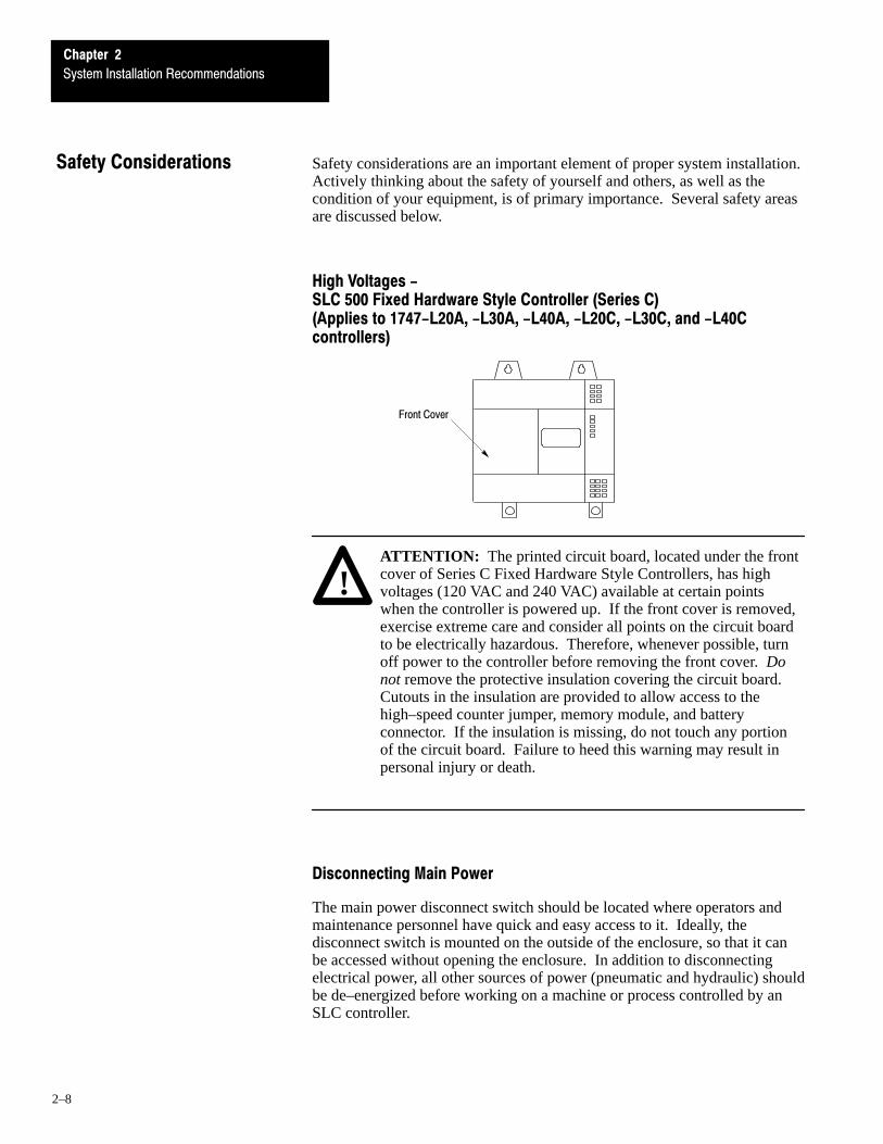
Chapter 2
System Installation Recommendations
2–8
Safety considerations are an important element of proper system installation.Actively thinking about the safety of yourself and others, as well as thecondition of your equipment, is of primary importance. Several safety areasare discussed below.
High Voltages - SLC 500 Fixed Hardware Style Controller (Series C)(Applies to 1747-L20A, -L30A, -L40A, -L20C, -L30C, and -L40Ccontrollers)
Front Cover
!ATTENTION: The printed circuit board, located under the frontcover of Series C Fixed Hardware Style Controllers, has highvoltages (120 VAC and 240 VAC) available at certain pointswhen the controller is powered up. If the front cover is removed,exercise extreme care and consider all points on the circuit boardto be electrically hazardous. Therefore, whenever possible, turnoff power to the controller before removing the front cover. Donot remove the protective insulation covering the circuit board.Cutouts in the insulation are provided to allow access to thehigh–speed counter jumper, memory module, and batteryconnector. If the insulation is missing, do not touch any portionof the circuit board. Failure to heed this warning may result inpersonal injury or death.
Disconnecting Main Power
The main power disconnect switch should be located where operators andmaintenance personnel have quick and easy access to it. Ideally, thedisconnect switch is mounted on the outside of the enclosure, so that it canbe accessed without opening the enclosure. In addition to disconnectingelectrical power, all other sources of power (pneumatic and hydraulic) shouldbe de–energized before working on a machine or process controlled by anSLC controller.
Safety Considerations

Chapter 2
System Installation Recommendations
2–9
Wiring Safety Circuits
Circuits installed on the machine for safety reasons, like overtravel limitswitches, stop push buttons, and interlocks, should always be hard–wireddirectly to the master control relay. These devices must be wired in series sothat when any one device opens, the master control relay is de–energizedthereby removing power to the machine. Never alter these circuits to defeattheir function. Serious injury or machine damage could result.
Distributing Power
There are some points about power distribution that you should be aware of.First, the master control relay must be able to inhibit all machine motion byremoving power to the machine I/O devices when the relay is de–energized.
Second, if you are using a DC power supply, interrupt the load side ratherthan the AC line power. This avoids the additional delay of power supplyturn–on and turn–off. The DC power supply should be powered directlyfrom the fused secondary of the transformer. Power to the DC input andoutput circuits is connected through a set of master control relay contacts.
Testing the Master Control Relay Circuit
Any part can fail, including the switches in a master control relay circuit.The failure of one of these switches would most likely cause an open circuit,which would be a safe power–off failure. However, if one of these switchesshorts out, it no longer provides any safety protection. These switchesshould be tested periodically to assure they will stop machine motion whenneeded.
The printed circuit boards of the controller must be protected from dirt, oil,moisture, and other airborne contaminants. To protect these boards, thecontroller must be installed in an enclosure suitable for the environment.The interior of the enclosure should be kept clean and the enclosure doorshould be kept closed whenever possible.
Regularly inspect your terminal connections for tightness. Looseconnections may cause improper functioning of the controller or damage thecomponents of the system.
!ATTENTION: To ensure personal safety and to guard againstdamaging equipment, inspect connections with incoming poweroff.
The National Fire Protection Association (NFPA) provides recommendationsfor electrical equipment maintenance. Refer to article 70B of the NFPA forgeneral requirements regarding safety related work practices.
Preventive Maintenance


3Chapter
3–1
Mounting Your SLC 500 Control System
This chapter provides you with mounting dimensions for the following SLC500 components:
• 20 I/O fixed controller• 30 & 40 I/O fixed controller• 2–slot expansion chassis• link coupler (AIC)• Data Table Access Module (DTAM)
You can mount the fixed hardware style units directly to the back panel ofyour enclosure using the mounting tabs and #10 and #12 screws. The torquerequirement is 3.4 N–m (30 in–lbs) maximum. Dimensions are inmillimeters. (Dimensions in parentheses are in inches.)
Mounting Fixed HardwareStyle Units

Chapter 3
Mounting Your SLC 500 Control System
3–2
20 I/O Fixed Controller➀
Front View
Left Side View
165(6.50)
5.5
(0.217)
(6.22)
158
(4.13)105
(4.13)105
(5.71)
145
(6.73)
171
(5.51)
5.5 Dia.
(0.217)
140
(0.79)20
30
(1.18)
1.0(0.04)
14(0.55)
(0.217)5.5 Dia.
(0.433)11 Dia.
CA
T
SE
RIA
L N
O.
(0.49)
12.5
➀ Dimensions are in millimeters. (Dimensions in parentheses are in inches.)

Chapter 3
Mounting Your SLC 500 Control System
3–3
30 and 40 I/O Fixed Controller➀
175
(6.89)
175(6.89)
30.0(1.18)
260
(10.24)
Front View
Left Side View
(5.71)
145
(6.73)
171
1.0(0.04)
6.35
(0.25)
(6.22)
158
(5.51)
140
(0.79)20
5.5 Dia
(0.217)
14(0.55)
CA
T
SE
RIA
L N
O.
(0.217)5.5 Dia.
(0.433)11 Dia.
55.0(0.217)
➀ Dimensions are in millimeters. (Dimensions in parentheses are in inches.)

Chapter 3
Mounting Your SLC 500 Control System
3–4
2-Slot Expansion Chassis➀
145
(5.71)
171
(6.73)140
(5.51)
(3.15)80
Front View
(0.04)1.0
40(1.57)
158
(6.22)
4.83(0.190)
Right Side View
40(1.57)
5.5 Dia.(0.217)
11 Dia.(0.433)
14
(0.55)
CA
T
SE
RIA
L N
O.
5.5 Dia.(0.217)
14(0.55)
18.5(0.728)
➀ Dimensions are in millimeters. (Dimensions in parentheses are in inches.)

Chapter 3
Mounting Your SLC 500 Control System
3–5
Link Coupler (AIC)➀
Front View
159(6.24)
137
(5.41)
14
(0.55)
38
(1.50)
R 2.74(0.11)
5.5 Dia.
(0.216)
5.5
(0.22)
146
(5.75)
4.3(0.17)
R
Right Side View
172
(6.75)
7.1(0.28)
Data Table Access Module (DTAM)➀
64
(2.5)
69(2.76)
Right Side View
127(5.0)
140
(5.5)
152
(6.0)
Front View
Comm
➀ Dimensions are in millimeters. (Dimensions in parentheses are in inches.)


4Chapter
4–1
Installing Your Hardware Components
This chapter shows you how to install and remove the following hardwarecomponents:
• 2–slot expansion chassis• I/O and speciality modules• memory module• high–speed counter
The expansion chassis mounts on the right side of the fixed controller. Thechassis has mounting tabs that are inserted into slots in the fixed controllerand slid forward. No tools are required.
1. Insert the mounting tabs of the expansion chassis into the mounting slotsof the controller.
Right Side of the
Fixed Controller
Mounting
Slots
Mounting the 2-SlotExpansion Chassis

Chapter 4
Installing Your Hardware Components
4–2
2. Slide the expansion chassis forward until the back of the expansionchassis is flush with the fixed controller and the connector on theexpansion circuit board is mated with the connector in the controller.
19528
With the 2–slot expansion chassis on the fixed style unit, additional I/O andspecialty modules can be supported.
!ATTENTION: Never install, remove, or wire modules withpower applied to the chassis.
1. Align circuit board of the module with card guide in chassis.
Side View
Retainer Clip
Retainer Clip
Installing I/O and SpecialityModules
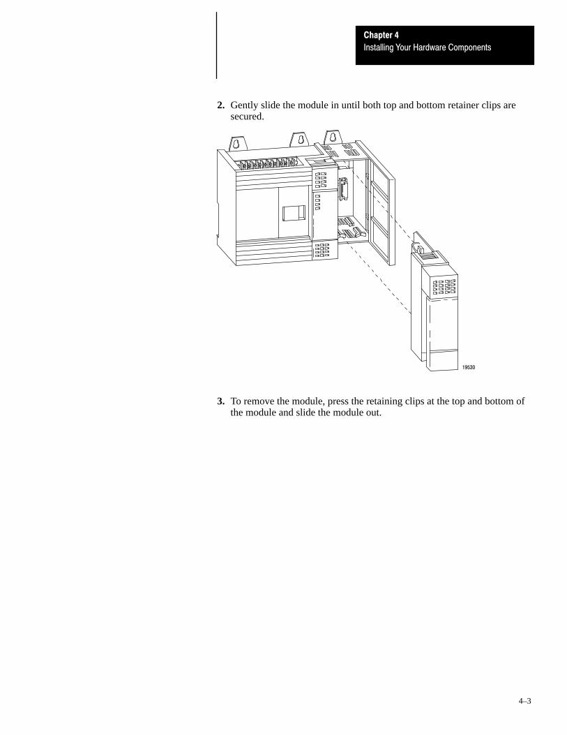
Chapter 4
Installing Your Hardware Components
4–3
2. Gently slide the module in until both top and bottom retainer clips aresecured.
19530
3. To remove the module, press the retaining clips at the top and bottom ofthe module and slide the module out.

Chapter 4
Installing Your Hardware Components
4–4
Always turn off power to the controller before inserting or removing thememory module. This guards against possible damage to the module andalso undesired processor faults. Memory modules are mounted in carriersand have connectors that are “keyed” to guard against improper installation.
!ATTENTION: To avoid potential damage to the memorymodules, handle them by the ends of the carrier or edges of theplastic housing. Skin oil and dirt can corrode metallic surfaces,inhibiting electrical contact. Also, do not expose memorymodules to surfaces or areas that may hold an electrostaticcharge. Electrostatic charges can alter or destroy memory.
1. Always turn off power to the controller before inserting or removing thememory module. This guards against possible damage to the module andalso undesired processor faults.
!ATTENTION: When power is applied to the controllerhazardous electrical potentials exist under the front cover. Seepage 2–8 for more information.
2. Remove the processor compartment cover.
3. Locate the socket on the PC board.
Socket
4. Position the module correctly over the socket and press it firmly in place.(The memory module is keyed.)
1747-M1, -M2, -M3
5. Replace the cover on the SLC controller and restore power.
Installing Your Memory Module
Chapter 4
Installing Your Hardware Components
4–5
Removing Your Memory Module
To remove a memory module use the following procedure:
1. Remove the power from the fixed I/O unit.
2. Remove the processor compartment cover.
3. Grasp the carrier tabs with the thumb and index fingers, then gently butfirmly lift upwards on either end of the memory module carrier.
4. When the end is partially raised, begin lifting the other end in the samemanner. Repeat this until the memory module has been completelyremoved from the socket.
5. Replace processor cover.
The fixed I/O units that have 24 VDC input circuits are also equipped with ahigh–speed counter. The counter is capable of counting at a rate of up to 8 kHz.
You have the option of using input 0 as a normal input or as a high–speedcounter. To accommodate this dual function the input is equipped with ajumper selectable filter. You must cut the jumper for high–speed counteruse. A shielded cable is recommended to reduce noise to the input.
High-Speed Counter Operation
For high–speed counter operation do the following:1. Turn off power to the fixed controller.
!ATTENTION: When power is applied to the controllerhazardous electrical potentials exist under the front cover. Seepage 2–8 for more information.
2. Remove the SLC 500 cover.
3. Locate and cut jumper wire J2. The jumper is either beneath or to theright of the battery connector, as shown below. Do not removecompletely but make certain that the ends of the cut jumper wire are nottouching each other.
Using the High-Speed Counter

Chapter 4
Installing Your Hardware Components
4–6
beneath the battery connector OR to the right of the battery connector.
J2J2
The High-Speed Counter jumper is located either
4. Replace the cover.
High-Speed Counter Input Compatibility
The high–speed counter input circuit has the following characteristics:
• nominal input impedance of ≈ 1200 Ω• on–state voltage of 10–30 VDC• nominal input current draw of 20mA• minimum pulse width of 62.5 µsec.
Your input device or encoder must be single–ended and be compatible withthe specifications of the high–speed counter input. See the table below formore information.
For an Input Device or Encoder that Is Use an HSC Input Circuit that Is
Sourcing Sinking
Open Collector/ Sinking Sourcing
Open Collector with Pull-up Resistor Sinking

Chapter 4
Installing Your Hardware Components
4–7
Wiring Diagram of a High-Speed Counter Sinking Input Circuit
DCCOM
IN 1 IN 3
CHASSISGND
DCCOM
IN 0HSC
IN 2
IN 5
IN 4
- +
Shielded Twisted PairBelden or Equivalent
1030 VDC
Sourcing Input Device
Wiring Diagram of a High-Speed Counter Sourcing Input Circuit
VDC IN 1 IN 3
CHASSISGND
VDC IN 0HSC
IN 2
IN 5
IN 4
-+
Shielded Twisted PairBelden or Equivalent
1030 VDC
Sinking Input Device


5Chapter
5–1
Wiring Your Control System
This chapter describes how to wire your I/O modules. It covers thefollowing:
• defining sinking and sourcing• determining approximate transient duration• preparing your wiring layout• features of an I/O module• recommendations for wiring I/O devices• wiring your I/O modules• using Removable Terminal Blocks (RTBs)
Sinking and sourcing are terms used to describe a current signal flowrelationship between field input and output devices in a control system andtheir power supply.
• Field devices connected to the positive side (+V) of the field powersupply are sourcing field devices.
• Field devices connected to the negative side (DC Common) of the fieldpower supply are called sinking field devices.
To maintain electrical compatibility between field devices and theprogrammable controller system, this definition is extended to theinput/output circuits on the discrete I/O modules.
• Sourcing I/O circuits supply (source) current to sinking field devices.• Sinking I/O circuits receive (sink) current from sourcing field devices.
Defining Sinking andSourcing

Chapter 5
Wiring Your Control System
5–2
Contact Output Circuits AC or DC
Relays can be used for either AC or DC output circuits and accommodateeither sinking or sourcing field devices. These capabilities are a result of theoutput switch being a mechanical contact closure, not sensitive to currentflow direction and capable of accommodating a broad range of voltages.
This high degree of application flexibility makes contact output modulesvery popular and useful in control environments with a broad mix ofelectrical I/O circuit requirements.
Solid-State DC I/O Circuits
The design of DC field devices typically requires that they be used in aspecific sinking or sourcing circuit depending on the internal circuitry of thedevice.
Sourcing Device with Sinking Input Module Circuit
The field device is on the positive side of the power supply between thesupply and the input terminal. When the field device is activated, it sourcescurrent to the input circuit.
DC POWERSUPPLY
+
_
FIELD DEVICEInput
DC Com
DCINPUTCIRCUIT
I
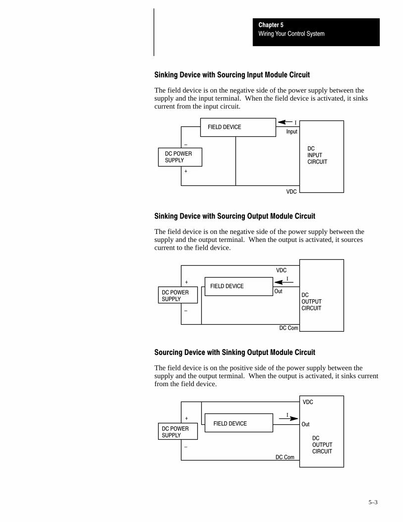
Chapter 5
Wiring Your Control System
5–3
Sinking Device with Sourcing Input Module Circuit
The field device is on the negative side of the power supply between thesupply and the input terminal. When the field device is activated, it sinkscurrent from the input circuit.
DC POWERSUPPLY
+
_
Input
VDC
DCINPUTCIRCUIT
IFIELD DEVICE
Sinking Device with Sourcing Output Module Circuit
The field device is on the negative side of the power supply between thesupply and the output terminal. When the output is activated, it sourcescurrent to the field device.
DC POWERSUPPLY
+
_
VDC
DC Com
DCOUTPUTCIRCUIT
I
OutFIELD DEVICE
Sourcing Device with Sinking Output Module Circuit
The field device is on the positive side of the power supply between thesupply and the output terminal. When the output is activated, it sinks currentfrom the field device.
DC POWERSUPPLY
+
_
VDC
DC Com
DCOUTPUTCIRCUIT
I
OutFIELD DEVICE

Chapter 5
Wiring Your Control System
5–4
Careful wire routing within the enclosure helps to cut down electrical noisebetween I/O lines. Follow these rules for routing your wires:
• Route incoming power to the controller by a separate path from wiring toI/O devices. Where paths must cross, their intersection should beperpendicular.
Important: Do not run signal or communications wiring and powerwiring in the same conduit.
• If wiring ducts are used, allow for at least two inches between I/O wiringducts and the controller. If the terminal strips are used for I/O wiring,allow for at least two inches between the terminal strips and thecontroller.
• Segregate I/O wiring by signal type. Bundle wiring with similar electricalcharacteristics together.
Wires with different signal characteristics should be routed into the enclosureby separate paths.
!ATTENTION: If the controller is being installed within apotentially hazardous environment (that is, Class I, Division 2),all wiring must comply with the requirements stated in theNational Electrical Code 501–4 (b).
Preparing Your Wiring Layout
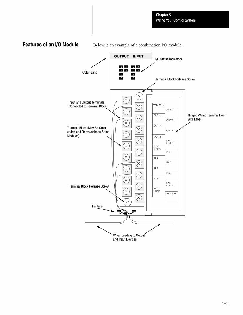
Chapter 5
Wiring Your Control System
5–5
Below is an example of a combination I/O module.
Input and Output TerminalsConnected to Terminal Block
I/O Status Indicators
Terminal Block Release Screw
HSCE
OUT 1
OUT 3
OUT 0
OUT 2
Terminal Block (May Be Color-coded and Removable on SomeModules)
Hinged Wiring Terminal Doorwith Label
OUTPUT INPUT
Tie Wire
OUT 5
NOTUSED
IN 5
OUT 4
IN 0
AC COM
NOTUSED
NOTUSED
NOTUSED
IN 4
IN 3
IN 2
IN 1
1
2
3
4
5
0
1
2
3
4
5
0
VAC–VDC
Wires Leading to Outputand Input Devices
Color Band
Terminal Block Release Screw
Features of an I/O Module
Chapter 5
Wiring Your Control System
5–6
The following are general recommendations for wiring I/O devices.
!ATTENTION: Before you install and wire I/O devices,disconnect power from the controller and any other source to theI/O devices.
Use acceptable wire gauge — The I/O wiring terminals are designed toaccept #14 or smaller AWG stranded wires, and two wires per terminal(maximum). Maximum torque 0.9 N–m (8 in–lb).
Label wires — Label wiring to I/O devices, power sources, and ground. Usetape, shrink–tubing, or other dependable means for labeling purposes. Inaddition to labeling, use colored insulation to identify wiring based on signalcharacteristics. For example, you may use blue for DC I/O wiring and redfor AC I/O wiring.
Bundle wires — Bundle wiring for each similar I/O device together. If youuse ducts, allow at least 5 cm (2 in.) between the ducts and the controller sothere is sufficient room to wire the devices.
Identify terminals — Terminal cover plates have a write–on area for eachterminal. Use this area to identify your I/O devices. Label the RemovableTerminal Block (RTB) with appropriate slot, rack (chassis) and moduleidentification if you have not already. Refer to page 5–8 for moreinformation.
!ATTENTION: Calculate the maximum possible current in eachpower and common wire. Observe all local electrical codesdictating the maximum current allowable for each wire size.Current above the maximum ratings may cause wiring tooverheat, which can cause damage.
Capacitors on input modules have a stored charge that can causea non–lethal shock. Avoid mounting the controller in a positionwhere installation or service personnel would be in danger fromstartle reaction.
Recommendations for WiringI/O Devices

Chapter 5
Wiring Your Control System
5–7
Terminals on the modules have self–lifting pressure plates that accept two#14 AWG wires. Series B 12–point and 16–point and analog modules areequipped with removeable terminal blocks (RTBs) for ease of wiring. Formore information on using RTBs, see the next section.
LED indicators on the front of each module display the status of each I/Opoint. The LED indicators turn on when the proper signal to an inputterminal is applied or when the processor commands an output to beenergized.
To locate the I/O module wiring diagrams, contact your Allen–Bradley salesoffice for the latest product data entitled Discrete Input and Output Modules,Publication Number 1746–2.35. Or, locate the installation instruction sheetthat was sent with your I/O module; it also includes I/O wiring diagrams.
1. Install a wire tie to secure your wiring and keep it neat. (If you feed thetie into one hole, it will be routed back out through the other.)
OUTPUT INPUT
Tie Wire
123
45
0123
45
0
Wires Leading to Outputand Input Devices
2. Cover any unused slots with card slot fillers, Catalog Number 1746–N2,to keep the chassis free from debris and dust.
Wiring Your I/O Modules

Chapter 5
Wiring Your Control System
5–8
Removable Terminal Blocks (RTBs) are provided on all 12–point and16–point discrete I/O modules and analog modules. RTBs can only be usedwith these modules in the 2–slot expansion chassis. RTBs allow for fasterand more convenient wiring of the I/O modules. The modules and RTBs arecolor–coded as follows:
Color Type of I/O Removable Terminal Block
Red AC inputs/outputs
Blue DC inputs/outputs
Orange relay outputs
Green specialty modules
Replacement terminal blocks are available if they are lost or damaged. Seethe replacement part list in chapter 9.
Removing RTBs
Below are guidelines for removing the I/O RTBs.
!ATTENTION: Never install or remove I/O modules or terminalblocks while the SLC is powered.
1. If the I/O module is already installed in the chassis, remove power to theSLC.
2. Unscrew the upper right and lower left terminal block release screws.
3. Grasp the RTB with your thumb and forefinger and pull straight out.
4. Label the RTB with appropriate slot, rack (chassis) and moduleidentification.
SLOT______RACK______
• MODULE______Dot indicates terminal number 0(or top of I/O wiring).
Terminal Block Release Screw
Terminal Block Release Screw
Using Removable TerminalBlocks (RTBs)

Chapter 5
Wiring Your Control System
5–9
Installing RTBs
Below are guidelines for installing the I/O RTBs.
1. Label the RTB properly.
2. Match the label identification to the correct chassis, slot, and moduletype.
!ATTENTION: Inserting a wired RTB on an incorrect modulecan damage the I/O module circuitry when power is applied.
3. Be sure the color band on the I/O module matches the color of the RTB.
!ATTENTION: Never install or remove I/O modules or RTBswhile the SLC 500 chassis is powered.
4. Remove power from the SLC 500 chassis.
5. Line up terminal block release screws.
6. Press the RTB firmly onto connector contacts.
7. Tighten the RTB release screws.


6Chapter
6–1
Starting Up Your Control System
This chapter describes how to start up your control system. To accomplishthis, you must go through eight procedures.
Start–up involves the following procedures to be carried out in sequence:
1. Inspect your installation.
2. Disconnect motion–causing devices.
3. Initialize and test your processor.
4. Test your inputs.
5. Test your outputs.
6. Enter and test your program.
7. Observe control motion.
8. Conduct a dry run of your application.
These procedures isolate problems such as wiring mistakes, equipmentmalfunction, and programming errors in a systematic, controlled manner.
We urge you to go through these procedures very carefully. This will helpyou avoid possible personal injury and equipment damage.
Important: Do not attempt system start–up until you are thoroughlyfamiliar with the controller components andprogramming/editing techniques. You must also be thoroughlyfamiliar with the particular application.
For general recommendation concerning installation safety requirements andsafety requirements and safety related work practices, refer to NFPA 70E,Electrical Safety Requirements for Employee Workplaces.
Procedures for Starting Upthe Control System
Chapter 6
Starting Up Your Control System
6–2
You can often prevent serious problems in later test procedures by firstmaking a thorough physical inspection. We recommend that you do thefollowing:
1. Make sure that the controller and all other devices in the system aresecurely mounted. Refer to chapter 3 and chapter 4 for more information.
2. Check all wiring including:
• connections from the main disconnect to the controller input• the master control relay/emergency–stop circuit• input device circuits• output device circuits
Make certain that all wiring connections are correct and that there are nomissing wires. Check the tightness of all terminals to make certain wiresare secure. Refer to chapter 5 for more information.
3. Measure the incoming line voltage. Be certain that it corresponds tocontroller requirements and that it falls within the specified voltage range.See specifications for input voltage ranges in chapter 1.
In the following test procedures, the controller will be energized. As a safetyprecaution, you must make certain that machine motion will not occur. Thepreferred way is to disconnect the motor wires at the motor starter or themotor itself. In this way, you can test the operation of the starter coil,verifying that your output circuit is wired correctly and functioning.Similarly, the preferred way to disconnect a solenoid is to disengage thevalve, leaving the coil connected.
In some instances, you may not be able to disconnect a device the preferredway. In this case, it will be necessary to open the output circuit at someconvenient point.
For circuit testing purposes, it is best to open the circuit at a point as close aspossible to the motion–causing device. For example, your output might be arelay coil that in turn energizes a motor starter; if it is impractical todisconnect the motor wires, the next best thing to do is to open the circuit at apoint between the motor starter and the relay contact.
!ATTENTION: Machine motion during system checkout can behazardous to personnel. During the checkout procedures 3, 4, 5,and 6, you must disconnect all devices that, when energized,might cause machine motion.
1. Inspect Your Installation
2. Disconnect Motion-causing Devices

Chapter 6
Starting Up Your Control System
6–3
When you are certain that machine motion cannot occur with the controllerenergized, you may begin by initializing the processor using the followingsteps:
1. Energize the controller. If power is supplied to the controller and theinstallation is correct, then:A. The POWER LED turns on as shown in the figure below.
Indicates the LED is OFF.
Indicates the LED is ON.
BATTERY LOW
FORCED I/O
CPU FAULT
PC RUN
POWER
The CPU FAULT LED also turns on during power–up, but it shouldgo off after a few seconds. If instead this LED starts flashing, itindicates you must clear the processor memory before continuing.
B. The following processor initial factory conditions apply:• Mode = PROGRAM MODE
(S:1/0 – S:1/4 = 0 0001)• Watchdog values = 100ms
(S:3H = 0000 1010)• I/O Slot enables = ALL ENABLED
(S:11/1 through S:12/14 set to 1)• Node address = 1
(S:15L = 0000 0001)• Baud Rate = 19.2K baud
(S:15H = 0000 0100)• Processor Name = DEFAULT
2. Power up the programming device.
Refer to the Hand–Held Terminal User Manual, Catalog Number1747–NP002, for information on programming your fixed controller withthe HHT.
Refer to the Advanced Programming Software User Manual, CatalogNumber 1747–NM002 Series C, and the Advanced ProgrammingSoftware Reference Manual, Catalog Number 1747–NR001, forinformation on programming your fixed controller with APS.
3. Configure the controller.
4. Name the processor file.
5. Program a sample test rung not affecting machine operation.
6. Save the program and the controller configuration.
3. Initialize and Test Your Processor
Chapter 6
Starting Up Your Control System
6–4
7. Transfer the controller configuration and the sample test program to theprocessor. After the new program is transferred to the processor, theprocessor fault status should clear. (The CPU FAULT LED stops if it wasflashing.)
8. Enter the Run mode.
The processor PC RUN LED should turn on indicating the controller is inthe RUN mode with no processor faults. If any other processor statusexists, refer to chapter 8.
9. Monitor the sample test rung.
If the sample test rung operates successfully without processor faults, youhave verified that basic processor functions are properly functioning. Ifany other processor status exists, refer to chapter 8.
After successful processor initialization and test, you may begin testinginputs following these steps:
1. Assuming you are still online with the programming device, put thecontroller into the Continuous Test mode. This allows the processor toscan the I/O and program, but not turn on any physical outputs.
2. Monitor the data in data File 1, the input data file. All configured inputsshould be displayed.
3. Make sure the first input slot, slot 0, is shown on the monitor.
4. Select the first input device connected to Input 0 of the fixed I/O chassis.
5. Manually close and open the addressed input device.
!ATTENTION: Never reach into a machine to actuate a device,unexpected machine operation could occur.
4. Test Your Inputs

Chapter 6
Starting Up Your Control System
6–5
6. Observe the associated bit status using the programming device monitorfunction. Also, observe the input status LED on the fixed I/O chassis.
A. When the input device is closed verify that the voltage at the inputterminal is within the specified on–state range, the input status LED ison, and the associated status bit is set to a one.
If any of these conditions are not satisfied, follow the recommendedtroubleshooting steps listed below.
B. When the input device is opened verify that the voltage at the inputterminal is within the specified off–state range, the input status LED isoff, and the associated status bit is reset to 0.
If any of these conditions are not satisfied, follow the recommendedtroubleshooting steps listed below.
7. Select the next input device and repeat steps 5 and 6 until all inputs on thefixed I/O chassis and in the 2–slot expansion rack (if used) have beentested.
Input Troubleshooting Steps
1. Make sure the processor is in the Continuous Test mode.
2. Verify that your inputs and outputs are enabled. Status file bit S:11/0represents the inputs and outputs of the fixed controller. Status file bitsS:11/1 and S:11/2 represent the inputs and outputs (slot 1 and slot 2respectively) of the 2–slot expansion chassis. These bits must be set toone, enabling all your inputs and outputs.
3. Check your wiring and verify that all connections are tight.
A. Make sure that power connections have been made to your inputdevice if needed.
B. Verify that the signal connection has been made from the input deviceto the correct input circuit of the fixed controller.
C. Check that all common connections have been made.
4. Check your specifications.
A. Make sure that the power is within the specified voltage range if yourinput device requires power.
B. Verify that your power supply is not overloaded. An overloadedsupply can deliver the correct voltage when some of its loads are notenergized but the voltage may fall out of range when all of its loadsare energized.
C. Verify that your input device signal contact is specified to deliversufficient current to the input circuit and any other loads connected toit.
D. Make certain that your input device does not have a minimum loadspecification that is greater than the input circuit current specification.
E. Verify that the input device is on and off longer than the specifiedturn–on and turn–off times for the input circuit.
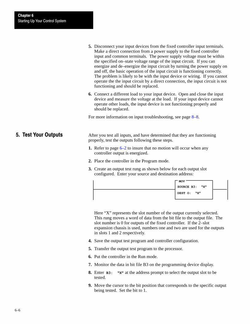
Chapter 6
Starting Up Your Control System
6–6
5. Disconnect your input devices from the fixed controller input terminals.Make a direct connection from a power supply to the fixed controllerinput and common terminals. The power supply voltage must be withinthe specified on–state voltage range of the input circuit. If you canenergize and de–energize the input circuit by turning the power supply onand off, the basic operation of the input circuit is functioning correctly.The problem is likely to be with the input device or wiring. If you cannotoperate the the input circuit by a direct connection, the input circuit is notfunctioning and should be replaced.
6. Connect a different load to your input device. Open and close the inputdevice and measure the voltage at the load. If your input device cannotoperate other loads, the input device is not functioning properly andshould be replaced.
For more information on input troubleshooting, see page 8–8.
After you test all inputs, and have determined that they are functioningproperly, test the outputs following these steps.
1. Refer to page 6–2 to insure that no motion will occur when anycontroller output is energized.
2. Place the controller in the Program mode.
3. Create an output test rung as shown below for each output slotconfigured. Enter your source and destination address:
MOV
SOURCE B3: “X”
DEST O: “X”
Here “X” represents the slot number of the output currently selected.This rung moves a word of data from the bit file to the output file. Theslot number is 0 for outputs of the fixed controller. If the 2–slotexpansion chassis is used, numbers one and two are used for the outputsin slots 1 and 2 respectively.
4. Save the output test program and controller configuration.
5. Transfer the output test program to the processor.
6. Put the controller in the Run mode.
7. Monitor the data in bit file B3 on the programming device display.
8. Enter B3: “X” at the address prompt to select the output slot to betested.
9. Move the cursor to the bit position that corresponds to the specific outputbeing tested. Set the bit to 1.
5. Test Your Outputs

Chapter 6
Starting Up Your Control System
6–7
10.Observe the output status LED and the output device.The output status LED should turn on. The output device should beenergized unless you disconnected it to prevent machine motion. It maybe necessary to connect a dummy load to the output to complete this test.If the LED does not turn on or if the load is not energized, follow theoutput troubleshooting steps listed below.
11.Reset the bit value back to zero for the selected address. Both the outputstatus LED and the output device should de–energize. If the LED doesnot turn off or if the load does not de–energize, follow the outputtroubleshooting steps listed below.
12.Repeat steps 9 through 11 for all outputs of the selected slot.
13.Repeat steps 8 through 12 for all slots (with outputs) that are a part of thefixed controller configuration.
Output Troubleshooting Steps
1. Make sure the processor is in the Run mode.
2. Verify that the test rung recommended in the previous section has beenentered correctly.
3. Check the status file I/O slot enable bits. Status file bit S:11/0 representsthe inputs and outputs of the fixed controller. Status file bits S:11/1 andS:11/2 represent the inputs and outputs (slot 1 and slot 2 respectively) ofthe 2–slot expansion chassis. These bits must be set to one, enabling allyour inputs and outputs.
4. Use a programming device to verify that the bit being tested in the outputfile tracks the on/off status of the corresponding bit in the bit file.
If the output file does not track the bit file, but your program has beenentered correctly and the I/O are enabled, then your processor is notfunctioning properly and should be replaced.
If the output file tracks the bit file, then the processor is functioningproperly and the output command is being sent to either the I/O section ofthe fixed controller, or to the output module in the 2–slot expansionchassis.
5. Check the electrical connections.A. If the output being tested is in the 2–slot expansion chassis, verify that
the expansion chassis connector is properly mated to the expansionconnector of the fixed controller.
B. Turn off power to the I/O circuits. Verify that power and/or commonconnections are made to the proper output circuit terminals.
C. Verify that the power connections are made to the output load device ifthey are required.
D. Verify that the output terminal being tested is connected to the correcttermination point of the load device.
E. Check the tightness of all terminals to make certain that all wires aresecure.

Chapter 6
Starting Up Your Control System
6–8
6. Check your specifications.
A. Verify that all power supplies used are within the specified operatingranges of the I/O circuits and loads.
B. Check that the specified load current is greater than the minimum loadcurrent specified for the output circuit. (Leakage current from theoutput circuit may prevent you from turning off a low current load.)
C. Check that the specified load current is less than the maximum loadcurrent of the output circuit.
D. Make sure that the sum of all the load currents is equal to or less thanthe power supply capacity.
7. Restore power to the I/O circuits and test the output. If the precedingmeasures have not corrected the problem, turn off the I/O power anddisconnect the load. Connect the load directly to the I/O power supply.You should be able to operate the load by turning the power supply onand off.
If you can operate the load, and the load is within the specified operatingrange of the output circuit, the output circuit is not functioning properly.Replace the fixed controller or output module as necessary.
If you cannot operate the load by turning the power supply on and off, theload is not operating properly and it should be replaced.
For more information on output troubleshooting, refer to page 8–10.
After you test all inputs and outputs and they are functioning properly, werecommend the following steps to safely and successfully enter and test yourspecific application program. (For extra assistance, see the Hand–HeldTerminal User Manual or the Advanced Programming Software UserManual.)
1. Verify the offline program.
After the program has been entered in the offline edit file mode, program verification may begin.
Remaining in the offline edit file mode you may use the cursor keysand/or search function of your programming device to inspect everyinstruction and rung for errors.
2. Check your written program, rung for rung, against the program enteredinto the offline memory. The most common errors found in programentry are:
• incorrect addressing of instructions• omission of an instruction• more than one output instruction programmed using the same address
6. Enter and Test Your Program

Chapter 6
Starting Up Your Control System
6–9
3. Transfer the program into the processor.
A. Place your programming device online.
B. Place the processor in Program mode.
C. Select download function when using the Hand–Held Terminal or therestore function when using Advanced Programming Software.
4. Verify the online program transfer.
A. Select monitor file function.
B. Cursor through the program to verify that you selected the rightprogram.
5. Conduct a single–scan program test.
A. Select the monitor file function and place the cursor on the first rung.
B. Select the Test mode.
C. Select Single–Scan (SSN) test. In this test mode, the processorexecutes a single operating cycle, which includes reading the inputs,executing the ladder program, and updating all data without energizingthe output circuits. However, the monitor file function will identifythe output status as if the outputs were enabled.
Timers are also incremented a minimum of 10 milliseconds eachsingle scan.
D. Simulate the input conditions necessary to execute the currentmonitored rung of the program. If it is not practical to manuallyactivate the input device, use the force function to simulate the propercondition.
!ATTENTION: Never reach into a machine to actuate a device,unexpected machine operation could occur.
E. Activate a single operating scan as outlined in the programming deviceuser manual.
F. Verify the intended effects on the output instructions for that rung andoverall program logic effects.
G. Select the next program rung and repeat test procedures as listed aboveuntil the entire program has been tested.
6. Conduct a continuous scan program test.
Once the individual single scan rung tests have been completed andproper program operation verified, a continuous scan test might beappropriate before motion checkout.
This mode simulates the controller Run mode without energizing theexternal outputs.

Chapter 6
Starting Up Your Control System
6–10
Now that program execution has been verified, checkout of control motioncan begin. All persons involved with the programming, installation, layoutdesign, machine or process design, and maintenance should be involved inmaking decisions for determining the best and safest way to test the totalsystem.
The following procedures are general in nature. Individual conditions maywarrant their modification. The basic approach is to initiate testing with theleast amount of machine motion. Only some outputs are allowed to generatemachine motion. Then additional machine motion can be gradually added,thereby allowing any problems to be detected more easily under controlledconditions. The following procedure provides the steps for testing machinemotion using one output at a time.
!ATTENTION: During all phases of checkout, station a personready to operate an emergency–stop switch if necessary. Theemergency–stop switch will de–energize the master control relayand remove power from the machine. This circuit must behardwired only, it must not be programmed.
Use the following procedures:
1. Identify the first output device to be tested and reconnect its wiring.
!ATTENTION: Contact with AC line potential may cause injuryto personnel. When reconnecting wiring, make sure that ACpower disconnect switch is opened.
2. Place the controller in the Run mode and observe the behavior of theoutput device. To do this, simulate the input conditions necessary toenergize the output in the program. If it is not practical to manuallyactivate an input device, use the force function to simulate the properinput condition.
!ATTENTION: Never reach into a machine to actuate a device,unexpected machine operation could occur.
3. Repeat steps 1 and 2, testing each output device, one at a time.
7. Observe Control Motion
Chapter 6
Starting Up Your Control System
6–11
!ATTENTION: During all phases of the dry run test, station aperson ready to operate an emergency–stop switch if necessary.The emergency–stop switch will de–energize the master controlrelay and remove power from the machine. This circuit must behardwired only, it must not be programmed.
After thoroughly checking out the controller system and program, proceedwith a dry run of the application with all of the output devices enabled. Thisdry run will vary with the application. For example, a machine tool dry runmight test the program with all outputs enabled but without tooling an actualpart.
After you check out the entire system, and your dry run has been completedsatisfactorily, we recommend that you load your program into an EEPROMmemory module for back–up program storage. See chapter 3 for moreinformation. Refer to the Hand–Held Terminal User Manual, CatalogNumber 1747–NP002, or the Advanced Programming Software UserManual, Catalog Number 1747–NM002, for directions on loading theEEPROM from RAM.
This step completes the start–up procedures. Your SLC ProgrammableController is now ready for operation.
8. Conduct a Dry Run

7Chapter
7–1
Maintaining Your Control System
This chapter covers the following:
• handling, storing, and transporting battery, Catalog Number 1747–BA• installing or replacing your SLC 500 battery• replacing the power supply fuse• replacing retainer clips on a module
Refer to chapter 2 for important information on testing the master controlrelay circuit and preventive maintenance.
Follow the procedure below to ensure proper battery operation and reducepersonnel hazards.
Handling
• Use only for the intended operation.• Do not ship or dispose of batteries except according to recommended
procedures.• Do not ship on passenger aircraft.
!ATTENTION: Do not charge the batteries. An explosion couldresult or they could overheat causing burns.
Do not open, puncture, crush, or otherwise mutilate the batteries.A possibility of an explosion exists and/or toxic, corrosive, andflammable liquids would be exposed.
Do not incinerate or expose the batteries to high temperatures.Do not attempt to solder batteries. An explosion could result.
Do not short positive and negative terminals together. Excessiveheat could build up and cause severe burns.
Storing
Store the lithium batteries in a cool, dry environment, typically +20° C to+25° C (+68° F to +77° F) and 40% to 60% relative humidity. Store thebatteries and a copy of the battery instruction sheet in the original container,away from flammable materials.
Handling, Storing, andTransporting Battery, CatalogNumber 1747-BA

Chapter 7
Maintaining Your Control System
7–2
Transporting
One or Two Batteries – Each battery contains 0.23 grams of lithium.Therefore, up to two batteries can be shipped together within the UnitedStates without restriction. Regulations governing shipment to or within othercountries may differ.
Three or More Batteries – Procedures for the transportation of three ormore batteries shipped together within the United States are specified by theDepartment of Transportation (DOT) in the Code of Federal Regulations,CFR49, “Transportation.” An exemption to these regulations, DOT – E7052,covers the transport of certain hazardous materials classified as flammablesolids. This exemption authorizes transport of lithium batteries by motorvehicle, rail freight, cargo vessel, and cargo–only aircraft, providing certainconditions are met. Transport by passenger aircraft is not permitted.
A special provision of DOT–E7052 (11th Rev., October 21, 1982, par. 8–a)provides that:
“Persons that receive cell and batteries covered by this exemption mayreship them pursuant to the provisions of 49 CFR 173.22a in any of thesepackages authorized in this exemption including those in which they werereceived.”
The Code of Federal Regulations, 49 CRF 173.22a, relates to the use ofpackaging authorized under exemptions. In part, it requires that you mustmaintain a copy of the exemption at each facility where the packaging isbeing used in connection with shipment under the exemption.
Shipment of depleted batteries for disposal may be subject to specificregulation of the countries involved or to regulations endorsed by thosecountries, such as the IATA Restricted Articles Regulations of theInternational Air Transport Association, Geneva, Switzerland.
Important: Regulations for transportation of lithium batteries areperiodically revised.
!ATTENTION: Do not incinerate lithium batteries in generaltrash collection. Explosion or violent rupture is possible.Batteries should be collected for disposal in a manner to preventagainst short circuiting, compacting, or destruction of caseintegrity and hermetic seal.

Chapter 7
Maintaining Your Control System
7–3
For disposal, batteries must be packaged and shipped in accordance withtransportation regulations, to a proper disposal site. The U.S. Department ofTransportation authorizes shipment of “Lithium batteries for disposal” bymotor vehicle only in regulation 173.1015 of CRF49 (effective January 5,1983). For additional information contact:
U.S. Department of TransportationResearch and Special Programs Administration400 Seventh Street, S.W.Washington, D.C. 20590
Although the Environmental Protection Agency at this time has noregulations specific to lithium batteries, the material contained may beconsidered toxic, reactive, or corrosive. The person disposing of the materialis responsible for any hazard created in doing so. State and local regulationsmay exist regarding the disposal of these materials.

Chapter 7
Maintaining Your Control System
7–4
Back–up power for RAM is provided by a capacitor that will retain thecontents of the RAM for a period of 5 to 30 days. For applications requiringmemory back–up for a longer period of time an optional replaceable battery,Catalog Number 1747–BA, is required. The lithium battery providesback–up for approximately five years. A red BATTERY LOW LED turns onwhen the battery voltage has fallen below a threshold level.
For battery installation or replacement, do the following:1. Back up your ladder program.
2. Disconnect power to the processor.
!ATTENTION: When power is applied to the controllerhazardous electrical potentials exist under the front cover. Seepage 2–8 for more information.
3. Remove the processor cover.
4. If you are:installing a battery in a new processor (battery never installed before),remove the jumper from the battery socket. Store jumper in safe place forpossible future use without battery.
replacing an old battery, unplug the battery connector from the socket.The figure below shows you where to install the battery in a fixedcontroller.
5. Insert a new or replacement battery in the holder making sure it is held inby the retaining clip.
6. Plug the battery connector into the socket. See the figure below.
BatteryConnector
Retaining Clips
+
White Lead
Red Lead
Battery
7. Replace the cover.
Installing or Replacing YourSLC 500 Battery

Chapter 7
Maintaining Your Control System
7–5
Under normal power–up conditions, the POWER LED turns on. If a powersupply fuse is blown, the POWER LED will not turn on. One of thefollowing conditions could cause a blown power supply fuse:
• excessive line voltage• internal power supply malfunction• overloading 2–slot chassis
!ATTENTION: Contact with AC line potential can cause injuryto personnel. Remove system power before attempting fusereplacement.
Use only replacement fuses of the type and rating recommendedfor the unit. Improper fuse selection can result in equipmentdamage.
After the conditions causing the malfunction have been corrected, you canreplace the fuse:1. Disconnect power to the processor.
!ATTENTION: When power is applied to the controllerhazardous electrical potentials exist under the front cover. Seepage 2–8 for more information.
2. Remove the cover on the processor.
3. Locate the fuse. Use a miniature fuse puller to grip the fuse and remove itfrom its holder.
4. Discard the fuse and replace it with the recommended replacement fuse.(See chapter 9 for more information.)
Fuse
5. Replace the cover on the processor.
6. Restore power to the processor. The POWER LED should now turn on.
Replacing the Power SupplyFuse

Chapter 7
Maintaining Your Control System
7–6
If it becomes necessary to replace the retainer clip (also called self–lockingtab), order Catalog Number 1746–R15 (4 clips per package).
Retainer Clip
Holding Tabs
Removing Damaged Retainer Clips
If necessary, pry off the broken retainer clip from the bottom with ascrewdriver. Do not twist it off. You can damage the module.
Retainer Clip
Installing New Retainer Clips
Insert one of the pins of the retainer clip into the hole in the I/O module andthen snap the other end in place.
Replacing Retainer Clips onan I/O Module

8Chapter
8–1
Troubleshooting
In this chapter, you will learn about:
• calling Allen–Bradley for assistance• tips for troubleshooting your control system• troubleshooting your fixed controller• troubleshooting your input modules• troubleshooting your output modules
If you need to contact Allen–Bradley or your local distributor for assistance,it is helpful to obtain the following (prior to calling):
• processor type, series letter, and firmware (FRN) number (see label onside of processor module)
• processor LED status• processor error codes (found in S:6 of status file)• hardware types in system (I/O modules, chassis)• revision of programming device (on the main menu of the Hand–Held
Terminal or Advanced Programming Software)
Calling Allen-Bradley forAssistance

Chapter 8
Troubleshooting
8–2
When troubleshooting, pay careful attention to these general warnings:
!ATTENTION: Have all personnel remain clear of the controllerand equipment when power is applied. The problem may beintermittent and sudden unexpected machine motion could resultin injury. Have someone ready to operate an emergency–stopswitch in case it becomes necessary to shut off power to thecontroller equipment. Also, see NFPA 70E Part II for additionalguidelines for safety related work practices.
Never reach into a machine to actuate a switch since unexpectedmachine motion can occur and cause injury.
Remove all electrical power at the main power disconnectswitches before checking electrical connections or inputs/outputscausing machine motion.
If installation and start–up procedures detailed in chapters 3, 4, and 5 werefollowed closely, your SLC controller will give you reliable service. If aproblem should occur, the first step in the troubleshooting procedure is toidentify the problem and its source.
The SLC 500 controller has been designed to simplify troubleshootingprocedures. By observing the diagnostic indicators on the front of theprocessor unit and I/O modules, the majority of faults can be located andcorrected. These indicators, along with error codes identified in theprogramming device user manual and programmer’s monitor, help trace thesource of the fault to the user’s input/output devices, wiring, or the controller.
Removing Power
Before working on a SLC 500 fixed system, always remove the powersupply input power at the main power disconnect switch.
The POWER LED on the power supply indicates that DC power is beingsupplied to the chassis. This LED could be off when incoming power ispresent when the:
• fuse is blown• voltage drops below the normal operating range. Refer to chapter 1 for
more information.• power supply is defective
Tips for Troubleshooting YourControl System
Chapter 8
Troubleshooting
8–3
Replacing Fuses
When replacing a fuse, be sure to remove all power from the system.
Program Alteration
There are several causes of alteration to the user program, including extremeenvironmental conditions, Electromagnetic Interference (EMI), impropergrounding, improper wiring connections, and unauthorized tampering. If yoususpect the memory has been altered, check the program against a previouslysaved program on an EEPROM, UVPROM or Flash EPROM module.
To receive the maximum benefit of this troubleshooting section, werecommend you follow these steps:
1. Match your processor LEDs with the status LEDs located in the firstcolumn in the tables on the following pages.
2. Once the status LEDs are matched to the appropriate table, simply moveacross the table identifying error description and probable causes.
3. Follow the recommended action steps for each probable cause until thecause is identified.
4. If recommended actions do not identify the cause, contact your localAllen–Bradley sales office or distributor.
Troubleshooting Your FixedController

Chapter 8
Troubleshooting
8–4
Identifying Fixed Controller Errors
Refer to the following key to determine the status of the LED indicators:
Indicates the LED is OFF.
Indicates the LED is ON.
Indicates the LED is FLASHING.
The FollowingError Exists
Probable Cause Recommended Action
No Line PowerVerify proper line voltage and connections on the powerterminals.
Power Supply1. Check the incoming power fuse, check for proper
incoming power connections. Replace fuse.
InadequateSystem Power
Power SupplyFuse Blown
incoming power connections. Replace fuse.
2. If fuse blows again, replace the fixed controller.System Power
Power SupplyOverloaded
This problem can occur intermittently if power supply islightly overloaded when output loading and temperaturevaries. If you are using a 2-slot chassis, verify thecompatibility of the modules to prevent overloading thebackplane power.
The FollowingError Exists
Probable Cause Recommended Action
Processor Not inRun Mode
Either ImproperMode Selected orUser ProgramLogic Error
1. Verify selected processor mode.
2. If in program/test modes, attempt RUN mode entry.
3. Check user program logic for suspend instructions ifin suspend mode.
Refer to either the Hand-Held Terminal User Manual,Catalog Number 1747-NP002, or the AdvancedProgramming Software User Manual, Catalog Number1747-NM002.
Line Power Out ofOperating Range
1. Check incoming power connections.
2. Monitor for proper line voltage at the incoming powerconnections.
If the LEDs indicate:
POWER
PC RUN
CPU FAULT
FORCED I/O
BATTERY LOW
If the LEDs indicate:
POWER
PC RUN
CPU FAULT
FORCED I/O
BATTERY LOW

Chapter 8
Troubleshooting
8–5
The FollowingError Exists
Probable Cause Recommended Action
SystemInoperable, NoMajor CPUF lt D t t d
User ProgramLogic Error
Monitor logic in Run mode and verify desired I/O status.
Refer to either the Hand-Held Terminal User Manual ,Catalog Number 1747-NP002, or the AdvancedProgramming Software User Manual, Catalog Number1747-NM002.j
Faults DetectedDefective I/ODevices or I/OWiring
Test inputs and outputs according to I/O troubleshootingprocedures starting on page 8-8.
The FollowingError Exists
Probable Cause Recommended Action
CPU MemoryError
Cycle power.
CPU FaultFaulty MemoryModule
1. Remove power and then remove the memory modulefrom the controller.
2. Re-energize the controller.
If steady CPU FAULT LED changes to flashing, replace theexisting memory module with a replacement module.
Refer to chapter 4 for removing and installing memorymodules.
ProcessorFirmware InstalledIncorrectly
If upgrading the processor to a different firmware level,verify that the firmware chip orientation matches theupgrade kit directions.
Refer to the following key to determine the statusof the LED indicators:
Indicates the LED is OFF.
Indicates the LED is ON.
Indicates the LED is FLASHING.
If the LEDs indicate:
POWER
PC RUN
CPU FAULT
FORCED I/O
BATTERY LOW
If the LEDs indicate:
POWER
PC RUN
CPU FAULT
FORCED I/O
BATTERY LOW

Chapter 8
Troubleshooting
8–6
The FollowingError Exists
Probable Cause Recommended Action
Initial CPU FactoryPower-upCondition
1. Refer to chapter 6 and follow the start-up procedures.
2. Clear processor memory to get rid of the flashing CPUFAULT LED.
CPU MajorFault
Hardware/SoftwareMajor FaultDetected
Erratic repetitivepower cycling cancause a processormajor hardwarefault.
1. Monitor Status File Word S:6 for major error code.
2. Refer to either the Hand-Held Terminal User Manual,Catalog Number 1747-NP002, or the AdvancedProgramming Software User Manual, Catalog Number1747-NM002, for error codes and additionaltroubleshooting information.
3. Remove hardware/software condition causing fault.
4. Clear Status File S:1/13 major error bit, if set.
5. Clear Status File S:5 minor error bits, if set.
6. Clear Status File S:6 major error code (optional).
7. Attempt a processor Run mode entry.
If unsuccessful, repeat recommended action steps above.
The FollowingError Exists
Probable Cause Recommended Action
System doesnot operate perladder logic.
User Forced I/ODisablingOperation
1. Monitor program file online and identify forced I/O.
2. Disable appropriate forces and test system conditionsagain.
Refer to either the Hand-Held Terminal User Manual,Catalog Number 1747-NP002, or the AdvancedProgramming Software User Manual, Catalog Number1747-NM002.
Refer to the following key to determine the statusof the LED indicators:
Indicates the LED is OFF.
Indicates the LED is ON.
Indicates the LED is FLASHING.
If the LEDs indicate:
POWER
PC RUN
CPU FAULT
FORCED I/O
BATTERY LOW
If the LEDs indicate:
POWER
PC RUN
CPU FAULT
FORCED I/O
BATTERY LOW
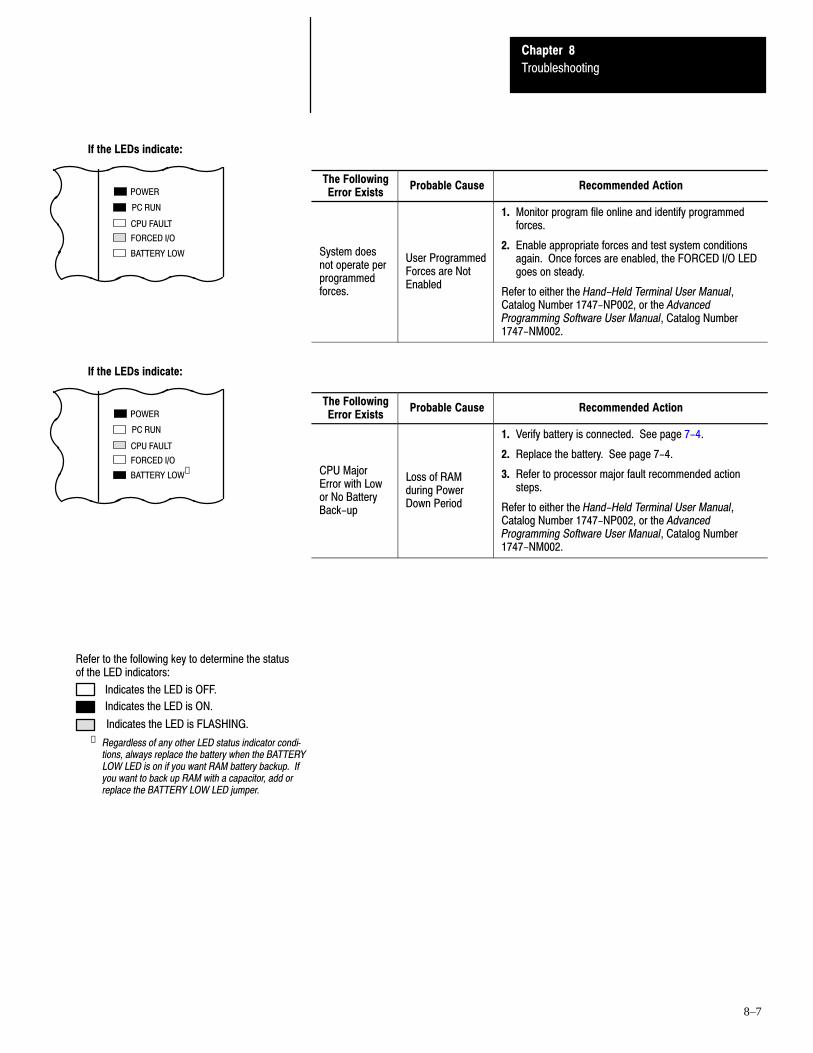
Chapter 8
Troubleshooting
8–7
The FollowingError Exists
Probable Cause Recommended Action
System doesnot operate perprogrammedforces.
User ProgrammedForces are NotEnabled
1. Monitor program file online and identify programmedforces.
2. Enable appropriate forces and test system conditionsagain. Once forces are enabled, the FORCED I/O LEDgoes on steady.
Refer to either the Hand-Held Terminal User Manual,Catalog Number 1747-NP002, or the AdvancedProgramming Software User Manual, Catalog Number1747-NM002.
The FollowingError Exists
Probable Cause Recommended Action
CPU MajorError with Lowor No BatteryBack-up
Loss of RAMduring PowerDown Period
1. Verify battery is connected. See page 7-4.
2. Replace the battery. See page 7-4.
3. Refer to processor major fault recommended actionsteps.
Refer to either the Hand-Held Terminal User Manual,Catalog Number 1747-NP002, or the AdvancedProgramming Software User Manual, Catalog Number1747-NM002.
Refer to the following key to determine the statusof the LED indicators:
Indicates the LED is OFF.
Indicates the LED is ON.
Indicates the LED is FLASHING.
Regardless of any other LED status indicator conditions, always replace the battery when the BATTERYLOW LED is on if you want RAM battery backup. Ifyou want to back up RAM with a capacitor, add orreplace the BATTERY LOW LED jumper.
➀
If the LEDs indicate:
POWER
PC RUN
CPU FAULT
FORCED I/O
BATTERY LOW
If the LEDs indicate:
POWER
PC RUN
CPU FAULT
FORCED I/O
BATTERY LOW➀
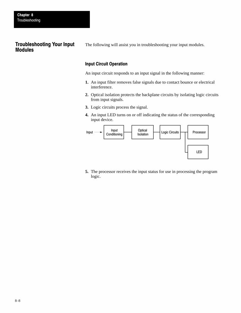
Chapter 8
Troubleshooting
8–8
The following will assist you in troubleshooting your input modules.
Input Circuit Operation
An input circuit responds to an input signal in the following manner:
1. An input filter removes false signals due to contact bounce or electricalinterference.
2. Optical isolation protects the backplane circuits by isolating logic circuitsfrom input signals.
3. Logic circuits process the signal.
4. An input LED turns on or off indicating the status of the correspondinginput device.
InputInput
ConditioningOptical Isolation
Logic Circuits Processor
LED
5. The processor receives the input status for use in processing the programlogic.
Troubleshooting Your InputModules

Chapter 8
Troubleshooting
8–9
Corrective Action
If your InputCircuit LED is
And Your InputDevice is
And Probable Cause Recommended Action
Your input device will not turnoff.
Device is shorted ordamaged.
Verify device operation. Replace device.
On/Closed/ActivatedYour program operates as
Input is forced off inprogram.
Check the FORCED I/O or FORCE LEDon processor and remove forces.Your program operates as
though it is off. Input circuit isdamaged.
Try other input circuit. Replace module.
On
Your program operates ash h i i d/ h i
Input device Off-stateleakage currentexceeds input circuitspecification.
Check device and input circuitspecifications. Use load resistor tobleed-off current.
Off/Open/Deactivatedp g p
though it is on and/or the inputcircuit will not turn off.
Input device is shortedor damaged.
Verify device operation. Replace device.
Input circuit is miswiredor damaged.
Verify proper wiring. Try other inputcircuit. Replace module.
Input circuit isincompatible.
Check specification and sink/sourcecompatibility (if DC input).
Low voltage across theinput.
Check the voltage across input circuitand check source voltage.
On/Closed/ActivatedYour program operates asthough it is off and/or the inputcircuit will not turn on
Incorrect wiring or anopen circuit.
Check wiring and COMmonconnections.
Off
circuit will not turn on.Input signal turn ontime too fast for inputcircuit.
Check timing specifications.
OffInput circuit isdamaged.
Verify proper wiring. Try other inputcircuit. Replace module.
Your input device will not turnon.
Input device is openedor damaged.
Verify operation. Replace device.
Off/Open/DeactivatedYour program operates asthough it is on
Input is forced on inprogram.
Check processor FORCED I/O orFORCE LED and remove forces. Verifyproper wiring. Try other input circuit.
though it is on.Input circuit isdamaged.
Verify proper wiring. Try other inputcircuit. Replace module.

Chapter 8
Troubleshooting
8–10
The following will assist you in troubleshooting your output modules.
Output Circuit Operation
An output circuit controls the output signal in the following manner:
1. The processor determines the output status.
2. Logic circuits maintain the output status.
3. An output LED indicates the status of the output signal.
4. Optical isolation separates logic and backplane circuits from field signals.
5. The output driver turns the corresponding output on or off.
ProcessorOptical
IsolationLogic Circuits Output Drivers
LED
Output
Troubleshooting Your OutputModules

Chapter 8
Troubleshooting
8–11
Corrective Action
If your OutputCircuit LED is
And Your OutputDevice is
And Probable Cause Recommended Action
On/Energized
Your programindicates that theoutput circuit is off orthe output circuit will
Programming problem.
Check for duplicate outputs and addresses using thesearch function.
If using subroutines, outputs are left in their last statewhen not executing subroutines.
Use the force function to force output off. If this doesnot force the output off, output circuit is damaged. If theoutput does force off, then check again forlogic/programming problem.
the output circuit willnot turn off.
Output is forced on in program.Check processor FORCED I/O or FORCE LED andremove forces.
On
Output circuit is damaged.
Use the force function to force the output off. If thisforces the output off, then there is a logic/programmingproblem. If this does not force the output off, the outputcircuit is damaged. Try other output circuit. Replacemodule.
Your output device
Low or no voltage across theload.
Measure the source voltage and check specifications.
Off/De-energized
Your output devicewill not turn on andthe program
Incorrect wiring or open circuit. Check wiring and COMmon connections.Off/De-energized the program
indicates that it ison.
Output device is incompatible.Check specifications and sink/source compatibility (ifDC output).o
Output circuit is damaged. Check wiring. Try other output circuit. Replace module.
Output device is incompatible. Check specifications.
Your output devicewill not turn off and
Output circuit Off-state leakagecurrent may exceed outputdevice specification.
Check specifications. Use load resistor to bleed offleakage current. See output specifications.
On/Energizedwill not turn off andthe programindicates that it isoff
Incorrect wiring.Check wiring. Disconnect from SLC and verify deviceoperation.
off.Output device is shorted ordamaged.
Verify device operation. Replace device.
Output circuit is damaged. Check wiring. Try other output circuit. Replace module.
Off
Off/De-energized
Your programindicates that theoutput circuit is on orthe output circuit will
Programming problem.
Check for duplicate outputs and addresses usingsearch function.
If using subroutines, outputs are left in their last statewhen not executing subroutines.
Use the force function to force output on. If this doesnot force the output on, output circuit is damaged. If theoutput does force on, then check again forlogic/programming problem.
the output circuit willnot turn on.
Output is forced off in program.Check processor FORCED I/O or FORCE LED andremove forces.
Output circuit is damaged.
Use the force function to force the output on. If thisforces the output on, then there is a logic/programmingproblem. If this does not force the output on, the outputcircuit is damaged. Try other output circuit. Replacemodule.


9Chapter
9–1
Replacement Parts
This chapter provides a list of replacement parts and a list of replacementterminal blocks for your SLC 500 controller.
This table provides a list of replacement parts and their catalog numbers.
Description Catalog Number
Pre-wired Interface Cable Available in 1.0m, 2.5m, and 5.0m lengths. 1492-CABLE➀ H
Replacement Fuses Five fuses per package. Orders must be for five fuses or multiples of five.
Replacement fuse for Fixed I/O AC units, MDL 1.25 Ampere 1746-F4
Replacement fuse for Fixed I/O DC units, MDL 1.6 Ampere 1746-F5
Modular Card Slot Fillers Two fillers per package. Orders must be for two fillers or multiples of two. 1746-N2
Connector Mating Connector for 32 Point user-made cable 1746-N3
Kit consisting of four replacement terminal covers and labels for 4, 8, 16 I/O modules 1746-R9
Replacement Cover for Specialty I/OTwo covers per package. Orders must be for two covers or multiples of two.
1746-R13
Replacement Retainer Clips for ModulesFour clips per package. Orders must be for four clips or multiples of four.
1746-R15
Lithium Battery AssemblyThis is an optional part used for the SLC 500 Fixed and Modular Hardware Style processors and the Hand-Held Terminal.Refer to product documentation for proper storage and handling instructions. For disposal information, consult your nearestAllen-Bradley Sales Office.
1747-BA
Processor to Peripheral Programming/Communication Cable 1747-C10
Processor to Isolated Link Coupler Cable 1747-C11
Specialty Module to Isolated Link Coupler Cable 1747-C13
EEPROM with 1K User Instructions 1747-M1
UVPROM with 1K User Instructions 1747-M3
Adapter Sockets Orders must be for five sockets or multiples of five. 1747-M5
Replacement Parts Kit for 20 I/O Fixed Hardware Style ProcessorTwo Output Terminal CoversTwo Input Terminal CoversTwo Prom/Battery CoversOne HHT/Comm Connector Cover
1747-R5
Replacement Parts Kit for 30 and 40 I/O Fixed Hardware Style ProcessorsTwo Output Terminal CoversTwo Input Terminal CoversTwo Prom/Battery CoversOne HHT/Comm Connector Cover
1747-R7
Replacement Terminal Covers for 4, 8, & 16 I/O ModulesThis kit contains four blank covers and appropriate labels for replacement of any required I/O module cover.
1747-R9
HHT Keypad Replacement Overlay for English Memory Pak Firmware Releases 1.02, 1.07 and 1.10 1747-R20
HHT Keypad Replacement Overlay for French Memory Pak Firmware Releases 1.10 1747-R20F
HHT Keypad Replacement Overlay for German Memory Pak Firmware Releases 1.10 1747-R20G
HHT Keypad Replacement Overlay for Italian Memory Pak Firmware Releases 1.10 1747-R20I
HHT Keypad Replacement Overlay for English Memory Pak Firmware Releases 2.00 and Later 1747-R21
HHT Keypad Replacement Overlay for French Memory Pak Firmware Releases 2.00 and Later 1747-R21F
➀ Insert the cable length code into the catalog number. Cable length codes are as follows: 10=1.0m, 25=2.5m, and 50=5.0m. For example, 1492-CABLE25H is a 2.5m cable.
Replacement Parts

Chapter 9
Replacement Parts
9–2
This table provides a list of replacement terminal blocks and their catalognumbers.
Description Catalog Number
Replacement Terminal Block (Red) Used with AC I/O modules, Catalog Numbers 1746-IA16, OA16, IM16 1746-RT25R
Replacement Terminal Block (Blue) Used with DC I/O modules, Catalog Numbers 1746-IB16, IV16, OB16, OV16, IN16,IG16, OG16
1746-RT25B
Replacement Terminal Block (Orange) Used with relay output modules, Catalog Numbers 1746-OW16, OX8 1746-RT25C
Replacement Terminal Block (Green) Used with Specialty I/O modules, Catalog Numbers 1746-HSCE, IO12 1746-RT25G
Replacement Terminal Block 2 position terminal block used with analog output modules, Catalog Numbers 1746-NO4I,NO4V
1746-RT26
Replacement Terminal Block 8 position terminal block used with analog output modules, Catalog Numbers 1746-NO4I,NO4V
1746-RT27
Replacement Terminal Block Used with analog input modules, Catalog Numbers 1746-NI4, NIO4I, NIO4V 1746-RT28
Replacement Terminal Block Used with RIO Communication Modules, Catalog Numbers 1747-SN, DSN, DCM 1746-RT29
Replacement Terminal Block Used with DH-485 Link Coupler, Catalog Number 1747-AIC 1746-RT30
Replacement Terminal Blocks

AAppendix
A–1
Setting Up the DH-485 Network
The information in this appendix will help you plan, install, and operate theSLC 500 in a DH–485 network. This chapter also contains information thatdescribes the DH–485 network functions, network architecture, andperformance characteristics. It also covers:
• DH–485 network description• DH–485 network protocol• DH–485 token rotation• DH–485 network initialization• devices that use the DH–485 network• 1747–AIC isolated link coupler for DH–485• example system configuration• important planning considerations• DH–485 network installation
We have designed the DH–485 network to pass information between deviceson the plant floor. The network monitors process parameters, deviceparameters, device status, process status and application programs to supportdata acquisition, data monitoring, program upload/download and supervisorycontrol.The DH–485 network offers:
• interconnection of 32 devices• multi–master capability• token passing access control• the ability to add or remove nodes without disrupting the network• maximum network length of 1219 m (4000 ft)
The following section describes the protocol used to control messagetransfers on the DH–485 network. The protocol supports two classes ofdevices: initiators and responders. All initiators on the network get a chanceto initiate message transfers. To determine which initiator has the right totransmit, a token passing algorithm is used.
DH-485 Network Description
DH-485 Network Protocol

Appendix A
Setting Up the DH-485 Network
A–2
A node holding the token can send any valid packet onto the network. Eachnode is allowed only one transmission (plus two retries) each time it receivesthe token. After a node sends one message packet, it attempts to give thetoken to its successor by sending a “token pass” packet to its successor.
If no network activity occurs, the initiator sends the token pass packet again.After two retries (a total of three tries) the initiator will attempt to find a newsuccessor.
Important: The maximum address that the initiator will search for beforewrapping to zero is the value in the configurable parameter“maximum node address.” The default value for this parameteris 31 for all initiators and responders.
The allowable range of the node address of an initiator is 0 to 31. Theallowable address range for all responders is 1 to 31. There must be at leastone initiator on the network.
Network initialization begins when a period of inactivity exceeding the timeof a link dead timeout is detected by an initiator on the network. When thetime for a link dead timeout is exceeded, usually the initiator with the lowestaddress claims the token. When an initiator has the token it will begin tobuild the network. The network requires at least one initiator to initialize it.
Building a network begins when the initiator that claimed the token tries topass the token to the successor node. If the attempt to pass the token fails, orif the initiator has no established successor (for example, when it powers up),it begins a linear search for a successor starting with the node above it in theaddressing.
When the initiator finds another active initiator, it passes the token to thatnode, which repeats the process until the token is passed all the way aroundthe network to the first node. At this point, the network is in a state ofnormal operation.
DH-485 Token Rotation
DH-485 Network Initialization

Appendix A
Setting Up the DH-485 Network
A–3
Presently, the following SLC 500 devices support the DH–485 network:
• SLC 500 Fixed I/O Controller (responder)• SLC 5/01 Modular I/O Controller (responder)• SLC 5/02 Modular I/O Controller (initiator/responder)• SLC 5/03 Modular I/O Controller (initiator/responder)• Personal computer running SLC 500 Advanced Programming Software
(initiator)• Hand–Held Terminal (initiator)• DTAM (initiator/responder)
Other devices that use the DH–485 network include those in the table below.
Catalog Number Description Installation Requirement Function Publication
1746-BAS BASIC Module SLC Chassis
Provides an interface for SLC 500devices to foreign devices. Program inBASIC to interface the 3 channels (2RS-232 and 1 DH485) to printers,modems, or the DH-485 network fordata collection.
1746-ND005
1746-NM002
1746-NM001
1747-KEDH-485/DF1Interface Module
SLC Chassis
Provides a non-isolated DH-485interface for SLC 500 devices to hostcomputers over RS-232 using full- orhalf-duplex DF1 protocol. Enablesremote programming with APS to anSLC 500 processor or the DH-485network through modems. Ideal for lowcost RTU/SCADA applications.
1747-NU001
1770-KF3DH-485/DF1Interface Module
Standalone (desktop")
Provides an isolated DH-485 interfacefor SLC 500 devices to host computersover RS-232 using full- or half-duplexDF1 protocol. Enables remoteprogramming with APS to an SLC 500processor or the DH-485 networkthrough modems.
1770-6.5.18
1784-KRPC DH-485Interface Module
IBM XT/ATComputer Bus
Provides an isolated DH-485 port on theback of the computer. When used withAPS software, it improvescommunication speed and eliminatesuse of the Personal Interface Converter(1747-PIC). The Standard Driver allowsyou to write C" programs for dataacquisition applications.
1784-2.23
6001-6.5.5
1785-KA5 DH+/DH485Gateway
(1771) PLC Chassis
Provides communication betweenstations on the PLC-5 (DH+) and SLC500 (DH-485) networks. Enablescommunication and data transfer fromPLC to SLC 500 on DH-485 network.Also enables APS programming or dataacquisition across DH+ to DH-485.
1785-6.5.5
1785-1.21
2760-RBFlexible InterfaceModule
(1771) PLC Chassis
Provides an interface for SLC 500 (usingprotocol cartridge 2760-SFC3) to otherA-B PLCs and devices. Threeconfigurable channels are available tointerface with Bar Code, Vision, RF,Dataliners, and PLC systems.
2760-ND001
Devices that Use the DH-485Network

Appendix A
Setting Up the DH-485 Network
A–4
The isolated link coupler (1747–AIC) is used to connect SLC 500 familydevices to the DH–485 network (as shown on page A–5). The couplerprovides a 6–position removable terminal block for connection to theDH–485 communication cable.
Network connections for the SLC 500 processor are provided by the CatalogNumber 1747–C11, 304.8 mm (12 in.) cable supplied with the link coupler.Network connections for peripheral devices, such as the Personal InterfaceConverter (1747–PIC), Data Table Access Module (1747–DTAM–E), orHand–Held Terminal (1747–PT1) are provided by the standard CatalogNumber 1747–C10 1.8 m (6 ft) cable supplied with each of those devices.
To protect connected devices, the coupler provides 1500 VDC isolationbetween the communications cable and the attached SLC 500 controller andperipheral devices (PIC, DTAM, or HHT).
The isolated link coupler can also be used to provide connectivity between aperipheral device (APS and PIC, HHT, or DTAM) for distances greater than1.8 m (6 ft) up to a maximum of 1219 m (4000 ft). Below is an example of a“remote” connection between a computer running APS and an SLC 500processor.
PIC >1.8 m (6 ft)
+24VDC
APS
1747-AIC 1747-AIC
1747-C11
1747-C10
1747-C10
NP1 NP1➀ provides +24 VDC for the1747-AIC.
➀ You can also use an NP2 desktop model.
1747-AIC Isolated LinkCoupler for DH-485

Appendix A
Setting Up the DH-485 Network
A–5
Below is an example of a DH–485 network.
SLC
500
20
poin
t
Dat
a Ta
ble
Fix
ed I/
O C
ontr
olle
r
SLC
500
5/0
2M
odul
ar I/
O C
ontr
olle
r
1747
–AIC
1747
–AIC
1747
–AIC
1747
–AIC
1747
–AIC
1747
–AIC
Isol
ated
SLC
500
5/0
3M
odul
ar I/
O C
ontr
olle
r
SLC
500
Han
d–H
eld
Term
inal
Alle
n–B
radl
ey 1
784–
T45
, T47
or c
ompa
tible
lapt
op
SLC
500
5/0
1M
odul
ar I/
O C
ontr
olle
r
DH
–485
Net
wor
k m
ax. l
engt
h 12
19 m
(4,
000
ft.)
1747
–PIC
Inte
rfac
e C
onve
rter
IBM
–PC
, XT,
or
com
patib
lew
ith 1
784–
KR
, DH
–485
PC
Inte
rfac
e
Acc
ess
Mod
ule
SLC
500
Fix
ed I/
O C
ontr
olle
r
Link
Cou
pler
Example System Configuration

Appendix A
Setting Up the DH-485 Network
A–6
Carefully plan your network configuration before installing any hardware.Listed below are some of the factors that can affect system performance:
• amount of electrical noise, temperature, and humidity in the networkenvironment
• number of devices on the network• connection and grounding quality in installation• amount of communication traffic on the network• type of process being controlled• network configuration
The major hardware and software issues you need to resolve before installinga network are discussed in the following sections.
Hardware Considerations
You need to decide the length of the communication cable, where you routeit, and how to protect it from the environment where it will be installed.
When the communication cable is installed, you need to know how manydevices are to be connected during installation and how many devices will beadded in the future. The following sections will help you understand andplan the network.
Number of Devices and Length of Communication Cable
You must install a link coupler (1747–AIC) for each node on the network. Ifyou plan to add nodes later, provide additional link couplers during the initialinstallation to avoid recabling after the network is in operation.
The maximum length of the communication cable is 1219 m (4000 ft). Thisis the total cable distance from the first node to the last node on the network.
Planning Cable Routes
Follow these guidelines to help protect the communication cable fromelectrical interference:
• Keep the communication cable at least five feet from any electric motors,transformers, rectifiers, generators, arc welders, induction furnaces, orsources of microwave radiation.
• If you must run the cable across power feed lines, run the cable at rightangles to the lines.
• If you do not run the cable through a contiguous metallic wireway orconduit, keep the communication cable at least 0.15 m (6 in) from acpower lines of less than 20 A, 0.30 m (1 ft) from lines greater than 20 A,but only up to 100 kVA, and 0.60 m (2 ft) from lines of 100 kVA or more.
• If you run the cable through a contiguous metallic wireway or conduit,keep the communication cable at least 0.08 m (3 in) from ac power linesof less than 20 A, 0.15 m (6 in) from lines greater than 20 A, but only upto 100 kVA, and 0.30 m (1 ft) from lines of 100 kVA or more.
Important PlanningConsiderations

Appendix A
Setting Up the DH-485 Network
A–7
Running the communication cable through conduit provides extraprotection from physical damage and electrical interference. If you routethe cable through conduit, follow these additional recommendations:
– Use ferromagnetic conduit near critical sources of electricalinterference. You can use aluminum conduit in non–critical areas.
– Use plastic connectors to couple between aluminum and ferromagneticconduit. Make an electrical connection around the plastic connector(use pipe clamps and the heavy gauge wire or wire braid) to hold bothsections at the same potential.
– Ground the entire length of conduit by attaching it to the buildingearth ground.
– Do not let the conduit touch the plug on the cable.– Arrange the cables loosely within the conduit. The conduit should
contain only serial communication cables.– Install the conduit so that it meets all applicable codes and
environmental specifications.
For more information on planning cable routes, see Industrial AutomationWiring and Grounding Guidelines, publication number 1770–4.1.
Software Considerations
Software considerations include the configuration of the network and theparameters that can be set to the specific requirements of the network. Thefollowing are major configuration factors that have a significant effect onnetwork performance:
• number of nodes on the network• addresses of those nodes• baud rate• maximum node address selection• 5/03 only: token hold factor
The following sections explain network considerations and describe ways toselect parameters for optimum network performance (speed).
Number of NodesThe number of nodes on the network directly affects the data transfer timebetween nodes. Unnecessary nodes (such as a second programming terminalthat is not being used) slow the data transfer rate. The maximum number ofnodes on the network is 32.

Appendix A
Setting Up the DH-485 Network
A–8
Setting Node Addresses
The best network performance occurs when node addresses start at 0 and areassigned in sequential order. SLC 500 processors default to node address 1.The node address is stored in the processor status file (S:15L). Processorscannot be node 0. Also, initiators such as personal computers should beassigned the lowest numbered addresses to minimize the time required toinitialize the network.
If some nodes are connected on a temporary basis, do not assign addresses tothem. Simply create nodes as needed and delete them when they are nolonger required.
Setting Processor Baud RateThe best network performance occurs at the highest baud rate, which is19200. All devices must be at the same baud rate. The default baud rate forSLC 500 devices is 19200. The baud rate is stored in the processor status file(S:15H).
Maximum Node Address Setting
The maximum node address parameter should be set as low as possible. Thisminimizes the amount of time used in soliciting successors when initializingthe network. If all nodes are addressed in sequence from 0, and themaximum node address is equal to the address of the highest addressed node,the token rotation will improve by the amount of time required to transmit asolicit successor packet plus the slot timeout value.
Note that this does not allow any node to be added to the network withoutaffecting the response time. On the other hand, since the time required tohold an open station address is greater than the time required to pass a token,it can be useful to leave a temporary device (such as a personal computer)connected if there is only one such device. (A solicit successor packetrequires the same transmission time as the token pass, but there is an addedslot timeout period.)
See the Hand–Held Terminal User Manual, Catalog Number 1747–NP002,or the Advanced Programming Software User Manual, Catalog Number1747–NM002, for the procedures to set node addresses, processor baud rate,and maximum node addresses.
Important: The SLC 500 Series A (only) processors set the maximum nodeaddress to 31 when power is cycled increasing initialization andresponse time of the network.

Appendix A
Setting Up the DH-485 Network
A–9
To install a DH–485 network, you will need tools to strip the shielded cableand to attach the cable and terminators to the isolated link coupler.Install the DH–485 network using the following tools (or equivalent):
Description Part Number Manufacturer
Shielded Twisted Pair Cable #9842 Belden
Stripping Tool 45-164 Ideal Industries
1/8 " Slotted Screwdriver NA NA
DH-485 Communication Cable and Isolated Link Coupler
The link coupler provides a connection for each node. The isolated linkcoupler electrically isolates the DH–485 communication interface from theprocessor and peripheral connections. Electrical–optical isolation isprovided to 1500 VDC.
The suggested DH–485 communication cable is Belden #9842 cable. Thecable is jacketed and shielded with two twisted wire pairs and a drain wire.
One pair provides a balanced signal line, and one wire of the other pair isused for a common reference line between all nodes on the network. Theshield reduces the effect of electrostatic noise from the industrialenvironment on the network communication.
DH-485 Network Installation

Appendix A
Setting Up the DH-485 Network
A–10
Installing the DH-485 Communication Cable
The communication cable consists of a number of cable segmentsdaisy–chained together. The total length of the cable segments cannotexceed 1219 m (4000 ft).
When cutting cable segments, make them long enough to route them fromone link coupler to the next with sufficient slack to prevent strain on theconnector. Allow enough extra cable to prevent chafing and kinking in thecable.
Link Coupler1747-AIC
Link Coupler1747-AIC
Link Coupler1747-AIC
Connector Connector Connector
Belden#9842
Belden#9842
Belden#9842
DH-485Interface
Peripheral
CPU
Power
DH-485Interface
Peripheral
CPU
DH-485Interface
Peripheral
CPU
Power Power
Important: We only recommend a network that is daisy–chained. Forexample, we do not recommend the following:
Connector
Connector
Connector
Belden#9842
Belden#9842
Belden#9842
Incorrect

Appendix A
Setting Up the DH-485 Network
A–11
Connecting the Communication Cable to the Isolated Link Coupler
Attach the terminal block of the link coupler to the Belden #9842 cable asshown below. Additional terminal blocks are available for replacement, seechapter 9.
Single Cable Connection
6 Termination
5 A
4 B
3 Common
2 Shield
1 Chassis Ground
White with Orange Stripes
Orange with White Stripes
Blue with White StripesDrain Wire
Shrink Tubing Recommended
Belden #9842
Multiple Cable Connection
to Successive Device
to Previous Device
19525

Appendix A
Setting Up the DH-485 Network
A–12
The table below shows wire/terminal connections for DH–485 connectors forold Belden #9842.
For this Wire/Pair Connect this Wire To this Terminal
Shield/Drain Non-jacketed Terminal 2 - Shield
Black/WhiteBlack Cut back - no connection➀
Black/WhiteWhite Terminal 3 - (Common)
Black/RedBlack Terminal 4 - (Data B)
Black/RedRed Terminal 5 - (Data A)
➀ To prevent confusion when installing the communication cable, cut back the black wire immediately after thethe insulation jacket is removed. This wire is not used by DH-485.
The table below shows wire/terminal connections for DH–485 connectors fornew Belden #9842.
For this Wire/Pair Connect this Wire To this Terminal
Shield/Drain Non-jacketed Terminal 2 - Shield
Blue/WhiteWhite with Blue Stripe Cut back - no connection➀
Blue/WhiteBlue with White Stripe Terminal 3 - (Common)
White/OrangeWhite with Orange Stripe Terminal 4 - (Data B)
White/OrangeOrange with White Stripe Terminal 5 - (Data A)
➀ To prevent confusion when installing the communication cable, cut back the white with blue stripe wireimmediately after the the insulation jacket is removed. This wire is not used by DH-485.
Important: In Series A 1747–AIC, terminal 5 was called DATA B andterminal 4 was called DATA A. In this case, use terminalnumbers only and ignore signal names DATA B and DATA A.The internal circuitry of the Series A is the same as Series B.

Appendix A
Setting Up the DH-485 Network
A–13
Grounding and Terminating the DH-485 Network
One (only one) of the link couplers at the end of the link must haveTerminals 1 and 2 of the network connector jumpered together. Thisprovides an earth ground connection for the shield of the communicationcable.
Link couplers at both ends of the network must have Terminals 5 and 6 of thelink connectors jumpered together. This connects the termination impedance(of 120Ω) that is built into each link coupler as required by the DH–485specification. See the figure below for the proper jumpering.
End-of-Line Termination
Belden #9842 Cable(1219 m) 4000 ft Maximum
Jumper
Jumper
Jumper
1
2
3
4
5
6
1
2
3
4
5
6
Appendix A
Setting Up the DH-485 Network
A–14
Powering the Link Coupler
In normal operation with the programmable controller connected to the linkcoupler, the processor powers both the link coupler and peripheral device(DTAM, PIC, HHT) — if connected — through the C11 cable.
If you do not connect the processor to the link coupler, then use a 24 VDCpower supply to power the link coupler and peripheral device. The1747–AIC requires 85mA at 24 VDC. With a peripheral device connected,the total current required is 190mA at 24 VDC.
If both the processor and external power are connected to the link coupler,only the external source is used.
Important: Always connect the CHS GND (chassis ground) terminal to thenearest earth ground. This connection must be made whether ornot an external 24 VDC supply is used.
Below are three options for externally powering the 1747–AIC:
• If the link coupler is to be installed in an office environment, you can usethe wall mount power supply (1747–NP1) or global desktop power supply(1747–NP2). The link coupler would be powered through either the1747–C10 cable or by hardwiring from the supply to the screw terminalson the link coupler.
• If you use the AC chassis power supplies (1746–P1 or 1746–P2), you canuse the 24 VDC user power supply (200mA maximum) built into thepower supply. The link coupler would be powered through a hard–wiredconnection from the screw terminals on the power supply to the screwterminals on bottom of the link coupler.
• You can use an external DC power supply with the followingspecifications:– operating voltage: 24 VDC + 25%– output current: 190mA– rated NEC
The link coupler would be powered through a hard–wired connectionfrom the external supply to the screw terminals on the bottom of the linkcoupler.
!ATTENTION: If you use an external power supply, it must be24 VDC. Permanent damage will result if miswired with thewrong power source.
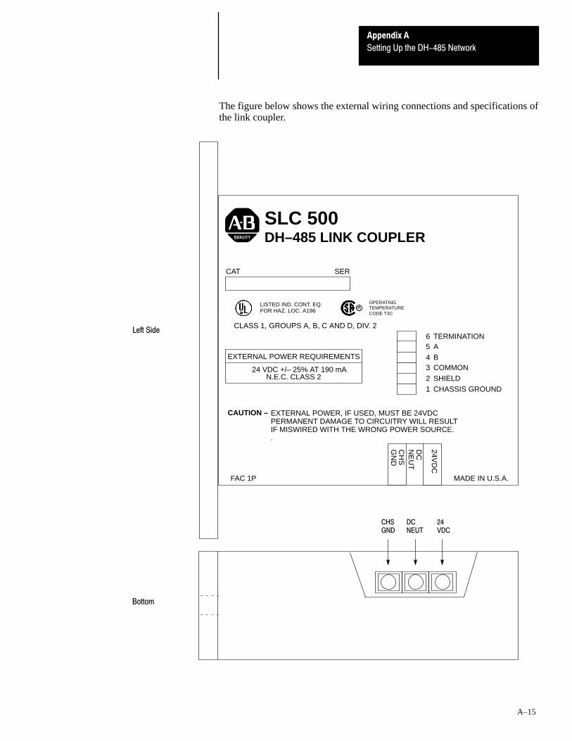
Appendix A
Setting Up the DH-485 Network
A–15
The figure below shows the external wiring connections and specifications ofthe link coupler.
TERMINATIONABCOMMONSHIELDCHASSIS GROUND
654321
SLC 500DH–485 LINK COUPLER
CAT SER
EXTERNAL POWER REQUIREMENTS
24 VDC +/– 25% AT 190 mAN.E.C. CLASS 2
24VD
C
CH
SG
ND
NE
UT
DC
MADE IN U.S.A.
CAUTION – EXTERNAL POWER, IF USED, MUST BE 24VDCPERMANENT DAMAGE TO CIRCUITRY WILL RESULTIF MISWIRED WITH THE WRONG POWER SOURCE..
FAC 1P
LISTED IND. CONT. EQ.FOR HAZ. LOC. A196
OPERATINGTEMPERATURECODE T3C
CLASS 1, GROUPS A, B, C AND D, DIV. 2
CHSGND
DCNEUT
24VDC
Bottom
Left Side
Appendix A
Setting Up the DH-485 Network
A–16
You can connect an unpowered link coupler to the DH–485 network withoutdisrupting network activity. In addition, if an SLC 500 controller powers alink coupler that is connected to the DH–485 network, network activity willnot be disrupted should the SLC 500 controller be removed from the linkcoupler.
Installing and Attaching the Link Couplers
1. Take care when installing the link coupler in an enclosure so that thecable connecting the SLC 500 controller to the link coupler does not hitthe enclosure door.
2. Carefully plug the terminal block into the DH–485 port on the linkcoupler you are putting on the network. Allow enough cable slack toprevent stress on the plug.
3. Provide strain relief for the Belden #9842 cable after it is wired to theterminal block. This guards against breakage of the Belden cable wires.

BAppendix
B–1
The 1771-Remote I/O Network
This appendix provides a brief introduction about the 1771–Remote I/ONetwork. For information on the 1771–Remote I/O Network, see the DirectCommunication Module User Manual, Catalog Number 1747–NM007 andthe Remote I/O Scanner User Manual, Catalog Number 1747–NM005.
The Allen–Bradley 1771–Remote I/O Network enables chassis of I/O,operator interface terminals, push–button panels, blocks of I/O, messagedisplays, drives and much more to be great distances from the host PLCprocessor. The SLC 500 controller (fixed, 5/01, 5/02, or 5/03) can interfaceto this network through the 1747–DCM module for distributed processing.The DCM allows the SLC 500 to look like another device on the network.
Below is an example of the 1771–Remote I/O Network.
PanelViewOperator Terminal
PLC-5/15 orPLC-5/25
Fixed
1771-Remote I/O Network
SLC 5/01 SLC 5/02
1747-DCM 1747-DCM 1747-DCM
With the SLC 5/02 or 5/03 processor, a 1747–SN Remote I/O Scanner can beused as the host of the remote I/O network. With a SLC 5/02 or 5/03 andSN, a PLC is not required on the network.
PanelViewOperator Terminal
SLC 5/02
1771-Remote I/O Network
Block I/O
SLC 5/02
1747-SN
1747-DCM
1771-Remote I/O Network

CAppendix
C–1
RS-232 Communication Interface
This appendix provides an overview of the RS–232 communication interface.This appendix also provides information on the following:
• RS–232 and SCADA applications• RS–232 communication interface overview• SLC 500 devices that support RS–232 communication• wiring connectors for RS–232 communication
RS–232 is a communication interface included under SCADA (SupervisoryControl and Data Acquisition) applications. SCADA is a term that refers tocontrol applications that require communication over long distances. Formore information about the use of Allen–Bradley equipment in SCADAapplications, refer to the Allen–Bradley SCADA Applications Guide,Publication Number ICCG–11.6.
RS–232 is an Electronics Industries Association (EIA) standard that specifiesthe electrical, mechanical, and functional characteristics for serial binarycommunication. It provides you with a variety of system configurationpossibilities that differ from those offered by DH–485.
One of the biggest benefits of RS–232 communication is that it lets youintegrate telephone and radio modems into your control system. Thedistance over which you are able to communicate with certain system devicesis virtually limitless.
The SLC and PLC products detailed in this appendix that communicate overthe RS–232 communication interface also use the DF1 serial communicationprotocol. DF1 protocol delimits messages, controls message flow, detectsand signals errors, and retries after errors are detected.
RS-232 and SCADAApplications
RS-232 CommunicationInterface Overview

Appendix C
RS-232 Communication Interface
C–2
The SLC 500 product line has three other modules, aside from the SLC 5/03processor, that support the RS–232 communication interface. They are theDH–485 Communication Interface (1770–KF3), the BASIC module(1746–BAS), and the DH–485/RS–232C Interface (1747–KE). All three ofthese modules can be used with SLC 500 Fixed Controller.
1770-KF3 Module
The 1770–KF3 module links host computers with the Allen–BradleyDH–485 Data Highway. The host computer communicates with the1770–KF3 over an RS232 link using DF1 protocol. Through the 1770–KF3,the host computer can communicate with the nodes on the DH–485 network.
For more information on the 1770–KF3 module, see the DH–485Communication Interface User Manual, Catalog Number 1770–6.5.18.
1747-KE Module
The 1747–KE is a communication interface module that acts as a bridgebetween DH–485 networks and devices requiring DF1 protocol. You canconfigure the DF1 port on the 1747–KE for RS–232/423, RS–422, orRS–485 devices. Residing in an SLC 500 chassis, the 1747–KE is ideallyused as an interface module, linking remote DH–485 networks via a modemto a central host.
For more information on the 1747–KE module, see the DH–485/RS–232Interface Module User Manual, Catalog Number 1747–NU001.
1746-BAS Module
The 1746–BAS module, which is programmed using the BASIC language,has two configurable serial ports for interfacing to computers, modems,printers, and other RS–232 compatible devices. You can also use it foroff–loading complex math routines from an SLC 500 processor; thisconserves valuable ladder logic memory.
For more information on the 1746–BAS module, see the SLC 500 BASICModule Design and Integration Manual, Catalog Number 1746–ND005.
SLC 500 Devices that SupportRS-232 Communication
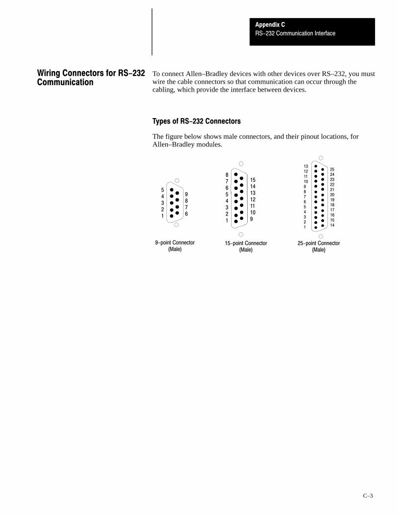
Appendix C
RS-232 Communication Interface
C–3
To connect Allen–Bradley devices with other devices over RS–232, you mustwire the cable connectors so that communication can occur through thecabling, which provide the interface between devices.
Types of RS-232 Connectors
The figure below shows male connectors, and their pinout locations, forAllen–Bradley modules.
9-point Connector(Male)
15-point Connector(Male)
25-point Connector(Male)
252423222120191817161514
13121110987654321
87654321
1514131211109
54321
9876
Wiring Connectors for RS-232Communication

Appendix C
RS-232 Communication Interface
C–4
DTE Pinout
Channel 0, which the 5/03 processor has, is configured as DTE. The pinoutsare the same as the 9–pin AT port.
DTE 9 pinout Signal isEquivalentDTE 15 pinout
EquivalentDTE 25 pinout
1 -DCD Data Carrier Detect Input 8 8
2 -RXD Received Data Input 3 3
3 -TXD Transmitted Data Output 2 2
4 -DTR Data Terminal Ready Output 11 20
5 -COM Common Return (Signal Ground) Shared 7 7
6 -DSR Data Set Ready Input 6 6
7 -RTS Request to Send Output 4 4
8 -CTS Clear to Send Input 5 5
9 -NC No Connection Input 22 RI Ring Indicator
DCE Pinout
Devices such as a modem are DCE. The pinouts on these terminals arewired to interface with DTE.
DCE 9 pinout Signal isEquivalentDCE 25 pinout
1 -DCD Data Carrier Detect Output 8
2 -RXD Received Data Output 3
3 -TXD Transmitted Data Input 2
4 -DTR Data Terminal Ready Input 20
5 -COM Common Return (Signal Ground) Shared 7
6 -DSR Data Set Ready Output 6
7 -RTS Request to Send Input 4
8 -CTS Clear to Send Output 5
9 -RI Ring Indicator Output 22
Important: DCE signal names are viewed from a DTE perspective. Forexample, TXD is a DTE output and also a DCE input.

Appendix C
RS-232 Communication Interface
C–5
Pin Assignments for Wiring Connectors
Use the following pin assignments to wire the connectors of Allen–Bradleycontrol devices with modems and peripheral devices that support RS–232communication. See the table below to find the wiring diagram that youneed.
To Connect thisDevice
To this Device RemarksSee this
Page
IBM ATModem Hardware Handshaking Enabled C-6
IBM ATPeripheral DTE Hardware Handshaking Disabled C-6
1747-KEModem Hardware Handshaking Enabled C-7
1747-KEPeripheral DTE Hardware Handshaking Disabled C-7
1746-BASModem Hardware Handshaking Enabled C-8
1746-BASPeripheral DTE Hardware Handshaking Disabled C-8
1770-KF3 Modem Hardware Handshaking Enabled C-8
2760-RBModem Hardware Handshaking Enabled C-9
2760-RBPeripheral DTE Hardware Handshaking Disabled C-9
1771-KGM (PLC-2)Modem Hardware Handshaking Enabled C-10
1771-KGM (PLC-2)Peripheral DTE Hardware Handshaking Disabled C-10
1775-KA (PLC-3)Modem Hardware Handshaking Enabled C-11
1775-KA (PLC-3)Peripheral DTE Hardware Handshaking Disabled C-11
PLC-5 (channel 0)Modem Hardware Handshaking Enabled C-12
PLC-5 (channel 0)Peripheral DTE Hardware Handshaking Disabled C-12
5130-RM (PLC-5/250)Modem Hardware Handshaking Enabled C-13
5130-RM (PLC-5/250)Peripheral DTE Hardware Handshaking Disabled C-13

Appendix C
RS-232 Communication Interface
C–6
IBM AT to a Modem (Hardware Handshaking Enabled)
DCD
RI
1
2
3
4
5
6
7
8
9
8
3
2
20
7
6
4
5
22
RXD
TXD
DTR
COM
DSR
RTS
CTS
GND 1
1
3
3
4
5
6
7
8
9
8
2
2
20
7
6
4
5
22
DCD
RI
RXD
TXD
DTR
COM
DSR
RTS
CTS
9 Pin25 Pin IBM AT
9 Pin 25 PinModem
➀
(DTE) (DCE)
➀ Connect to the shield of the cable.
IBM AT to a 5/03 Processor, 1770–KF3, 1775–KA, 1773–KA, 5130–RM,or PLC–5 (Hardware Handshaking Disabled) ➀
DCD 1
3
2
4
5
6
7
8
8
2
3
20
7
6
4
5
TXD
RXD
DTR
COM
DSR
RTS
CTS
GND 1
1
3
3
4
5
6
7
8
9
8
2
2
20
7
6
4
5
22
DCD
RI
RXD
TXD
DTR
COM
DSR
RTS
CTS
9 Pin25 Pin IBM AT
9 Pin 25 Pin
(DTE) (DTE)
➁
➁
Peripheral
➁
➁
Device➂
➀ You can also use cable 1747-CP3.➁ Jumpers are only needed if you cannot disable the hardware handshaking on the port.➂ Connect to the shield of the cable.

Appendix C
RS-232 Communication Interface
C–7
1747–KE to a Modem (Hardware Handshaking Enabled)
DSR 6
2
3
4
5
1
7
8
6
3
2
20
7
8
4
5
RXD
TXD
DTR
COM
DCD
RTS
CTS
GND 1
1
3
4
5
6
7
8
9
2
NC
NC
RXD
TXD
DTR
COM
DSR
RTS
CTS
9 Pin 1747–KE
9 Pin 25 Pin➀
(DTE) (DCE)
Modem
9 22RI
➀ Connect to the shield of the cable.
1747–KE to a 5/03 Processor, IBM AT, 1770–KF3, 1775–KA, 1773–KA,5130–RM, or PLC–5 (Hardware Handshaking Disabled) ➀
DCD 1
3
2
4
5
6
7
8
8
2
3
20
7
6
4
5
TXD
RXD
DTR
COM
DSR
RTS
CTS
1
3
4
5
6
7
8
9
2
NC
NC
RXD
TXD
DTR
COM
DSR
RTS
CTS
9 Pin 1747–KE
(DTE) (DTE)
1GND
➁
➁
➁
9 Pin 25 PinPeripheralDevice
➁
➂
➀ You can also use cable 1747-CP3.➁ Jumpers are only needed if you cannot disable the hardware handshaking on the port.➂ Connect to the shield of the cable.

Appendix C
RS-232 Communication Interface
C–8
1746–BAS to a Modem (Hardware Handshaking Enabled)
DSR 6
2
3
4
5
1
7
8
6
3
2
20
7
8
4
5
RXD
TXD
DTR
COM
DCD
RTS
CTS
GND 1
1
3
4
5
6
7
8
9
2
NC
NC
RXD
TXD
DTR
COM
DSR
RTS
CTS
9 Pin 1746–BAS
9 Pin 25 Pin➀
(DTE) (DCE)
Modem
9 22RI
➀ Connect to the shield of the cable.
1746–BAS to a 5/03 Processor, IBM AT, 1770–KF3, 1775–KA, 1773–KA,5130–RM, or PLC–5 (Hardware Handshaking Disabled)➀
NC 1
3
2
4
5
6
7
8
8
2
3
20
7
6
4
5
TXD
RXD
DTR
COM
DSR
RTS
CTS
1
3
4
5
6
7
8
9
2
NC
NC
RXD
TXD
DTR
COM
DSR
RTS
CTS
9 Pin 1746–BAS
(DTE) (DTE)
1GND
➁
➁
➁
9 Pin 25 PinPeripheralDevice
➁
➂
➀ You can also use cable 1747-CP3.➁ Jumpers are only needed if you cannot disable the hardware handshaking on the port.➂ Connect to the shield of the cable.
1770–KF3 to a Modem (Hardware Handshaking Enabled)
DCD 1
2
3
4
5
6
7
8
8
3
2
20
7
6
4
5
RXD
TXD
DTR
COM
DSR
RTS
CTS
GND 1
8
2
20
7
6
4
5
22
3
DCD
NC
RXD
TXD
DTR
COM
DSR
RTS
CTS
25 Pin 1770–KF3
9 Pin 25 Pin➀
(DTE) (DCE)
Modem
9 22RI
➀ Connect to the shield of the cable.

Appendix C
RS-232 Communication Interface
C–9
2760–RB to a Modem (Hardware Handshaking Enabled)
DCD 1
3
2
7
8
6
5
4
8
2
3
4
5
6
7
20
TXD
RXD
RTS
CTS
DSR
COM
DTR
1
3
4
5
6
7
20
2
TXD
RXD
RTS
CTS
DSR
COM
DTR
25 Pin 2760–RB
(DTE) (DCE)
22
GND
9 Pin 25 PinModem
1GND
RI 9
➀
➀
➀ Connect the shield of the cable to the GND pin on one end only. Leave the other end open.
2760–RB to a 5/03 Processor, IBM AT, 1770–KF3, 1775–KA, 1773–KA,5130–RM, or PLC–5 (Hardware Handshaking Disabled) ➀
DCD 1
3
2
7
8
6
5
4
8
2
3
4
5
6
7
20
RXD
TXD
DTR
COM
DSR
RTS
CTS
1
3
4
5
6
7
20
2
TXD
RXD
RTS
CTS
DSR
COM
DTR
25 Pin 2760–RB
(DTE) (DTE)
GND
9 Pin 25 PinPerihpheral
1GND
➁
➁
➁
➁
➂
➂
Device
➀ You can also use cable 1747-CP3.➁ Jumpers are only needed if you cannot disable the hardware handshaking on the port.➂ Connect the shield of the cable to the GND pin on one end only. Leave the other end open.
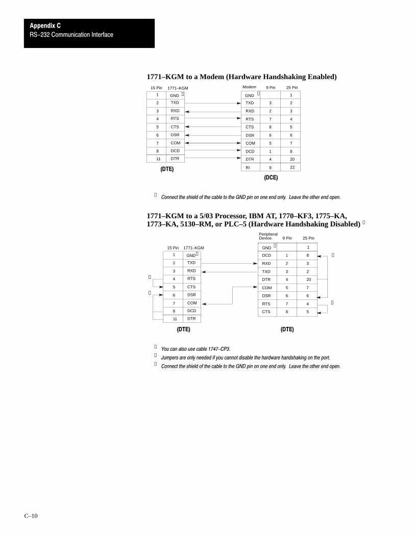
Appendix C
RS-232 Communication Interface
C–10
1771–KGM to a Modem (Hardware Handshaking Enabled)
TXD 3
2
7
8
6
5
1
4
2
3
4
5
6
7
8
20
RXD
RTS
CTS
DSR
COM
DCD
DTR
1
3
4
5
6
7
8
2
TXD
RXD
RTS
CTS
DSR
COM
DCD
15 Pin 1771–KGM
(DTE)
(DCE)
22
GND
9 Pin 25 PinModem
1GND
RI 9
11 DTR
➀➀
➀ Connect the shield of the cable to the GND pin on one end only. Leave the other end open.
1771–KGM to a 5/03 Processor, IBM AT, 1770–KF3, 1775–KA,1773–KA, 5130–RM, or PLC–5 (Hardware Handshaking Disabled) ➀
DCD 1
2
3
4
5
6
7
8
8
3
2
20
7
6
4
5
RXD
TXD
DTR
COM
DSR
RTS
CTS
(DTE) (DTE)
9 Pin 25 PinPeripheral
1GND
➁
➁
➁
➁
➂
➂
1
3
4
5
6
7
8
2
TXD
RXD
RTS
CTS
DSR
COM
DCD
15 Pin
GND
11 DTR
1771–KGM
Device
➀ You can also use cable 1747-CP3.➁ Jumpers are only needed if you cannot disable the hardware handshaking on the port.➂ Connect the shield of the cable to the GND pin on one end only. Leave the other end open.
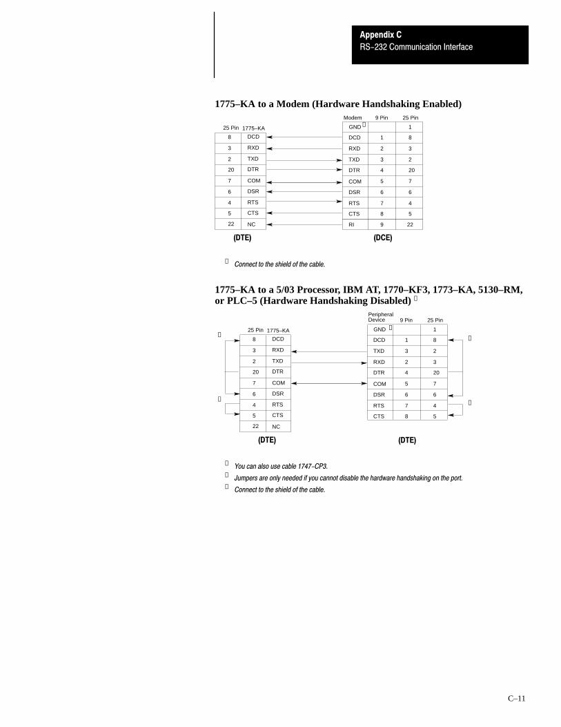
Appendix C
RS-232 Communication Interface
C–11
1775–KA to a Modem (Hardware Handshaking Enabled)
DCD 1
2
3
4
5
6
7
8
8
3
2
20
7
6
4
5
RXD
TXD
DTR
COM
DSR
RTS
CTS
GND 1
8
2
20
7
6
4
5
22
3
DCD
NC
RXD
TXD
DTR
COM
DSR
RTS
CTS
25 Pin 1775–KA
9 Pin 25 Pin➀
(DTE) (DCE)
Modem
9 22RI
➀ Connect to the shield of the cable.
1775–KA to a 5/03 Processor, IBM AT, 1770–KF3, 1773–KA, 5130–RM,or PLC–5 (Hardware Handshaking Disabled) ➀
DCD 1
3
2
4
5
6
7
8
8
2
3
20
7
6
4
5
TXD
RXD
DTR
COM
DSR
RTS
CTS
GND 1
8
2
20
7
6
4
5
22
3
DCD
NC
RXD
TXD
DTR
COM
DSR
RTS
CTS
25 Pin 1775–KA
9 Pin 25 Pin
(DTE) (DTE)
Peripheral
➁
➁
➁
➁
Device
➂
➀ You can also use cable 1747-CP3.➁ Jumpers are only needed if you cannot disable the hardware handshaking on the port.➂ Connect to the shield of the cable.

Appendix C
RS-232 Communication Interface
C–12
PLC–5 (Channel 0) to a Modem (Hardware Handshaking Enabled)
DCD 1
2
3
4
5
6
7
8
8
3
2
20
7
6
4
5
RXD
TXD
DTR
COM
DSR
RTS
CTS
GND 1
8
2
20
7
6
4
5
22
3
DCD
NC
RXD
TXD
DTR
COM
DSR
RTS
CTS
25 Pin PLC–5 (ch. 0)
9 Pin 25 Pin➀
(DTE) (DCE)
Modem
9 22RI
➀ Connect to the shield of the cable.
PLC–5 (Channel 0) to a 5/03 Processor, IBM AT, 1770–KF3, 1773–KA,5130–RM, PLC–5, 1747–KE, or 1746–BAS (Hardware HandshakingDisabled) ➀
DCD 1
3
2
4
5
6
7
8
8
2
3
20
7
6
4
5
TXD
RXD
DTR
COM
DSR
RTS
CTS
GND 1
8
2
20
7
6
4
5
22
3
DCD
NC
RXD
TXD
DTR
COM
DSR
RTS
CTS
9 Pin 25 Pin
(DTE) (DTE)
Peripheral
➁
➁
➁
➁
25 Pin PLC–5 (ch. 0)
Device➂
➀ You can also use cable 1747-CP3.➁ Jumpers are only needed if you cannot disable the hardware handshaking on the port.➂ Connect to the shield of the cable.

Appendix C
RS-232 Communication Interface
C–13
5130–RM to a Modem (Hardware Handshaking Enabled)
DCD 1
2
3
4
5
6
7
8
8
3
2
20
7
6
4
5
RXD
TXD
DTR
COM
DSR
RTS
CTS
GND 1
8
2
20
7
6
4
5
22
3
DCD
NC
RXD
TXD
DTR
COM
DSR
RTS
CTS
25 Pin 5130–RM
9 Pin 25 Pin➀
(DTE) (DCE)
Modem
9 22RI
➀ Connect to the shield of the cable.
5130–RM to a 5/03 Processor, IBM AT, 1770–KF3, 1773–KA, 5130–RM,PLC–5, 1747–KE, or 1746–BAS (Hardware Handshaking Disabled) ➀
DCD 1
3
2
4
5
6
7
8
8
2
3
20
7
6
4
5
TXD
RXD
DTR
COM
DSR
RTS
CTS
GND 1
8
2
20
7
6
4
5
22
3
DCD
NC
RXD
TXD
DTR
COM
DSR
RTS
CTS
9 Pin 25 Pin
(DTE) (DTE)
Peripheral
➁
➁
➁
➁
25 Pin 5130–RM
Device➂
➀ You can also use cable 1747-CP3.➁ Jumpers are only needed if you cannot disable the hardware handshaking on the port.➂ Connect to the shield of the cable.


DAppendix
D–1
Calculating Heat Dissipation for the SLC 500Control System
This appendix will assist you in calculating the heat dissipation of your SLC500 control system. It consists of the following:
• definition of key terms• table and graphs• example heat dissipation calculation• heat dissipation worksheet (page D–5)
To select an enclosure for your SLC 500 control system, refer to chapter 1.
The following terms are used throughout this appendix. Familiarize yourselfwith them before proceeding further into the appendix.
Watts per point — maximum heat dissipation that can occur in each fieldwiring point when energized.
Minimum watts — amount of heat dissipation that can occur when there isno field power present.
Maximum watts — maximum amount of heat that the module generateswith field power present.
There are two ways that you can calculate heat dissipation.
Calculated Watts — if you want to determine the amount of heat generatedby the points energized on your module, use the formula below forcalculating the heat dissipation of each module. Then use these values forcalculating the heat dissipation of your control system, which is done usingthe worksheet.
(number of points energized x watts per point) + minimum watts = heat dissipation of module or controller
Maximum Watts — maximum amount of heat that the module generateswith field power present. Use maximum watts especially if you are not surehow many points on a module will be energized at any time.
Once you have determined which way you will calculate the heat dissipationof your modules, see the Example Worksheet for Calculating HeatDissipation on page D–4. This worksheet shows you how to calculate theheat dissipation for the example SLC control system also on page D–4.Once you feel comfortable with the layout of the worksheet, go to theworksheet on page D–5 and fill it out for your control system.
Definition of Key Terms
Module Heat Dissipation:Calculated Watts vs. MaximumWatts

Control System
Appendix D
Calculating Heat Dissipation for the SLC 500
D–2
Use the table below to calculate the power supply loading for each chassisthat you have (step 1 of the worksheet).
HardwareComponent
CatalogNumbers
Watts per PointMinimum
WattsMaximum
Watts
1747-L20A 0.27 10.5 15.0
1747-L30A 0.27 12.7 19.2
1747-L40A 0.27 14.3 23.0
1747-L20B 0.27 9.9 17.0
1747-L30B 0.27 11.6 22.0
1747-L40B 0.27 13.0 27.0
1747-L20C 0.20 17.4 21.0
1747-L30C 0.20 18.7 24.0
1747-L40C 0.20 19.9 27.0
1747-L20D 0.20 12.4 19.0
1747-L30D 0.20 13.9 23.0
Fixed 1747-L20E 0.20 12.6 18.0FixedControllers 1747-L40E 0.20 16.0 27.0
1747-L20F 0.20 5.0 9.0
1747-L40F 0.20 7.4 15.0
1747-L20G 0.20 4.4 10.0
1747-L20L 0.20 12.1 18.0
1747-L30L 0.20 14.0 23.0
1747-L40L 0.20 16.0 27.0
1747-L20N 0.20 4.4 10.0
1747-L20P 0.35 8.8 17.0
1747-L30P 0.35 10.5 23.0
1747-L40P 0.35 11.6 28.0
1747-L20R 0.35 10.5 16.0
1746-IA4 0.27 0.175 1.30
1746-IA8 0.27 0.250 2.40
1746-IA16 0.27 0.425 4.80
1746-IM4 0.35 0.175 1.60
1746-IM8 0.35 0.250 3.10
1746-IM16 0.35 0.425 6.00
Input 1746-IB8 0.20 0.250 1.90InputModules 1746-IB16 0.20 0.425 3.60
1746-IB32 0.20 0.530 6.90
1746-IV8 0.20 0.250 1.90
1746-IV16 0.20 0.425 3.60
1746-IV32 0.20 0.530 6.90
1746-IG16 0.020 0.700 1.00
1746-IN16 0.35 0.425 6.00
1746-OA8 1.00 0.925 9.00
1746-OA16 0.462 1.85 9.30
Output 1746-OB8 0.775 0.675 6.90OutputModules 1746-OB16 0.338 1.40 7.60
1746-OB32 0.078 2.26 4.80
1746-OV8 0.775 0.675 6.90
Use this Table to Calculate thePower Supply Loading

Control System
Appendix D
Calculating Heat Dissipation for the SLC 500
D–3
HardwareComponent
CatalogNumbers
Watts per PointMinimum
WattsMaximum
Watts
1746-OV16 0.388 1.40 7.60
1746-OV32 0.078 2.26 4.80
O t t1746-OW4 0.133 1.31 1.90
OutputModules
1746-OW8 0.138 2.59 3.70Modules
1746-OW16 0.033 5.17 5.70
1746-OX8 0.825 2.59 8.60
1746-OG16 0.033 0.900 1.50
Input &
1746-IO40.27 per input pt.0.133 per output pt.
0.75 1.60
Input &OutputModules
1746-IO80.27 per input pt.0.133 per output pt.
1.38 3.00Modules
1746-IO120.27 per input pt.0.133 per output pt.
2.13 4.60
1746-NI4 NA 2.17 2.2
1746-NIO4I NA 3.76 3.8
1746-NIO4V NA 3.04 3.1
S i lt1746-NO4I NA 4.96 5.0
SpecialtyModules
1746-NO4V NA 3.78 3.8Modules
1746-BAS NA 3.75 3.8
1747-DCM NA 1.8 1.8
1747-DSN NA 4.5 4.5
1747-KE NA 3.75 3.8
1747-AIC NA 2.0 2.0
Peripheral1747-DTAM NA 2.5 2.5
PeripheralDevices 1747-PT1
Series A & BNA 2.5 2.5
1747-PIC NA 2.0 2.0
NA Not Applicable
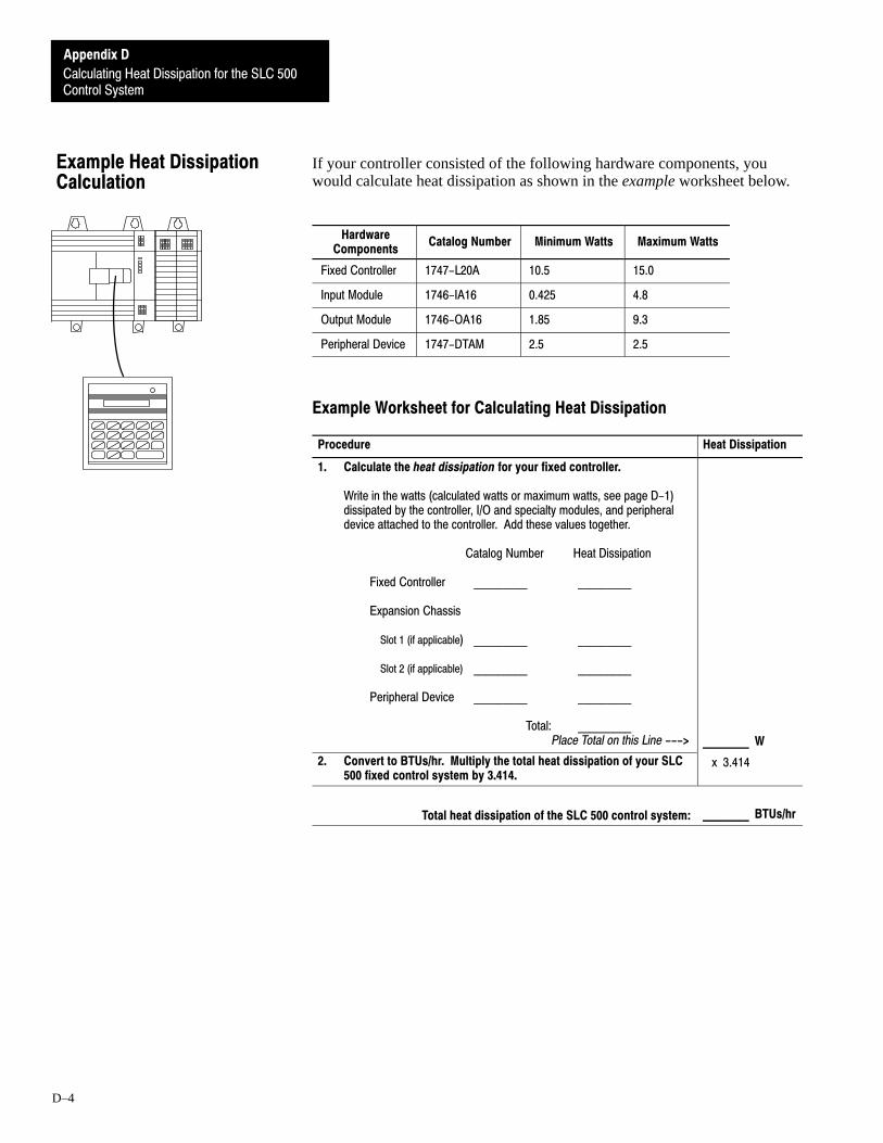
Control System
Appendix D
Calculating Heat Dissipation for the SLC 500
D–4
If your controller consisted of the following hardware components, youwould calculate heat dissipation as shown in the example worksheet below.
HardwareComponents
Catalog Number Minimum Watts Maximum Watts
Fixed Controller 1747-L20A 10.5 15.0
Input Module 1746-IA16 0.425 4.8
Output Module 1746-OA16 1.85 9.3
Peripheral Device 1747-DTAM 2.5 2.5
Example Worksheet for Calculating Heat Dissipation
Procedure Heat Dissipation
1. Calculate the heat dissipation for your fixed controller.
Write in the watts (calculated watts or maximum watts, see page D-1) dissipated by the controller, I/O and specialty modules, and peripheral device attached to the controller. Add these values together.
Catalog Number Heat Dissipation
Fixed Controller _________ _________
Expansion Chassis
Slot 1 (if applicable) _________ _________
Slot 2 (if applicable) _________ _________
Peripheral Device _________ _________
Total: _________Place Total on this Line ---> _______ W
2. Convert to BTUs/hr. Multiply the total heat dissipation of your SLC 500 fixed control system by 3.414.
x 3.414
Total heat dissipation of the SLC 500 control system: _______ BTUs/hr
Example Heat DissipationCalculation

Control System
Appendix D
Calculating Heat Dissipation for the SLC 500
D–5
Use this worksheet to calculate the heat dissipation for your fixed controller.
Procedure Heat Dissipation
1. Calculate the heat dissipation for your fixed controller.
Write in the watts (calculated watts or maximum watts, see page D-1) dissipated by the controller, I/O and specialty modules, and peripheral device attached to the controller. Add these values together.
Catalog Number Heat Dissipation
Fixed Controller _________ _________
Expansion Chassis
Slot 1 (if applicable) _________ _________
Slot 2 (if applicable) _________ _________
Peripheral Device _________ _________
Total: _________Place Total on this Line ---> ___________ W
2. Convert to BTUs/hr. Multiply the total heat dissipation of your SLC 500 fixed control system by 3.414.
x 3.414
Total heat dissipation of the SLC 500 control system: __________ BTUs/hr
Worksheet for CalculatingHeat Dissipation


EAppendix
E–1
Wiring and Circuit Diagrams and VoltageRanges for Your Fixed Controller
This appendix covers the following for your fixed controller.
• wiring diagrams• circuit diagrams• voltage ranges
The following table provides an explanation of the symbols used in thewiring diagrams. The symbols do not indicate the only type of I/O devicesthat can be connected, but rather a “typical” device. As long as your I/Odevice meets the I/O circuit specifications, it should be compatible.
CR Control relay
Solenoid
Mechanicalswitch
Solid-stateswitch
This SymbolRepresents TypicalOutput Device
This SymbolRepresents TypicalInput Device
The connections illustrated in the wiring diagrams are shown for examplepurposes only.
• You can connect I/O devices in any order to the I/O circuits. If you arenot going to load all of your circuits, space the connections evenly apartto help in heat dissipation.
• All the input circuits on any one fixed controller are the same with oneexception: input 0 is unique for all fixed controllers which have 24 VDCinput circuits. In this case, input 0 can be used as a high–speed counter.The diagrams in this appendix show the differences in operatingcharacteristics.
• All the output circuits on any one fixed controller are the same.
In the wiring diagrams for the fixed controller with 24 VDC input circuitsand 120/240 VAC line power, the User Power Source (terminals next toPower Supply terminals — “PWR OUT 24 VDC” and “PWR OUT COM”)is shown to power some input devices. This is optional. The User PowerSource can provide up to 200mA at 24 VDC for input devices.
Wiring Symbols

for Your Fixed Controller
Appendix E
Wiring and Circuit Diagrams and Voltage Ranges
E–2
Use the table below to locate the appropriate wiring and circuit diagrams andvoltage ranges.
CatalogNumbers
Description➀ WiringDiagram
InputCircuit
Diagram
On/OffState
Voltage
OutputCircuit
Diagram
OperatingVoltageRange
1747-L20A(12) 120 VAC Inputs and (8)Relay Outputs
E-4 E-5 E-5 E-5 E-5
1747-L20B(12) 120 VAC Inputs and (8)Triac Outputs
E-6 E-7 E-7 E-7 E-7
1747-L20C(12) 24 VDC Sinking Inputs,High-Speed Counter Inputand (8) Relay Outputs
E-8 E-9 E-9 E-10 E-10
1747-L20D(12) 24 VDC Sinking Inputs,High-Speed Counter Inputand (8) Triac Outputs
E-11 E-12 E-12 E-13 E-13
1747-L20E
(12) 24 VDC Sinking Inputs,High-Speed Counter Inputand (8) Transistor SourcingOutputs
E-14 E-15 E-15 E-16 E-16
1747-L20F(12) 24 VDC Sinking Inputs,High-Speed Counter Inputand (8) Relay Outputs
E-17 E-18 E-18 E-19 E-19
1747-L20G
(12) 24 VDC Sinking Inputs,High-Speed Counter Inputand (8) Transistor SourcingOutputs
E-20 E-21 E-21 E-22 E-22
1747-L20L
(12) 24 VDC Sourcing Inputs,High-Speed Counter Inputand (8) Transistor SinkingOutputs
E-23 E-24 E-24 E-25 E-25
1747-L20N
(12) 24 VDC Sourcing Inputs,High-Speed Counter Inputand (8) Transistor SinkingOutputs
E-26 E-27 E-27 E-28 E-28
1747-L20P(12) 240 VAC Inputs and (8)Triac Outputs
E-29 E-30 E-30 E-30 E-30
1747-L20R(12) 240 VAC Inputs and (8)Relay Outputs
E-31 E-32 E-32 E-32 E-32
1747-L30A(18) 120 VAC Inputs and (12)Relay Outputs
E-33 E-34 E-34 E-34 E-34
1747-L30B(18) 120 VAC Inputs and (12)Triac Outputs
E-35 E-36 E-36 E-36 E-36
1747-L30C(18) 24 VDC Sinking Inputs,High-Speed Counter Inputand (12) Relay Outputs
E-37 E-38 E-38 E-39 E-39
1747-L30D(18) 24 VDC Sinking Inputs,High-Speed Counter Inputand (12) Triac Outputs
E-40 E-41 E-41 E-42 E-42
1747-L30L
(18) 24 VDC Sourcing Inputs,High-Speed Counter Inputand (12) Transistor SinkingOutputs
E-43 E-44 E-44 E-45 E-45
1747-L30P(18) 240 VAC Inputs and (12)Triac Outputs
E-46 E-47 E-47 E-47 E-47
1747-L40A(24) 120 VAC Inputs and (16)Relay Outputs
E-48 E-49 E-49 E-49 E-49
Wiring and Circuit Diagramsand Voltage Range Locations

for Your Fixed Controller
Appendix E
Wiring and Circuit Diagrams and Voltage Ranges
E–3
CatalogNumbers
OperatingVoltageRange
OutputCircuit
Diagram
On/OffState
Voltage
InputCircuit
Diagram
WiringDiagram
Description➀
1747-L40B(24) 120 VAC Inputs and (16)Triac Outputs
E-50 E-51 E-51 E-51 E-51
1747-L40C(24) 24 VDC Sinking Inputs,High-Speed Counter Inputand (16) Relay Outputs
E-52 E-53 E-53 E-54 E-54
1747-L40E
(24) 24 VDC Sinking Inputs,High-Speed Counter Inputand (16) Transistor SourcingOutputs
E-55 E-56 E-56 E-57 E-57
1747-L40F(24) 24 VDC Sinking Inputs,High-Speed Counter Inputand (16) Relay Outputs
E-58 E-59 E-59 E-60 E-60
1747-L40L
(24) 24 VDC Sourcing Inputs,High-Speed Counter Inputand (16) Transistor SinkingOutputs
E-61 E-62 E-62 E-63 E-63
1747-L40P(24) 240 VAC Inputs and (16)Triac Outputs
E-64 E-65 E-65 E-65 E-65
➀ Refer to page 1-5 for line power specifications.
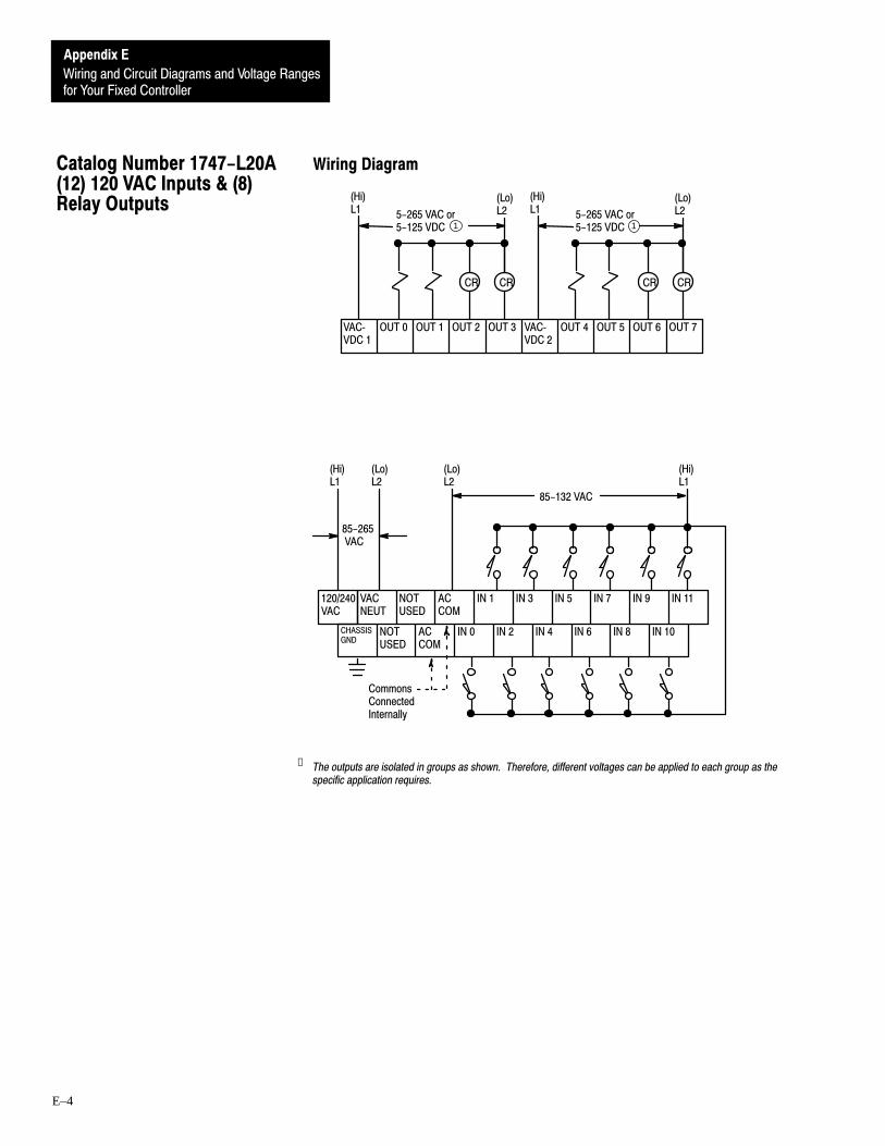
for Your Fixed Controller
Appendix E
Wiring and Circuit Diagrams and Voltage Ranges
E–4
Wiring Diagram
OUT 2 OUT 3 VACVDC 2
OUT 4 OUT 5 OUT 6 OUT 7VACVDC 1
1 15-265 VAC or5-125 VDC
OUT 1
CR CR
OUT 0
(Lo)L2
(Hi)L1
(Hi)L1
CR CR
(Lo)L2
VACNEUT
NOTUSED
ACCOM
IN 1 IN 3 IN 5 IN 7 IN 9 IN 11
CHASSISGND
NOTUSED
ACCOM
IN 0 IN 2 IN 4 IN 6 IN 8 IN 10
120/240VAC
85-132 VAC
(Lo)L2
(Hi)L1
(Lo)L2
(Hi)L1
85-265 VAC
CommonsConnectedInternally
5-265 VAC or5-125 VDC
➀ The outputs are isolated in groups as shown. Therefore, different voltages can be applied to each group as thespecific application requires.
Catalog Number 1747-L20A(12) 120 VAC Inputs & (8)Relay Outputs

for Your Fixed Controller
Appendix E
Wiring and Circuit Diagrams and Voltage Ranges
E–5
Input Circuit Diagram
2 7 0
2 6 1
1 8 7 0
I N
I N
2 7 0 1 8 7 0
2 6 1
0.3µF
0.3µF
1µF
1µF
AC COM
On/Off State Voltage Ranges
ÉÉÉÉÉÉÉÉÉÉÉÉÉÉÉÉÉÉÉÉÉÉÉÉ
On-state
0 VAC 30 VAC 132 VAC
Input State Not Guaranteed
85 VAC
Off-state
Output Circuit Diagram
VAC/VDC
OUT
OUT
Operating Voltage Range
ÉÉÉÉ
Recommended Operating Range
265 VAC
Operation NotGuaranteed
125 VDC0 V 5 VDC0 V 5 VAC
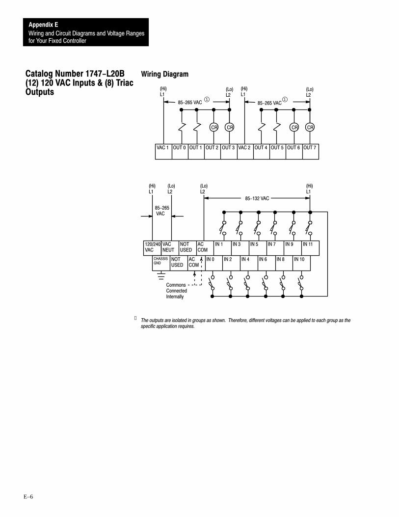
for Your Fixed Controller
Appendix E
Wiring and Circuit Diagrams and Voltage Ranges
E–6
Wiring Diagram
OUT 2 OUT 3 VAC 2 OUT 4 OUT 5 OUT 6 OUT 7VAC 1
85-265 VAC
OUT 1
CR CR
OUT 0
(Lo)L2
(Hi)L1
(Hi)L1
CR CR
(Lo)L2
VACNEUT
NOTUSED
ACCOM
IN 1 IN 3 IN 5 IN 7 IN 9 IN 11
CHASSISGND
NOTUSED
ACCOM
IN 0 IN 2 IN 4 IN 6 IN 8 IN 10
120/240VAC
(Lo)L2
(Hi)L1
(Lo)L2
(Hi)L1
CommonsConnectedInternally
85-265 VAC
85-132 VAC
85-265 VAC
1 1
➀ The outputs are isolated in groups as shown. Therefore, different voltages can be applied to each group as thespecific application requires.
Catalog Number 1747-L20B(12) 120 VAC Inputs & (8) TriacOutputs

for Your Fixed Controller
Appendix E
Wiring and Circuit Diagrams and Voltage Ranges
E–7
Input Circuit Diagram
2 7 0
2 6 1
1 8 7 0
I N
I N
2 7 0 1 8 7 0
2 6 1
0.3µF
0.3µF
1µF
1µF
AC COM
On/Off State Voltage Ranges
ÉÉÉÉÉÉÉÉÉÉÉÉÉÉÉÉÉÉÉÉÉÉÉÉ
On-state
0 VAC 30 VAC 132 VAC
Input State Not Guaranteed
85 VAC
Off-state
Output Circuit Diagram
L1
OUT
OUT
Operating Voltage Range
ÉÉÉÉÉÉÉÉÉÉÉÉÉÉÉÉÉÉ
Recommended Operating Range
0 VAC 265 VAC
Operation Not Guaranteed
85 VAC
Important: If you measure the voltage at an output terminal that is not connected to a load or is connected to a high-impedanceload, you may measure as much as 100 VAC even though the output is off.

for Your Fixed Controller
Appendix E
Wiring and Circuit Diagrams and Voltage Ranges
E–8
Wiring Diagram
PWR OUT+24VDC
PWR OUTCOM
OUT 2 OUT 3 VACVDC 2
OUT 4 OUT 5 OUT 6 OUT 7VACVDC 1
1 15-265 VAC5-125 VDC
OUT 1
CR CR
OUT 0
(Lo)L2
(Hi)L1
(Hi)L1
CR CR
(Lo)L2
VACNEUT
DCCOM
IN 1 IN 3 IN 5 IN 7 IN 9 IN 11
CHASSISGND
DCCOM
IN 0HSC
IN 2 IN 4 IN 6 IN 8 IN 10
120/240VAC
10-30 VDC
CommonsConnectedInternally
(Lo)L2
(Hi)L1
85-265VAC
+ DC- DC
2
2
5-265 VAC5-125 VDC
Sourcing Device
➀ The outputs are isolated in groups as shown. Therefore, different voltages can be applied to each group asthe specific application requires.
➁ 24 VDC, 200mA user power is available for sensors.
Catalog Number 1747-L20C(12) 24 VDC Sinking Inputs,High-Speed Counter Input &(8) Relay Outputs

for Your Fixed Controller
Appendix E
Wiring and Circuit Diagrams and Voltage Ranges
E–9
Input Circuit Diagram
3 9 0
COM
1 . 5 K 1 . 5 K
5 6 0
0.01µF
0.1µF
5 6 0 5 6 0INPUT 0
OTHERINPUTS
(HSC)
On/Off State Voltage Ranges – Input 0 (HSC)
On-stateOff-state
0 VDC 4 VDC 30 VDC10 VDC
ÉÉÉÉÉÉÉÉÉÉ
Input State NotGuaranteed
On/Off State Voltage Ranges – All Other Inputs
On-stateOff-state
0 VDC 5 VDC 30 VDC10 VDC
ÉÉÉÉÉÉÉÉÉÉInput State Not
Guaranteed

for Your Fixed Controller
Appendix E
Wiring and Circuit Diagrams and Voltage Ranges
E–10
Output Circuit Diagram
VAC/VDC
OUT
OUT
Operating Voltage Range
ÉÉÉÉ Recommended Operating Range
265 VAC
Operation NotGuaranteed
125 VDC0 V 5 VDC0 V 5 VAC

for Your Fixed Controller
Appendix E
Wiring and Circuit Diagrams and Voltage Ranges
E–11
Wiring Diagram
OUT 2 OUT 3 VAC 2 OUT 4 OUT 5 OUT 6 OUT 7VAC 1 OUT 1
CR CR
OUT 0
(Lo)L2
(Hi)L1
(Hi)L1
CR CR
(Lo)L2
185-265 VAC 85-265 VAC
1
PWR OUT+24VDC
PWR OUTCOM
VACNEUT
DCCOM
IN 1 IN 3 IN 5 IN 7 IN 9 IN 11
CHASSISGND
DCCOM
IN 0HSC
IN 2 IN 4 IN 6 IN 8 IN 10
120/240VAC
10-30 VDC
CommonsConnectedInternally
(Lo)L2
(Hi)L1
85-265VAC
+ DC- DC
2
2
Sourcing Device
➀ The outputs are isolated in groups as shown. Therefore, different voltages can be applied to each group asthe specific application requires.
➁ 24 VDC, 200mA user power is available for sensors.
Catalog Number 1747-L20D(12) 24 VDC Sinking Inputs,High-Speed Counter Input &(8) Triac Outputs

for Your Fixed Controller
Appendix E
Wiring and Circuit Diagrams and Voltage Ranges
E–12
Input Circuit Diagram
3 9 0
COM
1 . 5 K 1 . 5 K
5 6 0
0.01µF
0.1µF
5 6 0 5 6 0INPUT 0
OTHERINPUTS
(HSC)
On/Off State Voltage Ranges – Input 0 (HSC)
On-stateOff-state
0 VDC 4 VDC 30 VDC10 VDC
ÉÉÉÉÉÉÉÉÉÉÉÉ
Input State NotGuaranteed
On/Off State Voltage Ranges – All Other Inputs
On-stateOff-state
0 VDC 5 VDC 30 VDC10 VDC
ÉÉÉÉÉÉÉÉÉÉInput State Not
Guaranteed

for Your Fixed Controller
Appendix E
Wiring and Circuit Diagrams and Voltage Ranges
E–13
Output Circuit Diagram
L1
OUT
OUT
Operating Voltage Range
ÉÉÉÉÉÉÉÉÉÉÉÉÉÉÉÉÉÉ
Recommended Operating Range
0 VAC 265 VAC
Operation Not Guaranteed
85 VAC
Important: If you measure the voltage at an output terminal that is not connected to a load or is connected to a high-impedanceload, you may measure as much as 100 VAC even though the output is off.

for Your Fixed Controller
Appendix E
Wiring and Circuit Diagrams and Voltage Ranges
E–14
Wiring Diagram
OUT 2 OUT 3 OUT 4 OUT 5 OUT 6 OUT 7 DCCOM
VDC OUT 1
10-50 VDC
CR
OUT 0
+ DC - DC
CR CR CR
PWR OUT+24VDC
PWR OUTCOM
VACNEUT
DCCOM
IN 1 IN 3 IN 5 IN 7 IN 9 IN 11
CHASSISGND
DCCOM
IN 0HSC
IN 2 IN 4 IN 6 IN 8 IN 10
120/240VAC
10-30 VDC
CommonsConnectedInternally
(Lo)L2
(Hi)L1
85-265VAC
+ DC- DC
1
1
Sourcing Device
➀ 24 VDC, 200mA user power is available for sensors.
Catalog Number 1747-L20E(12) 24 VDC Sinking Inputs,High-Speed Counter Input &(8) Transistor SourcingOutputs

for Your Fixed Controller
Appendix E
Wiring and Circuit Diagrams and Voltage Ranges
E–15
Input Circuit Diagram
3 9 0
COM
1 . 5 K 1 . 5 K
5 6 0
0.01µF
0.1µF
5 6 0 5 6 0IN
INOTHERINPUTS
0 HSC
On/Off State Voltage Ranges – Input 0 (HSC)
On-stateOff-state
0 VDC 4 VDC 30 VDC10 VDC
ÉÉÉÉÉÉÉÉÉÉ
Input State NotGuaranteed
On/Off State Voltage Ranges – All Other Inputs
On-stateOff-state
0 VDC 5 VDC 30 VDC10 VDC
ÉÉÉÉÉÉÉÉÉÉInput State Not
Guaranteed
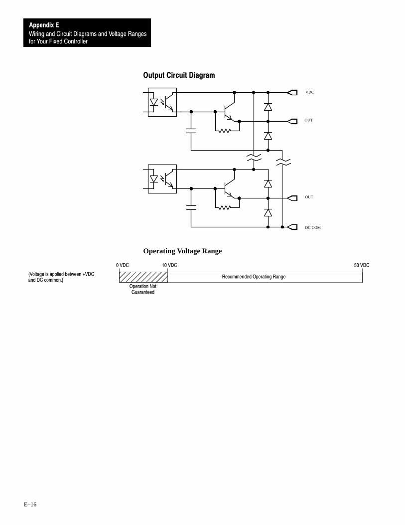
for Your Fixed Controller
Appendix E
Wiring and Circuit Diagrams and Voltage Ranges
E–16
Output Circuit Diagram
VDC
OUT
OUT
DC COM
Operating Voltage Range
ÉÉÉÉÉÉÉÉÉÉÉÉ
Recommended Operating Range
0 VDC 50 VDC10 VDC
Operation NotGuaranteed
(Voltage is applied between +VDCand DC common.)

for Your Fixed Controller
Appendix E
Wiring and Circuit Diagrams and Voltage Ranges
E–17
Wiring Diagram
OUT 2 OUT 3 VACVDC 2
OUT 4 OUT 5 OUT 6 OUT 7VACVDC 1
1 1
OUT 1
CR CR
OUT 0
(Lo)L2
(Hi)L1
(Hi)L1
CR CR
(Lo)L2
VDCNEUT
IN 1 IN 3 IN 5 IN 7 IN 9 IN 11
CHASSISGND
DCCOM
IN 0HSC
IN 2 IN 4 IN 6 IN 8 IN 10
+ 24VDC
DCCOM
NOTUSED
-+
24 VDC
CommonsConnectedInternally
- DC + DC
NOTUSED
10-30 VDC
Sourcing Device
+10%
5-265 VAC or5-125 VDC
5-265 VAC or5-125 VDC
➀ The outputs are isolated in groups as shown. Therefore, different voltages can be applied to each group asthe specific application requires.
Catalog Number 1747-L20F(12) 24 VDC Sinking Inputs,High-Speed Counter Input &(8) Relay Outputs

for Your Fixed Controller
Appendix E
Wiring and Circuit Diagrams and Voltage Ranges
E–18
Input Circuit Diagram
3 9 0
COM
1 . 5 K 1 . 5 K
5 6 0
0.01µF
0.1µF
5 6 0 5 6 0INPUT 0
OTHERINPUTS
(HSC)
On/Off State Voltage Ranges – Input 0 (HSC)
On-stateOff-state
0 VDC 4 VDC 30 VDC10 VDC
ÉÉÉÉÉÉÉÉÉÉÉÉ
Input State NotGuaranteed
On/Off State Voltage Ranges – All Other Inputs
On-stateOff-state
0 VDC 5 VDC 30 VDC10 VDC
ÉÉÉÉÉÉÉÉÉÉInput State Not
Guaranteed

for Your Fixed Controller
Appendix E
Wiring and Circuit Diagrams and Voltage Ranges
E–19
Output Circuit Diagram
VAC/VDC
OUT
OUT
Operating Voltage Range
ÉÉÉÉ
Recommended Operating Range
265 VAC
Operation NotGuaranteed
125 VDC0 V 5 VDC0 V 5 VAC

for Your Fixed Controller
Appendix E
Wiring and Circuit Diagrams and Voltage Ranges
E–20
Wiring Diagram
OUT 2 OUT 3 OUT 4 OUT 5 OUT 6 OUT 7 DCCOM
VDC OUT 1
10-50 VDC
CR
OUT 0
+ DC - DC
CR CR CR
VDCNEUT
IN 1 IN 3 IN 5 IN 7 IN 9 IN 11
CHASSISGND
DCCOM
IN 0HSC
IN 2 IN 4 IN 6 IN 8 IN 10
+ 24VDC
DCCOM
NOTUSED
-+
24 VDC
CommonsConnectedInternally
- DC + DC
NOTUSED
10-30 VDC
Sourcing Device
+10%
Catalog Number 1747-L20G(12) 24 VDC Sinking Inputs,High-Speed Counter Input &(8) Transistor SourcingOutputs

for Your Fixed Controller
Appendix E
Wiring and Circuit Diagrams and Voltage Ranges
E–21
Input Circuit Diagram
3 9 0
COM
1 . 5 K 1 . 5 K
5 6 0
0.01µF
0.1µF
5 6 0 5 6 0INPUT 0
OTHERINPUTS
(HSC)
On/Off State Voltage Ranges – Input 0 (HSC)
On-stateOff-state
0 VDC 4 VDC 30 VDC10 VDC
ÉÉÉÉÉÉÉÉÉÉ
Input State NotGuaranteed
On/Off State Voltage Ranges – All Other Inputs
On-stateOff-state
0 VDC 5 VDC 30 VDC10 VDC
ÉÉÉÉÉÉÉÉÉÉInput State Not
Guaranteed

for Your Fixed Controller
Appendix E
Wiring and Circuit Diagrams and Voltage Ranges
E–22
Output Circuit Diagram
VDC
OUT
OUT
DC COM
Operating Voltage Range
ÉÉÉÉÉÉÉÉÉÉÉÉ
Recommended Operating Range
0 VDC 50 VDC10 VDC
Operation NotGuaranteed
(Voltage is applied between +VDCand DC common.)

for Your Fixed Controller
Appendix E
Wiring and Circuit Diagrams and Voltage Ranges
E–23
Wiring Diagram
10-30 VDC
VDCConnectedInternally
PWR OUT+24 VDC
PWR OUTCOM
OUT 2 OUT 3 OUT 4 OUT 5 OUT 6 OUT 7 DCCOM
VDC OUT 1
CR
OUT 0
+ DC - DC
CR CR CR
VACNEUT
VDC IN 1 IN 3 IN 5 IN 7 IN 9 IN 11
CHASSISGND
VDC IN 0HSC
IN 2 IN 4 IN 6 IN 8 IN 10
120/240VAC
(Lo)L2
(Hi)L1
+ DC - DC
Sinking Device
1
1
OUT 2 OUT 3 OUT 4 OUT 5 OUT 6 OUT 7 DCCOM
VDC OUT 1OUT 0
+ DC - DC
10-50 VDC
85-265 VAC
➀ 24 VDC, 200mA user power is available for sensors.
Catalog Number 1747-L20L(12) 24 VDC Sourcing Inputs,High-Speed Counter Input &(8) Transistor Sinking Outputs

for Your Fixed Controller
Appendix E
Wiring and Circuit Diagrams and Voltage Ranges
E–24
Input Circuit Diagram
3 9 0
VDC
1 . 5 K 1 . 5 K
5 6 00.1µF
INPUT 0(HSC)
OTHERINPUTS
5 6 0 5 6 0
0.01µF
On/Off State Voltage Ranges – Input 0 (HSC)
On-stateOff-state
0 VDC 4 VDC 30 VDC10 VDC
ÉÉÉÉÉÉÉÉÉÉÉÉ
Input State NotGuaranteed
On/Off State Voltage Ranges – All Other Inputs
On-stateOff-state
0 VDC 5 VDC 30 VDC10 VDC
ÉÉÉÉÉÉÉÉÉÉInput State Not
Guaranteed

for Your Fixed Controller
Appendix E
Wiring and Circuit Diagrams and Voltage Ranges
E–25
Output Circuit Diagram
VDC
OUT
DC COM
OUT
Operating Voltage Range
ÉÉÉÉÉÉÉÉÉÉÉÉ
Recommended Operating Range
0 VDC 50 VDC10 VDC
Operation NotGuaranteed
(Voltage is applied between +VDC and DC common.)
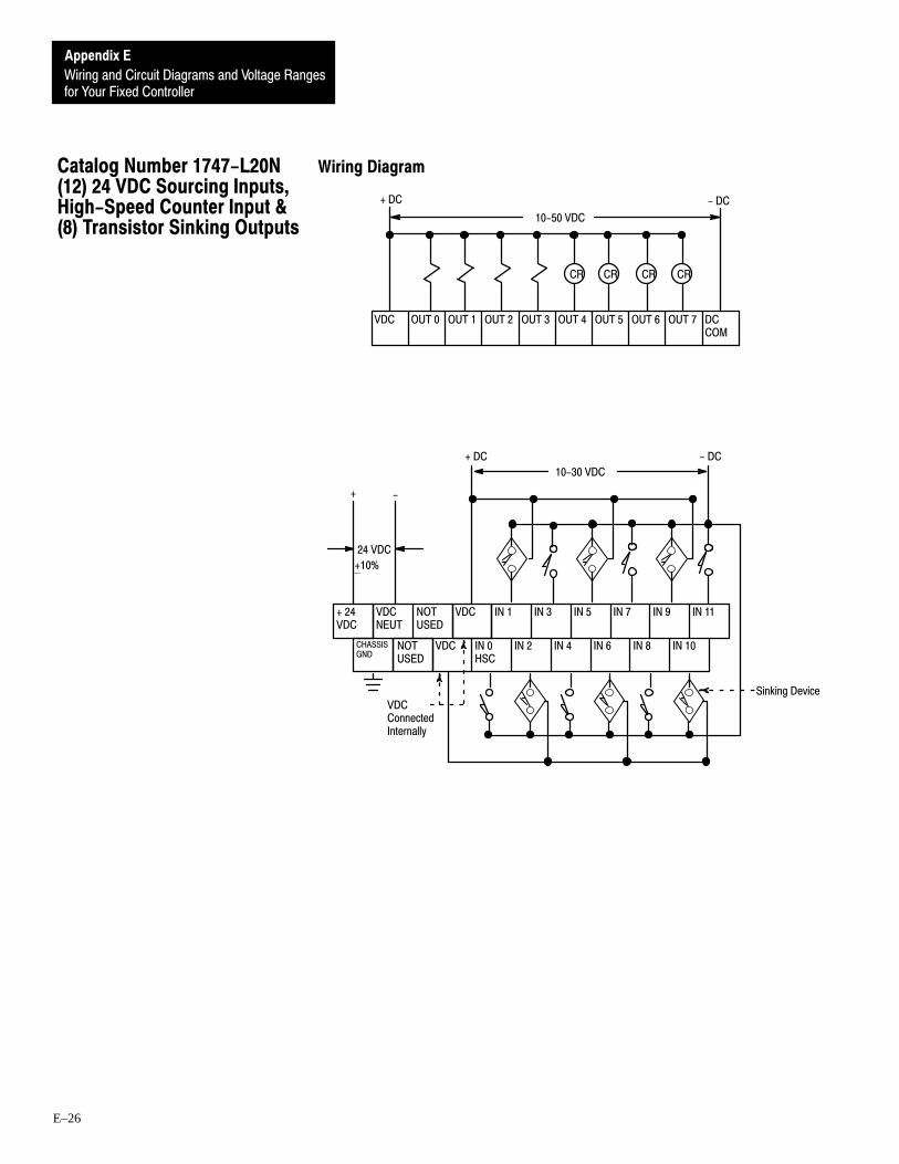
for Your Fixed Controller
Appendix E
Wiring and Circuit Diagrams and Voltage Ranges
E–26
Wiring Diagram
OUT 2 OUT 3 OUT 4 OUT 5 OUT 6 OUT 7 DCCOM
VDC OUT 1
10-50 VDC
CR
OUT 0
+ DC - DC
CR CR CR
VDCNEUT
IN 1 IN 3 IN 5 IN 7 IN 9 IN 11
CHASSISGND
VDC IN 0HSC
IN 2 IN 4 IN 6 IN 8 IN 10
+ 24VDC
NOTUSED
-+
24 VDC
VDCConnectedInternally
- DC+ DC
NOTUSED
10-30 VDC
Sinking Device
VDC
+10%
Catalog Number 1747-L20N(12) 24 VDC Sourcing Inputs,High-Speed Counter Input &(8) Transistor Sinking Outputs

for Your Fixed Controller
Appendix E
Wiring and Circuit Diagrams and Voltage Ranges
E–27
Input Circuit Diagram
3 9 0
VDC
1 . 5 K 1 . 5 K
5 6 00.1µF
INPUT 0(HSC)
OTHERINPUTS
5 6 0 5 6 0
0.01µF
On/Off State Voltage Ranges – Input 0 (HSC)
On-stateOff-state
0 VDC 4 VDC 30 VDC10 VDC
ÉÉÉÉÉÉÉÉÉÉ
Input State NotGuaranteed
On/Off State Voltage Ranges – All Other Inputs
On-stateOff-state
0 VDC 5 VDC 30 VDC10 VDC
ÉÉÉÉÉÉÉÉÉÉInput State Not
Guaranteed

for Your Fixed Controller
Appendix E
Wiring and Circuit Diagrams and Voltage Ranges
E–28
Output Circuit Diagram
VDC
OUT
DC COM
OUT
Operating Voltage Range
ÉÉÉÉÉÉÉÉÉÉÉÉ
Recommended Operating Range
0 VDC 50 VDC10 VDC
Operation NotGuaranteed
(Voltage is applied between +VDC and DC common.)

for Your Fixed Controller
Appendix E
Wiring and Circuit Diagrams and Voltage Ranges
E–29
Wiring Diagram
OUT 2 OUT 3 VAC 2 OUT 4 OUT 5 OUT 6 OUT 7VAC 1
VACNEUT
NOTUSED
ACCOM
IN 1 IN 3 IN 5 IN 7 IN 9 IN 11
CHASSISGND
NOTUSED
ACCOM
IN 0 IN 2 IN 4 IN 6 IN 8 IN 10
120/240VAC
OUT 1
CR CR
OUT 0
(Lo)L2
(Hi)L1
(Hi)L1
CR CR
(Lo)L2
170-265 VAC
(Lo)L2
(Hi)L1
(Lo)L2
(Hi)L1
85-265VAC
CommonsConnectedInternally
85-265 VAC1
85-265 VAC1
➀ These outputs are isolated in groups as shown. Therefore, different voltages can be applied to each group asthe specific application requires.
Catalog Number 1747-L20P(12) 240 VAC Inputs & (8) TriacOutputs

for Your Fixed Controller
Appendix E
Wiring and Circuit Diagrams and Voltage Ranges
E–30
Input Circuit Diagram
2 7 0
2 6 11µF
1 8 7 0
I N
I N
2 7 0
1µF
1 8 7 0
2 6 1
0.15µF
0.15µF
AC COM
On/Off State Voltage Ranges
0 VAC 50 VAC 265 VAC170 VAC
ÉÉÉÉÉÉÉÉÉÉÉÉÉÉÉÉÉÉÉÉÉÉÉÉ
On-stateInput State Not GuaranteedOff-state
Output Circuit Diagram
L1
OUT
OUT
Operating Voltage Range
ÉÉÉÉÉÉÉÉÉÉÉÉÉÉÉÉÉÉ
Recommended Operating Range
0 VAC 265 VAC
Operation Not Guaranteed
85 VAC
Important: If you measure the voltage at an output terminal that is not connected to a load or is connected to a high-impedanceload, you may measure as much as 100 VAC even though the output is off.
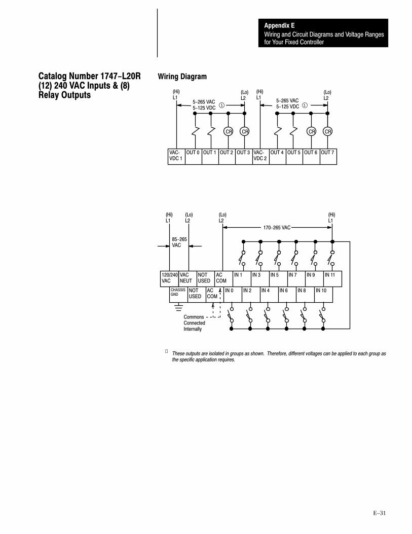
for Your Fixed Controller
Appendix E
Wiring and Circuit Diagrams and Voltage Ranges
E–31
Wiring Diagram
OUT 2 OUT 3 VACVDC 2
OUT 4 OUT 5 OUT 6 OUT 7VACVDC 1
1 15-265 VAC5-125 VDC
OUT 1
CR CR
OUT 0
(Lo)L2
(Hi)L1
(Hi)L1
CR CR
(Lo)L2
VACNEUT
NOTUSED
ACCOM
IN 1 IN 3 IN 5 IN 7 IN 9 IN 11
CHASSISGND
NOTUSED
ACCOM
IN 0 IN 2 IN 4 IN 6 IN 8 IN 10
120/240VAC
170-265 VAC
(Lo)L2
(Hi)L1
(Lo)L2
(Hi)L1
85-265VAC
CommonsConnectedInternally
5-265 VAC5-125 VDC
➀ These outputs are isolated in groups as shown. Therefore, different voltages can be applied to each group asthe specific application requires.
Catalog Number 1747-L20R(12) 240 VAC Inputs & (8)Relay Outputs

for Your Fixed Controller
Appendix E
Wiring and Circuit Diagrams and Voltage Ranges
E–32
Input Circuit Diagram
2 7 0
2 6 11µF
1 8 7 0
I N
I N
2 7 0
1µF
1 8 7 0
2 6 1
0.15µF
0.15µF
AC COM
On/Off State Voltage Ranges
0 VAC 50 VAC 265 VAC170 VAC
ÉÉÉÉÉÉÉÉÉÉÉÉÉÉÉÉÉÉÉÉÉÉÉÉ
On-stateInput State Not GuaranteedOff-state
Output Circuit Diagram
VAC/VDC
OUT
OUT
Operating Voltage Range
ÉÉÉÉ Recommended Operating Range
265 VAC
Operation NotGuaranteed
125 VDC0 V 5 VDC0 V 5 VAC

for Your Fixed Controller
Appendix E
Wiring and Circuit Diagrams and Voltage Ranges
E–33
Wiring Diagram
OUT 2 OUT 3 VACVDC 2
OUT 4 OUT 5 NOTUSED
NOTUSED
VACVDC 3
OUT 6VACVDC 1
1
1
1
VACVDC 4
1
OUT 1 OUT 7 OUT 8 OUT 9
CR CR CR
OUT 0
(Lo)L2
(Hi)L1
(Hi)L1
(Lo)L2
CR CR
(Hi)L1
(Lo)L2
NOTUSED
NOTUSED
CR
(Hi)L1
(Lo)L2
OUT 10 OUT 11
VACNEUT
NOTUSED
ACCOM
ACCOM
IN 1 IN 3 IN 5 IN 7 IN 9 IN 11 IN 13 IN 15 IN 17 NOTUSED
NOTUSED
NOTUSED
CHASSISGND
NOTUSED
ACCOM
ACCOM
IN 0 IN 2 IN 4 IN 6 IN 8 IN 10 IN 12 IN 14 IN 16 NOTUSED
NOTUSED
NOTUSED
120/240VAC
85 - 132 VAC
(Lo)L2
(Hi)L1
(Lo)L2
(Hi)L1
CommonsConnectedInternally
5-265 VAC5-125 VDC
5-265 VAC5-125 VDC
5-265 VAC5-125 VDC
5-265 VAC5-125 VDC
85-265VAC
➀ These outputs are isolated in groups as shown. Therefore, different voltages can be applied to each group asthe specific application requires.
Catalog Number 1747-L30A(18) 120 VAC Inputs & (12)Relay Outputs

for Your Fixed Controller
Appendix E
Wiring and Circuit Diagrams and Voltage Ranges
E–34
Input Circuit Diagram
2 7 0
2 6 11µF
1 8 7 0
I N
I N
2 7 0
1µF
1 8 7 0
2 6 1
0.15µF
0.15µF
AC COM
On/Off State Voltage Ranges
ÉÉÉÉÉÉÉÉÉÉÉÉÉÉÉÉÉÉÉÉÉÉÉÉ
On-state
0 VAC 30 VAC 132 VAC
Input State Not Guaranteed
85 VAC
Off-state
Output Circuit Diagram
VAC/VDC
OUT
OUT
Operating Voltage Range
ÉÉÉÉ
Recommended Operating Range
265 VAC
Operation NotGuaranteed
125 VDC0 V 5 VDC0 V 5 VAC

for Your Fixed Controller
Appendix E
Wiring and Circuit Diagrams and Voltage Ranges
E–35
Wiring Diagram
VAC 1 OUT 0 OUT 1 OUT 2 OUT 3 OUT 4 OUT 5 NOTUSED
NOTUSED
VAC 2 VAC 2VAC 1 OUT 6 OUT 7 OUT 8 OUT 9 OUT 10 OUT 11 NOTUSED
NOTUSED
(Hi)L1
CR CR
(Lo)L2
VAC 1ConnectedInternally
VAC 2ConnectedInternally
CR CR CR CR
(Hi)L1
(Lo)L2
VACNEUT
NOTUSED
ACCOM
ACCOM
IN 1 IN 3 IN 5 IN 7 IN 9 IN 11 IN 13 IN 15 IN 17 NOTUSED
NOTUSED
NOTUSED
CHASSISGND
NOTUSED
ACCOM
ACCOM
IN 0 IN 2 IN 4 IN 6 IN 8 IN 10 IN 12 IN 14 IN 16 NOTUSED
NOTUSED
NOTUSED
120/240VAC
85-132 VAC
(Lo)L2
(Hi)L1
(Lo)L2
(Hi)L1
85 - 265VAC
CommonsConnectedInternally
85-265 VAC 85-265 VAC 11
➀ These outputs are isolated in groups as shown. Therefore, different voltages can be applied to each group asthe specific application requires.
Catalog Number 1747-L30B(18) 120 Vac Inputs & (12)Triac Outputs

for Your Fixed Controller
Appendix E
Wiring and Circuit Diagrams and Voltage Ranges
E–36
Input Circuit Diagram
2 7 0
2 6 11µF
1 8 7 0
I N
I N
2 7 0
1µF
1 8 7 0
2 6 1
0.3 µF
AC COM
0.3 µF
On/Off State Voltage Ranges
ÉÉÉÉÉÉÉÉÉÉÉÉÉÉÉÉÉÉÉÉÉÉÉÉ
On-state
0 VAC 30 VAC 132 VAC
Input State Not Guaranteed
85 VAC
Off-state
Output Circuit Diagram
L1
OUT
OUT
Operating Voltage Range
ÉÉÉÉÉÉÉÉÉÉÉÉÉÉÉÉÉÉ
Recommended Operating Range
0 VAC 265 VAC
Operation Not Guaranteed
85 VAC
Important: If you measure the voltage at an output terminal that is not connected to a load or is connected to a high-impedanceload, you may measure as much as 100 VAC even though the output is off.

for Your Fixed Controller
Appendix E
Wiring and Circuit Diagrams and Voltage Ranges
E–37
Wiring Diagram
PWR OUT+24VDC
OUT 2 OUT 3 VACVDC 2
OUT 4 OUT 5 NOTUSED
NOTUSED
VACVDC 3
OUT 6VACVDC 1
1
VACVDC 4
OUT 1 OUT 7 OUT 8 OUT 9
CR CR CR
OUT 0
(Lo)L2
(Hi)L1
(Hi)L1
CR CR
(Hi)L1
(Lo)L2
NOTUSED
NOTUSED
CR
(Hi)L1
(Lo)L2
OUT 10 OUT 11
1
VACNEUT
DCCOM
DCCOM
IN 1 IN 3 IN 5 IN 7 IN 9 IN 11 IN 13 IN 15 IN 17 NOTUSED
NOTUSED
NOTUSED
CHASSISGND
DCCOM
DCCOM
IN 0HSC
IN 2 IN 4 IN 6 IN 8 IN 10 IN 12 IN 14 IN 16 NOTUSED
NOTUSED
NOTUSED
120/240VAC 2
2
(Lo)L2
(Hi)L1
85-265VAC
CommonsConnectedInternally
PWR OUTCOM
10-30 VDC
- DC + DC
SourcingDevice
(Lo)L2
1 15-265 VAC5-125 VDC
5-265 VAC5-125 VDC
5-265 VAC5-125 VDC
5-265 VAC5-125 VDC
➀ The outputs are isolated in groups as shown. Therefore, different voltages can be applied to each group asthe specific application requires.
➁ 24 VDC, 200mA user power is available for sensors.
Catalog Number 1747-L30C(18) 24 VDC Sinking Inputs,High-Speed Counter Input &(12) Relay Outputs

for Your Fixed Controller
Appendix E
Wiring and Circuit Diagrams and Voltage Ranges
E–38
Input Circuit Diagram
3 9 0
COM
1 . 5 K 1 . 5 K
5 6 0
0.01µF
0.1µF
5 6 0 5 6 0INPUT 0
OTHERINPUTS
(HSC)
On/Off State Voltage Ranges – Input 0 (HSC)
On-stateOff-state
0 VDC 4 VDC 30 VDC10 VDC
ÉÉÉÉÉÉÉÉÉÉÉÉ
Input State NotGuaranteed
On/Off State Voltage Ranges – All Other Inputs
On-stateOff-state
0 VDC 5 VDC 30 VDC10 VDC
ÉÉÉÉÉÉÉÉÉÉInput State Not
Guaranteed
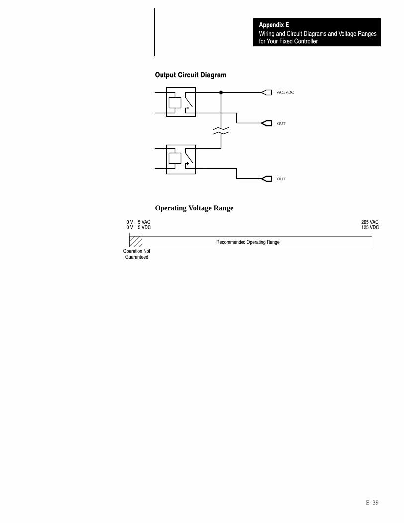
for Your Fixed Controller
Appendix E
Wiring and Circuit Diagrams and Voltage Ranges
E–39
Output Circuit Diagram
VAC/VDC
OUT
OUT
Operating Voltage Range
ÉÉÉÉ
Recommended Operating Range
265 VAC
Operation NotGuaranteed
125 VDC0 V 5 VDC0 V 5 VAC
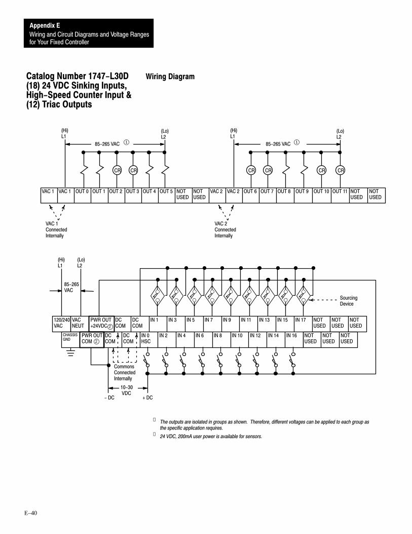
for Your Fixed Controller
Appendix E
Wiring and Circuit Diagrams and Voltage Ranges
E–40
Wiring Diagram
VAC 1 OUT 0 OUT 1 OUT 2 OUT 3 OUT 4 OUT 5 NOTUSED
NOTUSED
VAC 2 VAC 2VAC 1 OUT 6 OUT 7 OUT 8 OUT 9 OUT 10 OUT 11 NOTUSED
NOTUSED
(Hi)L1
CR CR
(Lo)L2
VAC 1ConnectedInternally
VAC 2ConnectedInternally
CR CR CR CR
(Hi)L1
(Lo)L2
85-265 VAC 85-265 VAC1 1
PWR OUT+24VDC
VACNEUT
DCCOM
DCCOM
IN 1 IN 3 IN 5 IN 7 IN 9 IN 11 IN 13 IN 15 IN 17 NOTUSED
NOTUSED
NOTUSED
CHASSISGND
DCCOM
DCCOM
IN 0HSC
IN 2 IN 4 IN 6 IN 8 IN 10 IN 12 IN 14 IN 16 NOTUSED
NOTUSED
NOTUSED
120/240VAC 2
2
(Lo)L2
(Hi)L1
85-265VAC
CommonsConnectedInternally
PWR OUTCOM
10-30 VDC
- DC + DC
SourcingDevice
➀ The outputs are isolated in groups as shown. Therefore, different voltages can be applied to each group asthe specific application requires.
➁ 24 VDC, 200mA user power is available for sensors.
Catalog Number 1747-L30D(18) 24 VDC Sinking Inputs,High-Speed Counter Input &(12) Triac Outputs

for Your Fixed Controller
Appendix E
Wiring and Circuit Diagrams and Voltage Ranges
E–41
Input Circuit Diagram
3 9 0
COM
1 . 5 K 1 . 5 K
5 6 0
0.01µF
0.1µF
5 6 0 5 6 0INPUT 0
OTHERINPUTS
(HSC)
On/Off State Voltage Ranges – Input 0 (HSC)
On-stateOff-state
0 VDC 4 VDC 30 VDC10 VDC
ÉÉÉÉÉÉÉÉÉÉ
Input State NotGuaranteed
On/Off State Voltage Ranges – All Other Inputs
On-stateOff-state
0 VDC 5 VDC 30 VDC10 VDC
ÉÉÉÉÉÉÉÉÉÉInput State Not
Guaranteed
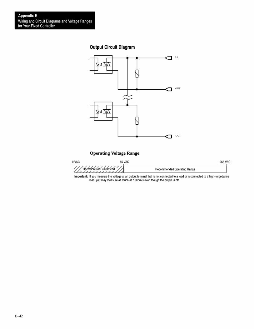
for Your Fixed Controller
Appendix E
Wiring and Circuit Diagrams and Voltage Ranges
E–42
Output Circuit Diagram
L1
OUT
OUT
Operating Voltage Range
ÉÉÉÉÉÉÉÉÉÉÉÉÉÉÉÉÉÉ
Recommended Operating Range
0 VAC 265 VAC
Operation Not Guaranteed
85 VAC
Important: If you measure the voltage at an output terminal that is not connected to a load or is connected to a high-impedanceload, you may measure as much as 100 VAC even though the output is off.

for Your Fixed Controller
Appendix E
Wiring and Circuit Diagrams and Voltage Ranges
E–43
Wiring Diagram
PWR OUT+24VDC
OUT 2 OUT 3 OUT 4 OUT 5 NOTUSED
NOTUSED
DCCOM 1
VDC 2 OUT 6VDC 1
1 1
OUT 1 OUT 7 OUT 8 OUT 9 OUT 10 OUT 11 NOTUSED
NOTUSED
DCCOM 2
CR CR
10-50 VDC
CR CR CR CR
OUT 0
+ DC - DC + DC - DC
10-50 VDC
VACNEUT
VDC VDC IN 1 IN 3 IN 5 IN 7 IN 9 IN 11 IN 13 IN 15 IN 17 NOTUSED
NOTUSED
NOTUSED
CHASSISGND
VDC VDC IN 0HSC
IN 2 IN 4 IN 6 IN 8 IN 10 IN 12 IN 14 IN 16 NOTUSED
NOTUSED
NOTUSED
120/240VAC 2
2
(Lo)L2
(Hi)L1
VDCConnectedInternally
PWR OUTCOM
10-30 VDC
+ DC - DC
Sinking Device
85-265VAC
➀ The outputs are isolated in groups as shown. Therefore, different voltages can be applied to each group asthe specific application requires.
➁ 24 VDC, 200mA user power is available for sensors.
Catalog Number 1747-L30L(18) 24 VDC Sourcing Inputs,High-Speed Counter Input &(12) Transistor SinkingOutputs
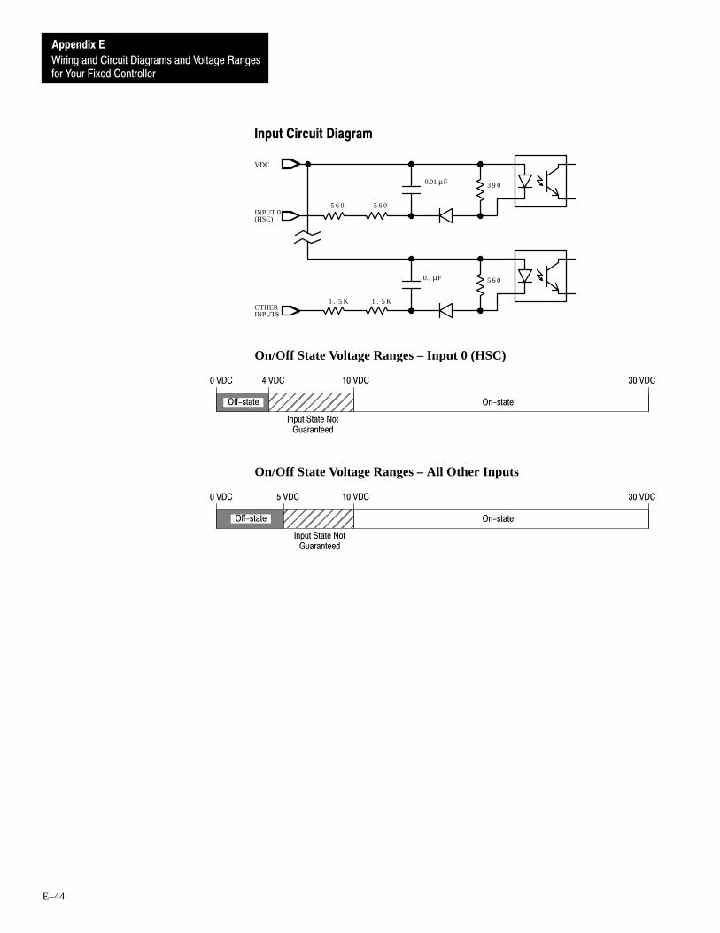
for Your Fixed Controller
Appendix E
Wiring and Circuit Diagrams and Voltage Ranges
E–44
Input Circuit Diagram
3 9 0
VDC
1 . 5 K 1 . 5 K
5 6 00.1µF
INPUT 0(HSC)
OTHERINPUTS
5 6 0 5 6 0
0.01µF
On/Off State Voltage Ranges – Input 0 (HSC)
On-stateOff-state
0 VDC 4 VDC 30 VDC10 VDC
ÉÉÉÉÉÉÉÉÉÉÉÉ
Input State NotGuaranteed
On/Off State Voltage Ranges – All Other Inputs
On-stateOff-state
0 VDC 5 VDC 30 VDC10 VDC
ÉÉÉÉÉÉÉÉÉÉInput State Not
Guaranteed
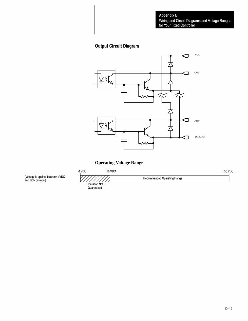
for Your Fixed Controller
Appendix E
Wiring and Circuit Diagrams and Voltage Ranges
E–45
Output Circuit Diagram
VDC
OUT
DC COM
OUT
Operating Voltage Range
ÉÉÉÉÉÉÉÉÉÉÉÉ
Recommended Operating Range
0 VDC 50 VDC10 VDC
Operation NotGuaranteed
(Voltage is applied between +VDCand DC common.)
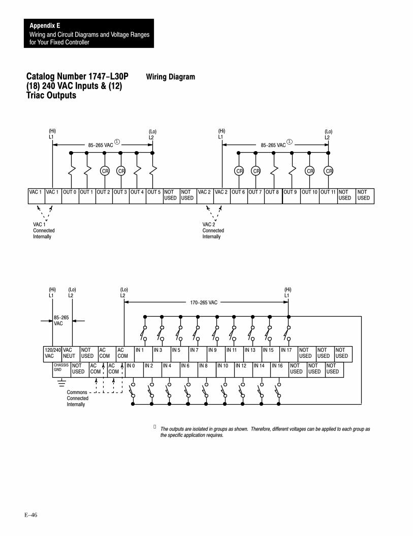
for Your Fixed Controller
Appendix E
Wiring and Circuit Diagrams and Voltage Ranges
E–46
Wiring Diagram
VAC 1 OUT 0 OUT 1 OUT 2 OUT 3 OUT 4 OUT 5 NOTUSED
NOTUSED
VAC 2 VAC 2VAC 1 OUT 6 OUT 7 OUT 8 OUT 9 OUT 10 OUT 11 NOTUSED
NOTUSED
(Hi)L1
CR CR
(Lo)L2
85-265 VAC
VAC 1ConnectedInternally
VAC 2ConnectedInternally
CR CR CR CR
(Hi)L1
(Lo)L2
VACNEUT
NOTUSED
ACCOM
ACCOM
IN 1 IN 3 IN 5 IN 7 IN 9 IN 11 IN 13 IN 15 IN 17 NOTUSED
NOTUSED
NOTUSED
CHASSISGND
NOTUSED
ACCOM
ACCOM
IN 0 IN 2 IN 4 IN 6 IN 8 IN 10 IN 12 IN 14 IN 16 NOTUSED
NOTUSED
NOTUSED
120/240VAC
170-265 VAC
(Lo)L2
(Hi)L1
(Lo)L2
(Hi)L1
CommonsConnectedInternally
85-265 VAC
85-265VAC
11
➀ The outputs are isolated in groups as shown. Therefore, different voltages can be applied to each group asthe specific application requires.
Catalog Number 1747-L30P(18) 240 VAC Inputs & (12)Triac Outputs

for Your Fixed Controller
Appendix E
Wiring and Circuit Diagrams and Voltage Ranges
E–47
Input Circuit Diagram
2 7 0
2 6 11µF
1 8 7 0
I N
I N
2 7 0
1µF
1 8 7 0
2 6 1
0.15µF
0.15µF
AC COM
On/Off State Voltage Ranges
0 VAC 50 VAC 265 VAC170 VAC
ÉÉÉÉÉÉÉÉÉÉÉÉÉÉÉÉÉÉÉÉÉÉÉÉ
On-stateInput State Not GuaranteedOff-state
Output Circuit Diagram
L1
OUT
OUT
Operating Voltage Range
ÉÉÉÉÉÉÉÉÉÉÉÉÉÉÉÉÉÉ
Recommended Operating Range
0 VAC 265 VAC
Operation Not Guaranteed
85 VAC
Important: If you measure the voltage at an output terminal that is not connected to a load or is connected to a high-impedanceload, you may measure as much as 100 VAC even though the output is off.
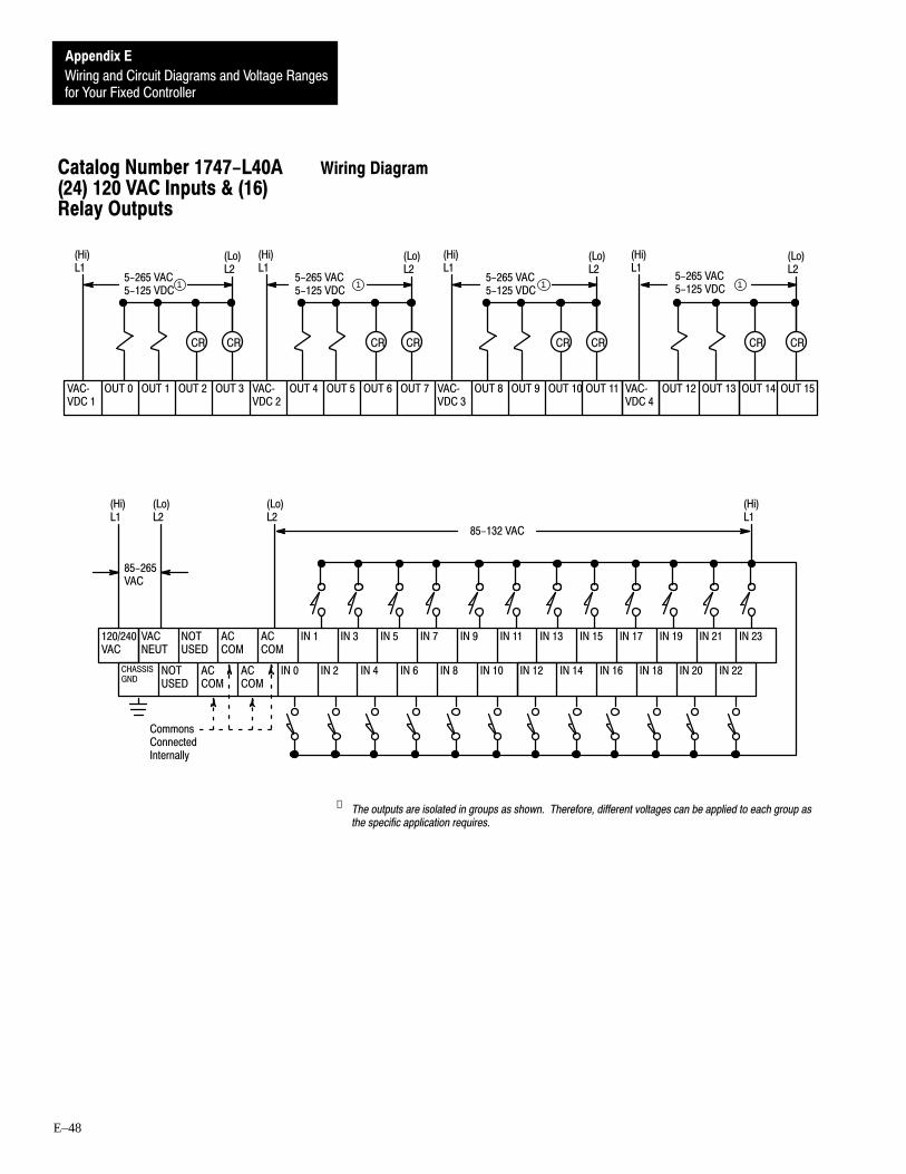
for Your Fixed Controller
Appendix E
Wiring and Circuit Diagrams and Voltage Ranges
E–48
Wiring Diagram
OUT 2 OUT 3 VACVDC 2
OUT 4 OUT 5 OUT 6 OUT 7 VACVDC 3
OUT 8VACVDC 1
1 1 1
VACVDC 4
1
OUT 1 OUT 9 OUT 10 OUT 11
CR CR CR CR
OUT 0
(Lo)L2
(Hi)L1
(Hi)L1
(Lo)L2
CR CR
(Hi)L1
(Lo)L2
OUT 14 OUT 15
CR CR
(Hi)L1
(Lo)L2
OUT 12 OUT 13
VACNEUT
NOTUSED
ACCOM
ACCOM
IN 1 IN 3 IN 5 IN 7 IN 9 IN 11 IN 13 IN 15 IN 17 IN 19 IN 21 IN 23
CHASSISGND
NOTUSED
ACCOM
ACCOM
IN 0 IN 2 IN 4 IN 6 IN 8 IN 10 IN 12 IN 14 IN 16 IN 18 IN 20 IN 22
120/240VAC
(Lo)L2
(Hi)L1
(Lo)L2
(Hi)L1
CommonsConnectedInternally
85-265VAC
5-265 VAC5-125 VDC
5-265 VAC5-125 VDC
5-265 VAC5-125 VDC
5-265 VAC5-125 VDC
85-132 VAC
➀ The outputs are isolated in groups as shown. Therefore, different voltages can be applied to each group asthe specific application requires.
Catalog Number 1747-L40A(24) 120 VAC Inputs & (16)Relay Outputs

for Your Fixed Controller
Appendix E
Wiring and Circuit Diagrams and Voltage Ranges
E–49
Input Circuit Diagram
2 7 0
2 6 1
1 8 7 0
I N
I N
2 7 0 1 8 7 0
2 6 1
0.3µF
0.3µF
1µF
1µF
AC COM
On/Off State Voltage Ranges
ÉÉÉÉÉÉÉÉÉÉÉÉÉÉÉÉÉÉÉÉÉÉÉÉ
On-state
0 VAC 30 VAC 132 VAC
Input State Not Guaranteed
85 VAC
Off-state
Output Circuit Diagram
VAC/VDC
OUT
OUT
Operating Voltage Range
ÉÉÉÉ
Recommended Operating Range
265 VAC
Operation NotGuaranteed
125 VDC0 V 5 VDC0 V 5 VAC

for Your Fixed Controller
Appendix E
Wiring and Circuit Diagrams and Voltage Ranges
E–50
Wiring Diagram
VACNEUT
NOTUSED
ACCOM
ACCOM
IN 1 IN 3 IN 5 IN 7 IN 9 IN 11 IN 13 IN 15 IN 17 IN 19 IN 21 IN 23
CHASSISGND
NOTUSED
ACCOM
ACCOM
IN 0 IN 2 IN 4 IN 6 IN 8 IN 10 IN 12 IN 14 IN 16 IN 18 IN 20 IN 22
120/240VAC
VAC 1 OUT 0 OUT 1 OUT 2 OUT 3 OUT 4 OUT 5 OUT 6 OUT 7 VAC 2 VAC 2VAC 1
(Lo)L2
(Hi)L1
(Lo)L2
(Hi)L1
CommonsConnectedInternally
OUT 8 OUT 9 OUT 10 OUT 11 OUT 12 OUT 13 OUT 14 OUT 15
(Hi)L1
CR CR CR CR
(Lo)L2
VAC 1ConnectedInternally
VAC 2ConnectedInternally
CR CR CR CR
(Hi)L1
(Lo)L2
85-265VAC
85-265 VAC 85-265 VAC
85-132 VAC
11
➀ The outputs are isolated in groups as shown. Therefore, different voltages can be applied to each group asthe specific application requires.
Catalog Number 1747-L40B(24) 120 VAC Inputs & (16)Triac Outputs

for Your Fixed Controller
Appendix E
Wiring and Circuit Diagrams and Voltage Ranges
E–51
Input Circuit Diagram
2 7 0
2 6 1
1 8 7 0
I N
I N
2 7 0 1 8 7 0
2 6 1
0.3µF
0.3µF
1µF
1µF
AC COM
On/Off State Voltage Ranges
ÉÉÉÉÉÉÉÉÉÉÉÉÉÉÉÉÉÉÉÉÉÉÉÉ
On-state
0 VAC 30 VAC 132 VAC
Input State Not Guaranteed
85 VAC
Off-state
Output Circuit Diagram
L1
OUT
OUT
Operating Voltage Range
ÉÉÉÉÉÉÉÉÉÉÉÉÉÉÉÉÉÉ Recommended Operating Range
0 VAC 265 VAC
Operation Not Guaranteed
85 VAC
Important: If you measure the voltage at an output terminal that is not connected to a load or is connected to a high-impedanceload, you may measure as much as 100 VAC even though the output is off.

for Your Fixed Controller
Appendix E
Wiring and Circuit Diagrams and Voltage Ranges
E–52
Wiring Diagram
PWR OUT+24VDC
OUT 2 OUT 3 VACVDC 2
OUT 4 OUT 5 OUT 6 OUT 7 VACVDC 3
OUT 8VACVDC 1
1 1 1
VACVDC 4
1
OUT 1 OUT 9 OUT 10 OUT 11
CR CR CR CR
OUT 0
(Lo)L2
(Hi)L1
(Hi)L1
(Lo)L2
CR CR
(Hi)L1
(Lo)L2
OUT 14 OUT 15
CR CR
(Hi)L1
(Lo)L2
OUT 12 OUT 13
VACNEUT
DCCOM
DCCOM
IN 1 IN 3 IN 5 IN 7 IN 9 IN 11 IN 13 IN 15 IN 17 IN 19 IN 21 IN 23
CHASSISGND
DCCOM
DCCOM
IN 0HSC
IN 2 IN 4 IN 6 IN 8 IN 10 IN 12 IN 14 IN 16 IN 18 IN 20 IN 22
120/240VAC 2
2
(Lo)L2
(Hi)L1
CommonsConnectedInternally
PWR OUTCOM
10-30 VDC
+ DC- DC
Sourcing Device
85-265VAC
5-265 VAC5-125 VDC
5-265 VAC5-125 VDC
5-265 VAC5-125 VDC
5-265 VAC5-125 VDC
➀ The outputs are isolated in groups as shown. Therefore, different voltages can be applied to each group asthe specific application requires.
➁ 24 VDC, 200mA user power is available for sensors.
Catalog Number 1747-L40C(24) 24 VDC Sinking Inputs,High-Speed Counter Input &(16) Relay Outputs

for Your Fixed Controller
Appendix E
Wiring and Circuit Diagrams and Voltage Ranges
E–53
Input Circuit Diagram
3 9 0
COM
1 . 5 K 1 . 5 K
5 6 0
0.01µF
0.1µF
5 6 0 5 6 0INPUT 0
OTHERINPUTS
(HSC)
On/Off State Voltage Ranges – Input 0 (HSC)
On-stateOff-state
0 VDC 4 VDC 30 VDC10 VDC
ÉÉÉÉÉÉÉÉÉÉ
Input State NotGuaranteed
On/Off State Voltage Ranges – All Other Inputs
On-stateOff-state
0 VDC 5 VDC 30 VDC10 VDC
ÉÉÉÉÉÉÉÉÉÉInput State Not
Guaranteed

for Your Fixed Controller
Appendix E
Wiring and Circuit Diagrams and Voltage Ranges
E–54
Output Circuit Diagram
VAC/VDC
OUT
OUT
Operating Voltage Range
ÉÉÉÉ
Recommended Operating Range
265 VAC
Operation NotGuaranteed
125 VDC0 V 5 VDC0 V 5 VAC

for Your Fixed Controller
Appendix E
Wiring and Circuit Diagrams and Voltage Ranges
E–55
Wiring Diagram
PWR OUT+24VDC
OUT 2 OUT 3 OUT 4 OUT 5 OUT 6 OUT 7 DCCOM 1
VDC 2 OUT 8VDC 1
1 1
OUT 1 OUT 9 OUT 10 OUT 11 OUT 12 OUT 13 OUT 14 OUT 15 DCCOM 2
CR CR CR CR
10-50 VDC
CR CR CR CR
OUT 0
+ DC - DC + DC - DC
VACNEUT
DCCOM
DCCOM
IN 1 IN 3 IN 5 IN 7 IN 9 IN 11 IN 13 IN 15 IN 17 IN 19 IN 21 IN 23
CHASSISGND
DCCOM
DCCOM
IN 0HSC
IN 2 IN 4 IN 6 IN 8 IN 10 IN 12 IN 14 IN 16 IN 18 IN 20 IN 22
120/240VAC 2
2
(Lo)L2
(Hi)L1
CommonsConnectedInternally
PWR OUTCOM
10-30 VDC
+ DC- DC
Sourcing Device
85-265VAC
10-50 VDC
➀ The outputs are isolated in groups as shown. Therefore, different voltages can be applied to each group asthe specific application requires.
➁ 24 VDC, 200mA user power is available for sensors.
Catalog Number 1747-L40E(24) 24 VDC Sinking Inputs,High-Speed Counter Input &(16) Transistor SourcingOutputs

for Your Fixed Controller
Appendix E
Wiring and Circuit Diagrams and Voltage Ranges
E–56
Input Circuit Diagram
3 9 0
COM
1 . 5 K 1 . 5 K
5 6 0
0.01µF
0.1µF
5 6 0 5 6 0INPUT 0
OTHERINPUTS
(HSC)
On/Off State Voltage Ranges – Input 0 (HSC)
On-stateOff-state
0 VDC 4 VDC 30 VDC10 VDC
ÉÉÉÉÉÉÉÉÉÉÉÉ
Input State NotGuaranteed
On/Off State Voltage Ranges – All Other Inputs
On-stateOff-state
0 VDC 5 VDC 30 VDC10 VDC
ÉÉÉÉÉÉÉÉÉÉInput State Not
Guaranteed
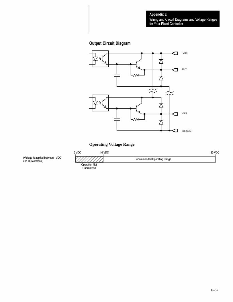
for Your Fixed Controller
Appendix E
Wiring and Circuit Diagrams and Voltage Ranges
E–57
Output Circuit Diagram
VDC
OUT
OUT
DC COM
Operating Voltage Range
ÉÉÉÉÉÉÉÉÉÉÉÉ
Recommended Operating Range
0 VDC 50 VDC10 VDC
Operation NotGuaranteed
(Voltage is applied between +VDCand DC common.)

for Your Fixed Controller
Appendix E
Wiring and Circuit Diagrams and Voltage Ranges
E–58
Wiring Diagram
NOTUSED
OUT 2 OUT 3 VACVDC 2
OUT 4 OUT 5 OUT 6 OUT 7 VACVDC 3
OUT 8VACVDC 1
1
OUT 1 OUT 9 OUT 10 OUT 11
CR CR CR CR
OUT 0
(Lo)L2
(Hi)L1
(Hi)L1
1
(Lo)L2
1
CR CR
(Hi)L1
(Lo)L2
VACVDC 4
1
OUT 14 OUT 15
CR CR
(Hi)L1
(Lo)L2
OUT 12 OUT 13
VDCNEUT
DCCOM
DCCOM
IN 1 IN 3 IN 5 IN 7 IN 9 IN 11 IN 13 IN 15 IN 17 IN 19 IN 21 IN 23
EARTHGND
DCCOM
DCCOM
IN 0HSC
IN 2 IN 4 IN 6 IN 8 IN 10 IN 12 IN 14 IN 16 IN 18 IN 20 IN 22
+ 24VDC
-+
CommonsConnectedInternally
- DC + DC
NOTUSED
10-30 VDC
Sourcing Device
24 VDC+ 10 %
5-265 VAC5-125 VDC
5-265 VAC5-125 VDC
5-265 VAC5-125 VDC
5-265 VAC5-125 VDC
➀ The outputs are isolated in groups as shown. Therefore, different voltages can be applied to each group asthe specific application requires.
Catalog Number 1747-L40F(24) 24 VDC Sinking Inputs,High-Speed Counter Input &(16) Relay Outputs

for Your Fixed Controller
Appendix E
Wiring and Circuit Diagrams and Voltage Ranges
E–59
Input Circuit Diagram
3 9 0
COM
1 . 5 K 1 . 5 K
5 6 0
0.01µF
0.1µF
5 6 0 5 6 0INPUT 0
OTHERINPUTS
(HSC)
On/Off State Voltage Ranges – Input 0 (HSC)
On-stateOff-state
0 VDC 4 VDC 30 VDC10 VDC
ÉÉÉÉÉÉÉÉÉÉ
Input State NotGuaranteed
On/Off State Voltage Ranges – All Other Inputs
On-stateOff-state
0 VDC 5 VDC 30 VDC10 VDC
ÉÉÉÉÉÉÉÉÉÉInput State Not
Guaranteed

for Your Fixed Controller
Appendix E
Wiring and Circuit Diagrams and Voltage Ranges
E–60
Output Circuit Diagram
VAC/VDC
OUT
OUT
Operating Voltage Range
ÉÉÉÉ
Recommended Operating Range
265 VAC
Operation NotGuaranteed
125 VDC0 V 5 VDC0 V 5 VAC

for Your Fixed Controller
Appendix E
Wiring and Circuit Diagrams and Voltage Ranges
E–61
Wiring Diagram
PWR OUT+24VDC
VACNEUT
VDC VDC IN 1 IN 3 IN 5 IN 7 IN 9 IN 11 IN 13 IN 15 IN 17 IN 19 IN 21 IN 23
EARTHGND
VDC VDC IN 0HSC
IN 2 IN 4 IN 6 IN 8 IN 10 IN 12 IN 14 IN 16 IN 18 IN 20 IN 22
(Lo)L2
(Hi)L1
VDCConnectedInternally
120/240VAC
OUT 1 OUT 2 OUT 3 OUT 4 OUT 5 OUT 6 OUT 7 DCCOM 1
VDC 2 OUT 8 OUT 9 OUT 10 OUT 11 OUT 12VDC 1 OUT 13 OUT 14 OUT 15 DCCOM 2
CR CR CR CR
10-50 VDC 1
CR CR CR CR
2
PWR OUTCOM 2
10-30 VDC
+ DC - DC
Sinking Device
OUT 0
+ DC - DC + DC - DC
1
85-265VAC
10-50 VDC
➀ The outputs are isolated in groups as shown. Therefore, different voltages can be applied to each group asthe specific application requires.
➁ 24 VDC, 200mA user power is available for sensors.
Catalog Number 1747-L40L(24) 24 VDC Sourcing Inputs,High-Speed Counter Input &(16) Transistor SinkingOutputs

for Your Fixed Controller
Appendix E
Wiring and Circuit Diagrams and Voltage Ranges
E–62
Input Circuit Diagram
3 9 0
VDC
1 . 5 K 1 . 5 K
5 6 00.1µF
INPUT 0(HSC)
OTHERINPUTS
5 6 0 5 6 0
0.01µF
On/Off State Voltage Ranges – Input 0 (HSC)
On-stateOff-state
0 VDC 4 VDC 30 VDC10 VDC
ÉÉÉÉÉÉÉÉÉÉÉÉ
Input State NotGuaranteed
On/Off State Voltage Ranges – All Other Inputs
On-stateOff-state
0 VDC 5 VDC 30 VDC10 VDC
ÉÉÉÉÉÉÉÉÉÉInput State Not
Guaranteed

for Your Fixed Controller
Appendix E
Wiring and Circuit Diagrams and Voltage Ranges
E–63
Output Circuit Diagram
VDC
OUT
DC COM
OUT
Operating Voltage Range
ÉÉÉÉÉÉÉÉÉÉÉÉ
Recommended Operating Range
0 VDC 50 VDC10 VDC
Operation NotGuaranteed
(Voltage is applied between +VDCand DC common.)

for Your Fixed Controller
Appendix E
Wiring and Circuit Diagrams and Voltage Ranges
E–64
Wiring Diagram
VACNEUT
NOTUSED
ACCOM
ACCOM
IN 1 IN 3 IN 5 IN 7 IN 9 IN 11 IN 13 IN 15 IN 17 IN 19 IN 21 IN 23
CHASSISGND
NOTUSED
ACCOM
ACCOM
IN 0 IN 2 IN 4 IN 6 IN 8 IN 10 IN 12 IN 14 IN 16 IN 18 IN 20 IN 22
170-265 VAC
(Lo)L2
(Hi)L1
(Lo)L2
(Hi)L1
CommonsConnectedInternally
120/240VAC
VAC 1 OUT 0 OUT 1 OUT 2 OUT 3 OUT 4 OUT 5 OUT 6 OUT 7 VAC 2 VAC 2 OUT 8 OUT 9 OUT 10 OUT 11VAC 1 OUT 12 OUT 13 OUT 14 OUT 15
(Hi)L1
CR CR CR CR
(Lo)L2
VAC 1ConnectedInternally
VAC 2ConnectedInternally
CR CR CR CR
(Hi)L1
(Lo)L2
85-265VAC
85-265 VAC 85-265 VAC1 1
➀ The outputs are isolated in groups as shown. Therefore, different voltages can be applied to each group asthe specific application requires.
Catalog Number 1747-L40P(24) 240 VAC Inputs & (16)Triac Outputs
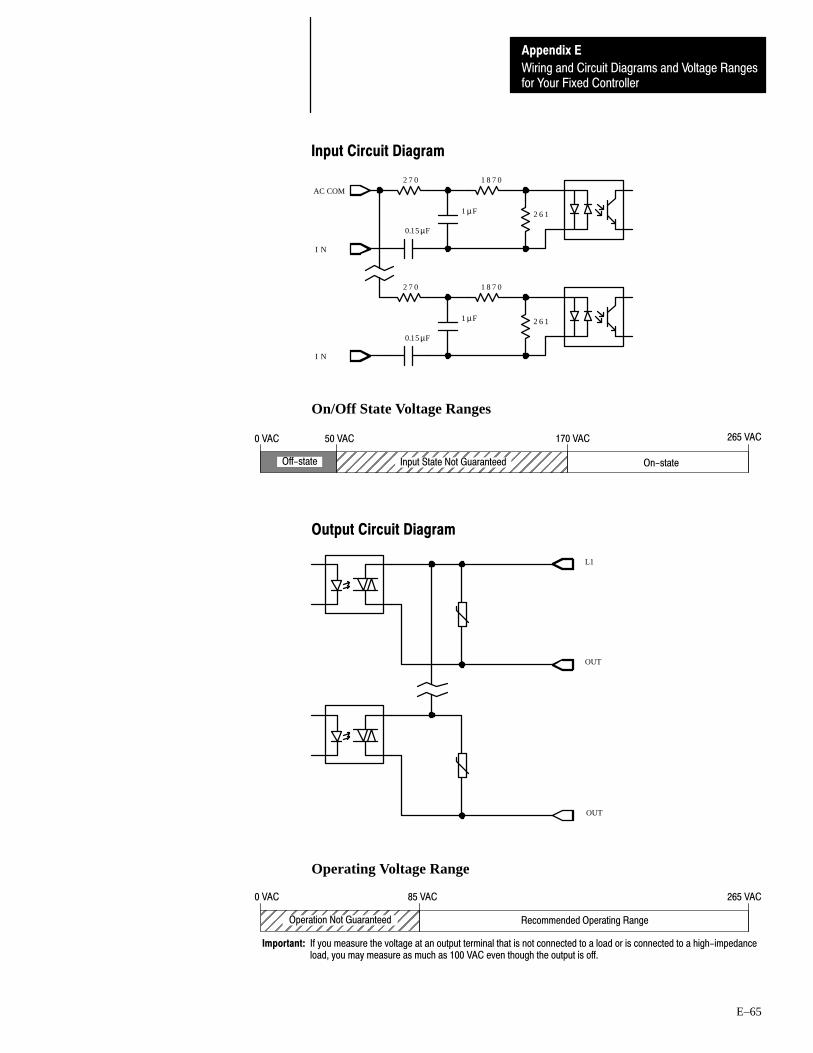
for Your Fixed Controller
Appendix E
Wiring and Circuit Diagrams and Voltage Ranges
E–65
Input Circuit Diagram
2 7 0
2 6 11µF
1 8 7 0
I N
I N
2 7 0
1µF
1 8 7 0
2 6 1
0.15µF
0.15µF
AC COM
On/Off State Voltage Ranges
0 VAC 50 VAC 265 VAC170 VAC
ÉÉÉÉÉÉÉÉÉÉÉÉÉÉÉÉÉÉÉÉÉÉÉÉ
On-stateInput State Not GuaranteedOff-state
Output Circuit Diagram
L1
OUT
OUT
Operating Voltage Range
ÉÉÉÉÉÉÉÉÉÉÉÉÉÉÉÉÉÉ
Recommended Operating Range
0 VAC 265 VAC
Operation Not Guaranteed
85 VAC
Important: If you measure the voltage at an output terminal that is not connected to a load or is connected to a high-impedanceload, you may measure as much as 100 VAC even though the output is off.


Glossary
G–1
Glossary
Auto Answer — The type of modem that has self-contained timeouts andtests. They can answer and hang the phone up automatically.
Backplane Current Draw — The amount of current the module requiresfrom the backplane. The sum of the backplane current draw for all modulesin a chassis is used to select the appropriate chassis power supply.
Baud Rate — The speed of communication between devices on a network.All devices must communicate at the same baud rate. For example, theDH–485 network devices default to 19,200 baud.
Calculated Watts — The amount of heat generated by those pointsenergized on an I/O module.
Channel — Communication port on a module.
Chassis — A hardware assembly that houses devices such as I/O modules,adapter modules, processor modules, and power supplies.
Continuous Current Per Module — The maximum current for eachmodule. The sum of the output current for each point should not exceed thisvalue.
Continuous Current Per Point — The maximum current each output isdesigned to continuously supply to a load.
CPU — Central Processing Unit or processor.
DF1 protocol — A peer–to–peer link–layer protocol that combines featuresof ANSI X3.28–1976 specification subcategories D1 (data transparency) andF1 (two–way simultaneous transmission with embedded responses).
Direct Connect — A type of modem that is connected to a dedicated, leasedphone line and is active at all times.
DH–485 Network — The DH–485 network is a collection of devicesconnected to the communication cable allowing information exchange. Acommunication network based on the EIA Standard for RS–485 using anAllen–Bradley proprietary protocol.
DTE Controlled Answer — type of modem that is unattended and isattached directly to the phone lines. The interface module or the 5/03processor acts as the Data Terminal Equipment (DTE), which controls themodem via the DTR, DSR, and DCD signals. The module incorporatestimeouts and tests to properly operate these types of modems.
Glossary
G–2
DTR Dialing (5/03 only) — type of modem that lets you dial a number orend a call based on the status of the RS–232 DTR (Data Terminal Ready)signal. To program the modem initialization string and phone number intothe internal memory of the modem, use a dumb terminal (or PC runningterminal emulation software like Procomm, Window’s Terminal, or PBASE).Once you have programmed the modem, activate the DTR signal to dial thenumber, or deactivate the DTR signal to end the call.
EEPROM — Electrically Erasable Programmable Read Only Memorymodule used to store, back up, or transfer SLC 500 programs. The SLC 500can read and write to an EEPROM.
Flash EPROM — Flash Erasable Programmable Read Only Memorymodule. It combines the programming versatility of EEPROMs with thesecurity precautions of UVPROMs. This means that you have the option ofleaving your EPROM programs write protected or unprotected.
Full–duplex — A high performance protocol that allows simultaneoustwo–way data transmission. For point–to–point applications only.
Half–duplex — A high performance protocol that can be used inpoint–to–point and multi–point applications.
Initiator — A node on the DH–485 network capable of acting as a master.When an initiator has the token it can send messages and request replies fromany node on the DH–485 network. A personal computer running the SLC500 Advanced Programming Software is an initiator on the data link. TheSLC 5/02 can also be an initiator.
Input Device — A device, such as a push button or a switch, that suppliessignals through input circuits to a programmable controller.
Inrush Current — The temporary surge current produced when a device orcircuit is initially energized.
I/O — Inputs and Outputs
Isolated Link Coupler — The link coupler provides an electrically isolatednetwork connection for an SLC 500 controller (processor or programmingstation). The link couplers connect the daisy–chained DH–485communication cable.
LED — Light Emitting Diode. Used as status indicator for processorfunctions and inputs and outputs.
Manual — typically an acoustically coupled type of modem. Theconnection is established by a person on each end of the phone line. Theythen insert the handsets into an acoustic coupler to complete the connection.
Maximum Watts — The maximum amount of heat that the modulegenerates with field power present.
Minimum Load Current — The lowest amount of current the output isdesigned to operate at. Operating at or below this value is not reliable.

Glossary
G–3
Minimum Watts — The amount of heat dissipation that can occur whenthere is no field power present.
Multi–master network — A network in which more than one node has theability to initiate communications and initialize the link.
Network — A series of stations (nodes) connected by some type ofcommunication medium. A network may be made up of a single link ormultiple links.
Node — Also called a station. An address or software location on thenetwork.
Nominal Input Current — The current at nominal input voltage.
Off–State Current — For input circuits, the maximum amount of leakagecurrent allowed from an input device in its Off–state.
Off–State Leakage — For output circuits, the maximum amount of(leakage) current that may flow when the output circuit is in its Off–state.
Off–State Voltage (max) — The maximum input voltage level detected asan Off condition by the input module.
On–State Voltage Drop — The voltage developed across the output drivercircuit during the On state at maximum load current.
Operating Voltage — For inputs, the voltage range needed for the input tobe in the On state. For outputs, the allowable range of user–supplied voltage.
Output Device — A device, such as a pilot light or a motor starter coil, thatis energized by the programmable controller.
Points per Common — The number of input or output points connected to asingle return (common) or supply (vcc).
Protocol — The “language” or packaging of information that is transmittedacross a network.
(I/O) Rack — An I/O addressing unit that corresponds to 8 inputimage–table words and 8 output image–table words. A rack can contain amaximum of 8 I/O groups for up to 128 discrete I/O.
Remote I/O Network — A network where the communication between theprocessor and the I/O is across a serial link.
Responder —A node on the DH–485 network that acts as a slave device. Aresponder is not capable of initiating communications. It can only sendmessages in response to a request from an initiator. The SLC 5/01 and 5/02can also be responders.
RS–232 — An EIA standard that specifies electrical, mechanical, andfunctional characteristics for serial binary communication circuits. Asingle–ended serial communication interface.

Glossary
G–4
RTB —Removable Terminal Block.
Signal Delay — For inputs, the response time required to transmit the circuitstatus from the field wiring to the digital logic. For outputs, the timerequired to transmit the circuit status from digital logic to the output wiring.
Sinking — A term used to describe current flow between an I/O device andSLC I/O circuit — typically, a sinking device or circuit provides a path toground, low, or negative side of power supply.
Sinking/Sourcing — Describes a current signal flow relationship betweenfield input and output devices in a control system and their power supply.Sourcing I/O modules supply (or source) current to sinking field devices.Sinking I/O modules receive (or sink) current from sourcing field devices.
Sourcing — A term used to describe current flow between an I/O deviceand SLC I/O circuit — typically, a sourcing device or circuit provides a pathto the source, high, or positive side of power supply.
Surge Current Per Point — The maximum amplitude and duration (pulse)of current allowed for a given period of time and temperature.
Surge Suppressor — A device used to absorb voltage transients created byenergizing an inductive load to reduce electrical noise or to protect the outputcircuit. For example, an R–C network, MOV (metal oxide varistor) or diode.
Token — The logical right to initiate communications. In a multi–masternetwork a single token is passed between initiators to make sure two nodesdo not transmit at the same time.
UVPROM — An Ultra–Violet light erasable Programmable Read OnlyMemory module used to back up, store, or transfer SLC 500 programs. TheSLC 5/01 and 5/02 can only read from a UVPROM. An external PROMprogrammer is used to program (write to) the device.
Voltage Category — The nominal voltage used to describe the module.
Watts Per Point — The maximum heat dissipation that can occur in eachfield wiring point when energized.

Numbers
1746-2.35, publication number, 5-7
1746-BAS module, A-3, C-2
1746-ND005, manual catalog number, A-3, C-2
1746-NM001, manual catalog number, A-3
1746-NM002, manual catalog number, A-3
1747-2.30, publication number, 1-1
1747-AIC link coupler, A-4
1747-BA, lithium batteryassembly, 9-1handling, 7-1installing, 7-4memory backup, 1-4replacing, 7-4storing, 7-1transporting, 7-2
1747-C10 cable, A-4
1747-C11 cable, A-4
1747-KE module, A-3as an RS-232 communication device,
C-2
1747-NU001, manual catalog number, A-3, C-2
1770-4.1, publication number, 2-3
1770-6.5.18, manual catalog number, C-2
1770-6.5.18, publication number, A-3
1770-KF3 module, A-3, C-2
1771-Remote I/O Network, B-1
1784-2.23, publication number, A-3
1784-KR module, A-3
1785-1.21, publication number, A-3
1785-6.5.5, publication number, A-3
1785-KA5 module, A-3
1K User Words EEPROMdefinition, G-2installing, 4-4overview, 1-11replacement part, 9-1
1K User Words UVPROMdefinition, G-4installing, 4-4overview, 1-11replacement part, 9-1
2-Slot Expansion Chassisdimensions, 3-4mounting, 4-1selecting, 1-8
20 I/O Fixed ControllerConfiguration Options, 1-5dimensions, 3-2general specifications, 1-3high-speed counter setup, 4-5Input Specifications, 1-6installation, 2-1memory module installation, 4-4Output Specifications, 1-7selecting the 2-slot expansion chassis,
1-8Troubleshooting, 8-1Wiring and Circuit Diagrams and Voltage
Range Locations, E-2
2760-ND001, publication number, A-3
2760-RB module, A-3
30 and 40 I/O Fixed ControllerConfiguration Options, 1-5dimensions, 3-3general specifications, 1-3high-speed counter setup, 4-5Input Specifications, 1-6installation, 2-1memory module installation, 4-4Output Specifications, 1-7selecting the 2-slot expansion chassis,
1-8Troubleshooting, 8-1Wiring and Circuit Diagrams and Voltage
Range Locations, E-2
4K User Words EEPROMdefinition, G-2installing, 4-4overview, 1-11
4K User Words UVPROMdefinition, G-4overview, 1-11
6001-6.5.5, publication number, A-3
A
Adaptor Socket, 1-11
Advanced Programming Software,1747-PA2E
overview, 1-10using, 6-3
Index
IndexI–2
Allen-Bradley, contacting for assistance, P-4, 8-1
Article 70B of the NFPA, 2-9
B
BASIC programming language, C-2
Belden #9842connecting to link coupler, A-11new wire/terminal connections, A-12old wire/terminal connections, A-12overview, A-9
C
cable routes, planning, A-6
cables1747-C10, A-41747-C11, A-4Belden #9842, A-9, A-11, A-12
calculated wattsdefinition, G-1overview, D-1
circuit operationinput, 8-8output, 8-10
Common Power Source, 2-7
communication interface, RS-232, C-1
Configuration Options, 1-5
contact protectiondiodes, 1-16RC network, 1-16reducing high transient arcing, 1-16surge suppressor, 1-16varistor, 1-16
contacting Allen-Bradley for assistance, P-4, 8-1
CPU fault, 8-5
CPU major error with low or no batteryback-up, 8-7
CPU major fault, 8-6
D
DCE Pinout, C-4
DH-485, token rotation, A-2
DH-485 Communication Interface user'smanual, C-2
DH-485 interface converter, 1-10
DH-485 networkdescription, A-1, G-1devices that use the, A-3example system configuration, A-5grounding and terminating, A-13initialization, A-2installation, A-9isolated link coupler, A-4protocol, A-1token rotation, A-2
DH-485/RS-232 Interface Module user'smanual, C-2
diode, 1N4004, 1-16
discrete I/O modulesfeatures, 5-5installing, 4-2replacing retainer clips, 7-6selecting, 1-8troubleshooting, 8-8, 8-10wiring, 5-7
documents referenced in this manual1746-2.35, publication number, 5-71746-ND005, catalog number, A-31746-NM001, catalog number, A-31746-NM002, catalog number, A-31747-2.30, publication number, 1-11747-NU001, catalog number, A-31770-4.1, publication number, 2-31770-6.5.18, publication number, A-31784-2.23, publication number, A-31785-1.21, publication number, A-31785-6.5.5, publication number, A-32760-RB module, publication number,
A-36001-6.5.5, publication number, A-3
DTAMdimensions, 3-5monitoring with, 1-10
DTEcontrolled answer, G-1pinout, C-4
DTR dialing, G-2
E
EEPROM memory moduledefinition, G-2installing, 4-4overview, 1-11replacement part, 9-1
Electronics Industries Association (EIA), C-1

Index I–3
Emergency-Stop Switches, 2-6
enclosuresgrounding, 2-3selecting, 1-9spacing within, 2-2
errors, 8-4
Excessive Line Voltage Variations, 1-13
Excessive Noise, 1-13
F
fuse replacement, 7-5, 8-3, 9-1
G
ground bus, 2-4
grounding guidelines, 2-3
H
Hand-Held Terminal, programming with, 1-9
heat dissipationfor control system, D-1from enclosures, 2-2worksheet for calculating, D-5
High-Speed Counterconfigurable controllers, 1-5input compatibility, 4-6operation, 4-5sinking input circuit diagram, 4-7sourcing input circuit diagram, 4-7
How to Use this Manual, P-2
I
I/O modules, wiring, 5-7
IBM AT connector pin assignment, C-6
IBM compatible computer, programmingwith, 1-9
ICCG-11.6, publication number, C-1
inadequate system power, 8-4
input circuit diagrams1747-L20A (12) 120 VAC inputs & (8)
relay outputs, E-51747-L20B (12) 120 VAC inputs & (8)
triac outputs, E-71747-L20C (12) 24 VDC sinking inputs,
high-speed counter input & (8) relayoutputs, E-9
1747-L20D 12 (24) VDC sinking inputs,high-speed counter input & (8) triacoutputs, E-12
1747-L20E (12) 24 VDC sinking inputs,high-speed counter input & (8)transistor sourcing outputs, E-15
1747-L20F (12) 24 VDC sinking inputs,high-speed counter input & (8) relayoutputs, E-18
1747-L20G (12) 24 VDC sinking inputs,high-speed counter input & (8)transistor sourcing outputs, E-21
1747-L20L (12) 24 VDC sourcing inputs,high-speed counter input & (8)transistor sinking outputs, E-24
1747-L20N (12) 24 VDC sourcing inputs,high-speed counter input & (8)transistor sinking outputs, E-27
1747-L20P (12) 24 VAC inputs & (8) triacoutputs, E-30
1747-L20R (12) 240 VAC inputs & (8)relay outputs, E-32
1747-L30A (18) 120 VAC inputs & (12)relay outputs, E-34
1747-L30B (18) 120 VAC inputs & (12)triac outputs, E-36
1747-L30C (18) 24 VDC sinking inputs,high-speed counter input & (12)relay outputs, E-38
1747-L30D (18) 24 VDC sinking inputs,high-speed counter input & (12)triac outputs, E-41
1747-L30L (18) 24 VDC sourcing inputs,high-speed counter input & (12)transistor outputs, E-44
1747-L30P (18) 240 VDC inputs & (12)triac outputs, E-47
1747-L40A (24) 120 VAC inputs & (16)relay outputs, E-49
1747-L40B (24) 120 VAC inputs & (16)triac outputs, E-51
1747-L40C (24) 24 VDC sinking inputs,high-speed counter input & (16)relay outputs, E-53
1747-L40E (24) 24 VDC sinking inputs,high-speed counter input & (16)transistor sourcing outputs, E-56
1747-L40F (24) 24 VDC sinking inputs,high-speed counter input & (16)relay outputs, E-59
1747-L40L (24) 24 VDC sourcing inputs,high-speed counter input & (16)transistor sinking outputs, E-62
1747-L40P (24) 240 VAC inputs (16) triacoutputs, E-65
Input Circuit Operation, 8-8
input modules, troubleshooting, 8-8

IndexI–4
Input Specifications, 1-6
Input States on Power Down, 2-7
installation2-slot expansion chassis, 4-1control system, 2-1I/O and speciality modules, 4-2lithium battery, 7-4memory module, 4-4
interface converter (1747-PIC), 1-10
isolated link couplerdefinition, G-2installing, A-16overview, A-4powering, A-14
isolation transformers, 1-12
L
LEDsBATTERY LOW, 1-3, 8-3CPU FAULT, 1-3, 8-3FORCED I/O, 1-3, 8-3PC RUN, 1-3, 8-3POWER, 1-3, 8-3
link couplerdefinition, G-2installing, A-16overview, A-4powering, A-14
lithium batteryassembly, 9-1handling, 7-1installing, 7-4memory backup, 1-4replacing, 7-4storing, 7-1transporting, 7-2
Loss of Power Source, 2-7
M
machine motion, preventing, 6-2
maintenance, preventive, 2-9
master control relay, 2-5
mating connector for 32 point user-madecable, 9-1
maximum wattsdefinition, G-2overview, D-1
memory modules1K User Words EEPROM, 1-11, 4-4,
G-2
1K User Words UVPROM, 1-11, 4-4, G-4
4K User Words EEPROM, 1-11, 4-4, G-2
4K User Words UVPROM, 1-11, G-4
minimum watts, D-1, G-3
modemauto answer, G-1direct connect, G-1manual, G-2
modulesdiscrete, 1-8, 4-2, 5-5, 5-7, 7-6,
8-8, 8-10memory, 1-11, 4-4, 9-1, G-2,
G-4specialty, 1-8, 4-2, 5-5, 7-6
mounting2-slot expansion chassis, 3-4, 4-1Data Table Access Module (DTAM), 3-5fixed hardware units, 3-1link coupler (AIC), 3-5
O
on/off state voltages1747-L20A (12) 120 VAC inputs & (8)
relay outputs, E-51747-L20B (12) 120 VAC inputs & (8)
triac outputs, E-71747-L20C (12) 24 VDC sinking inputs,
high-speed counter input & (8) relayoutputs, E-9
1747-L20D 12 (24) VDC sinking inputs,high-speed counter input & (8) triacoutputs, E-12
1747-L20E (12) 24 VDC sinking inputs,high-speed counter input & (8)transistor sourcing outputs, E-15
1747-L20F (12) 24 VDC sinking inputs,high-speed counter input & (8) relayoutputs, E-18
1747-L20G (12) 24 VDC sinking inputs,high-speed counter input & (8)transistor sourcing outputs, E-21
1747-L20L (12) 24 VDC sourcing inputs,high-speed counter input & (8)transistor sinking outputs, E-24
1747-L20N (12) 24 VDC sourcing inputs,high-speed counter input & (8)transistor sinking outputs, E-27
1747-L20P (12) 24 VAC inputs & (8) triacoutputs, E-30
1747-L20R (12) 240 VAC inputs & (8)relay outputs, E-32
1747-L30A (18) 120 VAC inputs & (12)relay outputs, E-34

Index I–5
1747-L30B (18) 120 VAC inputs & (12)triac outputs, E-36
1747-L30C (18) 24 VDC sinking inputs,high-speed counter input & (12)relay outputs, E-38
1747-L30D (18) 24 VDC sinking inputs,high-speed counter input & (12)triac outputs, E-41
1747-L30L (18) 24 VDC sourcing inputs,high-speed counter input & (12)transistor outputs, E-44
1747-L30P (18) 240 VDC inputs & (12)triac outputs, E-47
1747-L40A (24) 120 VAC inputs & (16)relay outputs, E-49
1747-L40B (24) 120 VAC inputs & (16)triac outputs, E-51
1747-L40C (24) 24 VDC sinking inputs,high-speed counter input & (16)relay outputs, E-53
1747-L40E (24) 24 VDC sinking inputs,high-speed counter input & (16)transistor sourcing outputs, E-56
1747-L40F (24) 24 VDC sinking inputs,high-speed counter input & (16)relay outputs, E-59
1747-L40L (24) 24 VDC sourcing inputs,high-speed counter input & (16)transistor sinking outputs, E-62
1747-L40P (24) 240 VAC inputs (16) triacoutputs, E-65
operating voltage ranges1747-L20A (12) 120 VAC inputs & (8)
relay outputs, E-51747-L20B (12) 120 VAC inputs & (8)
triac outputs, E-71747-L20C (12) 24 VDC sinking inputs,
high-speed counter input & (8) relayoutputs, E-10
1747-L20D 12 (24) VDC sinking inputs,high-speed counter input & (8) triacoutputs, E-13
1747-L20E (12) 24 VDC sinking inputs,high-speed counter input & (8)transistor sourcing outputs, E-16
1747-L20F (12) 24 VDC sinking inputs,high-speed counter input & (8) relayoutputs, E-19
1747-L20G (12) 24 VDC sinking inputs,high-speed counter input & (8)transistor sourcing outputs, E-22
1747-L20L (12) 24 VDC sourcing inputs,high-speed counter input & (8)transistor sinking outputs, E-25
1747-L20N (12) 24 VDC sourcing inputs,high-speed counter input & (8)transistor sinking outputs, E-28
1747-L20P (12) 24 VAC inputs & (8) triacoutputs, E-30
1747-L20R (12) 240 VAC inputs & (8)relay outputs, E-32
1747-L30A (18) 120 VAC inputs & (12)relay outputs, E-34
1747-L30B (18) 120 VAC inputs & (12)triac outputs, E-36
1747-L30C (18) 24 VDC sinking inputs,high-speed counter input & (12)relay outputs, E-39
1747-L30D (18) 24 VDC sinking inputs,high-speed counter input & (12)triac outputs, E-42
1747-L30L (18) 24 VDC sourcing inputs,high-speed counter input & (12)transistor outputs, E-45
1747-L30P (18) 240 VDC inputs & (12)triac outputs, E-47
1747-L40A (24) 120 VAC inputs & (16)relay outputs, E-49
1747-L40B (24) 120 VAC inputs & (16)triac outputs, E-51
1747-L40C (24) 24 VDC sinking inputs,high-speed counter input & (16)relay outputs, E-54
1747-L40E (24) 24 VDC sinking inputs,high-speed counter input & (16)transistor sourcing outputs, E-57
1747-L40F (24) 24 VDC sinking inputs,high-speed counter input & (16)relay outputs, E-60
1747-L40L (24) 24 VDC sourcing inputs,high-speed counter input & (16)transistor sinking outputs, E-63
1747-L40P (24) 240 VAC inputs (16) triacoutputs, E-65
operator interfaceDTAM, 1-10HHT, 1-9IBM compatible computer, 1-9
output circuit diagrams1747-L20A (12) 120 VAC inputs & (8)
relay outputs, E-51747-L20B (12) 120 VAC inputs & (8)
triac outputs, E-71747-L20C (12) 24 VDC sinking inputs,
high-speed counter input & (8) relayoutputs, E-10
1747-L20D 12 (24) VDC sinking inputs,high-speed counter input & (8) triacoutputs, E-13
1747-L20E (12) 24 VDC sinking inputs,high-speed counter input & (8)transistor sourcing outputs, E-16
1747-L20F (12) 24 VDC sinking inputs,high-speed counter input & (8) relayoutputs, E-19
IndexI–6
1747-L20G (12) 24 VDC sinking inputs,high-speed counter input & (8)transistor sourcing outputs, E-22
1747-L20L (12) 24 VDC sourcing inputs,high-speed counter input & (8)transistor sinking outputs, E-25
1747-L20N (12) 24 VDC sourcing inputs,high-speed counter input & (8)transistor sinking outputs, E-28
1747-L20P (12) 24 VAC inputs & (8) triacoutputs, E-30
1747-L20R (12) 240 VAC inputs & (8)relay outputs, E-32
1747-L30A (18) 120 VAC inputs & (12)relay outputs, E-34
1747-L30B (18) 120 VAC inputs & (12)triac outputs, E-36
1747-L30C (18) 24 VDC sinking inputs,high-speed counter input & (12)relay outputs, E-39
1747-L30D (18) 24 VDC sinking inputs,high-speed counter input & (12)triac outputs, E-42
1747-L30L (18) 24 VDC sourcing inputs,high-speed counter input & (12)transistor outputs, E-45
1747-L30P (18) 240 VDC inputs & (12)triac outputs, E-47
1747-L40A (24) 120 VAC inputs & (16)relay outputs, E-49
1747-L40B (24) 120 VAC inputs & (16)triac outputs, E-51
1747-L40C (24) 24 VDC sinking inputs,high-speed counter input & (16)relay outputs, E-54
1747-L40E (24) 24 VDC sinking inputs,high-speed counter input & (16)transistor sourcing outputs, E-57
1747-L40F (24) 24 VDC sinking inputs,high-speed counter input & (16)relay outputs, E-60
1747-L40L (24) 24 VDC sourcing inputs,high-speed counter input & (16)transistor sinking outputs, E-63
1747-L40P (24) 240 VAC inputs (16) triacoutputs, E-65
Output Circuit Operation, 8-10
output contact protection, selecting, 1-16
output modules, troubleshooting, 8-10
Output Specifications, 1-7
P
parts, replacement, 9-1
personal computer requirements, 1-9
planning considerationshardware, A-6
overview, A-6software, A-7
Power ConsiderationsCommon Power Source, 2-7Input States on Power Down, 2-7line conditions, other types of, 2-7Loss of Power Source, 2-7
power source, loss of, 2-7
power, removing, 8-2
Preparing Your Wiring Layout, 5-4
preventing machine motion, 6-2
Preventive Maintenance, 2-9
processor not in run mode, 8-4
Program Alteration, 8-3
programming the controllerAPS, 1-9HHT, 1-9
pulses, transient, 1-17
R
RC network, 1-16
Related Publications, P-3
Relay Contact Ratings, 1-8
remote I/O networkdefinition, G-3overview, B-1
removable terminal blocksinstalling, 5-9overview, 5-8removing, 5-8using, 5-8
Removing Power, 8-2
Replacement Parts, 9-1
replacement terminal covers for 4, 8, & 16I/O modules, 9-1
retainer clipsreplacement part, 9-1replacing, 7-6
RS-232 Communication Interfacedefinition, G-3overview, C-1SLC 500 supportive devices, C-2wiring connectors, C-3
RS-232 connector pin assignments1746-BAS, C-81747-KE, C-71770-KF3, C-81771-KGM, C-101775-KA, C-112760-RB, C-9

Index I–7
5130-RM, C-13IBM AT, C-6PLC-5, C-12
RS-232 supportive devices1746-BAS module, C-21747-KE module, C-21770-KF3 module, C-2
S
Safety ConsiderationsDisconnecting Main Power, 2-8Distributing Power, 2-9Testing the Master Control Relay Circuit,
2-9Wiring Safety Circuits, 2-9
SCADA applications, C-1
selecting2-slot expansion chassis, 1-8contact protection, 1-16discrete I/O modules, 1-8enclosures, 1-9fixed controller, 1-1isolation transformers, 1-12operator interfaces, 1-9speciality I/O modules, 1-8surge suppressors, 1-14
sinking and sourcingcontact output circuits, 5-2definition, G-4overview, 5-1Sinking Device with Sourcing Input
Module Circuit, 5-3Sinking Device with Sourcing Output
Module Circuit, 5-3Solid-State DC I/O Circuits, 5-2Sourcing Device with Sinking Input
Module Circuit, 5-2Sourcing Device with Sinking Output
Module Circuit, 5-3
SLC 500 BASIC Module Design andIntegration Manual, C-2
SLC 500 Family of Small ProgrammableControllers, system overview, 1-1
Spacing Your Components, 2-2
Special ConsiderationsExcessive Line Voltage Variations, 1-13Excessive Noise, 1-13Selecting Contact Protection, 1-16Selecting Surge Suppressors, 1-14Transistor Output Transient Pulses,
1-17
specialty I/O modulesfeatures, 5-5installing, 4-2replacing retainer clips, 7-6selecting, 1-8
specifications1747-AIC link coupler electrical-optical
isolation, 1-324 VDC user power output tolerance,
1-3ambient temperature rating, 1-3bit execution, 1-3certification, 1-3humidity, 1-3I/O electrical-optical isolation, 1-3LED indicators, 1-3maximum power requirement, 1-3memory backup options, 1-3noise immunity, 1-3power supply fuse protection, 1-3power supply inrush rating, 1-3power supply operating voltage, 1-3program memory, 1-3program scan hold-up time after loss of
power, 1-3scan time, 1-3vibration, 1-3wire size, 1-3
specifications for inputs, 1-6
specifications for outputs, 1-7
surge suppressordefinition, G-4selecting, 1-14
system does not operate per ladder logic, 8-6
system does not operate per programmedforces, 8-7
system inoperable, no major CPU faultsdetected, 8-5
T
testinginputs, 6-4outputs, 6-6processor, 6-3program, 6-8
Transistor Output Transient Pulses, 1-17
TroubleshootingCalling Allen-Bradley for Assistance,
8-1

IndexI–8
control system, 8-2fixed controller, 8-3input modules, 8-8output modules, 8-10
U
UVPROM memory moduledefinition, G-4installing, 4-4overview, 1-11replacement part, 9-1
V
varistor, 1-16
W
watts per point, D-1, G-4
Who Should Use this Manual, P-1
wire/terminal connectionsfor new Belden #9842, A-12for old Belden #9842, A-12
wiring diagrams1747-L20A (12) 120 VAC inputs & (8)
relay outputs, E-41747-L20B (12) 120 VAC inputs & (8)
triac outputs, E-61747-L20C (12) 24 VDC sinking inputs,
high-speed counter input & (8) relayoutputs, E-8
1747-L20D 12 (24) VDC sinking inputs,high-speed counter input & (8) triacoutputs, E-11
1747-L20E (12) 24 VDC sinking inputs,high-speed counter input & (8)transistor sourcing outputs, E-14
1747-L20F (12) 24 VDC sinking inputs,high-speed counter input & (8) relayoutputs, E-17
1747-L20G (12) 24 VDC sinking inputs,high-speed counter input & (8)transistor sourcing outputs, E-20
1747-L20L (12) 24 VDC sourcing inputs,high-speed counter input & (8)transistor sinking outputs, E-23
1747-L20N (12) 24 VDC sourcing inputs,high-speed counter input & (8)transistor sinking outputs, E-26
1747-L20P (12) 24 VAC inputs & (8) triacoutputs, E-29
1747-L20R (12) 240 VAC inputs & (8)relay outputs, E-31
1747-L30A (18) 120 VAC inputs & (12)relay outputs, E-33
1747-L30B (18) 120 VAC inputs & (12)triac outputs, E-35
1747-L30C (18) 24 VDC sinking inputs,high-speed counter input & (12)relay outputs, E-37
1747-L30D (18) 24 VDC sinking inputs,high-speed counter input & (12)triac outputs, E-40
1747-L30L (18) 24 VDC sourcing inputs,high-speed counter input & (12)transistor outputs, E-43
1747-L30P (18) 240 VDC inputs & (12)triac outputs, E-46
1747-L40A (24) 120 VAC inputs & (16)relay outputs, E-48
1747-L40B (24) 120 VAC inputs & (16)triac outputs, E-50
1747-L40C (24) 24 VDC sinking inputs,high-speed counter input & (16)relay outputs, E-52
1747-L40E (24) 24 VDC sinking inputs,high-speed counter input & (16)transistor sourcing outputs, E-55
1747-L40F (24) 24 VDC sinking inputs,high-speed counter input & (16)relay outputs, E-58
1747-L40L (24) 24 VDC sourcing inputs,high-speed counter input & (16)transistor sinking outputs, E-61
1747-L40P (24) 240 VAC inputs (16) triacoutputs, E-64
sinking input circuit - high-speedcounter, 4-7
sourcing input circuit - high-speedcounter, 4-7
wiring I/O devicesbundling, 5-6identifying terminals, 5-6labeling, 5-6recommendations for, 5-6wire gauge, 5-6
wiring layout preparation, 5-4
Wiring Your I/O Modules, 5-7


17476.21 March, 1996 40072-031-01(A)Supersedes Publication 1747-NI001 - November, 1993 Copyright 1996 AllenBradley Company, Inc. Printed in USA
With major offices worldwide.
Algeria • Argentina • Australia • Austria • Bahrain • Belgium • Brazil • Bulgaria • Canada • Chile • China, PRC • Colombia • Costa Rica • Croatia • Cyprus • Czech
Republic • Denmark • Ecuador • Egypt • El Salvador • Finland • France • Germany • Greece • Guatemala • Honduras • Hong Kong • Hungary • Iceland • India •Indonesia • Israel • Italy • Jamaica • Japan • Jordan • Korea • Kuwait • Lebanon • Malaysia • Mexico • New Zealand • Norway • Oman • Pakistan • Peru • Philippines
• Poland • Portugal • Puerto Rico • Qatar • Romania • Russia-CIS • Saudi Arabia • Singapore • Slovakia • Slovenia • South Africa, Republic • Spain • Switzerland •Taiwan • Thailand • The Netherlands • Turkey • United Arab Emirates • United Kingdom • United States • Uruguay • Venezuela • Yugoslavia
World Headquarters, AllenBradley, 1201 South Second Street, Milwaukee, WI 53204 USA, Tel: (1) 414 3822000 Fax: (1) 414 3824444
AllenBradley has been helping its customers improve productivity and quality for 90 years.
AB designs, manufactures and supports a broad range of control and automation products
worldwide. They include logic processors, power and motion control devices, manmachine
interfaces and sensors. AllenBradley is a subsidiary of Rockwell International, one of the
world's leading technology companies.