1756-en2tp parallel redundancy protocol module* does the 1756-en2tp support controllogix redundancy?...
TRANSCRIPT

PUBLIC
Copyright © 2017 Rockwell Automation, Inc. All Rights Reserved. 1
1756-EN2TP Parallel Redundancy Protocol ModuleNetwork Redundancy

PUBLIC Copyright © 2017 Rockwell Automation, Inc. All Rights Reserved. 2
1756-EN2TP Parallel Redundancy Protocol Module
The 1756-EN2TP Parallel Redundancy Protocol Module offers PRP support for a redundant network
infrastructure for high availability to help minimize unplanned downtime.

PUBLIC Copyright © 2017 Rockwell Automation, Inc. All Rights Reserved. 3
PRP General FAQs
1. What is PRP?
PRP, Parallel Redundancy Protocol, is described in IEC standard 62439-3. It is a means to
achieve fault tolerant Ethernet by having redundant LANs where the same packet is sent on
both LANs and the end device is responsible for detecting and eliminating one of the packets.
PRP is a separate and different protocol than either DLR or EtherChannel.
2. What are some typical applications for PRP?
PRP is typically applied where redundant network infrastructure is desired
Process applications
ControlNet redundant media migration opportunities, such as transportation tunnels are good
applications for PRP

PUBLIC Copyright © 2017 Rockwell Automation, Inc. All Rights Reserved. 4
1756-EN2TP Parallel Redundancy Protocol ModuleFeatures and Benefits
Provides a redundant
network infrastructure for high availability,
helping minimize the risk of downtime
IEC 62439-3 compliant
Same packets sent out of both ports
to eliminate network switchover time
PRP is a different protocol than DLR
Acts as I/O scanner in controller chassis
or I/O adapter in remote chassis
Supports HMI communications
Provides same performance and capacity
as 1756-EN2TR
LAN
A
LAN
B
E
N
2
T
P
E
N
2
T
P
E
N
2
T
P
E
N
2
T
P

PUBLIC Copyright © 2017 Rockwell Automation, Inc. All Rights Reserved. 5
PRP General FAQs
3. How does PRP compare to redundancy schemes such as RSTP or MRP?
Rapid Spanning Tree Protocol (RSTP) can be implemented in arbitrary mesh topologies,
where the active topology is established by blocking bridge ports. It typically takes a few
seconds to reconfigure the tree in case of failure.
Media Redundancy Protocol (MRP) is a ring topology. One of the ring ports is blocked to
establish the active topology. It typically takes 100 ms to reconfigure the ring in case of
failure.
PRP does not change the active topology. It operates on two independent networks where
each frame is replicated. Therefore, there is no period of unavailability.

PUBLIC Copyright © 2017 Rockwell Automation, Inc. All Rights Reserved. 6
1756-EN2TP Parallel Redundancy Protocol ModuleApplications
Process
Applications where a customer that require redundant network infrastructure
ControlNet media redundancy migrations
For customers that require redundancy beyond a ring topology
PUBLIC Copyright © 2017 Rockwell Automation, Inc. All Rights Reserved. 7
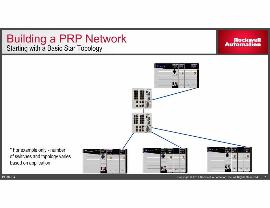
* For example only - number
of switches and topology varies
based on application
Building a PRP NetworkStarting with a Basic Star Topology

PUBLIC Copyright © 2017 Rockwell Automation, Inc. All Rights Reserved. 8
Redundant Ethernet Networks
Independent LANs
Independent Paths
Switches are not PRP aware
Redundancy is in the end nodes,
called, “Doubly Attached Nodes
(DANs)” attach
to both LANs
The DANs in this example are all
1756-EN2TP PRP modules
Any switch that supports 1506 byte
frames can be used
Building a PRP NetworkAdding Redundant Media and ControlLogix PRP Modules
LAN A LAN B
DAN DAN DAN
DAN
PUBLIC Copyright © 2017 Rockwell Automation, Inc. All Rights Reserved. 9
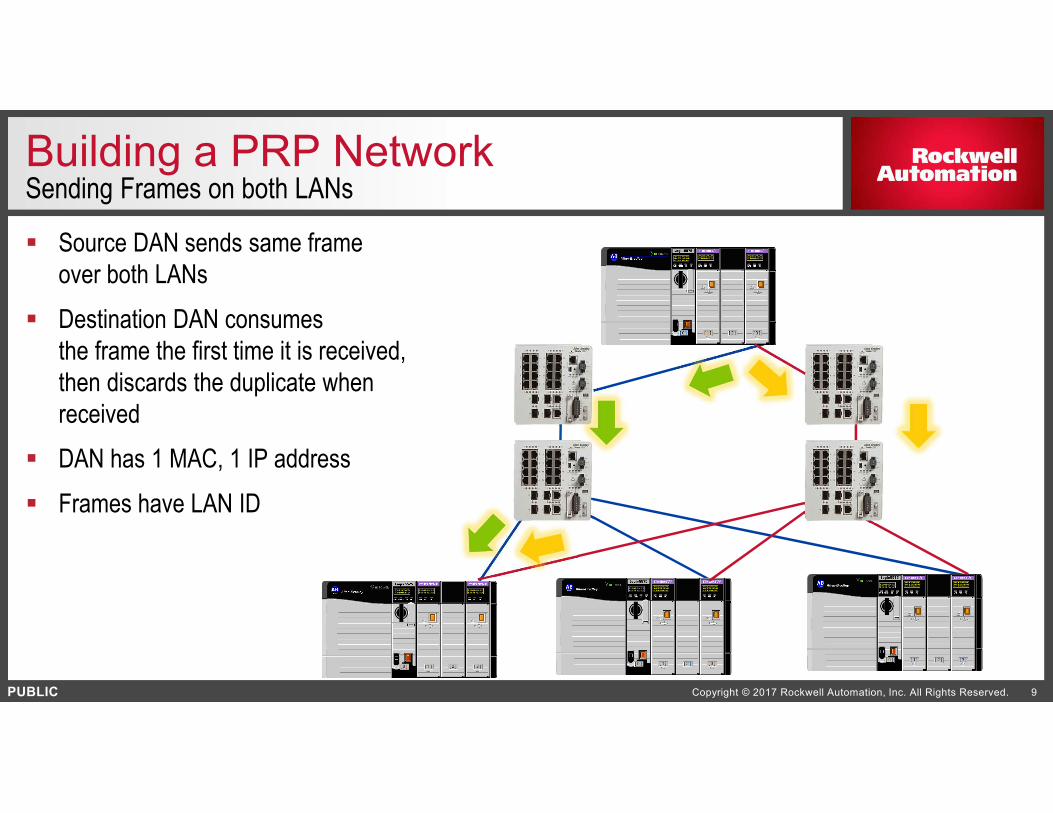
Building a PRP NetworkSending Frames on both LANs
Source DAN sends same frame
over both LANs
Destination DAN consumes
the frame the first time it is received,
then discards the duplicate when
received
DAN has 1 MAC, 1 IP address
Frames have LAN ID
PUBLIC Copyright © 2017 Rockwell Automation, Inc. All Rights Reserved. 10
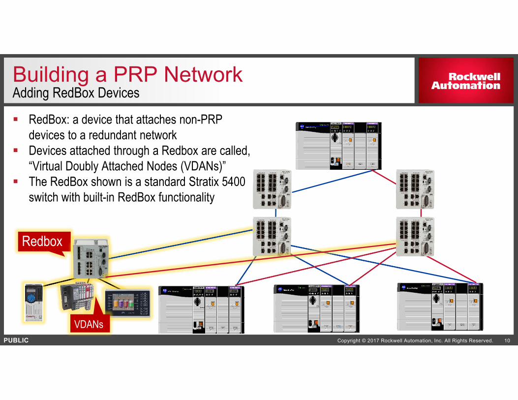
Building a PRP NetworkAdding RedBox Devices
RedBox: a device that attaches non-PRP
devices to a redundant network
Devices attached through a Redbox are called,
“Virtual Doubly Attached Nodes (VDANs)”
The RedBox shown is a standard Stratix 5400
switch with built-in RedBox functionality
Redbox
VDANs

PUBLIC Copyright © 2017 Rockwell Automation, Inc. All Rights Reserved. 11
Building a PRP NetworkAdding a Singly Attached Node
Non-PRP devices can be connected
to only one of the two LANs,
however, media redundancy is lost
Singly Attached Nodes (SANs)
can communicate only to other
devices on the LAN that they
are connected to
SANs are not PRP-aware
SAN
SAN

PUBLIC Copyright © 2017 Rockwell Automation, Inc. All Rights Reserved. 12
Building a PRP NetworkAdding ControlLogix Controller Redundancy
A ControlLogix Redundancy kit
including the 1756-EN2TP will not
be available at the same time as the
1756-EN2TP release.

PUBLIC Copyright © 2017 Rockwell Automation, Inc. All Rights Reserved. 13
PRP General FAQs
What are all the PRP products that Rockwell Automation currently offers and what are the limitations?
The 1756-EN2TP is currently available
The current Stratix® 5400 includes RedBox functionality
PRP support in FLEX 5000™ I/O is planned
Other products in the future will support PRP
A limitation is that, as of Aug 2017, there is not
a ControlLogix® Controller Redundancy firmware
kit that includes the 1756-EN2TP. This is forthcoming.

PUBLIC Copyright © 2017 Rockwell Automation, Inc. All Rights Reserved. 14
PRP General FAQs
How does a PRP network connect from the controls network (OT) up to the corporate network (IT)?
The PRP network at the controls level (OT) is connected to the corporate network (IT) level
through a RedBox
Do the network infrastructure switches (as opposed to the RedBoxes) need to have PRP protocol
built in?..
No. Any switch that supports the baby jumbo frame size of 1506 bytes will work in a PRP
network. The PRP protocol needs to be built into the end devices where the two LANs
connect (DANs or Redboxes). Rockwell Automation recommends the use of Stratix managed
switches because of their diagnostics, which allow for quicker troubleshooting and repair of
switches between the talking and listening nodes. If the switch is not capable of participating
in the diagnostics of the network, troubleshooting and repair can take longer.

PUBLIC Copyright © 2017 Rockwell Automation, Inc. All Rights Reserved. 15
PRP General FAQs
Can any switch be used as a RedBox?
Only switches specifically designed with Redbox functionality can function as a RedBox.
Can I use an ETAP as a RedBox?
At this time, ETAPs do not have PRP built in. An ETAP is used to put non-DLR devices onto a DLR ring.
Is it possible to add a non-PRP device to just one of the two LANs?
Yes, however only devices on the LAN that that device is attached to will be able to communicate with it. These are the SANs mentioned earlier.
Can I mix PRP devices from other vendors on the same network?
PRP is a standard protocol based on IEC-62439-3 but each vendor can implement it as they wish so Rockwell Automation cannot make any guarantees that mixing different vendor devices will work.

PUBLIC Copyright © 2017 Rockwell Automation, Inc. All Rights Reserved. 16
PRP General FAQs
What are the required features for the infrastructure switches that are part of the LANs?
The switch needs to be able to support baby jumbo size of 1506 bytes, to accommodate a full
size frame plus the PRP trailer.
What is the network healing time for a single fault on a PRP network?
Zero. A transmitting DAN duplicates the packet and sends it out on both LANs at the same
time. The receiving DAN gets both packets and simply discards the duplicate. There is no
concept of a healing time since there is no switchover from one LAN to the other. The module
evaluates incoming traffic on a packet by packet basis, always using the first of two packets
received.
How many IP addresses and MAC IDs does a PRP device have?
One IP address, one MAC ID
PUBLIC Copyright © 2017 Rockwell Automation, Inc. All Rights Reserved. 17
PRP General FAQs
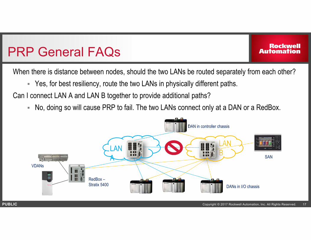
When there is distance between nodes, should the two LANs be routed separately from each other?
Yes, for best resiliency, route the two LANs in physically different paths.
Can I connect LAN A and LAN B together to provide additional paths?
No, doing so will cause PRP to fail. The two LANs connect only at a DAN or a RedBox.
LAN
A
LAN
BSAN
DANs in I/O chassis
VDANs
DAN in controller chassis
RedBox –
Stratix 5400

PUBLIC Copyright © 2017 Rockwell Automation, Inc. All Rights Reserved. 18
PRP General FAQs
Can any device be a SAN?
Any device can work as a SAN, however the benefits of redundancy are lost when a device is
not connected to both LANs.
It may be desirable to have redundant cabling but not a redundant switch.
Can both LANs be physically connected to a single infrastructure switch using VLANs in that
infrastructure switch? That way the network could still take advantage of redundant cabling
No, both LANs need to be on the same VLAN in PRP.
VLANs can be implemented in a PRP network
where each VLAN exists
on each LAN.
LAN A
(one VLAN)
LAN B
(another VLAN)
PUBLIC Copyright © 2017 Rockwell Automation, Inc. All Rights Reserved. 19
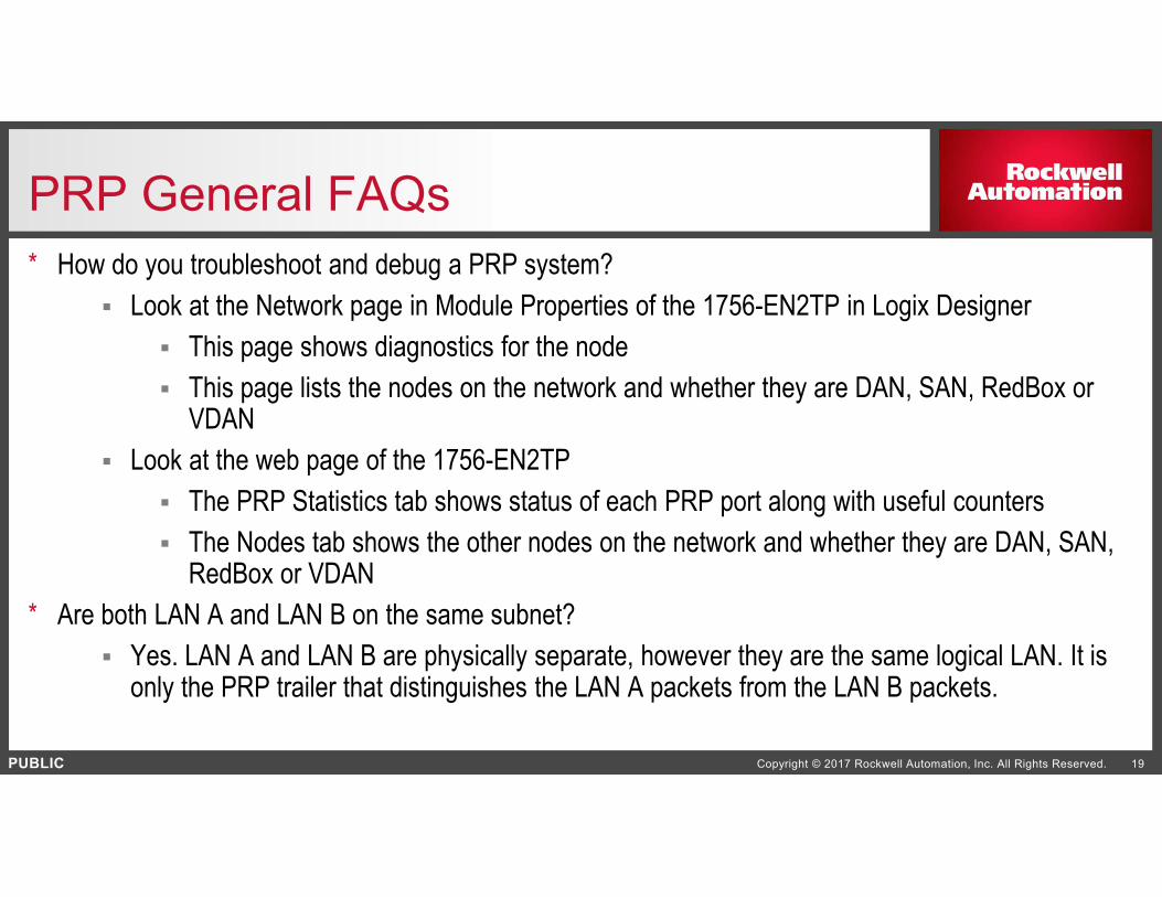
PRP General FAQs
* How do you troubleshoot and debug a PRP system?
Look at the Network page in Module Properties of the 1756-EN2TP in Logix Designer
This page shows diagnostics for the node
This page lists the nodes on the network and whether they are DAN, SAN, RedBox or VDAN
Look at the web page of the 1756-EN2TP
The PRP Statistics tab shows status of each PRP port along with useful counters
The Nodes tab shows the other nodes on the network and whether they are DAN, SAN, RedBox or VDAN
* Are both LAN A and LAN B on the same subnet?
Yes. LAN A and LAN B are physically separate, however they are the same logical LAN. It is only the PRP trailer that distinguishes the LAN A packets from the LAN B packets.
PUBLIC Copyright © 2017 Rockwell Automation, Inc. All Rights Reserved. 20
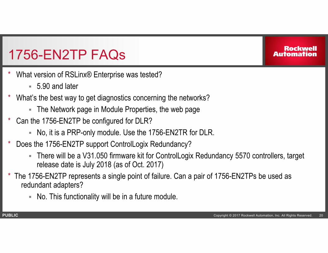
1756-EN2TP FAQs
* What version of RSLinx® Enterprise was tested?
5.90 and later
* What’s the best way to get diagnostics concerning the networks?
The Network page in Module Properties, the web page
* Can the 1756-EN2TP be configured for DLR?
No, it is a PRP-only module. Use the 1756-EN2TR for DLR.
* Does the 1756-EN2TP support ControlLogix Redundancy?
There will be a V31.050 firmware kit for ControlLogix Redundancy 5570 controllers, target release date is July 2018 (as of Oct. 2017)
* The 1756-EN2TP represents a single point of failure. Can a pair of 1756-EN2TPs be used asredundant adapters?
No. This functionality will be in a future module.

PUBLIC Copyright © 2017 Rockwell Automation, Inc. All Rights Reserved. 21
Stratix 5400 RedBox FAQs
* On the Stratix 5400 RedBox, on the VDAN side, can DLR rings be implemented?
Yes, all three rings can be implemented, no DLR rings are lost when Redbox functionality
is employed.
LAN
A
LAN
BVDANs in
DLR ring
(up to 3
rings)RedBox –
Stratix
5400

www.rockwellautomation.com
PUBLIC
Copyright © 2017 Rockwell Automation, Inc. All Rights Reserved. 22
Network RedundancyDevice Level Ring

PUBLIC Copyright © 2017 Rockwell Automation, Inc. All Rights Reserved. 23
Embedded Switch TechnologyDevice Level Ring (DLR) Overview
A DLR network is a single-fault tolerant
ring network intended for the
interconnection of automation devices:
Advantages include:
Simple installation
Fast recovery time

PUBLIC Copyright © 2017 Rockwell Automation, Inc. All Rights Reserved. 24
Stratix 5700 Managed Switch Differentiators
Includes integrated DLR connectivity
enabling the switch to act as a node or a
supervisor on the ring.
Offers consolidation of ring information for
a single point of management for retrieving
network machine-level diagnostics and
DLR status (in supervisor mode).
Provides redundant gateway capability
providing support for two switches on a
single ring connected together on the
network for increased resiliency.
Enables DHCP IP address assignment to
end devices on the DLR network for
simplified device replacement.

PUBLIC
Copyright © 2017 Rockwell Automation, Inc. All Rights Reserved. 25
FactoryTalk Network Manager Software
November 2017

PUBLIC Copyright © 2017 Rockwell Automation, Inc. All Rights Reserved. 26
Why Network Management Software?
Networks are critical to automation assets
Control, I/O, drives, HMI, etc.
Plants will experience significant network growth over the next several years
Plant floor staff tasked with network operations and maintenance
Increase visibility of automation assets on the network
Network health and monitoring in context of the plant floor assets
Simplify the troubleshooting process, quickly identify network root causes issues
More easily deploy, commission and maintain networks
Plant floor staff need an easy-to-use, intuitive tool not targeted at IT experts

PUBLIC Copyright © 2017 Rockwell Automation, Inc. All Rights Reserved. 27
FactoryTalk Network Manager Software
FactoryTalk® Network Manager software helps give you increased network visibility, real-time
troubleshooting and simplified configuration and deployment. Get insight into the performance of your
network operations by getting a closer look into your devices connected on the plant floor.
Network
VisibilityTroubleshooting
Configuration
and
Deployment

PUBLIC Copyright © 2017 Rockwell Automation, Inc. All Rights Reserved. 28
FactoryTalk Network Manager SoftwareFeatures and Benefits
• Discovery of plant floor assets
• Overall Topology and Device
Centric View
• CIP and PROFINET protocols
Network
VisibilityTroubleshooting
Configuration
and
Deployment
Name 131.200.174.141
IP Address 131.200.174.141
Product ID Industrial Managed Switch

PUBLIC Copyright © 2017 Rockwell Automation, Inc. All Rights Reserved. 29
Inventory View
Auto Discovery
EtherNet/IP
CIP/PROFINET
Routers/switches
End devices
Search
Link to end device
Export list
Network
VisibilityTroubleshooting
Configuration
and
Deployment

PUBLIC Copyright © 2017 Rockwell Automation, Inc. All Rights Reserved. 30
End Device View
Network
VisibilityTroubleshooting
Configuration
and
Deployment
CHASSIS LAYOUT
•Slot
•Name, Description
•Serial #
•Major, Minor Version
END DEVICE
•Device Overview
•Additional Details
PUBLIC Copyright © 2017 Rockwell Automation, Inc. All Rights Reserved. 31
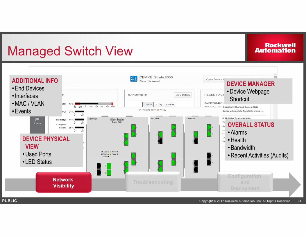
Managed Switch View
DEVICE MANAGER
•Device Webpage
Shortcut
OVERALL STATUS
•Alarms
•Health
•Bandwidth
•Recent Activities (Audits)
DEVICE PHYSICAL
VIEW
•Used Ports
•LED Status
ADDITIONAL INFO
•End Devices
• Interfaces
•MAC / VLAN
•Events
Network
VisibilityTroubleshooting
Configuration
and
Deployment
PUBLIC Copyright © 2017 Rockwell Automation, Inc. All Rights Reserved. 32
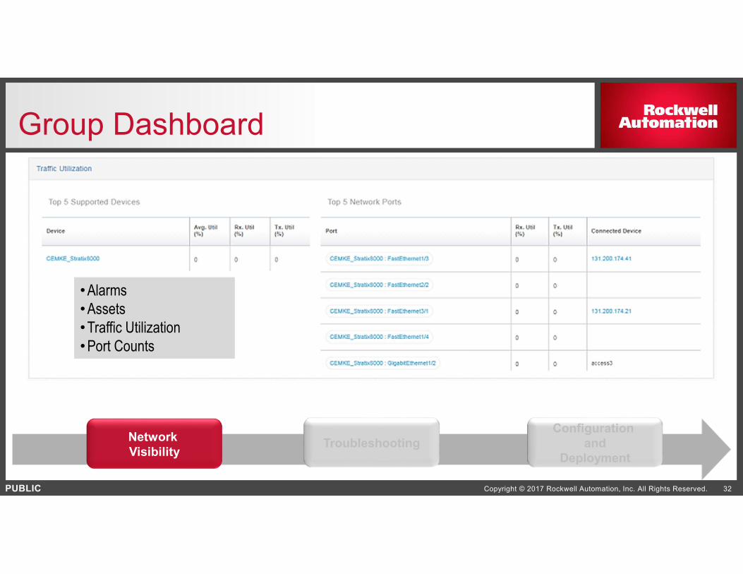
Group Dashboard
Network
VisibilityTroubleshooting
Configuration
and
Deployment
•Alarms
•Assets
•Traffic Utilization
•Port Counts

PUBLIC Copyright © 2017 Rockwell Automation, Inc. All Rights Reserved. 33
Alarm Overview
FILTER ALARMS
•Severity
•Active (New) or Closed
•Type
•Etc.
ALARM VIEW
•Severity, Time, Device, Message, etc.
•Affected Devices
•Assign to a user to resolve
•Stored in a database: Manage Retention Period
EXPORT ALARMS
•Export to CSV file
Network
VisibilityTroubleshooting
Configuration
and
Deployment
PUBLIC Copyright © 2017 Rockwell Automation, Inc. All Rights Reserved. 34
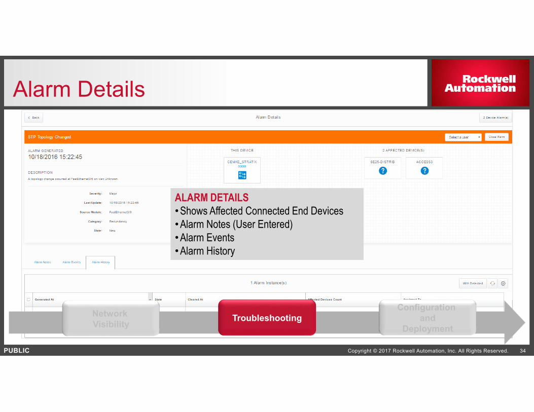
Alarm Details
ALARM DETAILS
•Shows Affected Connected End Devices
•Alarm Notes (User Entered)
•Alarm Events
•Alarm History
Network
VisibilityTroubleshooting
Configuration
and
Deployment

PUBLIC Copyright © 2017 Rockwell Automation, Inc. All Rights Reserved. 35
Software Audits
AUDIT DETAILS
•Network Management Software
•Time, User, Action, etc.
•Apply Filters
•Ability to Export to CSV file
Network
VisibilityTroubleshooting
Configuration
and
Deployment

PUBLIC Copyright © 2017 Rockwell Automation, Inc. All Rights Reserved. 36
Security
Three Default Roles
•Network Admin
•System Admin
•Operator
New User Rights
•Alarm Management
•Device Management
•Network Settings
•Role Based Access Control
•System Settings
•View Only
Network
VisibilityTroubleshooting
Configuration
and
Deployment

PUBLIC Copyright © 2017 Rockwell Automation, Inc. All Rights Reserved. 37
FactoryTalk Network Manager SoftwareFeatures and Benefits
• Discovery of plant floor assets
• Overall Topology and Device
Centric View
• CIP and PROFINET protocols
• Real-time capture of Alarms
and Events
• Historical retention for analysis
• Audit Trail
• Plug-n-Play
• Configuration Template
Network
VisibilityTroubleshooting
Configuration
and
Deployment
Name 131.200.174.141
IP Address 131.200.174.141
Product ID Industrial Managed Switch

PUBLIC Copyright © 2017 Rockwell Automation, Inc. All Rights Reserved. 38
Configuration and Deployment
Network
VisibilityTroubleshooting
Configuration
and
Deployment
Configuration Templates
•Push configuration to device based on template
Plug-n-Play (PnP)
•Upload existing configuration and apply variable substitution, attach it to a PnP profile
•Match PnP Profile (IP/Range, serial number, etc.)
•Dashboard, PnP status and metrics
PUBLIC Copyright © 2017 Rockwell Automation, Inc. All Rights Reserved. 39
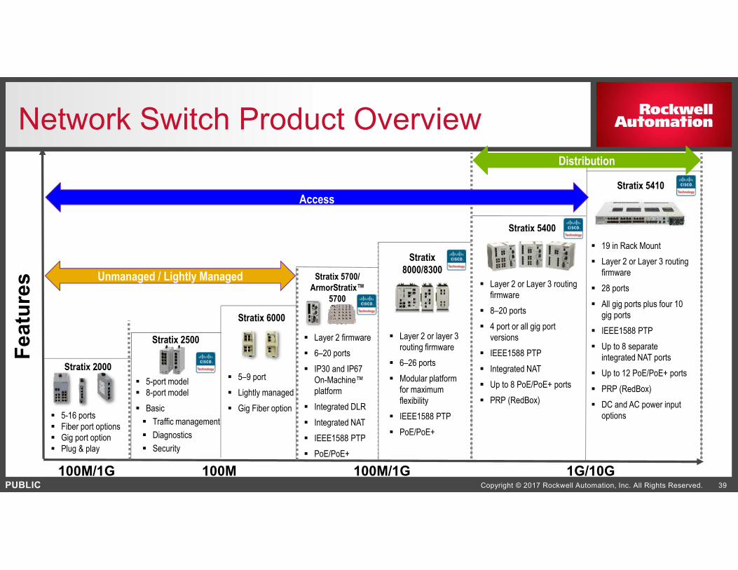
Network Switch Product Overview
Stratix
8000/8300
Stratix 5400
Stratix 5410
Layer 2 firmware
6–20 ports
IP30 and IP67
On-Machine™
platform
Integrated DLR
Integrated NAT
IEEE1588 PTP
PoE/PoE+
Layer 2 or layer 3
routing firmware
6–26 ports
Modular platform
for maximum
flexibility
IEEE1588 PTP
PoE/PoE+
Layer 2 or Layer 3 routing
firmware
8–20 ports
4 port or all gig port
versions
IEEE1588 PTP
Integrated NAT
Up to 8 PoE/PoE+ ports
PRP (RedBox)
Fe
atu
res
AccessAccess
DistributionDistribution
Stratix 2000
5-16 ports
Fiber port options
Gig port option
Plug & play
Unmanaged / Lightly Managed
Stratix 6000
5–9 port
Lightly managed
Gig Fiber option
19 in Rack Mount
Layer 2 or Layer 3 routing
firmware
28 ports
All gig ports plus four 10
gig ports
IEEE1588 PTP
Up to 8 separate
integrated NAT ports
Up to 12 PoE/PoE+ ports
PRP (RedBox)
DC and AC power input
options
Stratix 5700/
ArmorStratix™
5700
Stratix 2500
5-port model
8-port model
Basic
Traffic management
Diagnostics
Security
100M/1G 1G/10G100M/1G 100M
Copyright © 2016 Rockwell Automation, Inc. All Rights Reserved.
PUBLIC
PUBLIC
www.rockwellautomation.com
Stratix 5950 Security Appliance

PUBLIC Copyright © 2017 Rockwell Automation, Inc. All Rights Reserved. 41
Stratix 5950 Security Appliance
The Stratix® 5950 Security Appliance brings an industrially-hardened security product
to the networks and security infrastructure portfolio of products. The Stratix® 5950
Security Appliance helps provide increased visibility and control with Deep Packet
Inspection (DPI) capabilities to help protect your assets down to the machine level.

PUBLIC Copyright © 2017 Rockwell Automation, Inc. All Rights Reserved. 42
Stratix 5950 Security Appliance Differentiators
DIN rail mount offers increased design flexibility
Industrially-hardened for high temperature demands (-40°C to 60°C)
Deep Packet Inspection technology provides the visibility and controls needed for implementing policies around access, applications and
protocols on the plant floor
Maintain your protection against
threats and control your assets with
subscription based licensing
Cisco ASA firewall and FirePOWER technology
provide prevention services to identify, log or block potentially
malicious traffic
SFP slots enable flexibility by allowing
multiple options for fiber connectivity
PUBLIC Copyright © 2017 Rockwell Automation, Inc. All Rights Reserved. 43
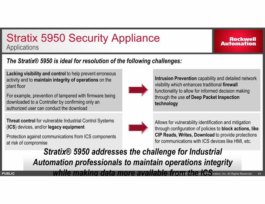
Stratix 5950 Security ApplianceApplications
Lacking visibility and control to help prevent erroneous
activity and to maintain integrity of operations on the
plant floor
For example, prevention of tampered with firmware being
downloaded to a Controller by confirming only an
authorized user can conduct the download
Intrusion Prevention capability and detailed network
visibility which enhances traditional firewall
functionality to allow for informed decision making
through the use of Deep Packet Inspection
technology
Threat control for vulnerable Industrial Control Systems
(ICS) devices, and/or legacy equipment
Protection against communications from ICS components
at risk of compromise
Allows for vulnerability identification and mitigation
through configuration of policies to block actions, like
CIP Reads, Writes, Download to provide protections
for communications with ICS devices like HMI, etc.
The Stratix® 5950 is ideal for resolution of the following challenges:
Stratix® 5950 addresses the challenge for Industrial
Automation professionals to maintain operations integrity
while making data more available from the ICS

PUBLIC Copyright © 2017 Rockwell Automation, Inc. All Rights Reserved. 44
Firewalls and Deep Packet Inspection
Typical IT firewalls are capable of inspecting
Source or Destination MAC or IP Address
Source or Destination TCP or UDP Ports, or
Protocol elements of a packet
Deep Packet Inspection extends upon these firewalls’ capabilities
Provides granular protection per protocol (ex. CIP, Modbus, DNP3) in the Industrial Zone
Giving the visibility and control to help prevent erroneous or malicious activity down to the Cell / Area zone level
Intrusion Prevention uses DPI
What you want to do after you have inspected the packet?
1.) After inspecting the packet using DPI, achieve granular control through security rules that act on matched network traffic
2.) Do we allow this application or command, or is this a known threat?

PUBLIC Copyright © 2017 Rockwell Automation, Inc. All Rights Reserved. 45
IPS – IDS – Firewall Comparison
45
• Inspects traffic flowing through a network and is capable of blocking what it determines to be maliciousIPS
• Similar to IPS but does not affect traffic flows in any way; only logs or alerts on malicious trafficIDS
• Helps prevent or allow traffic between interfaces based on policies
• Often use network address translation (NAT) to isolate private network addresses from public ones
• May inspect traffic for conformance with proper protocol behavior
Firewall

PUBLIC Copyright © 2017 Rockwell Automation, Inc. All Rights Reserved. 46
Stratix 5950 Subscription License
Operation ControlOperations are mapped to DPI Patterns and
Sequences
Application ControlApplications are identified using underlying
Protocol and App-level Info.
Network-Level FilteringEndpoints are passively identified and
filtered using IP and MAC addresses.
Threat MitigationThreats are mapped to DPI Patterns and
Sequences
Zero-Day ProtectionTerm Based Service for Threat and
Application Control Updates
Term-based Live Threat and Application Control Security Services

PUBLIC Copyright © 2017 Rockwell Automation, Inc. All Rights Reserved. 47
Compliant in IEC 62443 ArchitectureSecurity Zones, Conduits and Barrier Devices
Zone 2Zone 2Zone 1Zone 1
In Transparent Mode:
The security device acts as a
barrier device between Cell/Area
Zones to allow segmentation of
control systems to enable the
implementation of an
ISA99/IEC62443-compliant
network architecture.
Security Zones
Barrier Devices
PUBLIC Copyright © 2017 Rockwell Automation, Inc. All Rights Reserved. 48
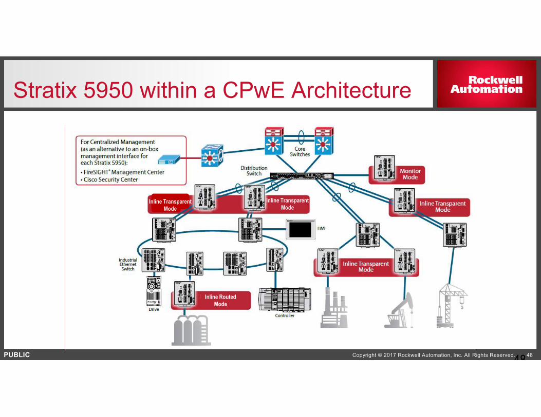
Stratix 5950 within a CPwE Architecture
48
Inline Transparent
Mode
Inline Transparent
Mode
Inline Routed
Mode
PUBLIC Copyright © 2017 Rockwell Automation, Inc. All Rights Reserved. 49
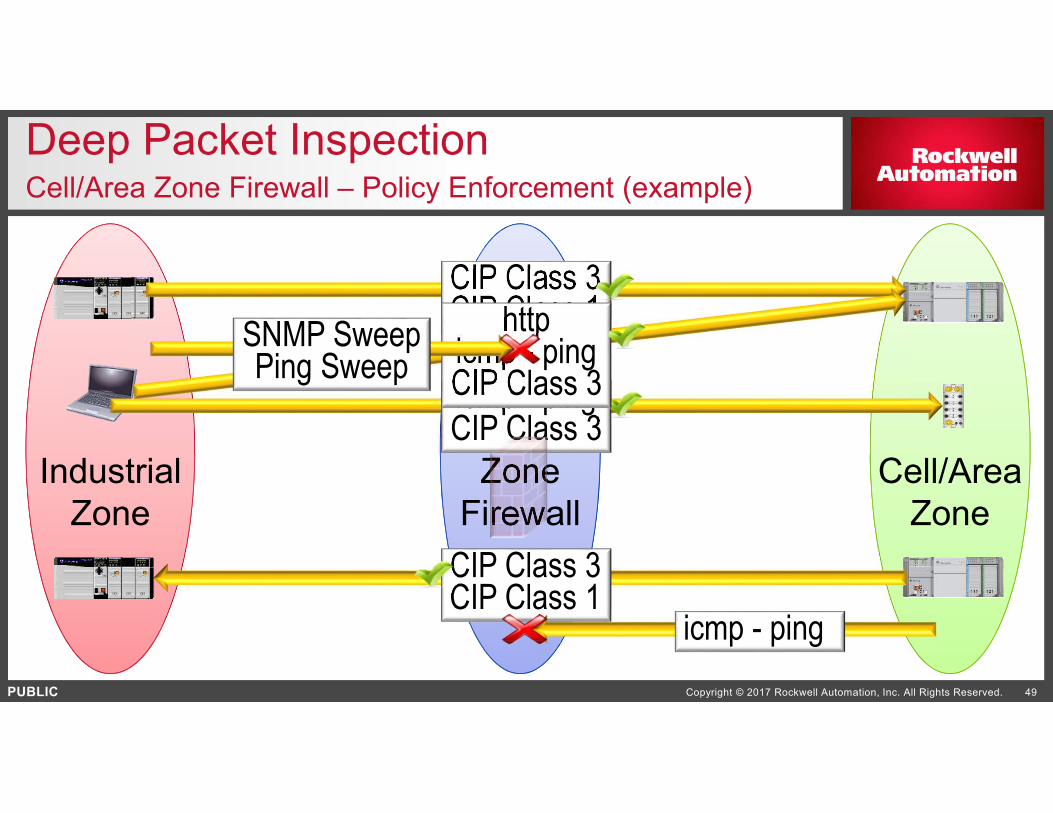
Zone
Firewall
Deep Packet InspectionCell/Area Zone Firewall – Policy Enforcement (example)
Industrial
Zone
Cell/Area
Zone
CIP Class 3CIP Class 1
icmp - pingCIP Class 3
CIP Class 3CIP Class 1httpicmp - pingCIP Class 3
SNMP SweepPing Sweep
icmp - ping