1794-in106d-en-e flex i/o dc input, output, and input ... instructions flex i/o dc input, output,...
TRANSCRIPT
Installation Instructions
FLEX I/O DC Input, Output, and Input/Output Analog ModulesCatalog Numbers 1794-IE12, 1794-OE12, and 1794-IE8XOE4
Table of Contents
Topic Page
Important User Information 2
Environment and Enclosure 3
Prevent Electrostatic Discharge 3
North American Hazardous Location Approval 5
Install Your Analog Input/Output Module 6
Connect Wiring 6
Configuring Your Module 11
Data Table – 1794-IE12 11
Data Table – 1794-OE12 13
Data Table – 1794-IE8XOE4 14
Specifications 15
2 FLEX I/O DC Input, Output, and Input/Output Analog Modules
Important User Information
Solid state equipment has operational characteristics differing from those of electromechanical equipment Safety Guidelines for the Application, Installation and Maintenance of Solid State Controls (Publication SGI-1.1 available from your local Rockwell Automation sales office or online at http://literature.rockwellautomation.com) describes some important differences between solid state equipment and hard-wired electromechanical devices. Because of this difference, and also because of the wide variety of uses for solid state equipment, all persons responsible for applying this equipment must satisfy themselves that each intended application of this equipment is acceptable.
In no event will Rockwell Automation, Inc. be responsible or liable for indirect or consequential damages resulting from the use or application of this equipment.
The examples and diagrams in this manual are included solely for illustrative purposes. Because of the many variables and requirements associated with any particular installation, Rockwell Automation, Inc. cannot assume responsibility or liability for actual use based on the examples and diagrams.
No patent liability is assumed by Rockwell Automation, Inc., with respect to use of information, circuits, equipment, or software described in this manual.
Reproduction of the contents of this manual, in whole or in part, without written permission of Rockwell Automation, Inc., is prohibited.
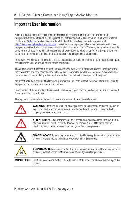
Throughout this manual we use notes to make you aware of safety considerations.
WARNING: Identifies information about practices or circumstances that can cause an explosion in a hazardous environment, which may lead to personal injury or death, property damage, or economic loss.
ATTENTION: Identifies information about practices or circumstances that can lead to personal injury or death, property damage, or economic loss. Attentions help you: identify a hazard, avoid a hazard, and recognize the consequences.
SHOCK HAZARD: Labels may be located on or inside the equipment (for example, drive or motor) to alert people that dangerous voltage may be present.
BURN HAZARD: Labels may be located on or inside the equipment (for example, drive or motor) to alert people that surfaces may be dangerous temperatures.
IMPORTANT Identifies information that is critical for successful application and understanding of the product.
Publication 1794-IN106D-EN-E - January 2014
FLEX I/O DC Input, Output, and Input/Output Analog Modules 3
Environment and Enclosure
Prevent Electrostatic Discharge
This equipment is intended for use in a Pollution Degree 2 industrial environment, in overvoltage Category II applications (as defined in IEC publication 60664-1), at altitudes up to 2000 meters without derating.
This equipment is considered Group 1, Class A industrial equipment according to IEC/CISPR Publication 11. Without appropriate precautions, there may be potential difficulties ensuring electromagnetic compatibility in other environments due to conducted as well as radiated disturbance.
This equipment is supplied as open-type equipment. It must be mounted within an enclosure that is suitably designed for those specific environmental conditions that will be present and appropriately designed to prevent personal injury resulting from accessibility to live parts. The interior of the enclosure must be accessible only by the use of a tool. Subsequent sections of this publication may contain additional information regarding specific enclosure type ratings that are required to comply with certain product safety certifications.
See NEMA Standards publication 250 and IEC publication 60529, as applicable, for explanations of the degrees of protection provided by different types of enclosure. Also, see the appropriate sections in this publication, as well as Industrial Automation Wiring and Grounding Guidelines, Allen-Bradley publication 1770-IN041, for additional installation requirements pertaining to this equipment.
ATTENTION: This equipment is sensitive to electrostatic discharge, which can cause internal damage and affect normal operation. Follow these guidelines when you handle this equipment:• Touch a grounded object to discharge potential static.• Wear an approved grounding wriststrap.• Do not touch connectors or pins on component boards.• Do not touch circuit components inside the equipment.• Use a static-safe workstation, if available.• Store the equipment in appropriate static-safe packaging when not in use.
Publication 1794-IN106D-EN-E - January 2014
4 FLEX I/O DC Input, Output, and Input/Output Analog Modules
WARNING: If you insert or remove the module while backplane power is on, an electrical arc can occur. This could cause an explosion in hazardous location installations. Be sure that power is removed or the area is nonhazardous before proceeding.
WARNING: If you connect or disconnect wiring while the field side power is on, an electrical arc can occur. This could cause an explosion in hazardous location installations. Be sure that power is removed or the area is nonhazardous before proceeding.
ATTENTION: This product is grounded through the DIN rail to chassis ground. Use zinc plated yellow-chromate steel DIN rail to assure proper grounding. The use of other DIN rail materials (such as aluminum or plastic) that can corrode, oxidize, or are poor conductors, can result in improper or intermittent grounding.
ATTENTION: To comply with the CE Low Voltage Directive (LVD), all connections to this equipment must be powered from a source compliant with the following:
Safety Extra Low Voltage (SELV) or Protected Extra Low Voltage (PELV).
Publication 1794-IN106D-EN-E - January 2014
FLEX I/O DC Input, Output, and Input/Output Analog Modules 5
North American Hazardous Location Approval The following information applies when operating this equipment in hazardous locations:
Informations sur l’utilisation de cet équipement en environnements dangereux:
Products marked CL I, DIV 2, GP A, B, C, D are suitable for use in Class I Division 2 Groups A, B, C, D, hazardous locations and nonhazardous locations only. Each product is supplied with markings on the rating nameplate indicating the hazardous location temperature code. When combining products within a system, the most adverse temperature code (lowest “T” number) may be used to help determine the overall temperature code of the system. Combinations of equipment in your system are subject to investigation by the local Authority Having Jurisdiction at the time of installation.
Les produits marqués CL I, DIV 2, GP A, B, C, D ne conviennent qu’à une utilisation en environnements de Classe I Division 2 Groupes A, B, C, D dangereux et non dangereux. Chaque produit est livré avec des marquages sur sa plaque d’identification qui indiquent le code de température pour les environnements dangereux. Lorsque plusieurs produits sont combinés dans un système, le code de température le plus défavorable (code de température le plus faible) peut être utilisé pour déterminer le code de température global du système. Les combinaisons d’équipements dans le système sont sujettes à inspection par les autorités locales qualifiées au moment de l’installation.
WARNING: EXPLOSION HAZARD• Do not disconnect equipment
unless power has been removed or the area is known to be nonhazardous.
• Do not disconnect connections to this equipment unless power has been removed or the area is known to be nonhazardous. Secure any external connections that mate to this equipment by using screws, sliding latches, threaded connectors, or other means provided with this product.
• Substitution of components may impair suitability for Class I, Division 2.
• If this product contains batteries, they must only be changed in an area known to be nonhazardous.
WARNING: RISQUE D’EXPLOSION• Couper le courant ou s’assurer que
l’environnement est classé non dangereux avant de débrancher l'équipement.
• Couper le courant ou s'assurer que l’environnement est classé non dangereux avant de débrancher les connecteurs. Fixer tous les connecteurs externes reliés à cet équipement à l'aide de vis, loquets coulissants, connecteurs filetés ou autres moyens fournis avec ce produit.
• La substitution de composants peut rendre cet équipement inadapté à une utilisation en environnement de Classe I, Division 2.
• S’assurer que l’environnement est classé non dangereux avant de changer les piles.
Publication 1794-IN106D-EN-E - January 2014
6 FLEX I/O DC Input, Output, and Input/Output Analog Modules
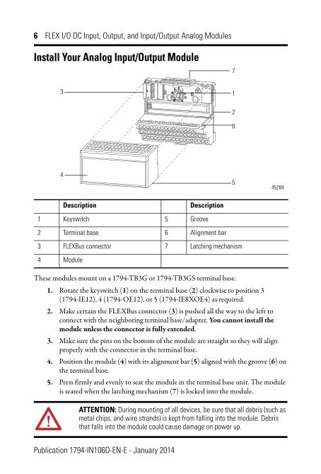
Install Your Analog Input/Output Module
These modules mount on a 1794-TB3G or 1794-TB3GS terminal base.
1. Rotate the keyswitch (1) on the terminal base (2) clockwise to position 3 (1794-IE12), 4 (1794-OE12), or 5 (1794-IE8XOE4) as required.
2. Make certain the FLEXBus connector (3) is pushed all the way to the left to connect with the neighboring terminal base/adapter. You cannot install the module unless the connector is fully extended.
3. Make sure the pins on the bottom of the module are straight so they will align properly with the connector in the terminal base.
4. Position the module (4) with its alignment bar (5) aligned with the groove (6) on the terminal base.
5. Press firmly and evenly to seat the module in the terminal base unit. The module is seated when the latching mechanism (7) is locked into the module.
Description Description
1 Keyswitch 5 Groove
2 Terminal base 6 Alignment bar
3 FLEXBus connector 7 Latching mechanism
4 Module
ATTENTION: During mounting of all devices, be sure that all debris (such as metal chips, and wire strands) is kept from falling into the module. Debris that falls into the module could cause damage on power up.
3
7
1
6
54
2
45284
Publication 1794-IN106D-EN-E - January 2014
FLEX I/O DC Input, Output, and Input/Output Analog Modules 7
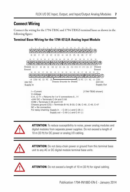
Connect WiringConnect the wiring for the 1794-TB3G and 1794-TB3GS terminal bases as shown in the following figure:
Terminal Base Wiring for the 1794-IE12/A Analog Input Module
ATTENTION: To reduce susceptibility to noise, power analog modules and digital modules from separate power supplies. Do not exceed a length of 10 m (33 ft) for DC power or analog I/O cabling.
ATTENTION: Do not daisy-chain power or ground from this terminal base unit to any AC or DC digital module terminal base units.
ATTENTION: Do not exceed a length of 10 m (33 ft) for signal cabling.
I = Current [1794-TB3G shown]V=VoltageC-0...C-11 = Returns for I or V connections 0...11+24V DC = Terminals C-34 and C-50COM = Terminals C-35 and C-51Chassis ground (CG) = Terminals B-16, B-33, C-38, C-40...C-45, C-47NC = No connectionFor daisy-chaining: Supply in – C-34 (+) and C-35 (-) Supply out – C-50 (+) and C-51 (-)
24V DCSupply In
24V DCSupply Out
17 18 19 20 21 22 23 24 25 26 27 28 29 30 31 32 33
0 1 2 3 4 5 6 7 8 9 10 11 12 13 14 15
16
35 36 37 38 39 40 41 42 43 44 45 46 47 48 49 50 5134
ChassisGround
ChassisGround
+V COM +V COMChassis Grounds for Shields
A
B
CNC
I0 I1 I2 I3 I4 I5 I6 I7
I8 I9 I10 I11
V0 V1 V2 V3 V4 V5 V6 V7
V8 V9 V10 V11C0 C1 C2 C3 C4 C5 C6 C7
C8 C9 C10 C11NC NC NC
Publication 1794-IN106D-EN-E - January 2014
8 FLEX I/O DC Input, Output, and Input/Output Analog Modules
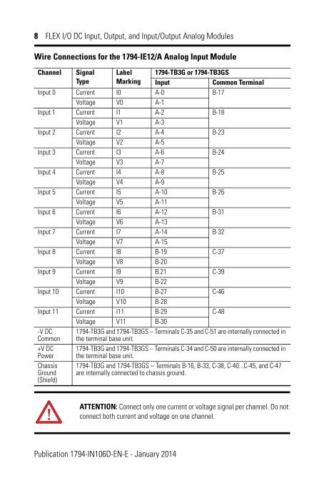
Wire Connections for the 1794-IE12/A Analog Input Module
Channel Signal Type
Label Marking
1794-TB3G or 1794-TB3GSInput Common Terminal
Input 0 Current I0 A-0 B-17Voltage V0 A-1
Input 1 Current I1 A-2 B-18Voltage V1 A-3
Input 2 Current I2 A-4 B-23Voltage V2 A-5
Input 3 Current I3 A-6 B-24Voltage V3 A-7
Input 4 Current I4 A-8 B-25Voltage V4 A-9
Input 5 Current I5 A-10 B-26Voltage V5 A-11
Input 6 Current I6 A-12 B-31Voltage V6 A-13
Input 7 Current I7 A-14 B-32Voltage V7 A-15
Input 8 Current I8 B-19 C-37Voltage V8 B-20
Input 9 Current I9 B.21 C-39Voltage V9 B-22
Input 10 Current I10 B-27 C-46Voltage V10 B-28
Input 11 Current I11 B-29 C-48Voltage V11 B-30
-V DC Common
1794-TB3G and 1794-TB3GS – Terminals C-35 and C-51 are internally connected in the terminal base unit.
+V DC Power
1794-TB3G and 1794-TB3GS – Terminals C-34 and C-50 are internally connected in the terminal base unit.
Chassis Ground (Shield)
1794-TB3G and 1794-TB3GS – Terminals B-16, B-33, C-38, C-40...C-45, and C-47 are internally connected to chassis ground.
ATTENTION: Connect only one current or voltage signal per channel. Do not connect both current and voltage on one channel.
Publication 1794-IN106D-EN-E - January 2014
FLEX I/O DC Input, Output, and Input/Output Analog Modules 9
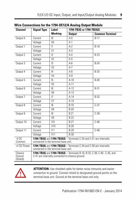
Wire Connections for the 1794-OE12/A Analog Output ModuleChannel Signal Type Label
Marking1794-TB3G or 1794-TB3GSOutput Common Terminal
Output 0 Current I0 A-0 B-17Voltage V0 A-1
Output 1 Current I1 A-2 B-18Voltage V1 A-3
Output 2 Current I2 A-4 B-23Voltage V2 A-5
Output 3 Current I3 A-6 B-24Voltage V3 A-7
Output 4 Current I4 A-8 B-25Voltage V4 A-9
Output 5 Current I5 A-10 B-26Voltage V5 A-11
Output 6 Current I6 A-12 B-31Voltage V6 A-13
Output 7 Current I7 A-14 B-32Voltage V7 A-15
Output 8 Current I8 B-19 C-37Voltage V8 B-20
Output 9 Current I9 B.21 C-39Voltage V9 B-22
Output 10 Current I10 B-27 C-46Voltage V10 B-28
Output 11 Current I11 B-29 C-48Voltage V11 B-30
-V DC Common
1794-TB3G and 1794-TB3GS – Terminals C-35 and C-51 are internally connected in the terminal base unit.
+V DC Power 1794-TB3G and 1794-TB3GS – Terminals C-34 and C-50 are internally connected in the terminal base unit.
Chassis Ground (Shield)
1794-TB3G and 1794-TB3GS – Terminals B-16, B-33, C-38, C-40...C-45, and C-47 are internally connected to chassis ground.
ATTENTION: Use shielded cable for better noise immunity and easier connection to ground. Connect shield to designated ground points on the terminal base unit. Ground at the terminal base unit only.
Publication 1794-IN106D-EN-E - January 2014
10 FLEX I/O DC Input, Output, and Input/Output Analog Modules
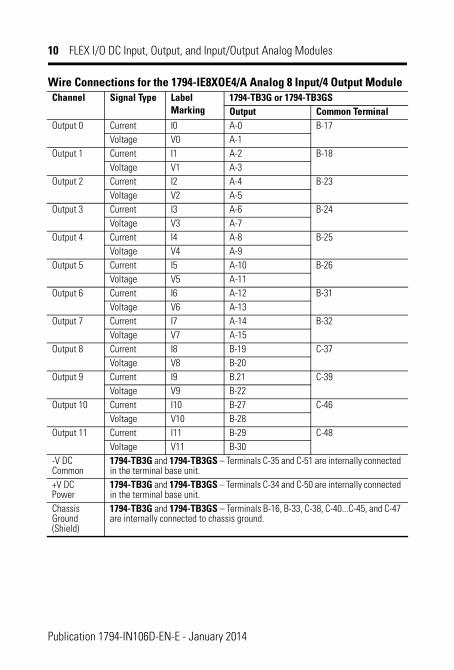
Wire Connections for the 1794-IE8XOE4/A Analog 8 Input/4 Output ModuleChannel Signal Type Label
Marking1794-TB3G or 1794-TB3GSOutput Common Terminal
Output 0 Current I0 A-0 B-17Voltage V0 A-1
Output 1 Current I1 A-2 B-18Voltage V1 A-3
Output 2 Current I2 A-4 B-23Voltage V2 A-5
Output 3 Current I3 A-6 B-24Voltage V3 A-7
Output 4 Current I4 A-8 B-25Voltage V4 A-9
Output 5 Current I5 A-10 B-26Voltage V5 A-11
Output 6 Current I6 A-12 B-31Voltage V6 A-13
Output 7 Current I7 A-14 B-32Voltage V7 A-15
Output 8 Current I8 B-19 C-37Voltage V8 B-20
Output 9 Current I9 B.21 C-39Voltage V9 B-22
Output 10 Current I10 B-27 C-46Voltage V10 B-28
Output 11 Current I11 B-29 C-48Voltage V11 B-30
-V DC Common
1794-TB3G and 1794-TB3GS – Terminals C-35 and C-51 are internally connected in the terminal base unit.
+V DC Power
1794-TB3G and 1794-TB3GS – Terminals C-34 and C-50 are internally connected in the terminal base unit.
Chassis Ground (Shield)
1794-TB3G and 1794-TB3GS – Terminals B-16, B-33, C-38, C-40...C-45, and C-47 are internally connected to chassis ground.
Publication 1794-IN106D-EN-E - January 2014
FLEX I/O DC Input, Output, and Input/Output Analog Modules 11
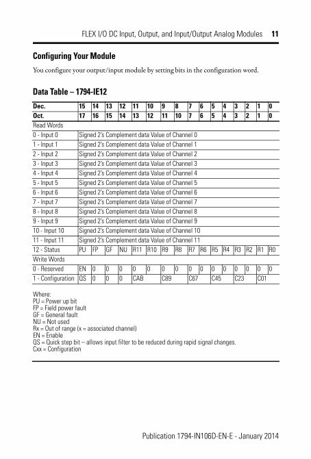
Configuring Your ModuleYou configure your output/input module by setting bits in the configuration word.
Data Table – 1794-IE12Dec. 15 14 13 12 11 10 9 8 7 6 5 4 3 2 1 0Oct. 17 16 15 14 13 12 11 10 7 6 5 4 3 2 1 0Read Words0 - Input 0 Signed 2’s Complement data Value of Channel 01 - Input 1 Signed 2’s Complement data Value of Channel 12 - Input 2 Signed 2’s Complement data Value of Channel 23 - Input 3 Signed 2’s Complement data Value of Channel 34 - Input 4 Signed 2’s Complement data Value of Channel 45 - Input 5 Signed 2’s Complement data Value of Channel 56 - Input 6 Signed 2’s Complement data Value of Channel 67 - Input 7 Signed 2’s Complement data Value of Channel 78 - Input 8 Signed 2’s Complement data Value of Channel 89 - Input 9 Signed 2’s Complement data Value of Channel 910 - Input 10 Signed 2’s Complement data Value of Channel 1011 - Input 11 Signed 2’s Complement data Value of Channel 1112 - Status PU FP GF NU R11 R10 R9 R8 R7 R6 R5 R4 R3 R2 R1 R0Write Words0 - Reserved EN 0 0 0 0 0 0 0 0 0 0 0 0 0 0 01 - Configuration QS 0 0 0 CAB C89 C67 C45 C23 C01
Where:PU = Power up bit FP = Field power fault GF = General fault NU = Not used Rx = Out of range (x = associated channel) EN = Enable QS = Quick step bit – allows input filter to be reduced during rapid signal changes.Cxx = Configuration
Publication 1794-IN106D-EN-E - January 2014
12 FLEX I/O DC Input, Output, and Input/Output Analog Modules
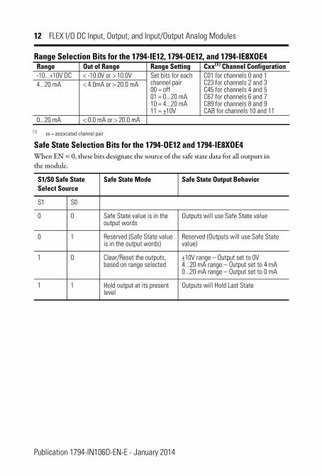
Range Selection Bits for the 1794-IE12, 1794-OE12, and 1794-IE8XOE4
Safe State Selection Bits for the 1794-OE12 and 1794-IE8XOE4When EN = 0, these bits designate the source of the safe state data for all outputs in the module.
Range Out of Range Range Setting Cxx(1) Channel Configuration
(1) xx = associated channel pair
-10...+10V DC < -10.0V or > 10.0V Set bits for each channel pair 00 = off 01 = 0...20 mA 10 = 4...20 mA 11 = +10V
C01 for channels 0 and 1 C23 for channels 2 and 3 C45 for channels 4 and 5 C67 for channels 6 and 7 C89 for channels 8 and 9 CAB for channels 10 and 11
4...20 mA < 4.0mA or > 20.0 mA
0...20 mA < 0.0 mA or > 20.0 mA
S1/S0 Safe State Select Source
Safe State Mode Safe State Output Behavior
S1 S0
0 0 Safe State value is in the output words
Outputs will use Safe State value
0 1 Reserved (Safe State value is in the output words)
Reserved (Outputs will use Safe State value)
1 0 Clear/Reset the outputs, based on range selected
+10V range – Output set to 0V 4...20 mA range – Output set to 4 mA 0...20 mA range – Output set to 0 mA
1 1 Hold output at its present level
Outputs will Hold Last State
Publication 1794-IN106D-EN-E - January 2014
FLEX I/O DC Input, Output, and Input/Output Analog Modules 13
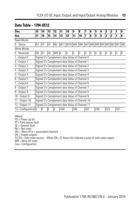
Data Table – 1794-OE12Dec. 15 14 13 12 11 10 9 8 7 6 5 4 3 2 1 0Oct. 17 16 15 14 13 12 11 10 7 6 5 4 3 2 1 0Read Words0 - Status PU FP GF NU W11 W10 W9 W8 W7 W6 W5 W4 W3 W2 W1 W0Write Words0 - Reserved EN S1 S0 WR 0 0 0 0 0 0 0 0 0 0 0 01 - Output 0 Signed 2’s Complement data Value of Channel 02 - Output 1 Signed 2’s Complement data Value of Channel 13 - Output 2 Signed 2’s Complement data Value of Channel 24 - Output 3 Signed 2’s Complement data Value of Channel 35 - Output 4 Signed 2’s Complement data Value of Channel 46 - Output 5 Signed 2’s Complement data Value of Channel 57 - Output 6 Signed 2’s Complement data Value of Channel 68 - Output 7 Signed 2’s Complement data Value of Channel 79 - Output 8 Signed 2’s Complement data Value of Channel 810 - Output 9 Signed 2’s Complement data Value of Channel 911 - Output 10 Signed 2’s Complement data Value of Channel 1012 - Output 11 Signed 2’s Complement data Value of Channel 1113 - Configuration 0 0 0 0 CAB C89 C67 C45 C23 C01
Where:PU = Power up bit FP = Field power fault GF = General fault NU = Not used Wx = Wire off (x = associated channel) EN = Enable outputs S1/S0 = Safe state source – When EN = 0, these bits indicate source of safe state output. WR = Wire-off reset Cxx = Configuration
Publication 1794-IN106D-EN-E - January 2014
14 FLEX I/O DC Input, Output, and Input/Output Analog Modules
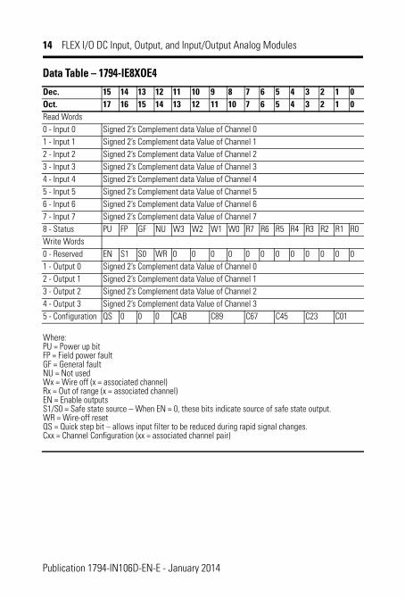
Data Table – 1794-IE8XOE4Dec. 15 14 13 12 11 10 9 8 7 6 5 4 3 2 1 0Oct. 17 16 15 14 13 12 11 10 7 6 5 4 3 2 1 0Read Words0 - Input 0 Signed 2’s Complement data Value of Channel 01 - Input 1 Signed 2’s Complement data Value of Channel 12 - Input 2 Signed 2’s Complement data Value of Channel 23 - Input 3 Signed 2’s Complement data Value of Channel 34 - Input 4 Signed 2’s Complement data Value of Channel 45 - Input 5 Signed 2’s Complement data Value of Channel 56 - Input 6 Signed 2’s Complement data Value of Channel 67 - Input 7 Signed 2’s Complement data Value of Channel 78 - Status PU FP GF NU W3 W2 W1 W0 R7 R6 R5 R4 R3 R2 R1 R0Write Words0 - Reserved EN S1 S0 WR 0 0 0 0 0 0 0 0 0 0 0 01 - Output 0 Signed 2’s Complement data Value of Channel 02 - Output 1 Signed 2’s Complement data Value of Channel 13 - Output 2 Signed 2’s Complement data Value of Channel 24 - Output 3 Signed 2’s Complement data Value of Channel 35 - Configuration QS 0 0 0 CAB C89 C67 C45 C23 C01
Where: PU = Power up bitFP = Field power faultGF = General faultNU = Not usedWx = Wire off (x = associated channel)Rx = Out of range (x = associated channel)EN = Enable outputsS1/S0 = Safe state source – When EN = 0, these bits indicate source of safe state output.WR = Wire-off resetQS = Quick step bit – allows input filter to be reduced during rapid signal changes.Cxx = Channel Configuration (xx = associated channel pair)
Publication 1794-IN106D-EN-E - January 2014
FLEX I/O DC Input, Output, and Input/Output Analog Modules 15
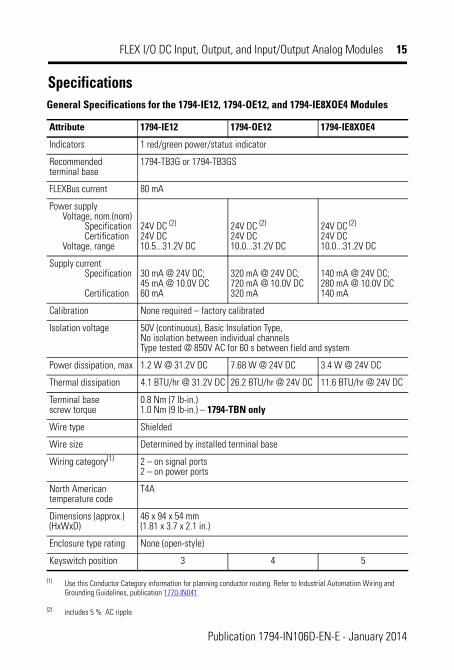
SpecificationsGeneral Specifications for the 1794-IE12, 1794-OE12, and 1794-IE8XOE4 Modules
Attribute 1794-IE12 1794-OE12 1794-IE8XOE4
Indicators 1 red/green power/status indicator
Recommended terminal base
1794-TB3G or 1794-TB3GS
FLEXBus current 80 mA
Power supply Voltage, nom.(nom) Specification Certification Voltage, range
24V DC (2) 24V DC 10.5...31.2V DC
(2) includes 5 % AC ripple
24V DC (2)
24V DC 10.0...31.2V DC
24V DC (2)
24V DC 10.0...31.2V DC
Supply current Specification Certification
30 mA @ 24V DC; 45 mA @ 10.0V DC 60 mA
320 mA @ 24V DC; 720 mA @ 10.0V DC 320 mA
140 mA @ 24V DC; 280 mA @ 10.0V DC 140 mA
Calibration None required – factory calibrated
Isolation voltage 50V (continuous), Basic Insulation Type,No isolation between individual channelsType tested @ 850V AC for 60 s between field and system
Power dissipation, max 1.2 W @ 31.2V DC 7.68 W @ 24V DC 3.4 W @ 24V DC
Thermal dissipation 4.1 BTU/hr @ 31.2V DC 26.2 BTU/hr @ 24V DC 11.6 BTU/hr @ 24V DC
Terminal base screw torque
0.8 Nm (7 lb-in.)1.0 Nm (9 lb-in.) – 1794-TBN only
Wire type Shielded
Wire size Determined by installed terminal base
Wiring category(1)
(1) Use this Conductor Category information for planning conductor routing. Refer to Industrial Automation Wiring and Grounding Guidelines, publication 1770-IN041.
2 – on signal ports2 – on power ports
North American temperature code
T4A
Dimensions (approx.) (HxWxD)
46 x 94 x 54 mm (1.81 x 3.7 x 2.1 in.)
Enclosure type rating None (open-style)
Keyswitch position 3 4 5
Publication 1794-IN106D-EN-E - January 2014
16 FLEX I/O DC Input, Output, and Input/Output Analog Modules
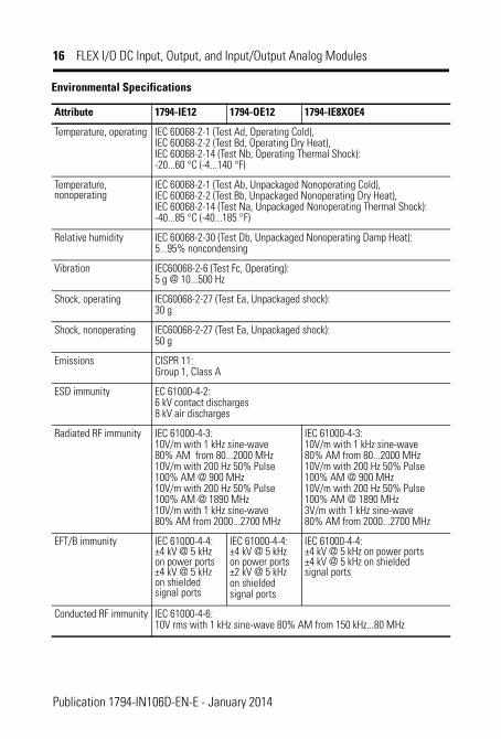
Environmental Specifications
Attribute 1794-IE12 1794-OE12 1794-IE8XOE4
Temperature, operating IEC 60068-2-1 (Test Ad, Operating Cold),IEC 60068-2-2 (Test Bd, Operating Dry Heat),IEC 60068-2-14 (Test Nb, Operating Thermal Shock):-20...60 °C (-4...140 °F)
Temperature, nonoperating
IEC 60068-2-1 (Test Ab, Unpackaged Nonoperating Cold),IEC 60068-2-2 (Test Bb, Unpackaged Nonoperating Dry Heat),IEC 60068-2-14 (Test Na, Unpackaged Nonoperating Thermal Shock):-40...85 °C (-40...185 °F)
Relative humidity IEC 60068-2-30 (Test Db, Unpackaged Nonoperating Damp Heat):5...95% noncondensing
Vibration IEC60068-2-6 (Test Fc, Operating):5 g @ 10...500 Hz
Shock, operating IEC60068-2-27 (Test Ea, Unpackaged shock):30 g
Shock, nonoperating IEC60068-2-27 (Test Ea, Unpackaged shock):50 g
Emissions CISPR 11: Group 1, Class A
ESD immunity EC 61000-4-2:6 kV contact discharges8 kV air discharges
Radiated RF immunity IEC 61000-4-3:10V/m with 1 kHz sine-wave 80% AM from 80...2000 MHz10V/m with 200 Hz 50% Pulse 100% AM @ 900 MHz10V/m with 200 Hz 50% Pulse 100% AM @ 1890 MHz10V/m with 1 kHz sine-wave 80% AM from 2000...2700 MHz
IEC 61000-4-3:10V/m with 1 kHz sine-wave 80% AM from 80...2000 MHz10V/m with 200 Hz 50% Pulse 100% AM @ 900 MHz10V/m with 200 Hz 50% Pulse 100% AM @ 1890 MHz3V/m with 1 kHz sine-wave 80% AM from 2000...2700 MHz
EFT/B immunity IEC 61000-4-4:±4 kV @ 5 kHz on power ports±4 kV @ 5 kHz on shielded signal ports
IEC 61000-4-4:±4 kV @ 5 kHz on power ports±2 kV @ 5 kHz on shielded signal ports
IEC 61000-4-4:±4 kV @ 5 kHz on power ports±4 kV @ 5 kHz on shielded signal ports
Conducted RF immunity IEC 61000-4-6:10V rms with 1 kHz sine-wave 80% AM from 150 kHz...80 MHz
Publication 1794-IN106D-EN-E - January 2014
FLEX I/O DC Input, Output, and Input/Output Analog Modules 17
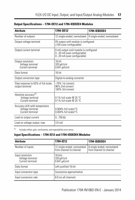
Output Specifications – 1794-OE12 and 1794-IE8XOE4 Modules
Attribute 1794-OE12 1794-IE8XOE4
Number of outputs 12 single-ended, nonisolated 4 single-ended, nonisolated
Output voltage terminal 0V output until module is configured +10V (user configurable)
Output current terminal 0 mA output until module is configured 4...20 mA (user configurable) 0...20 mA (user configurable)
Output resolution Voltage terminal
Current terminal
16 bit 320 μV/cnt 0.641 μA/cnt
Data format 16 bit
Output conversion type Digital-to-analog converter
Step response to 63% of full scale, output terminal
~70% 1st convert; 96% 2nd convert; 100% 3rd convert
Absolute accuracy(1)
Voltage terminal Current terminal
0.1% full scale @ 25 °C 0.1% full scale @ 25 °C
Accuracy drift with temperature Voltage terminal Current terminal
0.004% full scale/°C 0.004% full scale/°C
Load on output current 0...750 Ω
Load on voltage output, max 3.0 mA
(1) Includes offset, gain, nonlinearity, and repeatability error terms.
Input Specifications – 1794-IE12 and 1794-IE8XOE4 Modules
Attribute 1794-IE12 1794-IE8XOE4
Number of inputs 12 single-ended, nonisolated from channel to channel
8 single-ended, nonisolated from channel to channel
Input resolutionVoltage terminal Current terminal
16 bits 320 μV/cnt 0.641 μA/cnt
Data format Left-justified 16-bit
Input conversion type Successive approximation
Input conversion rate 8.0 ms all channels
Publication 1794-IN106D-EN-E - January 2014
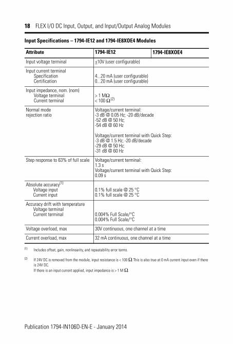
18 FLEX I/O DC Input, Output, and Input/Output Analog Modules
Input voltage terminal +10V (user configurable)
Input current terminal Specification Certification
4...20 mA (user configurable)0...20 mA (user configurable)
Input impedance, nom. (nom) Voltage terminal Current terminal
> 1 MΩ< 100 Ω (2)
Normal mode rejection ratio
Voltage/current terminal: -3 dB @ 0.05 Hz; -20 dB/decade -52 dB @ 50 Hz; -54 dB @ 60 Hz
Voltage/current terminal with Quick Step: -3 dB @ 1.5 Hz; -20 dB/decade -29 dB @ 50 Hz; -31 dB @ 60 Hz
Step response to 63% of full scale Voltage/current terminal: 1.3 s Voltage/current terminal with Quick Step: 0.09 s
Absolute accuracy(1)
Voltage input Current input
0.1% full scale @ 25 °C 0.1% full scale @ 25 °C
Accuracy drift with temperature Voltage terminal Current terminal
0.004% Full Scale/°C 0.004% Full Scale/°C
Voltage overload, max 30V continuous, one channel at a time
Current overload, max 32 mA continuous, one channel at a time
(1) Includes offset, gain, nonlinearity, and repeatability error terms.
(2) If 24V DC is removed from the module, input resistance is < 100 Ω. This is also true at 0 mA current input even if there is 24V DC. If there is an input current applied, input impedance is > 1 M Ω.
Input Specifications – 1794-IE12 and 1794-IE8XOE4 Modules
Attribute 1794-IE12 1794-IE8XOE4
Publication 1794-IN106D-EN-E - January 2014
FLEX I/O DC Input, Output, and Input/Output Analog Modules 19
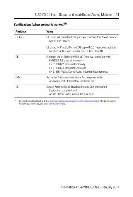
Certifications (when product is marked)(1)
Attribute Value
c-UL-us UL Listed Industrial Control Equipment, certified for US and Canada. See UL File E65584.
UL Listed for Class I, Division 2 Group A,B,C,D Hazardous Locations, certified for U.S. and Canada. See UL File E194810.
CE European Union 2004/108/EC EMC Directive, compliant with: EN50082-2; Industrial Immunity EN 61000-6-2; Industrial Immunity EN 61000-6-4; Industrial Emissions EN 61326; Meas./Control/Lab., Industrial Requirements
C-Tick Australian Radiocommunications Act compliant with: AS/NZS CISPR 11; Industrial Emissions (all)
KC Korean Registration of Broadcasting and Communications Equipment, compliant with: Article 58-2 of Radio Waves Act, Clause 3
(1) See the Product Certification link at http://www.rockwellautomation.com/products/certification/ for Declaration of Conformity, Certificates, and other certification details.
Publication 1794-IN106D-EN-E - January 2014
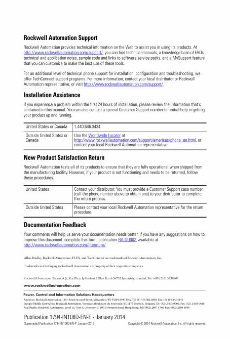
Rockwell Automation SupportRockwell Automation provides technical information on the Web to assist you in using its products. At http://www.rockwellautomation.com/support/, you can find technical manuals, a knowledge base of FAQs, technical and application notes, sample code and links to software service packs, and a MySupport feature that you can customize to make the best use of these tools.
For an additional level of technical phone support for installation, configuration and troubleshooting, we offer TechConnect support programs. For more information, contact your local distributor or Rockwell Automation representative, or visit http://www.rockwellautomation.com/support/.
Installation AssistanceIf you experience a problem within the first 24 hours of installation, please review the information that's contained in this manual. You can also contact a special Customer Support number for initial help in getting your product up and running.
New Product Satisfaction ReturnRockwell Automation tests all of its products to ensure that they are fully operational when shipped from the manufacturing facility. However, if your product is not functioning and needs to be returned, follow these procedures.
Documentation FeedbackYour comments will help us serve your documentation needs better. If you have any suggestions on how to improve this document, complete this form, publication RA-DU002, available at http://www.rockwellautomation.com/literature/.
United States or Canada 1.440.646.3434
Outside United States or Canada
Use the Worldwide Locator at http://www.rockwellautomation.com/support/americas/phone_en.html, or contact your local Rockwell Automation representative.
United States Contact your distributor. You must provide a Customer Support case number (call the phone number above to obtain one) to your distributor to complete the return process.
Outside United States Please contact your local Rockwell Automation representative for the return procedure.
Publication 1794-IN106D-EN-E - January 2014
Allen-Bradley, Rockwell Automation, FLEX, and TechConnect are trademarks of Rockwell Automation, Inc.
Trademarks not belonging to Rockwell Automation are property of their respective companies.
Superseded Publication 1794-IN106C-EN-P January 2013 Copyright © 2014 Rockwell Automation, Inc. All rights reserved.