1797-5.6, flex ex 24v dc non-isolated source 4 output ... · 2 flex ex 24v dc non-isolated source 4...
TRANSCRIPT

Installation Instructions
FLEX Ex 24V dc Non-Isolated Source 4 Output Module
(Cat. No. 1797-OB4D)
Module InstallationThis module must be used with a 1797-TB3 or -TB3S intrinsically safe terminal base unit.
1. Rotate keyswitch (1) on terminal base unit (2) clockwise to position 7 as required for this type of module. Do not change the position of the keyswitch after wiring the terminal base unit
1
2
3
45
6
7
Label here or under here.
8
40231
FLEX Ex is a trademark of Rockwell Automation1 Publication 1797-5.6 - February 2001

2 FLEX Ex 24V dc Non-Isolated Source 4 Output Module
2. Make certain the flexbus connector (3) is pushed all the way to the left to connect with the neighboring terminal base/adapter. You cannot install the module unless the connector is fully extended.
3. Make sure the pins on the bottom of the module are straight so they will align properly with the connector in the terminal base unit.
4. Position the module (4) with its alignment bar (5) aligned with the groove (6) on the terminal base.
5. Press firmly and evenly to seat the module in the terminal base unit. The module is seated when the latching mechanism (7) is locked into the module.
6. Make certain that you only connect terminal base units to other intrinsically safe system modules or adapters to maintain the integrity of the intrinsically-safe backplane.
7. Remove cap plug (8) and attach another intrinsically safe terminal base unit to the right of this terminal base unit if required.
Installation in Zone 1This module must not be exposed to the environment. Provide a suitable metal enclosure. This module has a protection factor of IP20.
ATTENTION
!This module cannot be used in an intrinsically safe environment after it has been exposed to non-intrinsically safe signals.
41307
Publication 1797-5.6 - February 2001

FLEX Ex 24V dc Non-Isolated Source 4 Output Module 3
Electrostatic ChargeProtect the system against electrostatic charge. Post a sign near this module: Attention! Avoid electrostatic charge. For your convenience, a sign which can be cut out is included in this installation instruction.
Removal and Insertion Under Power
European Communities (EC) Directive ComplianceIf this product has the CE mark it is approved for installation within the European Union and EEA regions. It has been designed and tested to meet the following directives.
EMC DirectiveThis product is tested to meet the Council Directive 89/336/EEC Electromagnetic Compatibility (EMC) by applying the following standards, in whole or in part, documented in a technical construction file:
• EN 50081-2 EMC - Generic Emission Standard, Part 2 - Industrial Environment
• EN 50082-2 EMC - Generic Immunity Standard, Part 2 - Industrial Environment
This product is intended for use in an industrial environment.
ATTENTION
!This module is designed so you can remove and insert it under power. However, take special care when removing or inserting this module in an active process. I/O attached to any module being removed or inserted can change states due to its input/output signal changing conditions.
Publication 1797-5.6 - February 2001

4 FLEX Ex 24V dc Non-Isolated Source 4 Output Module
Ex DirectiveThis product is tested to meet the Council Directive 94/9/EC (ATEX 100a) Equipment and Protective systems Intended for Use in Potentially Explosive Atmospheres by applying the following standards:
• EN50014:1992, Electrical Apparatus for Potentially Explosive Atmospheres
• EN50020:1994, Electrical Apparatus for Potentially Explosive Atmospheres - Intrinsic Safety “i”
• prEN50284:1997, Special requirements for construction, test and marking of electrical apparatus of equipment group II, category 1G
OutputsEach output can operate a discrete field device.
Do not apply any non-intrinsically safe signals to this module.
When using an intrinsically safe electrical apparatus according to EN50020, the European Community directives and regulations must be followed.
The channels in this module are electrically connected to each other.
flexbus bus
uC
+V
-V
+
-
powersupply
valveaudiblealarm
solenoid
40069
Publication 1797-5.6 - February 2001
FLEX Ex 24V dc Non-Isolated Source 4 Output Module 5
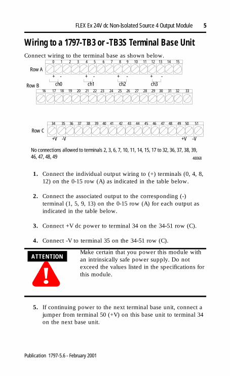
Wiring to a 1797-TB3 or -TB3S Terminal Base UnitConnect wiring to the terminal base as shown below.
1. Connect the individual output wiring to (+) terminals (0, 4, 8, 12) on the 0-15 row (A) as indicated in the table below.
2. Connect the associated output to the corresponding (-) terminal (1, 5, 9, 13) on the 0-15 row (A) for each output as indicated in the table below.
3. Connect +V dc power to terminal 34 on the 34-51 row (C).
4. Connect -V to terminal 35 on the 34-51 row (C).
5. If continuing power to the next terminal base unit, connect a jumper from terminal 50 (+V) on this base unit to terminal 34 on the next base unit.
ATTENTION
!Make certain that you power this module with an intrinsically safe power supply. Do not exceed the values listed in the specifications for this module.
40068
Row A
Row B
Row C
+ + + +- - - -ch0 ch1 ch2 ch3
+V +V-V -V
0 1 2 3 4 5 6 7 8 9 10 11 12 13 14 15
16 17 18 19 20 21 22 23 24 25 26 27 28 29 30 31 32 33
No connections allowed to terminals 2, 3, 6, 7, 10, 11, 14, 15, 17 to 32, 36, 37, 38, 39, 46, 47, 48, 49
34 35 36 37 38 39 40 41 42 43 44 45 46 47 48 49 50 51
Publication 1797-5.6 - February 2001
6 FLEX Ex 24V dc Non-Isolated Source 4 Output Module
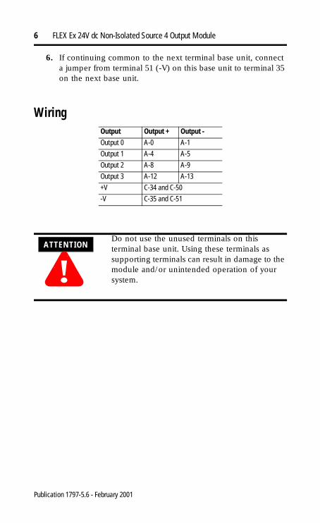
6. If continuing common to the next terminal base unit, connect a jumper from terminal 51 (-V) on this base unit to terminal 35 on the next base unit.
WiringOutput Output + Output -Output 0 A-0 A-1
Output 1 A-4 A-5
Output 2 A-8 A-9
Output 3 A-12 A-13
+V C-34 and C-50
-V C-35 and C-51
ATTENTION
!Do not use the unused terminals on this terminal base unit. Using these terminals as supporting terminals can result in damage to the module and/or unintended operation of your system.
Publication 1797-5.6 - February 2001

FLEX Ex 24V dc Non-Isolated Source 4 Output Module 7
GroundingAll I/O wiring must use shielded wire. Shields must be terminated external to the module, such as bus bars and shield-terminating feed throughs.
Indicators
A = Status Indicators - yellow - individual input present; flashing red - channel fault; solid red - module did not pass powerup check; Channel 0 - solid red while power up check is running
B = Insertable labels for writing individual input designations
C = Power Indicator - green indicates power applied to module
30820-M
Ex1797-OB4D
PWR
A B C 40067
Publication 1797-5.6 - February 2001

8 FLEX Ex 24V dc Non-Isolated Source 4 Output Module
0
0
0
h
Memory Mapping
Cooperative Operation of the ControlNet Ex Adapter and FLEX Ex Output ModulesThe ControlNet Ex adapter (1797-ACNR15) combined with FLEX Ex output module provides a two-tier fault state mechanism. It is important to consider and understand the operation of this mechanism when designing your system.
Two sets of programmable fault states are available, one each in the adapter and output module. This two-tier method is meant to give you a wider fault coverage compared with normal methods.
Adapter Operation
Network Communication Monitoring
The adapter is the primary monitor of network activity. If it detects loss of network communication, it can be programmed to:
• continue writing the last valid received data to the module (hold last state)
• apply local module safe states1
• write a programmable fault state value to the module, depending upon the module type2
DecBit
15 14 13 12 11 10 09 08 07 06 05 04 03 02 01 0
Oct. Bit
17 16 15 14 13 12 11 10 07 06 05 04 03 02 01 0
Read 0
OVL3
OVL2
OVL1
OVL0
F3 F2 F1 F0
Write 0
Out Enb
L FM 3
FM 2
FM 1
FM 0
FS 3
FS 2
FS 1
FS 0
03 02 01 0
Write 1
FR Alarm Filter - C0-3
Where: O = OutputOVL = Overload alarm for individual channelFS = Fault state (0 is reset and 1 is hold last state)FM = Detection of output faults (0 is disable and 1 is enable)L = Latch alarms (0 is disable and 1 is enable)Out Enb = Output EnableFR = Fault reset (0 is normal and 1 is reset)F = Fault alarm for individual channel
Publication 1797-5.6 - February 2001
FLEX Ex 24V dc Non-Isolated Source 4 Output Module 9
This mechanism primarily targets fault behavior for loss of network communication.
Program Mode Behavior
The adapter also monitors the state of the controlling processor or scanner. Two states can be detected: run mode and program mode (idle).
When program mode is detected, the adapter can be configured to:
• continue writing the last valid received data to the module (hold last state)
• apply local module safe states to zero1
• write a programmable fault state value to the module, depending upon the module type2
1 This selection is shown as “Reset Outputs” in RSNetWorx but its action in “Apply Local Module Safe States”.
2 This option is only available in some adapters.
FLEX Ex Output Module Operation
Flexbus Communication MonitoringThe module monitors flexbus communication activity and the state of its Output Enable bit. If it detects loss of flexbus communication activity or the Output Enable bit transitioning to 0, it can be programmed to:
• continue writing the last valid received data to the outputs (hold last state)
• reset the outputs
• write the local module fault state value to the output, depending upon the module type
This mechanism primarily targets fault behavior for loss of backplane communication.
Publication 1797-5.6 - February 2001

10 FLEX Ex 24V dc Non-Isolated Source 4 Output Module
Power-Up State Behavior
The system and modules use the Output Enable bit at system power-up. The power-up state of the Output Enable bit is 0 and must be transitioned to 1 through application program control to initialize activity of a module’s outputs.
Before the Output Enable bit is transitioned to 1, module outputs remain off. Once the initial power-up and application-program control transitions the Output Enable bit to 1, and module output activity begins, subsequent transitions of the Output Enable bit by any source will cause the output module to apply the local module fault state.
RepairThis module is not field-repairable. Any attempt to open this module will void the warranty and IS certification. If repair is necessary, return this module to the factory.
Publication 1797-5.6 - February 2001

FLEX Ex 24V dc Non-Isolated Source 4 Output Module 11
Specifications - 1797-OB4D 4 pt Non-Isolated Source Output ModuleNumber of Outputs 4, non-isolated, sourcingIS Output Type EEx ia IIB/IIC T4,
AEx ia IIC T4,Class I, II, III Division 1 & 2 Groups A-G T4
IS Module Type EEx ib IIB/IIC T4,AEx ib IIC T4,Class I Division 1 & 2 Groups A-D T4
V-I Characteristics Refer to “Output Voltage/Current Capability” on page 20
Load Range 30-5000 ΩFault Detection Fault bits in data table and LED (per channel) blinking
red (1 Hz)Electronic Protection Lead break, overload, short circuitMaximum Output Delay Times
OFF to ONON to OFF
<1.2ms<1.2ms
Indicators 4 yellow status indicators 4 red fault indicators1 green module power indicator
Output (Intrinsically Safe)(16 pin Male and FemaleFlexbus Connector)
Ui < 5.8V dcIi < 400mALi = NegligibleCi < 1.35µF
Isolation PathOutput to Power SupplyOutput to FlexbusPower Supply to FlexbusOutput to Output
Isolation typeGalvanic to DIN EN 50020Galvanic to DIN EN 50020Galvanic to DIN EN 50020None
Power Supply (+V, -V Intrinsically Safe)
Ui < 9.5V dcIi < 1ALi = NegligibleCi = Negligible
Module Field-Side Power Consumption
7.5W
Power Dissipation 5WThermal Dissipation 17.07 BTU/hrModule Location Cat. No. 1797-TB3 or -TB3S Terminal Base UnitConductors Wire Size 12 gauge (4mm2) stranded maximum
1.2mm (3/64in) insulation maximumDimensions 46mm x 94mm x 75mm
(1.8in x 3.7in x 2.95in)Weight 200g (approximate)Keyswitch Position 7
Publication 1797-5.6 - February 2001

12 FLEX Ex 24V dc Non-Isolated Source 4 Output Module
CE, CENELEC I/O Entity ParametersSignal output (+ to -) for ch 0 to ch 3 (terminals: 0-1; 4-5; 8-9; 12-13)
Specifications - 1797-OB4D ContinuedEnvironmental ConditionsOperational Temperature -20 to +70oC (-4 to +158oF)Storage Temperature -40 to +85oC (-40 to +185oF)Relative Humidity 5 to 95% noncondensingShock Operating Tested to 15g peak acceleration, 11(+1)ms pulse width
Nonoperating Tested to 15g peak acceleration, 11(+1)ms pulse widthVibration Tested 2g @ 10-500Hz per IEC68-2-6
Agency CertificationCENELEC II (1) 2G EEx ia/ib IIB/IIC T4UL, C-UL Class I Division 1 & 2 Groups A-D T4
Class I Zone 1 & 2 AEx ib/[ia] IIC T4FM Class I Division 1 Groups A-D T4
Class I Zone 1 AEx ib/[ia] IIC T4CertificatesCENELEC DMT 98 ATEX E 040 X
UL, C-UL UL Certificate Number 99.19699
FM FM Certificate Number 3009806
Protection Group Allowed Capacitance
Allowed Inductance
1797-OB4DUo = 27.4VIo = 110mA
EEx ia IIB 677nF 8mH
IIC 87nF 2mH
If concentrated capacitance and/or inductance are available, use the following values.
EEx ia IIB 150nF 5mH
IIC 30nF 2mH
Class I Division 1 HazardousC US
FM
Publication 1797-5.6 - February 2001

FLEX Ex 24V dc Non-Isolated Source 4 Output Module 13
UL, C-UL I/O Entity ParametersIf this product has the UL/C-UL mark, it has been designed, evaluated, tested, and certified to meet the following standards:
• UL 913, 1988, Intrinsically Safe Apparatus and Associated Apparatus for Use in Class I, II, and III Division 1, Hazardous (Classified) Locations
• UL 1203, Explosion-Proof and Dust-Ignition-Proof Electrical Equipment for Use in Hazardous (Classified) Locations
• UL 2279, Electrical Equipment for Use in Class I, Zone 0, 1, and 2 Hazardous (Classified) Locations
• UL 508, Industrial Control Equipment
• CSA C22.2 No. 157-92, Intrinsically Safe and Non-Incendive Equipment for Use in Hazardous Locations
• CSA C22.2 No. 30-M1986, Explosion-Proof Enclosures for Use in Class I Hazardous Locations
• CSA-E79-0-95, Electrical Apparatus for Explosive Gas Atmospheres, Part 0: General Requirements
• CSA-E79-11-95, Electrical Apparatus for Explosive Gas Atmospheres, Part 11: Intrinsic Safety “i”
• CSA C22.2 No. 14-95, Industrial Control Equipment
Wiring Methods
• Wiring method 1: Each channel is wired separately.
• Wiring method 2: Multiple channels in one cable, providing each channel is separated in accordance with the National Electric Code (NEC) or Canadian Electric Code (CEC).
Publication 1797-5.6 - February 2001

14 FLEX Ex 24V dc Non-Isolated Source 4 Output Module
Table 1Wiring Method
Channel Terminals Voc (V)
Isc (mA)
Vt (V)
It (mA)
Groups Ca (µF)
La (mH)
1 and 2 Any one channel e.g. ch0
0(+), 1(-) 27.4 110.0 - - A, B, IIC 0.03 2.0
C, E, IIB 0.09 8.0
D, F, G, IIA 0.24 16.0
IMPORTANT A terminal base may or may not have an I/O module installed.
1797- OB4DAllen-BradleyB-A
0 1 2 3 4 5 6 7 PWR
7
4 Point Source Output Module
FLEX Ex Discrete Output I/O Module
LEDs
Female Bus Connection
Field Wiring Terminals
Terminal Base
Terminal Base Key
Male Bus Connection
Key Position for Terminal Base Insertion
42058
Publication 1797-5.6 - February 2001

FLEX Ex 24V dc Non-Isolated Source 4 Output Module 15
HaClaClaClaCla
t
Table 2Terminals Vt (V) It (mA) Groups Ca (µF) La (µH)Male Bus Connector
5.8 400 A-G 3.0 3.0
zardous (Classified) Locationss I, Zones 0, 1, & 2 Groups IIC, IIB, IIAss I, Div. 1 & 2 Groups A, B, C, Dss II, Div. 1 & 2 Groups E, F, Gss III, Div. 1 & 2
Hazardous (Classified) LocationClass I, Zones 1 & 2 Groups IIC, IIB, IIAClass I, Div. 1 & 2 Groups A, B, C, D
To any intrinsically safe device or associated apparatus with Entity Concept parameters of Voc < 5.8V; Isc < 400mA.
To any intrinsically safe device or associated apparatus with Entity Concept parameters of Voc < 9.5V; Isc < 1A.
To any IS device with Entity Concept parameters of (Vmax, Imax, Ci, Li) appropriate for connection to associated apparatus with Entity Concepparameters listed in Table 2.
1797-OB4D
16
Shield Connection Only
50
51
35
34
Vmax=5.8VImax=400mACi=1350nFLi=negligible
Vmax=9.5VImax=1ACi=negligibleLi=negligible
Male Bus Connector
úö
ì
ì
ì
ì
33404142434445
0 (+)
÷
Female Bus Connector
Any Simple Apparatus ó or I.S. device with Entity Concept parameters (Vmax, Imax, Ci, Li) appropriate for connection to associated apparatus with Entity Concept parameters listed in Table 1.
1 (-)
ch0
ch1
ch2
ch3
4 (+)5 (-)
8 (+)9 (-)
12 (+)13 (-)
42059
Publication 1797-5.6 - February 2001
16 FLEX Ex 24V dc Non-Isolated Source 4 Output Module
The entity concept allows interconnection of intrinsically safe apparatus with associated apparatus not specifically examined in combination as a system when the approved values of Voc and Isc or Vt and It of the associated apparatus are less than or equal to Vmax and Imax of the intrinsically safe apparatus and the approved values of Ca and La of the associated apparatus are greater than Ci + Ccable and Li + Lcable respectively for the intrinsically safe apparatus.
ó Simple apparatus is defined as a device which neither generates nor stores more than 1.2V, 0.1A, 20µJ, or 25mW.
ì Wiring methods must be in accordance with the National Electric Code, ANSI/NFPA 70, Article 504 and 505 or the Canadian Electric Code CSA C22.1, Part 1, Appendix F. For additional information refer to ANSI/ISA RP12.6.
ö This module, 1797-OB4D, must be used with terminal base 1797-TB3 or 1797-TB3S.
ú Terminals 2, 3, 6, 7, 10, 11, 14, 15, 17-32, 36-39, and 46-49 shall not be connected.
÷ WARNING: Substitution of components may impair intrinsic safety.AVERTISSEMENT: La substitution de composant peut compromettre la securite intrinseque.
FM I/O Entity ParametersIf this product has the FM mark, it has been designed, evaluated, tested, and certified to meet the following standards:
• FM C1. No.3600:1998, Electrical Equipment for Use in Hazardous (Classified) Locations General Requirements
• FM C1. No.3610:1999, Intrinsically Safe Apparatus and Associated Apparatus for Use in Class I, II, III Division 1 Hazardous (Classified) Locations
• FM C1. No.3615:1989, Explosionproof Electrical Equipment General Requirements
• FM C1. No.3810:1989, 1995, Electrical and Electronic Test, Measuring and Process Control Equipment
• ANSI/NEMA 250, 1991, Enclosures for Electrical Equipment
Publication 1797-5.6 - February 2001

FLEX Ex 24V dc Non-Isolated Source 4 Output Module 17
Wiring Methods
• Wiring method 1: Each channel is wired separately.
• Wiring method 2: Multiple channels in one cable, providing each channel is separated in accordance with the National Electric Code (NEC).
Table 1
Wiring Method
Channel Terminals Voc (V)
Isc (mA)
Vt (V)
It (mA)
Groups Ca (µF)
La (mH)
1 and 2 Any one channel e.g. ch0
0(+), 1(-) 27.4 110.0 - - A, B 0.105 3.0
C, E 0.315 9.0
D, F, G 0.840 24.0
IMPORTANT A terminal base may or may not have an I/O module installed.
1797- OB4DAllen-BradleyB-A
0 1 2 3 4 5 6 7 PWR
7
4 Point Source Output Module
FLEX Ex Discrete Output I/O Module
LEDs
Female Bus Connection
Field Wiring Terminals
Terminal Base
Terminal Base Key
Male Bus Connection
Key Position for Terminal Base Insertion
42058
Publication 1797-5.6 - February 2001

18 FLEX Ex 24V dc Non-Isolated Source 4 Output Module
HaClaClaClaCla
n
Table 2Terminals Vt (V) It (mA) Groups Ca (µF) La (µH)Male Bus Connector
5.8 400 A-G 3.0 3.0
zardous (Classified) Locationss I, Zones 0, 1, & 2 Groups IIC, IIB, IIAss I, Div. 1 & 2 Groups A, B, C, Dss II, Div. 1 & 2 Groups E, F, Gss III, Div. 1 & 2
Hazardous (Classified) LocationClass I, Zones 1 Groups IIC, IIB, IIAClass I, Div. 1 Groups A, B, C, D
For connection to other modules refer to the General FM Certification Information on page 29-1 of 1797-6.5.6.
From FM approved devices, 1797-PS2N.
For connection to other modules refer to the General FM Certification Information opage 29-1 of 1797-6.5.6.
1797-OB4D
16
Shield Connection Only
50
51
35
34
Vmax=5.8VImax=400mACi=1350nFLi=negligible
Vmax=9.5VImax=1ACi=negligibleLi=negligible
Male Bus Connector
úö
ì
ì
ì
ì
33404142434445
0 (+)
÷
Female Bus Connector
Any Simple Apparatus ó or FM approved device with Entity Concept parameters (Vmax, Imax, Ci, Li) appropriate for connection to associated apparatus with Entity Concept parameters listed in Table 1.
1 (-)
ch0
ch1
ch2
ch3
4 (+)5 (-)
8 (+)9 (-)
12 (+)13 (-)
42059
Publication 1797-5.6 - February 2001

FLEX Ex 24V dc Non-Isolated Source 4 Output Module 19
The entity concept allows interconnection of intrinsically safe apparatus with associated apparatus not specifically examined in combination as a system when the approved values of Voc and Isc or Vt and It of the associated apparatus are less than or equal to Vmax and Imax of the intrinsically safe apparatus and the approved values of Ca and La of the associated apparatus are greater than Ci + Ccable and Li + Lcable respectively for the intrinsically safe apparatus.
ó Simple apparatus is defined as a device which neither generates nor stores more than 1.2V, 0.1A, 20µJ, or 25mW.
ì Wiring methods must be in accordance with the National Electric Code, ANSI/NFPA 70, Article 504 and 505. For additional information refer to ANSI/ISA RP12.6.
ö This module, 1797-OB4D, must be used with terminal base 1797-TB3 or 1797-TB3S.
ú Terminals 2, 3, 6, 7, 10, 11, 14, 15, 17-32, 36-39, and 46-49 shall not be connected.
÷ WARNING: Substitution of components may impair intrinsic safety.
Publication 1797-5.6 - February 2001
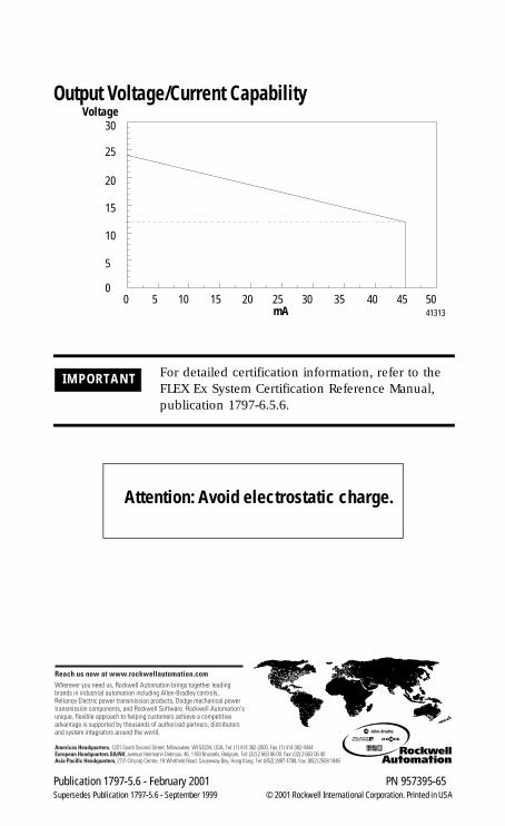
Output Voltage/Current Capability
IMPORTANT For detailed certification information, refer to the FLEX Ex System Certification Reference Manual, publication 1797-6.5.6.
Voltage
mA
30
25
20
15
10
5
00 5 10 15 20 25 30 35 40 45 50
41313
Attention: Avoid electrostatic charge.
Publication 1797-5.6 - February 2001 PN 957395-65Supersedes Publication 1797-5.6 - September 1999 © 2001 Rockwell International Corporation. Printed in USA