18.00 mechanical services v19 - griffith.edu.au · mixed mode ventilation – when designing...
TRANSCRIPT

Design Guidelines & Procedures Version 19 ©
Mechanical Services Section 18.00 / Page 1
18.00 Mechanical Services
The requirements of this Section are generally Mandatory (Refer to Section 1.00) 18.01 Air conditioning & Ventilation 18.01.01 Generally
The following outlines GU’s minimum requirements for air-conditioning and ventilation. Switchboards shall be constructed in accordance with the requirements outlined in Clause 20.08 of Section 20.00 Electrical Services. Wherever possible, small air conditioning systems incorporating small air-handling shall be utilised. These units shall be supplied with chilled water from existing or new campus central chiller water plant. Areas such as lecture theatres, tutorial rooms, laboratories shall have dedicated individual air conditioning units. All air-handling systems shall have adequate fresh air drawn from outside the building via ductwork at locations well away from cooling towers discharges, fume exhausts or traffic. Direct-expansion (DX) refrigeration systems shall be used only where it can de demonstrated that required conditions cannot be achieved by use of chilled water or the area is of a critical nature e.g. computer, data or communication rooms. The use of direct expansion, window mounted or through the wall room air-conditioners (RACs) is strictly prohibited. Should it be found necessary to deviate from the requirements outlined within, written permission from the Superintendent must be sought. Departure from these requirements without prior approval shall be rectified by the consultant/contractor a no expense to Griffith University. Equipment requiring regular service and maintenance shall not be mounted in ceiling spaces. Fan coil units shall be mounted below the ceiling while air handling units shall be floor mounted in dedicated plant rooms or cupboards of adequate size to allow servicing of all components. Ventilation fans shall be mounted in plantrooms wherever possible, rather than above roofs or in ceiling spaces. Air-conditioning systems shall be designed to meet the requirements of AS 1668 Parts 1 and 2 and AS 3666 as well as any other applicable Standard, Regulation or Act including but not limited to AS 1851. Humidity control will not be provided unless specifically called for or where special circumstances dictate. Where special conditions are required these will be nominated by the user and agreed by the Superintendent’s representative. Plant rooms shall be provided with mechanical exhaust ventilation to achieve a minimum of five (5) air changes per minute. Fresh air intake and exhaust grilles shall be located so as to provide effective air flow through the space and to remove heat from equipment and switchboards installed in the plant room. All ductwork, AHUs, filters, fans and the like retained when undertaking refurbishment works, shall be cleaned to remove accumulated dust and mould and treated to prevent mould regrowth. Refer to Section 17.00 Hydraulic Services for insulation treatment of air conditioning condensate pipework.
18.01.02 Specific Requirements
Wet Area Ventilation – Generally, GU requires ‘maze’ style entrances to male and female toilets, shower rooms and change areas. In addition to the ventilation requirements nominated in AS1668 part2, the design must ensure the containment of odours and steam when designing the mechanical systems. Mixed Mode Ventilation – When designing mechanical services for new buildings or major refurbishments, the feasibility of combining natural ventilation, mechanical ventilation and air conditioning shall be investigated. Where possible mechanical ventilation systems and air conditioning shall compliment

Design Guidelines & Procedures Version 19 ©
Mechanical Services Section 18.00 / Page 2
natural ventilation. A changeover system suitable for the application shall be included via the TAC central control and monitoring system. Data Rooms – Data rooms with a floor area equal to or greater than 4m2 shall be air-conditioned via a cool only wall mounted inverter style split DX system. The air conditioning system shall run continuously and automatically restart upon power failure. Data rooms less than 4m2 shall be ventilated with an extraction fan, drawing air form an adjacent air-conditioned space. In refurbishment projects, if a data room is already on a chilled water system, then consideration shall be given to maintaining that system and adding a DX system as a back-up. Photocopy / Print Rooms – Photocopy and print room shall be air-conditioned. Supply and exhaust ventilation rated shall be in accordance with AS1668.2. Laboratory Space – Any building or part of a building used or intended to be used for scientific or technical work which may be hazardous, including research, quality control, testing, teaching, preparation, analysis, support areas etc must comply with the Building Code of Australia, AS 2982, AS 2243 Parts 1-10 inclusive, AS 1940, AS 4332, AS 2430, AS/NZ 2982.1 and referenced and related documents including the Workplace Health and Safety Act and regulations. Where laboratory space is not designated PC2, provisions shall be built in which allow the upgrade to Physical Containment Level 2 (PC2) standards as defined in AS 2243-3. Provisions shall include, but not be limited to, ductwork for extraction systems, discharge stacks, plant room space, electrical capacity, plumbing and drainage and other building related items. Design of laboratory space shall also be mindful of this requirement. For Physical Containment (PC) laboratory spaces, the design consultant shall provide an air flow schematic drawing detailing the method of achieving a negative differential air pressure in the laboratory relative to the spaces outside the boundary of the PC space. It may be necessary to achieve an air pressure differential between adjoining rooms and air locks. The method of achieving the pressure differential for various spaces must be discussed with and approved by the CLF mechanical Engineer and the space User. In some instances it may be necessary to install specific exhaust systems to achieve a negative air pressure in the laboratory. This exhaust system shall be controlled by the CCMS and linked to pressure sensors mounted on each side of any door in the laboratory perimeter walls. The exhaust and air conditioning systems shall be linked via the BMS so that should the negative pressure within the laboratory spaces fail, then the air conditioning will shut down and an alarm will be generated. On completion of the project and during the commissioning of the facility, an air pressure differential test shall be carried out to confirm the design and compliance with physical containment requirements. UVC System for Kitchen Hoods – All kitchen exhaust hoods shall be installed with a water wash system combined with a UVC system similar to the ‘Capture-ray’ technology manufactured by Halton. The UV lights shall be capable of easily maintenance and replacement. Alternative similar technology with equal and proven performance will be acceptable subject to the approval of the CLF Mechanical Engineer.
18.01.03 Design Conditions & Performance Standards
Careful consideration must be given to the design conditions for various areas. The following design assumptions may be made: External Design Conditions – Summer General Teaching, Research and Office Areas
Logan Campus 33.1°C DB / 24.8°C WB All other campuses 31.9°C DB / 24.9°C WB
Critical Areas (Computer Facilities, Critical Research Areas etc.)
All campuses 33.5°C DB / 26.0°C WB
External Design Conditions – Winter General Teaching, Research and Office Areas
Logan Campus 7.5°C DB All other campuses 9.3°C DB
Critical Areas (Critical Research Areas etc)

Design Guidelines & Procedures Version 19 ©
Mechanical Services Section 18.00 / Page 3
All campuses 6.0°C
Hours of Operation – Normal hours of operation for teaching areas are between 8.00 am and 10.00 pm Monday to Friday and office areas are 8.00 am to 5.30 pm Monday to Friday. Research Facilities, Computer Laboratories and Communication Rooms may require twenty-four operation. Population Densities – Population densities can be taken to be approximately equal to those shown below:
General Office 10.0 m2/person Interview Rooms 5.0m2/person Library Reading Rooms 2.5m2/person Laboratory – Undergraduate (1st year) 3.7 m2/person Laboratory – Undergraduate (other years) 4.7 m2/person Laboratory – Postgraduate 12 m2/person Seminar Rooms 1.8 m2/person Lecture Theatres 1.1 m2/person
Internal Design Conditions, Summer – The following design conditions shall apply unless specifically nominated otherwise;
Teaching Areas, Office Areas etc. 23.5°C DB +/- 1°C
55% RH nominal Laboratories 22.5°C DB +/- 1°C
65% RH maximum
Internal Design Conditions, Winter – The following design conditions shall apply unless specifically nominated otherwise;
All areas 21.0°C +/- 1°C
Chilled Water Temperatures – For design purposes the following chilled temperatures may be assumed:
Supply Water Temperature 7°C Return Water Temperature 13°C
Noise Levels
Room Type LAeg LA01
Faculty Offices and all other individual offices 37 dBA 45 dBA
Administrative/clerical office (open space), post graduate student areas 37 dBA 50 dBA
Counselling office 37 dBA 45 dBA
Teaching Room 37 dBA 45 dBA
Lecture Theatre 32 dBA 40 dBA
Library 40 dBA 50 dBA
Video-conferencing Room 32 dBA 40 dBA
Corridors, Lobbies 45 dBA 55 dBA
18.01.04 Vibration control
The system shall be designed to eliminate the transmission of noise and vibration from air-conditioning and mechanical equipment to the space and the building structure. Sound attenuators and/or insulated ductwork shall be installed where necessary to eliminate the transmission of fan noise. Where reciprocating or rotating equipment is installed, it shall be isolated from the structure by vibration isolators. The Consultants and/or Contractors shall replace any equipment or system found to exceed the nominated noise levels at no cost to the University.
Design Guidelines & Procedures Version 19 ©
Mechanical Services Section 18.00 / Page 4
18.01.05 Equipment, Warranties & Maintenance
Major mechanical plant (e.g. Chillers, pumps, fans, air handling units, fume cupboards, filters, fan coil units, DX Units, DDC equipment, Variable Speed Drives, Fume Cupboards, Exhaust Hoods, Compressors, Vacuum Units, Cold rooms, Constant temperature Rooms, etc.) shall be provided with full manufacturer’s warranty for a period of two (2) years from practical completion. Maintenance and servicing of the Mechanical Services installation shall be carried out by the Contractor for a period of twelve (12) months after Practical Completion.
08.01.06 Piping, Valves & Fittings
All pipework internally within a building shall be of Type B Copper except condensate drains, which shall be class 12 PVC. Where fixing brackets or clips to copper pipework are of a dissimilar metal, they shall be effectively isolated from the pipework with plastic tape or similar material to prevent corrosion. Paint finishes are not acceptable as an isolating medium. Internal pipework shall be installed in service ducts, risers or ceiling spaces to the approval of the Superintendent. Pipework shall be easily accessible for maintenance or modifications. All the return chilled water pipes at the Chiller Plant shall be installed in such a way that allows for complete mixing of all return water before passing the Chiller staging sensor. Pipework immediately prior to the inlet of any water meter, energy meter or any measuring device installed on the pipework, shall be in a straight length of not less than ten (10) times the pipe diameter. Valves shall be of approved manufacture to confirm to AS MP52 and shall be in easily accessible positions. Provide ceiling markers to easily identify the location of equipment above ceilings. Valves and fittings laid in-ground shall be flanged and located in drained concrete service pits and shall have 316 stainless steel bolts and washers. Transition from one material to another should be made adjacent to the buildings in a concrete services pit. Ball or resilient seat valves shall be used thoughout except where throttling is required in which case ‘Tour and Anderson’ Stat and ‘Stad’ or approved equal valves shall be specified. Valves shall be butterfly lever action up to 150-mm DIA and geared action 150-mm DIA and above. Chilled water control valves shall be rated to resist the system pressure when shut and offer satisfactory authority of the system pressures at that point. All valves shall be labelled for their service and function using engraved discs to the approval of the Superintendent. Valves shall be scheduled and detailed in the maintenance manuals. All valves shall have extended shafts to accommodate complete insulation of the pipework. Incoming mains and main distribution pipes shall be installed of a size adequate to permit connection of future buildings or any expansion. The requirements are to be discussed with the Superintendent and generally follow the site master plan. Pipes that pass through floors or walls shall have sleeves filled with appropriate insulation or fire rated material to suit the application. Provide suitably sized pipework risers within the building to service every building level. Provide dirt legs and drains at the bottom of each riser, fitted with hose cocks. Pipework risers shall incorporate dedicated isolating valves at every building level take-off and at all other significant sub branch pipework runs. It shall be possible to isolate each building level and sub branch without disrupting the chilled water service to other levels and sub-branches. Provide drains at the lowest points in the chilled water system on each building level. Automatic air bleeds complete with an isolation valve and drain to nearest waste pipe, shall only be installed at the highest point of the chilled water reticulation system such as the top of vertical risers via a T junction and a short riser extension, and not on horizontal pipe runs. Chilled water campus reticulation pipework between buildings etc, shall be buried in the ground and shall be ‘Blue Brute’ or ‘HDPE’. Thrust blocks must be installed at all junctions and changes in direction. Where future buildings are planned, provide valved take-offs for future connections located in services pits located adjacent future building sites. Pipework shall be sized to accommodate future building as indicated on the campus Master Plan.

Design Guidelines & Procedures Version 19 ©
Mechanical Services Section 18.00 / Page 5
All screwed valves and fittings shall have unions for easy removal without cutting the pipework. ‘Binda’ cocks shall be fitted to all at all air-handling units, fan coil units, pumps etc and shall extend a minimum of 15mm beyond the outside surface of the insulation. ‘Binda’ cocks shall be located next to all DDC sensors for calibration and test purposes. On completion, all pipework shall be chemically cleaned, flushed and drained. The Contractor shall allow sufficient chemicals to be provided to dose the chilled water system through the dosing tank. Chemicals shall be those used by the University.
08.01.07 Ductwork & Registers
Main riser ducts shall be capable of handling an increase of 15% in air quantity. Fans and motors should be selected with this in mind. Ductwork, solid and flexible, shall be constructed an installed in accordance with AS 5254. Flexible ductwork shall be supported by packaging straps, buckles and mesh saddles not less than 300mm long, to suit the duct diameter. Provide locking quadrants to all adjustable dampers including spigot and butterfly dampers. Supply air ductwork immediately prior to the inlet of a VAV box shall be in a straight length of not less than ten (10) times the width of the duct. Insulation to air conditioning ductwork shall be applied to the external, not the internal surfaces of the duct to minimise the growth of mould and collection of dust. Internal insulation of ductwork shall only be installed with the prior approval of the Superintendent. If internal insulation is approved, then easily accessible access panels shall provided in the ductwork for cleaning and inspection. Any internal insulation shall be faced with perforated galvanised steel sheet for ease of cleaning and to ensure that the insulation does not separate from the duct wall over time. Where ductwork is exposed to view in occupied spaces, all ductwork whether insulated, or uninsulated, shall be spiral wound circular or oval duct. Where ductwork is exposed to weather, it shall be profiled to shed water. Ductwork exposed above roofline excluding fume exhausts shall be constructed from ‘Colorbond’ sheet steel to match the roof colour. External ducts shall be graded to prevent ponding and all joints shall be sealed with an approved sealant. Joints in exposed ductwork shall be pocket and tail joints or similar to provide a smooth neat appearance. Longitudinal joints shall be of the Pittsburgh type with a smooth interior finish. Standing seams shall not be permitted. All duct joints shall be secured by using self-tapping screws or blind head pop rivets and sealed airtight with ‘3M EC800’ duct sealer Duct supports shall not be used to support piping, ceiling and any other loads additional to the ductwork. Provide duct access panels in the risers at each floor and in each branch or sub-branch for cleaning purposes. Duct access panels shall be not more than 10 metres apart. Duct access panels minimum size 300 x 200mm shall be ‘Bullock’ brand and the location of access panels above ceilings shall be coordinated with the ceiling grid, light fittings and equipment layout. Where these access panels are visible they shall be fitted with ‘Larkspur’ catches. Ceiling registers shall be of the square louvers-faced type of ‘Bradford’, Holyoake’, ‘Dragon’ or other approved manufacture with removable cores. The interior of ductwork behind registers shall be painted black. Wall registers shall be of the adjustable blade type with the front set of blades horizontal. Maximum blade spacing shall be 20mm. All exhaust and return air grilles shall be square or rectangular one-way Louvre faced type grilles similar in appearance to the general ceiling registers, and with removable cores. Ductwork penetrations to walls and floors shall be packed with an approved insulation (fire rated if required) and shall be flanged on both sides of the penetrations. Flexible ducts shall be sleeved where they penetrate full height walls.

Design Guidelines & Procedures Version 19 ©
Mechanical Services Section 18.00 / Page 6
Fan coil units fresh air intakes to be fitted with CAR (Control Air Regulators) when supplied from a mechanical outside air system. Outside air intakes shall be provided with easily removable media filters to pre-filter the air before it enters the unit(s). Outside air grilles shall be anodised aluminium, minimum 20 microns, to match the exterior colour scheme of the building (no ‘Colorbond’). Provide removable vermin mesh behind all external louvers. To eliminate condensation on ductwork which can potentially cause water damage to ceilings, light fittings, electronic equipment etc, the following must be considered;
All return, discharge and exhaust ductwork including all applications for air conditioning, fume cupboard extraction, laboratory pressurisation systems, vacuum systems, dangerous goods cabinet discharge etc. which are subject to an internal air temperature lower than the surrounding air temperature, may be subject to the formation of condensation on its external surfaces.
The forming of condensation on external duct surfaces will be more prevalent when the ducts pass through plant rooms, service risers, ceiling voids and any enclosed spaces which will contain stagnant untreated ambient air.
Ceiling voids shall not be assumed to have the same controlled indoor conditions as exist in the air conditioned spaces over which they occur.
External insulation shall be provided around ductwork wherever there is a chance that condensation may form including but not limited to the situations previous mentioned.
18.01.08 Insulation to Pipework
Insulation to chilled water pipework shall be ‘Koolfoam Ultra’ or approved equal sectional, preformed grey EPS insulation complying with AS1366 Part 3. Insulation shall be factory faced with ‘Sisalation 450’ (extra heavy duty grade) aluminium foil insulation. Insulation sections shall be adhered to the pipes and sealed at ends with ‘Denso Vapourseal Primer’ or approved equal non setting gel sealant applied strictly in accordance with the manufacturer’s printed instructions in sufficient thickness to eliminate all air voids. All joints in the length and at the ends of sections shall be further sealed using 50mm reinforced aluminium foil self adhesive tape. Cut, trim and seal insulation around all bends, junctions and the like in a workmanlike manner. The thickness of the insulation shall generally be as follows;
25mm thick for pipe up to 25mm dia. 40mm thick for pipe 32mm and 40mm dia. 50mm thick for pipe 50mm dia. or larger
If the ceiling space in existing buildings is restricted, it may not be possible to comply with the foregoing specification for insulation material thicknesses. In situations where this occurs, any change to thicknesses must be approved by the GU Mechanical Engineer and the Superintendent. All spacer blocks at hangers and supports shall be inorganic closed cell high density polyurethane insulating blocks. Wood blocks are prohibited. Insulated pipework exposed externally shall be fully sheathed in ‘Colourbond’ steel. Insulated pipework in plant rooms and walk-in risers and ducts shall be metal sheathed with .5mm zinc annealed to a minimum height of 2700mm. Edges shall be swaged and overlapped 50mm. Metal straps shall be used at 500 max centres. Any penetrations of the metal sheathing shall be effectively sealed to ensure that the vapour barrier Is maintained and rusting prevented. Condensate drains shall be continuously insulated with approved elastomeric closed cell insulation, minimum 9mm wall thickness equivalent to ‘Armaflex’. All joints shall be glued with approved adhesive in accordance with the manufacturer’s recommendation. To eliminate the problem of condensation on chilled water pipework installed internally to buildings which causes water damage to ceilings, light fittings, electronic equipment and the like, the following shall be considered when designing and installing pipework and insulation;
Weak points inherently exist in the insulation to chilled water pipework such as at the valves, ‘binda’ points, special joints, elbows etc.
These weak points may exist not as a result of poor workmanship, but for other reasons such as the need to access these fittings for system monitoring or maintenance from time to time, and constricted ceiling space making installation difficult.

Design Guidelines & Procedures Version 19 ©
Mechanical Services Section 18.00 / Page 7
Design and installation of the pipework must identify and seek to strategically locate these potential weak points to provide easy accessibility for both installation and servicing.
Drip trays with gravity drainage shall be provided under all weak points to eliminate the potential for damage as previously described.
Both drip trays and drainage pipes shall be provided with adequate fall gradients to ensure that cold condensate water does not lie in the tray or drain pipe and become an additional condensation source. Insulate trays and drain pipes if limited falls only are achievable.
18.01.09 Plant & Equipment
Pumps – Pumps shall be Back-End-Pull-Out type wherever possible, ‘Ajax 2000 Series’ or ‘Southern Cross’. Impellers shall be bronze, casings gunmetal and shafts etc stainless steel. Chilled water pump selection shall be based on their suitability to the duty. The pump casing and electric motor shall be sized to accommodate an impellor two standard sizes larger than selected. Stainless steel drip trays are to be mounted on concrete inertia bases complete with spring mounts. In all cases, dual pumps shall be provided complete with variable speed drives (VSD) for balancing or controlling purposes. Each secondary/tertiary chilled water pump shall be sized to accommodate 65% of the required design water flow. Where more that one (1) chiller/pump combination is utilised together, a single primary chilled water pump and VSD is acceptable. Motors – Motors shall be totally enclosed fan cooled and normally be limited to 1450 rpm maximum. Motors shall have an IP56 rating. Belts, pulleys and couplings shall be protected by the use of easily removable and replaceable guards. Motors rated at more that 10kW shall be provided with a lifting eye. All motors rated at 5.5kw and above shall be of the Premium Efficiency type (‘TECO Max-E2’ or equivalent). Hot Water Heating Coils – Heating of air shall be by means of hot water coils fitted to Air Handling Units (AHU) or air Pre Conditioners located generally in plant rooms. Hot water shall be generated by heat pumps and circulated by an in-line pump with a controlled variable speed drive that varies the rate of circulation of the water through the coils depending on the amount of heat required. Heat pumps for air heating shall be Quantum Titan or approved equal commercial range units located centrally in a separate plant room with cold air discharge to the outside of the building. If three or more units are required they shall be manifolded together to achieve an equal flow output. Electric Heater Banks - The use of electric heater banks shall only be considered if there is no alternative and is to be approved by CLF. Heater banks shall be located generally in plant rooms and shall be clearly identified using ‘Safetyman’ labels. Heater banks shall be of a physical size that gives maximum coverage to allow for effective heat transfer and to ensure that no air bypasses the heater bank. The HPT for duct heaters shall be generally positioned 250mm downstream from the heater bank. Heaters on fan coil units shall be of the low surface temperature type and sized to fit the full extent of the air outlet. Heater banks shall be fully balanced over all three phases. HPTs shall be ‘Penn A25’ type only, and shall be mounted in an easily accessible place no closer to the heaters than 200mm in horizontal ducts and 300mm in vertical ducts. ‘Klixon’ brand thermostats are not acceptable. There shall be a switch capable of acting as a ‘lock-out’ device located immediately adjacent to the heater bank to isolate all power feeding those heaters. Isolating the control circuit only is not acceptable. Filters – The following is a guide to the type of filters to be specified:
Filters Details
Built-up air-handling units ‘Pyracube’ or ‘Four Peak”
Unitary fan coil units ‘Email SP’ series panel filter
Grease filters ‘Email’ Type GW
Dry media filters serving air-handling plant shall be of the disposable type and comply with the requirements of AS 1668 Part 2 for Dust No.1 efficiencies. Panel filters serving fan coil units shall be washable. Fresh air intakes shall include accessible pre-filters.

Design Guidelines & Procedures Version 19 ©
Mechanical Services Section 18.00 / Page 8
Filter banks shall be provided with manometers. The manometers shall be mounted in an easily accessible and visible location and shall be ‘Dwyer Magnahelic’ or equal. The initial and final pressure drop reading shall be clearly marked adjacent the gauge on a fixed label of approved type. Before starting any air handling system, install the correct filters in their frames together with a rough filter across the face. Upon completion of commission, the rough filter shall be removed and the manometers calibrated to show clean filter pressure setting. Filters shall be replaced at the end of the defect liability period. Chiller Sets – Chillers of ‘York’, ‘Trane’ or approved manufacture. Chiller Sets when installed on site shall be complete with a communications port for connection to the BMS, and shall conform to an open standard protocol e.g. Backnet (preferred), Lon, Mobus etc. Additional chillers shall be compatible with existing equipment. All chiller units shall be raised above plant room/enclosure floor slabs on corrosion protected supports to allow easy removal of leaf litter and the like which may accumulate under the unit. All chillers installed in a corrosive environment shall have enhanced corrosion protection to painted and galvanised surfaces, and the condenser coil fins to air cooled units shall be protect with a factory applied treatment to the approval of CLF. Cooling Towers – cooling Towers shall be stainless steel or fibre glass. Towers shall comply with all relevant codes, standards, acts and regulations. Particular care is to be taken with respect to the possibility of introducing Legionnaire’s Disease as a result of tower placement. Particular care shall also be taken to ensure that statutory requirements relating to noise levels are met. Cooling Tower fan motors shall be provided with variable speed drives for controlling purposes. Water treatment systems of the highest quality are required. The details shall be agreed with the superintendents’ representative in advance. Air Cooled Condensers – Air Cooled Condensers shall be of approved manufacture and should preferably be of the vertical airflow type. Where multiple compressors are installed, each compressor shall be capable of being individually isolated of maintenance and for fault. Belts and Pulleys – All belt driven equipment shall have a minimum of two vee belts. All equipment pulleys shall be equivalent to ‘Taperlock”. Pulleys shall be arranged to allow future adjustment in either direction at commissioning. Pulley systems, which are at the extreme of adjustment, will be rejected. Unitary Fan Coil Units – Unitary Fan Coil Units shall by ‘Sinko’ brand (or similar approved by CLF), either floor mounted or suspended below the false ceiling. Units provided with wall mounted fan speed control e.g. Faculty Offices, could be selected at high speed. Units serving all other spaces shall be selected at medium speed. Please note, the final unit selection may be dictated by its heating capacity. Air Handling Units – Air handling units shall be of ‘Fan Coil Industries’, ‘Colair’, ‘Air Design’ or ‘Walker’ manufacture, designed for easy, safe access to all internal components. Access panels shall have at least two (2) D handles and be locked with spring loaded ‘Larkspur’ catches. Access panels larger than 600 x 600. The use of screw fixings in the manufacture of the units is not acceptable. Any internal insulation subject to damage shall be protected by the use of perforated metal or other means. Drip trays shall be stainless steel, formed to provide a sump and shall be adequately drained. Drip trays, which hold water, will be rejected and replaced by the Contractor. Drains shall be trapped and treated as Trade Waste, run to the Sewer system by means of a tundish. Traps shall be easily removable by means of pressure barrel unions. The face velocity at the cooling coil shall not exceed 2.3 m/s. Equipment Location – All equipment shall be located in easily accessible adequately sized plant rooms unless otherwise approved by CLF. Clearances around the mechanical switchboards shall meet the requirements of AS 3000.
18.01.10 Air-Conditioning Electrical System
Switchboards and Motor Control Centres shall normally be of type-tested construction with IP rating approved by the superintendent prior to tendering. Switchboards shall be electrical orange (X15 to AS 2700) externally and white internally. All components shall be located on the rear panel in orderly manner. No components are to be mounted on the sides or base of the switchboard and they shall be mounted not less than 300mm above the floor.

Design Guidelines & Procedures Version 19 ©
Mechanical Services Section 18.00 / Page 9
Permanent, clearly legible traffolyte labels screw fixed to all internal and external controls. Fire Alarm Relays shall be provided in accordance with the requirements of AS 1668 and AS 1670 as applicable. Provide spare space and capacity in all switchboards, sub-boards and control panels to allow for future expansion. This spare capacity also applies to the switchboard sub-mains etc. The amount of spare capacity shall suit the situation and be agreed upon and approved by the Superintendent prior to manufacture, but in no instance shall be less than 10%. A Polyphase kilowatt-hour meter complete with pulsed output to the CCMS shall be provided to the air-conditioning section on the main electrical switchboard. This meter shall be suitably labelled and grouped with all other meters. Refer to Section 20.00 Clause 20.08 for further details of meter installation. All cables shall be run on cable trays, ladders, catenary wire etc and terminated in terminal strips. All cables entering switchboards shall enter the switchboards through a gland nut and be terminated on a terminal block, labelled as to its origin and numbered. All active, neutral, earth and control wiring shall be number ferruled both in the switchboard and at field terminations corresponding to circuit breaker numbers. Wrap around tape numbering systems are not acceptable to the Superintendent. Multi-joining of cables prior to termination on bars is not acceptable. Neutral and earth bars shall have the same number of terminations as circuit breaker positions and shall include two grub screws per terminal. All cabling shall comply with the requirements of Section 20.00 Electrical Services. The MSSB shall include ‘Auto/Off/Manual’ switches for each piece of equipment served except for VAV boxes which will have a common heater ‘Auto/Off/Manual’ switch (refer to GU Standard Drawing No. GSD–600). For all VAV heater banks, a HPT fault indicator light for each VAV unit shall also be provided on the MSSB fascia. Approved electrical and control drawings shall be prepared and supplied with the switchboard by the Date of Practical Completion. Provide a GPO in all switchboards and a fluorescent lamp in each switchboard cupboard greater than 2m2 in face area. All mechanical switchboards shall have a lamp test facility incorporated into the control system via relays and not diodes. All mechanical boards with DDC control shall have the low voltage and DDC controls mounted on the right-hand side of the board while the 240V/415V equipment shall be mounted on the left-hand side. Separate DDC boards will only be accepted where approved. All boards shall be adequately vented to remove heat and locked via an ‘L&F 92268’ key. A triple RJ45 socket shall be installed within the DDC board in a location that is determined by the controls system installer to enable the board to be connected to the GU network. DDC cables shall be screened and not run adjacent to any 240V electrical cables. Separate ducting shall be provided within the switchboard to separate DDC and power cables. The following equipment shall be used in the Air-Conditioning control System;
All Relays RELECO 11 Pin, Circular Base All Timers RELECO 11 Pin, Circular Base Contractors “Sprecher and Schuh’ or other approved equal Control Switchers ‘Kraus and Naimer CG4’ (not lockable) Indicator Lamps L.E.D. Multi array type Circuit Breakers ‘Merlin Gerrin’ or ‘Clipsal 4 series Power Range’
The electrical supply to mechanical sub-boards must be taken from the main mechanical switchboard or the mechanical services section of the building MSB. Under no circumstances shall the electrical supply be taken from the buildings general light and power distribution boards.

Design Guidelines & Procedures Version 19 ©
Mechanical Services Section 18.00 / Page 10
18.01.11 Identification of Equipment
All items of equipment, both in plant rooms and in the field, shall be suitably identified with traffolyte labels of an approved size and type. All mechanical and control items shall be similarly labelled to indicate their function. Provide ceiling markers to locate services and equipment above ceilings. All valves within the chilled water system shall be tagged and scheduled in the maintenance manuals for future reference. Number mechanical equipment according to the room number or area which it serves.
18.01.12 Identification of Pipework & Ductwork
All pipes and ductwork shall be identified in accordance with AS 1345 – Identification of the contents of Piping, Conduits and Ducts, and AS 1318 – SAA industrial Safety Colour Code and AS 2700 – Colour Standards for General Purposes. Extra labelling shall be provided if requested by the Superintendant for clear identification of any pipework or ductwork. The ground colour shall be applied to a length of not less than 300mm where the ground colour shall be used in conjunction with adhesive levels for identification. The location of identification marking shall be at intervals of not more than 3m and adjacent to branches, junctions, valves, both sided of walls and control points. Such marking shall be placed so that they are easily seen from all approaches. Safety colours where applied shall be over a length on not less than 75mm at locations and intervals as nominated for ground colours Ground colours used in conjunction with safety colours shall be applied to each side of the safety colour. ‘Safetyman’ adhesive labels are an acceptable method for identification of pipework. Flow direction arrows shall be provided to all pipework and the Flow and Return-pipes shall be identified with labels, which say ‘Chilled Water Flow’ and ‘Chilled Water Return’ as appropriate.
18.01.13 Future Expansion & Construction
Proper consideration must be given to the design of mechanical services which initially will not be fully utilised or which form part of a Master Plan. Design issues to be considered shall include but not be limited to chilled water supply, size of plant rooms, provision and/or size of service ducts and risers, capacity of equipment, electrical supplies etc. These requirements shall be discussed with CLF.
18.01.14 Air-Conditioning Controls
DDC systems shall be adopted. Other control systems shall not be used without the approval of CLF. All AHUs and FCUs which do not have a requirement for a Constant Temperature Set Point, shall have an Effective Set Points calculated by combining the sum of the Base Set Point +/- Global Offset +/- Local Offset + 50 C for cooling and – 50 C for heating. Should a Global Offset be applied due to a rise or fall in ambient temperature, then this must not alter the heating or cooling Effective Set Points. Air-handling units serving individual areas such as lecture theatres. Testing laboratories, computer services, seminar, tutorial and meeting rooms, shall be controlled by Movement Detector operated switching with adjustable time delay of at least 30 minutes to some areas. The detector shall be specially designed for energy management purposes and be approved by CLF. More than one sensor may be required to cover the entire area. Where movement detectors are used, the sensor only will be installed in the space and the switching relays located in plant rooms. Over-riding time control shall be provided by means of the Central Control and Monitoring System (CCMS). Air handling units serving diverse areas or general offices shall be fully automatic in operation and shall be provided with time switch controls. Time programming shall be provided through the CCMS. After hours push buttons shall be provided where required. VAV controllers to individual areas within like spaces shall not be used without the specific approval of the Associate Director, Capital Works CLF. If approved, the air handling fan shall have a variable speed drive controlled by a duct pressure sensor providing feedback on the drive speed.

Design Guidelines & Procedures Version 19 ©
Mechanical Services Section 18.00 / Page 11
Refrigeration plant shall be fully automatic and shall normally respond to a call for cooling from any air-handling unit. Local exhaust fans (other than toilet exhaust) all be provided with local manual controls. Provision shall be made on all controls and sensors for connection to a CCMS in accordance with Appendix A to this Section. Control and monitoring systems for air-conditioning plant shall be determined in consultation with staff of CLF prior to finalisation of specification. Refer to Appendix A for the minimum requirements. Chilled water pump controls shall incorporate pressure switches on the suction and discharge sides of the pump wired in series with the control to the chiller contractor to act as an interlock. Dual secondary/tertiary chilled water pumps shall be fitted complete with variable speed drives with the control such that both pumps will ramp up to maintain the required flow. When the flow decreases below 65% the lag pump will shut down and the lead pump will speed up to maintain the flow. In either case the pump shall be controlled by a differential pressure switch located two-thirds along the Index run of the respective chilled water system.
18.01.15 Central Control & Monitoring System (CCMS)
All new buildings and refurbishment or alteration of existing buildings, shall include for full connection to the GU existing CCMS system with exposure of points as directed via BacNet to the GU IP network. The existing CCMS system is a combination of Schneider Electric (formerly T.A.C. Pacific Pty Ltd) ‘INet’, ‘Vista’ and ‘StruxtureWare’ systems. All new buildings shall use ‘StruxtureWare’, or approved equal, as outlined later herein. When refurbishment or upgrade works are undertaken within an existing building, the existing CCMS system shall be extended or modified accordingly subject to the approval of CLF, unless the extent of work justifies the conversion of the whole building to the current preferred ‘StruxtureWare’ system. Older buildings and certain campuses are controlled using the ‘T.A.C. INet’ system, however no new ‘INet’ system or equipment is to be installed. For new buildings, where the system is independent of any existing installation, then an alternative system of approve manufacture, with equivalent technical performance to the Schneider StuxtureWare system, may be considered. If an alternative system is approved following and evaluation by CLF, the system manufacturer shall provide all necessary software an training to permit the University’s engineering and maintenance staff to perform remote control, monitoring and other related functions on the existing CCMS central computer hardware.
The mechanical engineering consultant shall consult with CLF and the approved specialist CCMS provider to develop a functional brief for the air conditioning control strategy for all areas of a new building or a major refurbishment before design documentation is commenced. The functional brief shall identify the space, space usage, specific requirements and any other considerations that may be considered necessary to achieve the desired control strategy. All DDC installations shall be carried out by specialist contractors approved by the Superintendent. Power to the DDC control panels shall be 240V/24V with capacity to operate the maximum relays controlled by the DDC. All controls emanating from the DDC to external devices shall be 24VDC or 24VAC originating from a 240V/24V transformer mounted within the DDC section of the MSSB and switched by the internal relays within the DDC control panel. A triple RJ45 data port shall be installed within the DDC section of the MSB in a position determined by the control system installer. The specialist contractor shall provide not less than eight hours of operational and programming instruction on the DDC system to staff nominated by the Superintendent. Refer to Appendix A to this Section for minimum requirements. All new chiller loads and heater bank loads shall be connected to the existing Demand Control program modules. Relevant temperature set points shall be connected to the existing Global Temperature Reset program modules. Where a building is stand alone with respect to Supply Authority Metering, i.e. not existing

Design Guidelines & Procedures Version 19 ©
Mechanical Services Section 18.00 / Page 12
Demand Control or temperature reset programming, Demand Control and Global Temperature Reset programming shall be provided as part of the contract. Laboratories and some other special areas shall be exempt. Provide a CLF approved UPS with power monitoring card to be housed in the CCMS switchboard in each building. The UPS shall be fed from a dedicated special pin power point located within the switchboard and suitably signed with an engraved Trafolite label. The CCMS will monitor a set of dry contacts in the UPS and send an SMS message to notify nominated persons in the event of an interruption to the building power supply. CCMS software, algorithm and graphics may be based around what has been previously accepted by GU on similar projects, however they must be specifically developed for the particular project and not directly copied from a previous project.
18.01.16 Time Clock Requirements
Generally – DDC Time clocks shall be set to meet the general requirements listed below. Where possible, air conditioning plant shall not be activated simultaneously. Sequence equipment start up to reduce peak demands on switchboards and other electrical systems.
Type Activation Day/Hours
Ventilation Fans VF-A
Operation Run
Monday to Friday 7.00am to 6.00pm
Ceiling Fan Coil Unit FCU-B
Operation Run
Monday to Friday 7.00am to 6.00pm
FCU-C Operation Enable Run
Sunday to Saturday 6.30am to 11.00pm via motion detector
FCU-D Operation Run
Monday to Friday 7.30am to 5.30pm
VAV Units VAV-B
Operation Run
Monday to Friday 7.00am to 6.00pm
VAV-C Operation Enable Run
Sunday to Saturday 6.30am to 11.00pm via motion detector
VAV-D Operation Run
Monday to Friday 7.30am to 5.30pm
Air Handling Units AHU-A1, AHU-B, AHU-C & AHU-D
Operation Run
Monday to Friday 7.30am to 5.30pm
AHU-A2 Operation Enable Run
Sunday to Saturday 6.30am to 11.00pm via motion detector
Time Schedule Interrupt – Provide the following daily control interrupts to types FCU-A and VAV-A to deactivate the plant.
Interrupt 1 6.00am Interrupt 2 12.30pm Interrupt 3 6.00pm Interrupt 4 12.00am

Design Guidelines & Procedures Version 19 ©
Mechanical Services Section 18.00 / Page 13
Special Days – Air conditioning equipment with a time schedule start/stop shall incorporate a Special Day program to deactivate the plant at 12.05am except for plant types FCU-C, VAV-c and AHU-A2 which shall have a special day entry equal to their Norman time schedule enable. Air conditioning plant and equipment shall not operate according to their standard time schedule on the following days via the Special Day function – Christmas day to New Years day. Temporary Time Schedule – Types FCU-B and VAV-B equipment shall include the following temporary time schedules.
Temporary 1: 7.30 am to 12.30 pm Temporary 2: 2.30 pm to 5.30 pm
Plant Operating Continuously – Air conditioning plant and equipment operating continuously (24 hours a day, 365 days a year) shall also incorporate a suitable time schedule for future flexibility. This plant shall include a Special Day time schedule entry equal to the normal time schedule start.
18.01.17 Control – Ventilation Fans
Provide controls to ventilation fans as follows; VF-A (e.g. General, toilet exhausts) – Start fan according to time schedule. If the fan (eg toilet exhaust) also runs with an AC unit, then interlock the exhaust with the AC unit’s time schedule. VF-B (e.g. Plantroom exhausts) – Cycle fan to maintain room temperature within the specified band. VF-C (Lift motor rooms) – Cycle fan to maintain room temperature within the specified band. Raise alarm when temperature reaches upper limit. VF-D (Fume Cupboards) – fume cupboard has its own controls for fan switching and fan speed control dependant on door opening. Monitor status, fault and fan speed at the fume cupboard terminal strip.
18.01.18 Control – Ceiling Fan Coil Units
Provide time scheduled control of FUCs as follows; FCU-A (Staff Offices) – Provide a wall mounted controller with three (3) fan speed settings plus an Auto speed function. Initial activation of the FCU is via a button on the controller and activation shall be maintained by a 3600 ceiling mounted motion detector with a 20 minute (adjustable) minimum running period. The controller shall also have a local temperature adjustment which will allow the occupant to adjust their temperature setting by a maximum of 1.50 C either side of the set point. Temperature will be maintained by either chilled water cooling or electrical heating by modulating the chilled water valve to cycle with the heater. FCU-B (e.g. Areas operating continuously) – Provide a daily time schedule to limit the operating hours of the unit. A sensor shall monitor the room temperature and the set point shall be maintained by modulating the chilled water valve to cycle with the heater. FCU-C (e.g. seminar rooms, laboratories and meeting/conference rooms) - Provide a daily time schedule to limit the operating hours of the unit. Activation of the unit shall be via a motion detector, and the unit shall stop if no motion is detected after 20 minutes. A sensor shall monitor the room temperature and the set point shall be maintained by modulating the chilled water valve to cycle with the heater. FUC-D (e.g. General Areas) - Provide a daily time schedule to limit the operating hours of the unit. Activation of the unit outside the scheduled hours shall be via a push button, and the unit shall run for a maximum period of 2 hours. A sensor shall monitor the room temperature and the set point shall be maintained by modulating the chilled water valve to cycle with the heater.
18.01.19 Control – Variable Air Volume Boxes (VAV’s)
Provide time schedule control of VAVs as follows; VAV-A (Staff Offices) - Provide a daily time schedule to limit the operating hours of the unit. Activation of the unit shall be via a motion detector, and the unit shall stop if no motion is detected after 20 minutes. A sensor shall monitor the room temperature and the set point shall be maintained by modulating the VAV damper between its minimum and maximum positions in cycle with heater activation.

Design Guidelines & Procedures Version 19 ©
Mechanical Services Section 18.00 / Page 14
VAV-B (e.g. Areas operating continuously) – Provide a daily time schedule to limit the operating hours of the unit. A sensor shall monitor the room temperature and the set point shall be maintained by modulating the VAV damper between its minimum and maximum positions in cycle with heater activation. VAV-C (e.g. Seminar Rooms, laboratories and meeting/conference rooms) - As for VAV-A above VAV-D (e.g. General Areas) - Provide a daily time schedule to limit the operating hours of the unit. Activation of the unit outside the scheduled hours shall be via a push button, and the unit shall run for a maximum period of 2 hours. A sensor shall monitor the room temperature and the set point shall be maintained by modulating the VAV damper between its minimum and maximum positions in cycle with heater activation.
18.01.20 Control – Air Handling Units (AHUs)
Provide control of AHUs where applicable as follows; Supply Air – All AHUs shall have a temperature sensor fitted to the unit air supply. Chilled Water Flow to Coils - Wherever possible, all AHUs shall be fitted with split coils in the ratio of 30% and 70%. Each coil shall be fitted with a chilled water supply valve controlled by the BMS. The control strategy for operation of the coils is as follows;
The small coil shall be activated first and the valve shall modulate the CW flow to meet the cooling load
When that load exceeds the 100% cooling capacity of the small coil for more than 5 minutes (adjustable), then the large coil shall be activated and its CW flow modulated to achieve the required air temperature while maintaining the small coil at full capacity
If the load requires more than 100% the of cooling capacity of the small coil plus 20% of the capacity of the large coil, then the CW flow to the large coil shall be modulated upward to achieve 100% cooling capacity while the supply to the small coil is closed down (see Diagram 18.i)
When the load exceeds the 100% capacity of the large coil for more than 5 minutes (adjustable), then the small coil shall be reactivated and the CW flow modulated to achieve the required temperature while maintaining the large coil at full capacity
If the load requires less than 50% of the cooling capacity of the large coil and the small coil is closed down, then the small coil shall be reactivated and the CW flow to both coils modulated to decrease the capacity of the large coil and increase the capacity of the small coil
When the load has once again exceeded the 100% cooling capacity of the small coil, then the CW flow control outlined above will commence a new cycle.
Diagram 18.i The object of this operating strategy is to achieve the maximum amount of cooling required for the minimum amount of the coil cooling capacity available. This will also de-humidify the air and provide the potential to maintain comfort levels while allowing the temperature set point to be raised, with a consequent saving in energy. Economy Cycle – Air handling units within systems which utilise an economy mode shall have temperature and humidity sensors installed in the return air. The BMS shall be programmed to calculate the enthalpy of the return air. This enthalpy calculation shall be compared with the enthalpy reading at the campus wether station and the unit shall then be controlled to the most efficient mode. Carbon Dioxide (CO2) Control – Provide a CO2 sensor in the return air to modulate the return and outside air dampers to maintain the CO2 level between 600 and 900ppm using proportional control.

Design Guidelines & Procedures Version 19 ©
Mechanical Services Section 18.00 / Page 15
Economy Cycle and CO2 Control – CO2 control shall have precedence. Provide time schedule control of AHUs as follows; AHU-A1 (Single zone unit) – Provide a daily time schedule to limit the operating hours of the unit. Activation of the unit outside the scheduled hours shall be via a push button, and the unit shall run for a maximum period of 2 hours. A sensor shall monitor the room temperature and the set point shall be maintained by modulating the chilled water valve to cycle with the heater bank/coil. AHU-A2 (Single zone unit) - Provide a daily time schedule to limit the operating hours of the unit. Activation of the unit shall be via a motion detector, and the unit shall stop if no motion is detected after 20 minutes. A sensor shall monitor the room temperature and the set point shall be maintained by modulating the chilled water valve to cycle with the heater bank/coil. AHU-B (VAV unit) - Provide a daily time schedule to limit the operating hours of the unit. Activation of the unit outside the scheduled hours shall be via a push button, and the unit shall run for a maximum period of 2 hours. VAV cooling demand shall be determined by selecting the highest reading from multiple sensors and reset the supply air temperature set point between 120C and 200C as the maximum cooling demand varies from maximum to nil. The supply air temperature set point shall be maintained by modulating the chilled water valve to cycle with the heater bank/coil. Modulate the VSD to the supply fan to maintain supply air pressure at the set point. AHU-C (Multi zone face and bypass unit) - Provide a daily time schedule to limit the operating hours of the unit. Activation of the unit outside the scheduled hours shall be via a push button, and the unit shall run for a maximum period of 2 hours. Modulate the zone face and bypass dampers to cycle with the heaters to maintain the zone set point. Zone cooling demand shall be determined by selecting the highest reading from multiple sensors and reset the temperature set point of the supply air off the coils between 120C and 200C as the maximum cooling demand varies from maximum to nil. The control of the chilled water supply to the coils to maintain the off coil air temperature set point is described elsewhere in this clause. Bypass dampers shall adopt the full face position on the shutdown of the AHU. AHU-D (Single zone DX unit) - Provide a daily time schedule to limit the operating hours of the unit. Activation of the unit outside the scheduled hours shall be via a push button, and the unit shall run for a maximum period of 2 hours. A sensor shall monitor the room temperature and the set point shall be maintained by cycling cooling and heating modes.
18.01.21 Control – Refrigeration
Primary Chilled Water System (Chillers) – The temperature sensor in the return line in the chilled water loop shall control the sequencing of the chiller units in a chilled water generation plant. Step Up time shall be dynamic varying from thirty (30) minutes to two (2) minutes depending on the temperature differential between common return chilled water and the Step Up temperature set point. Step Down time shall be dynamic varying from thirty (30) minutes to two (2) minutes depending on the temperature differential between common return chilled water and the Step Down temperature set point. Settle time shall be dynamic varying from thirty (30) minutes to fifteen (15) minutes depending on the temperature differential between common return chilled water and the Step Up and Step Down temperature set points. The following control/monitoring points shall be able to be forced with an indicator;
Common entering return chilled water temperature Total Chiller load % Master cooling call
The following control points shall be changeable;
Set Up temperature set point Step Down temperature set point Step Up load % set point Step Down load % set point Step Up time controller Step down time controller Settle time controller Chiller sequence

Design Guidelines & Procedures Version 19 ©
Mechanical Services Section 18.00 / Page 16
The following control points shall not be changeable from the graphics page and shall be dynamic; Set Up time Step Down time Settle time
Chiller Units Graphics Page – Each chiller unit shall have its own graphics page. If a chiller is in fault or fails to start then a command to start shall be passed to the next chiller in available sequence. The sequence in which the chillers are operating shall be highlighted on each chiller graphics page. Chilled Water Reticulation Graphics Page – The sequence in which the chillers are operating shall be highlighted on the page. The following points shall be able to be forced with an indicator;
Change lead chiller/pump Secondary chilled water pump start/stop Pump VSD speed Cooling call
If secondary chilled water pumps in a building on the chilled water loop are running, and the building return water temperature is greater than the Step Up temperature set point for more than ten (10) minutes and no chillers are running, then a signal shall be given to start the lead chiller. Primary/Secondary/Tertiary CHW System – Modulate CHW pump VSD speed to maintain differential pressure at index run at set point. The VSD of any secondary chilled water pump shall be controlled by a pressure transducer located in an easily accessible location at approximately two thirds (2/3) of the distance along the index chilled water pipe run. The pressure transducer pipework shall be configured as shown in the following Diagram 18.ii.
Diagram 18.ii Primary pumps operating in a duty/standby configuration, alternate duty pump weekly or replace duty pump and lockout in the event of a fault. Secondary/Tertiary pumps operating in a lead/lag configuration, alternate lead pump weekly or replace lead pump and lockout in the event of a fault. When the lead pump is at full speed and index DP drops, reduce lead pump speed to approximately 70% and start lag pump at this speed. After five minutes control both pumps simultaneously to maintain index run set point. When the pump speed drops below 45%, switch off the lag pump. Cooling Tower – For single VSD fans, control cooling tower fan speed to maintain condenser water temperature entering chiller at set point. Secondary Chilled Water Pipework Layout – The supply and return pipework within a building, shall incorporate the secondary pipework and control/monitoring valves and equipment as shown on the following Diagram 18.iii to maintain consistent water flows and temperature control throughout the building pipework system.

Design Guidelines & Procedures Version 19 ©
Mechanical Services Section 18.00 / Page 17
Diagram 18.iii For multiple VSD fans, modulate the first fan to 50% speed, then the next, etc. until all fans are running at 50% speed, then modulate all fans simultaneously to maintain condenser water temperature entering chiller set point. Chiller condenser water entering temperature set points shall be dynamic, varying in accordance with chiller load. Temperature set points shall modulate within a range acceptable to the respective chiller manufacturers.
18.01.22 Underground Services
All underground services including pipework, conduits etc, shall be installed and identified as described in Section 17.00 Hydraulic Services and Section 20.00 Electrical Services.
18.01.23 Temperature and Pressure Analogue Points (Chilled Water Piping etc)
Temperature and pressure analogue points for piping within the building shall be located adjacent to a ‘Binda’ cock for calibration purposes and shall be connected to the CCMS.
18.01.24 Outside Air Fans
For all installations, outside air shall be provided to ensure minimum fresh air requirements are met. For ceiling fan coil unit installations where outside air is required, a pre-conditioner shall be used. Pre-conditioner shall be fully DDC controlled and function in conjunction with the FCUs that it feeds. In lecture theatres, large studios and seminar rooms, the return air shall be monitored by a CO2 Monitor which in turn will modulate the outside air and relief air dampers via the DDC to maintain the minimum level of fresh air.
18.01.25 Water Metering
Provide a water meter in the chilled water return line from each building and to all equipment connected to a water supply e.g. cooling tower, expansion tank etc. The meter shall be located in plant room, a readily accessible service duct or the valve room, and shall be easily readable without the use of a ladder.
18.01.26 Graphics Pages
Graphics Pages for all control systems using full DDC controls shall be prepared for each control system, such as chilled water pumps, air handling units, fan coil units etc, complete with room identification. Sample graphics must be submitted to the Superintendent for approval. An Alarm page shall be created and be located on the main Campus Directory page index. The alarms, whether in a new building or a refurbishment project, shall include but not be limited the following;
Loss of compressed air pressure (Building No.) Loss of vacuum (Building No.)

Design Guidelines & Procedures Version 19 ©
Mechanical Services Section 18.00 / Page 18
Demineralised water, fault/extra low level (Building No.) Sewer pump (Building No. or location) Oxygen level (Building No.) Power loss/fault - critical buildings (Building No.)
Some alarms will be critical and will need to dial out/SMS, others may not. This is to be determined in consultation with CLF and the space/equipment Users. Full schematic drawings (electrical and DDC) must be supplied as part of the maintenance manuals, as well as logic flow diagrams of the DDC control programming. A. For new building projects
The graphic pages shall be arranged as follows:
Floor plans:
A plan for each floor in the new building shall be provided even if there is no plant or equipment on that floor. All room numbers shall be indicated on the plan.
The location of all Electrical and Mechanical plant that is controlled, monitored or connected to the BMS, shall be shown on the floor plans, and such plant shall include but not limited to chillers, coolers, DX systems, AHUs, FCUs, VAV boxes motion detectors, lighting, ventilation fans, pumps valves, fume cupboards, etc.
The location of all thermostats for air conditioning shall be marked on the floor plan and the real time temperature value shall be shown.
Schematics:
System schematics for any plant including but not limited to chilled water piping schematics, air flow schematics, storage tanks, pump and tank, rainwater tanks, compressor air, demineralised water, process water, etc shall be provided with the control status indicated.
In general, system schematics for any plant items controlled/monitored by BMS shall be provided on request at no extra cost e.g. process water.
A separate schematic for the BMS shall be provided indicating all the main and sub main controllers, outstations, etc. Each location shall be identified by way of the room number, switchboard number, etc. The make, model and a brief description of each BMS device shall be provided in the form of a Schedule.
Schedules:
Schedules with live data shall be provided for any plant including but not limited to AHUs, FCUs, VAVs, pumps, chillers, cooling towers, lightings, fume cupboards, etc. In general, similar plant on the same floor shall be included in Schedule.
The first column of the Schedules shall indicate the location of that plant e.g. by room number. The second column shall be the equipment item identification number.
The Schedule shall include all details of the plant control and monitoring functions. Every control point or variable shall be indicated in the Schedule. All control values shall have clear units where appropriate e.g. ‘65% opening’ for a modulating valve position; ‘35Hz’ for a VSD output, ’23.5C’ for a temperature reading; ‘2345hr’ for total hour run, etc.
A separate page explaining the control philosophy shall be linked to the Schedule for each plant item. The content shall be brief and a simple explanation of the control logic for that plant item shall be given e.g. ‘FCU1.23 is started by motion detector MD1.23; the fan speed is fixed; the chilled water valve is an ‘on/off’ type controlled by the room wall mount thermostat; the cooling temperature is preset at 23.5C and subject to Global Temperature Reset; the heater is at 2 stages, the heating temperature is preset at 21.5°C and subject to Global Temperature Reset’
The location of all BMS controllers and devices shall be noted on the Schedule.
Load up sequence: The graphics page for a building shall contain links to each floor, system schematic and
Schedule. The screen for each floor shall also have links to access the relevant schematics or Schedules. It must be possible to navigate via links to a previous page, or to the first page at any point.

Design Guidelines & Procedures Version 19 ©
Mechanical Services Section 18.00 / Page 19
B. For refurbishment projects
For any major refurbishment of a substantial area of an existing building, the same requirements as for new buildings shall apply, and the existing old graphics shall be totally discarded.
For minor refurbishment 18.01.27 Energy Management
All air conditioning system designs shall be assessed for the potential to introduce an Economy Mode. The mechanical consultant shall consult with CLF to establish which areas within a building are appropriate for utilising this Mode. Refer to Subclause 18.01.20 for controls to be provided to operate this system feature. Seminar, Lecture Theatre and Tutorial style rooms shall be controlled by the use of infra red motion detectors specially designed for energy management purpose with the overall hours of operation controlled by the CCMS. Staff offices shall be fully air conditioned with individual controls as described in Subclauses 18.01.18 and 18.01.19. Units serving general offices, laboratories and any other area not specifically mentioned, shall be provided with time-switch control via CCMS. Limits on the hours of operation of all units shall be provided by the time-switching function of the CCMS. All lecture theatres capable of seating 100 or more persons shall incorporate use of enthalpy control and/or heat transfer systems on outside air where a cost analysis proves the inclusion viable. The fresh air quantity to these theatres is to be controlled via CO2 monitors. Electric heaters in all air-conditioning systems shall be able to be shed for maximum load demand control purposes via the CMS using an event program. Refer to Subclause 18.01.09. Face and by-pass type units are to be used wherever possible to obtain the required temperature. Controls, thermostats and motorised dampers to allow for automatic operation on all outside air whenever conditions permit are to be incorporated wherever possible. All chilled water pumps and large air handling units incorporating VAV boxes shall have variable speed, variable frequency drives as manufactured by ‘ABBB’ or ‘Danfoss’ with minimal harmonic effect and be capable of being controlled by the CCMS for all parameters. Local air conditioning override switches shall be installed where required by the space description form to provide after hours control. These push buttons shall be provided to allow the system to be switched on for two (2) hours (adjustable) through the DDC system. On expiry, further periods may be switched on by pressing the button. High efficiency type equipment such as pumps, filters, fans, sound attenuators shall be considered and their cost effectiveness be evaluated. Air ducting and piping shall be designed and sized to minimise resistance. Where applicable, air conditioning plant serving laboratory areas shall have motorised fresh air dampers to regulate the introduction of outdoor air to satisfy any operating fume cupboard extraction systems. All relevant requirements of Section 17.00 and Section 20.00 shall apply.
18.01.28 Air Conditioning Cooling & Heating Design Setpoints & Control Philosophy
In general, the design of air conditioning systems is intended to achieve space comfort conditions, and therefore the summer and winter indoor Setpoints as previously nominated in Clause 18.01.03 are to be as follows:
Summer – 23.5°C +/-1.0C Winter - 21.0°C +/-1.0C
This means that on a hot summer day, the room shall be cooled only when the temperature is above the Setpoint of 23.5°C. If the room temperature occasionally drops to lower than 23.5°C, the heater must never

Design Guidelines & Procedures Version 19 ©
Mechanical Services Section 18.00 / Page 20
be activated to bring the temperature up. Conversely, the same principal shall apply when heating in winter in that the room must never be cooled if the temperature is slightly above 21.C°C. To achieve the above control logic, the control Setpoints of an air conditioning unit, whether it is a FCU or AHU, must be separated into a cooling(summer) Setpoint and a heating (winter) Setpoint. The software programming of the BMS controls shall be arranged in a way that both Setpoints can be adjusted individually, subject to either a manual or an automatic global reset. A ‘Global’ reset is an automatic programme that will adjust the temperature Setpoints when the ambient condition is extreme and outside the design parameters. For instance, when the summer outdoor temperature is at 38.0°C, which is 6.0°C higher than the design condition of 31.9°C, the indoor cooling Setpoint for the whole building shall be increased by 2.0°C to 25.5°C for better energy and comfort management. However, this increase in the cooling Setpoint shall have no effect on the heating Setpoint. Conversely the same principal shall apply in winter with a heating global reset. Because there can be variations in the weather patterns across the Brisbane region, another automatic reset control programme shall be provided to stop unnecessarily running of heaters in the event of unseasonable cold mornings or sudden drip in temperature. This shall be a ‘Heater Lockout Control’ programme which simply means that no heater will be turned on when the outdoor temperature is at or above 16.0°C, regardless of the indoor temperature. This programme shall be centrally controlled and apply across the whole of a building once it is activated. For a particular system such as a FCU with a local thermostatic controller, the manual adjustment of the indoor temperature by the user shall only affect the summer cooling Setpoint. While the 23.5°C Setpoint may be varied up to +/-2.0°C for cooling, the heating Setpoint of 21.0°C shall remain unchanged. Both Setpoints shall still be individually subject to a global reset.
18.01.29 Design Requirements for VAV Air Conditioning Systems
The use of VAV systems in GU Building in preference to FCU systems in becoming more prevalent due to the savings in initial installation cost. However, if the system is not properly designed, the running costs can soon outweigh the initial saving due to higher energy consumption resulting from inappropriate use and operational control of the system. The adoption of a VAV system for a new building or major refurbishment shall only be with the approval of the Superintendent, following a detailed review of the proposed design by the University’s Mechanical Engineer. In preparing the design of a VAV system, the following guidelines shall be observed;
In general, a VAV system may be used for open plan office areas and large rooms such as multiple of dividable seminar rooms, laboratories and conference rooms. FCUs are still the preferred system for individual staff offices
Each conditioned space shall be properly zoned into perimeter and internal zones. The perimeter zone shall be further divided into North, South, East and West zones if required. The internal zone shall also be divided into more than one zone if the loading patterns differ significantly. Every zone shall be served by an individual AHU. This aims to avoid simultaneous cooling and heating requirements within the same zone at any time.
The minimum opening of the VAV box shall be set at 30% to achieve the best savings in energy consumption. This setting can be adjusted slightly up or down to suit an areas particular requirements, however with the reduced minimum flow and proper zoning as outlined above, the possibility of having to provide heating to an overcooled space will be much reduced.
For better air distribution and to minimise cold air dumping during low air flow, linear slot type diffusers shall be used instead of louvre type.
A ‘start/stop’ push button with an indicator light shall be provided for each and every VAV box such that the user can choose to switch the conditioned air supply for the area served by that box ‘on’ or ‘off’. When the push button for a VAV is at ‘stop’, the box opening shall remain at approximately 5% to maintain a minimal air flow.
One motion detector shall be provided for each VAV box. When the VAV box is operating, the motion detector shall switch the box off if there is no motion detected for 30 minutes. When the VAV box is not operating, the motion detector shall not switch the box or even when motion is detected. The VAV box must be turned on the push button only.
The AHU servicing the zone shall automatically operate during the preset time schedule. Even if all the VAV boxes in the zone are off during the scheduled hours. The AHU shall remain on. The AHU shall not operate outside the scheduled time but if any on of the VAV boxes is turned on using the local push button, the AHU shall be activated. If electric heaters are fitted to the AHU, then the unit fan shall be time delay switched so that it will continue to run on at low speed for a
Design Guidelines & Procedures Version 19 ©
Mechanical Services Section 18.00 / Page 21
period of five (5) minutes after the shutdown of all VAV boxes in order to dissipate the residual heat from the heater bank.
The fresh air supply to the AHU shall be maintained by a dedicated fan such that the design flow rate of fresh air will be fairly constant even when the supply/return air flow of the AHU is low. The fresh air fan shall operate whenever the AHU fan is on.
The indoor design temperature shall be 23.5°C in summer and 21.0°C in winter. During summer cooling, the VAV damper shall have a minimum opening on 30% when the temperature is at or below 23.5°C, and fully open at 24.5°C. During winter heating, The VAV damper shall always be open at 30% minimum.
The summer and winter indoor design temperatures shall subject to Global Reset as outlined in the previous Clause.
To minimise the overcooling of partial load areas during summer cooling, the supply air temperature set point shall be adjusted upward when all the VAV boxes are below 100% opening for a programmed time period. For instance, the control system shall check the VAV boxes every 2 minutes, and if all boxes are below 100% opening, the supply air temperature shall be increased by 1.0°C. If any one or more boxes are at 100%, the temperature shall be decreased by 1.0°C. Thus the supply air temperature shall slide up and down between the usual design temperature range of 13.0°C to 14.0°C, and the upper limit of 20.0°C.
The heaters shall not operate when the indoor temperature is at or above 21.0³C. When the indoor temperature drops to 20.0°C, the heater shall start and step up to full load when indoor temperature drops to 19.0°C. The heater shall switch off when temperature rise to 21.0°C.
18.02 Fume Exhaust & Fume Cupboards 18.02.01 General Requirements
The fume cupboard installation and associated services shall be designed, supplied, installed, tested and maintained to the requirements of AS 243.8 – Safety in Laboratories, Fume Cupboards, AS 2982 – Laboratory Construction AS 2430.3 – Classification of Hazardous Areas – Examples of Area Classification – Laboratories Including Fume Cupboards and Flammable Medical Agents, AS 1482 – Electrical Equipment for Explosive Atmospheres – Protected by Ventilation – Type of Protection, AS 3000 – Electrical Installations – Buildings, Structures and Premises and the Workplace Health and Safety Regulations. The requirements of this guideline relate to fume cupboards intended for general chemical use. Further requirements shall be incorporated in fume cupboards intended for special applications as established by the SDFs, e.g. perchloric acid, radioactive substances high hazard operations. Where it is possible that the discharge form the cupboard or group of cupboards is likely to impact an adjacent building or installations, a detailed investigation including wind analysis is to be undertaken before the final design is submitted for consideration. If it is found that the proposed installation will have an adverse impact on the surroundings, recommendations for the elimination of these factors are to be included in the report.
18.02.02 Fume Cupboards Generally
Fume cupboards shall be single-sided, of proprietary manufacture and shall be based on a proven standard design. Cupboards shall be dimensions to suit the particular requirements of the Space Description Forms. Cupboards shall be constructed of fire retardant glass reinforced plastic (GRP) and shall comply with AS1530.3 Fume cupboards shall be ‘Hamilton’, ‘Condition Aire’, ‘Chemical Fume handling’, ‘Laboratory Systems Smoothflow’ or equal approve by GU. Provide an infill panel a the top of each cupboard to the ceiling to conceal the exhaust duct and include a removable access panel to allow for servicing of glass door, pulleys and other equipment. Access panels for maintenance shall be easily accessible. Where multiple cupboards are installed side by side, ensure any access panels in sides of cupboards are not obstructed.

Design Guidelines & Procedures Version 19 ©
Mechanical Services Section 18.00 / Page 22
18.02.03 Fume Cupboard Construction
Inner Chamber – The inner chamber shall be a one piece moulded design from chemical resistant glass reinforced plastic with large radiused corners. The roof shall be aerodynamically shaped evenly on three sides towards a flanged rectangle outlet at the rear of the chamber which shall not be less than 45% of the width of the inner chamber and containing no exposed fixing bolts. A flat non-aerodynamic type roof will not be acceptable. The inner chamber shall have a smooth finish for ease of maintenance and shall accept any runback from the exhaust. Sash – Access to the fume cupboard shall be via a single 6mm safety glass door stamped by the manufacturer together with the SAS approval stamp. The door shall slide vertically in special PVC extrusions. The door shall be carefully balanced to ensure even and easy operation using stainless steel cables and low friction pulleys. Closure cushions shall be installed at the bottom of the door tracks to allow a 50mm minimum opening. Front Fascia – The aerodynamically shaped fascia and door assembly having a full length aerofoil section shall be incorporated and constructed to ensure a smooth even airflow pattern entering the fume cupboard. Rear Baffle – Moulded baffles are required at the rear of the cupboard and shall be designed to provide a laminar airflow at all levels and across the width of the cupboard. The baffles shall b readily removable for maintenance. The baffles shall be specifically designed, contain no exposed bolts and allow the whole chamber to be effectively scavenged. Base – The base of the chamber shall contain a full width sump moulded in one piece from GRP and fitted with a waste outlet. Worktop – A removable working surface shall be incorporated suspended above the sink/sump and shall be manufactured from ‘Trespa’ or other approved high pressure laminates of not less that 12mm thickness. Position the working surface so that a space exists all around to allow runoff of any spill into the sink. Lighting – Provide a fluorescent light fitting mounted in a purpose made moulded cover and armour plat front panel in the roof of the chamber to provide lighting levels in accordance with AS 2243.8. The light fitting shall not disturb the airflow within the cupboard. The 240 volt electrical supply and final connection shall be under taken by the mechanical sub-contractor. The light fitting shall be easily accessed for tube replacement and maintenance, via an access hatch in the front face of the cupboard.
18.02.04 Fume Cupboard Services
The fume cupboard shall have as a minimum one (1) gas, one (1) compressed air, one (1) vacuum and two (2) cold water services outlets and a single pot sink. Additional sinks and serviced outlets shall e provided if required. Service outlets shall generally be located in the inner side walls of the fume cupboard with the sink located under the water outlets. The outlets shall be finished in an electrostatically applied epoxy. Controls to services shall be mounted on the fascia panel below the door. All outlets shall be clearly identified both inside and outside the cupboard at outlets and controls with engraved plastic labels. Provide a minimum two (2) double GPOs appropriately labelled mounted in the bottom half of the vertical fascia, in accordance with AS 2243.8. Each GPO shall come complete with neon indicator lamps and shall be RCD protected. Where a user has nominated a requirement for a scrubbing fume cupboard for the use of perchloric and hydrofluoric acids, a and held spray with flexible hose connection shall be provided to allow a gentle cold water wash down of the cupboard interior. This wash down system shall be connected to a dedicated cold water service outlet. See also Clause 18.03.06 of this Section.
18.02.05 Fume Cupboard Support
Cupboards shall be mounted at normal bench height and the entire unit shall have a neat aesthetic appearance. Provide disabled access to at least one fume cupboard per laboratory.

Design Guidelines & Procedures Version 19 ©
Mechanical Services Section 18.00 / Page 23
The support structure shall be designed to support the cupboard and where required in the space description forms, provide storage space complete with adjustable shelving, doors and handles. The rear panel shall be removed to access services run on the back wall.
18.02.06 Sash Activated Velocity Control
An electronic control system shall be coupled to the fume cupboard sash to control the speed of the extraction fan and maintain a velocity in accordance with AS 2243.8 across the open sash regardless of position. At minimum sash opening the fume cupboard shall be scavenged at a rate of 5 air changes per minute minimum. The controller shall be easily accessed for adjustment of minimum and maximum flow rates. A discharge cone could be fitted which ensures a suitable discharge velocity even at minimum exhaust rates.
18.02.07 Control Systems
Provide a control system complete with switches, timers, relays, pre and post purge functions and audio/visual alarms in full accordance with AS 2243.8, AS 2430 and AS 1492. Provide a manual reset switch to reset the alarm systems. The control system shall be provided complete with a pressure sensor connected to the exhaust ductwork. The fume cupboard control system shall incorporate terminals to enable connection of the BMS. These terminals shall provide 2 Volt free contacts for the BMS to monitor the fume cupboard status, and faults. The BMS is required to monitor the fume cupboard status so that the AHU serving the laboratory can be started and continue to run while the fume cupboard is in use even though the laboratory is unattended due to a prolonged experiment or reaction procedure. The fume cupboard manufacturer shall completely pre-wire the fume cupboard. Terminals shall be provided for the single phase electrical supply to the cupboard and the three phase connection between the cupboard and extraction fan.
18.03 Exhaust Systems 18.03.01 Noise & Vibration
The sound pressure level measured at each fume cupboard with the air conditioning in operation, should not exceed that nomination in AS 2243.8. When all fume cupboards in each laboratory are running at full capacity the overall sound pressure levels within the room shall not exceed the levels in AS2107. All equipment shall be installed so as to prevent vibration.
18.03.02 Exhaust Unit
The exhaust fans shall be of the forward curved centrifugal type with overhung wheel, contracted of PVC and being of approve design and manufacture capable of being adjusted to run at 110% of the specified rating. The fan casing shall be fabricated entirely from Chemical resistant reinforced plastic in one piece without seams or joints. The impeller shall be of all PVC welded construction except for a stainless steel centre. Shafts are to be stainless steel, liberal in size to afford rigid support for the overhung fan impeller. All metal parts which may be exposed to corrosive fumes shall be completely covered with PVC. The impeller centre shall be extended outside the fan casing and shall be fitted with a high quality plastic seal which is resistant to chemical corrosion, wear and tear. The motor/fan base shall be constructed of fibreglass and mounted to a concrete plinth via spring or rubber vibration mounts with stainless steel nuts and bolts. Fan bearings shall be of the maintenance free ball or roller type.
Design Guidelines & Procedures Version 19 ©
Mechanical Services Section 18.00 / Page 24
Fans shall be belt driven with drives designated for the motor starting torque and not less than 150% of the motor rated kW. Belts shall b matched sets, and a minimum of two belts shall be used on each fan. Motors shall be of totally enclosed fan cooled, running at not more that 24 rev/s and suitable for operation on 3-phase, 415 volt, 50Hz supply. Provide belt guards on all fan drives with DZUS fasteners. Pulleys shall be ‘Taperlock’. A drain connection shall be provided in the bottom of the fan casing. PVC drains shall fun from each fan directly into the Laboratory waste system. Ensure fan drain lines doe not cross access paths creating trip hazards. Exhaust air fans shall be selected for an outlet velocity to comply with AS 2243.8, however where optimum static efficiency can be achieved by exceeding this velocity, an alternative fan selection may be submitted for approval.
18.03.03 Exhaust Fume Scrubbing
A combination scrubbing and mist eliminator shall be fitted directly to the outlet of each fume cupboard capable of removing 98% of perchloric acid fumes by weight. Fume scrubbers shall be installed to all new fume cupboards except where specifically excluded in the space description forms. Cupboards not fitted with fume scrubbers shall be constructed with provisions to allow easy fitment at a future date if required. The scrubber shall be constructed of fire retardant GRP incorporating eliminator pads and spray jet section. Scrubbers shall use recirculated neutralising solution and shall incorporate a storage tank of adequate size at the base of the unit together with all necessary connections, pumps etc, automatic bleeds, make-ups etc. Provide a GRP spillage tray beneath the neutralising tank with raised edges to contain any accidental spillage. The fume scrubber shall be completely pre-plumbed for easy connection to waste plumbing and water supply points provided by the Hydraulics subcontractor. Scrubbers mounted on top of fume cupboards with service access required through walls and ceilings are not acceptable. Adequate service access including visual inspection panels shall be provided through the front only. All ducting shall be labelled with ‘Safetyman’ labels.
18.03.04 Air Conditioned Make-up Air Supply
Where a laboratory contains multiple fume cupboards, additional make-up air is required to the laboratory during the operation of the fume cupboards and the quantity of air conditioned make up air shall be proportional to the number of cupboards operating and to the requirements of AS 2243.8. This shall be achieved by the use of static pressure indicators in each cupboard linked to the CCMS which shall increase/decrease the speed of Variable Speed Drive fan in the Air Handling Unit together with an adjustment to the blade position of the outside air damper to vary air flow.
18.03.05 Fume Exhaust Ductwork
Ductwork shall be circular Unplasticised Poly Vinyl Chloride (uPVC) in accordance with the following schedule:
Duct Diameter Minimum Thickness of PVC
Up to 400mm 3mm
410-600mm 4mm
Horizontal ductwork shall be installed with a minimum fall of 1:100 back to the fume cupboard, and shall be adequately supported to prevent flexing, ‘drumming’ or sagging. Welds shall be V-type, using hot air welding equipment, one run of 3mm thick welding rod shall be used for 3mm and 4mm material and 3 runs of 3mm or triple welding rod for material 4.5mm or over. Welding shall be in accordance with AS 1477 Part 5. Exposed exhaust ductwork external to the building shall be an appropriate grade of stainless steel unless it is required to match existing ductwork installations. This shall particularly apply to discharge ductwork projecting above the roof.

Design Guidelines & Procedures Version 19 ©
Mechanical Services Section 18.00 / Page 25
Provision shall be made in each exhaust duct on the discharge side of the fan for the insertion of pitot tubes to enable air flows to be measured. Provide isolation damper below the exhaust fan to facilitate fan maintenance. Provide access openings in the ductwork at each change in direction and in straight lengths at not more than 5m spacings to enable cleaning of PVC ductwork internally. Access openings shall no be installed in the invert of horizontal ducting. Discharge ducts shall be adequately braced and shall comply with AS 2243.8 and AS 1668 for height above roof and discharge velocity, but in any case shall be to the approval of the Air Pollution Council. The final height of discharge stacks shall be determined after consideration of the surrounding environment and the building’s aerodynamic wake. Exhaust stacks should extend above the aerodynamic wake of the building wherever possible. Fire protection shall be provided to all slab penetrations to meet Building Act requirements and to the approval of the Superintendent.
18.03.06 Electrical & Controls
All electrical work shall be carried out in accordance with the requirements of Section 20.00 Electrical Services, AS 2430-3 and as described below. Power to the fume cupboards exhaust and scrubber systems and associated controls and services shall be supplied from the mechanical switchboard serving that area. Provide a control cubicle incorporated within the fume cupboard easily accessible for maintenance for all necessary fuses, relays, timers, contactors etc. Each cubicle shall be fitted with a label which states the sub-boards and fuses which supply that fume cupboard. Power to the GPOs on each fume cupboard shall be supplied from the local electrical sub-board associated with that laboratory and shall use 2 x 15 A circuits. All GPOs must be labelled as per the requirements of Section 20 Subclause 20.07.01. In addition to the above requirements, each reticulated system to the laboratory including those points serving the fume cupboards shall be isolated by a local laboratory isolating device as required by AS 2982 located adjacent the exit door. The power to the GPOs on the fume cupboards shall be disconnected by the local sub-board shunt trip and the total gas to the laboratory isolated by operation of a gas solenoid valve on the gas supply line serving the laboratory.
18.03.07 Dangerous Goods & Safety Storage Cabinets
The venting of dangerous goods and safety cabinets, unless mandatory under Australian Standards, shall be subject to a risk and safety assessment to be undertaken in conjunction with CLF and the GU Health & Safety Advisor (Chemical & Radiation Safety). Reference shall be made to the following Australian Standards with respect to the design of ventilation systems, duct materials and fan types;
AS 1940 – The Storage & Handling of Flammable & Combustible Liquids AS/NZS 5026 – The Storage & Handling of Class 4 Dangerous Goods AS 4326 – The Storage & Handling of Oxidizing Agents AS 2414 – The Storage & Handling of Organic Peroxides AS/NZS 4452 – The Storing & Handling of Toxic Substances
18.03.08 Nederman Arm Extraction Systems
The following requirements are based on the Nederman arm model with pipe size 50mm. For bigger pipe size the air flow data shall be adjusted accordingly.
The design flow rate of each arm shall be within the range of 50m3/hr to 100m3/hr. The low limit is
to ensure effective extraction effect and the high limit to avoid excessive noise generated. The minimum flow shall be increased if extraction hoods bigger than the standard mini hood is being
used. The selection of the hood type and size shall be discussed with the Users and it must be noted that bigger hoods require much higher suction flow rates to provide the effective capture velocity. In general, the mini hood is considered sufficient for most applications. The use of mixed hood types in a single room is not recommended, as the air flow balance will be extremely difficult to attain.

Design Guidelines & Procedures Version 19 ©
Mechanical Services Section 18.00 / Page 26
Multiple arms in separate rooms may be connected to a common mechanical fan extraction system. Where this occurs, a 100% standby fan shall be provided to enhance reliability of the system. The fans shall be controlled by VSDs with pressure sensors such that when all arms are working, the minimum flow of each arm can be maintained, and when only one arm is working, the flow shall be under the maximum design value. If the above cannot be achieved due to too many arms, then multiple separated extraction systems shall be adopted.
A motorised zone damper for each room shall be provided to close off the branch duct when the system in the room is not being used. Each arm shall also come with an integrated manual damper, and the Users are to be encouraged to close it when not in use.
An ON/OFF push button with light indicator shall be provided in the room for the users to activate the system. When the button is pushed ON, the zone damper shall open and the fan shall start. When the button is pushed for OFF, the zone damper shall close and the fan shall stop (note the fan will still run if arms in other rooms on the same system are in use). If the button is ON for a period in excess of 3 hours (this time period shall be adjustable), the room will be switched OFF automatically by the BMS control. The Users have to push it ON again if they wish to continue using the arms.
The whole extraction system shall be connected to the building BMS system for control and monitoring. The BMS graphics shall include a schematic of the system showing all the fans, zone dampers and push button status.
For a system where a common exhaust fan services multiple arms in a number of separate rooms, the fan shall be started when the arms in any one of the rooms is being used. To avoid dead flow of the fan in the case where all manual dampers are closed, at least one arm damper in each room shall be locked open permanently to maintain the air path.
Note that the extraction system shall not be used to maintain any negative pressure requirement of the room such as for PC2 or PC3 labs.
Please refer to the drawing GSD-601 for the indicative schematic of the extraction system with multiple room application.
A smoke test to verify the performance of each Nederman arm shall be carried out in addition to the overall system air flow testing and balancing works as specified in other Sections of the DG&P.
18.04 Laboratory Piped Services 18.04.01 LP Gas
Pipework shall be Type ‘B’ copper. The minimum sizes shall comply with the latest version of AG 601. All joints shall be silver soldered using 15% silver solder. Isolation valves shall be of the ball type. A gas meter shall be provided to the building main supply. All underground pipes shall be pre-lagged to the required colour and all joints colour taped after installation. Pressure reticulation shall be as determined by the relative authority. LP Gas delivered from bulk storage tanks shall include two stage regulation. LP gas stall be reticulated at high pressure after the first stage of regulation from the storage vessel to the building. A second stage regulator shall be provided adjacent the gas meter at each building.
18.04.02 Laboratory Gases
It is preferable that gases be supplied from bottles located within a secure ventilated storage compound located external to the building and which is easily accessible from a service road. Where this is not possible or practical e.g. refurbishment projects, the bottles shall be stored internally in an appropriate secure, ventilated store room adjacent to the laboratory readily accessible from the circulation corridors and the building lift for the replacement and removal of gas bottles. Cylinders shall be manifolded with non return valves in such a way that any cylinder can be removed and still allow the effective operation of the pressure manifold. Pipework and valves shall be of a material or type appropriate to the particular gas. Gas pipework shall be tested in accordance with the relevant Code or Standard, or at twice the working pressure whichever is the greater.

Design Guidelines & Procedures Version 19 ©
Mechanical Services Section 18.00 / Page 27
18.04.03 Compressed Air
Compressed air shall be supplied from a central air compressor station comprising duplicate air compressors and other necessary equipment such as refrigerated dryers, water/oil separators and filtration. Reticulate compressed air to adjacent building(s). Compressors shall be from a manufacturer acceptable to CLF and shall be fitted with volt free contacts for connection of the BMS to monitor ‘Common Fault’ and ‘Low Pressure’. The compressor shall be effectively silenced. Air cleaners shall be substantially mounted. Unless otherwise called for, compressed air shall be reticulated at 700kPa and regulated at each laboratory. Pipework shall be type ‘B’ copper with 15% silver soldered joints used for compressed air. All valves shall be ball valves. Provide a suitably valved connection point outside the compressor plant room for connection of temporary air compressors. Pipe this emergency connection point to the compressed air storage tank.
18.04.04 Vacuum
Vacuum shall be supplied by means of a central vacuum station comprising duplicate vacuum pumps and other necessary equipment such as charcoal filtration: water/oil separators etc. Reticulate vacuum pipework to adjacent building(s). Vacuum pump shall be ‘Dynavac’ or ‘Busch’ manufacture, capable of passing fluids from the system without damage to the pump. Pump impellers shall be stainless steel. The pump shall be fitted with volt free contacts for connection of the BMS to monitor ‘Common Fault’ and ‘Loss of Vacuum’. Vacuum pumps shall be mounted together with their motor on an integral galvanised steel base and shall be effectively isolated from the structure. Pumps shall be oil free rotary lobe type or approved equal. Pipework shall be high pressure PVC. Plugged tees shall be used in place of bends to allow for cleaning or piping. Isolation valves shall be of Teflon-lined ball valves. Pipe reducers shall be of the eccentric type. A vacuum tank shall be provided to limit the number of starts per hour of the vacuum pump(s). The tank shall be provided with all necessary gauges, safety valves, pressure stats for automatic operation. Provide a storage tank at each building if required to satisfy instantaneous loads. All pipework shall rise in direction of flow. Bacterial filters shall be fitted where required by the Australian Standards or other applicable regulations. All control systems shall be checked and commissioned by the manufacturer or its authorised representative. Commissioning data shall be provided to the Superintendent. Provide a suitably valved connection point outside the plant room for connection of a temporary vacuum pump. Pipe this emergency connection point to the vacuum storage tank.
18.04.05 Purified Water
Each laboratory building shall have a central water purification system, capable of delivering Type 3 pure water to all laboratories. If higher quality water (Type 2 or Type 3) is required in particular laboratories by the SDFs, then additional purification equipment shall be provided locally within the nominated spaces. Purified water quality shall comply with the following guideline specification;
Contaminant Parameter & Unit Type 3 Type 2 Type 1 Ions Resistivity (MΩ.cm @ 250C) >0.05 >1 >18 Organics TOC (ppb) <200 <50 <10 Pyrogens (EU/mL) NA NA <0.03 Particulates Particulates > 0.2 µm (units/mL) NA NA <1 Colloids Silica (ppb) <1000 <10 <10 Bacteria Bacteria (cfu/mL) <1000 <100 <1
The system shall be fitted with volt free contacts for connection of the BMS to monitor common faults. Conductivity meters shall be of the digital type Storage tanks shall be fabricated from Type 316 stainless steel. Tanks shall have a lid complete with access manhole. Internal and external ladders shall be provided where required. All tanks shall be fitted with a water meter to the outlets.

Design Guidelines & Procedures Version 19 ©
Mechanical Services Section 18.00 / Page 28
Water supply valve to demineralised plant shall be an RPZD in accordance with AS 3500. Reticulation shall be by means of poly propylene piping installed to eliminate air pockets. Regenerative systems shall be incorporated in the demineralised water plant. Valves shall be of PVC or stainless steel. The supply to laboratory glass washer units shall terminate in an appropriately sized ball valve. A spare set of consumable components shall be supplied with each plant. Provide circulating pumps to continuously treat water.
18.04.06 Isolation of Piped Services
All piped services within a laboratory or workshop space shall have isolation points located within the laboratory or within reasonable distance to the laboratory. Isolation of services serving laboratories and other research facilities shall be possible without the interruption of services to other area of the building. Provide the relevant safety isolators for gas and other services as required by the relevant Standards and Regulations. Position isolators adjacent to doors and away from light switches. Refer to Clause 20.11.02 of Section 20.00 Electrical Services for details of isolators, service reset buttons and audible alarms. Individual reset buttons for each gas service may be required and this must be clarified with CLF and the space User.
18.04.07 Outlets to Piped Services
Unless stated otherwise in the SDFs’ allow one outlet of each service per person or workstation. All outlets for LP gas, laboratory gases, vacuum and compressed air shall be Broen, Enware LF Series or equal as approved by CLF. Fittings shall have a chemical resistant coated finish and be colour coded as per the International Standard. Demineralised water outlets shall be ‘Ryan Herco R-300’ PVC Needle Valve dispensers.
18.04.08 Identification of Pipework
All pipes shall be identified in accordance with Australian Standard AS 1345 for the Identification of Piping Conduits and Ducts; and AS 1318 – Industrial Safety Colour Code and AS 2700 Colour Standards for General Purposes.
18.04.09 CCMS Alarm Points
Provide alarms, grouped as one alarm for each of the following to be connected to the CCMS via a DDC control panel in the building:
Alarm Type Details
Compressed air alarms Common fault from control panel Low air pressure
Vacuum alarms Loss of vacuum Common fault from control panel
Water purification plant alarms High and Low level alarms to tank Common fault from RO plant
18.05 Commissioning and Handover 18.05.01 Generally
The entire mechanical installation shall be inspected and tested to the satisfaction of the Superintendent’s Representative to ensure commissioning has been completed and the systems are calibrated. The contractor shall perform all tests as requested and as necessary to prove the operation of each individual system. Witness tests shall vary from project to project but shall include the following checks.
Air and water flows Temperature and Humidity

Design Guidelines & Procedures Version 19 ©
Mechanical Services Section 18.00 / Page 29
Control operation and calibration Exhaust ventilation rates Supply air ventilation rates Compressed air and vacuum flow rates and pressures Chiller operation and capacity Cooling tower operation and capacity Pump operation conditions Electrical tests Operation of fire prevention and safety equipment
Additional testing and verification procedures may be required for specialised mechanical systems not identified above. In addition, the level of quantity of checks may vary depending on the project type and size. Verification checks and witness procedures will be undertaken until the Superintendent is satisfied all systems are operating in accordance with the acceptable tolerances. Recorded commissioning data for all mechanical systems shall be provided, via the superintendent’s representative, for review before scheduling any verification inspections. Mechanical systems found operating outside acceptable limits shall be rejected. These systems shall be repaired/replaced at no cost to GU.
18.05.02 Fume Cupboards
The Contractor shall carry out air flow tests and scrubber tests on all fume cupboards. These tests shall be carried out on fume cupboards as installed within the laboratory. The contractor shall also allow to carry out tests on proprietary line or prototype fume cupboards on a premises provided by the Contractor prior to site installation. The minimum requirements for testing and commissioning shall be as detailed in AS 2243.8, Safety in Laboratories – Part 8 – Fume Cupboards. The following data shall be submitted as a minimum:
Verification of specified discharge velocity Verification of specified fume cupboard face velocity Smoke tests to determine correct air flow patterns around fume cupboards Motor running tests Noise levels Control and safety equipment tests Lighting levels
If the fume cupboard fails any of the tests specified above, the rectification of the system shall be entirely at the cost of the consultants and/or contractors. All tests shall be repeated until acceptance performance is achieved. All tests are to be carried out by a technician licensed to carry out NATA testing. Tests shall be carried out in the presence of the Superintendent or his representative.
18.05.03 Piped Services
Contractors shall carry out all necessary and required test including the payment of fees, provision of labour and test equipment. All tests shall be carried out to the applicable Australian Standard, the requirements of any Act or Authority having jurisdiction or these Guidelines, whichever is the greatest. No piping work. Fixtures or equipment shall be concealed or covered by any means before they have been pressure test, flow tested and inspected by the Superintendents. All work shall be completely installed and tested as required by this Section and the Code requirements and shall be leak tight before inspection of the particular work is requested. Tests shall be repeated to the satisfaction of the authorities having jurisdiction. All defects shall be remedied immediately and the tests reapplied to the satisfaction of the Superintendent and the Authorities. At least 72 hours’ notice shall be given prior to the carrying out of tests. Where construction vehicles or similar equipment is used on site, allowance shall be make for retesting pipelines under concrete slabs on group immediately prior to placing membrane and reinforcing steel.

Design Guidelines & Procedures Version 19 ©
Mechanical Services Section 18.00 / Page 30
Test results for tracer tapes placed above non metallic pipework laid in the ground shall be provided to the superintendent.
18.06 Depiction of Airflows on ACMV drawings for Consultants & Contractors 18.06.01 Requirements for Depiction of Airflows on ACMV Design & ‘As Constructed’ Drawings
For all new building and refurbishment projects, the ACMV layout drawings shall include simple arrow diagrams of the airflow paths, and numeric notations of the airflow and fresh air rates. The objective of this requirement is to provide an understanding of the ACMV systems from the commencement of design through to completion of the systems installation, and to calculate the impact of any future modification. The diagrams and notations shall consist of but not be limited to the following;
1. On each ACMV layout, the airflow path shall be clearly indicated starting from the AHU in the
plant room wherever located, through the main supply air duct, branch duct, terminal outlets, into the room, and the return to return grille, return duct or ceiling void etc, all the way back to the AHU.
2. The supply and return airflow rates shall be noted, preferably marked on every supply, return, transfer, intake and exhaust air grilles with the airflow direction arrow. The airflow rate of all AHUs and fans shall also be marked on the drawing.
3. The fresh air flow rate shall be indicated. It can be expressed as a ratio of fresh air to total supply air for central AHU systems. The designed fresh air flow rate expressed in L/s per person shall be indicated.
4. As a portion of the supply or return air will transfer to corridors, toilets or be assumed to escape through door/window gaps without any mechanical means, while the assumptions made in the design with respect to such air transfers or losses cannot be shown diagrammatically, a note outlining any such assumptions shall be included on the drawing.
5. In summary, the diagrams and notations together with the layout drawing shall fully indicate the whole airflow path, airflow rates and associated fresh air quantities.
18.06.02 Requirements for Airflow Schematics for Special ACMV Systems
For all projects involving new special ACMV systems where pressurization or directional airflow is required, including but not limited to PC2 or PC3 labs, clean rooms etc, airflow schematics shall be provided as follows;
1. Airflow schematics showing airflows into and out of each room (with maximum and minimum air
flows indicated where the air flow can vary such as with fume cupboards or other exhaust systems)
2. Return and outside air flows at air conditioning units and the pressures in each room. 3. Single line ductwork, pressure sensors, motorized dampers, air conditioning units, exhaust fans
and VSDs shall be indicated on airflow schematics. 4. Any filtering device such as HEPA filter with gastight casing, isolation valves, etc shall be clearly
indicated. 5. In addition to the schematic diagram, details of air flows as required by Clause 18.06.01 shall
be provided on the same drawing for easy and thorough understanding of the systems. 18.07 HVAC Plant & Equipment Numbering
All HVAC plant and equipment shall be numbered according to the rooms in which they are located or the rooms they are serving. Please see the following examples:
The FCU in room 1.23 shall be numbered as FCU 1.23. If there are three FCU in the same
room they shall be numbered as FCU 1.23a, 1.23b and 1.23c and so on. This shall apply for VAV boxes, fans, fume cupboards, DG cabinets, etc in a room.
The exhaust fan serving toilet 2.34 shall be numbered EF 2.34 even if it is located in a roof level plant room remote from the toilet space. If the fan is serving more than one toilet, then use the smallest number.
An AHU serving more than one room shall use the smallest room number. Any other special cases not mentioned here shall be discussed with the GU Engineers.

Design Guidelines & Procedures Version 19 ©
Mechanical Services Section 18.00 / Page 31
Prior to construction commencing the design consultant/contractor shall incorporate this numbering system into the drawings, schedules, specification and manuals, which will be subject to comment and approval by the GU Engineers.
18.08 Water Meters for Cooling Towers
Water meters of appropriate size shall be provided for water make up pipe and dumping pipe of each cooling tower. Remote reading/monitoring function shall be included in the meters.
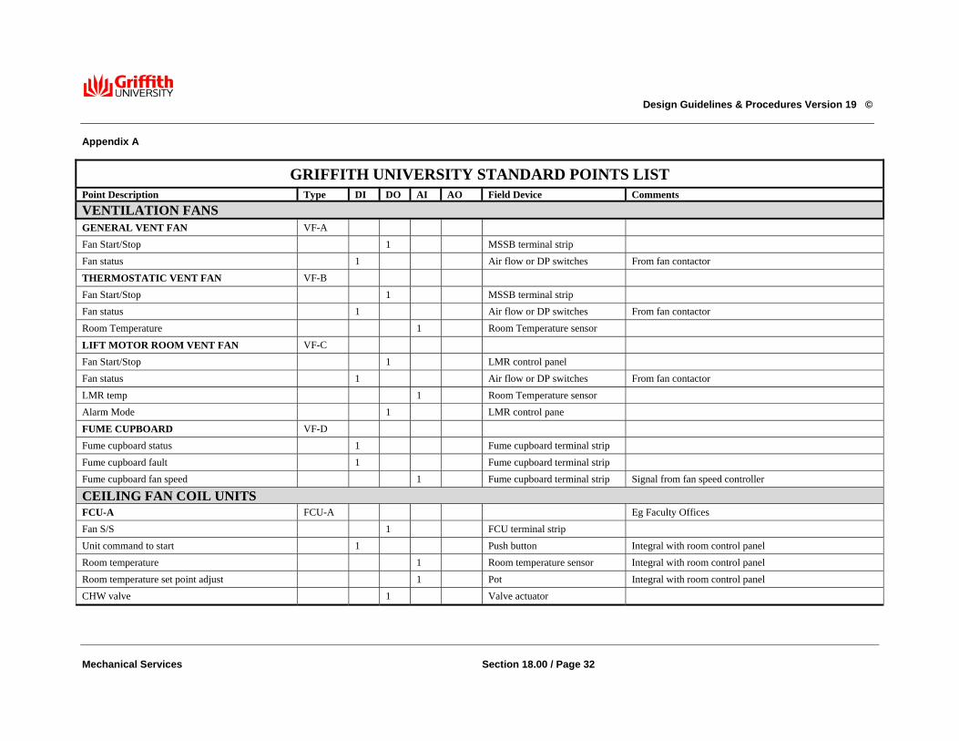
Design Guidelines & Procedures Version 19 ©
Mechanical Services Section 18.00 / Page 32
Appendix A
GRIFFITH UNIVERSITY STANDARD POINTS LIST Point Description Type DI DO AI AO Field Device Comments VENTILATION FANS GENERAL VENT FAN VF-A Fan Start/Stop 1 MSSB terminal strip Fan status 1 Air flow or DP switches From fan contactor
THERMOSTATIC VENT FAN VF-B Fan Start/Stop 1 MSSB terminal strip Fan status 1 Air flow or DP switches From fan contactor Room Temperature 1 Room Temperature sensor
LIFT MOTOR ROOM VENT FAN VF-C Fan Start/Stop 1 LMR control panel Fan status 1 Air flow or DP switches From fan contactor LMR temp 1 Room Temperature sensor Alarm Mode 1 LMR control pane
FUME CUPBOARD VF-D Fume cupboard status 1 Fume cupboard terminal strip Fume cupboard fault 1 Fume cupboard terminal strip Fume cupboard fan speed 1 Fume cupboard terminal strip Signal from fan speed controller
CEILING FAN COIL UNITS FCU-A FCU-A Eg Faculty Offices Fan S/S 1 FCU terminal strip Unit command to start 1 Push button Integral with room control panel Room temperature 1 Room temperature sensor Integral with room control panel Room temperature set point adjust 1 Pot Integral with room control panel CHW valve 1 Valve actuator

Design Guidelines & Procedures Version 19 ©
Mechanical Services Section 18.00 / Page 33
GRIFFITH UNIVERSITY STANDARD POINTS LIST
Point Description Type DI DO AI AO Field Device Comments Heater 1 FCU terminal strip Motion Detector 1 Motion Detector
FCU-B (may be multiple FCU’s) FCU-B Eg General area Fan S/S 1 FCU terminal strip Starts multiple units Room temperature 1 Room temperature sensor CHW valve 1 1 Valve actuator Modulating or on/off Heater 1 FCU terminal strip Controls multiple heaters
FCU-C (may be multiple FCU’s) Eg Seminar Rooms, Labs, Conference Rooms Fan S/S 1 FCU terminal strip Starts multiple units Motion detector 1 Motion detector Motion detectors wired in parallel Room temperature 1 Room temperature sensor CHW valve 1 1 Valve actuator Modulating or on/off Heater 1 FCU terminal strip Controls multiple heaters
FCU-D (may be multiple FCU’s) eg General Offices Fan S/S 1 FCU terminal strip Starts multiple units Command to start outside time schedule 1 Push button Room temperature 1 Room temperature sensor CHW valve 1 1 Valve actuator Modulating or on/off Heater 1 FCU terminal strip Controls multiple heaters
AIR HANDLING UNITS SINGLE ZONE UNIT AHU-A1 Fan Stop/Start 1 MSSB terminal strip
Fan status 1 Air flow or DP switches

Design Guidelines & Procedures Version 19 ©
Mechanical Services Section 18.00 / Page 34
GRIFFITH UNIVERSITY STANDARD POINTS LIST
Point Description Type DI DO AI AO Field Device Comments Command to start outside time schedule 1 Push button Unit operation 1 Light on push button Room temperature 1 Room temp sensor CHW valve 1 Valve actuator Heater N MSSB terminal strip N steps of electrical heating
SINGLE ZONE UNIT AHU-A2 Fan Stop/Start 1 MSSB terminal strip Fan status 1 Air flow or DP switches Motion detector 1 Motion detector Motion detectors wired in parallel Room temperature 1 Room temp sensor CHW valve 1 Valve actuator Heater N MSSB terminal strip N steps of electrical heating
VAV AIR HANDLING UNIT AHU-B Fan Stop/Start 1 MSSB terminal strip Fan status 1 Air flow or DP switches Command to start outside time schedule 1 Push button Unit operation 1 Light on push button Supply air duct temperature 1 Duct temp sensor CHW valve 1 Valve actuator SA duct static pressure 1 SP sensor Locate sensor 2/3rds along duct run VSD control, fault 1 1 VSD
MULTI ZONE-FACE AND BYPASS AHU AHU-C
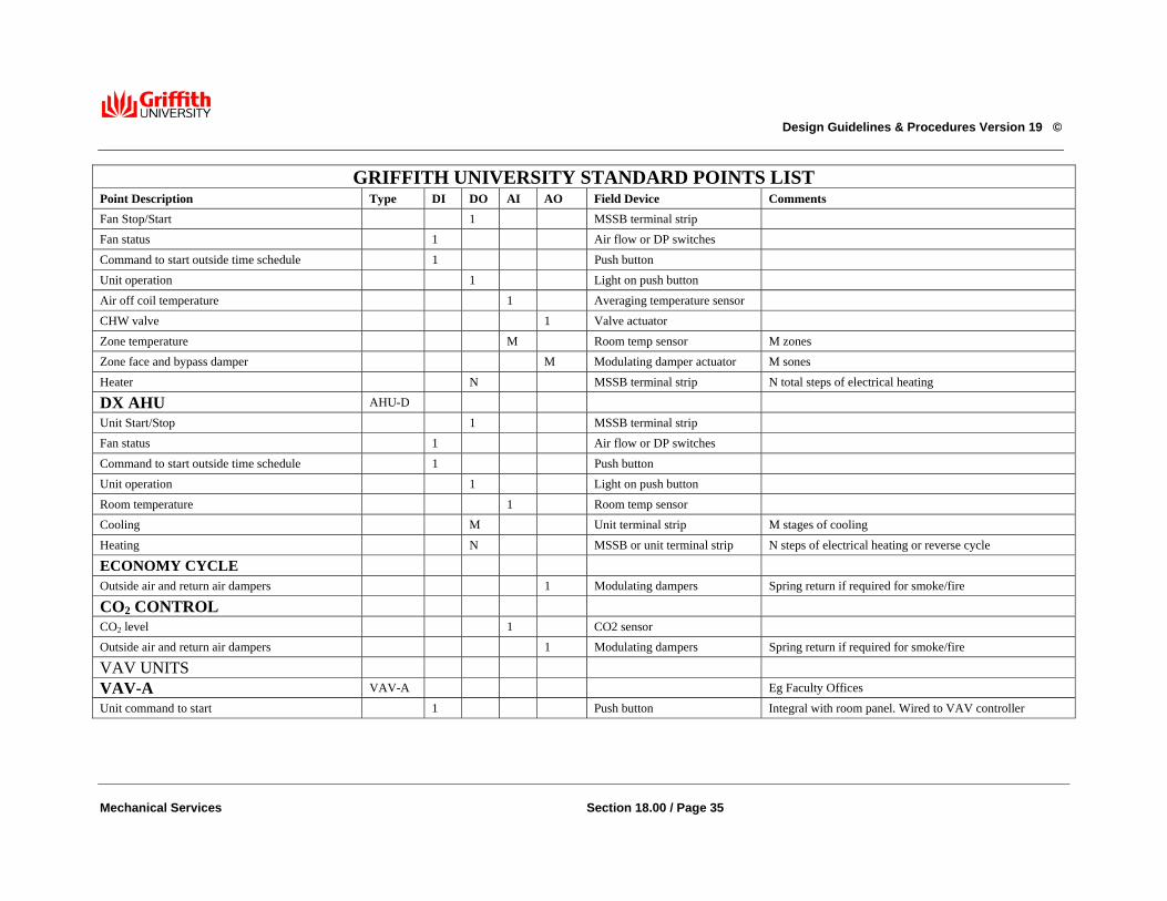
Design Guidelines & Procedures Version 19 ©
Mechanical Services Section 18.00 / Page 35
GRIFFITH UNIVERSITY STANDARD POINTS LIST Point Description Type DI DO AI AO Field Device Comments Fan Stop/Start 1 MSSB terminal strip Fan status 1 Air flow or DP switches Command to start outside time schedule 1 Push button Unit operation 1 Light on push button Air off coil temperature 1 Averaging temperature sensor CHW valve 1 Valve actuator Zone temperature M Room temp sensor M zones Zone face and bypass damper M Modulating damper actuator M sones Heater N MSSB terminal strip N total steps of electrical heating
DX AHU AHU-D Unit Start/Stop 1 MSSB terminal strip Fan status 1 Air flow or DP switches Command to start outside time schedule 1 Push button Unit operation 1 Light on push button Room temperature 1 Room temp sensor Cooling M Unit terminal strip M stages of cooling Heating N MSSB or unit terminal strip N steps of electrical heating or reverse cycle
ECONOMY CYCLE Outside air and return air dampers 1 Modulating dampers Spring return if required for smoke/fire
CO2 CONTROL CO2 level 1 CO2 sensor Outside air and return air dampers 1 Modulating dampers Spring return if required for smoke/fire
VAV UNITS
VAV-A VAV-A Eg Faculty Offices Unit command to start 1 Push button Integral with room panel. Wired to VAV controller

Design Guidelines & Procedures Version 19 ©
Mechanical Services Section 18.00 / Page 36
GRIFFITH UNIVERSITY STANDARD POINTS LIST
Point Description Type DI DO AI AO Field Device Comments Room temperature 1 Room temperature senor Integral with room panel. Wired to VAV controller Room temperature set point adjust 1 Pot Integral with room panel. Wired to VAV controller Primary air velocity 1 Pilot tube Connected to VAV controller VAV damper 1 Damper actuator Integral with VAV controller Heater N VAV controller terminals N steps
VAV-B VAV-B Eg General area Room temperature 1 Room temperature sensor Integral with room panel, wired to VAV controller Primary air velocity 1 Pilot tube Connected to VAV controller VAV damper 1 Damper actuator Integral with VAV controller Heater N VAV controller terminals N Steps
VAV-C VAV-C Eg Seminar Rooms, labs, Conference Rooms Motion detector 1 Motion detector Motion det’s wired in parallel to VAV controller Room temperature 1 Room temperature sensor Wired to VAV controller Primary air velocity 1 Pilot tube Connected to VAV controller VAV damper 1 Damper actuator Integral with VAV controller Heater N VAV controller terminals N Steps
VAV-D VAV-D Eg General Offices
Command to start outside time schedule 1 Push button Wired to VAV controller
Room temperature 1 Room temperature sensor Wired to VAV controller Primary air velocity 1 Pilot tube Connected to VAV controller VAV damper 1 Damper actuator Integral with VAV controller Heater N VAV controller terminals N steps
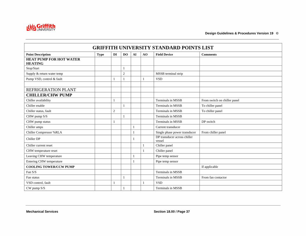
Design Guidelines & Procedures Version 19 ©
Mechanical Services Section 18.00 / Page 37
GRIFFITH UNIVERSITY STANDARD POINTS LIST
Point Description Type DI DO AI AO Field Device Comments HEAT PUMP FOR HOT WATER HEATING
Stop/Start 1 Supply & return water temp 2 MSSB terminal strip Pump VSD, control & fault 1 1 1 VSD
REFRIGERATION PLANT
CHILLER/CHW PUMP Chiller availability 1 Terminals in MSSB From switch on chiller panel Chiller enable 1 Terminals in MSSB To chiller panel Chiller status, fault 2 Terminals in MSSB To chiller panel CHW pump S/S 1 Terminals in MSSB CHW pump status 1 Terminals in MSSB DP switch Chiller amps 1 Current transducer Chiller Compressor %RLA 1 Single phase power transducer From chiller panel
Chiller DP 1 DP transducer across chiller vessel
Chiller current reset 1 Chiller panel CHW temperature reset 1 Chiller panel Leaving CHW temperature 1 Pipe temp sensor Entering CHW temperature 1 Pipe temp sensor
COOLING TOWER/CCW PUMP If applicable Fan S/S Terminals in MSSB Fan status 1 Terminals in MSSB From fan contactor VSD control, fault 1 1 VSD CW pump S/S 1 Terminals in MSSB

Design Guidelines & Procedures Version 19 ©
Mechanical Services Section 18.00 / Page 38
GRIFFITH UNIVERSITY STANDARD POINTS LIST Point Description Type DI DO AI AO Field Device Comments CW pump status 1 Terminals in MSSB DP switch Entering & leaving CW temperatures 2 Pipe temp sensors Assumes one CT per chiller
FOR A PRIMARY ONLY CHW SYSTEM: Control valve in bypass CHW common leaving, return and entering temps 3 Pipe temp sensors Bypass valve(s) 1or2 Valve actuator(s) One output per valve Outside air temperature 1 OA temperature sensor If none already exists Refrigerant leak detector 1 Terminals in MSSB FOR A PRIMARY/SECONDARY CHW SYSTEM: Open pipe bypass
CHW common leaving temperature, before bypass 1 Pipe temp sensor CHW return temperature, before bypass 1 Pipe temp sensor CHW entering temperature, after bypass 1 Pipe temp sensor CHW bypass flow & direction 1 1 Magnetic flow meter Secondary CHW DP 1 DP sensor Locate on index run Outside air temperature 1 OA temperature sensor If none already exists Refrigerant leak detector 1 Terminals in MSSB
SECONDARY CHW PUMP Entering & leaving CHW temperatures 2 Pipe temp sensors SCHW pump S/S 1 Terminals in MSSB VSD control, fault 1 1 VSD SCHW Pump Status 2 Terminals in MSSB DP Switch SCHW DP 1 DP sensor Locate on index run

Design Guidelines & Procedures Version 19 ©
Mechanical Services Section 18.00 / Page 39
GRIFFITH UNIVERSITY STANDARD POINTS LIST Point Description Type DI DO AI AO Field Device Comments
DECOUPLING Entering CHW temperatures before and after bypass 2 Pipe temp sensors
Leaving CHW temperature 1 Pipe temp sensors Bypass flow and direction 1 1 Magnetic flow meter Sized to take full building water flow Mixed Bypass/Supply temp 1 Pipe temp sensors Motorised decoupling valve 1 Valve actuator Motorised decoupling bypass valve 1 Valve actuator Flow meter, bypass & pump supply 2 2 Flow meter Low load motorised bypass 1 Located in building
Throttling valve and position N N Valve actuator N valves Mixed Bypass/Supply temp 1 Pipe temp sensors Motorised decoupling valve 1 Valve actuator Motorised decoupling bypass valve 1 Valve actuator Flow meter, bypass & pump supply 2 2 Flow meter Low load motorised bypass 1 Located in building
MISCELLANEOUS MECHANICAL MSSB common fault 1 Terminals in MSSB One per MSSB MSSB or MSB KWh 1 Terminals in MSSB Fire Alarm 1 Terminals in MSSB One per building
ELECTRICAL MSB KWh 1 Terminals in MSB External lighting control 1 Terminals in DB One per building Corridor lighting control 1 Terminals in DB One per floor

Design Guidelines & Procedures Version 19 ©
Mechanical Services Section 18.00 / Page 40
GRIFFITH UNIVERSITY STANDARD POINTS LIST Point Description Type DI DO AI AO Field Device Comments Foyer lighting control 1 Terminals in DB One per building LIFT LMR Alarm 1 Volt Free Contacts One per LMR
DOMESTIC WATER Cold Water Break Tank Demineralised Water Tank Booster Pump(s) Alarm Hot Water Circulating Pumps Hot Water Heater Elements
2 1 1
1 1
Level Sensors Level Sensors Pressure Switch Terminals in DB Terminals in DB
Overflow and Extra Low level alarm High and Low levels Pump failure and low pressure Control for Load shedding Control for Load shedding
LABORATORY GASES Compressed Air Alarm 1 Volt Free Contact From Air Compressed Control Panel Vacuum Plant Alarm 1 Volt Free Contact From Vacuum Pump Control Panel