184 chapter 3 microprocessor types and...
TRANSCRIPT

184 Chapter 3 Microprocessor Types and Specifications
Figure 3.59 Pentium 4 processor.
The main technical details for the Pentium 4 include
� Speeds range from 1.3GHz to 1.7GHz and beyond.
� 42 million transistors, 0.18-micron process.
� Software compatible with previous Intel 32-bit processors.
� Processor (front-side) bus runs at 400MHz.
� Arithmetic logic units (ALUs) run at twice the processor core frequency.
� Hyper-pipelined (20-stage) technology.
� Very deep out-of-order instruction execution.
� Enhanced branch prediction.
� 20KB L1 cache (12KB L1 execution trace cache plus 8KB L1 data cache).
� 256KB on-die, full-core speed 128-bit L2 cache with eight-way associativity.
� L2 cache can handle up to 4GB RAM and supports ECC.
� SSE2—144 new SSE2 instructions.
� Enhanced floating-point unit.
� Multiple low-power states.
04 0789725428 CH03 8/1/01 3:08 PM Page 184

Intel Pentium 4 (Seventh-Generation) Processors 185
Figure 3.60 Pentium 4 die (0.18-micron process, 42 million transistors). Photograph used by permission ofIntel Corporation.
Intel has abandoned roman numerals for a standard Arabic numeral 4 designation. Internally, thePentium 4 introduces a new architecture Intel calls NetBurst microarchitecture, which includes hyper-pipelined technology, a rapid execution engine, a 400MHz system bus, and an execution trace cache.The hyper-pipelined technology doubles the instruction pipeline depth as compared to the PentiumIII, meaning more and smaller steps are required to execute instructions. However, it also enablesmuch higher clock speeds to be more easily attained. The rapid execution engine enables the twointeger arithmetic logic units (ALUs) to run at twice the processor core frequency, which meansinstructions can execute in 1/2 a clock cycle. The 400MHz system bus is a quad-pumped bus runningoff a 100MHz system clock transferring data four times per clock cycle. The execution trace cache is ahigh-performance Level 1 cache that stores approximately 12k decoded micro-operations. Thisremoves the instruction decoder from the main execution pipeline, increasing performance.
Of these the high-speed processor bus is most notable. Technically speaking, the processor bus is a100MHz quad-pumped bus that transfers four times per cycle (4x), for a 400MHz effective rate.Because the bus is 64 bits (8 bytes) wide, this results in a throughput rate of 3,200MB/sec. Thismatches the speed of the dual-channel RDRAM, which is 1,600MB/sec per channel, or 3,200MB/sectotal. The use of dual-channel RDRAM means that RIMMs must be added in matched pairs. Dualbanks of PC1600 DDR would also match this bandwidth, and that might be an option in the future asnew chipsets arrive.
In the new 20-stage pipelined internal architecture, individual instructions are broken down intomany more sub-stages, making this almost like a RISC processor. Unfortunately, this can add to thenumber of cycles taken to execute instructions if they are not optimized for this processor. Earlybenchmarks running existing software showed that existing Pentium III or AMD Athlon processorscould easily keep pace with or even exceed the Pentium 4 in specific tasks; however, this is changingnow that applications are being recompiled to work smoothly with the Pentium 4’s deep pipelinedarchitecture.
The Intel Pentium 4 also introduces a new CPU socket, more stringent memory configuration, andeven new power supply and case requirements.
The Pentium 4 is the first Intel CPU to use Socket 423, which has 423 pins in a 39x39 SPGA arrange-ment. Voltage selection is made via an automatic voltage regulator module installed on the mother-board and wired to the socket.
Chapter 3
04 0789725428 CH03 8/1/01 3:08 PM Page 185

766 Chapter 13 Optical Storage
DVD-RAM specifications are shown in Table 13.28.
Table 13.28 DVD-RAM Specifications
Storage capacity 2.6GB single-sided; 5.2GB double sided
Disc diameter 80mm–120mm
Disc thickness 1.2mm (0.6mm×2: bonded structure)
Recording method Phase change
Laser wavelength 650nm
Data bit length 0.41–0.43 microns
Recording track pitch 0.74 microns
Track format Wobbled land and groove
DVD-RDVD-R is a write-once medium very similar to CD-R. As such, it is ideal for recording archival data ordistribution discs. DVD-R discs can be played on standard DVD-ROM drives.
DVD-R has a single-sided storage capacity of 3.95GB—about six times that of a CD-R—and doublethat for a double-sided disc. These discs use an organic dye recording layer that allows for a low mate-rial cost, similar to CD-R.
To enable positioning accuracy, DVD-R uses a wobbled groove recording, in which special groovedtracks are pre-engraved on the disc during the manufacturing process. Data is recorded within thegrooves only. The grooved tracks wobble slightly right and left, and the frequency of the wobble con-tains clock data for the drive to read, as well as clock data for the drive. The grooves are spaced moreclosely together than with DVD-RAM, but data is recorded only in the grooves and not on the lands(see Figure 13.15).
Groove trackspacing 0.8microns
Wobble encodedclock markings
Wobble addressmarks
Recordingmark
Figure 13.15 DVD-R wobbled groove recording.
Table 13.29 has the basic specifications for DVD-R drives.
14 0789725428 CH13 8/1/01 2:59 PM Page 766
Recordable DVD Standards 767
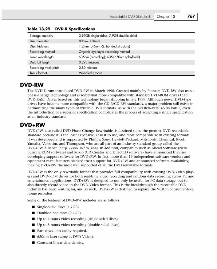
Table 13.29 DVD-R Specifications
Storage capacity 3.95GB single-sided; 7.9GB double-sided
Disc diameter 80mm–120mm
Disc thickness 1.2mm (0.6mm×2: bonded structure)
Recording method Organic dye layer recording method
Laser wavelength 635nm (recording); 635/650nm (playback)
Data bit length 0.293 microns
Recording track pitch 0.80 microns
Track format Wobbled groove
DVD-RWThe DVD Forum introduced DVD-RW in March 1998. Created mainly by Pioneer, DVD-RW also uses aphase-change technology and is somewhat more compatible with standard DVD-ROM drives thanDVD-RAM. Drives based on this technology began shipping in late 1999. Although newer DVD-typedrives have become more compatible with the CD-R/CD-RW standards, a major problem still exists inharmonizing the many types of writable DVD formats. As with the old Beta-versus-VHS battle, eventhe introduction of a superior specification complicates the process of accepting a single specificationas an industry standard.
DVD+RWDVD+RW, also called DVD Phase Change Rewritable, is destined to be the premier DVD recordablestandard because it is the least expensive, easiest to use, and most compatible with existing formats. It was developed and is supported by Philips, Sony, Hewlett-Packard, Mitsubishi Chemical, Ricoh,Yamaha, Verbatim, and Thompson, who are all part of an industry standard group called theDVD+RW Alliance (http://www.dvdrw.com). In addition, companies such as Ahead Software (NeroBurning ROM software) and Roxio (CD Creator and DirectCD software) have announced they aredeveloping support software for DVD+RW. In fact, more than 19 independent software vendors andequipment manufacturers pledged their support for DVD+RW and announced software availability,making DVD+RW the most well supported of all the DVD rewritable formats.
DVD+RW is the only rewritable format that provides full compatibility with existing DVD-Video play-ers and DVD-ROM drives for both real-time video recording and random data recording across PC andentertainment applications. DVD+RW is designed to not only be useful for PC data storage, but toalso directly record video in the DVD-Video format. This is the breakthrough the recordable DVDindustry has been waiting for, and as such, DVD+RW is destined to replace the VCR in consumer-levelhome recorders.
Some of the features of DVD+RW includes are as follows:
� Single-sided discs (4.7GB).
� Double-sided discs (9.4GB).
� Up to 4 hours video recording (single-sided discs).
� Up to 8 hours video recording (double-sided discs).
� Bare discs—no caddy required.
� 650nm laser (same as DVD-Video).
� Constant linear data density.
Chapter 13
14 0789725428 CH13 8/1/01 2:59 PM Page 767
842 Chapter 15 Video Hardware
the software running on your system. The software that makes calls to the video BIOS can be a stand-alone application, an operating system, or the main system BIOS. The programming in the BIOS chipenables your system to display information on the monitor during the system POST and bootsequences, before any other software drivers have been loaded from disk.
√√ See “BIOS Basics,” p. 346.
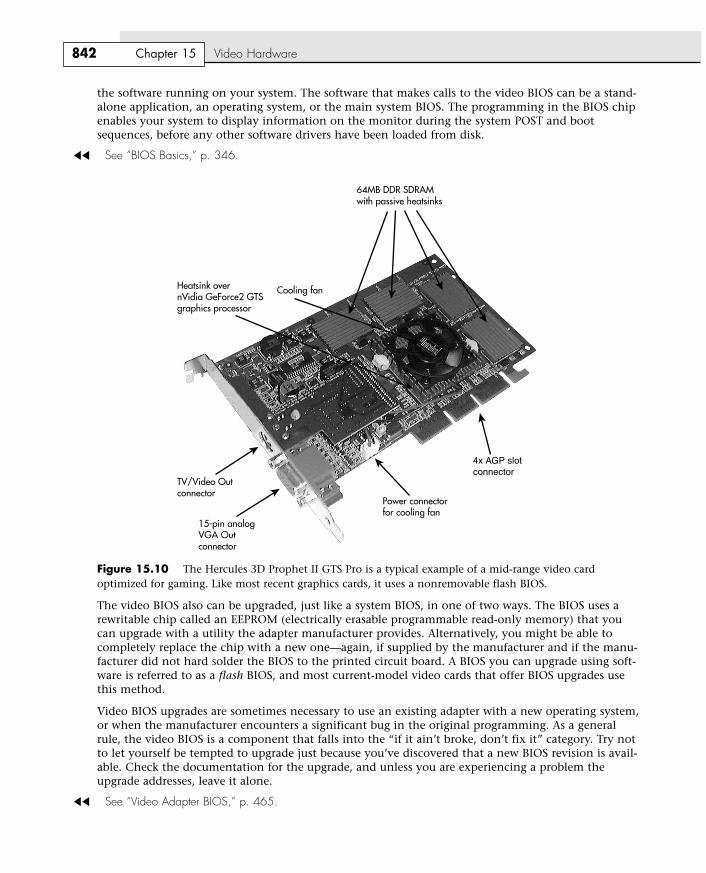
64MB DDR SDRAM with passive heatsinks
Cooling fanHeatsink over nVidia GeForce2 GTS graphics processor
TV/Video Out connector
15-pin analog VGA Out connector
Power connector for cooling fan
4x AGP slot connector
Figure 15.10 The Hercules 3D Prophet II GTS Pro is a typical example of a mid-range video card optimized for gaming. Like most recent graphics cards, it uses a nonremovable flash BIOS.
The video BIOS also can be upgraded, just like a system BIOS, in one of two ways. The BIOS uses arewritable chip called an EEPROM (electrically erasable programmable read-only memory) that youcan upgrade with a utility the adapter manufacturer provides. Alternatively, you might be able tocompletely replace the chip with a new one—again, if supplied by the manufacturer and if the manu-facturer did not hard solder the BIOS to the printed circuit board. A BIOS you can upgrade using soft-ware is referred to as a flash BIOS, and most current-model video cards that offer BIOS upgrades usethis method.
Video BIOS upgrades are sometimes necessary to use an existing adapter with a new operating system,or when the manufacturer encounters a significant bug in the original programming. As a generalrule, the video BIOS is a component that falls into the “if it ain’t broke, don’t fix it” category. Try notto let yourself be tempted to upgrade just because you’ve discovered that a new BIOS revision is avail-able. Check the documentation for the upgrade, and unless you are experiencing a problem theupgrade addresses, leave it alone.
√√ See “Video Adapter BIOS,” p. 465.
16 0789725428 CH15 8/1/01 3:13 PM Page 842

Video Display Adapters 843
The Video ProcessorThe video processor, or chipset, is the heart of any video adapter and essentially defines the card’sfunctions and performance levels. Two video adapters built using the same chipset often have manyof the same capabilities and deliver comparable performance. Also, the software drivers that operatingsystems and applications use to address the video adapter hardware are written primarily with thechipset in mind. You often can use a driver intended for an adapter with a particular chipset on anyother adapter using the same chipset. Of course, cards built using the same chipset can differ in theamount and type of memory installed, so performance can vary.
Several main types of processors are used in video adapters:
� Frame buffer controllers
� Coprocessors
� Accelerators
� 3D graphics processors
Table 15.6 compares these technologies.
Table 15.6 Video Processor Technologies
Processor Where Video Relative RelativeType Processing Takes Place Speed Cost How Used Today
Frame-buffer Computer’s CPU Very slow Very low Obsolete; mostly ISA video cards
Graphics Video card’s own processor Very fast Very high CAD and engineering coprocessor workstations
Graphics Video chip draws lines, circles, Fast Low to moderate All mainstream viedo cardsaccelerator shapes; CPU sends commands
to draw them
3D graphics Video cards 3D graphics Fast 2D and Most price ranges All gaming optimized video processor processing unit (in accelerator 3D display depending on cards and most mainstream
chipset) renders polygons, adds chipset, memory, video cardslighting and shading effects as and RAMDAC needed speed
Integrated Video/Motherboard ChipsetsAlthough built-in video has been a staple of low-cost computing for a number of years, until recentlymost motherboard-based video simply moved the standard video components discussed earlier in thischapter to the motherboard. Many low-cost systems—especially those using the semiproprietary LPXmotherboard form factor—have incorporated standard VGA-type video circuits on the motherboard.The performance and features of the built-in video differed only slightly from add-on cards using thesame or similar chipsets, and in most cases the built-in video could be replaced by adding a videocard. Some motherboard-based video also had provisions for memory upgrades.
√√ See “LPX,” p. 201.
However, in recent years the move toward increasing integration on the motherboard has led to thedevelopment of chipsets that include 3D accelerated video and audio support as part of the chipsetdesign. In effect, the motherboard chipset takes the place of most of the video-card components listed
Chapter 15
16 0789725428 CH15 8/1/01 3:13 PM Page 843

886 Chapter 16 Audio Hardware
Connectors for Advanced FeaturesMany of the newest sound cards are designed for advanced gaming, DVD audio playback, and soundproduction uses and have additional connectors to support these uses, such as
� MIDI in and MIDI out. Some advanced sound cards don’t require you to convert the game port(joystick port) to MIDI interfacing by offering these ports on a separate external connector. Thispermits you to use a joystick and have an external MIDI device connected at the same time.Typical location: external device.
� SPDIF (also called SP/DIF) in and SPDIF out. The Sony/Philips Digital Interface receives digitalaudio signals directly from compatible devices without converting them to analog format first.Typical location: external device. SPDIF interfaces are also referred to by some vendors as“Dolby Digital” interfaces.
NoteSPDIF connectors use cables with the standard RCA jack connector but are designed to work specifically at an impedanceof 75ohms—the same as composite video cables. Thus, you can use RCA-jack composite video cables with your SPDIFconnectors. Although audio cables are also equipped with RCA jacks, their impedance is different, making them a lessdesirable choice.
� CD SPDIF. Connects compatible CD-ROM drives with SPDIF interfacing to the digital input ofthe sound card. Typical location: side of audio card.
� TAD in. Connects internal modems with Telephone Answering Device support to the soundcard for sound processing of voice messages. Typical location: side of audio card.
� Digital DIN out. This supports multispeaker digital speaker systems, such as those produced byCambridge for use with the SoundBlaster Live! series. Typical location: external device.
� Aux in. Provides input for other sound sources, such as a TV tuner card. Typical location: side ofaudio card.
� I2S in. This enables the sound card to accept digital audio input from an external source, suchas two-channel decoded AC-3 from DVD decoders and MPEG-2 Zoom Video. Typical location:side of audio card.
Sometimes, these additional connectors are found on the card itself, or sometimes they are attachedto an external breakout box or daughtercard. For example, the Sound Blaster Live! Platinum 5.1 is atwo-piece unit. The audio adapter itself plugs into a PCI slot, but some additional connectors arerouted to a breakout box called the LiveDrive IR, which fits into an unused drive bay, as seen inFigure 16.2.
Figure 16.3 shows a Voyetra Turtle Beach’s Santa Cruz audio adapter card with the internal connectorscommon on today’s 3D sound cards.
Volume ControlSome older audio adapters include a thumbwheel volume control next to the input/output jacks,although sophisticated sound cards have no room for it. This control is usually redundant because theoperating system or the software included with the adapter typically provides a combination of keysor a visual slider control you can use to adjust the volume. In fact, the volume wheel can be trouble-some; if you aren’t aware of its existence and it is turned all the way down, you might be puzzled bythe adapter’s failure to produce sufficient sound.
17 0789725428 CH16 8/1/01 2:58 PM Page 886

Audio Adapter Features 887
Figure 16.2 The Sound Blaster Live! Platinum 5.1 comes with the LiveDrive IR to support its many features.
Chapter 16
Digitalout
MIDIin
Line inwithvolumecontrol
Optical in
Optical out
Frontlineout
Rearlineout
SPDIFout
SPDIFin
Line in
Headphoneout withvolumecontrol
Left Aux in
Right Aux in IR window for remote control
Microphonein
Game port
MIDIout
VersaJack—Yellow 1/8" stereomini phone jack may be used as ananalog line or headphones output, digital output, or analogline input. All functionsaccessible from the Santa CruzControl Panel application.
Mic in
Line in
Gameport/MIDI
Upgradeoptionheader
TADconnector
CD audioconnector
Aux inputconnector
CD-ROM S/PDIFdigital input connector
Front speakers
Back speakers
Wavetable Header—Allows addition of hardware wavetable daughtercards for MIDI output such as the Turtle Beach Cancun FX.
Crystal/Cirrus Logic CS4630features audio processing,SoundFusion® DSP, and DSP-enhanced wavetableMIDI synthesizer circuitry.
Figure 16.3 Voyetra Turtle Beach’s Santa Cruz is a typical example of an advanced 3D sound card.
17 0789725428 CH16 8/1/01 2:58 PM Page 887
1066 Chapter 20 Local Area Networking
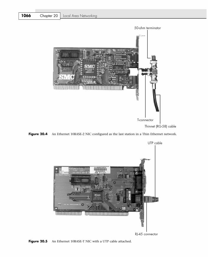
Figure 20.4 An Ethernet 10BASE-2 NIC configured as the last station in a Thin Ethernet network.
Figure 20.5 An Ethernet 10BASE-T NIC with a UTP cable attached.
T-connector
Thinnet (RG-58) cable
50-ohm terminator
UTP cable
RJ-45 connector
21 0789725428 CH20 8/1/01 2:47 PM Page 1066

Hardware Elements of Your Network 1067
Virtually all standard and Fast Ethernet NICs made for client-PC use on the market today are designedto support twisted-pair cable exclusively. If you are adding a client PC to an existing network that usessome form of coaxial cable, you have three options:
� Purchase a combo NIC that supports coaxial cable as well as RJ-45 twisted-pair cabling.
� Purchase a media converter that can be attached to the coaxial cable to allow the newer UTP-based NICs to connect to the existing network.
� Use a switch or hub that has both coaxial cable and RJ-45 ports. A dual-speed (10/100) device isneeded if you are adding one or more Fast Ethernet clients.
Network CablesFor maximum economy, NICs and network cables must match, although media converters can beused to interconnect networks based on the same standard, but using different cable.
Thick and Thin Ethernet Coaxial CableThe first versions of Ethernet were based on coaxial cable. The original form of Ethernet, 10BASE-5,used a thick coaxial cable (called Thicknet) that was not directly attached to the NIC. A device calledan attachment unit interface (AUI) ran from a DB15 connector on the rear of the NIC to the cable.The cable had a hole drilled into it to allow the “vampire tap” to be connected to the cable. NICsdesigned for use with thick Ethernet cable are almost impossible to find as new hardware today.
10BASE-2 Ethernet cards use a BNC (Bayonet-Neill-Concilman) connector on the rear of the NIC.Although the thin coaxial cable (called Thinnet or RG-58) used with 10BASE-2 Ethernet has a bayonetconnector that can physically attach to the BNC connector on the card, this configuration is incorrectand won’t work. Instead, a BNC T-connector attaches to the rear of the card, allowing a thin Ethernetcable to be connected to either both ends of the T (for a computer in the middle of the network) or toone end only (for a computer at the end of the network). A 50 ohm terminator is connected to theother arm of the T to indicate the end of the network and prevent erroneous signals from being sentto other clients on the network. Combo cards with both BNC and RJ-45 connectors are still availablebut can run at only standard Ethernet speeds.
Figure 20.6 shows an Ethernet BNC coaxial T-connector, and Figure 20.7 illustrates the design of coaxial cable.
Chapter 20
Wire jacket Shield Insulation Conductor
Figure 20.6 An Ethernet coaxial cable T-connector.
Figure 20.7 Coaxial cable.
21 0789725428 CH20 8/1/01 2:47 PM Page 1067