1882 ieee transactions on antennas and propagation, … · 1884 ieee transactions on antennas and...
TRANSCRIPT

1882 IEEE TRANSACTIONS ON ANTENNAS AND PROPAGATION, VOL. 56, NO. 7, JULY 2008
Naval Structural Antenna Systems for Broadband HFCommunications—Part III: Experimental
Evaluation on Scaled PrototypesLorenzo Mattioni, Domenico Di Lanzo, and Gaetano Marrocco, Member, IEEE
Abstract—We describe the design, fabrication and measure-ment of reduced-size prototypes of the Naval Structural Antenna,recently proposed as a compact and multifunction solution tobroadband naval communications. The original broadband HFsub-radiator, loaded by lumped impedances, is scaled down to theVHF/UHF ranges and re-designed in planar technology in orderto simplify and to automate the fabrication process. Measurementon single-port and 4-port antennas, in which the central structureresembles a naval funnel and a big mast, have shown a goodagreement with the simulations.
Index Terms—Broadband antennas, HF antennas, multiport an-tennas, shipborne antennas, software defined radio.
I. INTRODUCTION
THIS work completes a set of papers on new broadband andreconfigurable structural antenna systems, which were
recently introduced by the authors [1], [2] in the Naval SoftwareDefined Radio context [3]. Actual naval systems employ eitherbroadband antennas together with combining networks, or amultiplicity of narrow-band radiating elements. In the first case,the resulting system efficiency may be highly reduced by thelosses of the power combiners. In the other case, the coexistenceof several radiators increases the interference with receivers,causing co-location problems, and requires large spaces andcomplicated feeding networks onboard the ship. These issuesare particularly critical in the HF band (2 MHz–30 MHz) be-cause of the large wavelengths involved. The Naval StructuralAntenna System (NSA) promises to be a possible solutionto part of these drawbacks. The structure is obtained fromthe integration of multiple loaded wires (sub-radiators) [4]together with an existing ship-superstructure, for instance afunnel (Fig. 1) or a big mast. The resulting multiport antennaexhibits a very compact layout and offers a great flexibility interms of power handling and pattern reconfigurability. In partic-ular, the NSA permits to highly improve the system efficiencywith respect to the traditional broadband antennas equipped
Manuscript received July 24, 2007; revised February 5, 2008. Published July7, 2008 (projected). This work was supported in part by Selex Communications,A Finmeccanica Company, Italy.
L. Mattioni was with the Dipartimento di Informatica, Sistemi e Produzione,University of Roma “Tor Vergata”, Rome-00133, Italy. He is now with IDSS.p.A., Rome-00189, Italy
D. Di Lanzo was with the Dipartimento di Informatica, Sistemi e Produzione,University of Roma “Tor Vergata”, Rome-00133, Italy. He is now with SpaceEngineering S.p.A., Rome-00155, Italy.
G. Marrocco is with the Dipartimento di Informatica, Sistemi e Produzione,University of Roma “Tor Vergata”, Rome-00133, Italy (e-mail: [email protected]).
Digital Object Identifier 10.1109/TAP.2008.924711
Fig. 1. HF-NSA obtained from a funnel-like structure. The four input ports atthe base of each sub-radiator are clockwise numbered.
with lossy combining networks, and to moderately shape thebeam. These performances can be achieved provided that theinter-port coupling is low enough to preserve port matching inthe whole band and nearly omnidirectional radiation patternson the horizontal plane. While the previous papers concerningthe NSA discussed the basic ideas, the performances on aninfinite perfect ground plane [1], and the design methodologyon real naval platforms [2], this contribution experimentallydemonstrates the concept and verifies the main electromagneticfeatures by characterization and fabrication of NSA scaledprototypes. Two NSA models, resembling a funnel and a bigmast, are considered here. The optimization of the loads isperformed by a genetic algorithm [5], [6], and the sub-radiatorsare manufactured by printing a metallic trace on a thin dielectricsubstrate. Simplifications of the NSA geometry, of the loadstopology and position on the wires, and the use of a planartechnology permit to minimize the fabrication inaccuracies.
The antenna input electric parameters and near field radiationare measured by an ad-hoc procedure accounting for port peri-odicity, and compared with numerical models.
II. PROTOTYPE DESIGN AND FABRICATION
Following the layouts in [1], [2], two different geometries areconsidered here for the central body. The first one is a cylin-drical funnel-like structure having about the same height as the
0018-926X/$25.00 © 2008 IEEE
MATTIONI et al.: NAVAL STRUCTURAL ANTENNA SYSTEMS FOR BROADBAND HF COMMUNICATIONS 1883
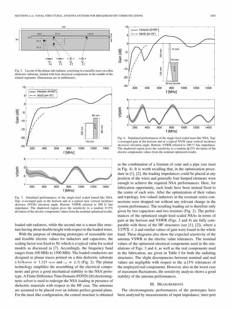
Fig. 2. Layout of the planar sub-radiator, consisting in a metallic trace on a thindielectric substrate, loaded with four electrical components in the middle of therelated segments. Dimensions are in millimeters.
Fig. 3. Simulated performances of the single-feed scaled funnel-like NSA.Top: �-averaged gain at the horizon and at a typical near vertical incidenceskywave (NVIS) elevation angle. Bottom: VSWR referred to 200 � lineimpedance. The shadowed region gives the sensitivity to a random �15%deviation of the electric components values from the nominal optimized results.
loaded sub-radiators, while the second one is a mast-like struc-ture having about double height with respect to the loaded wires.
With the purpose of obtaining prototypes of reasonable sizeand feasible electric values for inductors and capacitors, thescaling factor was fixed to 50, which is a typical value for scaledmodels as discussed in [7]. Accordingly, the frequency bandranges from 100 MHz to 1500 MHz. The loaded conductors aredesigned as planar traces printed on a thin dielectric substrate( and ) (Fig. 2). The planartechnology simplifies the assembling of the electrical compo-nents and gives a good mechanical stability to the NSA proto-type. A Finite Difference Time Domain (FDTD) [8] electromag-netic solver is used to redesign the NSA loading in presence ofdielectric materials with respect to the HF case. The antennasare assumed to be placed over an infinite perfect ground plane.For the mast-like configuration, the central structure is obtained
Fig. 4. Simulated performances of the single-feed scaled mast-like NSA. Top:�-averaged gain at the horizon and at a typical NVIS (near vertical incidenceskywave) elevation angle. Bottom: VSWR referred to 200 � line impedance.The shadowed region gives the sensitivity to a random �15% deviation of theelectric components values from the nominal optimized results.
as the combination of a frustum of cone and a pipe (see insetin Fig. 4). It is worth recalling that, in the optimization proce-dure in [1], [2], the loading impedances could be placed at anyposition of the wires and generally four lumped elements wereenough to achieve the required NSA performances. Here, forfabrication opportunity, such loads have been instead fixed tothe centre of each wire. After the optimization of their valuesand topology, low-valued inductors in the resonant series-con-nections were dropped out without any relevant change in thesystem performance. The resulting loading set is therefore onlygiven by two capacitors and two resistors (Fig. 2). The perfor-mances of the optimized single-feed scaled NSAs in terms ofgain at the horizon and VSWR (Figs. 3 and 4) are fully com-parable with those of the HF structures (see [1], [2]), where a
and similar values of gain were found in the wholeband. These diagrams also show the expected sensitivity of theantenna VSWR to the electric value tolerances. The nominalvalues of the optimized electrical components used in the sim-ulations of Figs. 3 and 4, as well as the real components usedin the fabrication, are given in Table I for both the radiatingstructures. The slight discrepancies between nominal and realvalues are negligible with respect to the 15% tolerances ofthe employed real components. However, also in the worst caseof maximum fluctuations, the sensitivity analysis shows a goodstability of the antenna performances.
III. MEASUREMENTS
The electromagnetic performances of the prototypes havebeen analyzed by measurements of input impedance, inter-port
1884 IEEE TRANSACTIONS ON ANTENNAS AND PROPAGATION, VOL. 56, NO. 7, JULY 2008
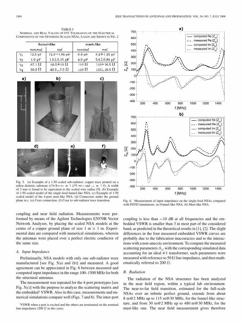
TABLE INOMINAL AND REAL VALUES (�15% TOLERANCE) OF THE ELECTRICAL
COMPONENTS OF THE OPTIMIZED SCALED NSAs. LOADS ARE SHOWN IN FIG. 2
Fig. 5. (a) Example of a 1:50 scaled sub-radiator: copper trace printed on ateflon dieletric substrate (��������� ��� �� and � �� ). A widthof 3 mm is found to be equivalent to the scaled wire radius [9]. (b) Exampleof 1:50 scaled model of the single-feed funnel-like NSA. (c) Example of 1:50scaled model of the 4-port mast-like NSA. (d) Connectors under the groundplane in c. (e) Coax connection. (f) Coax to sub-radiator trace transition.
coupling and near field radiation. Measurements were per-formed by means of the Agilent Technologies E5070B VectorNetwork Analyzer, by placing the scaled NSA models at thecentre of a copper ground plane of size 1 m 1 m. Experi-mental data are compared with numerical simulations, whereinthe antennas were placed over a perfect electric conductor ofthe same size.
A. Input Impedance
Preliminarily, NSA models with only one sub-radiator weremanufactured [see Fig. 5(a) and (b)] and measured. A goodagreement can be appreciated in Fig. 6 between measured andcomputed input impedance in the range 100–1500 MHz for boththe structural antennas.
The measurement was repeated for the 4-port prototypes [seeFig. 5(c)] with the purpose to analyze the scattering matrix andthe embedded1 VSWR. Also in this case, measurements and nu-merical simulations compare well (Figs. 7 and 8). The inter-port
1VSWR when a port is excited and the others are terminated on the nominalline-impedance (200 � in this case).
Fig. 6. Measurement of input impedance on the single-feed NSAs comparedwith FDTD simulations. (a) Funnel-like NSA. (b) Mast-like NSA.
coupling is less than 10 dB at all frequencies and the em-bedded VSWR is smaller than 3 in most part of the consideredband, as predicted in the theoretical results in [1], [2]. The slightdifferences in the four measured embedded VSWR curves areprobably due to the fabrication inaccuracies and to the interac-tions with a non-anecoic environment. To compare the measuredscattering parameters with the corresponding simulated dataaccounting for an ideal 4:1 transformer, such parameters weremeasured with reference to 50 line impedance, and then math-ematically referred to 200 .
B. Radiation
The radiation of the NSA structures has been analyzedin the near field region, within a typical lab environment.The near-to-far field transition, estimated for the full-scaleNSAs over an infinite perfect ground, extends from about8 m@2 MHz up to 115 m@30 MHz, for the funnel-like struc-ture, and from 30 m@2 MHz up to 480 m@30 MHz, for themast-like one. The near field measurement gives therefore

MATTIONI et al.: NAVAL STRUCTURAL ANTENNA SYSTEMS FOR BROADBAND HF COMMUNICATIONS 1885
Fig. 7. Measurement of the scattering parameters on the 4-port NSAs com-pared with FDTD simulations. (a) Funnel-like NSA. (b) Mast-like NSA. In bothcases � � � due to the symmetry of the structures. Data are referred to a200 � line impedance and ports are numbered as in Fig. 1.
Fig. 8. Measurement of the embedded VSWRs on the 4-port NSAs (grey lines)compared with FDTD simulation (black line). (a) Funnel-like NSA. (b) Mast-like NSA. Data are referred to a 200 � line impedance.
useful information about the compliance of the transmitterswith the field exposure limitations onboard the ship, and about
Fig. 9. (a) Scheme for the near field measurement using a short monopole,placed in two different positions (� and � ). (b) Estimation of the antennaradiation in five different directions in the half horizontal plane (eight directionsall around the NSA); the vectors (c), (b), (e) are rotated and translated to becentred in the port 1.
the cohabitation with other onboard equipments. The measure-ment procedure considers the NSA radiation from a single portwhen the others are terminated to a 200 line impedance. Thefield probe is a short monopole of height , which issmaller than in the whole considered band. The monopoleis placed at a fixed radial distance from the NSAgeometrical centre in two different positions ,as shown in Fig. 9(a). During the measurement, the groundplane was locally extended all around the probe to minimizethe diffractions from the metallic edges. The near field data onthe horizontal plane are retrieved from the measurements ofthe mutual coupling , between the th sourced port of theNSA and the probe, which receives the vertical component ofthe radiated field . The strength of at the position of theprobe is given by [10]
(1)
where is the antenna factor of the monopole and isthe magnitude of the voltage drop at the receiver load . As de-scribed in [11], the antenna factor of a monopole is

1886 IEEE TRANSACTIONS ON ANTENNAS AND PROPAGATION, VOL. 56, NO. 7, JULY 2008
Fig. 10. Measurement of the near field radiation on the horizontal plane for the funnel-like NSA, compared with FDTD simulations on an infinite perfect ground,along five different directions. Dashed line indicates the simulated far-field evaluated at a distance � from the NSA. In all the cases port 1 is sourced with � �
� � and the other ports are terminated on 200 �.
Fig. 11. Measurement of the near field radiation on the horizontal plane for the mat-like NSA, compared with FDTD simulations on an infinite perfect ground,along five different directions. Dashed line indicates the simulated far-field evaluated at a distance � from the NSA. In all the cases port 1 is sourced with � �
� � and the other ports are terminated on 200 �.
, where , is the monopoleinput impedance, and is its effective height [10].The power delivered to the receiver is re-lated to the input power at the th transmitting antenna portby . By combining these relations to express
, (1) becomes
(2)
The rotational symmetry among the NSA ports permits to esti-mate the radiation on the horizontal plane along some directionsby a small set of measurements. In a first set-up, the probe isplaced in position [see Fig. 9(a)] and the scattering parame-ters , and are measured. Then the probe is moved inposition and and are obtained. By taking advantageof the port periodicity, the five previous measurements can beeasily referred to a single port, e.g., port 1, as shown in Fig. 9(b),where , and are the positions of three observation
points on the circumference of radius (about20 m for the full-scale antenna). In this way the antenna ra-diation is estimated at five angularly equispaced directions, bymeans of just two set of measurements. It is worth noticing that,for the full-size scale funnel-like configuration, the observationpoints on the circumference are in the far field zone about inthe range 2–6 MHz (100–300 MHz for the scaled configura-tion). For the mast-like configuration, instead, the observationpoints are in the near field zone in the whole considered fre-quency range. Figs. 10 and 11 compare the measurements withthe computed near field around the NSAs for inputpower at port 1. The same diagrams also show the field am-plitude evaluated at the measurement points starting from thecomputed far field radiation function, e.g.
with , . A good agreementis observed between the estimated and computed near field inthe whole band, particularly in positions and , where theprobe is closer to the sourced port and, thus, the coupling with

MATTIONI et al.: NAVAL STRUCTURAL ANTENNA SYSTEMS FOR BROADBAND HF COMMUNICATIONS 1887
the surrounding environment is less effective. Equation (2) givesa useful information about the near field strength onboard a ship(at a distance of about 20 m from the NSA). For instance, fortypical input power, the near field curves inFig. 10 and Fig. 11 have to be increased by 30 dB and a fre-quency-averaged value of about 45–50 dBV/m is found in thevarious observation points.
The comparison between the near field and far field curvesshows a similar behavior in the considered frequency band. Inparticular, in the range 100–300 MHz for the funnel-like config-uration (Fig. 10), the probes are in the far field zone and, there-fore, the performed near field measurement can be considereda good indicator of the far-field antenna radiation. In this case,the measurements also seem to corroborate the azimuthal omni-directionality of the embedded NSA radiation found in [1], [2],with maximum fluctuations of less than 10 dB.
In the rest of the band of the funnel-like configuration andfor the mast-like structure (Fig. 11), the smooth behavior of thefar-field expected from a broadband antenna, is also found in thenear field curves that exhibit small variations with the frequency.In conclusion, near-field measurements, easily to carry out fromcoupling measurements, can also give a first indication of theNSA far field radiation.
IV. CONCLUSIONS
Despite the fabrication inaccuracies, the non-ideality of theelectrical components, and the use of a non-anecoic measure-ment environment, the experimental evaluation of 1:50 scaledNSA models has verifed the main electromagnetic features ofthe radiating system. In particular, the input impedance, the scat-tering parameters and the embedded radiation have shown agood agreement with simulations in the whole 100–1500 MHzband. The NSA technology is now ready to be tested onboardreal naval platforms, although additional problems could arisein the full-scale NSA, due to unwanted parasitic capacities, tohigh power dissipation in the resistors and to the fabrication ofa broadband impedance transformer.
ACKNOWLEDGMENT
The authors wish to thank the Software Radio team ofG. Falcione from Selex Communications, A FinmeccanicaCompany, Italy, for inspiration, funding and technical support,and Prof. P. Tognolatti for suggestions and helpful discussions.
REFERENCES
[1] G. Marrocco and L. Mattioni, “Naval structural antenna systems forbroadband HF communications,” IEEE Trans. Antennas Propag., vol.54, no. 4, pp. 1065–1073, Apr. 2006.
[2] G. Marrocco, L. Mattioni, and V. Martorelli, “Naval structural antennasystems for broadband HF communications—Part II: Design method-ology for real Naval platforms,” IEEE Trans. Antennas Propag., vol.54, no. 11, pp. 3330–3337, Nov. 2006.
[3] J. Mitola, “The software radio architecture,” IEEE Commun. Mag., vol.33, no. 5, pp. 26–38, May 1995.
[4] L. Mattioni and G. Marrocco, “Design of a broad-band HF antenna formultimode Naval communications,” IEEE Antennas Wireless Propag.Lett., vol. 4, pp. 179–182, 2005.
[5] A. Boag, A. Boag, E. Michielssen, and R. Mittra, “Design of electri-cally loaded wire antennas using genetic algorithms,” IEEE Trans. An-tennas Propag., vol. 44, pp. 687–695, May 1996.
[6] L. Mattioni and G. Marrocco, “BLADE: A broadband loaded antennasdesigner,” IEEE Antennas Propag. Mag., vol. 48, no. 5, pp. 120–129,Oct. 2006.
[7] S. R. Best, “On the use of scale brass models in HF shipboard commu-nication antenna design,” IEEE Antennas Propag. Mag., vol. 44, pp.12–22, Apr. 2002.
[8] A. Taflove, Advances in Computational Electrodynamics: The Fi-nite-Difference Time-Domain Method. Norwood, MA: ArtechHouse, 1998.
[9] C. A. Balanis, Antenna Theory: Analysis and Design, 2nd ed. NewYork: Wiley, 1997, ch. 9, p. 456.
[10] T. Macnamara, Handbook of Antennas for EMC. Boston, MA:Artech House, 1995, ch. 4, pp. 253–260, pp.112.
[11] J. H. Kim and J. Il Park, “Development of standard monopole antennafor antenna factor measurement,” in Proc. Int. Symp. on Electromag-netic Compatibility, May 21–23, 1997, pp. 134–137.
Lorenzo Mattioni received the Laurea in Telecom-munications Engineering and the Ph.D. degree inelectromagnetics from the University of Rome “TorVergata,” Italy, in 2004 and 2008, respectively.
Dr. Mattioni is currently working at IDS, S.p.A.,Rome, Italy. His main scientific interests are themodeling and design of innovative broadband an-tenna systems for mobile platforms and for softwaredefined radio technology. Other scientific interestsconcern the design of compact multiband antennasfor mobile devices, the modeling and analysis of
co-located antenna systems in complex electromagnetic environments, andthe design of miniaturized/low-profile antennas for RFID systems. He isthe coauthor of two international patents on broadband multifunction navalantennas.
Domenico Di Lanzo received the Laurea inTelecommunications Engineering from the Univer-sity of Rome “Tor Vergata,” Italy, in 2007.
His main scientific activity concerns the designof broadband antenna systems for software definedradio technology. He is currently working on themodeling and design of reflector antenna systems,horn antennas and microwave components forsatellite applications at Space Engineering S.p.A.,Rome, Italy.
Gaetano Marrocco (M’98) received the Laureain Electronic Engineering and the Ph.D. degree inapplied electromagnetics from the University ofL’Aquila, Italy, in 1994 and 1998, respectively.
Since 1997, he has been a Researcher at the Uni-versity of Rome “Tor Vergata,” Rome, where he cur-rently teaches Antenna Design and Bioelectromag-netics. In summer 1994, he was at the University ofIllinois at Urbana–Champain as a Postgraduate Stu-dent. In autumn 1999, he was a Visiting Researcherat the Imperial College, London, U.K. His research is
mainly directed to the modelling and design of broad band and ultrawidebandantennas and arrays as well as of miniaturized antennas for RFID applications.He has been involved in several space, avionic and naval programs of the Eu-ropean Space Agency, NATO, Italian Space Agency, and the Italian Navy. Heholds two patents on broadband naval antennas and one patent on sensor RFIDsystems.
Prof. Marrocco currently serves as Associate Editor of the IEEE ANTENNAS
AND WIRELESS PROPAGATION LETTERS.