(19) united states (12) patent application publication (10 ... i/0525 (2006.01) (52) u.s. cl. cpc....
TRANSCRIPT

(19) United States US 20140308570A1
(12) Patent Application Publication (10) Pub. No.: US 2014/0308570 A1 Gaben et al. (43) Pub. Date: Oct. 16, 2014
(54) METHOD FOR THE PRODUCTION OF THIN-FILMILITHIUM-ON MICROBATTERIES AND RESULTING MICROBATTERIES
(71) Applicant: I-TEN, Champagne-Au-Mont-D'Or (FR)
(72) Inventors: Fabien Gaben, Ecully (FR); Frédéric Bouyer, Perrigny Les Dijon (FR); Bruno Vuillemin, Darbonnay (FR)
(21) Appl. No.: 14/355,170
(22) PCT Filed: Oct. 30, 2012
(86). PCT No.: S371 (c)(1), (2), (4) Date:
PCT/FR2012/052505
Apr. 29, 2014
(30) Foreign Application Priority Data
Nov. 2, 2011 (FR) ...................................... 1159898
Publication Classification
(51) Int. Cl. HIM I/O585 (2006.01) HIM I/0525 (2006.01)
(52) U.S. Cl. CPC. H0IM 10/0585 (2013.01); H0IM 10/0525
(2013.01) USPC ............ 429/162; 204/484; 204/486; 204/487
(57) ABSTRACT Process for fabrication of all-solid-state thin film batteries, said batteries comprising a film of anode materials (anode film), a film of solid electrolyte materials (electrolyte film) and a film of cathode materials (cathode film) in electrical contact with a cathode collector, characterized in that:
a first electrode film (cathode or anode) is deposited by electrophoresis on a conducting Substrate or a Substrate with at least one conducting Zone, said Substrate or said at least one conducting Zone possibly being used as a collector of said electrode current (anode or cathode current) of the micro-battery,
the electrolyte film is deposited by electrophoresis on said first electrode film,
a second electrode film (anode or cathode) is deposited on the electrolyte film either by electrophoresis or by a vacuum deposition process.

Patent Application Publication Oct. 16, 2014 Sheet 1 of 6 US 2014/0308570 A1
-w- Figure : (i)
Figure (c} Figure (d)
Figure (e)

Patent Application Publication Oct. 16, 2014 Sheet 2 of 6 US 2014/0308570 A1
Figure 2d
...E- aerror R
Figure 3
Patent Application Publication Oct. 16, 2014 Sheet 3 of 6 US 2014/0308570 A1
Make a colloidal suspension of raterials to the deposited
Brig the surface to be coated into contact with the coioida: suspension
Apply as electric field between the surface to be coated and a counter &lectrode also located if the colloidal suspension for the tither necessary
to achieve the required deposited gaatity
ry the coating
Sinter a dior cosociate the coating
Figure &
Patent Application Publication Oct. 16, 2014 Sheet 4 of 6 US 2014/0308570 A1
Figure Sa Figure 5b.
1 28 22 - Eri aea
23 2O
24
Figure 5d Figure 5c
13 25\ 22 - 2 ---
23 Figurs 5e Figure 5f
*igure 5
US 2014/0308570 A1 Oct. 16, 2014 Sheet 5 of 6 Patent Application Publication
3,43.
Patent Application Publication Oct. 16, 2014 Sheet 6 of 6 US 2014/0308570 A1
is 8:3: - . w
:iii; Eivili
figure 7a Figure 7b
YXYeryssessessessessessessessess creas:
33 38: +---------------issississessexissnessesssssssssss-------
US 2014/0308570 A1
METHOD FOR THE PRODUCTION OF THIN-FILMILITHIUM-ON
MICROBATTERIES AND RESULTING MICROBATTERIES
FIELD OF THE INVENTION
0001. This invention relates to the field of batteries and particularly micro-batteries. It most particularly concerns all Solid-state lithium ion micro-batteries and a new process for making Such thin-film micro-batteries.
STATE OF THE ART
0002 Recently, the use of micro-fabrication techniques has made it possible to make micrometric-sized sensors. These sensors are used in networks to detect and monitor events or parameters over large spaces. The power Supply to these sensors distributed in networks is only possible through wire connections, therefore many developments have been made to make completely standalone versions of these sen sors. These sensors are equipped with onboard power and energy sources so that they can operate for 10 to 20 years. 0003. Although these micro-sensors have been existing for many years, micro energy storage sources are still in the development stage and the first prototypes are beginning to appear on the market. In sensors, these micro-batteries are associated with energy production devices. Mini-photovol taic cells, thermoelectric and piezoelectric generators are short of power, such that they have to be associated with micro-batteries that provide an energy and power reserve so that the sensor can operate. 0004. The size of the micro-batteries must be similar to the size of electronic components, and therefore conventional battery fabrication techniques for example like those used to make button cells, can no longer be used. These conventional fabrication techniques cannot be used to make Sub-millimet ric sized devices, and the reduction in Volume, the miniatur ization of button cells, result in an exponential reduction in their energy density. 0005. As for the power supply to standalone sensors, there are many other applications for which the production of very thin micro-batteries would be useful. This is the case mainly for the development of so-called Smart cards and RFID labels. 0006 Furthermore, all “power back up’ applications that up to now used button cells, can advantageously use recharge able micro-batteries for this purpose, thus reducing the size of the energy storage device. 0007 Different vacuum deposition techniques have been used for the fabrication of thin-film micro-batteries. In par ticular, PVD deposition is the most frequently used technique for fabrication of these thin film micro-batteries. The lack of a solvent or polymer-based electrolyte in these batteries gives them the temperature resistance required for wave soldering assembly techniques on electronic boards. This lack of an organic electrolyte makes it necessary to make thin films with no pores and no other isolated defects to guarantee low elec trical resistivity and good ion conduction necessary for these devices to work correctly. 0008. The production of such pore-free micro-batteries with dense thin films provides them with an excellent energy and power density, that nevertheless remaindependent on the electrode thickness.
Oct. 16, 2014
0009. However, vacuum deposition techniques used to make Such films are very expensive and difficult to implement industrially over large areas, with high productivity. 0010. These techniques also make it necessary to work on a substrate, often based on silica, which tends to reduce the energy and power density of the battery when it is very Small. 0011. It is also necessary to use expensive deposition sten
cils, and raw materials are not used efficiently. Vacuum sput tered materials are also deposited on masks and on reactor walls.
0012. Other technologies currently available for making thin films include embodiments based on consolidation of compact particle deposits. These techniques include the pro duction of deposits by Sol-gel processes. This technique con sists of depositing a polymeric lattice on the Surface of a Substrate obtained after hydrolysis, polymerization and con densation steps. The Sol-gel transition appears during evapo ration of the solvent that accelerates reactional processes on the Surface. This technique can be used to make compact and verythin deposits. The films thus obtained are of the order of a hundred nanometers thick, which is not sufficient to provide a battery with a sufficient endurance. 0013 Successive steps should be performed to increase the thickness of the deposit without inducing risks of cracks or crazing occurring. Consequently, this technique creates industrial productivity problems as soon as an attempt is made to increase the thickness of the deposit. 0014 Inking techniques are capable of making deposits a few microns thick. However, this requires a fluid ink. The fluidity of inks depends on the content of dry extracts, particle sizes and the nature of the Solvent and any organic compounds dissolved in this ink. The viscosity of inks increases as the concentration of particles increases, or for a given dry extract, as the particle size reduces. Furthermore, an increase in the Solvent quantity increases risks of forming cracks, cavities and clusters in the deposit during the drying phases. The deposits then become very difficult to compact. Final com paction of the deposit is obtained by evaporation of the sol vent contained in the ink. This drying step is difficult to control because regions with lower densities will dry faster than areas with higher densities. Capillary effects induced by these local differences in drying will cause Zones with higher densities that are still impregnated to group together. After drying, this leads to the formation of cavities and clusters. The only way to eliminate these defects due to compaction is compaction under very high pressures (with the required pressure increasing as the particle size reduces) and/or sin tering at high temperatures close to the melting temperature of the material forming the particles. 0015. Very high temperatures are thus necessary to con Solidate the initially porous structure. Temperature rises are difficult to control if it is required that shrinkage accompany ing infilling of these pores in the thickness of the deposit does not lead to cracks. Furthermore, not all substrates resist such temperatures, and also the thickness of the deposit cannot be precisely controlled using the current liquid phase deposition techniques disclosed above. 0016. As for vacuum deposition techniques, the produc tion of local deposits with a good spatial resolution makes it necessary to use deposition stencils. Inks are then coated on the substrate covered with this stencil and inks are deposited both on the substrate and on the surface of the stencil that was used to locally mask the Substrate.

US 2014/0308570 A1
0017 Finally, there is another alternative for deposition of materials in thin films in electrochemical devices and particu larly in batteries. This is an electrophoretic particle deposi tion. For example, patent application U.S. Pat. No. 7,662.265 (Massachusetts Institute of Technology) discloses the fabri cation of thin film electrochemical devices (including batter ies) by electrophoresis in which one of the electrodes (anode or cathode) and the solid electrolyte are obtained simulta neously, the other electrode having already been formed prior to electrophoretic deposition. Many cathode materials are mentioned, particularly LiCoO, and LiFePO, and the solid electrolytes mentioned are polymer electrolytes. 0018 U.S. Pat. No. 6,887,361 (University of California) discloses a process to form a ceramic coating on an electro chemical device substrate in the solid state. Deposition is made by electrophoresis of a suspension of ceramic particles in isopropylic alcohol followed by drying and sintering. The process is applicable essentially to solid oxide fuel cells (SOFC). 0.019 Patent applications US 2007/184345, WO 2007/ 0.61928, US 2008/286651 and WO 2010/011569 (Infinite Power Solutions) disclose electrochemical devices compris ing a cathode deposited by techniques other than vacuum deposition; in particular they disclose deposition of a cathode film by electrophoresis from a micronic sized powder of LiCoO; however, this film comprises cavities and it must be consolidated by sintering at high temperature. Other parts of the battery are obtained by vacuum deposition. 0020 U.S. Pat. No. 7,790,967 (3G Solar Ltd) discloses the deposition of a nanoporous electrode made of TiO, by elec trophoresis starting from a suspension of TiO2 nanoparticles. The electrode thickness is of the order of 10 um. 0021. Some documents describe the use of electrophoresis for making some parts of thin film batteries; 0022 electrophoresis as described in these documents leads to porous films. 0023 Patent.JP4501247 (DENSO) discloses a process for fabrication of an electrode for a battery in which a film of an active material is formed by electrophoresis. More specifi cally, this patent discloses a process in which a charge col lector is dipped in a solution comprising an active material in a solvent, this process being part of a more general process for fabrication of an electrode for a battery. Electrophoresis of said active material contained in the solution is done by generating an electric potential gradient in this solution, the active material forming a film of active material on the Surface of the collector and bonding to said collector surface. Fabri cation of porous cathodes for Li-ion batteries using this pro cess is mentioned. Techniques used to make the anode and the electrolyte are not mentioned. 0024 Patent application JP 2002-042792 (DENSO) dis closes a process for depositing a solid electrolyte on an elec trode of a battery, the deposit being made by electrophoresis. No consolidation is done after the deposition; the deposit is porous. The electrolytes considered are essentially polymer electrolytes and lithium iodide.
PURPOSES OF THE INVENTION
0025. A first purpose of this invention is the fabrication of all-solid-state thin film batteries with films that have excellent geometric precision, particularly precisely-controlled thick ness and a very Small number of defects, using a process providing a high deposition rate with low investment and operating costs.
Oct. 16, 2014
0026. Another purpose of the invention is to fabricate thin film batteries using a process that is easily implemented industrially and that causes little pollution. 0027. Another purpose of the invention is to disclose a very simple process for making thin films with various chemi cal compositions. 0028. Another purpose is to fabricate batteries with a bet ter power density and a better energy density. 0029. Yet, another purpose is to fabricate longer life bat teries that can resist exposure to high temperatures without deteriorating. 0030 Yet another purpose is to fabricate rechargeable bat
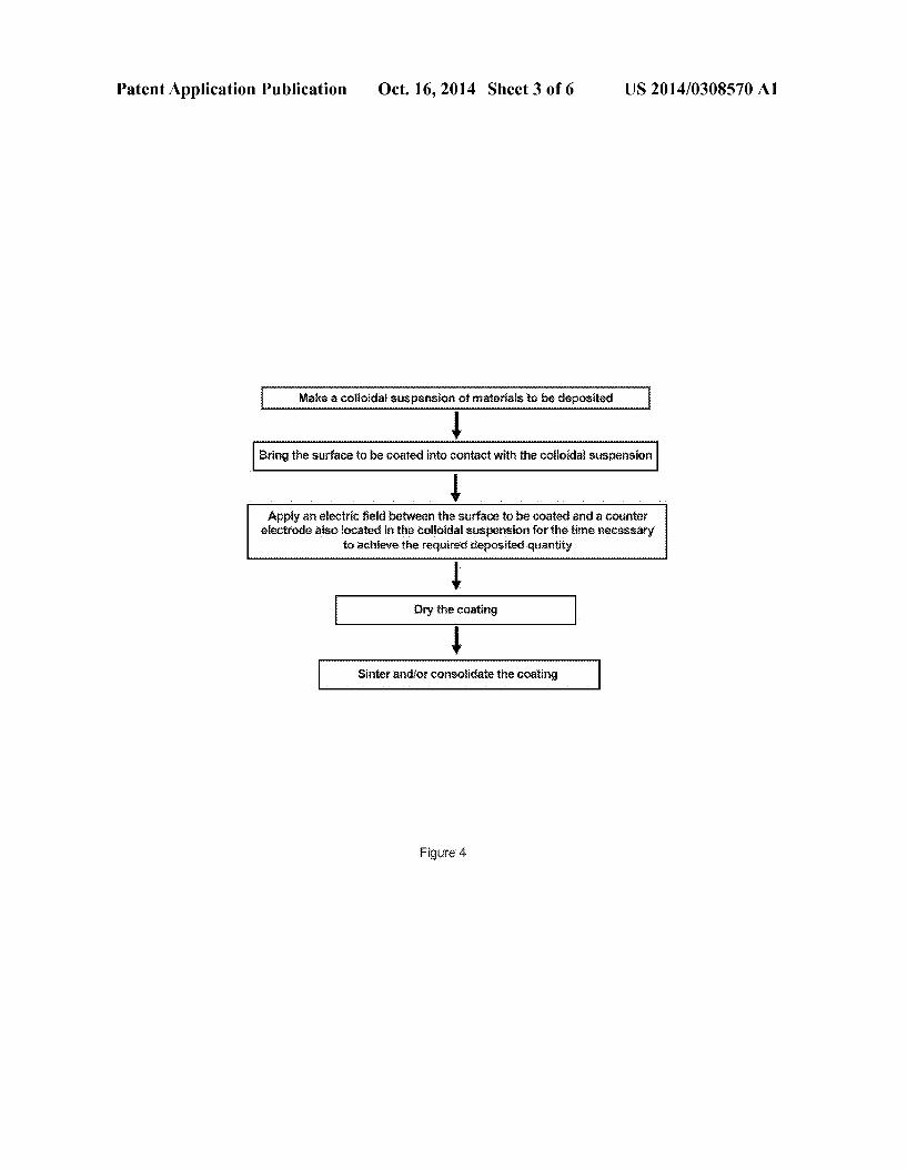
teries. Yet another purpose is to fabricate thin batteries, the thickness of which does not exceed a few tens or even a few hundred micrometers, and that can be integrated onto elec tronic boards, smart cards, RFID labels and other small and/ or flexible devices.
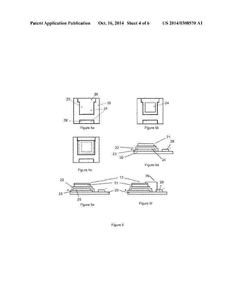
0031. These objectives are achieved using a process for fabrication of all-solid-state thin film batteries, said batteries comprising a film of anode materials (anode film) in electrical contact with an anode collector, a film of solid electrolyte materials (electrolyte film) and a film of cathode materials (cathode film) in electrical contact with a cathode collector, in which process a first electrode film (cathode or anode) is deposited by electrophoresis on a conducting Zone of a Sub strate, said Substrate or its conducting elements can be used as a collector of said battery electrode (anode or cathode); the electrolyte film is deposited by electrophoresis on said first electrode film; a second electrode film (anode or cathode) is deposited on the electrolyte film either by electrophoresis or by another process, such as a vacuum deposition process. 0032 Said process also comprises a so-called consolida tion step of the films deposited by electrophoresis or several so-called consolidation steps made Successively after each deposition of films by electrophoresis. These consolidation steps have the effect of increasing the density of films depos ited by electrophoresis. The consolidation(s) may be done after deposition of the cathode film and/or deposition of the electrolyte film, and/or after deposition of the anode film. It is preferable if it (they) is (are) done after the deposition of the cathode film and/or after the deposition of the electrolyte film, if the anode film is deposited using a technique other than electrophoresis, or after the deposition of the anode film if the anode is film is deposited by electrophoresis. 0033 Said consolidation is possible using a mechanical process, for example by passing between two rollers, by pressing (preferably isostatic) or by shock, or by heat treat ment, or by a combination of these processes. 0034. In one embodiment, the thermal consolidation step and possibly also the mechanical consolidation step is (are) done under a vacuum or under an inert gas. 0035. Thermal consolidation may be preceded or accom panied by one or several mechanical consolidation steps. 0036. In one advantageous embodiment, said consolida tion step is done at a temperature T that preferably does not exceed 0.7 times the melting or decomposition temperature (expressed in C.), and preferably does not exceed 0.5 times (and even more preferably does not exceed 0.3 times) the melting or decomposition temperature (expressed in C.) of:
0037 the material deposited by electrophoresis when it is required to consolidate a single film,

US 2014/0308570 A1
0038 the material with the lowest melting temperature co-deposited by electrophoresis, when it is required to consolidate a film containing particles with different chemical compositions,
0039 materials in the film with the highest melting temperature when several films have to be consolidated simultaneously.
0040. In any case, it is advantageous to not exceed 600°C., and it is preferable to not exceed 500° C. or even 400° C. 0041 More particularly, the process for fabrication of all solid-state thin film batteries according to the invention includes steps to:
0042 (a) Provide a first colloidal suspension “SP+” containing “P+” particles, called a “cathode materials’ Suspension;
0043 (b) Provide a second colloidal suspension “SPn” containing “Pn' particles, called “solid electrolyte mate rials' Suspension;
0044 (c) Provide an insulating substrate completely or partially coated with conducting Surfaces:
0045 (d) Immerse the substrate, possibly locally masked by an insulating stencil, in a bath of said SP+ Suspension containing P+ particles of cathode materials in the presence of a counter electrode, followed by appli cation of an electric Voltage between said Substrate and said counter electrode so as to obtain an electrophoretic deposit containing P+ particles of cathode materials on said substrate to obtain a first BP+ intermediate product;
0046 (e) Immerse said first BP+ intermediate product, that can be locally masked by an insulating stencil, in a bath of said SPn suspension of Pn particles of electrolyte materials in the presence of a counter electrode, fol lowed by application of an electric voltage between said Substrate and said counter electrode so as to obtain an electrophoretic deposit of Pn particles of electrolyte materials on the surface of the cathode film of said BP+ intermediate product, thus obtaining a second BP+Pn intermediate product;
0047 (f) Depositan anode film on the electrolyte film of said second BP+Pn intermediate product, that can be locally masked by a stencil, either by vacuum deposition or by electrophoresis starting from a third “SP-' colloi dal Suspension containing "P-' particles, called an "anode materials' Suspension, to obtain a third BP+PnP-intermediate product.
0048. The next step is to depositan anode current collector film on the anode film of said third BP+PnP- intermediate product to terminate the micro-battery. 0049. When a lithium or metallic lithium alloy anode is deposited as the anode, this anode can also be used as a current collector and can make the connection to a termina tion previously deposited on the Substrate. 0050 Advantageously, said P+ and/or P- and/or Pn par
ticles are nanoparticles. 0051. The substrate may be an insulator with metalized Zones. These metallizations can be used as current collectors or as electrical terminations. 0052. In one embodiment, deposition by electrophoresis is preferably done with a colloidal suspension of particles smaller than 1 um, preferably smaller than 100 nm, or even smaller than 30 nm. The use of nanoparticles, preferably smaller than 100 nm and even more preferably less than 30 nm, can give thin films with an excellent density after con Solidation. This density advantageously reaches 85%, and
Oct. 16, 2014
preferably 90%, and even more preferably 95% of the theo retical density of the solid substance. 0053 Advantageously, the porosity of at least one of the films after consolidation is less than 15%, preferably less than 10% and even more preferably less than 5%. 0054. In the process according to the invention, the aver age size Ds of nanoparticles in the anode, cathode and/or solid electrolyte material is preferably less than 1 um, more preferably less than 100 nm, but it is even more preferable if the nanoparticles are Smaller than 50 nm and even more preferable if they are smaller than 30 nm. This makes it possible to consolidate thin films thermally at a lower tem perature. This is why approximately spherical or cubic shaped particles are preferred. 0055. The average grain size in at least one of the anode, cathode and/or electrolyte films after thermal consolidation is less than 1 um; this increases the life of the battery, probably because the local unbalance of the battery reduces. The heat treatment duration should be appropriate to prevent the risk of excessive (“parasitic') growth of Some grains. 0056. Another purpose of the invention is to obtain highly compact films after the deposition by electrophoresis, free particularly of cavities, cracks and clusters in order to facili tate consolidation at low temperature. 0057. In some embodiments, the Zeta potential of pro cured SP+, SP- and/or SPn colloidal suspensions in steps (a), (b) and (c) is more than 40 mV, or even more than 60 mV, to obtain stable Suspensions not containing any particle clusters that could lead to defects in the deposited films. These sus pensions can contain a steric or preferably electrostatic sta bilizer. 0058. The electrophoretic deposition of nanoparticles can be facilitated by means of a step to deposit a compound designed to reduce the Zeta potential on conducting bands prior to the particle deposition step, before the deposition of the P+, P- and/or Pn particles. 0059 Another purpose of the invention is the deposition of thin films with a very wide variety of chemical compositions that can associate several phases in order to increase functions of the deposits. This purpose is achieved through the use of the electrophoresis technique that makes it easy to deposit films using Suspensions of particle mixes. 0060 Another purpose of the invention is to be able to very precisely control deposited thicknesses (within a thickness range varying from a few hundred nanometers to a few tens or even about a hundred micrometers). More precisely, it is required to have a process that guarantees perfect uniformity of the thickness over the entire surface of the deposit, and excellent reproducibility and repeatability at industrial scale. 0061 Yet another purpose is to achieve optimum economy of the raw material. 0062. These objectives are achieved by use of electro phoresis for preparation of the cathode film, the electrolyte film, and advantageously also the anode film, and by precise control of the deposition current throughout the deposition by electrophoresis. In one advantageous embodiment, the thick ness of the anode and/or cathode film after consolidation is less than 20 m, more preferably less than 10 um and even more preferably less than 5um. 0063 Yet another purpose is to disclose a new easy-to prepare thin film micro-battery on a rigid or flexible substrate, with excellent reliability, long life and low self-discharge, that can be recharged and has very high energy storage den sities. This purpose is achieved by an all-solid-state thin film
US 2014/0308570 A1
micro-battery fabricated by any one of the embodiments and variants of the process described above, comprising a succes sive stack of films consisting of a cathode electrode film deposited on a cathode current collector, an electrolyte film, an anode electrode film that will be directly or indirectly connected to an anode current collector. Preferably, at least one of said cathode electrode, electrolyte and anode electro lyte films, and preferably all three of the films, have a porosity of less than 20%, preferably less than 10% and even more preferably less than 5%.
DESCRIPTION OF THE FIGURES
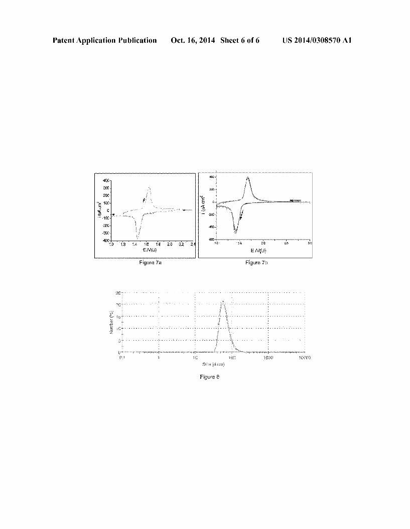
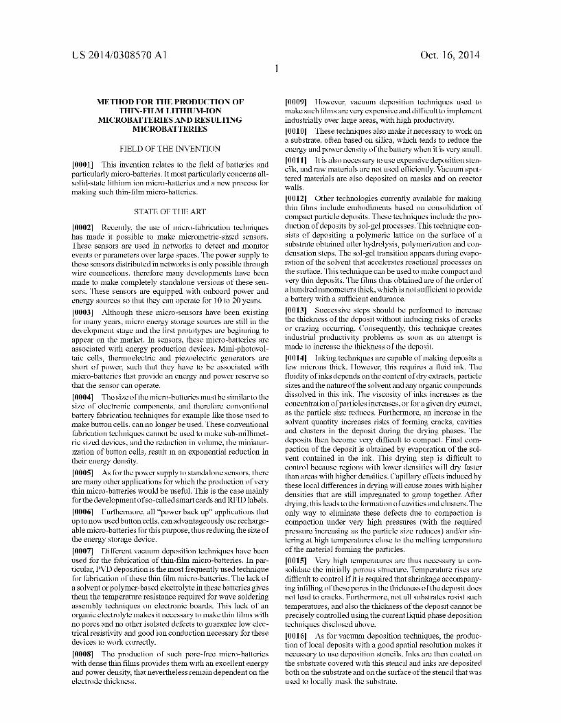
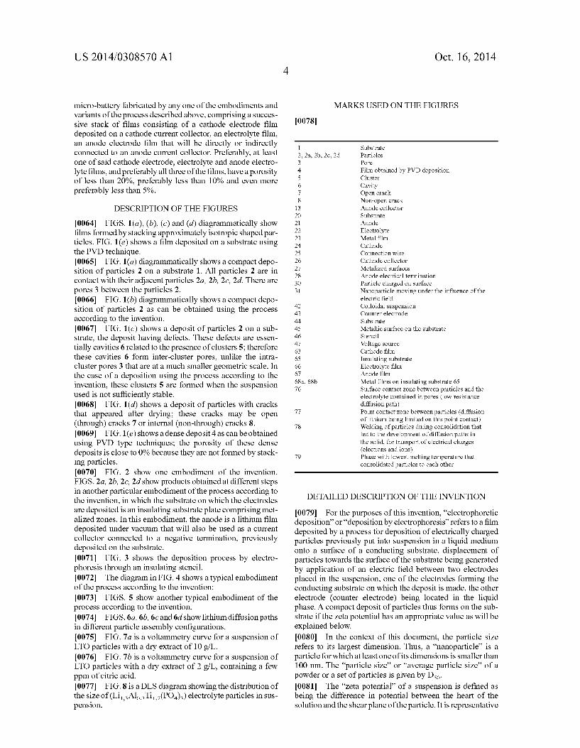
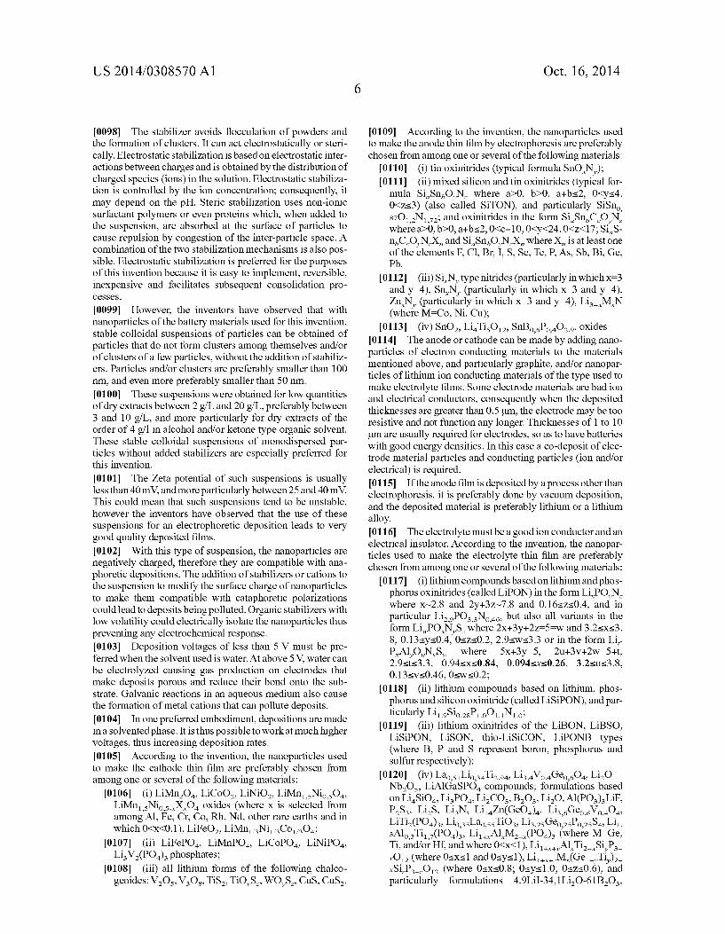
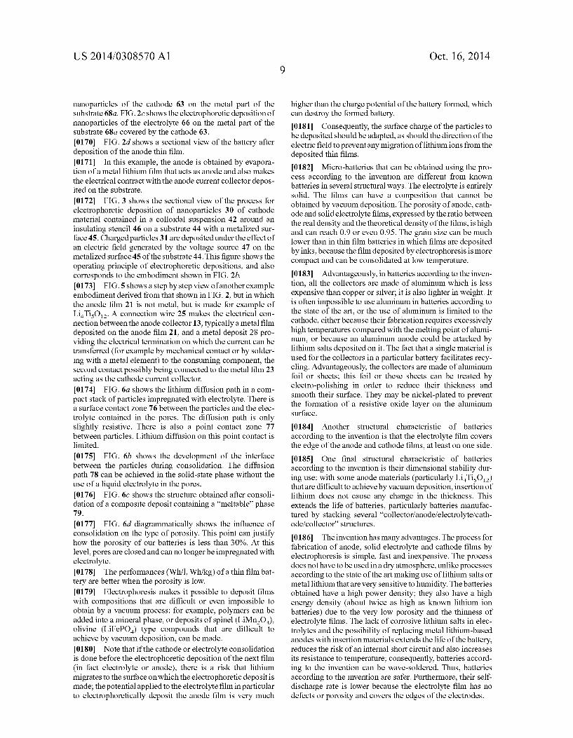
0064 FIGS. 1(a), (b), (c) and (d) diagrammatically show films formed by Stacking approximately isotropic shaped par ticles. FIG. 1(e) shows a film deposited on a substrate using the PVD technique. 0065 FIG. 1(a) diagrammatically shows a compact depo sition of particles 2 on a substrate 1. All particles 2 are in contact with their adjacent particles 2a, 2b, 2c, 2d. There are pores 3 between the particles 2. 0066 FIG. 1(b) diagrammatically shows a compact depo sition of particles 2 as can be obtained using the process according to the invention. 0067 FIG. 1 (c) shows a deposit of particles 2 on a sub strate, the deposit having defects. These defects are essen tially cavities 6 related to the presence of clusters 5; therefore these cavities 6 form inter-cluster pores, unlike the intra cluster pores 3 that are at a much smaller geometric scale. In the case of a deposition using the process according to the invention, these clusters 5 are formed when the suspension used is not sufficiently stable. 0068 FIG. 1 (d) shows a deposit of particles with cracks that appeared after drying; these cracks may be open (through) cracks 7 or internal (non-through) cracks 8. 0069 FIG.1(e) shows a dense deposit 4 as can be obtained using PVD type techniques; the porosity of these dense deposits is close to 0% because they are not formed by stack ing particles. 0070 FIG. 2 show one embodiment of the invention. FIGS. 2a, 2b, 2C, 2d show products obtained at different steps in another particular embodiment of the process according to the invention, in which the substrate on which the electrodes are deposited is an insulating Substrate plate comprising met alized Zones. In this embodiment, the anode is a lithium film deposited under vacuum that will also be used as a current collector connected to a negative termination, previously deposited on the substrate. 0071 FIG. 3 shows the deposition process by electro phoresis through an insulating stencil. 0072 The diagram in FIG. 4 shows a typical embodiment of the process according to the invention: 0073 FIGS. 5 show another typical embodiment of the process according to the invention. 0074 FIGS. 6a, 6b, 6c and 6d show lithium diffusion paths in different particle assembly configurations. 0075 FIG. 7a is a voltammetry curve for a suspension of LTO particles with a dry extract of 10 g/L. 0076 FIG.7b is a voltammetry curve for a suspension of LTO particles with a dry extract of 2 g/L, containing a few ppm of citric acid. 0077 FIG. 8 is a DLS diagram showing the distribution of the size of (LiAlosTi,(PO4)4) electrolyte particles in sus pension.
Oct. 16, 2014
MARKS USED ON THE FIGURES
0078
1 Substrate 2, 2a, 2b, 2c, 2d Particles 3 Pore 4 Film obtained by PVD deposition 5 Cluster 6 Cavity 7 Open crack 8 Non-open crack
13 Anode collector 2O Substrate 21 Anode 22 Electrolyte 23 Metal film 24 Cathode 25 Connection wire 26 Cathode collector 27 Metalized surfaces 28 Anode electrical termination 30 Particle charged on Surface 31 Nanoparticle moving under the influence of the
electric field 42 Colloidal Suspension 43 Counter electrode 44 Substrate 45 Metallic surface on the substrate 46 Stencil 47 Voltage source 63 Cathode film 65 Insulating Substrate 66 Electrolyte film 67 Anode film 68a, 68b Metal films on insulating substrate 65 76 Surface contact zone between particles and the
electrolyte contained in pores (low resistance diffusion path)
77 Point contact Zone between particles (diffusion of lithium being limited on this point contact)
78 Welding of particles during consolidation that led to the development of diffusion paths in the Solid, for transport of electrical charges (electrons and ions)
79 Phase with lowest melting temperature that consolidated particles to each other
DETAILED DESCRIPTION OF THE INVENTION
007.9 For the purposes of this invention, “electrophoretic deposition' or “deposition by electrophoresis” refers to a film deposited by a process for deposition of electrically charged particles previously put into Suspension in a liquid medium onto a Surface of a conducting Substrate, displacement of particles towards the Surface of the Substrate being generated by application of an electric field between two electrodes placed in the Suspension, one of the electrodes forming the conducting Substrate on which the deposit is made, the other electrode (counter electrode) being located in the liquid phase. A compact deposit of particles thus forms on the Sub strate if the Zeta potential has an appropriate value as will be explained below. 0080. In the context of this document, the particle size refers to its largest dimension. Thus, a "nanoparticle' is a particle for which at least one of its dimensions is smaller than 100 nm. The “particle size' or “average particle size' of a powder or a set of particles is given by Dso. I0081. The “Zeta potential of a suspension is defined as being the difference in potential between the heart of the solution and the shear plane of the particle. It is representative

US 2014/0308570 A1
of the stability of a suspension. The shear plane (or hydrody namic radius) corresponds to an imaginary sphere around the particle in which the solvent moves with the particle when the particles move in the solution. The theoretical basis and the determination of the Zeta potential are known to the electro chemist who develops depositions by electrophoresis; it can be deduced from the electrophoretic mobility. There are sev eral marketed techniques and devices for making a direct measurement of the Zeta potential. When the dry extract is Small, the Zeta potential can be measured using a Zetasizer Nano ZS type equipment made by the Malvern Company. This equipment uses optical devices to measure particle dis placement speeds as a function of the electric field applied to them. The solution also has to be highly diluted to enable the passage of light. When the quantity of dry extract is large, the Zeta potential can be measured using acoustophoresis tech niques, for example using a device called "acoustosizer” made by the Colloidal Dynamics Company. The particle speed is then measured by acoustic techniques. 0082 “Dispersant refers to a compound capable of sta bilizing the colloidal suspension and particularly preventing particles from agglomerating. 0083. The term micro-battery used herein refers not to the
total size of the device but rather to its thickness. A lithium ion micro-battery is always micrometric, but it may be much longer and wider depending on the needs of the device that it powers, for example several millimeters or even several cen timeters. 0084. The process according to the invention comprises essential electrophoretic deposition steps of particles of cath ode, anode and solid electrolyte materials. Such a process can significantly reduce the quantity of defects in films obtained in comparison with quantities obtained with known pro cesses, particularly large pores, cavities, crazing and clusters; the quality of deposited films is better when the suspension from which the deposition is made is sufficiently stable. 0085. The process according to the invention can be used
to deposit thin films of electrodes and/or electrolyte. The thickness of these films is usually less than about 20 um, preferably less than about 10 um, and even more preferably less than 5um. I0086. The process for fabrication of all-solid-state thin film batteries according to this invention has an advantageous alternative to known techniques and particularly to PVD deposition techniques, in that it can be used to make very dense depositions at low temperature on large Substrate areas with high deposition rates, easily and very precisely control lable thicknesses (depending on the size of the particles) over a wide thickness range varying from a tenth of a micron to several tens or even hundreds of microns without requiring very expensive investment in complex and not very produc tive machines.
0087 FIGS. 1a to 1c show the differences between intra cluster pores 3 between particles 2 that will be referred to in this document as "pores, and inter-cluster pores 6 between clusters 5 and that will be referred to as "cavities’ 6. 0088 A compact deposit is a deposit without any cavities or cracks. On the other hand, it does have porosity in a ratio expressed as a percentage and calculated as follows:
Porosity (96=(density of the solid-state material-real density) real densityx100
knowing that the “real density' is the density measured on the deposited film and the density of the solid-state material is the
Oct. 16, 2014
Solid density of the deposited material, ignoring the presence of particles that create porosity when stacked. I0089. The following describes each step in the process according to the invention.
Preparation of Suspensions (0090. Deposition is preferably done from very stable SP+, SP-, SPn colloidal suspensions so as to obtain a deposit with a perfectly uniform thickness with no roughness, few defects and as compact as possible after the electrophoretic deposi tion process. The stability of Suspensions depends on the size of the P+, P-, Pn, particles and the nature of the solvent used and the stabilizer that was used to stabilize the colloidal Suspension. Procurement of these colloidal Suspensions cor responds to steps (a), (b) and (c) in a main embodiment of the process according to the invention. (0091 “SP+” refers to a colloidal suspension of “P+” par ticles of materials used to obtain a cathode film, “SP-” refers to a colloidal suspension containing P-particles of materials used to obtain an anode film, “SPn' refers to a colloidal suspension of “Pn' particles of materials used to obtain an electrolyte film. 0092 Colloidal suspensions containing nanometric sized particles are preferred to facilitate Subsequent consolidation of the deposit if necessary and to assure that thin film deposits can be made with very precise thicknesses and profiles (roughness). The average size Dso of these particles is pref erably less than 100 nm, and more preferably (especially in the case in which the suspension comprises particles of mate rials with high melting points) less than 30 nm. Consolidation of a deposit with small particles is very much facilitated if the deposit is compact. Particles with a parallelepiped shape may also be used. 0093 Making electrophoretic depositions from stable col loidal Suspensions avoids the formation of pores, cavities and clusters that are prejudicial to consolidation of the deposit. Furthermore with this technique, it is possible to have depos its with excellent compactness without necessarily making use of mechanical pressing and unbinding, regardless of the size of the deposited particles. 0094. This high compaction of the deposit is obtained although the Suspensions are highly diluted, with low con tents of dry extracts. 0.095 The stability of suspensions can be expressed by their Zeta potential. In the context of this invention, the sus pension is considered to be stable when its Zeta potential is more than 40 mV, and very stable when it is more than 60 mV. On the other hand, particle clusters can develop when the Zeta potential is less than 20 mV. Thus, depositions are preferably done from colloidal Suspensions with a Zeta potential of more than 40 mV, and even more preferably 60 mV (absolute value) to guarantee good compaction of the thin film. 0096 Colloidal suspensions that will be used in electro phoresis comprise an electric insulating solvent that may be an organic solvent, or demineralized water, or a mix of Sol vents, and particles to be deposited; colloidal Suspensions may also comprise one or several stabilizers. 0097. In a stable suspension, the particles do not agglom erate with each other to create clusters that could induce cavities, clusters and/or important defects in the deposit. Par ticles remain isolated in the Suspension. Also in one embodi ment of this invention, the stability of the Suspension neces sary to obtain a compact deposit is obtained through the addition of stabilizers.
US 2014/0308570 A1
0098. The stabilizer avoids flocculation of powders and the formation of clusters. It can act electrostatically or steri cally. Electrostatic stabilization is based on electrostatic inter actions between charges and is obtained by the distribution of charged species (ions) in the solution. Electrostatic stabiliza tion is controlled by the ion concentration; consequently, it may depend on the pH. Steric stabilization uses non-ionic Surfactant polymers or even proteins which, when added to the Suspension, are absorbed at the Surface of particles to cause repulsion by congestion of the inter-particle space. A combination of the two stabilization mechanisms is also pos sible. Electrostatic stabilization is preferred for the purposes of this invention because it is easy to implement, reversible, inexpensive and facilitates Subsequent consolidation pro CCSSCS.
0099. However, the inventors have observed that with nanoparticles of the battery materials used for this invention, stable colloidal suspensions of particles can be obtained of particles that do not form clusters among themselves and/or of clusters of a few particles, without the addition of stabiliz ers. Particles and/or clusters are preferably smaller than 100 nm, and even more preferably smaller than 50 nm. 0100. These suspensions were obtained for low quantities of dry extracts between 2 g/L and 20 g/L, preferably between 3 and 10 g/L, and more particularly for dry extracts of the order of 4 g/l in alcohol and/or ketone type organic solvent. These stable colloidal Suspensions of monodispersed par ticles without added stabilizers are especially preferred for this invention. 0101 The Zeta potential of such suspensions is usually less than 40 mV, and more particularly between 25 and 40 mV. This could mean that Such Suspensions tend to be unstable, however the inventors have observed that the use of these Suspensions for an electrophoretic deposition leads to very good quality deposited films. 0102. With this type of suspension, the nanoparticles are negatively charged, therefore they are compatible with ana phoretic depositions. The addition of stabilizers or cations to the Suspension to modify the Surface charge of nanoparticles to make them compatible with cataphoretic polarizations could lead to deposits being polluted. Organic stabilizers with low volatility could electrically isolate the nanoparticles thus preventing any electrochemical response. 0103) Deposition voltages of less than 5 V must be pre ferred when the solvent used is water. At above 5V, water can be electrolyzed causing gas production on electrodes that make deposits porous and reduce their bond onto the Sub strate. Galvanic reactions in an aqueous medium also cause the formation of metal cations that can pollute deposits. 0104. In one preferred embodiment, depositions are made in a solvented phase. It is thus possible to work at much higher Voltages, thus increasing deposition rates. 0105. According to the invention, the nanoparticles used
to make the cathode thin film are preferably chosen from among one or several of the following materials:
I0106 (i) LiMnO, LiCoO, LiNiO, LiMnsNio O, LiMns Nios-X,O oxides (where X is selected from among Al, Fe, Cr, Co., Rh, Nd, other rare earths and in which 0<x<0.1), LiFeC), LiMn/Ni Co-O;
0107 (ii) LiFePO, LiMnPO, LiCoPO, LiNiPO, LiV(PO) phosphates:
0.108 (iii) all lithium forms of the following chalco genides: V.O.s, VOs, TiS, TiOS, WOS, CuS, CuS.
Oct. 16, 2014
0109 According to the invention, the nanoparticles used to make the anode thin film by electrophoresis are preferably chosen from among one or several of the following materials:
10110 (i) tin oxinitrides (typical formula SnO.N.); 0.111 (ii) mixed silicon and tin oximitrides (typical for mula Si,SnO, N, where a>0, b>0, a+bs2, 0<ys4. 0<zs3) (also called SiTON), and particularly SiSno, 87O,N72; and oxinitrides in the form Si,SnC.O.N. wheread>0, b>0, a+bs2,0<c-10,0<y<24.0<z<17: Si,S- nCONX, and Si,SnO,NX, where X, is at least one of the elements F, Cl, Br, I, S, Se, Te, P. As, Sb, Bi, Ge. Pb.
I0112 (iii) SiN, type nitrides (particularly in which x=3 and y=4), Sn, N, (particularly in which x=3 and y=4), Zn, N, (particularly in which x=3 and y=4), Li, MN (where M=Co, Ni, Cu);
I0113 (iv) SnO2, Li Tis02, SnBoPoOo. oxides 0114. The anode or cathode can be made by adding nano particles of electron conducting materials to the materials mentioned above, and particularly graphite, and/or nanopar ticles of lithium ion conducting materials of the type used to make electrolyte films. Some electrode materials are bad ion and electrical conductors, consequently when the deposited thicknesses are greater than 0.5um, the electrode may be too resistive and not function any longer. Thicknesses of 1 to 10 um are usually required for electrodes, so as to have batteries with good energy densities. In this case a co-deposit of elec trode material particles and conducting particles (ion and/or electrical) is required. 0115 If the anode film is deposited by a process other than electrophoresis, it is preferably done by vacuum deposition, and the deposited material is preferably lithium or a lithium alloy. 0116. The electrolyte must be a good ion conductor and an electrical insulator. According to the invention, the nanopar ticles used to make the electrolyte thin film are preferably chosen from among one or several of the following materials:
0.117 (i) lithium compounds based onlithium and phos phorus oxinitrides (called LiPON) in the form Li, PO.N. where X-2.8 and 2y+3Z-7.8 and 0.16s.750.4, and in particular LioPONoas, but also all variants in the form LiPO.N.S. where 2x+3y+2z 5–w and 3.2sxs3. 8, 0.13sys0.4, Oszs0.2, 2.9sws3.3 or in the form Li P,Al,ONS, where 5x+3y=5, 2u-3v+2w=5+t, 2.9sts3.3, 0.94sXs0.84, 0.094sys0.26, 3.2sus3.8, 0.13svs0.46, 0<ws0.2:
0118 (ii) lithium compounds based on lithium, phos phorus and siliconoximitride (called LiSiPON), and par ticularly LioSio.2sPoC). No:
0119 (iii) lithium oximitrides of the LiBON, LiBSO, LiSiPON, LiSON, thio-LiSiCON, LiPONB types (where B, P and S represent boron, phosphorus and sulfur respectively):
I0120 (iv) Laos, LiosTi294, LisaVoGeog04, Li2O NbOs, LiAlGaSPO compounds; formulations based on Li SiO, LiPO, LiCO, BOs, Li2O, Al(POs). LiF. PSs, Li2S, LiN, Lila Zn(GeO4)4. Lis. Ceos Vol.O. LiTi2(PO4)3. LiossLaoss TiO3. LissGeo2sPo2s.S4. Li, 3.Alo,Ti,(PO), Li, Al, M.(PO) (where M-Ge. Ti, and/or Hf, and where 0<x<1), LiAl,Ti, Si, P. O2 (where 0<x<1 and 0sys1), Li-M, (Gel-Ti.)
a SiPO (where 0<xs0.8; 0sys1.0; 0szs0.6), and particularly formulations 4.9LiI-34.1LiO-61BO,

US 2014/0308570 A1
0.30LiS-0.26BS-0.44LiI, 60LiS-40SiS, 0.02LisPO-0.98(LiS SiS), 2(Li TiSioPO,2)- AlPO, 0.7LiS-0.3PSs.
0121 Once the required chemical composition (i.e. the nature of the powder or powder mixes) has been defined, the nanoparticles are put into solution in an appropriate liquid phase. A stabilizer is added in Some embodiments, in order to obtain a suspension for which the Zeta potential is preferably greater than 40 mV, and even more preferably more than 60 mV. 0122. However, advantageously, the Suspensions used do not contain any stabilizers, and particularly have low contents of dry extracts (usually less than 10 g/L), and especially they contain particles smaller than 100 nm and preferably smaller than 50 nm. In this case, the Zeta potential of the suspension is usually between 25 and 40 mV. 0123 For example, the solvents used can be based on ketone, alcohol or a mix of the two. 0.124 Steric stabilizers that could be used include particu larly polyethylene imine (PEI), polyacrylic acid (PAA), citric acid and nitrocellulose provided that they are soluble in the chosen organic solvent. 0.125 Electrostatic stabilizations may be made by adding iodide, by adding acids or bases. The solution may be acidi fied or basified by the addition of traces of water and acids when the Suspension is made in a solvented phase. 0126 The electrical conductivity of the suspension may be controlled to obtain a large potential gradient between the two electrodes without any risk of dielectric breakdown. Pref erably, the conductivity of the colloidal suspension is between 1 and 20 LS/cm. Small quantities of strong acids and bases can be added to control the conductivity of the suspen sion and charge particle Surfaces. 0127. It may be necessary to perform a powder grinding and/or dispersion step before the nanoparticles are put into Suspension, to de-agglomerate the particles and possibly adjust their size (to obtain an average size smaller than 100 nm or even less than 30 nm) and reduce the size dispersion, so as to obtain a stable Suspension with cluster-free nanometric sized particles. Ultrasounds may also be used to assist in deagglomeration and putting particles into Suspension. 0128 Defects created in particles during the grinding and dispersion steps can also reduce the consolidation tempera ture, in the same way as when mechanical compressions are performed.
Electrophoretic Deposition of Films
0129. According to the invention, at least the cathode film and the electrolyte film are deposited electrophoretically. The electrophoretic deposition of particles is made by application of an electric field between the substrate on which the deposit is made and the counter electrode, in order to move the charged particles in the colloidal suspension and to deposit them on the substrate. The lack of binders and other solvents deposited on the surface with the particles can result in very compact deposits. The compactness obtained due to electro phoretic deposition and the lack of any large quantities of organic compounds in the deposit can limit or even prevent risks of crazing or the appearance of other defects in the deposit during drying steps. 0130. Furthermore, due to the fact that the deposit obtained by electrophoresis does not contain any binders or other organic compounds, the process according to this inven tion does not require any burning or evaporation steps of
Oct. 16, 2014
corrosive or noxious compounds. The increase in economic and environmental constraints makes it necessary to reduce releases into the atmosphere and this invention thus satisfies these constraints. I0131 Furthermore, burning of these organic compounds tends to create empty Zones, cavities in the deposit that will subsequently be difficult to fill. These unbinding steps can also lead to pollution of the surfaces of deposited particles. 0.132. Furthermore, the deposition rate can be very high depending on the applied electric field and the electrophoretic mobility of particles in Suspension. For an applied Voltage of 200 V, deposition rates of the order of 10 um/min can be obtained. 0.133 FIG. 3 shows the operating principle of deposition by electrophoresis. I0134. The inventor has observed that this technique can be used to make deposits on very large areas with excellent uniformity and very high precision (provided that particle concentrations and electric fields are uniform over the surface of the substrate). This technique can also be used to cover three-dimensional Surfaces. 0.135 The thickness of each cathode, anode and solid elec trolyte film is preferably between 1 um and 10 um. 0.136. A mechanical consolidation step (for example by pressing) can be carried out after deposition of the film and before the heat treatment sintering step if there is one, in order to further compact particles and induce particle deformations that will further simplify subsequent consolidation. 0.137 Deposition by electrophoresis may be applied in a "batch” (static) type process or in a continuous process. 0.138. During the electrophoretic deposition, a stabilized power Supply can be used to apply a Voltage between the conducting Substrate and a counter electrode located in the colloidal Suspension. 0.139. This voltage may be direct or alternating. Precise monitoring of the currents obtained helps to monitor the deposited thicknesses and to control them precisely. When the deposited films are insulating, their thickness affects the value of the electric field and in this case, a controlled current deposition mode is preferred. The value of the electric field is modified depending on the resistivity of the interface. 0140. This deposition technique also enables perfect cov erage of the Surface regardless of its geometry and the pres ence of roughness defects. Consequently, it can guarantee dielectric properties of the electrolyte film. 0141 When materials that do not conduct electricity or conduct electricity only slightly are deposited on the Surface of a Substrate, any Zones that are not so well coated conduct better and thus locally concentrate a higher deposition rate that tends to compensate or even eliminate the defect. The intrinsic quality of the deposits obtained is thus excellent, there are very few defects and the deposits are very homoge
OUS.
0142. The diagram in FIG. 4 shows a typical embodiment of the process according to the invention, in this case shown for each of the films: 0.143 Step 1: Preparation of suspensions. The powders used have the chemical composition of the coating (thin film) that is to be deposited. 0144 Step 2: Immersion of the substrate in the colloidal Suspension. The colloidal Suspension can cover the entire Surface of the Substrate. In one particular embodiment, a stencil can be applied to the surface of the substrate so as to

US 2014/0308570 A1
limit the area in contact with the Suspension, consequently reducing the area of the deposit. 0145 Step 3: Application of an electric field between the substrate and a counter electrode located in the colloidal suspension. This electric field can be constant and/or variable (alternating). The average direction of the electric field, in other words the potential applied to the electrodes, is adapted to the charge of the particle to be deposited (cataphoresis or anaphoresis). 0146 Step 4: Drying. Drying conditions depend on the deposited thickness and the nature of the solvent. 0147 A mechanical consolidation step can be made on the wet film before drying, for example by calendering or static compression; this can improve the quality of the film, but does not replace dry consolidation. 0148 Step 5: Consolidation. Consolidation is done by mechanical consolidation and/or heat treatment. 0149 Consolidation may also be done after deposition of each new film on several films at the same time. 0150 FIG. 5 shows another embodiment of the process according to the invention.
Consolidation of the Deposit 0151. Advantageously, deposited films are consolidated to reduce the porosity of the coating. This consolidation step of the deposit can be done:
0152 by a mechanical means, particularly by isostatic pressing. The applied pressure in Some embodiments is more than 250 MPa or even more than 400 MPa. How ever, advantageously, the applied pressure is between 30 and 100 MPa, and preferably between 40 and 60 MPa.
0153 by heat treatment. The temperature depends closely on the chemical composition of the deposited powders. Depending on the nature of the deposited materials, it may also be useful to maintain a controlled atmosphere to prevent oxidation of the coating:
0154 by a combination of thermal and mechanical means, and particularly by high pressure sintering;
0155 The substrate is composed of an insulating material with metalized and generally conducting Zones. It is preferred to avoid heating it to high temperatures during fabrication of the battery, to prevent any risk of oxidation and deterioration of Surface properties. The reduction in Surface oxidation is particularly beneficial to reduce electrical contact resistances, which is an essential point in operation of energy storage and/or production devices. 0156 Very high quality electrophoretic films like those described above and particularly compact films, can reduce the heat treatment duration and temperature and limit shrink age related to these treatments, to obtain a homogeneous nanocrystalline structure. This contributes to obtaining dense films with no defects. O157. The inventor has observed that the heat treatment temperature can be reduced if the size of deposited particles is reduced. Thus, thin or relatively thick film deposits can be made with porosity of less than 10%, preferably less than 5% or even 2%, without needing to apply high temperatures and/or long heat treatment times. Furthermore, this compac tion technology for low temperature deposits considerably reduces risks of shrinkage. Thus, it is no longer necessary to use highly complex and expensive heat treatment cycles to consolidate battery electrode and electrolyte deposits. 0158. During the mechanical and/or thermal consolida tion phase, it can be advantageous to work under a vacuum or
Oct. 16, 2014
under an inert atmosphere to prevent the appearance of pol lution on particle surfaces that could be harmful to the con Solidation mechanism of particles among each other. 0159 For particle sizes like those used in the process according to the invention, the increase in Surface energies becomes the main driving force of consolidation by heat treatment; this results in a large reduction in consolidation temperatures when the particle size reduces. However, if this reduction in consolidation temperatures is to be effective, it is necessary for particles to be firstly mechanically compacted and/or deposited with compact stacking The multiplication of mechanical contacts between these particles facilitates diffu sion processes that cause consolidation. Thus, pressing is usually applied to compact deposits. 0160 The presence of clusters and inter-cluster cavities also has an influence on consolidation. As cavity sizes increase, the diffusion distance also increases and the con Solidation temperature necessary to obtain good consolida tion increases. 0.161 Thus, with nanoparticles deposited by electrophore sis, it is possible to approach the theoretical geometric density of a compact stack of spheres (74%), without a mechanical compaction step. 0162 Such a result is not possible usinginking techniques. Deposition of nanoparticles using the ink technique men tioned above is very difficult with thin films because the reduction in particle size increases the viscosity of Suspen sions. Thus, the dry extract has to be reduced by increasing the proportion of solvent; in this case, pores and cavities are induced when much of the solvent is eliminated from the raw films, and it is practically impossible to fill them without the use of extreme temperatures and/or pressures. 0163 The high compactness of the deposit obtained by electrophoresis and the Small quantity of solvent to be evapo rated very significantly reduce the risk of appearance of cracks after drying. Furthermore, the Small size of particles and their large specific area tend to facilitate consolidation steps by heat treatment (often called “sintering in this con text). The deposit can thus be consolidated at temperatures equal to approximately 0.7T, or even 0.5T, or 0.3T, where (0164. T, is the melting temperature (expressed in C.) of the solid material with chemical composition identical to that of the deposited particle. The “melting temperature' term in this case refers to the decomposition temperature for the case of Substances for which there is no melting point. 0.165. When the film is composed of a mix of materials, the heat treatment temperature is chosen relative to the melting temperature of the material with the lowest melting tempera ture.
0166 Mechanical compression can also be applied to this deposit in order to further reduce this consolidation tempera ture, in order to further increase its compactness and/or create isolated defects that will contribute to accelerating the con Solidation process and obtaining thin films with no pores. 0.167 Such a process for the fabrication of thin films can be used directly on Substrates such as metalized polymers, aluminum foil with low melting temperatures. 0.168. However, since nanoparticles are very sensitive to surface pollution, it is preferable to perform these consolida tion treatments under a vacuum or under an inert atmosphere. 0169 FIG. 2a shows procurement of a substrate, in this case in the form of an insulating plate 65 coated partially with metal films 68a, 68b corresponding to a main embodiment of the invention. FIG. 2b shows electrophoretic deposition of
US 2014/0308570 A1
nanoparticles of the cathode 63 on the metal part of the substrate 68a. FIG.2c shows the electrophoretic deposition of nanoparticles of the electrolyte 66 on the metal part of the substrate 68a covered by the cathode 63. (0170 FIG. 2d shows a sectional view of the battery after deposition of the anode thin film. 0171 In this example, the anode is obtained by evapora tion of a metal lithium film that acts as anode and also makes the electrical contract with the anode current collector depos ited on the substrate.
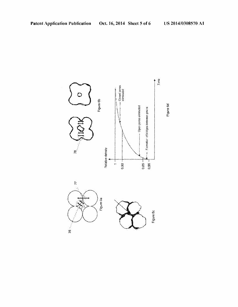
0172 FIG. 3 shows the sectional view of the process for electrophoretic deposition of nanoparticles 30 of cathode material contained in a colloidal Suspension 42 around an insulating stencil 46 on a Substrate 44 with a metalized Sur face 45. Charged particles 31 are deposited under the effect of an electric field generated by the voltage source 47 on the metalized surface 45 of the substrate 44. This figure shows the operating principle of electrophoretic depositions, and also corresponds to the embodiment shown in FIG.2b. 0173 FIG.5 shows a step by step view of another example embodiment derived from that shown in FIG. 2, but in which the anode film 21 is not metal, but is made for example of Li TiO2. A connection wire 25 makes the electrical con nection between the anode collector 13, typically a metal film deposited on the anode film 21, and a metal deposit 28 pro viding the electrical termination on which the current can be transferred (for example by mechanical contact or by solder ing with a metal element) to the consuming component, the second contact possibly being connected to the metal film 23 acting as the cathode current collector. 0.174 FIG. 6a shows the lithium diffusion path in a com pact stack of particles impregnated with electrolyte. There is a surface contact Zone 76 between the particles and the elec trolyte contained in the pores. The diffusion path is only slightly resistive. There is also a point contact Zone 77 between particles. Lithium diffusion on this point contact is limited.
(0175 FIG. 6b shows the development of the interface between the particles during consolidation. The diffusion path 78 can be achieved in the solid-state phase without the use of a liquid electrolyte in the pores. 0176 FIG. 6c shows the structure obtained after consoli dation of a composite deposit containing a "meltable phase 79.
0177 FIG. 6d diagrammatically shows the influence of consolidation on the type of porosity. This point can justify how the porosity of our batteries is less than 30%. At this level, pores are closed and can no longer be impregnated with electrolyte. (0178. The performances (Wh/l. Wh/kg) of a thin film bat tery are better when the porosity is low. 0179 Electrophoresis makes it possible to deposit films with compositions that are difficult or even impossible to obtain by a vacuum process; for example, polymers can be added into a mineral phase, or deposits of spinel (LiMn2O4), olivine (LiFePO) type compounds that are difficult to achieve by vacuum deposition, can be made. 0180. Note that if the cathode or electrolyte consolidation
is done before the electrophoretic deposition of the next film (in fact electrolyte or anode), there is a risk that lithium migrates to the Surface on which the electrophoretic deposit is made; the potential applied to the electrolyte film in particular to electrophoretically deposit the anode film is very much
Oct. 16, 2014
higher than the charge potential of the battery formed, which can destroy the formed battery. 0181 Consequently, the surface charge of the particles to be deposited should be adapted, as should the direction of the electric field to prevent any migration of lithium ions from the deposited thin films. 0182 Micro-batteries that can be obtained using the pro cess according to the invention are different from known batteries in several structural ways. The electrolyte is entirely Solid. The films can have a composition that cannot be obtained by vacuum deposition. The porosity of anode, cath ode and solid electrolyte films, expressed by the ratio between the real density and the theoretical density of the films, is high and can reach 0.9 or even 0.95. The grain size can be much lower than in thin film batteries in which films are deposited by inks, because the film deposited by electrophoresis is more compact and can be consolidated at low temperature. 0183 Advantageously, in batteries according to the inven tion, all the collectors are made of aluminum which is less expensive than copper or silver, it is also lighter in weight. It is often impossible to use aluminum in batteries according to the state of the art, or the use of aluminum is limited to the cathode, either because their fabrication requires excessively high temperatures compared with the melting point of alumi num, or because an aluminum anode could be attacked by lithium salts deposited on it. The fact that a single material is used for the collectors in a particular battery facilitates recy cling. Advantageously, the collectors are made of aluminum foil or sheets; this foil or these sheets can be treated by electro-polishing in order to reduce their thickness and smooth their surface. They may be nickel-plated to prevent the formation of a resistive oxide layer on the aluminum Surface.
0.184 Another structural characteristic of batteries according to the invention is that the electrolyte film covers the edge of the anode and cathode films, at least on one side. 0185. One final structural characteristic of batteries according to the invention is their dimensional stability dur ing use: with Some anode materials (particularly Li TisC) that are difficult to achieve by vacuum deposition, insertion of lithium does not cause any change in the thickness. This extends the life of batteries, particularly batteries manufac tured by stacking several “collector/anode/electrolyte/cath ode? collector” structures.
0186 The invention has many advantages. The process for fabrication of anode, solid electrolyte and cathode films by electrophoresis is simple, fast and inexpensive. The process does not have to be used in a dry atmosphere, unlike processes according to the state of the art making use of lithium salts or metal lithium that are very sensitive to humidity. The batteries obtained have a high power density; they also have a high energy density (about twice as high as known lithium ion batteries) due to the very low porosity and the thinness of electrolyte films. The lack of corrosive lithium salts in elec trolytes and the possibility of replacing metal lithium-based anodes with insertion materials extends the life of the battery, reduces the risk of an internal short circuit and also increases its resistance to temperature; consequently, batteries accord ing to the invention can be wave-soldered. Thus, batteries according to the invention are safer. Furthermore, their self discharge rate is lower because the electrolyte film has no defects or porosity and covers the edges of the electrodes.
US 2014/0308570 A1
0187. The process according to the invention can be implemented as follows. The following examples are given for illustration and do not limit the scope of the invention.
EXAMPLE1
Fabrication of a Battery
1—Preparation of the SP+ Colloidal Suspension 0188 A LiMnO, powder composed of clusters of nano particles is synthesized to obtain the SP+ suspension of P+ particles for the cathode material. This is done using Pechi ni’s process described in the article “Synthesis and Electro chemical Studies of Spinel Phase LiMnO, Cathode Materi als Prepared by the Pechini Process', W. Liu, G. C. Farrington, F. Chaput, B. Dunn, J. Electrochem. Soc., vol. 143, No. 3, 1996. After the calcination step at 600° C., the powder contains clusters with a size of between 50 nm and 100 nm. 0189 This powder is then put into suspension in ethanol with a dry extract of LiMnO, equal to 20 g/l. 0190. The SP+ suspension is poured into the bowl of a ball grinder previously filled with 0.1 mm diameter ceramic balls. Grinding takes place for 2 hours in the presence of a few hundred ppm of a complexing agent, for example polyacrylic acid, to obtain a colloidal solution with particles (Ds) with a size equal to 10 nm. The Zeta potential of the Suspension is equal to about 65 mV.
2—Deposition of the Cathode Film (0191). The LiMnO, particles contained in the suspension are then deposited on the metalized area of the substrate (see FIG. 2b). The deposition is made locally using an insulating stencil (see FIGS. 2b and 3). The deposition is made by applying a voltage of 100 V between the metalized area of the Substrate on which the deposit is made and a counter elec trode, both immersed in the colloidal Suspension, until a 5um thick deposit is obtained. The deposit is then dried for 1 hour at 90° C. 0.192 The deposit is then compacted by a compression and then annealed at 500° C. for 900 seconds.
3—Preparation of the SPn Colloidal Suspension 0193 The first step in making the colloidal suspension containing electrolyte particles is to synthesize nanometric powders of Lis AlosTi,(PO4), using the process described in the “Thin-film lithium-ion battery derived from Li, Al. 3 Ti(PO4) sintered pellets' publication by Xiao et al., pub lished in Trans. Nonferrous Me. Soc. China 16 (2006), p. 281-285. Stoechiometric quantities of Li (CH COO).2H2O and Al(NO).9HO are dissolved in CHOCH2CH2OH. and PO(OCH) is then added to this mixture while stirring. After adding the Stoechiometric quantity of demineralized water for hydrolysis of alkoxides, the suspension obtained is dried at 140°C. for 4 hours to form an Lisalo,Ti,(PO). gel. This gel is then calcinated at 900° C. for 2 hours to obtain an agglomerated powder of Li. Alo-Ti,(PO); this pow der is then put into Suspension in ethanol at a concentration equal to 20 g/l. 0194 The suspension is added into the bowl of a ball grinder previously filled with 0.1 mm diameter ceramic balls. Grinding for 3 hours in the presence of a small quantity of polyacrylic acid that acts as a complexing agent results in a
Oct. 16, 2014
colloidal Solution with particles with size Dso equal to 15 nm. The Zeta potential of the suspension is of the order of 60 mV.
4 Deposition of the Electrolyte Film
(0195) The LiAlo,Ti,(PO), particles obtained in the Suspension are Subsequently deposited on the consolidated deposit of LiMnO, by applying a voltage of 100 V between the substrate and a counter electrode both immersed in the colloidal Suspension, until a 1.5um thick deposit is obtained. (0196) The cathode (LiMnO) is coated with a thin film of electrolyte nanoparticles. The electrolyte film is dried at 90° C. 0197) The deposit is then compacted by compression and then annealed at 350° C. for 900 seconds.
5—Deposition of the Anode Film 0198 The substrate with the cathode and electrolyte deposits is then placed in a vacuum chamber, and the lithium anode is deposited locally on a surface covering the Surface facing the cathode and the electrical termination deposited on the substrate, on the electrolyte. 0199 When a metal lithium anode is used, an encapsula tion film must be deposited to protect the battery cell from external aggression.
EXAMPLE 2
Fabrication of an Anode Film
1—Preparation of the Substrate 0200. A 15um thick aluminum foil is procured. The foil is then placed in an unwinder and is placed on a Support frame, So as to create a rigid support structure for the aluminum foil without creasing the foil. This Support frame is designed with an insulating external Surface with the presence of electrical contacts on the internal Surfaces. These internal conducting Surfaces are in contact with the aluminum foil and impose a potential on it. The aluminum foil in its frame is then immersed in a Surface cleaning bath. This cleaning is done by immersion in a bath of detergent made by NGL technologie under ultrasounds followed by rinsing with distilled water. 0201 Once the surface was cleaned, we performed an electro-polishing treatment in a solution with chemical com position equal to 80% absolute ethanol, 13.8% distilled water and 6.2% perchloric acid at 70%. The aluminum was electro polished at a polarization under 15V with a lead counter electrode. The treatment bath was cooled to prevent overheat ing due to high current densities. Other bath formulations may be used for a better surface quality, for example baths based on EPS 1250 or EPS 1300 type solutions supplied by EP-Systems. 0202 After the electro-polishing treatment, the surface was rinsed with distilled water.
2 Preparation of an SP- Colloidal Suspension 0203 This colloidal suspension was made without the addition of stabilizers, to guarantee an excellent purity of the electrode. We did this by preparing a colloidal suspension of Li TiO2 in alcohol by grinding and dispersing Li TisC) nanoparticles. 0204 Li TiO2 nanoparticles were purchased from Ald rich, and then ground in ethyl alcohol at a concentration of 10 g/l. After this grinding-dispersion step, the Suspension was
US 2014/0308570 A1
ultrasonically irradiated and then allowed to settle. We drew off only the float of the suspension after settlement in order to be sure of obtaining a colloidal suspension of nanoparticles with no clusters larger than 100 nm. 0205. A suspension was thus obtained containing no sta
bilizer. We observed that the stability of nanocolloids depended largely on the particle size and their concentration in the suspension. When the particle size is close to about ten nanometers, particles can be stable in Suspensions without any added stabilizers. The high specific area of these particles and their low mass are such that interactions result in making the system behave like a real gas that can condense resulting in a colloidal crystal. Electrophoretic depositions of these nanoparticles result in condensation of this so-called colloi dal crystal phase on the surface of the substrate.
3—Deposition of the Anode Film 0206. A thin film of Li TisC) particles was deposited by electrophoresis on the electro-polished aluminum foil obtained in step 1 above. 0207. The deposition conditions used were 10V/cm, which gave a compact deposi about 0.5 um thick after only thirty seconds of anaphoresis. 0208. The deposit was then annealed at 500° C. for 1 hour and then pressed at 50 MPa. 0209. The result obtained was an anode. 0210. A cyclic voltammetry curve was then plotted on this electrode at 0.1 V/sec in order to validate its insertion prop erties with regard to lithium ions. FIG. 23a shows an illustra tion of the curve thus obtained.
EXAMPLE 3
Fabrication of an Anode Film
0211 2. 0212. The preparation process for the suspension of SP particles is similar to that used in example 2, except that the Suspension of Li TiO2 particles was diluted to 2 g/l and that citric acid was added to the Suspension at a concentration of 1x10⁻³ M. The suspension was ultrasonically irradiated and the float was retrieved after settlement. 0213 SP-particles were deposited under the same condi tions as in example 2. The deposit was then dried and then consolidated at 50 MPa. 0214. A cyclic voltammetry curve was then plotted on this electrode at 0.1 V/sec in order to validate its insertion prop erties with regard to lithium ions. The curve is shown in FIG. 23b. 0215. The electrode thus obtained is entirely solid and adheres to the substrate without the addition of PVDF type binders in the deposit.
The Substrate is the same as that shown in example
EXAMPLE 4
Fabrication of a Cathode Film
1—Preparation of a Colloidal Suspension of SP+ Particles
0216) Nanometric powders of LiMn-NiCro. O, were synthesized using the method described below: Small quan tities of LiCO powder are dissolved in a mix of citric acid and ethylene glycol heated to 70° C. A release of CO is observed for each added portion. The temperature of the
Oct. 16, 2014
mixture is increased to 90° C., and stoechiometric quantities of Mn(NO), .4H2O, Ni(NO),.6HO and Cr(NO).9HO are added to this final solution and the temperature of the mixture is then increased to 140°C. to obtain a hard bubbled mass. This mass is then placed in the drying oven at 250° C. until a powder is obtained. The powder obtained is then calcinated at 800° C. for 6h. These nanopowders were ground and dispersed in alcohol to obtain a 20 g/l Suspension of LiMnsNio Cro. O. Grinding-dispersion was performed until the size of particles in suspension was 30 nm. This Suspension was then diluted in a solvent with a ketone-type base to obtain a 5 g/l Suspension.
EXAMPLE 5
Fabrication of an Electrolyte Film
1—Preparation of a Colloidal Suspension of SPn Particles
0217. The first step to make the colloidal suspension con taining the electrolyte particles is to synthesize nanometric particles of Lisalo,Ti,(PO), using the process described in the publication “Thin-film lithium-ion battery derived from Lisalo,Ti,(PO4), sintered pellets” by Xiao et al., published in Trans. Nonferrous Me. Soc. China 16 (2006), p. 281-285.
(0218. The nanometric LiAlo-Ti,(PO), powders were put into colloidal Suspension in ethyl alcohol by grinding dispersion. No stabilizer was added to the colloidal suspen sion which had a dry extract of 10 g/l. The suspension thus obtained was perfectly stable. 0219. The size grading distribution of nanoparticles in colloidal suspensions was determined by DLS (Dynamic Light Scattering), also called photon correlation spectros copy with a commercial Zetasizer apparatus made by Malv ern Instruments. The measurement principle is based on Brownian motion of particles in Suspension. This measure ment technique quantifies the diffusion rate of particles in solution, to deduce their hydrodynamic radius. DLS measure ments shown in FIG. 8 illustrate the size distribution of par ticles in Suspension. 0220. The average size of particles in suspension is 60 nm. As before, we worked almost exclusively with floats of sus pensions after settlement, to be sure of not drawing off any clusters.
EXAMPLE 5
All-Solid-State Thin Film Battery With an All-Aluminum Collector
1—Fabrication of the Cathode:
(0221) We made an anaphoretic deposition of LiMnsNio, 4CroO nanoparticles from the colloidal suspension of LiMnsNio Cro, O nanopowders prepared in example 2-a above, on an aluminum Substrate with an initial thickness of 15 um that was thinned and the surface of which was Smoothed and pickled by electro-polishing. The deposition conditions used were 90V/cm, which gives a deposit of about one micron after only a few seconds of anaphoresis. 0222. This deposit was then dried and consolidated by heating at uniaxial pressure.
US 2014/0308570 A1
2—Fabrication of the Anode:
0223) We made a colloidal suspension of Li TiO2 nano particles and carbon black nanoparticles without the addition of stabilizers to guarantee an electrode with excellent purity. This suspension was prepared in alcohol by grinding-disper sion of Li TiO2 and carbon nanoparticles. The Li TiO2 nanoparticles were purchased from the Aldrich Company, the Ketjenblack type carbon black nanoparticles from AkZo Nobel, they were then ground together in ethyl alcohol at a concentration of 10 g/l. The Suspension was subjected to ultrasounds after this grinding-dispersion step, and was allowed to settle. We drew off only the float of the suspension after settlement in order to be sure of obtaining a monodis persed colloidal Suspension of nanoparticles with no clusters larger than 100 nm. 0224. We started from this colloidal suspension to make an anaphoretic deposition of nanoparticles contained in the Sus pension on an aluminum Substrate with an initial thickness of 15 um that was thinned and the surface of which was Smoothed and pickled by electro-polishing. The deposition conditions used were 10V/cm, which gave a deposit of slightly less than one micron after a few seconds of anaphore S1S.
0225. This deposit was then dried and consolidated by heating under uniaxial pressure.
3—Assembly of the Battery Cell: 0226. The two electrodes were then covered with a thin electrolyte film deposited by electrophoresis from the suspen sion described in FIG. 2-b. This film of LiAlo,Ti,(PO). nanoparticles was obtained under a field of 10V/cm for 30 seconds. 0227. The two half-electrodes covered with the thin film of electrolyte nanoparticles are then assembled by applying the two faces of each of the electrodes together covered with electrolyte and then applying aheat treatment to them at 300° C. under uniaxial pressure. 0228. We thus made an all-solid-state thin film battery with an all-aluminum collector.
EXAMPLE 6
Synthesis of Nanoparticles that can be Used as Anaode and Cathode Materials
a) LiMnsNio Cro, O, 0229 Small quantities of LiCO powder are dissolved in a mixture of citric acid and ethylene glycol heated to 70° C. A release of CO is observed for each added portion. The tem perature of the mixture is increased to 90° C., and stoechio metric quantities of Mn(NO), .4H2O, Ni(NO), .6H2O and Cr(NO).9HO are added to this final solution and the tem perature of the mix is then increased to 140°C. until a hard bubbled mass is obtained. This mass is then placed in the drying oven at 250° C. until a powder is obtained. The powder obtained is then calcinated at 800° C. for 6 h. The powder obtained can be used to prepare cathode films in Li-ion type batteries.
b) LiMnPO 0230 Stoechiometric quantities of an LiPO powder and an MnS0.4H2O powder are ground in a mortar. The ground powder obtained is placed in an autoclave at 190° C. for 12 h.
Oct. 16, 2014
The product obtained is washed, centrifuged and then dried at 40° C. for one night. The powder obtained can be used to prepare cathode films in Li-ion type batteries.
c) LiFePO 0231 Stoechiometric quantities of an LiPO powder and an Fe50.7HO powder are ground in a mortar. The ground powder obtained is placed in an autoclave at 190° C. for 12h. The product obtained is washed, centrifuged and then dried at 40° C. for one night. The powder obtained can be used to prepare cathode films in Li-ion type batteries.
d) LioPONose/LioPOssNo (LIPON) 0232 A nanometric LiPO powder that has not received any high temperature heat treatment is placed in an alumina scoop placed in a tubular furnace. The powder is then heat treated at 650° C. for 2 hunder an ammonia atmosphere. The powder thus obtained can be used to prepare electrolyte films in Li-ion type batteries. What is claimed is:
1-19. (canceled) 20. A process for fabrication of all-solid-state thin film
micro-batteries, the process comprising: depositing a first electrode film as one of a cathode film or
an anode film, by electrophoresis on one of a conducting Substrate or a substrate with at least one conducting Zone, said Substrate or said at least one conducting Zone serving as a collector of current from said electrode:
depositing an electrolyte film by electrophoresis on said first electrode film; and
depositing a second electrode film as the other one of the cathode film or the anode film, on the electrolyte film by one of electrophoresis or a vacuum deposition process.
21. The process of claim 20, further comprising consoli dating the films to increase the density of the films.
22. The process of claim 21, wherein consolidating the films is conducted one of:
after depositing at least one of the cathode film and the electrolyte film, if the anode film is deposited using a technique other than electrophoresis; and
after depositing the anode film if the anode film is depos ited by electrophoresis.
23. The process of claim 21, wherein consolidating the films comprises at least one of a mechanical consolidation and a thermal consolidation.
24. The process of claim 23, wherein said thermal consoli dation is conducted at one of
a temperature that does not exceed 0.7 times a melting or decomposition temperature of the anode film, the cath ode film or the electrolyte film with a lowest melting temperature to which the thermal consolidation is applied;
a temperature that does not exceed 0.5 times the melting or decomposition temperature of the anode film, the cath ode film or the electrolyte film with the lowest melting temperature to which the thermal consolidation is applied; and
a temperature T that does not exceed 0.3 times the melting or decomposition temperature of the anode film, the cathode film or the electrolyte film with the lowest melt ing temperature to which the thermal consolidation is applied.
US 2014/0308570 A1 13
25. The process of claim 23, wherein said thermal consoli dation is conducted at a temperature that does not exceed 600° C.
26. The process of claim 23, wherein the thermal consoli dation and the mechanical consolidation is conducted under a vacuum or an inert gas.
27. A process for fabrication of all-solid-state thin film batteries, the process comprising:
providing a first colloidal suspension “SP+suspension' containing "P+ particles as a cathode materials suspen sion;
providing a second colloidal Suspension "SPn Suspension' containing “Pn' particles as a solid electrolyte materials Suspension;
providing an insulating Substrate at least partially coated with conducting Surfaces:
immersing the insulating Substrate in a bath of said SP+ Suspension containing P+ particles of cathode materials in a presence of a counter electrode, followed by apply ing an electric Voltage between said insulating Substrate and said counter electrode to obtain an electrophoretic deposit containing P+ particles of cathode materials on said insulating substrate to obtain a BP+ intermediate product as a cathode film;
immersing said first BP+ intermediate product in a bath of said SPn suspension of Pn particles of electrolyte mate rials in a presence of a second counter electrode, fol lowed by applying an electric Voltage between said insu lating Substrate and said second counter electrode to obtain a second electrophoretic deposit of Pn particles of electrolyte materials on a surface of the cathode film of said BP+ intermediate product, thus obtaining a BP+Pn intermediate product as an electrolyte film; and
depositing an anode film on the electrolyte film of said BP+Pn intermediate product by one of vacuum deposi tion or electrophoresis starting from a third “SP-suspen sion' colloidal suspension containing "P-particles as an anode materials suspension, to obtain a BP+PnP intermediate product.
28. The process of claim 27, further comprising depositing an anode current collector film on the anode film of said BP+PnP- intermediate product.
29. The process of claim 27, wherein an average size of nanoparticles in at least one of the cathode material in the cathode materials Suspension, the electrolyte material in the electrolyte materials Suspension, and the anode material in said anode materials suspension is one of
less than 1 um; less than 100 nmi; and less than or equal to 30 nm. 30. The process of claim 27, wherein at least one of the
SP+, SP- and SPnsuspensions contains between 2 and 20 g/L of dry extract.
31. The process of claim 27, wherein at least one of the SP+, SP- and SPnsuspensions does not contain any stabilizer.
32. The process of claim 27, wherein said cathode film, said electrolyte film and said anode film each have a porosity of one of:
less than 20%: less than 10%; and less than 5%. 33. The process of claim 27, wherein said anode film is
deposited Starting from a suspension of nanoparticles chosen from among at least one of
Oct. 16, 2014
tin oxinitrides (SnO.N.); mixed silicon and tin oxinitrides (Si,SnO.N., where a>0,
b>0, a+bs2, 0<ys4. 0<Zs3) (also called SiTON); and oxinitrides in the form Si,Sn, C.O.N., where a>0, b>0, A+bs2, 0<c-10, 0<y<24. 0<z<17; and Si,SnC.O.N- X, and Si,SnO,NX, where X, is at least one of the elements F, CI, Br, I, S, Se, Te, PAs, Sb, Bi, Ge, Pb:
SiN type nitrides, Sn, N., Zn, N, Li M, N (where M=Co, Ni, Cu); and
SnO2, Li Tis012, SnBogPoOo. Oxides. 34. The process of claim 27, wherein the anode film is
composed of material chosen from SiN, type nitrides (in which x=3 and y=4), Sn, N, type nitrides (in which x=3 and y=4), Zn, N, type nitrides (in which x=3 and y=4), and Li, a MN type nitrides (where M-Co, Ni, Cu).
35. The process of claim 27, wherein the anode film is SiSnos, O2N172.
36. The process of claim 27, wherein said cathode film is deposited Starting from a suspension of nanoparticles chosen from among at least one of LiMn2O4, LiCoO, LiNiO2, LiMnsNios.O., LiMns Nio, 5-XO. oxides (where X is selected from among Al, Fe, Cr, Co., Rh, Nd, other rare earths and in which 0<x<0.1), LiFeO, LiMn/Ni CoO,
LiFePO, LiMnPO, LiCoPO, LiNiPO, LiV(PO). phosphates; and
all lithium forms of the following chalcogenides: V.O.s, VO, TiS, TiOS, WOS, CuS, CuS. 2: 2:
37. The process of claim 27, wherein said electrolyte film is deposited Starting from a suspension of nanoparticles chosen from at least one of:
lithium compounds based on lithium and phosphorus oxinitride (LiPON) in the form of Li, PON where X-2.8 and 2y+3z-7.8 and 0.16 <z<0.4, LioPONoas, all variants in the form Li, PO.N.S., where 2x+3y+ 2Z=5—w and 3.2<x<3.8, 0.13 y<0.4,0<z<0.2, 2.9<w<3. 3, or in the form Li,P,Al, O.N.S., where 5x+3y=5, 2u--3v--2w=5+t, 2.9sts3.3, 0.94sxs0.84, 0.094sys0. 26, 3.2sus3.8, 0.13svs0.46, 0<ws0.2:
lithium compounds based on lithium, phosphorus and sili con oximitride (LiSiPON);
lithium oximitrides of the LiBON, LiBSO, LiSiPON, LiSON, thio-LiSiCON, LiPONB types (where B, Pand S represent boron, phosphorus and Sulfur respectively);
compounds Laos, Lios4Ti2.94, LisaVo4GeosC4, Li2O - NbOs, LiAlGaSPO; and
formulations based on Li SiO, LiPO, LiCO, 80s, LiO, Al(PO). LiF, PS, LiS, LiN, LiaZn(GeO4), LissGeoVoCl4. LiTi2 (PO4)3. Lioss LaossTiO3. Lis, 25Geo2sPo2sS4Liis AlosTiz(PO4)3. Lil. AllM2 (PO) (where M-Ge. Ti, and/or Hf, and where 0<x<1), LiAl, Ti-SiPO12 (where 0<x<1 and 0sys1), Li-M, (Gel-Ti,). SiPO12 (where 0<x<0.8; 0sys1.0:0szs0.6).
38. The process of claim 27, wherein the electrolyte film comprises LioPOssNo.
39. The process of claim 27, wherein the electrolyte film comprises LioSio.2sPoCNo.
40. The process of claim 27, wherein the electrolyte film is chosen from formulations based on 4.9LiI-34.1LiO 61BO, 0.30US-0.26BS-0.44LiI, 60LiS-40SiS, 0.02LiPO-0.98(LiS-SiS), 2(Li-Ti2Si2.4P2012)- AlPO, and 0.7LiS-0.3PSs.

US 2014/0308570 A1
41. An all solid-state thin film battery, comprising a multi-stack including in Succession:
a cathode current collector film; a cathode film; an electrolyte film; an anode film; and an anode current collector film.
42. The all solid-state thin film battery of claim 40, wherein the cathode current collector film and the anode current col lector film each comprise aluminum.
43. The all solid-state thin film battery of claim 41, wherein the cathode current collector film and the anode current col lector film each comprise an electro-polished aluminum foil.
44. The all solid-state thin film battery of claim 41, wherein the electrolyte film covers an edge of the anode film and the cathode film, at least on one side.
45. The all solid-state thin film battery of claim 41, wherein at least one of said cathode film, said electrolyte film and said anode film has a porosity of one of
less than 20%: less than 10%; and less than 5%.
14 Oct. 16, 2014