1940 pa3500 manual - best materials · 2009. 9. 15. · introduction thank you for ... 8mm head...
TRANSCRIPT

PA3500 MANUAL CAT. NO. 49070 7/09
MODEL PA3500 CAT. NO.52019/Deluxe Kit 52025/Blister Pack
OPERATING INSTRUCTION MANUAL
Low Velocity Power AdjustablePowder Actuated Fastening Tool
DO NOT OPERATE THE PA3500™ TOOL UNTIL YOU HAVE
READ THIS MANUAL AND RECEIVED THE PROPER
TRAINING ACCORDING TO ANSI STANDARD A 10.3-1995.WARNING
�� R2200
��
��
R22
00
WARNING!PRIOR TO OPERATING THE PA3500™ TOOL, STUDY THIS MANUAL CAREFULLY AND DEVELOP A THOROUGHUNDERSTANDING OF THE CONTENTS.PROPER TRAINING ACCORDING TO THE CURRENT ANSI STANDARD A 10.3, SAFETY REQUIREMENTS FOR POWDERACTUATED FASTENING SYSTEMS MUST BE COMPLETED AND A POWERS FASTENERS QUALIFIED OPERATOR CARDMUST BE OBTAINED PRIOR TO OPERATION OF THE TOOL. STATE, LOCAL, OR OTHER REGULATIONS SHOULD ALSO BEFOLLOWED. LAWS, REGULATIONS, AND STANDARDS REGARDING THE USE OF POWDER ACTUATED TOOLS MAYPERIODICALLY BE REVISED. ANY SUCH REVISIONS MAY CHANGE THE SAFETY AND OPERATING PROCEDURESDESCRIBED IN THIS MANUAL. POWERS FASTENERS, INC. IS NOT RESPONSIBLE FOR ANY SUCH REVISIONS WHICHOCCUR AFTER PUBLICATION OF THIS MANUAL. IT IS THE RESPONSIBILITY OF THE USER TO MAINTAIN FAMILIARITYWITH THE CURRENT LAWS, REGULATIONS, AND STANDARDS THAT APPLY TO THE POWDER ACTUATED TOOL.
DANGER! - TO AVOID SERIOUS INJURY OR DEATH:
NEVER CLOSE TOOL WITH ANY PART OF HAND OVER MUZZLE END.
OPERATORS AND BYSTANDERS MUST WEAR EYE AND HEARING PROTECTION.
ALWAYS ASSUME TOOL IS LOADED. DO NOT PLACE A FINGER ON THE TRIGGER OF LOADED TOOL UNTIL MUZZLEEND IS AGAINST WORK SURFACE AND YOU ARE READY TO MAKE A FASTENING. NEVER PLACE YOUR HAND OVERTHE MUZZLE WITH A POWDER LOAD IN THE TOOL. IF THE TOOL ACCIDENTALLY DISCHARGES THE PISTON ORFASTENER MAY PENETRATE YOUR HAND RESULTING IN SERIOUS INJURY.
IT IS VERY IMPORTANT THAT THE OPERATOR OF THIS TOOL COMPLETELY READS AND UNDERSTANDS THE ENTIRETOOL MANUAL AND COMPLETES THE OPERATOR’S EXAM ON THE LAST PAGE. THE WARRANTY WILL NOT BE VALIDUNTIL THE TEST IS RECEIVED, WITH A COPY OF YOUR RECEIPT, AND REVIEWED BY POWERS FASTENERS, INC.

WarrantyAll warranties of the products described herein, expressed or implied, including the warranties of merchantability and fitness for particular purposes are specifically excluded, except for the following: Powers Fasteners will repair or replace at its sole option any tool part, or fastener which withinfive years after sale by Powers Fasteners or its distributors, is found by Powers Fasteners to bedefective in material or workmanship, normal wear and tear excluded. This is the sole warranty of Powers Fasteners and the sole remedy available to distributor or buyer.
NOTE— JUST AS NO ONE CAN MERELY READ A BOOK ABOUT DRIVING AN AUTOMOBILE AND THEN HOPE TO RUN IT SAFELY, NO ONE SHOULDATTEMPT TO USE ANY POWDER TOOL WITHOUT ADEQUATE, COMPETENT, PERSONAL INSTRUCTION. AND, JUST AS NO AUTOMOBILEINSTRUCTION BOOK OR INSTRUCTOR CAN FOREWARN A LEARNER AGAINST ALL CONTINGENCIES AND EMERGENCIES, NEITHER CAN POWERSFASTENERS INSTRUCTORS OR PRINTED INFORMATION DETAIL ALL POSSIBLE CONDITIONS SURROUNDING THE USE OF POWERS TOOLS ANDPRODUCTS. THE MANUFACTURER DISCLAIMS RESPONSIBILITY FOR INJURIES TO PERSONS OR PROPERTY WHICH MAY RESULT FROM DISREGARDOF THESE OPERATING INSTRUCTIONS.
IntroductionThank you for purchasing the Powers Fasteners PA3500™ power adjustable low velocity powder actuated tool. This tool will provide you with excellent performance provided the steps for proper operation and maintenance are followed. Powder actuated fastening systemscan provide a cost effective method of attaching fixtures for light duty, static load conditions.The systems provided by Powers Fasteners consist of specially designed fasteners, installationtools, and powder loads which are designed to function in combination to provide optimumperformance. While powder actuated tools can provide one of the fastest and economicalmeans of fastening, they can also be dangerous if they are not operated properly.Prior to operating the PA3500™ tool, you must be properly trained in the operation andmaintenance of this tool and be issued a Powers Fasteners Qualified Operator Card. When usingthe tool, you must have this card in your possession. As part of the training process, you shouldread and understand the contents of this instruction manual especially the safety precautions. Powder actuated tools may be operated only by properly trained operators as described in ANSI Standard A 10.3, Safety Requirements for Powder Actuated Fastening Systems. Forcomplete tool operation details, contact your local Powers Fasteners Branch office or distributor for training.Remember, safety begins with you! It is your primary responsibility when operating this tool.Failure to follow the proper operating, maintenance, and safety procedures can result in seriousinjury or death to yourself or bystanders. In addition to the training provided, you should befamiliar with any local, state, and federal regulations. If you have any questions which are notcovered in this manual, contact your local Powers Fasteners Branch office or distributor.
SIZE RANGE1/2" to 3" pin lengths, .27 caliber
TOOL DESCRIPTIONThe PA3500™ is a power adjustable, low velocity, semi-automatic .27 caliber tool which can beused to install .300 head drive pins, 8mm head drive pins and 1/4"-20 threaded studs, up to 3" in total length. The PA3500™ is designed for high speed and repetitive volume applications. Itincludes a power adjuster, allowing the operator to effectively decrease the power level of the load being used.
2 PA3500
MODEL PA3500 CAT. NO.52019/Deluxe Kit 52025/Blister Pack

3 PA3500
MODEL PA3500 CAT. NO.52019/Deluxe Kit 52025/Blister Pack
TECHNICAL DATATOOL BODY PIN LENGTH TOOL LENGTH
Precision Cast Aluminum 1/2" to 3" Total Length 13-5/8"LOAD TYPE TOOL WEIGHT POWER LEVEL
.27 Caliber in a 10 Load Strip 5 lbs. Brown (2), Green (3), Yellow (4), Red (5)PIN TYPE
Ballistic Point Drive Pin, .300 Head Drive Pin, 8mm Head Drive Pin, 1/4"-20 Threaded Stud
PA3500™ SELECTION GUIDECAT NO. DESCRIPTION STD CTN.
52019 PA3500™ Powder Tool (Deluxe Kit) 152025 PA3500™ Powder Tool (Blister Pack) 1
CAT NO. DESCRIPTION STD CTN. CAT NO. DESCRIPTION STD CTN.
52103 PA Piston Flat End with Ring 1 52112 Piston Stop 152108 Guide 2/F-3 1 52120 Shear Clip 152110 Base Plate 2/S-13 1 52122 Steel Annular Ball 1
The piston for installing 8mm drive pins is listed in the following table. For applications in tightareas, a limited access base plate/guide is also available.CAT NO. DESCRIPTION STD CTN. CAT NO. DESCRIPTION STD CTN.
52100 Piston 2/DN-1 1 52116 Baseplate 2/F-14-1 Limited Access 152114 Guide 2/F-4 Limited Access 1
For fastening ceiling clips overhead, 6' and 8' di-electric pole tools are available.CAT NO. DESCRIPTION STD CTN. CAT NO. DESCRIPTION STD CTN.
50065 6' Di-electric Pole Tool 1 50066 8' Di-electric Pole Tool 1
POWER ADJUSTMENTThe power adjustment mechanism of the PA3500™ allows the user to adjust the penetration of the pin through the fixture ensuring a precise fastening. To operate the power adjustmentmechanism, move the scroll wheel which is situated on the PA3500™ housing in the + or –direction to increase or decrease the power of the tool thus adjusting the pin penetration.1 = minimum power3 = medium power6 = maximum powerNote: Start with minimum power. If the fastener does not penetrate deep enough, increase the power.
FASTENER FUNCTIONINGPrior to learning the safe operating procedures for this tool, it is important to understand how apowder actuated fastener works. A powder actuated fastener is considered to be a direct drive orforced entry type of fastener because it is driven directly into the base material. The driving actioncauses tremendous forces to be applied to the fastener. Powers powder actuated fasteners arespecially designed and manufactured using an austempering process to withstand the forcesimposed during the driving operation. Only fasteners manufactured or supplied by PowersFasteners should be used in this tool.

FUNCTIONING IN CONCRETEThe performance of a powder actuated fastener when installed into concrete or masonry basematerials is based on the following factors:
1. Strength of the base material2. Hardness and concentration of the aggregate3. Shank diameter of the fastener4. Depth of embedment into the base material5. Fastener spacing and edge distance
In addition to these factors, installation tool accessories such as a stop spall which reduces thetendency of the concrete surface to spall during the driving action can increase the performanceof the fastener.When a powder actuated fastener is driven into concrete, it displaces the volume of concretearound the embedded area of the fastener shank. As this occurs, the concrete directlysurrounding the fastener is compressed and in turn presses back against the shank of thefastener. Additionally, the driving action generates heat which causes particles within theconcrete to fuse to the shank of the fastener. This combination of compression and fusion holds the fastener in the concrete base material. A similar action occurs when fastening into block masonry. Generally, the performance of the fastener in a given concrete strength will increase withgreater embedment depths in a certain range. Depending on the fastener style and basematerial strength, embedment depths range from 5/8” to 1-1/2”. For depths greater than thisrange, there is the possibility of fastener bending or fishhooking which may decrease expectedload capacities and create a safety hazard.During the driving action, some localized surface spalling of the concrete may occur. Normally,this is a surface effect which does not effect the performance of the fastener. However, it maypose an aesthetic problem for exposed applications where a fixture is not used. In cases such as this, two methods can be used to improve the appearance of the fastening. A stop spalladapter mounted on the powder actuated tool can help to reduce surface spalling. Anothermethod used is to drive the fastener through a steel washer to improve the appearance of the application.
FUNCTIONING IN STEELThe load performance of a powder actuated fastener when installed into steel base materials isbased on the following factors:
1. Thickness of the steel2. Tensile strength of the steel3. Shank diameter of the fastener4. Depth of point penetration through the steel5. Fastener spacing and edge distance.
When a powder actuated fastener is driven into steel, it displaces the steel laterally 360˚ aroundthe shank of the fastener. Since steel is an elastic material, it presses back against the shank ofthe fastener to hold it in place. As the diameter of the fastener shank is increased, the loadcapacity obtained will generally increase provided the steel thickness is sufficient to accept thefastener. To further increase fastener performance in steel, some fasteners have a knurled shankwhich allows the steel to form a key lock into the grooves to provide higher capacities thanthose obtained with a smooth shank. For optimum performance, the fastener point shouldcompletely penetrate the steel. Normally, a minimum of 1/4” is allowed for the point length. Anincrease in performance can be expected until the fastener no longer completely penetratesthrough the steel. At this point, the elastic properties of the steel cause a compression force tobe developed at an angle against the fastener point which reduces load capacity. In thicker steelbase materials, adequate load capacities may be obtained for applications in which the point ofthe fastener does not fully penetrate the steel. Job site performance tests are recommended. Fasteners should not be used in areas that have been welded or cut with a torch as theseprocedures may have caused local hardening of the steel. Over driving of the fastener should beavoided as the rebound created may reduce the load capacity or cause damage to the fastener.When fastening into unsupported long steel members, it may be necessary to provide support inthe area of the fastening to prevent spring action which can cause inconsistent penetration anda reduction in load capacity.
4 PA3500
MODEL PA3500 CAT. NO.52019/Deluxe Kit 52025/Blister Pack
������������������������
@@@@@@@@@@@@@@@@@@@@@@@@
������������������������
ÀÀÀÀÀÀÀÀÀÀÀÀÀÀÀÀÀÀÀÀÀÀÀÀ
������������������������
@@@@@@@@@@@@@@@@@@@@@@@@
������������������������
ÀÀÀÀÀÀÀÀÀÀÀÀÀÀÀÀÀÀÀÀÀÀÀÀ
������������������������
@@@@@@@@@@@@@@@@@@@@@@@@
������������������������
ÀÀÀÀÀÀÀÀÀÀÀÀÀÀÀÀÀÀÀÀÀÀÀÀ
������������������������
@@@@@@@@@@@@@@@@@@@@@@@@
������������������������
ÀÀÀÀÀÀÀÀÀÀÀÀÀÀÀÀÀÀÀÀÀÀÀÀ
������������������������
@@@@@@@@@@@@@@@@@@@@@@@@
������������������������
ÀÀÀÀÀÀÀÀÀÀÀÀÀÀÀÀÀÀÀÀÀÀÀÀ
������������������������
@@@@@@@@@@@@@@@@@@@@@@@@
������������������������
ÀÀÀÀÀÀÀÀÀÀÀÀÀÀÀÀÀÀÀÀÀÀÀÀ
������������������������
@@@@@@@@@@@@@@@@@@@@@@@@
������������������������
ÀÀÀÀÀÀÀÀÀÀÀÀÀÀÀÀÀÀÀÀÀÀÀÀ
������������������������
yyyyyyyyyyyyyyyyyyyyyyyy
��������������@@@@@@@@@@@@@@��������������ÀÀÀÀÀÀÀÀÀÀÀÀÀÀ��������������@@@@@@@@@@@@@@��������������ÀÀÀÀÀÀÀÀÀÀÀÀÀÀ��������������@@@@@@@@@@@@@@��������������ÀÀÀÀÀÀÀÀÀÀÀÀÀÀ��������������@@@@@@@@@@@@@@��������������ÀÀÀÀÀÀÀÀÀÀÀÀÀÀ��������������@@@@@@@@@@@@@@��������������ÀÀÀÀÀÀÀÀÀÀÀÀÀÀ��������������@@@@@@@@@@@@@@��������������ÀÀÀÀÀÀÀÀÀÀÀÀÀÀ��������������@@@@@@@@@@@@@@��������������ÀÀÀÀÀÀÀÀÀÀÀÀÀÀ��������������yyyyyyyyyyyyyy�������@@@@@@@�������ÀÀÀÀÀÀÀ�������@@@@@@@�������ÀÀÀÀÀÀÀ�������@@@@@@@�������ÀÀÀÀÀÀÀ�������@@@@@@@�������ÀÀÀÀÀÀÀ�������@@@@@@@�������ÀÀÀÀÀÀÀ�������@@@@@@@�������ÀÀÀÀÀÀÀ�������@@@@@@@�������ÀÀÀÀÀÀÀ�������yyyyyyy
Stop Spall
Washer
������
��@@��ÀÀ��@@��ÀÀ��@@��ÀÀ��@@��ÀÀ��@@��ÀÀ��@@��ÀÀ��@@��ÀÀ��yy��@@��ÀÀ��@@��ÀÀ��@@��ÀÀ��@@��ÀÀ��@@��ÀÀ��@@��ÀÀ��@@��ÀÀ��yy��@@��ÀÀ��@@��ÀÀ��@@��ÀÀ��@@��ÀÀ��@@��ÀÀ��@@��ÀÀ��@@��ÀÀ��yy��@@��ÀÀ��@@��ÀÀ��@@��ÀÀ��@@��ÀÀ��@@��ÀÀ��@@��ÀÀ��@@��ÀÀ��yy��@@��ÀÀ��@@��ÀÀ��@@��ÀÀ��@@��ÀÀ��@@��ÀÀ��@@��ÀÀ��@@��ÀÀ��yy��@@��ÀÀ��@@��ÀÀ��@@��ÀÀ��@@��ÀÀ��@@��ÀÀ��@@��ÀÀ��@@��ÀÀ��yy
��������������@@@@@@@@@@@@@@��������������ÀÀÀÀÀÀÀÀÀÀÀÀÀÀ��������������@@@@@@@@@@@@@@��������������ÀÀÀÀÀÀÀÀÀÀÀÀÀÀ��������������@@@@@@@@@@@@@@��������������ÀÀÀÀÀÀÀÀÀÀÀÀÀÀ��������������@@@@@@@@@@@@@@��������������ÀÀÀÀÀÀÀÀÀÀÀÀÀÀ��������������@@@@@@@@@@@@@@��������������ÀÀÀÀÀÀÀÀÀÀÀÀÀÀ��������������@@@@@@@@@@@@@@��������������ÀÀÀÀÀÀÀÀÀÀÀÀÀÀ��������������@@@@@@@@@@@@@@��������������ÀÀÀÀÀÀÀÀÀÀÀÀÀÀ��������������yyyyyyyyyyyyyy�������@@@@@@@�������ÀÀÀÀÀÀÀ�������@@@@@@@�������ÀÀÀÀÀÀÀ�������@@@@@@@�������ÀÀÀÀÀÀÀ�������@@@@@@@�������ÀÀÀÀÀÀÀ�������@@@@@@@�������ÀÀÀÀÀÀÀ�������@@@@@@@�������ÀÀÀÀÀÀÀ�������@@@@@@@�������ÀÀÀÀÀÀÀ�������yyyyyyy
Stop Spall
Washer
��@@��ÀÀ��@@��ÀÀ��@@��ÀÀ��@@��ÀÀ��@@��ÀÀ��@@��ÀÀ��@@��ÀÀ��yy��@@��ÀÀ��@@��ÀÀ��@@��ÀÀ��@@��ÀÀ��@@��ÀÀ��@@��ÀÀ��@@��ÀÀ��yy��@@��ÀÀ��@@��ÀÀ��@@��ÀÀ��@@��ÀÀ��@@��ÀÀ��@@��ÀÀ��@@��ÀÀ��yy��@@��ÀÀ��@@��ÀÀ��@@��ÀÀ��@@��ÀÀ��@@��ÀÀ��@@��ÀÀ��@@��ÀÀ��yy��@@��ÀÀ��@@��ÀÀ��@@��ÀÀ��@@��ÀÀ��@@��ÀÀ��@@��ÀÀ��@@��ÀÀ��yy��@@��ÀÀ��@@��ÀÀ��@@��ÀÀ��@@��ÀÀ��@@��ÀÀ��@@��ÀÀ��@@��ÀÀ��yy��
1
2

SUITABLE BASE MATERIALWhile powder actuated fasteners can be used successfully in concrete, certain masonrymaterials, and A 36 steel, some materials are completely unsuitable. Fasteners should never befired into hard or brittle materials such as cast iron, tile, glass, or rock. These materials canshatter easily resulting in a potential safety hazard. In addition, soft base materials such aswallboard, plaster, or wood are not appropriate as the fastener could pass completely throughthese materials. The user should never guess when fastening into any base material. Failure tofollow the recommended installation and safety guidelines can result in severe injury or death tothe tool operator and/or bystanders.
CENTER PUNCH TESTA center punch test should always be performed to determine the suitability of the basematerial for a powder actuated fastening. This test is relatively simple and can help to insure asafe, successful fastening. Be sure to wear the appropriate eye protection when performing thistest. To begin, select the fastener to be used for the job. Then, place the point of the fasteneragainst the proposed base material. Strike the fastener with a single hammer blow, thenexamine the point. If the point of the fastener is not blunted and the base material has a clearpoint indentation, it is acceptable to proceed with the first test installation. Use of a powder actuated system is not recommended if the following occurs during the center punch test:
1. The fastener point has been blunted. This indicates that the base material is too hard.2. The base material cracks or shatters. This indicates that the base material is too brittle.3. When using an average hammer blow, the fastener penetrates the base material easily. This
indicates that the base material is too soft.
FASTENER INSTALLATION REQUIREMENTSIt is important to understand the required minimum base material thickness requirements alongwith the minimum spacing and edge distance requirements. Failure to follow these requirementscan result in an unsuccessful fastening and create a safety hazard.
BASE MATERIAL THICKNESSConcrete base material should be at least three (3) times as thick as the fastener embedmentpenetration. If the concrete is too thin, the compressive forces forming at the fasteners pointcan cause the free face of the concrete to break away. This can create a dangerous conditionfrom flying concrete and/or the fastener and also results in a reduction of fastener holdingpower. For applications in the face shell of concrete masonry block, select a fastener lengthwhich will not exceed the thickness of the face shell.
FASTENER PENETRATION GUIDEThe following table lists typical embedment or penetration depths expected in the basematerials listed. The penetration will vary depending on the density of the material. Thistable should be used as a guide since the consistency of these materials varies. When indoubt, a job site performance test should be conducted.DENSITY TYPICAL BASE MATERIAL PENETRATION
Soft Masonry Concrete block 1" -1-1/4"Average concrete Poured concrete 3/4" - 1"Dense concrete Pre-stressed/pre-cast concrete 5/8" - 3/4"
EDGE DISTANCEDo not fasten closer than 3" from the edge of concrete. If the concrete cracks, the fastener maynot hold. Closer edge distances for applications such as sill plates may be permitted if specificfastener testing has been conducted.
SPACINGSetting fasteners too close together in concrete or masonry can cause cracking. The recommended minimum distance between fasteners is 3" center to center.
5 PA3500
MODEL PA3500 CAT. NO.52019/Deluxe Kit 52025/Blister Pack
������������������������������
@@@@@@@@@@@@@@@@@@@@@@@@@@@@@@
������������������������������
ÀÀÀÀÀÀÀÀÀÀÀÀÀÀÀÀÀÀÀÀÀÀÀÀÀÀÀÀÀÀ
������������������������������
@@@@@@@@@@@@@@@@@@@@@@@@@@@@@@
������������������������������
ÀÀÀÀÀÀÀÀÀÀÀÀÀÀÀÀÀÀÀÀÀÀÀÀÀÀÀÀÀÀ
������������������������������
@@@@@@@@@@@@@@@@@@@@@@@@@@@@@@
������������������������������
ÀÀÀÀÀÀÀÀÀÀÀÀÀÀÀÀÀÀÀÀÀÀÀÀÀÀÀÀÀÀ
������������������������������
@@@@@@@@@@@@@@@@@@@@@@@@@@@@@@
������������������������������
ÀÀÀÀÀÀÀÀÀÀÀÀÀÀÀÀÀÀÀÀÀÀÀÀÀÀÀÀÀÀ
������������������������������
@@@@@@@@@@@@@@@@@@@@@@@@@@@@@@
������������������������������
ÀÀÀÀÀÀÀÀÀÀÀÀÀÀÀÀÀÀÀÀÀÀÀÀÀÀÀÀÀÀ
������������������������������
@@@@@@@@@@@@@@@@@@@@@@@@@@@@@@
������������������������������
ÀÀÀÀÀÀÀÀÀÀÀÀÀÀÀÀÀÀÀÀÀÀÀÀÀÀÀÀÀÀ
������������������������������
@@@@@@@@@@@@@@@@@@@@@@@@@@@@@@
������������������������������
ÀÀÀÀÀÀÀÀÀÀÀÀÀÀÀÀÀÀÀÀÀÀÀÀÀÀÀÀÀÀ
������������������������������
yyyyyyyyyyyyyyyyyyyyyyyyyyyyyy
Point Flattens
No Indent
������������������������������
@@@@@@@@@@@@@@@@@@@@@@@@@@@@@@
������������������������������
ÀÀÀÀÀÀÀÀÀÀÀÀÀÀÀÀÀÀÀÀÀÀÀÀÀÀÀÀÀÀ
������������������������������
@@@@@@@@@@@@@@@@@@@@@@@@@@@@@@
������������������������������
ÀÀÀÀÀÀÀÀÀÀÀÀÀÀÀÀÀÀÀÀÀÀÀÀÀÀÀÀÀÀ
������������������������������
@@@@@@@@@@@@@@@@@@@@@@@@@@@@@@
������������������������������
ÀÀÀÀÀÀÀÀÀÀÀÀÀÀÀÀÀÀÀÀÀÀÀÀÀÀÀÀÀÀ
������������������������������
@@@@@@@@@@@@@@@@@@@@@@@@@@@@@@
������������������������������
ÀÀÀÀÀÀÀÀÀÀÀÀÀÀÀÀÀÀÀÀÀÀÀÀÀÀÀÀÀÀ
������������������������������
@@@@@@@@@@@@@@@@@@@@@@@@@@@@@@
������������������������������
ÀÀÀÀÀÀÀÀÀÀÀÀÀÀÀÀÀÀÀÀÀÀÀÀÀÀÀÀÀÀ
������������������������������
@@@@@@@@@@@@@@@@@@@@@@@@@@@@@@
������������������������������
ÀÀÀÀÀÀÀÀÀÀÀÀÀÀÀÀÀÀÀÀÀÀÀÀÀÀÀÀÀÀ
������������������������������
@@@@@@@@@@@@@@@@@@@@@@@@@@@@@@
������������������������������
ÀÀÀÀÀÀÀÀÀÀÀÀÀÀÀÀÀÀÀÀÀÀÀÀÀÀÀÀÀÀ
������������������������������
yyyyyyyyyyyyyyyyyyyyyyyyyyyyyy
Surface Shatters
Material Cracks
������������������������������
@@@@@@@@@@@@@@@@@@@@@@@@@@@@@@
������������������������������
ÀÀÀÀÀÀÀÀÀÀÀÀÀÀÀÀÀÀÀÀÀÀÀÀÀÀÀÀÀÀ
������������������������������
@@@@@@@@@@@@@@@@@@@@@@@@@@@@@@
������������������������������
ÀÀÀÀÀÀÀÀÀÀÀÀÀÀÀÀÀÀÀÀÀÀÀÀÀÀÀÀÀÀ
������������������������������
@@@@@@@@@@@@@@@@@@@@@@@@@@@@@@
������������������������������
ÀÀÀÀÀÀÀÀÀÀÀÀÀÀÀÀÀÀÀÀÀÀÀÀÀÀÀÀÀÀ
������������������������������
@@@@@@@@@@@@@@@@@@@@@@@@@@@@@@
������������������������������
ÀÀÀÀÀÀÀÀÀÀÀÀÀÀÀÀÀÀÀÀÀÀÀÀÀÀÀÀÀÀ
������������������������������
@@@@@@@@@@@@@@@@@@@@@@@@@@@@@@
������������������������������
ÀÀÀÀÀÀÀÀÀÀÀÀÀÀÀÀÀÀÀÀÀÀÀÀÀÀÀÀÀÀ
������������������������������
@@@@@@@@@@@@@@@@@@@@@@@@@@@@@@
������������������������������
ÀÀÀÀÀÀÀÀÀÀÀÀÀÀÀÀÀÀÀÀÀÀÀÀÀÀÀÀÀÀ
������������������������������
@@@@@@@@@@@@@@@@@@@@@@@@@@@@@@
������������������������������
ÀÀÀÀÀÀÀÀÀÀÀÀÀÀÀÀÀÀÀÀÀÀÀÀÀÀÀÀÀÀ
������������������������������
yyyyyyyyyyyyyyyyyyyyyyyyyyyyyy
Fastener Sinks in with Average Hammer Blow
1
2
3
Penetration
3x Penetration
���������������
@@@@@@@@@@@@@@@
���������������
ÀÀÀÀÀÀÀÀÀÀÀÀÀÀÀ
���������������
@@@@@@@@@@@@@@@
���������������
ÀÀÀÀÀÀÀÀÀÀÀÀÀÀÀ
���������������
@@@@@@@@@@@@@@@
���������������
ÀÀÀÀÀÀÀÀÀÀÀÀÀÀÀ
���������������
@@@@@@@@@@@@@@@
���������������
ÀÀÀÀÀÀÀÀÀÀÀÀÀÀÀ
���������������
@@@@@@@@@@@@@@@
���������������
ÀÀÀÀÀÀÀÀÀÀÀÀÀÀÀ
���������������
@@@@@@@@@@@@@@@
���������������
ÀÀÀÀÀÀÀÀÀÀÀÀÀÀÀ
���������������
@@@@@@@@@@@@@@@
���������������
ÀÀÀÀÀÀÀÀÀÀÀÀÀÀÀ
���������������
yyyyyyyyyyyyyyy3"
���������������������
@@@@@@@@@@@@@@@@@@@@@
���������������������
ÀÀÀÀÀÀÀÀÀÀÀÀÀÀÀÀÀÀÀÀÀ
���������������������
@@@@@@@@@@@@@@@@@@@@@
���������������������
ÀÀÀÀÀÀÀÀÀÀÀÀÀÀÀÀÀÀÀÀÀ
���������������������
@@@@@@@@@@@@@@@@@@@@@
���������������������
ÀÀÀÀÀÀÀÀÀÀÀÀÀÀÀÀÀÀÀÀÀ
���������������������
@@@@@@@@@@@@@@@@@@@@@
���������������������
ÀÀÀÀÀÀÀÀÀÀÀÀÀÀÀÀÀÀÀÀÀ
���������������������
@@@@@@@@@@@@@@@@@@@@@
���������������������
ÀÀÀÀÀÀÀÀÀÀÀÀÀÀÀÀÀÀÀÀÀ
���������������������
@@@@@@@@@@@@@@@@@@@@@
���������������������
ÀÀÀÀÀÀÀÀÀÀÀÀÀÀÀÀÀÀÀÀÀ
���������������������
@@@@@@@@@@@@@@@@@@@@@
���������������������
ÀÀÀÀÀÀÀÀÀÀÀÀÀÀÀÀÀÀÀÀÀ
���������������������
yyyyyyyyyyyyyyyyyyyyy3"

FASTENER LENGTH SELECTION IN CONCRETEFor permanent applications using pins in concrete, first determine the thickness of the fixture tobe fastened. To this, add the required embedment or penetration into the base material. This willbe the fastener shank length required. For applications in the face shell of masonry block, selecta fastener length which will not exceed the thickness of the face shell. For removableapplications with threaded studs, the shank length required is equal to the embedment depthrequired. To determine the minimum threaded length, add the thickness of the fixture and thenut / washer thickness. The nut and washer thickness is equal to the nominal thread diameter.Do not over tighten threaded parts. Maximum tightening torque values are listed in the tablebelow. Use of a nut setter is recommended to reduce the possibility of over tightening thefasteners. For critical applications, perform a job site test.
MAXIMUM TORQUE FOR 1/4" STUD (FT.-LBS.) MAXIMUM TORQUE FOR 3/8" STUD (FT.-LBS.)
2 4
INSTALLATION IN STEELThe following guidelines are based on the installation of a fastener in ASTM A 36 structuralsteel with the point fully penetrating the steel member. Recommended steel material thicknessranges from a minimum of 1/8" to a maximum of 3/8". For use in higher strength structuralsteel, applications where the point does not penetrate the steel member, or a thickness of steelgreater than 3/8", job site performance tests are recommended.
BASE MATERIAL THICKNESSSteel base materials should be a minimum of 1/8" in thickness.
EDGE DISTANCEFor installations in A 36 steel, 1/2" is the recommended minimum edge distance.
SPACINGThe recommended minimum distance between fastenings is 1-1/2" center to center forinstallations in ASTM A 36 steel.
FASTENER LENGTH SELECTION IN STEELFor permanent applications when using pins in steel, first determine the thickness of the fixtureto be fastened. To this, add the thickness of the steel base material plus a minimum of 1/4" to allow for proper point penetration. This will be the minimum fastener shank length required.Do not select a fastener length longer than that required for the application. An excessively long shank can burnish or polish the hole created in the steel resulting in a reduction in load capacity.For removable applications with threaded studs, the shank length required is equal to thethickness of the steel base material plus a minimum of 1/4" to allow for proper pointpenetration. This will be the minimum fastener shank length required. Do not select a shanklength longer than that required for the application. An excessively long shank can burnish orpolish the hole created in the steel resulting in a reduction in load capacity. To determine theminimum threaded length, add the thickness of the fixture and the nut / washer thickness. The nut and washer thickness is equal to the nominal thread diameter. Do not over tighten threaded studs, the maximum tightening torque is listed in the table below.Use of a nut setter is recommended to reduce the possibility of over tightening the fasteners. For critical applications, perform a job site test.
6 PA3500
MODEL PA3500 CAT. NO.52019/Deluxe Kit 52025/Blister Pack
������������������������
@@@@@@@@@@@@@@@@@@@@@@@@
������������������������
ÀÀÀÀÀÀÀÀÀÀÀÀÀÀÀÀÀÀÀÀÀÀÀÀ
������������������������
@@@@@@@@@@@@@@@@@@@@@@@@
������������������������
ÀÀÀÀÀÀÀÀÀÀÀÀÀÀÀÀÀÀÀÀÀÀÀÀ
������������������������
@@@@@@@@@@@@@@@@@@@@@@@@
������������������������
ÀÀÀÀÀÀÀÀÀÀÀÀÀÀÀÀÀÀÀÀÀÀÀÀ
������������������������
@@@@@@@@@@@@@@@@@@@@@@@@
������������������������
ÀÀÀÀÀÀÀÀÀÀÀÀÀÀÀÀÀÀÀÀÀÀÀÀ
������������������������
@@@@@@@@@@@@@@@@@@@@@@@@
������������������������
ÀÀÀÀÀÀÀÀÀÀÀÀÀÀÀÀÀÀÀÀÀÀÀÀ
������������������������
@@@@@@@@@@@@@@@@@@@@@@@@
������������������������
ÀÀÀÀÀÀÀÀÀÀÀÀÀÀÀÀÀÀÀÀÀÀÀÀ
������������������������
@@@@@@@@@@@@@@@@@@@@@@@@
������������������������
ÀÀÀÀÀÀÀÀÀÀÀÀÀÀÀÀÀÀÀÀÀÀÀÀ
������������������������
yyyyyyyyyyyyyyyyyyyyyyyy
Thread Length
Embedment
���1/8"
����
1/2"
�������
1-1/2"
�����
��
������������������������
@@@@@@@@@@@@@@@@@@@@@@@@
������������������������
ÀÀÀÀÀÀÀÀÀÀÀÀÀÀÀÀÀÀÀÀÀÀÀÀ
������������������������
@@@@@@@@@@@@@@@@@@@@@@@@
������������������������
ÀÀÀÀÀÀÀÀÀÀÀÀÀÀÀÀÀÀÀÀÀÀÀÀ
������������������������
@@@@@@@@@@@@@@@@@@@@@@@@
������������������������
ÀÀÀÀÀÀÀÀÀÀÀÀÀÀÀÀÀÀÀÀÀÀÀÀ
������������������������
@@@@@@@@@@@@@@@@@@@@@@@@
������������������������
ÀÀÀÀÀÀÀÀÀÀÀÀÀÀÀÀÀÀÀÀÀÀÀÀ
������������������������
@@@@@@@@@@@@@@@@@@@@@@@@
������������������������
ÀÀÀÀÀÀÀÀÀÀÀÀÀÀÀÀÀÀÀÀÀÀÀÀ
������������������������
@@@@@@@@@@@@@@@@@@@@@@@@
������������������������
ÀÀÀÀÀÀÀÀÀÀÀÀÀÀÀÀÀÀÀÀÀÀÀÀ
������������������������
@@@@@@@@@@@@@@@@@@@@@@@@
������������������������
ÀÀÀÀÀÀÀÀÀÀÀÀÀÀÀÀÀÀÀÀÀÀÀÀ
������������������������
yyyyyyyyyyyyyyyyyyyyyyyy�@�À�@�À�@�À�@�À�@�À�@�À�@�À�y Fixture
Embedment
7 PA3500
MODEL PA3500 CAT. NO.52019/Deluxe Kit 52025/Blister Pack
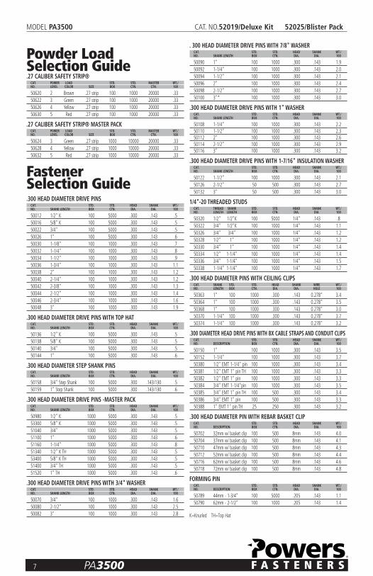
Powder Load Selection Guide.27 CALIBER SAFETY STRIP®CAT. POWER LOAD STD. STD. MASTER WT./NO. LEVEL COLOR SIZE BOX CTN. CTN. 100
50620 2 Brown .27 strip 100 1000 20000 .3350622 3 Green .27 strip 100 1000 20000 .3350626 4 Yellow .27 strip 100 1000 20000 .3350630 5 Red .27 strip 100 1000 20000 .33
.27 CALIBER SAFETY STRIP® MASTER PACKCAT. POWER LOAD STD. STD. MASTER WT./NO. LEVEL COLOR SIZE BOX CTN. CTN. 100
50624 3 Green .27 strip 1000 10000 20000 .3350628 4 Yellow .27 strip 1000 10000 20000 .3350632 5 Red .27 strip 1000 10000 20000 .33
Fastener Selection Guide.300 HEAD DIAMETER DRIVE PINSCAT. STD. STD. HEAD SHANK WT./NO. SHANK LENGTH BOX CTN. DIA. DIA. 100
50012 1/2" K 100 5000 .300 .143 .550016 5/8" K 100 5000 .300 .143 .550022 3/4" 100 5000 .300 .143 .550026 1" 100 5000 .300 .143 .650030 1-1/8" 100 1000 .300 .143 .750032 1-1/4" 100 1000 .300 .143 .850034 1-1/2" 100 1000 .300 .143 .950036 1-3/4" 100 1000 .300 .143 1.150038 2" 100 1000 .300 .143 1.250040 2-1/4" 100 1000 .300 .143 1.250042 2-3/8" 100 1000 .300 .143 1.350044 2-1/2" 100 1000 .300 .143 1.450046 2-3/4" 100 1000 .300 .143 1.650048 3" 100 1000 .300 .143 1.9
.300 HEAD DIAMETER DRIVE PINS WITH TOP HATCAT. STD. STD. HEAD SHANK WT./NO. SHANK LENGTH BOX CTN. DIA. DIA. 100
50136 1/2" K 100 5000 .300 .143 .550138 5/8" K 100 5000 .300 .143 .550140 3/4" 100 5000 .300 .143 .550144 1" 100 5000 .300 .143 .6
.300 HEAD DIAMETER STEP SHANK PINSCAT. STD. STD. HEAD SHANK WT./NO. SHANK LENGTH BOX CTN. DIA. DIA. 100
50158 3/4" Step Shank 100 5000 .300 .143/130 .550159 1" Step Shank 100 5000 .300 .143/130 .6
.300 HEAD DIAMETER DRIVE PINS -MASTER PACKCAT. STD. STD. HEAD SHANK WT./NO. SHANK LENGTH BOX CTN. DIA. DIA. 100
50980 1/2" K 1000 5000 .300 .143 .553300 5/8" K 1000 5000 .300 .143 .551040 3/4" 1000 5000 .300 .143 .5 51100 1" 1000 5000 .300 .143 .651160 1-1/4" 1000 5000 .300 .143 .851340 1/2" K TH 1000 5000 .300 .143 .553400 5/8" K TH 1000 5000 .300 .143 .551400 3/4" TH 1000 5000 .300 .143 .551520 1" TH 1000 5000 .300 .143 .6
.300 HEAD DIAMETER DRIVE PINS WITH 3/4" WASHERCAT. STD. STD. HEAD SHANK WT./NO. SHANK LENGTH BOX CTN. DIA. DIA. 100
50070 3/4" 100 1000 .300 .143 1.650080 2-1/2" 100 1000 .300 .143 2.550082 3" 100 1000 .300 .143 2.8
. 300 HEAD DIAMETER DRIVE PINS WITH 7/8" WASHERCAT. STD. STD. HEAD SHANK WT./NO. SHANK LENGTH BOX CTN. DIA. DIA. 100
50090 1" 100 1000 .300 .143 1.950092 1-1/4" 100 1000 .300 .143 2.050094 1-1/2" 100 1000 .300 .143 2.150096 2" 100 1000 .300 .143 2.450098 2-1/2" 100 1000 .300 .143 2.750100 3"* 100 1000 .300 .143 3.0
.300 HEAD DIAMETER DRIVE PINS WITH 1" WASHERCAT. STD. STD. HEAD SHANK WT./NO. SHANK LENGTH BOX CTN. DIA. DIA. 100
50108 1-1/4" 100 1000 .300 .143 2.250110 1-1/2" 100 1000 .300 .143 2.350112 2" 100 1000 .300 .143 2.650114 2-1/2" 100 1000 .300 .143 2.950116 3" 100 1000 .300 .143 3.2
.300 HEAD DIAMETER DRIVE PINS WITH 1-7/16" INSULATION WASHERCAT. STD. STD. HEAD SHANK WT./NO. SHANK LENGTH BOX CTN. DIA. DIA. 100
50122 1-1/2" 100 1000 .300 .143 2.150126 2-1/2" 50 500 .300 .143 2.750132 3" 50 500 .300 .143 3.0
1/4"-20 THREADED STUDSCAT. THREAD SHANK STD. STD. HEAD SHANK WT./NO. LENGTH LENGTH BOX CTN. DIA. DIA. 100
50320 1/2" 1/2"K 100 5000 1/4" .143 .850322 3/4" 1/2"K 100 1000 1/4" .143 1.150326 3/4" 3/4" 100 1000 1/4" .143 1.250328 1/2" 1" 100 1000 1/4" .143 1.250330 3/4" 1" 100 1000 1/4" .143 1.450334 1/2" 1-1/4" 100 1000 1/4" .143 1.450336 3/4" 1-1/4" 100 1000 1/4" .143 1.550338 1-1/4" 1-1/4" 100 1000 1/4" .143 1.7
.300 HEAD DIAMETER PINS WITH CEILING CLIPSCAT. SHANK STD. STD. HEAD SHANK WIRE WT./NO. LENGTH BOX CTN. DIA. DIA. HOLE 100
50363 1" 100 1000 .300 .143 0.278" 3.450364 1" 100 1000 .300 .143 0.278" 3.550368 1" 100 1000 .300 .143 0.278" 3.050370 1-1/4" 100 1000 .300 .143 0.278" 3.750374 1-1/4" 100 1000 .300 .143 0.278" 3.2
.300 DIAMETER HEAD DRIVE PINS WITH BX CABLE STRAPS AND CONDUIT CLIPSCAT. STD. STD. HEAD SHANK WT./NO. DESCRIPTION BOX CTN. DIA. DIA. 100
50150 1" 100 1000 .300 .143 3.550152 1-1/4" 100 1000 .300 .143 3.750380 1/2" EMT 1-1/4" pin 100 1000 .300 .143 3.450381 1/2" EMT 1" pin TH 100 1000 .300 .143 3.350382 1/2" EMT 1" pin 100 1000 .300 .143 3.350384 3/4" EMT 1-1/4"pin 100 1000 .300 .143 3.550385 3/4" EMT 1" pin TH 100 500 .300 .143 3.450386 3/4" EMT 1" pin 100 500 .300 .143 3.350388 1" EMT 1" pin TH 25 250 .300 .143 3.2
.300 HEAD DIAMETER PIN WITH REBAR BASKET CLIPCAT. STD. STD. HEAD SHANK WT./NO. DESCRIPTION BOX CTN. DIA. DIA. 100
50702 32mm w/ basket clip 100 500 8mm .143 4.050704 37mm w/ basket clip 100 500 8mm .143 4.150710 47mm w/ basket clip 100 500 8mm .143 4.350712 52mm w/ basket clip 100 500 8mm .143 4.450716 62mm w/ basket clip 100 500 8mm .143 4.650718 72mm w/ basket clip 100 500 8mm .143 4.8
FORMING PINCAT. STD. STD. HEAD SHANK WT./NO. DESCRIPTION BOX CTN. DIA. DIA. 100
50789 44mm - 1-3/4" 100 5000 .205 .143 1.150790 62mm - 2-1/2" 100 1000 .205 .143 1.4
K=Knurled TH=Top Hat

8 PA3500
MODEL PA3500 CAT. NO.52019/Deluxe Kit 52025/Blister Pack
Safety PrecautionsSafety is your primary responsibility when operating anypowder actuated tool. You must read and understandthe contents of this manual. You must be familiar withall functional and safety requirements of the tool. It isyour responsibility to obtain proper training and aPowers Fasteners operator card prior to using this tool in compliance with the current American NationalStandard A10.3 Safety Requirements for PowderActuated Fastening Systems and the FederalOccupational Safety and Health AdministrationStandards (OSHA). Existing state or local regulationsshould also be followed. When using this tool, you musthave the qualified operators card in your possession.Revocation of card - Failure to comply with any of therules and regulations for safe operation of powderactuated tools shall be cause for the immediaterevocation of your qualified operator card.
The following is a summary of safety precautions to be followed when operating a Powers Fastenerspowder actuated tool. Failure to follow these safetyinstructions can result in serious injury or death tooperators or bystanders.
PRIOR TO OPERATING THE TOOL1. Warning signs should always be posted within the area
in which a powder actuated tool is to be used. Thesesigns should be at least 8" x 10" in size with boldfacetype that is not less than 1" in height. The sign shouldstate "Powder Actuated Tool In Use".
2. Approved safety goggles should always be worn byoperator or bystander, to protect their eyes from flyingparticles. Hearing protection should always be worn bythe operator and bystanders when using a powderactuated tool. Other personal safety protection asrequired should also be used.
3. Never modify or fabricate parts for use in your Powerstool. Use only Powers fasteners, loads, and tool parts.
4. Hands or other body parts must never be placed in frontof muzzle/barrel. Accidental discharge can cause pistonand/or fastener to pass through the operator’s hand.
5. Never compress the tool against any part of the body.Serious injury or death may result in the event of anaccidental discharge.
6. Always point tool in a safe direction at all times.7. Use the tool for its intended purpose only.
PREPARATION FOR LOADING THE TOOL1. Tools must be checked prior to operating to make sure
they are not fully or partially loaded with a powder loador fastener.
2. To insure safe operation, perform the daily function testdescribed in this manual. Be sure the tool is not loadedprior to performing this test.
3. Do not operate this tool unless all its parts are in placeand operating appropriately. Never attempt to use amalfunctioning tool. Call 1-800-524-3244 for assistance.
4. Never guess about the suitability of a base material. Ifyou are uncertain about the suitability of a basematerial, perform a center punch test.
5. Do not operate the tool until you learn and understandthe color code / numbering system used to identify thepower level of powder loads.
OPERATING THE TOOL1. Only use fasteners and powder loads designed for this
tool as supplied by Powers Fasteners.2. Do not use powder actuated tools in a flammable or an
explosive atmosphere.3. Do not fire a tool without a fastener. The piston will
impact the work surface possibly causing serious injuryto the operator or bystanders along with damage tothe tool.
4. Do not load the tool until you are ready to make afastening. Check the power load level before inserting itinto the tool chamber.
5. Fastener must be loaded prior to loading the powderload, to prevent injury to operator or bystander in theevent of an accidental discharge.
6. Do not close tool against work surface. The tool shouldbe manually closed, with hand away from muzzle/barrelto prevent accidental discharge.
7. Hold the tool perpendicular to the work surface at alltimes. Use a spall guard wherever possible. This will limitthe possibility of fastener ricochet which could causeserious injury or death to the operator or bystanders.
8. Always perform a test fastening with the lightest loadlevel designed for use in the tool. If the lightest loadfails to set the fastener, try the next highest load untilthe proper level is attained. Failure to follow thisprocedure may cause the fastener to be overpowered.If this occurs, the fastener may fully penetrate the base material causing serious injury or death tosomeone. Overpowering the fastener can also damagethe tool, creating a safety hazard to both the operatoror bystanders.
9. Do not fasten into cast iron, tile, glass, or other types ofbrittle materials. These materials can shatter and createsharp fragments which may cause injury.
10. Do not fire tool within 3" (three inches) of the edge ofa concrete base material or within 1/2" (one-half inch)of the edge of a steel base material.
11. Do not attempt to install a fastener closer than 3"(three inches) to another previously inserted fastener inconcrete or 1-1/2" (one and one-half inch) in steel.
12. Do not fasten into a concrete base material less than 3times as thick as the fastener penetration or into a steelbase material thinner than 1/8”.

13. Never attempt to install a fastener in a cracked orspalled area in concrete. Place fastener at least 3”(three inches) away from a spalled area to prevent thepossibility of the fastener bending and striking anoperator or bystander.
14. Do not attempt to install fasteners in areas that havebeen welded or cut with a torch as these proceduresmay have caused local hardening of the steel.
15. Do not fasten through a predrilled hole unless properguidance is provided.
16. If you decide not to make a fastening after the tool hasbeen loaded, you must always remove the powder loadfirst followed by the fastener.
17. Never attempt to override the safety features of this tool.
HANDLING THE TOOL AND POWDER LOADS1. Never leave a loaded tool unattended. Once the tool
is loaded, make the fastening immediately or unloadthe tool.
2. Always unload the tool before work breaks, changingparts, cleaning or servicing, and when storing.
3. To prevent accidental discharge of loads, never carry thepowder loads in the same container as the fasteners orother hard objects.
4. Always store the powder loads in the containers
provided or in an enclosure provided for them. Never intermix the various power levels. Keep themsegregated in clearly identified containers.
5. Powder loads should never be used in firearms. They are normally more powerful that the cartridges suppliedwith the firearms.
6. Powder actuated tools and powder loads should alwaysbe stored under lock and key. Tools must be unloadedwhen not in use.
TOOL MALFUNCTION1. In the event that a load fails to discharge after the
trigger is pulled, the tool must be kept depressedagainst the work surface for a minimum of 30 (thirty)seconds in case of a delayed load discharge. Thencarefully remove the entire load strip. and dispose of itin a can of water or other nonflammable liquid. Neverattempt to force or pry a load out of a tool chamber.
2. Never discard unfired powder loads into a trash container.3. Do not attempt to unload or disassemble a jammed,
stuck or broken tool as improper handling may cause itto discharge and strike operator and/or bystander. Ajammed tool must be pointed in a safe direction at alltimes. Tag the tool and lock it up. Call your PowersFasteners representative for proper assistance.
9 PA3500
MODEL PA3500 CAT. NO.52019/Deluxe Kit 52025/Blister Pack

Tool OperationCAUTION:— Be sure to read and understand all of the safety precautions and training inthis manual before attempting to operate the tool. (Check to be sure the tool is not loaded, thepiston moves freely within the barrel, and no foreign objects or fasteners are in the barrel.)Perform the daily function test before using the tool.
OPERATION1. Always load the fastener before inserting powder load to prevent injury to the operator or
bystanders in the event of an accidental discharge. Place the fastener, point out, into the end ofthe guide until the fluted tip fits inside. Do not use excessive force when inserting the fastener. Ifexcessive force is required, stop and determine why the fastener can not be inserted. Correct theproblem before proceeding.Note: Do not use fasteners longer than 3" as listed in the fastener selection section of this manual.
2. Always point the tool in a safe direction away from bystanders and the operator. In onemovement, slide the barrel forward then close it against the stop. The barrel should be pulledfully forward to reset the piston for the next fastening. Loss of power may result from an im -properly positioned piston.Do not attempt to close the tool by exerting force on the front of the barrel. Never place yourfingers or hands over muzzle end of the tool. The safe position for hands and fingers are asshown in the diagram. Hands must never be placed in front of the tool muzzle or barrel. In the event of an accidental discharge, the piston and/or fastener can pass through the operator's hand.
3. Insert the powder load strip into the bottom of the tool handle starting with the lowest powerlevel, 3/Green. The strip should be inserted completely and should be flush with the bottom ofthe handle. Always insert the strip from the bottom of the handle. Set the power adjustmentlevel to 1. If the fastener does not fully set in the base material increase the power level to 2and so on until proper penetration is achieved. If proper penetration is not achieved using3/green charge and power level 3, the next strongest charge should be used. Operator shouldthen follow the above procedure regarding power level adjustment until proper penetration is achieved.Note: Over driving or over powering a fastener can cause a safety hazard.
4. To make a fastening, place the tool against the work surface. Hold the tool firmly with twohands and completely depress the barrel. Then squeeze the trigger. Always hold the toolperpendicular to the work surface. Hold the tool firmly against the work surface to avoidexcessive recoil. Never depress the tool against anything except the work surface. Note: In the event that the load does not discharge after the trigger is pulled, continue to holdthe tool depressed against the work surface for at least 30 (thirty) seconds in case of a delayedload discharge. Then carefully remove the entire load strip and dispose of it in a can of water orother non flammable liquid. Never attempt to force or pry a load out of a tool chamber. Do notdiscard unfired loads into a trash container.
5. To prepare for the next fastening, point the tool in a safe direction. Always insert a new fastenerbefore loading or advancing the powder load strip. Insert the fastener as described in step 1.Once the fastener is inserted, cycle the tool as described in step 2. Repeat this procedure forsubsequent fastenings. When the ten load strip has been completely fired, remove it by pulling itfrom the top of the tool body.Note: Do not attempt to unload or disassemble a jammed, stuck or broken tool as improperhandling may cause it to discharge and strike the operator and/or bystander. A jammed toolmust be pointed in a safe direction at all times. Tag the tool and lock it up. Call your PowersFasteners representative for proper assistance.
10 PA3500
MODEL PA3500 CAT. NO.52019/Deluxe Kit 52025/Blister Pack
R3500

Proper Maintenance and Cleaning MAKE SURE THE TOOL IS NOT LOADED. BE SURE THE TOOL IS NOT HOT PRIOR TO ATTEMPTING DISASSEMBLY OR CLEANING.
DAILY FUNCTION TESTCheck the functioning of the tool, without a powder load or fastener in the tool, by pushing down against the worksurface, pulling the trigger, and releasing the tool from the work surface. Function the unloaded tool several times andinsure that the breech parts and firing mechanism operate freely before fastening with the tool.Your Powers Fasteners Authorized representative should be asked to assist the first time you disassemble and cleanyour tool. If you ever have any trouble reassembling the tool, or have any doubt about worn parts, call your PowersFasteners Authorized Powder Distributor.
CLEANINGAIl parts should be cleaned with detergent oil and the wire brushes supplied with your tool kit. Remove heavy dirtbuildup with the brush. After cleaning with oil, all parts should be wiped thoroughly dry. Excess oil will tend to collectdirt and dust. Wear eye protection when cleaning the tool.The piston rod, barrel assembly, and receiver should all be cleaned of excess dirt on a daily basis. Check the conditionof the piston for damage from wear and deformation. To maintain this tool in good working condition, it is necessary to disas semble and clean the entire tool if dirt is evidentin the breech face, or if the tool appears to lose power. All parts should be cleaned with oil and wire brushes. Removeheavy dirt. All parts should be wiped thoroughly dry after cleaning with oil.General tool mainte nance should be performed at six month intervals or more frequently as required by the frequencyof tool use.
11 PA3500
MODEL PA3500 CAT. NO.52019/Deluxe Kit 52025/Blister Pack

PA3500™ Spare Parts ListingCAT. NO. NO. DESCRIPTION
52166 1 Stabilizer52110 2 Baseplate 2/S13-Standard52120 3 Shear Clip52108 4 Guide 2/F-3-Standard52103 5* Piston Flat End w/ring -Standard52107 6 Piston Ring52161 7* Piston Guide52161 8* Regulation Pin52161 9* 1/8" Steel Ball52161 10* C Clip for Piston Guide52112 11 Piston Stop52163 12* Steel Liner Assembly52153 13 Pressure Pin
14 Front Allen Cap Screw (2) M6x2552122 15 Steel Ball52136 16 Annular Ball Spring52140 17 Ball
* New PA3500™ parts
CAT. NO. NO. DESCRIPTION
52140 18 Spring52165 19* Housing/Adjuster Kit52165 20* Decorative Bullet Head52165 21* Regulation Knob52165 22* Snap Spring52165 23* Snap for Knob Head52165 24* Knob Fixer52165 25* Fixing Pin for Knob52165 26* Fixing Pin for Knob Fixer52129 27 Threaded Pin52146 28 Sear52134 29 Sear Spring52178 30 Spring Guide52148 31** Firing Pin52181 32** Spring Detent52181 33** Firing Pin Return Spring52181 34** Firing Pin Nut
**Firing Pin Assembly Includes Item Nos. 31-34
CAT. NO. NO. DESCRIPTION
52172 35 Retaining Ring52125 36 Advance Lever Kit52125 37 Advance Lever Spring52125 3852125 3952125 4052144 41 Firing Pin Spring Kit52144 4252150 43 End Cap
44 Release Lever Pin52158 45 Front Cap Screw (2)
46 Release Lever47 Trigger Return Spring48 Compression Spring49 Support Strip Assembly50 Handle Allen Screw51 Rubber Grip
52159 52*** Adjuster Kit
***Includes Item Nos. 20-26
12 PA3500
MODEL PA3500 CAT. NO.52019/Deluxe Kit 52025/Blister Pack

TroubleshootingALWAYS CHECK INSTRUCTION MANUAL FOR PROPER ASSEMBLY OF PARTSPROBLEM POSSIBLE CAUSE SOLUTION
Fastener Overdriving Power level too high / Pin too short Use a lower powder load level number or a longer pinSoft base material Check base material suitability section
Tool does not fire Tool not depressed completely See "Tool does not depress completely" section belowFiring pin damaged Replace damaged part(s)
Tool does not depress completely Damaged firing pin parts, ejector, Check the parts for damage or improper assemblyetc. Parts assembled improperly
Power reduction or inconsistent Barrel is not pulled fully Barrel must be pulled out completely to properlyfastener penetra tion forward when cycling tool. reset the piston
Worn or damaged piston Replace piston or piston ringor piston ring
Load strip cannot be Improper loading Insert strip from the bottom of the tool handleinserted into tool
Wrong caliber strip Use proper stripLoad strip will not advance Worn advance lever guide Replace advance lever guide.
This should be performed by qualified individualsLoad will not fire when Tool is not fully depressed Follow safety procedure for misfired load thentrigger is pulled attempt to fully depress tool before pulling triggerLoad will not fire when Load is already fired Cycle tooltool is fully depressedand trigger is pulled
Load misfire Follow safety procedureBroken firing pin Replace firing pin nut.
This should be performed by qualified individualsBroken or missing Replace firing pin nut. This firing pin nut should be
performed by qualified individualsTool cannot be opened or cycled Lack of proper cleaning Clean tool thoroughly
Damaged or bent piston Remove and replace pistonBroken or damaged parts Tag tool with warning "Defective - Do Not Use" place
in locked container and contact your Powers Fasteners Authorized representative for service
Piston stuck in the Piston has been overdriven and is Tap the piston against a hard surfaceforward position jammed against piston reset pinChipped or damaged piston Tool not held on work surface Machine piston as shown on page 21.
squarely. This allows the piston to Piston regrinding may be performed only byslip off the head of the pin and qualified individualscause damage to the piston
Piston guide will not Bent shear clip Remove and replace shear clipopen easily
Excessive buildup of dirt Disassemble and clean toolPiston stop is damaged Replace piston stopForeign material jammed Disassemble and remove foreign particlesbetween the piston guide and steel liner assembly
Piston guide opens Annular ball spring or Remove and replace with a new spring and/or balltoo easily steel annular ball have worn
13 PA3500
MODEL PA3500 CAT. NO.52019/Deluxe Kit 52025/Blister Pack

REPLACING OR REPAIRING THE PISTONThe piston is an expendable part and must be replaced periodically. Typical signs of a worn outpiston are: breaking, bending or mushrooming.Prior to servicing the tool make sure there is no powder load in the tool. Use caution and donot lose or damage any tool parts.
1. Using a pin, lift the end of the annular ball spring and rotate toward the top of the tool body.Pull the piston stop back and out of the tool.
2. Slide the piston guide and baseplate assembly out of the tool.3. Using a fastener, pry the shear clip off the baseplate. Replace the shear clip if it is damaged.4. Remove the baseplate from the piston guide, then pull the piston out of the guide.
REASSEMBLY:5. Tilt the baseplate and slide the fastener guide out. Press the guide out of the baseplate using a
piston if it does not slide out freely. Replace the guide if it is damaged.6. Clean the piston using a wire brush. Inspect it for worn or damaged piston ring, chipped end, or
bending. Apply lubricant to the piston shank to minimize piston sticking from an overdrive con -dition. Wipe the piston dry.
7. If a piston tip is damaged, it can be shortened a maximum of 0.20 inches. The tip of the pistonshould be ground flat and at 90 degrees to the shank of the piston. The cham fer of the pistonmust also be reground as shown. Piston grinding should be performed by qualified per sonnelusing the proper equipment.
8. Press the piston into the end of the piston guide. Be sure to push it all the way back into theguide. Ensure piston is positioned correctly in piston guide.
9. Insert the fastener guide into the baseplate.10. Align the groove in both the piston guide and baseplate. Slide the baseplate (with fastener
guide) onto the piston guide. Press the shear clip into place. Insert the piston guide andbaseplate assembly into the liner in the tool body. Be sure to align the groove with the openingfor the piston stop.
11. Replace the piston stop and rotate the annular spring into place.Upon reassembly of the tool perform the following test. Depress the tool against a flat, hardsurface and pull the trigger. The barrel assembly should slide smoothly inside the tool housingassembly. The firing pin should release after the trigger has been pulled.
CAUTION:THIS TEST SHOULD BE PERFORMED WITHOUT A PIN ORPOWDER LOAD IN THE TOOL.
14 PA3500
MODEL PA3500 CAT. NO.52019/Deluxe Kit 52025/Blister Pack
1
2
3
4
6
5
10°
0.120"
7
8
9
10
11
�

15 PA3500
MODEL PA3500 CAT. NO.52019/Deluxe Kit 52025/Blister Pack
TRIM ALONG DOTTED LINE, PLACE IN ENVELOPE, ADDRESS AS SHOWN AND AFFIX POSTAGE
�
���Check the correct answer.1 It is necessary to read the Operator’s
Manual prior to operating a PowersFasteners low velocity tool.�� True �� False
2 When fastening into concrete, the basematerial should be greater than theshank penetration by at least: �� 1 time �� 2 times �� 3 times
3 When operating a powder actuated tool,your hand should never be placed: �� around the tool body �� in front of the tool muzzle�� over the tool handle
4 To determine the suitability of a base material, use the fastener as a center punch.
• If the fastener is blunted, do not fasten;the material is too:�� soft �� hard �� brittle
• If the fastener penetrates easily, do notfasten; the material is too:�� soft �� hard �� brittle
• If the material cracks or shatters, do notfasten; the material is too:�� soft �� hard �� brittle
5 Unsafe applications for powder actuated tools may be caused by which of the following?�� a soft base material�� improper powder load�� fastening too close to
an unsupported edge�� a malfunctioning tool�� fastening into a spalled area�� fastening through a pre-existing hole�� all of the above
6 Which one of the following buildingmaterials is not suitable as a receivingmaterial (base material) for powderactuated fasteners?�� sheet rock�� wood�� fiberglass�� sheet metal�� all of the above
7 When considering the safety of aparticular application, the operator must think about:�� the base material�� the powder load power level�� the operator’s safety�� the safety of bystanders
and fellow workers�� all of the above
8 The proper loading procedure is: insertfastener first, powder load second. Thefastener should always be placed in thetool prior to the load.�� True �� False
9 Which one of the following materials is usually suitable for powder actuated fastenings?�� poured concrete�� hollow tile�� surface hardened steel�� glazed brick
10 In concrete, a fastener should be drivenno closer to an unsupported edge than:�� 1/2" �� 1-1/2" �� 3"
11 Fishhooking is a condition which can occurwhen a powder actuated fastener strikes apiece of hard aggregate or very hardconcrete, bends and comes out of thework surface. A fishhook can cause aserious injury or death.�� True �� False
12 Placing a hand over the muzzle bushingof a loaded tool can result in seriousinjury from piston overdrive or anescaping fastener if the tool is dischargedaccidentally.�� True �� False
13 Piston overdrive is caused byoverpowering of the tool or bydischarging the tool against a soft surface.�� True �� False
14 Malfunctioning tools cannot be used and must be removed from service immediately.�� True �� False
15 After conducting a Center Punch Test, thebest way to check the base material is toset several fasteners using the leastpowerful load.�� True �� False
16 Safety goggles and hearing protectionshould not be worn by the operator andany necessary bystanders when using the tool.�� True �� False
17 A powder actuated tool cannot be safely used in an explosive or flammable atmosphere.�� True �� False
18 List the proper powder load level number(1-6) next to each color listed.Red ___ Brown ___Green ___ Yellow ___Gray ___ Purple ___
19 The weakest power level should be usedwhen making the first fastening.�� True �� False
20 You can fasten into weld areas of steel.�� True �� False
PA3500• The proper procedure if a powder load
fails to ignite is to hold the tool againstthe work surface and wait 30 seconds,then proceed exactly as directed in theOperator’s Manual.�� True �� False
• Powers Fasteners powder loads for thePA3500™ are .27 caliber rim fire shortcrimped cartridges in plastic magazines.No other powder load may be used in this tool.�� True �� False
• Operators should never compress thePA3500™ or any other powder actuatedtool against any part of their body.�� True �� False
• If a shear clip for the PA3500™ becomesdeformed, simply remove it, ham mer itback into shape and replace it in the tool.�� True �� False
OPERATOR’S NAME DATE
HOME ADDRESS
AGE DATE OF BIRTH
COMPANY NAME
COMPANY ADDRESS
COMPANY PHONE
SIGNATURE DATE
QUALIFIED TOOL OPERATOR EXAMINATION

16 PA3500
MODEL PA3500 CAT. NO.52019/Deluxe Kit 52025/Blister Pack
LICENSE AND WARRANTY ACTIVATIONTHE PA3500™ TOOL IS WARRANTED FOR 5 YEARS FROM DATE OF PURCHASE.
I certify that I have read and understand the PA3500™ Tool Operating Instruction Manual and have taken the Operator’s exam.I understand the importance of following all safety procedures and that failure to read, comprehend, and follow the detailedrules and warnings regarding the safe operation of powder actuated tools can result in serious injury or death to the tooloperator or bystanders. I agree to conform to all the rules and regulations regarding the use of powder actuated tools.(Please print clearly)
THE SERIAL NUMBER ON MY TOOL IS:
PLEASE SEND MY TOOL LICENSE TO:
NAME
ADDRESS
CITY STATE ZIP PHONE
M A I L T O : Tool License CoordinatorPowers Fasteners, Inc.2 Powers LaneBrewster, NY 10509
TRIM ALONG DOTTED LINE, PLACE IN ENVELOPE, ADDRESS AS SHOWN AND AFFIX POSTAGE
�