1962- 1967 chevy nova pro-touring front suspension ... · page 1 of 10 1962- 1967 chevy nova...
TRANSCRIPT
Page 1 of 10
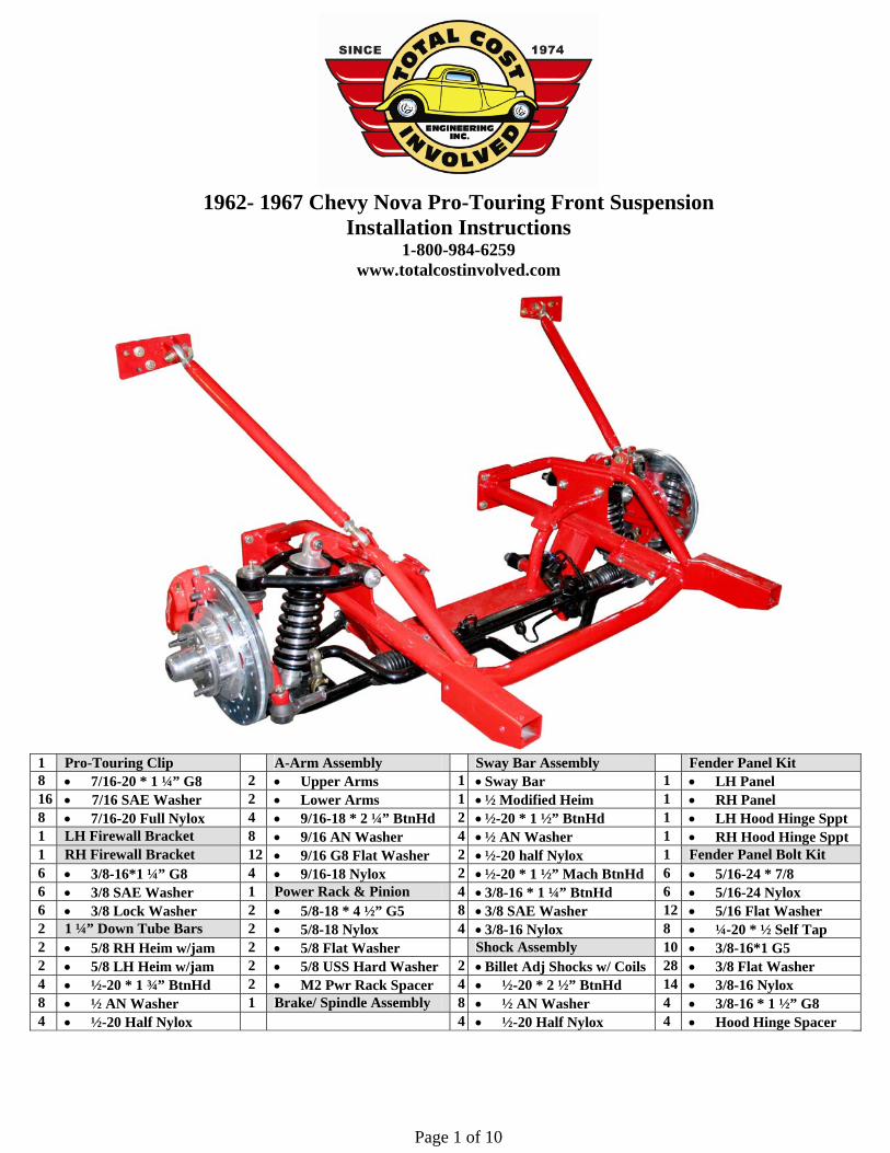
1962- 1967 Chevy Nova Pro-Touring Front Suspension
Installation Instructions 1-800-984-6259
www.totalcostinvolved.com
1 Pro-Touring Clip A-Arm Assembly Sway Bar Assembly Fender Panel Kit 8 • 7/16-20 * 1 ¼” G8 2 • Upper Arms 1 • Sway Bar 1 • LH Panel 16 • 7/16 SAE Washer 2 • Lower Arms 1 • ½ Modified Heim 1 • RH Panel 8 • 7/16-20 Full Nylox 4 • 9/16-18 * 2 ¼” BtnHd 2 • ½-20 * 1 ½” BtnHd 1 • LH Hood Hinge Sppt 1 LH Firewall Bracket 8 • 9/16 AN Washer 4 • ½ AN Washer 1 • RH Hood Hinge Sppt 1 RH Firewall Bracket 12 • 9/16 G8 Flat Washer 2 • ½-20 half Nylox 1 Fender Panel Bolt Kit 6 • 3/8-16*1 ¼” G8 4 • 9/16-18 Nylox 2 • ½-20 * 1 ½” Mach BtnHd 6 • 5/16-24 * 7/8 6 • 3/8 SAE Washer 1 Power Rack & Pinion 4 • 3/8-16 * 1 ¼” BtnHd 6 • 5/16-24 Nylox 6 • 3/8 Lock Washer 2 • 5/8-18 * 4 ½” G5 8 • 3/8 SAE Washer 12 • 5/16 Flat Washer 2 1 ¼” Down Tube Bars 2 • 5/8-18 Nylox 4 • 3/8-16 Nylox 8 • ¼-20 * ½ Self Tap 2 • 5/8 RH Heim w/jam 2 • 5/8 Flat Washer Shock Assembly 10 • 3/8-16*1 G5 2 • 5/8 LH Heim w/jam 2 • 5/8 USS Hard Washer 2 • Billet Adj Shocks w/ Coils 28 • 3/8 Flat Washer 4 • ½-20 * 1 ¾” BtnHd 2 • M2 Pwr Rack Spacer 4 • ½-20 * 2 ½” BtnHd 14 • 3/8-16 Nylox 8 • ½ AN Washer 1 Brake/ Spindle Assembly 8 • ½ AN Washer 4 • 3/8-16 * 1 ½” G8 4 • ½-20 Half Nylox 4 • ½-20 Half Nylox 4 • Hood Hinge Spacer
Page 2 of 10
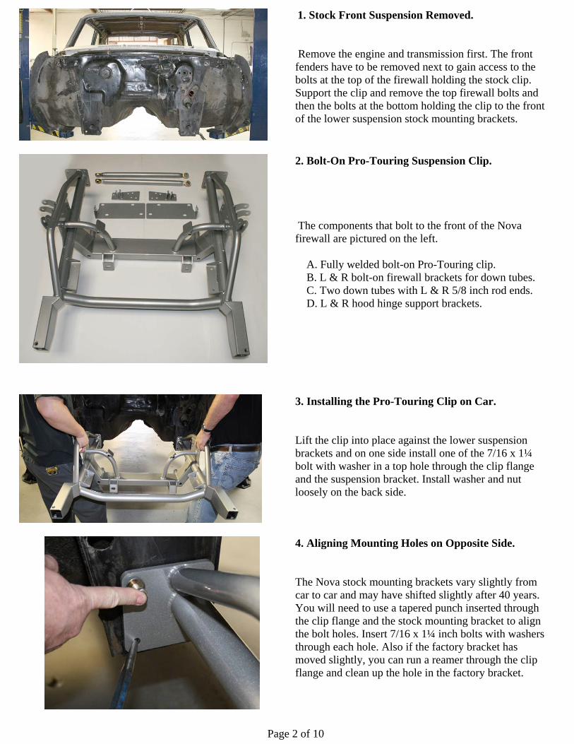
1. Stock Front Suspension Removed. Remove the engine and transmission first. The front fenders have to be removed next to gain access to the bolts at the top of the firewall holding the stock clip. Support the clip and remove the top firewall bolts and then the bolts at the bottom holding the clip to the front of the lower suspension stock mounting brackets.
2. Bolt-On Pro-Touring Suspension Clip. The components that bolt to the front of the Nova firewall are pictured on the left. A. Fully welded bolt-on Pro-Touring clip. B. L & R bolt-on firewall brackets for down tubes. C. Two down tubes with L & R 5/8 inch rod ends. D. L & R hood hinge support brackets.
3. Installing the Pro-Touring Clip on Car. Lift the clip into place against the lower suspension brackets and on one side install one of the 7/16 x 1¼ bolt with washer in a top hole through the clip flange and the suspension bracket. Install washer and nut loosely on the back side.
4. Aligning Mounting Holes on Opposite Side. The Nova stock mounting brackets vary slightly from car to car and may have shifted slightly after 40 years. You will need to use a tapered punch inserted through the clip flange and the stock mounting bracket to align the bolt holes. Insert 7/16 x 1¼ inch bolts with washers through each hole. Also if the factory bracket has moved slightly, you can run a reamer through the clip flange and clean up the hole in the factory bracket.
Page 3 of 10
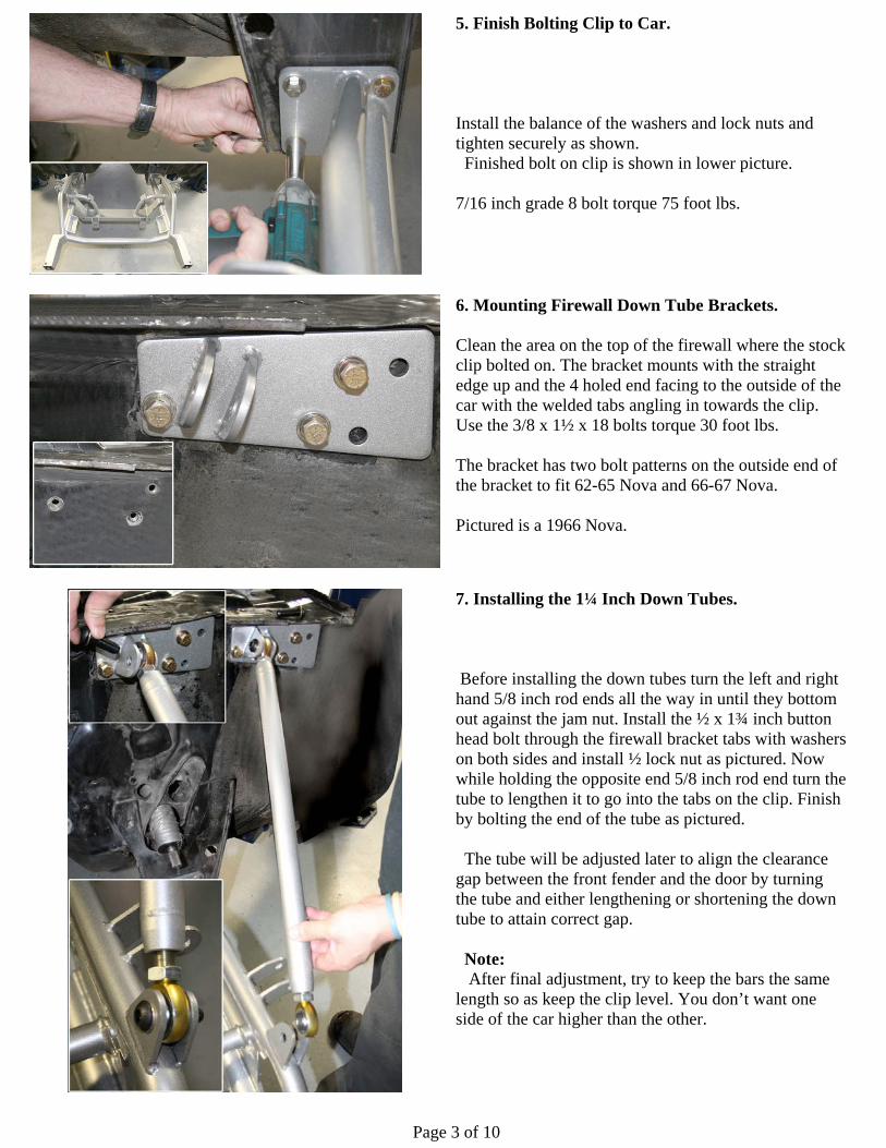
5. Finish Bolting Clip to Car. Install the balance of the washers and lock nuts and tighten securely as shown. Finished bolt on clip is shown in lower picture. 7/16 inch grade 8 bolt torque 75 foot lbs.
6. Mounting Firewall Down Tube Brackets. Clean the area on the top of the firewall where the stock clip bolted on. The bracket mounts with the straight edge up and the 4 holed end facing to the outside of the car with the welded tabs angling in towards the clip. Use the 3/8 x 1½ x 18 bolts torque 30 foot lbs. The bracket has two bolt patterns on the outside end of the bracket to fit 62-65 Nova and 66-67 Nova. Pictured is a 1966 Nova.
7. Installing the 1¼ Inch Down Tubes. Before installing the down tubes turn the left and right hand 5/8 inch rod ends all the way in until they bottom out against the jam nut. Install the ½ x 1¾ inch button head bolt through the firewall bracket tabs with washers on both sides and install ½ lock nut as pictured. Now while holding the opposite end 5/8 inch rod end turn the tube to lengthen it to go into the tabs on the clip. Finish by bolting the end of the tube as pictured. The tube will be adjusted later to align the clearance gap between the front fender and the door by turning the tube and either lengthening or shortening the down tube to attain correct gap. Note: After final adjustment, try to keep the bars the same length so as keep the clip level. You don’t want one side of the car higher than the other.
Page 4 of 10
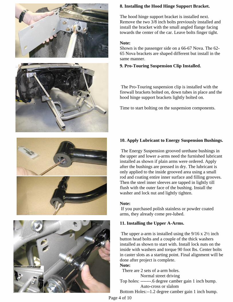
8. Installing the Hood Hinge Support Bracket. The hood hinge support bracket is installed next. Remove the two 3/8 inch bolts previously installed and install the bracket with the small angled flange facing towards the center of the car. Leave bolts finger tight. Note: Shown is the passenger side on a 66-67 Nova. The 62-65 Nova brackets are shaped different but install in the same manner.
9. Pro-Touring Suspension Clip Installed. The Pro-Touring suspension clip is installed with the firewall brackets bolted on, down tubes in place and the hood hinge support brackets lightly bolted on. Time to start bolting on the suspension components.
10. Apply Lubricant to Energy Suspension Bushings. The Energy Suspension grooved urethane bushings in the upper and lower a-arms need the furnished lubricant installed as shown if plain arms were ordered. Apply after the bushings are pressed in dry. The lubricant is only applied to the inside grooved area using a small rod and coating entire inner surface and filling grooves. Then the steel inner sleeves are tapped in lightly till flush with the outer face of the bushing. Install the washer and lock nut and lightly tighten. Note: If you purchased polish stainless or powder coated arms, they already come pre-lubed.
11. Installing the Upper A-Arms. The upper a-arm is installed using the 9/16 x 2½ inch button head bolts and a couple of the thick washers installed as shown to start with. Install lock nuts on the inside with washers and torque 90 foot lbs. Center bolts in caster slots as a starting point. Final alignment will be done after project is complete. Note: There are 2 sets of a-arm holes. Normal street driving Top holes: -------.6 degree camber gain 1 inch bump. Auto-cross or slalom Bottom Holes:--1.2 degree camber gain 1 inch bump.
Page 5 of 10
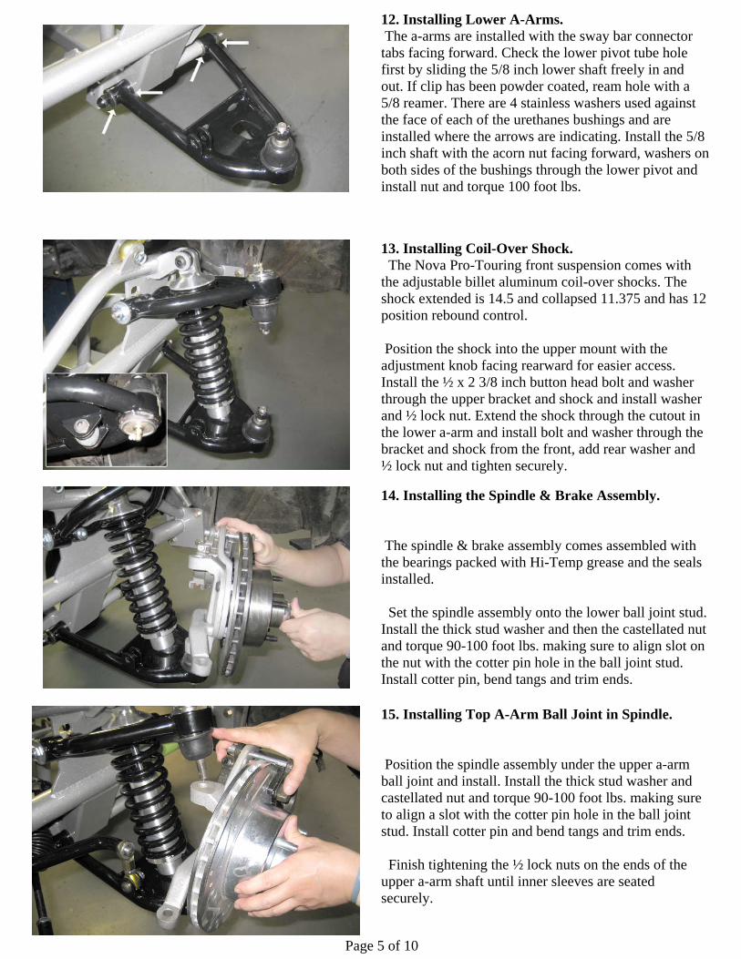
12. Installing Lower A-Arms. The a-arms are installed with the sway bar connector tabs facing forward. Check the lower pivot tube hole first by sliding the 5/8 inch lower shaft freely in and out. If clip has been powder coated, ream hole with a 5/8 reamer. There are 4 stainless washers used against the face of each of the urethanes bushings and are installed where the arrows are indicating. Install the 5/8 inch shaft with the acorn nut facing forward, washers on both sides of the bushings through the lower pivot and install nut and torque 100 foot lbs.
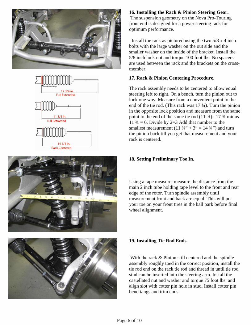
13. Installing Coil-Over Shock. The Nova Pro-Touring front suspension comes with the adjustable billet aluminum coil-over shocks. The shock extended is 14.5 and collapsed 11.375 and has 12 position rebound control. Position the shock into the upper mount with the adjustment knob facing rearward for easier access. Install the ½ x 2 3/8 inch button head bolt and washer through the upper bracket and shock and install washer and ½ lock nut. Extend the shock through the cutout in the lower a-arm and install bolt and washer through the bracket and shock from the front, add rear washer and ½ lock nut and tighten securely.
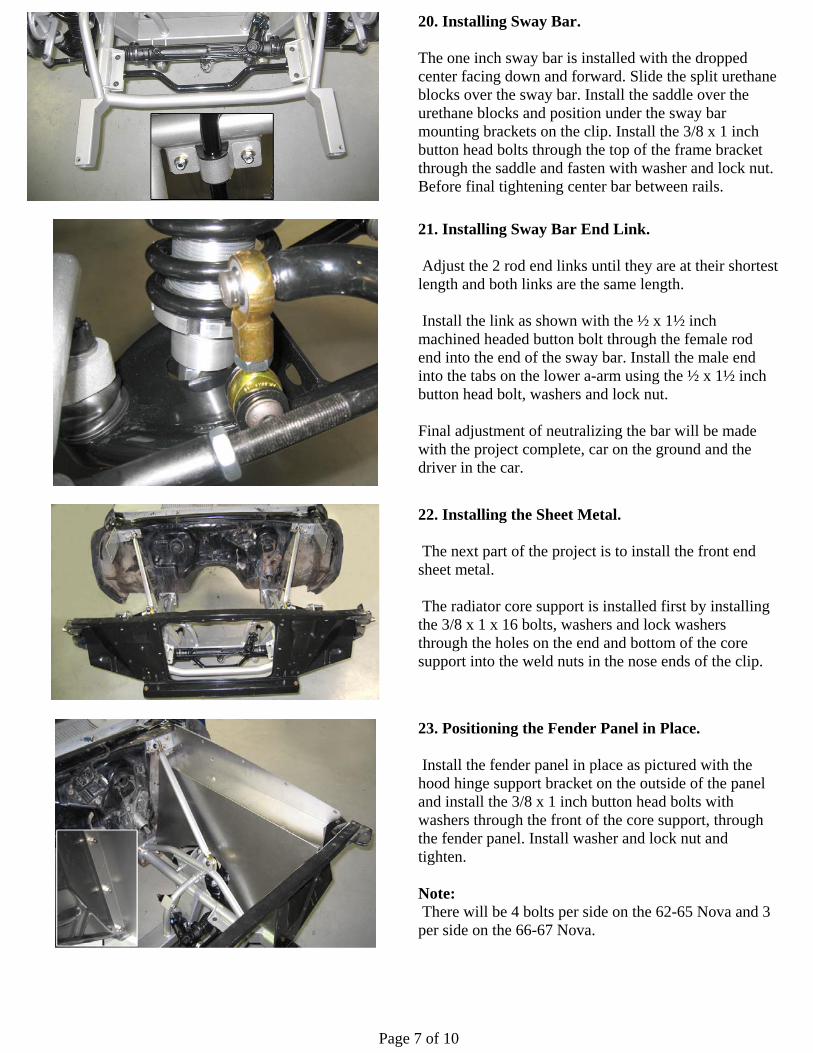
14. Installing the Spindle & Brake Assembly. The spindle & brake assembly comes assembled with the bearings packed with Hi-Temp grease and the seals installed. Set the spindle assembly onto the lower ball joint stud. Install the thick stud washer and then the castellated nut and torque 90-100 foot lbs. making sure to align slot on the nut with the cotter pin hole in the ball joint stud. Install cotter pin, bend tangs and trim ends.
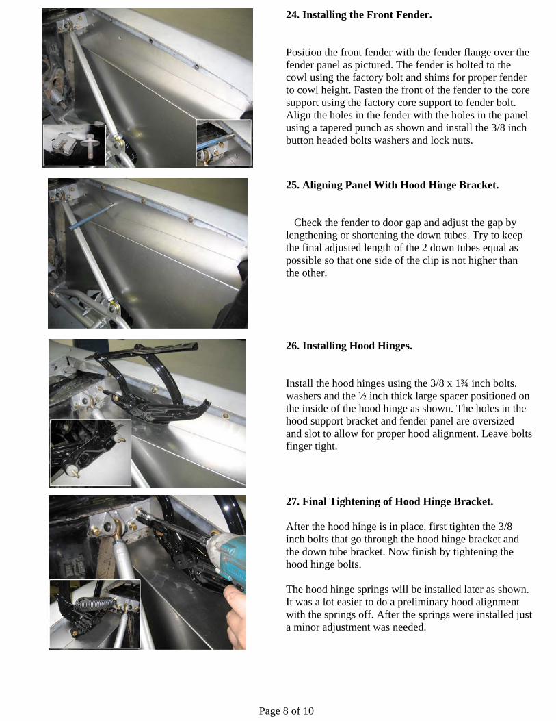
15. Installing Top A-Arm Ball Joint in Spindle. Position the spindle assembly under the upper a-arm ball joint and install. Install the thick stud washer and castellated nut and torque 90-100 foot lbs. making sure to align a slot with the cotter pin hole in the ball joint stud. Install cotter pin and bend tangs and trim ends. Finish tightening the ½ lock nuts on the ends of the upper a-arm shaft until inner sleeves are seated securely.
Page 6 of 10
16. Installing the Rack & Pinion Steering Gear. The suspension geometry on the Nova Pro-Touring front end is designed for a power steering rack for optimum performance. Install the rack as pictured using the two 5/8 x 4 inch bolts with the large washer on the out side and the smaller washer on the inside of the bracket. Install the 5/8 inch lock nut and torque 100 foot lbs. No spacers are used between the rack and the brackets on the cross-member.
17. Rack & Pinion Centering Procedure. The rack assembly needs to be centered to allow equal steering left to right. On a bench, turn the pinion out to lock one way. Measure from a convenient point to the end of the tie rod. (This rack was 17 ¾). Turn the pinion in the opposite lock position and measure from the same point to the end of the same tie rod (11 ¾). 17 ¾ minus 11 ¾ = 6. Divide by 2=3 Add that number to the smallest measurement (11 ¾” + 3” = 14 ¾”) and turn the pinion back till you get that measurement and your rack is centered.
18. Setting Preliminary Toe In. Using a tape measure, measure the distance from the main 2 inch tube holding tape level to the front and rear edge of the rotor. Turn spindle assembly until measurement front and back are equal. This will put your toe on your front tires in the ball park before final wheel alignment.
19. Installing Tie Rod Ends. With the rack & Pinion still centered and the spindle assembly roughly toed in the correct position, install the tie rod end on the rack tie rod and thread in until tie rod stud can be inserted into the steering arm. Install the castellated nut and washer and torque 75 foot lbs. and align slot with cotter pin hole in stud. Install cotter pin bend tangs and trim ends.
Page 7 of 10
20. Installing Sway Bar. The one inch sway bar is installed with the dropped center facing down and forward. Slide the split urethane blocks over the sway bar. Install the saddle over the urethane blocks and position under the sway bar mounting brackets on the clip. Install the 3/8 x 1 inch button head bolts through the top of the frame bracket through the saddle and fasten with washer and lock nut. Before final tightening center bar between rails.
21. Installing Sway Bar End Link. Adjust the 2 rod end links until they are at their shortest length and both links are the same length. Install the link as shown with the ½ x 1½ inch machined headed button bolt through the female rod end into the end of the sway bar. Install the male end into the tabs on the lower a-arm using the ½ x 1½ inch button head bolt, washers and lock nut. Final adjustment of neutralizing the bar will be made with the project complete, car on the ground and the driver in the car.
22. Installing the Sheet Metal. The next part of the project is to install the front end sheet metal. The radiator core support is installed first by installing the 3/8 x 1 x 16 bolts, washers and lock washers through the holes on the end and bottom of the core support into the weld nuts in the nose ends of the clip.
23. Positioning the Fender Panel in Place. Install the fender panel in place as pictured with the hood hinge support bracket on the outside of the panel and install the 3/8 x 1 inch button head bolts with washers through the front of the core support, through the fender panel. Install washer and lock nut and tighten. Note: There will be 4 bolts per side on the 62-65 Nova and 3 per side on the 66-67 Nova.
Page 8 of 10
24. Installing the Front Fender. Position the front fender with the fender flange over the fender panel as pictured. The fender is bolted to the cowl using the factory bolt and shims for proper fender to cowl height. Fasten the front of the fender to the core support using the factory core support to fender bolt. Align the holes in the fender with the holes in the panel using a tapered punch as shown and install the 3/8 inch button headed bolts washers and lock nuts.
25. Aligning Panel With Hood Hinge Bracket. Check the fender to door gap and adjust the gap by lengthening or shortening the down tubes. Try to keep the final adjusted length of the 2 down tubes equal as possible so that one side of the clip is not higher than the other.
26. Installing Hood Hinges. Install the hood hinges using the 3/8 x 1¾ inch bolts, washers and the ½ inch thick large spacer positioned on the inside of the hood hinge as shown. The holes in the hood support bracket and fender panel are oversized and slot to allow for proper hood alignment. Leave bolts finger tight.
27. Final Tightening of Hood Hinge Bracket. After the hood hinge is in place, first tighten the 3/8 inch bolts that go through the hood hinge bracket and the down tube bracket. Now finish by tightening the hood hinge bolts. The hood hinge springs will be installed later as shown. It was a lot easier to do a preliminary hood alignment with the springs off. After the springs were installed just a minor adjustment was needed.
Page 9 of 10
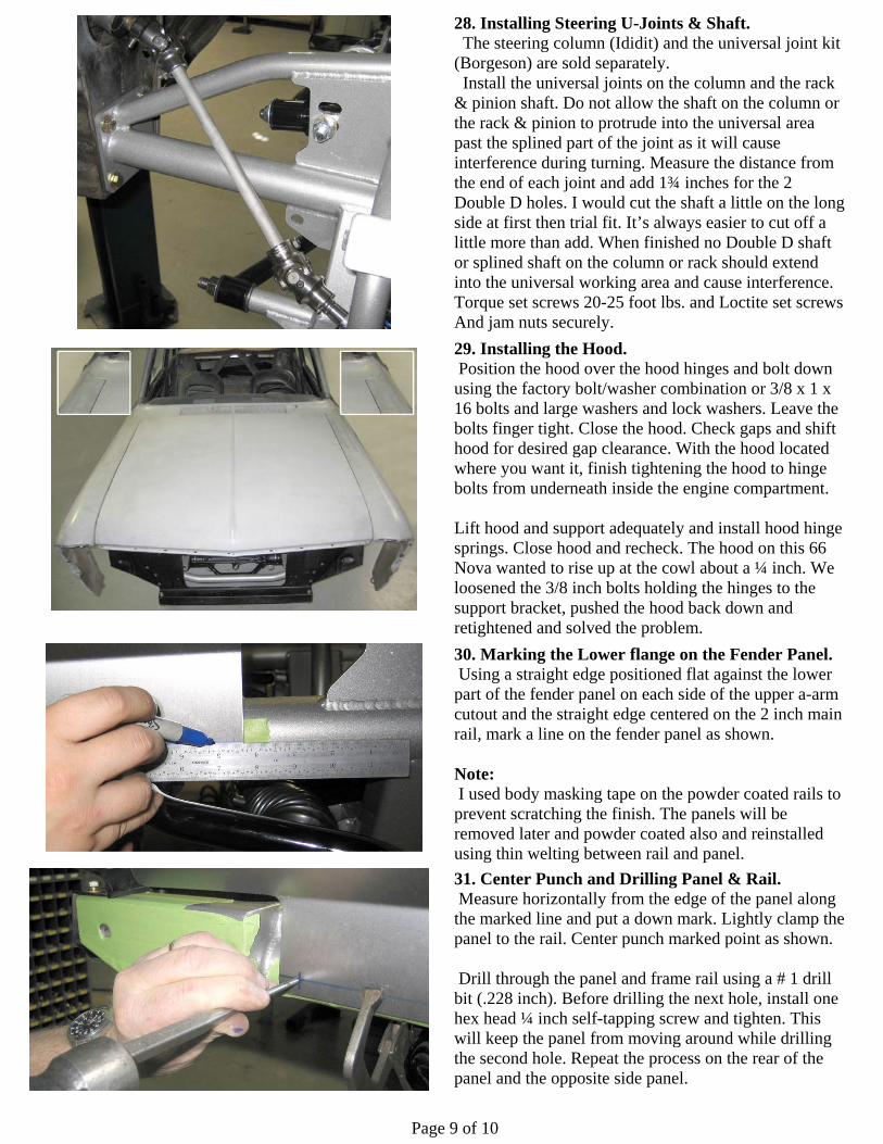
28. Installing Steering U-Joints & Shaft. The steering column (Ididit) and the universal joint kit (Borgeson) are sold separately. Install the universal joints on the column and the rack & pinion shaft. Do not allow the shaft on the column or the rack & pinion to protrude into the universal area past the splined part of the joint as it will cause interference during turning. Measure the distance from the end of each joint and add 1¾ inches for the 2 Double D holes. I would cut the shaft a little on the long side at first then trial fit. It’s always easier to cut off a little more than add. When finished no Double D shaft or splined shaft on the column or rack should extend into the universal working area and cause interference. Torque set screws 20-25 foot lbs. and Loctite set screws And jam nuts securely.
29. Installing the Hood. Position the hood over the hood hinges and bolt down using the factory bolt/washer combination or 3/8 x 1 x 16 bolts and large washers and lock washers. Leave the bolts finger tight. Close the hood. Check gaps and shift hood for desired gap clearance. With the hood located where you want it, finish tightening the hood to hinge bolts from underneath inside the engine compartment. Lift hood and support adequately and install hood hinge springs. Close hood and recheck. The hood on this 66 Nova wanted to rise up at the cowl about a ¼ inch. We loosened the 3/8 inch bolts holding the hinges to the support bracket, pushed the hood back down and retightened and solved the problem.
30. Marking the Lower flange on the Fender Panel. Using a straight edge positioned flat against the lower part of the fender panel on each side of the upper a-arm cutout and the straight edge centered on the 2 inch main rail, mark a line on the fender panel as shown. Note: I used body masking tape on the powder coated rails to prevent scratching the finish. The panels will be removed later and powder coated also and reinstalled using thin welting between rail and panel.
31. Center Punch and Drilling Panel & Rail. Measure horizontally from the edge of the panel along the marked line and put a down mark. Lightly clamp the panel to the rail. Center punch marked point as shown. Drill through the panel and frame rail using a # 1 drill bit (.228 inch). Before drilling the next hole, install one hex head ¼ inch self-tapping screw and tighten. This will keep the panel from moving around while drilling the second hole. Repeat the process on the rear of the panel and the opposite side panel.
Page 10 of 10
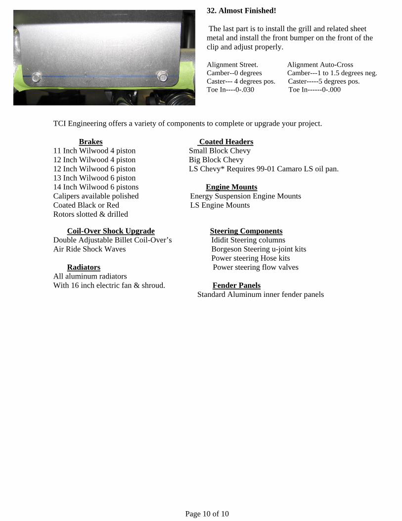
32. Almost Finished! The last part is to install the grill and related sheet metal and install the front bumper on the front of the clip and adjust properly. Alignment Street. Alignment Auto-Cross Camber--0 degrees Camber---1 to 1.5 degrees neg. Caster--- 4 degrees pos. Caster-----5 degrees pos. Toe In----0-.030 Toe In------0-.000
TCI Engineering offers a variety of components to complete or upgrade your project. Brakes Coated Headers 11 Inch Wilwood 4 piston Small Block Chevy 12 Inch Wilwood 4 piston Big Block Chevy 12 Inch Wilwood 6 piston LS Chevy* Requires 99-01 Camaro LS oil pan. 13 Inch Wilwood 6 piston 14 Inch Wilwood 6 pistons Engine Mounts Calipers available polished Energy Suspension Engine Mounts Coated Black or Red LS Engine Mounts Rotors slotted & drilled
Coil-Over Shock Upgrade Steering Components Double Adjustable Billet Coil-Over’s Ididit Steering columns Air Ride Shock Waves Borgeson Steering u-joint kits
Power steering Hose kits Radiators Power steering flow valves All aluminum radiators With 16 inch electric fan & shroud. Fender Panels Standard Aluminum inner fender panels