1971 -1975 - william j. hughes technical center · 2012-08-07 · 1971 - 1975 technical ~eport...
TRANSCRIPT

]
I
Report No. FAA·RD-76-74 l.- IV fl - 7j-- t: f
COPY~
AN ANNOTATED COMPILATION OF NAFEC
VISUAL AID LETTER AND DATA REPORTS
1971 - 1975
E. Leon Reamer
MAY 1976
FINAL REPORT
JWIIIc lii~.ARY
M2 78
Document is available to the public through the National T echo ical Information Service
Springfield, Virginia 22151
·~.~ ..
Prepared for
U. S. DEPARTMENT OF TRANSPORTATION FEDERAL AVIATION ADMINISTRATION Syste11s Research & Dnelop11ent Service
Washington, D.C. 20590
NOTICE
This document is dis seminated under the sponsorship of the Department of Transportation in the interest of information exchange. The United States Government assumes no liability for its contents or use thereof.
I,

1. Report No. 2. Government Accession No.
FAA-RD-76-74 4. Title and Subtitle
AN ANNOTATED COMPILATION OF NAFEC VISUAL AID LETTER AND DATA REPORTS
1971 - 1975
Technical ~eport Documentation Page
3. Recipient's Cotalog No.
5. Report Date
May 1976 6. Performing Organization Code
1-:;~~:--;-:-----------------------------! 8. Performing Organization Report No. 7. Authorl s)
E. Leon Reamer 9. Performing Organization Name and Address
Federal Aviation Administration National Aviation Facilities Experimental Center Atlantic City, New Jersey 08405
FAA-NA-75-69 10. Work Unit No. (TRAIS)
11. Contract or Grant No.
071-312-040 13. Type of Report and Period Covered
~1~2-. -S-po_n_s-or-in_g_A_g_e_n-cy-N-am-e-an_d_A_d_d~re_s_s __________________________ ~ Final
U.S. Department of Transportation November 1971 - April 1975 Federal Aviation Administration Systems Research and Development Service Washington, D.C. 20590
15. Supplementary Notes
16. Abstract
14. Sponsoring Agency Code
This report releases Federal Aviation Administration (FAA) letter and data reports to the general public. These reports were issued by the National Aviation Facilities Experimental Center (NAFEC) to the System Research and Development Service (SRDS) between the years 1971 to 1975, and cover testing and evaluation efforts for visual guidance and airport lighting configurations.
Contained herein are the original letter and data reports including an annotation of the results and actions brought about by their findings.
17. Key Words
Visual Aids Airport Lighting VAS! Inset Runway Lighting Displaced Threshold 19. Security Classif. (of this repart)
Unclassified
Form DOT F 1700.7 !8-72)
18. Distribution Statement Document is available to the public through the National Technical Information Service Springfield, Virginia 22151
20. Security Classif. (of this page) Unclassified
Reproduction of completed page authorized
21· No. of Pages 22. Price
69

INTRODUCTION
Purpose Background
DISCUSSION
General VASI Syst'ems
>" >
TABLE OF CONTENTS
Semiflush Airport Lights Approach Light System Lamps STOLport Beacon Displaced Threshold Lighting Constant Current Regulators Radio Remote Control of Airport Lighting System Aiming Point Lights Cockpit Fog Simulator Taxiway Guidance Signs Runway Alignment Identifies Light System (RAILS) Nonprecision Approach Runway Lights Category III Lighting System
APPENDIXES
A - Reducing Lateral Coverage of Standard VASI Unit, Data Report, November 1971
B - Surface Temperature of Several Types of In-Pavement
Page
1
1 1
1
1 1 2 2 3 3 3 4 4 4 5 5 5 5
Lighting Fixtures, Data Report, March 1972 and September 1974
C - Temperatures of PAR-56 Lamps Used in the Approach Light System, Data Report, May 1972
D - Evaluation of Beacon for use to Identify a STOLport, Data Report, March 1973
E - Displaced Threshold Lighting, Letter Report, November 1973
F - Request of Load Data Constant Current Regulators, Activity 06 Quick Reaction to Solve Field-Encountered Problems, Data Report, January 1974
G - Quick Reaction--Radio Remote Control, Letter Report, August 1974
H - Aiming Point Lights, Letter Report, September 1974
iii

TABLE OF CONTENTS (Continued)
I - Cockpit Fog Simulator, Letter Report, November 1974
J - Taxiway Guidance Signs, Letter Report, November 1974
K - Quick Reaction to Field-Encountered Problems (Evaluation of Omnidirectional Strobe Lights), Letter Report, December 1974
L - Nonprecision Approach Runway Lights, Letter Report, February 1975 and April 1975
M - Category III Lighting System, Letter Report, April 1975
iv

Figure
A-1
A-2
A-3
A-4
B-1
B-2
B-3
B-4
B-5
E-1
J-1
M-1
M-2
LIST OF APPENDIXES ILLUSTRATIONS
VAS! With Internal Baffles, Setup No. 1
VAS! With Internal Baffles, Setup No. 2
VAS! With Internal Baffles, Setup No. 3
VAS! With Internal Baffles, Setup No. 4
Temperature Vs. Time, Fixtures MC-2 and Mc-2A
Temperature Vs. Time, Fixture L-850A
Temperature Vs. Time, Fixture L-850B
Temperature Vs. Time, Fixture L-852
Temperature Vs. Time, Fixture FAA-E-2491
Displaced Threshold Test Bed
Map of NAFEC Airport with Location of Signs and Range Marks
Centerline Inset Light Visibility as Percentage of Edge Light Visibility
Touchdown Zone Light Visibility as Percentage of Edge Light Visibility
v
Page
A-2
A-3
A-4
A-6
B-4
B-5
B-6
B-7
B-8
E-3
J-1
M-3
M-4

INTRODUCTION
PURPOSE.
The purpose of this report is to annotate and release Federal Aviation Administration (FAA) letter and data reports. These reports were issued by the National Aviation Facilities Experimental Center (NAFEC) to the Systems Research and Development Service (SRDS) between the years 1971 to 1975 and cover testing and evaluation efforts for visual guidance and airport lighting systems.
BACKGROUND.
During the course of an activity involving NAFEC and SRDS, letter and data reports were generated at NAFEC. These reports invariably sought answers to specific questions assigned to NAFEC by SRDS. The primary intent of these reports was to quickly distribute essential technical information on specific investigations, analyses, or tests to a limited audience. After a close inspection of the contents of the 15 NAFEC reports, it seemed logical that many of them would be of interest to the general-aviation community and should be made available as a single formal report.
The data reports provided information that resulted from specific SRDS-requested tests. Conclusion or recommendations are not included in this type of report. The letter reports, also presented in this document, are similar to formal FAA reports but do not normally contain data to substantiate the conclusion and recommendations. Data collected for letter reports remain on file for a limited time period and are available at NAFEC upon request.
DISCUSSION
GENERAL.
The reports presented herein are in chronological order. Each report presented in the appendices has an edited introduction in this section so that the reader may ascertain the specific topic of the report and other pertinent information that would not be found in the original report.
VAS! SYSTEMS.
DESCRIPTION. The visual approach slope indicator (VAS!) is designed to furnish the pilot with visual information for safe descent guidance. The system is primarily intended for use during visual flight rules (VFR) weather conditions.
The VAS! provides a definite white and red light projection along the desired descent path to touchdown point. The light units are arranged in upwind and
1

downwind bars. The light units in each bar are located on a line perpendicular to the runway centerline. The downwind bar is the nearest to the runway threshold and the upwind bar is the farthest.
Each light unit projects a split beam of light, the upper segment being white and the lower red. The transition from red to white, or vice versa, occurs over a vertical angle of approximately one-quarter degree with the light in this area being pinkish in color. The system produces a well-defined corridor of light consisting of red and white beams. When on the proper glide path the downwind bar appears white and the upwind red. If the approach is too high, both bars are seen as white while a low approach is indicated by both bars appearing red.
EVALUATION. This data report in appendix A prepared by C. B. Phillips, dated November 1971, proposes means for decreasing the lateral coverage of a standard VASI unit to near 12°.
RESULT AND ACTION. This report made possible VASI installations where dangerous conditions would exist from obstructions, if standard VASI with normal horizontal coverage were used.
SEMIFLUSH AIRPORT LIGHTS.
DESCRIPTION. Where it is normal or possible for an aircraft to travel on the ground surface over a light source, the light source is mounted on a steel can and installed in a position so that an aircraft may readily run over it. The limiting factor for height of the fixture is that height which the aircraft may cross over with little inputs to the plane's maneuvering. These light sources are found in displaced thresholds, thresholds, centerlines (both taxiway and runway), and touchdown zone areas.
EVALUATION. Two data C. B. Phillips, dated dated September 1974. lights.
reports are in appendix B. One was prepared by March 1972, and the second was prepared by R. E. Johnston,
The reports define heat generated by semiflush airport
RESULT AND ACTION. The U.S. Advisory Group to the Visual Aids Panel of the International Civil Aviation Organization (ICAO) supports as a standard in document Annex 14 International Standards and Recommended Practices-Aerodromes. The maximum heat that may be tolerated from inset lights to an aircraft tire.
APPROACH LIGHT SYSTEM LAMPS.
DESCRIPTION. The standard high-intensity approach lighting system (ALS) uses PAR-56 incandescent aviation service lamps. These are sea~ed beam lamps with a parabolic reflector as part of the lamp. In certain areas of the approach lighting system, filters are used with the lamps. These filters may be either green or red.
2

EVALUATION. May 1972. lamps.
This data report appendix C,prepared by C. B. Phillips, dated It defines the heat generated by 500-watt PAR-56 aviation service
RESULT AND ACTION. This report supported the specifications that green threshold light filters be installed 2 inches from the light fixture lamp. This reduced the amount of green filters damaged by heat transfer from the lamp.
STOLPORT BEACON.
DESCRIPTION. STOLport beacons must indicate that the airport is only suitable for short takeoff and landing (STOL) operations. The beacon must serve the purpose of attracting the pilots of STOLcraft to the airport.
EVALUATION. This data report in appendix D, was prepared by E. Leon Reamer, dated March 1973, and evaluates several beacon light configurations proposed for use at an airport where STOLcraft operation ONLY is used,
RESULT AND ACTION. No action was taken as a result of this report.
DISPLACED THRESHOLD LIGHTING.
DESCRIPTION. Threshold lighting indicates to landing pilots that the threshold of the runway for landing operations has been moved down the runway from the physical start of the runway. This may be caused by construction on the runway, obstructions in the glide path area or anything that makes landing on the runway near the physical threshold area unsafe.
EVALUATION. This letter report in appendix E, prepared by E. Leon Reamer, dated November 1973, evaluated means by which medium-intensity lighting, in conjunction with runway end identifiers (REILS), may be used as a temporary displaced threshold lighting system.
RESULT AND ACTION. No action was taken as a result of this report.
CONSTANT CURRENT REGULATORS.
DESCRIPTION. The term constant current regulator as defined in airport lighting is a device for regulating the electrical current energizing a series circuit that operates visual aids. It differs from standard power systems as the voltage varies with load consumption rather than the current output. Low power systems would have a comparative low voltage while high power systems would have a comparatively higher voltage.
EVALUATION. This data report in appendix F, prepared by E. Leqn Reamer, dated January 1974, established input and output parameters for airport type regulators. The input data was specifically requested for determining electrical power savings that could be realized by operating the regulators on a lower power setting.
3

RESULT AND ACTION. This report assisted in establishing a specification for a radio control of airport lighting.
RADIO REMOTE CONTROL OF AIRPORT LIGHTING SYSTEM.
DESCRIPTION. The system must have the capability of turning on airport lighting at emergency airports or at airports where there are no attendants during an entire 24-hour period. The system would need to be operated through the aircraft very high frequency (VHF) transmitter.
EVALUATION. This letter report in appendix G, prepared by Thomas H. Paprocki, dated August 1974, proposes use of a t.one burst selective air-to-ground radio remote control system for airport lighting.
RESULT AND ACTION. This report assisted in establishing a specification for a radio remote control of airport lighting.
AIMING POINT LIGHTS.
DESCRIPTION. This was a system of semiflush lighting installed in the touchdown zone area of a Category I or Category II runway to assist the pilot in determining the point of touchdown for his aircraft. Basically, the lights would illuminate the area of the "fix distance markers" on the runway.
EVALUATION. This letter report in appendix H, prepared by Thomas H. Paprocki, dated September 1974, proposed a method for illuminating an area in which a pilot might touchdown his aircraft on the runway in low visibility conditions. It was accomplished by using different configurations of colored semiflush lighting on the runway.
RESULT AND ACTION. No action was taken as a reslult of this report.
COCKPIT FOG SIMULATOR.
DESCRIPTION. This simulator was installed in a four-engine jet aircraft and was used by the pilot in the left seat to view the landing visual aids. The simulator was designed for daytime operation and was to be used as a 'test bed' to simulate all-weather conditions when such conditions did not exist for evaluating lighting and marking aids.
EVALUATION. This letter report in appendix I, prepared by Thomas H. Paprocki, dated November 1974, evaluated the daylight cockpit fog simulator for use as a test bed in testing all-weather lighting and marking systems.
RESULT AND ACTION. This report determined the validity of a daylight cockpit fog simulator. The device is used to simulate various daylight all-weather landing conditions, therefore, reducing the requirements-to test all systems with maximum pilot observers during real-weather conditions.
4

TAXIWAY GUIDANCE SIGNS.
DESCRIPTION. These are signs that indicate to pilots taxiing on the airport what conditions may exist or information as to runway and taxiway intersections.
EVALUATION. This letter report in appendix J, prepared by Thomas H. Paprocki, dated November 1974, evaluated several manufacturers' taxiway guidance sign configurations during night conditions.
RESULT AND ACTION. This report assisted in establishing a new type of taxiway guidance sign: FAA Specification L-858, Retroreflective Taxiway Guidance Sign.
RUNWAY ALIGNMENT IDENTIFIER LIGHT SYSTEM (RAILS).
DESCRIPTION. This is a system of condenser-discharge lights leading into a runway threshold. Normally, theyprecede an incandescent medium intensity lighting system. RAILS are basically used to identify a runway and align the pilot with the runway for an accurate approach and landing.
EVALUATION. This letter report in appendix K, prepared by Thomas H. Paprocki, dated December 1974, evaluated a system of omnidirectional, condenser-discharge lights to be used as a runway alignment indicator system in place of the presently approved directional condenser-discharge lights. NOTE: Strobe lights are condenser-discharge lights.
RESULT AND ACTION. An order is being issued approving the use into Category I conditions of omnidirectional, condenser discharge lights.
NONPRECISION APPROACH RUNWAY.
DESCRIPTION. This is a runway that is not served by a glide slope antenna or a precision approach radar. It may be served by other electronic means such as a very high frequency omnirange (VOR).
EVALUATION. These two letter reports in appendix L, prepared by Guy S. Brown, dated February and April 1975 reported upon an evaluation to determine the adequacy for providing guidance to a pilot using nonprecision runway lights employing omnidirectional lenses and inexpensive vehicular type traffic lamps.
RESULT AND ACTION. An Advisory Circular has been issued authorizing the use of omnidirectional runway edge lights, for nonprecision runways.
CATEGORY III LIGHTING SYSTEM.
DESCRIPTION. Presently there is no United States approved ligqting system for Category III weather condition landings other than the Category II lighting. This lighting has been investigated many times to determine if individual components of the total system were in balance.
5

EVALUATION. This letter report in appendix M, prepared by Raymond E. Johnston, dated April 1975, indicated the compatibility of the runway edge, centerline and touchdown zone lights in Category II and Category III weather conditions.
RESULT AND ACTION. From this report, and other sources, it was determined that the present system of high-intensity runway lights is well balanced for Category III operations.
6

APPENDIX A
REDUCING LATERAL COVERAGE OF STANDARD VASI UNIT NOVEMBER 1971
INTRODUCTION
PURPOSE.
The purpose of this phase of the project was to obtain an optimum means for decreasing the lateral coverage of a standard visual approach slope indicator (VASI) unit, the minimum coverage to a sharp cutoff to be near 12°.
BACKGROUND.
In some approach areas, there are obstructions that prevent the use of the entire VASI lateral coverage area for aircraft to approach the threshold of the runway. If conventional VASI units were used in these conditions, oncourse information could be given to the pilot that could cause the aircraft to strike obstructions. Some changes are needed to decrease the lateral coverage of the VASI units that are to be used in these type of approach areas.
DISCUSSION
The conventional VASI unit has a lateral coverage of 27° to 50 percent of the maximum intensity (22,000 candelas), a coverage of 60° to an intensity of 100 candelas, and a coverage of about 80° to an intensity of zero candelas. A sharp cutoff would be necessary for this application as an intensity of 100 candelas could be seen a considerable distance under visual flight rule (VFR) night conditions.
Different types of baffles were designed and installed in a standard VASI unit and photometric measurements were made to determine the lateral coverage for a sharp cutoff to an intensity of zero candelas.
RESULTS
The location for the first set of baffles and louvers is shown in a horizontal cross sectional view in figure A-1. The resulting lateral angle, to 100 candelas, was 33°. Photometric data was not taken to zero candelas.
Another baffle was added as shown in figure A-2. This resulted in an increase of the angle to 37°. With all baffles and louvers painted black, there was a reflection from the side louvers as shown by the dotted lines in figure 2, and this caused the increase in the lateral angle.
This next attempt was to remove the front 12-inch louvers, and the two 22-inch louvers, and add four more baffles as shown in figure A-3. This resulted in lateral beam, to zero candelas, of about 20°.
A-1

1 l 0 II
12" •It 8"
t ·II 6"
t 30" 14
I I I 8"
:r N t
6"
I
T I
6"
t j_
8"
I I I
t I I
l 0 II
~ 75-69-A-1
FIGURE A-1. VASI WITH INTERNAL BAFFLES, SETUP NO. 1

:r w
'-
t 10"
L._ __ ... ,l UMP ~ I VF!LTER --- 8"
: --1-.:>n ~ t6
" ---~ .. 6" .30" j_ L-
r-
8"
----t ~22" ·I· _ -f
I I I . -·-
!--+-_----~ I - --- -----=f
10"
~ 75-69-A-2
FIGURE A-2. VASI WITH INTERNAL BAFFLES, SETUP No. 2

:r .j::-
------11 10"
LAMP
VTER I I
T 6"
j_
T 6"
j_ lZ" 1-+---12"
1 {'"
6"
-t 7 1/2 11
-t 6"
.. 1 .. 10"--d-7 1 /2"
t _____ _j] 75-69-A-3
FIGURE A-3. VASI WITH INTERNAL BAFFLES, SETUP No. 3

>. V1
-----11. LAMP
/ VLTER I I
, __ r-
-t 7 3/411
w •I.. 15" •I; 14" •1-t 6 11 6 11
j_ -t 7 3/411
T -t 6" 6"
~ -t 7 3/411
t -----_jJ
75-69-A-4
FIGURE A-4. VASI WITH INTERNAL BAFFLES, SETUP No. 4

The VASI unit that was used for these development tests was one of the older units. It was thought that the same system of baffles would be satisfactory in the VASI units now in use. The same system of baffles was installed in one of these VASI units. The exception was a change in the spacing and this is shown in figure A-4. The internal baffles were secured to the cross members of the VASI unit. This unit was installed for flight testing on the lett side of runway 13 at NAFEC.
Flights were made in daylight at right angles to the VASI unit to determine the observed lateral angle. The flights were made at distances of 15,200 and 12,800 feet from the units. Angles were determined for both the standard unit and the redesigned unit for both distances. A total of 12 passes were made.
The average observed lateral angles are given in table A-1.
TABLE A-1. AVERAGE LATERAL ANGLE CALCULATED FROM THE FLIGHT TESTS
VASI Standard Baffled
Distance
12,800 26.5° 12.5°
The angle was measured in the photometric laboratory and was found to be 16°. The difference in the observed angle and the measured angle is due to the lower intensities not being seen in flight thus resulting in a smaller effective angle.
Photometric data were taken with the left front 10-inch baffle removed. The angle on the left side was 17° and on the right 9°. This shows that if obstructions are only on one side of the approach area then approximate full coverage for the other side could be obtained by removing the corresponding front baffle.
The use of this system of baffles resulted in a decrease in the oncourse intensity of approximately 5 percent.
A-6

APPENDIX B
SURFACE TEMPERATURE OF SEVERAL TYPES OF IN-PAVEMENT LIGHTING FIXTURES MARCH 1972 AND SEPTEMBER 1974

INTRODUCTION
PURPOSE.
The purpose of this phase of the project was to determine the surface temperature of several in-pavement lighting fixtures used in airport lighting.
BACKGROUND.
The power used in airport in-pavement lighting fixtures has steadily increased from a beginning of 10 to 750 watts at the present time.
A recent advisory to United Kingdom pilots warning them of possible damage to aircraft tires from high temperatures of in-pavement lights has raised the same question in regard to lights used in the United States.
Therefore, it was necessary to obtain the top surface temperature of the inpavement lighting fixtures used in airport lighting in the United States.
DISCUSSION
Each type of in-pavement lighting fixture now being used in airport lighting was operated in a simulated installation condition. The fixture was installed in an 18 by 18 by 21-container filled with sand. The fixture was operated at step 5(100 percent brightness); the location, on the top of the fixture, of the maximum temperature, was determined and temperature data were obtained. The temperatures were obtained with a Minimite Portable Pyrometer using an iron-constantan thermocouple. This instrumentation was manufactured by the Thermo Electric Company, Inc., of Saddle Brook, N.J. The fixture was operated in still air and temperatures were obtained until a partial leveling off was obtained.
An aircraft tire from a DC3 was then placed on the operating fixture. The aircraft tire used was a B. F. Goodrich Silvertown designated as type III, 10 ply rating nylon, 17:00 x 16, TSO-C 62 B. The corners of a three-quarter inch plywood board, 14 inches wide by 20 inches long, were rounded to fit inside the tire. Five bags (125 pounds) of shot were piled onto the board to cause the tire to conform to the curvature of the lighting fixture.
Temperatures were continually taken at timed intervals for at least an hour. These temperatures did not seem to level off but continued to increase slowly.
B-1

RESULTS
The rating of the lamps, ambient temperature, operating time of lamp, temperature of fixture top, operating time of lamp with tire on fixture, temperature of fixture under tire and number of figure in which these data are shown, are given in table B-1:
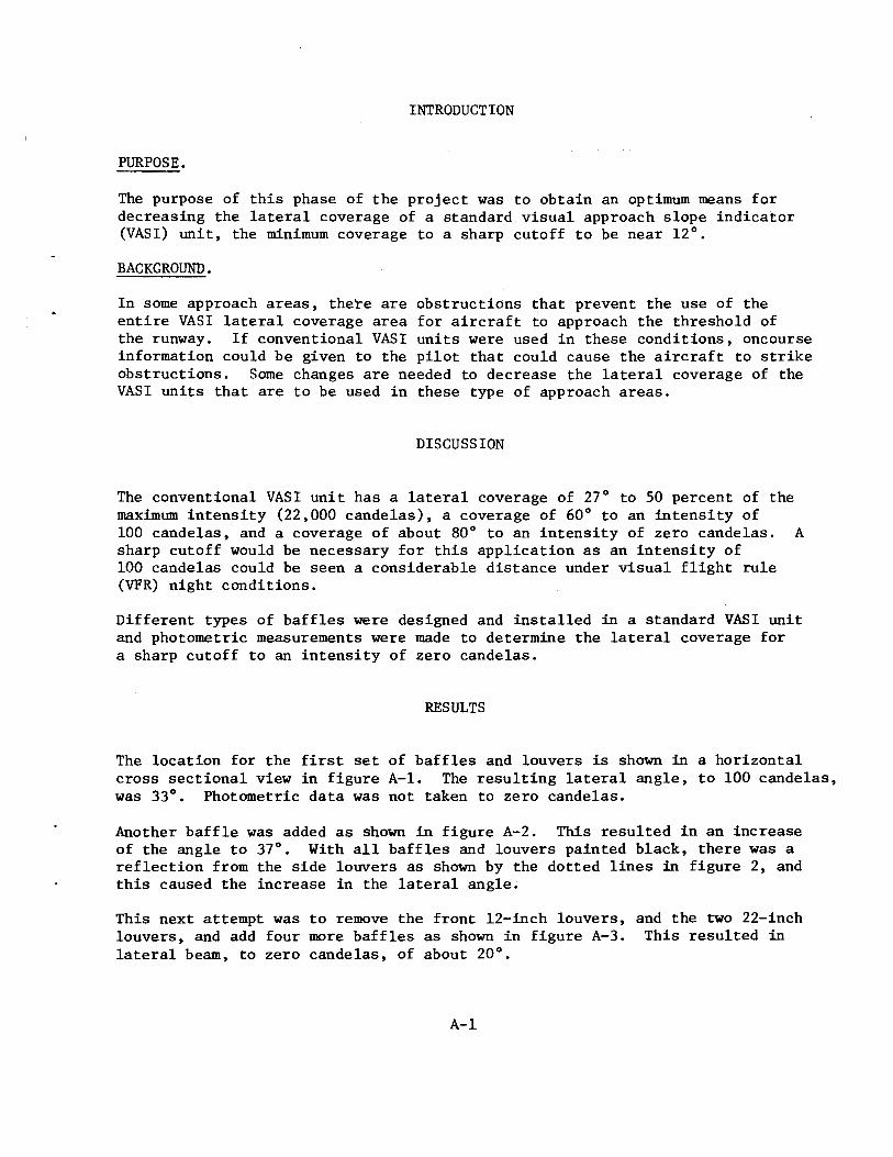
Figures B-1 to B-5 show the temperature rise vs. time for in-pavement lighting fixtures used in aircraft lighting. It is noted from these figures that the temperatures of the fixture top do not level off but continue to rise at a different rate for the different fixture.
The data given are for a longer period of time than an aircraft would normally be expected to park on a lighted in-pavement lighting fixture.
Different portions of the tire tread were utilized for these tests. In instances, when the tire remained on the lighted fixture for a longer time than normal, the temperature increased until the exposed surface of the rubber slightly softened. This did not seem to have seriously damaged the tire: however, it is possible that this could cause the tire to wear faster in spinups on landing. During these tests there was no indication of the tire smoking as is prevalent in actual spinups on landing.
Whether or not these temperatures would be damaging to aircraft tires being used would depend upon the type of rubber used in the tire and the length of time the tire would be in contact with the lighted fixture.
B-2

TABLE B-1. DETAILED UNDER TIRE IN-PAVEMENT LIGHTING FIXTURE TEMPERATURE DATA
Ambient Lamp Rating Temperature Fixture Top Tire On Fixture Figure Fixt~ Tem:2erature Am:2eres Watts Time {Min} Tem:2erature Time {Min} Tem:2erature Number
FM-1199 68 20.0 500 115 235 75 345 1 MC-2 L-845 70 6.6 200 MC-2A
90 166 55 228 1
L-850A 70 6.6 200 225 284 80 347 2 L-850B 72 6.6 200 190 272 85 345 3 L-852 70 6.6 60 331 274 380 385 4
b:l FM-E-2491 70 20.0 500 330 263 110 379 5 I c.,.) FM-E-2491 70 20.0 750 380 308 60 440 5
TIRE ON LIGHTING FIXTURE AT START OF TEST
L-850A 70 6.6 200 - - 180 339 2 L-850B 68 6.6 200 - - 283 395 L-850B 70 6.6 200 - - 170 348 3
NOTE: TEMPERATURES IN DEGREES FAHRENHEIT

t:d I
.s:-
350-------------------------------;--------------~
300
-~
U)
t.l fil ~ 250 s 0 ._.
t.l ~ p f:-i
~ 200 t.l P-4 ~ t.l f:-i
150
MC-2 FIXTURE
CD TIRE ON FIXTURE
+- TEMPERATURE OF FIXTURE AFTER 115 MINUTES
MC-2A FIXTURE
@TIME ON FIXTURE
+- TEMPERATURE OF FIXTURE AFTER 90 MINUTES
roo~------------~------------._------------L-------------L----0 1 2 3 4 5
TIME ( HOURS ) 75-69-B-1
FIGURE B-1. TEMPERATURE Vs. TIME, FIXTURES MC-2 AND MC-2A

350~--------------------------------------------------------------------~
300
~
U)
la:l .. la:l c:r: 250 I) la:l 0 I f ./ L-850A FIXTURE
~zoo~ 1/ CD FIXTURE TEMPERATURE
txl +- TIRE ON FIXTURE
I V1 0 TIRE ON FIXTURE AT
la:l BEGINNING OF TEST
0-t ~ la:l E-t
150
lOOL-------------~------------L-------------~------------~------------~ 0 1 2 3 4 5 TIME ( HOURS ) 75-69-B-2
FIGURE B-2. TEMPERATURE Vs. TIME, FIXTURE L-850A
350--------------------------~--------------~~--~
300
-~
~ Col ~ 250
~ Cl I f / L-850B FIXTURE
~ 200~ v CD FIXTURE TEMPERATURE
- TIRE ON FIXTURE
t:,;l ® TIRE ON FIXTURE AT I BEGINNING OF TEST 0\ Col
ll4 ~ Col ~
150
100~------------------------~------------------------~------------------------~----------------~------------------~ 0 1 2 3 4 5
TIME ( HOURS ) 75-69-:8-3
FIGURE B-3. TEMPERATURE Vs. TIME, FIXTURE L-850B

c:l I
-..J
400~------------------~----------------------------------------------,
350
-~
til ril ~ ~ 300 0 ~ 0 -~ ~ p E-t ~ 250
ril 114 ~ ~ E-t
200
TIRE PLACED ON FIXTURE 4 HRS. AND 25 MIN. AFTER REACHING TEMPERATURE OF APPROXIMATELY 274°
<D
L-852 FIXTURE
CD FIXTURE TEMPERATURE
® TIRE ON FIXTURE
15n~------------~------------~------------~------------~~------------L-------------~ 0 1 2 3 4 5 6 TIME ( HOURS ) 75-69-B-4
FIGURE B-4. TEMPERATURE Vs. TIME, FIXTURE L-852

b::l I
():)
450------------------------.
~
~ til 350 ~
~ Q
~ E-t ~ 300
til ~ ~ [.zl E-t
250
2000
-
FAA- E- 2491
750-W FIXTURE
+- TEMPERATURE OF FIXTURE AFTER 380 MINUTES
CD TIRE ON FIXTURE
1 TIME IN HOURS
2
450----------------------~
400
~
tf.l til til ~ 350 a til Q -til ~ lJ E-t < 300 ~ til ~ ~ til E-t
250
·-FAA - E- 2491
500-W FIXTURE
+- TEMPERATURE OF FIXTURE AFTER 330 MINUTES
CD TIRE ON FIXTURE
200~------------~--------~--~ 0 1 2
TIME IN HOURS
75-69-B-5
FIGURE B-5. TEMPERATURE Vs. TIME, FIXTURE FAA-E-2491

INTRODUCTION
PURPOSE.
The purpose of this effort was to determine the surface temperatures of several types of in-pavement lighting fixtures used on runways and taxiways.
BACKGROUND.
This effort resulted from a letter dated August 5, 1974, from AAS-500 to ARD-300, requesting t~sts to verify whether the in-pavement lights used by the United States, meet the proposed ICAO Standards:
That the surface temperature shall not exceed 302° F when contact between a tire and the light has been maintained for 10 minutes.
DISCUSSION
The fixtures were installed in a concrete test strip simulating a section of a runway.
The lights were operated at full intensity for 2 hours prior to the heat measurements.
The initial surface temperatures were recorded.
A 9-ton tank truck was employed using the front wheel to make contact with each fixture.
The temperature readings were recorded after a lO~inute period for each fixture.
The fixture types, rated wattage, initial and final temperature recordings, are given in table below:
Lamp Initial Final Fixture Rating Temperature Temperature
Type (Watts) (oF) (oF)
L838 II 300 158 156 L845 II 200 155 148 L842 45 200 210 L843 200 234 254 L850 A 200 211 205 L850 B 200 284 306 L852 65 258 272 L838 II 500 195 241 FAA-E-2491 750 220 300
B-9

APPENDIX C
TEMPERATURES OF PAR-56 LAMPS USED IN THE APPROACH LIGHT SYSTEM MAY 1972

INTRODUCTION
PURPOSE.
The purpose of this phase of the project was to determine the maximum operating temperatures of PAR-56 lamps that are used in the approach light system.
BACKGROUND.
Reports from the regions indicate considerable breakage of lamps and color filters. These seem to occur during rain storms or snow showers. It was requested that the operating temperature of these lamps, in combination with different color filters and filter holders of varying .lengths, be determined.
DISCUSSION
The drawings for the PAR-56 lamp holders indicate that the filter holders should be attached to the back of the rim. An investigation of some installations of PAR-56 lamp holders revealed that about half of the filter holders were attached to the front of the rim. The front attachment increases the spacing between the lamps and filters. One inquiry was made and it was discovered that lamps were breaking regardless of whether the filter holders were in front or back of the rim. It was requested that the resulting temperatures be investigated when the space between the lamps and the filters was increased. Longer filter holders, together with spacers, were used to increase the space between the lamp and the color filter.
The lamps used for these tests were 500 watt, 20A/PAR-56Q/l. They were installed into the standard PAR-56 lamp holder and aviation red and aviation green color filters were used. The percent of transmissions for the filters, with an illuminant at 2854° K, were; red 25 and green 22. The lamps were operated at a current of 20 amperes. The temperature was taken at the position that gave the maximum mea~urement and was obtained with a Minimite Portable Pyrometer using an iron-constant thermocouple. The instrumentation was manufactured by the Thermo Electric Company, Inc. of Saddle Brook, N.J. The fixture for these tests was operated in the laboratory.
RESULTS
The results of these tests are given in the following table. The column labeled "Spacer" indicates the distance between the outside of the PAR-56 rim and the inside of filter rim. This distance is not necessarily constant due to the different contours of the lamps and the filters.
C-1

TEMPERATURE OF LAMPS AND COLOR FILTERS
Temperature in Degrees F
Lamp • Spacer Lamp W/ Inside Outside Lamp W/ Inside Outside Number (Inches) VoltsXAmps Lamp Red Filter Red Filter Red Filter Lamp Green Filter Green Filter Green Filter
1 1 536 408 478 430 339 424 590 566 482 1 1 1/2 536 428 461 354 322 437 550 510 424 1 2 1/16 536 420 459 348 297 438 532 478 384
C'l 2 1 536 520 629 467 417 520 682 613 517
I 2 1 1/2 536 472 511 375 318 473 543 544 428 N
2 2 1/16 536 450 482 335 274 472 521 502 386
3 1 534 461 492 437 343 462 606 580 462 3 1 1/2 534 445 485 378 322 458 543 492 399 3 2 1/16 534 458 475 348 302 447 498 465 383
4 1 530 458 491 438 384 434 587 567 456 4 1 1/2 530 428 486 382 344 432 538 535 443 4 2 1/16 530 430 463 355 302 452 518 473 408

The temperature of the lamp was taken - then the red filter was placed in holders and the lamp temperature was again taken. The temperature of the inside of the red filter was taken and also the temperature of the outside. These temperatures were taken in the same relative position as that used for the lamp. Similar measurements were repeated for the lamp and the green filter. The temperature is given i~ Fahrenheit degrees.
It is noted from the table that similar measurements with the green filter are higher than with the red filter. This is due to the characteristics of a green filter in absorbing the red portion of the spectrum and allowing the green portion to pass through. The red portion includes the infrared which accounts for the increase in temperature.
C-3

APPENDIX D
EVALUATION OF BEACON FOR USE TO IDENTIFY A STOLport MARCH 1973

INTRODUCTION
PURPOSE.
The purpose of this effort was to determine if a specific light beacon could satisfactorily identify a STOLport from a standard airport. The beacon must indicate that the field was suitable for STOL operation ONLY. The beacon must serve the purpose of attracting the pilots of STOLcraft to the fields and that no mental confusion is introduced by a new concept of beacon light configuration.
BACKGROUND.
Although there are presently very few airfields where STOL operation exists, it has been projected that this number will greatly increase in the future and a means need to be established to readily identify the fields. There have already been cases where standard aircrafts have attemp~ed landings on short STOL runways. This danger will increase as more exclusive STOL fields are constructed.
DISCUSSION
NAFEC was requested to test the subject beacon to determine if it would suitably operate to indicate a STOLport. The original specifications for the beacon were to indicate a HELiport but since the requirements were similar, it was decided to evaluate the unit as a STOL-indicating beacon. The tests were completely operational and subjective in nature. The only questions asked were--would the pilots be able to use this beacon configuration characteristic, and if not why? After the beacon was tested, it would then be NAFEC's responsibility to determine if the operational design could be improved as reflected in the answers by the pilots to their questionnaires. Since this was a "breadboard" type experimental model, no physical tests were performed.
DESCRIPTION.
Beacon No. 1. This beacon was purchased under Contract DOT-FA70WA-2340 to Scientific Components Company, Newport Beach, California. The performance requirements are attached to this data report.
Beacon No. 2. This beacon was constructed at NAFEC to change the parameters of Beacon No. 1 that the subject pilots had criticized. The following are its pertinent characteristics:
Three, Q20A/PAR56/3, 500-watt lamps with an initial peak beam candle power of 330,000 candles distributed at a 10 percent vertical beam spread of 11° and a horizontal beam distribution of 16° were mounted on a turntable that rotated
D-1

at 12 r/min. The light beams were aimed 6 1/4° above the horizontal plane. Standard aviation green and yellow 8-inch filters were employed on lamps · separated from the center axis of the white lamp by 60°.
TESTS.
The units were tested subjectively by installing the beacons on top of building 129 at NAFEC. Aircraft were then flown from a distance of approximately 14 miles from the beacons, in towards the beacons, and finally over the beacons. The aircrafts flew at altitudes of from 1,500 - 5,000 feet. Lower altitudes were used since it is felt that this would be the altitudes that STOL aircrafts would normally be .flown. Also, the pilots flew over the beacons to assure themselves that the only light cutoff would be that due to the normal cutoff characteristics of the aircraft cockpit. All flights were performed during visual flight rules at night.
Beacon No. 1. (Scientific Components Company) was evaluated by five subject pilots during night operation under visual flight rules. The questionnaire used posed four questions and asked for comments from the pilots. Following are the questions posed, the replies to the questions, and the comments made by the pilots:
Question No. 1. The beacon (circle one) has excellent good poor signal identification; specifically, the coding of three lights with a dual white signal.
Response: Four pilots indicated excellent and one pilot indicated good.
Question No. 2. The colors are (circle one) excellent good poor.
Response: Four pilots indicated good and one pilot indicated excellent.
Question No. 3. The signal has an (circle one) excellent good poor strength so as to capture and hold the pilot's eye.
Response: Two pilots indicated excellent and three pilots indicated good.
Question No. 4. I (circle one) would would not recommend this beacon for use to indicate other than a standard airport facility.
Four pilots supplied additional comments as follows:
1. The quality would be improved if there were more contrast between the white and the yellow, if the green were somewhat "greener," and if the three colors were somewhat more distinctly separated from each other.
2. Pilots would have to be well aware of (the) configuration to avoid confusion with military beacon.
D-2

3. I feel this beacon is the best configuration I have seen and believe it is the answer to the V/STOL identification type beacon.
4. Split white beacon is a bit confusing--could be a military airfield, but otherwise excellent.
Beacon No. 2 (NAFEC) was then tested and compared with Beacon No. 1. This beacon was designed as described in a previous section of this report to determine if from the written responses to the Beacon No. 1 questionnaire an even more satisfactory signal could be established. The reasons for the changes are set forth as follows:
1. A standard green filter was used. This filter has a much poorer trans-missivity than the dichroic filter used with Beacon No. 1 but it presents an aviation green signal no matter from what angle it is viewed. The same is true for the installation of the yellow filter. This change was performed to improve the color rendition requested by one of the subject pilots.
2. It was also felt that the responses to questions 2 and 3 could be improved upon by increasing the angular spacings between the coded lights.
3. In response to the possibility of confusion with a military beacon the split white signal was removed.
NOTE: The split white beam could have been removed from Beacon No. 1.
Questionnaire No. 2 then compared Beacon No. 1 with Beacon No. 2 during night operation under visual flight rules. Nine subject pilots answered the questionnaire as follows:
Question No. 1. The (circle one) Beacon No. 1 Beacon No. 2 either was the superior beacon with respect to color coding.
Response: Nine pilots indicated Beacon No. 2.
Question No. 2. The color of the beacon selected was (circle one) excellent good poor.
Response: Three pilots indicated excellent and six pilots indicated good.
Question No. 3. The signal has an (circle one) excellent good poor strength so as to capture and hold the pilot's eye.
Response: Five pilots indicated excellent; three indicated good; and one indicated poor.
Question No. 4. I (circle one) would would not recommend this (these) beacon(s) for use to indicate other than standard airport facilities.
Response: Nine pilots indicated would; one pilot deleted the word, these.
D-3

Four comments were as follows:
1. While looking at a standard (36-inch beacon), as a comparison, I realized how inadequate a standard beacon is and has been all the years I have been flying. The configuration with wide beam and combined with a fact rate of exposure made the beacon much easier to identify. NOTE: He is referring to Beacon No. 2.
2. The (Beacon No. 2) code and color were easier to identify than the first (Beacon No. 1) and cutoff over Beacon No. 2 was much closer than for Beacon No. 1.
3. Provided the yellow portion of the Beacon No. 2 is improved.
4. Beacon No. 1 is too short a duration per color to hold attention and doesn't show well when in close. I consider Beacon No. 1 unsatisfactory.
RESULTS
From the above, it is evident that Beacon No. 2 configuration is superior to Beacon No. 1 for basically two reasons--light spacing and color (ignoring the split white beams that are readily removed). The light spacing could easily be corrected in Beacon No. 1 but the color could only be corrected if the dichroic filters were replaced with standard aviation color absorption filters. This could be accomplished if the light intensity were increased by using a higher intensity light source. If Beacon No. 1 would have no problem absorbing the heat of the more powerful light sources, then the changeover problem is minimal.
As further substantiation of the validity of these results, it should be pointed out that the configuration and signal characteristics of the preferred beacon, No. 2, were essentially the same as those determined to be satisfactory and recommended in the previously published NAFEC Report No. NA-69-2, March 1969. "Flight Test and Evaluation of HELiport Lighting for VFR," dated March 1969.
SCHEDULE
CLAUSE I. PERFORMANCE REQUIREMENTS
1.1 General - The HELiport beacon is to be designed for use at military and civil HELiports for guidance of helicopters at night.
D-4

1.2 Power Source -The beacon shall operate from a 115-volt, 60-Hz power source· and shall not require more than 2500 watts of power.
1.3 Flash Characteristics
1.3.1 Colors - The beacon shall provide a three-color flashing signal. The colors shall be in a sequence of green-white-yellow with an alternate available of a split white flash. The colors shall be aviation colors in accordance with Specification MIL-C-25050.
1.3.2 Flash Rate - The flash rate shall be 36 flashes per minute. Each threecolor sequence shall be repeated 12 times per minute. The flash duration shall not exceed 100 milliseconds. The interval between sequency shall be no less than five (5) times the interval between flashes in a sequence.
1.3.2.1- Split White Beam- The beacon shall be provided with the necessary components to change from a single white flash to a white flash split into two flashes with a short off period between.
1.4 Intensity and Distribution - The effective intensity of the white flash (non-split beam) shall be 20,000 candelas at all angles of azimuth and thoroughout a vertical beam spread from 0° to 10° with the beam axis set at 5° above the horizontal. The distribution of the green and yellow flashes shall be the same as the white, except that the intensity of the green flash shall be no less than 15 percent of the white flash and the yellow flash 35 percent of the white flash. The effective intensity in candela shall be obtained from the instantaneous intensity against time trace of the light. The effective intensity shall be determined from the Blondel-Rey equation and calculated as shown in the "IES Guide for Calculating the Effective Intensity of Flashing Signal Lights" published in Illuminating Engineering, Vol. I.IV, Page 747 (November 1964).
1.5 Mounting - The beacon shall be designed for minimum weight consistent with good design and shall contain mounting devices for installation on poles and other inexpensive structures.
1.6 Replacement Light Source (Lamp) - The beacon shall be so constructed that replacement light sources (lamps) produce the intensity and distribution specified herein without use of special tools, adjustment or tests.
1.7 Light Axis Adjustment- The beacon shall have a means to permit the axis of the light beams to be adjusted from 5° to 7.5° in vertical plane. An indicator scale shall be provided to show the setting.
1.8 Light Source (Lamp) Life - The life of each light source employed in the equipment to meet the performance specified shall be no less than 5000 hours when operated on a cycle in which the equipment is turned off and on at least once each 24 hours. This life shall be based on no less than 80 percent survivor at the specified life.
D-5

1.9 On•Off Control - A switching device shall be provided which is actuated by a light sensitive component that turns the light "on" when the illuminance falls to a level of 35-foot candles (376 Lux) and turns the light "off" when the illuminance rises to a level of 58 foot-candles (624 Lux).
1.10 Environmental Conditions - The beacon shall operate satisfactorily when exposed to any combination of the following conditions:
1. Altitude from sea-level to 10,000 feet above sea level.
2. Temperatures between -55°C and +55°C.
3. Humidity up to 95 percent.
4. Effects of wind and ice accumulation: Furnish stress analyses by a registered structural engineer based on wind velocity of 100 knots, and 1/2-inch thick ice accumulations.
5. Rain, including up to 40-mi/h wind, as per MIL-STD-810B.
2.1 Test Procedures - The test procedures covering tests required to demonstrate that the equipment meets the requirements specified herein shall be prepared and submitted to the contracting officer for approval. The test procedures shall be approved in writing by the contracting officer before any tests commence on the beacon.
2.2 Testing Laboratory - All tests shall be conducted at a testing laboratory approved by the contracting officer. The testing laboratory may be at the contractor's plant or at an independent testing laboratory. The approved tests shall be conducted in the presence of the COR (contracting officer's representative) unless a waiver is granted.
Phasing, scheduling and planning of all work under this contract shall be subject to such government control and approval as the contracting officer may prescribe.
D-6

APPENDIX E
DISPLACED THRESHOLD LIGHTING NOVEMBER 1973

INTRODUCTION
PURPOSE.
The purpose of this part of the activity was to determine if medium intensity incandescent threshold lights (FAA Specification L-802) used alone or in conjunction with a runway end identifier light system (REILS) incorporating the FAA Specification L-849 capacitor-discharge lights could satisfactorily be used as a temporary displaced threshold lighting system.
BACKGROUND.
The system evaluated, at the request of FAA Flight Standards Service, was to be portable so as to permit convenient movement from place of storage to the location where needed and to permit installation in a relatively short period of time.
DISCUSSION
The equipment used in this evaluation is described in the follwing appropriate Advisory Circulars, (1) L-802 is described in AC-150/5345-20; (2) L-849 is described in AC-150/5340-14B.
Landings were made by nine subject pilots using only medium intensity green threshold lights. The layout of the lights, runway and wiring is shown on the enclosed drawing.
The runway was equipped with standard high intensity edge lights but did not have touchdown gone, centerline or approach lighting. The nine subject pilots were unanimous in agreement that the medium intensity threshold lights were not compatible with the high intensity runway edge lights. One of the subject pilots did make the statement that if it were a true emergency then the medium intensity lights might be better than having nothing.
Eight subject pilots evaluated the green threshold lights used in conjunction with REILS. Those pilots agreed that the REILS was helpful but six could not properly discern the green threshold lights. All of the subject pilots were in agreement that the REILS alone was not satisfactory to indicate a displaced landing threshold without other visual clues such as threshold paint markings and/or lighting with high intensity green threshold lights.
Since the equipment evaluated, medium intensity lights, proved unsuitable during ideal visibility test conditions, no evaluation in reduced visibility conditions was performed.
E-1

From the results it is quite evident that the use of medium intensity thre.shold lights, with or without REIL, is not acceptable for a temporary displaced threshold indication on a runway where high intensity edge lighting is also used. It is recommended that no further testing be performed with this system. It is quite evident that there is a requirement for a much more intense green threshold system. Since high intensity threshold lights are readily available, it would seem reasonable to mount these lights on some form of a platform whenever a displaced or temporary threshold lighting system is needed. The high intensity threshold lighting system fixture, FAA Specification L-819, is neither much larger nor much heavier than the L-802 light. The only real difference is that the L-819 fixture requires 200 watts to operate while the L-802 operates optimumly at 45 watts. Since the power is to be taken from the edge lighting system, this is certainly no hardship, except in cases where the power supplies are operating at peak load. No further evaluation should be required, since the fixture (L-819) is presently used as a threshold light and is compatible with the high intensity edge lights which are also, in most cases, L-819 fixtures.
Also, as shown in figure E-1, physically connecting the two runway end identifiers by cable presents a problem that is not readily solved. The cable may not lay on top of the runway since this would be a hazard to operating aircraft. Available ducts under the runway in the vicinity of the units might be used, but care must be taken not to place the low voltage REIL signal cable in the same duct with other high voltage cables.
The REILS appear to be the only part of the system requ1r1ng further development. If they are to be used, a means should be devised to slave one to the other without the use of a connecting cable. This could be done by radio, a very expensive method, or possibly by photocell keying, which should be less expensive.
E-2

tt:l I w
~
~
4>
<P
4> 'cp I g• I 0 I 0
I CABLE---..._1 DUCT I
I I 0 I 0
<P cl> I ~· 0 L-802 DISPLACED THRESHOLD GREEN INCANDESCENT LIGHTING
cp L-819 EDGE LIGHTING ILLUMINATED
e L-819 EDGE LIGHTING NOT ILLUMINATED
)( RUNWAY END IDENTIFIER LIGHT
NOTE:
L-802 SET ON 5-FOOT CENTERS WITH INBOARD LIGHTS 10 FEET IN FROM THE EDGE OF THE RUNWAY.
L-819 EDGE LIGHTING ON APPROXIMATELY 200-FOOT SPACING. LOCATED 1 FOOT FROM EDGE OF RUNWAY.
RUNWAY 150 FEET WIDE. DISPLACED THRESHOLD LIGHTS CONNECTED TO RUNWAY EDGE LIGHT SYSTEM VIA ISOLATION TRANSFORMERS.
•
•
75-69-E-1
FIGURE E-1. DISPLACED THRESHOLD TEST BED

APPENDIX F
REQUEST FOR LOAD DATA CONSTANT CURRENT REQULATORS, ACTIVITY 06 QUICK REACTION TO SOLVE FIELD-ENCOUNTERED PROBLEMS
JANUARY 1974

INTRODUCTION
PURPOSE.
The purpose of this phase of the activity was to determine the input and output parameters of airport-type requlators available to NAFEC. The input data was specifically requested to determine the amount of electricity that could be saved by operating the re}ulators presently in use on lower intensity settings.
BACKGROUND.
Multiple requests have been received from regional offices around the country by FAA Airport Services and SRDS for data that is vital and in line with the President's request for maximum conservation of electrical energy during the energy cr1s1s. From the data enclosed it will be possible to operate the airfield lighting using optimum electrical energy input. The services must now determine if expending the power required by the individual regulators to light up a runway or taxiway is consistent with energy conservation measurements presently in force and those that might be imposed in the future.
DISCUSSION
A sampling of nine regulators was employed. All regulators other than the type BCR-811 were measured under dynamic load condition as they were being used in the field. The BCR-811 regulators were measured with a dummy load, since this type regulator is not now being used at NAFEC, but is widely used in the field.
RESULTS
The data illustrates clearly, in table form, (8 pages attached) the electrical parameters of the individual airport constant current regulators sampled at NAFEC. Further measurements will be performed to other regulators as they become available for testing at NAFEC.
F-1

Category II ALS A.L.S. Substation REGULATORS Maximum Rating per Regulator SPECIFICATION CAA-1147 50KW TYPE MOVING COIL 20 Amperes GENERAL ELECTRIC CAT. # GEl 64020
Regulator Ill Input
Step I KW E KW E I KVA EFF.
1 32.0 8.2 2500 4.6 540 8.5 4.6 56% 2 32.0 10.0 2500 7.3 720 10.4 7.5 73% 3 32.0 15.0 2500 12.1 970 12.5 12.1 81% 4 32.0 24.7 2500 22.3 1430 16.8 24.0 90%
32.0 45.3 2500 44.1 2160 21.0 45.4 97%
Regulator 112
1 9.0 8.4 2500 4.7 1080 7.5 8.1 56% 2 10.0 11.8 2500 8.6 1160 10.4 12.0 73% 3 10.0 16.2 2500 13.1 1360 12.5 17.0 81% 4 11.5 26.4 2500 23.8 1740 14.8 25.7 90% 5 18.0 49.7 2500 48.0 2560 20.0 51.2 97%
'::1 Regulator 113 I N
1 8.0 7.5 2500 4.2 520 8.5 4.4 56% 2 9.0 9.2 2500 6.7 680 10.0 6.8 73% 3 9.0 13.8 2500 11.1 940 12.0 11.3 81% 4 11.0 23.9 2500 21.5 1430 15.0 21.4 90% 5 21.0 45.3 2500 44.1 2200 20.0 44.0 97%
Three Regulator Substation
Input Output Step KW KW EFF.
1 24.0 13.4 56% 2 31.0 22.6 73% 3 45.0 36.5 81% 4 75.0 67.5 90% 5 140.3 136.1 97%

Maximum Rating REGULATOR 4KW SPECIFICATION L-811 RESONANT NETWORK 6.6Amperes HEVI-DUTY
Ser. 70T 95300-3 Type BCR-811 Tap 250 Volts
Step KW E I KVA P.F. LEADING KW E I KVA EFF % MAX. LOAD
10% 0.8 245 3.5 0.9 .98 0. 69 161 4.3 0.69 80% 30% 1.2 245 5.0 1.2 .96 1.03 207 5.0 1.04 84%
100% 1.9 245 8.0 2.0 .97 1. 73 284 6.1 1. 73 88% 43
Tap 240 Volts Ser. 70T-9550-8 10% 0.9 245 4.1 1.0 .95 0.76 169 4.5 0.76 77% 30% 1.4 245 5.8 1.4 .97 1.2 227 5.2 1.2 86%
100% 2.2 245 9.2 2.3 .98 2.0 315 6.2 2.0 80% 50
Tap 230 Volts Ser. 70T 9550-8 10% 1.1 245 4.6 1.1 1.0 0.92 196 4.7 0.92 81%
"%j 30% 1.6 245 6.5 1.6 1.0 1.3 247 5.4 1.3 85% I 100% 2.5 245 10.2 2.5 1.0 2.4 368 6.5 2.4 96% 60 w

Maximum Rating REGULATOR 50KW Minimum power factor step 5 0.95 SPECIFICATION L-828 20 Amperes Input Efficiency step 5 93% HEVI-DUTY Type SCR5B
Ser. 72 Gl57060 TDZ RW-31
Input Output Step KW E I KVA p. F. KW E I KVA EFF.
1 4.5 2500 4.4 11.3 .40 3.6 460 8.2 3.8 80% 2 7.0 2500 5.2 13.0 .54 5.9 660 10.0 6.6 84% 3 10.7 2500 7.0 17.5 .61 9.3 800 12.5 10.0 87% 4 19.0 2500 10.8 27.0 . 70 17.2 1150 15.3 17.6 91% 5 34.0 2500 16.7 41.8 . 81 31.7 1640 19.4 31.8 93%
HEVI-DUTY Maximum Rating Ser. A23669-2 Type SCRVB 50KW Minimum power factor step 5 0.95 Centerline RW-13A 20 Amperes Input efficiency at step 5 93%
~ 1 6.9 2500 11.2 28.0 .25 6.1 840 8.6 7.2 88%
~ 2 10.0 2500 13.3 33.2 .30 8.8 1010 10.3 10.4 88% 3 16.0 2500 16.0 40.0 .40 15.7 1290 12.3 15.9 98% 4 28.8 2500 21.0 52.5 .55 26.4 1810 15.3 27.7 92% 5 53.1 2500 26.5 66.2 .80 51.6 2930 20.0 59.2 97%

MAXIMUM RATING REGULATOR 15KW SPECIFICATION NC-3 6.6 Amperes HEVI-DUTY
Ser. A-86358 VASI Load
Step KW E I KVA P.F. KW E I KVA EFF. % MAX. LOAD 1 0.8 2440 0.5 1.2 .69 0.6 300 2.9 0. 7 71% 2 1.2 2440 0.8 1.8 .68 1.0 370 4.3 1.3 81% 3 1.9 2440 1.2 2.9 .65 1.6 460 4.3 1.9 85% 4 3.4 2440 1.8 4.3 .80 3.1 640 5.4 3.4 90% 5 6.2 2440 3.0 7.3 .85 5.8 910 6.8 6.1 93% 39%
Specification L-828 MAXIMUM RATING HEVI-DUTY SATURABLE REACTOR SCRVB 50KW Ser. A23669-1 20 Amperes Input efficiency at step 5, 93% Power factor at step 5 Min. 0.95 Centerline
l':l:j 1 6.9 2440 11.5 28.1 .24 5.8 720 8.6 6.2 84% I
VI 2 11.8 2440 14.3 34.9 .34 9.9 1020 10.7 ·10.9 84% 3 18.1 2440 17.0 41.5 .39 17.1 1360 12.8 17.4 95% 4 32.2 2440 21.4 52.2 . 61 29.8 1900 15.8 30.0 93% 5 54.4 2440 26.3 64.2 .85 53.4 2700 20.0 54.0 98% 107
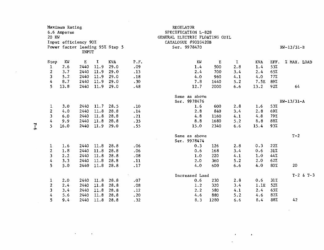
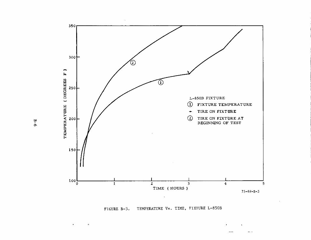
Maximum Rating REGULATOR 6.6 Amperes SPECIFICATION L-828 20 KW GENERAL ELECTRIC FLOATING COIL Input efficiency 90% CATALOGUE #901G420B Power factor leading 95% Step 5 Ser. 99 78470 RW-13/31-B
INPUT
Step KW E I KVA P.F. KW E I KVA EFF. % MAX. LOAD 1 2.6 2440 11.9 29.0 .09 1.4 500 2.8 1.4 53% 2 3.7 2440 11.9 29.0 .13 2.4 700 3.4 2.4 65% 3 5.2 2440 11.9 29.0 .18 4.0 960 4.1 4.0 77% 4 8.7 2440 11.9 29.0 .30 7.8 1440 5.2 7.5E 89% 5 13.8 2440 11.9 29.0 .48 12.7 2000 6.6 13.2 92% 64
Same as above Ser. 9978476 RW-13/31-A
1 3.0 2440 11.7 28.5 .10 1.6 600 2.8 1.6 53% 2 4.0 2440 11.8 28.8 .14 2.8 840 3.4 2.8 69% 3 6.0 2440 11.8 28.8 .21 4.8 1160 4.1 4.8 79% 4 9.9 2440 11.8 28.8 .35 8.8 1680 5.2 8.8 88%
I'Zj 5 16.0 2440 11.9 29.0 .55 15.0 2340 6.6 15.4 93% I
0'\
Same as above T-2 Ser. 9978474
1 1.6 2440 11.8 28.8 .06 0.3 126 2.8 0.3 22% 2 1.8 2440 11.8 28.8 .06 0.6 168 3.4 0.6 31% 3 2.2 2440 11.8 28.8 .08 1.0 220 4.1 1.0 44% 4 3.3 2440 11.8 28.8 .11 2.0 360 5.2 2.0 62% 5 5.0 2440 11.8 28.8 .17 4.0 600 6.6 4.0 80% 20
Increased Load T-2 & T-3 1 2.0 2440 11.8 28.8 .07 0.6 230 2.8 0.6 31% 2 2.4 2440 11.8 28.8 .08 1.2 320 3.4 1.1E 52% 3 3.4 2440 11.8 28.8 .12 2.2 580 4.1 2.4 65% 4 5.6 2440 11.8 28.8 . 20 4.6 880 5.2 4.6 82% 5 9.4 2440 11.8 28.8 .32 8.3 1280 6.6 8.4 88% 42

MAXIMUM RATING REGULATOR 6.6 Amperes Power 20KW SPECIFICATION L-828 Input effeciency 90% GENERAL ELECTRIC FLOATING COIL Power factor at step 5 is min. .95 S er. 99 7 84 72
Green T-4 Step KW E I KVA P.F. KW E I KVA EFF. % MAX. LOAD
1 1.5 2450 11.6 28.4 .05 0.3 100 3.0 0.3 19% 2 1.6 2450 11.6 28.4 .06 0.4 130 3.4 0.4 25% 3 1.9 2450 11.6 28.4 . 07 0.8 180 4.2 0.8 40% 4 2.6 2450 11.6 28.4 .09 1.4 240 5.3 1.3 55% 5 3.6 2450 11.6 28.4 .13 2.5 360 6.5 2.3 69% 13
Increased Load T-4/T-10 1 1.8 2450 11.6 28.4 .07 0.5 200 2.8 0.6 28% 2 2.2 2450 11.6 28.4 .08 1.0 300 3.4 1.0 45% 3 3.0 2450 11.6 28.4 .11 1.8 420 4.2 1.8 59% 4 4.5 2450 11.6 28.4 .16 3.4 630 5.3 3.4 75% 5 6.7 2450 11.6 28.4 .24 5.6 860 6.5 5.6 83% 28
Increased Load T-4/T-10/T-11 1-zj 1 2.4 2450 11.6 28.4 .08 1.2 440 2.8 1.2 49% I -...I 2 3.2 2450 11.6 28.4 .11 2.0 580 3.5 2.0 62%
3 4.4 2450 11.6 28.4 .16 3.3 800 4.2 3.4 74% 4 7.2 2450 11.6 28.4 .25 6.1 1160 5.3 6.1 84% 5 11.1 2450 11.6 28.4 .39 10.0 1560 6.5 10.1 90% 50
Increased Load T-4/T-10/T-11/T-13 1 2.7 2450 11.6 28.4 .10 1.5 560 2.8 1.6 54% 2 3.8 2450 11.6 28.4 .13 2.4 740 3.4 2.5 65% 3 5.3 2450 11.6 28.4 .19 4.2 1000 4.2 4.2 79% 4 8.7 2450 11.6 28.4 .31 7.6 1460 5.2 7.6 88% 5 13.6 2450 11.6 28.4 .48 12.5 1940 6.5 12.6 92% 62

MAXIMUM RATING REGULATOR 6.6 Amperes Power 20KW SPECIFICATION L-828 Input efficiency 90% GENERAL ELECTRIC FLOATING COIL Power factor at step 5 is min. .95 CATALOGUE /I901G420B
Ser. 9978477 Blue T/2 T-5/T-8/T-9
Step KW E I KVA P.F. KW E I KVA EFF. % MAX. LOAD 1 2.5 2450 11.9 29.0 .09 1.2 440 2.8 1.2 48% 2 3.4 2450 11.9 29.0 .12 2.2 640 3.4 2.2 64% 3 4.8 2450 11.9 29.0 .17 3.6 880 4.1 3.6 75% 4 7.4 2450 11.9 29.0 .26 9.7 1280 5.2 6.7 90% 5 13.2 2450 11.9 29.0 .46 12.0 1820 6.6 12.0 91% 60
Ser. 9978471 RW-4/22 1 3.1 2450 11.8 29.0 .11 1.8 700 2.8 2.0 60% 2 4.6 2450 11.8 29.0 .16 3.2 1010 3.3 3.3 71% 3 6.8 2450 11.8 29.0 .26 5.6 1400 4.1 5.7 82% 4 12.2 2450 11.8 29.0 .42 11.0 2160 5.2 11.2 91% 5 20.6 2450 11.8 29.0 .71 19.7 3100 6.5 20.2 95% 98
SPECIFICATION L-828 HEVI-DUTY SATURABLE REACTOR SCRVB*
Ser. A42847-l RW-13 TDZ-1 1 4.2 2440 12.5 30.5 .14 3.0 340 9.5 3.2 93% 2 4.6 2440 13.3 32.2 .14 3.6 360 10.2 3.7 78%
l'%j 3 7.0 2440 15.8 38.4 .18 6.1 500 12.5 6.3 86% I 00 4 14.1 2440 21.3 51.9 .27 11.4 740 15.5 11.5 81%
5 24.0 2440 26.4 64.4 .37 21.8 1100 20.0 22.0 91% 44
Same RW-13 TDZ-2 Ser. A42847-2
1 6.4 2450 12.5 30.6 .21 5.6 660 9.2 6.1 88% 2 9.3 2450 14.0 34.3 .27 8.0 800 10.5 8.4 86% 3 14.9 2450 17.5 42.8 .35 13.1 1060 13.0 13.8 88% 4 25.8 2450 22.0 53.9 .48 22.9 1440 16.0 23.0 89% 5 44.6 2450 27.5 67.3 .66 40.6 2040 20.2 41.2 91%
*MAXIMUM RATING 20 Amperes Input efficiency 93% Power 50KW Power factor at step 5 min .. 95

Maximum Rating REGULATOR 6.6 Amperes SPECIFICATION L-828 20KW GENERAL ELECTRIC FLOATING COIL Input efficiency 90% CATALOGUE II 901G420b Power factor at step 5 is min .. 95 Ser. 9978 473 RW-8/17
Input Output Step KW E I KVA P.F. KW E I KVA EFF. % MAX. LOAD
1 1.8 2500 11.6 29.0 0 06 0.6 200 3.2 0.6 33% 2 2.0 2500 11.6 29.0 .07 0.8 240 3.5 0.8 40% 3 2.3 2500 11.6 29.0 .08 1.1 280 4.0 1.1 48% 4 3.3 250.0 11.8 29.5 .11 2.2 440 5.2 . 2. 3 67% 5 5.2 2500 11.9 29.7 .18 3.8 640 6.3 4.0 65% 19
Increased Load RW-8/17 & STOL 1 2.0 2500 11.6 29.0 .07 0.7 300 2.3 0.7 35% 2 2.4 2500 11.6 29.0 .08 1.1 440 2.6 1.1 46% 3 3.0 2500 11.6 29.0 .10 1.7 540 3.1 1.7 57% 4 5.0 2500 11.6 29.0 .17 3.8 920 4.2 3.9 76% 5 7.0 2500 11.6 29.0 .24 5.8 1160 4.9 5.7(E) 83% (E) Error
28 '"%j I
\0 Same Type as above
Ser. 99748468 T-3/T-6/T-7/T-14 1 3.7 2500 12.0 30.0 .12 2.4 880 3.0 2.6 65% 2 5.0 2500 12.0 30.0 .17 3.8 1120 3.6 4.0 76% 3 6.9 2500 12.0 30.0 .23 5.8 1440 4.2 6.0 84% 4 11.1 2500 12.4 31.0 .36 9.3 1850 5.1 9.4 84% 5 16.8 2500 12.6 31.5 .53 15.5 2560 6.2 15.9 96% 78

APPENDIX G
QUICK REACTION--RADIO REMOTE CONTROL AUGUST 1974

INTRODUCTION
PURPOSE.
In response to a request by the FAA SRDS letter of March 4, 1974, a prototype "Touch-Tone" selective air-to-ground radio remote control system for airport lighting has been developed and flight tested at NAFEC.
DISCUSSION
The system, as presently configured, possesses the following operating characteristics:
1. Usable on any VHF or UHF frequency, AM or FM, depending upon the communication transmitter/receiver used. (The signal is inserted into and extracted from the audio input/output circuits of the equipment, hence is radio frequency non-dependent). Provides remote control from aircraft or ground facility (tower, FSS, etc.).
2. Airport "callup" or designation consists of any two digits of 12 possible, except that double digits (11, 55, etc.,) cannot be used. Permits selection of any one of 132 possible airports.
3. Four separate functions (third digit) are provided to permit selection of any or all of the following:
a. MALS-High Intensity (MediumApproach Lighting) b. MALS-Low Intensity (MediumApproach Lighting) c. RAILS (Runway Alignment Indicator System) d. REILS (Runway End Indicator System)
4. Touch-Tone encoder unit for use in aircraft plugs into standard JJ-033 microphone jack and accepts PJ-068 microphone plug for "thru-unit" operation. No installation cost. Encoder used at NAFEC costs $49.50 retail.
5. Ground installed decoder unit includes time delay relaying to preclude random-noise activation, approximate cost is $200.00.
Our prototype equipment is presently installed and capable of operating the above indicated approach lighting systems serving runway 4 at NAFEC.
It will be maintained in operational status for a period of 3 months to obtain component life data and to provide demonstration capability.
Unless you direct otherwise, we will now consider this effort concluded with regard to further system development, and will only perform such additional work as may be required to maintain the system ih operation.
G-1

APPENDIX H
AIMING POINT LIGHTS SEPTEl-ffiER 1974

INTRODUCTION
PURPOSE.
In order to evaluate the visual a1m1ng point lighting configuration proposed, we have installed the necessary green filters within the runway 13 touchdown zone lighting system at NAFEC. One additional filter, beyond the number recommended, was utilized to extend the vertical leg of each "Tn slightly. Four NAFEC test pilots accomplished 16 daylight simulated Category II approaches and landings to this system using the Convair CV880 aircraft equipped with the recently developed Bendix Cockpit Fog Simulator. In addition to obtaining tape recorded in-flight comments concerning the system effectiveness, we also required that each pilot complete a post-flight questionnaire immediately after termination of each approach series. The pilots were briefed as to the purpose and configuration of the aiming point system prior to each evaluation flight session, and were also afforded several orientation approaches, without visibility restriction, so as to insure that they would recognize the "T" indication under the simulated fog conditions.
DISCUSSION
Results of the evaluation, as obtained from analysis of the recorded comments and completed questionnaires, were unfavorable for the particular configuration evaluated. Use of green filters reduced the intensity of the "T11 lights to approximately 15-20 percent of that of the surrounding unfiltered touchdown zone lights, and pilots commented that the aiming point indication was never identified until well after the runway threshold had been overflown. During several of the approaches and landings the pilots did not visually acquire the "T" lights at all, even though they were looking for them. With the considerably reduced intensity of the green "T" lights, it may even be that none of the subject pilots really did perceive the green lights, but rather that they actually detected the "gap" or "void" in the shape of a "T" created by the arrangement of the very low intensity units. It, of course, is purely supposition, but this possibility was mentioned by the pilots themselves.
At first thought, it might seem that simply leaving a "black hole" gap of disconnected fixtures within the touchdown zone lighting system would serve to identify the desired aiming or touchdown point equally as well as use of differently colored units. This "negative" form of indication does not offer a solution, however, since pilots might very well be confused and/or misguided by false "gaps" or "voids" that occasionally occur as a result of system lamp outages and failures. It appears certain that a bold, "positive" indication must be provided to define this particular point within the touchdown zone, if such indication is required.
Additional filters were subsequently installed in the NAFEC touchdown zone (TDZ) lighting system to permit evaluation of a higher density green lighted aiming
H-1

point indication, i.e., totally green bars within the TDZ system at 900-, 1,000-, and 1,100- foot distances from the runway threshold. This did not provide significant improvement to the indicator system, however, since it resulted only in the appearance of a larger gap within the TDZ system until the pilot was close to the threshold and able to perceive the green lights. There was no reason to expect that three bars of green filtered lights, at a spacing of 100 feet from one another, would prove much more conspicuous than did the original single bar just flight tested. In order for multiple lamp group installations to provide a more bold signal with greater range than that of a single lamp group, the distance or space between groups must be quite close, and certainly less than the 100 feet found between adjacent bars of the TDZ lighting configuration.
While it would be nice to obtain a readily identifiable "point" indication within the existing TDZ lighting pattern by merely installing colored filters in several fixtures, such results cannot be reasonably expected, as our testing thus far has demonstrated. If the indication is to be provided by a change in color, then a major modification of the fixture to obtain greatly increased intensity, or substitution of a larger, more powerful light unit must be anticipated. Such an increase in white light intensity is essential to compensate for the 80-85 percent loss of output incurred with use of the colored filter. At least double the wattage of lamp power would be necessary, and probably a considerably greater increase would be required to make the green indication "stand out" rather than be merely "competitive" with the remaining and surrounding white lights of the TDZ system.
It might be possible to indicate the desired touchdown aiming point by a change to the lighting pattern rather than through a change in color. For example, the bars of light of the TDZ lighting system at the 1,000 feet from threshold might be expanded to form a bar of white lights equally spaced across the total width of the runway. This choice would permit the use of standard TDZ lighting fixtures, since the boldness and identifiability of the indicator would depend upon a difference in configuration rather than upon a change in color. The cost of retrofitting the additional necessary light units within an existing TDZ lighting system would be considerable, however. A "Bar" configuration of this sort could also be used on other than Category II and III runways, since it does not depend upon the existence of a TDZ Lighting System for interpretation.
Either of the alternatives proposed above would entail a significant expenditure of funds, both for development and for installation. It would seem necessary, therefore, that the requirement for such a Touchdown aiming point indicator be established now, from the operational standpoint, so as to justify further developmental effort.
In summary, we must conclude from the preliminary testing of the suggested ·aiming point modifications to the standard TDZ lighting system that no "quick and dirty" minor alteration of the system will provide a usable indicator. We recommend that, considering the probable high cost of development of such an
H-2
indicator configuration, the need for such visual aid or guidance system be absolutely established from an operational point of view. From questionnaire results and discussion of the matter with experienced pilots we feel that there are some valid reasons for continuing with this investigation.
We propose to undertake no further developmental or evaluational effort here at NAFEC until such time as the several questions raised in this report can be considered and resolved.
H-3

APPENDIX I
COCKPIT FOG SIMULATOR NOVEMBER 1974

INTRODUCTION
PURPOSE.
The cockpit fog simulator under evaluation was originally designed for installation in a DC7 type-aircraft. At the time that the original simulator was delivered, a number of mechanical and photometric deficiencies were noted. Since, by that time, it had been determined that the Convair 880 NAFEC aircraft would be the test bed for all CAT II experimental equipment, it was determined that a contract should be established with the original developer, Bendix Corporation, to modify the cockpit fog simulator to correct the deficiencies and to suit it for installation in the 880 jet. The simulator was acceptance tested "on-the-bench" at Bendix prior to delivery to NAFEC in January of 1974. The simulator and associated electronic components were then installed in the Convair 880 at NAFEC for evaluation. Each of the four NAFEC Convair 880 qualified test pilots were given an opportunity to fly the simulator during VFR weather conditions on approaches to the instrument runway at NAFEC to determine the realism of the restricted visibility condition simulated by the equipment. After several approaches, each pilot was asked to give his opinion as to the suitability of the fog simulator for use both as a pilot training aid and as a tool for the evaluation of low visibility visual guidance systems.
The equipment, immediately upon installation in the aircraft, was found to function satisfactorily, and an initial system checkout proved that all previous deficiencies had been corrected. The pilots' comments were, without exception, enthusiastic as to the realistic simulation of an approach conducted under CAT II and III weather conditions. The system was evaluated using all three of the Mylar film tapes provided, CAT II, CAT IliA and CAT IIIB.
The pilots were afforded one familiarization approach with the simulator set for the least restrictive visibility condition, and thereafter accomplished a number of approaches with increasingly restrictive visibility simulation down to and including that of CAT IIIB. As previously stated, the pilots unanimously indicated that the system was an accurate representation of the visibility situation encountered during low visibility approaches.
The fog simulator is eminently suited to testing of visual aids intended for viewing through the frontal wind-screen of an aircraft on final approach for landing. It is particularly well configured for use during precision approaches in that it does not block or restrict the user pilot's clear view of essential cockpit instruments such as the flight director, ILS indicators, etc. Since it has a most restricted peripheral field of view, the simulator is not suited for the evaluation of aids other than those intended to support approach and landing operations; i.e., it does not permit viewing of aids located off to one side or other of the aircraft.
I-1

TEST RESULTS.
Since all comments and test results were favorable, no further evaluation of this simulator device is anticipated. The system will be used, without modification, in the Convair 880 aircraft at NAFEC as an evaluation tool. A study is presently underway to determine the feasibility of installing the system in yet another NAFEC aircraft so that it may be used at times when the Convair 880 is committed to higher priority work.
I-2

APPENDIX J
TAXIWAY GUIDANCE SIGNS NOVEMBER 1974

INTRODUCTION
PURPOSE.
In response to your verbal request, an evaluation of four different internally illuminated taxiway guidance signs was conducted by the Airports Branch, ANA-440, at NAFEC. The signs evaluated were:
1. a modified L-829 sign, 2. a fiber optic sign designed by ATC International, Inc., Tulsa, Oklahoma, 3. a fiber optic sign designed by Standard Signs, Inc., Cleveland, Ohio, and 4. a parabolic reflector-type sign designed by the Structural Electric
Products Company, Windsor Locks, Connecticut.
DISCUSSION
The signs were installed near the intersection of runway 17-35 and taxiway I, approximately 50 feet from the edge of taxiway l.
The location was selected because of the high ambient background brightness of the U.S. Air Guard apron floodlighting system directly behind the displayed signs.
Four range marks were established adjacent to taxiway I at 500-foot intervals between the signs and the intersection of taxiway I and taxiway B, approximately 2,400 feet from the signs (see enclosed map).
Power to illuminate the signs was obtained from the taxiway series lighting circuit by means of isolation transformers.
Taxi runs were started at the intersection of taxiway I and taxiway B under night VFR conditions. Each sign was observed individually recording both the distance at which the sign was first seen and the distance at which the sign became legible. Two aircraft were used for these taxi runs; a Cll3 and a DC6/B.
A total of 11 observers participated in the tests, eight NAFEC pilots and three nonrated personnel from ANA-440.
The data obtained from the taxi runs and the comments recorded indicate that the parabolic reflector sign is far superior to the other three signs in both conspicuity and legibility. This sign was immediately identified as a sign at the start of the run and readily interpreted at ranges of 1,000 to 1,500 feet.
The remaining three signs did not possess the boldness that was demonstrated by the parabolic reflector sign. Without previous knowledge of where to look,
J-1

these signs would be most difficult to locate. The modified L-829 sign produced a bright spot (hot-spot) in the center of the character that reduced the legibility and made the sign indistinguishable until the observer had advanced to a point approximately 500 feet from the sign. The fiber optic sign designed by Standards Signs, Inc., employed an illuminated light bar above the legend which produced a glare on the top portion of the sign. This caused difficulty in reading the legend. This sign was not legible at ranges greater than 1,000 feet. The fiber optic sign designed by ATC International, Inc., was distinct and easily interpreted at approximately 1,000 feet but was not considered conspicuous enough to attract attention under high ambient lighting conditions.
It was concluded that a sign displaying a lighted background, such as the parabolic reflector sign, would prove most effective in commanding a pilot's attention while providing more than adequate legibility. The other sign types, while having sufficient legibility, were noticeably lacking in conspicuity.
J-2

CONTIIOl TOWER.
X LOCATION OF SIGNS RAMP SPEED 10 MPH e 500 FOOT RANGE MARKS
0 100 1000 1 I I I I I I I I I
SCALE fEET
NAFEC/ATLANTIC CITY AIRPORT. ATLANTIC CITY, NEW JERSEY 75-69-J-1
FIGURE J-1. l1AP OF NAFEC AIRPORT WITH LOCATION OF SIGNS AND RANGE MARKS
J-3

APPENDIX K
QUICK REACTION TO FIELD-ENCOUNTERED PROBLEMS (EVALUATION OF OMNIDIRECTIONAL STROBE LIGHTS)
DECEMBER 1974

INTRODUCTION
PURPOSE.
The purpose of this effort was to evaluate the suitability of the Visual Vector model 1800 omnidirectional condenser-discharge "strobe" units as part of the medium intensity approach light system with runway alignment indicator light system (MALS/RAILS). Since these strobe units have already been approved for use in visual flight rules (VFR) weather conditions, this limited test was intended to determine, under actual low-visibility weather conditions, whether they are sufficiently intense to provide adequate approach guidance in instrument flight rules (IFR) conditions to a minimum of Category I (200-foot ceiling/1/2-mile visibility).
BACKGROUND.
A standard 5-unit RAILS system was installed as an adjunct to the MALS configuration already serving runway 4 at NAFEC. The visual vector omnidirectional strobe units were located on 200-foot centers starting at a point 1600 feet from the runway threshold and terminating at a distance of 2400 feet. A NAFEC aircraft (Aero Commander N-477 and FAA test pilots were placed in a "weather standby" status so that advantage might be taken of any actual Category I weather occurrences at NAFEC. In addition to the two subject pilots, a project observer accompanied each flight to record in-flight comments concerning system performance.
DISCUSSION
Approximately 25 Category I approaches in ceilings from 500 to 200 feet and visibilities of 3 miles to one-half mile were accomplished during a period of 4 months. Six NAFEC pilots participated and rendered tape-recorded comments and opinions as to omnistrobe performance after each individual approach. Although the strobes may be operated on either of two intensity settings (high or low), only the highest intensity step was utilized during this evaluation.
After 19 actual weather approaches had been accomplished, the consensus of pilot opinion was that the strobe units were, at best, only marginally suited for support of straight-in precision approaches under the Category I weather conditions flown. While the performance of the strobes appeared to increase with lowering visibilities and background ibrightness, they still were not sufficiently intense to provide the necessary early identification and visual contact within the entire range of Category I conditions.
At about the same time as this determination had been made, the manufacturer, Unitron International Systems, Inc., completed development of a field modification intended to increase the effective intensity of their standard units by approximately 50 percent. The NAFEC test units were subsequently fitted
K-1

with the modification and subjected to further evaluation.
Additional flight evaluation of the modified strobe units was accomplished on November 20, 1974, when weather approximating the lower segment of Category I conditions (200- to 300-foot ceilings and 1/2- to 1-mile visibilities) occurred. Pilot opinion, from individuals who had previously observed the performance of the original strobe installation and found it to be wanting, was unanimous in judging the system to be greatly improved in intensity. They also thought it adequate for support of approach and landing operations in reduced visibility conditions as low as that of Category I.
It should be noted, however, that the system modification, while providing the necessary increased intensity and conspicuity, was not tested for durability and/or reliability. The units which ultimately provided the necessary Category I visual guidance were not production equipment, and should be subjected to additional environmental testing.
K-2

APPENDIX L
NONPRECISION APPROACH RUNWAY LIGHTS FEBRUARY AND APRIL 1975

INTRODUCTION
PURPOSE.
An evaluation program was undertaken to determine the adequacy of guidance provided the pilot for nonprecision instrument approaches by runway edge and threshold lights employing omnidirectional lenses and vehicular traffic-type lamps. Approaches were flown at night using 40-watt traffic lamps as approach runway light sources by several aircraft on four different occasions when the weather varied from a reported 2 1/2-mile visibility up to near VFR conditions. The 40-watt omnidirectional runway lights were observed at maximum range on approaches offset from the runway centerline by 30° and during circling approaches.
DISCUSSION
Seven pilots flying on four different nights provided 13 sets of observations. The consensus of opinion was that the omnidirectional 40-watt lights provided adequate range of detection including the green threshold lights. When approached from a direction offset 30° from the extended centerline, the guidance received from the omnidirectional lights was judged to be adequate to support the continuation of the approach. This indicates that the runway was seen as a run-way and the directional guidance provided was judged sufficiently distinctive to support the flight corrections required for runway alignment. Both the brightness of the 40-watt lights and the continuity of guidance were judged adequate during circling approaches.
In light of these favorable statements, the evaluation laid down in the Resume will be continued. Flight time so far was limited due to lack of proper weather conditions. In addition, the tests did not commence until January 1975 due to lack of proper weather conditions. In addition, the tests did not commence until January 1975 due to the excessive lead-time required to purchase lighting fixtures and their accessories. Our next course of action and primary interest is to determine if under adverse conditions of 500-foot decision height and 1-mile visibility the 40-watt light source will be satisfactory. If this is the case, then a light source of lower wattage will be tested until optimum source is determined. If the 40-watt source is not considered sufficient, then a light source with a higher output will be tested. Activity results will be documented as informqtion becomes available on individual light sources and a formal report will be issued when all the work is completed.
L-1

INTRODUCTION
PURPOSE.
The following summarizes guidance tests of a low-cost omnidirectional runway light system conducted in the 2 months since our letter report of February 11, 1975. The objective has been to determine the adequacy of visual guidance provided by vehicular type traffic lamps used in runway lights and to determine the lamp intensities related to power required to produce a reasonable balance between edge and threshold lights. While the earlier report covered tests of 40-watt lamps and indicated favorable response to the guidance value of that intensity, the later tests have included both lower and higher intensity lamps (15, 25 and 69 watts). The tests were conducted in VFR conditions at dusk and on nights with a bright moon. More restricted visibility conditions, down to 1 mile, were not available during the reporting period. The method called for pilots to judge the adequacy of the visual guidance at maximum range and throughout approaches offset 30° and during circling approaches.
DISCUSSION
The lowest power lamps tested were 15 watts installed in runway edge lights and as one-half of the threshold, and 25-watt lamps making up the other half of the threshold. Twelve pilots, including seven general aviation and five NAFEC professional pilots, observed this minimum system. The judgments were that the system was marginally adequate in range, about 1 to 1-1/2 miles, and for approach guidance in the moderately bright surrounding conditions. The 15-watt lamps on one side of the threshold were, however, rated inadequate, while the 25-watt lamps on the other side of the threshold were rated marginally adequate for use with the 15-watt clear-edge lights in this lighted area.
As a result of interspersed approaches made with the standard medium intensity runway lights (MITL), the MIRL's were reported to be about equal in brightness to the 15-watt edge and 25-watt threshold system when the MIRL's were set on step 4, an intermediate setting. On a lower setting, step 3, the MIRL's were rated inadequate for offset and circling approaches. The pilots indicated a preference for the more even brightness of the omnidirectional lights.
The next grouping was one with 25-watt lamps in both the edge and threshold positions. Seven pilots, including five with general aviation backgrounds, judged the guidance of this system to be adequate, the detection range being about 5 miles in VFR conditions. On offset and circling approaches the 25-watt lights appeared to be about equal in brightness to the MIRL system when the latter was on brightness step 4.
The final system tested provided 69-watt lamps for edge lights and for one side of the threshold and 116-watt lamps making up the other half of the threshold. Five pilots, including two general aviation pilots, reported the 69-watt lamps to produce adequate guidance for the circling and offset
L-2

approaches. To the pilots the two halves of the threshold (69- and 116-watts) appeared equivalent. Clearly, in these VFR conditions this maximum omnidirectional system provided a clear signal in the NAFEC airport environment, the detection range being from 5 to 7 miles. Brightness of the 69-watt system was roughly equivalent to the MIRL's on the manimum setting, step 5, when outside the main MIRL beam. Photometric data correlating power source and intensity distribution is available and will be published at the completion of this activity.
It should be noted that all detection ranges reported herein may tend toward maxima since familiarity with the airport and surrounding area tended to make available' to the pilots valuable "where-to-look" clues. The itinerant general aviation pilot approaching an unfamiliar airport would probably experience more uncertainty in runway identification at these ranges.
The following tentative conclusions may be considered based on all the judgments and pilot comments received to date. Either the 15-, 25-, 40- or 69-watt vehicular type traffic lamps with omnidirectional lenses will provide adequate visual guidance for offset and circling approaches when there is a reasonable fit with the visibility conditions and the brightness of the area surrounding the runway. In a dark area the 15-watt lamps paired with 25-watt threshold lights would be adequate. The 25-watt edge lights are adequate for VFR conditions in areas with medium brightness such as the present test site. In areas of higher brightness for maximum reach in reduced visibility conditions, either the 40- or the 69-watt lamps may be preferred. Testing will be continued with a goal of determining the minimum adequate lamp intensity in conditions of 1 mile visibility, and all the results will be documented in a formal report upon activity completion.
L-3
APPENDIX M
CATEGORY III LIGHTING SYSTEM APRIL 1975

INTRODUCTION
PURPOSE.
The purpose of this activity was to determine the compatibility of runway edge lights with runway centerline lights and touchdown zone lights in CAT II and III weather conditions.
BACKGROUND.
A letter from ARD-1 to ANA-l, dated November 5, 1973, mentions previous tests of the "Balanced Lighting System" that had been conducted by NASA Ames Research Center in the FAA fog chamber. These tests were conducted under simulated CAT I, II, and III weather conditions. In that letter it was requested that the NAFEC CAT III Lighting System under Activity 073-323-010 be expanded to obtain data on the visibility of the standard FAA approved runway centerline lights, edge lights and touchdown zone lights under actual CAT II and III weather conditions. Since the previous observations under simulated conditions were made from 54.1 (scale) feet above the runway, it was desirable to collect real weather data at this height.
The FAA Systems Research and Development Service suggested testing of these systems to determine whether they possess the necessary over-design qualities to suit them for use in the lower visibility situation using both 25-- and 50-foot spacing on the centerline.
DISCUSSION
The runway edge lights are 200-watt L-819 above-ground fixtures extending the length of the runway on either side having 200-foot spacing where practicable. The centerline lights are 200-watt L-850A in-pavement fixtures extending the length of the runway with the capability of being operated only on 25- or 50-foot spacing. The touchdown zone lights, three fixtures to a bar, located on either side of the runway centerline, are 300-watt 1-838 Type II in-pavement fixtures, and they extend down the runway for 3,000 feet. These fixtures are in lOD-foot spacing.
Since it was necessary to observe and record the number of edge lights, centerline lights and touchdown zone lights visible to a pilot prior to landing, high lift equipment was employed to simulate aircraft height while passing the runway threshold. The high lift equipment was located in line with the runway enterline at the threshold. Activity observers were elevated to a height of approximately 54 feet above the runway. Observations were made during periods of low visibility using both 25- and 50-foot spacing on the centerline lights. As the distance viewed by the observer became greater, the difference between the 25- and the 50-foot spacing became less noticeable. At approximately 1,300 feet, the lights appeared to blend together presenting to the observer an extended bar of light. From the foregoing information, it was determined
M-1

that 50-foot spacing is adequate for CAT II operations.
The data collected under these periods of low visibility conditions were used to plot the graphs shown in figures M-1 and M-2. These graphs represent the distance to which the farthest centerline light and touchdown zone light could be observed, and is given as a percentage of the distance to which the runway edge lights (a competitive standard in this case) could be observed under the given visibility restriction and intensity step of the systems. Graphs of figures M-1 and M-2 are attached.
It can be seen by the graphs that the majority of the observations recorded fall between the 75 and the 100 percent scale indicating that the systems were fairly well balanced in the intermediate visibilities (300 feet to 1,800 feet). In the lower visibilities, the touchdown zone and the centerline lights are more effective. As the visibility increased the edge lights became more effective.
It was concluded from these tests that the present runway lighting systems are adequate for operations in the CAT II and III weather conditions.
~2

150--------------------------------------------------------------------------------l
Cl)
E-< :r: Q ...:l lil
~ 100 ~ lil E-< z lil l)
~ 75
>< E-< ...... ...:l ...... Ill ..... Cl)
~ ..... 50 > w
E-< z lil l)
~ lil ~ 25
0 0 400 800 1200 1600 2000
EDGE LIGHT DISTANCE IN FEET 75-69-M-1
FIGURE M-1. CENTERLINE INSET LIGHT VISIBILITY AS PERCENTAGE OF EDGE LIGHT VISIBILITY

125----------------------------------------------------------~
U)
E-< ::t 0 ...... ~ N 0 E-<
r... 75 0 >-E-< ...... ~ ...... ~ ...... U) 50 ...... >
T E-< .j:>o z
~ () ~ ~ 0.. 25
0o 400 800 1200 1600 2000
EDGE LIGHT DISTANCE IN FEET
75-69-M-2
FIGURE M-2. TOUCHDOWN ZONE LIGHT VISIBILITY AS PERCENTAGE OF EDGE LIGHT VISIBILITY