1988 prototype absorbers
TRANSCRIPT

8/6/2019 1988 Prototype Absorbers
http://slidepdf.com/reader/full/1988-prototype-absorbers 1/14
BBC RD 1988/5
~
~1 98 7
lJ1lJ1B---
ResearchDepartment
ReportJune 1988
THE DEVELOPMENT OFPROTOTYPE ABSORBERS WITHVARIABLE CHARACTERISTICS
E.W. Taylor, M.A. (Cantab.), C.Eng., M.I.E.E., K.F.L. Lansdowne, and
R.J. Peill, B.Sc.
Research Department, Engineering Division
THE BRITISH BROADCASTING CORPORATION

8/6/2019 1988 Prototype Absorbers
http://slidepdf.com/reader/full/1988-prototype-absorbers 2/14
BBC RD 1988/5
THE DEVELOPMENT OF PROTOTYPE SOUNDABSORBERS WITH VARIABLE CHARACTERISTICS
E.W. Taylor, M.A. (Can'ab.), C.Eng., M.I.E.E., K.F.L. Lansdowne,
and R.J. Peill, B.Sc.
Summary
The development of two prototype sound absorbers with controllable absorption
characteristics is described One of these absorbers gives control of sound absorption at
predominantly low frequencies (up to 250 Hz;' while the other operates at frequencies
above this value. The low-frequency absorber is constructed in modular form, while the
high-frequency absorber takes the form oj a false ceiling to the treated room. Factors
which are required 10 ensure the consistency oj the absorption characteristics given by
these absorbers are discussed
Issued under the Authority of
Research Department, Engineering Division,BRITISH BROADCASTING CORPORATION Head of Research Department
(PH-291) June 1988
8/6/2019 1988 Prototype Absorbers
http://slidepdf.com/reader/full/1988-prototype-absorbers 3/14
© British Broadcasting Corporation
No part of this publication may be reproduced, stored in a
retrieval system, or transmitted in any form or by any
means, electronic, mechanical, photocopying, recording,or otherwise, without prior permission.
8/6/2019 1988 Prototype Absorbers
http://slidepdf.com/reader/full/1988-prototype-absorbers 4/14
(PH-291)
THE DEVELOPMENT OF PROTOTYPE SOUND ABSORBERSWITH VARIABLE CHARACTERISTICS
E.W. Taylor, M.A. (Cantab.), C.Eng., M.I.E.E., K.F.L. Lansdowne,
and R.J. Peill, B.Sc.
1. Introduction. . . . . . . . . . . . . . . . . . . . . . . . . . . . . . . . . . . . . . . . . . . . . . . . . . . . . . . . . . . . . . . 1
2. Controllable High-frequency Absorber. . . . . . . . . . . . . . . . . . . . . . . . . . . . . . . . . . . . . . 1
2.1 The false ceiling . . . . . . . . . . . . . . . . . . . . . . . . . . . . . . . . . . . . . . . . . . . . . . . . . . . . . . . . . 1
2.2 Design and performance of prototype absorber. . . . . . . . . . . . . . . . . . . . . . . . . . . . . . . 2
3. Controllable Low-frequency Absorber 5
3.1 Design considerations. . . . . . . . . . . . . . . . . . . . . . . . . . . . . . . . . . . . . . . . . . . . . . . . . . . . 5
3.2 Design and perlormance of prototype absorber. . . . . . . . . . . . . . . . . . . . . . . . . . . . . . . 5
4. Discussion. . .... . . . . .. .. . ... . .. . .. . . . ... . . . . . .. . .. ..... ... . ... . ..... . . . .. . 7
5. Conclusions. . . . . . . . . . . . . . . . . . . . . . . . . . . . . . . . . . . . . . . . . . . . . . . . . . . . . . . . . . . . . . . 9
6. References. . . . . . . . . . . . . . . . . . . . . . . . . . . . . . . . . . . . . . . . . . . . . . . . . . . . . . . . . . . . . . .. 10

8/6/2019 1988 Prototype Absorbers
http://slidepdf.com/reader/full/1988-prototype-absorbers 5/14
THE DEVELOPMENT OF PROTOTYPE SOUND ABSORBERS WITHVARIABLE CHARACTERISTICS
E.W. Taylor, M.A. (camab.), C.Eng., M.I.E.E., K.F.L. Lansdowne, and R.J. Peill, B.Sc.
1. INTRODUCTION
This Report discusses the design of sound
absorbers having variable absorption characteristics,
which were developed during the design of a studio
for the performance of music over (he complete range
from "classical" to "pop" and by a number of
musicians from around four up to forty or perhaps
even m ore. Ideally, differing types of music require a
different acoustic environm ent for their perform ance,
and this consideration suggested the provision of
"variable acoustics" (an ability to change the sound
absorption, and therefore the reverberation time, to
suit the music being performed). This facility would
also have enabled changes to be made in the sound
absorption to compensate for the Dumber of people in
the studio, which could have been a significant factor
for the larg er n um bers of p erfo rm ers env isag ed .
In simple terms, the required change in sound
absorption may be achieved by treating part of the
surface (the ceiling, for exam ple) w ith m aterial of high
absorp tio n, an d arrang ing tha: this can be covered by
moveable panels (the "false ceiling" in the above
exam ple) of low absorption to increase the reverbera-
tion time. This approach has the disadvantage tbat anincrease in reverberation time corresponds w ith a
reduction in the volume of the studio. A ttempts to
provide a long reverberation time in an enclosure of
sm all volum e can lead to problem s of tonal coloration,
and a psychological conflict between two factors: tbe
relatively slow sound decay on tbe one hand. and the
pattern of sound reflections typical of a small and
u su ally r ela tiv el y non-reverberant room on the other.
In the present case the volume of the studio was only
1065 m', even in the absence of the false ceiling,
falling to 804 m ' with the false ceiling in place (the
large void above the false ceiling was required to
accom modate ventilation ductwork). An alternative
approach was therefore studied, in which the false
ceiling carried sound absorbing m aterial on its lower
surface. Moving the false ceiling into place then
sim ultaneo usly in trod uced ex tra ab sorp tion an d red uced
the volume of the studio. In this way the concept of
the false ceiling was retained, but the condition of
short reverberation time now corresponded to the
con ditio n o f sm aller stu dio v olu me.
The m ost practicable form of acoustic treatm ent
for the false ceiling was a layer of porous material
applied directly to its lower surface. This form oftreatment provides predom inantly m id- and high-
(PH-291)
frequency absorption, the low -frequency cut-off poimof the absorption characteristic being determ ined by
the thickness of the porous blanket. Controlled
variation of tbe low-frequency absorption in the
studio, in step w ith the movement of the false ceiling,
was therefore also required in order to achieve a
reason ab ly flat rev erb eratio n-tim e ch aracteristic un der
both the long and the short reverberation-time
conditions. A design of "m odular" low-frequency
absorber (i.e, an absorber in the form of a box of a
standard size, which can be prefabricated away from
the building site) was d ev elo pe d, whos e c ha ra cte ris tic s
could be controlled by covering or uncovering the
front of the absorber (see Section 3). With the
add ition of som e con vention al (non- v ar ia ble ) a co us ti c
treatm ent to give appropriate absorption at th e lo ng er
reverberation time, it was thought that satisfactory
overall absorption characteristics could be achieved in
this way to give "short" and "long" reverberation
tim es of 0.6 sec and 1.2 sec respectively.
In the event, the idea of providing variable
acoustics in this particular studio was abandoned and
the possibility of testing the overall design concept w as
therefore lost. N evertheless, the factors involved in the
design and construction of the separate high and low-frequency absorbers were investigated in detail, and
form th e subject-m atter o f this R ep ort.
The absorption coefficient measurements
described in this Report were made using the con-
v en tio nal re ve rb era tio n-ro om p ro ce du re 1. The volum e
of the reverberation room was 106 r n ' . This is rather
sm all for reliable measurem ents below about 200 Hz2a
because of the comparatively w ide spacing of modal
frequencies below this value. In the development of
th e low -frequency controllable absorber, discussed in
Section 3, this lim itation w as a disadvantage although
it was still possible to com pare results obtained using
different absorber design details. Some departure of
practical absorber perform ance from that predicted by
the test results m ay, how ever, occur, particularly if the
absorbers are used in a room of much greater volume
than the one in w hich th ey w ere m easured.
2. CONTROLLABLE HIGH-FREQUENCYABSORBER
2.1 The false ceiling
The false ceiling was designed as an array ofpanels (Fig. 1), the underside of each panel being

8/6/2019 1988 Prototype Absorbers
http://slidepdf.com/reader/full/1988-prototype-absorbers 6/14
covered with a blanket of absorbing material. In this
design, pairs of panels were hinged together (not
shown in detail in Fig. 1) and arranged so that they
could be "unfolded" to expose the absorbing material
or "folded up" to obscure it. Two of the panel pairs
are shown folded up in Fig. 1, the rest being unfolded.
Angled side-cheeks were to be provided on each
panel, so that when folded up the hard surfaces of the
panel pairs did not hang paraUel to each other: this
was to avoid any possibility of tonal coloration in the
studio caused by multiple reflections between the
panels. The means by which the panels would be
folded up and unfolded was not considered in detail,
although one possibility would have been cables
attached to the panels and actuated by small w inches.
The whole structure was to be stabilized by an open
framework which carried the hinges between pairs of
panels, and which provided apertures against which
the panels fitted w hen they w ere unfolded.
suspended from the ceiling of a reverberation room in
either the unfolded or folded-up condition (Fig. 3) .
Fig. 4 shows the sound absorption character-
istics that were obtained with the pane1s suspended as
described above, both unfolded (curve (a)) and folded
up (curve (b)). In this context it should be noted that
the same absorber area (that of the unfolded panels)
was used in the calculation of the absorption
coefficients in both cases, as this enables a direct
comparison to be made of the overall absorption
obtained under each condition. The effectiveness of the
"folding absorber" design in controlling sound
absorption above 200 H z is immediately apparent.
The measurements of absorption coefficient
with the panels in the folded-up condition were made
with the gap where the side- and end-cheeks of the
panels were nom inally in contact sealed with adhesive
~1~~ound absorbing material .
2.2 Design and performance of prototype
absorber
Four prototype pairs of absorbing panels were
constructed to investigate the sound absorbing prop-
erties of the false ceiling. Each panel (Fig. 2) was
made of 3,4-inch (19 mm) chipboard (except for the
end member carrying the hinges which was made
from wood for greater strength). The absorbing
material, of dimensions 600 mm X 1200 m, was a
blanket of "low-density" (50 Kgm -3) mineral wool
30 mm thick, retained by a welded steel grid mesh of
h-inch (12 mm) pitch. Ring bolts were provided near
each corner of each panel so that they could be
(PH-291 )
F ig. IA rr an gemen t o f p an els in fa ls e c eilin g:
A - Unfolded pair of panels.
B - Folded-up pair of panels.
C - Une of hinges.
D - Angled side-cheeks.
E - Void above false ceiling.
F - Framework.
tape. The importance of this precaution is shown in
Fig. 5, which compares the absorption coefficients
found with and without this seal (curves (a) and (b)
respectively). W ithout the seal, the folded-up pair of
panels tend to act as a resonant cavity absorber,
perhaps with the resonant frequency influenced by the
absorber structure as well as the mass of air inside the
cavity. This gives rise to the enhanced absorption at
low frequencies. In a practical implem entation of this
d esign it w ould be im portant to observe the precaution
of sealing the gap where the folded-up panels m eet.
The nature of the sound field in which the
absorbers are placed can also influence the amount of
- 2 -
8/6/2019 1988 Prototype Absorbers
http://slidepdf.com/reader/full/1988-prototype-absorbers 7/14
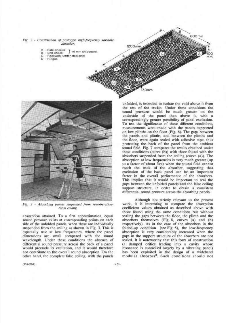
Fig. 2 - Cons tr uc tio n o f p ro to ty pe h ig h- fr eq ue nc y v ar ia bleabsorber.
A - Side-cheeks } 9 ~. ~ .B _ End-cheek ., mm chipboard.
C - Rockwool under steel grid.
D - Hinges.
Fig. 3 - A b so rb in g p an els su sp en de d fr om re ve rb era tio n-
room ceil ing .
absorption attained. To a first approximation, equal
sound pressure exists at corresponding points on each
side of the unfolded panels, when these are individually
suspended from the ceiling as shown in Fig. 3. This is
especially true at low frequencies, where the panel
dimensions are small compared with the sound
wavelength. Under these conditions the absence of
differential sound pressure across the back of a panelwould preclude its excitation, and it would therefore
not contribute to the overall sound absorption. On the
other hand, the complete false ceiling, with the panels
(PH-291)
unfolded, is intended to isolate the void above it from
the rest of the studio. Under these conditions the
sound pressure would be much greater on the
underside of the panel than above it, with a
correspondingly greater possibility of panel excitation.
To test the significance of these different conditions,
measurements were made with the panels supported
on low plinths on the floor (Fig. 6). The gaps betweenthe panels and plinths, and between the plinths and
the floor, were again sealed with adhesive tape, thus
protecting the back of the panel from the ambient
sound field. Fig. 7 compares the results obtained under
these conditions (curve (b)) with those found with the
absorbers suspended from the ceiling (curve (a». The
absorption at low frequencies is very much greater (up
to a factor of about five) when the sound field cannot
reach the back of 'the absorber, suggesting that
excitation of the back panel can be an important
factor in the overall performance of the absorbers.
This implies that it would be important to seal the
gaps between the unfolded panels and the false oeiling
support structure, in order to obtain a consistentdifferential sound pressure across the absorbing panels.
Although not strictly relevant to the presentwork, it is interesting to compare the absorption
coefficient values obtained as described above with
those found using tile same conditions but without
sealing the gaps between the floor, the plinth and the
absorbers themselves (Fig. 8, curves (a) and (b)
respectively). As in the case of the absorbers in the
folded-up condition (see Fig. 5), the low-frequency
absorption is very considerably increased when the
gaps in the support structure of the absorbers are not
sealed. It is noteworthy that this form of construction
(a damped orifice leading into a .cavity whose
resonance is controlled largely by a vibrating panel)
,has been exploited in the design of a wideband
modular absorber', Such conditions should not
- 3 -

8/6/2019 1988 Prototype Absorbers
http://slidepdf.com/reader/full/1988-prototype-absorbers 8/14
I I I I
/- - . . . .'" r--- _ . .
. . .
/
!/
I
/.'" 1:--0.. ~~
,
_ ~1;" ,
..,..-0-""0- .0- ..0--< [)--0--0-'"f>--a'
> - -0--0-...I : > -L L L L L L I I I L
c.90·4-... . .oCJ)
. g 0·2
o63 125 250 500 2kk 4k Bk
fre q u en cy I Hz
80 1:)0 160 2.00 315 400 630 BOO 1·2k 1·61< 2·51< 3·1k 51<6·31< 10k
63 125 Bk50 500 1k
frequency, Hz
2k 4k
(PH-291 ) -4-
Fig. 4 - Results obtained with panels
s us pe nd ed f rom r ev er be ra tio n-r oom c eil in g .
(a) -- Panels unfolded.(b) C>- -0 Panels folded up.
Fig. 5 - Effect of sealing gap between
side- an d e nd -c he ek s o f h ig h-fre qu en cyabsorber.
The curves do not differ siqniticantly above
400 Hz.
(a) c--o Seals present.
(b) , ., ... ._. .: , Seals absent.
-
Fig. 6 - Absorbing pa nels su pp orted o nlow plinths, on r ev er be ra tio n r oom f lo or .

8/6/2019 1988 Prototype Absorbers
http://slidepdf.com/reader/full/1988-prototype-absorbers 9/14
1'050 SO 100 160 200 315400 630800 1·210;ik 25« 31k 5 1 0 . 6·3k 10k
Fig. 7 - Effect of protecting backs of - 0·8high-frequency absorbers from am bient c u
'0sound field.
-he curves do not differ significantly above II,)
o 60630 Hz. 0
(a)-acks exposed to ambient c
sound field.0
OA-b) . . . . . . . . Backs protected from ambient c.~sound field. 0
II'J
.00·2
0
I
I- . . ~ -v , ?
_~. . r---
..l-
f ' J . " .//.. , - ~. . . . V; . . . . . .
/t
_ . . . . . V63 125 250 4k 8k00 1 k 2k
frequency. Hz
50 60 100 160 200 315 400 630 800 1·21<1-6k 2 ·5k 31k 5k 63k 10k
Fig. 8 - E ffect of sealing cavity behindh igh -f requency absorber .
The curves do not differ significantly above
630 Hz.
(a) Cavity sealed.
(b) Cavity not sealed.
1·
- O·cQ)
'0
- o·80
c0 o ·c.~5 !.0
o ·
a
./1'. . . . . . . . . . . -
8v " . . . . . . _ . . . . .
7/ . . . . . . . . . . . . . . . . . . - - ~ . . . -'I
~,' . . . . ! - -
i (I ,
6"'~ , .
!
\..'"l.~
I
f .,.....'1l
4 i. . . . . . . . . . r
. . . . IP- . . .
f> ~ -t
063
however be allowed to occur inadvertently, suggesting
a further reason for sealing the gaps between the
unfolded panels and the false ceiling support structure.
.3. CONTROLLABLE LOW-FREQUENCYABSORBERS
3.1 Design considerations
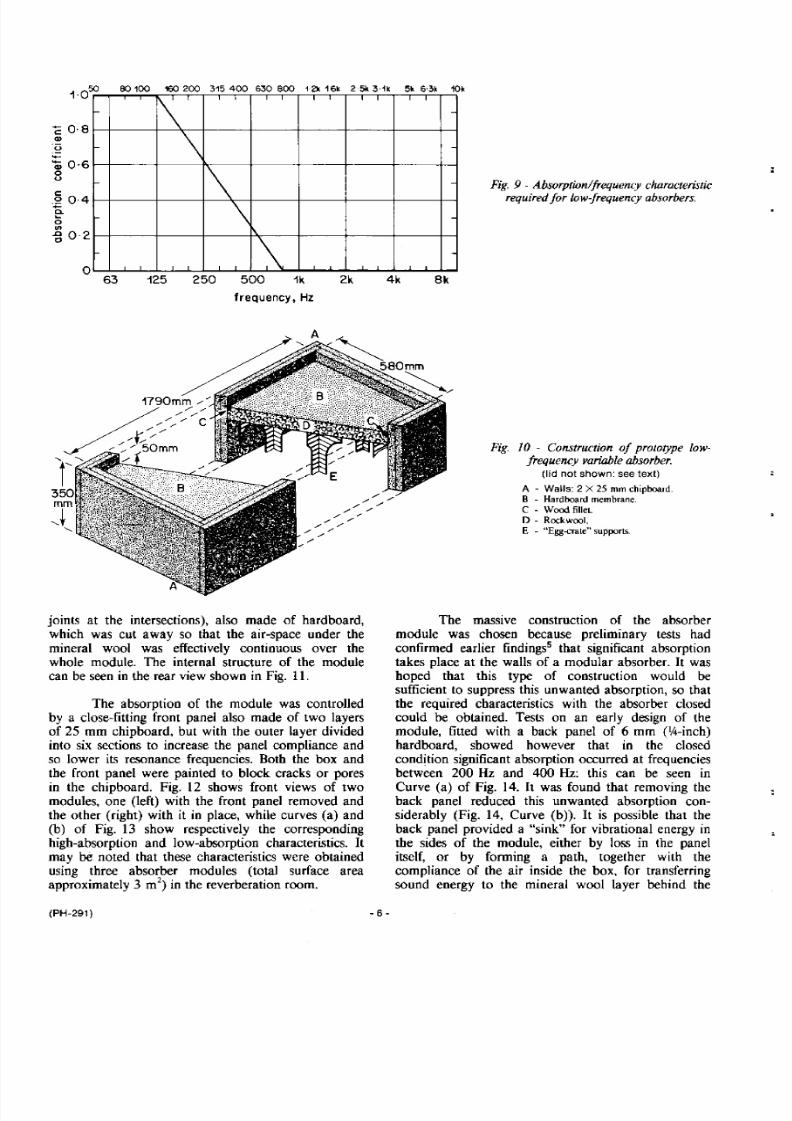
Inspection of Fig. 7 shows that a low-
frequency absorption characteristic of the form shown
in Fig. 9 is required to obtain the same absorption at
all frequencies when the false ceiling is unfolded. The
design which was adopted in the present case was
based on the so-called "D2" modular absorber (a
variant of the A2 modular absorber" with extended I
low-frequency absorption) as used in Studio 7,
Manchester. With the false ceiling folded up, its
absorption is low at all frequencies and ideally the
low-fequency absorbers should then have similar
characteristics. This was achieved by covering the
front of the absorber with a panel of material havinglow absorption at all frequencies. It may be noted that
(PH-291 )
125 250 2k 4k 8k00 1 kfrequency, Hz
the terms "absorber open" and "absorber closed" are
used to denote the absence and presence of this panel
respectively.
3.2 Design and performance of prototypeabsorber
The prototype low-frequency variable absorber
module (Fig. 10) consisted of a box of internaldimensions 1790 mm long, 580 mrn wide and 350 mm
front-to-back, For reasons discussed below, this box
was of rather massive construction: it was made of
two layers of 25 mm (l-inch) chipboard bonded
together, thus giving an overall surface density of
35 kg m-2. Furthermore, no back panel was provided,
and the box was sealed to the room surface on which
it was mounted. A membrane of plain hardboard
3.2 rnm (Ih-inch) in thickness was mounted 50 mm
from the front edge of the box using a wood fillet, and
this sheet was backed by a layer of low-density
(50 kg m-3) mineral wool 30 mm thick. The mineral
wool layer was supported by an "egg-crate" structure(intersecting sheets of thin material with "halving"
- 5-
8/6/2019 1988 Prototype Absorbers
http://slidepdf.com/reader/full/1988-prototype-absorbers 10/14
1.050 80 100 160 200 315 400 6:50 900 12k 16k 25113·1k 5k 6·3k 10k
c o-sQ)
r- 1 \\
\\
1\
\
u
-Q j 0·6ou
c.2 004-L. . .o
'"- g 0·2
a63 125 250 500 1 k 2k
frequency. Hz
4k 8k
jomts at the intersections), also made of hardboard,
which was cut away so that the air-space under the
mineral wool was effectively continuous over the
whole module. The internal structure of the module
can be seen in the rear view shown in Fig. 11.
The absorption of the module was controlled
by a close-fitting front panel also made of two layers
of 25 mm chipboard, but with the outer layer divided
into six sections to increase the panel compliance and
so lower its resonance frequencies. Both the box and
the front panel were painted to block cracks or pores
in the chipboard. Fig. 12 shows front views of two
modules, one (left) with the front panel removed and
the other (right) with it in place, while curves (a) and
(b) of Fig. 13 show respectively the corresponding
high-absorption and low-absorption characteristics. It
may be noted that these characteristics were obtained
using three absorber modules (total surface areaapproximately 3 m") in the reverberation room.
(PH-291)
Fig. 9 - Absorpt ion/frequency characteris t ic
r eq ui red f or low -fr eq uency absorbe rs .
Fig. 10 - Construction of prototype low-fr eq uency var ia bl e a bsorbe r.
(lid not shown: see text)
A - Walls: 2 X 25 mm chipboard.
B - H ard bo ard m em brane.
C - Wood fillet,
D - Rockwool,E - "Egg-crate" supports .
The massive construction of tbe absorber
module was chosen because preliminary tests had
confirmed earlier findings! that significant absorption
takes place at the walls of a modular absorber. It was
hoped that this type of construction would be
sufficient to suppress this unwanted absorption, so thatthe required characteristics with the absorber closed
could be obtained. Tests on an early design of the
module, fitted with a back panel of 6 mm (V4-inch)
hardboard, showed however that in the closed
condition significant absorption occurred at frequencies
between 200 Hz and 400 Hz: this can be seen in
Curve (a) of Fig. 14. It was found that removing the
back panel reduced this unwanted absorption con-
siderably (Fig. 14, Curve (b)). It is possible that the
back panel provided a "sink" for vibrational energy in
the sides of the module, either by loss in the panel
itself, or by forming a path, together with the
compliance of the air inside the box, for transferringsound energy to the mineral wool layer behind the
- 6-

8/6/2019 1988 Prototype Absorbers
http://slidepdf.com/reader/full/1988-prototype-absorbers 11/14
hardboard membrane at the front of the absorber (see
Fig. ]0). Considering the already massive construction
of the module, it would appear tbat an even more
solid form of construction (e.g. plastered brickwork)
would be required to suppress still further absorption
by the side panels.
Curve (b) of Fig. 14 also sbows that some
degree of absorption is present at low frequencies with
tbe absorber closed, even when th e back panel bas
been removed. This is probably due to excitation of
the front panel by the ambient sound field, despite its
massive construction: sound energy is again transferred
to the mineral wool layer, this time by way of the
compliance of the air between the front panel and the
hardboard membrane, and the membrane itself. Again,
a more massive construction would be required to
reduce this absorption component still further.
Although not considered as part of tbe basic
design, some attention was given to a practical method
of opening and closing the absorber, bearing in mind
the considerable mass of the front panel (about 40 kg).
Fig. 15 shows a possible arrangement in which the
front panel is lifted away from the face of the absorber
but remains parallel to it. Tests were carried out to
find the smallest distance between the absorber andthe front panel which was consistent with satisfactory
absorber performance. In these tests the front panel
was moved away from the absorber without the
vertical component of movement as implied in
Fig. 15. The results of these tests are shown in Fig. 16:they show that, when compared with the front panel
completely removed (Curve (a), almost the full
amount of absorption at low frequencies is obtained
with only a 75 mm spacing (Curve (b). At larger
spacings (Curves (c) and (dj) the low-frequency
absorption is in fact enhanced. The result obtained
with a 300 mm spacing (Curve (d) represents a rather
better realisation of the stated low-frequency absorber
requirements (see Fig. 9) than the condition with the
front panel removed completely (Curve (a)).
Fig. 16 also shows that the proximity of thefront panel increases the absorption at higher fre-
quencies, and that this increase rises with panel-to-
absorber spacing. Furtber tests showed that this rise is
consistent with the progressively greater exposure of
the unpainted (and therefore slightly porous) inside
surface of the front panel.
4. DISCUSSION
The work discussed in Sections 2 and 3 has
shown that it is feasible to construct sound absorbers
in which the absorption coefficient can be changedbetween a higher and lower value either in the upper
(PH-291 )
Fig. 1J - Rear view of variable low-frequency absorber
module, showing internal structure.
Fig. 12 - Front views of variable low-frequency absorbermodules, with cover inplace (right) anti removed (left).
- 7-

8/6/2019 1988 Prototype Absorbers
http://slidepdf.com/reader/full/1988-prototype-absorbers 12/14
or lower part of the frequency spectrum . It has
however not been found possible to "turn off' such
absorbers completely when the condition of longer
reverberation time is required in the treated room . In
itself this factor should not present a serious problem ,
as some absorption will always be required to control
the longer reverberation time, and the amount of
treatm ent can be adjusted appropriately provided that
the absorption of the control1able absorbers in their
low-absorption condition is lower than the amount
required for this treatm ent. However, this does imply
that these "residual" absorption characteristics m ust be
repeatab le; careful attention m ust be paid, in particular,
to the seals between components of a variable
absorber in order to ensure this repeatability (see
Section 2.2). In a structure such as the false ceiling of
a studio, where access for maintenance may be
d ifficu lt, th is p ro visio n is o f p articu lar im po rtan ce.
If a modular form of construction is used for
the controllable absorbers, values of reverberation tim e
1·~
between the highest and lowest specified values can in
principle be obtained by selective control of the
absorbers themselves. This is not however possible in
the case of a structure such as the false ceiling
described in Section 2. In the first place, the
absorption characteristics depend on whether or not
the rear of the absorbers are exposed to the sound
field in their high-absorption condition (see Fig. 7).
Furthermore, the acoustic design of a studio with a
"solid" false ceiling presupposes that this ceiling will
be either com pletely opaque or com pletely transparent
to sound. The condition in which portions of tbe
ceiling are open and the rest closed would resemble
that of two communicating rooms w ith, perhaps,
different reverberation tim es2b. In sucb cases non-
exponential sound decay characteristics may be
obtained which could affect the acoustic peform ance
of the studio . If a co ntinu ous v ariatio n in reverberatio n
time was required in a studio, the "false ceiling"method of controlling sound absorption would not be
practicable, and a studio of constant volume with
8:) -00 160200 315 400 630 8:)0 12k 1·6k 2·510;31k 5k 63k 1m
\I
~
<,
/\\
o,-'i
V \I
\'I -,I
'\~,0..,1I
I
f r " ' . d ", ~Q,
~.D"'i'r ....
""'i~ ~~ v :tr \
'" .. , ) - - 9 '- . . . . . . .
1-4
1·2+-CIII
U
;;::·0
-IIoU
c 0·8o+-Cl.
~ 0·6II>..cc
0-4
0·2
o125 2503 500 2kk
frequency, Hz
c O · 6 f;{ )III
4k 8k
80100 160 200 315400 630 800 12k 16k 25k 31k 51<6·3k 1m
u
- 04II0U
C
00·2a.. . . .0II>.0 0
c~. 4·1.. , I·,~ / , I
.~ A
1\
P f\. .\-0- . . . 0 . .
\ II ' \
. .0\ J " " - 1--·0"7\-< ;.({~1)-'lJ" '~ If' . r z : . : 2 ( ,
\/ ..o...-Q'~ ..;(
; J : . - y .. . " ' ;-
63 125 250 500 1 k 2k
frequency, Hz
(PH-291 )
4k 8k
-8-
Fig. 13 - Absorption/frequency character-
istics of prototype low-frequency control-
lable modular absorber.
(a) __ Cover removed.
(b) 0---0 Cover in place.
Fig. 14 - Effect of presence of back panel
of low-frequency absorber, with front
cover in place.
(a) 0-. --0 Back panel present.
(b) G o o - .. .; ) Back panel removed .

8/6/2019 1988 Prototype Absorbers
http://slidepdf.com/reader/full/1988-prototype-absorbers 13/14
5. CONCLUSIONSontrollable surface treatment would be necessary.
High-frequency controllable absorbers of the type
described in Section 2.2 could be used in this way
simply by hanging them from the structural ceiling of
the studio without leaving a void behind them.
(c) (b)
p
A
p
Two types of prototype absorbers have been
constructed, in which the absorption coefficient can be
changed from a high to a low value over part of the
frequency spectrum. In one case absorption at the
low-frequency end of the spectrum (50 Hz - 250 Hz)
is controlled, while in the other case absorption at
frequencies above about 250 Hz is controlled. Taken
together, these absorbers could provide the basis for
implementing a "variable acoustics" studio with a
two-to-one change in reverberation time.
The absorbers controlling the higher frequencies
were designed to be part of a "false ceiling"
construction which was opaque to sound and had the
effect of significantly reducing the volume of the
studio. It was arranged that the condition of greater
volume should correspond with the condition of lowerabsorption (contrary to normal practice), so as to
minimize difficulties in attempting to provide a good
acoustic environment in a studio of rather small
volume. The absorbers controlling the lower fre-
quencies were designed in modular form, to be
attached to the studio walls.ig. 15 . Low-frequency absorber w ith cover in place (a)
and removed (b).
In their "low-absorption" condition the actual
sound absorption of the controllable absorbers was still
significant. Since a degree of "fixed" absorption is in
any case required, to control the longer reverberation
time, this factor is not necessarily a disadvantage.
A - Absorber module. S - Support.
C - Cover. M - Counterbalance mass.
P - Pivot.
Fig. 16 - E ffe ct o f d is ta nc e b etw ee n c ov erand front oj low-frequency absorber
module.(a) -- Cover removed completely.(b) _._ Cover-absorber distance 75 mm.
(c) ._........ Cover-absorber distance 150 mm.
(d) .'_' .. Cover-absorber distance 300 mm.
(PH-291)
1-4
- 1·2c.~
.~- 1·0,)
0
u
c:.s 0·8
. . . .o~
1 3 0·6
1·S50 BO 100 160200 315 400 630 000 i2k 16k 25k 3·1k 5k 63k 10k
1·6
I " \
i "ii . . . . \
~
./ \ ~v . \1~/~ L
l- Ii , .l\ I
.II'. . -
I- ~i! -,I. ,ir''''_ ..t, V· -I .'
. : l~/ '' '· '' ''
" ~ N \ . \ -~ " . \
V " V~
-\ ..!-, . .
-~ ~.e:-'~'j ~.~!-'\ , . . .,
..~j :... . . . .,. . ' · · 0 , . . ~..""'..''''-t r ' . . - : · . . . . . ·v . . !
v • . .~I . . . . . . .~;.-._.1 ' - . . . . .
I V. . . . . .
~ V -~
OA
0·2
o63 125 250 500 2k 4k Skk
frequency, Hz
- 9 -

8/6/2019 1988 Prototype Absorbers
http://slidepdf.com/reader/full/1988-prototype-absorbers 14/14
However, the amount of residual absorption of the
controllable absorbers in their low-absorption condition
must remain at the same level: attention has to be paid
to the absorber construction (in particular to tbe seals
between the moving components) for this condition to
be realized in practice.
If intermediate values of reverberation time are
required in a studio, rather than fixed "high" and
"low" values, the false ceiling approach to sound
absorption control has to be considered with caution.
The same absorber design can however be used, but
with the absorbers fixed directly to the structural
ceiling of the studio (or, indeed, to the wal1s) without
a void behind them.
6. REFERENCES
1. GILFORD, C. Acoustics for Radio and Tele-
vision Studios. Peter Peregrinus Ltd., 1972.
pp 146-149.
(PH-291)
2. KUTTRUFF, H. Room Acoustics. Applied
Science Publishers Ltd., London, 1973.
2a. [bid., page 231.
2b. Ibid., Section V.6.
3. WALKER, R. and LEGATE, P.H.C. The
Design of a New Wideband Modular Sound
Absorber. BBC Research Department Report
No. 1982/8.
4. ROSE, K.A. Guide to Acoustic Practice. BBC
Architectural and Civil Engineering Department
publication, 1980. Fig. 24.
5. WALKER, R. and RANDALL, K.E. An
Investigation into the Mechanism of Sound-energy Absorption in a Low-frequency Modular
Absorber. BBC Research Department Report
No. 1980112.
- 1Q-