1998 capacity fade mechanisms and side reactions in
TRANSCRIPT
University of South Carolina University of South Carolina
Scholar Commons Scholar Commons
Faculty Publications Chemical Engineering, Department of
1998
Capacity Fade Mechanisms and Side Reactions in Lithium‐Ion Capacity Fade Mechanisms and Side Reactions in Lithium Ion
Batteries Batteries
Pankaj Arora University of South Carolina - Columbia
Ralph E. White University of South Carolina - Columbia, [email protected]
Marc Doyle
Follow this and additional works at: https://scholarcommons.sc.edu/eche_facpub
Publication Info Publication Info Published in Journal of the Electrochemical Society, Volume 145, Issue 10, 1998, pages 3647-3667. © The Electrochemical Society, Inc. 1998. All rights reserved. Except as provided under U.S. copyright law, this work may not be reproduced, resold, distributed, or modified without the express permission of The Electrochemical Society (ECS). The archival version of this work was published in Arora, P., White, R.E., & Doyle, M. (1998): Capacity Fade Mechanisms and Side Reactions in Lithium-Ion Batteries. Journal of the Electrochemical Society, 145(10) 3647-3667. Publisher’s Version: http://dx.doi.org/10.1149/1.1838857
This Article is brought to you by the Chemical Engineering, Department of at Scholar Commons. It has been accepted for inclusion in Faculty Publications by an authorized administrator of Scholar Commons. For more information, please contact [email protected].
Capacity Fade Mechanisms and Side Reactions in
Lithium-Ion Batteries
Pankaj Arorat and Ralph E. White**
Center For Electrochemical Engineering, Department of Chemical Engineering, University of South Carolina,Columbia, South Carolina 29208, USA
Marc Doyle**DuPont Central Research and Development, Experimental Station, Wilmington, Delaware 19880-0262, USA
ABSTRACT
The capacity of a lithium-ion battery decreases during cycling. This capacity loss or fade occurs due to several dif-ferent mechanisms which are due to or are associated with unwanted side reactions that occur in these batteries. Thesereactions occur during overcharge or overdischarge and cause electrolyte decomposition, passive film formation, activematerial dissolution, and other phenomena. These capacity loss mechanisms are not included in the present lithium-ionbattery mathematical models available in the open literature. Consequently, these models cannot be used to predict cellperformance during cycling and under abuse conditions. This article presents a review of the current literature on capac-ity fade mechanisms and attempts to describe the information needed and the directions that may be taken to includethese mechanisms in advanced lithium-ion battery models.
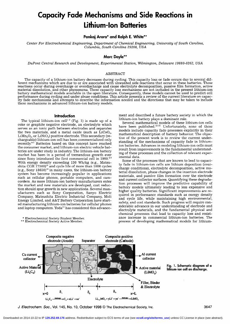
lnfroductionThe typical lithium-ion cell'-3 (Fig. 1) is made up of a
coke or graphite negative electrode, an electrolyte whichserves as an ionic path between electrodes and separatesthe two materials, and a metal oxide (such as LiCoO2,LiMn2O4, or LiNiO2) positive electrode. This secondary (re-chargeable) lithium-ion cell has been commercialized onlyrecently.47 Batteries based on this concept have reachedthe consumer market, and lithium-ion electric vehicle bat-teries are under study in industry. The lithium-ion batterymarket has been in a period of tremendous growth eversince Sony introduced the first commercial cell in 1990.89With energy density exceeding 130 Wh/kg (e.g., Matsu-shita CGR 17500)'° and cycle life of more than 1000 cycles(e.g., Sony 18650)19 in many cases, the lithium-ion batterysystem has become increasingly popular in applicationssuch as cellular phones, portable computers, and cam-corders. As more lithium-ion battery manufacturers enterthe market and new materials are developed, cost reduc-tion should spur growth in new applications. Several man-ufacturers such as Sony Corporation, Sanyo ElectricCompany, Matsushita Electric Industrial Company, MoliEnergy Limited, and A&T Battery Corporation have start-ed manufacturing lithium-ion batteries for cellular phonesand laptop computers. Yoda1' has considered this advance-
* Electrochemical Society Student Member.* * Electrochemical Society Active Member.
ment and described a future battery society in which thelithium-ion battery plays a dominant role.
Several mathematical models of these lithium-ion cellshave been published. 12-35 Unfortunately, none of thesemodels include capacity fade processes explicitly in theirmathematical description of battery behavior. The objec-tive of the present work is to review the current under-standing of the mechanisms of capacity fade in lithium-ion batteries. Advances in modeling lithium-ion cells mustresult from improvements in the fundamental understand-ing of these processes and the collection of relevant exper-imental data.
Some of the processes that are known to lead to capaci-ty fade in lithium-ion cells are lithium deposition (over-charge conditions), electrolyte decomposition, active ma-terial dissolution, phase changes in the insertion electrodematerials, and passive film formation over the electrodeand current collector surfaces. Quantifying these degrada-tion processes will improve the predictive capability ofbattery models ultimately leading to less expensive andhigher quality batteries. Significant improvements are re-quired in performance standards such as energy densityand cycle life, while maintaining high environmental,safety, and cost standards. Such progress will require con-siderable advances in our understanding of electrode andelectrolyte materials, and the fundamental physical andchemical processes that lead to capacity loss and resist-ance increase in commercial lithium-ion batteries. Theprocess of developing mathematical models for lithium-
Cu currentcollector
Active Material
(LiC6)
_÷Al currentcollector
Active material
(L1MOJ
Filler, Binder& Electrolyte
Fig. 1. Schematic diagram of alithium-ion cell on discharge.
J. Electrochem. Soc., Vol. 145, No. 10, October 1998 The Electrochemical Society, Inc. 3647
Composite negative Composite positiveelectrode (Anode) Separator electrode (Cathode)
1*
Electrolyte
x=O x=Ldathn. c,+xLr+x& Li,,MO + yLi' + y& S&. LIMO
) unless CC License in place (see abstract). ecsdl.org/site/terms_use address. Redistribution subject to ECS terms of use (see 129.252.69.176Downloaded on 2014-10-22 to IP
3648 J. Electrochem. Soc., VoL 145, No. 10, October 1998 The Eiectrochemicai Society, inc.
ion cells that contain these capacity fade processes notonly provides a tool for battery design but also provides ameans of understanding better how those processes occur.
Present Lithium-Ion Battery ModelsThe development of a detailed mathematical model is
important to the design and optimization of lithium sec-ondary cells and critical in their scale-up. West et al.""developed a pseudo two-dimensional model of a singleporous insertion electrode accounting for transport in thesolution phase for a binary electrolyte with constant phys-ical properties and diffusion of lithium ions into the cylin-drical electrode particles. The insertion process was as-sumed to be diffusion limited, and hence charge-transferresistance at the interface between electrolyte and activematerial was neglected. Later Mao and White developed asimilar model with the addition of a separator adjacent tothe porous insertion electrode.'6 These models cover only asingle porous electrode; thus, they do not have the advan-tages of a full-cell-sandwich model for the treatment ofcomplex, interacting phenomena between the cell layers.These models confine themselves to treating insertion intoTiS. with the kinetics for the insertion process assumed tobe infinitely fast. Spotnitz et al.'7 accounted for electrodekinetics in their model for discharge of the TiS, intercala-tion cathode.
The galvanostatic charge and discharge of a lithiummetal/solid polymer separator/insertion positive electrodecell was modeled using concentrated-solution theory byDoyle et al.""° The model is general enough to include awide range of separator materials, lithium salts, and com-posite insertion electrodes. Concentrated-solution theoryis used to describe the transport processes, as it has beenconcluded that ion pairing and ion association are veryimportant in solid polymer electrolytes."' This approachalso provides advantages over dilute solution theory toaccount for volume changes. Butler-Volmer-type kineticexpressions were used in this model to account for thekinetics of the charge-transfer processes at each electrode.The positive electrode insertion process was describedusing Pick's law with a constant lithium diffusion coeffi-cient in the active material. The volume changes in thesystem and film formation at the lithium/polymer inter-face were neglected and a very simplistic case of constantelectrode film resistances was considered. Long-term deg-radation of the cell due to irreversible reactions (side reac-tions) or loss of interfacial contact is not predictable usingthis model.
Fuller et al.'9" developed a general model for lithium-ion insertion cells that can be applied to any pair of lithi-um-ion insertion electrodes and any binary electrolyte sys-tem given the requisite physical property data. Fulleret al's work demonstrated the importance of knowing thedependence of the open-circuit potential on the state ofcharge for the insertion materials used in lithium-ion cells.The slopes of these curves control the current distributioninside the porous electrodes, with more sloped open-cir-cuit potential functions leading to more uniform currentdistributions and hence better utilization of active mater-ial. Optimization studies were carried out for the Beilcoreplastic lithium-ion system.37'3" The model was also used topredict the effects of relaxation time"39 on multLplecharge-discharge cycles and on peak power.
Doyle et al.'2 modified the dual lithium-ion model to in-clude film resistances on both electrodes and made directcomparisons with experimental cell data for theLiC6ILiPF6, ethylene carbonate/dimethyl carbonate (EC/DMC), Kynar FLEX®ILi9Mn,O, system. Comparisons be-tween data and the numerical simulations suggested thatthere is additional resistance present in the system not pre-dicted by present models. The discharge performance of thecells was described satisfactorily by including either a filmresistance on the electrode particles or by contact resis-tances between the cell layers or current-collector inter-faces. One emphasis of this work was in the use of the bat-
tery model for the design and optimization of the cell forparticular applications using simulated Ragone plots.
Thermal modeling is very important for lithium batteriesbecause heat produced during discharge may cause eitherirreversible side reactions or melting of metallic lithium,Chen and Evans carried out a thermal analysts of lithium-ion batteries during charge-discharge and thermal run-away using an energy balance and a simplified descriptionof the electrochemical behavior of the system."" Theiranalysis of heat transport and the existence of highly local-ized heat sources due to battery abuse indicated that local-ized heating may raise the battery temperature very quick-ly to the thermal runaway onset temperature, above whichit may keep increasing rapidly due to exothermic side reac-tions triggered at high temperature. Pals and Newmandeveloped a model to predict the thermal behavior of lithi-um metal-solid polymer electrolyte cells and cell stacks.28'2"This model coupled an integrated energy balance to a full-cell-sandwich model of the electrochemical behavior of thecells. Both of these models emphasized the importance ofconsiderations of heat removal and thermal control in lithi-um-polymer battery systems.
Verbrugge and Koch developed a mathematical modelfor lithium intercalation processes associated with a cylin-drical carbon microfiber."" They characterized and mod-eled the lithium intercalation process in single-fiber car-bon microelectrodes including transport processes in bothphases and the kinetics of charge transfer at the interface.The primary purpose of the model was to predict the poten-tial as a function of fractional occupancy of intercalatedlithium. The overcharge protection for a Li/TiS, cell usingredox additives has been theoretically analyzed in terms ofa finite linear diffusion model by Narayanan et al."
Darling and Newman modeled a porous intercalationcathode with two characteristic particle sizes." They re-ported that electrodes with a particle size distributionshow modestly inferior capacity-rate behavior and relax-ation on open circuit is substantially faster when the par-ticles are uniformly sized. Nagarajan et al.'4 modeled theeffect of particle size distribution on the intercalationelectrode behavior during discharge based on packing the-ory.1" They observed that during pulse discharge, an elec-trode consisting of a binary mixture displays higher dis-charge capacity than an electrode consisting of single-sized particles. The current from the smaller particlesreverses direction during the rest period which cannot beobserved in the case of an electrode comprised of thesame-sized particles. Recently Darling and Newman"made a first attempt to model side reactions in lithiumbatteries by incorporating a solvent oxidation side reac-tion into a lithium-ion battery model, Even though a sim-plified treatment of the oxidation reaction was used, theirmodel was able to make several interesting conclusionsabout self-discharge processes in these cells and their im-pact on positive electrode state-of-charge.
A number of models having varying degrees of sophisti-cation have been developed for lithium rechargeable bat-teries. For the most part, these models consider the idealbehavior of the systems, neglecting the phenomena thatlead to losses in capacity and rate capability during re-peated charge-discharge cycles. Fundamental models ofthese latter phenomena are less common because theseprocesses are not as well understood. Also, models of fail-ure modes in batteries do net usually have general applic-ability to a wide range of systems. However, the importanceof these phenomena in the safe and efficient operation ofhigh-energy lithium-ion batteries requires that they beincorporated into future battery models.
Capacily Fading PhenomenonSide reactions and degradation processes in lithium-ion
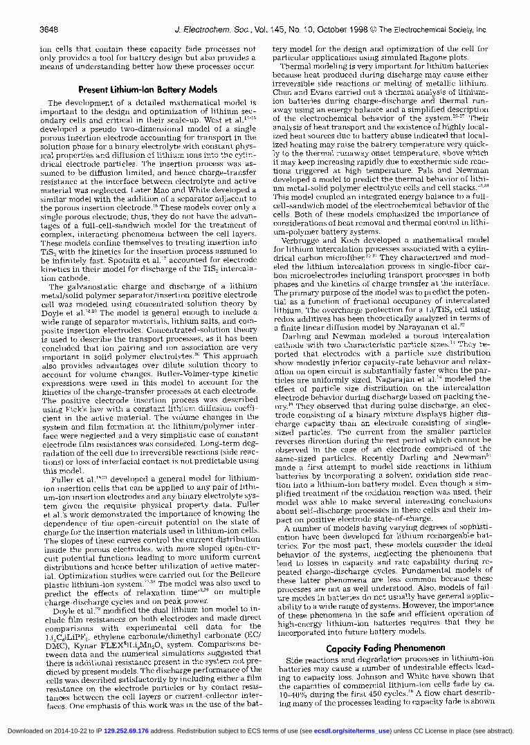
batteries may cause a number of undesirable effects lead-ing to capacity loss. Johnson and White have shown thatthe capacities of commercial lithium-ion cells fade by ca.10-40% during the first 450 cycles."' A flow chart describ-ing many of the processes leading to capacity fade is shown
) unless CC License in place (see abstract). ecsdl.org/site/terms_use address. Redistribution subject to ECS terms of use (see 129.252.69.176Downloaded on 2014-10-22 to IP
J. Electrochem. Soc., Vol. 145, No. 10, October 1998 The Electrochemical Society, Inc. 3649
LU
5.2)
oo
in Fig. 2. In Fig. 3, the capacity fade processes are shown onhalf-cell discharge curves. This gives a clearer picture ofthe processes by demonstrating where each is expected tomanifest itself during operation of the battery Below, wediscuss each of these processes in some detail, after firstdiscussing the general topic of capacity balance.
Capacily Balancing in Lithium-Ion CellsLithium-ion cells operate by cycling lithium ions be-
tween two insertion electrode hosts having different inser-tion energies. For optimum performance, the ratio of thelithium-ion capacities of the two host materials should bebalanced. Capacity balancing refers to the optimization ofthe mass loading in the two electrodes to achieve the max-imum capacity (or energy) from the battery under condi-tions of steady cycling. Due to the practical importance ofthis subject for maximizing cell performance, as well asthe safety implications with poorly balanced cells, thissubject has been discussed in the literature by severalauthors.2'22'37'35
The condition for balanced capacities in a lithium-ioncell can be written in terms of a ratio -y of active masses inthe electrodes. Written as a ratio of positive to negativeelectrode masses, this expression is2°
= = ______ = [1]sn S€p AyC÷
This equation says that the desired mass ratio depends onthe relative coulombic capacities of the two electrodes (Cis in units of mAh/g) and the amount of cyclable lithium ineach. The cyclable lithium is quantified in terms of therange of lithium stoichiometry in the insertion electrodethat can be cycled reversibly with the notation that Axrefers to the range of negative electrode stoichiometry andAy to the positive electrode. For some insertion materials,which have several plateaus over which lithium can be in-serted and deinserted, one may choose to cycle over only alimited range of stoichiometry for reversibility or safetyreasons. In these cases, the stoichiometric range entered inthe above formula would be reduced from its maximumvalue.
L Capacity JyJ
For example, consider the case of a lithium-ion cell hav-ing a petroleum coke negative electrode and a lithiummanganese oxide spinel positive electrode. By choice, wecan assign useful ranges of stoichiometries for the twoelectrode materials of 0.61 for the coke and 0.83 for thelithium manganese oxide. These stoichiometric rangescorrespond to the following electrochemical processes
chargeC, + 0.61Li + 0.61e Li061C5 [2]
discharge
chargeLiMn2O4 0.83Li + 0.83e + Li0 17Mn2O4 [3]
discharge
The active mass ratio needed to cycle these two materialsin the manner shown here is equal to 1.85. This is calcu-lated by using the theoretical capacities of both positiveand negative electrode (C÷ = 148 mAh/g and C =372 mAh/g), equal to F divided by the molecular weight ofthe electrode material in its discharged state.
The situation above describes an "ideal" lithium-ion cellin which the capacity balance does not change over the lifeof the cell. For an ideal cell, the initial lithium capacityavailable for cycling is constant over the life of the batteryUnfortunately the true case in actual lithium-ion batteriesis more complicated than this, and side reactions and sec-ondary processes are able to perturb the capacity balancefrom its ideal state. The actual optimized active mass ratiois ca. 2.05-2.15 for the coke/LiMn2O4 system, which corre-sponds to 14% excess capacity in the positive electrode.41This excess capacity is a measure of the amount of lithiumneeded to form a stable film over the electrode surfaces. Amajor process that affects the capacity balance is the initialformation period needed to passivate carbon-based elec-trodes. It is now well known that carbonaceous lithium in-sertion electrodes have irreversible capacity associatedwith the initial charging cycles.4246 This irreversible capac-ity loss is thought to result in the formation of a lithiumconducting solid electrolyte interface (SEI) layer on thesurface of the carbon, while in the process consuming someportion of the cyclable lithium ions in the cell. The loss ofcyclable lithium to create this passivation layer has a pro-found impact on the capacity balance in the cell because itcan remove a significant portion of the cyclable lithiumdepending on the type of carbon used.
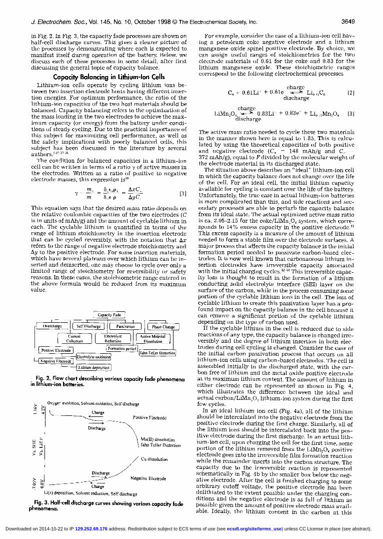
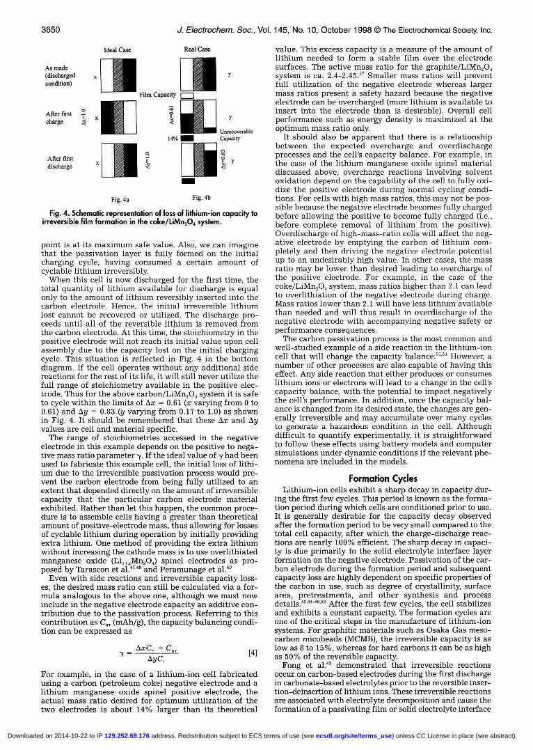
If the cyclable lithium in the cell is reduced due to sidereactions of any type, the capacity balance is changed irre-versibly and the degree of lithium insertion in both elec-trodes during cell cycling is changed. Consider the case ofthe initial carbon passivation process that occurs on alllithium-ion cells using carbon-based electrodes. The cell isassembled initially in the discharged state, with the car-bon free of lithium and the metal oxide positive electrodeat its maximum lithium content. The amount of lithium ineither electrode can be represented as shown in Fig. 4,which illustrates the difference between the ideal andactual carbon/LiMn9O4 lithium-ion system during the firstfew cycles.
In an ideal lithium-ion cell (Fig. 4a), all of the lithiumshould be intercalated into the negative electrode from thepositive electrode during the first charge. Similarly all ofthe lithium ions should be intercalated back into the pos-itive electrode during the first discharge. In an actual lith-ium-ion cell, upon charging the cell for the first time, someportion of the lithium removed from the LiMn2O4 positiveelectrode goes into the irreversible film formation reactionwhile the remainder inserts into the carbon structure. Thecapacity due to the irreversible reaction is representedschematically in Fig. 4b by the smaller box below the neg-ative electrode. After the cell is finished charging to somearbitrary cutoff voltage, the positive electrode has beendelithiated to the extent possible under the charging con-ditions and the negative electrode is as full of lithium aspossible given the amount of positive electrode mass avail-able. Ideally the lithium content in the carbon at this
____________________________________ I I —— I
Current 1 [ miectrolydfl I Active Materiiifl I
L_ceiiectors I L Reduction J
huege
LifDisch] [}'assivasioo1 c]'4!'osite EleIITITE0fh5tb0n1 penod] ftypp-'reiier oisiin
Negative Eie1 ___________________Lithium depositioej
Fig. 2. Flow chart describing various capacity fade phenomenain lithium-ion baiteries.
Oxyger evolution, Solvent oxidution, Self discharge'° >1
churgesitive Electrode
rhargeMn(lI) dissolutionJahn Teller nistoeion
Cu dissolution
schurseNegative Electrode
Charge
Li(s) deposttion, Solvent reduction, Self discharge
Fig. 3. Half-cell discharge curves showing various capacity fadephenomena.
) unless CC License in place (see abstract). ecsdl.org/site/terms_use address. Redistribution subject to ECS terms of use (see 129.252.69.176Downloaded on 2014-10-22 to IP
003U j. tiecrrocnem. oc., vol. i 'in, ['JO. 1 U, ucxooer 1 *3b w I ne tiectrocnemicai tiociety, inc.
Fig. 4a Fig. 4b
Fig. 4. Schematic representation of loss of lithium-ion capacity toirreversible film formation in the coke/LiMn2O4 system.
point is at its maximum safe value. Also, we can imaginethat the passivation layer is fully formed on the initialcharging cycle, having consumed a certain amount ofcyclable lithium irreversibly.
When this cell is now discharged for the first time, thetotal quantity of lithium available for discharge is equalonly to the amount of lithium reversibly inserted into thecarbon electrode. Hence, the initial irreversible lithiumlost cannot be recovered or utilized. The discharge pro-ceeds until all of the reversible lithium is removed fromthe carbon electrode. At this time, the stoichiometry in thepositive electrode will not reach its initial value upon cellassembly due to the capacity lost on the initial chargingcycle. This situation is reflected in Fig. 4 in the bottomdiagram. If the cell operates without any additional sidereactions for the rest of its life, it will still never utilize thefull range of stoichiometry available in the positive elec-trode. Thus for the above carbon/LiMn2O4 system it is safeto cycle within the limits of Ax = 0.61 (x varying from 0 to0.61) and Ay = 0.83 (y varying from 0.17 to 1.0) as shownin Fig. 4. It should be remembered that these Ax and Ayvalues are cell and material specific.
The range of stoichiometries accessed in the negativeelectrode in this example depends on the positive to nega-tive mass ratio parameter -y. If the ideal value of y had beenused to fabricate this example cell, the initial loss of lithi-um due to the irreversible passivation process would pre-vent the carbon electrode from being fully utilized to anextent that depended directly on the amount of irreversiblecapacity that the particular carbon electrode materialexhibited. Rather than let this happen, the common proce-dure is to assemble cells having a greater than theoreticalamount of positive-electrode mass, thus allowing for lossesof cyclable lithium during operation by initially providingextra lithium. One method of providing the extra lithiumwithout increasing the cathode mass is to use overlithiatedmanganese oxide (Li,+Mn2O4) spinel electrodes as pro-posed by Tarascon et al.47'48 and Peramunage et al.49
Even with side reactions and irreversible capacity loss-es, the desired mass ratio can still be calculated via a for-mula analogous to the above one, although we must nowinclude in the negative electrode capacity an additive con-tribution due to the passivation process. Referring to thiscontribution as C1.. (mAh/g), the capacity balancing condi-tion can be expressed as
AxC + CAyC4
For example, in the case of a lithium-ion cell fabricatedusing a carbon (petroleum coke) negative electrode and alithium manganese oxide spinel positive electrode, theactual mass ratio desired for optimum utilization of thetwo electrodes is about 14% larger than its theoretical
value. This excess capacity is a measure of the amount oflithium needed to form a stable film over the electrodesurfaces. The active mass ratio for the graphite/LiMn,04system is ca. 2.4-2.45. Smaller mass ratios will preventfull utilization of the negative electrode whereas largermass ratios present a safety hazard because the negativeelectrode can be overcharged (more lithium is available toinsert into the electrode than is desirable). Overall cellperformance such as energy density is maximized at theoptimum mass ratio only.
It should also be apparent that there is a relationshipbetween the expected overcharge and overdischargeprocesses and the cell's capacity balance. For example, inthe case of the lithium manganese oxide spinel materialdiscussed above, overcharge reactions involving solventoxidation depend on the capability of the cell to fully oxi-dize the positive electrode during normal cycling condi-tions. For cells with high mass ratios, this may not be pos-sible because the negative electrode becomes fully chargedbefore allowing the positive to become fully charged (i.e.,before complete removal of lithium from the positive).Overdischarge of high-mass-ratio cells will affect the neg-ative electrode by emptying the carbon of lithium com-pletely and then driving the negative electrode potentialup to an undesirably high value. In other cases, the massratio may be lower than desired leading to overcharge ofthe positive electrode. For example, in the case of thecoke/LiMn2O4 system, mass ratios higher than 2.1 can leadto overlithiation of the negative electrode during charge.Mass ratios lower than 2.1 will have less lithium availablethan needed and will thus result in overdischarge of thenegative electrode with accompanying negative safety orperformance consequences.
The carbon passivation process is the most common andwell-studied example of a side reaction in the lithium-ioncell that will change the capacity balance.50'5' However, anumber of other processes are also capable of having thiseffect. Any side reaction that either produces or consumeslithium ions or electrons will lead to a change in the cell'scapacity balance, with the potential to impact negativelythe cell's performance. In addition, once the capacity bal-ance is changed from its desired state, the changes are gen-erally irreversible and may accumulate over many cyclesto generate a hazardous condition in the cell. Althoughdifficult to quantify experimentally, it is straightforwardto follow these effects using battery models and computersimulations under dynamic conditions if the relevant phe-nomena are included in the models.
Formation CyclesLithium-ion cells exhibit a sharp decay in capacity dur-
ing the first few cycles. This period is known as the forma-tion period during which cells are conditioned prior to use.It is generally desirable for the capacity decay observedafter the formation period to be very small compared to thetotal cell capacity, after which the charge-discharge reac-tions are nearly 100% efficient. The sharp decay in capaci-ty is due primarily to the solid electrolyte interface layerformation on the negative electrode. Passivation of the car-bon electrode during the formation period and subsequentcapacity loss are highly dependent on specific properties ofthe carbon in use, such as degree of crystallinity, surfacearea, pretreatments, and other synthesis and processdetails.42'4440'52 After the first few cycles, the cell stabilizesand exhibits a constant capacity. The formation cycles areone of the critical steps in the manufacture of lithium-ionsystems. For graphitic materials such as Osaka Gas meso-carbon micobeads (MCMB), the irreversible capacity is as
141low as 8 to 15%, whereas for hard carbons it can be as highas 50% of the reversible capacity.
Fong et al.42 demonstrated that irreversible reactionsoccur on carbon-based electrodes during the first dischargein carbonate-based electrolytes prior to the reversible inser-tion-deinsertion of lithium ions. These irreversible reactionsare associated with electrolyte decomposition and cause theformation of a passivating film or solid electrolyte interface
Ideal Case Real Case
Aa made
(dischargedcondition)
After firstcharge
After firstdischarge
Film Capacity
14%unncovenwe
________ capacity
q
) unless CC License in place (see abstract). ecsdl.org/site/terms_use address. Redistribution subject to ECS terms of use (see 129.252.69.176Downloaded on 2014-10-22 to IP
J. Electrochem. Soc., Vol. 145, No. 10, October 1998 The Electrochemical Society, Inc. 3651
on the surface of the carbon. When all the available surfacearea is coated with a film of decomposition products, fur-ther reaction stops. In subsequent cycles, these cells exhib-it excellent reversibility and can be cycled without capaci-ty loss for many cycles. These authors first showed that thereversible insertion of lithium into graphitic carbons waspossible as long as the proper passivating solvent was pre-sent. Gas evolution was observed by Gozdz et al.53 duringthe formation of the passivation layer on the carbon elec-trode during the first charge of a lithium-ion cell. The gasevolved correlated well with the irreversible capacity lossobserved during the formation cycle. More details of carbonpassivatio:n in various solvent systems and the mechanismsof the passivation process are reviewed in later sections onelectrolyte reduction and film formation.
The formation period is critical in lithium-ion batterymanufacture because of its economic impact. First, it obli-gates manufacturers to invest in battery cycling stations tocycle cells several times before sending them to market,consuming both time and resources. Second, irreversiblecapacity consumed during the formation period is lost tothe battery, directly subtracting from the system's energy.Last, the formation period generates gases which undersome conditions may need to be vented prior to furtheroperation of the cell. Research efforts worldwide continueto generate very high capacity carbon electrode materialshaving high irreversible capacities. To utilize these materi-als in the most efficient manner requires a prepassivationor prelithiation scheme not involving the sacrifice of a sub-stantial quantity of the cyclable lithium available in thepositive electrode. Although several research groups havebeen studying these processes and potential alternative ap-proaches, there is no known solution for eliminating theformation period in an economically feasible manner.
Overcharge PhenomenaUnder conditions of overcharge, major capacity losses
have been observed in all types of lithium-ion cells. Thepoor overcharge resistance of commercial lithium-ion cellsand the safety issues that result from overcharge have ledto tight co:ntrol over charging and discharging of commer-cial cells using built-in electronic circuitry. The future ap-plication cf lithium-ion cells in new areas would be facil-itated by advances in understanding and controllingovercharge. In particular the use of lithium-ion cells inmulticell bipolar stacks requires a greater degree of over-charge tolerance due to the difficulty in achieving uniformutilization of all cells in series stacks.
Overcharge losses can be classified into three main typesat present: (i) overcharge of coke and graphite-based neg-ative electrodes, (ii) overcharge reactions for high-voltagepositive electrodes, and (iii) overcharge/high-voltage elec-trolyte oxidation processes. These side reactions lead toloss of the active material and consumption of electrolyte,both of which can lead to capacity loss in the cell.
Overcharge of Coke and Graphite-BasedNegative Electrodes
During overcharge of lithium-ion cells, metallic lithiummay be deposited on the negative electrode surface as theprimary side reaction. This reaction is expected for cellswith excess cyclable lithium due to either higher than de-sired initial mass ratio or lower than expected lithiumlosses during the formation period. The freshly depositedlithium covers the active surface area of the negative elec-trode leading to a loss of the cyclable lithium and con-sumption of electrolyte because of the highly reactivenature of metallic lithium. This phenomenon may occur athigh charge rates even for cells with the correct mass ratiobecause of the polarization at the negative electrode underthese conditions.22 However, the more common circum-stance leading to lithium deposition is poorly balancedcells having too much positive electrode mass initially. Theprimary side reaction involved in the overcharge process is
Li + e — Li(s)
Li2<0 2NiO2 —* LiNi,04 + 02(g)
X - Mn02 -Mn2O3
+O2(g)
and the intercalation-deintercalation reaction on the neg-ative electrode (coke or graphite) may be written
chargeC6 + xLi + xe Li1C, [6]
dischargeLithium metal deposited on the negative electrode reacts
quickly with the solvent or salt molecules in the vicinitygiving Li2CO3, LiF, or other products.4251 The lithium metalis expected to form near the electrode-separator boundarywhere the electrode potential is more negative. The prod-ucts formed may block the pores, leading to a loss of ratecapability as well as capacity losses. Formation of lithiummetal is also a safety hazard due to its extreme reactivitywith the liquid solvents. Lithium metal deposition may bemore of a concern with graphitic carbon electrodes thanwith coke electrodes due to the lower average open-circuitpotential of the former. For this reason, mass ratios in cellsusing graphite are usually chosen to be smaller thanthe optimum in order to provide a buffer against lithiumdeposition, with the negative consequence that the full372 mAh/g capacity of the graphite is not attained.
Overcharge Reactions for High-VoltagePositive Electrodes
Overcharging the positive electrodes in lithium-ion cellscan lead to a wide variety of electrochemical reactionsdepending on the details of the system chemistry. As withthe negative electrode, the extent to which overcharging isexpected at the positive electrode depends on the system'scapacity balance. For cells with too low a mass ratio, thepositive electrode is stressed to a greater extent duringcharging and overcharge becomes a possibility. Over-charging the positive electrode can lead to capacity lossdue to inert material formation (e.g., Co304) or solvent oxi-dation due to the high positive electrode potential. Forma-tion of electrochemically inactive electrode decompositionproducts leads to a capacity imbalance between the elec-trodes. Thermal abuse of the positive electrode can lead tooxygen loss from the metal oxide lattice. This oxygen canincrease the pressure inside the cell and represents apotential safety concern.
Dahn et al.52 proposed the following decompositionreactions for the three main positive electrode materials intheir charged states under abuse conditions. The reactionproposed for LiCoO2 can be expressed as
Li5CoO9(1
[Co204 + 02(g)] + yLiCoO2,
where y c 0.4 [7]for LiNiO, 22
[8]
and for y-MnO., 22 as
[9]
They observed that X-Mn02 is more tolerant toward elec-trical and thermal abuse than Li5NiO, and Li4CoO2. Oxy-gen loss from the metal oxides was observed when p < 1 andincreased with decreasing stoichiometry. This loss of oxy-gen began at 200°C for Li0 3NiO2, 240°C for Li2 4CoO2, andabout 385°C for X-Mn02, when heated at a rate of 1°C/mm.The higher the heating rate, the higher is the 02 onset tem-perature and vice versa. Formation of oxygen in the sealedcell in the absence of any recombination mechanism (asexists in Ni-Cd, Pb-acid, and Ni-MH cells using aqueouselectrolytes) is a safety concern because of the accumula-tion of flammable gas mixtures in the cell. Also, the finalmetal oxide products such as Co204, LiNi9O4, and Mn202are inert to lithium insertion-deinsertion, and hence capac-ity is lost irreversibly
Staniewicz22 proposed an overcharge mechanism for[5] their LiNiO2 electrodes by accounting for all the lithium
) unless CC License in place (see abstract). ecsdl.org/site/terms_use address. Redistribution subject to ECS terms of use (see 129.252.69.176Downloaded on 2014-10-22 to IP
3652 J. Electrochem. Soc., Vol. 145, No. 10, October 1998 The Electrochemical Society, Inc.
Phase L—Lithium ions used to passivate carbon irre-versibly and/or not able to cycle back into the LiNiO2
LiNiO, —* 0.15Li + Li0 ,,Ni00 + 0.15e
Phase 11.—Reversible cycling
Li0 ,5NiO,, —' 0.5Li + Li0 35NiO2 + 0.5e
Phase 111.—Overcharge
Li0 35NiO, —* 0.35Li + Ni02 + O.35e
The first phase accounts for the lithium ions used to formthe passive film, the second phase for reversible cycling,and the third phase accounts for the lithium ions removedduring overcharge. The overcharge reaction proposed byStaniewicz" does not agree with the mechanism proposedby Dahn et al.52 for Li,NiO2 electrodes under conditions ofthermal abuse. Moreover, NiO9 is not usually thought to bestable due to the Ni(IV) oxidation state.56 No experimentaldata were provided by the author to support the abovehypotheses.
The formation of low lithium content Li,NiO2 (y .c 0.2)has been stated as a cause of cell failure during cycling.'1In addition, the material becomes highly catalytic towardelectrolyte oxidation, and some of the nickel ions maymigrate to lithium sites. The first cycle irreversibility isprimarily related to the amount of Ni" between the slabsof NiO,, which requires extra charge for oxidation to ahigher valence state. The stability of the structure ofLiNiO, at low lithium content can be improved by substi-tuting Ni with Al or B.'7
Recently, the thermal stability of LINiO, cathodes hasbeen studied in detail by substituting a portion of the Nior Li with other elements (Co, Mn, Mg, Ca, Sr, Ba)."" Thesubstitution of Ni with Co improves the cycling behaviorat room temperature, but the cycling characteristics athigh temperatures remain unsatisfactory.60'6' Substitutinga part of the Ni in LiNiO, with alkaline earth metals (Mg,Ca, Sr, Ba) and with Al improves the high-temperatureand high-rate performance of these electrodes.5' At hightemperatures, the deterioration in the performance duringcharging and discharging is greatly influenced by a changein the chemical reactivity of the active material. In thepresence of other substituents in the crystal structure, thereactivity decreases during deep charging and dischargingand at high temperatures, which leads to a more stablematerial. In the case of LiCoO,, the high-temperature per-formance is deteriorated by the introduction of other ele-ments. When the Ni in LiNiO., is substituted with Ca, Nb,or In, the structural changes observed during the chargingprocess are very small, which leads to better cyclability ofthese doped materials."
The thermal stability of lithium manganese oxide spinelphases was studied by Thackeray et al.'2 They proposedthat Li,MnO, is formed and oxygen is evolved when thespinel is heated in the temperature range of 780 to 915°C.The rate of oxygen evolution increased above 915°C, andaround 1200°C, both 02 and Li,O were lost. The abovereactions are not electrochemical reactions and occurwhen the active material is heated to a particular temper-ature. Including thermally induced electrode decomposi-tion reactions in a phenomenological battery model maynot be necessary because battery failure will likely haveoccurred already at lower temperatures.
Gao and Dahn showed a correlation between the capac-ity fade of the spinel and the growth of the 3.3 V dischargeplateau upon cycling.'3 The 3.3 V discharge plateau in-creased each time the cell was charged to a higher voltage,suggesting that LiMn,04 tends to lose 02 when over-charged. The following mechanism was proposed
El —' (Oxid El) + e
LiMn2O4 + 28e —* LiMn2O4_, + 802_ [14]
where El is the electrolyte solvent molecule and (oxid El)denotes a positively charged electrolyte solvent molecule(radical cation). The radical cation (oxid El) can be as-sumed to be very unstable and will participate in furtherside reactions immediately upon formation. One possibleprocess would be dimerization of the radical with accom-panying expulsion of two protons. If this cationic speciesis sufficiently stable to reach the negative electrode, itwould undergo reduction either back to the original sol-vent species or to other products. Highly delocalized salt
[12] anions such as PF may help to stabilize cationic speciessuch as these.
These authors state that the electrolyte may act as anelectron donor to the partially delithiated spinel, inducingthe oxygen loss from the oxide structure. It is possible thata second phase (similar to what is formed during heating)with the rock-salt structure forms at the surface ofLiMn,0, when it loses oxygen over the course of cycling.The loss of oxygen from the sample during cycling is unde-sirable, not only because it could induce structural dam-age to the sample surface impacting the cycling ability, butalso because it tends to oxidize the electrolyte which alsoreduces the cell's life.
Overcharge/High Voltage ElectrolyteOxidation Processes
The electrolytes used in lithium-ion cells are mixtures oforganic solvents and one or more lithium salts. The mostpopular electrolytes currently being used include mixturesof the linear and cyclic carbonates such as propylene car-bonate (PC), ethylene carbonate (EC), dimethyl carbonate(DMC), diethyl carbonate (DEC), and ethyl methyl car-bonate (EMC) and salts such as LiPF6, LiBF4, LiAsF,, andLiC1O4. Sony reportedly uses a mixture of PC, DMC, andEMC with LiPF, salt, whereas Sanyo and Matsushita usemixtures of EC, DMC, and DEC and EC, DMC, DEC, andEMC, respectively, with LiPF,
High voltage positive electrodes used in lithium-ion bat-teries present a stringent requirement for electrolyte sta-bility and purity. The electrolyte choice is a limiting factorin lithium-ion batteries because the maximum voltage ofthe cell is limited by the decomposition potential of theelectrolyte. Common electrolytes in use today decomposeat high voltages (>4.5 V) forming insoluble products(Li,C05, etc.)42'4 which block the pores of the electrodesand cause gas generation in the cell. These effects cancause both capacity loss upon further cycling of the celland can also be an extreme safety hazard. One particularsolvent combination, EC/DMC, is in use in many systemsalone and in combination with other solvents and isclaimed to have the highest oxidation resistance amongthe common carbonate mixtures.'4 Campbell et al.'5 re-ported that the oxidation potential of pure PC is higherthan that of PC containing electrolyte salts. This suggeststhat the electrochemical oxidation of nonaqueous elec-trolytes is enhanced by the presence of electrolyte salts.
Decomposition potentials are assessed experimentallyby performing cyclic voltammetry either on inert metalsurfaces or on actual insertion electrode materials and set-ting an arbitrary criterion on the current density abovewhich solvent breakdown is assumed to be occurring. Forirreversible electrochemical side reactions such as these,no thermodynamic open-circuit potential exists, andhence the decomposition potential does not have a firmmeaning. Instead, these side reactions may often be de-scribed with Tafel equations which lead to a finite rate ofdecomposition at all voltages, increasing exponentiallywith increasing voltage.3'
The decomposition potentials of many electrolytes arereported in Table I; however, it is not always clear whetherthe solvent or the salt or both are involved in the oxidation
[13] processes.'4"" In addition, the ambiguity in reporting
ions in LiNiO,-based cells. They divided the cycling pro- andcess for the LiNiO2 electrode into three phases.
[101
[11]
) unless CC License in place (see abstract). ecsdl.org/site/terms_use address. Redistribution subject to ECS terms of use (see 129.252.69.176Downloaded on 2014-10-22 to IP
J. Electrochem. Soc., Vol. 145, No. 10, October 1998 The Electrochemical Society, Inc. 3653
values for solvent oxidation potentials is not always ap-preciated. These data are only well defined if the value ofthe current density at which the decomposition potentialis assessed is given as well as the voltage scan rate and theelectrode material used. We have taken the cyclic volt-ammetry data of Kanamura et al.'6 measured at a sweeprate of 50 mV/s and used the criterion of 0.1 mA/cm2 as thethreshold current density to define the oxidation poten-tials given in Table I. Data of Tarascon et al.64 were used asgiven in their paper because the actual cyclic voltamma-grams were not provided by these authors. Christie andVincent67 measured the oxidation potential using cyclicvoltammetry at a sweep rate of 200 mV/s and used the cri-terion of 1 mA/cm2. Ossolo et al.68 used linear sweepvoltammetry at a scan rate of 2 mV/s to determine the oxi-dation potential (E0) of various electrolytes on Lji+rV3OSelectrodes. They assumed E0 to be the potential at whicha current density of 0.5 mA/cm2 was recorded.
The solvent oxidation process can be stated in general asfollows
solvent — oxidized products (gases, solution, and
solid species) + ne [15]
Any solvent (for example, PC or EC) oxidized will be lost,eventually leading to an increase in the salt concentrationand a drop in the electrolyte level which will adverselyaffect the cell capacity. Also, the solvent oxidation productssuch as gases or other species will build up in the cell andcause a variety of problems. The rate of solvent oxidationdepends ort the surface area of the positive electrode mate-rial, current collectors, and the carbon black additive. Infact, the choice of carbon black and its surface area arecritical variables because solvent oxidation may occurmore on the carbon black than on the metal oxide electrodedue to the higher surface area of the former.°
If a small part of the electrolyte is consumed during eachcharge, more electrolyte needs to be used when the cell isassembled. This implies less active material for a constant-volume container and consequently less initial capacity.Also, the solid products may form passivating layers on theelectrodes that increase the polarization of the cell andthereby lower the output voltage of the battery.
Novak et al.69 found that PC oxidizes at potentials aslow as 2.1 V vs. Li/Li on Pt and that the rate of oxidationincreases substantially above 3.5 V. Depending on the elec-trode material, PC oxidation can begin at potentials as low
as 2 V vs. Li/Lit; however, a much greater degree of sta-bility (up to and exceeding 4.5 V) is often exhibited by PCin practice. Cattaneo and Ruch7° analyzed the volatilegaseous products from the decomposition of LiClO4/PCand LiAsF6/PC on heat-treated Mn02 electrodes using on-line mass spectroscopy. Bulk oxidation of the electrolytetakes place above 4.0 V vs. Li/Li. CO2 evolution was ob-served at low potentials (3.15 and 3.4 V vs. Li/Lit) depend-ing on the state of charge of the electrodes. No CO2 wasobserved in the reverse (cathodic) scan.
Chlorinated species were formed from the decomposi-tion of ClO ions above 4.5 V. ° The species identified wereC102 and HC1, which were assumed to be formed by thefollowing mechanism
ClO -* e + dO4 -+ Cl07 + 2 O4 + e
ClO + H + e - HC1 + 02(g)
2 Oad — 02(g)
[16]
[17]
[181
Eggert and Heitbaum71 also observed the oxidation of per-chlorate anions on a Pt electrode at potentials above 4.6 Vvs. Li/Lit using differential electrochemical mass spec-trometry (DEMS). The instability of Cl02 in the presenceof protons from the oxidation of PC will produce HC1.Oxygen evolution is also observed in the decomposition ofLiC1O4 electrolytes.
Christie and Vincent67 reported the oxidation potentialfor 1 M LiPF6 in PC at a Ni microelectrode. Kanamuraet al.7273 studied the ring opening of PC on Pt, Al, Au, andNi electrodes. The PC oxidation potentials on these mate-rials varied from 4.5 V for Ni to 6 V for Cu vs. Li/Lit. It wasshown by Kanamura et a].73 that the anodic behavior of Nielectrodes in various propylene carbonate electrolytes de-pends strongly on the type of electrolyte salt used. Theoccurrence of decomposition products depends on the typeof anion in the high electrode potential range. Electrolyteoxidation during overcharge of lithium-ion cells has beenverified experimentally by Tarascon et al.37 by cyclic volt-ammetry experiments. However, none of these studies pro-vided mechanisms for the decomposition processes or usedanalytical techniques to study the products formed. Con-sidering the large number of studies on solvent reduction inlithium batteries, and the relative importance of solventoxidation to cell performance and safety, the lack of fun-damental knowledge in this area is surprising.
Electrolyte
LiC1O4 + PC/DME (1:1)1 M LiC1O4 + PC1 M LiC1O4 + PC1 M LiClO4 + PC1 M LiC1O4 + PC1 M LiClO4 + EC/DEE (1:1)1 M LiC1O4 + EC/DMC (1:1)LiN(CF3SO2)2 + EC/DEE (1:1)L1N(CF3SO2), + EC/DME (1:1)LiCF3SO3 + EC/DEE (1:1)LICF3SO3 + EC/DMC (1:1)LIBF4 + EC/DEE (1:1)LiBF4 + EC/DMC (1:1)LiAsF6 + PC/DME (1:1)LIAsF6 + PCLiAsF6 + PC/DME (1:1)LiAsF6 + EC/DMC (1:1)LiAsF6 + EC/DEE (1:1)LiPF6 + EC/DEE (1:1)LiPF6 + EC/DMC (1:1)LiPF6 + PCLiPF6 + PCLIPF6 + PC/EC (Li)LiPF6 + DMCLiPF6 + DECLiPF6 + PC/DMC (1:1)LIPF6 + EC/DEC (1:1)
Table I. Electrolyte oxidation potential of various electrolytes on different substrates.
E0(Vvs. Li/Li)
4.64.55.755.25.54.55
>5.14.44.354.13.23.4
>5.14.75.64.74.73.93.8
>5.15.0
>5.1>5.1>5.13.8
>5.1>4.8
Substrate
LjV3O8NiAlPt
6866666666646464646464646468676764646464
66, 67646464646464
Ref.
AuLiMn9O4 + 10% carbon blackLiMn9O4 + 10% carbon blackLiMn3O4 + 10% carbon blackLiMn2O4 + 10% carbon blackLiMn2O4 + 10% carbon blackLiMn2O4 + 10% carbon blackLiMn2O4 + 10% carbon blackLiMn2O4 + 10% carbon black
LiV3O8PtPt
LiMn2O4 + 10% carbon blackLiMn2O4 + 10% carbon blackLiMn3O4 + 10% carbon blackLiMn2O4 + 10% carbon black
NiLiMn2O4 + 10% carbon blackLiMn2O4 + 10% carbon blackLiMn2O4 + 10% carbon blackLiMn9O4 + 10% carbon blackLiMn2O4 + 10% carbon blackLiMn3O4 + 10% carbon black
) unless CC License in place (see abstract). ecsdl.org/site/terms_use address. Redistribution subject to ECS terms of use (see 129.252.69.176Downloaded on 2014-10-22 to IP
3854 J. Electrocliem. Soc., Vol. 145, No. 10, October 1998 The Electrochemical Society, Inc.
A detailed discussion of electrolyte decomposition (re-duction) mechanisms is given in a later section.
Overcharge Protection7476Successful commercialization of lithium-ion batteries
depends very much on their safety during operation undernormal and especially under abusive conditions. An abusecondition generally leads to an increase in cell tempera-ture which can initiate self-heating of the cell and eventu-ally lead to thermal runaway.
The organic solvents commonly used to prepare elec-trolytes for lithium-ion batteries undergo irreversible oxi-dation at the positive electrode, which deleteriouslyaffects the cycling performance of lithium batteries. Acommon way to avoid this is by including an additive inthe electrolyte, an internal "chemical shuttle," to providea current bypass mechanism when the cell exceeds a cer-tain voltage.7'm The ideal chemical shuttle operates at ornear the voltage of the fully charged cell and takes up theextra charge passed during overcharge, thereby prevent-ing damaging reactions from proceeding. For typical lithi-um-ion cells, the desired potential of the redox process isapproximately 4.5 to 5.0 V vs. Li/Li or 1.5 to 1.0 V vs.HVH2. In such a case, the electrochemical reactions sus-tained during overcharge at the positive and negative elec-trodes are3277
H - 0 + ne0 + ne —°R
Species 0 is generated at the positive electrode and diffus-es to the negative electrode where it is reduced to H. Theredox couple shuttles between the two electrodes to takeup the excess charge input during overcharge and contin-ues until charging is terminated.
For example, Lil functions as a good redox additive forovercharge protection at voltages close to the charged cellpotential for certain 3 V lithium cells.78" Its use in 1 MLiPF6/THF solutions has been shown to avoid the oxida-tion of the electrolyte on Pt surfaces during overcharge. Atanodic potentials (less positive than the fully charged cellpotential), Lii undergoes a two-step process of oxidationof iodide ion to triiodide ion (3.2 V vs. Li/Li'S) and furtheroxidation of tritodide ion to iodine (3.65 V)
LiI-°L + Li'3L —* 2e
2I —* 3I + 2e
The iodine generated by the oxidation of LiT reacts chem-ically with lithium metal to regenerate Lil. The reductionof iodine occurs via a similar stepwise process of reductionof iodine to trhodide ion (3.55 V) and trilodide ion toiodide ion (2.75 V).
In addition to chemical shuttles, other methods of over-charge protection which are being used in commercialcells are
1. Separators with melting points of about 140°C canhelp in overcharge protection.8283 The purpose is to have apolymer membrane that melts and shuts off the currentwhen the cell temperature rises above a given value duringshort-circuit conditions. The cells are prevented fromreaching a high internal temperature by ceasing the reac-tions (and hence heat generation) when current is prevent-ed from flowing across the separator. A number of poly-olefin [e.g., polyethylene (130°C), and polypropylene(155°C)] based separators that can be used as internal safe-ty devices by closing down the pores during short-circuitconditions have been developed.'4 Sony uses a polypro-pylene-based separator (161.7°C mp), whereas Sanyo andMatsushita use polyethylene-based separators with melt-ing points of 135.4 and 133.4°C, respectively18 The ,shutdown temperature for Celgard® 2300 FSM is 131°C. 8
2. Additives to the cathode mix, such as Li,C03, 8 willdecompose during overcharge and increase the pressureinside the cell. This pressure activates the vent present at
the top of the cell, and the pressure is released and the cir-cuit broken. The presence of excess additives does notgreatly affect the current flow during normal operation ofthe cell, as shown in the Sony cell.82 Moli Energy89 has used2 wt % biphenyl in their graphite/LiCoO2 cells for over-charge protection. Solid biphenyl decomposition productsdeposit on the cathode resulting in high internal imped-ance and low rate capability
3. Explosion-proof valves7482 become deformed upon in-crease of internal pressure of the cell to cut a connectionlead contained in the cell. The supply of charging currentis cut off when the pressure increases abnormally
Elecfrolyte Decomposition (Reduction) ProcessesElectrolyte reduction44748649° can jeopardize the capac-
ity and cycle life of the cell by consuming salt and solventspecies, and compromises the safety of the system by gen-erating gaseous products which increase the internal pres-sure of the cell. Minimizing the electrolyte reduction reac-tions and the capacity losses related to these processes is amajor requirement for enhancing cycle life and improvingthe high-temperature performance of lithium-ion batter-ies. Electrolyte reduction is an expected feature of all cellsusing carbon-based insertion electrodes due to the insta-bility of the electrolyte to the carbon electrode under cath-odic conditions. The process of carbon passivation during
[19] the initial cell cycling is referred to as the formation peri-od as discussed earlier. Ideally, electrolyte reduction is
[20] confined to the formation period and does not continueduring the steady cycling of the cell.
Electrolyte reduction reactions on carbon surfaces aresimilar to those on lithium metal because the difference inpotential between the metallic lithium and fully lithiatedcarbon is very small.81 For this reason, a large amount ofliterature on electrolyte reduction processes on metalliclithium can be utilized to understand these processes oncarbon insertion electrodes. A large number of experimen-tal techniques including X-ray photoelectron spectroscopy(XPS), Auger electron spectroscopy energy dispersive X-ray analysis (EDAX), Haman spectroscopy on-line massspectroscopy in situ and ex situ Fourier transform in-frared (FTIR) spectroscopy atomic force microscopy(AFM), and electron spin resonance have been used todetermine the reduction mechanisms and to identify the
[21] products formed on carbon electrode surf aces.419297Dey97 studied the electrochemical decomposition of PC
[22] on graphite and proposed a decomposition mechanism[23] 2Li + 2& + (PC/EC) —' [propylene(g)/ethylene(g)]
+ Li2CO7(s) [24]
The above reaction occurs during the first discharge whenthe potential of the electrode is near 0.8 V vs. Li/Li'. Fonget al.42 proposed a similar mechanism for the irreversiblecapacity loss during the first cycle on graphitic carbonelectrodes with mixed EC/PC electrolytes.
Aurbach and coworkers914397 have performed extensivestudies of solvent and salt reduction processes and theirproducts on metallic lithium and carbon-based electrodesin a variety of electrolytes. They observed ROCO2Lispecies [probably CH3CH(OCO2Li)CH2OCO2Li] and propy-lene resulting from a one-electron reduction process of PC.Previously Dey stated that PC reduction on graphite is atwo-electron process with Li2CO3 and propylene as majorproducts. Aurbach has argued that ROCO2Li species arehighly sensitive to trace water and react rapidly with it toform Li2CO3, suggesting that previous studies were notconducted under sufficiently dry conditions.
In the presence of crown ethers,9195 carbon electrodesretain their graphitic structure and undergo reversibleintercalation because the solvent is not cointercalated andreduced within the carbon, but rather on the surface.When the reduction of PC takes place on the surface, thecharge transfer occurs mostly through existing films, andone would expect a one-electron reduction to be favorablebecause the driving force for PC reduction diminishes. In
) unless CC License in place (see abstract). ecsdl.org/site/terms_use address. Redistribution subject to ECS terms of use (see 129.252.69.176Downloaded on 2014-10-22 to IP
J. Electrochem. Soc., Vol. 145, No. 10, October 1998 The Electrochemical Society, Inc. 3655
previous studies,92 graphite electrodes were destroyed andexfoliated in the absence of crown ethers, and did notreach intercalation stages when PC was the solvent. Thus,most of the PC reduction in that case could take placewithin the carbon structure after cointercalation of PCmolecules into the graphite. In such a case, two-electronprocesses to form Li2CO3 may become favorable.
Matsumara et al.94 observed that the irreversible capac-ity loss during the first cycle is not only due to PC decom-position to Li2CO3, but also because of additional sidereactions. They concluded that during the first charge, it ispossible that there are two paths for the decomposition ofPC. In one, PC directly undergoes reduction to form pro-pylene and Li2CO3. In the other, PC undergoes reduction toform a radical anion, and then forms lithium alkyl car-bonates by radical termination. These are unstable andcan be reduced to form unstable radical compounds thatthen react with propylene to form oligomer radicals, andfinally oxidize to compounds which contain C-H bondsand COOH groups.
Shu et al.95 studied the electrochemical intercalation oflithium into graphite in a 1 M LiCIO4 PC/EC (1:1) elec-trolyte. They suggested that two processes are involved,namely, a two-electron reduction of PC and EC to propy-lene and ethylene gases and one-electron reduction toform lithium alkyl carbonates. The two-electron reductioncan be further divided into direct electrochemical andchemical reduction. The initial step for both electrochem-ical reduction and solid electrolyte interphase (SEI) filmformation processes involves formation of lithium carbon-ate complexes followed by one-electron reduction to aradical anion. The radical anions undergo further one-electron reduction yielding gaseous products or radicaltermination to form an SEI film.
Chu et al.96 used in situ electrochemical atomic forcemicroscopy to study the surface films formed on highlyordered pyrolytic graphite (HOPG) electrodes duringcathodic polarization in 1 M LiClO4 EC/DMC (1:1) and 1 ML1PF6 EC/DMC (1:1) electrolytes. They found the reductionreactions to be irreversible and suggested that these reac-tions occur on edge surfaces of HOPG at a higher potential(1.6 and 2.0 V vs. Li/Lit) than on the basal surface (0.8 and1.0 V). Peled98 has also shown that more solvent reductionoccurs on the basal surface and more salt reduction occurson the edge surface. Chu showed that the surface filmformed over the electrode is much thicker (a few hundrednanometers) than previously believed (10 nm at the basalsurface and 50% thicker on the edge surface).96
A number of film-forming additives with beneficialproperties have been discussed in the literature. The addi-tion of large amounts of SO2 promotes the reversible inter-calation-cleintercalation of lithium ions into graphite inselected nonaqueous electrolytes.99 SO2 offers the advan-tage of forming fully developed passive films on thegraphite electrode at potentials much higher than that ofelectrolyte reduction itself. These passive layers are com-posed of Li2S and Li-oxysulfur compounds as follows
or
SO2 + 6Li + 6e - 2L12O + LI2S
Li.,O + So2 -* (LiO)2S0
Li2O + 2SO2 - (LIO)OSOSO(LjO)
Carbonate-based mixed electrolytes containing DECand DMC were found to undergo ester exchange reactions,which lead to the spontaneous formation of methyl ethylcarbonate.10° This solvent has been disclosed in the patentliterature as having desirable passivation properties forlithium-ion cells.101 A recent study conducted on graphiteelectrodes in methyl propyl carbonate (MPC) solutionscontaining LiPF6 or LiAsF6 showed that the reduction ofthis solvent is initiated at potentials at or below 1.5 V vs.Li/Lit. The authors observed Li2CO3 as a major surfacespecies on the graphite electrode.
[25]
[26]
A new solvent mixture composed of chloroethylene car-bonate (CEC), PC, and EC has been proposed for lithium-ion batteries.102103 CEC forms a stable passive film on thenegative electrode which is insoluble in the electrolyte.This solvent allows the use of PC-based electrolytes withgraphitic electrodes without increasing electrolyte decom-position. The recent patent literature contains referencesto other carbonate-based solvents, including other halo-gen-substituted carbonates and a variety of unsaturatedcarbonates, claimed to have desirable properties for lithi-um-ion batteries. Often these carbonates are added to thecell in small quantities and are involved and consumed inthe initial reduction and film formation process at the car-bon electrode. It is expected that work in this area willcontinue and that the understanding of the passive filmcomposition and its relationship to battery performancewill improve in the future.
A number of mechanisms have been proposed for thereduction of carbonate-based electrolytes (solvents andsalts). These mechanisms (Eq. 28 to 46) are grouped basedon solvents, salts, and contaminants.
Solvent reduction—Propylene carbonate (PC) .—T hetwo-electron reduction mechanism of Dey92 is
PC + 2e - propylene + CO [28]
The one-electron mechanism for PC reduction given byAurbach is
PC + e -PC radical anion
2PC radical anion — propylene + CH3CH(CO)CH2(CO;)
CH3CH(CO;)CH2(CO) + 2Li-* CH3CH(OCO9LI)CH2OCO2Li(s) [29]
(Li alkyl carbonate)
Ethylene carbonate (EC).—The two-electron reduction ofEC is similar to that for PC
EC + 2e - ethylene + CO [3d]
and the one-electron mechanism is also analogous to thePC case
EC + e - EC radical anion
2EC radical anion - ethylene + CH2(OCO2)-CH2(OCO2y
CH2(0C02)CH2(OCO,y + 2Li-* CHZ(OCO.,Li)CH9OCO2Li(s) [31]
(Li alkyl carbonate)The EC reduction product CH2(OCO2Li)CH2OCO2Li(s) actsas an efficient passivating layer and is comparable toLi2CO3 in this respect.
Dim ethyl carbonate (DMC).—This mechanism can bewritten as follows9'°4
orCH3OCO2CH3 + e + Li- CH3OCOOLj + CII; [32]
CH3OCO2CH3 + e + Li CH3OLi + CH3OCO [33]
Both CH3OLj and CH3OCO2Li are formed by a nude-ophilic attack on the DMC. The radicals formed (CH and
[27] CH3OCO) are converted to CH3CH2OCH3 andCH3CH2OCO2CH3 as shown by Aurbach et al.105
Diet hyl carbonate (DEC).—This mechanism can be writtenas follows9' 104
CH3CH2OCO2CH2CH3 + 2e + 2Li - CH3CH2OLj
or
CH3CH2OCO2CH2CH3 + 2e + 2Li
+ CH3CH2OCO [34]
- CH3CH2OCO2Lj + CH3CH; [35]
) unless CC License in place (see abstract). ecsdl.org/site/terms_use address. Redistribution subject to ECS terms of use (see 129.252.69.176Downloaded on 2014-10-22 to IP
3656 J. Electrochom. Soc., Vol. 145, No. 10, October 1998 The Electrochemical Society, Inc.
The radicals formed (CH3CH and CH3CH,0C0) by thedecomposition of DEC are converted to CH3CH2OCH2CH3and CH3CH2OCO3CH2CH3 as shown by Aurbach et al.194"°6Imhof and Novak101 observed propylene and ethylene evo-lution on graphite electrodes in four different solvent mix-tures (EC/DMC, PC/DMC, EC/PC, and EC/PC/DMC), butneither propylene nor ethylene were detected on nickelelectrodes.
Salt reduction—The salt used and its concentrationshould also affect the performance of carbon insertionelectrodes, because salt reduction has been shown to par-ticipate in the buildup of surface films. In certain cases,salt reduction may contribute to stabilization of the sur-face and the formation of a desirable, passivating inter-face. In other cases, precipitation of salt reduction prod-ucts may interfere with solvent reduction products.According to Jean et al.,108 reduction of the lithium saltLiCF3SO3 occurs before solvent (PC/EC/DMC) reductionon the negative electrode.
The reduction reactions for the salts are as follows
LiAsF9 91,93
LiPF,1 91,104
LiAsF9 + 2e + 2Lj' —* 3LiF + AsF3
AsF3 + 2xe + 2xLi° Li,AsF31 + xLiF
LiC1O4 + 8e + 8Li -* 4Li,O + LiC1
LiCIO4 + 4e + 4Li1 —° 2Li,O + LiC1O,
LiClO4 + 2e + 2Li — Li,O + LiCIO3
LiPF9 9 LiF + PF3
PF2 + H30 -* 2HF + PF3O
PF1 + 2xe + 2xLi -*xLiF + LiF31PF3O + 2xe + 2xLi -÷xLiF + Li,PF3O
PF + 2e + 3Li' -* 3LiF + PF3
LiBF4 (similar to LiPF9) 41
BF4 + xe + 2xLit -* xLiF + Li,.BF4X
Contaminant reduction .—The electrolyte often containscontaminants such as oxygen and water. Oxygen can bereduced to form lithium oxide u
102 + 2e + 2Li Li,O(s)2
The performance of graphite electrodes is unaffected bysmall amounts of water (100 to 300 ppm) present in thesolvents. For higher concentrations of water. LiOH isformed on reduction of water on graphite in the presenceof Lit, which precipitates on the surface of the carbon andacts as a blocking agent with a high interfacial resistance.Thus, LiOH can prevent further intercalation of Li intographite
H,O+& OH +111,1
Li + OW -* LiOH(s)
LiOH(s) + & + Li Li,O(s) + 1 H,2In the presence of CO3. Li,CO3 is formed as a passive layeron the negative electrode
2CO3 + 2e + 2Li" -* Li2CO3 + CO
CO9 + e + Li -* CO:Li'CO3Li + CO2 OCOCO3Li
OCOCOOLi + e + Li CO + Li,C03
El-* e + El'
yLi1 + ye + MO, -, Li9MO,
LiC1O4 13
or
or
and
or
[45]
Secondary reaction—Lithium carbonate can also beformed by a secondary reaction93
2ROCO,Li + 1130 - 2ROH + CO3 + Li,CO3 [46]
where R = ethyl or propyl group. LiAsF9 and LiPF9 reduc-tion (Eq. 36 and 40) occur at potentials less than 1.5 V (vs.Li/Li1).
Self-discharge Processes
Self-discharge refers to the drop in cell voltage underopen-circuit conditions that occurs spontaneously whilebatteries are left standing. Lithium-ion batteries undergoself-discharge which, although less significant than thoseof the competing Ni-Cd and Ni-NH batteries, is still rela-tively rapid and temperature dependent. Self-dischargephenomena inevitably occur in oxidized LiMn3O4, LiCoO2,and LiNiO., electrodes. The extent of this self-discharge
[36] depends on factors such as cathode and cell preparation,nature and purity of the electrolyte, temperature, and timeof storage.
Self-discharge losses in lithium-ion cells have been clas-[371 sified according to whether they are reversible or irre-
versible.31 Reversible capacity losses were defined as thosethat can be recovered by charging the cell again while irre-
[381versible capacity losses were not recoverable. While this isa useful practical distinction to make, the extent to whichcapacity loss is irreversible depends on the charge and dis-
1391charge rates used on the subsequent cycling. Hence,capacity losses due to self-discharge should preferably beaccompanied by statements of the rates at which the datawere obtained. For purposes of discussing self-dischargemechanisms, we attempt to separate processes that mightlead to true irreversible capacity losses (capacity that can-not be regained at any charge rate) from processes thatshould be readily reversible and lead to no permanentcapacity loss.
Johnson and White1° have reported the self-dischargebehavior of Sony and Matsushita cells. They monitoredthe open-circuit potential of these cells for 30 days and
[40] observed that all the cells maintained capacities greaterthan 97% of their initial capacity. Thus, they concludedthat the effect of self-discharge on capacity fade during
[411 cell cycling is insignificant. The self-discharge rate is veryhigh (10%/month at 55°C) at high temperature comparedto 2-3%/month at room temperature. The capacity lossdue to self-discharge is mostly recoverable as reported inthe literature.
42The self-discharge mechanism33"°9m for LiMn3O4/or-
ganic electrolyte cells has been stated to involve irrevers-ible electrolyte oxidation at the positive electrode and thereversible insertion of lithium into the Li9Mn3O4 spinelstructure. The insertion process is reversible and the ex-tent of delithiation of the electrode can be returned by re-charging the cell. In general, charged lithium-ion cells canself-discharge by coupling the electrolyte-decompositionreaction to the primary lithium-intercalation reaction. Thesuperficial oxidation9° of the electrolyte at the positiveelectrode surface can be written as
[47]
where El can be any solvent (EC, PC, etc.) used in lithium-[43] ion batteries. The released electrons are used by the metal
oxides (positive electrodes) to intercalate lithium accord-ing to the reaction
[48]
which is the bulk intercalation of lithium into the positiveelectrode structure leading to a decrease in the state of
[44] charge of the electrode. For LiMn3O4
) unless CC License in place (see abstract). ecsdl.org/site/terms_use address. Redistribution subject to ECS terms of use (see 129.252.69.176Downloaded on 2014-10-22 to IP
J. Flectrochem. Soc., Vol. 145, No. 10, October 1998 The Electrochemical Society, Inc. 3657
Li0Mn2O4 + xLi + xe — Li8+Mn2O4
The above reactions (Eq. 47 and 49) can occur simulta-neously at the composite positive electrode without anyexternal electron source. The overall reaction is
Li8Mn2O4 + xLi + xEl -Li8+Mn9O4 + xEP [501The rate of self-discharge is limited primarily by the rateof solvent oxidation, emphasizing the importance of sol-vent stability in long shelf-life batteries. Guyomard et al.38have demonstrated that solvent oxidation occurs mainlyon the carbon black surface, and recommended low sur-face area carbon black for controlling self-discharge rates.However, reducing the surface area of the active materialhas also been stated as important in this regard in the caseof LiMn2O4, and the role of the current collector surface incarrying out solvent oxidation cannot be dismissed.
The self-discharge of the positive electrode as writtenabove would cause a permanent loss of capacity if theanode retained its charged state. This is a result of the per-turbation of the capacity balance in the cell implicit inthese mechanisms. Fortunately, self-discharge data re-corded with a lithium reference electrode indicated thateach electrode in the lithium-ion cell may self-discharge ata similar rate as in the manganese oxide-carbon case.38The salt concentration in the cell can also be changed irre-versibly by these processes. Either of these phenomenawill lead to capacity or rate capability losses over the lifeof the cell. After long or repeated self-discharges, the lithi-um-ion cell will have unbalanced capacities in the twoelectrodes with an increased risk of lithium plating on car-bon during charging.
Further studies of self-discharge phenomena in lithium-ion cells were undertaken by Pistoia et al.110111 The self-discharge rates of the three main metal oxide cathodeswere compared to one another in various electrolyte sys-tems. Electrolyte oxidation was again involved in the self-discharge mechanism, although this process alone couldnot explain all of the experimental findings. Self-dis-charge rates varied widely in different electrolytes aswould be expected from the electrolyte oxidation mechan-ism. In addition, the consequences of pore pluggage byoxidation products after self-discharge periods were seenin some cases, including higher internal resistance andlosses of rate capability.
Two additional mechanisms for self-discharge were pro-posed, one being the spontaneous lithium reinsertion intothe positive electrode driven by the negative electrode andthe second being electrode dissolution.111 The formerprocess was ascribed to the partial instability of the oxi-dized positive electrode. Interestingly, this process haltedwhen the lithium-metal negative electrode was replacedby a platirLum electrode, leading the authors to concludethat lithium ions from the negative electrode wereinvolved in the self-discharge process. Because no net flowof current can exist during self-discharge, a flux of lithi-um ions from the negative to positive electrode must becompensated by an equal and opposite flux of anotherionic species between the electrodes. This could be theresult of either solvent oxidation at the positive electrode(leading to generation of cations) or solvent reduction atthe lithium-metal electrode. The second mechanism,which is discussed in more detail in a later section, can becontrolled by the proper choice of electrolyte.
During self-discharge, delithiation of lithiated coke(and graphite) can be explained by the following redoxprocess, which is obtained by coupling the electrolytedecomposition reaction and lithium insertion reaction atthe negative electrode38
El + ye —* passivating layer LiXCI — ye
— yLi —LX_YCI [51]
In this case, the electrolyte reduction reaction is thermody-namically possible due to the very reducing potential (a fewhundreds of millivolts vs. Li/Lit) but is kinetically slow
[491 due to the already existing passivating layer on the nega-tive electrode surface. As stated above, the rates of the self-discharge processes on the two electrodes in this studywere similai leading to little permanent capacity loss.
The majority of the self-discharge observed in commer-cial lithium-ion cells is reversible with only a very smallfraction irreversible. The mechanisms proposed in theliterature (coupled electrolyte decomposition, discussedabove) lead to irreversible losses in many cases because ofthe consumption of cyclable lithium (to form products suchas lithium carbonate) or the physical blockage of activeelectrode surface area. Self-discharge mechanisms whichdo not lead to permanent capacity loss are needed. Onepossible process would be the transport of oxidized solventspecies from the positive to negative electrode where re-duction would occur, in other words, a redox shuttleprocess. These species could be reversibly oxidized andreduced similar to internal shuttle mechanisms discussedearlier, or could be destroyed upon reduction adding to thecarbon electrode's natural passivation layer. As long as thesame number of electrons were involved in both the oxida-tion and reduction processes, the cell's capacity balancewould survive these processes and the self-discharge wouldbe recoverable.
Another reversible contribution to self-discharge inlithium-ion cells can be attributed to the leakage currentsthrough the separator of the cell. This leakage current maybe increased due to any number of imperfections in themanufacturing process, such as pinholes in the separator.Because of the need to conserve current flow, leakage cur-rents due to finite separator electronic conductivities arebalanced by the electrochemical discharge of the cell. Thisprocess would likely occur at very low rates, limited onlyby the electronic resistance of the separator. Because thisprocess is expected to be only weakly dependent on tem-perature, the fact that experimental self-discharge data onlithium-ion cells are strongly temperature dependent sug-gests this mechanism is not a primary one.
Interfacial Film FormationA passive film is formed at the negative electrode/elec-
trolyte interface because of irreversible side reactions thatoccur between lithium ions and/or the solvent and elec-trode surface (see Eq. 28 to 46). Certain aspects of theseprocesses were discussed in previous sections. These sidereactions will ideally form a stable, protective film on thenegative electrode allowing the electrode to continue tooperate without further reaction. The initial loss of lithi-um ions in forming this film causes the capacity balancebetween the two electrodes to change. This may result in adiminished utilization and hence a decreased specificenergy for the entire battery. The irreversible capacity losswith carbon electrodes can vary between 10 and 100% ofthe reversible capacity for different types of carbon. Thecapacity lost depends on the type of carbon used, the com-ponents of the electrolytic solution, and additives to theelectrode or solution. Passive film formation is differentthan lithium deposition which occurs during negativeelectrode overcharge. The passive film can form on eitherelectrode and consists of products (Li2CO3, etc.) formed byelectrolyte decomposition.
Peled1051112'14 has explained many of the fundamentalprocesses taking place at the lithium and lithiated carbonelectrode/electrolyte interfaces and has put forth modelsto explain these interfacial phenomena. The solid elec-trolyte interphase (SET) passivation layer on the carbonsurface plays a major role in determining electrode andbattery behavior and properties including cycle life, shelflife, safety, and irreversible capacity loss. The major role ofthe SET is to separate the negative electrode from the elec-trolyte, to eliminate (or to reduce) the transfer of electronsfrom the electrodes to the electrolyte, and also the transferof solvent molecules and salt anions from the electrolyte tothe electrodes. The actual morphology of the SET is verycomplex and changes with time and with electrolyte com-position. It is best described as a thin heterogeneous film
) unless CC License in place (see abstract). ecsdl.org/site/terms_use address. Redistribution subject to ECS terms of use (see 129.252.69.176Downloaded on 2014-10-22 to IP
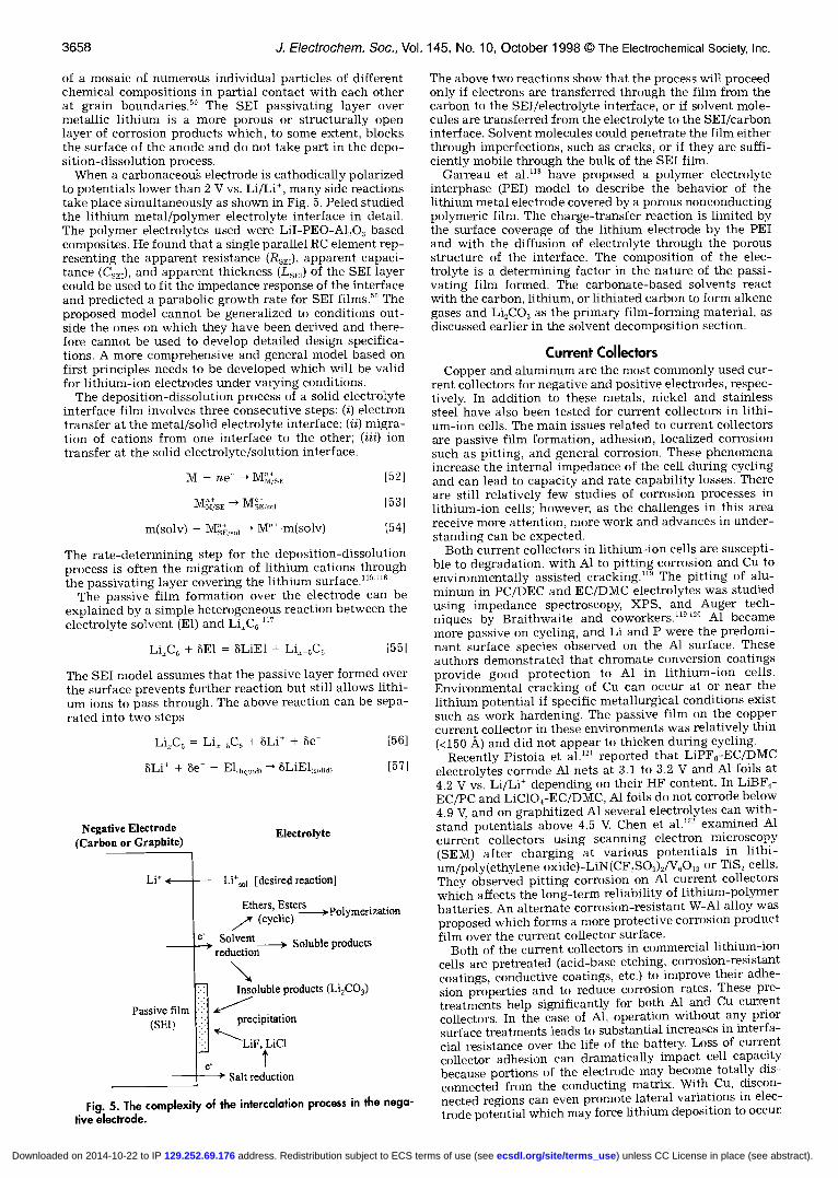
3658 1 Electrochem. Soc., Vol. 145, No. 10, October 1998 The Electrochemical Society, Inc.
of a mosaic of numerous individual particles of differentchemical compositions in partial contact with each otherat grain boundaries.58 The SET passivating layer overmetallic lithium is a more porous or structurally openlayer of corrosion products which, to some extent, blocksthe surface of the anode and do not take part in the depo-sition-dissolution process.
When a carbonaceou electrode is cathodically polarizedto potentials lower than 2 V vs. Li/Lit, many side reactionstake place simultaneously as shown in Fig. 5. Peled studiedthe lithium metal/polymer electrolyte interface in detail.The polymer electrolytes used were LiI-PEO-A1203 basedcomposites. He found that a single parallel RC element rep-resenting the apparent resistance (RSE,), apparent capaci-tance (CSE,), and apparent thickness (L5,) of the SET layercould be used to fit the impedance response of the interfaceand predicted a parabolic growth rate for SEI films.58 Theproposed model cannot be generalized to conditions out-side the ones on which they have been derived and there-fore cannot be used to develop detailed design specifica-tions. A more comprehensive and general model based onfirst principles needs to be developed which will be validfor lithium-ion electrodes under varying conditions.
The deposition-dissolution process of a solid electrolyteinterface film involves three consecutive steps: (I) electrontransfer at the metal/solid electrolyte interface; (U) migra-tion of cations from one interface to the other; (Iii) iontransfer at the solid electrolyte/solution interface.
M — ne—' MusE
MusE —*
m(solv) + Mu,,,, —' M"m(solv)
The rate-determining step for the deposition-dissolutionprocess is often the migration of lithium cations throughthe passivating layer covering the lithium surface."5"8
The passive film formation over the electrode can beexplained by a simple heterogeneous reaction between theelectrolyte solvent (El) and LiXCG
LiC6 + SE1 = BLiEl + Li_5C5 [551
The SET model assumes that the passive layer formed overthe surface prevents further reaction but still allows lithi-um ions to pass through. The above reaction can be sepa-rated into two steps
Li1C6 = LiX_5C6 + dLi + ae-
L.+- 1i e 1iquid1 1 1(s,,lidl
The above two reactions show that the process will proceedonly if electrons are transferred through the film from thecarbon to the SEI/electrolyte interface, or if solvent mole-cules are transferred from the electrolyte to the SET/carboninterface. Solvent molecules could penetrate the film eitherthrough imperfections, such as cracks, or if they are suff i-ciently mobile through the bulk of the SET film.
Garreau et al."8 have proposed a polymer electrolyteinterphase (PET) model to describe the behavior of thelithium metal electrode covered by a porous nonconductingpolymeric film. The charge-transfer reaction is limited bythe surface coverage of the lithium electrode by the PETand with the diffusion of electrolyte through the porousstructure of the interface. The composition of the elec-trolyte is a determining factor in the nature of the passi-vating film formed. The carbonate-based solvents reactwith the carbon, lithium, or lithiated carbon to form alkenegases and Li2CO3 as the primary film-forming material, asdiscussed earlier in the solvent decomposition section.
Current CollectorsCopperand aluminum are the most commonly used cur-
rent collectors for negative and positive electrodes, respec-tively In addition to these metals, nickel and stainlesssteel have also been tested for current collectors in lithi-um-ion cells. The main issues related to current collectorsare passive film formation, adhesion, localized corrosionsuch as pitting, and general corrosion. These phenomenaincrease the internal impedance of the cell during cyclingand can lead to capacity and rate capability losses. Thereare still relatively few studies of corrosion processes inlithium-ion cells; however, as the challenges in this area
1541receive more attention, more work and advances in under-standing can be expected.
Both current collectors in lithium-ion cells are suscepti-ble to degradation, with Al to pitting corrosion and Cu toenvironmentally assisted cracking." The pitting of alu-minum in PC/DEC and EC/DMC electrolytes was studiedusing impedance spectroscopy, XPS, and Auger tech-niques by Braithwaite and coworkers."5"° Al becamemore passive on cycling, and Li and P were the predomi-nant surface species observed on the Al surface. Theseauthors demonstrated that chromate conversion coatingsprovide good protection to Al in lithium-ion cells.Environmental cracking of Cu can occur at or near thelithium potential if specific metallurgical conditions existsuch as work hardening. The passive film on the coppercurrent collector in these environments was relatively thin
1561 (<150 A) and did not appear to thicken during cycling.Recently Pistoia et al.12' reported that LiPF6-EC/DMC
electrolytes corrode Al nets at 3.1 to 3.2 V and Al foils at4.2 V vs. Li/Lit depending on their HF content. In LiBF4-EC/PC and LiC1O4-EC/DMC, Al foils do not corrode below4.9 V and on graphitized Al several electrolytes can with-stand potentials above 4.5 V. Chen et al.'22 examined Alcurrent collectors using scanning electron microscopy(SEM) after charging at various potentials in hthi-um/poly(ethylene oxide)-LiN(CF,SO,)2/V60,i or TiS, cells.They observed pitting corrosion on Al current collectorswhich affects the long-term reliability of lithium-polymerbatteries. An alternate corrosion-resistant W-Al alloy wasproposed which forms a more protective corrosion productfilm over the current collector surface.
Both of the current collectors in commercial lithium-ioncells are pretreated (acid-base etching, corrosion-resistantcoatings, conductive coatings, etc.) to improve their adhe-sion properties and to reduce corrosion rates. These pre-treatments help significantly for both Al and Cu currentcollectors. In the case of Al, operation without any priorsurface treatments leads to substantial increases in interf a-cial resistance over the life of the battery. Loss of currentcollector adhesion can dramatically impact cell capacitybecause portions of the electrode may become totally dis-connected from the conducting matrix. With Cu, discon-nected regions can even promote lateral variations in elec-trode potential which may force lithium deposition to occur.
[52]
[531
Negative Electrode(Carbon or Graphite)
Electrolyte
Li Li1 [desired reaction]
Ethers,(cyclic)
Solvent__÷ Soluble productsreduction
(SET) precipitation
Salt reduction
Fig. 5. The complexity of the intercalation process in the nega-tive elecfrode.
) unless CC License in place (see abstract). ecsdl.org/site/terms_use address. Redistribution subject to ECS terms of use (see 129.252.69.176Downloaded on 2014-10-22 to IP
J. Electrochem. Soc., Vol. 145, No. 10, October 1998 The Electrochemical Society, Inc. 3659
Current collector corrosion can lead to an increase in thebattery's internal resistance over many cycles due to theformation of an insulating film of corrosion products onthe surface of the current collector. The increase in inter-nal resistance depends critically on the treatments used onthe current collector interface prior to cell assembly andcauses the battery to lose some power capability later inits life. A loss in rate capability (or increase in internalresistance) can lead indirectly to capacity loss when thecapacity is assessed at a given rate.
The dissolution of the copper current collector is a pos-sible overdischarge reaction at the negative electrode(Fig. 3)
Cu - Cu + e [58]
Univalent copper is more likely than divalent in a non-aqueous environment.123 The thermodynamic equilibriumpotential for this reaction in an aqueous solution understandard conditions is 0.521 V vs. SHE or 3.566 V vs.Li/Lit. The potential of carbon-based negative electrodesnear the end of discharge or under overdischarge condi-tions may reach in excess of 1.5 V vs. Li/Lit Apparently,this reaction occurs much more readily than expectedbecause of the nonaqueous environment in the cell, wherestandard thermodynamic data taken in aqueous media nolonger hold.
The copper ions that are formed on overdischarge canredeposit later as copper metal at the negative electrode,forming dendrites which may penetrate the separator andcause cells to fail catastrophically. These processes general-ly prevent lithium-ion cells from being discharged belowapproximately 2.5 V. This is a serious problem in bipolarstacks of cells as it is difficult to control each individual cellvoltage. Thus, a cell may be overdischarged because it hasa lower capacity, and this could destroy the whole stack.For other consumer electronics applications, it would beadvantageous for lithium-ion cells to have better overdis-charge tolerance.
Positive Electrode DissolutionPositive electrode dissolution phenomena are both elec-
trode and electrolyte specific, and limited data on theseprocesses are available for most materials. The factorsdetermining positive electrode dissolution are structuraldefects in the positive active material, high charging po-tentials, and the carbon content in the composite positiveelectrode. Oxygen defects in the LiMn,04 and LiNiO2structures may weaken the bonding force between thetransition metal and oxygen, resulting in Mn and Ni metaldissolution. The transition metal ions which have weakbonding forces with oxygen could be driven into the elec-trolyte, especially when polarized to high potentials.66Electrolyte oxidation on the carbon black surface maygenerate catalytic species which can increase the rates ofmetal-ion dissolution.
Of the three main high-voltage metal oxide positiveelectrode materials, cation dissolution has been most stud-ied to date on the lithium manganese oxide spinel. Dis-solution of the LiMn2O4 active material occurs through adisproportionation mechanism leading eventually to man-ganese deposition on the negative electrode. This causes aloss of positive active material and blocking of pores in thenegative electrode. The Mn2 dissolution reaction is be-lieved to occur when the LiMn2O4 electrode is fully dis-charged, and can be a major problem in the shelf life ofdischarged cells. These processes have been studied by anumber of authors including Thackeray and coworkersand the Beilcore research group.124-'26
The capacity fading upon cycling was first ascribed tothe dissolution of Mn by Thackeray.'28 Tarascon and co-workers detected the presence of Mn on the surface of thenegative electrode by Rutherford backscattering spec-troscopy (RBS).'27 Wen et al.'29 reported that the capacityfade on cycling in the higher voltage region was attributedto the fact that the active electrode material was gradual-ly converted to a lower voltage defect spinel phase via the
dissolution of Mn into the electrolyte. Recently Xia et al.'3°reported that capacity loss caused by the simple dissolu-tion of Mn3 accounted for only 23 and 34% of the overallcapacity loss observed at room temperature and 5 0°C,respectively. They suggested that the rest of the capacityfade originated from structural changes and decomposi-tion of the electrolyte solution.
According to Bellcore'24"27"3' and Dahn,52"32 25% of theMn2 dissociated ends up depositing on the negative elec-trode surface. This occurs via the following mech-anism52"24127131135
4W + 2LiMn3Mn4'O4 - 3X — Mn02 + Mn2
+ 2Li* + 2H20 [59]
which is the acid-induced decomposition of the spinel.'34This disproportionation process is due to the instability ofthe Mn3 oxidation state, which reacts spontaneously toform Mn2 and Mn4t Mn2 then goes into solution and re-deposits as Mn(s) at the negative electrode
Mn2 + 2e -* Mn(s) [60]
It could also be the case that colloidal LiMn2O4 particlesmove toward the negative electrode by electrophoresis anddeposit manganese at the negative electrode. However, ifelectrophoresis were taking place, the amount of man-ganese determined at the negative electrode should de-pend strongly on the particle size of the electrodes, whichwas not the case.
The above reaction (Eq. 59) is greatly accelerated withincreasing temperature. The protons arise from HF, whichoriginates with the hydrolysis of LiPF6 salt and thusdepends critically on LiPF6 purity97
H,O + LiPF6 -* POF3 + 2HF + LIF [61]
The water produced by the Eq. 59 can also generate moreprotons, making the manganese dissolution process auto-catalytic in nature. Free protons could also be consumed atthe negative electrode via
2H + 2e —* H3(g) [62]
The Mn2 dissolution reaction can be reduced or slowedby using high purity LiPF6 and low surface area LiMn9O4(<1 m2/g).'36"37 Limiting the surface area also reduces thecatalysis of side reactions such as solvent oxidation.There is experimental evidence that the hexafluorophos-phate anion is more directly involved in the manganesedissolution process, perhaps through an anion-assistedmechanism. 138
Jang et al.'39 stated that manganese dissolution is theprimary reason for capacity losses in LiMn2O4 electrodes.In this study, manganese dissolution brought about an in-crease in contact resistance at the manganese-depleted_spinel/carbon interface and also increased the electrodereaction resistances for lithium insertion-deinsertjonThey reported experimental data for the dependence ofmanganese dissolution on applied potential. The dissolu-tion rate was not appreciable when the applied potentialwas below ca. 4.0 V vs. Li/Li, but it became notably highabove 4.0 V. According to these authors, the dispropor-tionation mechanism (Eq. 59) seems unlikely to be a causefor the dissolution because dissolution was seen predomi-nantly at the end of the charging process, in which poten-tial range the Mn3 content in the spinel is minimal.
In another study, Jang and Oh'4° reported that spineldissolution is induced by acids that are generated as aresult of electrochemical oxidation of solvent molecules oncomposite cathodes. The spinel dissolution was muchhigher in the ether-containing electrolytes such as DMEand THF as compared to the carbonates. In the initialstages only Li and Mn ions are extracted, while in the laterstages oxygen loss becomes dominant. They found thatsolvent-derived acid generation was not significant inelectrolytes containing fluorinated salts (LiPF6, LiBF4,and LiAsF6), yet the spinel dissolution in these electrolytes
) unless CC License in place (see abstract). ecsdl.org/site/terms_use address. Redistribution subject to ECS terms of use (see 129.252.69.176Downloaded on 2014-10-22 to IP
3660 J. Electrochem. Soc., Vol. 145, No. 10, October 1998 The Electrochemical Society, Inc.
was appreciable because the acids are generated by thereaction between the F containing anions and impuritywater (such as Eq. 61 above).
Although the results of Jang et al. appear contradictoryto the earlier work, it is likely that a similar mechanism isoperating in all cases. Jang et al. have emphasized the im-portant link between the generation of protons in the celland manganese dissolution. By using ether-based solvents,a much larger quantity of protons is generated thus lead-ing to higher rates of manganese dissolution than wouldhave been seen in earlier studies with oxidation-resistantcarbonate solvents. The link between manganese dissolu-tion and electrode potential is due to this potential-depen-dent solvent oxidation process, not the state-of-charge ofthe positive electrode as suggested by Jang et al.
Robertson et al.'4' also proposed an alternate mechanismfor spinel dissolution. They proposed that a modified pro-ton-catalyzed redox mechanism is responsible for Mnextraction from the cathode and the concurrent formationof Li,MnO species which were electrochemically inactiveat 4 V
l2LiMn2O4 -* Li,MnO, + 5Li,Mn40,, + 3Mn [63]12Mn' — 9Mn" + 3Mn, + 6e oxidation 1641
3Mn, + 6e — 3Mn k reduction
Li,MnO, is electrochemically inert, and Li,Mn40, has vir-tually no capacity in the 4 V region. From Eq. 63 to 65,12 M of LiMn0O4 become inactive for every 3 M of Mn2'that dissolve into the electrolyte. Moreover, Li,Mn40, cyclesin the 2 to 3 V domain. They suggested that low levels ofCr3 in the spinel framework can substantially reduce cath-odic manganese dissolution into the electrolyte.
Based on the evidence for the dissolution of manganeseand the change in crystal structure of the spinel duringcycling, Xia et al."° proposed that manganese dissolves viatwo routes: (1) LiMn9O4 is transformed to LiMn, x04_x, vialoss of MnO, and, (ii) LiMn3O4 is transformed toLi,,rMn,_r04, via loss of Mn,04. For the first case, a por-tion of Mn3 transforms to Mn4' together with dissolutionof MnO into solution, i.e.
Mn'(LiMn,O4) -* Mn"(Li2Mn,O,) + Mn2(MnO) [661
Amatucci et al.'42 reported a strong and direct relation-ship between capacity loss and percentage of cobaltdetected on the negative electrode for LiCoO,-based lithi—urn-ion cells charged above 4.2 V. The capacity loss (or Codissolution) depended on the thermal treatment duringsynthesis of the active material. Cobalt ions present in theelectrolyte after dissolution are reduced at the negativeelectrode. The rate of dissolution increases with cutoffvoltage, with a steep increase when the cutoff voltage is4.5 V A quantitative relationship between the percentageof cobalt dissociated and capacity loss for LiCoO, cellswith a cutoff (charging) voltage of greater than 4.2 V wasgiven by these authors.
In certain lithium-vanadium oxide (Li4V9O,) cells basedon an LiAsF,_EC/PC/2Me-THF (15:70:15) electrolyte,vanadium was found to dissolve partially and then plateon the lithium electrode leading to an increase in cyclelife.'43 The vanadium incorporated into the lithium surfacefilm was shown to be beneficial to the passive film prop-erties in this electrolyte. This work demonstrates the elec-trode material and cell-specific nature of the dissolutionprocess and its impact on battery performance.
Phase Changes in Insertion Electrodes
The understanding of the relationship between phasechanges in insertion electrodes and capacity loss is weakeven though this is widely quoted as a mechanism of capac-ity loss. The basic mechanism stated is that phase changesor large changes in lattice parameters leads to fracture ofparticles and loss of contact from the electrode matrix. Ingeneral, one might believe that good electrodes showinghigh reversibility and cycle life probably are not accompa-
nied by significant phase changes or lattice expansion orcontraction during operation. The three main metal oxideinsertion compounds most studied currently for lithium-ionbatteries are in this category. However, the constant searchfor higher capacity materials makes phase changes andstructural changes difficult to avoid, and the effects of theseprocesses on battery performance is only beginning to bequantified and studied in a fundamental manner.
The phase changes occurring in lithium-ion cells can beclassified into two types: those that occur during normalinsertion-deinsertion of lithium, and others that occurwhen the positive electrode is overcharged or overdis-charged (for example, the Jahn-Teller distortion'44 in thecase of overdischarge of Li4Mn,04 above y = l).'' Xiaet al.'43 and Ohzuku et al.'44 have studied the phasechanges occurring in spinel LiMn2O., electrodes. Xia et al.concluded that the transformation of unstable two-phaseto a more stable one-phase structure occurs via loss ofMnO (Mn't -÷ Mn4 + MnO), which dominates the capaci-ty fading during the room temperature cycling of cells.
Amatucci et al."4 described the insertion of lithium intoLiMn,04 as single phase and biphase. The biphase inser-tion scheme as proposed by them is
100-250°C +Li[65] Li4Mn2O4 — X — Mn904 —> l3-MnO., — LiMnO9 [67]
- Mn904 -* Mn204 -* - Mn02 [68]
Delithiation of Li4Mn,04 leads to formation of X-Mn904that decomposes to ll-MnO, at temperatures ranging from100 to 250°C, and in some cases €-Mn204 may be detectedas an intermediate in the process of decomposition. Rutile13-Mn01 is electrochemically inactive at 4 V and leads tothe formation of orthorhombic LiMnO9 on lithium inser-tion. These phase changes during cycling may lead tocapacity losses in practice. Recently, Cairns et al.'46 haveused in situ X-ray adsorption techniques to determine thatupon delithiation of LiMn,04, the lattice contracts to astructure similar to k-Mn02, whereas lithiating LiMn,04transforms the cubic spinel into the tetragonal phaseLi2MnO4.
Another major reason for capacity fade in LiMn,04spinel-based cells is overdischarge leading to a lower than3.5 average oxidation state for manganese.'2' This maycause a Jahn-Teller distortion of the LiMn9O4 structure thatoccurs when the oxidation state drops below 35121146-14During the Jahn-Teller distortion, the z axis stretches by15% and the x and p axes contract by 6%. The large aniso-tropic expansion (16%) of the unit cell is too severe for thetetragonal Li9Mn2O4 phase on the surface and cubicLiMn2O4 in the bulk to remain as one intergrown structurewithin a single crystallite. Particle fragmentation mayresult (giving higher surface area), causing the Mn3t disso-lution reaction to become more troublesome and leading toloss of contact between particles. This structural damage tothe spinel electrode may lead to slow capacity loss oncycling.
The Jahn-Teller distortion process is greatly reduced byusing an excess of lithium in the LiMn,04 starting materi-al (x = 1.05 or higher). Lithium substitution into man-ganese sites leads to an increase in the average oxidationstate for the manganese. This has also been accomplishedby doping LiMn,04 with other atoms such as cation sub-stitution with Fe or Co,'49" or anion substitution withF. 152,'53 Lithium manganese oxide spinel electrodes stabi-lized in some manner to prevent overdischarge can exhib-it constant capacity during cycling for several thousandcycles at room temperature.
Ohzuku et al.'44 concluded that the reduction ofLi4Mn,04 proceeds in three steps, which consist of acubic/cubic two-phase reaction, a cubic one-phase reac-tion, and a cubic/tetragonal two-phase reaction as shownin Table II. A large voltage drop of 1 V is observed for p1, which is due to a Jahn-Teller distortion of Mn06-octa-hedron from 0,, symmetry to D4,, symmetry. According tothese authors, the apparent stabilization energy of MnO,-
) unless CC License in place (see abstract). ecsdl.org/site/terms_use address. Redistribution subject to ECS terms of use (see 129.252.69.176Downloaded on 2014-10-22 to IP
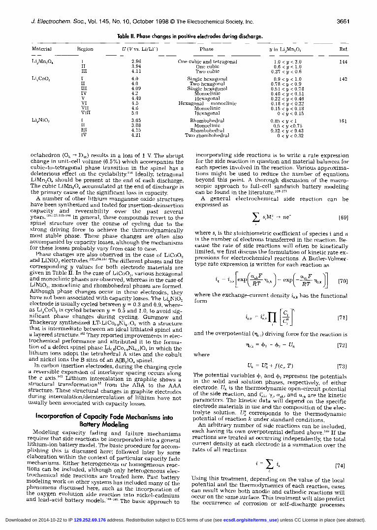
J. Electrochem. Soc., Vol. 145, No. 10, October 1998 The Electrochemical Society, Inc. 3661
Table II. Phase changes in positive electrodes during discharge.
Material Region U (V vs. Li/Lit) Phase y in Li9Mn2O4 Ref.
IIIII
IIIIIIvVVIVIIVIII
IIIIIIV
2.963.944.11
4.04.04.094.24.494.54.65.0
3.653.884.154.21
One cubic and tetragonalOne cubicTwo cubic
Single hexagonalTwo hexagonal
Single hexagonalMonoclinicHexagonal
Hexagonal -- monoclinicMonoclinicHexagonal
RhombohedralMonoclinic
RhombohedralTwo rhombohedral
1.0 <y <2.00.6< y < 1.0
0.27 <y < 0.60.9 <y < 1.0
0.78 < y < 0.90.51 < y < 0.780.46 <y < 0.510.22 <y < 0.460.18 <y < 0.220.15 <y < 0.18
0< y < 0.150.85 <y < 1
0.5 <y <0.750.32 <y < 0.43
0 < y < 0.32
octahedron (Oh D46) results in a loss of 1 V. The abruptchange in unit-cell volume (6.5%) which accompanies thecubic-to-tetragonal phase transition in the spinel has adeleterious effect on the cyclability.'54 Ideally, tetragonalLiMnO4 should be present at the end of each discharge.The cubic LiMn2O4 accumulated at the end of discharge isthe primary cause of the significant loss in capacity.
A number of other lithium manganese oxide structureshave been synthesized and tested for insertion-deinsertioncapacity and reversibility over the past severalyears.'25"27"5516° In general, these compounds revert to thespinel structure over the course of cycling due to thestrong driving force to achieve the thermodynamicallymost stable phase. These phase changes are often alsoaccompanied by capacity losses, although the mechanismsfor these losses probably vary from case to case.
Phase changes are also observed in the case of LiCoO,and LiNiO, electrodes.'42,'5416' The different phases and thecorresponding y values for both electrode materials aregiven in Table II. In the case of LiCoO2, various hexagonaland monoclinic phases are observed, whereas in the case ofLiNiO2, monoclinic and rhombohedral phases are formed.Although phase changes occur in these electrodes, theyhave not been associated with capacity losses. The Li9NiO2electrode is usually cycled between y = 0.3 and 0.9, where-as Li5CoO2 is cycled between p = 0.5 and 1.0, to avoid sig-nificant phase changes during cycling. Gummow andThackeray synthesized LT-LiCo6 9Ni,, 102 with a structurethat is intermediate between an ideal lithiated spinel anda layered structure. 162 They reported improvements in elec-trochemical performance and attributed it to the forma-tion of a defect spinel phase Li0,[Co,6Ni02]O4 in which thelithium ions adopt the tetrahedral A sites and the cobaltand nickel ions the B sites of an A[B2]04 spinel.
In carbon insertion electrodes, during the charging cyclea reversible expansion of interlayer spacing occurs alongthe c axis.'63 Lithium intercalation in graphite shows astructural transformation43 from the ABA to the AAAstructure. These structural changes in graphite electrodesduring intercalation/deintercalation of lithium have notusually been associated with capacity losses.
Incorporation of capacity Fade Mechanisms intoBattery Modeling
Modeling capacity fading and failure mechanismsrequires that side reactions be incorporated into a generallithium-ion battery model. The basic procedure for accom-plishing this is discussed here; followed later by someelaboration within the context of particular capacity fademechanisms. Either heterogeneous or homogeneous reac-tions can be included, although only heterogeneous elec-trochemical side reactions are treated here. Past batterymodeling work on other systems has included many of thephenomena discussed here, such as the incorporation ofthe oxygen evolution side reaction into nickel-cadmiumand lead-acid battery models.'64'6 The basic approach to
incorporating side reactions is to write a rate expressionfor the side reaction in question and material balances, foreach species involved in the reaction. Various approxima-tions might be used to reduce the number of equationsbeyond this point. A thorough discussion of the macro-scopic approach to full-cell sandwich battery modelingcan be found in the literature.169-'7'
A general electrochemical side reaction can beexpressed as
s,M — n& [69]
where s, is the stoichiometric coefficient of species i and nis the number of electrons transferred in the reaction. Be-cause the rate of side reactions will often be kineticallylimited, we first discuss the formulation of kinetic rate ex-pressions for electrochemical reactions. A Butler-Volmer-type rate expression is written for each reaction as
[ (aF ( csF 1=iOk[eXP,11Sk)_ exp__r__ii,)j [70]
where the exchange-current density ok has the functionalform
Zok = ZOkITI [T [71]
and the overpotential (liok) driving force for the reaction is
where
11s,k = 4)1 U6
U6 = U + f(c, T)
[72]
[73]
The potential variables 4>1 and 4). represent the potentialsin the solid and solution phases, respectively, of eitherelectrode. U6 is the thermodynamic open-circuit potentialof the side reaction, and 'y,, Uak, and a6 are the kineticparameters. The kinetic data will depend on the specificelectrode materials in use and the composition of the elec-trolyte solution. U corresponds to the thermodynamicpotential of reaction k under standard conditions.
An arbitrary number of side reactions can be included,each having its own overpotential defined above.169 If thereactions are treated as occurring independently, the totalcurrent density at each electrode is a summation over therates of all reactions
[74]
Using this treatment, depending on the value of the localpotential and the thermodynamics of each reaction, casescan result where both anodic and cathodic reactions willoccur on the same surface. This treatment will also predictthe occurrence of corrosion or self-discharge processes
Li9Mn,O4
Li4CoO2
Li5NiO,
144
142
161
) unless CC License in place (see abstract). ecsdl.org/site/terms_use address. Redistribution subject to ECS terms of use (see 129.252.69.176Downloaded on 2014-10-22 to IP
3682 J Electrochem. Soc., Vol. 145, No. 10, October 1998 The Electrochemical Society, Inc.
under open-circuit conditions. Obviously, the rates of allof the reactions are coupled through the potentials of eachphase in the porous electrode and a numerical solution ofthe governing equations is necessary.
For many side reactions, the assumption of an irre-versible reaction will hold, in which case the above rateexpression can be simplified. A Tafel expression can beinserted in place of the Butler-Volmer equation
* . (a,,F'6 = to.k exp(—-. l,k
For a side reaction obeying a Tafel equation, the value ofthe open-circuit potential becomes arbitrary because thereis no longer a backward reaction. Thus, the only kineticparameters of interest are the exchange-current densityand Tafel slope (or transfer coefficient).
Once kinetic equations have been developed and rateexpressions written, the number of species existing in thesystem and their relative importance can be assessed. Ma-terial balances can be written on each species existing inthe system, although the concentrations of species in-volved in homogenous chemical reactions might be relatedthrough reaction equilibria.
The material balance for species i can be written in theform
L=_V.N +Rdt —
where c, and N, are the concentration and molar flux ofspecies i. The net rate of production of species i is given byR1. This quantity applies to either bulk homogenous reac-tions or heterogeneous reactions if the latter are treatedusing a pseudohomogenous averaging approach. Underporous electrode theory, the rate of production of a givenspecies can be related to the partial current densities of theelectrochemical reactions according to'6'
R =— a,,—i9
where a,, is the specific interfacial area per unit volume ofelectrode. If the electrochemical reaction is localized ontoa particular surface, such as the current collectoL the gen-eration of material can be included in a boundary condi-tion. Different approximations will be valid depending onthe phase of the species (solid, liquid, gases) and the con-centrations present. In many cases, the rate of a side reac-tion will be low enough or the quantity of a species gener-ated small enough that a material balance can beneglected entirely.
Often transport processes in the cell are described usingconcentrated solution theory which accounts for interac-tions between each pair of species.'69 With a larger numberof species present due to side reactions, simplificationsmay be made to this rigorous treatment to reduce the num-ber of transport properties required in the model. For ex-ample, the electrolyte solution might be treated as com-posed of a primary solvent, a single salt, and an arbitrarynumber of solution-phase pseudo-dilute species. Interac-tions between the primary solvent and salt are treated rig-orously as a binary electrolyte system, while the dilutespecies are treated as interacting with the primary solventonly. This simplified treatment generates (3 + a) transportproperties or D,,'s where a is the number of dilute speciesrather than the (3 + m)(2 + n)/2 required in the more rig-orous treatment. Neglected in this treatment are interac-tions between the various dilute species and interactionsof dilute species with the salt.
Under these simplifications, the flux of a dilute nonion-ic component might be written simply as
N, = —D01Vc,
where D0, is an interaction parameter or diffusion coeffi-cient representing motion of species i through the solvent.
The flux of a dilute ionic component is composed of theabove diffusive flux as well as a migration components
N = —D0Vc r.Pr7FcV [79]RT
If the concentration of a dilute ionic component is lowenough, migration can be neglected entirely because theprimary salt will act as a supporting electrolyte. In both ofthe above expressions, convective fluxes are neglectedwhich is usually a good approximation. These flux expres-sions are substituted into the material balance above(Eq. 76) to provide an equation for the concentration of adilute species as a function of time and position across thecell. Initial and boundary conditions are needed to com-plete the problem.
The phase of a given species is an important considera-tion in determining the level of sophistication required inthe model. For example, gaseous species might be treatedas existing purely in a vapor space above the cell, and theirconcentrations might be assumed uniform because of fasttransport of gas-phase species. Under these assumptions,the pressure developed inside the cell could be assessed(assuming the system is at constant volume) and the rela-tive partial pressures of each species determined. In othercases, the solubility of gases in tke electrolyte may be animportant factor in cell performance or self-dischargeprocesses, in which case these assumptions would not bemade. The three phases (solid, solution, and gas) can betreated as superimposed continuous phases without regardto the geometric details of the pore structure using porouselectrode theory.'°'
Solid-phase species with low solubility might be treatedas localized, such as with the precipitation of salts in pre-vious battery modeling Reactive interme-diates, such as radical species resulting from solvent oxi-dation or reduction processes, are often treated using thepseudo-steady-state approximation, wherein the net rateof formation of the species is assumed to be zero.'77 Fur-
[77]ther consequences of these assumptions will be discussedin the remainder of this section.
Film growth.—Side reactions that lead to growth of afilm on the surface of the electrode particles are seen inseveral instances within tke lithium-ion battery. Passiva-tion of the carbon-based negative electrode with associat-ed film or SEI layer formation is a standard process in allcells. Abuse conditions such as overcharge can lead to filmformation from the deposition of metallic lithium onto thenegative electrode. Any lithium metal formed in the cellwill probably undergo secondary reactions leading to morethick reaction product layers or secondary films. Otherside reactions can also lead indirectly to film formationbecause of the formation of products with low solubility inthe nonaqueous solvents.
We start by discussing film formation due to overchargeof the negative electrode and deposition of metallic lithi-um because this process is possible in all lithium-ion bat-teries in theory and presents an important safety concernwith commercial cells. A number of different approxima-tions can be used to include the lithium metal depositionside reaction in lithium-ion battery models. For this rea-son, the detail of a model is driven primarily by its intend-ed usage, with models having more predictive power need-ing a greater level of detail. Before decisions can be madeon the sophistication needed, overcharge experimentaldata for lithium-ion cells using coke and graphite as neg-ative electrodes are needed. Based on these data, theeffects of overcharge on the discharge and cycle life of thebattery can be assessed, and the phenomena that must beincorporated into models determined. Also, kinetic datafor the lithium deposition reaction are needed under theappropriate conditions.
178]Because the lithium deposition reaction is a facile process
under many conditions, the surface overpotential will below and the reaction can be described adequately using thelinear approximation to the Butler-Volmer equation
[75]
[76]
) unless CC License in place (see abstract). ecsdl.org/site/terms_use address. Redistribution subject to ECS terms of use (see 129.252.69.176Downloaded on 2014-10-22 to IP
J. Electrochem. Soc., Vol. 145, No. 10, October 1998 The Electrochemical Society, Inc. 3663
(a +a)F¼ = o,k RT
For solids such as metallic lithium, the flux will be zero toa very good approximation. By integrating the materialbalance over the volume of the negative electrode, the rateof the side reaction can be related to the growth of a filmon the surface of the electrode particles
— ikMdt LapF
where 8 is the film thickness composed of solid lithiumand other lithium products, and L_ represents the thick-ness of the negative electrode.
This film thickness, along with assumed properties for thefilm such as conductivity and dielectric constant, can beincorporated into a battery model to predict the impact ondischarge performance or electrochemical impedance data.A similar approach was taken by Pollard to treat precipita-tion of salt films in electrochemical cells.175 As the filmthickens dynamically during simulation of the cell chargeand discharge, the interfacial resistance will increase andthe current distribution in the electrodes will change. Also,the capacity balance in the cell is modified due to the sidereaction current density. Other effects can then be incorpo-rated such as porosity changes in the electrode and sec-ondary side reactions with the deposited lithium.
Another side reaction of general interest in lithium-ionbatteries is passive film formation on the negative elec-trode during the initial cycling or formation period. Mod-eling passive film formation is similar to the modeling oflithium deposition during overcharge conditions. How-ever, the reduction reactions taking place which lead to thedeposition of solid products are much less well under-stood, larger in number, and varied in their nature depend-ing on the composition of the electrolyte solution as seenin an earlier section. For these reasons, a great simplifica-tion might be made where the passivation process is treat-ed as the consumption of solvent and lithium ions to forma single homogeneous product such as lithium carbonate.The passivation process at the electrode/electrolyte inter-face can be modeled to allow the film thickness and otherrelevant properties to be tracked during cycling. Other in-termediate species formed such as radicals could be eitherneglected completely or treated in a simplified manner (forexample, these might be included to track the rate of self-discharge). By following the rate of solvent, lithium ion,and electron consumption by the passivation process, theimportant effects of the side reaction on the capacity bal-ance in the cell can still be assessed.
Under the assumptions given above, the film is modeledas a one-dimensional layer having a time-dependent filmthickness. The film thickness is calculated from the partialcurrent density of the reduction side reaction. Because theexact nature of the side reaction is either not known or isbeing simplified greatly, the rate expression used wouldprobably be obtained by empirical fits to experimentaldata such as charge and discharge curves during the for-mation period. The film thickness calculated from themodel is related to a film resistance and capacitance usingassumed physical properties. Because the resistance of thefilm changes with time, an increase in interfacial resist-ance and a capacity loss in the cell will result. Assumingthat the rate-limiting step in the charge-transfer process isbulk migration of lithium through this passive layer asstated earlier, then the treatment of the film as a pureresistor is justified. In other cases, the finite rate of thecharge-transfer process at either interface may also be animportant consideration. Finally, if the film has someporosity or if it is not a pure cation conductor, then diffu-sion limitations inside the film might also be included.172
Electrolyte decomposition reactions—A large numberof different solvent and salt combinations are used in lithi-um-ion batteries. Because of the complexity of the mech-anisms of salt and solvent oxidation and reduction reac-
tions, it is not possible at present to create a general model[80] that can treat all possible systems. Future modeling work
in this area will almost certainly be confined to specificand well-studied systems. The modeling of electrolyte de-composition reactions is not difficult mathematically, butfor complicated multistep mechanisms, the number ofequations and unknowns make the solution procedurecomputationally demanding. Kinetic data for each reac-tion and transport property data for each species are intheory needed. It should be possible to treat these systemsby making use of standard approaches such as the pse9do-steady-state or rate-limiting-step approximate methods.177
A rigorous treatment of side reactions involving the sol-vent and salt species in lithium-ion cells would requiresubstantial amounts of fundamental data on the rates ofthese processes so that information such as rate-limitingsteps can be assessed. Fortunately, for the practical pur-pose of treating side reactions in battery modeling andpredicting their consequences to cell performance, thislevel of detail is probably unnecessary, and advances in theunderstanding of these processes can be made using thepresent state of knowledge in the literature. Side reactionsinvolving both oxidation and reduction of components ofthe electrolyte solution are lumped together in this sectionbecause similar issues exist in modeling both situations,such as the loss of solvent or salt from the system, forma-tion of product species which may take part in secondaryprocesses or reactions, and perturbation of the cell'scapacity balance.
In many current lithium-ion battery models, the open-circuit potential of the positive electrode is forced to inf in-ity as the value of y reaches its minimum value (e.g., U —
as y — 0.4 for Li5CoO2) and no side reactions involvingelectrolyte oxidation are considered. Applying this condi-tion to the open-circuit potential for the insertion elec-trode stops the insertion process at the desired stoichiom-etry in an artificial manner by forcing the electrodepolarization to infinity. Side reactions (both chemical andelectrochemical) could be included in a battery model assecondary processes that proceed in parallel to the mainreaction with their own separate kinetic expressions. Theelectrochemical side reactions depend on the local elec-trode potential and are often treated adequately usingTafel equations due to the irreversible nature of many ofthese processes.35 Chemically or thermally induced degra-dation processes do not depend on electrode potential andmight be more important under conditions of abuse.
The presence of these side reactions can have a numberof dramatic consequences in a battery model. By trackingthe rates of the oxidation or reduction processes occurringas side reactions, the actual lithium stoichiometry in thetwo insertion electrodes is predictable even during abuseconditions. This allows capacity fading to be predicted aswell as the potential hazards associated with accumulatedloss of capacity in one electrode. In many cases, the loss ofsalt or solvent from the cell will represent a very smallfraction of the total electrolyte, and this effect on the cell'sperformance might be neglected entirely. However, overlong-term cycling of the cell, it is possible that the accu-mulated loss of electrolyte from the system will begin tomanifest itself in losses of rate capability or cell capacity.Products formed in the side reactions can also be moni-tored and their role in secondary processes such as self-discharge followed. These products might be solutionphase, gaseous, or solid depending on the nature of theside reaction, and in each case different approximationsare warranted as discussed earlier.
In some cases, the active electrode material itself maytake part in the side reaction. For example, the acid-induced delithiation and dissolution of the manganeseoxide spinel material is a case where solvent oxidation orsalt hydrolysis processes lead to the formation of products(protons) that participate in secondary reactions with theelectrode material. Often these processes will lead to for-mation of electrochemically inactive products either dueto blockage of the electrode particle surface due to precip-
[81]
) unless CC License in place (see abstract). ecsdl.org/site/terms_use address. Redistribution subject to ECS terms of use (see 129.252.69.176Downloaded on 2014-10-22 to IP
3664 J Electrochem. Soc., Vol. 145, No. 10, October 1998 The Electrochemical Society, Inc.
itation of solid-phase species or because of conversion tomaterials with either limited reversibility or no lithiuminsertion capacity in the voltage range of interest.
Modeling these processes requires a mass balance foreach species involved in the side reactions, especially thoserelated to consumption of active materials and formationof inert products. A more simplistic method of accountingfor the formation of inert or nonelectrochemically activemetal oxide compounds is to adjust the volume fraction ofactive material as the side reaction proceeds, increasingthe volume of inert filler in proportion to the rate of activematerial consumption. For example, by tracking the pro-duction of protons inside the cell under abuse conditions(such as solvent oxidation), the rate of electrode dissolu-tion and conversion to nonactive materials can also be fol-lowed. These nonactive materials could be treated as uni-formly distributed throughout the composite electrodesimilar to the standard treatment of polymer binders andcarbon-black additives under porous electrode theory.
Corrosion and dissolution processes—Additional ionicspecies can make their way into the cell due to the process-es of electrode dissolution and current collector corrosion.Cationic species other than lithium can create problemsfor cell performance because they are more easily re-ducible than lithium ions and will generally end up depos-iting on the negative electrode during charging conditions.In the worst case, these processes lead to dendritic growththrough the separator and short circuit of the cell. Thepresence of deposited manganese and cobalt have beenmentioned in the literature,52 125131139142 and corrosion ofcurrent collector materials such as copper and aluminumis also well documented.11912' Modeling these phenomenaappears challenging due to our limited understanding ofthe fundamental processes occurring and the fate ofmetallic impurities inside the nonaqueous environment ofthe cell (other than their eventual likely fate at the nega-tive electrode).
For example, it would be useful to predict the onset ofcopper dissolution at the negative electrode under overdis-charge conditions. This might allow more optimum designof cells to limit the maximum negative electrode potentialand prevent significant loss of copper. Unfortunately, thecopper dissolution-deposition voltage is difficult to pre-dict because very little data are available for nonaqueoussystems. For any given nonaqueous electrolyte system, thethermodynamic open-circuit potential for copper dissolu-tion must be assessed experimentally. If these data wereknown or assumed, the copper dissolution reaction couldbe modeled in a manner similar to the treatment of lithi-um deposition during negative-electrode overcharge byusing a Butler-Volmer-type rate equation and a materialbalance on solution-phase copper species. However, thegrowth of dendrites leading to cell short circuit is moredifficult to predict because this is a function of depositionmorphology.
The related topic of electrode dissolution in LiMn3O4-based cells can be included in battery models by adding theacid-assisted dissolution mechanism discussed earlier as aside reaction. Equation 59 occurs on the surface of the pos-itive electrode, LiPF6 hydrolysis is a homogenous chemicalreaction, and H3 evolution occurs at the surface of the neg-ative electrode. Note that these processes are potentiallyautocatalytic as water generated by the dissolution of thelithium manganese oxide spinel can create more protonsfrom hydrolysis of the salt. These reactions can be includ-ed in a cell model by writing material balances for eachspecies, although a number of simplifications are sure to bewarranted. The rate equation (Butler-Volmer expressionfor electrochemical reactions) for each reaction could bewritten in the same manner as shown previously (Eq. 70).Positive active material is lost when electrode dissolutionoccurs leading to capacity loss. Also, dissolved manganeseis reduced at the negative electrode and blocks pores orsurface area again leading to capacity loss.
Self-discharge processes—Although self-discharge is animportant phenomena for practical commercial cells, ithas received relatively little attention in the battery mod-eling literature. However, the modeling of self-dischargeprocesses is straightforward once a full-cell-sandwichbattery model exists and once the necessary side reactionshave been incorporated into the model. Self-dischargeprocesses can be separated into those involving a singleelectrode such as the coupled electrolyte decompositionand lithium insertion-deinsertion reactions discussed ear-lier, and those that involve interactions between the twoelectrodes such as redox processes and short-circuiting.
Self-discharge processes involving a single electrode canbe treated by simply adding the kinetics for the electrolytedecomposition reaction as well as Eq. 74 to the overallmathematical model. For example, self-discharge of ahigh-voltage positive electrode would be modeled by in-cluding the oxidation of solvent species such as the car-bonates using a Tafel rate expression.35 Because of the be-havior of the Tafel equation, the solvent oxidation processwould occur at all voltages but would increase dramati-cally at higher voltages dependent on the values used forthe exchange-current density and transfer coefficient forthe oxidation reaction. When the current is interrupted ina model of this kind, rather than attaining a constant volt-age, the cell voltage will decrease spontaneously as lithi-um intercalation into the positive electrode is balancedagainst the solvent oxidation process.
Other self-discharge mechanisms could also be includedin a macroscopic battery model without much trouble.Leakage currents are included in modeling by carrying outthe constant resistance discharge of the cell under other-wise open-circuit conditions. It might be possible to meas-ure the proper value of resistance to use for the dischargeor this value might be fit against experimental self-dis-charge data. Redox-shuttle-type self-discharge mechan-isms require a source for the redox species, such as a sol-vent decomposition reaction, as well as a material balanceon the species in question to predict its transport rateacross the cell and concentration (both of which impactthe self-discharge rate). Self-discharge processes havebeen verified experimentally in the literature describedearlier, but more experimental data will be needed to val-idate model predictions using well-characterized systems.
AcknowledgmentsThe authors acknowledge the financial support from the
Office of Research and Department of the United StatesCentral Intelligence Agency for this project under contractno. 93-F148100-l00. The authors also acknowledge usefuldiscussions on capacity fade mechanisms with Dr. A. S.Gozdz of Bellcore.
Manuscript submitted November 18, 1997; revised man-uscript received April 17, 1998.
The University of South Carolina assisted in meeting thepublication costs of this article.
LIST OF SYMBOLSak specific interfacial area per unit volume of electrode,
cm 1c concentration of species i, mol/cm3C theoretical coulombic capacity of insertion material
based on discharged state, mAh/gCirr excess capacity in negative electrode, mAh/gEl electrolyte constituentF Faraday's constant, 96487 C/equivi current density, A/cm2
exchange current density of reaction k, A/curvi mass of active material in composite electrode, gM molecular weight, g/molL thickness of electrode, jimn number of electrons transferred in electrochemical
reactionsmolar flux of species i, mol/cm2 s
R ideal gas constant, 8.314 J/ mol KR1 rate of generation of species i, mol/crn3 ss stoichiometric coefficient of species it time, s
) unless CC License in place (see abstract). ecsdl.org/site/terms_use address. Redistribution subject to ECS terms of use (see 129.252.69.176Downloaded on 2014-10-22 to IP

J. Electrochem. Soc., Vol. 145, No. 10, October 1998 The Electrochemical Society, Inc. 3665
T temperature, KU open-circuit potential, Vx stoichiometric coefficient of negative electrodey stoichiometric coefficient of positive electrodeGreeka transfer coefficient-y reaction order of species i or mass ratio of electrodes
thickness, cmvolume fraction of active material in electrode
p density, g/cm3surface overpotential, V
4' electric potential, VSubscriptso with respect to initial conditions1 solid matrix2 solution phase+ positive electrode— negative electrodea anodec cathodek reaction numbers separatorSuperscriptsO standard cell potential
REFERENCES1. B. Scrosati, J. Electrochem. Soc., 139, 10 (1992).2. S. Megahed and B. Scrosati, Elect rochem. Soc. Inter-
face, 4(4), 34 (1995).3. T. Nagaura, Prog. Batteries Battery Mater., 10, 218
(1991).4. K. G. McColl, J. Power Sources, 48, 29 (1994).5. D. Linden, Handbook of Batteries and Fuel Cells, 1st
ed., McGraw-Hill Book Company, New York (1984).6. K. M. Abraham, Elect rochim. Acta, 38, 1233 (1993).7. K. Brandt, Solid State lonics, 69, 173 (1994).8. K. Sekai, H. Azuma, A. Omaru, S. Fujita, H. Imoto, T.
Endo, K. Yamaura, and Y. Nishi, J. Power Sources,43-44, 241 (1993).
9. K. Ozawa, Solid State lonics, 69, 212 (1994).10. B. A. Johnson and R. E. White, J. Power Sources,
70/1, 48 (1998).11. S. Yoda, .1. Power Sources, 68, 3 (1997).12. B. C. Knutz, K. West, B. Z.-Christiansen, and S.
Atlung, J. Power Sources, 43-44, 733 (1993).13. K. West, T. Jacobsen, and S. Atlung, J. Electrochem.
Soc., 129, 1480 (1982).14. S. Atlung, K. West, and T. Jacobsen, J. Electrochem.
Soc., 126, 1311 (1979).15. 5. Atlung, B. Z,-Christiansen, K. West, and T. Jacob-
sen, J. Electrochem. Soc., 131, 1200 (1984).16. Z. Mao and R. E. White, J. Power Sources, 43-44, 181
(1993).17. R. M. Spotnitz, D. Zuckerbrod, S. L. Johnson, J. T.
Lundquist, and R. E. White, in Proceedings of theSymposium on Modeling of Batteries and FuelCells, R. E. White, M. W. Verbrugge, and J. F Stock-el, Editors, PV 91-10, p. 88, The ElectrochemicalSociety, Proceedings Series, Pennington, NJ (1991).
18. M. Doyle, T. F Fuller, and J. Newman, J. Electrochem.Soc., 140, 1527 (1993).
19. T. F Fuller, M. Doyle, and J. Newman, J. Electrochem.Soc., 141, 1 (1994).
20. M. Doyle, Ph.D Thesis, University of California,Berkeley, CA (1995).
21. T. F Fuller, M. Doyle, and J. Newman, J. Electrochem.Soc., 141, 982 (1994).
22. M. Doyle, J. Newman, A. S. Gozdz, C. N. Schmutz,and J. M. Tarascon, J. Electrochem. Soc., 143, 1890(1996).
23. M. Doyle, J. Newman, and J. Reimers, J. PowerSources, 52, 211 (1994).
24. M. Doyle and J. Newman, J. Power Sources, 54, 46(1995).
25. Y. Chen and J. W. Evans, J. Electrochem Soc., 140,1833 (1993).
26. Y. Chen and J. W. Evans, J. Electrochem Soc., 141,2947 (1994).
27. Y. Chen and J. W. Evans, J. Electrochem Soc., 143,2708 (1996).
28. C. R. Pals and J. Newman, J. Electrochem Soc., 142,3274 (1995).
29. C. R. Pals and J. Newman, J. Electrochem Soc., 142,3282 (1995).
30. M. W. Verbrugge and B. J. Koch, J. Electrochem. Soc.,143, 24 (1996).
31. M. W. Verbrugge and B. J. Koch, J. Elect rochem. Soc.,143, 600 (1996).
32. S. R. Narayanan, S. Surampudi, A. I. Attia, and C. P.Bankston, J. Electrochem. Soc., 138, 8 (1991).
33. R. Darling and J. Newman, J. Electrochem. Soc., 144,4201 (1997).
34. G. Nagarajan, J. W. VanZee, and R. M. Spotnitz, J.Electrochem. Soc., 145, 771 (1998).
35. F. Darling and J. Newman, J. Electrochem. Soc., 145,990 (1998).
36. M. Armand, Solid State lonics, 9&10, 745 (1983).37. J. M. Tarascon and D. Guyomard, Electrochim. Acta,
38, 1221 (1993).38. D. Guyomard and J. M. Tarascon, Solid State lonics,
69, 222 (1994).39. R. Pollard and J. Newman, J. Electrochem Soc., 128,
491 (1981).40. A. B. Yu, R. P. Zou, and N. Standish, md. Eng. Chem.
Res., 35, 3730 (1996).41. D. Guyomard and J. M. Tarascon, J. Electrochem.
Soc., 139, 4 (1992).42. R. Fong, U. von Sacken, and J. R. Dahn, J. Elec-
trochem. Soc., 137, 2009 (1990).43. D. Fauteux and R. Kosbang, J. Appl. Electrochem.,
22, 1 (1992).44. T. Zheng, Y. Liu, E, W. Fuller, S. Tseng, U. von Sack-
en, and J. R. Dahn, J. Electrochem. Soc., 142, 2581(1995).
45. W. Xing and J. R. Dahn, J. Electrochem. Soc., 144,1195 (1997).
46. J. R. Dahn, T. Zheng, Y. Liu, and J. S. Xue, Science,270, 590 (1995).
47. J. M. Tarascon and D. Guyomard, J. Electrochem.Soc., 138, 2865 (1991).
48. J. M. Tarascon and D. Guyomard, J. Power Sources,43-44, 689 (1993).
49. D. Peramunage, K. M. Abraham, and E. B. Willstaedt,in 13th Proceedings of the Annual Battery Confer-ence on Applications and Advances, Long Beach,CA, p. 107, Jan 13-16, 1998.
50. E. Peled, Abstract 72, p. 114, The ElectrochemicalSociety Meeting Abstracts, Vol. 94-2, Miami Beach,FL, Oct 9-14, 1994.
51. F. Peled, in Lithium Batteries, J. P Gabano, Editor,Academic Press New York (1983).
52. J. F. Dahn, E, W. Fuller, M. Obravae, and U. vonSacken, Solid State lonics, 69, 265 (1994).
53. A. S. Gozdz and R. K. Jaworski, Abstract 43, p. 52,The Electrochemical Society Meeting Abstracts,Vol. 96-1, Los Angeles, CA, May 5-10, 1996.
54. Y. Em-Eli, B. Markovsky, D. Aurbach, Y. Carmeli, H.Yamin, and S. Luski, Electrochim. Acta, 39, 2559(1994).
55. R. J. Staniewicz, in 13th Proceedings of The Interna-tional Seminar on Primary and Secondary BatteryTechnology and Applications, Boca Raton, FL,March 4-7, 1996.
56. F. A. Cotton and G. Wilkinson, Advanced InorganicChemistry, 3rd ed. John Wiley & Sons, Inc., NewYork (1993).
57. G. A. Nazri, A. Rougier, and K. F Kia, Mater. Res. Soc.Symp. Proc., 453, 635 (1997).
58. M. Hasegawa, B. Yasuhiko, M. Toshihide, and T.Yoshinori, U.S. Pat. 5,631,105 (1997).
59. Y. Junichi, 0. Kazuhiro, and N. Yoshiaki, U.S. Pat.5,626,635 (1997).
60. C. Delmas, Solid State lonics, 53-56, 370 (1992).61. W Li and J. C. Currie, J. Electrochem. Soc., 144, 2773
(1997).62. M. M. Thackeray, M. F Mansuetto, D. W. Dees, and D.
R. Vissers, Mater. Res. Bull., 31, 133 (1996).63. Y. Gao and J. F. Dahn, Solid State Ionics, 84, 33
(1996).64. J. M. Tarascon and D. Guyomard, Solid State Ionics,
69, 293 (1994).65. 5. A. Campbell, C. Bowes, and R. S. McMillan, J.
Electroanal. Chem., 284, 195 (1990).66. K. Kanamura, S. Toriyama, S. Shiraishi, and Z. Take-
hara, J. Elect rochem. Soc., 142, 1383 (1995).67. A. M. Christie and C. A. Vincent, J. Appl. Electro-
chem., 26, 255 (1996),
) unless CC License in place (see abstract). ecsdl.org/site/terms_use address. Redistribution subject to ECS terms of use (see 129.252.69.176Downloaded on 2014-10-22 to IP
3666 J. Electrochem. Soc., Vol. 145, No. 10, October 1998 Electrochemical Society, Inc.
68. F Ossola, G. Pistoia, F. Seeber, and P. Ugo, Electro-chim. Acta, 33, 47 (1988).
69. P Novak, P. A. Christensen, T. Iwasita, and W. Viel-stich, J. Elect roanal. Chem., 263, 37 (1989).
70. F. Cattaneo and J. Ruch, J. Power Sources, 43-44, 341(1993).
71. G. Eggert, and J. Heitbaum, Electrochim. Acta, 31,1443 (1986).
72. K. Kanamura, H. Takezawa, S. Shiraishi, and Z.Takehara, J. Elect rochem. Soc., 144, 1900 (1997).
73. K. Kanamura, S. Toriyama, S. Shiraishi, and Z. Take-hara, J. Electrochem. Soc., 143, 2548 (1996).
74. 5. Oishi, T. Abe, T. Nagaura, and M. Watanabe, U.S.Pat. 4,943,497 (1990).
75. M. N. Golovin, D. P. Wilkinson, J. T. Dudley, D.Holonko, and S. Woo, J. Electrochem. Soc., 139, 5(1992).
76. T. J. Richardson and P. N. Ross, Jr., J. Electrochem.Soc., 143, 3992 (1996).
77. K. M. Abraham, D. M. Pasquariello, and E. B. Will-staedt, in Proceedings of the 33rd Power SourcesSymposium, Cherry Hill, NJ, June 13-16, p. 38, TheElectrochemical Society, Inc. (1988).
78. W. K. Behl and D. T. Chin, J. Electrochem. Soc., 135,18 (1988).
79. W. K. Behl and D. T. Chin, J. Electrochem. Soc., 135,21 (1988).
80. K. J. Hanson and C. W Tobias, J. Electroche;n. Soc.,134, 2204 (1987).
81. K. J. Hanson, M. J. Matlosz, C. W Tobias, andJ. New-man, J. Electrochem. Soc., 134, 2210 (1987).
82. K. Ozawa, Solid State Ionics, 69, 212 (1994).83. F. C. Laman, M. A. Gee, and J. Denovan, J. Elec-
trochem. Soc., 140, L51 (1993).84. J. P Lundquist, C. B. Lundsager, N. I. Palmer, and H.
J. Troffkin, U.S. Pat. 4,650,730 (1987).85. J. T. Lundquist, C. B. Lundsager, N. I. Palmer, and H.
J. Troffkin, U.S. Pat. 4,731,304 (1988).86. H. T. Taskier, S. M. Mullins, F. A. Langford, and R. J.
Fleming, U.S. Pat. 4,973,532 (1990).87. A. Yoshino, K. Nakanishi, and A. Ono, Jpn Pat. Appl.
Tokugan Hei 1-338559 (1989).88. H. Spotnitz and M. Ferebree, Abstract 132, p. 179, The
Electrochemical Society Meeting Abstracts, Vol. 96-2, San Antonio, TX, Oct 6-11, 1996.
89. U. von Sacken, Paper presented at POWER '97, 5thInternational Conference on Power Requirementsfor Mobile Computing and Wireless Communica-tions, Santa Clara, CA, Oct 12-15, 1997.
90. D. Guyomard and J. M. Tarascon, J. Power Sources,54, 92 (1995).
91, D. Aurbach, Y. Em-Eli, 0. Chusid, Y. Carmeli, M.Babai, and H. Yamin, J. Electrochem. Soc., 141, 603(1994).
92. A. N. Dey and B. P. Sullivan, J. Electrochem. Soc.,117, 222 (1970).
93. 0. Chusid, Y. Em-Eli, and D. Aurbach, J. PowerSources, 43-44, 47 (1993).
94. Y. Matsumura, S. Wang, and J. Mondori, J. Elec-trochem. Soc., 142, 2914 (1995).
95. Z. X. Shu, R. S. McMillan, and J. J. Murray, J. Elec-trochem. Soc., 140, 922 (1993).
96. A. C. Chu, J. V. Josefowicz, and G. C. Farrington, J.
Electrochem. Soc., 144, 4161 (1997).97. D. Aurbach, M. L. Daroux, P. W. Faguy, and E. Yeager,
J. Electrochem. Soc., 134, 1611 (1987).98. D. Bartow, E. Peled, and L. Burstein, Abstract 835,
p. 1028, The Electrochemical Society Meeting Ab-stracts, Vol 96-2, San Antonio, TX, Oct 6-11, 1996.
99. V. Em-Eli, S. R. Thomas, and V. R. Koch, J. Elec-trochem. Soc, 144, 1159 (1997).
100. V. Em-Eli, S. F McDevitt, D. Aurbach, B. Markovsky,and A. Schechter, J. Electrochem. Soc., 144, L180(1997),
101. K. Yokoyama, A. Hiwara, S. Fujita, and A. Omaru,U.S. Pat. 5,633,099 (1997).
102. Z. X. Shu, F. S. McMHlan and J. J. Murray, U.S. Pat.5,571,635 (1996).
103. Z. X. Shu, R. S. McMillan, J. J. Murray, and I. J.Davidson, J. Electrochem. Soc., 142, L161 (1995):
104. D. Aurbach, B. Markovsky, A Shechter, and V. Em-Eli, J. Electrochem. Soc., 143, 3809 (1996).
105. D. Aurbach, B. Markovsky, A. Shechter, and V. Em-Eli, J. Electrochem. Soc., 143, 3809 (1997).
106. D. Aurbach, V. Em-Eli, B. Markovsky, A. Zaban, A.Schechter, S. Luski, V. Carmeli, and H. Yamin, inRechargeable Lithium and Lithium-Ion BatteriesS. Megahed, B. M. Barnett, and L. Xie, Editors, PV94-28, p. 26, The Electrochemical Society Proceed-ings Series, Pennington, NJ (1994).
107. F. Imhof and P. Novak, Abstract 125, p. 139, The Elec-trochemical Society Meeting Abstracts. Vol. 97-2,Paris, France, Aug 31-Sept 5, 1997.
108. M. Jean, A. Chausse, and F. Messina, Abstract 146, p.169, The Electrochemical Society Meeting Ab-stracts, Vol. 97-2, Paris, France, Aug 3l-Sept 5,1997.
109. B. Simon, J. P Boeuve, and M. Broussely, J. PowerSources, 43-44, 65 (1993).
110. G. Pistoia, D. Zane, and V. Zhang, J. Electrochem.Soc., 142, 2551 (1995).
111. G. Pistoia, A. Antonini, R. Rosati and D. Zane, Elec-trochim. Acta, 41, 2683 (1996).
112. F. Peled, D. Golodnitsky, G. Ardel, C. Menachem, D.Bar Tow, and V. Eshkenazy, Moter. Res. Soc. Symp.Proc., 393, 209 (1995).
113. F. Peled, J. Power Sources, 9, 253 (1983).114. F. Peled, D. Golodnitsky, C. Ardel, and V Eshkenazy,
Electrochim. Acta, 40, 2197 (1995).115. A. Meitav and F. Peled, J. Electrochem. Soc., 128, 825
(1981).116. F. Peled and H. Straze, J. Electrochem. Soc., 124,
1030 (1977).117. U. von Sacken, F. Nodwell, A. Sundher, and J. R.
Dahn, Solid State lonics, 69, 284 (1994).118. M. Garreau, J. Thevenin, and B. Milandou, in Lithium
Batteries, A. N. Dey, Editor, PV 84-1, p. 28, TheFlectrochemical Society Proceedings Series, Pen-nington, NJ (1984).
119. J. W. Braithwaite, A. Gonzales, S. L. Lucero, D. F.Peebles, J. A. Ohlhausen, W. R. Ciesalk, and C.Nagasubramanian, Sandia National LaboratoriesReport, SAND97-0507 (1997).
120. J. Braithwaite, C. Nagasubramanian, S. Lucero, andW Cieslak, Abstract 64, p. 85, The FlectrochemicalSociety Meeting Abstracts, Vol. 96-2, San Antonio,TX, Oct 6-11, 1996.
121. C. Pistoia, A. Antonini, F. Rosati, and C. Bellitto,Abstract 213, p. 257, The Flectrochemical SocietyMeeting Abstracts, Vol. 97-2, Paris, France, Aug 31-Sept 5, 1997.
122. V. Chen, L. Song, T. M. Devine, and J. W. Evans, Twopapers presented at Advanced Non-Aqueous Bat-tery Technology Research and Development Work-shop, p. 49, Oct 15-17, 1997.
123. IUPAC Chemical Data Series-No.22, Stability Con-stants of Metal-Ion Complexes, Part B, Organic Lig-ands, Compiled by Douglas D. Perrin, PergamonPress, New York (1979).
124. G. G. Amatucci, Unpublished results.125. M. M. Thackeray, J. Electrochem. Soc., 142, 2558
(1995).126. M. M. Thackeray, J. Electrochem. Soc., 144, L100
(1997).127. J. M. Tarascon, W. R. McKinnon, F Coowar, P N.
Bowmer, G. Amatucci, and D. Guyomard, J. Elec-trochem. Soc., 141, 1421 (1994).
128. R. J. Gummow, A. de Kock, and M. M. Thackeray,Solid State lonics, 69, 59 (1994).
129. S. J. Wen, T. J. Richardson, L. Ma, K. A. Striebel, P. N.
Ross, Jr., and E. J. Cairns, J. Elect rochem. Soc., 143,L136 (1996).
130. Y. Xia, V. Zhou, and M. Yoshio, J. Electrochem. Soc.,144, 2593 (1997).
131. A. Blyr, C. Sigala, G. Amatucci, D. Guyomard, V.Chabre, and J-M. Tarascon, J. Electrochem. Soc.,145, 194 (1998).
132. 0. Schilling and J. F. Dahn, J. Electrochem. Soc., 145,569 (1998).
133. V. Shao-Horn, V. Em-Eli, A. D. Robertson, W F Aver-ill, S. A. Hackney, and W. F Howard, Jr., J. Elec-trochem. Soc., 145, 16 (1998).
134. J. C. Hunter, J. Solid State Chem., 39, 142 (1981).135. S. Lu, W. F. Averill, A. D. Robertson, and W. F How-
ard, Jr., mn 13th Proceedings of The InternationalSeminar on Primary and Secondary Battery Tech-nology and Applications, Boca Raton, FL, March 4-7, 1996.
) unless CC License in place (see abstract). ecsdl.org/site/terms_use address. Redistribution subject to ECS terms of use (see 129.252.69.176Downloaded on 2014-10-22 to IP
J. Electrochem. Soc., Vol. 145, No. 10, October 1998 The Electrochemical Society, Inc. 3667
136. G. G. Amatucci, I. Plitz, D. Larcher, J. Shelburne, andJ. M. Tarascon, The 14th International Seminar onPrimary and Secondary Batteries, Fort Lauderdale,FL, March 10-13, 1997.
137. J. M. Tarascon, F Coowar, G. G. Amatucci, F. K.Shokoohi, and D. G. Guyomard, J. Power Sources,54, 103 (1997).
138. A. S. Gozdz, Private communication.139. D. H. Jang, Y. J. Shin, and S. M. Oh, J. Elect rochem.
Soc., 143, 2204 (1996).140. D. H. Jang and S. M. Oh, J. Electrochem. Soc., 144,
3342 (1997).141. A. D. Robertson, S. H. Lu, and W F Howard, J. Elec-
trochem. Soc., 144, 10 (1997).142. G. G. Amatucci, J. M. Tarascon, and L. C. Kijen, Solid
State lonics, 83, 167 (1996).143. S. Tobishima, K. Hayashi, K. Saito, T. Shodai, and J.
Yarnaki, Electrochim. Acta, 42, 119 (1997).144. T. Ohzuku, M. Kitagawa, and T. Hirai, J. Electrochem.
Soc., 137, 769 (1990).145. Y. Xia and M. Yoshio, J. Electrochem. Soc., 143, 825
(1996).146. E. J. Cairns, C. R. Home, B. J. R. Weiss, M. M. Grush,
and S. P. Cramer, in Proceedings of 2nd Symposiumon New Materials for Fuel Cell and Modern BatterySystems, July 1997.
147. A. Yamada, K. Miura, K. Hinokuma, and M. Tanaka,J. Electrochem. Soc., 142, 2149 (1995).
148. T. Ohzuku, J. Kato, S. Keijiro, and T. Hirai, J. Elec-trochem. Soc., 138, 2556 (1991).
149. L. Guohua, H. Ikuta, T. Uchida, and M. Wakihara, J.Elect rochem. Soc., 143, 178 (1996).
150. P. Arora, G. Zheng, B. N. Popov, and R. E. White,Abstract 90, P. 104, The Electrochemical SocietyMeetings Abstracts, Vol. 97-1, Montreal, Quebec,Canada, May 4-9, 1997.
151. P. Arora, B. N. Popov, and R. E. White, J. Elect rochem.Soc., 145, 807 (1998).
152. G. G. Amatucci, I. Plitz, D. Larcher, A. Blyr, J. Shel-burne, and J. M. Tarascon, Abstract 84, p. 97, TheElectrochemical Society Meeting Abstracts, Vol. 97-1, Ivlontreal, Quebec, Canada, May 4-9, 1997.
153. G. G. Amatucci, I. Plitz, J. Shelburne, and J. M.Tarascon, Abstract 85, p. 98, The ElectrochemicalSociety Meeting Abstracts, Vol. 97-1, Montreal,Quebec, Canada, May 4-9, 1997.
154. P. G. Bruce, Chem. Commun., 1817 (1997).155. Y. Sato, T. Koyano, M. Mukai, and K. Kobayakawa,
Abstract 109, p. 119, The Electrochemical SocietyMeeting Abstracts, Vol. 97-2, Paris, France, Aug 31-Sept 5, 1997.
156. M. M. Thackeray, M. H. Rossouw, R. J. Gummow, D. C.Liles, K. Pearce, A. De Kock, W. I. F David, and S.Hull, Electrochim. Acta, 38, 1259 (1993).
157. C. S. Johnson, M. F Mansuetto, M. M. Thackeray, Y.Shao-Horn, and S. A. Hackney, J. Electrochem.Soc., 144, 2279 (1997).
158. L. Sanchez and J. L. Tirado, J. Electrochem. Soc., 144,1939 (1997).
159. M. M. Thackeray, A. De Kock, and L. A. De Picciotto,J. Power Sources, 26, 355 (1989).
160. H. Huang and P G. Bruce, J. Power Sources, 54, 52(1995).
161. T. Ohzuku, A. Ueda, and M. Nagayama, J. Elec-trochem. Soc., 140, 1862 (1993).
162. fi. J. Gummow and M. M. Thackeray, J. Elect rochem.Soc., 140, 3365 (1993).
163. N. Imanishi, H. Kasiwagi, T. Ichikawa, Y. Takeda, and0. Yamamoto, J. Elect rochem. Soc., 140, 315 (1993).
164. T. V. Nguyen and R. E. White, Electrochim. Acta, 38,935 (1993).
165. D. Fan and R. E. White, J. Elect rochem. Soc., 138, 17(1991).
166. D. Fan and R. E. White, J. Electrochem. Soc., 138,2952 (1991).
167. D. M. Bernardi and M. K. Carpenter, J. Elect rochem.Soc., 142, 2631 (1995).
168. J. Newman and W. Tiedemann, J. Electrochem. Soc.,144, 3081 (1997).
169. J. S. Newman, Electrochemical Systems, 2nd ed.,Prentice Hall, Englewood Cliffs, NJ (1991).
170. J. Newman and W. Tiedemann, AIChE J., 21, 25(1975).
171. P De. Vidts and R. E, White, J. Elect rochem. Soc., 144,1343 (1997).
172. W. Tiedemann and J. Newman, J. Electrochem. Soc.,119, 186 (1972).
173. J. S. Dunning, D. N. Bennion, and J. Newman, J. Elec-trochem. Soc., 120, 906 (1973).
174. W. G. Sunu and D. N. Bennion, J. Electrochem. Soc.,127, 2007 (1980).
175. K-C Tsaur and R. Pollard, J. Electrochem. Soc., 133,2296 (1986).
176. D. Bernardi, J. Elect rochem. Soc., 137, 170 (1990).177. 0. Levenspiel, Chemical Reaction Engineering, 2nd
ed., Wiley Eastern Limited, New York (1972).
) unless CC License in place (see abstract). ecsdl.org/site/terms_use address. Redistribution subject to ECS terms of use (see 129.252.69.176Downloaded on 2014-10-22 to IP