1.arduino universal remote - theorycircuit · 1.arduino universal remote ......
TRANSCRIPT

Arduino Projects from theorycircuit.com
April 2016-top 5
1. Arduino universal remote Source:: http://www.theorycircuit.com/arduino-universal-remote/
By using arduino and IR Receiver TSOP 1738 (in our project, you can use any ir receiver
available) we can decode any infrared remote code into hex or some other format. Before
constructing the circuit check datasheet of IR receiver having in your hand, hence you can
connect proper bias pins and output pin. (IR = Infra Red light)

Circuit Diagram
To read the IR rays from remote control by arduino board we need external library that is IRremote library, you can get IRremote library here. (how to insert new library in arduino
IDE)
In this project first we have executed the IRrecvDemo example program from the arduino IR library example and decoded IR rays from remote.
(Note: If you have any error while running this library, remove “IRremoteTools.cpp”
from libraries\RobotIRremote\IRremoteTools.cpp)
Arduino Code for Receiving IR as Hex code
#include <IRremote.h>
int RECV_PIN = 11;
IRrecv irrecv(RECV_PIN);
decode_results results;
void setup()

{
Serial.begin(9600);
irrecv.enableIRIn(); // Start the receiver
}
void loop() {
if (irrecv.decode(&results)) {
Serial.println(results.value, HEX);
irrecv.resume(); // Receive the next value
}
}
Screenshot
Then we used decoded data as switching condition in arduino sketch to turn on and off the
three LEDs.

Arduino Code For IR remote Control
#include <IRremote.h>
int RECV_PIN = 11; //
int output1 = 2;
int output2 = 4;
int output3 = 6;
int itsONled[] = {0,0,0,0};
#define code1 0xFF807F //
#define code2 0xFFA05F //
#define code3 0xFF906F //
IRrecv irrecv(RECV_PIN);
decode_results results;
void setup()
{
Serial.begin(9600); //
irrecv.enableIRIn(); //
pinMode(output1, OUTPUT);
pinMode(output2, OUTPUT);
pinMode(output3, OUTPUT);
}

void loop() {
if (irrecv.decode(&results)) {
unsigned int value = results.value;
switch(value) {
case code1:
if(itsONled[1] == 1) { //
digitalWrite(output1, LOW); //
itsONled[1] = 0; //
} else { //
digitalWrite(output1, HIGH); //
itsONled[1] = 1; //
}
break;
case code2:
if(itsONled[2] == 1) {
digitalWrite(output2, LOW);
itsONled[2] = 0;
} else {
digitalWrite(output2, HIGH);
itsONled[2] = 1;
}
break;
case code3:
if(itsONled[3] == 1) {
digitalWrite(output3, LOW);
itsONled[3] = 0;

} else {
digitalWrite(output3, HIGH);
itsONled[3] = 1;
}
break;
}
Serial.println(value); // you can comment this line
irrecv.resume(); // Receive the next value
}
}
In this arduino sketch we used
code1 as 0xFF807F
code2 as 0xFFA05F
code3 as 0xFF906F
you can change these code according to your remote key code received at arduino serial
Monitor from first arduino sketch. (Arduino Code for Receiving IR as Hex code)
Screenshot

Prototype
Youtube Channel:: https://youtu.be/IpfUxR8Xt94
Source:: http://www.theorycircuit.com/arduino-universal-remote/
2. Arduino Capacitance meter Source:: http://www.theorycircuit.com/arduino-capacitance-meter/
By using arduino digital pins and serial monitor we can measure unknown capacitor value.
This is calculation based technique, by charging and discharging capacitor through known value resistor and by calculating the time delay we can measure unknown capacitance value
in farad.

C = Tc/R
Tc– time constant of capacitor (in seconds)
R – resistance of the circuit (in ohms)
C – the capacitance
The same method is used in arduino circuit to find out unknown capacitor value. Here digital pin 13 used as charge pin for capacitor and digital pin 11 acts as discharge pin the time
constant output fed into analog read pin A0.
Arduino Code
// Initialize Pins
int analogPin = 0;
int chargePin = 13;
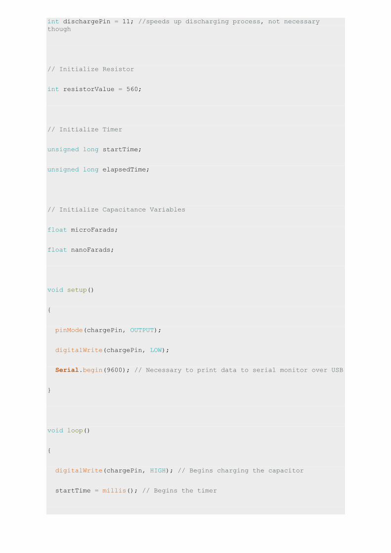
int dischargePin = 11; //speeds up discharging process, not necessary
though
// Initialize Resistor
int resistorValue = 560;
// Initialize Timer
unsigned long startTime;
unsigned long elapsedTime;
// Initialize Capacitance Variables
float microFarads;
float nanoFarads;
void setup()
{
pinMode(chargePin, OUTPUT);
digitalWrite(chargePin, LOW);
Serial.begin(9600); // Necessary to print data to serial monitor over USB
}
void loop()
{
digitalWrite(chargePin, HIGH); // Begins charging the capacitor
startTime = millis(); // Begins the timer

while(analogRead(analogPin) < 648)
{
// Does nothing until capacitor reaches 63.2% of total voltage
}
elapsedTime= millis() - startTime; // Determines how much time it took to
charge capacitor
microFarads = ((float)elapsedTime / resistorValue) * 1000;
Serial.print(elapsedTime);
Serial.print(" mS ");
if (microFarads > 1) // Determines if units should be micro or nano and
prints accordingly
{
Serial.print((long)microFarads);
Serial.println(" microFarads");
}
else
{
nanoFarads = microFarads * 1000.0;
Serial.print((long)nanoFarads);
Serial.println(" nanoFarads");
delay(500);
}
digitalWrite(chargePin, LOW); // Stops charging capacitor

pinMode(dischargePin, OUTPUT);
digitalWrite(dischargePin, LOW); // Allows capacitor to discharge
while(analogRead(analogPin) > 0)
{
// Do nothing until capacitor is discharged
}
pinMode(dischargePin, INPUT); // Prevents capacitor from discharging
}
Prototype
Source::http://www.theorycircuit.com/arduino-capacitance-meter/
3. Increasing arduino PWM pins Source:: http://www.theorycircuit.com/increasing-arduino-pwm-pins/
If we need more PWM pins in arduino board, then we can convert digital arbitrary pin to PWM pin by using wiring library (softPWM library).

By using this softPWM library we can generate up to 20 PWM channels with the single
hardware timer (Timer 2). We can create separate fade rates for on and off pulse.
Arduino Code
#include <SoftPWM.h>
void setup()
{
SoftPWMBegin();
SoftPWMSet(13, 0);
SoftPWMSetFadeTime(13, 1000, 1000);
}
void loop()
{
SoftPWMSet(13, 255);
delay(1000);
SoftPWMSet(13, 0);
delay(1000);
}
You can get softPWM library here
(Note: refer library page before using servo)

Prototype
Youtube channel::https://youtu.be/-DCM2fZVJrM
Source:: http://www.theorycircuit.com/increasing-arduino-pwm-pins/
4. Arduino Serial Command LED
Source::http://www.theorycircuit.com/arduino-serial-command-led/
In this project we used arduino serial monitor to command the LED On/Off and know the status of LED condition. By using simple measurement switch case codes and alpha numeric key we can drive digital pins of arduino.

Here we programmed arduino to turn On/Off LED that is connected in digital pin 12. Then the arduino sketch reads the status of digital pin 12 and serial prints value as either “LED is now Activated or Deactivated”. You can use this concept to control any output device connected with arduino digital pin.
Arduino Code
#define LED 12
char rxChar= 0;
void setup(){
Serial.begin(9600);
pinMode(LED, OUTPUT);
Serial.println("--- Command list: ---");
Serial.println("! -> Print this HELP");
Serial.println("o -> LED On \"activate\"");
Serial.println("f -> LED Off \"deactivate\"");
Serial.println("s -> LED \"status\"");
Serial.flush();
}
void loop(){
if (Serial.available() >0){
rxChar = Serial.read();
Serial.flush();
switch (rxChar) {

case 'o':
case 'O':
if (digitalRead(LED) == LOW){
digitalWrite(LED,HIGH);
Serial.println("LED turned On");
}
else Serial.println("LED already On!");
break;
case 'f':
case 'F':
if (digitalRead(LED) == HIGH){
digitalWrite(LED,LOW);
Serial.println("LED turned Off");
}
else Serial.println("LED already Off!");
break;
case 's':
case 'S':
if (digitalRead(LED) == HIGH)
Serial.println("LED status: On");
else Serial.println("LED status: Off");
break;

case '!':
Serial.println("--- Command list: ---");
Serial.println("! -> Print this HELP");
Serial.println("o -> LED On \"activate\"");
Serial.println("f -> LED Off \"deactivate\"");
Serial.println("s -> LED \"status\"");
break;
default:
Serial.print("'");
Serial.print((char)rxChar);
Serial.println("' is not a command!");
}
}
}

Prototype
Source::http://www.theorycircuit.com/arduino-serial-command-led/
5. Arduino serial data plotter
Source:: http://www.theorycircuit.com/arduino-serial-data-plotter/
We can create graph by using received serial data from arduino Serial Monitor. Transfer arduino or genuine serial data to computer by using processing program and get graph
result.

For to do this you need to program arduino to read any one sensor and direct the data to serial port terminal. In our case we use Force Sensitive Resistor 0.5″ as analog input sensor
and directed output to the Serial Monitor.
Arduino Code to Read Analog Sensor
void setup() {
// initialize serial communication at 9600 bits per second:
Serial.begin(9600);
}
// the loop routine runs over and over again forever:
void loop() {
// read the input on analog pin 0:
int sensorValue = analogRead(A0);
// print out the value you read:
Serial.println(sensorValue);
delay(1); // delay in between reads for stability
}
Processing Code (paste in processing IDE)
import processing.serial.*;
Serial myPort; // The serial port
int xPos = 1; // horizontal position of the graph
float inByte = 0;
void setup () {
// set the window size:
size(400, 300);
// List all the available serial ports
// if using Processing 2.1 or later, use Serial.printArray()
println(Serial.list());
// I know that the first port in the serial list on my mac

// is always my Arduino, so I open Serial.list()[0].
// Open whatever port is the one you're using.
myPort = new Serial(this, Serial.list()[0], 9600);
// don't generate a serialEvent() unless you get a newline character:
myPort.bufferUntil('\n');
// set inital background:
background(0);
}
void draw () {
// draw the line:
stroke(127, 34, 255);
line(xPos, height, xPos, height - inByte);
// at the edge of the screen, go back to the beginning:
if (xPos >= width) {
xPos = 0;
background(0);
} else {
// increment the horizontal position:
xPos++;
}
}

void serialEvent (Serial myPort) {
// get the ASCII string:
String inString = myPort.readStringUntil('\n');
if (inString != null) {
// trim off any whitespace:
inString = trim(inString);
// convert to an int and map to the screen height:
inByte = float(inString);
println(inByte);
inByte = map(inByte, 0, 1023, 0, height);
}
}
Put the program code in processing application, be careful to select console number as
shown in image, if you have more than one port available follow the order as
0 = first port (com 1)
1 = second port (com 6)
2 = third port (com 8)
3 = fourth port (com 14)
Here the port number com 1,6,… are given for examples you may have different numbers.
Look at the Serial Monitor of arduino and select the console number same as to arduino
serial monitor port number and replace the index in Serial.list()[0].

Prototype
Note: do not run serial monitor and processing at the same time, any one at a time.

Steps to Follow
Step 1: Connect any sensor with arduino board.
Step 2: Upload sensor reading sketch on arduino board (here the arduino code given for to read analog sensor connected in A0 pin), the arduino code should direct
output to serial monitor “serial.println”
Step 3: Paste the given processing code in Processing IDE, if you don’t have processing IDE
google it to get one.
Step 4: Remember to select correct console number as mentioned in this tutorial.
Step 5: Now Use only processing run option you will get graph output for sensor reading
connected with arduino.
Source:: http://www.theorycircuit.com/arduino-serial-data-plotter/
Thank you For your Interest! Hope to See you at theorycircuit.com