1.dynamic elastic and plastic deformation of double-walled cylindrical storage tanks
TRANSCRIPT
Int. J. Impact Enong Vol. 8, No. 4, pp. 341-354, 1989 0734-743X/89 $3.00 + 0.00 Printed in Great Britain Pergamon Press pie
D Y N A M I C E L A S T I C A N D P L A S T I C D E F O R M A T I O N O F D O U B L E - W A L L E D C Y L I N D R I C A L S T O R A G E T A N K S
V. K. THOMPSON* and C. RuIz Department of Engineering Science, Oxford University, Oxford, U.K.
(Received 21 September 1987; and in revised form 20 June 1989)
Snmnmry--A simple analytical method has been developed to estimate the response of cylindrical storage tanks to axisymmetric external blast loads. Included in this is the response of an inner vessel and annular insulation of the type used for storing large quantities (about 20,000 te) of liquid natural gas (LNG). Although complex, the response has simplifying features which have been fully exploited. In particular existing elastic shell solutions have been modified to model the initial response which is dominated by non-axisymmetrie elastic buckling of the thin-walled shells. Then limit analysis has been used to model the final collapse which is dominated by the formation of axial plastic hinges in the shells.
The method has been verified using physical tests on 1/150th scale models of the prototype tanks. These have been loaded with external axisymmetric blasts in a shock chamber. Special techniques were used to generate accurate model shells with very thin walls (about 50 Izm thick) by electro-deposition of copper onto removable wax cores.
1. I N T R O D U C T I O N
Large double-walled cylindrical tanks (45 m diameter by 48 m high) are used by British Gas pie to store LNG at cryogenic temperatures for matching the regular production of natural gas with peak demand. These tanks have been designed and constructed in accordance with the appropriate code of practice [1] to ensure integrity under all normal operating conditions. However, it is also of interest to examine the response of these tanks to abnormal loads which are beyond their design basis, and in this paper the effect of an axisymmetric blast on the cylindrical walls (i.e. lateral pressure) has been studied.
The tanks consist of two concentric ring-stiffened shells separated by substantial thermal insulation as shown in Fig. 1. The inner shell is cooled to below the boiling point of LNG (-162°C) and there is natural gas vapour throughout the tank interior at just above atmospheric pressure. The 2 m thick layer of annular insulation consists of expanded rock granules (trade name 'Perlite') surrounding a jacket of glass fibre. Welded-on fiat bottoms support the lower edges of the shells. Their upper edges are supported by a large primary ring girder (inner shell) and a large compression ring with an integral reinforced roof (outer shell). The shell walls increase in thickness from top to bottom.
Note that it has been assumed that the blast does not produce significant loads on the roof which would axially load the outer shell walls, and that the roof itself is sufficiently strong to resist radial deformation.
A rigorous determination of the dynamic elastic and plastic response of these tanks is a formidable task and could not be justified in view of the uncertain nature of the hypothetical loads. So emphasis has been placed on approximate estimates of the response which have been tested using scale models. In this way the accuracy of the approximate methods can be gauged and applications to full scale tanks made with some confidence.
The dynamic response of cylindrical shells to blast loads has been studied previously. However no existing approach seems suitable for the elastic and plastic response of double-walled tanks without recourse to complex numerical codes. Such codes would not be appropriate here given the nature of the hypothetical loads. In ref. I-2] single-walled cylinders were tested with external lateral blasts and their dynamic buckling response was
*V. K. Thompson is now employed by the UKAEA, Culham Laboratory, Abingdon, Oxfordshire, OXI4 3DB, U.K.
341
342 V.K. THOMPSON and C. RuIz
o Io i I
oLe ( m )
, . =-~ .-:~
i i .ill i i i i
FIG. 1. LNG storage tank.
2O i
found to be in good agreement with analytical solutions based on the Donnell shell equations. These equations form the basis of the elastic response derived below and the method of presenting the results on pressure-impulse diagrams used in [2] has been adopted here.
2. A N A L Y T I C A L M E T H O D S
2.1. General behaviour
There are certain features of these tanks and their anticipated response to blast loads which suggest suitable simplifications namely:
• The shells have very large diameter to wall thickness ratios (~ 4000:1) and so under external pressure elastic buckling occurs well before any yielding.
• Deformation occurs into circumferential waves with a moderately large number of lobes (> 10). Firstly, this allows simplified shell equations to be used in the elastic regime. Secondly in the plastic regime it implies that the energy dissipation associated with bending of axial hinges dominates the response.
• The annular insulation is weak in shear and hoop distortion (relative to the shells), and so a purely radial stiffness term is adequate for this component.
• The supports at the shell boundaries can be reasonably approximated by pinned joints. • The shells are made from ductile materials [mild steel (outer shell) and 9% nickel steel
or aluminium alloy (inner shell)] with a large plastic range before failure. This suggests the use of limit analysis in the plastic regime.
Armed with this information and following observations on the static response of scale models the response of these tanks following a large blast is expected to result in the following sequence of events.
1. Axisymmctric deformation of the outer shell. For most cases of interest here the blast durations are long compared to the axisymmetric 'breathing' mode and hence this mode will be quasi-static.
2. Elastic buckling of the outer ~hell into circumferential waves. This will cause loads to be transferred via the insulation onto the inner shell and cause it to deform correspondingly.
3. Plastic hinges form on the outer shell. 5. The outer shell collapses plastically (note that stages 4 and 5 may occur in reverse
order). 6. The inner shell collapses plastically. 6. The outer shell partly springs back due to residual loads in the insulation after the
blast has passed.
Deformation of double-walled cylindrical tanks 343
This sequence has been analysed by assuming a limited degree of freedom deformation. The number of circumferential waves, n, is assumed a priori together with separate deformation modes appropriate to the elastic and plastic phases. Two parameters (i.e. one for each shell) then characterize the deformation, e.g. the maximum radial deflection, and reference blasts can be analysed. By repeating this process for other values of n the dominant mode can be identified. This assumes that superposition is possible which is invalid in the non-linear plastic regime. However this is justified here on the basis of experience with model tests and on the analytical results described below. Both indicate that for a given tank and blast load the response is well defined within a narrow range for n.
2.2. Elast ic s tage
Here a total radial deflection, w + 3, of the following form is assumed for each shell:
w = Wo + wn cos(n0) s i n ( n x / L ) ~ = 3, cos (n0) s i n ( n x / L ) .
The unloaded deflection 6 represents initial imperfections. The shell length is L and x, 0 are the axial and circumferential co-ordinates respectively. The radial pressure p = Po + P, cos(n0) is taken to include both the effects of the blast and the insulation deformation. The equation of motion for flexural mode n is given by:
pha d2wn p~a (Po -- Pc.)w. = - - - + Po~.. n 2 dt 2 n 2
Here p is the shell material density, h is the shell wall thickness, a is the shell radius, t is time, Pc, = Dn2/a3 + (1 - v2)C(rca/L)+/(anr) , D = Eh3/12(1 - v2), C = Eh/(1 - v2), v is Pois- son's ratio and E is Young's modulus.
This equation was derived in ref. [3]. It is based on the Donnell shell equations, decoupled to give this single equation, with a radial inertia term added. It assumes that the 'breathing' mode (n = 0) is quasi-static. The derivation applies strictly to isotropic shells of constant thickness. Hence the ring stiffening has been approximated here by adding a term, E ~, I , / L , where Jr, is the ring second moment of area, to the flexural stiffness D. This smears the discrete stiffening of the rings over the whole axial length and is valid here for global buckling where displacements vary smoothly over this length. Local buckling of the panels between the rings can be considered separately if required, but this is of secondary importance here since the response and residual damage are dominated by global deformation. It is noted that increasing D effectively adds axial as well as circumferential stiffening but here circumferential curvature dominates and negligible error is introduced. The variation of shell wall thickness could not be accommodated and so the average value was used.
The insulation is assumed to be an elastic medium thus pn = k(w~ - w',), where k is the insulation stiffness and (') refers to the inner shell. Hence the elastic motion, for n > 0, is given by the solution to:
pha d2wn ka , n2 d t ~ - (Po - pc.)w. + po6. + - ~ (w~ - w. ) outer shell
p'h'a' d2w'. ka' n2 d t ~ - p'c.w'. - ~ (w'. - w. ) inner shell.
In this form the response can be represented by the mechanical analogue shown in Fig. 2. The elastic phase will end when the bending strain in the outer fibres of the rings, eb,,
reaches the yield strain of the ring material, try,/E. Here
d t~2w dn 2 8b, = 2a 2 t30---- 5 _ 2a 2 w,.
The ring is assumed to be symmetrically located on the shell surface and to have a total
344 V.K. THOMPSON and C. Rulz
[_ Outer sheLL InsuLation r j _
Inner sheLL
T -I
R
FIG. 2. Mechanical analogue.
radial depth d. It follows that yielding occurs when
2a2tyyr
wn = n 2 E d •
The equations above, without the inertia terms, were derived in [4] for the case wn or w' n = 0, and used to estimate the buckling pressures of laterally loaded double-walled tanks. Both local and global buckling were examined and the results were bench-marked against numerical models based on the Finite Difference code BOSOR4 [5], in which the discrete stiffening rings and the wall thickness variations could be accurately represented. Although the analytical results tended to be conservative due to the analytical assumptions of pinned boundaries on the panels and constant wall thickness (the panel average was taken), the two methods agreed reasonably well.
2.3. C o l l a p s e d s t a t e s
The plastic stage has been analysed by considering the transition from plastic hinge formation at the end of the elastic stage into a fully collapsed state, using limit analysis. The transition from first yielding of the outer fibres to fully plastic hinges is thus ignored but justified as this occupies only a small fraction of the total collapse deformation. However, the initial fully elastic stage has a crucial bearing on the plastic response as (a) it determines the initial position of the plastic hinges and (b) kinetic energy accumulated during the elastic stage is dissipated during the plastic stage. This is considered later.
The limit analysis has been simplified by calculating the plastic dissipation term from the total plastic energy associated with fully collapsed shells. This approach overcomes the major difficulty of characterising a continuous mode of deformation for cylindrical shells collapsing non-axisymmetrically and essentially reduces the approach to the 'mode' solution method described in ref. [6]. This problem is common to many shell structures which, unlike plates and beams, cannot deform into a collapsed state purely by bending. Membrane deformations must occur at intermediate stages and these would give unreal- istically large dissipations in a limit analysis (which assumes ideal rigid-plastic behaviour). In real shell structures these temporary membrane deformations may be accommodated within the elastic range even though the bending distortions are predominantly plastic. Thin shells can thus collapse by 'jumping' between two end states which are relatively free of membrane stress via intermediate stages where no net membrane dissipation occurs.
Yoshimura [7] studied this in connection with axial collapse of cylindrical shells. The collapsed state consisted of a polyhedral surface of identical triangles as shown in Fig. 3(a). For collapse due to lateral pressure the initial elastic stage has only one half-wave in the axial direction and the collapsed state shown in Fig. 3(b) would be a possibility.
A consequence of the arguments above is that the collapsed state must be inextensional when compared with the original cylindrical surface. A necessary condition for this is that
Deformation of double-walled cylindrical tanks 345
(a) Yoshimura axiat (b) Laterat
FIG. 3. Collapsed states.
K' A'
FIG. 4. Collapsed state with reverse curvature.
rIL/2. The axial mismatch 6
given by Wk, where,
the Gaussian curvature should be invariant 18]. The Gaussian curvature of a cylinder is zero, hence the collapsed state should be constructed from zero Gaussian curvature surfaces, i.e. flat plates, cylindrical panels (of any radius) or conical panels. This can be seen in the alternative lateral collapsed state shown in Fig. 4. This state consists of cylindrical panels with rectangular boundaries (CDEF) and triangular boundaries (ACF) which have opposite curvature to the original form. The triangular panels (JCA) are undeformed and so, in contrast to the state in Fig. 3(b), the ends remain circular. This is consistent with the boundary conditions imposed on the tank shells. Note however that this mode is axially incompatible as meridians such as AHIA' must shorten relative to those such as KCDK' but this may be accommodated by a series of kinks as shown at D.
The mode is defined by the number of lobes, n, and the axial length of the end-panels, 2a27t 4
and the dissipation associated with these kinks is ~iLn 4
h 2 W k ,~ try, ~ 2ha. 8Ok.
Here try, is the yield stress of the shell material and Ok is the fold angle of the kink hinges (see inset in Fig. 4). If b is the central axial length of the kink before collapsing then cos (Ok)= 1 --6/2b. Clearly b must be larger than 6/2 but not too large as to impinge on the global collapse pattern. It is assumed that b = 6 and thus
16 ~ 2 a .
3 t 4
346 V.K. THOMPSON and C. RuIz
I I l l l r
FIG. 5. Prismatic collapse mode.
The dissipation in the rest of the shell is given by Ws, where
h 2//8a2~ 3 r])/
Here Y. Zn, is the plastic modulus of the stiffening rings summed over the shell length. Note that Ws includes dissipation from curvature reversal of panels such as ACF in addition to dissipation at the hinges.
The mean collapse pressure of the shell, Pn,, is given by
p~. = (W~ + W~)/AV~.
Here the volume change at collapse A Vc = ( 1 - ~ ) j \ n / The end-length parameter
r/can be found by minimizing Ppn with respect to r/. In static collapse, for the shells of interest here, n is typically less than 10 and the kink term is significant. However in dynamic cases where n is typically much larger the contributions from the kinks, and from the end regions, can be neglected and
6n2 ay s~-+ay , P pn "~ ~
2.4. Dynamic plastic response
With the simplifications introduced above the dynamic plastic response of the shell is similar to that of the arch structure shown in Fig. 5. The response is obtained from the power balance
dAV d dEk p - - - (w,+ Wk)+- -
dt dt dt
Here Ek is the shell kinetic energy and A V the instantaneous change in shell volume. With the assumption that W~ + Wk is linearly proportional to AV this equation reduces to
dE k dAV
d t - (p - pp') d ~ -
fo fo 2~pha(dw~2 + k f2~ HereEk=nL ~ - - \ ~ / d0, A V = - n L awdOandp=po ~ n j o (w , -w ' , )dO.A
reasonable approximation to the deformation mode shown in Fig. 5 is given by w = - w n cos(nO~2) and hence the equations of motion in the fully plastic regime are:
d2wn 4 a ( 2k ) - Po - Pn. + -~- (w'n - w~) outer shell pha ~ ~t
d,w, ( )) ! f p'h' a' ~ _ 4a' -Pp~ _ __2k (wn - w, inner shell.
dt 2 ~ rt
Deformation of double-walled cylindrical tanks 347
1200
IO00
800
600
60
40
20
ColLapse
2400
2 2 0 0
Outer 2 0 0 0 shel l
1800
1600
PuLse duration ( mse¢ ) - = aO .~ 1400
7.0 80
3.0 1.7
I I I IO 20 30
n
FIG. 6. Analytical results.
60
40
20
Collapse
Inner shell
7.0
Yield
3.0 1.7
I I I0 20
n
The transition from the elastic mode to the plastic mode, as assumed here, involves a discontinuity in deformation but the error associated with this can be minimized by minimizing a parameter A where
A - - } - (v . - vb) ~ d s .
This parameter characterizes the difference in the modes [9]. The integration is over the surface area, s, of the shell which has a specific mass, m, and v. and vb are the velocity distributions in the two modes. Here:
C'.~" I [d~.~ dw., [nO~ 2 A = 2nphaL / - / - - c o s ( n 0 ) - , / _ ~ l / dO.
Subscripts e and p denote elastic and plastic stages respectively. Note that a prismatic form has been chosen for W.e in order to be consistent with the plastic stage. Minimizing
A with respect to dw"w gives the optimum condition for the start of the plastic solution, dt
i.e. dw, p _ 4 dw,e dt 3n dt
2.5. Example of the analytical results
The equations of motion above have been integrated numerically for a number of reference cases. For a given blast the time integration is done for each value of n, and the resulting peak displacements normalized to the initial imperfections, w./6., for the case of a double-walled model tank, are shown in Fig. 6. Note the discontinuity in the vertical scale. A centrally peaked triangular pressure waveform was used with a peak over-pressure of 1200 N /m 2. The duration was varied as shown to find the limiting cases where yielding and full collapse of the shells occurred. The values of these thresholds were assumed to be independent of n, for reasons which will be described below.
Note how peaked the results are in the plastic regime--the dominant modes being
348 V.K. THOMPSON and C. RuIz
confined to within about 3 wavenumbers of the actual peak. This gives some justification to the use of a limited degree of freedom analysis as adopted here.
3. C O M P A R I S O N W I T H E X P E R I M E N T A L R E S U L T S
3.1. Test procedure It is clear from the above that major approximations were necessary to facilitate analytical
solutions and so physical models have been constructed and tested as means of verification. Exact scaling of the prototype tanks was not practical so the model results cannot be used to predict the response of full scale tanks directly. Nevertheless it is anticipated that the failure mode is the same in both cases (i.e. elastic buckling followed by plastic collapse) and hence the model results should provide useful representative test cases to verify the analytical methods. The scale chosen was 1/150 and to achieve similarity of inertia effects the time scale for the models was similarly scaled, i.e. a typical model blast duration would be ,~ 3 msec.
The model shells were manufactured by electro-deposition of copper onto removable wax cores which were cast using high precision moulds. In this way thin-walled shells with the required accuracy could be generated from a material having uniform mechanical properties free from residual stresses. It also allowed integral ring stiffeners to be included and the variable wall thickness of the prototype tank shells to be accurately scaled (although in the analytical method described above this variation could not be modelled and the average wall thicknesses were used). The method of manufacture is described in detail in [10] and the model shells are featured in Fig. 7.
A series of shells were manufactured (11 outer and 10 inner shells) to develop the technique and to provide sufficient shells for static and dynamic tests. The static tests are described in [11].
Dynamic loading was achieved by mounting the models in the close-fitting shock tube shown in Fig. 8. The models were sealed to end plates to prevent internal pressurization and these plates were supported by a rigid column to prevent axial loading of the shells. The shock tube was connected to a driver chamber via bursting diaphragms of Melinex. Several driver chambers of differing volume were used and the driver pressure could be varied using diaphragms of different thicknesses. This allowed a range of blasts to be generated with over-pressures up to 25 kN/m 2 and durations in the range 0.5-10 msec. As the gas from the driver chamber discharges into the shock tube it pressurizes the model before escaping via an exhaust gap as shown. The decay portion of the blast duration could be controlled by varying this gap. The pressure was found to be reasonably uniform over the model surface and a typical time profile is shown in Fig. 9. The blasts were
Rings
boy h L boy h L n ° (ram) (rnm) _ ~ ~ n ° (rnrn) (ram)
0.05 15
3 4 5 6 7
8 0.06 20
9 0-07 30
10 0.08 32
11 0'1 67
i
INNER SHELL
FIG. 7. Model tank.
1 005 43
2 ,' 50
3 0"075 72
j 4 Ol 11o
OUTER SHELL
Deformation of double-walled cylindrical tanks 349
E x h a o s , "
/ / × / / N x / /
Pertite --------" x / /
× / / × / /
Model ~ ~ // s hells ~ ~ / /
/ / / / / / / / / /
Pressure <~ , roosd, ,cer - . - - .
Sponge damper .~~.. ~..~
Pulsed .~.~////////~ pressure chomber ~xx"~_~__~
Compressed air
I " ~ ~ Bursting
~ f ~ d i a p h r a g m
_ Driver ~ chamber L'\ \ \ \ \N1 J
FIG. 8. Dynamic test r ig.
I IOkN/m2 Pressure
1_ _1
1.3 msec FIG. 9. Typical blast wave.
characterized by identifying their positive duration (i.e. the time to first occurrence of a definite negative pressure) and pressure impulse. The latter was found by integrating the area under the pressure time plot over the positive duration.
To minimize the number of shells required each model tank was tested several times. Initially several blasts of gradually larger over-pressure and duration were used to find the yielding threshold where residual damage was just visible. The models were removed from the shock tube after each blast and examined. Measurements were also made during the
350 V . K . THOMPSON a n d C. R u ] z
ca
E z
P
P o .
Q
0
n=25 _ 3s l -21 Test I
/ I / moged ~ Experimental /~1 o ~ / ~ o m a g e d / results
--tu / /1"14 ~ Y i e L d threshold I
/ I / 3riti0ot .eve.umber ,
~ I I I I I0 20 30 40
Imputse ( Ns/m 2)
E
z
o
P
t -
O @
2B~ rrr~
:::!
10
14
i0
Test 2
° ~ n = 13_18~ °
I I ~ I 2O 30 6O ImpuLse ( N $ / m z )
FIG. 10. Results for outer shell (tests 1 and 2).
I 7o
blasts with strain gauges and any residual strain indicating yielding was noted. Following detection of the yield threshold two or three much larger blasts were used to examine the behaviour in the plastic regime. Damage corresponding to both local and global buckling was observed but the latter was clearly dominant and the discussion below refers to this.
3.2. Outer shell tests
Two outer shells were tested initially in isolation before embarking on the double-walled models as this allowed the effect of the insulation to be isolated. The results of this are summarized in Fig. 10. These are plots of mean over-pressure against pressure impulse on which the test results have been identified by points with (x) if no damage resulted and by (0) if visible damage was found. In the later case the number of lobes has been identified. The no-daraage points have been grouped together by forming a polygon through the points furthest from the origin and extending to tbe axes at constant pressure and i m ~ as shown by the hatched boundaries in Fig. 10.
Also shown arc the yield threshold and plastic collalzz lines obtained from the analytical methods above. These were derived by numerioally ~ t i n 8 the equations of motion for a series of pressure and impulse combinations. Within each combination a farther series of integrations was used to identify the critical wavenumber (i.e. that which gave the largest
Deformation of double-walled cylindrical tanks 351
i?i ̧ ̧ i
FXG. 11. Outer shell after testing.
bending strain or the mode closest to collapse). The results are summarized by pressure- impulse characteristics along which the critical wavenumber varies as shown in Fig. 10. Here the pressure pulses have been approximated by a centrally peaked triangular waveform and hence the mean pressure is half the peak value. Rectangular waveforms give similar results.
The analytical solutions are obtained in the form of an amplification of initial imperfections for each wavenumber, i.e. Wn/6n. It was only practical to measure the initial imperfection in the elliptic mode (n = 2). However 6n clearly falls with increasing n, and the solution is not particularly sensitive to the actual values of 6n, so it was assumed that
6n n2= constant. Hence the reference deformations are given by why_ a2tryr for the yield 6~ 262Ed
threshold and w~ lz2a - - - for full collapse. Here a=0.150m, try,= 100 MN/m 2, trys= 6n 462
150MN/m 2, 62=0.3mm, E = l l 0 G N / m 2, d=0 .71mm and hence w~y/6~50 and w~/6~ ~, 1240.
The correspondence between the test results and the analytical predictions can be gauged by noting that all the tests without damage lie on the correct side of the yield threshold. A quantitative comparison in the plastic region is difficult to make unless the result happens to coincide with the collapse line. However the results seem reasonable since the final blast in test 1 caused a 'near collapse' in the context of the mode shown in Fig. 4 with 25 lobes. A post-test photograph of this shell is shown in Fig. 11. The 25 lobes correspond with a range of 21-38 expected from a comparison with the yield threshold and plastic collapse lines at similar pressures. Reasonable agreement also occurred with the first plastic blast in test 2 where, because of the lower pressure used, the number of lobes was lower, i.e. 18 observed and 12-20 predicted.
Note the line representing the limit of validity of the assumption that the breathing mode is quasi-static (line BME in Fig. 10). As all the results lie below this line the assumption is valid.
It is interesting to note that with large numbers of lobes the depressions in the shells are very shallow (~ 3 mm for collapse at n = 25) and the damaged shells effectively become corrugated structures which appear stronger than the original undamaged plain cylinders. This was demonstrated with two further blasts in test 2 beyond the collapse line. The first of these resulted in a set of fully collapsed lobes with n = 13 superimposed on the existing
352 v. K. THOMPSON and C. Rulz
partially collapsed lobes with n = 18. The final very large blast caused no further deformation and the shell was corrugated but otherwise undamaged.
3.3. Double-walled tank tests
A similar procedure was used here and the inspection extended to reveal any residual damage to the inner shell by viewing it with a dental mirror through an access port in the top cover plate. Now four analytical reference characteristics were obtained corresponding to yielding and collapse of each shell and the test results were divided into those with residual damage in neither shell ( x ) , in the outer shell only (O), or in both shells (U]) as shown in Fig. 12. Again two tank models were tested. The insulation used in the tanks was pure Perlite and a stiffness of 3.04 kN/m was used in the analytical method corresponding to a modulus of 225 kN/m 2 which had been measured in dynamic tests on Perlite samples.
The experimental results with no damage are again grouped as predicted except for a small excursion into the post-yield region for test 4. However the post-yield blast results in test 3 are on the wrong side of the corresponding thresholds although the deviations are not large and may be a result of an accumulation of small damage following the rather large number of earlier 'no damage' blasts. The final blast in test 3 resulted in partial
2 0
N E Z .1¢
.=. ~, ,0 Q. t- O 0
Test 3 - ~
o_ = .~- ~ o c o •
I ~,/ 27 .~c ~ I®. / \ \ ~ e x p e r i m e n t o t ~ o Outer domoge i , u ~ nf24(outer} \ \ ~ resu t t s I a Id / - -n f21 ( inner ) _ ~ o | Both domoged
i °k t \ \
×xx × x >,~ 15
x x
x I ~ I I I I I I0 20 30 4 0 50 60
ImpuLse ( N s / m 2 )
A
E Z
io = P 0.
e= 0 0
37-~ /
7 x / x
// x
xXx x
/
I [] ~\ Test 4
11'2 I I I I I I I0 20 30 40 50 60
I m p u t N ( N s / m z )
FIG. 12. Resu l t s for d o u b l e - w a l l e d t a n k s (tests 3 a n d 4) .
Deformation of double-walled cylindrical tanks 353
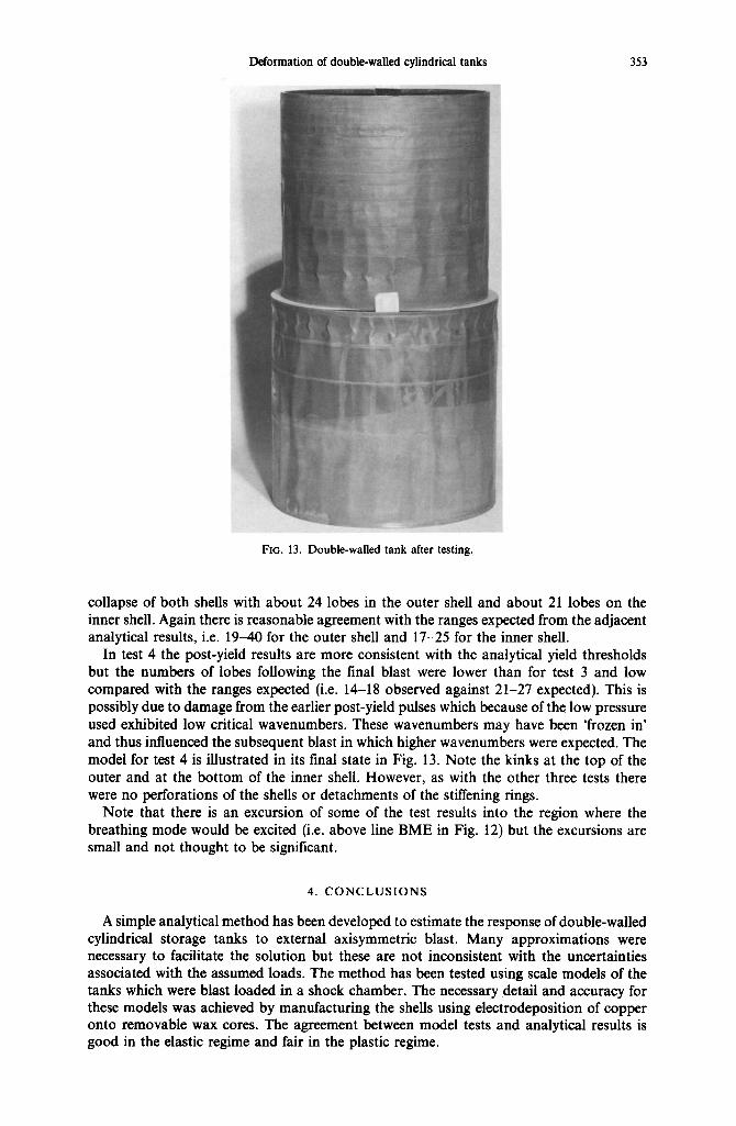
FIG. 13. Double-walled tank after testing.
collapse of both shells with about 24 lobes in the outer shell and about 21 lobes on the inner shell. Again there is reasonable agreement with the ranges expected from the adjacent analytical results, i.e. 19-40 for the outer shell and 17-25 for the inner shell.
In test 4 the post-yield results are more consistent with the analytical yield thresholds but the numbers of lobes following the final blast were lower than for test 3 and low compared with the ranges expected (i.e. 14-18 observed against 21-27 expected). This is possibly due to damage from the earlier post-yield pulses which because of the low pressure used exhibited low critical wavenumbers. These wavenumbers may have been 'frozen in' and thus influenced the subsequent blast in which higher wavenumbers were expected. The model for test 4 is illustrated in its final state in Fig. 13. Note the kinks at the top of the outer and at the bottom of the inner shell. However, as with the other three tests there were no perforations of the shells or detachments of the stiffening rings.
Note that there is an excursion of some of the test results into the region where the breathing mode would be excited (i.e. above line BME in Fig. 12) but the excursions are small and not thought to be significant.
4. CONCLUSIONS
A simple analytical method has been developed to estimate the response of double-walled cylindrical storage tanks to external axisymmetric blast. Many approximations were necessary to facilitate the solution but these are not inconsistent with the uncertainties associated with the assumed loads. The method has been tested using scale models of the tanks which were blast loaded in a shock chamber. The necessary detail and accuracy for these models was achieved by manufacturing the shells using electrodeposition of copper onto removable wax cores. The agreement between model tests and analytical results is good in the elastic regime and fair in the plastic regime.
354 V. K. THOMPSON and C. Ru~z
Acknowledgements--The authors wish to thank Mr P. Hardy from Oxford University for his technical support and Mr D. Neville from British Gas plc for his help and co-operation, and British Gas plc for their permission to publish this paper.
R E F E R E N C E S
1. Recommended Rules for Design and Construction of Large Welded Low Pressure Storage Tanks. API standard 620, American Petroleum Institute, 6th edition (1978).
2. D. L. ANDERSON and H. E. LINDBERG, Dynamic pulse buckling of cylindrical shells under transient lateral pressures. AIAA J. 6 (4) (1968).
3. C. RuIz, E. DALVATORELLI-D'ANGELO and V. K. THOMPSON, Elastic response of thin-walled cylindrical vessels to blast loading. Comput. Struct., to be published.
4. V. K. THOr, n'SON, Elastic buckling of double-walled cylindrical storage tanks--numerical and analytical estimates. Comput. Struct. 3, 23 (1986).
5. D. BUSHNELL, Buckling of elastic-plastic shells of revolution with discrete elastic-plastic stiffeners. Int. J. Solids Struct. 12 (1976).
6. J. B. MARTIN and P. S. SYMONDS, Mode approximations for impulsively loaded rigid plastic structures. J. Eng. Mech. Div. Proc. ASCE EM5 (1966).
7. Y. YOSHIMURA, On the mechanism of buckling of a circular cylindrical shell under axial compression. Report of the Institute of Science and Technology of the University of Tokyo, Vol. 5 (1951).
8. C. R. CALLADINE, The static geometric analogy in the equations of thin shell structures. Math. Proc. Camb. Phil. Soc. 82, 235 (1977).
9. P. S. SYMONDS, Finite elastic and plastic deformations of pulse loaded structures by an extended mode technique. Int. J. Mech. Sci. 22 (1980).
10. C. RuIz, V. K. THOMPSON and P. R. MURRAY, Modelling of thin-walled shells for buckling investigations by electroplating Part I--Manufacture of models. Exp. Techniques 11 (11), 22-25 (1987).
11. C. Ru1z and V. K. THOMPSON, Modelling of thin-walled shells for buckling investigations by electroplating Part II--Testing of models. Exp. Techniques 11 (12), 19-23 (1987).