1mrk500079-men a en builders guide ied 670 products
TRANSCRIPT

Builder’s guideIED 670 products
Innovation from ABB


© Copyright 2006 ABB. All rights reserved.
Builder's guideIED 670 products
About this manualDocument No: 1MRK 500 079-MEN
Issued: April 2006Revision: A

COPYRIGHT
WE RESERVE ALL RIGHTS TO THIS DOCUMENT, EVEN IN THE EVENT THAT A PATENT IS ISSUED AND A DIFFERENT COMMERCIAL PROPRIETARY RIGHT IS REGISTERED. IMPROPER USE, IN PARTICULAR REPRODUCTION AND DISSEMINATION TO THIRD PARTIES, IS NOT PERMITTED.
THIS DOCUMENT HAS BEEN CAREFULLY CHECKED. HOWEVER, IN CASE ANY ERRORS ARE DETECTED, THE READER IS KINDLY REQUESTED TO NOTIFY THE MANUFACTURER AT THE ADDRESS BELOW.
THE DATA CONTAINED IN THIS MANUAL IS INTENDED SOLELY FOR THE CONCEPT OR PRODUCT DESCRIPTION AND IS NOT TO BE DEEMED TO BE A STATEMENT OF GUARAN-TEED PROPERTIES. IN THE INTERESTS OF OUR CUSTOMERS, WE CONSTANTLY SEEK TO ENSURE THAT OUR PRODUCTS ARE DEVELOPED TO THE LATEST TECHNOLOGICAL STAN-DARDS. AS A RESULT, IT IS POSSIBLE THAT THERE MAY BE SOME DIFFERENCES BETWEEN THE HW/SW PRODUCT AND THIS INFORMATION PRODUCT.
Manufacturer:
ABB Power Technologies ABSubstation Automation ProductsSE-721 59 VästeråsSwedenTelephone: +46 (0) 21 34 20 00Facsimile: +46 (0) 21 14 69 18www.abb.com/substationautomation

Contents
PageChapter
Chapter 1 Introduction ..................................................................... 1
Introduction to Builder's guide.............................................................. 2About the builder's guide ................................................................ 2Intended audience .......................................................................... 2Related documents......................................................................... 2Revision notes ................................................................................ 5
Chapter 2 Safety information........................................................... 7
Safety and ESD information ................................................................ 8Identification of the labels on the relays and relay assemblies....... 8ESD information ............................................................................. 8
Chapter 3 Mounting methods and details .................................... 11
Overview............................................................................................ 12IED sizes and dimensions ................................................................. 14
Case without rear cover................................................................ 15Case with rear cover..................................................................... 16
Flush mounting .................................................................................. 17Overview....................................................................................... 17Mounting procedure for flush mounting ........................................ 18Ordering details ............................................................................ 19Flush mounting dimensions.......................................................... 20
19” panel rack mounting .................................................................... 21Overview....................................................................................... 21Mounting procedure for 19” panel rack mounting......................... 22Ordering details ............................................................................ 23
Wall mounting .................................................................................... 24Overview....................................................................................... 24Mounting procedure for wall mounting.......................................... 25How to reach the rear side of the IED........................................... 26Ordering details ............................................................................ 27Wall mounting dimensions............................................................ 28
Side-by-side 19” rack mounting ......................................................... 29Overview....................................................................................... 29Mounting procedure for side-by-side rack mounting..................... 29Ordering details ............................................................................ 30IED 670 mounted with a RHGS6 case ......................................... 30
Side-by-side flush mounting .............................................................. 32Overview....................................................................................... 32Mounting procedure for side-by-side flush mounting.................... 33Ordering details ............................................................................ 34Side-by-side flush mounting dimensions ...................................... 34

Contents
Chapter 4 Electrical connections .................................................. 37
Connecting to protective earth ........................................................... 38Connecting the power supply module................................................ 39Connecting to CT and VT circuits ...................................................... 40Connecting the binary input and output signals ................................. 41Making the screen connection ........................................................... 44
Chapter 5 Optical connections ...................................................... 45
Overview............................................................................................ 46Connecting station communication interfaces (OEM and SLM) ........ 47Connecting remote communication interfaces (LDCM) ..................... 48
Chapter 6 GPS antenna Installation .............................................. 49
Overview............................................................................................ 50Installing the GPS antenna ................................................................ 51
Antenna installation ...................................................................... 51Electrical installation ..................................................................... 52
Ordering details ................................................................................. 53
Chapter 7 IED connectors .............................................................. 55
Overview............................................................................................ 56Front side connectors ........................................................................ 57Rear side connectors ......................................................................... 58Connection diagrams......................................................................... 61
Chapter 8 Test switch modules ..................................................... 65
Overview............................................................................................ 66Ordering details ................................................................................. 69Test switch configurations.................................................................. 714U 19” rack mounting of test switches............................................... 74
Chapter 9 Mounting in cubicles..................................................... 77
Overview............................................................................................ 78Requirements .................................................................................... 79
Degrees of protection ................................................................... 79Identification examples using the IP code ............................... 79
Environmental aspects ................................................................. 80Earthquake protection................................................................... 80Power losses ................................................................................ 80

Contents
Ambient temperature .................................................................... 82Maximum permissible ambient temperature............................ 82Permissible temperature increase ........................................... 82Permissible power losses ........................................................ 83Temperature rise ..................................................................... 83Self-ventilated design of the cubicle ........................................ 86
Earth connection................................................................................ 88
Chapter 10 Glossary......................................................................... 91
Glossary............................................................................................. 92

Contents

1
About this chapter Chapter 1Introduction
Chapter 1 Introduction
About this chapterThis chapter explains concepts and conventions used in this manual and provides information necessary to understand the contents of the manual.

2
Introduction to Builder's guide Chapter 1Introduction
1 Introduction to Builder's guide
1.1 About the builder's guideThe builder's guide contains the following chapters:
• The chapter “Safety information” describes the safety information. Warning signs are presented which urge the user to be careful during certain operations in order to avoid injuries to humans or damage to equipment.
• The chapter “Mounting methods and details” describes different mounting meth-ods and details.
• The chapter “Electrical connections” describes how to make the electrical con-nections
• The chapter “Optical connections” describes how to make the optical connec-tions
• The chapter “GPS antenna installation” describes how to install the GPS antenna.• The chapter “IED connectors” describes the type and designation of connectors
on the IED.• The chapter “Test switch modules” describes the different test switch modules
with configurations.• The chapter “Mounting in cubicles” describes the mounting of units in cubicles.• The chapter “Glossary” is a list of terms, acronyms and abbreviations used in
ABB technical documentation.
1.2 Intended audienceThis guide is intended for system integrators.
1.3 Related documents
Documents related to RED 670 Identity number
Operator’s manual 1MRK 505 133-UEN
Installation and commissioning manual 1MRK 505 134-UEN
Technical reference manual 1MRK 505 132-UEN
Application manual 1MRK 505 135-UEN
Buyer’s guide 1MRK 505 164-BEN
Connection diagram, Single breaker arr. Three phase tripping arr. 1MRK 002 801-BA
Connection diagram, Single breaker arr. Single phase tripping arr. 1MRK 002 801-CA
Connection diagram, Multi breaker arr. Three phase tripping arr. 1MRK 002 801-DA
Connection diagram, Multi breaker arr. Single phase tripping arr. 1MRK 002 801-EA

3
Introduction to Builder's guide Chapter 1Introduction
Configuration diagram A, Single breaker with single or double busbars 1MRK 004 500-82
Configuration diagram B, Single breakers with single or double busbars 1MRK 004 500-83
Configuration diagram C, Multi breakers such as 1 1/2 or ring busbar arr. 1MRK 004 500-84
Configuration diagram D, Multi breakers such as 1 1/2 or ring busbar arr. 1MRK 004 500-85
Setting example 1, 230 kV Short cable line with 1 1/2 CB arr. 1MRK 505 175-WEN
Documents related to REL 670 Identity number
Operator’s manual 1MRK 505 233-UEN
Installation and commissioning manual 1MRK 506 234-UEN
Technical reference manual 1MRK 506 232-UEN
Application manual 1MRK 505 235-UEN
Buyer’s guide 1MRK 506 264-BEN
Connection diagram, Single breaker arr. Three phase tripping arr. 1MRK 002 801-BA
Connection diagram, Single breaker arr. Single phase tripping arr. 1MRK 002 801-CA
Connection diagram, Multi breaker arr. Three phase tripping arr. 1MRK 002 801-DA
Connection diagram, Multi breaker arr. Single phase tripping arr. 1MRK 002 801-EA
Configuration diagram A, Single breaker with single or double busbar 1MRK 004 500-86
Configuration diagram B, Single breaker with single or double busbar 1MRK 004 500-87
Configuration diagram C, Multi breaker such as 1 1/2 or ring busbar arr. 1MRK 004 500-88
Configuration diagram D, Multi breaker such as 1 1/2 or ring busbar arr. 1MRK 004 500-89
Setting example 1, 400 kV Long overhead power line with 1 1/2 CB arr. 1MRK 506 267-WEN
Setting example 2, 230 kV Extremely long overhead power line, double bus, single CB arr.
1MRK 506 268-WEN
Setting example 3, 132 kV Short overhead power line, double bus, single CB arr.
1MRK 506 269-WEN
Documents related to REC 670 Identity number
Operator’s manual 1MRK 511 150-UEN
Installation and commissioning manual 1MRK 511 151-UEN
Technical reference manual 1MRK 511 149-UEN
Application manual 1MRK 511 152-UEN
Buyer’s guide 1MRK 511 176-BEN
Connection diagram, Single breaker 1MRK 002 801-FA
Documents related to RED 670 Identity number

4
Introduction to Builder's guide Chapter 1Introduction
Connection diagram, Double breaker 1MRK 002 801-MA
Connection diagram, 1 1/2 CB 1MRK 002 801-NA
Configuration diagram A, Single breaker arr. with single or double busbar 1MRK 004 500-90
Configuration diagram B, Double breaker arrangements 1MRK 004 500-91
Configuration diagram C, 1 1/2 breaker arr. for a full bay 1MRK 004 500-92
Documents related to RET 670 Identity number
Operator’s manual 1MRK 504 049-UEN
Installation and commissioning manual 1MRK 504 050-UEN
Technical reference manual 1MRK 504 048-UEN
Application manual 1MRK 504 051-UEN
Buyer’s guide 1MRK 504 080-BEN
Connection diagram, Two winding transf. Single breaker arrangements 1MRK 002 801-LA
Connection diagram, Two winding transf. Multi breaker arrangements 1MRK 002 801-HA
Connection diagram, Three winding transf. Single breaker arrangements 1MRK 002 801-KA
Connection diagram, Three winding transf. Multi breaker arrangements 1MRK 002 801-GA
Configuration diagram A, Two winding transf. with single or double busbar but with a single breaker arr. on both sides
1MRK 004 500-93
Configuration diagram B, Two winding transf. in multi breaker arr. on one or both sides
1MRK 004 500-94
Configuration diagram C, Three winding transf. with single or double busbar but with a single breaker arr. on both sides
1MRK 004 500-95
Configuration diagram D, Two winding transf. in multi breaker arr. on one or both sides
1MRK 004 500-96
Setting example 1, 400/230 kV 500 MVA Transformer, YNyn connected 1MRK 504 083-WEN
Setting example 2, 132/230 kV 40 MVA Transformer, YNd1 connected 1MRK 504 084-WEN
Connection and Installation components 1MRK 013 003-BEN
Test system, COMBITEST 1MRK 512 001-BEN
Accessories for IED 670 1MRK 514 012-BEN
Getting started guide IED 670 1MRK 500 065-UEN
SPA and LON signal list for IED 670 1MRK 500 075-WEN
IEC 61850 Data objects list for IED 670 1MRK 500 077-WEN
Generic IEC 61850 IED Connectivity package 1KHA001027–UEN
Protection and Control IED Manager PCM 600 Installation sheet 1MRS755552
Engineering guide IED 670 products 1MRK 511 179–UEN
Documents related to REC 670 Identity number

5
Introduction to Builder's guide Chapter 1Introduction
1.4 Revision notes
Latest versions of the described documentation can be found on www.abb.com/substationautomation
Revision Description
- First release

6
Introduction to Builder's guide Chapter 1Introduction

7
About this chapter Chapter 2Safety information
Chapter 2 Safety information
About this chapterThis chapter contains safety information. Warning signs are presented which urge the user to be careful during certain operations in order to avoid injuries to humans or damage to equipment.

8
Safety and ESD information Chapter 2Safety information
1 Safety and ESD information
1.1 Identification of the labels on the relays and relay assemblies
1.2 ESD informationWhen working in a cubicle, a wrist ESD bracelet connected to protective earth shall always be used in order to minimize the risk of ESD damage to the equipment.
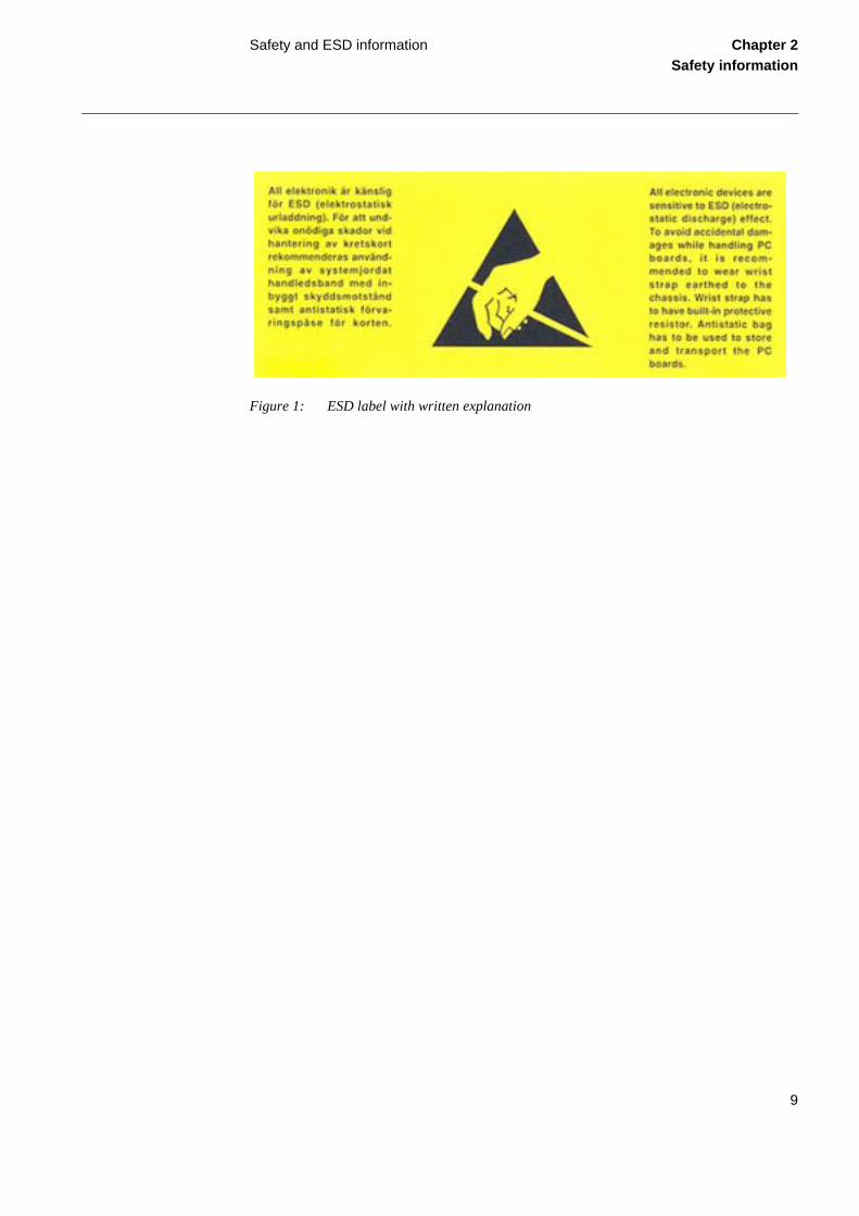
The end-user of the cubicle has to be aware that the cubicle contains ESD sensitive equipment. A warning label is therefor attached to the cubicle before delivery, see figure 1.
Connection point for protective earth
Indicates that a wrist ESD-bracelet shall be used when touching the terminal and when modules are to be exchanged or inserted
Informs that the equipment must be connected to protective earth before being energized
Warning label placed on all apparatuses/products, which are used on voltages exceeding 50V ac/75V dc and where the degree of protection against ingres-sion is lower than IP 20
Caution label. This part of the manual should be carefully read
9
Safety and ESD information Chapter 2Safety information
Figure 1: ESD label with written explanation

10
Safety and ESD information Chapter 2Safety information

11
About this chapter Chapter 3Mounting methods and details
Chapter 3 Mounting methods and details
About this chapterThis chapter describes different mounting methods and details.

12
Overview Chapter 3Mounting methods and details
1 OverviewMost of the IED 670s can be rack, flush or wall mounted with the use of different mounting kits, see figure2. An additional box of type RHGS can be mounted to one side of a 1/2 or 3/4 IED.
The different mounting kits contain all parts needed including screws and assembly instructions. The following mounting kits are available:
• Flush mounting kit• 19” Panel (rack) mounting kit• Wall mounting kit• Side-by-side mounting kit
The same mounting kit is used for side-by-side rack mounting and side-by-side flush mounting.
Note!The mounting kits must be ordered separately when ordering an IED. They are available as op-tions on the ordering sheet in “Accessories for IED 670”, see section 1.3 "Related documents" on page 2.
Generally, all the screws included in delivered mounting kits are of Torx type and a screwdriver of the same type is needed (Tx10, Tx15, Tx20 and Tx25).
Note!If other type of screws are to be used, be sure to use the dimensions of the screws that are given in this guide.
A B C D

13
Overview Chapter 3Mounting methods and details
Figure 2: Different mounting methods for IED 670
Description
A Flush mounting
B 19” Panel rack mounting
C Wall mounting
D Side-by-side rack or flush mounting

14
IED sizes and dimensions Chapter 3Mounting methods and details
2 IED sizes and dimensionsIED 670 are available in three different sizes, see figure 3. Small or medium HMI is available on all case sizes.
Figure 3: Available IED sizes
Description
A 6U 1/2 x 19” case
B 6U 3/4 x 19” case
C 6U 1/1 x 19” case

15
IED sizes and dimensions Chapter 3Mounting methods and details
2.1 Case without rear cover
Figure 4: Case without rear cover Figure 5: Case without rear cover with 19” rack mounting kit
xx04000448.vsd
CB
D
E
A
xx04000464.vsd
JG
F
K
H
Case size A B C D E F G H J K
6U, 1/2 x 19” 265.9 223.7 201.1 252.9 205.7 190.5 203.7 - 187.6 -
6U, 3/4 x 19” 265.9 336.0 201.1 252.9 318.0 190.5 316.0 - 187.6 -
6U, 1/1 x 19” 265.9 448.3 201.1 252.9 430.3 190.5 428.3 465.1 187.6 482.6
The H and K dimensions are defined by the 19” rack mounting kit
(mm)

16
IED sizes and dimensions Chapter 3Mounting methods and details
2.2 Case with rear cover
Figure 6: Case with rear cover.Figure 7: Case with rear cover and 19” rack
mounting kit.
Figure 8: Rear cover case with details.
xx05000501.vsd
B
D
E
A
Cxx05000502.vsd
JG
F
K
H
xx05000503.vsd
Case size A B C D E F G H J K
6U, 1/2 x 19” 265.9 223.7 242.1 255.8 205.7 190.5 203.7 - 228.6 -
6U, 3/4 x 19” 265.9 336.0 242.1 255.8 318.0 190.5 316.0 - 228.6 -
6U, 1/1 x 19” 265.9 448.3 242.1 255.8 430.3 190.5 428.3 465.1 228.6 482.6
The H and K dimensions are defined by the 19” rack mounting kit. All dimensions are in millimeters.
17
Flush mounting Chapter 3Mounting methods and details
3 Flush mounting
3.1 OverviewAll IED sizes, 1/2 x 19”, 3/4 x 19” and 1/1 x 19” and RHGS6 6U 1/4 x 19”, cases, can be flush mounted. Only a single case can be mounted in each cut-out on the cubicle panel, for class IP54 protection.
The flush mounting kit are utilized for IEDs of sizes: 1/2 x 19”, 3/4 x 19” and 1/1 x 19” and are also suitable for mounting of RHGS6, 6U 1/4 x 19” cases.
Note!Flush mounting cannot be used for side-by-side mounted IEDs when IP54 class must be fulfilled. Only IP20 class can be obtained when mounting two cases side-by-side in one (1) cut-out.
Note!To obtain IP54 class protection, an additional factory mounted sealing must be ordered when ordering the IED.
18
Flush mounting Chapter 3Mounting methods and details
3.2 Mounting procedure for flush mounting
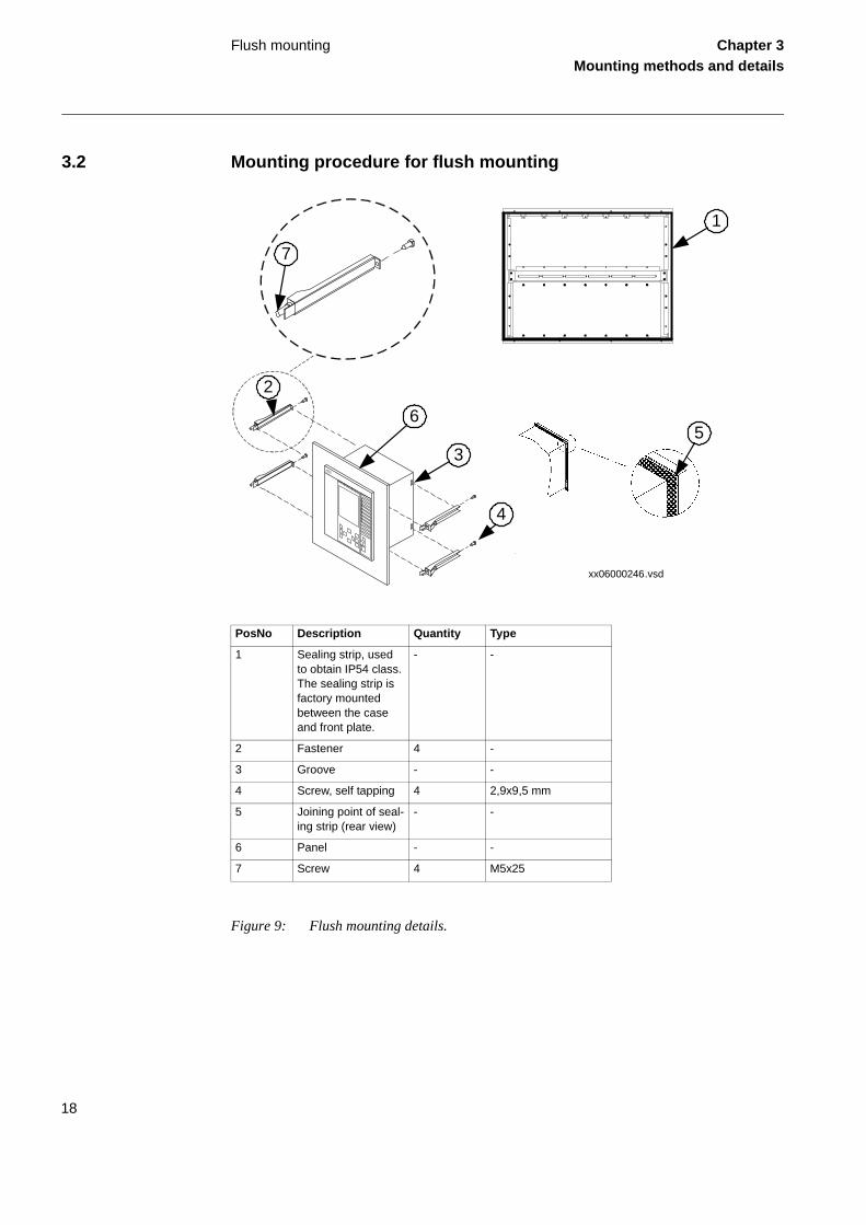
Figure 9: Flush mounting details.
PosNo Description Quantity Type
1 Sealing strip, used to obtain IP54 class. The sealing strip is factory mounted between the case and front plate.
- -
2 Fastener 4 -
3 Groove - -
4 Screw, self tapping 4 2,9x9,5 mm
5 Joining point of seal-ing strip (rear view)
- -
6 Panel - -
7 Screw 4 M5x25
1
35
xx06000246.vsd
4
2
6
7

19
Flush mounting Chapter 3Mounting methods and details
Procedure1. Cut an opening in the panel.
See section 3.4 "Flush mounting dimensions" on page 20 regarding di-mensions.
2. Carefully press the sealing strip around the IEDs collar. Cut the end of the sealing strip a few mm to long to make the joining point (5) tight.
The sealing strip is delivered with the mounting kit. The strip is long enough for the largest available IED.
3. Insert the IED into the opening (cut-out) in the panel.
4. Attach the fasteners to the IED.
Insert the panel end of the fastener in the gap between the IED and the panel. Insert the rear end of the fastener into the groove. Insert from the rear side and lightly tighten the screw (4)
Repeat this with the remaining fasteners.
5. Fix the IED by tightening all four (7) screws against the panel.
3.3 Ordering details
Table 1: Flush mounting kit
The flush mounting kit consists of 4 fastener (pos 2 in figure 9 "Flush mounting details." on page 18), seal-ing strip, screws (pos no 4 in figure 9 "Flush mounting details." on page 18) and assembly instruction.
Mounting kit Order code pre-configured IEDs
Ordering number
Flush mounting kit for all IED sizes E 1MRK 000 020-Y
Flush mounting kit + IP54 sealing (factory mounted). Cannot be ordered separately thus must be specified when ordering an IED.
F 1MRK 002 418-AA

20
Flush mounting Chapter 3Mounting methods and details
3.4 Flush mounting dimensions
Figure 10: Flush mounting
Case size
Tolerance
Cut-out dimensions (mm)
A
+/-1
B
+/-1
C D
6U, 1/2 x 19” 210.1 254.3 4.0-10.0 12.5
6U, 3/4 x 19” 322.4 254.3 4.0-10.0 12.5
6U, 1/1 x 19” 434.7 254.3 4.0-10.0 12.5
E = 188.6 mm without rear protection cover, 229.6 mm with rear protection cover
CA
B
ED
xx04000465.vsd

21
19” panel rack mounting Chapter 3Mounting methods and details
4 19” panel rack mounting
4.1 OverviewAll IED sizes can be mounted in a standard 19” cubicle rack by using the for each size suited mounting kit which consists of two mounting angles and fastening screws for the angles. The mounting angles are reversible which enables mounting of IED size 1/2 x 19” or 3/4 x 19” either to the left or right side of the cubicle.
Note!Please note that the separately ordered rack mounting kit for side-by-side mounted IEDs, or IEDs together with RHGS cases, is to be selected so that the total size equals 19”.
Note!When mounting the mounting angles, be sure to use screws that follows the recommended di-mensions. Using screws with other dimensions than the original may damage the PCBs inside the IED.

22
19” panel rack mounting Chapter 3Mounting methods and details
4.2 Mounting procedure for 19” panel rack mounting
Figure 11: 19” panel rack mounting details
Procedure1. Carefully fasten the mounting angles (1a, 1b) to the sides of the IED.
Use the screws (2) supplied in the mounting kit.
2. Place the IED assembly in the 19” panel.
3. Fasten the mounting angles with appropriate screws.
PosNo Description Quantity Type
1a, 1b Mounting angels, which can be mounted, either to the left or right side of the case.
2 -
2 Screw 8 M4x6
xx04000452.vsd
1a
2
1b

23
19” panel rack mounting Chapter 3Mounting methods and details
4.3 Ordering details
Table 2: Rack mounting kit
The 19" rack mounting kit consists of 2 mounting angles (pos 1a and 1b in figure 11 "19” panel rack mounting details" on page 22, mounting angle 1b has different size depending of total case size), fixing screws (pos 2 in fig figure 11 "19” panel rack mounting details" on page 22) and assembly instruction.
Mounting kit Order code pre-configured IEDs
Ordering number
19” rack mounting kit for one RHGS6
Consist of mounting angles 1a and a suitable size of 1b to reach 19”
- 1MRK 002 420-BE
19” rack mounting kit for 1/2 x 19” IED or 2 x RHGS6 or RHGS12
Consists of mounting angles 1a and a suitable size of 1b to reach 19”
A 1MRK 002 420-BB
19” rack mounting kit for 3/4 x 19” IED or 3 x RHGS6
Consists of mounting angles 1a and a suitable size of 1b to reach 19”
B 1MRK 002 420-BA
19” rack mounting kit for 1/1 x 19” IED
Consists of two mounting angles 1a
C 1MRK 002 420-CA
24
Wall mounting Chapter 3Mounting methods and details
5 Wall mounting
5.1 OverviewAll case sizes, 1/2 x 19”, 3/4 x 19” and 1/1 x 19”, can be wall mounted. It is also possible to mount the IED on a panel or in a cubicle.
Note!When mounting the side plates, be sure to use screws that follows the recommended dimensions. Using screws with other dimensions than the original may damage the PCBs inside the IED.

25
Wall mounting Chapter 3Mounting methods and details
5.2 Mounting procedure for wall mounting
Figure 12: Wall mounting details.
Procedure1. Mount the mounting bars onto the wall (4).
See section 5.5 "Wall mounting dimensions" on page 28 for mounting di-mensions.
Depending on the wall different preparations may be needed like drilling and inserting plastic or expander plugs (concrete/plasterboard walls) or threading (metal sheet wall).
PosNo Description Quantity Type
1 Bushing 4 -
2 Screw 8 M4x10
3 Screw 4 M6x12 or correspond-ing
4 Mounting bar 2 -
5 Screw 6 M5x8
6 Side plate 2 -
xx04000453.vsd
1
2
3
4
5
6

26
Wall mounting Chapter 3Mounting methods and details
2. Make all electrical connections to the IED terminal.
It is much easier to do this without the unit in place.
3. Mount the side plates to the IED.
4. Mount the IED to the mounting bars.
5.3 How to reach the rear side of the IEDThe IED can be equipped with a rear protection cover which is recommended to use with this type of mounting. See figure 13.
To reach the rear side of the IED, a free space of 80 mm is required on the unhinged side.
Figure 13: How to reach the connectors on the rear side of the IED.
Procedure1. Remove the inner screws (1), upper and lower on one side.
80 mm
View from above
1
en06000135.vsd
3
2
PosNo Description Type
1 Screw M4x10
2 Screw M5x8
3 Rear protection cover
-

27
Wall mounting Chapter 3Mounting methods and details
2. Remove all three fixing screws (2), on the opposite side, from wall support.
3. The IED can now be swung out for access to the connectors, after removing any rear protection.
5.4 Ordering details
Table 3: Wall mounting kit
Table 4: Protective cover for rear side
The wall mounting kit consist of 2 side plates (pos 6 in figure 12 "Wall mounting details." on page 25), 2 mounting bars (pos 4 in figure 12 "Wall mounting details." on page 25), fixing screws and bushings (pos 1, 2, 3 and 5 in figure 12 "Wall mounting details." on page 25) and assembly instruction.
Mounting kit Order code pre-configured IEDs
Ordering number
Wall mounting kit for all IED sizes D 1MRK 002 420-DA
Mounting kit Order code pre-configured IEDs Ordering number
Protective cover for rear side of RHGS6, 6U, 1/4 x 19”
-
1MRK 002 420-AE
Protective cover for rear side of IED, 6U, 1/2 x 19”
-
1MRK 002 420-AC
Protective cover for rear side of IED, 6U, 3/4 x 19”
-
1MRK 002 420-AB
Protective cover for rear side of IED, 6U, 1/1 x 19”
-
1MRK 002 420-AA

28
Wall mounting Chapter 3Mounting methods and details
5.5 Wall mounting dimensions
Figure 14: Wall mounting
Case size (mm) A B C D E
6U, 1/2 x 19” 292.0 267.1 272.8 390.0 243.0
6U, 3/4 x 19” 404.3 379.4 272.8 390.0 243.0
6U, 1/1 x 19” 516.0 491.1 272.8 390.0 243.0
en04000471.vsd
E
A
B
CD

29
Side-by-side 19” rack mounting Chapter 3Mounting methods and details
6 Side-by-side 19” rack mounting
6.1 OverviewIED case sizes, 1/2 x 19” or 3/4 x 19” and RHGS cases, can be mounted side-by-side up to a maximum size of 19”. For side-by-side rack mounting, the side-by-side mounting kit together with the 19” rack panel mounting kit must be used. The mounting kit has to be ordered separate-ly.
6.2 Mounting procedure for side-by-side rack mounting
Figure 15: Side-by-side rack mounting details.
Procedure 1. Place the two IEDs next to each other on a flat surface.
Note!When mounting the plates and the angles on the IED, be sure to use screws that follows the rec-ommended dimensions. Using screws with other dimensions than the original may damage the PCBs inside the IED.
PosNo Description Quantity Type
1 Mounting plate 2 -
2, 3 Screw 16 M4x6
4 Mounting angle 2 -
xx04000456.vsd
3
4
1
2

30
Side-by-side 19” rack mounting Chapter 3Mounting methods and details
2. Fasten a side-by-side mounting plate (1).
Use four of the delivered screws (2, 3).
3. Carefully turn the two IEDs up-side down.
4. Fasten the second side-by-side mounting plate.
Use the remaining four screws.
5. Carefully fasten the mounting angles (4) to the sides of the IED.
Use the screws available in the mounting kit.
6. Place the IED assembly in the rack.
7. Fasten the mounting angles with appropriate screws.
6.3 Ordering details
Table 5: Side-by-side mounting kit
6.4 IED 670 mounted with a RHGS6 caseAn 1/2 x 19” or 3/4 x 19” size IED can be mounted with a RHGS (6 or 12 depending on IED size) case. The RHGS case can be used for mounting a test switch of type RTXP 24. It also has enough space for a terminal base of RX 2 type for mounting of, for example, a DC-switch or two trip relays.
The side-by-side mounting kit consists of 2 mounting plates (pos 1 in figure 15 "Side-by-side rack mount-ing details." on page 29), fixing screws (pos 2 and 3 in figure 15 "Side-by-side rack mounting details." on page 29) and assembly instruction.
The side-by-side mounting kit does not include mounting angles or fixing screws for rack mounting. Appli-cable rack mounting kit, depending on total size of IEDs or test switches mounted side-by-side, must therefore be ordered separately according to table 2 "Rack mounting kit" on page 23.
When ordering an IED of 1/2 or 3/4 x 19" and a RTXP24 test switch module, the test switch is mounted in a RHGS 6 case which can be mounted side-by-side to the IED. A side-by-side mounting kit is included when ordering a test switch module.
Mounting kit Order code pre-configured IEDs
Ordering number
Side-by-side mounting kit -
1MRK 002 420-Z

31
Side-by-side 19” rack mounting Chapter 3Mounting methods and details
Figure 16: IED 670 (1/2 x 19”) mounted with a RHGS6 case containing a test switch module equipped with only a test switch and a RX2 terminal base.
xx06000180.vsd
8 88
7
5
6
3
4
2
7
5
6
7
5
6
3
4
2
3
4
2
1
1
1
2
1 1
1
8
7
5
6
3
4
2
2
2
1

32
Side-by-side flush mounting Chapter 3Mounting methods and details
7 Side-by-side flush mounting
7.1 OverviewIt is not recommended to flush mount side by side mounted cases if IP54 is required. If your ap-plication demands side-by-side flush mounting, the side-by-side mounting details kit and the 19” panel rack mounting kit must be used. The mounting kit has to be ordered separately. The max-imum size of the panel cut out is 19”.
Note! With side-by-side flush mounting installation, only IP class 20 is obtained. To reach IP class 54, it is recommended to mount the IEDs separately. For cut out dimensions of separately mounted IEDs, see section 3 "Flush mounting" on page 17.
Note!When mounting the plates and the angles on the IED, be sure to use screws that follows the rec-ommended dimensions. Using screws with other dimensions than the original may damage the PCBs inside the IED.

33
Side-by-side flush mounting Chapter 3Mounting methods and details
7.2 Mounting procedure for side-by-side flush mounting
Figure 17: Side-by-side flush mounting details (RHGS6 side-by-side with 1/2 x 19” IED).
Procedure1. Make a panel cut-out.
For panel cut out dimension, see section 7.4 "Side-by-side flush mount-ing dimensions" on page 34.
2. Carefully press the sealing strip around the IED collar. Cut the end of the sealing strip a few mm to long to make the joining point tight.
Repeat the same procedure with the second case.
The sealing strip is delivered with the mounting kit. The strip is long enough for the largest available IED.
3. Place the two IEDs next to each other on a flat surface.
PosNo Description Quantity Type
1 Mounting plate 2 -
2, 3 Screw 16 M4x6
4 Mounting angle 2 -
xx06000181.vsd
1 2
3
4

34
Side-by-side flush mounting Chapter 3Mounting methods and details
4. Fasten a side-by-side mounting plate (1).
Use four of the delivered screws (2, 3).
5. Carefully turn the two IEDs up-side down.
6. Fasten the second side-by-side mounting plate.
Use the remaining four screws.
7. Carefully fasten the mounting angles (4) to the sides of the IED.
Use the fixing screws available in the mounting kit.
8. Insert the IED into the cut-out.
9. Fasten the mounting angles with appropriate screws.
7.3 Ordering details
7.4 Side-by-side flush mounting dimensions
Figure 18: A 1/2 x 19” size IED 670 side-by-side with RHGS6.
To flush mount side-by-side mounted IEDs or test switches, where the total case size equals 1/2 x 19”, 3/4 x 19” or 1/1 x 19", the side-by-side mounting kit (for ordering details see table 5 "Side-by-side mounting kit" on page 30) shall be used. To flush mount side-by-side mounted cases the separately ordered rack mounting kit for 1/1 x 19" IED (for ordering details see table 2 "Rack mounting kit" on page 23) shall be used.
xx06000182.vsd

35
Side-by-side flush mounting Chapter 3Mounting methods and details
Figure 19: Panel-cut out dimensions for side-by-side flush mounting
Case size (mm)
Tolerance
A
±1
B
±1
C
±1
D
±1
E
±1
F
±1
G
±1
6U, 1/2 x 19” 214.0 259.3 240.4 190.5 34.4 13.2 6.4 diam
6U, 3/4 x 19” 326.4 259.3 352.8 190.5 34.4 13.2 6.4 diam
6U, 1/1 x 19” 438.7 259.3 465.1 190.5 34.4 13.2 6.4 diam
xx05000505.vsd
B
A
C
G
D
E
F

36
Side-by-side flush mounting Chapter 3Mounting methods and details

37
About this chapter Chapter 4Electrical connections
Chapter 4 Electrical connections
About this chapterThis chapter describes how to make the electrical connections.

38
Connecting to protective earth Chapter 4Electrical connections
1 Connecting to protective earthConnect the earthing screw (pos 1 in figure 20) on the rear of the IED unit to the closest possible earthing point in the cubicle. Electrical codes and standards require that protective earth cables are green/yellow conductors with a cross section area of at least 2.5 mm2 (AWG14). There are several protective earthing screws on an IED. The Power supply module (PSM), Transformer input modules (TRM) and the enclosure are all separately earthed, see figure 20 below.
The cubicle must be properly connected to the station earthing system. Use a conductor with a core cross section area of at least 4 mm2 (AWG 12).
Figure 20: Rear view of IED with one TRM showing earthing points.
PosNo Description
1 Main protective earth to chassis
2 Earthing screw to Power supply module (PSM)
3 Earthing screw to Transformer input module (TRM). (There is one earth connection per TRM)
1
en05000509.vsd
3
2
Note!Use the main protective earth screw (1) for connection to the stations earthing system. Earthing screws for PSM module (2) and TRM module (3) must be fully tightened to secure protective earth connection of these modules.
39
Connecting the power supply module Chapter 4Electrical connections
2 Connecting the power supply moduleThe wiring from the cubicle terminal block to the IED terminals (see figure 34 on page 64 for PSM connection diagram) must be made in accordance with the established guidelines for this type of equipment. The wires from binary inputs and outputs and the auxiliary supply must be routed separated from the current transformer cables between the terminal blocks of the cubicle and the IEDs connections. The connections are made on connector X11. For location of connec-tor X11, refer to section 3 "Rear side connectors" on page 58.

40
Connecting to CT and VT circuits Chapter 4Electrical connections
3 Connecting to CT and VT circuitsCTs and VTs are connected to the 24–pole connector of the Transformer input module (TRM) on the rear side of the IED. Connection diagram for TRM is shown in figure 29 on page 61.
Use a solid conductor with a cross section area between 2.5-6 mm2 (AWG14-10) or a stranded conductor with a cross section area between 2.5-4 mm2 (AWG14-12).
If the IED is equipped with a test-switch of type RTXP 24 COMBIFLEX wires with 20 A sock-ets must be used to connect the CT and VT circuits.
Connectors X401 and X402 (for location see section 3 "Rear side connectors" on page 58) for current and voltage transformer circuits are so called “feed-through terminal blocks” and are de-signed for conductors with cross sectional area up to 4 mm2 (AWG 12). The screws used to fasten the conductors should be tightened with a torque of 1Nm.

41
Connecting the binary input and output signals Chapter 4Electrical connections
4 Connecting the binary input and output signalsAuxiliary power and signals are connected using voltage connectors. Signal wires are connected to a female connector, see figure 21, which is then plugged into the corresponding male connec-tor, see figure 22, located at the rear of the IED. For location of BIM, BOM and IOM refer to section 3 "Rear side connectors" on page 58. Connection diagrams for BIM, BOM and IOM are shown in figure 30, figure 36 and figure 32 on page 63.
If the IED is equipped with a test-switch of type RTXP 24 COMBIFLEX wires with 20 A sock-ets, 1.5mm2 (AWG16) conductor area must be used to connect the auxiliary power.
Procedure1. Connect signals to the female connector
All wiring to the female connector should be done before it is plugged into the male part and screwed to the case. The conductors can be of rigid type (solid, stranded) or of flexible type.
The female connectors accept conductors with a cross section area of 0.2-2.5 mm2 (AWG 24-14). If two conductors are used in the same ter-minal, the maximum permissible cross section area is 0.2-1 mm2 (AWG 24-18 each).
If two conductors, each with area 1.5 mm2 (AWG 16) need to be connect-ed to the same terminal, a ferrule must be used. It is recommended to use Phoenix ferrules Al-Twin2 1,5-8 BK, Phoenix part No 32 00 82-3, see figure 23. This ferrule, is applied with the by Phoenix recommended crimping tool, Phoenix part No 12 06 36 6, see figure 24. No soldering is needed. Wires with a smaller gauge can be inserted directly into the fe-male connector receptacle and the fastening screw shall be tightened with a torque of 0.4 Nm (This torque applies to all binary connectors).
2. Plug the connector to the corresponding back-side mounted male connector
3. Lock the connector by fastening the lock screws
Figure 21: A female connector of type Phoenix 18 42 67 8
xx02000742.vsd

42
Connecting the binary input and output signals Chapter 4Electrical connections
Figure 22: Board with male connectors
Figure 23: Cable connectors
PosNo Description
1 Is ferrule, Phoenix Part No 32 00 82 3
2 A bridge connector, is used to jump terminal points in a connector. ABB Part No 1MKC 840 002-4.
12
1
xx06000168.vsd

43
Connecting the binary input and output signals Chapter 4Electrical connections
Figure 24: Phoenix crimping tool, Phoenix Part No 12 06 36 6

44
Making the screen connection Chapter 4Electrical connections
5 Making the screen connectionWhen using screened cables always make sure screens are earthed and connected according to applicable engineering methods. This may include checking for appropriate earthing points near the IED, for instance, in the cubicle and/or near the source of measuring. Ensure that earth con-nections are made with short (max. 10 cm) conductors of an adequate cross section, at least 6 mm2 (AWG10) for single screen connections.
Figure 25: Communication cable installation.
en06000190.vsd
Rx
Tx
Sc
Lc
Tx
Rx
Sc
LcCc
IED ExternalEquipment
1
3
22
PosNo Description
1 Outer shield
2 Protective earth screw
3 Inner shield
Note!Inner shielding of the cable shall be grounded at the external equipment end only. At the Relay terminal end, the inner shield must be isolated from protective ground.

45
About this chapter Chapter 5Optical connections
Chapter 5 Optical connections
About this chapterThis chapter describes how to make the optical connections.

46
Overview Chapter 5Optical connections
1 OverviewEach IED is provided with a communication interface, enabling it to connect to one or many sub-station level systems or equipment, either on the Substation Automation (SA) bus or Substation Monitoring (SM) bus.
Following communication protocols are available:
• IEC 61850-8-1 communication protocol• LON communication protocol• SPA or IEC 60870-5-103 communication protocol
Theoretically, several protocols can be combined in the same IED.

47
Connecting station communication interfaces (OEM and SLM)
Chapter 5Optical connections
2 Connecting station communication interfaces (OEM and SLM)The IED can, if ordered accordingly, be equipped with an optical ethernet module (OEM, see figure 33 on page 63), needed for IEC 61850 communication and a serial communication mod-ule (SLM, see figure 33 on page 63) for LON, SPA and IEC 60870–5–103 communication. In such cases optical ports are provided on the rear side of the case for connection of the optical fibers. For location of OEM and SLM, refer to section 3 "Rear side connectors" on page 58.
• Optical ports X311: A, B (Tx, Rx) and X311: C, D (Tx, Rx) on the OEM module are used for IEC 61850 communication. Connectors are of ST type. When the op-tical ethernet module is used, the protection plate for the galvanic connection must not be removed.
• Optical port X301: A, B (Tx, Rx) on the SLM module is used for SPA or IEC 60870-5-103 communication. Connectors are of ST type (glass) or HFBR Snap in (plastic).
• Optical port X301: C, D (Tx, Rx) on the SLM module is used for LON commu-nication. Connectors are of ST type (glass) or HFBR Snap in (plastic).
Connectors are generally color coded; connect blue or dark grey cable connectors to blue or dark grey (receive) back-side connectors. Connect black or grey cable connectors to black or grey (transmit) back-side connectors.
Caution!The fiber optical cables are very sensitive to handling. Do not bend too sharply. The minimum curvature radius is 15 cm for the plastic fiber cables and 25 cm for the glass fiber cables. If cable straps are used to fix the cables, apply with loose fit.
Always hold the connector, never the cable, when connecting or disconnecting optical fibers. Do not twist, pull or bend the fiber. Invisible damage may increase fiber attenuation thus making communication impossible.
Note!Please, strictly follow the instructions from the manufacturer for each type of optical ca-bles/connectors.

48
Connecting remote communication interfaces (LDCM)
Chapter 5Optical connections
3 Connecting remote communication interfaces (LDCM)The Line Data Communication Module (LDCM, see figure 33 on page 63) is the hardware used for the transfer of binary and analog signal data between IEDs in different protection schemes on the IEEE/ANSI C37.94 protocol. The optical ports on the rear side of the IED are X302, X303, X312 and X313. For location of LDCM module, refer to section 3 "Rear side connectors" on page 58.

49
About this chapter Chapter 6GPS antenna Installation
Chapter 6 GPS antenna Installation
About this chapterThis chapter describes how to install the GPS antenna.

50
Overview Chapter 6GPS antenna Installation
1 OverviewIn order to receive GPS signals from the satellites orbiting the earth a GPS antenna with appli-cable cable must be used.
Antenna cable is available in two different lengths, 20 and 40 meters.
Ordering number for the GPS accessories can be found in section 3 "Ordering details" on page 53.

51
Installing the GPS antenna Chapter 6GPS antenna Installation
2 Installing the GPS antenna
2.1 Antenna installationThe antenna is mounted on a console for mounting on a horizontal or vertical flat surface or on an antenna mast.
Figure 26: GPS antenna and mounting accessories
Mount the antenna and console clear of flat surfaces such as buildings walls, roofs and windows to avoid signal reflections. If necessary, protect the antenna from animals and birds which can affect signal strength. Also protect the antenna against lightning.
PosNO Description
1 GPS antenna
2 TNC connector
3 Console, 78x150 mm
4 Mounting holes 5.5 mm
5 Tab for securing of antenna cable
6 Vertical mounting position (on antenna mast etc.)
7 Horizontal mounting position
1
2
4
3
5
6
7
xx05000510.vsd

52
Installing the GPS antenna Chapter 6GPS antenna Installation
Always position the antenna and its console so that a continuous clear line-of-sight visibility to all directions is obtained, preferably more than 75%. A minimum of 50% clear line-of-sight vis-ibility is required for un-interrupted operation.
Figure 27: Antenna line-of-sight
2.2 Electrical installationUse a 50 ohm coaxial cable with a male TNC connector on the antenna end and a male SMA connector on the receiver end to connect the antenna to IED 670. Choose cable type and length so that the total attenuation is max. 26 dB at 1.6 GHz. A suitable antenna cable can be supplied with the antenna.
The antenna has a female TNC connector to the antenna cable. For location of GPS module, refer to section 3 "Rear side connectors" on page 58. Connection diagram for GPS module is shown in figure 35 on page 64.
A
99001046.vsd
Caution!Make sure that the antenna cable is not charged when connected to the antenna or to the receiv-er. Discharge the antenna cable by short-circuiting the end of the antenna cable with some metal device and then connect it to the antenna. When the antenna is connected to the cable, connect the cable to the receiver. IED 670 must be switched off when the antenna cable is connected.

53
Ordering details Chapter 6GPS antenna Installation
3 Ordering details
GPS antenna, including mounting kit 1MRK 001 640- AA
Cable for antenna, 20 m 1MRK 001 665- AA
Cable for antenna, 40 m 1MRK 001 665- BA

54
Ordering details Chapter 6GPS antenna Installation

55
About this chapter Chapter 7IED connectors
Chapter 7 IED connectors
About this chapterThis chapter describes the type and designation of connectors on the IED.

56
Overview Chapter 7IED connectors
1 OverviewThe quantity and designation of connectors depend upon the type and size of the IED. The rear cover plates are prepared with space for the maximum of HW options for each case size and the cut-outs that are not in use are covered with a plate from factory.
Table 6: Basic modules, always included
Table 7: Application specific modules
Module Description
Combined backplane module (CBM) A backplane PCB that carries all internal signals between modules in an IED. Only the TRM is not con-nected directly to this board.
Universal backplane module (UBM) A backplane PCB that forms part of the IED backplane with connectors for TRM, ADM etc.
Power supply module (PSM) Including a regulated DC/DC converter that supplies auxiliary voltage to all static circuits.
• An internal fail alarm output is available.
Numerical module (NUM) Module for overall application control. All information is processed or passed through this module, such as configuration, settings and communication.
Local Human machine interface (LHMI) The module consists of LED:s, an LCD, a push button keyboard and an ethernet connector used to connect a PC to the IED.
Transformer input module (TRM) Transformer module that galvanically separates the internal circuits from the VT and CT circuits. It has 12 analog inputs.
Analog digital conversion module (ADM) Slot mounted PCB with A/D conversion.
Module Description
Binary input module (BIM) Module with 16 optically isolated binary inputs
Binary output module (BOM) Module with 24 single outputs or 12 double-pole com-mand outputs including supervision function
Binary I/O module (IOM) Module with 8 optically isolated binary inputs, 10 out-puts and 2 fast signalling outputs.
Line data communication modules (LDCM) Modules used for digital communication to remote ter-minal.
Serial SPA/LON/IEC 60870-5-103 communication modules (SLM)
Used for SPA/LON/IEC 60870–5–103 communication
Optical ethernet module (OEM) PMC board for IEC 61850 based communication.
mA input module (MIM) Analog input module with 6 independent, galvanically separated channels.
GPS time synchronization module (GSM) Used to provide the IED with GPS time synchroniza-tion.

57
Front side connectors Chapter 7IED connectors
2 Front side connectors
Figure 28: IED front side connector
PosNo Description
1 IED serial communication port with RJ45 connector
2 Ethernet cable with RJ45 connectors
Note!The cable between PC and the IED serial communication port shall be a crossed-over Ethernet cable with RJ45 connectors. If the connection are made via a hub or switch, a standard Ethernet cable can be used.

58
Rear side connectors Chapter 7IED connectors
3 Rear side connectorsTable 8: Designations for 1/2 x 19” casing with 1 TRM slot
Table 9: Designations for 3/4 x 19” casing with 1 TRM slot
Module Rear Positions
PSM X11
BIM, BOM or IOM
X31 and X32 etc. to X51 and X52
GSM X51
SLM X301:A, B, C, D
LDCM X302:A, B
LDCM X303:A, B
OEM X311:A, B, C, D
LDCM X312:A, B
LDCM X313:A, B
TRM X401
Module Rear Positions
PSM X11
BIM, BOM, IOM or MIM X31 and X32 etc. to X101 and X102
GSM X101
SLM X301:A, B, C, D
LDCM X302:A, B
LDCM X303:A, B
OEM X311:A, B, C, D
LDCM X312:A, B
LDCM X313:A, B
TRM X401

59
Rear side connectors Chapter 7IED connectors
Table 10: Designations for 3/4 x 19” casing with 2TRM slot
Table 11: Designations for 1/1 x 19” casing with 1 TRM slot
Table 12: Designations for 1/1 x 19” casing with 2 TRM slots
Module Rear Positions
PSM X11
BIM, BOM, IOM or MIM X31 and X32 etc. to X71 and X72
GSM X71
SLM X301:A, B, C, D
LDCM X302:A, B
LDCM X303:A, B
OEM X311:A, B, C, D
LDCM X312:A, B
LDCM X313:A, B
TRM X401, 411
Module Rear Positions
PSM X11
BIM, BOM or IOM
X31 and X32 etc. to X161 and X162
MIM X31, X41, etc. or X161
GSM X161
SLM X301:A, B, C, D
LDCM X302:A, B
LDCM X303:A, B
OEM X311:A, B, C, D
LDCM X312:A, B
LDCM X313:A, B
TRM X401

60
Rear side connectors Chapter 7IED connectors
Module Rear Positions
PSM X11
BIM, BOM or IOM
X31 and X32 etc. to X131 and X132
MIM X31, X41, etc. or X131
GSM X131
SLM X301:A, B, C, D
LDCM X302:A, B
LDCM X303:A, B
OEM X311:A, B, C, D
LDCM X312:A, B
LDCM X313:A, B
TRM 1 X401
TRM 2 X411

61
Connection diagrams Chapter 7IED connectors
4 Connection diagrams
Figure 29: Transformer input module (TRM)
CT/VT-input designation according to figure 29
Current/volt-age configura-tion (50/60 Hz)
AI01
AI02
AI03
AI04
AI05
AI06
AI07 AI08 AI09 AI10 AI11 AI12
12I, 1A 1A 1A 1A 1A 1A 1A 1A 1A 1A 1A 1A 1A
12I, 5A 5A 5A 5A 5A 5A 5A 5A 5A 5A 5A 5A 5A
9I and 3U, 1A 1A 1A 1A 1A 1A 1A 1A 1A 1A 0-220V
0-220V
0-220V
9I and 3U, 5A 5A 5A 5A 5A 5A 5A 5A 5A 5A 0-220V
0-220V
0-220V
5I, 1A and 4I, 5A and 3U
1A 1A 1A 1A 1A 5A 5A 5A 5A 0-220V
0-220V
0-220V
6I and 6U, 1A 1A 1A 1A 1A 1A 1A 0-220V
0-220V
0-220V
0-220V
0-220V
0-220V
6I and 6U, 5A 5A 5A 5A 5A 5A 5A 0-220V
0-220V
0-220V
0-220V
0-220V
0-220V
6I, 1A 1A 1A 1A 1A 1A 1A - - - - - -
6I, 5A 5A 5A 5A 5A 5A 5A - - - - - -

62
Connection diagrams Chapter 7IED connectors
Figure 30: Binary input module (BIM). Input contacts named XA corresponds to rear position X31, X41, etc. and input contacts named XB to rear position X32, X42, etc.
Figure 31: mA input module (MIM)

63
Connection diagrams Chapter 7IED connectors
Figure 32: Binary in/out module (IOM). Input contacts named XA corresponds to rear position X31, X41, etc. and output contacts named XB to rear posi-tion X32, X42, etc.
Figure 33: Communication interfaces (OEM, LDCM, SLM and HMI)
Note to figure 33
1) Rear communication port IEC 61850, ST-con-nector
2) Rear communication port C37.94, ST-connec-tor
3) Rear communication port SPA/ IEC 60870-5-103, ST connector for glass alt. HFBR Snap-in connector for plastic as ordered
4) Rear communication port LON, ST connector for glass alt. HFBR Snap-in connector for plas-tic as ordered
5) Front communication port, Ethernet, RJ45 connector

64
Connection diagrams Chapter 7IED connectors
Figure 34: Power supply module (PSM)
Figure 35: GPS time synchronization module (GSM)
Figure 36: Binary output module (BOM). Output contacts named XA corresponds to rear position X31, X41, etc. and output contacts named XB to rear position X32, X42, etc.

65
About this chapter Chapter 8Test switch modules
Chapter 8 Test switch modules
About this chapterThis chapter describes the different test switch modules with configurations.

66
Overview Chapter 8Test switch modules
1 Overview
The test switch RTXP 24, see figure 38, is used to make it possible to test an IED in a fail-safe way. Inserting the test-plug handle, see figure 37, into the test switch automatically makes all preparations for a secure test in proper sequence. Blocking trip circuits, short circuit CT's and opening voltage circuits makes the IED available for secondary injection testing.
The Test switch module is to be ordered as an accessory when ordering the IED, see section “Or-dering” in “Accessories for IED 670”. Ordering number for the different test switches, DC-switch and mounting accessories can also be found in section 2 "Ordering details" on page 69.
As a option, a COMBIFLEX DC-switch can be ordered and mounted in one of the two seats RX 2 terminal base, see figure 39. The RX 2 terminal base can also be used for e.g. additional trip-ping relays and reduce the cost for an additional case or rack.
Each test switch RTXP 24 is equipped with a signal contact no 29–30, located at the top on right hand housing (see section 3 "Test switch configurations" on page 71.. This contact is used for signaling of test in progress, which is very important especially during test of differential pro-tections.
Figure 37: Test-plug handle RTXH 24 Figure 38: Test switch RTXP 24
xx02000699.vsd
Note!20A COMBIFLEX terminal sockets (2658 636-1) and multi stranded and tinplated wire of 2.5 mm2 must be available for connection of the IED to the test switch module.
Note!For connection of contacts 29 and 30, a multi stranded and tinplated wire of 1.5mm2 and 10A terminal sockets (2658 634-1) are needed.

67
Overview Chapter 8Test switch modules
PosNo Description
1 3 apparatus bars 12C, Ordering no: 2175 323-1
2 9 ADA 637-12 screws
8
7
5
6
3
4
2
1
1
8
7
5
6
3
4
2
2 210
1
1
7
6
5
4
3
xx02000700.vsd
4
2

68
Overview Chapter 8Test switch modules
Figure 39: A typical test switch module with a RTXP 24 and a optional DC-switch mounted in one RX 2 terminal base
For each type of IED, one or more alternatives of recommended test switch is given, depending on application and if an internal or external neutral is needed.
3 RTXP 24 test switch
4 Mounting plate kit for RTXP 24
5 Terminal base RX 2
6 DC-switch
7 RHGS 6 case
PosNo Description
Note!One test switch is required for each transformer input module (TRM).

69
Ordering details Chapter 8Test switch modules
2 Ordering details
Selection of a RTXP 24 test switch for each ordered test switch module is required. See appli-cable IED Buyer's guide for recommendations. Please refer to section “Related documents”.
Table 13: Test switch
The test switch module consists of a RHGS 6 case including a RTXP 24 test switch and if no other options are selected an empty two seat COMBIFLEX terminal base RX2 is mounted at the lower part of the mod-ule (see figure 39 "A typical test switch module with a RTXP 24 and a optional DC-switch mounted in one RX 2 terminal base" on page 68).
A side-by-side mounting kit (see table 5 "Side-by-side mounting kit" on page 30) is always included in the delivery of a test switch module. To flush mount side-by-side mounted test switches, the separately ordered 1/1 x 19” rack mounting kit shall be used. To rack mount side-by-side mounted test switches applicable rack mounting kit, to reach 19”, shall be used (see table 2 "Rack mounting kit" on page 23). Observe that cut-outs in panel must be made according to dimensions given for side-by-side flush mount-ing (see table 7.4 "Side-by-side flush mounting dimensions" on page 34
When ordering an IED 670 (all sizes) and a test switch module, the test switch module will be delivered separately, neither mounted side-by-side or wired to the IED.
Test switch module Order code pre-configured IEDs Ordering number
Test switch module RTXP24 - 1MRK 000 371-FA
Test switch configuration - RK 926 315-BD
- RK 926 315-BX
- RK 926 315-BH
- RK 926 315-AK
- RK 926 315-AC
- RK 926 315-BE
- RK 926 315-BV
- RK 926 315-BL
- RK 926 315-CA
- RK 926 315-AV
On/off switch for the DC-supply - RK 795 017-AA
Labels with symbols for RTXP - 1MRK 000 132-53
Mounting kit for RTXP 24 in 4U rack assembly - 1MRK 000 020-BT

70
Ordering details Chapter 8Test switch modules
Note!Leads with 20 A Combiflex socket on one end and insulation stripped on the other end must be used to connect the test switch to the terminal. To connect the signal contact of the test switch and the DC switch, leads with 10 A Combiflex socket on one end must be used.

71
Test switch configurations Chapter 8Test switch modules
3 Test switch configurationsTable 14: Recommended RTXP 24 contact configuration
REC 670 RED 670 REL 670 RET 670 REB 670
RK 926 315-AK
Single breaker/Single or three phase trip, inter-nal neutral
X X X
RK 926 315-AC
Single breaker/Single or three phase trip, exter-nal neutral
X X X
RK 926 315-BD
Two winding transformer with internal neutral X
RK 926 315-BE
Multi breaker/Single or three phase trip, internal neutral
X X X
RK 926 315-BH
Two winding transformer with external neutral X
RK 926 315-BV
Multi breaker/Single or three phase trip, external neutral
X X X
RK 926 315-BX
Three winding transformer with internal neutral X
RK 926 315-AV
External earthing, 16 binary signals X
RK 926 315-CA
Internal earthing, 6 binary signals X

72
Test switch configurations Chapter 8Test switch modules
Figure 40: RK 926 315-AK Figure 41: RK 926 315-AC Figure 42: RK 926 315-BD
Figure 43: RK 926 315-BE Figure 44: RK 926 315-BH Figure 45: RK 926 315-BV
xx06000171 xx06000172 xx06000174
xx06000173 xx06000175 xx06000170

73
Test switch configurations Chapter 8Test switch modules
The contacts 29–30 on the RTXP 24 test switch shall be connected to the input of test function block to allow activation of functions individually during test.
Figure 46: RK 926 315-BX Figure 47: RK 926 315-AV Figure 48: RK 926 315-CA
xx06000169 xx06000224 xx06000225

74
4U 19” rack mounting of test switches Chapter 8Test switch modules
4 4U 19” rack mounting of test switchesIf the cubicle assembly consists of more than one IED 670 and needs more than one test switch totally, it can be advantageous to mount up to four test switches in a 4U 19” rack by using the side-by-side mounting kit instead of mounting each test switch in a separate RHGS 6 case. A distance of min. 1C (7mm) is required between each test switch in order to allow for the opening of the cover locks, see figure 49 and figure 50.
Table 15: An example of IED 670 cubicle application
Figure 49: Example of cubicle configuration
Figure 50: 6 RTXP 24 test switches, two RX4 and one RX2H.
PosNo Description
1 X pcs RTXP 24
xx06000176.vsd
IED 670
IED 670
IED 6701
2
31
xx06000177.vsd
6
1
5
4

75
4U 19” rack mounting of test switches Chapter 8Test switch modules
2 X pcs RXMS 1
X pcs DC-switch
3 X pcs of 4U 19” racks, with door
4 RX2H terminal base
5 RX4 terminal base
6 Mounting kit for RTXP 24
PosNo Description

76
4U 19” rack mounting of test switches Chapter 8Test switch modules

77
About this chapter Chapter 9Mounting in cubicles
Chapter 9 Mounting in cubicles
About this chapterThis chapter describes the mounting of units in cubicles.

78
Overview Chapter 9Mounting in cubicles
1 OverviewThe cubicle’s design shall take into account all the electrical and environmental demands arising from the location of the cubicle.
The cubicle should be designed according to the international standard publication IEC 439-1 and to other IEC publications referring to this standard.
Degrees of protection as per IEC 60 529: IP21, IP41, IP43 or IP54.
The earthquake protection of the cubicle should follow the standard, IEEE 693 draft 5.

79
Requirements Chapter 9Mounting in cubicles
2 Requirements
2.1 Degrees of protectionThe IEC 60 529 describes standard degrees of protection provided by enclosures (IP code) that a product is designed to provide when properly installed.
2.1.1 Identification examples using the IP codeThe explanation of the Alpha-numeric IP code system can be illustrated as shown in figure 51.
Figure 51: Explanation of the Alpha-numeric IP code system
Using the IP code according IEC 60 529, the degrees of protection of the equipment are IP21, IP41, IP43 or IP54. The IP code components are described in table 16.
Table 16: IP code and its meaning for the protection of the equipment
where:
2 Protected against ingress of solid objects greater than 12 mm in diameter
1 Protected against ingress of dripping water
Component Figures Description
2 Protected against ingress of solid objects greater than 12 mm in diameter
First identification number 4 Protected against ingress of solid objects greater than 1 mm in diameter
5 Protected against dust
1 Protected against ingress of dripping water
Second identification number 3 Protected against ingress of spraying water
4 Protected against ingress of splashing water
en04000317.vsd
IP 2 1
Identification letter
First identification number
Second identification number

80
Requirements Chapter 9Mounting in cubicles
2.2 Environmental aspectsThe cubicle can be equipped with thermostat (figure 52) controlled heating elements (figure 53) to prevent condensation. Normal cubicles are designed and fitted for indoor use in a dry envi-ronment or at a reasonable humidity and air pollution level.
2.3 Earthquake protectionThe standard IEEE 693 draft 5 states recommended practice for seismic design of substations. The cubicle should be able to sustain a maximum ground acceleration (ZPA) equivalent to 0.5g in areas with a high risk for seismic shocks.
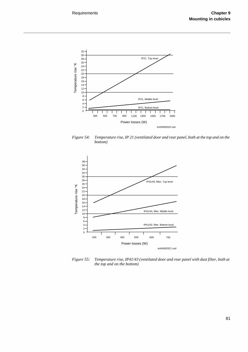
2.4 Power lossesThe temperature rises in a cabinet due to the power losses from the equipment housed in it. It also depends on the cabinet’s degree of protection (airtightness). Self-ventilated cooling is also highly dependent on the type of equipment involved and its location in the cabinet.
Equipment placed to ensure free air circulation around a heat source can be expected to emit more heat for the same increase in temperature than equipment which is not so well situated. Ex-pected power losses at certain permissible temperature rises can also only be given as guidelines as shown in figure 54, figure 55 and figure 56.
Figure 52: Cubicle thermostat Figure 53: Cubicle heating element
81
Requirements Chapter 9Mounting in cubicles
Figure 54: Temperature rise, IP 21 (ventilated door and rear panel, both at the top and on the bottom)
Figure 55: Temperature rise, IP41/43 (ventilated door and rear panel with dust filter, both at the top and on the bottom)
2468
101214161820222426283032
en04000320.vsd
300 500 700 900 1100 1300 1500 1700 1900
0
Power losses (W)
Tem
pera
ture
rise
°K
IP21, Top level
IP21, Middle level
IP21, Bottom level
2468
101214161820222426283032
en04000321.vsd
0
Power losses (W)
Tem
pera
ture
rise
°K
IP41/43, filter, Top level
IP41/43, filter, Middle level
IP41/43, filter, Bottom level
343638
200 300 400 500 600 700

82
Requirements Chapter 9Mounting in cubicles
Figure 56: Temperature rise, IP54 (sealed cubicle)
2.5 Ambient temperature
2.5.1 Maximum permissible ambient temperatureThe relays are designed for a maximum ambient temperature of 55°C at 110% of rated voltage.
The permissible ambient temperature stated for a relay refers to the average temperature sur-rounding the relay itself and not the temperature in the control room, where the relay’s cubicle or panel is located.
If a relay is mounted in a cubicle, case or other sealed enclosure, consideration must be given to the increase in temperature, resulting from the power losses in the equipment.
2.5.2 Permissible temperature increaseThe maximum permissible ambient temperature for relays mounted in a case or cubicle is, in reality, less than the specified 55°C due to temperature rises in the case and cubicle.
The temperature rise must be considered when designing control rooms. The temperature rise for the room ambient temperature compared to the relay ambient temperature could be as high as 15°C if the maximum permissible power losses given in table 17 are applicable.
The actual power losses will generally be less than the maximum permissible values and the temperature rise will be less than 15°C. With the maximum permissible room ambient temper-ature corresponding to +55°C, the permissible relay ambient temperature could be +40°C.
5
10
15
20
25
30
en04000322.vsd
0
Power losses (W)
Tem
pera
ture
rise
°K
IP54, Top level
IP54, Middle level
IP54, Bottom level
35
200 300 400 500 600
40
45

83
Requirements Chapter 9Mounting in cubicles
If the room temperature is higher, it is necessary to keep the increase less than 15°C. This can be achieved either by mounting the equipment in several cubicles or cases in order to reduce the supplied power losses per cubicle or case, or by improving cooling through increased natural ventilation or by forced ventilation using a fan.
The total power losses of the relays incorporated in a case or cubicle are usually too low to cause a 15°C temperature increase. However, there are two situations when it may be necessary to ob-serve the total power losses and to rearrange the relaying equipment. It may then also be neces-sary to reduce the total losses per frame or cubicle.
The first situation is when the auxiliary voltage supply is 220 or 250 V dc for several voltage or current measuring relays (2-3 pcs) with a fairly high power consumption, positioned in the same equipment frame or in equipment frames mounted close to each other. It is not possible to fill all positions in a cubicle or a rack or otherwise to pack the above relays too closely and still stay within the 15°C rise in the air surrounding the relay.
The second situation concerns auxiliary relays. There is a limitation to the numbers of continu-ously energized auxiliary relays that may be included in a RHGS or RHGX case or equipment frame and still stay within the 15°C rise limit. For example in an application of continuously en-ergized interposing relays. It is the temperature rise rather than the physical space which may limit the number of relays in a case or frame.
2.5.3 Permissible power lossesConcerning permissible relay power losses in cases of type RHGS or RHGX, consideration must be given to how the case is mounted when defining the permissible power losses.
Example: When a case is flush-mounted at the front of a cubicle1. Take the calculated temperature increase within the case2. Add the temperature increase of the air in the cubicle3. Calculate the total temperature increase in the case in relation to room tempera-
ture
Relaying equipment in cubicleTable 17 states the recommended values of permissible power losses of relaying equipment mounted in the D-plane (hinged frame or front plane) and the B-plane (rear mounting plane).
2.5.4 Temperature riseA calculation of the temperature rise within an RHGS or RHGX case mounted in a cubicle is shown in equation 1.
Note!It is recommended to mount only transformers, resistors and similar apparatuses in the B-plan. It is not recommended to mount relays in the B-plane, as the air circulation is minimal.

84
Requirements Chapter 9Mounting in cubicles
(Equation 1)
Table 17: Permissible power losses for 15°C temperature increase in RHGS and RGHX cases
Where:
Θrelay is the increase of the ambient temperature of the relay
KH is the RHGS or RGHX case thermal resistance
PH is the total power loss of the relay in the case
KS is the thermal resistance of the cubicle (for the cubicles according to table 17)
PS is the total power loss in the cubicle
Case type °C/W (KH) W
RHGS 6 2.50 6
RHGS 12 1.50 10
RHGS 20 0.90 17
RHGX 4 2.50 6
RHGX 8 1.80 8
RHGX 12 1.40 11
RHGX 20 0.90 17
RHGX 40 0.65 23
relay ΗΘ H S S= K + P + K + P

85
Requirements Chapter 9Mounting in cubicles
Table 18: Permissible power losses in a cubicle type (ABB VHS200, 700mm) for maxi-mum 15°C temperature increase in the relay ambient
1) Refers to several similar equipment frames with regard to power losses and with the power distributed over the whole equipment frame.
2) Also applicable to equipment frames mounted close to each other if every alternate equipment frame has a low continuous power loss (approximately 5 W). It is desirable to mount the equip-ment frames in the cubicles with maximum possible space between them, to ensure the best pos-sible heat dissipation.
3) The heater should be disconnected by a thermostat set for maximum 45°C.
4) Also applicable to locations where the cubicle is located back-to-back or close to a wall (with a distance of approximately 50 mm between the back of the cubicle and the wall).
5) Self-ventilated design according to figure 57.
Permissible power losses Thermal resis-tance of the cubicle
Cubicle location Code Cubicle design
Equipment frames above and underneath1)
Equipment frames with 4U space between each frame2)
Totally in cubicle
KS
W/4U-equipment frame W/cubicle Example of cubi-cle location
°C/W
Freestanding Cubi-cle
A1 Sealed cubi-cle 17 28 170 170 W 0.09
A2 Tropical design3)
A3 Ventilated design5)
25 40 250 170 W 0.06
Mounted on the side of one cubicle with approximately. the same power losses4)
B1 Sealed cubi-cle 13 21 130 130 W 0.12
B2 Tropical design3)
130 W
B3 Ventilated design5)
22 35 220 220 W
220W
0.07
Several cubicles located in a row with maximum permissi-ble power losses
C1 Sealed cubi-cle 11 17 110
130 W
110 W 0.14
C2 Tropical design3)
110 W
130 W
C3 Ventilated design3)
20 30 200 220 W
200 W
220 W
0.08

86
Requirements Chapter 9Mounting in cubicles
2.5.5 Self-ventilated design of the cubicle
Figure 57: Self ventilated design of the cubicle
Table 17 is applicable for convection in sealed or self-ventilated cubicles with a design accord-ing to figure 57. When the power losses are approximately evenly distributed in the equipment frames, the temperature increase should not exceed 15°C.
Sources of maximum heat loss, such as power supplies for static relays and continuously ener-gized auxiliary relays, should preferably not be located too close to each other. They should be located with the maximum possible spacing, to ensure the lowest possible temperature in the sur-rounding air.
The equipment frames containing relays with the highest power losses should preferably be po-sitioned as far down as possible in the cubicle.
The temperature increase should be calculated when designing the layout of relaying equipment. This is done by adding the power losses at rated voltage for all the relays in the cubicle that are simultaneously energized including auxiliary relays, and comparing the calculated values with those in table 17. Normally, it is sufficient to calculate with only the power losses of the auxil-iary voltage supply for the static and numerical relays and thus to ignore the losses of signal cir-cuits.
PosNo Description
1 Raised roof. The roof plate is raised 20 mm to provide an outlet for heated air.
2 Trim plate with vents that provides an outlet for heated air.
3 Protective door with vents, when required.
4 Door vents.
5 Kick plate with vents that provides cool air for the rear mounting plane.
xx04000324.vsd
5
4
3
2
1

87
Requirements Chapter 9Mounting in cubicles
The power losses in table 17 shall be calculated based on the losses at 110% of rated voltage, as obtained from the technical data tables (refer to the Buyer's Guide for the respective relay type). The temperature rise of 15°C has, however, been based on the relays operating at their maximum permissive voltage. For relays operating at their rated voltage the permitted losses in table 17 will result in a temperature rise less than that specified.

88
Earth connection Chapter 9Mounting in cubicles
3 Earth connectionAll units in the cubicle shall be earthed through the cubicle framework. All units must be well fixed and the screws tightened correctly.
Equipment with a connector (possibly a screw) for protected earth shall be connected to the earthing bar in the cubicle with a green/yellow cable. The minimum cross section area of the conductor shall be selected according to the maximum power supply or a minimum cross section area of 1.5 mm2.
Figure 58: Equipment label, marking the connection point for protective earth
For a cubicle with a hinged frame, the frame shall be earthed to the cubicle frame with two green/yellow wires, each with a minimum cross section area of 6 mm2. One of the wires shall be mounted at the top and the other to the bottom of the cubicle.
Figure 59: Earth cable
A vertical earthing bar (see figure 60), size 12 x 3 mm, or a horizontal earthing bar (see figure 61), size 30 x 10 mm, shall be installed in the base of the cubicle.

89
Earth connection Chapter 9Mounting in cubicles
When two or more cubicles are mounted side-by side, the earthing bars shall be joined together with joining pieces, see figure 62. The earthing bar is then connected to an earth grid, or equiv-alent, in the plant.
Figure 62: Cubicles mounted side-by-side with horizontal earthing bars
Figure 60: Vertical earthing bar Figure 61: Horizontal earthing bar

90
Earth connection Chapter 9Mounting in cubicles

91
About this chapter Chapter 10Glossary
Chapter 10 Glossary
About this chapterThis chapter contains a glossary with terms, acronyms and abbreviations used in ABB technical documentation.

92
Glossary Chapter 10Glossary
1 Glossary
AC Alternating current
A/D converter Analog to digital converter
ADBS Amplitude dead -band supervision
AIM Analog input module
ANSI American National Standards Institute
AR Autoreclosing
ArgNegRes Setting parameter/ZD/
ArgDir Setting parameter/ZD/
ASCT Auxiliary summation current transformer
ASD Adaptive signal detection
AWG American Wire Gauge standard
BBP Busbar protection
BFP Breaker failure protection
BIM Binary input module
BOM Binary output module
BR External bi-stable relay
BS British standard
BSR Binary signal transfer function, receiver blocks
BST Binary signal transfer function, transmit blocks
C37.94 IEEE/ANSI protocol used when sending binary signals between IEDs
CAN Controller Area Network. ISO standard (ISO 11898) for serial communi-cation
CAP 531 Configuration and programming tool
CB Circuit breaker
CBM Combined backplane module
CCITT Consultative Committee for International Telegraph and Telephony. A United Nations sponsored standards body within the International Tele-communications Union.
CCM CAN carrier module
CEM Controller area network emulation module
CIM Communication interface module
CMPPS Combined mega pulses per second
CO cycle Close-open cycle

93
Glossary Chapter 10Glossary
Co-directional Way of transmitting G.703 over a balanced line. Involves two twisted pairs making it possible to transmit information in both directions
COMTRADE Standard format according to IEC 60255-24
Contra-directional Way of transmitting G.703 over a balanced line. Involves four twisted pairs of with two are used for transmitting data in both directions, and two pairs for transmitting clock signals
CPU Central processor unit
CR Carrier receive
CRC Cyclic redundancy check
CS Carrier send
CT Current transformer
CVT Capacitive voltage transformer
DAR Delayed auto-reclosing
DARPA Defense Advanced Research Projects Agency (The US developer of the TCP/IP protocol etc.)
DBDL Dead bus dead line
DBLL Dead bus live line
DC Direct current
DFT Discrete Fourier transform
DIP-switch Small switch mounted on a printed circuit board
DLLB Dead line live bus
DR Disturbance recorder
DRH Disturbance report handler
DSP Digital signal processor
DTT Direct transfer trip scheme
EHV network Extra high voltage network
EIA Electronic Industries Association
EMC Electro magnetic compatibility
EMF Electro motive force
EMI Electro magnetic interference
EnFP End fault protection
ESD Electrostatic discharge
FOX 20 Modular 20 channel telecommunication system for speech, data and protection signals
FOX 512/515 Access multiplexer
FOX 6Plus Compact, time-division multiplexer for the transmission of up to seven duplex channels of digital data over optical fibers
FXM IEC 61850, Optical ethernet card

94
Glossary Chapter 10Glossary
G.703 Electrical and functional description for digital lines used by local tele-phone companies. Can be transported over balanced and unbalanced lines
G.711 Standard for pulse code modulation of analog signals on digital lines
GCM Communication interface module with carrier of GPS receiver module
GI General interrogation command
GIS Gas insulated switchgear
GOOSE Generic object oriented substation event
GPS Global positioning system
GSM GPS time synchronization module
HDLC protocol High level data link control, protocol based on the HDLC standard
HFBR connector type Plastic fiber connector
HMI Human machine interface
HSAR High speed auto reclosing
HV High voltage
HVDC High voltage direct current
IDBS Integrating dead band supervision
IEC International Electrical Committee
IEC 60044-6 IEC Standard, Instrument transformers – Part 6: Requirements for pro-tective current transformers for transient performance
IEC 60870-5-103 Communication standard for protective equipment. A serial master/slave protocol for point-to-point communication
IEC 61850 Substation Automation communication standard
IEEE Institute of Electrical and Electronics Engineers
IEEE 802.12 A network technology standard that provides 100 Mbits/s on twisted-pair or optical fiber cable
IEEE P1386.1 PCI Mezzanine card (PMC) standard for local bus modules. References the CMC (IEEE P1386, also known as Common mezzanine card) stan-dard for the mechanics and the PCI specifications from the PCI SIG (Special Interest Group) for the electrical EMF Electro Motive Force.
IED Intelligent electronic device
I-GIS Intelligent gas insulated switchgear
IOM Binary input/output module
Instance When several occurrences of the same function are available in the IED they are referred to as instances of that function. One instance of a func-tion is identical to another of the same kind but will have a different num-ber in the IED user interfaces. The word instance is sometimes defined as an item of information that is representative of a type. In the same way an instance of a function in the IED is representative of a type of function.

95
Glossary Chapter 10Glossary
IP 1. Internet protocol. The network layer for the TCP/IP protocol suite widely used on Ethernet networks. IP is a connectionless, best-effort packet switching protocol. It provides packet routing, fragmentation and re-assembly through the data link layer.
2. Ingression protection according to IEC standard
IP 20 Ingression protection, according to IEC standard, level 20
IP 40 Ingression protection, according to IEC standard, level 40
IP 54 Ingression protection, according to IEC standard, level 54
ITU International Telecommunications Union
LAN Local area network
LIB 520 High voltage software module
LCD Liquid crystal display
LDCM Line differential communication module
LDD Local detection device
LED Light emitting diode
LNT LON network tool
LON Local operating network
MCB Miniature circuit breaker
MCM Mezzanine carrier module
MIM Milli-ampere module
MPM Main processing module
MVB Multifunction vehicle bus. Standardized serial bus originally developed for use in trains.
NCC National Control Centre
NUM Numerical module
OCO cycle Open-close-open cycle
OCP Overcurrent protection
OLTC On load tap changer
OV Over voltage
Overreach A term used to describe how the relay behaves during a fault condition. For example a distance relay is over-reaching when the impedance pre-sented to it is smaller than the apparent impedance to the fault applied to the balance point, i.e. the set reach. The relay “sees” the fault but per-haps it should not have seen it.
PCI Peripheral component interconnect, a local data bus
PCM Pulse code modulation
PCM 600 Protection and control IED manager
PISA Process interface for sensors & actuators
POTT Permissive overreach transfer trip

96
Glossary Chapter 10Glossary
Process bus Bus or LAN used at the process level, that is, in near proximity to the measured and/or controlled components
PSM Power supply module
PST Parameter setting tool
PT ratio Potential transformer or voltage transformer ratio
PUTT Permissive underreach transfer trip
RASC Synchrocheck relay, COMBIFLEX
RCA Relay characteristic angle
REVAL Evaluation software
RFPP Resistance for phase-to-phase faults
RFPE Resistance for phase-to-earth faults
RISC Reduced instruction set computer
RMS value Root mean square value
RS422 A balanced serial interface for the transmission of digital data in point-to-point connections
RS485 Serial link according to EIA standard RS485
RS530 A generic connector specification that can be used to support RS422, V.35 and X.21 and others.
RTC Real time clock
RTU Remote terminal unit
SA Substation Automation
SC Switch or push-button to close
SCS Station control system
SCT System configuration tool according to standard IEC 61850
SLM Serial communication module. Used for SPA/LON/IEC communication.
SMA connector Subminiature version A, A threaded connector with constant impedance.
SMS Station monitoring system
SNTP Simple network time protocol – is used to synchronize computer clocks on local area networks. This reduces the requirement to have accurate hardware clocks in every embedded system in a network. Each embed-ded node can instead synchronize with a remote clock, providing the required accuracy.
SPA Strömberg protection acquisition, a serial master/slave protocol for point-to-point communication
SRY Switch for CB ready condition
ST Switch or push-button to trip
Starpoint Neutral point of transformer of generator
SVC Static VAr compensation
TC Trip coil

97
Glossary Chapter 10Glossary
TCS Trip circuit supervision
TCP Transmission control protocol. The most common transport layer proto-col used on Ethernet and the Internet.
TCP/IP Transmission control protocol over Internet Protocol. The de facto stan-dard Ethernet protocols incorporated into 4.2BSD Unix. TCP/IP was developed by DARPA for internet working and encompasses both net-work layer and transport layer protocols. While TCP and IP specify two protocols at specific protocol layers, TCP/IP is often used to refer to the entire US Department of Defense protocol suite based upon these, including Telnet, FTP, UDP and RDP.
TEF Time delayed earth-fault protection function
TNC connector Threaded Neill Concelman, A threaded constant impedance version of a BNC connector
TPZ, TPY, TPX, TPS Current transformer class according to IEC
Underreach A term used to describe how the relay behaves during a fault condition. For example a distance relay is under-reaching when the impedance presented to it is greater than the apparent impedance to the fault applied to the balance point, i.e. the set reach. The relay does not “see” the fault but perhaps it should have seen it. See also Overreach.
U/I-PISA Process interface components that deliver measured voltage and cur-rent values
UTC Coordinated universal time. A coordinated time scale, maintained by the Bureau International des Poids et Mesures (BIPM), which forms the basis of a coordinated dissemination of standard frequencies and time signals. UTC is derived from International Atomic Time (TAI) by the addi-tion of a whole number of "leap seconds" to synchronize it with Universal Time 1 (UT1), thus allowing for the eccentricity of the Earth's orbit, the rotational axis tilt (23.5 degrees), but still showing the Earth's irregular rotation, on which UT1 is based. The Coordinated Universal Time is expressed using a 24-hour clock and uses the Gregorian calendar. It is used for aeroplane and ship navigation, where it also sometimes known by the military name, "Zulu time". "Zulu" in the phonetic alphabet stands for "Z" which stands for longitude zero.
UV Undervoltage
V.36 CCITT interface for 4 wire data communication with a speed exceeding 48Kkbps.
WEI Weak end infeed logic
VT Voltage transformer
X.21 A digital signalling interface primarily used for telecom equipment
3IO Three times zero-sequence current. Often referred to as the residual or the earth-fault current
3UO Three times the zero sequence voltage. Often referred to as the residual voltage or the neutral point voltage


ABB Automation Technology Products ABSubstation AutomationSE-721 59 VästeråsSwedenTelephone: +46 (0) 21 34 20 00Facsimile: +46 (0) 21 14 69 18Internet: www.abb.com/substationautomation
1MR
K 5
00 0
79-M
EN
Printed on recycled and ecolabelled paper at Elanders Novum