1mrs750528-mum technical descriptions of · pdf fileprotection for transformers ... (or...
TRANSCRIPT

1MRS750528-MUM Issued: 10/97 Version: O/20.01.2005
Data subject to change without notice
Technical Descriptions of Functions, Introduction
Introduction
Distribution Automation
2
Contents
1. Introduction.................................................................................................3
1.1 About this document..............................................................................3 1.2 Technical descriptions of functions .......................................................3 1.3 Function blocks .....................................................................................4
2. Functions.....................................................................................................6
2.1 Protection functions...............................................................................6 2.2 Measurement functions .......................................................................12 2.3 Power quality functions........................................................................12 2.4 Control functions..................................................................................13 2.5 Condition monitoring functions ............................................................15 2.6 Communication functions ....................................................................15 2.7 General functions ................................................................................16 2.8 Standard functions...............................................................................16
2.8.1 Arithmetic ...................................................................................16 2.8.2 Bistable ......................................................................................16 2.8.3 Bit-shift .......................................................................................17 2.8.4 Bitwise operation........................................................................17 2.8.5 Comparison................................................................................17 2.8.6 Counter ......................................................................................17 2.8.7 Edge detection ...........................................................................18 2.8.8 Numeric......................................................................................18 2.8.9 Selection ....................................................................................18 2.8.10 Timer ..........................................................................................18 2.8.11 Type conversion.........................................................................19 2.8.12 Truncation toward zero ..............................................................20
3. Inverse-time characteristics ....................................................................21
4. Function block names and categories in alphabetical order ...............30

Distribution Automation
Introduction
3
1. Introduction
1.1 About this document
This document is a guide to the actual technical descriptions of functions that can be found as separate documents divided into the following categories:
• protection • measurement • power quality • control • condition monitoring • communication • general • standard In this document, the functions available are listed both divided under the above mentioned categories in chapters 2.1 to 2.8 and in alphabetical order in the end of the document. Some information on the function blocks belonging to each category is given in this document, whereas the detailed descriptions of functions can be found as separate documents.
1.2 Technical descriptions of functions
Each description of a function, i.e. a function block manual, covers either one specific function block or several function blocks representing the stages of a protection, measurement or other function. For example, the non-directional overcurrent function blocks NOC3Low, NOC3High and NOC3Inst are described in one manual (NOC3_). The manuals provide information on the operation and features of function blocks as well as on their inputs and outputs, a list of HMI parameters (if existing) and technical data.
The version letter, e.g. A, on the cover of a function block manual indicates the document version, i.e. corrections to language, layout etc., whereas the technical revision of the function block in question is given in section Technical Data in the end of each manual.

Introduction
Distribution Automation
4
1.3 Function blocks
The functionality of RED 500 based products is tied to the hardware configuration and also depends on the selected functionality level (refer to the technical reference manual of the product). The desired functions can be activated from a wide range of protection, measurement, power quality, control, condition monitoring, general and communication functions within the scope of the I/O connections and analogue channels available and considering the total CPU load.
The functionality is programmed by means of function blocks (FBs) and other programmable logic controller (PLC) elements. Interconnections between FBs and other elements accomplish the relay configuration according to the requirements of the customer application. The relay configuration is carried out with the Relay Configuration Tool and downloaded into the target device.
The function blocks and elements are seen as graphical symbols on the worksheets of the Relay Configuration Tool. The name of the element is written under the upper edge of the block, see Figure 1.3.-1 below. The name of the instance is written above the upper edge. The direction of processing through the block is from left to right, input parameters are on the left and output parameters on the right.
Figure 1.3.-1 Graphical symbol for the non-directional overcurrent protection stage I> (NOC3Low)

Distribution Automation
Introduction
5
Typically, a function block or an element contains inputs and outputs that can be interconnected with other elements or signals, see Figure 1.3.-2 below. Only the inputs, outputs and signals with the same data type can be interconnected. For example, if an output with the data type Boolean (BOOL) is to be connected to an input of the type Real (REAL), the data type conversion element has to be used.
Figure 1.3.-2 Example of the Boolean logic

Introduction
Distribution Automation
6
2. Functions All the function blocks supported in the RED 500 series are divided into groups according to the application area and listed in the following tables. Each product of the RED 500 series supports a subset of the complete function block list. Product-specific function block lists can be found in the technical reference manual of the product in question.
Each function block is given a processing load (in percent) from the processing capacity reserved for the function blocks. The processing loads are directive and they can vary from product to product. The relay calculates and checks the actual processing load in connection to the downloading of the configuration. For more details, please refer to Configuration Guideline (1MRS750745-MUM) chapter 3.4.
Also, information about the task intervals of the function blocks is given in the tables below. This information can contain a minimum, a maximum and a recommended task interval of a function block. Some function blocks allow only one option to a task interval. Because a task interval is always a multiple of a one-fourth of the network frequency period, it depends on the network frequency. In the lists, task intervals are given in milliseconds when the frequency of the network is 50 Hz. Intervals are transformed for the 60 Hz network by multiplying them by 50/60, e.g. (50/60) * 10 ms = 8.33 ms.
2.1 Protection functions
Descriptions of the protection function blocks listed below can be found as separate documents, except for protection functions consisting of two or three stages. For example, the descriptions of the function blocks NOC3Low, NOC3High and NOC3Inst have been compiled into one document.
The maximum number of instances for protection functions is 1.

Distribution Automation
Introduction
7
IEEE Device No.
IEC symbol Task interval/ms1)
Load % 2)
Description Function 1MRS
Short circuits
51 3I> 5, 10 3 Three-phase non-directional
overcurrent function, low-set stage
NOC3Low 100031
51 3l> 5, 10 3 Three-phase non-directional
overcurrent function, low-set stage
NOC3LowB 100053
50/51/51B 3I>> 5, 10 2 Three-phase non-directional
overcurrent function, high-set
stage
NOC3High 100032
50/51B 3I>>> 5, 10 2 Three-phase non-directional
overcurrent protection function,
instantaneous stage
NOC3Inst 100033
67 3I>→ 5, 10 7 Three-phase directional
overcurrent protection, low-set
stage
DOC6Low 100035
67 3I>>→ 5, 10 7 Three-phase directional
overcurrent protection, high-set
stage
DOC6High 100036
67 3I>>>→ 5, 10 7 Three-phase directional
overcurrent protection,
instantaneous stage
DOC6Inst 100037
51V I(U)> 5, 10 3 Voltage-dependent overcurrent protection, low-set stage
VOC6Low 100091
51V I(U)>> 5, 10 3 Voltage-dependent overcurrent protection, high-set stage
VOC6High 100107
21G Z< 5, 10 2 Three-phase underimpedance
protection, low-set stage
UI6Low 100110
21G Z<< 5, 10 2 Three-phase underimpedance
protection, high-set stage
UI6High 100111
87T 3 ∆ I>
3 ∆ I>>
5 35 Stabilized three-phase differential
protection for transformers
Diff6T 100106
87G/87M 3 ∆ I> 5 2 High-impedance or flux-balance based differential protection for generators and motors
Diff3 100100
87G 3 ∆ I>
3 ∆ I>>
5 10 Stabilized three-phase differential protection for generators
Diff6G 100099
1) Apply when the nominal network frequency is 50 Hz. The underlined task interval is recommended. 2) a) Loads are subject to change.
b) Apply when the POU is executed at its recommended task interval (underlined) and the nominal frequency is 50 Hz.
Table continued on the next page.

Introduction
Distribution Automation
8
IEEE Device No.
IEC symbol Task interval/ms1)
Load % 2)
Description Function 1MRS
Earth faults
51N I0>/SEF 5, 10 2 Non-directional earth-fault
protection function, low-set stage
(or SEF=sensitive earth-fault
protection)
NEF1Low 100038
50N/51N I0>> 5, 10 2 Non-directional earth-fault
protection function, high-set stage
NEF1High 100039
50N I0>>> 5, 10 2 Non-directional earth-fault
protection function, instantaneous
stage
NEF1Inst 100090
67N/51N I0>→/SEF 5, 10 3 Directional earth-fault protection
function, low-set stage ( or SEF
=sensitive earth-fault protection)
DEF2Low 100040
67N I0>>→ 5, 10 3 Directional earth-fault protection
function, high-set stage
DEF2High 100041
67N I0>>>→ 5, 10 3 Directional earth-fault protection
function, instantaneous stage
DEF2Inst 100042
87N ∆ Io>, REF 5 2 High-impedance based restricted earth-fault protection
REF1A 100102
59N U0> 5, 10 2 Residual overvoltage protection,
low-set stage
ROV1Low 100044
59N U0>> 5, 10 2 Residual overvoltage protection,
high-set stage
ROV1High 100045
59N U0>>> 5, 10 2 Residual overvoltage protection,
instantaneous stage
ROV1Inst 100046
87N ∆ Io> 5 4 Stabilized restricted earth-fault
protection, high voltage side
REF4A 100101
87N ∆ Io> 5 4 Stabilized restricted earth-fault
protection, low voltage side
REF4B 100119
1) Apply when the nominal network frequency is 50 Hz. The underlined task interval is recommended. 2) a) Loads are subject to change.
b) Apply when the POU is executed at its recommended task interval (underlined) and the nominal frequency is 50 Hz.
Table continued on the next page.

Distribution Automation
Introduction
9
IEEE Device No.
IEC symbol Task interval/ms1)
Load % 2)
Description Function 1MRS
Overload/ unbalanced load
49F 40…100 1 Three-phase thermal protection for
cables
TOL3Cab 100047
49M/49G/
49T
40…60 3 Three-phase thermal protection for
devices (motors, generators and
transformers)
TOL3Dev 100048
46 I2> 5, 10 2 Negative-phase-sequence (NPS) protection, low-set stage
NPS3Low 100077
46 I2>> 5, 10 2 Negative-phase-sequence (NPS) protection, high-set stage
NPS3High 100078
Overvoltage/ undervoltage
59 3U> 5, 10 2 Three-phase overvoltage
protection, low-set stage
OV3Low 100062
59 3U>> 5, 10 2 Three-phase overvoltage
protection, high-set stage
OV3High 100063
27 3U< 5, 10 3 Three-phase undervoltage
protection, low-set stage
UV3Low 100064
27 3U<< 5, 10 2 Three-phase undervoltage
protection, high-set stage
UV3High 100065
27, 47, 59 U1<
U2>
U1>
5, 10 3 Phase-sequence voltage protection, stage 1
PSV3St1 100112
27, 47, 59 U1<
U2>
U1>
5, 10 3 Phase-sequence voltage protection, stage 2
PSV3St2 100113
Overfrequency/ underfrequency
81U/81O f</f>, df/dt 5 6 Underfrequency or overfrequency
protection, stage 1 (incl. rate of
change)
Freq1St1 100072
81U/81O f</f>, df/dt 5 6 Underfrequency or overfrequency
protection, stage 2 (incl. rate of
change)
Freq1St2 100073
81U/81O f</f>, df/dt 5 6 Underfrequency or overfrequency
protection, stage 3 (incl. rate of
change)
Freq1St3 100074
81U/81O f</f>, df/dt 5 6 Underfrequency or overfrequency
protection, stage 4 (incl. rate of
change)
Freq1St4 100075
81U/81O f</f>, df/dt 5 6 Underfrequency or overfrequency
protection, stage 5 (incl. rate of
change)
Freq1St5 100076
1) Apply when the nominal network frequency is 50 Hz. The underlined task interval is recommended. 2) a) Loads are subject to change.
b) Apply when the POU is executed at its recommended task interval (underlined) and the nominal frequency is 50 Hz.
Table continued on the next page.

Introduction
Distribution Automation
10
IEEE Device No.
IEC symbol Task interval/ms1)
Load % 2)
Description Function 1MRS
Underexcitation/ overexcitation
40 X< 5…20 2 Three-phase underexcitation
protection, low-set stage
UE6Low 100066
40 X<< 5…20 2 Three-phase underexcitation
protection, high-set stage
UE6High 100067
24 U/f> 10 3 Overexcitation protection,
low-set stage
OE1Low 100068
24 U/f>> 10 3 Overexcitation protection,
high-set stage
OE1High 100069
Overpower/ underpower
32P/32Q P>→
Q>→
5, 10 2 Three-phase directional overpower
protection, stage 1
OPOW6St1 100092
32P/32Q P>→
Q>→
5, 10 2 Three-phase directional overpower
protection, stage 2
OPOW6St2 100093
32P/32Q P>→
Q>→
5, 10 2 Three-phase directional overpower
protection, stage 3
OPOW6St3 100094
32 P<
P>←
5, 10 2 Three-phase underpower or
reverse power protection, stage 1
UPOW6St1 100095
32 P<
P>←
5, 10 2 Three-phase underpower or
reverse power protection, stage 2
UPOW6St2 100096
32 P<
P>←
5, 10 2 Three-phase underpower or
reverse power protection, stage 3
UPOW6St3 100097
Motor protection
48, 14, 66 IS
2t, n< 5, 10 2 Three-phase start-up supervision
for motors (incl. I2t and speed
device modes, and start-up
counter)
MotStart 100054
37 3I< 5, 10 2 Three-phase non-directional undercurrent protection, stage 1
NUC3St1 100088
37 3I< 5, 10 2 Three-phase non-directional undercurrent protection, stage 2
NUC3St2 100089
46R 3I 3I
5, 10 2 Phase reversal protection PREV3 100055
1) Apply when the nominal network frequency is 50 Hz. The underlined task interval is recommended. 2) a) Loads are subject to change.
b) Apply when the POU is executed at its recommended task interval (underlined) and the nominal frequency is 50 Hz.
Table continued on the next page.

Distribution Automation
Introduction
11
IEEE Device No.
IEC symbol Task interval/ms1
)
Load % 2)
Description Function 1MRS
Capacitor bank protection
51C, 37C,
68C
3I>
3I<
5 13 Three-phase overload protection for shunt capacitor banks
OL3Cap 100116
51NC ∆ I> 5, 10 4 Current unbalance protection for shunt capacitor banks
CUB1Cap 100117
51NC 3 ∆ I> 5, 10 3 Three-phase current unbalance protection for H-bridge connected shunt capacitor banks
CUB3Cap 100052
Additional functions
79 O → I 5, 10 3 Auto-reclosure function AR5Func 100080
25 SYNC 5, 10 3 Synchro-check / voltage-check
function, stage 1
SCVCSt1 100070
25 SYNC 5, 10 3 Synchro-check / voltage-check
function, stage 2
SCVCSt2 100071
68 3I2f> 5, 10 1 Three-phase transformer inrush
and motor start-up current detector
Inrush3 100034
46 ∆ I> 5…20...40 1 Phase discontinuity protection CUB3Low 100051
60 FUSEF 5…10...20 2 Fuse failure supervision FuseFail 100118
1) Apply when the nominal network frequency is 50 Hz. The underlined task interval is recommended. 2) a) Loads are subject to change.
b) Apply when the POU is executed at its recommended task interval (underlined) and the nominal frequency is 50 Hz.

Introduction
Distribution Automation
12
2.2 Measurement functions
Descriptions of the measurement function blocks listed below can be found as separate documents.
The maximum number of instances for measurement functions is 1.
IEC symbol Task interval/ms 1)
Load % 2)
Description Function 1MRS
mA/V/°C/Ω 20...40…100 1 General measurement / Analogue input on
RTD/analogue module
MEAI1…8 100213…
100220
mA 20...40…100 1 Analogue output on RTD/analogue module MEAO1…4 100456…
100459
Io 20...40…100 1 Neutral current measurement, stage A MECU1A 100201
Io 20...40…100 1 Neutral current measurement, stage B MECU1B 100203
3I 20...40…100 2 Three-phase current measurement, stage A MECU3A 100200
3I 20...40…100 2 Three-phase current measurement, stage B MECU3B 100202
10 7 Transient disturbance recorder MEDREC16 100225
f 20...40 1 System frequency measurement MEFR1 100208
E, P, Q, pf 20...40 1 Three-phase power and energy meas. MEPE7 100207
Uo 20...40…100 1 Residual voltage measurement, stage A MEVO1A 100205
Uo 20...40…100 1 Residual voltage measurement, stage B MEVO1B 100226
3U 20...40…100 2 Three-phase voltage measurement, stage A MEVO3A 100204
3U 20...40…100 2 Three-phase voltage measurement, stage B MEVO3B 100206
1) Apply when the nominal network frequency is 50 Hz. The underlined task interval is recommended. 2) a) Loads are subject to change.
b) Apply when the POU is executed at its recommended task interval (underlined) and the nominal frequency is 50 Hz.
2.3 Power quality functions
Descriptions of the power quality function blocks listed below can be found as separate documents.
The maximum number of instances for power quality functions is 1.
Symbol Task interval/ms1)
Load % 2)
Description Function 1MRS
3I~harm 10 5 Current waveform distortion measurement PQCU3H 100512
3U~harm 10 5 Voltage waveform distortion measurement PQVO3H 100513
1) Apply when the nominal network frequency is 50 Hz. The underlined task interval is recommended. 2) a) Loads are subject to change.
b) Apply when the POU is executed at its recommended task interval (underlined) and the nominal frequency is 50 Hz.

Distribution Automation
Introduction
13
2.4 Control functions
Descriptions of the control function blocks listed below can be found as separate documents.
The maximum number of instances for control functions is 1.
Description Task interval/ms 1)
Load % 2)Function 1MRS
Circuit breaker 1 (2 state inputs / 2 control outputs) 5…20...40 2 COCB1 100120
Circuit breaker 2 (2 state inputs / 2 control outputs) 5…20...40 2 COCB2 100121
Direct open for CBs via HMI 5…20...100 1 COCBDIR 100141
Disconnector 1 (2 state inputs / 2 control outputs) 5…20...40 2 CODC1 100122
Disconnector 2 (2 state inputs / 2 control outputs) 5…20...40 2 CODC2 100123
Disconnector 3 (2 state inputs / 2 control outputs) 5…20...40 2 CODC3 100124
Disconnector 4 (2 state inputs / 2 control outputs) 5…20...40 2 CODC4 100125
Disconnector 5 (2 state inputs / 2 control outputs) 5…20...40 2 CODC5 100126
Three state disconnector 1 (3 state inputs / 4 control
outputs)
5…20...40 2 CO3DC1 100139
Three state disconnector 2 (3 state inputs / 4 control
outputs)
5…20...40 2 CO3DC2 100140
Object indication 1 (2 state inputs) 5…20...100 1 COIND1 100127
Object indication 2 (2 state inputs) 5…20...100 1 COIND2 100128
Object indication 3 (2 state inputs) 5…20...100 1 COIND3 100129
Object indication 4 (2 state inputs) 5…20...100 1 COIND4 100130
Object indication 5 (2 state inputs) 5…20...100 1 COIND5 100131
Object indication 6 (2 state inputs) 5…20...100 1 COIND6 100132
Object indication 7 (2 state inputs) 5…20...100 1 COIND7 100133
Object indication 8 (2 state inputs) 5…20...100 1 COIND8 100134
Logic control position selector 5…20...100 1 COLOCAT 100142
1) Apply when the nominal network frequency is 50 Hz. The underlined task interval is recommended. 2) a) Loads are subject to change.
b) Apply when the POU is executed at its recommended task interval (underlined) and the nominal frequency is 50 Hz.
Table continued on the next page.

Introduction
Distribution Automation
14
Description Task interval/ms 1) Load % 2) Function 1MRS On/off switch 1 (1 output) 5…20...100 1 COSW1 100135
On/off switch 2 (1 output) 5…20...100 1 COSW2 100136
On/off switch 3 (1 output) 5…20...100 1 COSW3 100137
On/off switch 4 (1 output) 5…20...100 1 COSW4 100138
Power factor controller 20…40 3 COPFC 100143
On-load tap changer controller
(voltage regulator)
5…20…100 3 COLTC 100144
Alarm 1 (HMI, remote) - 1 MMIALAR1 100162
Alarm 2 (HMI, remote) - 1 MMIALAR2 100163
Alarm 3 (HMI, remote) - 1 MMIALAR3 100164
Alarm 4 (HMI, remote) - 1 MMIALAR4 100165
Alarm 5 (HMI, remote) - 1 MMIALAR5 100166
Alarm 6 (HMI, remote) - 1 MMIALAR6 100167
Alarm 7 (HMI, remote) - 1 MMIALAR7 100168
Alarm 8 (HMI, remote) - 1 MMIALAR8 100169
MIMIC dynamic data point 1 - 1 MMIDATA1 100157
MIMIC dynamic data point 2 - 1 MMIDATA2 100158
MIMIC dynamic data point 3 - 1 MMIDATA3 100159
MIMIC dynamic data point 4 - 1 MMIDATA4 100160
MIMIC dynamic data point 5 - 1 MMIDATA5 100161
1) Apply when the nominal network frequency is 50 Hz. The underlined task interval is recommended. 2) a) Loads are subject to change.
b) Apply when the POU is executed at its recommended task interval (underlined) and the nominal frequency is 50 Hz.
c) Load of the MMIDATA and MMIALAR function blocks is <1% at any task.

Distribution Automation
Introduction
15
2.5 Condition monitoring functions
Descriptions of the condition monitoring function blocks listed below can be found as separate documents.
The maximum number of instances for condition monitoring functions is 1.
Description Task interval/ms 1)
Load % 2) Function 1MRS
CB electric wear 1 5, 10 1 CMBWEAR1 100187
CB electric wear 2 5, 10 1 CMBWEAR2 100188
Supervision function of the energizing current input
circuit
20...100 1 CMCU3 100181
Gas pressure monitoring 20...100 1 CMGAS1 100186
Three-pole gas pressure monitoring 20...100 1 CMGAS3 100194
Scheduled maintenance 20...100 1 CMSCHED 100189
Spring charging control 1 20...100 1 CMSPRC1 100190
Trip Circuit Supervision 1 20...100 1 CMTCS1 100191
Trip Circuit Supervision 2 20...100 1 CMTCS2 100192
Operate time counter 1 for used operate time (motors) 20...100 1 CMTIME1 100184
Operate time counter 2 for used operate time (motors) 20...100 1 CMTIME2 100185
Breaker travel time 1 5, 10 1 CMTRAV1 100193
Supervision function of the energizing voltage input
circuit
20...100 1 CMVO3 100182
1) Apply when the nominal network frequency is 50 Hz. The underlined task interval is recommended. 2) a) Loads are subject to change.
b) Apply when the POU is executed at its recommended task interval (underlined) and the nominal frequency is 50 Hz.
2.6 Communication functions
Description of the function block below can be found as a separate document.
The maximum number of instances for communication functions is 32.
Description Load % 1) Function 1MRS Event to be defined by the customer, E0...E63 2 EVENT230 100230
1) a) Loads are subject to change. b) Load corresponds to a situation where all 32 instances are associated to a 5 ms task interval.

Introduction
Distribution Automation
16
2.7 General functions
Descriptions of the function blocks listed below can be found as separate documents except for the 20 switchgroups, SWGRP1 to SWGRP 20, that have been compiled into one document.
The maximum number of instances for system functions is 1.
Description Function 1MRS Activation of HMI backlight MMIWAKE 100028
Resetting of operation indicators, latched output signals,
registers and waveforms i.e. the disturbance recorder
INDRESET 100029
Switchgroups SWGRP1...SWGRP20 SWGRP1....20 100030
2.8 Standard functions
Descriptions of the standard function blocks below can be found compiled into one document with the name Generic.
The number of instances in generic functions is unlimited.
The symbol X in the Extensible inputs column means that the function supports adding the number of inputs. For example, in figure 1.3.-2 an AND port is used with both two and three inputs.
2.8.1 Arithmetic
Function Description Extensible inputs ADD Adder X
DIV Divider -
EXPT Exponentiation -
MOD Modulo -
MOVE Move, out := in -
MUL Multiplier X
SUB Subtractor -
2.8.2 Bistable
Function Description RS Reset dominant bistable function block
RS_D Reset dominant bistable function block with data input
SR Set dominant bistable function block

Distribution Automation
Introduction
17
2.8.3 Bit-shift
Function Description ROL Rotate to left
ROR Rotate to right
SHL Bit-shift to left
SHR Bit-shift to right
2.8.4 Bitwise operation
Function Description Extensible inputs AND Bitwise Boolean AND connection X
BITGET Get one bit -
BITSET Set one bit -
NOT Bitwise Boolean NOT connection -
OR Bitwise Boolean OR connection X
XOR Bitwise Boolean exclusive OR connection X
2.8.5 Comparison
Function Description Extensible inputs COMH Hysteresis comparator -
EQ Equal X
GE Greater than or equal X
GT Greater than X
LE Less than or equal X
LT Less than X
NE Not equal -
2.8.6 Counter
Function Description CTD Down-counter
CTU Up-counter
CTUD Up-down counter

Introduction
Distribution Automation
18
2.8.7 Edge detection
Function Description F_TRIG Falling edge detector
R_TRIG Rising edge detector
2.8.8 Numeric
Function Description ABS Absolute value
ACOS Principal arc cosine
ASIN Principal arc sine
ATAN Principal arc tangent
COS Cosine in radians
EXP Natural exponential
LN Natural logarithm
LOG Logarithm base 10
SIN Sine in radians
SQRT Square root
TAN Tangent in radians
2.8.9 Selection
Function Description Extensible inputs LIMIT Limiter -
MAX Maximum X
MIN Minimum X
MUX Multiplexer X
SEL Binary selection -
2.8.10 Timer
Function Description TOF Time delay OFF
TON Time delay ON
TP Pulse

Distribution Automation
Introduction
19
2.8.11 Type conversion
Function Description BCD2INT BCD coded BOOL inputs to SINT (Transformer Tap Changer)
BOOL2INT BOOL inputs to INT output
BOOL_TO_BYTE Type conversion BOOL to BYTE
BOOL_TO_DINT Type conversion BOOL to DINT
BOOL_TO_DWORD Type conversion BOOL to DWORD
BOOL_TO_INT Type conversion BOOL to INT
BOOL_TO_REAL Type conversion BOOL to REAL
BOOL_TO_SINT Type conversion BOOL to SINT
BOOL_TO_UDINT Type conversion BOOL to UDINT
BOOL_TO_UINT Type conversion BOOL to UINT
BOOL_TO_USINT Type conversion BOOL to USINT
BOOL_TO_WORD Type conversion BOOL to WORD
BYTE_TO_DWORD Type conversion BYTE to DWORD
BYTE_TO_WORD Type conversion BYTE to WORD
DATE_TO_UDINT Type conversion DATE to UDINT
DINT_TO_INT Type conversion DINT to INT
DINT_TO_REAL Type conversion DINT to REAL
DINT_TO_SINT Type conversion DINT to SINT
DWORD_TO_BYTE Type conversion DWORD to BYTE
DWORD_TO_WORD Type conversion DWORD to WORD
INT2BOOL INT input to BOOL outputs
INT_TO_DINT Type conversion INT to DINT
INT_TO_REAL Type conversion INT to REAL
GRAY2INT GRAY coded BOOL inputs to SINT (Transformer Tap Changer)
NAT2INT Natural binary coded BOOL inputs to SINT (Transformer Tap
Changer)
REAL_TO_DINT Type conversion REAL to DINT
REAL_TO_INT Type conversion REAL to INT
REAL_TO_SINT Type conversion REAL to SINT
REAL_TO_UDINT Type conversion REAL to UDINT
REAL_TO_UINT Type conversion REAL to UINT
REAL_TO_USINT Type conversion REAL to USINT
SINT_TO_DINT Type conversion SINT to DINT
SINT_TO_INT Type conversion SINT to INT
SINT_TO_REAL Type conversion SINT to REAL
Table continued on the next page.

Introduction
Distribution Automation
20
Function Description TIME_TO_REAL Type conversion TIME to REAL
TIME_TO_TOD Type conversion TIME to TOD
TIME_TO_UDINT Type conversion TIME to UDINT
TOD_TO_REAL Type conversion TOD to REAL
TOD_TO_TIME Type conversion TOD to TIME
TOD_TO_UDINT Type conversion TOD to UDINT
UDINT_TO_REAL Type conversion UDINT to REAL
UDINT_TO_UINT Type conversion UDINT to UINT
UDINT_TO_USINT Type conversion UDINT to USINT
UINT_TO_BOOL Type conversion UINT to BOOL
UINT_TO_REAL Type conversion UINT to REAL
UINT_TO_UDINT Type conversion UINT to UDINT
UINT_TO_USINT Type conversion UINT to USINT
USINT_TO_REAL Type conversion USINT to REAL
USINT_TO_UDINT Type conversion USINT to UDINT
USINT_TO_UINT Type conversion USINT to UINT
WORD_TO_BYTE Type conversion WORD to BYTE
WORD_TO_DWORD Type conversion WORD to DWORD
2.8.12 Truncation toward zero
Function Description TRUNC_REAL_TO_DINT Truncation toward zero
TRUNC_REAL_TO_INT Truncation toward zero
TRUNC_REAL_TO_SINT Truncation toward zero
TRUNC_REAL_TO_UDINT Truncation toward zero
TRUNC_REAL_TO_UINT Truncation toward zero
TRUNC_REAL_TO_USINT Truncation toward zero

Distribution Automation
Introduction
21
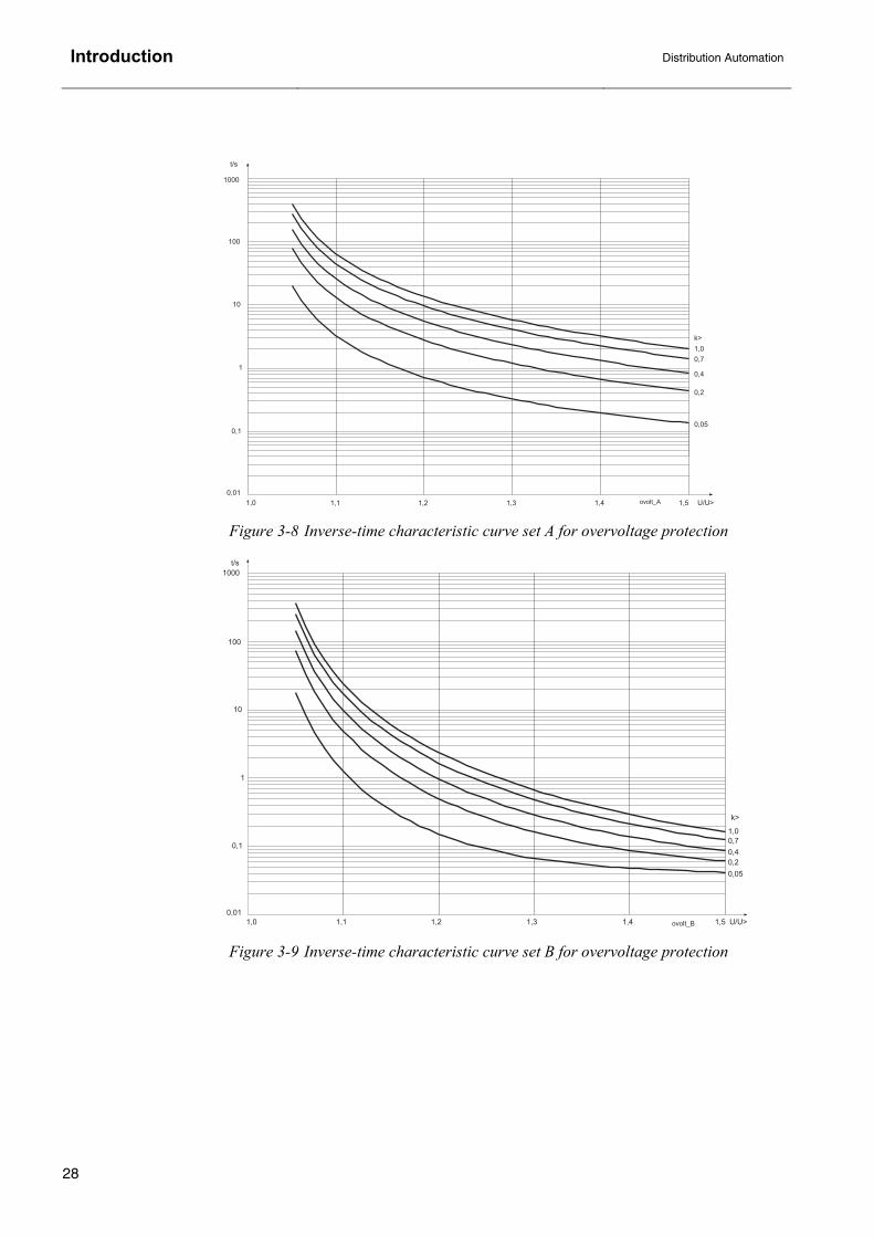
3. Inverse-time characteristics The inverse-time characteristics available in the current and voltage protection function blocks of RE_ 5_ _ are illustrated below. For more information about the inverse-time operation of a specific function block, refer to the corresponding function block manual.
0.05
0.1
0.2
0.3
0.4
0.5
0.60.70.80.91.0
k
1 2 3 4 5 7 8 9 10 20 I/I>60.02
0.03
0.04
0.05
0.06
0.070.080.090.1
0.2
0.3
0.4
0.5
0.6
0.7
0.80.9
1
2
3
4
5
6
789
10
20
30
40
50
60
70
t/s
NO
RM
INV
. 1 2 3 4 5 6 7 8 9 10 20 I/I>
0.05
0.1
0.2
0.3
0.4
0.5
0.6
0.70.80.91.0
k
0.02
0.03
0.04
0.05
0.06
0.070.080.090.1
0.2
0.3
0.4
0.5
0.6
0.7
0.80.9
1
2
3
4
5
6
789
10
20
70
60
50
40
30
t/s
VE
RY
INV
Figure 3-1 IEC inverse-time characteristic curve sets Normal inverse (left) and Very inverse (right) for current protection

Introduction
Distribution Automation
22
1 3 4 5 6 7 8 9 102 20 I/I>
0.05
0.1
0.2
0.3
0.4
0.6
0.8
1.0
k
0.02
0.03
0.04
0.05
0.06
0.070.080.090.1
0.2
0.3
0.4
0.5
0.6
0.7
0.80.9
1
2
3
4
5
6
789
10
20
30
40
70
60
50
t/s
EX
TR
INV
1 2 3 4 5 10 206 7 8 9 I/I>
0.05
0.1
0.2
0.3
0.4
0.5
0.6
0.70.80.91.0
k
0.2
0.3
0.4
0.5
0.6
0.70.80.9
1
2
3
4
5
6
7
89
10
20
30
40
50
60
708090
100
200
300
400
500
600
700
t/s
LTIM
EIN
V
Figure 3-2 IEC inverse-time characteristic curve sets Extremely inverse (left) and Long time inverse (right) for current protection

Distribution Automation
Introduction
23
1 2 3 4 5 6 7 8 9 10 20 I/I>
0.05
0.1
0.2
0.3
0.4
0.5
0.6
0.70.80.91.0
k
0.02
0.03
0.04
0.05
0.06
0.070.080.090.1
0.2
0.3
0.4
0.5
0.6
0.70.80.9
1
3
4
5
6
7
9
10
20
70
60
50
40
30
t/s
2
8
RI_
INV
0.6
0.7
0.8
0.9
1.0
k
1 2 3 5 7 8 9 10 20 I/I>60.02
0.03
0.04
0.05
0.06
0.070.080.090.1
0.2
0.3
0.4
0.5
0.6
0.7
0.80.9
1
2
3
4
5
78
10
20
30
40
50
60
70
t/s
30 40
6
9
0.05
4
0.1 0.2 0.4 0.50.3
RD
_IN
V
Figure 3-3 Special inverse-time characteristic curve sets RI-type inverse (left) and RD-type inverse (right) for current protection

Introduction
Distribution Automation
24
Figure 3-4 IEEE inverse-time characteristic curve sets Extremely inverse (left) and Very inverse (right) for current protection
1 2 3 4 5 6 7 8 9 10 200.05
0.060.070.080.090.1
0.2
0.3
0.4
0.5
0.60.70.80.9
1
2
3
4
5
6789
10
20
30
40
50
60708090
100
200
I/I>
t/s
n=0.5 n=1.0
n=2.0
n=3.0
n=5.0
n=7.0
n=9.0
n=11.0n=13.0n=15.0
1 2 3 4 5 6 7 8 9 10 200.02
0.03
0.04
0.05
0.060.070.080.090.1
0.2
0.3
0.4
0.5
0.60.70.80.9
1
2
3
4
5
6789
10
20
30
40
50
60708090
100
I/I>
t/s
n=0.5
n=1.0
n=2.0
n=3.0
n=5.0
n=7.0
n=9.0
n=11.0n=13.0n=15.0

Distribution Automation
Introduction
25
Figure 3-5 IEEE inverse-time characteristic curve sets Inverse (left) and Short time inverse (right) for current protection
1 2 3 4 5 6 7 8 9 10 200.05
0.06
0.070.080.090.1
0.2
0.3
0.4
0.5
0.6
0.70.80.9
1
2
3
4
5
6
789
10
20
30
40
I/I>
t/s
n=0.5
n=1.0
n=2.0
n=3.0
n=5.0
n=7.0
n=9.0
n=11.0
n=13.0
n=15.0
1 2 3 4 5 6 7 8 9 10 200.05
0.06
0.070.080.090.1
0.2
0.3
0.4
0.5
0.6
0.70.80.9
1
2
3
4
5
6
789
10
20
30
40
I/I>
t/s
n=0.5 n=1.0n=2.0
n=3.0
n=5.0
n=7.0
n=9.0
n=11.0
n=13.0
n=15.0

Introduction
Distribution Automation
26
Figure 3-6 IEEE inverse-time characteristic curve sets Short Time Extremely Inverse (left) and Long Time Extremely Inverse (right) for current protection
1 2 3 4 5 6 7 8 9 10 200.05
0.06
0.070.080.090.1
0.2
0.3
0.4
0.5
0.6
0.70.80.9
1
2
3
4
5
6
789
10
20
30
40
I/I>
t/s
n=0.5 n=1.0 n=2.0n=3.0 n=5.0n=7.0
n=9.0
n=11.0
n=13.0n=15.0
1 2 3 4 5 6 7 8 910 200.1
0.2
0.3
0.4
0.50.60.70.80.9
1
2
3
4
56789
10
20
30
40
5060708090
100
200
300
400
500600700800900
1000
2000
I/I>
t/s
n=0.5
n=1.0
n=2.0
n=3.0
n=5.0
n=7.0
n=9.0n=11.0n=13.0n=15.0

Distribution Automation
Introduction
27
Figure 3-7 IEEE inverse-time characteristic curve sets Long Time Very Inverse (left) and Long Time Inverse (right) for current protection
1 2 3 4 5 6 7 8 910 200.1
0.2
0.3
0.4
0.50.60.70.80.9
1
2
3
4
56789
10
20
30
40
5060708090
100
200
300
400
500600700800900
1000
2000
I/I>
t/s
n=0.5
n=1.0
n=2.0
n=3.0
n=5.0
n=7.0
n=9.0n=11.0n=13.0n=15.0
1 2 3 4 5 6 7 8 9 10 200.1
0.2
0.3
0.4
0.50.60.70.80.9
1
2
3
4
56789
10
20
30
40
5060708090
100
200
300
400
500600
I/I>
t/s
n=0.5
n=1.0
n=2.0
n=3.0
n=5.0
n=7.0
n=9.0
n=11.0n=13.0n=15.0
Introduction
Distribution Automation
28
Figure 3-8 Inverse-time characteristic curve set A for overvoltage protection
Figure 3-9 Inverse-time characteristic curve set B for overvoltage protection

Distribution Automation
Introduction
29
Figure 3-10 Inverse-time characteristic curve set C for undervoltage protection

Introduction
Distribution Automation
30
4. Function block names and categories in alphabetical order ABS Standard; numeric
ADD Standard; arithmetic
AND Standard; bitwise operation
AR5Func Protection
BITGET Standard; bitwise operation
BITSET Standard; bitwise operation
BCD2INT Standard; type conversion
BOOL_TO_BYTE Standard; type conversion
BOOL_TO_DINT Standard; type conversion
BOOL_TO_DWORD Standard; type conversion
BOOL_TO_INT Standard; type conversion
BOOL_TO_REAL Standard; type conversion
BOOL_TO_SINT Standard; type conversion
BOOL_TO_UDINT Standard; type conversion
BOOL_TO_UINT Standard; type conversion
BOOL_TO_USINT Standard; type conversion
BOOL_TO_WORD Standard; type conversion
BOOL2INT Standard; type conversion
BYTE_TO_DWORD Standard; type conversion
BYTE_TO_WORD Standard; type conversion
CMBWEAR1 Condition monitoring
CMBWEAR2 Condition monitoring
CMCU3 Condition monitoring
CMGAS1 Condition monitoring
CMGAS3 Condition monitoring
CMSCHED Condition monitoring
CMSPRC1 Condition monitoring
CMTCS1 Condition monitoring
CMTCS2 Condition monitoring
CMTIME1 Condition monitoring
CMTIME2 Condition monitoring
CMTRAV1 Condition monitoring
CMVO3 Condition monitoring
CO3DC1 Control

Distribution Automation
Introduction
31
CO3DC2 Control
COCB1 Control
COCB2 Control
COCBDIR Control
CODC1 Control
CODC2 Control
CODC3 Control
CODC4 Control
CODC5 Control
COIND1 Control
COIND2 Control
COIND3 Control
COIND4 Control
COIND5 Control
COIND6 Control
COIND7 Control
COIND8 Control
COLOCAT Control
COLTC Control
COMH Standard; comparison
COPFC Control
COSW1 Control
COSW2 Control
COSW3 Control
COSW4 Control
CTD Standard; counter
CTU Standard; counter
CTUD Standard; counter
CUB1Cap Protection
CUB3Cap Protection
CUB3Low Protection
DATE_TO_UDINT Standard; type conversion
DEF2High Protection
DEF2Inst Protection
DEF2Low Protection
Diff3 Protection
Diff6G Protection
Diff6T Protection

Introduction
Distribution Automation
32
DINT_TO_INT Standard; type conversion
DINT_TO_REAL Standard; type conversion
DINT_TO_SINT Standard; type conversion
DIV Standard; arithmetic
DOC6High Protection
DOC6Inst Protection
DOC6Low Protection
DWORD_TO_BYTE Standard; type conversion
DWORD_TO_WORD Standard; type conversion
EQ Standard; comparison
F_TRIG Standard; edge detection
Freq1St_ Protection
FuseFail Protection
GE Standard; comparison
GRAY2INT Standard; type conversion
GT Standard; comparison
INDRESET General
Inrush3 Protection
INT_TO_DINT Standard; type conversion
INT_TO_REAL Standard; type conversion
INT2BOOL Standard; type conversion
LE Standard; comparison
LIMIT Standard; selection
LT Standard; comparison
MAX Standard; selection
MEAI1…8 Measurement
MEAO1…4 Measurement
MECU1A Measurement
MECU1B Measurement
MECU3A Measurement
MECU3B Measurement
MEDREC16 Measurement
MEFR1 Measurement
MEPE7 Measurement
MEVO1A Measurement
MEVO1B Measurement
MEVO3A Measurement
MEVO3B Measurement

Distribution Automation
Introduction
33
MIN Standard; selection
MMIALAR1 Control
MMIALAR2 Control
MMIALAR3 Control
MMIALAR4 Control
MMIALAR5 Control
MMIALAR6 Control
MMIALAR7 Control
MMIALAR8 Control
MMIDATA1 Control
MMIDATA2 Control
MMIDATA3 Control
MMIDATA4 Control
MMIDATA5 Control
MMIWAKE General
MotStart Protection
MOVE Standard; arithmetic
MUL Standard; arithmetic
MUX Standard; selection
NAT2INT Standard; type conversion
NE Standard; comparison
NEF1High Protection
NEF1Inst Protection
NEF1Low Protection
NOC3High Protection
NOC3Inst Protection
NOC3Low Protection
NOT Standard; bitwise operation
NPS3High Protection
NPS3Low Protection
NUC3St1 Protection
NUC3St2 Protection
OE1Low Protection
OE1High Protection
OL3Cap Protection
OPOW6St1 Protection
OPOW6St2 Protection
OPOW6St3 Protection

Introduction
Distribution Automation
34
OR Standard; bitwise operation
OV3High Protection
OV3Low Protection
PQCU3H Power quality
PQVO3H Power quality
PREV3 Protection
PSV3St1 Protection
PSV3St2 Protection
R_TRIG Standard; edge detection
REAL_TO_DINT Standard; type conversion
REAL_TO_INT Standard; type conversion
REAL_TO_SINT Standard; type conversion
REAL_TO_UDINT Standard; type conversion
REAL_TO_UINT Standard; type conversion
REAL_TO_USINT Standard; type conversion
REF1A Protection
REF4A Protection
REF4B Protection
ROV1High Protection
ROV1Inst Protection
ROV1Low Protection
RS Standard; bistable
RS_D Standard; bistable
SCVCSt1 Protection
SCVCSt2 Protection
SEL Standard; selection
SINT_TO_DINT Standard; type conversion
SINT_TO_INT Standard; type conversion
SINT_TO_REAL Standard; type conversion
SR Standard; bistable
SUB Standard; arithmetic
SWGRP1…20 General
TIME_TO_REAL Standard; type conversion
TIME_TO_TOD Standard; type conversion
TIME_TO_UDINT Standard; type conversion
TOD_TO_REAL Standard; type conversion
TOD_TO_TIME Standard; type conversion
TOD_TO_UDINT Standard; type conversion

Distribution Automation
Introduction
35
TOF Standard; timer
TOL3Cab Protection
TOL3Dev Protection
TON Standard; timer
TP Standard; timer
TRUNC_REAL_TO_DINT Standard; type conversion
TRUNC_REAL_TO_INT Standard; type conversion
TRUNC_REAL_TO_SINT Standard; type conversion
TRUNC_REAL_TO_UDINT Standard; type conversion
TRUNC_REAL_TO_UINT Standard; type conversion
TRUNC_REAL_TO_USINT Standard; type conversion
UDINT_TO_REAL Standard; type conversion
UDINT_TO_UINT Standard; type conversion
UDINT_TO_USINT Standard; type conversion
UE6High Protection
UE6Low Protection
UI6Low Protection
UI6High Protection
UINT_TO_BOOL Standard; type conversion
UINT_TO_REAL Standard; type conversion
UINT_TO_UDINT Standard; type conversion
UINT_TO_USINT Standard; type conversion
UPOW6St1 Protection
UPOW6St2 Protection
UPOW6St3 Protection
USINT_TO_REAL Standard; type conversion
USINT_TO_UDINT Standard; type conversion
USINT_TO_UINT Standard; type conversion
UV3High Protection
UV3Low Protection
VOC6High Protection
VOC6Low Protection
WORD_TO_BYTE Standard; type conversion
WORD_TO_DWORD Standard; type conversion
XOR Standard; bitwise operation