1n5555-1n5558 - digitron semiconductors high-reliability discrete products and engineering services...
TRANSCRIPT

High-reliability discrete productsand engineering services since 1977
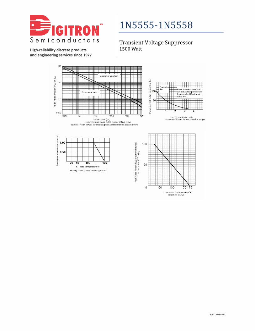
1N5555-1N5558Transient Voltage Suppressor1500 Watt
Rev. 20160527
FEATURES: Available as “HR” (high reliability) screened per MIL-PRF-19500, JANTX level. Add “HR” suffix to base part number Available Non-RoHS (standard) or RoHS compliant (add PBF suffix)
MAXIMUM RATINGS1500 Watts for 10/1000µs with repetition rate of 0.01% or less* at lead temperature (TL) 25°C
Operating and Storage Temperatures -65 to +175°C
Thermal Resistance 50°C/W junction to lead at 0.375” from body or 110°C/W junction to ambient when mountedon FR4 PC board with 4 mm2 copper pads and track width 1mm, length 25mm
DC Power Dissipation * 1 Watt @ TL = 25°C 3/8 from body
Forward Surge Current 200 Amps for 8.3 ms half-sine wave @ TA = 25°C
Solder Temperatures 260°C for 10 s (maximum)* TVS devices are not typically used for dc power dissipation and are instead operated at or less than their rated standoff voltage (VWM) except for transients thatbriefly drive the device into avalanche breakdown (VBR to VC region).
ELECTRICAL CHARACTERISTICS
MinimumBreakdown
Voltage
TestCurrent
RatedStandoffVoltage
Maximum(RMS)
ReverseVoltage
MaximumStandbyCurrent
MaximumPeak
ReverseVoltage
MaximumPeak Pulse
Current
MaximumTemperature
Coefficient
V(BR) @ I(BR) I(BR) VWM VWM(RMS) ID @ VWM VC @ IPP IPP αV(BR)
Type(note 1)
V mA V V µA V A %/°C
1N5555 33.0 1.0 30.5 21.5 5 47.5 32 +.093
1N5556 43.7 1.0 40.3 28.5 5 63.5 24 +.094
1N5557 54.0 1.0 49.0 34.5 5 78.5 19 +.096
1N5558 191.0 1.0 175 124.0 5 265.0 5.7 +.100Note 1: A TVS is normally selected according to the rated “Standoff Voltage” VWM that should be equal to or greater than the dc or continuous peak operatingvoltage level.
SYMBOLS AND DEFINITIONSVWM Standoff Voltage: Applied Reverse Voltage to assure a nonconductive condition
V(BR) Breakdown Voltage: This is the Breakdown Voltage the device will exhibit at 25°C
VC
Maximum Clamping Voltage: The maximum peak voltage appearing across the TVS when subjected to the peak pulse current ina one millisecond time interval. The peak pulse voltage is the combination of voltage rise due to both the series resistance andthermal rise and positive temperature coefficient (αV(BR))
IPP Peak Pulse Current: The peak current during the impulse
PPP Peak Pulse Power: The pulse power as determined by the product of VC and IPP
ID Standby Current: The current at the standoff voltage (VWM)
I(BR) Breakdown Current: The current used for measuring breakdown voltage (V(BR))

High-reliability discrete productsand engineering services since 1977
1N5555-1N5558Transient Voltage Suppressor1500 Watt
Rev. 20160527
MECHANICAL CHARACTERISTICSCase DO-13
Marking Alpha-numeric, body painted
Polarity Cathode band
High-reliability discrete productsand engineering services since 1977
1N5555-1N5558Transient Voltage Suppressor1500 Watt
Rev. 20160527