1st edition price $2 - chartertoconductor.com
TRANSCRIPT

DIESEL LOCOMOTIVE
OPERATING MANUAL NO. 2314
FOR
ROAD SWITCHING LOCOMOTIVE
MODEL SD7
With Vapor Steam Generator
1st Edition
Price $2.50
ELECTRO-MOTIVE DIVISION General Motors Corporation
LA GRANGE, ILLINOIS, U.S.A. PRINTED IN U.S.A.

INTRODUCTION
As a publication of general information and instruction, this manual has been written for the benefit of Railroad personnel concerned with the operation of the SD7 six motor road switcher locomotive. Coverage of the most commonly used "extras" as well as basic (standard) equipment is included.
Sections 1 and 2 of this manual are devoted to a description of the locomotive, normal operation over the road, and special conditions and problems during operation. Section 3 describes the electrical equipment. Section 4 consists of a general description of the cooling, lubricating oil, fuel oil, and air systems along with other necessary information for operation of the locomotive. Section 5 consists of a reprint of the TS6 "On-the-Road Trouble-Shooting" booklet. Section 6 covers the Vapor Heating Corporation OK-4625 steam generator.
This manual also includes coverage of Dynamic Braking, but is so written that on locomotives not equipped with dynamic brakes, the subject may be disregarded without causing any conflict in operating instructions.
Principal articles of each section are numbered consecutively for ready reference, as is each page of the section. Articles and pages are numbered in the 100 series type of numbering. A page in the 400's is in Section 4 as is any article numbered in the 400's.

GENERAL SD7-0-1052
GENERAL DATA
SD7 DIESEL LOCOMOTIVE Weight Fully Loaded
Light Underframe (Approx.). . . . . . 300,000 lbs. Heavy Underframe (Approx.) . . . . . 360,000 lbs.
Fuel Capacity (without steam gen.) . . . . 2400 gal. Fuel Capacity (with steam gen.) . . . . . 1200 gal. Lubricating Oil Capacity . . . . . . . . . 200 gal. Cooling Water Capacity . . . . . . . . . 260 gal. Steam Generator Water Capacity (if used) . 1200 gal. Gear Ratios and Maximum Speeds:
65/12..........55 MPH 60/17..........77 MPH 62/15..........65 MPH 59/18..........83 MPH 61/16..........71 MPH 58/19..........89 MPH
Sand Capacity . . . . . . . . . . . . . . 50 cu. ft. Number of Drivers . . . . . . . . . . . . 6 pair Wheel Diameter . . . . . . . . . . . . . 40" Weight on Drivers . . . . . . . . . . . . . 100% Truck Centers . . . . . . . . . . . . . . 35' 0" Truck - Rigid Wheel Base . . . . . . . . . 13' 7" Minimum Curve Radius . . . . . . . . . . 250' Overall Length Over Couplers . . . . . . . 60' 8" Maximum Height Above Rail . . . . . . . . 15' 0" Maximum Width Over Handholds . . . . . . 10' 8"
SD7-0-1052 GENERAL
TABLE OF CONTENTS
Page SECTION 1 - GENERAL DESCRIPTION 100 Diesel Engine 100 Main Generator and Alternator 101 Traction Motors 101 Auxiliary Equipment 103 Operating Controls 104
Throttle Lever 104 Reverse Lever 104 Selector Lever 106 Mechanical Interlocks On The Controller 106 Hump Speed Control 107 Dynamic Brake 107
Air Brake Equipment 108
Independent Brake Valve 110 K-2-A Rotair Valve 110 Safety Control Foot Pedal 110
Control And Operating Devices Cab Mounted 110
Electrical Control Cabinet 110 Ground Relay 111 Engine Control Panel 111 Isolation Switch 111 Headlight Control Switches 112 Unit Selector Switch 113 Alarm Bell and Signal Lights 113 Hot Engine Warning Light 113 No Power Warning Light 113 Boiler Stopped Warning Light 113 PCS Indicating Light 113 "PC" Switch 114 Wheel Slip And Dynamic Brake WarningLight 114 Switches 114

GENERAL SD7-0-1052
Page
Air Gauges 116 Load Indicating Meter 116 Sanding Valve 117 Speed Recorder-Locomotive Overspeed Control 117 Windshield Wipers 117 Horn Valve 117 Locomotive Bell Valve 118 Cab Heating And Ventilating 118
Engine Room 119
Engine Governor 120 Layshaft Manual Control Lever 121 Engine Overspeed Trip 122 Load Regulator 122 Control Air Pressure Regulator 122
Miscellaneous Equipment 123
Classification Lights 123 Number Boxes 123 Trucks 123 Hand Brake……. 124
SECTION 2 - OPERATION 200 When Boarding The Locomotive 200 Precautions Before Starting Engine 204 To Start Engine 207 Placing An Engine On The Line 208 To Stop E ngine 208 Securing Locomotive For Layover 209 Precautions Before Moving Locomotive 209 Handling Light Locomotives 209 Pumping Up Air 210 Starting A Train 210 Automatic Sanding In Power 213 Acceleration Of A Train 213 Slowing Down Because Of A Grade 214 Operating In Short Time Overload Zone 214
SD7-0-1052 GENERAL
Page Braking 214
Air Braking With Power 214 Dynamic Brake Operation 216 Dynamic Brake Wheel Slide Control 219 Hump Speed Control 219
Miscellaneous Operating Instructions 221
Changing Operating Ends 221 Multiple Unit Operation 223 Operating With A Helper Locomotive 223 Operating As A Helper Locomotive 224 Doubleheading 225 Operation Over Railroad Crossings 225 Running Through Water 225 Freezing Weather Precautions 226 Splitting And Joining Units 227 Towing Locomotive 227 Recovery Of Brake After Penalty Application 228 Setting "PC" Switch 229 Ground Relay 229 Wheel Slip Control 229 Indication Of A Pair Of Wheels Sliding 230
SECTION 3 - ELECTRICAL EQUIPMENT 300 General Electrical Scheme 300 Main Generator 301 Traction Motors 302 Automatic Transition 303 Hump Speed Control 304 Wheel Slip Control 305 Dynamic Brake Wheel Slide Control 308 Reversing Locomotive 309 Load Regulator 309 Battery Field Contactor And Fusetron 310 Main Battery Switch 314 Battery Ammeter 314 Reverse Current Relay 314 Battery Charging Contactor 314

GENERAL SD7-0-1052
Page ELECTRICAL EQUIPMENT (Cont'd) Battery Charging Fusetron 314 Auxiliary Generator Field Fusetron 315 Voltage Regulator 315 Ground Relay 315 No AC Voltage Relay 316 SECTION 4 - COOLING, LUBRICATING OIL,
FUEL OIL AND AIR SYSTEMS
Cooling System Engineroom Winterization 400 Cab Heating And Ventilating 401 Operating Water Level 403
Lubricating Oil System 404 Oil Level 406 Adding Oil To System 407 Oil Pressure 407
Fuel Oil System 407
Fuel Flow 407 Fuel Tanks 408 Emergency Fuel Cutoff Valve 409
Air System 409
Air Compressor 409 Individual Compressor Control 412 Synchronized Compressor Control 413 Manual Air Compressor Control 414 Draining Of Air System 414
SECTION 5 - ON-THE-ROAD TROUBLE -SHOOTING 500 General 501 If Alarm Bells Ring 501 Engine Goes To Idle 508 Engine Stops 508 How To Start Engine 509
SD7-0-1052 GENERAL
Page The Engine Does Not Rotate When "Start" Button Is Pressed 510 The Engine Rotates But Does Not Start When "Start" Button Is Pressed 510 The Engine Does Not Speed Up When Throttle Is Opened 511 The Engine Speed Picks Up But Locomotive Does Not Move When
Throttle Is Opened 512 Battery Ammeter Shows Continual Discharge 512 PC Switch 513 Ground Relay 514 Starting Contactors 515 Engine Overspeed Trip 515 Lube Oil Button On Governor 516 Emergency Fuel Oil Cutoff Valve 516 Fuel Flow 516 Engine Speed Indicator 517 Control Air Pressure 517 Compressor Control 517 Cylinder Test Valves 518 Tying Up The Locomotive 519 SECTION 6 - STEAM GENERATOR MODEL OK-4625 600 Introduction 600 Description 600 Before Starting 603 To Fill 604 To Start 604 Standby Heating 606 Running Attention 607 To Shut Down The Steam Generator 608 Layover Operation 609 Freezing Weather Precautions 609 Trouble Shooting 610 Items To Report 614

NOTES
SD7-1-1052 DESCRIPTION
SECTION 1
GENERAL DESCRIPTION
A description and general location of equipment on the SD7
locomotive is given in this section.
A locomotive consists of one or more units rated at 1500 horsepower per unit. Depending upon the horsepower requirements a locomotive will consist of from 1 to 4 units.
Four major variations in locomotive models are available. In the designations SD7LH, SD7LL, SD7RH and SD7RL, the last letter indicates the general weight classification, light or heavy underframe, while the next to the last letter indicates air brake schedule, 24RL or 6BL. NOTE: Basically, the cab end of the SD7 locomotive is the front end.
Any reference to front or rear ends and left or right sides will be based on the normal basic arrangement. On request, con-trols may be relocated so that the long (hood) end is the front of the locomotive.
100 Diesel Engine The main generator and auxiliaries of these units are driven by a 16-cylinder V-type, 2 cycle, Model 567B Diesel engine. The cylinders have an 8-1/2" bore and a 10" stroke. The two banks of the engine are arranged with respect to each other at an angle of 45°.
The engine is started by temporarily using the direct coupled main generator as a starting motor. Current from a storage battery "motors" the main generator to rotate the engine.
- 100 -
DESCRIPTION SD7-1-1052 NOTE: In this manual, the word "engine" refers specifically to the
Diesel engine; the word "locomotive" refers to a consist of one or more units.
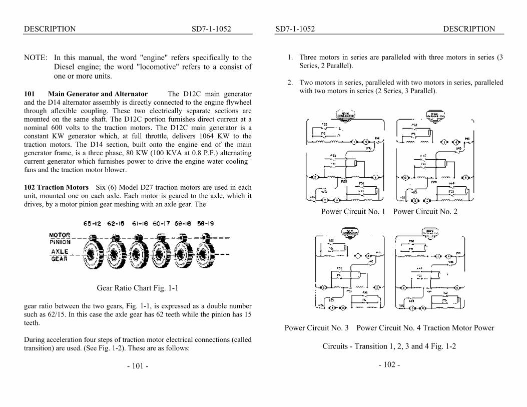
101 Main Generator and Alternator The D12C main generator and the D14 alternator assembly is directly connected to the engine flywheel through aflexible coupling. These two electrically separate sections are mounted on the same shaft. The D12C portion furnishes direct current at a nominal 600 volts to the traction motors. The D12C main generator is a constant KW generator which, at full throttle, delivers 1064 KW to the traction motors. The D14 section, built onto the engine end of the main generator frame, is a three phase, 80 KW (100 KVA at 0.8 P.F.) alternating current generator which furnishes power to drive the engine water cooling ' fans and the traction motor blower. 102 Traction Motors Six (6) Model D27 traction motors are used in each unit, mounted one on each axle. Each motor is geared to the axle, which it drives, by a motor pinion gear meshing with an axle gear. The
Gear Ratio Chart Fig. 1-1 gear ratio between the two gears, Fig. 1-1, is expressed as a double number such as 62/15. In this case the axle gear has 62 teeth while the pinion has 15 teeth. During acceleration four steps of traction motor electrical connections (called transition) are used. (See Fig. 1-2). These are as follows:
- 101 -
SD7-1-1052 DESCRIPTION
1. Three motors in series are paralleled with three motors in series (3 Series, 2 Parallel).
2. Two motors in series, paralleled with two motors in series, paralleled
with two motors in series (2 Series, 3 Parallel).
Power Circuit No. 1 Power Circuit No. 2
Power Circuit No. 3 Power Circuit No. 4 Traction Motor Power
Circuits - Transition 1, 2, 3 and 4 Fig. 1-2
- 102 -

DESCRIPTION SD7-1-1052
3. Same as the motor connection described in Item 2, but with the traction motor fields shunted.
4. Same as the motor connection described in Item 2, but with the
traction motor fields shunted to a greater extent than in transition 3.
103 Auxiliary Equipment Auxiliary equipment is driven
entirely by direct drive from the engine or by separate electric motors. Belt drives are not used. Locomotives with steam generators are equipped with an 18 KW auxiliary generator, those without have
A 10 KW auxiliary generator. The auxiliary generator is driven directly from the rear gear train of the engine through flexible couplings. This generator produces direct current at 74 volts to change the storage battery and supply the low voltage circuits for lighting, control, external main generator field excitation, fuel pump operation, etc.
A 25 HP A.C. electrically driven blower provides cooling air for the three traction motors in the rear truck. Cooling air for traction motors in the front truck is provided by a blower driven from an extension of the auxiliary generator armature shaft.
Four 9 HP electrically driven cooling
fans, controlled by thermostats, supply air for the engine cooling water radiators.
SD7 locomotives are basically equipped with a Gardner-Denver six cylin-der, two stage air compressor driven through a flexible coupling from the front end of the engine crankshaft. It is rated at 356 CFM at
800 RPM. Air Compressor Fig. 1-3
- 103 -
SD7-1-1052 DESCRIPTION
OPERATING CONTROLS
Three levers and two brake valve handles control the entire operation of the locomotive. These are the throttle, reverse and selector levers, mounted in the controller, and the independent and automatic brake valve handles. Units not equipped with dynamic brakes do not have a selector lever. See Fig. 1-4. 104 Throttle Lever This lever controls the speed of the engines and the train speed in normal operation. The position of the throttle is shown in the illuminated indicator above the lever. The throttle has ten positions, stop, idle and running speeds 1 to 8. Stop can be obtained by depressing the emergency stop button on the end of the throttle lever and pushing the throttle lever one step beyond idle position; this stops all engines. Idle position is as far forward as the throttle lever can be moved without depressing the emergency stop button. Each running notch on the throttle increases the engine speed in 75 RPM increments from 275 RPM at idle and Run 1, to 800 RPM at full throttle. Mechanical interlocks, to prevent the throttle from being opened more than one notch at a time, are not used on the SD7. The throttle may be closed completely with one motion in an emergency, but should be closed one notch at a time in normal operation. It may be opened as rapidly as desired PROVIDING OPERATING CONDITIONS AND TRAIN CONSIST PERMITS. This arrangement is of special value in "kicking" cars and while operating over the road on a "tight" schedule. 105 Reverse Lever The reverse lever may be moved ONLY when the locomotive is standing still. Direction of the locomotive is controlled by movement of this lever to the forward or reverse pos-ition. In neutral the power circuits will not close when the throttle is opened.
- 104 -

DESCRIPTION SD7-1-1052
1. Load Indicator 2. Horn Pull Cords 3. Air Gauges 4. Alarm Lights 5. Automatic Brake Valve 6. Sander Valve 7. Bell Ringer Valve 8. Independent Brake Valve 9. Control Switches (Circuit Breakers) 10. Speed Recorder 11. Throttle Lever 12. Selector Lever 13. Headlight Control - Dim And Bright 14. Reverse Lever
Engineman's Controls Fig. 1-4
- 105 -
SD7-1-1052 DESCRIPTION
The reverse lever can be removed from the control stand only when the lever is in the neutral position, the throttle is in "Idle" and the selector lever is in "Off." Removal of the reverse lever locks the opera-ting controls in the controller. Remove the reverse lever from all non-operating control stands. 106 Selector Lever All SD7 locomotives are basically equipped with automatic transition. Transition is FULLY AUTOMATIC, both forward and backward, and no provision is made basically for making transition manually. However, a selector lever is supplied for the purpose of controlling dynamic braking. An interlock in the controller prevents the throttle from being opened unless the selector lever is in either the Off or Run position.
On locomotives equipped with dynamic brakes moving the selector lever to the "Off" position does not establish any portion of the braking circuit. Moving the lever to the "B" position partially establishes the braking circuit. Moving the lever farther, to the right of "B," completes the circuit and increases the braking effort (see Art. 215 for dynamic brake operation). 107 Mechanical Interlocks On The Controller The levers on the control stand are interlocked so that:
1. The reverse lever can be operated only with the selector lever in either RUN or OFF position and the throttle at IDLE. Removing the reverse lever locks the throttle and selector levers.
2. Selector lever can be moved to "B" only with throttle in Idle
and the reverse lever in Forward or Reverse. 3. Selector lever can be moved between Off and Run only when
the throttle is in Idle or Stop.
- 106 -

DESCRIPTION SD7-1-1052
4. Selector lever cannot be moved when the throttle is above Idle. 5. Throttle lever can be advanced with selector lever in Off or Run. 6. Throttle lever in Stop locks against movement of reverse lever, but
the selector lever may be moved to any position. 7. Throttle can be moved to Stop with reverse and selector levers in any
position. 108 Hump Speed Control As an extra, some locomotives are equipped with a special main generator excitation control circuit to be used during humping operations. The manual control device, Fig. 1-5, for this circuit is mounted on top of the control stand. See Articles 217 and 304. 109 Dynamic Brake Some locomotives are provided with additional electrical equipment permitting a portion of the power developed by the momentum of the train to be converted into an effective negative power,
Hump Speed Control Fig. 1-5
- 107 -
SD7-1-1052 DESCRIPTION retarding the speed of the train. This feature is known as the dynamic brake and is especially useful as a holding brake, on descending grades.
The traction motor armatures, being geared to the axles, are rotating whenever the train is moving. When using the dynamic brake, electrical circuits are set up which change the traction motors into generators. Since it takes power to rotate a generator this action retards the train. The power thus generated is dissipated in resistors, called grids, which are cooled by motor driven fans. The grids and fans are located in the top of the carbody. See Article 215.
AIR BRAKE EQUIPMENT
The 6 BL brake equipment is basic on SD7 locomotives. Air brake gauges are located in the engineman's control panel in front of the enginemen. The cab air brake equipment consists of the standard H6 automatic brake valve, and a self-lapping independent brake valve. The automatic brake valve has 6 positions, release, running, holding, lap, service and emergency and can be furnished with the brake valve handle removable in the running position. The handle should be removed from all non-operating control stations.
The brake valve also contains a sanding operating valve and a bell ringer valve. The feed valve and double heading cock are mounted below the independent brake valve.
The equipment and operation of the 6 BL brake is practically the same as that of the 6 ET brake, with the exception of a self-lapping independent brake valve, and a few other modifications.
As all enginemen are more or less familiar with the operation of the 6 ET brake, no detailed operation of the 6 BL will be included. See Article 214.
- 108 -

DESCRIPTION SD7-1-1052
With the number of combinations and modifications possible, no attempt will be made to enumerate them here, as it would be far beyond the scope of this manual to do so. Special instructions for special applications may be had from locomotive manufacturer upon request by the customer.
The 24 RL brake is generally applied to locomotives intended for main and branch line service. Operating instructions are covered briefly in this manual. More definite instructions may be obtained by contacting the proper railroad officials.
The air brake gauges are located on the instrument panel to the left of the engineman. In general, the cab air brake equipment (24 RL) consists of the automatic brake valve I the independent brake valve and the K-2-A Rotair Valve, a manually operated valve having four positions. The automatic brake valve handle has 6 positions - release, running, first service, lap, service and emergency; and may be of the rigid or hinged handle type. The automatic brake valve handle (rigid or hinged handle) is removable in the running position. The handle should be removed from all nonoperating control stations. The hinged handle, if required by the railroad, is used to suppress a safety control from the foot pedal (if used) by depressing the handle to a horizontal position. On some railroads a sanding bail provides sanding by further depressing the handle. The brake valve, Fig. 2-1 also contains:
1. Brake valve cutout cock, located on the filling piece portion. 2. Safety control cutout cock, located on the service application
portion. 3. First service position cock. 4. Full release selector cock.
- 109 -
SD7-1-1052 DESCRIPTION 110 Independent Brake Valve The S-40-F independent brake valve handle has two positions, release and full application, with the application zone between the two positions. The brake valve is of the self-lapping type which automatically laps off the flow of air and maintains brake cylinder pressure when the application pressure reaches the value corresponding to the position of the brake valve handle in the application zone. Locomotive brakes may be released after automatic application by depressing the independent brake valve handle in release position. 111 K-2-A Rotair Valve The four positions of the K-2-A rotair valve are "FRGHT," "FRGHT LAP" "PASS LAP" and "PASS." It is located inside the engineman's control panel stand and is accessible through a door in the back side of the stand. See Art. 200, Item B-6, for handling of this valve. 112 Safety Control Foot Pedal The safety control foot pedal (if used) is located in front of the engineman's seat. On locomotives equipped with the DS24-H brake valve, having the hinged automatic brake valve handle, the handle provides an alternate control when it is depressed sufficiently to just contact the sanding bail. Either the pedal or the automatic brake valve handle must be kept depressed at all times except when the locomotive is stopped and the locomotive brakes are applied (30 pounds or more brake cylinder pressure). If both the foot pedal and the automatic brake valve are released, a penalty application of the brakes will result.
CONTROL AND OPERATING DEVICES CAB MOUNTED
113 Electrical Control Cabinet The electrical control cabinet contains the various contactors, relays, and other equipment necessaryfor the electrical and electro-pneumatic control of the unit.
- 110 -

DESCRIPTION SD7-1-1052 It forms the rear wall of the cab and is accessible from both the cab and engine room sides. 114 Ground Relay The ground relay is located in the cab side of the electrical cabinet. A reset button protrudes through the cabinet door. 115 Engine Control Panel This panel is mounted on the rear wall of the cab above the electrical cabinet. Fig. 1-6 shows arrangement of the switches, gauges and alarm signals. Functions and features of the isolation, headlight control and unit selector switches are given in the following articles.
Engine Control Panel Fig. 1-6
116 Isolation Switch This switch has two positions, START (horizontal) and RUN (vertical). In START position, the power plant is disconnected from throttle control and engine speed is reduced to idle. Power contactors in the electrical control cabinet will not operate when control levers are moved. In dynamic braking, the unit will not exert retarding effort. No Power and Ground Indicating Lights and alarm are inoperative. START and STOP buttons are effective only with isolation switch in START position.
- 111 -
SD7-1-1052 DESCRIPTION
The isolation switch must be firmly in the RUN position to obtain power from the unit. The switch should be opened and closed only with the engine at idle speed or stopped. Use the manual layshaft lever to bring the engine to idle or stop when the locomotive is under power or in dynamic braking. If the isolation switch is in the START position do not place it in RUN while operating in dynamic braking. 117 Headlight Control Switches Twin sealed beam headlights are controlled by front and rear OFFON switches on the engineman's control panel. A dimming switch, Fig. 1-7, is installed convenient to the engineman.
On SD7 locomotives equipped for multiple unit operation, a remote headlight switch, Fig. 1-8, is located on the engine control panel above the electrical cabinet. The switch has four positions, and should be placed in the position corresponding to the operation as described on the name plate. In case an SD7 is being used as the middle unit in a 3 or 4 unit consist, the remote head light switch should be placed in the single unit position.
Headlight Dimming Switch Remote Headlight Switch Fig. 1-8
-112-
DESCRIPTION SD7-1-1052 118 Unit Selector Switch
The unit selector switch, supplied on locomotives equipped with dynamic braking, is located on the engine control panel. It has four positions (1, 2, 3 and 4) and should be set to correspond with the number of units in the locomotive. This switch, Fig. 1-6, should be set before leaving the terminal and must not be changed even if an engine is isolated enroute. Change this switch only if the locomotive consist is changed. 119 Alarm Bell and Signal Lights
Signal lights and the alarm bell are located on the engine con-trol panel, Fig. 1-6, above the electrical cabinet. These lights are to indicate Hot Engine, Boiler Stopped, and No Power. In case of an alarm, the bell will ring in all units but a light will be lit only in the unit affected. 120 Hot Engine Warning Light
Engine Water discharge temperatures in excess of 208° F will cause the RED hot engine warning light to light and the alarm bell to ring.
121 No Power Warning Light Any condition which causes the NVR (no AC voltage relay) to
drop out will turn on the PURPLE warning light and sound the alarm bell. The engine speed will be reduced to Idle. If the throttle is in Run 5 or 6, the engine will stop.
122 Boiler Stopped Warning Light Any condition which causes the steam generator to stop will
cause the GREEN light to light and alarm bell to ring. 123 PCS Indicating Light
This WHITE indicating light lights whenever the PC switch is tripped. The switch automatically resets itself provided throttle is returned to Idle and control of the brake is recovered.
- 113 -
SD7-1-1052 DESCRIPTION 124 "PC" Switch
The pneumatic control (PC)switch (often called the power cutoff switch) is an air operated electric switch that is tripped by any "penalty" air application, automatically shutting off the power output of the locomotive. When this switch is tripped, it de-energizes the ER relay, reducing the engines to idle speed and shuts off all fuel pumps. If the. throttle is left in the 5th or 6th notch when the PC switch is tripped, the engines will stop. A white indicating (PCS) light on the engineman's control panel, Fig. 1-9, will be lit whenever the switch is tripped.
The PC switch automatically resets itself provided that (1) the throttle is returned to idle, and (2) control of the brake is recovered. (See Art.228 for method of recovering control of the brake). When this has been accomplished, the PCS indicating light will go out. 125 Wheel Slip And Dynamic Brake Warning Light
If the locomotive is equipped with dynamic braking this WHITE light will serve as both the wheel slip and the dynamic brake warning light. The lighting of this light during power operation indicates the wheels are slipping.
When using the dynamic brake, the lighting of this light will indicate that the dynamic braking grids of one or more of the units in the consist is, at the moment, overloaded. Refer to Art. 215. 126 Switches
The engineman's control panel contains circuit breaker type switches, Fig. 1-9, for control, light and accessory circuits. Name plates for each switch are illuminated by lights contained behind the panel. Rheostat type light switches operate these lights as well as the gauge and load meter lights. The distribution panel, Fig. 1-10, located on the right side of the electrical control cabinet in the rear wall of the
-114-

DESCRIPTION SD7-1-1052
Engineman's Control Panel Fig. 1-9
Distribution Panel Fig. 1-10
- 115 -
SD7-1-1052 DESCRIPTION cab has a number of main switches all of which are to be closed during normal operation. 127 Air Gauges These are standard gauges. Each is clearly labeled as to its function. 128 Load Indicating Meter This meter, Fig.1-11, is an accurate guide to the load and pulling force of the locomotive. The meter is connected into the leads of the No. 2 motor. Since the amperage is the same in all motors, each motor receives the amount of current shown on the meter. The dial of the meter is graduated into amperes from 0 at the left to 1500 amperes at the extreme right of the scale.
A name plate is mounted below the load meter dial showing the time it is permissible to operate at different stages of overload. These "short time overload" ratings are accumulative, which means that it is permissible to operate the full time of each rating consecutively or in any combination. This name plate also shows the
Load Indicator Meter Fig. 1-11
- 116 -
DESCRIPTION SD7-1-1052 maximum amount of amperage permissible to use when operating the dynamic brake, should the locomotive be so equipped. 129 Sanding Valve
On locomotives equipped with the hinged automatic brake valve handle, sanding is accomplished by depressing the lever beyond the safety control position previously described. This movement operates the sanding bail which opens a port to supply air to the sanding equipment. On locomotives having a rigid handle on the automatic brake valve, an independent sanding valve is installed. This lever is operated by pushing the lever forward or backward until it latches. Refer to Art. 210, Automatic Sanding In Power. 130 Speed Recorder-Locomotive Overspeed Control
The speed recorder, located ahead of the controller, is a hydraulically operated speed indicator with a speed recording tape and an odometer. It is driven from the number 2 or center axle of the lead truck through a flexible cable. It contains a maximum speed device which will initiate a full service application of the brakes and trip the PC switch when the maximum speed setting is exceeded. On some railroads, instead of a full service application, the brakes go into emergency. 131 Windshield Wipers
Each of the four windshield wipers are controlled by a valve, two of which are located above the engineman's side window and two above the window on the fireman's side of the cab. The wipers should not be run on a dry window as they may scratch the glass. 132 Horn Valve
The horns (front and rear) are operated by air valves, which are controlled by pull-cords, above the control stand. The horn shutoff valve is located outside the electrical control cabinet on the fireman's side.
- 117 -
SD7-1-1052 DESCRIPTION 133 Locomotive Bell Valve
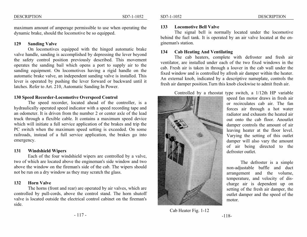
The signal bell is normally located under the locomotive behind the fuel tank. It is operated by an air valve located at the en-gineman's station. 134 Cab Heating And Ventilating
The cab heaters, complete with defroster and fresh air ventilator, are installed under each of the two fixed windows in the cab. Fresh air is taken in through a louver in the cab wall under the fixed window and is controlled by afresh air damper within the heater. An external knob, indicated by a descriptive nameplate, controls the fresh air damper position.Turn this knob clockwise to admit fresh air.
Controlled by a rheostat type switch, a 1/12th HP variable speed fan motor draws in fresh air or recirculates cab air. The fan forces air through a hot water radiator and exhausts the heated air out onto the cab floor. Anoutlet damper controls the amount of air leaving heater at the floor level. Varying the setting of this outlet damper will also vary the amount of air being directed to the defroster outlet.
The defroster is a simple
non-adjustable baffle and duct arrangement and the volume, temperature, and velocity of dis-charge air is dependent up on setting of the fresh air damper, the outlet damper and the speed of the motor.
Cab Heater Fig. 1-12 -118-
DESCRIPTION SD7-1-1052
Cab heater water is taken from between the engine banks near the rear of the engine. A shutoff valve in this line is located near the engine blower. This valve must always be open during freezing weather. Drain valves are locatedunder the locomotive frame at the left side of the cab and in the line to the toilet water tank.
After the water passes through the heater, it passes through a heat exchanger in the toilet water tank and then returns to the engine cooling system.
Steam tracer lines are lagged to heater water supply and return lines throughout their run in the locomotive frame box section under the outside engine room catwalks. This tracer line exhausts into the cab heater piping under the cab floor near the heaters to keep them from freezing during engine shutdowns. As the steam in the tracer line eventually condenses, the "G" valve must be open when steam is used
to keep the engine cooling and cab heating system from freezing. Tracer line steam is supplied from the engine side of the engine steam admission valve; therefore, steam ad-mitted for the engine protects the cab heater system.
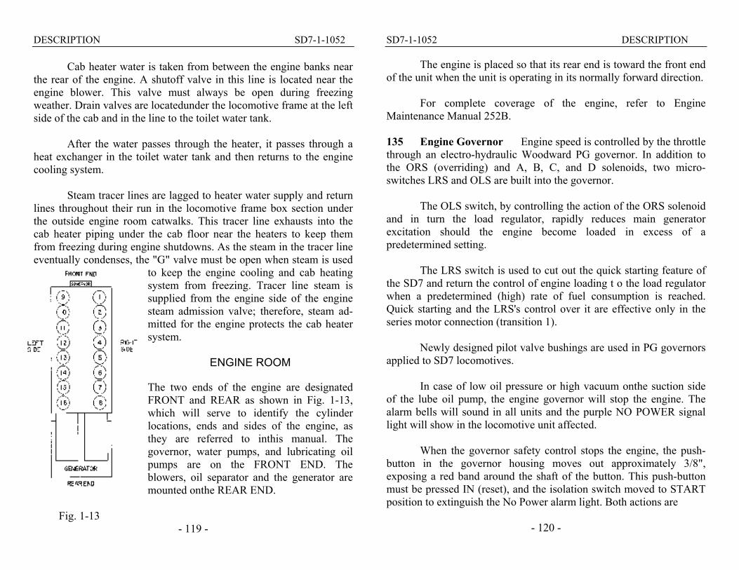
ENGINE ROOM The two ends of the engine are designated FRONT and REAR as shown in Fig. 1-13, which will serve to identify the cylinder locations, ends and sides of the engine, as they are referred to inthis manual. The governor, water pumps, and lubricating oil pumps are on the FRONT END. The blowers, oil separator and the generator are mounted onthe REAR END.
Fig. 1-13
- 119 -
SD7-1-1052 DESCRIPTION
The engine is placed so that its rear end is toward the front end of the unit when the unit is operating in its normally forward direction.
For complete coverage of the engine, refer to Engine Maintenance Manual 252B. 135 Engine Governor Engine speed is controlled by the throttle through an electro-hydraulic Woodward PG governor. In addition to the ORS (overriding) and A, B, C, and D solenoids, two micro-switches LRS and OLS are built into the governor.
The OLS switch, by controlling the action of the ORS solenoid and in turn the load regulator, rapidly reduces main generator excitation should the engine become loaded in excess of a predetermined setting.
The LRS switch is used to cut out the quick starting feature of the SD7 and return the control of engine loading t o the load regulator when a predetermined (high) rate of fuel consumption is reached. Quick starting and the LRS's control over it are effective only in the series motor connection (transition 1).
Newly designed pilot valve bushings are used in PG governors applied to SD7 locomotives.
In case of low oil pressure or high vacuum onthe suction side of the lube oil pump, the engine governor will stop the engine. The alarm bells will sound in all units and the purple NO POWER signal light will show in the locomotive unit affected.
When the governor safety control stops the engine, the push-button in the governor housing moves out approximately 3/8", exposing a red band around the shaft of the button. This push-button must be pressed IN (reset), and the isolation switch moved to START position to extinguish the No Power alarm light. Both actions are
- 120 -
DESCRIPTION SD7-1-1052 necessary to stop alarm bells. The push-button will not normally trip if the engine is stopped by any means other than oil trouble.
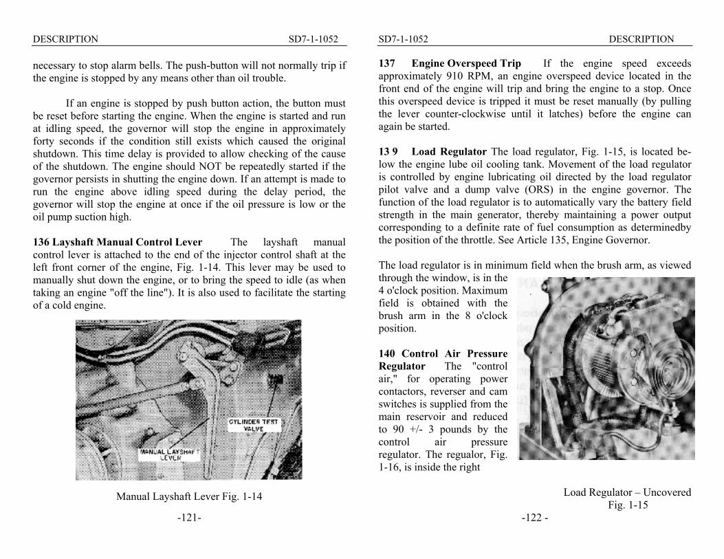
If an engine is stopped by push button action, the button must be reset before starting the engine. When the engine is started and run at idling speed, the governor will stop the engine in approximately forty seconds if the condition still exists which caused the original shutdown. This time delay is provided to allow checking of the cause of the shutdown. The engine should NOT be repeatedly started if the governor persists in shutting the engine down. If an attempt is made to run the engine above idling speed during the delay period, the governor will stop the engine at once if the oil pressure is low or the oil pump suction high. 136 Layshaft Manual Control Lever The layshaft manual control lever is attached to the end of the injector control shaft at the left front corner of the engine, Fig. 1-14. This lever may be used to manually shut down the engine, or to bring the speed to idle (as when taking an engine "off the line"). It is also used to facilitate the starting of a cold engine.
Manual Layshaft Lever Fig. 1-14
-121-
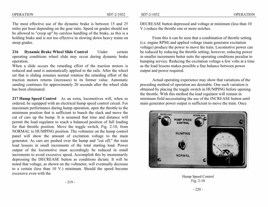
SD7-1-1052 DESCRIPTION 137 Engine Overspeed Trip If the engine speed exceeds approximately 910 RPM, an engine overspeed device located in the front end of the engine will trip and bring the engine to a stop. Once this overspeed device is tripped it must be reset manually (by pulling the lever counter-clockwise until it latches) before the engine can again be started. 13 9 Load Regulator The load regulator, Fig. 1-15, is located be-low the engine lube oil cooling tank. Movement of the load regulator is controlled by engine lubricating oil directed by the load regulator pilot valve and a dump valve (ORS) in the engine governor. The function of the load regulator is to automatically vary the battery field strength in the main generator, thereby maintaining a power output corresponding to a definite rate of fuel consumption as determinedby the position of the throttle. See Article 135, Engine Governor. The load regulator is in minimum field when the brush arm, as viewed through the window, is in the 4 o'clock position. Maximum field is obtained with the brush arm in the 8 o'clock position. 140 Control Air Pressure Regulator The "control air," for operating power contactors, reverser and cam switches is supplied from the main reservoir and reduced to 90 +/- 3 pounds by the control air pressure regulator. The regualor, Fig. 1-16, is inside the right
Load Regulator – Uncovered
Fig. 1-15 -122 -

DESCRIPTION SD7-1-1052 carbody wall adjacent to the electrical cabinet. A bolt and locknut on top of the regulator provides means of adjustment. A control air pressure gauge, with a nameplate "ELECTRIC AIR PRESSURE," is mounted on the rear wall of the cab.
MISCELLANEOUS EQUIPMENT 141 Classification Lights Classification lights are permanently installed in each of the four corners of the carbody. To change the class lights the entire class light box is pivoted outward on a hinge. A rear door provides access to the lamps and markers. The fixed clear bull's eye lens can be made to show red or green by placing a "clipon" type lens of the desired color between the reflector and the clear lens. When not in use, the colored clipon lens are stored to one side of class light box. 142 Number Boxes Translucent number slides may be changed by swinging the class light box outward and reaching down through the opening in the carbody end section. Storage boxes for extra number slides are mounted on the inside of the carbody near the number box. Lamp bulbs are accessible through a hinged door in the top
of the number box. This door is accessible through the opening in the carbody normally occupied by the class light box. 143 Trucks Fully flexible three motor six-wheel trucks are used under the SD7. Full-floating action between the bolster and truck frame is obtained through the use of four sets of vertical double coil springs, one set in each of the four corners of the H-shaped bolster. Lateral movement of the bolster within the truck frame is controlled by
-123-
SD7-1-1052 DESCRIPTION four rubber cushioned bolster stops mounted on the truck frame. Relative movement between the bolster and truck frame is controlled by four spring loaded snubbers. Equalization between axles and additional vertical springing is obtained by placing two sets of triple coil helical springs between each journal box and the truck frame. All axles are equipped with Hyatt roller bearing journal boxes. A stench bomb recess in each journal box is designed to release a pungent odor when the temperature of the box casting around the bomb approximates 220° F. A second recess is provided for applica-tion of a smoke bomb. A new design anti-sluing device and truck lock, requires the removal of but one bolt from the lock on each side and thereby simplifies removal of the truck. Equalization between axles and additional vertical springing is obtained by placing two sets of triple coil helical springs between each journal box and the frame. 144 Hand Brake An outside mounted hand brake is located in a recessed pocket, Fig. 1-17, in the right rear corner of the car-body. The brake, effective on the trailing axle of the rear truck, is applied by "pumping" the long handle up and down. Hand brakes are released by pulling up on the short release lever. Before moving the locomotive be sure the brakes arecompletely released.
Hand Brake Applied Fig. 1-17
-124 -

DESCRIPTION SD7-1-1052
- 125 -
SD7-2-1052 OPERATION
SECTION 2
OPERATION
The successful and dependable operation of the locomotive is dependent upon the quality of inspection and repair at regular maintenance periods,' as well as the proficiency of the operating crews. As a supplement to the regular terminal maintenance, a "pre-service check" should be made by the engine crew upon boarding the locomotive. 200 When Boarding The Locomotive A. Inspect locomotive exterior and running gear for:
1. Liquids leaking from the locomotive.
Gen
er A
rran
gem
ent
al Fig.
1-1
6
2. Loose or dragging parts. 3. Position of angle cocks and shut-off valves. 4. Brake cylinder piston travel, if air brakes are set. 5. Worn or missing brake shoes. 6. Hoses not being used properly positioned or secured.
B. In the operating cab:
1. See that the throttle is in Idle. 2. Center and remove the reverse lever. 3. Check the position of the rotair valve and brake pipe cutout cock.
The handle of the brake pipe cutout cock, also known as the double heading cock, should be horizontal to open the cock and vertical for closed position.
NOTE: These instructions cover locomotives equipped with 24RL brakes.
6BL brakes are comparable to 6ET brakes with which railroads are familiar, therefore detailed instructions on 6BL are not included. See Art. 219.
-200-

OPERATION SD7-2-1052
4. All fusetrons must be securely in place. 5. All knife switches in the electrical cabinet must be closed. 6. The auxiliary generator, alternator field and fuel pump switches on the
engine control panel and the control, fuel pump and generator field switches on the engineman's control stand must be in the ON position.
If the locomotive is to run light or haul a short freight train, the rotair valves in the operating and non-operating cabs should be placed in the PASS and PASS LAP positions, respectively.
AIR BRAKE EQUIPMENT
DSE-24H Brake Valve Fig. 2-1
- 201 -
SD7-2-1052 OPERATION
K-2-A Rotair Valve Fig. 2-3
-202-

OPERATION SD7-2-1052
With long freight trains place rotair valves in FRGT LAP on trailing units, and in FRGT on the operating unit. This will effect a CON-TROLLED EMERGENCY action on each unit.
The CONTROLLED EMERGENCY action CAN BE NULLIFIED (on the operating unit only) if a quick acting emergency is desired, by simultaneously placing the independent and automatic brake valves in the full application and emergency positions, respectively.
7. If the locomotive has dynamic brakes, set the unit selector switch to
correspond with the number of units in the consist (1, 2, 3 or 4). 8. Place independent brake valve in full application.
C. With the engine running, the following checks should be made (if
engines are stopped, see Art. 201 and 202 for starting instructions):
1. Check for oil, water and fuel leaks. 2. Check gauges, indicators and switches. 3. Drain condensation from air brake system. 4. In the cabs of trailing units, set the rotair valve in the proper "LAP"
position and see that the brake valve is properly cut out.
5. Release hand brake on each unit.
6. Check all battery ammeters to see that the auxiliary generator in each unit is "charging. " The ammeters, Fig. 2-4, should read zero or show a slight charge.
7. Place isolation switch in the RUN position.
Battery Ammeter
Fig. 2-4
- 203 -
SD7-2-1052 OPERATION 201 Precautions Before Starting Engine The following operations should be performed when an engine is to be started after a layover. If the engine has been stopped for a short period of time, or if less than the time limit set by the mechanical officials of the individual railroad, Item 9 may be omitted.
1. Place the independent brake in full application. 2. Remove the reverse lever from the controller. 3. Check position of all valves, drains in cooling system, lube oil
system, and air reservoirs. 4. Check engine cooling water level. 5. Check lube oil supply:
a. In engine crankcase b. In engine governor c. In air compressor
6. Close all switches in the electrical cabinet and check to see that all fusetrons are in place.
7. At engineman's control station move the control switch to ON.
8. Check PCS light. 9. Test for water accumulation
in engine cylinders. a. Open all cylinder test
valves 3 full turns. b. Pull engine manual
layshaft to closed position (unti1 it stops).
c. If the engine has been shut downfor a considerable period of time, omit Steps b and d, remove 400 ampere starting fuse and jack engine over by hand
Pre-Start Engine Test Fig. 2-5
-204-

OPERATION SD7-2-1052
Location Of Gauges, Relays And Equipment Fig. 2-6
- 205 -
SD7-2-1052 OPERATION
CHECK CHART
Item Reading Or Condition REF ART No
STEAM TRAINLINE Per R.R. Instructions2. STEAM GENERATOR Per R.R. Instructions3. STARTING CONTACTORS Must Not Stick Closed 5124. ISOLATION SWITCH "RUN" 2035 BATTERY CHARGING 0 or + 0 or + 2006. CONTROL AIR PRESSURE 90 +/- 3 5187. GROUND RELAY Pointer To Yellow Dot 5018. BOILER WATER LEVEL As Required -9. UNIT SELECTOR SWITCH Same As No. Of Units 11810. HEADLIGHT CONTROL Position As Re aired 117
11, LUBE OIL LEVEL Between Low And Full 40312. FUEL FLOW Thru Glass Nearest Engine 51613. OVERSPEED TRIP Latched (Pull To Reset) 51314. THROTTLE POSITION Same As Control Stand 51715. GOVERNOR OIL LEVEL Between Lines While 16. WATER LEVEL Between Running Levels 40217. WATER TEMPERATURE 121 F. Min. 165° F. - 15° P40018. LUKE OIL PRESSURE Between Lines While 40519. LOAD REGULATOR Same As Other Units 30;
MAIN RESERVOIR 130# To 140# 41021. AIR COMPRESSOR 45# When Pumping
PRESSURE22. AIR COMPRESSOR OIL 16# Min. - Hot Oil23. AIR COMPRESSOR OIL FULL-Do Not Check While 24. AC CONTACTOR Check Reset Buttons

OPERATION SD7-2-1052
d. With isolation switch in START position, press engine start button IN for sufficient time to rotate engine a few revolutions.
e. Check cylinder test valves while engine is being rotated. If discharge of water appears do not attempt to start engine until water accumulation cause has been corrected.
f. Close test valves. g. Replace starting fuse if Step c was followed.
202 To Start Engine
1. Turn on fuel pump switches at engineman's control stand and at engine control panel. Check for fuel flow through sight glass on fuel filter nearest engine, Fig. 2-7.
2. Check setting of overspeed trip. 3. Check engine low oil pressure trip button. 4. Push in layshaft part
way. 5. Press in engine start button until engine completely starts (not more
than 15 seconds). The isolation switch must be in the START position before the start button is effective.
Engine Check Points Fig. 2-7
- 207 -
SD7-2-1052 OPERATION
6. Check oil pressure. 7. Check starting contactor interlocks. 8. Check ground relay. 9. Idle engine until water temperature is approximately 120° before
working engine under load. 10. For trouble shooting of starting difficulties see Section 5.
203 Placing an Engine On The Line
1. After the oil pressure has built up, the engine is placed "on the line " by merely placing the isolation switch in the RUN position (whether the locomotive is standing still or under power).
2. If an engine has been taken off the line for any reason, DO NOT place it on the line if the locomotive is being operated in dynamic braking.
204 To Stop Engine There are three ways of stopping the engine and can be designated as (1) normal (2) under power, and (3) emergency.
1. Normally stopping an engine applies when the locomotive is standing still. In this case place the isolation switch in the START position and press in on the STOP button on the engine control panel until the engine stops.
2. To take an engine off the line (when the locomotive is under power or in dynamic braking) pull the engine layshaft closed until the engine stops. Place the isolation switch in the START position and the fuel pump switch on the engine control panel in the OFF position.
3. All engines of the locomotive are stopped in an emergency by depressing the STOP button on the end of the throttle lever and pushing the throttle lever as far forward as possible.
- 208 -

OPERATION SD7-2-1052 205 Securing Locomotive For Layover
1. Place selector lever in the OFF position. 2. Place reverse lever in neutral and remove it from the controller. 3. Move all switches in engineman's control stand and engine control
panel to OFF and open all switches in the electrical cabinet except the ground switch (after stopping engines).
4. For freezing weather precautions see Art. 225. 206 Precautions Before Moving Locomotive
1. NEVER move a locomotive, under its own power, without having first observed proper application and release of the brake shoes.
2. Check the main reservoir and the control air pressure. 3. Release hand brakes. 4. Engine cooling water should be 120° or more.
207 Handling Light Locomotives With the engines placed on the line and cab preparations completed the locomotive is handled as follows:
1. Move generator field switch to ON. 2. Insert and move the reverse lever to the desired position. (This lever
is to be moved ONLY when the locomotive is standing still.) 3. Place the selector lever in the RUN position. 4. Depress safety control foot pedal (if used). 5. Release the air brakes. 6. When running light, open the throttle a notch at a time. When
kicking cars etc., the throttle may be advanced as far and as rapidly as needed. USE CAUTION. Escapement mechanism in the control stand is not used on the
- 209 -
SD7-2-1052 OPERATION SD7; therefore, throttle movement is not mechanically restricted to one notch at a time. 7. The throttle must be in IDLE before coming to a dead stop. 208 Pumping Up Air After the coupling has been made and tested and the air hose connections have been made, the time required to pump up the train may be reduced as follows:
1. Move the generator field switch on the engineman's control stand to OFF.
2. Place reverse lever in neutral. 3. Open throttle to 4th, 5th, or 6th notch as needed.
209 Starting A Train Starting a train depends not only on the kind of locomotive being used, but also on the type, length, weight, grade, weather conditions and the amount of slack in the train. Because of the locomotive's veryHIGH STARTING TRACTIVE EFFORT it is important that the air brakes be COMPLETELY released before attempting to start the train. Actual tests have shown that a 100 car train, having the average uniformly distributed leakage, may require 9 minutes to completely release the brakes. It requires approximately 30 minutes (with 130 pound main reservoir pressure) to completely charge a depleted air system on a similar 100 car train.
The load indicating meter, Fig.2-8, can be used as a PULL METER to judge the tractive effort of the locomotive. Merely looking at the ground and listening to the engine exhaust may give a false indication of the locomotive's draw bar pull.
The SD7 locomotive is designed to have a COMPARATIVELY RAPID YET SMOOTH BUILD UP OF POWER. Load regulator timing is quite fast in moving from minimum to maximum and somewhat slower from
-210-

OPERATION SD7-2-1052 maximum to minimum. This is due to a special design pilot valve bushing in the governor.
With this arrangement a power build-up equal to the throttle position is very quickly obtained. Any further advancement of the throttle is accompanied by an almost immediate additional increase in power. This may be seen by observing the speed with which the load indicating meter responds to throttle advance.
With a power control of this type the rate and extent of power build-up is left largely to the desire of the engineman yet is still controlled by the load regulator and engine governor.
When ready to start, the following general procedure is recommended:
1. Place the selector lever in the RUN positionand move the reverse lever to the desired direction.
2. Place foot on the safety control foot pedal (DEADMAN) and release
the brakes.
Load Indicating Meter
Fig. 2-8
- 211 -
SD7-2-1052 OPERATION
3. Open the throttle one notch every 1 to 2 seconds as follows:
a. To Run 1 - note the load meter pointer start moving to the right. b. To Run 2 - note engine speed increase. At an easy starting place,
the locomotive may start the train in Run 1 or 2. c. To Run 3 or higher (experience and the demands of the schedule
will determine this) until the locomotive moves.
4. Reduce throttle one or more notches if acceleration is too rapid. 5. After the train is stretched, advance throttle as desired.
NOTE: If the wheel slip indicator flashes repeatedly, reduce the throttle
one notch. Apply sand as needed to prevent further slipping and reopen the throttle when rail conditions improve. "See Art. 210 -Automatic Sanding In Power.
Although it will generally be unnecessary to take slack An starting, there
will be cases where it is wise to do so, after making sure that all brakes are released. The throttle should be opened one notch at a time, in starting a train. A TONNAGE TRAIN SHOULD BE STARTED IN AS LOW A THROTTLE POSITION AS POSSIBLE, BEARING IN MIND THAT THE SPEED OF THE LOCOMOTIVE MUST BE KEPT AT A MINIMUM UNTIL THE TRAIN HAS BEEN STRETCHED. Sometimes it is advisable to reduce the throttle a notch or two the moment the locomotive begins to move, in order to prevent stretching the slack too quickly. The engineman must be the judge of the acceleration and the conditions under which the train is being started.
-212-

OPERATION SD7-2-1052
When the locomotive has moved far enough to completely stretch the train, the throttle may be advanced as quickly as desired, but should not be advanced so quickly that slipping results. Smooth acceleration is obtained by opening the. throttle one notch each time the pointer of the load meter begins moving to the left. 210 Automatic Sanding In Power SD7 locomotives are available with automatic sanding in power to assist in controlling wheel slip. When operating in transition one (1) sanding automatically takes place while slip is in its "creep" or initial stage. In this manner a wheel slip is "anticipated" and prevented before any appreciable loss of tractive effort occurs.
In transition 2, 3, and 4 (and on some occasions in transition 1) automatic sanding, caused by wheel slip, is accompanied by a reduction in main generator output.
Duration of sanding, after the wheel slip or creep has stopped, is controlled by the setting of a time delay sanding (TDS) relay. An off-on circuit breaker switch on the engineman's control panel cuts in or out this sanding-in-power feature.
With the automatic sanding feature "cut-in" (autosanding switch "ON") throttle reduction to avoid repeated wheel slip will rarely be necessary. Also, manual operation of the sanders by the engineman at points onthe road where slippage is likelyto occur can be eliminated. 211 Accelaration Of A Train After the throttle is in the 8th notch and the train begins to accelerate, the indicating meter pointer will move slowly to the left. Forward and backward transition will automatically take place without any attention on the part of the engineman, other than necessary throttle reductions to keep under any speed restriction.
- 213 -
SD7-2-1052 OPERATION 212 Slowing Down Because Of A Grade
1. As the train slows down on a grade the pointer on the indicating meter will move slowly toward the right. Backward transition will take place automatically.
213 Operating In Short Time Overload Zone On SD7 locomotives equippedwith 65:12 or 62:15 gearing, the traction motor is self-protecting, in most applications, with operation being limited only by available adhesion. '
A plate mounted below the meter dial, Fig. 2-8, shows the permissible time of operation at different stages of overload. The short time overload ratings are accumulative, which means that it is permissible to operate the full time of each rating consecutively or in any combination.
When starting a train, the pointer of the load indicating meter may go beyond the continuous rating (900 amperes). This is of no concern provided the pointer soon moves to the left of the continuous rating. However, if the pointer remains in the overload area or enters it on a grade, the rules governing the use of the short time ratings given in the preceding paragraphs will apply.
This data serves as a general guide to locomotive use. To obtain a maximum tonnage rating for any single application, Electro-Motive will, upon request, analyze the actual operation and make specific tonnage rating recommendations.
BRAKING 214 Air Braking With Power The method of handling the air brake equipment is left to the dis cretion of the individual railroad. However,
- 214 -

OPERATION SD7-2-1052
SD7-2-1052 when braking with power it musposition the draw bar pull rapidlpull might become great enoughas the train speed drops. Since thamperage on the load meter, thethe train during a slow down, bymeter. This is accomplished byamperage starts to increase. It isbe kept fully released during powbefore the locomotive comes to 215 Dynamic Brake Operationadditional electrical equipment pby the momentum of the train topower, retarding the speed of thedynamic brake and is especially grades.
The traction motor armawhenever the train is moving. Wcircuits are set up which change takes power to rotate a generatorgenerated is dissipated in resistodriven fan. The grids and fans ar
Before using the dynamthe unit selector switch, located correspond with the number of uthis, place the throttle in Idle, anselector lever to the "B" position
OPERATION
t be remembered that for any given throttle y increases as the train speed decreases. This to part the train unless the throttle is reduced e pull of the locomotive is indicated by the
engineman can maintain a constant pull on keeping a steady amperage on the load reducing the throttle a notch whenever the recommended that the independent brakes
er braking. The throttle MUST be in Idle a stop.
Some locomotives are provided with ermitting a portion of the power developed be converted into an effective negative train. This feature is known as the useful as a holding brake on descending
tures, being geared to the axles, rotate hen using the dynamic brake, electrical the traction motors into generators. Since it this action retards the train. The power thus rs, called grids, which are cooled by a motor e located in the top of the carbody.
ic brake a check should be made to see that on the engine control panel, is set to nits in the locomotive consist. Following d wait about 10 seconds before moving the . In the “B” postion the dynamic braking
- 216 -

OPERATION SD7-2-1052 circuits are partially established and depending upon the speed of the train, enough braking may be present in this position to bunch the slack. If necessary, move the lever beyond "B" and wait until the slack is bunched, After the slack is bunched the lever may be moved farther to the right to give desired amount of braking effort. The dynamic brake is, in effect, very similar to an independent brake and the load indicating meter serves the purpose of a "brake cylinder pressure gauge."
When the dynamic brake circuit is equipped with a current limiting regulator, the braking amperage is automatically limited to a maximum of 700 amperes regardless of locomotive speed or selector handle position.
Placing the selector handle in "B" position will result in an amount of grid current dependent upon locomotive speed and generator residual voltage. At maximum speed, if the throttle has been in idle at least ten seconds before moving the selector handle to "B" position, this slight residual voltage will result in about 200 amperes at the grids.
NOTE: As the BKT power-braking transfer switch does not move when the selector handle is moved from "RUN" to "OFF, " generator residual current will not affect the dynamic braking circuit when the selector handle is in "OFF" position.
Movement of the selector handle from "B minimum" toward
"B maximum" will result in increased braking (grid) current. Also, as soon as the lever leaves the "B minimum" position engine speed will increase to 500 RPM to insure that 700 ampere braking current is possible and to provide additional cooling for the traction motors. When the handle has been advanced beyond the position required for 700 ampere braking, the regulator will operate to give the main generator shunt field the proper amount
- 217 -
SD7-2-1052 OPERATION of "buck" excitation, resulting in a net generator excitation value for 700 ampere braking.
If maximum dynamic braking is desired, the selector handle may be advanced slowly to the right toward "B maximum" position. Once 700 amperes has been reached, further movement of the selector handle will result in a braking current exceeding 700 amperes as long as the handle is being advanced, but will reduce to a nominal 700 amperes a few seconds after the handle is stopped. As this momentary overcurrent (indicated by the load ammeter and possibly brake warning light flashing) is not harmful, no attempt should be made to reduce braking current manually by moving the handle back and then advancing it again. Such an effort to put out the light would probably result in the regulator hunting. Instead, it is suggested that the selector handle movement be stopped until the light goes out. The light MUST GO OUT WITHIN 15 SECONDS after the handle movement has been stopped. If handle movement is stopped when 700 ampere braking is reached andthe train speed increases, braking current will not exceed a nominal 700 amperes.
The range (and purpose) of the regulating system is such that it is impossible to exceed a nominal 700 ampere braking current, except momentarily, regardless of locomotive speed or selector handle position.
When necessary, the automatic brake may be used in conjunction with the dynamic brake. However, the independent brake must be KEPT FULLY RELEASED whenever the dynamic brake is in use, or the wheels may slide. As the speed decreases below 10 miles per hour the dynamic brake becomes less effective. When the speed further decreases, tt is permissible to completely release the dynamic brake by placing the selector lever in the "OFF" or "RUN" position, applying the independent brake simultaneously to prevent the slack from running out.
- 218 -
OPERATION SD7-2-1052 The most effective use of the dynamic brake is between 15 and 25 miles per hour depending on the gear ratio. Speed on grades should not be allowed to "creep up" by careless handling of the brake, as this is a holding brake and is not too effective in slowing down heavy trains on steep grades. 216 Dynamic Brake Wheel Slide Control Under certain operating conditions wheel slide may occur during dynamic brake operation. When a slide occurs the retarding effort of the traction motors is reduced and sand is automatically applied to the rails. After the wheel set that is sliding resumes normal rotation the retarding effort of the traction motors returns (increases) to its former value. Automatic sanding continues for approximately 20 seconds after the wheel slide has been eliminated. 217 Hump Speed Control As an extra, locomotives will, when so ordered, be equipped with an electrical hump speed control circuit. For maximum performance during hump operation, open the throttle to the minimum position that is sufficient to bunch the slack and move the cut of cars up the hump. It is assumed that time and distance will permit the load regulator to reach a balanced position of full loading for that throttle position. Move the toggle switch, Fig. 2-10, from NORMAL to HUMPING position. The voltmeter on the hump control panel will show the amount of excitation voltage to the main generator. As cars are pushed over the hump and "cut off," the train load lessens in small increments of the total starting load. Power output of the locomotive must accordingly be reduced in small increments to avoid excessive speed. Accomplish this by momentarily depressing the DECREASE button as conditions dictate. It will be noted that voltage, as shown on the voltmeter, will eventually decrease to a certain (less than 10 V.) minimum. Should the speed become excessive even with the
- 219 -
SD7-2-1052 OPERATION DECREASE button depressed and voltage at minimum (less than 10 V.) reduce the throttle one or more notches.
From this it can be seen that a combination of throttle setting (i.e. engine RPM) and applied voltage (main generator excitation voltage) produce the power to move the train. Locomotive power can be reduced by reducing the throttle setting; however, reducing power in smaller increments better suits the operating conditions peculiar to humping service. Reducing the excitation voltage a few volts at a time as the load lessens makes possible a fine balance between power output and power required.
Actual operating experience may show that variations of the preceding method of operation are desirable. One such variation is obtained by placing the toggle switch in HUMPING before opening the throttle. With this method the load regulator will remain in minimum field necessitating the use of the INCREASE button until main generator power output is sufficient to move the train. Once
Hump Speed Control Fig. 2-10
- 220 -
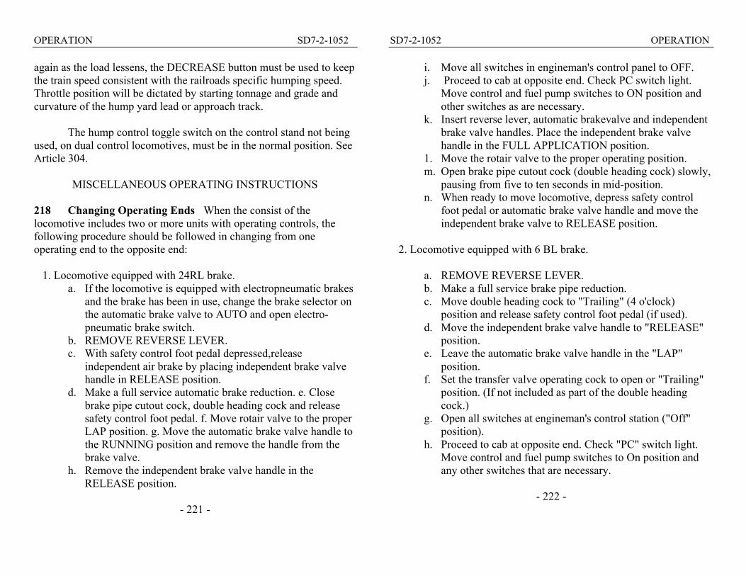
OPERATION SD7-2-1052 again as the load lessens, the DECREASE button must be used to keep the train speed consistent with the railroads specific humping speed. Throttle position will be dictated by starting tonnage and grade and curvature of the hump yard lead or approach track.
The hump control toggle switch on the control stand not being used, on dual control locomotives, must be in the normal position. See Article 304.
MISCELLANEOUS OPERATING INSTRUCTIONS 218 Changing Operating Ends When the consist of the locomotive includes two or more units with operating controls, the following procedure should be followed in changing from one operating end to the opposite end:
1. Locomotive equipped with 24RL brake. a. If the locomotive is equipped with electropneumatic brakes
and the brake has been in use, change the brake selector on the automatic brake valve to AUTO and open electro-pneumatic brake switch.
b. REMOVE REVERSE LEVER. c. With safety control foot pedal depressed,release
independent air brake by placing independent brake valve handle in RELEASE position.
d. Make a full service automatic brake reduction. e. Close brake pipe cutout cock, double heading cock and release safety control foot pedal. f. Move rotair valve to the proper LAP position. g. Move the automatic brake valve handle to the RUNNING position and remove the handle from the brake valve.
h. Remove the independent brake valve handle in the RELEASE position.
- 221 -
SD7-2-1052 OPERATION
i. Move all switches in engineman's control panel to OFF. j. Proceed to cab at opposite end. Check PC switch light.
Move control and fuel pump switches to ON position and other switches as are necessary.
k. Insert reverse lever, automatic brakevalve and independent brake valve handles. Place the independent brake valve handle in the FULL APPLICATION position.
1. Move the rotair valve to the proper operating position. m. Open brake pipe cutout cock (double heading cock) slowly,
pausing from five to ten seconds in mid-position. n. When ready to move locomotive, depress safety control
foot pedal or automatic brake valve handle and move the independent brake valve to RELEASE position.
2. Locomotive equipped with 6 BL brake.
a. REMOVE REVERSE LEVER. b. Make a full service brake pipe reduction. c. Move double heading cock to "Trailing" (4 o'clock)
position and release safety control foot pedal (if used). d. Move the independent brake valve handle to "RELEASE"
position. e. Leave the automatic brake valve handle in the "LAP"
position. f. Set the transfer valve operating cock to open or "Trailing"
position. (If not included as part of the double heading cock.)
g. Open all switches at engineman's control station ("Off" position).
h. Proceed to cab at opposite end. Check "PC" switch light. Move control and fuel pump switches to On position and any other switches that are necessary.
- 222 -

OPERATION SD7-2-1052
i. Insert reverse lever and brake valve handles. Place independent brake valve in "full application" position.
j. Open double heading cock to "Lead" (6 o'clock) position slowly.
k. Place automatic brake in "running" position. 1. When ready to move locomotive, depress safety control foot pedal, and move independent brake valve to "RELEASE" position.
NOTE: When hauling locomotive "dead" place the independent and
automatic brake valve handles in the RELEASE and RUNNING positions, respectively, move the double heading cock to the 3 o'clock position and open the dead engine cock. See Art. 227 in this section.
Locomotives equipped with safety control foot pedal or automatic train control use the N-1-A brake application valve. The brake valve cutout cock (double heading cock) is mounted on this N-1-A brake application valve instead of on the automatic brake valve.
219 Multiple Unit Operation In some instances it may be desirable to operate SD7 units, that have different gear ratios, in multiple with each other. In such cases the following precautions should be observed.
If the units of the consist are of different gear ratios and/or different continuous ratings, the locomotive should not be operated so that the unit geared for the HIGHEST minimum speed is overloaded by being operated below that speed, or short time rating; nor must the locomotive be permitted to operate at speeds in excess of that for the unit having the LOWEST maximum permissible speed. 220 Operating With A Helper Locomotive Basically there is no difference in the instructions. for operating the locomotive with a
- 223 -
SD7-2-1052 OPERATION Steam or Diesel helper as compared to operating the locomotive without a helper.
It is always desirable to reach the top of a grade in the least possible time in order to avoid possible damage to the electrical equipment.
Helper locomotives may have tonnage ratings which are based on lower speeds than those for the principal locomotive. Under these conditions it is permissible to operate the principal locomotive within the limits of the short time ratings. Under these same conditions, when the drag speed of the helper locomotive is lower than that of the principal locomotive (that is, with a Steam helper locomotive or a Diesel helper locomotive of a higher gear ratio), it is permissible to reduce the throttle of the principal locomotive when the 8th throttle operation results in a meter reading that exceeds the maximum short time rating. By this procedure it will be found that maximum advantage can be taken of the combination of the principal and helper locomotives. The throttle must be successively reduced as the higher short time ratings are consumed but should not be operated below the 5th notch. If the time limit for a higher amperage short time rating is not used, that amount of time may be added once, and only once, to any lower amperage time limit. However, if all short time current limitations have been consumed and top of the grade has not yet been reached, tonnage must be reduced.
In case the principal and helper locomotives are identical model Diesels and are of the SAME GEAR RATIO, the principal locomotive will be obliged to operate within its continuous rating to conform with the helper locomotive operation described in Article 221. 221 Operating As A Helper Locomotive The nature of the operation of a helper locomotive is such that its operation is contingent upon the handling and performance of the principal locomotive.
- 224 -

OPERATION SD7-2-1052
Due to the lack of communication between the helper and principal locomotive, there is always the possibility that the helper locomotive, due to unforeseen circumstances in train handling, will be called upon to assume more than its normal share of the load. In view of this possibility, the helper locomotive should be assignedtonnage consistentwith its continuous rating. This will permit the helper locomotive to assume a larger share of the tonnage and still not exceed its short time ratings when the unexpected occasion arises requiring the principal locomotive to reduce throttle.
Instructions included in articles 220 and 221 serve as a general guide to locomotive use. To obtain a maximum tonnage rating for any single application, ElectroMotive will, upon request, analyze the actual operation and make specific tonnage rating recommendations. 222 Doubleheading Prior to doubleheading behind another locomotive, make a full service brake pipe reduction with the automatic brake valve and close the doubleheading cock. Leave the rotair valve in the PASS or FRT position, depending on the type of service and return the automatic brake valve handle to the running position. The operation of the throttle is normal, but the brakes are controlled from the lead locomotive. The engineman on the second locomotive may make an emergency application of the brakes with automatic brake valve, and/or may release his locomotive brakes by depressing the independent brake valve handle. 223 Operation Over Railroad Crossings When crossing railroad crossings, reduce throttle to the 5th notch before reaching crossing and leave reduced until all units are over crossing. This will reduce arcing from the brushes to the motor commutator. 224 Running Through Water Under ABSOLUTELY no circumstances should the locomotive pass through water which is deep enough to touch the bottom of traction motor frames. When passing through water always go at a very low speed (2 to 3 miles per hour).
- 225 -
SD7-2-1052 OPERATION Water any deeper than three inches above the top of the rails is likely to cause damage to the traction motors. 225 Freezing Weather Precautions In freezing weather, precautions must be taken to see that water in the locomotive does not freeze.Protection is generally provided by trainline steam. The steam admission valve, which protects engine cooling, cab heating and hopper water, is located under the left catwalk to the rear of the lead axle of the rear truck. A. If engine and steam generator are inoperative and steam from an
external source is supplied to prevent freezing, the following valves are to be opened:
1. Engine Cooling System.
a. Steam admission valve to engine cooling water and cab
heater supply line "tracer. " b. "G" valve. c. Water admission valve to cab heaters. (Toilet water supply
is heated by engine water from the cab heaters.)
2. Steam Generator.
a. Heating coil valve. b. Water suction line valve. c. Water tank valve. d. For detailed instructions, see Section 6.
B. In freezing weather if heating facilities are not available, all water
must be drained from:
1. Engine cooling system and cab heaters. Remove pipe plug from bottom of right water pump housing. Also, remove pipe plug from cab heater and hopper water tank engine water supply line (accessible through small door in cab floor).
2. Steam generator (see Steam Generator Section).
- 226 -

OPERATION SD7-2-1052
3. Steam Generator Water Tank. 4. Toilet Water Tank. 5. Air System.
a. Air compressor oil separator. b. Sump reservoir. c. Main reservoirs. d. Type H filter. e. Electrical control air regulator. f. Electrical control air reservoir. g. Air compressor intercooler.
226 Splitting And Joining Units
1. Take down all jumpers. 2. Close angle cocks on both units on all air hoses. 3. Break hoses and seperate units by uncoupling. 4. I n joining units:
a. Stretch units to insure couplers are locked. b. Connect hoses and jumpers, and be sure all angle cocks on
all air hoses are opened in both units. c. CUT OUT BRAKES, AND ALL CONTROL SWITCHES
IN ALL BUT THE OPERATING UNIT. Remove reverse lever in trailing cab units.
227 Towing Locomotive 1. Be sure reverse lever is in neutral position. If locomotive is to be towed in a train any appreciable distance, reverser switch, Fig. 2-11, must be placed in neutral and locked in that position. To lock the reverser switch, remove the locking pin which during normal operation is screwed into the left hand side of the reverser housing. With the reverse lever in neutral, punch the buttons on top of reverser switch lightly, to center. After switch has been centered, shut off control air.
- 227 -
SD7-2-1052 OPERATION
Insert pin into hole in the right side of reverser housing, pushing pin all the way through the reverser switch shaft, and screw pin into threaded hole in left side of reverser housing.
2. All isolation switches must be in START position. If it is
necessary to keep the engines idling for any reason while towing locomotive, the fuel pump and control switches should be left in the closed position.
3. The air brake equipment should be set according to the air
brake manufacturer's bulletin. 228 Recovery Of Brake After Penalty Application
1. Place automatic brake valve in LAP. 2. CLOSE THROTTLE TO IDLE. 3. Place foot on safety control foot pedal.
Reverser Switch - Locked In Neutral
Fig. 2-11
- 228 -

OPERATION SD7-2-1052
*4. Wait until application pipe builds up to main reservoir pressure. (Listen for exhaust or watch PCS light).
5. Reset train control. 6. Release brakes.
*If PCS will not reset (i.e. light stays lit) with automatic brake valve handle in LAP, after an emergency application, place brake valve handle in running position.
229 Setting "PC" Switch Recover brake, see Art. 228. If "PC" switch is tripped locomotive will have power in number one throttle position (shown on load indicating meter) but engine speed will not advance as throttle is opened. Fuel pumps will be stopped. In No. 5 or 6 throttle position the engines will stop; no bells will ring. The fuel pump switch in the engineman's control panel in the off or tripped position will cause the same difficulty as a tripped "PC" switch. 230 Ground Relay Pointer points to yellow dot when set, and to a red dot when tripped. When the ground relay is tripped the engine will not speed up when throttle is opened. In No. 5 or 6 throttle position the engine will stop and the purple light will light. To reset, isolate engine, reset relay, and put engine on line. If relay continues to trip isolate unit, Art. 204-232. 231 Wheel Slip Control If slipping occurs, the wheel slip control devices will temporarily take over control of the units main generator power output. The reduced power output of the main generator reduces traction motor torque and stops the slipping. Slipping will be indicated by the wheel slip light. See Art.305, Wheel Slip Control.
-229 -
SD7-2-1052 OPERATION
It will generally be unnecessary to reduce the throttle because of momentary wheel slip action, as the locomotive will automatically reduce its power to stop the slipping and reapply the power after the slipping has stopped.
Under extremely poor rail conditions, repeated wheel slipping may occur and sand should be applied to stop this slipping. Whenever possible, slipping should be anticipated and sand applied to prevent it. Refer to Art. 210 Automatic Sanding In Power. 232 Indication Of A Pair Of Wheels Sliding H one pair of wheels should slide when starting a train, the wheel slip light will flash on and off intermittently. As the train speed increases, the light will stay on more or less continuously and will not go out when the throttle is reduced. The light will go out when throttle is closed to idle.
If this happens, the engine crew should make an immediate investigation to determine the cause. The wheels may be sliding due to a locked brake, a broken gear tooth wedged between the pinion and ring gear, etc.
Repeated ground relay action, accompanied with unusual noises such as continuous thumping or squealing, may also be an indication of serious traction motor trouble that should be investigated at once.
IF A POWER PLANT MUST BE ISOLATED BECAUSE OF REPEATED WHEEL SLIP OR GROUND RELAY ACTION, DO NOT ALLOW THAT UNIT TO REMAIN IN THE LOCOMOTIVE CONSIST UNLESS IT IS CERTAIN THAT ALL OF ITS WHEELS ROTATE FREELY. - 230 -

NOTES
SD7-3-1052 ELECTRICAL EQUIPMENT
SECTION 3
ELECTRICAL EQUIPMENT 300 General Electrical Scheme In full throttle,the rated horsepower of the engine is delivered to the direct coupled main generator. At the main generator the power of the engine is transformed into electrical power. The electrical power is then con-ductedto the six traction motors, three motors being locatedin each truck (eachmotor being gearedto an axle).
The locomotive is designed so that within the current and voltage limits of the main generator, the power (KW) delivered to the traction motors at full throttle is the same, regardless of the locomotive's speed.
The electrical system of the locomotive can be thought of as being divided into three separate systems:
1. High voltage system (includes dynamic braking system - if used).
2. Low voltage system. 3. Alternating current system.
The high voltage system is directly concerned with moving the
locomotive; or in retarding the locomotive in case dynamic brakes are supplied and are in use. The main components of the high voltage system are the main generator, traction motors, transition relays, shunt field contactor, motor shunting contactors, reverser drum, wheel slip relays, ground relay and power contactors. On locomotives equipped with dynamic brakes, the brake transfer switches (cam-switch), brake grids, and brake grid blower motors may also be considered as part of the high voltage system.
The low voltage system contains the circuits which control the flow of power in the high voltage system, and those auxilary circuits
- 300 -

ELECTRICAL EQUIPMENT SD7-3-1052 conducting power to the locomotive lights, heater fans, fuel pump and the main generator battery field. A 64 volt battery, in the low voltage system, is the source from which power is taken to start the diesel engine. Once the engine is started, the auxiliary generator takes over the job of supplying power to the low voltage system.
The alternating current system includes a D-14 alternating current generator (called an alternator), four engine cooling fan motors, and one traction motor blower motor. The alternating current system provides a means of driving accessories, without the use of belt drives, at speeds which vary according to the speed of the engine. 301 Main Generator The main generator (D12C) voltage is nominally 600 volts but this varies with engine speed and the conditions of operation of the locomotive. The main generator contains six field windings: starting, battery, shunt, differential, compensating, and commutating. The starting field is used only when the main generator is used as a starting motor to rotate the engine. With regard to locomotive operation, the shunt and battery fields are the more important; these two fields provide the main excitation of the generator.
The battery field is a low voltage, externally excited field. The current flowing through the battery field, which initially excites the main generator, is varied by the load regulator. Variation of battery field excitation controls the power output of the main generator. The battery field contactor opens or closes the circuit to the battery field.
The main generator is self-excited to the extent of the excitation produced in the shunt field. The shunt field, therefore, is a high voltage field, its excitation varying with the voltage of the main generator. A shunt field contactor opens or closes the circuit to the shunt field.
- 301 -
SD7-3-1052 ELECTRICAL EQUIPMENT Interlocks are built into the shunt field contactor so that this contactor must close before the battery field contactor can close.
The differential, compensating and commutating field are permanently connected and are a matter of engineering design providing desired generator characteristics and proper commutation. 302 Traction Motors The traction motors (Model D27) are direct current, series wound motors geared to the wheel axles. The motors are reversed by changing the direction of current flow in the field windings, the direction of current flow in the armature always being the same. A reverser drum operated by electro-pneumatic control reverses the current flow in the traction motor field windings.
Each traction motor is cooled by forced air conducted to the motors by "floating" bellows type air ducts. These ducts are attached at the center to the bolster and are so designed to maintain a sliding con-tact with the locomotive underframe on the top and the traction motor frame casting on the bottom. Traction motor cooling air passes from the traction motor blowers to the motor cooling ducts via a ventilating duct which is an integral part of the locomotive frame.
The traction motor blower for the rear truck is driven by a 25 HP AC motor. The blower for the front truck is driven by an extension of the auxiliary generator armature shaft. This shaft extension also drives the main generator blower.
The maximum permissible top speed of the locomotive is limited by the safe RPM of the traction motor armature; thus a high speed gear ratio is required for high speed train operation. A low speed gear ratio is needed to start and use full horsepower with low speed tonnage trains without overheating and damaging the electrical equipment.
- 302 -

ELECTRICAL EQUIPMENT SD7-3-1052 303 Automatic Transition SD7 locomotives are basically equipped with four steps of automatic transition. Forward transition 1 to 2, 2 to 3, and 3 to 4 is always made at a predetermined voltage. Backward transition from 4 to 3 and 3 to 2 is also made at a predetermined voltage. Backward transition from 2 to 1 is made at a predetermined amperage.
The term automatic transition is applied to the changing of traction motor connections on a DieselElectric locomotive so that full power may be obtained from the main generator within the range of its current and voltage limits. To look at it another way, transition is a method of adjusting the traction motor "back pressure" (counter-e.m.f. bucking the input of power from the main generator)so that this back pressure will not become too high at higher speeds.
Standing still the traction motors have practically no "back pressure," or resistance to the input of current from the main generator. However, as the locomotive speed increases after starting, in transition 1, Fig. 1-2, the "back pressure" of the traction motors builds up and causes the main generator "pressure" (voltage) to increase so that it can continue forcing current into the motors. Although the main generator can vary its voltage over a wide range, there is a practical operating limit to its ability to increase its voltage. If this practical voltage limit were exceeded the power output of the main generator and corres-pondingly, the engine, would drop off. To prevent this loss of power, a change is made in the electrical circuit just before the drop off begins (the main generator at this time will have reached approximately 940-950 volts).
The first change is from transition 1, Fig. 1-2, (two groups of three motors connected in series, each group paralleled across the generator) to transition 2, Fig. 1-2, (three groups of two motors connected in series, each group paralleled across the generator). This
-303 -
SD7-3-1052 ELECTRICAL EQUIPMENT change in traction motor connection effects a reduction in the "back pressure" of the motors, which in turn allows the voltage in the main generator to reduce itself (with a constant KW generator, as the voltage goes down the amperage goes up, and vice versa). Thus, by shifting to transition 2, more current can pass through the traction motor armatures to maintain the full output of the locomotive.
As the locomotive speed increases there is again a tendency for the power to drop off. This time, when the main generator once again reaches approximately 940-950 volts, another change in the electrical circuit is necessary to again reduce the "back pressure" of the traction motors. When this change, from transition 2 to transition 3 (motor field shunts close), Fig. 1-2, is completed, the main generator continues to operate at full power output until a still higher locomotive speed is reached. At this time, when the voltage returns to 940-950 volts, a second set of motor shunting contactors are closed (once again reducing the traction motor "back pressure") effecting transition from 3 to 4, Fig. 1-2. With decreasing speeds, as caused by grades, a reverse sequence of transition takes place to prevent exceeding the. current limitations of the main generator. 304 Hump Speed Control The hump speed control circuit controls, within its limits, the load regulator "clock" position thereby controlling excitation to the main generator. Operating controls of this circuit are shown in Fig. 3-1. Moving the HUMPING - NORMAL toggle switch to HUMPING position will engergize the hump magnet valve HUMV from the PC wire. See Fig. 3-2.
Hump Speed Control Fig. 3-1
-304-

ELECTRICAL EQUIPMENT SD7-3-1052
When the DECREASE button is pushed in, the HUMV is de-energized, and the ORS is energized which moves the load regulator toward minimum field.
When the INCREASE button is pushed in the HUMV is de-energized, which permits the load regulator to move toward maximum field until it reaches a balanced position of full loading for the throttle position. Continued pushing of the increase button will not overload the engine. Ref. Art. 108 and 217. 305 Wheel Slip Control In general, SD71ocomotives are equipped with three companion arrangements for controlling wheel slip. Relays WCR, WSS, Fig. 3-3, WS14, WS2, WS36, WS5, and WSA are used.
On locomotives furnished with power sanding, the wheel creep relay (WCR) is employed to detect very slow creeping type slips occurring in the low speed, high amperage range of operation. This through cable current type wheel slip relay is set to pick up at 125 amperes differential between the two parallel motor circuits. On locomotives having 62:15 gear ratio, this range would be between zero (0) and eleven (11) miles per hour.
When picked up, the WCR energizes the time delay sanding (TDS) relay which, in turn, energizes the forward (or reverse) sanding magnet valve. The TDS contact remains closed, applying sand to the rails for 20 seconds after the TDS relay coil is de-energized due to WCR dropout.
The function of the WCR is to apply sand to the rails for slip correction soon enough to prevent the slip from progressing to a rate requiring reduction of generator excitation. Where rail adhesion is
-305-
SD7-3-1052 ELECTRICAL EQUIPMENT
Hump Control Circuit Fig. 3-2
- 306 -

ELECTRICAL EQUIPMENT SD7-31452 reduced suddenly enough to permit a creeping wheel to accelerate rapidly, the wheel slip series relay (WSS), and possibly one of the voltage type wheel slip relays, will pick up, causing a wheel slip indication and reduction of generator excitation. To detect slips of a more postive nature than the creep type (occuring in the low speed, high ampere range of operation), a through cable current type wheel slip series relay (WSS) is set to pick up at 150 amperes differential between the two parallel motor circuits. On locomotives having 62:15 gear ratio, this range would be between zero (0) and nine (9) miles per hour. When picked up, the WSS relay energizes the WS train line wire, giving a wheel slip indication light. The battery field contactor drops out, correcting wheel slip by removing generator excitation. The function of the WSS relay is to recognize slow speed wheel slips at or
Relays WCR and WSS Fig. 3-3
- 307 -
SD7-3-1052 ELECTRICAL EQUIPMENT near the continuous rating and effect slip corrections with a minimum loss of tractive effort.
Sensitivity of this wheel slip detection and corrective means are such that it should be unnecessary for the engineman to anticipate slippage by intermittent or continuous sanding. If repeated slipping occurs it would, of course, be necessary to apply sand manually, unless automatic sanding in power, Art. 210, is furnished. Repeated slipping on sand will require throttle reduction.
To detect higher speed slipping, (above nine miles per hour on locomotives having a 62:15 gear ratio) four (4) voltage type wheel slip relays are employed. These relays, indicated earlier in this article, are designated numerically by the motor or motors they protect. Pick-up of a wheel slip relay picks up the wheel slip auxiliary (WSA) relay which, in turn, energizes the WS train line and overriding solenoid (ORS).
To effect slip correction when operating in power, the battery field contactor will open, removing external generator excitation and inserting a resistance to the shunt field to reduce self -excitation.In addition, if automatic sanding in power is furnished, the TDS relay contact energizes the sander magnet valve for twenty (20) seconds, applying sand to the rail to prevent rapid recurring slips.
The four voltage type relays employed indetecting slipping, described in this section, are also employed in wheel slide control (see Art. 306, following). 306 Dynamic Brake Wheel Slide Control Under certain operating conditions wheel slide may occur during dynamic brake operation. Relays used in the control of wheel slip are also used to control this type of wheel slide.
-308-

ELECTRICAL EQUIPMENT SD7-3-1052
When a wheel slip relay picks up, due to a pair of wheels sliding, it in turn causes the WSA relay to pick up, energizing the WS trainline wire and the ORS. Energizing the ORS results in load regulator movement toward minimum field, reducing main generator battery field excitation which, in turn, reduces traction motor field excitation. The retarding effort of the traction motor is thereby reduced, overcoming the slide and permitting the wheel set to rotate normally. The load regulator returns to its former "clock" position and dynamic brake retarding effort increases until it reaches its former value. Rapid recovery of dynamic braking effort is further assisted by automatic sanding of the rails. 307 Reversing Locomotive Movement of the reverse lever to the forward or reverse position energizes the respective FOR or REV magnet valves on the reverser, located in the electrical cabinet. When either of the magnet valves is energized it allows control air to pass through the valve, moving the reverser to the desired direction. With four long segments showing on reverser drum, the reverser is in forward; eight short segments can be seen when in reverse position. 308 Load Regulator The load regulator is an automatically operated rheostat connected in series with the battery field of the main generator. Engine oil pressure is used to force the rheostat to vary its position as directed by a pilot valve in the engine governor, loading the engine according to the throttle setting in the cab.
The load regulator has two components: (1) the pilot valve in the engine governor, and (2)a self-contained unit consisting of an hydraulic vane type motor attached to the commutator type rheostat.
For the purpose of load regulation, the engine horsepower output is determined by the rate of fuel consumption. Thus, for each
-309 -
SD7-3-1052 ELECTRICAL EQUIPMENT position of the throttle (or speed setting on the governor) there is a definite fuel consumption as indicated by the position of the governor power piston, which controls the opening of the injector racks. If the load on the engine should be such that more fuel (consequently, power) is demanded that the predetermined balance point (between load and fuel consumption), the load regulator will automatically reduce the engine load by reducing the battery field strength of the main generator. This reduces the fuel consumption and, correspondingly, power output.
If the engine requires less fuel than the predetermined setting, the load regulator increases the load on the engine by increasing the battery field excitation of the main generator. In this manner, auxiliary generator voltage, temperature changes in the main generator windings, or locomotive speeds do not cause overloading or underloading of the engine and a constant power output is maintained for each throttle setting.
An overriding solenoid, ORS, in the governor, is energized whenever the battery field contactor is open; such as whenever the throttle is in idle, during transition from 1 to 2 or 2 to 1, or during wheel slipaction. The energizing of this solenoid causes the load regulator to move into or toward the minimum field position, depending upon the length of time that the ORS is energized. 309 Battery Field Contactor And Fusetron When the throttle is moved to Run 1 this contactor closes and connects low voltage to the main generator battery field. During transition from 1 to 2 or 2 to 1 the contactor momentarily opens, reducing generator output. A selenium rectifier and discharge resistor are used to dissipate the high voltage induced in the battery field when the BF contactor is opened.
- 310 -
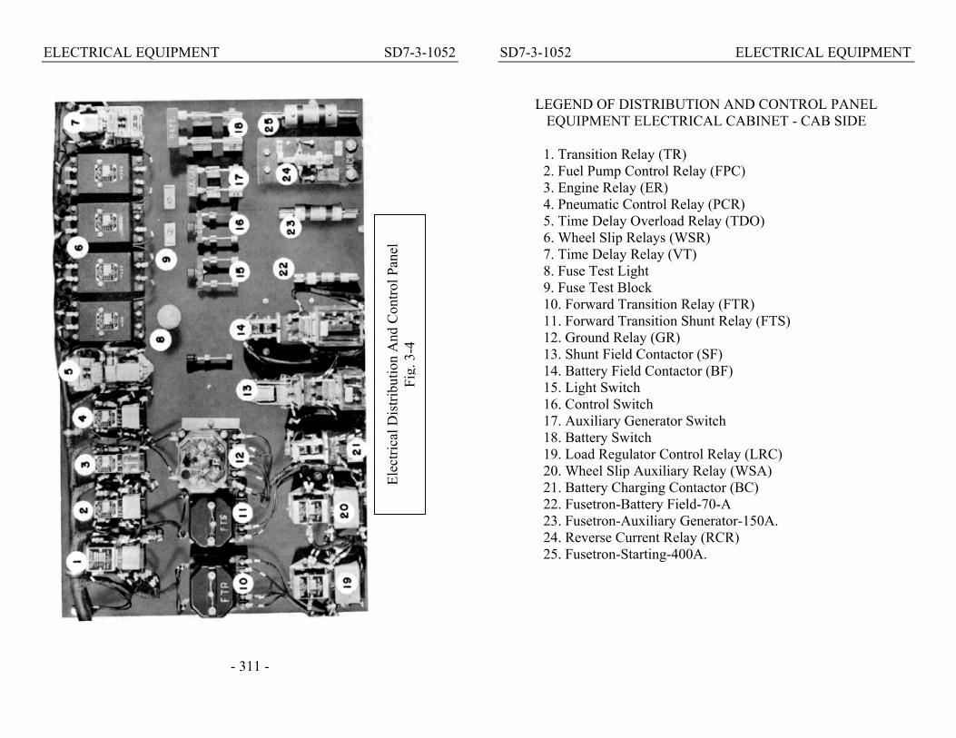
ELECTRICAL EQUIPMENT SD7-3-1052
- 311 -
SD7-3-1052 ELECTRICAL EQUIPMENT
LEGEND OF DISTRIBUTION AND CONTROL PANEL EQUIPMENT ELECTRICAL CABINET - CAB SIDE
1. Transition Relay (TR) 2. Fuel Pump Control Relay (FPC) 3. Engine Relay (ER) 4. Pneumatic Control Relay (PCR) 5. Time Delay Overload Relay (TDO) 6. Wheel Slip Relays (WSR)
Elec
trica
l Dis
tribu
tion
And
Con
trol P
anel
Fi
g. 3
-4
7. Time Delay Relay (VT) 8. Fuse Test Light 9. Fuse Test Block 10. Forward Transition Relay (FTR) 11. Forward Transition Shunt Relay (FTS) 12. Ground Relay (GR) 13. Shunt Field Contactor (SF) 14. Battery Field Contactor (BF) 15. Light Switch 16. Control Switch 17. Auxiliary Generator Switch 18. Battery Switch 19. Load Regulator Control Relay (LRC) 20. Wheel Slip Auxiliary Relay (WSA) 21. Battery Charging Contactor (BC) 22. Fusetron-Battery Field-70-A 23. Fusetron-Auxiliary Generator-150A. 24. Reverse Current Relay (RCR) 25. Fusetron-Starting-400A.

ELECTRICAL EQUIPMENT SD7-3-1052
- 313 -
SD7-3-1052 ELECTRICAL EQUIPMENT A 70 ampere battery field fusetron, located in the low voltage panel protects the battery field circuit. If the fusetron is blown, the unit will not develop normal power. 310 Main Battery Switch This switch is located on the distribution panel and connects the 32 cell, 64 volt, 426 ampere-hour capacity (8 hour rating) battery to the low voltage circuits. An external charging receptacle is located on the side of the locomotive. 311 Battery Ammeter The battery ammeter is located on the engine control panel above the electrical cabinet. This ammeter only shows whether the battery is charging or discharging. Normally the meter will indicate zero or a slight charge. If a continual discharge is shown, the auxiliary generator output should be checked, else the battery may run down. 312 Reverse Current Relay This relay controls the opening and closing of the battery charging contactor (BC). The RCR causes the BC contactor to open when the auxiliary generator voltage drops below the battery voltage. This prevents a reverse flow of current from the battery to the auxiliary generator which in turn prevents motorizing the auxiliary generator. 313 Battery Charging Contactor This contactor is an electrically operated switch connecting the auxiliary generator output to the low voltage system. The reverse current relay controls the operation of the battery charging contactor. 314 Battery Charging Fusetron This fusetron protects the auxiliary generator against any possible overload. A blown battery charging (auxiliary generator output) fusetron will cut off the auxiliary generator from the low voltage system and force the battery to supply the low voltage requirements.
- 314 -

ELECTRICAL EQUIPMENT SD7-3-1052 315 Auxiliary Generator Field Fusetron A 30-ampere fusetron protects the auxiliary generator field windings against excessive current. Blowing of this fusetron will prevent the auxiliary generator from supplying current to the low voltage system. 316 Voltage Regulator A voltage regulator, Fig. 3-6, maintains the auxiliary generator voltage at approximately 74 volts, whenever the engine is running. 317 Ground Relay The ground relay, located in the electrical cabinet, Fig. 3-4, is an electrical protective device connected to the high voltage system. The function of this relay is to automatically unload the main generator in case of a ground in the high voltage system (a ground can be defined as current passing through the frame, or carbody, of the locomotive).
Voltage Regulator
Fig. 3-6
- 315 -
SD7-3-1052 ELECTRICAL EQUIPMENT
If a ground in the high voltage system should occur, the ground relay will trip. When tripped, the ground relay opens the shunt and battery field contactors, unloading the main generator. The ground relay must be reset before the unit can again deliver power. The relay is reset by pressing in on the reset button. Should the relay repeatedly trip when power is applied, the power plant MUST be isolated. CAUTION: Isolate unit before resetting the ground relay.
If the ground relay trips, the white needle in the relay will point to a red dot. In the normal position the needle points to a yellow dot.
With ground relay tripped, the speed of the engine will be reduced to idle and will remain at that speed unless the throttle is in the 5th or 6th notch, in which case the engine will stop.
the ground relay tripping, a low voltage ground can trip the relay when the engine is started; since at that time the high and low voltage systems are temporarily connected. Ground relay action is not necessarily an indication of serious trouble but should be reported to the maintenance authorities.
The ground relay knife switch, when open, eliminates the protection of the ground relay. This switch MUST NOT BE OPENED in normal operation unless definite instructions are issued by an official of the railroad. 318 No AC Voltage Relay As the traction motors in the rear truck are cooled by an AC driven blower, failure of the alternator could result in damage to the traction motors unless the application of power was stopped. Thus, in case of an alternator failure, the NVR
- 316 -

ELECTRICAL EQUIPMENT SD7-3-1052 located in the AC contactor cabinet drops out and causes the alarm bell to ring in all units. It also turns on the purple no power light and reduces the engine speed to idle in the unit affected (if the throttle was in the 5th or 6th notch the engine would stop).
NOTE: An alternator failure indication is usually only the result of an engine being stopped and not the cause of its stopping. The alternator failure alarm will not operate when the isolation switch is in the START position.
SD7-4-1052 SYSTEMS
SECTION 4
COOLING, LUBRICATING OIL, FUEL OIL AND AIR SYSTEMS
COOLING SYSTEM
Water is circulated through the engine radiators and oil cooler
by two pumps mounted on the engine. Cooling air through the radiator is controlled by shutters and four electrically driven cooling fans. The operation of the fans and shutters is entirely automatic and under normal conditions will hold the temperature of the engine cooling water so that the cooling water temperature gauge will read in the green area (120°-190°).
Some units have a Summer-Winter selector switch located in the AC contactor cabinet, Fig. 4-1, to provide a method of altering the sequence of shutter operation. With the switch in the Summer position, the shutters will open when the third fan (#3) is turned on. In the Winter position the shut-ters will open simultaneously with the turning on of the fourth fan (#4).
AC Contactors Fig. 4-1
In the event of excessive cooling water temperature the high temperature alarm switch will close, causing a red light to show in the cab of the unit affected and the alarm bells to ring in all units. 400 Engineroom Winterization The winterization duct consists of a housing and a damper arrangement over the #1 cooling fan to divert, when so set, warm air into the engine room. In the summer
- 400 -
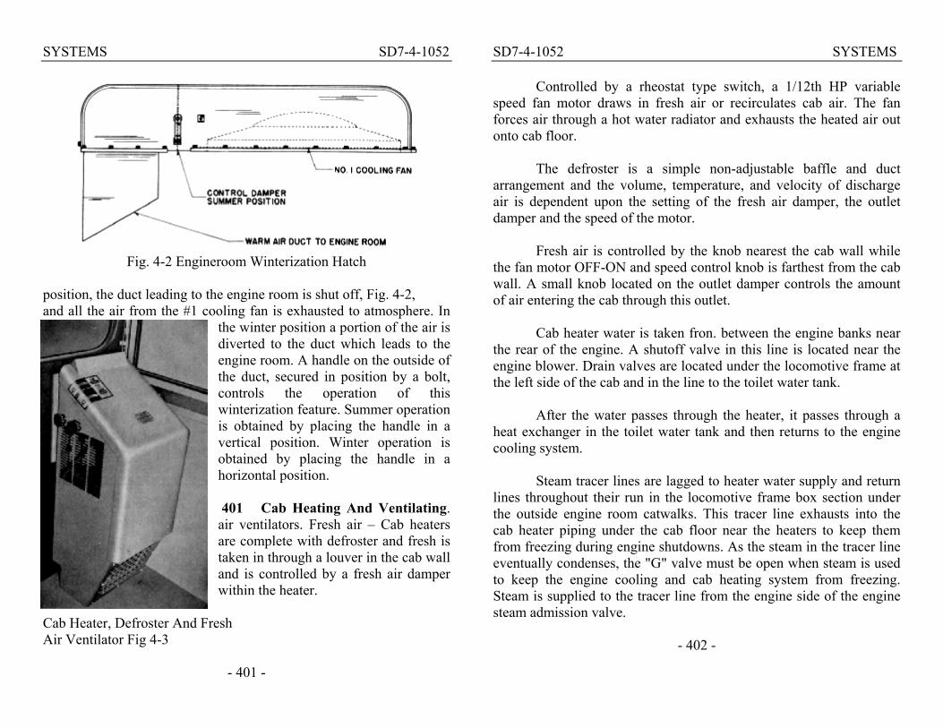
SYSTEMS SD7-4-1052
Fig. 4-2 Engineroom Winterization Hatch
position, the duct leading to the engine room is shut off, Fig. 4-2, and all the air from the #1 cooling fan is exhausted to atmosphere. In
the winter position a portion of the air is diverted to the duct which leads to the engine room. A handle on the outside of the duct, secured in position by a bolt, controls the operation of this winterization feature. Summer operation is obtained by placing the handle in a vertical position. Winter operation is obtained by placing the handle in a horizontal position. 401 Cab Heating And Ventilating. air ventilators. Fresh air – Cab heaters are complete with defroster and fresh is taken in through a louver in the cab wall and is controlled by a fresh air damper within the heater.
Cab Heater, Defroster And Fresh Air Ventilator Fig 4-3
- 401 -
SD7-4-1052 SYSTEMS
Controlled by a rheostat type switch, a 1/12th HP variable speed fan motor draws in fresh air or recirculates cab air. The fan forces air through a hot water radiator and exhausts the heated air out onto cab floor.
The defroster is a simple non-adjustable baffle and duct arrangement and the volume, temperature, and velocity of discharge air is dependent upon the setting of the fresh air damper, the outlet damper and the speed of the motor.
Fresh air is controlled by the knob nearest the cab wall while the fan motor OFF-ON and speed control knob is farthest from the cab wall. A small knob located on the outlet damper controls the amount of air entering the cab through this outlet.
Cab heater water is taken fron. between the engine banks near the rear of the engine. A shutoff valve in this line is located near the engine blower. Drain valves are located under the locomotive frame at the left side of the cab and in the line to the toilet water tank.
After the water passes through the heater, it passes through a
heat exchanger in the toilet water tank and then returns to the engine cooling system.
Steam tracer lines are lagged to heater water supply and return
lines throughout their run in the locomotive frame box section under the outside engine room catwalks. This tracer line exhausts into the cab heater piping under the cab floor near the heaters to keep them from freezing during engine shutdowns. As the steam in the tracer line eventually condenses, the "G" valve must be open when steam is used to keep the engine cooling and cab heating system from freezing. Steam is supplied to the tracer line from the engine side of the engine steam admission valve.
- 402 -

SYSTEMS SD7-4-1052 402 Operating Water Level Operating water levels are stenciled on the water tank next to the water gauge glass to indicate
minimum and maximum water levels with engine running and stopped. The engine should never be operated with the water below the low water level, Fig. 4-4. Progressive lowering of the water- in the gauge glass indicates a leak in the cooling system and should be reported.
The system is filled either through' the filler pipe located on the roof of the locomotive above the water tank, or through the filler pipe on either side just under the catwalk.
Another fill line, capped by a
knurled edge cap, is located near Water Sight Glass the top of the water tank inside Fig. 4-4 the cardbody. This pipe is used
used when adding inhibitor to the cooling water. Idle the engine when adding inhibitor. To fill the system proceed as follows:
1. Stop engine. 2. Open "G" valve. 3. Fill slowly until water runs out the "G" valve drain pipe. 4. Close "G" valve.
If filling a dry or nearly dry engine also follow these additional steps:
-403-
SD7-4-1052 SYSTEMS
5. Start engine and run several minutes. This will eliminate any air pockets in the system. 6. Shut down engine and open "G" valve and wait 3 minutes. 7. Add water until it runs out "G" valve drain pipe. 8. Close "G" valve.
If the cooling system of a hot engine has been drained, do not refill immediately with cold water. If this is done, the sudden change in temperature might crack or warp the cylinder liners and heads. CAUTION: 1. Do not attempt to fill the cooling system through the
drain pipe located underneath the locomotive. 2. The system should not b e filled above the maximum water level indicated o n the water tank to prevent:
a. Freezing of radiators in winter. b. Loss of rust inhibitor when draining back to "G"
valve level.
LUBRICATING OIL SYSTEM Lubricating oil is drawn from the engine oil pan by the scavenging pump and forced through the oil cooling radiator and Michiana filter to the lube oil filler tank strainer chamber. Restriction of the core is reduced to a minimum by agitators in the cooler tubes. Should the oil cooler radiator (which is surrounded by engine cooling water) become restricted, a 60 lb. relief valve, Fig. 4-5, will by-pass the oil around the oil cooler and the Michiana filter. A sight glass in this by-pass line will indicate, by passage of oil, that the oil cooler core is becoming restricted. An access plate permits the removal of the oil radiator from its position inside the oil cooler water tank.
- 404 -
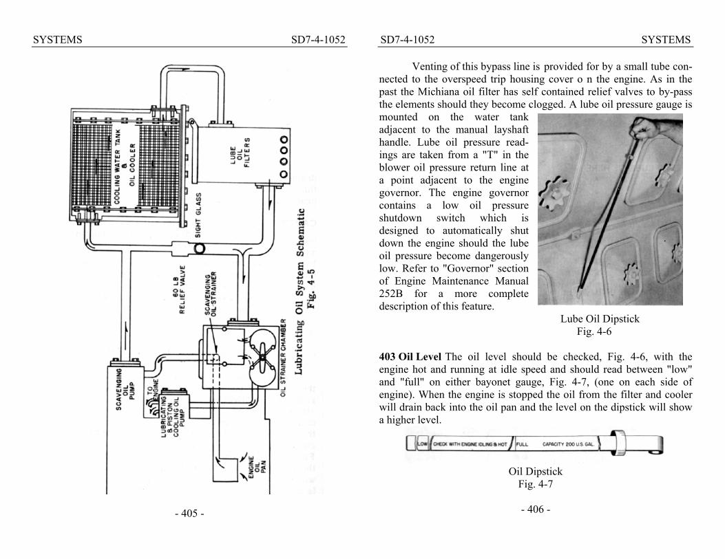
SYSTEMS SD7-4-1052
- 405 -
SD7-4-1052 SYSTEMS
Venting of this bypass line is provided for by a small tube con-nected to the overspeed trip housing cover o n the engine. As in the past the Michiana oil filter has self contained relief valves to by-pass the elements should they become clogged. A lube oil pressure gauge is mounted on the water tank adjacent to the manual layshaft handle. Lube oil pressure read-ings are taken from a "T" in the blower oil pressure return line at a point adjacent to the engine governor. The engine governor contains a low oil pressure shutdown switch which is designed to automatically shut down the engine should the lube oil pressure become dangerously low. Refer to "Governor" section of Engine Maintenance Manual 252B for a more complete description of this feature.
Lube Oil Dipstick Fig. 4-6
403 Oil Level The oil level should be checked, Fig. 4-6, with the engine hot and running at idle speed and should read between "low" and "full" on either bayonet gauge, Fig. 4-7, (one on each side of engine). When the engine is stopped the oil from the filter and cooler will drain back into the oil pan and the level on the dipstick will show a higher level.
Oil Dipstick
Fig. 4-7
- 406 -

SYSTEMS SD7-4-1052 404 Adding Oil To System When oil is added to the system, it must be poured through the opening having the square cap, Fig. 4-8, on top of the housing. Should the round caps be removed while the engine is running, hot oil under pressure will come from the openings and possibly cause personal injury. 405 Oil Pressure Oil pressure at 800 RPM is normally 35 to 45 pounds.
Lube Oil Fill Point Fig. 4-8 It should not drop below 20 pounds. At idle the pressure should be at least 6 pounds (in the event of dangerously low oil pressure the engines will automatically be stopped).
FUEL OIL SYSTEM
Fuel in each unit is circulated through the injectors by an electric fuel pump. Failure of pump to operate, clogged filter, or tripped emergency fuel cutoff valve can cause fuel failure- (Section 5). 406 Fuel Flow For proper engine operation, a good flow of fuel (clear and free of bubbles) should be indicated in the fuel return sight glass, nearest engine, Fig. 4-9.
Return Sight Glass Fig. 4-9
- 407 -
SD7-4-1052 SYSTEMS
Normally, a small amount of fuel will leak by the plunger, and come out the small hole in the stand pipe of the by-pass sight glass. If the leakage is enough so the fuel flows out the top of the standpipe, this fact should be reported to maintenance.
If no fuel is flowing through the fuel return sight glass, check fuel pumps for rotation. If pumps in all units are stopped, check "PC" switch, fuel pump and control switches on the engineman's control panel and the control knife switch inside electrical cabinet.
If pumps in other units are running, check fuel pump circuit breaker switch on engine control panel. If pump is running but no fuel is pumped, check fuel supply, emergency fuel cutoff under the unit, or check for a suction leak in piping between tank and pump, also, check for broken or slipping coupling at fuel pump. 407 Fuel Tanks Basically a 1200 gallon fuel tank is provided. An additional 1200 gallon fuel tank is available, giving a total fuel capacity of 2400 gallons. This extra fuel tank is applicable only where a train heating steam generator is not required as the extra fuel tank occupies the space under the locomotive normally occupied by the steam generator water tank.
Vent lines with flame arrestors are installed on both sides of the tank. Fueling may be performed from either side of the locomotive. A sight glass is located next to each fuel tank filler pipe to indicate when the tank is approaching the full level. In addition, a virtually full length direct view sight glass is installed in the end of the tank to indicate fuel levels below the low level of the sight glasses adjacent to the fill pipes.
Fuel should be filtered through a reliable fuel filter before it enters the tank. DO NOT HANDLE FUEL OIL NEAR AN OPEN FLAME.
- 408 -

SYSTEMS SD7-4-1052
Fuel return from the engine is piped to discharge into the fuel tank near the fuel suction lines. This feature tends to warm the fuel going to the engine and also discourages any contamination from settling near the suction line inlets. Passages between the sump and the tank permit adequate amounts of fuel to pass into the sump and at the same time prevents any fuel surging in the tank from materially agitating the fuel in the sump. Baffles inside the tank parallel to and at right angles with the center line of the locomotive reduce fuel surging to a minimum.
The sump is designed to trap water or other foreign matter, and reduce to a minimum the possibility of premature plugging of the fuel oil filters. Periodically and at times when examination of filters indicate the need, the sump should be drained. 408 Emergency Fuel Cutoff Valve An emergency fuel cutoff valve is located in the sump on the rear of the tank near the bottom left corner. Emergency fuel cutoff rings are located adjacent to each fill pipe and also in the cab. Once the fuel cutoff valve is tripped it must be reset manually.
AIR SYSTEM
Compressor air is not only used on a Diesel locomotive for operating the air brakes and sanders, but is also essential for the proper operation of many other items. The reverser, power contactors, shutter operating cylinders, horn, bell and windshield wipers are also air operated. Schematic drawings of SD7 air compressor control arrangements are shown in Figs. 4-10 and 4-12. 409 Air Compressor Each locomotive power plant is equipped with an air cooled 6-cylinder, twostage air compressor. The compressor is driven through a flexible coupling from the front of the engine crankshaft.
- 409 -
SD7-4-1052 SYSTEMS
- 410 -

SYSTEMS SD7-4-1052
The compressor has its own pump and pressure lubricating system. With the engine stopped the level in the compressor crankcase can be checked on the bayonet type gauge. Lubricating oi1 pressure should be a minimum of 16 pounds at idle speed (275 RPM) with hot oil.
Air Compressor Fig. 4-11
The compressor has four low pressure and two high pressure cylinders. The pistons of all six cylinders are driven by a common crankshaft. The four low pressure cylinders are set at an angle to the two vertical high pressure cylinders. Air from the low pressure cylinders goes to an intercooler, or radiator, to be cooled before entering the high pressure cylinders. The intercooler is provided with a pressure gauge and relief valve. The gauge normally reads approximately 45 pounds when the compressor is loaded. The inter-cooler relief valve is set for 65 pounds. Any marked deviation of intercooler pressure from 45 pounds should be reported at the maintenance terminal.
Condensation and oil collects in the sump of the bottom header of the compressor intercooler and should be drained once at each crew change and at the regular maintenance period. Two drain valves are provided in the sump for this purpose. Operate the intercooler safety valve by hand, when draining the intercooler, to be certain that it functions properly.
Since the air compressor is directly connected to the engine and is in operation at all times when the engine is running, an unloader is provided in the heads of both high and low pressure cylinders which
- 411 -
SD7-4-1052 SYSTEMS cuts out the compressing action when actuated by air pressure. The unloader accomplishes this by blocking open the suction, or intake, valves of the high and low pressure cylinders. When the air operating the unloader is cut off, the unloader releases the suction valves and the compressor resumes pumping. Air pressure from the main air reservoir actuates the unloader valves. 410 Individual Compressor Control Compressor control is basically of pneumatic design and operates as an individual component without regard to main reservoir demands of other units that may be in the consist. Each compressor is equipped with an unloading
Individual Compressor Control Fig. 4-12
- 412 -

SYSTEMS SD7-4-1052 device which is operated by a governor connected to the main reservoir. When main reservoir reaches 140 pounds, the governor actuates the unloader which holds the intake valves open in the compressor, preventing it from pumping air. When the main reservoir pressure falls to 130 pounds, the governor cuts off the air supply to the unloader and the compressor resumes delivery of air. See Fig. 4-12. 411 Synchronized Compressor Control When so ordered, loading and unloading of the compressor in each unit is controlled by an electro-pneumatic system. The electrical arrangement is such that all compressors in the locomotive are synchronized to pump air into their respective main reservoirs when the main reservoir air pressure in any one unit drops to 130 pounds. When the air pressure in all reservoirs reaches 140 pounds, the compressors will unload. Each unit is equipped with a compressor control switch (CCS) actuated by main
Synchronized Compressor Control Fig. 4-13
- 413 -
SD7-4-1052 SYSTEMS reservoir pressure and a compressor relay (CR). A compressor control wire (CC) runs throughout the locomotive and connects the compressor relays in each unit in parallel. See Fig. 4-13.
The compressor control switch is located on the cooling water tank next to the main reservoir air pressure gauge. This switch may be considered to be a single-pole double-throw switch that is thrown to the "loaded" position when the main reservoir pressure drops to 130 pounds, or to the "unloaded" position when the main reservoir pressure reaches 140 pounds. In the unloaded position the CCS causes the compressor control magnet valve to be energized, allowing air to pass through the valve to the compressor unloader pistons. In the loaded position the CCS breaks the circuit to compressor control magnet valve in that unit and causes current to flow through the CC wire ener-gizing the CR relays in each unit. When the CR relay is energized its interlock breaks t h e circuit to the compressor control magnet valve regardless of the position of the CCS in that unit. 412 Manual Air Compressor Control A three-way valve, Fig. 4-12, is provided in case it is desired to keep an air compressor unloaded, irrespective of the compressor control system. Normally the valve handle is in a horizontal position; turning the handle to a vertical position causes the compressor to remain unloaded. Also, see Fig. 4-13. 413 Draining Of Air System The air system should be drained periodically to prevent moisture from being carried into the air brake and electrical control air systems. The frequency of draining will depend on local conditions and can be determined by practice. It is recommended that draining be done at the time of each crew change, until a definite schedule can be determined by the individual railroad.
- 414 -

SYSTEMS SD7-4-1052
FUEL AND WATER CONVERSION TABLE This table lists gallons per inch of fuel or water contained in standard SD7 1200 gallon tanks. Liquid Height - Inches Capacity - Gallons 1 16.5 2 41.6 3 70.9 4 101.7 5 133 6 165 7 197 8 230 9 263 10 297 11 331 12 365 13 400 14 435 15 470 16 506 17 542 18 578 19 614 20 650 21 687 22 723 23 760 24 796 25 833 26 870 27 907 28 944 29 980 30 1017 31 1053 32 1090 33 1127 34 1164 35 1200 36 1235
- 415 -
SD7-5-1052 TROUBLE SHOOTING
SECTION 5
ON-THE-ROAD TROUBLE- SHOOTING
This section is a reprint of the TS6-SD7 edition of the "On-the-
Road Trouble-Shooting" booklet. It provides a check list calling the operator's attention to the troubles which are most frequently encoun-tered on the road, and which can be quickly remedied thereby elim-inating many delays.
No attempt is made to explain general operation and functions of equipment on the locomotive. For such information refer to the other sections of this manual.
- 500 -

TROUBLE SHOOTING SD7-5-1052 500 General The locomotive automatically protects its equipment in case of the faulty operation of most any component. There are two general ways that this protection is obtained: (1) by automatically reducing the engine speed to Idle, or (2) by automatically stopping the engine. An exception is a hot engine alarm which does not change the engine load. In most cases the general location of difficulty is indicated by the alarm bell ringing and the lighting of signal lights in the troubled unit. These lights are: Hot Engine - RED, Boiler Stopped - GREEN, No Power - PURPLE, PC Switch - WHITE, Ground Relay - WHITE. See Figs. 5-1 and 5-2. NOTE: a. All circuit breaker type switches, on the engineman's control
panel, Fig. 5-2, trip open at 15-amperes; except Control and Generator Field, which are 30-ampere circuit breakers. b. The circuit breaker switches are ON (closed) when in the UP position; OFF - DOWN. c. If a circuit breaker is overloaded and trips open, service is restored by first placing switch fully OFF and then moving it to ON.
501 IF Alarm Bells Ring A signal light, Figs.5-1 and 5-2, will be lit in the cab of the unit affected.
Fig. 5-1 Engine Control Panel - Left Side
- 501 -
SD7-5-1052 TROUBLE SHOOTING
Fig. 5-2 - Engineman's Control Panel
RED- Indicates outlet engine water temperature over 208' F. Alarm does not cause a change in engine load or speed. Isolating engine does not extinguish alarm bell or light - alarm signal stops when temperature returns to normal. See that AC cooling fan contactors, Fig. 5-3, are
Fig. 5-3 - AC Contactors
- 502 -

TROUBLE SHOOTING SD7-5-1052 closed (check reset buttons), shutters are open, and water level, Fig. 5-4, is correct. Also, if a summer-winter switch is provided, check position. The control switch circuit breaker in the engineman's control panel, Fig. 5-2, must be ON, or the cooling system fan and the shutter control will b e inoperative. If condition cannot be quickly corrected, isolate engine and investigate (allowing engine to Idle). Position of the engineroom winterization hatch control damper, Fig. 5-5, should be checked.
Fig. 5-4 -Water Sight Glass
GREEN - Indicates steam generator has stopped. To stop alarm light and bell, turn boiler switch OFF, Fig. 5-6. To correct, See Steam Generator Trouble Shooting Chart Sec. 6.
PURPLE _ Indicates a No Power failure; the bell and light are energized by the dropping out of the NVR, Fig. 5-7. This reduces engine
Fig. 5-5 - Engineroom Winterization Hatch
-503 -
SD7-5-1052 TROUBLE SHOOTING PURPLE - speed and load to Run 1, or to STOP if the throttle is in Run 5 or 6. Placing the isolation switch in START, Fig. 5-8, (engine isolated) stops the alarm signals.
Most No Power failure alarms, caused by lack of AC voltage, are "false" since this alarm occurs if the engine stops for any reason while" on the line." With a No Power alarm and the engine stopped,
ALWAYS isolate and start engine before worrying about the" failure." Check overspeed trip and fuel flow, Fig. 5-9, before trying to start an engine that has shut down with no indication other than a No Power failure. If other alarm indications are present with the No Power alarm, they must also be checked before starting the engine.
Fig. 5-6 - Boiler Switch A bona fide alternator (AC)
failure is evident if the purple light and alarm bell are energized while the engine is running with the isolation switch in RUN "on the line!
With a true AC failure, check the auxiliary generator field and alternator field circuit breakers, Fig. 5-10, these must be ON. If circuit breakers are OK, observe battery ammeter - a discharge indication means that auxilary generator fussetron is probably burnt out. Open auxilary generator switch, Fig. 5-11, remove 150 ampere fusetron and check
Fig. 5-7 - NVR Relay
- 504 -

TROUBLE SHOOTING SD7-5-1052 it - insert a good fusetron and close auxiliary generator switch.
Fig. 5-8 - Engine Control Panel - Right Side
Fig. 5-9 - Overspeed Trip And Fuel Flow Check
- 505 -
SD7-5-1052 TROUBLE SHOOTING
If the fuel pump circuit breaker on engineman's control panel is OFF, or if PC switch is open (tripped), the alternator failure alarm will not be able to indicate.
Fig. 5-10 - Engine Control Panel
Fig. 5-11-Distribution Panel The tripping of the governor low oil alarm button, Fig. 5-12, will always stop the engine and will give an alarm if the isolation switch is in Run. Isolate engine and reset low oil trip but ton. Check oil level and condition, Fig. 5-13. If OK, start engine, check the oil pressure, Fig. 5-14, and place engine "on the line. Do not repeatedly start the
- 508 -

TROUBLE SHOOTING SD7-5-1052 engine if governor persists in shutting the engine down. If a low oil alarm should stop the engine while "on the line," a purple No Power light will light since stopping the engine stops the generation of AC voltage. WHITE- When the ground relay light on the engineman's control panel is lit, it indicates a tripped ground relay (indicator pointing to red dot).
Fig. 5-13 - Lube Oil Level This stops the power output in that unit and causes the engine speed to be reduced to Idle, - or to Stop if the throttle is in Run 5 or 6. If the ground relay trips, the indicating light and alarm bell will come on only if the isolation switch is in the Run position.
To correct: isolate engine, reset ground relay, Fig. 5-15, and place engine "on the line. " If ground relay continues to trip, reset to
Fig. 5-14 - Oil Pressure Fig. 5-15 - Ground Relay
- 507 -
SD7-5-1052 TROUBLE SHOOTING stop alarm, and leave engine isolated. Check for a stuck starting contactor(s), Fig. 5-16, if ground relay should trip and refuse to be reset after starting the engine. UNDER NO CONDITION O F REPEATED WHEEL SLIP OR GROUND RELAY ACTION SHOULD A POWER PLANT BE ISO-LATED AND ALLOWED TO REMAIN IN THE CONSIST UNLESS IT IS CERTAIN THAT ALL OF THE WHEELS ARE ROTATING FREELY.
502 Engine Goes To Idle
a. Ground relay might be tripped. b. No voltage relay (NVR) might be open. c. PC switch might be tripped. d. Control circuit breaker on the engineman's control panel might
be "Off." e. Fuel pump circuit breaker on the engineman's control panel
might be "Off."
503 Engine Stops
a. Throttle might be in STOP position. b. Low oil pressure button on the governor might be "out. " c. Engine overspeed device might have tripped. d. No voltage
relay (NVR) might have opened with throttle in RUN 5 or 6.
- 508 -

TROUBLE SHOOTING SD7-5-1052
e. Ground relay might have tripped with the throttle in RUN 5 or 6.
f. Fuel pump circuit breaker on the engineman's control panel
might have been tripped "Off," with the throttle in RUN 5 or 6. g. PC switch might have tripped with the throttle in Run 5 or 6. h. Fuel pump circuit breaker in the engine control panel might be
"Off." i. Control circuit breaker on the control panel might be "Off." j. Emergency fuel cutoff valve under the locomotive might be
tripped, Fig. 5-17.
Fig. 5-17 - Emergency Fuel Cutoff Valve 504 How To Start Engine If the engine has been stopped for a considerable period of time, the cylinders should be tested for fuel or water accumulation before starting engine, see Article 520.
a. Place throttle in Idle and reverse lever in Neutral. b. Place isolation switch in the START position, Fig. 5-8. c. Turn ON, or close, the Auxiliary Generator Field, Alternator
Field and Fuel Pump circuit breakers in the engine control panel.
- 509 -
SD7-5-1052 TROUBLE SHOOTING
d. Close all switches in the electrical cabinet. e. At the engineman's control panel turn ON the Control and Fuel
Pump circuit breakers. f. After allowing a few seconds for fuel to flow through the return sight glass, Fig. 5-18, solidly press the START button and hold until the engine starts. If the engine fails to start after 15 seconds of rotation, check possible troubles listed under Article 506 before again trying to start engine. g. After allowing time for the lube oil pressure to build up, Fig. 5-14, place isolation switch, Fig. 5-19, in the RUN position.
Fig. 5-18 - Sight Glasses
505 The Engine Does Not Rotate When "Start" Button Is Pressed
a. Control circuit breaker on the engineman's control panel must be ON.
b. Isolation switch must be in the START position. c. 400-ampere starting fuse must be good. d. Main battery switch and the control switch in the electrical
cabinet must be closed. 506 The Engine Rotates But Does Not Start When "Start" Button Is Pressed
a. Fuel pump circuit breaker on the engineman's control panel must be ON.
-510-

TROUBLE SHOOTING SD7-5-1052
b. Low oil pressure button on the governor must be pressed "in. " c. Engine overspeed trip must be "set. " d. Fuel pump circuit breaker in the engine control panel must be
ON. e. Emergency fuel cutoff valve, Fig. 5-17, under the locomotive,
must not be tripped. f. The PC switch must not be tripped.
507 The Engine Does Not Speed Up When Throttle Is Opened
a. Control circuitbreaker on the engineman's control panel must be ON.
b. Isolation switch must be in RUN position. c. PC switch must not be tripped.
Fig. 5-19 - Engine Control Panel - Right Side
- 511 -
SD7-5-1052 TROUBLE SHOOTING
d. Ground relay must not be tripped. e. No voltage relay (NVR) must not be open. f. Control switch in electrical cabinet must be closed. g. Fuel pump circuit breaker on engineman's control panel must
be ON. 508 The Engine Speed Picks Up But Locomotive Does Not Move When Throttle Is Opened
a. Reverse lever must be in either reverse or forward position. b. Generator field circuit breaker must be ON. c. There must be 90 pounds (± 3 lbs.) control air pressure. d. Starting contactors must not be stuck. e. Hand, Fig. 5-20, and air brakes must be released. f. 70-ampere battery field fusetron must be good.
509 Battery Ammeter Shows Continual Discharge
a. Battery charging contactor located in the
Fig. 5-20 - Hand Brake Fig. 5-21- Battery Ammeter
- 512 -

TROUBLE SHOOTING SD7-5-1052
electrical cabinet must be closed. b. 150 or 250-ampere battery charging (auxiliary generator)
fusetron must be good. c. The auxiliary generator field circuit breaker in the engine
control panel must be ON. d. The auxiliary generator cutout switch, Fig. 5-22 in the
electrical cabinet must be closed. 510 PC Switch The pneumatic control switch, often called the "power cutoff" switch, is an air operated electric switch that is tripped open by any "penalty" or emergency air brake application. When open, this switch automatically shuts off the fuel pump and reduces the power output of the engine to Run 1 (or to Stop if the throttle is left in Run 5 or 6). A white (PC switch open) indicating light on the engine-man's control panel, Fig. 5-23, will be lit and alarm bell will ring whenever the switch is tripped open.
If the engine stops, the purple No Power alarm light on the engine control panel will come on when the PC switch is reset.
The PC switch is automatically reset provided that: (1) the throttle is returned to Idle, and (2) control of the brake is recovered. To reset:
Fig. 5-22 Fig. 5-23
- 513 -
SD7-5-1052 TROUBLE SHOOTING
a. Close throttle to IDLE. b. Place automatic brake valve in LAP. c. Place foot on safety control foot pedal. d. Wait until application pipe builds up to normal pressure; listen
for exhaust or watch PC switch light. If, after an emergency application, the PC switch does not reset itself with the auto-matic brake in LAP, move the brake valve to RUNNING.
e. Reset train control (if used). f. Place automatic brake valve in RUNNING.
The reason for not completely shutting off the power output of the engine with PC action is to allow the possibility of "plugging" the motors (i.e. electrically reversing them to the direction in which they are moving) in an EXTREME EMERGENCY where the air brakes fail to operate for some cause. However, THE MOTORS MUST NEVER BE "PLUGGED" EXCEPT IN A DIRE EMERGENCY, as this practice can severely damage the electrical equipment. Plugging the motors can be accomplished by closing the throttle to Idle and moving the reverse lever to the opposite direction. For additional braking the
throttle may be opened to Run 1. The controls, to this extent, will operate even though the PC switch may be open. 511 Ground Relay If the ground relay, Fig. 5-24 is tripped, a white indicating light on the engine
Fig. 5-24 - Ground Relay
Fig. 5-25 -514-

TROUBLE SHOOTING SD7-5-1052 man's control panel will light, the alarm bell will ring and the engine will come to Idle (if the throttle is in Run 5 or 6, the engine will stop). To reset relay, place throttle in Idle, isolate engine, and press the reset button. This will move the pointer in the relay from the red dot (tripped) to the yellow dot (set). 512 Starting Contactors The starting contactors, Fig. 5-25, will sometimes weld together when an engine is started, especially if the START button is not held in firmly. If a contactor welds, the unit will not deliver power even though the engine will speed up. The contacts may be separated by prying the contacts apart with a piece of wood or other non-conductive material. When the contacts are open, the interlocks are closed, and vice versa. 513 Engine Overspeed Trip If the engine speed should exceed ap-proximately 910 RPM, an over speed device, Fig.5-26, located on the front end of the engine will trip and stop the engine by preventing the injectors from injecting fuel into the cylinders. The alarm bell and' purple light will come on if the engine is stopped in this manner while
Fig. 5-25 Fig. 5-26 - Overspeed Trip
-515-
SD7-5-1052 TROUBLE SHOOTING "on the line." The overspeed trip must be latched in the SET position before the engine can be restarted. 514 Lube Oil Button On Governor In case of low oil pressure or high suction the governor will stop the engine and cause the alarm bell and purple light to come on. A push-button, Fig. 5-29, on the front of the governor will move out, exposing a red band on the button shaft. To reset, push the button back into the governor housing and start the engine in the usual manner. 515 Emergency Fuel Oil Cutoff Valve Pulling one of the emergency pull cords will trip this valve and stop the fuel supply to the engine. The valve is located in an enclosure at the lower left rear corner of the fuel tank. Reset as shown in Fig. 5-27. 516 Fuel Flow For proper operation, a goodflow of fuel (clear and free of air bubbles) should be indicated by the fuel return sight glass, Fig. 5-28, located on the sintered bronze filter assembly. If fuel is not flowing through return sight glass, check fuel pump motor.
Fig. 5-28 - SightGlasses Fig. 5-27 –
Emergency Fuel Cutoff Valve
- 516 -

TROUBLE SHOOTING SD7-5-1052 If motor is stopped, check. PC switch, circuit breakers and switches on the control panels, also cable connection to motor. If pump is running but fuel i s not pumped, check fuel supply, emergency fuel cutoff valve, a suction leak in piping, suction side of filter or a slipping coupling at fuel pump. 517 Engine Speed Indicator On the governor, Fig. 5-29, the pointer indicates the engine throttle position. It should be the same in all units and correspond with the throttle position in the operating control stand. Fig. 5-29 – PG Governor 518 Control Air pressure For satisfactory operation, the electrical control air pressure gauge on the rear wall of the cab must indicate 90 - 3 lbs. The pressure regulator, Fig. 5-30, is located in the engineroom adjacent to the electrical cabinet. To raise or lower the pressure, change the adjustment on top of the regulator. A drain cock is provided on the bottom of the regulator for draining the moisture. 519 Compressor Control The air compressor is automatically governed and will normally keep the main reservoir pressure at 130-140 p.s.i. In case of trouble, the normal postion of either of the valves
Fig. 5-30
- 517 -
SD7-5-1052 TROUBLE SHOOTING may be changed as shown in Fig. 5-31 to manually load or unload the air compressor.
Fig. 5-31 - Air Compressor Control
520 Cylinder Test Valves Each cylinder is equipped with a test valve, Fig. 5-32, for the purpose of testing for fuel or water accumulation in the cylinders prior to starting an engine that has been,shut down for a considerable period of time.
To make this test, remove the 400-ampere starting fusetron, open all cylinder test valves approximately 3 full turns, and use the engine jacking tool to rotate the engine one complete revolution. If liquid is discharged from any cylinder, investigate; if not, close cylinder test valves, replace 400-ampere starting fusetron, and start engine in the usual manner.
- 518 -

TROUBLE SHOOTING SD7-5-1052 If the engine is running and any cylinder test valve is heard to be leaking, the engine should be stopped, and the valve(s) should be tightened.
Fig. 5-32 - Cylinder Test Valves
521 Tying Up The Locomotive
a. Place isolation switch in START. b. Press STOP button in and hold until engine stops. c. Putall circuitbreakers at the engineman's control panel in the
OFF position. d. Remove reverse lever from controller.
- 519 -
SD7-5-1052 TROUBLE SHOOTING
e. Open main battery switch. f. Set hand brake mounted near the rear platform of the
locomotive. This brake is effective on but one pair of wheels. The brake is applied by pumping the long handle up and down. The brake is released by pulling up on the short release lever. Always release the brake before moving the locomotive.
g. Take all precautions against freezing in cold weather. h. If locomotive is to be left standing outside, cover exhaust
stacks if there is danger of a severe rain.
- 520 -

NOTES
SD7-6-1052 STEAM GENERATOR
SECTION 6
STEAM GENERATOR MODEL OK-4625
INTRODUCTION
The instructions contained in this section are for the guidance
of personnel engaged in the operation of Model OK-4625 steam generators. A general description of the steam generator is given, the operating technique is outlined and a trouble shooting section is provided for the operator.
The symbol number after each device mentioned in the text refers to the schematic operating chart at the end of this section. The numbers are used to facilitate identification of the various devices.
The chart shows the various controls and devices on the OK-4625 steam generator and outlines the flow of fuel, water and steam.
DESCRIPTION
The 4625 steam generators have a rated evaporative capacity of 2750 pounds per hour. Operation is completely automatic after the steam generator is started, and full operating steam pressure is reached within a few minutes.
The steam generating part of the unit includes several sets of coiled water tubing, connected in series to form a single tube several hundred feet long. Feed water, after passing through the heat exchanger, goes through the economizer coil and from there to the main coils of the steam generator. As the water progresses through the coils it is converted into steam. Heat is furnished by the combustion of diesel fuel oil, which is sprayed by compressed air through the atom-
- 600 -

OK-4625 Vapor-Clarkson Steam Generator Fig. 6-1
- 601 -
SD7-6-1052 STEAM GENERATOR izing nozzle in the fuel spray head-105 into the firepot above the coils. Here the fine oil spray mixes with air supplied by the blower-202, and is ignited by a continuous electric spark-220. The hot gases flow, first downward, then up and outward through the coils, finally flowing out the stack,
The supply off fuel is regulated to evaporate 90 to 95% of the water pumped through the coils. The excess water flushes scale and sludge from the coils and is carried over with the steam into the steam separator-221, where the water and sludge are removed before the steam flows into the trainline.
The excess water collects in the bottom of the steam separator. Water above the level off the return outlet flows out through a steam trap-223 and through the heat exchanger-213, where it gives up its heat to the incoming feed water. From the heat exchanger the return water flows through return water flow indicator218 back to the water supply tank-232,
The motor converter-215 drives the blower-202, water pump-230 and fuel pump-209 at a constant speed. The water by-pass regulator-111 automatically controls steam generator output by regulating the amount of water fed to the coils. Before entering the coils, the water passes through servo-fuel control-108, which admits fuel to the spray nozzle in direct proportion to the amount of water entering the coils. The servo-fuel control also adjusts the damper-203 to admit the proper amount of air for efficient combustion of the fuel.
The trainline steam pressure is regulated by adjusting the setting off the water by-pass regulator-111. The length of train and the weather conditions determine the setting.
- 602 -

STEAM GENERATOR SD7-6-1052
BEFORE STARTING
The valves designated by odd numbers must be OPEN during normal operation of the steam generator. Valves designated by even numbers must be CLOSED during normal operation of the steam generator. Normally open valves are fitted with a cross type handle; normally closed valves are fitted with the standard round handle.
1. Make certain that the following valves are OPEN: Atomizing Air Shutoff Valve-1 Coil Shutoff Valve-3 Return Water Outlet Valve-9 Trainline Cross-Over Valve - 11 Steam Admission Valve-13 to Water By-Pass Regulator-11 Three-Way Washout Valve-17 Water By-Pass Regulator Shutoff Valve-19 Water Supply Stop Valve-21 2. Be sure that the following valves are CLOSED: Coil Blowdown Valve-2 Layover Connection Shutoff Valve-6 Manual Water By-Pass Valve-8 Return Line Valve (Standby) -56 Steam Admission Valve-10 to Radiation-217 Washout Inlet Valves-14 and 16 Water Pump Test Valve-18 Water Drain Valves-20 and 22
3. Both overload reset button-106 and stack switch-109 reset
button must be "In. " The overload reset button is located on the magnetic overload relay.
- 603 -
SD7-6-1052 STEAM GENERATOR
TO FILL
1. Open the atomizing air shutoff valve-1 and fill-test valve-4; latch open the separator blowdown valve-12 to drain the steam separator. Close the separator blowdown valve when the separator is completely drained.
2. Close the main switch and turn the control switch102 to FILL. 3. While the coils are filling see that spark-220 is available for
ignition. Check ALL valves. 4. When water discharges from the fill-test valve turn the control
switch-202 to OFF and close the fill-test valve. NOTE: If the coils are empty it will take about five minutes to fill the
steam generator with water.
TO START CAUTION: Do not start the steam generator unless the coils are filled.
1. Latch open the separator blowdown valve-12 and turn the control switch-R02 to RUN. (For easy starting, be sure the control switch has been OFF long enough for the motor to come to a full stop.)
2. Close the separator blowdown valve-22 when the generator
steam pressure gauge-212 registers approximately 200 pounds. 3. OPEN THE SEPARATOR BLOWDOWN VALVE SEV-
ERAL, TIMES FOR THREE TO FIVE SECONDIINTER-VALS DURING TIME FIRST FEW MINUTES OF OPERATION.
- 604 -

STEAM GENERATOR SD7-6-1052 4. Set the water by-pass regulator-111, Fig. 6-4, to the required trainline pressure.
5. After the trainline is coupled, open the remote control trainline shutoff valve-? (if used) by de-pressing the reset lever7a. Then open the
6. trainline stop (shutoff) valve15.
NOTES: 1. Check the return water flow indicator-218, Fig. 6-5, after the steam generator has settled down to a steady output. It should cycle from 4 to 12 times a minute. 2. If the steam generator does not start or function properly, check
all valves to see that they are open or closed as indicated in the operation chart.
3. The steam generator should come up to
full operating pressure in two or three minutes. It may take 10 to 15 minutes to buildup the required operating steam pressure in the trainline, depending upon train length and the condition of the trainline.
- 605 -
SD7-6-1052 STEAM GENERATOR
STANDBY HEATING
Standby heating is applied to SD7 locomotives to prevent freeze-up of the steam generator and its water supply tank at times when the steam generator is not required to make steam. In brief, the generator operates with an amount of fuel sufficient to heat the water but not to make steam, and circulates this hot water through the generator and supply tank.
When the control is switched to "Standby," the unit operates at low fire under control of an aquastat with full circulation of water through the coils, cycling "on" when the water temperature drops to 100° F., and cycling "off" at 145 ° F. During the "off " cycle the warm water is circulated through the system by a small separate pump.
Low fire operation . on "Standby" is obtained through the automatic burner adjusting control and the three-way solenoid valve. The burner control has a spring-loaded, hydraulic piston mechanism which controls the position of the metering pin in the servo. During normal operation, fuel pressure against this piston holds the metering pin up in its operating position.
On "Standby" the solenoid valve relieves the fuel pressure on the piston; spring tension then forces the piston down and holds the metering pin below its normal operating position, thus changing the delivery ratio of water to fuel and combustion air. Maximum water flow is maintained, but air and fuel flow into the combustion chamber is reduced to low-fire proportions. Standby Operation:
1. Set the water by-pass regulator-111 for maximum pressure. 2. Close the stop-check valve-15.
- 606 -

STEAM GENERATOR SD7-6-1052 3. Close steam trainline pressure gauge line valve-11. 4. Open standby water return line valve-56 located at top of steam separator below stopcheck valve-15, Fig. 6-6. 5. Open the radiation heating valve-10 and the layover connection shut off valve-6 to allow the heated water to flow through the protective heating system.
6. Turn the boiler control switch-102 to "Standby" position.
Return To Normal Operation:
1. Close standby return line valve-56, radiation heating valve-10, and layover connection shutoff valve-6.
2. Open the separator foot valve and drain excess water from
boiler coils, following the normal procedure for firing a boiler. 3. Place the control switch in "Run" position. When steam
pressure reaches 150 psi, close separator foot valve, open stop-check valve-15.
4. Set water by-pass regulator at desired pressure. 5. Open steam trainline pressure gauge valve-11.
RUNNING ATTENTION
1. Open the separator blowdown valve-12 at least once every
hour. Frequent blowdowns will reduce the tendency for sludge to accumulate.
- 607 -
SD7-6-1052 STEAM GENERATOR
2. Turn the handle on the fuel filter-206, Fig. 6-7, during stops. At the same time, turn the handle on the treatment injector filter-225, where this method of water treatment is used.
CAUTION: Trainline remote
control valve-7 (when used) and/or stop and check valve – 15 must be closed when shutting off trainline steam.
TO SHUT DOWN THE STEAM GENERATOR
For short stops it is only necessary to close the stop and check valve-15. The fire will cycle and maintain operating pressure in the steam generator. For terminal stop, proceed as follows:
1. Close thestopand check valve-15 and the remote control trainline shutoff valve-7 (if used). 2. Set the water by-pass regulator-111 to maximum output. When the generator steam pressure gauge-212 registers 200 pounds turn the control switch- 102 to OFF. 3. Open the coil blowdown valve-2, Fig. 6-8. When the generator pressure drops to 75
- 608 -

STEAM GENERATOR D7-6-1052
pounds, close the valve. 4. Open the separator blowdown valve-12 and blow down the
steam separator-221 with the remaining pressure. 5. Fill the coils with water according to the procedure given on
Page 604, with the exception that it will be found advantageous to fill a "hot" steam generator with the separator blowdown valve latched open, thereby purging the coils while also eliminating the discharge of steam at the fill test valve.
6. Close the atomizing air shutoff valve-1 and open the main
switch.
LAYOVER OPERATION
1. Open steam admission valve to radiation-10. 2. Open layover connection shutoff valve-6.
NOTE: When starting, do not omit draining the steam separator, opening
the fill-test valve, and again filling the steam generator with water. If the coils are already full, it will only take a moment for water to discharge from the filltest valve.
FREEZING WEATHER PRECAUTIONS
The inlet valve-10 to the radiation-217 should be opened when operating during severe weather.
If a locomotive consist does not have all of its steam generators in operation, open the layover connection shutoff valve-6, the trainline pressure gauge steam admission valve-11, and the inlet valve-10 to the radiation on idle steam generators. Be sure coil blowdown valve-2 is closed.
If a locomotive is left standing out of service, operate one of the steam generators or make a connection to the yard steam line.
- 609 -
SD7-6-1052 STEAM GENERATOR In extremely cold weather the water pump-230 and steam generator controls should be given additional protection against freezing.
If no steam at all is available, thoroughly drain the steam generator. Open the drain valves-20 and 22, the water pump test valve-18, the coil blowdown valve-2, the separator blowdown valve-12 and the coil shutoff valve-3. Break the pipe connections where necessary to completely drain the piping. Turn the water pump by hand to clear it of water, or blow it out with compressed air. Remove the cover of the water treatment or water strainer tank-234 and make sure it is drained.
TROUBLE SHOOTING
If one of the protective switches (magnetic overload relay, coil blowdown switch or stack switch) operates to shut down the steam generator, the, alarm will ring and the GREEN "boiler off " signal will light.
Turn the control switch-102 to OFF and use the following instructions as a guide in locating the trouble. Motor And Burner Shut Down During Operation
1. Blown fuses: The alarm will not ring and the instrument lights will go out. The main fuse (or circuit breaker) is generally located in the electrical cabinet of the locomotive. Check this fuse, and check the control fuses in the steam generator control cabinet. A test lamp and fuse clips wired inside the electrical cabinet may be used to check the fuses.
2. Overload reset button-106 "out:" The alarm will ring; the instrument lights will remain on. Turn the control switch-102 OFF; check for hot blower-202 or water pump-230 bearing and for poorly adjusted pulley belts. Check the setting of the belt tension adjuster.Push the overload reset button "in. "
- 610 -

STEAM GENERATOR SD7-6-1052
3. Stack switch-109, Fig. 6-9, reset button "out:" The alarm rings, i n - strument lights remain on. Open the separator blowdown valve-12 and turn control switch to FILL. When water begins to flow from this valve, turn control switch OFF, push in the stack switch reset button, and start as usual. 4. Coil blowdown valve-2 partially open: The alarm sounds, instrument lights remain on. Turn the control switch to OFF. Be sure that the locking pin on the coil blowdown valve handle is properly seated in the closed position, then start as usual.
5. Air switch-101 contacts open: The alarm sounds, instrument
lights remain on. Turn control switch off. Be sure that the air admission valve-1 is fully open. Clean the strainer screen in the air line, and drain the air pressure regulator-100. If the low atomizing air pressure persists, increase the pressure by turning the regulator adjusting screw clockwise. When air pressure is restored, start as usual.
Motor Starts But Burner Does Not
If the fire fails to light, the low temperature contacts on the stack switch-109 will not close and after a 45 second time delay the outfire relay will open the circuit to shut down the steam generator. The alarm will ring and the instrument lights will remain on. Turn the
- 611 -
SD7-6-1052 STEAM GENERATOR control switch-102 OFF and check the following instructions for possible causes for the burner failure.
1. Ignition failure: Turn control switch to RUN - no spark visible through the peep hole glass, or spark is of low intensity. If an ignition fuse is blown or if the current flow is broken for any other reason, the ignition circuit will be inoperative. If the spark plug electrodes are dirty or too far apart or if the electrodes are too close together, the ignition circuit will not operate properly. Check the ignition fuses - use the test lamp and clips installed in the electrical cabinet for that purpose. Tighten loose cable connections and replace chafed or broken wire which may be breaking or grounding the circuit.
2. Low atomizing air pressure-201: The air switch-101 opens and
breaks the circuit to the fuel solenoid valve-104, which then stops the flow of fuel to the sprayhead-105. Be sure the air admission valve is fully open. Clean the strainer screen in the atomizing air line and drain the atomizing air pressure regulator-100. If the low atomizing air pressure persists, tighten the adjusting screw at the top of the air pressure regulator to increase the atomizing pressure.
3. Low fuel manifold pressure-208: Turn the handle on the
suction line fuel filter-206 several times. A slight suction leak may cause the manifold pressure to build up slowly; put the control switch-102 on FILL to bleed the fuel line and bring the manifold pressure up to normal.
4. Low fuel nozzle pressure-207: Lack of water causes the servo
fuel control-108 to limit the supply of fuel entering the nozzle. (If the water supply is almost completely stopped, the cam
- 612 -

STEAM GENERATOR SD7-6-1052
may come down far enough to actuate the cutout switch on the servo and close the fuel solenoid valve-104.) Be sure that the pump belts have proper tension, the water pump test valve-18 is closed, the cover on the water treatment or strainer tank-234 is tight, the three-way washout valve-17 is fully open, and that the drain valves-20 and 22 are tightly closed. Open and close the water by-pass regulator-111 adjusting handle several times to free the regulator from possible sediment. If the water pressuregauge229 still registers low, close the water by-pass regulator shutoff valve-19. This closes the water by-pass line and permits all of the feed water to flow to the servo-fuel control-108; the steam generator will start at once if the by-pass regulator is causing the trouble. Set and manually regulate the trainline steam pressure by adjusting the manual water by-pass valve-8. High feed water temperature or leaky water line connections may cause the water pump-230 to become air or vapor bound. Violent fluctuation of the water pressure gauge needle indicates this condition. Tighten leaky water line connections and bleed the line by opening the water pump test valve-18. Allow water to flow from this valve until no air or vapor bubbles are evident in the water.
Irregular Trainline Pressure
1. Burner cycles off and on: Insufficient water delivery causes the steam generator to run in superheat; the steam temperature limit control-110 operates to protect the coils against overheating. Check the water pump output as instructed in the preceding paragraphs.
- 613 -
SD7-6-1052 STEAM GENERATOR
2. Safety valves blow: Shut down the steam generator. Lower the trainline pressure setting on the adjusting handle of the water by-pass regulator-111 and start the steam generator again. If the safety valves-107 continue to pop, close the water by-pass regulator shutoff valve-19 and manually regulate the trainline steam pressure by opening and adjusting the manual water by-pass valve-8.
ITEMS TO REPORT
1. Water pressure greater than 100 pounds above normal. 2. Excessive stack temperature. 3. Fluctuation of the fuel manifold pressure. 4. Frequent cycling of the burner. 5. Water flow indicator not cycling. 6. Water by-pass regulator inoperative. 7. Any faulty operation of the steam generator.
-614-

STEAM GENERATOR OPERATION CHART OK-4625
VALVES The following valves must be CLOSED during normal operation of the steam generator:
The following valves must be OPEN during normal operation of the steam generator:
Valves designated by odd numbers are fitted with cross type handles, and must be OPEN during normal operation of the steam generator; valves designated by even numbers are fitted with standard round handles, and must be CLOSED during normal operation of the steam generator. This applies only to the OK series steam generators.
2. Coil Slowdown Valve and Switch 4. Fill-Test Valve 6. Layover Connection Shutoff Valve 8. Manual Water By-Pass Valve 10. Steam Admission Valve to Radiation (Open in cold weather) 12. Steam Separator Slowdown Valve 14. Washout Inlet Valve 16. Washout Inlet Valve 18. Water Pump Test Valve 20. Water Suction Drain Valve 22. Water Treatment Tank Drain Valve 56. Return Line Valve (Standby)
1. Atomizing Air Shutoff Valve 3. Coil Shutoff Valve 7. Remote Control Trainline Shutoff Valve 7a. Reset Lever 9. Return Water Outlet Valve 11. Steam Admission Valve to Trainline Pressure Gauge 13. Steam Admission Valve to Water By-Pass Regulator 15. Stop and Check Valve (Closed during start or shut down procedure) 17. Three-Way Washout Valve 19. Water By-Pass Regulator Shutoff Valve 21. Water Supply Stop Valve
CONTROLS APPURTENANCES
100. Atomizing Air Pressure Regulator 101. Atomizing Air Switch 102. Control Switch 103. Fuel Pressure Regulator 104. Fuel Solenoid Valve 105. Fuel Spray Head 106. Overload Reset Button, Motor 107. Safety Valves 108. Servo-Fuel Control and Switch 109. Stack Switch 110. Steam Temperature Limit Control 111. Water By-Pass Regulator and Switch 112. Water Pressure Relief Valve 120. Aquastat (Standby) 121. Relief Valve (Standby) 122. Fuel By-Pass Solenoid Valve (Standby)
200. Atomizing Air Strainer 201. Atomizing Air Pressure Gauge 202. Blower 203. Damper 204. Fuel Filter (Pressure line) 206. Fuel Filter (Suction line) 207. Fuel Nozzle. Pressure Gauge 208. Fuel Pressure Gauge (At fuel pressure regulator) 209. Fuel Pump 210. Fuel Strainer 211. Fuel Tank 212. Generator Steam Pressure Gauge 213. Heat Exchanger 214. Ignition Transformer 215. Motor Converter 216. Oil Filter Cap 217. Radiation 218. Return Water Flow Indicator
219. Return Water Strainer 220. Spark Plugs 221. Steam Separator 222. Orifice Nipple (Radiation) 223. Steam Trap (Return water line) 224. Trainline Steam Pressure Gauge 225. Treatment Injector Filter 226. Treatment Injector Gauge 227. Washout Solution Inlet 228. Washout Solution Outlet 229. Water Pressure Gauge 230. Water Pump 232. Water Tank 233. Water Treatment Injector Pump 234. Water Treatment Tank (Strainer tank only if injector system is used) 235. Strainer Tee 240. Circulating Pump (Standby)