1stjuyl 201septembap 1 5er 2017 101b-4901-15 tucano t mk 1
TRANSCRIPT

1st Edition AP 101B-4901-15July 2015
1stJuly 20151September 2017AP 101B-4901-15
TUCANO T Mk 1
AIRCREW MANUAL
Prepared by Handling Squadron
(AL 1)

NOTES TO USERS1.Re
2.
3.Ch
4.par
5.andreqappand
6.purindamwhshethisin t
7.
8.moboo
This Manual is complementary to the Tucano T Mk 1 Release to Service (RTS) document, the Tucano T Mk 1 Flightference Cards (AP 101B-4901-14 & 5Y) and the Tucano T Mk1 Operating Data Manual (AP101B-4901-16).
This Manual is divided by marker cards as follows:
Preliminaries Part 1 Description and ManagementPart 2 LimitationsPart 3 HandlingPart 4 Emergencies and MalfunctionsPart 5 Illustrations
Where applicable, each part is divided into chapters as listed on its marker card. Each page is identified by a Part,apter and Page reference. Thus, a page bearing the reference 1 - 3 Page 3 is Page 3 of Part 1, Chapter 3.
The limitations quoted in Part 2 unless over-ridden by the Release to Service are mandatory. The contents of otherts of the Manual are mainly advisory but instructions containing the words ‘is to’ and ‘are to’ are also mandatory.
The Manual and its associated Flight Reference Cards aim to provide aircrew with the best operating instructions advice currently available for normal and abnormal operations. Nothing in these publications removes theuirement to comply with MAA regulatory requirements. The application of sound judgement and good airmanshiplies at all times and is paramount. Any deviation from the prescribed procedures or drills will need to be fully justifiable users are strongly advised to record this justification to aid any subsequent inquiry or investigation.
Amendment Lists (ALs) will be issued as necessary, together with an AL instruction sheet which states the mainpose of the amendment and includes a list of changes covered. New or amended matter of importance will beicated by change bars, positioned in the outside margin alongside the amended text, to show the extent of theended text. Additionally P....O for insertions and PO for deletions may be used. The number of the amendment list, byich a sheet is issued, appears at the bottom of the right-hand page and any amendment marks, on either side of theet, refer to that amendment. However, when a new Chapter is issued or an existing Chapter is completely revised, fact is indicated within the heading of the Chapter and amendment marks (apart from the AL number) will not appearhat Chapter.
The following conventions are observed throughout this Manual:
a. The actual markings on controls are indicated in the text by capital letters.
b. Unless otherwise stated, all airspeeds, heights and temperatures are indicated values.
c. WARNINGS Imply the possibility of death or injury.
d. CAUTIONS Imply the possibility of damage to the aircraft or its equipment.
e. Notes are inserted to clarify the reason for a procedure, or to give information which, while not essential to theunderstanding of the subject, is useful to the reader.
Modification numbers are only referred to in the Manual when it is necessary to differentiate between pre- and post-d states. For ease of reference, a list of modifications mentioned in the text is included in the preliminary pages of thek, with a cross-reference to the location in the text of the modification details.
IMPORTANT Proposals for change to this document are to be sent to the Tucano User Authenticator, CFS
Standards Flt, RAF Linton-on-Ouse, York, YO30 2AJ for onward transmission to the TGSA and the Publication Organisation (OC Handling Squadron, Boscombe Down, Salisbury, SP4 0JE). Proposals are to be submitted using a photocopy of the MoD Form 765X on the following two pages.

AP 101B-4901-15 1st Edition
OFFICIAL-SENSITIVE* MOD Form 765X
(Revised Feb 17) TUCANO AIRCREW PUBLICATIONS AMENDMENT REQUEST
References MAP-01 Chapter 8.2 Originating Unit Title/Address
Reference Date
Air Publication I Document* Publication / Document No. To Amdt / Issue / Revision Date*
Title
Section / Chapter / Page / Paragraph
Part 1 - Requested Amendment and Suggested Revision (Use continuation sheet(s) if necessary and firmly attach all diagrams etc.)
Originator’s Signature Rank and Name Tel No. Appointment Date
Part 2 - User Authenticator’s Comments Serial No. / / Proposed Priority: Immediate* Rapid* Routine*
OFFICIAL-SENSITIVE*
Other publications affected have been reported at:
User Authenticator’s Signature Rank and Name Tel No. Appointment Date
Send to Project Team: TGSA Lancaster Block RAF Linton-On-Ouse Yorkshire Fax No: 01347 848369 YO30 2AJ
Copy to: OC Handling Squadron Boscombe Down Salisbury Wiltshire FaxNo: 01980 662037 SP4 OJE x400: ACAS-HANSQN-OC e-mail: [email protected]
plus Copy to Release to Service Authority (RTSA)
* Delete as appropriate
(AL 1)

OFFICIAL-SENSITIVE*
Part 3 Project Team Action Serial No. / / (Please include any report/letter references) Approved
Priority: Immediate* Rapid* Routine*
Other Mks affected and relevant UA notified When complete, send to Publication Organisation Signature Rank/ Grade & Name Tel No. Appointment Date
Part 4 – Publication Organisation/Handling Squadron*
Requested Amendment incorporated
Requested Amendment rejected (see below) Incorporation Details:
Copy to be sent to Originator, UA and PT
Incorporated by Publication Organisation*
Name
Tel No.
Date
Handling Sqn PO’s Signature* Rank / Grade & Name
Tel No.
Date
Instructions for Use
1. MOD Form 765X has been introduced to maintain an approval trail of changes to aircrew publications and documents to ensure that both the User Authenticator and Handling Sqn are involved at the earliest opportunity after the form has been raised. 2. MOD Form 765X is to be raised by the individual who observed a deficiency, omission or inaccuracy in the Aircrew Manual, Flight Reference Cards, Operating Data Manual, Mission Operating Procedure cards, Flight Test Schedule or Aircrew Landaway Flight Servicing Schedule. Apart from typographic errors and/or grammatical changes, a separate MOD F765X is normally to be raised for each system deficiency, omission or inaccuracy being reported. 3. When an individual raises a MOD Form 765X (by completing the header detail and Part 1) he is to send the form to the
OFFICIAL-SENSITIVE*
User Authenticator, (RAF: STANEVAL; Army: A Avn Stds, HQAAC; RN: Naval Flying Standards Flight, RNAS Culdrose or RNAS Yeovilton as appropriate). 4. On receipt the User Authenticator is to complete Part 2, enter a serial number consisting of a 3-letter MOB designator, a 3-digit number (starting with 001 from1Jan each year) and 2 digits for the year (eg BZN/016/05), comment as appropriate and pass the form to the Project Team (PT), with a copy to Handling Sqn and a copy to the appropriate Release to Service Authority (RTSA). An electronic version of the Form is available on the Defence Intranet and the Form can be submitted electronically by the UA in the first instance but must be followed up by a signed hard copy. 5. The User Authenticator is to keep a register of all MOD Form 765X arisings. 6. The PT is to complete Part 3 of the MOD Form 765X and forward it to Handling Sqn or the Publication Organisation (copy to Handling Sqn), as appropriate, for action. 7. When the change proposed in the F765X is deemed by the UA or PT to be of an urgent flight safety or operational nature, the PT can authorize HS by e-mail to proceed with the appropriate amendment action in advance of the completion and signature of Part 3 of the F765X. When issue of an ANA closes a F765X, the Publication Organisation is to raise a Tech Pubs task to ensure that the change is incorporated at the next routine amendment. 8. Priorities: Immediate - ANA Action, Rapid - Next AL/AIL, Routine - within a year. * Delete as appropriate

AP 101B-4901-15 1st Edition
AMENDMENT RECORD SHEET
ALNo Amended By Date ALNo Amended By Date

Intentionally Blank

AP 101B-4901-15 1st Edition
AIL RECORD
AIL No Date ofIssue
LocationPart/Chap Signature Cancelled
By Signature Date

ANA RECORD
ANA No DTG LocationPart/Chap Signature Cancelled
By Signature Date

1st EditionAL 1 Septem
This list sh
Page
PrelimsTitle pagF765XAL RecoAIL RecPrelimsPrelimsPrelimsPrelimsPrelimsPrelimsPrelims Prelims
Part 1Marker
Part 1 C1-1 pag1-1 pag1-1 pag1-1 pag1-1 pag1-1 pag1-1 pag
Part 1 C1-2 pag1-2 pag1-2 pag
Part 1 C1-3 pag1-3 pag1-3 pag1-3 pag
Part 1 C1-4 pag1-4 pag
AP 101B-4901-15ber 2017 Preliminaries
LIST OF EFFECTIVE PAGES
ows all the pages which should be present after incorporating Amendment List 1 in this Manual.
Issued by Page Issued by Page Issued by Page Issued by Page Issued by
e AL 1
AL 1rd Initial
ord Initial 1 AL 1 3 Initial 5 Initial 7 AL 1 9 AL 1 11 AL 1 13 Initial 15 AL 1
card Initial
hap 1e 1 Initiale 3 Initiale 5 Initiale 7 Initiale 9 AL 1e 11 Initiale 13 Initial
hap 2e 1 AL 1e 3 Initiale 5 Initial
1-4 page 5 AL 11-4 page 7 AL 11-4 page 9 AL 11-4 page 11 AL 11-4 page 13 Initial1-4 page 15 Initial1-4 page 17 Initial1-4 page 19 AL 11-4 page 21 Initial1-4 page 23 Initial1-4 page 25 Initial1-4 page 27 AL 1
Part 1 Chap 51-5 page 1 Initial1-5 page 3 Initial1-5 page 5 Initial1-5 page 7 Initial
Part 1 Chap 61-6 page 1 AL 11-6 page 3 AL 11-6 page 5 AL 11-6 page 7 AL 1
Part 1 Chap 71-7 page 1 Initial1-7 page 3 Initial1-7 page 5 Initial1-7 page 7 Initial
1-9 page 5 Initial1-9 page 7 Initial1-9 page 9 Initial1-9 page 11 Initial1-9 page 13 Initial1-9 page 15 AL 11-9 page 17 Initial1-9 page 19 AL 11-9 page 21 Initial1-9 page 23 Initial1-9 page 25 Initial
Part 1 Chap 101-10 page 1 Initial1-10 page 3 Initial1-10 page 5 Initial1-10 page 7 Initial1-10 page 9 Initial
Part 1 Chap 111-11 page 1 AL 11-11 page 3 AL 11-11 page 5 Initial1-11 page 7 Initial1-11 page 9 Initial1-11 page 11 AL 11-11 page 13 AL 11-11 page 15 AL 1
Part 1 Chap 12
1-13 page 11 AL 11-13 page 13 AL 11-13 page 15 AL 11-13 page 17 AL 11-13 page 19 AL 11-13 page 21 AL 11-13 page 23 AL 1
Part 1 Chap 141-14 page 1 Initial1-14 page 3 Initial1-14 page 5 Initial
Part 2Marker card Initial
Part 2 Chap 12-1 page 1 AL 12-1 page 3 Initial
Part 2 Chap 22-2 page 1 Initial2-2 page 3 Initial
Part 2 Chap 32-3 page 1 Initial2-3 page 3 Initial2-3 page 5 Initial
Part 3
Part 3 Chap 23-2 page 1 AL 13-2 page 3 AL 13-2 page 5 Initial3-2 page 7 AL 13-2 page 9 AL 13-2 page 11 AL 13-2 page 13 AL 1
Part 3 Chap 33-3 page 1 Initial3-3 page 3 Initial
Part 3 Chap 43-4 page 1 AL 13-4 page 3 AL 1
Part 4Marker card Initial
Part 4 Chap 14-1 page 1 Initial4-1 page 3 Initial
Part 4 Chap 24-2 page 1 Initial4-2 page 3 Initial4-2 page 5 Initial4-2 page 7 Initial
hap 3e 1 Initiale 3 Initiale 5 Initiale 7 Initial
hap 4e 1 Initiale 3 AL 1
Part 1 Chap 81-8 page 1 AL 11-8 page 3 Initial1-8 page 5 AL 11-8 page 7 AL 1
Part 1 Chap 91-9 page 1 AL 11-9 page 3 AL 1
1-12 page 1 Initial1-12 page 3 Initial1-12 page 5 Initial
Part 1 Chap 131-13 page 1 AL 11-13 page 3 Initial1-13 page 5 Initial1-13 page 7 Initial1-13 page 9 AL 1
Marker card Initial
Part 3 Chap 13-1 page 1 Initial3-1 page 3 Initial3-1 page 5 Initial3-1 page 7 Initial
Part 5Marker card Initial
Part 5 Chap 15-1 page 1 Initial5-1 page 3 Initial5-1 page 5 Initial5-1 page 7 Initial
PrelimsPage 1 (AL 1)

LIST OF ASSOCIATED PUBLICATIONS
TuTuTuTuTuTuRo
No
PrePag
Title Reference Numbercano T Mk 1 Aircraft Maintenance Manual AP101B-4901-1 Seriescano T Mk 1 Flight Test Schedule AP101B-4901-5Mcano T Mk 1 Flight Test Schedule Guidance Notes AP101B-4901-5MAcano T Mk 1 Flight Reference Cards (incorporating ALFSS) AP101B-4901-14 & 5Ycano T Mk 1 Operating Data Manual AP101B-4901-16cano T Mk 1 Release to Service RTSA/RTS/Tucano T1yal Air Force Manual - Flying AP3456
te: A detailed list of associated publications is given in the Aircraft Maintenance Manual.
limse 2

AP 101B-4901-15 1st EditionPreliminaries
TUCANO T MK 1 - FLYING TRAINER
PrelimsPage 3

PrePag
Intentionally Blank
limse 4

AP 101B-4901-15 1st EditionPreliminaries
INTRODUCTION
General
1. The Tucano T Mk 1 is an all-metal, low-wing, tandem-seat flying training aircraft.
2. Aerodynamically, the aircraft is of conventional design. The unswept wing has 5L 30' dihedral withtrailing edge ailerons and single-slotted flaps. The unswept tailplane has no dihedral or incidence andsupports trailing edge elevators, dynamically balanced by weights in the fuselage. The single vertical finsupports a rudder, dynamically balanced by weights in its horn.
3. The centre fuselage houses the aircrew, between the engine in the nose fuselage and the aft fuselagewhich holds equipment. A ventral airbrake is hinged to the fuselage just aft of the wing. The weighingreference point, on the fuselage side just forward of the left wing, is marked by a metal plate with an etchedcross.
4. The aircraft is powered by a Garrett TPE331-12B-701A turboprop engine which drives a Hartzell HC-D4N-5C/D9327K 4-bladed propeller. Fuel is carried in integral wing tanks.
Cockpits
5. A retracting step on the fuselage and a walkway on the left wing give access to the cockpits.
6. A single, sideways-hinged, cockpit canopy is operated manually. It cannot be jettisoned. It embodiestwo Linear Cutting Cord (LCC) sections and one MDC section. The front LCC is in two sections one of whichsevers the transparency above the front seat and the other fractures the front of the canopy. The rear MDCfragments the canopy above the rear seat. The LCC and MDC sections above the seats operateindependently as part of an ejection sequence but, if required on the ground, all three sections can beoperated simultaneously from inside or outside the aircraft. A transparent blast screen on the canopyprotects the rear pilot if the front of the canopy is holed.
7. Each cockpit has a fully automatic Type 8LC Mk 1 ejection seat. The seats can be fired individually fromeach cockpit or in sequence by a command ejection system initiated from the rear cockpit. The commandsystem is preset on or off as required, but can be overridden when selected on.
8. An air conditioning system uses air from the engine compressor and/or ambient ram air to provide adesirable cockpit environment and canopy demisting. The air conditioning system is controlled from the frontcockpit.
Cockpit Controls and Equipment
9. The layout of each cockpit is similar. Full control of all systems is from the front cockpit but, forappropriate systems, monitoring or override facilities are in the rear cockpit. The aircraft can be flown solofrom the front cockpit after some preparatory checks in the rear cockpit.
10. Controls and equipment in each cockpit are grouped as follows:
a. Left console - throttle, engine starting and flying control systems.
b. Main panel - (left to right) landing gear control, avionics, flight instruments, engine and fuelinstruments.
c. Right console - electrics, air conditioning and ice protection.
PrelimsPage 5

Electrical Systems
11baforsup
12
13sta
Ce
14reqwabocanRe
Fu
15Toanma
16bo
En
17by cona f
18frotow
19red
20en
21Thcom
Hy
22acc
PrePag
. An engine-driven 6 kW DC starter/generator supplies a main busbar. An essential services busbar, attery busbar and a load shedding busbar are supplied from the main busbar. Two batteries supply power engine starting and, following generator failure, one battery is automatically isolated and the otherplies the main busbar. When required, the isolated battery can be reconnected to the main busbar.
. A static inverter, supplied from the DC system, provides 115 volts AC electrical power.
. An external DC power supply can be connected for maintenance purposes and can be used for enginerting.
ntral Warning System
. A central warning system (CWS) gives warnings of failures or events in the aircraft systems whichuire prompt action. The failures or events are classified and appear as red or amber captions on a centralrning panel (CWP) in each cockpit. Attention getters, one on each side of the main instrument panel inth cockpits, flash in association with the illumination of any CWP caption. Pressing any attention gettercels all four attention getters but they resume flashing if another fault condition is signalled by the CWS.
d warnings are accompanied by an audio tone in the headphones.
el System
. All fuel is carried internally in integral tanks, one in each wing. Each tank has two cells, outer and inner.tal fuel contents are shown on a single dial in each cockpit. Fuel flows by gravity from outer cell to innerd is then jet pumped into a collector tank in each inner cell. Two booster pumps associated with each tankintain a steady flow to the engine through a common supply pipe in any approved flight attitude.
. The tanks are gravity filled through filler caps, one on the upper surface of each wing. Defuelling is bywser from connections, one on the under surface of each wing.
gine Systems
. The Garrett TPE331-12B-701A is a turboprop engine which has a 2-stage centrifugal compressor drivena 3-stage axial turbine. The compressor and turbine are coupled on a single shaft. In ISA sea levelditions, the engine develops 1100 shaft horse power (SHP) and residual energy in the gas efflux produces
urther 51 equivalent SHP.
. A 4-blade, fully feathering, reverse pitch propeller with aluminium blades rotates clockwise as viewedm the cockpits. The hub houses the pitch change mechanism which uses a spring to move the bladesards feather, and boosted high-pressure engine oil to move the blades through fully fine to reverse pitch.
. An integral gearbox in the compressor intake casing contains the reduction and accessory drives. Theuction drive connects the engine to the propeller shaft to give a propeller speed of 2000 RPM (100%).
. On the ground only, the engine is started by the electrically driven starter/generator which cranks thegine through the accessory drives in the gearbox. Relighting in flight is by windmill start.
. A firewire detects fire in the engine compartment and provides audio and visual warnings in each cockpit.ere is no engine fire extinguisher; a fire door in the left cowl allows extinguishant into the engine
partment in case of fire when the aircraft is on the ground.
draulic System
. An engine-driven pump supplies hydraulic power to the landing gear and airbrake. An emergencyumulator, charged from the main system, provides for emergency lowering of the landing gear.
limse 6

AP 101B-4901-15 1st EditionPreliminaries
Flight Controls
23. Flight controls consist of elevators, differential ailerons and rudder which are all mechanically controlledby rod and cable systems. The two control columns are interconnected, as are the rudder bars. Trimmingis provided in each axis. The elevators and ailerons can be locked from the front cockpit and, as the rudderbars are linked to the nose landing gear steering, the rudder is effectively locked when the aircraft is parked.
24. Fowler single-slotted flaps on the inboard trailing edge of each wing are electrically operated andmechanically interconnected. They can be selected from either cockpit to any of three positions: up (0L), mid(12L) and down (35L).
25. The hydraulically operated airbrake under the fuselage at the wing trailing edge can be selected fromeither cockpit and is inhibited during landing gear transit. The switch in the rear cockpit overrides the switchin the front cockpit.
Landing Gear
26. The landing gear consists of two main wheel units and a nosewheel unit. The main units retract inwardinto the wings and the nose unit retracts rearward into the fuselage. Selectors and indicators are identical ineach cockpit.
27. If the normal system fails, the landing gear can be lowered with emergency hydraulic pressure by aStandby Lowering System lever in either cockpit.
28. Brakes on the main wheels are operated by an independent hydraulic system controlled by toe pads onthe rudder pedals; differential braking is available. There is no anti-skid facility.
29. The nosewheel is steerable through 20L either side of centre by use of the rudder bar. On the ground,disengagement of a steering link enables full castoring to facilitate unrestricted towing.
Oxygen
30. A high-pressure gaseous system supplies each pilot via a personal equipment connector (PEC) and aseat-mounted demand-type regulator. Individual controls are provided for both main and emergencysystems. The emergency system, on each seat, supplies oxygen on ejection or can be initiated manually ifthe main system malfunctions.
Flight Information Displays and Instruments
31. The primary flight instrument display in each cockpit consists of a combined airspeed indicator/machmeter (CSI), a main altimeter, a main attitude indicator, a turn-and-slip indicator, a vertical speedindicator (VSI), and a horizontal situation indicator (HSI). Magnetic compass heading or directional gyroheading, or both, are presented on each pilot's HSI. Information on ILS glidepath and localiser, VOR steeringand Tacan range, and steering and bearing can be shown on each HSI by selection from either cockpit.Additionally, the aircraft is equipped with a Traffic Alert and Collision Avoidance System (TCAS).
32. Each cockpit also has a standby altimeter, a standby attitude indicator, a standby magnetic compass,an outside air temperature (OAT) indicator, an accelerometer, an angle-of-attack (AOA) indicator andindexer, and a stopwatch. Only the front cockpit has a clock.
Note 1: SEM 016 introduces a second stopwatch into each cockpit.
Note 2: SM 109 introduces the Powerflarm Portable (FLARM) Collision Warning System. Embodiment of SM109 removes the AOA indexer from both cockpits, the AOA indicator from the front cockpit and the provisionfor a second stopwatch in the front cockpit.
Avionics
33. An avionics system provides multi-channel U/VHF and 2-channel standby UHF voice communications,Tacan, VOR/ILS/MB (VHF Navigation), dual transponders and TCAS.
PrelimsPage 7 (AL 1)

34. A communications control system (CCS) provides overall control of the elements of the system. Itintesigcoc
Lig
35lam
Ice
36venhe
Ac
37to traho
PrePag
grates the U/VHF and standby UHF transmit facilities and their audio signals. It also integrates the audionals from the VHF Navigation and Tacan receivers and the CWS. The CCS provides intercom betweenkpits and between cockpits and a ground intercom point.
hting
. The aircraft has normal and emergency cockpit lighting. The external lighting consists of two landingps, a taxy lamp, three navigation lights and three anti-collision lights.
and Rain Protection
. The propeller blades, ice detector, angle-of-attack sensor, stall warning vane, pitot heads and staticts can be heated electrically. The engine intake lip can be heated by engine bleed air. Propeller wash
lps rain clearance from the canopy, which is demisted by the air conditioning system.
cident Data Recorder
. An accident data recorder (ADR) is interconnected with a data acquisition and processing unit (DAPU)form an integrated flight data recorder system. The continuous loop tape has four data and three audiocks and records 18 ADR parameters as well as many discrete events. The duration of the tape is twours.
limse 8

AP 101B-4901-15 1st EditionPreliminaries
General Arrangement
Prelims Fig 1 General Arrangement
PrelimsPage 9 (AL 1)

LEADING PARTICULARS
Ma
Po
En
Fu
Fu
PrePag
Name: Tucano T Mk 1
Type: Single turboprop, tandem trainer
Crew: One or two
Duties: Flying training
in Dimensions
Wing span: 11Q28 m (37 feet)
Wing area (total): 19Q40 m2 (208Q8 feet2)
Overall length: 9Q86 m (32 feet 4 inches)
Height (level with landing gear down): 3.40 m Q(11 feet 2 inches)
Landing gear track: 3Q76 m (12 feet 4 inches)
Wheelbase: 3Q16 m (10 feet 4 inches)
Propeller disc diameter: 2Q39 m (7 feet 10 inches)
Static propeller clearance: 0Q32 m (1 foot 1 inch)
Mass (maximum for take-off): 3000 kg
Mass (maximum normal for landing): 3000 kg
wer Plant
Engine change unit: Garrett TPE331-12B-701A
Engine Type: Single shaft, turboprop
Propeller: Hartzell HC-D4N-5C/D9327K
Propeller type: 4-bladed, aluminium, variable pitch
Performance (ISA sea level): 1151 equivalent shaft horse power
gine Oil
The following engine oil is cleared for use: OX 27
Oil system capacity: 8Q5 litres (15 pints)
Oil tank capacity: 5Q9 litres (10 pints)
Usable oil: 1Q9 litres (3Q3 pints)
Oil consumption (level flight, maximum): 0Q13 pints per hour
el
Table 1 - Approved Fuels
el System
Fuel system capacity (usable fuel): 554 kg (153 gallons)
NATO Code No Type
StandardF-34 Avtur/FSIIF-40 Avtag/FSII
Alternate F-35 Avtur
limse 10

AP 101B-4901-15 1st EditionPreliminaries
Electrical Systems
DC generation: One engine-driven 6 kW generator
Supply: 28 volts
Batteries (two): 24 volts (nominal)
AC supply: 115 volts, 400 Hz, single phase
Hydraulic Systems
Power source: Engine-driven pump
Services operated: Landing gear, airbrake
Ejection Seats
Type (front): Martin-Baker Type 8LC Mk 1 - 1
Type (rear): Martin-Baker Type 8LC Mk 1 - 2
Oxygen Systems
Regulators (seat-mounted): 1 x Type 500 on each seat
Main system (airframe-mounted): Gaseous, 1 x 2250-litre cylinder
Emergency systems (seat-mounted): Gaseous, 1 x 70-litre cylinder on each seat
Air Conditioning
Air Supply: HP compressor air
Avionics
Communications Control System: ARI 23245/32
Tacan (Marconi): ARI 23432
Transponders (Funkwerk): TRT800A
U/VHF (Plessey): ARI 23300/59
Standby UHF (Dowty): ARI 23159
VHF Navigation (Collins): ARI 23434
Underwater Locating Beacon: ARI 23438/3
TCAS (Skywatch) (SKY899): ARI 50045/0
Miscellaneous
Data Acquisition and Processing Unit: GEC Marconi 612/1/47531/201
Accident Data Recorder: Penny & Giles D50769
PrelimsPage 11 (AL 1)

PrePag
Intentionally Blank
limse 12

AP 101B-4901-15 1st EditionPreliminaries
PrelimsPage 13
Tucano T Mk 1 - Side View
Prelims Fig 2 Tucano T Mk 1 - Side View

ABBREVIATIONS USED IN TEXT
t
endment
vailable
it
ystem
t
FCU Fuel control unit
FF Fuel flow
FFFD Fault-free fire detection
FRC Flight Reference Card(s)
GPU Ground power unit
GS Glideslope
HP High pressure
HSI Horizontal situation indicator
Hz Hertz (cycles per second)
HIRTA High Intensity Radio Transmission Area
IAS Indicated airspeed
ILS Instrument landing system
IMN Indicated Mach number
IOAT Indicated outside air temperature
ISA International standard atmosphere
kg Kilogram(s)
kHz Kilohertz
kW Kilowatt(s)
lb Pound(s)
LCG Load classification group
LCN Load classification number
LOC Localiser
AC Alternating current
ACU Air conditioning unit
ADR Accident data recorder
AGL Above ground level
AIL Advance information leafle
ANA Advance notification of am
ANM Air nautical miles
AOA Angle-of-attack
ASDA Accelerate stop distance a
ATC Air traffic control
AUM All up mass
BIT Built in test
BTRU Barostatic time release un
C Celsius
CA Controller Aircraft
CAS Corrected airspeed
CAU Cold air unit
CCS Communications control s
CCW Counter-clockwise
CG Centre of gravity
cm Centimetre(s)
CPU Control and protection uni
CSI Combined speed indicator
CW Clockwise
CWP Central warning panel
CWS Central warning system
DAPU Data acquisition and processing unit
DC Direct current
DG Directional gyro
DH Decision height
EAS Equivalent airspeed
EEC Engine electronic control
EGT Exhaust gas temperature
EMBS Emergency maximum braking speed
ESDL Emergency shutdown lever
LP Low pressure
m Metre(s)
MB Marker beacon
MBEW Maximum basic empty weight
MDC Miniature detonating cord
MDH Minimum descent height
MHz Megahertz
mph Miles per hour
MRM Maximum ramp mass
MSL Mean sea level
MTOM Maximum take-off mass
PrelimsPage 14

AP 101B-4901-15 1st EditionPreliminaries
MZFM Maximum zero fuel mass
NACA National Advisory Committee for Aeronautics
NM Nautical mile(s)
NRV Non-return valve
NTS Negative torque sensing
OAT Outside air temperature
ODM Operating Data Manual
PEC Personal equipment connector
Pressure error correction
PG Propeller governor
PLB Personal locator beacon
PPC Propeller pitch control
PSP Personal survival pack
PTT Press-to-transmit
QRF Quick-release fitting
RFCI Remote frequency/channel indicator
RL Reference line
RPM Revolutions per minute
RVR Runway visual range
SG Specific gravity
SHP Shaft horse power
SOV Shut-off valve
SR Specific air range
SRL Single red line
TAS True airspeed
TCAS Traffic Alert and Collision Avoidance System
TCV Temperature control valve
TORA Take-off run available
UHF Ultra high frequency
USG Underspeed governor
UUPI Ultrasonic undercarriage position indicator
V Volt(s)
V2 Speed at 50-foot screen height
Vat Threshold speed
Vlof Lift off speed
Vr Rotation speed
Vstop Stop speed
VHF Very high frequency
VOR VHF omni-directional radio range
VSI Vertical speed indicator
PrelimsPage 15 (AL 1)

MODIFICATION NUMBERS REFERRED TO IN THE TEXTM
SESE
SM
PrePag
od No. Effect of Embodiment Location in the textPart Chap Para
M 016 Addition of second stopwatch in each cockpit 1 11 1, Note 1M 057 Fitment of Camera Equipment to Front and/or Rear
Cockpit2 1 8, Note
109 Addition of FLARM 1 11 1, Note 2
limse 16

AP 101B-4901-15 1st Edition
PART 1
DESCRIPTION AND MANAGEMENT
List of ChaptersChapter
ELECTRICAL SYSTEMS … … … … … … … … 1
CENTRAL WARNING SYSTEM … … … … … … … 2
FUEL SYSTEM … … … … … … … … … 3
ENGINE SYSTEMS … … … … … … … … 4
HYDRAULIC POWER SUPPLIES … … … … … … 5
FLIGHT CONTROLS … … … … … … … … 6
LANDING GEAR AND WHEELBRAKES … … … … … 7
AIR CONDITIONING … … … … … … … … 8
CANOPY AND EJECTION SEATS … … … … … … 9
OXYGEN SYSTEM… … … … … … … … … 10
FLIGHT INFORMATION DISPLAYS AND INSTRUMENTS … … … 11
GENERAL EQUIPMENT … … … … … … … … 12
AVIONICS SYSTEM … … … … … … … … 13
ICE PROTECTION SYSTEMS … … … … … … … 14

Intentionally Blank

AP 101B-4901-15 1st EditionElectrical Systems
PART 1
CHAPTER 1 - ELECTRICAL SYSTEMS
ContentsPara
Illustrations Fig
INTRODUCTION
INTRODUCTION
DESCRIPTIONPower Supplies … … … … … … … 7Power Distribution … … … … … … … 13
INDICATORSCircuit Breakers … … … … … … … 24Crash Protection … … … … … … … 25
NORMAL USEBefore Flight … … … … … … … … 26In Flight… … … … … … … … … 31After Flight … … … … … … … … 32
USE IN ABNORMAL CONDITIONSGround Supply Contactor Failure … … … … … 33Generator Failure … … … … … … … 34Inverter Failure … … … … … … … 36Circuit Breakers … … … … … … … 37Essential Busbar Failure … … … … … … 38
Electrical Systems - Simplified Schematic … … … … 1Cockpit Controls and Indicators … … … … … 2Electrical Power Distribution - Simplified … … … … 3Circuit Breaker Panels … … … … … … 4
1. The primary power supply in the aircraft is 28 volts DC. DC services are supplied from four busbars(battery, main, essential services and load shedding - see Fig 1) powered by an engine-driven starter/generator, aircraft batteries or an external DC ground supply. A static inverter fed by the DC system suppliesa 115 volt AC busbar.
2. The ground supply can be used for engine starting and ground maintenance but not for charging theaircraft batteries.
3. An ELECTRICS panel in each cockpit (Fig 2) controls the electrical system. The switches on the rearcockpit panel override selections made by switches on the front cockpit panel. The front pilot has control ofa function when the corresponding gated switch in the rear cockpit is set to FRONT.
4. Each ELECTRICS panel has a 3-scale DC voltammeter which displays generator voltage and current,main busbar voltage and, by use of a switch, the voltage of each battery. Captions on a central warning panel(CWP) in each cockpit indicate generator failure, inverter failure and circuit breaker tripped (see para 24).
5. If the generator fails in the air, the load shedding busbar and No 2 battery are automatically isolated fromthe main busbar to conserve power and may be restored selectively by switches on the ELECTRICS panels.Those switches which are gated to a selection are of the pull-to-unlock type. Weight switch relays preventthe isolation of No 2 battery and automatic load shedding if the generator fails on the ground. The positivesupply to energize the weight switch relays is connected in series through two weight-on-ground switches,one on the right landing gear and one on the left. The switches operate as the oleos extend after take-off.
1 - 1Page 1

6. Circuit breakers protect the electrical systems from overload conditions, and are set to trip if the currentrea Electrical Systems - Simplified Schematic
Po
7.eain t
8.upa sstaselGE
9.CPcapRPswancurcap
D
A
1 - Pag
ches a preset value.
1 - 1 Fig 1 Electrical Systems - Simplified Schematic
DESCRIPTION
wer Supplies
All switches and indicators for the electrical supply are on the ELECTRICS panel on the right console inch cockpit (Table 1). A switch in the front cockpit only controls a function when the corresponding switch
DNUORG CDCD2 ON1 ONYLPPUSROTARENEGYRETTABYRETTAB
BATTERY BUSBAR
LOADSMAIN BUSBAR
ESSENTIAL SERVICES BUSBAR
LOADS LOADS LOAD SHEDDING BUSBAR
C LOADSINVERTER
C
AC BUSBAR
LOADS
he rear cockpit is selected to FRONT. 28-volt DC and 115 volt AC test sockets are in the avionics bay.
DC Starter/Generator. 28-volt DC is provided by an engine-driven 6 kW DC starter/generator on theper left side of the engine; the starter/generator is driven directly from the gearbox. This unit functions astarter on the ground until RPM reach 60y when the unit changes function and becomes a generator. Therter/generator is controlled by the generator control and protection unit (CPU) and is selected on byecting the GENerator switch from OFF to ON/RESET (Fig 3). Any attempt to start the engine with theNerator switch selected OFF may cause the engine to overheat.
Generator Control and Protection. The generator outputs of voltage and current are controlled by theU. While the starter/generator is in starting mode an output from the CPU illuminates the amber GENtion on each CWP. The engine electronic controller causes the CPU to terminate the start cycle at 60yM; closure of the line contactor then connects the generator output to the main busbar (providing the crashitches have not been tripped) and the GEN captions go out. The CPU regulates voltage to 28Q5m0Q5voltsd trips if output exceeds 30 to 31 volts. The generator is disconnected from the main busbar by a reverserent cut-out. On loss of generator output, the CPU de-energizes the line contactor which causes the GENtions to be illuminated and, in the air, isolates the load shedding busbar.
1e 2

AP 101B-4901-15 1st EditionElectrical Systems
10. Batteries. Two 24-volt nominal, 24 ampere-hour sealed lead acid batteries are provided. No 1 is justforward of the front rudder bar mechanism and No 2 above the engine exhaust, protected by the firewall. Thebatteries are permanently connected in parallel, via diodes, to the battery busbar. They are connected to themain busbar via contactors and are charged from the main busbar when the generator is on-line and thecontactors are closed by selecting the battery switches ON.
a. Battery Output Voltage. BATtery 1 or BATtery 2 voltage can be read on the BUS scale of thevoltammeter on each of the ELECTRICS panels by selecting the adjacent spring-loaded VOLTS switchto BAT 1 or BAT 2.
b. Battery Temperature. The BATT T caption on the CWP and the O/HEAT indicators on theElectrics Panel are inoperative.
11. Ground Supply. An external 28-volt DC standard NATO 3-pin supply socket is behind an access panelon the right side of the fuselage aft of the wing. Both battery switches must be selected OFF to enable theground supply contactor to operate and allow ground power to the aircraft systems. The aircraft batteriescannot be charged in situ by the external ground supply. Ground power is supplied via the ground supplycontactor to the main busbar and to all services (including engine start) except those supplied from thebattery busbar. The ground supply input is monitored by an overvoltage detector which disconnects theaircraft systems from the ground supply if the input voltage rises above 32 volts. The ground supply isisolated automatically when the generator comes on line. While the ground supply is being used the GENcaption on each CWP and the amber GPU ONLINE indicator on the ELECTRICS panels are illuminated. Ifthe BATTERY switches are selected ON while the ground supply is in use, the batteries are connected to themain busbar automatically when the ground supply is switched off. The GPU ONLINE indicator also goesout as soon as the ground supply contactor opens, which occurs when the ground supply is switched off orwhen the generator comes on line.
Note: The indicator extinguishing does not indicate that the ground supply source has been disconnected.
12. Undervoltage Detector. The undervoltage detector monitors the voltage on the main busbar at alltimes. On loss of generator output, the resultant undervoltage (below 26 volts) on the main busbar causesthe undervolt detector to operate and, in the air, disconnect No 2 battery from the main busbar and providean alternative positive supply to illuminate the GEN captions.
Note: The alternative supply to the GEN captions ensures that they are illuminated in the event of the linecontactor sticking in the energized position on loss of generator output supplies.
1 - 1Page 3
Power Distribution
13loaTaEL
14whhyd
15sup
16ma
17swif o
1 - Pag
. Fig 1 is a simplified schematic diagram which shows the layout of the busbars. The services (and theds they take) supplied by the battery, main, essential services and load shedding busbars are listed inble 2. Control of power supplies to the various busbars is either automatic or by switch selection from theECTRICS panels.
. Battery Busbar. The battery busbar is supplied, via diodes, from the two batteries. It is always liveen the batteries are connected to the aircraft. This busbar supplies the control circuits for fuel andraulic cut-off during an emergency.
. Main Busbar. The main busbar is supplied from either the batteries or the starter/generator or a groundply. Distribution from this busbar is to:
a. The essential services busbar via a diode.
b. The load shedding busbar via a contactor.
c. The battery busbar via battery contactors and diodes when the generator output is connected to themain busbar.
. Battery Contactors. A battery contactor connects the relevant battery and the battery busbar to thein busbar and can function provided that:
a. The crash switches have not tripped.
b. There is no external ground power being supplied.
. Battery Contactor Operation. No 1 battery contactor is operated by selecting a pilot's BATTERY 1itch ON. No 2 battery contactor is similarly operated by selecting a pilot's BATTERY 2 switch ON but onlyne or more of the following conditions are met:
a. The aircraft is on the ground.
b. In the air, no undervoltage has been detected.
c. In the air, a line contactor induced load shedding has been overridden by a pilot's SHED BUS switchbeing selected to REGAIN.
1e 4
AP 101B-4901-15 1st EditionElectrical Systems
Table 1 - Electrical System Controls and Indicators
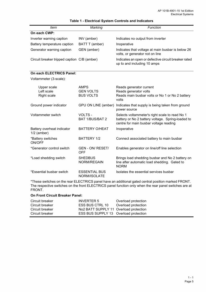
Item Marking FunctionOn each CWP:Inverter warning caption INV (amber) Indicates no output from inverterBattery temperature caption BATT T (amber) InoperativeGenerator warning caption GEN (amber) Indicates that voltage at main busbar is below 26
volts, or generator not on lineCircuit breaker tripped caption C/B (amber) Indicates an open or defective circuit breaker rated
up to and including 10 amps
On each ELECTRICS Panel:Voltammeter (3-scale):
Upper scale Left scale Right scale
AMPSGEN VOLTSBUS VOLTS
Reads generator currentReads generator voltsReads main busbar volts or No 1 or No 2 battery volts
Ground power indicator GPU ON LINE (amber) Indicates that supply is being taken from ground power source
Voltammeter switch VOLTS - BAT 1/BUS/BAT 2
Selects voltammeter's right scale to read No 1 battery or No 2 battery voltage. Spring-loaded to centre for main busbar voltage reading
Battery overheat indicator 1/2 (amber)
BATTERY O/HEAT Inoperative
*Battery switchesON/OFF
BATTERY 1/2 Connect associated battery to main busbar
*Generator control switch GEN - ON/ RESET/OFF
Enables generator on line/off line selection
*Load shedding switch SHEDBUSNORM/REGAIN
Brings load shedding busbar and No 2 battery on line after automatic load shedding. Gated to NORM
*Essential busbar switch ESSENTIAL BUSNORM/ISOLATE
Isolates the essential services busbar
*These switches on the rear ELECTRICS panel have an additional gated central position marked FRONT. The respective switches on the front ELECTRICS panel function only when the rear panel switches are at FRONT.On Front Circuit Breaker Panel:Circuit breakerCircuit breakerCircuit breakerCircuit breaker
INVERTER 5ESS BUS CTRL 10No2 BATT SUPPLY 11ESS BUS SUPPLY 13
Overload protectionOverload protectionOverload protectionOverload protection
1 - 1Page 5

Cockpit Controls and Indicators
1 - Pag
1 - 1 Fig 2 Cockpit Controls and Indicators
C/B
GEN
INV
BATT T
TEST
DAY
NIGHT
HS/TUC/1-1-fig2/0016
1e 6

AP 101B-4901-15 1st EditionElectrical Systems
18. Essential Services Busbar. The essential services busbar is supplied with power by two routes:
a. Via a diode, from the main busbar.
b. Via a contactor and a diode, from the battery busbar. This contactor is operated by selecting theESSENTIAL BUS switch to NORM (provided the crash switch has not tripped).
19. Load Shedding Busbar. The load shedding busbar is supplied, via a contactor, from the main busbar.The load shedding busbar is disconnected automatically (together with its loads) if main busbar volts reduceto below 26 volts in the air (e.g. if the generator fails); these electrical loads may then be altered by selectiveswitching and the busbar regained by selecting the SHED BUS switch, which is gated to NORM, to REGAIN.This action of the switch also reconnects No 2 battery to the main busbar. On the ground the weight switchrelays cause the undervolt detector to be bypassed and a connection between the main busbar and the loadshedding busbar is maintained.
20. AC Busbar. The 250 volt-ampere static inverter is fed automatically from the essential services busbar,via a circuit breaker labelled INVERTER (5) on the forward circuit breaker panel on the right in the frontcockpit (see Fig 2 and Fig 4); this inverter supplies the 115 volt, 400 Hz, single-phase AC busbar. Theservices supplied by the AC busbar are the normal cockpit instrument lighting and the servo altimeters. If theinverter fails, the amber INV caption on both CWP is illuminated. If the failure is due to an external fault,overload, etc, the inverter resets itself when the fault is removed. The INV captions then go out.
INDICATORS
21. Voltammeters. The voltammeters, one on each ELECTRICS panel in each cockpit, give continuousreadings on three separate scales of the following:
a. Generator total current load, on the top scale calibrated from 0 to 4 AMPS x 100 (inoperative duringstart).
b. GENerator voltage output, on the left scale calibrated from 10 to 36 VOLTS.
c. Main BUSbar voltage on the right scale calibrated from 10 to 36 VOLTS. BATtery 1 or BATtery 2voltages can also be read on this scale when selected by a VOLTS switch adjacent to the meter; theswitch is biased to its central (BUS) position.
22. Ground Power Indicators. The GPU ON LINE indicators, one on each ELECTRICS panel, are
illuminated when external ground power is being supplied.
23. Battery Overheat Indicators. The battery O/HEAT - 1/2 indicators, one on each ELECTRICS panel,are inoperative.
Circuit Breakers
24. The circuit breakers are shown in Fig 4. When a circuit breaker (rated up to and including 10 amps)trips, a C/B caption on the CWP is illuminated.
Crash Protection
25. Inertia Switches. Each of two inertia switches (below the front cockpit) has a dedicated crash relay.The normally closed contacts of these relays are in the actuation circuits for the line contactor, No 1 batterycontactor, No 2 battery contactor and the essential services busbar contactor. In a longitudinal decelerationof 4Q5g or more, the inertia switches close and energize the crash relays and the normally closed contactsopen. One relay de-energizes the contactor for No 1 battery and the line contactor; the other relay de-energizes the contactors for No 2 battery and the essential services busbar. Thus all power is removed fromall busbars, except the battery busbar which remains connected to the batteries.
1 - 1Page 7

NORMAL USE
Be
26reaswcon
27
28
29
30
1 - Pag
fore Flight
. Before carrying out the External checks ensure that the aircraft is electrically safe by checking that ther cockpit BATTERY and ESSENTIAL BUS switches are selected to FRONT, the front cockpit BATTERYitches are OFF and ESSENTIAL BUS switch is at ISOLATE and that the DC ground supply is notnected.
. Starting on Internal Batteries.
a. Check that all the rear cockpit switches are selected to FRONT.
b. With BATTERY 1 & 2 switches OFF check that the GEN switch is to ON/RESET and the SHED BUSswitch is to NORM. Select the ESSENTIAL BUS switch to NORM, check that CWP captions areilluminated; then select ISOLATE (captions out). Set BATTERY 1 & 2 switches ON and check that CWPcaptions are illuminated. Selectively switch first BATTERY 1 OFF then ON and then BATTERY 2 andcheck that each battery by itself gives a minimum reading of 24 volts. Leave both batteries set ON.
Note: If the battery voltage is above 24 volts the engine may be started using either the internal batteriesor a ground supply. If either battery voltage is between 24 and 22 volts a ground supply is to be usedfor starting. If either battery is below 22 volts a start is not to be attempted.
c. Select the ESSENTIAL BUS switch to NORM. Check that the GEN caption is illuminated and theINV and C/B captions are out.
. After Engine Starting on Internal Batteries.
a. Check that the GEN caption is out. If the GEN caption remains illuminated, set the GEN switch toOFF and back to ON/RESET and check that the caption goes out.
b. Check that GEN VOLTS and BUS VOLTS indicate between 27 and 29 volts.
. Before Engine Starting on Ground Supply.
a. Carry out the procedures at sub paras 27a and 27b but check that each battery gives a minimumreading of 22 volts and select BATTERY 1 & 2 switches OFF.
b. Have the ground supply plugged in and switched on. Check that the GPU ON LINE caption isilluminated and BUS VOLTS reads a minimum of 25 volts. Then switch BATTERY 1 & 2 ON and selectthe ESSENTIAL BUS switch to NORM.
c. Check the GEN caption is illuminated and that the INV and C/B captions are out.
Note: An engine start may be made with the battery voltage down to 22 volts; when the generator comeson line the batteries are to be allowed to charge for at least 20 minutes before a take-off is attempted.
. After Engine Starting on Ground Supply
a. Check that the GEN and GPU ON LINE captions are out.
b. Have the ground supply switched off and disconnected.
c. Check that the GEN VOLTS and BUS VOLTS indicate between 27 and 29 volts.
d. Check that both batteries are connected to the main busbar by checking that the BUS VOLTSindicates between 27 and 29 volts when the spring-loaded VOLTS switch is selected to BAT 1 and BAT2 in turn.
e. Before take-off ensure the AMPS indication does not exceed 100 amps (with landing lamp OFF).
1e 8

AP 101B-4901-15 1st EditionElectrical Systems
In Flight
31. In flight, check that the GEN, INV, and C/B captions remain out, that GEN VOLTS and BUS VOLTSindicate between 27 and 29 volts and that there is no abnormal unexplained AMPS reading (normally about80 amps with landing lamp ON).
After Flight
32. During the Shutdown Checks, switch off all electrical services and then, a minimum of five secondsafter RPM have decreased below 10%, switch OFF the BATTERY switches. The ESSENTIAL BUS switchis to be set to ISOLATE and all rear cockpit switches set to FRONT. If the GEN caption remains illuminatedafter shutdown, select the SHED BUS switch to NORM.
USE IN ABNORMAL CONDITIONS
Ground Supply Contactor Failure
33. If the GPU ON LINE light remains on when the generator is brought on line (GEN caption out), powerfrom the aircraft batteries is not available and the aircraft is not to be flown.
Generator Failure
34. Generator failure is indicated by the GEN caption being illuminated. Set the GEN switch to OFF andback to ON/RESET to bring the generator back on line. If the fault was transient the GEN caption goes out;if it does not, select the GEN switch to OFF. If, in the air, the generator does not reset, No 1 battery onlysupplies all electrical loads on the main busbar and No 1 and No 2 batteries jointly supply the essentialservices and battery busbars. Only the services connected to the load shedding busbar are lost.
35. Following the loss of the generator in the air, bus voltage decreases immediately to that of the No 1battery, i.e. approximately 24 volts, No 2 battery having been automatically disconnected from the mainbusbar by the undervoltage detector together with the load shedding busbar. Select off or leave off any ofthe services on the load shedding busbar that are not required. Select the SHED BUS switch to REGAIN;this makes the services on the load shedding busbar available again (see Table 2 for loads) and reconnectsNo 2 battery to the main busbar. Monitor battery volts. Land as soon as possible because battery operationof the essential loads cannot be guaranteed for more than 30 minutes. Shutdown the engine when clear ofthe runway.
Inverter Failure
36. Inverter failure is indicated by the INV caption being illuminated. Check the INVERTER circuit breaker(5). If the circuit breaker is tripped, wait ten seconds and then reset; check that the INV caption goes out. Ifthe circuit breaker is made, pull and reset and check that the INV caption goes out. If the caption remainson pull the circuit breaker and do nothing further to regain the inverter. The following services are lost:
a. Normal cockpit instrument lighting.
b. Electroluminescent panels.
c. Servo altimeters.
d. All heading references (except the standby compass).
e. Horizontal situation indicator bearing needles.
f. Traffic Alert and Collision Avoidance System (TCAS).
1 - 1Page 9 (AL 1)

Circuit Breakers
WAwircirc
37maor
Es
38esssertormaareonsysmothr
1 - Pag
RNING: If more than one circuit breaker trips this may indicate an electrical fault which may lead to aing loom fire or overheat. Do not attempt to reset the circuit breakers. Land as soon as possible. If trippeduit breakers are accompanied by smells, smoke or fumes carry out the FRC Smoke or Fumes drill.
. It is permissible to reset a circuit breaker in flight after waiting ten seconds; only one attempt is to bede to regain a system. A circuit breaker is not to be reset if it trips a second time. If service lost is criticalcaption remains on and cause cannot be positively identified, land as soon as practicable.
sential Busbar Failure
. The Pre-Start electrical panel checks are designed to check the two routes for the power supply to theential services busbar. If, having followed the checks, both routes are shown to be satisfactory, essentialvices busbar failure has a low probability. If the essential services busbar does fail (unique indications:que 100%, RPM zero, turn-and-slip and standby AI flags showing), intercom and radio fail, there is arked reduction in engine torque, there are no CWP warnings or cockpit lighting and many other services lost. Check the ESS BUS CONTROL (10) and ESS BUS SUPPLY (13) circuit breakers and reset (once
ly) if necessary. If the busbar cannot be regained, land as soon as possible using the standby loweringtem to lower the landing gear. Note the flap position in order to plan the type of approach. Limit throttlevement as the EGT limit in MANual is 560LC and the EGT gauge is inoperative. Do not use REVerseust on landing or on shutdown.
1e 10

AP 101B-4901-15 1st EditionElectrical Systems
▲▲▲▲▲
▼▼▼▼▼
STARTER FIELD DC GROUNDGENERATOR COIL SUPPLY
28V 6KW
GENERATORON/RESET - OFF
AMMETERRELAY
60% CHANGEOVER
OVER 32VDETECTOR
STARTERON
GEN
BATTERYCONTACTOR
NO 2NO 1
GENERATOR CONTROLAND PROTECTION UNIT
ENGINESTART
FIELD
CRASHSWITCH
LINECONTACTOR
GND SUPPLYCONTACTOR
GPUSLAVERELAY
GPUON LINE
LINECONTACTOR
MAIN BUSBAR
CUITSRCUITS CIRCUITS
AIR
GROUND
LOAD SHEDDING BUSBAR
LOADS
SHED BUS SWITCHNORM/REGAIN
SHED BUSCONTACTOR
VOLTAGE REGULATOR(OVER 31V)
REVERSE CURRENTDETECTOR (MINUS 10A)
1 - 1Page 11
Electrical Power Distribution - Simplified
1 - 1 Fig 3 Electrical Power Distribution - Simplified
▼▼▼▼▼
▼▼▼▼▼
▼▼▼▼▼
▲▲▲▲▲
▼▼▼▼▼
▼▼▼▼▼
▼▼▼▼▼
▲▲▲▲▲
▼▼▼▼▼
▼▼▼▼▼
NO 1 BATTERY NO 2 BATTERY24V 24 AMP-HOUR 24V 24 AMP-HOUR
A B VOLTS AMPS
DIODE
CB 131 CB 11
DIODEVOLTMETER
SWITCH
GND SUPPLYCONTACTOR
GND SUPPLYCONTACTOR AIR
GROUND
A B
NO 1BATTERYSWITCH
NO 2BATTERYSWITCH
UNDERVOLTDETECTOR(26V)
BATTERY BUSBAR
CB 10 CB 13 LOADS
CRASHSWITCH
CRASHSWITCH
CRASHSWITCH
NO 1BATTERY
CONTACTOR
NO 2BATTERY
CONTACTOR
AIRGROUND
SHED BUS SWITCHNORM/REGAIN
MAIN BUSBAR
LOADS LOADS
ESSENTIAL SERVICES BUSBAR
BATTERY BUSBAR
115V AC BUSBAR
LOADS
ESSENTIAL BUS SWITCHNORM/ISOLATE
ESSENTIALSERVICES
CONTACTOR
DIODE DIODE
HOLD OFFRELAY
STATICINVERTER INV
POWER OFFAIRCRAFT ON GROUND
SUPPLY CIRCONTROL CIREFERENCE
CB 5

Circuit Breaker Panels
Rear Cockpit
1 - 1 Fig 4 Circuit Breaker Panels
Front Cockpit
NOTE: For the key to circuit breaker identification numbers, see Table 2.
1 - 1Page 12

AP 101B-4901-15 1st EditionElectrical Systems
Table 2 - Busbar Loads
LOAD SHEDDING BUSBARCB Load Amps CB Load Amps
*132 Taxi lamp 16Q0 * 72 Air Conditioning 2Q0* 133 Landing lamp (left) 16Q0 67 Propeller heater control 1Q0* 134 Landing lamp (right) 16Q0 74 Fuel flow indicators 0Q7* 80 Propeller heater 12Q0 * 73 Engine intake anti-ice 0Q5* 66 AOA heater 8Q0 71 Rear pitot static indicator 0Q2* 68 Rear pitot static heater 4Q5 69 AOA heater fail indicator 0Q1* 70 Strobes 4Q5 75 Servo altimeter vibrator 0Q1* These items may be isolated/regained by selective switching
28V DC ESSENTIAL SERVICES BUSBARCB Switchable Load Amps CB Switchable Load Amps53 Flap motor supply 20Q0 62 Rear cockpit background lamps 0Q8747 Fuel pump starboard main 6Q5 52 Flap motor control 0Q548 Fuel pump port auxiliary 6Q5 ** 4 Microphone and emergency tels amplifiers 0Q539 Dim/test units 3Q0 20 Transponders 0Q521 U/VHF system 1Q0 **6 Front cockpit emergency lamps 0Q1563 Front cockpit background lamps 0Q87 **7 Rear cockpit emergency lamps 0Q15
CB Non-Switchable Load Amps CB Non-Switchable Load Amps**1 Engine start control 1Q5 31 AOA & stall warning 2Q0**2 Ignition 4Q5 32 Beta baulk retraction 2Q0**3 Unfeathering pump 2Q0 33 Oxygen indicators 0Q1**5 Inverter 2Q7 34 EGT amplifier 0Q1**8 Central warning system 0Q2 35 RPM gauges 0Q25**9 Stick Shaker 1Q0 36 Fire detection 0Q3 14 Circuit breaker tripped caption 0Q2 37 Oil pressure indicators 0Q1
15 Front CCS station box 0Q5 38 Accident data recorder 3Q0 19 Rear CCS station box 0Q5 40 Landing gear position indicator 0Q2 22 Front combined speed indicator 0Q1 41 Landing gear control 0Q5 23 Rear combined speed indicator 0Q1 43 Oil pressure warning indicator 0Q1 24 Front turn & slip indicator 0Q1 44 Oil temp indicators 0Q1 25 Rear turn & slip indicator 0Q1 45 Hyd press warning 2Q0 26 Front standby altimeter 0Q1 46 Fuel press warning indicator 0Q2 27 Rear standby altimeter 0Q1 49 Low fuel warning 0Q2 28 Front standby attitude indicator 0Q1 50 Trim tab indicators 0Q2 29 Rear standby attitude indicator 0Q1 51 Flap position indicator 0Q1**These items are on the front cockpit forward circuit breaker panel
1 - 1Page 13

C108586109596971111
C87888990919293989910
C**1
**1
1212
C**1
**T
1 - Pag
28V DC MAIN BUSBARB Switchable Load Amps CB Switchable Load Amps
3 Ice detection system 10Q0 94 Airbrake control and indication 3Q0Fuel pump left main 6Q5Fuel pump right auxiliary 6Q5 107 Navigation lights 3Q0
0 Front pitot static heater 4Q5 106 Landing/taxi lights control 2Q0Elevator trim 4Q5 119 Tacan 1Q5Aileron trim 4Q5 118 VHF navigation receiver 1Q2Rudder trim 4Q5 104 Pitot static heat auto control 0Q6
2 Front seat position motor 4Q0 108 Front utility lamp 0Q153 Rear seat position motor 4Q0 109 Rear utility lamp 0Q15
B Non-Switchable Load Amps CB Non-Switchable Load AmpsFuel contents indicators 0Q2 102 OAT indicator 0Q1Front cockpit HSI 0Q1 105 Trim control 0Q1Rear cockpit HSI 0Q1 111 Canopy unlocked indicators 0Q1Front cockpit TCAS 2.0 110 Parking brake indicators 0Q5Rear cockpit TCAS 2.0 114 DC power control 0Q5Power supply socket 0Q2 115 UHF/VHF No1 and No 2 4Q0Inverter fail indicator 0Q2 116 UHF/VHF, UUPI & tone generator 4Q0Front attitude indicator 0Q55 117 Directional gyro 2Q0Rear attitude indicator 0Q55 120 Navigation changeover 0Q7
1 Front pitot static indicator 0Q2 136 Essential services busbar supply Bus Load
28V DC BATTERY BUSBARB Switchable Load Amps CB Switchable Load Amps0 Essential services busbar
contactor2Q0 129 No 1 battery contactor 2Q0
3 Essential services busbar supply Bus 130 No 2 battery contactor 2Q0Load 137 No 1 battery voltameter switch 0Q0
7 Fuel/hyd cut off 2Q0 138 No 2 battery voltameter switch 0Q08 Load shedding busbar contactor 2Q0 139 CPU control 1Q0
B Non-Switchable Load Amps CB Non-Switchable Load Amps1 No 2 battery busbar supply Bus
Load131 No 1 battery busbar supply Bus
Loadhese items are on the front cockpit forward circuit breaker panel
1e 14

AP 101B-4901-15 1st EditionCentral Warning System
PART 1
CHAPTER 2 - CENTRAL WARNING SYSTEM
ContentsPara
Illustrations Fig
INTRODUCTION
General
1. The central warning system (CWS) gives warnings of failures or events in the aircraft systems whichrequire prompt action to ensure the safety of the aircraft. The CWS consists of a central warning panel(CWP) and two attention getters in each cockpit, and an audio warning unit which operates through theheadphones.
2. The failures and events appear as red or amber captions on the CWP. The red captions areaccompanied by an audio warning; they indicate a more hazardous condition than those signified by amber
INTRODUCTIONGeneral… … … … … … … … … 1
DESCRIPTIONCentral Warning Panel … … … … … … 3Attention Getters … … … … … … … 7Fire Detection and Warning … … … … … … 8Audio Warning… … … … … … … … 12
NORMAL USEBefore Flight … … … … … … … … 13After Flight … … … … … … … … 15
USE IN ABNORMAL CONDITIONSAudio Warning… … … … … … … … 16
CWP and Attention Getters (Front and Rear Cockpits) … … 1
captions. Each caption is illuminated by two single filament lamps whenever the captions control circuit isactivated by the associated aircraft system exceeding a limitation or deviating from normal operatingparameters. When appropriate remedial action is taken the CWS resets itself; it is self cancelling if activatedby transient failures or events. Power for the CWS is supplied from the essential services busbar. A circuitbreaker (labelled CWP) in the power supply line is on the forward circuit breaker panel on the right in the frontcockpit.
DESCRIPTION
Central Warning Panel
3. A CWP (Fig 1) is on the right hand side of the lower main instrument panel in each cockpit and thecaptions and their meanings are listed in Table 1.
4. The layout of the captions on each CWP is identical, and in the event of a hazardous condition or a failureof any of the systems being monitored, identical captions are lit on both panels.
5. Test Switch. A TEST switch is on each CWP. The switch is spring-loaded from TEST to the centre (off)position. When selected and held to TEST, a supply from the essential services busbar is fed to the CWPand the filaments of all unlit captions on both CWP illuminate, the attention getters in both cockpits flash andthe audio warning sounds in the headsets; the test switch also activates all other unlit warning and
1 - 2Page 1 (AL 1)

information captions in the cockpits (except the MARKER light). When the switch is released, all captionswhcanau
6.(AOexccap
Att
7.canthecangegethe
Fir
8.temthe
9.chabu
10con
11cocsel
Au
12gege
NoThSyCh
1 - Pag
ich were not lit before TEST was selected go out and the attention getters and the audio warning arecelled. If, while the switch is held at TEST, an attention getter is pressed, the attention getter and the
dio warning are cancelled.
Day/Night Switch. A DAY/NIGHT switch is on each CWP. When selected to NIGHT, the angle-of-attackA) indexer (removed post-SM109 (FLARM)) and all cockpit warning and information captions, with theeption of the red captions (and MARKER light), operate at a reduced intensity. When selected to DAY alltions operate at normal intensity.
ention Getters
The two attention getters in each cockpit are integrally lit, spring-loaded panels which incorporate acelling facility. When a CWS control circuit is activated, both attention getters in each cockpit flash and caption associated with the fault is illuminated on the CWP. Pressing any one of the attention getterscels all attention getters but the caption associated with the fault remains illuminated. If, after the attention
tters have been manually cancelled, the CWS circuits are activated by another fault condition the attentiontters resume flashing. If the flashing circuit fails to operate when the CWS control circuits are operated, attention getter lights remain on steady.
e Detection and Warning
An integrity-monitoring fault free fire detection (FFFD) and warning system is linked to the CWS. Aperature-sensitive firewire is fitted around the exhaust flange and the engine support frame adjacent to
hot section; the firewire connects with a control unit behind the firewall.
Resistance and capacitance in the firewire change with temperature; above a critical temperature theynge sufficiently to trigger the control unit. The unit then connects power from the essential services
sbar to illuminate the FIRE caption (red) on the CWP.
. If a system defect occurs which impairs the capability to provide operational warning of a fire or overheatdition, the control unit illuminates the FIRE DET caption (amber) on the CWP.
. Test Facility. A FIRE DETect test switch is on the lower right of the main instrument panel in eachkpit. When held at FIRE TEST and FAULT TEST in turn, full operational warnings for the respective
ections confirm serviceability of the system.
dio Warning
. When a failure or an event associated with a red CWP caption activates the CWS control circuits, a tonenerator provides an audio warning (swept tone) in the headphones in each cockpit. Pressing any attentiontter cancels this audio warning.
te: A different audio warning (pulsed tone) is activated by other systems not associated with the CWS.ese are overspeed, high g and high AOA. This warning is described under Communications Controlstem in Chapter 13 (see also Stall Warning in Chapter 6). TCAS aural warnings are outlined inapter 13.
2e 2

AP 101B-4901-15 1st EditionCentral Warning System
Table 1 - Central Warning Panel Captions.
RED CAPTIONSCaption Indicating
FIRE Fire in the engine bayOXY Low oxygen pressure (below 3Q1 bar to 3Q45 bar)
AMBER CAPTIONSCaption Indicating
CANOPY Canopy unlockedOIL P Low engine oil pressure (below 2Q8 bar) (subject to 20-second delay)C/B Open or defective circuit breaker*HYD Hydraulic oil low pressure (below 158Q6 bar) or hydraulic oil high temperature (above
107LC)EMER HYD Low emergency hydraulic pressure (below 158Q6 bar) or emergency shut-off valve
has failed to close after take-offFUEL P Low fuel pressure (below 0Q41 bar) or individual pump failureLOW FUEL Low fuel content (below 35 kg in either tank)GEN DC generator off line or failure or output below 26 voltsINV Inverter failurePSV HEAT Pitot, static, stall warning vane or AOA vane heater failureEEC Engine electronic control defect (or manual mode selected)AIR COND Air conditioning failure (over pressure 7Q3 m 0Q3 bar) (over temperature 90 m 5LC)F DET Fire detection failure BATT T InoperativeFUEL FLTR Pressure drop across fuel filter in excess of 0Q0964 bar* Only circuit breakers rated up to and including 10 amps
1 - 2Page 3
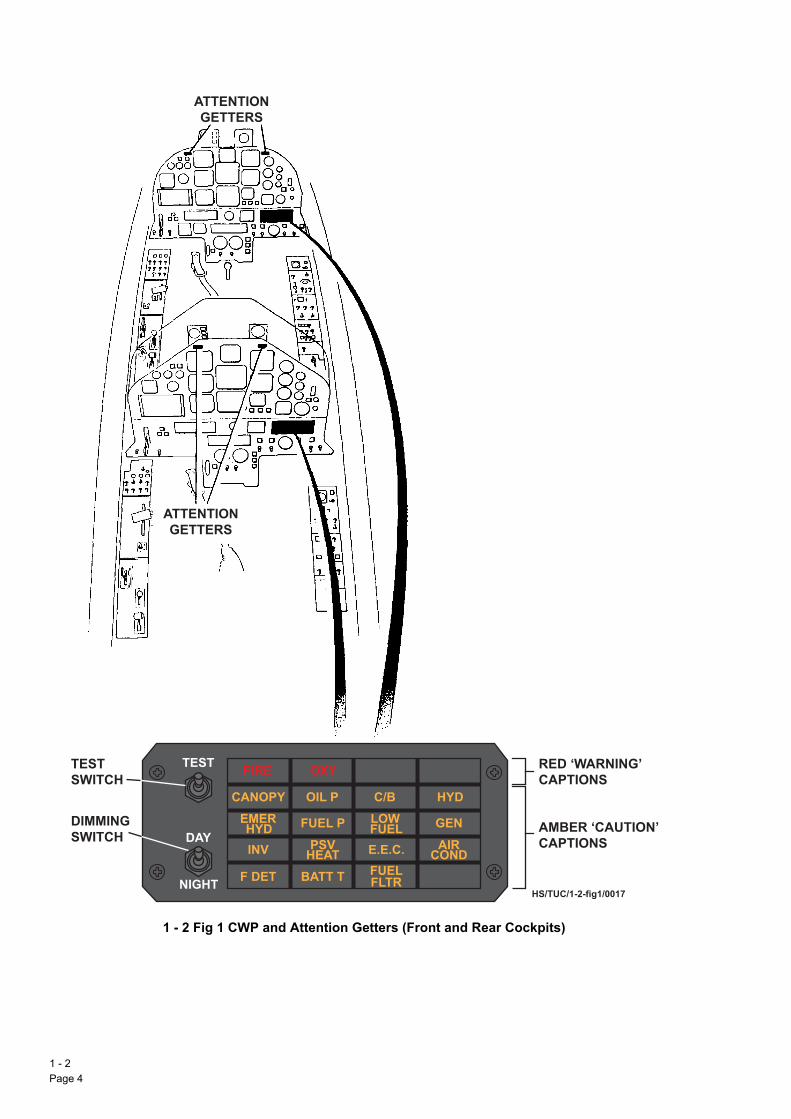
CWP and Attention Getters (Front and Rear Cockpits)
1 - Pag
ATTENTIONGETTERS
ATTENTIONGETTERS
1 - 2 Fig 1 CWP and Attention Getters (Front and Rear Cockpits)
FIRE OXY
CANOPY OIL P C/B HYDEMERHYD FUEL P LOW
FUEL GEN
INV PSVHEAT E.E.C. AIR
CONDF DET BATT T FUEL
FLTR
TEST
DAY
NIGHTHS/TUC/1-2-fig1/0017
TESTSWITCH
DIMMINGSWITCH
RED ‘WARNING’CAPTIONS
AMBER ‘CAUTION’CAPTIONS
2e 4

AP 101B-4901-15 1st EditionCentral Warning System
NORMAL USE
Before Flight
13. Before starting the engine, when either the batteries are switched ON or external power is connectedand switched on, check that the CANOPY, OIL P, HYD, FUEL P and GEN captions are illuminated. Checkthat when a CWP test switch is held at TEST, all unlit captions on both CWP are illuminated, the attentiongetters and audio warning tone are activated and all other warning and information lights in the cockpit(except the MARKER light) are illuminated. Select the FIRE DET switch to FIRE TEST and check that theFIRE caption is illuminated and attention getters and audio warning tone are activated; select to FAULT TESTand check that the F DET caption is illuminated and the attention getters are activated. When the testswitches are released, check that all indications revert to the pre-test state, the audio warning ceases andthe attention getters extinguish.
Note: If the aircraft hydraulic system has been serviced before flight, the EMERG HYD caption is alsoilluminated when power is switched on.
14. After starting the engine check that all CWP captions are out.
After Flight
15. After landing select the FIRE DET switch to FAULT TEST and check that the F DET caption is illuminatedand then goes out when the switch is released.
USE IN ABNORMAL CONDITIONS
Audio Warning
16. An electrical fault within the CWS can cause an audio warning to sound continuously and in isolation.Radio communication is affected.
17. If, during a flight, a g exceedance activates the audio warning, the warning self cancels as soon as theexceedance ceases; however, the audio warning is subsequently reactivated as soon as engine RPMdecrease below 90%. This normally occurs after landing but also occurs if the engine is shut down in flight(e.g. fire or mechanical failure). The audio warning sounds continuously until the DAPU is dumped post flight.
18. A continuous audio stall warning (except speed and g exceedance) may be silenced by pulling circuit
breaker 31 (AOA indicator); all AOA information and the audio stall warning are then lost. The stick shakerremains operative in the approach configuration.
19. The audio warning can also be silenced by pulling circuit breaker 4 (MIC/TEL); however, if this is done,the main U/VHF radio is inoperative and the standby UHF radio must be selected. The AOA indicatorremains operative. If the CCS station box amplifier selector is at FAIL all communication is lost if c/b 4 ispulled.
1 - 2Page 5

1 - Pag
Intentionally Blank
2e 6

AP 101B-4901-15 1st EditionFuel System
PART 1
CHAPTER 3 - FUEL SYSTEM
ContentsPara
Illustrations Fig
INTRODUCTIONGeneral… … … … … … … … … 1
DESCRIPTIONFuel Tanks … … … … … … … … 2Fuel Transfer … … … … … … … … 4Tank Venting … … … … … … … … 7Fuel Feed … … … … … … … … 8Booster Pumps … … … … … … … 9LP Shut-Off Valve … … … … … … … 14Fuel Low Level Warning … … … … … … 15Controls and Indicators … … … … … … 16Refuelling … … … … … … … … 17Defuelling … … … … … … … … 19Draining … … … … … … … … 20
NORMAL USE AND MANAGEMENTBefore Flight … … … … … … … … 21In Flight… … … … … … … … … 22
USE IN ABNORMAL CONDITIONSFuel Pressure Failure… … … … … … … 23Fuel Filter Blockage … … … … … … … 25Low Fuel Level … … … … … … … 26
Fuel System General Layout… … … … … … 1Fuel System Schematic … … … … … … 2Fuel System Controls and Indicators … … … … 3
INTRODUCTION
General
1. Fuel is stored in one integral tank in each wing. Each tank has two cells and a collector tank. The tanksare gravity refuelled or defuelled, and have a pressure defuel facility for use in emergency. Booster pumps,associated with each tank, maintain a constant supply of fuel to the engine at low pressure in any approvedflight attitude.
DESCRIPTION
Fuel Tanks
2. The inboard cell of each fuel tank extends from the wing root along the wing leading edge. The outboardcell is offset to the rear and occupies the inter-spar area (Fig 1). Each inboard cell has a collector tankcontaining 9Q6 kg, which ensures a fuel supply to the booster pumps during aerobatic manoeuvres. Theminimum guaranteed capacity of usable fuel in each tank is 277 kg. The amount of fuel is measured by acapacitance type gauging system.
3. Residual Fuel. Residual (unusable) fuel, not included in the guaranteed minimum, is 3Q63 kg.
1 - 3Page 1

Fuel Transfer
4.a f
5.dri
6.thama Fuel System General Layout
Ta
7.ouprois nvalNAthr
Fu
8.commo
Bo
9.au
10maser
1 - Pag
Outer Cell to Inner Cell. Fuel flows by gravity from the outer cell to the inner cell via transfer pipes andlap-type non-return valve (NRV), which restricts the flow of fuel outboard.
Inner Cell to Collector Tank. Fuel is sucked into the collector tank from the inner cell by an ejector pumpven by primary fuel pressure.
Collector Tank to Booster Pumps. A shuttle valve in each collector tank is gravity operated to ensuret, in normal flight, fuel is drawn from the bottom of the tank. In negative g conditions the shuttle valveintains the fuel supply from the top of the tank.
1 - 3 Fig 1 Fuel System General Layout
nk Venting
Each tank has a vent pipe which runs from the inner end of the inboard cell to the outer end of thetboard cell, and thence to a NACA opening in the wing under-surface. A NRV at each end of the pipevides ventilation during inverted flight and manoeuvres, and prevents fuel entering the pipe; however, itot unusual for a small amount of residual fuel to be seen venting after inverted spin recovery. A relief
ve in the outer cell discharges tank excess pressure. A flame arrestor, between the outboard vent and the
CA opening, protects the vent pipe from fire due to electrical discharges. Inter-cell venting is providedough transfer pipes.
el Feed
Fuel is supplied, from the collector tanks in each inner cell via booster pumps (main or auxiliary), to amon supply pipe and thence to the engine (see Fig 2). The supply pipe incorporates a relief valve, filter,
torized shut-off valve and a pressure switch.
oster Pumps
A main booster pump besides each tank delivers fuel, at low pressure, to the common supply pipe. Anxiliary booster pump is connected in parallel with each main pump.
. Power Supplies. Electrical supplies for the left main pump and right auxiliary pump are taken from thein busbar. Supplies for the right main pump and the left auxiliary pump are taken from the essentialvices busbar.
3e 2
AP 101B-4901-15 1st EditionFuel System
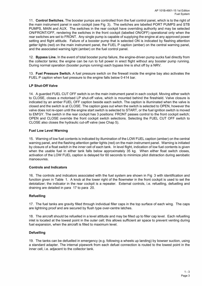
11. Control Switches. The booster pumps are controlled from the fuel control panel, which is to the right ofthe main instrument panel in each cockpit (see Fig 3). The switches are labelled PORT PUMPS and STBPUMPS, MAIN and AUX. The switches in the rear cockpit have overriding authority and may be selectedON/FRONT/OFF, rendering the switches in the front cockpit (labelled ON/OFF) operational only when therear switches are set to FRONT. Any single pump is capable of supplying the engine at any approved powersetting and flight attitude. Failure of a booster pump that is selected ON is indicated by flashing attentiongetter lights (red) on the main instrument panel, the FUEL P caption (amber) on the central warning panel,and the associated warning light (amber) on the fuel control panel.
12. Bypass Line. In the event of total booster pump failure, the engine-driven pump sucks fuel directly fromthe collector tanks; the engine can be run to full power in erect flight without any booster pump running.During normal operation (booster pumps running) each bypass line is shut off by a NRV.
13. Fuel Pressure Switch. A fuel pressure switch on the firewall inside the engine bay also activates theFUEL P caption when fuel pressure to the engine falls below 0Q414 bar.
LP Shut-Off Valve
14. A guarded FUEL CUT OFF switch is on the main instrument panel in each cockpit. Moving either switchto CLOSE, closes a motorised LP shut-off valve, which is mounted behind the fireshield. Valve closure isindicated by an amber FUEL OFF caption beside each switch. The caption is illuminated when the valve isclosed and the switch is at CLOSE. The caption goes out when the switch is selected to OPEN, however thevalve does not re-open until the engine start switch is selected to START, or the fuel ignition switch is movedto EM4GY. The switch in the rear cockpit has 3 positions: FRONT passes control to the front cockpit switch;OPEN and CLOSE override the front cockpit switch selections. Selecting the FUEL CUT OFF switch toCLOSE also closes the hydraulic cut-off valve (see Chap 5).
Fuel Low Level Warning
15. Warning of low fuel contents is indicated by illumination of the LOW FUEL caption (amber) on the centralwarning panel, and the flashing attention getter lights (red) on the main instrument panel. Warning is initiatedby closure of a float switch in the inner cell of each tank. In level flight, indication of low fuel contents is givenwhen the usable fuel in either tank falls below approximately 35 kg. When either float switch closes,activation of the LOW FUEL caption is delayed for 60 seconds to minimize pilot distraction during aerobaticmanoeuvres.
Controls and Indicators
16. The controls and indicators associated with the fuel system are shown in Fig 3 with identification andfunction given in Table 1. A knob at the lower right of the flowmeter in the front cockpit is used to set thedetotalizer; the indicator in the rear cockpit is a repeater. External controls, i.e. refuelling, defuelling anddraining are detailed in para 17 to para 20.
Refuelling
17. The fuel tanks are gravity filled through individual filler caps in the top surface of each wing. The capsare lightning proof and are secured by flush type over-centre latches.
18. The aircraft should be refuelled in a level attitude and may be filled up to filler cap level. Each refuellinginlet is located at the lowest point in the outer cell; this allows sufficient air space to prevent venting duringfuel expansion, when the aircraft is filled to maximum level.
Defuelling
19. The tanks can be defuelled in emergency (e.g. following a wheels up landing) by bowser suction, usinga standard adapter. The internal pipework from each defuel connection is routed to the lowest point in theinner cell, i.e. adjacent to the collector tank.
1 - 3Page 3

Draining
20valthe
Be
21thetheflow
In
22asysenapcrois i
CAres
No
Fu
23or ma
24arechecapelimg m
Fu
25bypcomto
Lo
26assmo
1 - Pag
. The fuel system may be drained by gravity down to undrainable fuel level (0Q8kg) by opening drainves, one at the base of each collector tank. During draining, venting of the tanks is improved by opening filler caps.
NORMAL USE AND MANAGEMENT
fore Flight
. Ensure that the rear cockpit FUEL CUT OFF switch is to FRONT during the Cockpit checks and, during Pre-Start checks, that the front cockpit switch has the cover down. During the Pre-Start checks, check fuel contents, and test each booster pump, its associated indicator and the FUEL P caption. Confirm themeter reads zero and set the fuel detotalizer.
Flight
. Monitor the fuel contents. Fuel asymmetry may arise particularly if the aircraft is flown with sideslip; themmetry can be corrected by selective use of the booster pumps. Since the gauge readings are verysitive to sideslip, trim out sideslip before taking readings. When the indicated fuel contents fall to
proximately 35kg on either side, the LOW FUEL caption is illuminated; check the fuel contents gauge andss check fuel usage against the detotalizer and elapsed flight time. The gauges overread when the aircraftn a nose-up attitude and underread when nose down.
UTION: Fuel gauges should be monitored carefully to safeguard against the effects of preferential flowulting from mismatched booster pumps.
te: For take-off and landing select at least one booster pump on each side.
USE IN ABNORMAL CONDITIONS
el Pressure Failure
. The FUEL P caption comes on when fuel pressure at the entry to the fuel control unit falls below datum,when any selected booster pump does not provide fuel pressure above its datum. The loss of pressurey also be due to a fuel leak or a partially closed fuel cock.
. Following illumination of the FUEL P caption, check the fuel pump captions. If no fuel pump captions lit, reduce power to the minimum practicable, select all booster pumps ON (failure indicators out) andck that the fuel contents are normal. Avoid negative g and land as soon as possible. If a fuel pump
tion is lit, select the other pump on the failure side and switch OFF the failed pump. If this selectioninates the warning continue the sortie; if not, maintain power at the minimum practicable, avoid negativeanoeuvres and land as soon as possible. Monitor the apparent rate of fuel consumption.
el Filter Blockage
. Impending bypass of the fuel filter is indicated when the FUEL FLTR caption comes on. When theass valve opens unfiltered fuel is routed past the filter to the fuel control unit. If the FUEL FLTR captiones on reduce the fuel flow by reducing power to the minimum practicable (e.g. if essential for safety, up
full power may be used). Land as soon as practicable.
w Fuel Level
. If the LOW FUEL caption comes on, check the fuel contents. If both sides indicate more than 35kg,ume that only 35kg usable remain in each side. If one side indicates 35kg and the other side indicatesre, attempt to balance the fuel by selective switching of the booster pumps.
3e 4

AP 101B-4901-15 1st EditionFuel System
Fuel System Schematic
TEST
FUEL P LOWFUEL
FUELFLTR
DAY
NIGHT
CENTRAL WARNING PANEL
KEY
SUCTION FEED
PRESSURE SUPPLY
FUEL/AIR TRANSFER
TANK VENT SYSTEM
RETURN TO TANK
PRESSURE RELEASE
ELECTRICAL SIGNAL
FUEL FLOW TRANSMITTER
ENGINE
SHUT-OFF VALVE
FILTER
THERMAL RELIEF VALVE
LEFTMAINPUMP LEFT
AUXILIARYPUMP
PRESSURE DEFUELCONNECTION
MANUALSHUT-OFF
VALVE
FILTER
PRIMARYFUEL FLOW
LOWGRAVITY FILLER
FUEL CONTENTS
RIGHTMAINPUMP
PRESSURESWITCH
RIGHTAUXILIARY
PUMP
RESPECTIVE BOOSTER PUMPINDICATOR (FUEL CONTROL PANEL)
FIREWALL
DRAIN
DIFFERENTIALPRESSURE SWITCH
NON-RETURN VALVE
PRESSURE SWITCH
BYPASS VALVE
1 - 3 Fig 2 Fuel System Schematic
EJECTOR PUMP
COLLECTORTANK
FUEL SENSOR
SHUTTLE INTAKEVALVE
FLAP VALVE(NON-RETURN) DRAIN VALVE
NON-RETURNVALVE (OUTER)
RIGHT TANKLEFT TANK
NACA AIR INLET
RELIEFVALVE
TRANSMITTER
FLAP VALVE(NON-RETURN)
FLAMEARRESTOR
VENT
INNERCELL INNER
CELL
NON-RETURNVALVE (INNER)
OUTERCELL
OUTERCELL
1 - 3Page 5
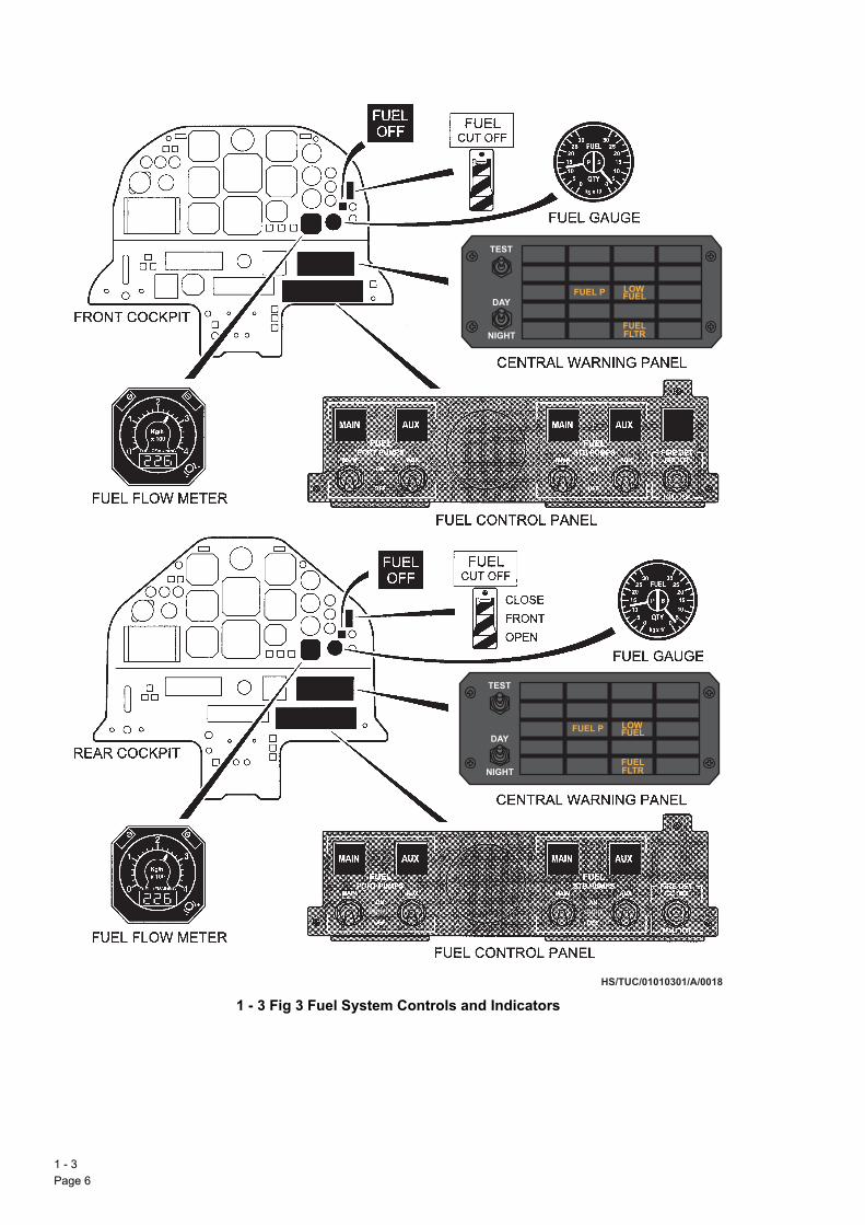
Fuel System Controls and Indicators
1 - Pag
FUEL P LOWFUEL
FUELFLTR
TEST
DAY
NIGHT
FUEL P LOWFUEL
FUELFLTR
TEST
DAY
NIGHT
1 - 3 Fig 3 Fuel System Controls and Indicators
FRONT FRONT
HS/TUC/01010301/A/0018
3e 6
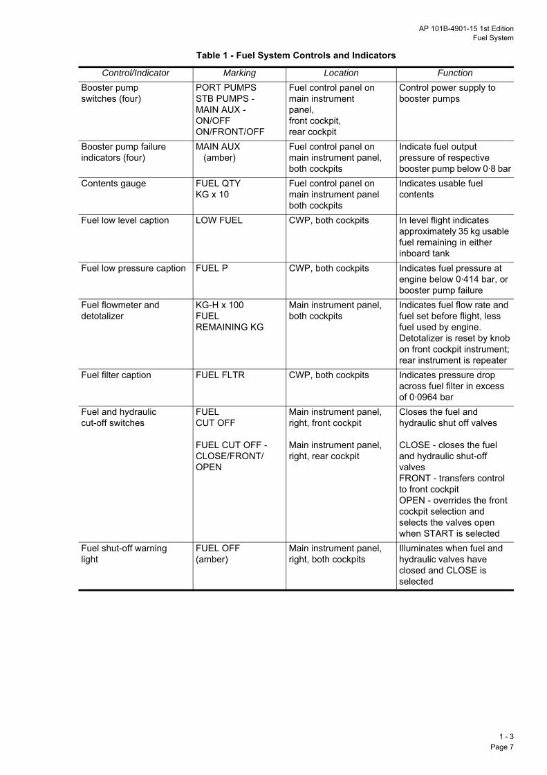
AP 101B-4901-15 1st EditionFuel System
Table 1 - Fuel System Controls and Indicators
Control/Indicator Marking Location FunctionBooster pump switches (four)
PORT PUMPSSTB PUMPS -MAIN AUX -ON/OFFON/FRONT/OFF
Fuel control panel onmain instrumentpanel, front cockpit,rear cockpit
Control power supply to booster pumps
Booster pump failureindicators (four)
MAIN AUX (amber)
Fuel control panel on main instrument panel, both cockpits
Indicate fuel output pressure of respective booster pump below 0Q8 bar
Contents gauge FUEL QTYKG x 10
Fuel control panel on main instrument panel both cockpits
Indicates usable fuel contents
Fuel low level caption LOW FUEL CWP, both cockpits In level flight indicates approximately 35 kg usable fuel remaining in either inboard tank
Fuel low pressure caption FUEL P CWP, both cockpits Indicates fuel pressure at engine below 0Q414 bar, orbooster pump failure
Fuel flowmeter and detotalizer
KG-H x 100FUELREMAINING KG
Main instrument panel,both cockpits
Indicates fuel flow rate and fuel set before flight, less fuel used by engine.Detotalizer is reset by knobon front cockpit instrument;rear instrument is repeater
Fuel filter caption FUEL FLTR CWP, both cockpits Indicates pressure dropacross fuel filter in excess of 0Q0964 bar
Fuel and hydrauliccut-off switches
FUELCUT OFF
FUEL CUT OFF -CLOSE/FRONT/OPEN
Main instrument panel,right, front cockpit
Main instrument panel,right, rear cockpit
Closes the fuel and hydraulic shut off valves
CLOSE - closes the fuel and hydraulic shut-off valves
FRONT - transfers controlto front cockpitOPEN - overrides the frontcockpit selection and selects the valves open when START is selected
Fuel shut-off warninglight
FUEL OFF(amber)
Main instrument panel,right, both cockpits
Illuminates when fuel and hydraulic valves have closed and CLOSE is selected
1 - 3Page 7

1 - Pag
Intentionally Blank
3e 8

AP 101B-4901-15 1st EditionEngine Systems
PART 1
CHAPTER 4 - ENGINE SYSTEMS
ContentsPara
INTRODUCTION
CONTROLS AND INDICATORS
ENGINE FUEL SYSTEMGeneral… … … … … … … … … 9Low Pressure Fuel Supply … … … … … … 11HP Fuel Supply … … … … … … … 12Fuel Control Unit … … … … … … … 13Flow Divider … … … … … … … … 22Manifolds and Nozzles … … … … … … 23Fuel Purge System … … … … … … … 24
IGNITION SYSTEMIgnition Unit and Igniter Plugs … … … … … 25
OIL SYSTEMOil Tank … … … … … … … … 26Oil Supply … … … … … … … … 27Inverted Oil Supply … … … … … … … 28Oil Pressure … … … … … … … … 30Oil Scavenge … … … … … … … … 31Oil Temperature … … … … … … … 32
PROPELLER SYSTEMGeneral… … … … … … … … … 33Pitch Control … … … … … … … … 35Start Locks … … … … … … … … 37Negative Torque Sensing System … … … … … 38
STARTING SYSTEM
MANAGEMENT AND CONTROLEngine Control… … … … … … … … 42Throttles … … … … … … … … 44Emergency Shutdown Levers … … … … … 47Engine Operation … … … … … … … 48Engine Electronic Controller … … … … … … 52Manual Engine Control … … … … … … 58Monopole Sensors … … … … … … … 60EGT Indications … … … … … … … 61Torque Indications … … … … … … … 62
NORMAL OPERATIONEngine Starting … … … … … … … 63After Starting … … … … … … … … 71Take-Off … … … … … … … … 72In Flight… … … … … … … … … 73After Flight … … … … … … … … 74
USE IN ABNORMAL CONDITIONSEngine Fire … … … … … … … … 76Engine Malfunction Diagnosis … … … … … 77RPM Stable … … … … … … … … 80
1 - 4Page 1

1.by 4-b
2.ga
3.thisfroflowTh
4.ThThforrel
5.dri(10
6.the(EEact
RPM Reducing … … … … … … … … 85
1 - Pag
Illustrations Fig
INTRODUCTION
The Garrett TPE 331-12B-701A is a turboprop engine which has a 2-stage centrifugal compressor drivena 3-stage axial turbine (Fig 1). The compressor and turbine are coupled on a single shaft which drives aladed propeller through a gearbox.
In ISA sea level conditions, the engine develops 1100 shaft horse power (SHP); residual energy in thes efflux produces a further 51 equivalent SHP.
Airflow. A single intake beneath the propeller spinner passes air directly to the compressor. Some of air is bled from the compressor for a number of purposes. The larger portion of this air mixes with fuel
m the ten fuel burner nozzles in the annular combustion chamber and the resulting gas is ignited; it thens at increased pressure and velocity, passes through the turbine and discharges at the rear of the engine.
e exhaust is directed to atmosphere by a bifurcated duct and two eductors, one each side.
Compressor Bleeds. Air (P3) is tapped from both left and right sides of the compressor discharge case.e left tappings supply cockpit air conditioning, engine intake anti-icing and a shutdown fuel purge system.e right tappings supply cockpit air conditioning, engine fuel control air and oil pressurization. The bleeds air conditioning, anti-icing and the fuel purge system are controlled by solenoid valves actuated by theevant control system.
Flame Out (and In-Flight Relighting) … … … … … 88In-Flight Relighting … … … … … … … … 89Mechanical Failure… … … … … … … … 91Inadvertent ESDL Operation … … … … … … 92Abnormal Oil Pressure … … … … … … … 93Abnormal Oil Temperature … … … … … … 94In-Flight Shutdown … … … … … … … … 97Monopole Failure … … … … … … … … 98Propeller Blade Separation … … … … … … 99
Principal Features of Engine … … … … … … 1Controls and Indicators (Front Cockpit) … … … … … 2Controls and Indicators (Rear Cockpit) … … … … … 3Fuel Control - Schematic … … … … … … … 4Engine Oil System - Schematic … … … … … … 5Propeller System … … … … … … … … 6Engine Power Management System … … … … … 7
Gearbox. The integral gearbox in the compressor intake casing contains reduction and accessoryves. The reduction drive connects the engine to the propeller shaft to give a propeller speed of 2000 RPM0y) and drives an oil pressure pump and two oil scavenge pumps. The accessory drives provide for:
a. Propeller governor.
b. Tacho-generator.
c. Starter/generator.
d. Hydraulic pump.
e. Fuel pump with fuel control unit (FCU).
Starting. The engine is started by an electrically-driven starter/generator which cranks the engine via accessory drives within the gearbox. Starting is normally controlled by an engine electronic controllerC) with a manual backup system. Following in-flight flame-out the engine is relit by a windmill start,
uated either automatically by a negative torque sensing (NTS) system, or manually from the feathered
4e 2

AP 101B-4901-15 1st EditionEngine Systems
position using cockpit controls to operate the ignition and unfeathering pump systems. Starting using thestarter/generator is inhibited in flight.
7. Fire Protection. A single firewire detects fire in the engine compartment and provides audio and visualalarms in the cockpit (see Chapter 2). A fire door in the left side of the engine cowl permits extinguishant tobe introduced into the engine compartment. No engine fire extinguisher is fitted. Principal Features of Engine
1 - 4 Fig 1 Principal Features of Engine
1 - 4Page 3 (AL 1)

Controls and Indicators (Front Cockpit)
1 - Pag
1 - 4 Fig 2 Controls and Indicators (Front Cockpit)
FIRE
OIL P
E.E.C.
F DET
TEST
DAY
NIGHTHS/TUC/1-4-fig2/0020a
4e 4

AP 101B-4901-15 1st EditionEngine Systems
Table 1 - Engine Controls and Indicators (Front Cockpit)
Item Marking Remarks/FunctionEmergency shutdown lever
EMERG SHUT DOWN- NORMAL/ OFF/FEATHER
NORMAL - Normal runningOFF/FEATHER - Closes FCU fuel shut-off valve, disables NTS, actuates feathering valve and fuel purge system
Throttle Friction knob FRICTION Controls ease of movement of throttle. Rotate clockwise to increase friction
Throttle MAX/FLT IDLE/GND IDLE/REV REVerse has red/whitehatching
Controls engine power demand and propeller pitch. A baulk solenoid prevents movement aft of FLT IDLE in flight
Speed switch ENGINE SPEED - 100%/ 70%
Spring-loaded to centre. Selects engine speed: 70% cccccccccc- Ground operation 100% - Flight operation
Engine mode switch EEC - NORMAL/MAN/ CRANKRed cap
Gated in all positions. Selects engine control mode: NORMAL cc- Control by EEC MAN cccccccc- Manual control CRANK cccc - Engine cranked without fuel and ignition
Fuel/ignition switch FUEL IGN - NORMAL/EM'GY
Spring-loaded to NORMAL. Selects fuel and ignition system control: NORMAL cc- Control by EEC EM'GY ccccc - Manual control
Start switch START/RUN/STOP Spring-loaded from START to RUN, gated from RUN to STOP. Controls engine running:
START - Mode switch NORMAL: initiates start or relight cycle
- Mode switch MAN: runs unfeathering pump
- Mode switch CRANK: must be held selected for dry crank
RUN - Normal operation STOP - Shuts down engine (may take up to five
seconds) and selects fuel purge systemMonopole fail MONO P FAIL (amber) Inoperative
indicatorIgniter indicator IGNITER ON (white) Indicates ignition system onStart indicator STARTER ON (amber) Indicates start system onRPM gauge RPM %
Red line at 101%Green sector 70 to 101%
Indicates engine speed
Torque gauge TORQUE %Red line at 100%
Indicates engine torque
Oil temperature gauge
LC OILAmber sector v40 to l55LCGreen sector +55 to 110LCAmber sector +110 to 127LCRed line at 127LC
Indicates engine oil temperature
Oil pressure gauge BARS OILRed lines at 2Q76 and 8Q3 barAmber sector 2Q76 and 4Q83 barGreen sector 4Q83 to 8Q28 bar
Indicates engine oil pressure
1 - 4Page 5 (AL 1)
(Continued)
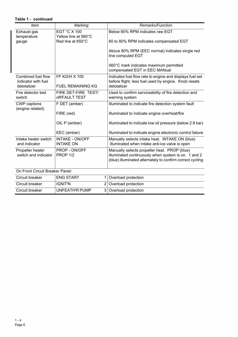
Extega
Co in dFiswCW(e
In aPr sw
OnCiCiCi
Item Marking Remarks/Function
1 - Pag
Table 1 - continued
haust gasmperature uge
EGT LC X 100Yellow line at 560LCRed line at 650LC
Below 60% RPM indicates raw EGT
60 to 80% RPM indicates compensated EGT
Above 80% RPM (EEC normal) indicates single red line computed EGT
560LC mark indicates maximum permitted compensated EGT in EEC MANual
mbined fuel flowdicator with fueletotalizer
FF KG/H X 100
FUEL REMAINING KG
Indicates fuel flow rate to engine and displays fuel set before flight, less fuel used by engine. Knob resets detotalizer
re detector test itch
FIRE DET-FIRE TEST/ off/FAULT TEST
Used to confirm serviceability of fire detection and warning system
P captionsngine related)
F DET (amber)
FIRE (red)
OIL P (amber)
EEC (amber)
Illuminated to indicate fire detection system fault
Illuminated to indicate engine overheat/fire
Illuminated to indicate low oil pressure (below 2Q8 bar)
Illuminated to indicate engine electronic control failuretake heater switchnd indicator
INTAKE - ON/OFFINTAKE ON
Manually selects intake heat. INTAKE ON (blue) illuminated when intake anti-ice valve is open
opeller heateritch and indicator
PROP - ON/OFFPROP 1/2
Manually selects propeller heat. PROP (blue) illuminated continuously when system is on. 1 and 2 (blue) illuminated alternately to confirm correct cycling
Front Circuit Breaker Panel:rcuit breaker ENG START 1 Overload protectionrcuit breaker IGNIT'N cc2 Overload protectionrcuit breaker UNFEATH'R PUMP ccccccccc3 Overload protection
4e 6
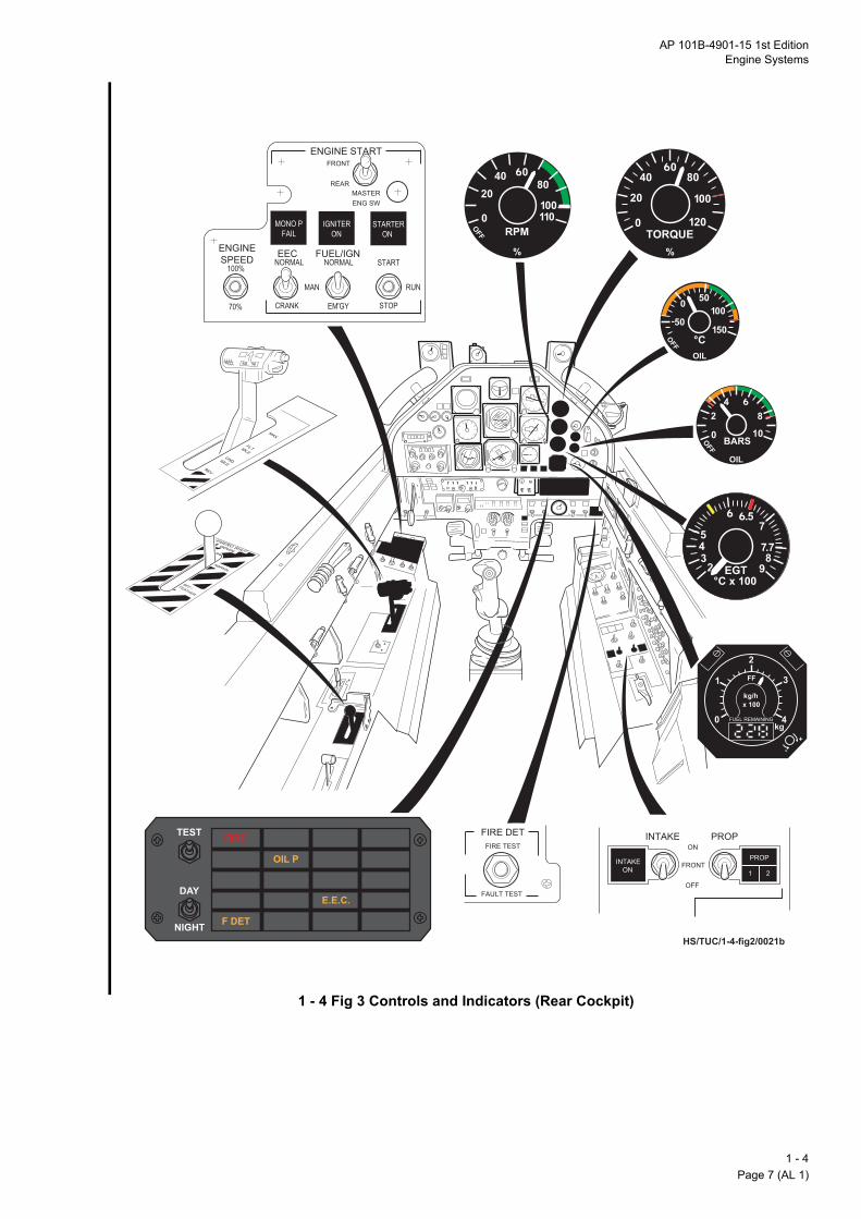
AP 101B-4901-15 1st EditionEngine Systems
Controls and Indicators (Rear Cockpit)
1 - 4 Fig 3 Controls and Indicators (Rear Cockpit)
HS/TUC/1-4-fig2/0021b
FIRE
OIL P
E.E.C.
F DET
TEST
DAY
NIGHT
FRONT
1 - 4Page 7 (AL 1)

Table 2 - Engine Controls and Indicators (Rear Cockpit)
Em le
Th
Sp
En
Fu
St
MindIgStM
RP
To
Oiga
Oi
1 - Pag
Item Marking Remark/Functionsergency shutdown
verEMERG SHUT DOWN- NORMALOFF/FEATHER
NORMAL - Normal runningOFF/FEATHER - Closes FCU fuel shut-valve, disables NTS, actuates feathering valve and fuel purge system
rottle MAX/FLT IDLE/GND IDLE/REVREVerse has red/white hatching
Controls engine power demand and propeller pitch. Abaulk solenoid prevents movement aft of FLT IDLE inflight
eed switch ENGINE SPEED - 100%/70%
Spring-loaded to centre. Selects engine speed:70% ccccccccccc- Ground operation100% ccccccccc- Flight operation
gine mode switch EEC - NORMAL/MAN/CRANKRed cap
Gated in all positions. Selects engine control mode:NORMALccc - Control by EECMAN ccccccccc- Manual controlCRANK ccccc- Engine cranked without fuel and ignition
el/ignition switch FUEL IGN- NORMAL/EM'GY
Spring-loaded to NORMAL. Selects fuel and ignitionsystem control:NORMAL ccc- Control by EECEM'GY cccccc- Manual control
art switch START/RUN/STOP Spring-loaded from START to RUN, gated from RUN to STOP. Controls engine running:
START c- Mode switch NORMAL: initiates start or relight cycle
cc- Mode switch MAN: runs unfeathering ccpump
cc- Mode switch CRANK: must be held cselected for dry crank
RUN c- Normal operation STOPcc - Shuts down engine (may take up to five
seconds) and selects fuel purge systemonopole fail icator
MONO P FAIL (amber) Inoperative
niter indicator IGNITER ON (white) Indicates ignition system onart indicator STARTER ON (amber) Indicates start systems onaster start switch MASTER ENG SW
- FRONT/REARSelects front or rear cockpit start authority
M gauge RPM %Red line at 101%Green sector 70 to 100%
Indicates engine speed
rque gauge TORQUE %Red line at 100%
Indicates engine torque
l temperature uge
LC OILAmber sector -40 to +55LCGreen sector +55 to 110LCAmber sector +110 to 127LCRed line at 127LC
Indicates engine oil temperature
l pressure gauge BARS OILRed lines at 2Q76 and 8Q3 barAmber sector 2Q76 to 4Q83 barGreen sector 4Q83 to 8Q28 bar
Indicates engine oil pressure
4e 8
(Continued)

AP 101B-4901-15 1st EditionEngine Systems
Exhaust gas temperaturegauge
EGT LC X 100Yellow line at 560LCRed line at 650LC
Below 60% RPM indicates raw EGT
60 to 80% RPM indicates compensated EGT
Above 80% RPM (EEC normal) indicated single red line computed EGT
560LC mark indicates maximum permitted compensated EGT in EEC MANual
Combined fuel flowindicator with fuel detotalizer
FF KG/H X 100
FUEL REMAINING KG
Indicates fuel flow rate to engine and displays fuel setbefore flight, less fuel used by engine. Repeater of front cockpit indicator
Fire detector test switch
FIRE DET - FIRE TEST/ off/FAULT TEST
Used to confirm serviceability of fire detection and warning system
CWP captions(engine related)
F DET (amber)
FIRE (red)
OIL P (amber)
EEC (amber)
Illuminated to indicate fire detection system fault
Illuminated to indicate engine overheat/fire
Illuminated to indicate low oil pressure (below 2Q8 bar)
Illuminated to indicate engine electronic control failureIntake heater switch and indicator
INTAKE - ON/FRONT/OFFINTAKE ON
Manually selects intake heat. INTAKE on (blue) illuminated when anti-ice valve is open
Propeller heater switch and indicator
PROP - ON/FRONT/OFFPROP 1/2
Manually selects propeller heat. PROP (blue)illuminated continuously when system is on. 1 and 2(blue) illuminated alternately to confirm correct cycling
Item Marking Remark/FunctionsTable 2 - continued
1 - 4Page 9 (AL 1)

CONTROLS AND INDICATORS
8.in T
Ge
9.wh(FCthelowflowsys
10Tha mauthrbeto
Lo
11witis bsensolen
HP
12pre
Fu
13
14op
15valof (EGto
16moacc
17SP
1 - Pag
The front and rear cockpit controls and indicators for the engine are shown in Fig 2 and Fig 3 and listedable 1 and Table 2 respectively.
ENGINE FUEL SYSTEM
neral
Fuel from the aircraft fuel system (see Chapter 3) is supplied via an engine-driven fuel control assembly,ich comprises a boost pump with integral filter, high pressure (HP) pump and the fuel control unitU)(Fig 4). During normal running the HP pump supplies fuel to nozzles in the combustion chamber via FCU and a flow divider. A separate fuel heater with an anti-icing lockout valve controls fuel heating in outside air temperatures. A primary flow solenoid valve in parallel with the flow divider controls the fuel during starting. During shutdown, after the engine has been run above 95% RPM, a pneumatic purge
tem removes all residual fuel from the fuel manifolds.
. The fuel flow from the FCU is determined by a main metering valve controlled by pneumatic bellows.e pneumatic supply for these bellows is P3 air modified by the EEC. Overspeed protection is provided by
echanical governor in the FCU immediately downstream of the main metering valve. This governortomatically limits the metered fuel when preset overspeed RPM are reached. If the EEC malfunctions, theottle actuates a manual mode valve in the FCU. This valve then modifies P3 air to drive the pneumaticllows such that, at most throttle settings, the fuel flow is reduced and the throttle will need to be advancedrestore power (see para 59).
w Pressure Fuel Supply
. The fuel control assembly boost pump maintains fuel pressure at the HP pump inlet to prevent cavitationhin that pump. A bypass valve is fitted to the filter between the boost and HP pumps and opens if the filterlocked. The fuel is heated by hot engine scavenge oil in an external heater controlled by a temperature-sitive anti-icing valve; this begins to open at 10LC and is fully open by 0LC. During engine start a separate
enoid-operated anti-ice lockout valve prevents fuel recirculating back through this external heater, thussuring that sufficient fuel reaches the FCU.
Fuel Supply
. The gear type HP pump supplies fuel to the FCU. To protect the FCU against excessive pressure, assure relief valve bleeds HP fuel back to the pump inlet.
el Control Unit
. The FCU does all the fuel metering in both NORMAL and MANual modes of the EEC.
. Start Flow. The main metering valve has a minimum flow stop, which is factory preset to provide thetimum fuel for light-up.
. Fuel Enrichment. As the engine accelerates after light-up the EEC signals the FCU enrichment solenoidve to open to augment the normal metered flow, in order to increase the rate of acceleration. Operationthe enrichment valve is intermittent (showing as momentary peaking of the exhaust gas temperatureT)) since it is shut off whenever 695LC (raw EGT) is approached. Enrichment is available for starting up
60% RPM and, on a later variant of EEC, between 60 and 90% RPM to aid acceleration.
. Acceleration Control. During engine acceleration the FCU pneumatic bellows sense the increasingdified P3. This controls the main metering valve to maintain the correct air/fuel ratio throughout theeleration, thus keeping the engine within safe temperature and surge limits.
. Underspeed Governing. The EEC compares the actual engine speed with that selected at the ENGINEEED switch. The underspeed governor (USG) in the EEC removes any discrepancy by adjusting P3 at
4e 10

AP 101B-4901-15 1st EditionEngine Systems
the FCU pneumatic bellows, to increase or decrease the fuel flow to maintain the minimum of 72% or 94%RPM.
18. Throttle Control. With the throttle well aft of FLT IDLE (in the beta range) the USG controls the RPM.However, as the throttle is moved forward towards FLT IDLE, the signal from the throttle positionpotentiometer at some point exceeds the signal from the USG and takes control of the fuel flow. Therefore,the RPM start to increase (from 94%) until the propeller governor comes on speed (100%); then the engineenters the propeller governing mode.
19. Torque Limiting. If the throttle demand tends to exceed 100% torque, the EEC signals the FCUautomatically to reduce the fuel flow.
20. EGT Limiting. If the throttle demand tends to exceed the calculated single red line (SRL) EGT limit of650LC, the EEC signals the FCU automatically to reduce the fuel flow.
21. Overspeed Protection. A mechanical governor, immediately downstream of the main metering valve,provides overspeed protection; it is set at 104 to 105Q5% RPM. This governor also provides the secondarymonopole engine speed signal to the EEC.
Flow Divider
22. The flow divider controls the flow of metered fuel to the nozzles during the start cycle. An externalprimary flow solenoid valve controls the pressure across the flow divider, to ensure that only primary flow isavailable up to a nominal 60% RPM, i.e. during light-up and acceleration to idle speed. Above 60% RPM theflow divider also opens to a secondary manifold to further increase flow from the nozzles.
Manifolds and Nozzles
23. The annular combustion chamber contains ten duplex fuel nozzle assemblies, each fed by the separateprimary and secondary manifolds.
Fuel Purge System
24. The fuel purge system uses bleed air (P3), stored in a pneumatic accumulator, to burn off residual fuelin the nozzle manifolds during shutdown. As the engine runs down a solenoid valve opens to admit this air,via a filter, to the flow divider. This forces the residual fuel to the combustion chamber where it is burned.There is, therefore, a momentary surge in RPM and EGT when STOP is selected before the engine stops.The system is also operated by a microswitch when an EMERGency shut down lever (ESDL) is selected to
OFF/FEATHER. The accumulator starts being charged at 80% RPM, and is fully charged when the enginehas run above 95% RPM. If a start is aborted before the RPM have risen enough to charge the accumulator,the purge system is inoperative; fuel may be dumped through the combined drain on the right of the engineduring the next start.
1 - 4Page 11 (AL 1)

Fuel Control - Schematic
Ign
25higcircignunignis ignshu
Oil
26graflapble
1 - Pag
1 - 4 Fig 4 Fuel Control - Schematic
IGNITION SYSTEM
ition Unit and Igniter Plugs
. The ignition system comprises a common capacitor-discharge unit on the engine oil cooler, and twoh-energy igniters in the combustion chamber. The power supply is from the essential services busbar. Auit breaker labelled IGNIT'N is on the forward circuit breaker panel on the right in the front cockpit. Theiters operate automatically between 10% and 60 to 65% RPM during engine starting, and when relightingder EEC (NORMAL) control. If the engine approaches flame out in flight the NTS system trips an auto-ition switch which switches ignition on. The engine FUEL IGNition switch controls ignition when the EECselected to MANual. When selected to EM'GY, the EEC operates the fuel enrichment solenoid anditers. Additionally, when airborne, it operates the unfeathering pump and signals open the HYD/FUELt-off valve.
OIL SYSTEM
Tank
. The oil system (Fig 5) is self-contained. An oil tank is on the right-hand side of the engine. The tank isvity filled and the contents are indicated on a dipstick attached to the filler cap, which is behind a hinged in the right-hand side of the engine cowl. The oil tank and an accumulator are pressurized using engine
ed air (P3).
4e 12
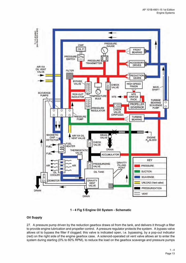
AP 101B-4901-15 1st EditionEngine Systems
Engine Oil System - Schematic
1 - 4 Fig 5 Engine Oil System - Schematic
Oil Supply
27. A pressure pump driven by the reduction gearbox draws oil from the tank, and delivers it through a filterto provide engine lubrication and propeller control. A pressure regulator protects the system. A bypass valveallows oil to bypass the filter if clogged; this valve is indicated open, i.e. bypassing, by a pop-out indicator(red) on the right side of the engine gearbox case. A solenoid-operated oil vent valve allows air to enter thesystem during starting (0% to 60% RPM), to reduce the load on the gearbox scavenge and pressure pumps
1 - 4Page 13

and hence the starter. The accumulator provides circulation to the propeller governor (PG) for a limited timedu
Inv
28forg o
29themawitsys
Oil
30sepde
Oil
31to tanret
Oil
32geblacoocau
Ge
33a fhoanrevsta
34
1 - Pag
ring inverted flight.
erted Oil Supply
. An inverted oil supply accumulator provides a supply of oil to maintain propeller governor operation, and lubrication of the high-speed pinion gear and the rear turbine bearing, for up to 30 seconds during negativeperation. The accumulator is charged by an independent P3 air tapping on the engine casing.
. When positive g is restored the accumulator is recharged with oil. Expelled air and any oil leakage from accumulator are fed back to the oil tank via the pressurizing valve. A drain path allows residual oil, whichy have leaked past the check valve during transient starting or shutdown conditions, to vent via a pipehin the combined drain. Excessive oil around the drain may be indicative of a leak within the inverted oiltem, and should be investigated.
Pressure
. The cockpit gauge indication of oil pressure is generated by a transmitter mounted on the engine. Aarate pressure switch is actuated by oil pressure below 2Q8 bar to illuminate (subject to a 20-second
lay) an OIL P caption on the CWP.
Scavenge
. Three engine-driven scavenge pumps (two in the gearbox and one at the turbine bearing) return the oilhe tank through a fuel heater and oil cooler. There is a magnetic chip detector at the fuel heater inlet. Aird gases mixed with the oil are removed at an oil demister and vented by a drains system, the oil beingurned into the gearbox casing to be scavenged.
Temperature
. The cockpit gauge indication of oil temperature is sensed by a temperature bulb on the rear face of thearbox. As the oil temperature increases towards its normal operating level, oil partially bypasses an airst cooler until a thermostatic bypass valve closes at 71Q1LC, when the full flow of oil passes through theler. Low ambient air temperature at altitude combined with low fuel temperature at the fuel heater mayse the in-flight oil temperature to reduce below the minimum of 55LC (see para 95).
PROPELLER SYSTEM
neral
. A 4-blade, fully feathering, reverse pitch propeller with aluminium blades is driven by the engine through
ixed reduction gearbox. The propeller rotates clockwise as viewed from the cockpit. The propeller hubuses the pitch change mechanism, which uses a feathering spring to move the blades towards feather,d boosted high pressure engine oil (0 to 27Q07 bar) to move the blades from feathered through fully fine toerse pitch. The pitch change mechanism includes start locks, to hold the blades in a fine pitch duringrting.
. The engine operates in two distinct control modes:
a. Beta Mode. During ground operations, with the throttle in the range full REVerse to FLT IDLE, theengine operates in the beta mode. The blade angle is controlled directly by the throttle through thepropeller pitch control (PPC), and the RPM are maintained at the selected value by the fuel meteringUSG (Note that the USG is an electronic function of the EEC; therefore, if the EEC is inoperative thereis no USG functioning).
b. Propeller Governing Mode. With the throttle in the range FLT IDLE to MAXimum the engineoperates in the propeller governing mode. Power is set by the throttle, which controls the fuel flow, andthe propeller governor (PG) maintains the RPM by varying the propeller blade angle.
4e 14

AP 101B-4901-15 1st EditionEngine Systems
Pitch Control
35. In the propeller governing mode (throttle forward of FLT IDLE), the PG controls the flow of boosted highpressure engine oil to the pitch change mechanism. This adjusts the blade angle, so that the aerodynamicload on the propeller equals the engine torque set by the throttle, when the propeller is running at its selectedRPM (100%). In the beta mode (throttle aft of FLT IDLE) the propeller blade angle is set by the throttlethrough the PPC; the USG adjusts the fuel flow to maintain the selected RPM (72% or 94%). In flight a beta-baulk (removed on the ground by a nosewheel weight-on-ground microswitch) prevents the throttle beingmoved aft of FLT IDLE.
36. A feathering valve, connected between the PG and the PPC shuts off the flow of boosted high pressureengine oil from the PG, and oil is then vented from the pitch change mechanism; this allows the featheringspring to move the blades towards feather. This valve is operated either automatically, by the NTS systemwhen the engine flames out, or manually, by the ESDL (Fig 6). The NTS systems allows the featheringspring to move the blades towards feather; when the negative torque has been reduced the oil pressure ventfrom the pitch change mechanism recloses, and further feathering is stopped. The propeller pitch is thus heldin a windmilling state (which creates drag) where oil pressure (reduced because of reduced engine RPM)balances the action of the feathering spring. Therefore, to feather the blades fully the ESDL has to beoperated. A DC unfeathering oil pump, is used during relighting to unfeather the blades so that the enginewindmills. This pump runs when START is selected on the START/RUN/STOP switch on the engine startpanel; a circuit breaker labelled UNFEATH'R PUMP is on the forward circuit breaker panel on the right in thefront cockpit. Propeller System
1 - 4 Fig 6 Propeller System
Start Locks
37. On the ground with the engine stopped, the feathering spring attempts to move the propeller blades tothe feathered position. Therefore, to minimize aerodynamic loads during starting, start locks hold thepropeller in fine pitch. The engine is not to be started with the start locks disengaged. Normally, they areengaged by selecting full REV with the throttle until below 30% RPM during the previous shutdown; thethrottle is then set to GND IDLE. However, if the propeller is in the feathered state before the start, the startlocks are to be engaged using the unfeathering pump; to do this, ensure the throttle is selected to REV, select
1 - 4Page 15

the EEC to MAN and select and hold START until the blades visibly enter a reverse pitch. After start the locksarethe
Ne
38winunaudis
39proRP
40A cWithe
41ST
En
42
43proele
Th
44enby FCberetconpotheaftdisbra
45fric
1 - Pag
released by smoothly easing the throttle into REVerse momentarily, thus removing side loads exerted on locks by the feathering spring and allowing them to move outwards centrifugally.
gative Torque Sensing System
. The primary purpose of the NTS system is to limit the amount of torque that the engine absorbs from admilling propeller. When negative torque is sensed, the pitch of the propeller is increased towards feather
til the negative torque is reduced to an acceptable level (see para 36); the engine igniters are alsotomatically switched on and may remain on for up to 10 minutes after the engine has been relit due to slowsipation of the controlling oil pressure.
. The secondary purpose of the NTS system is to control the rate of propeller unfeathering duringpeller-windmilled engine relights so that the engine does not accelerate too rapidly through the relightM range.
STARTING SYSTEM
. On the ground the engine is cranked by a starter/generator powered from the essential services busbar.ircuit breaker labelled ENG START is on the forward circuit breaker panel on the right in the front cockpit.th engine light-up established, the starter reverts to generator-mode to power the aircraft systems. In flight starter is inhibited by the operation of weight-on-ground switches.
. The operation of the starter/generator in starter-mode, is initiated by the start switch on the ENGINEART panel. During normal starting, control is via the EEC.
MANAGEMENT AND CONTROL
gine Control
. The engine is controlled by varying:
a. Fuel Flow. Fuel flow varies power output.
b. Propeller Pitch. Propeller pitch (blade angle) varies aerodynamic load on the propeller.
. At constant engine RPM the torque produced by the engine is equal to the torque absorbed by thepeller. Fuel flow is normally controlled by the EEC, into which throttle position demands are transmittedctronically, and propeller pitch is varied automatically to control propeller (and engine) RPM.
rottles
. The throttle in the front cockpit (mechanically linked to a similar throttle in the rear cockpit) controlsgine fuel scheduling in both automatic and manual modes. In automatic mode the fuel flow is controlledthe throttle via the EEC, whereas in manual mode the throttle is connected mechanically to the PPC andU. A beta-baulk solenoid, controlled by a microswitch on the nose landing gear leg, prevents the throttleing moved aft of FLT IDLE when in flight. Failure of the nose leg microswitch causes the beta-baulk toract thus allowing the throttle into the beta range in the air. Although the NTS system operates there is asiderable increase in drag followed by drag pulsation as the propeller hunts around an equilibrium
sition. Recovery is immediate when the throttle is moved forward of FLT IDLE. There is a weak detent on rear cockpit throttle lever at the GND IDLE position. If the beta-baulk solenoid fails to retract on the grounder flight, the throttle cannot be moved aft of flight idle. As reverse thrust is then unavailable, the landingtance will increase significantly. Consideration should be given to selecting ESDL to Off/Feather if normalking does not suffice.
. The front cockpit throttle has an adjustable friction damper. The knob is rotated clockwise to increasetion.
4e 16

AP 101B-4901-15 1st EditionEngine Systems
46. Control switches are incorporated in both throttles for rudder trim, airbrake and communications.
Emergency Shutdown Levers
47. The emergency shut down lever (ESDL), labelled NORMAL/ OFF/FEATHER, in the front cockpit, ismechanically linked to a similar lever in the rear cockpit. The ESDL closes the mechanical fuel shut-off valve,disables the NTS system, initiates the fuel purge system and operates the feathering valve to allow thepropeller to feather. The ESDL has a striped black/yellow surround and is protected by a raised guard. Theoperating loads on the ESDL tend to be greater in flight than on the ground. Firm and positive movement ofthe ESDL is necessary to ensure full travel to the OFF/FEATHER position. The ESDL should only be usedto shut down the engine in emergency situations (i.e. as advised in the FRC). If the ESDL is used otherwisewhen on the ground, the rapid spool down time of 10 to 15 seconds traps residual heat within the engine.Consequently, close tolerances between rotating assemblies and their shrouds are reduced. The assembliesand shrouds may come into contact and this results in excessive internal wear or even significant damageon very hot engines which have no cooling air induced.
WARNING 1: Failure to achieve the full OFF/FEATHER position results in engine rundown without thepropeller feathering; this leads to a high rate of descent.
WARNING 2: In the event of an airborne shutdown, failure to operate the ESDL before the FUEL CUT OFFswitch results in engine rundown without the propeller feathering; this leads to a high rate of descent.
Note 1: If a start is cancelled below 60% RPM using the ESDL the starter continues to rotate the engine/propeller at about 15% RPM until STOP is selected.
Note 2: If a start is cancelled below 72% RPM the propeller does not feather since the start locks are stillengaged; above 72% RPM the propeller only feathers if the start locks have been disengaged.
Engine Operation
48. On the ground the engine may be run at less than 100% RPM to reduce propeller and engine noise. AnENGINE SPEED switch, spring-loaded to a central (neutral) position, is on the left console in each cockpit.It is marked 70%/100% and can be used to select the lower RPM. A microswitch, operated by the throttle,is provided to override a 70% selection when the throttle is forward of FLT IDLE, thus any attempt to take-offwith 70% inadvertently selected should not be possible. Table 3 shows the values of RPM selected by theENGINE SPEED switch at the USG and the PG.
Table 3 - RPM Control Values
49. In flight the engine speed is selected to 100%. This selects about 94% on the USG and 100% on thePG. As the throttle is moved the throttle metering valve increases or decreases the fuel flow and the PGincreases or decreases the blade angle to maintain 100% RPM. When airspeed is reduced the blade anglereduces to maintain 100% RPM until a blade angle of +8Q5L is reached. If airspeed is further reduced theblade angle remains at 8Q5L and the RPM begin to decrease. At about 94% RPM the USG begins to increasethe fuel flow to maintain RPM.
50. During the landing roll, providing the weight-on-nosewheel microswitch is made, the throttle can bemoved aft of FLT IDLE towards GND IDLE and the blade angle reduces under the control of the PPC. Asthe blade angle reduces to minus 1L (approximately zero thrust with the aircraft stationary) the USG controlsthe fuel flow to maintain about 94% RPM. Further rearward movement of the throttle moves the blade angleto minus 2L and the USG now increases the fuel flow to maintain about 94% RPM with the engine producingreverse thrust.
Engine Speed Switch Setting
UnderspeedGovernor
PropellerGovernor
70% *72 to 73% 96%100% 94% 100%
* 80% when air conditioning BOOST selected.
1 - 4Page 17

51. For ground operations the engine speed is normally selected to 70%. This resets the USG datum toabthe
En
52anis r
53
54
55po10to thu
56
1 - Pag
out 72Q5% and the PG datum to 96%. The engine operates as in para 50 but with the USG maintaining engine RPM at 72Q5% and not 94%.
gine Electronic Controller
. The EEC measures various engine parameters (see para 54) and uses them to control engine fuel flowd propeller blade pitch and thus engine power output. It is powered from the essential services busbar andemote from the engine. Its functions are:
a. Controlling automatic starting.
b. Scheduling acceleration fuel.
c. Controlling fuel metering.
d. Limiting positive engine torque.
e. Limiting EGT.
f. Correcting single red line (SRL) EGT.
. There are potentiometers on the EEC to allow maintenance personnel to adjust:
a. Maximum RPM.
b. Idling RPM.
c. Flight idle fuel flow.
d. SRL EGT.
e. Maximum torque.
. The EEC (selected to NORMAL) provides control signals to the FCU (Fig 7) which are based on:
a. Throttle position.
b. Engine speed (% RPM).
c. Compressor inlet temperature (T2).
d. Turbine outlet temperature (T5).
e. Engine pressure ratio (DP2/P5).
f. Engine torque (%).
. In propeller governing mode, moving the throttle forward signals a request to the EEC for an increase inwer. The EEC signals the FCU to increase fuel flow. The increased fuel flow tries to increase RPM past0%, but this tentative RPM increase is sensed by the EEC which signals the PG to decrease oil pressurethe PPC. This allows the propeller pitch to coarsen and thus increase the load on the propeller. RPM iss still limited to 100% and the power output is increased as shown on the torque gauge.
. The following situations automatically switch the EEC to MANual:
a. Failure of supply voltage to the EEC.
b. Failure of throttle lever signal.
4e 18

AP 101B-4901-15 1st EditionEngine Systems
c. Mismatch between the throttle lever signal and the signal at the FCU.
d. Failure of a monopole sensor above 55% RPM.
CAUTION: Should the EEC trip to MANual, especially at high power selections, there is a risk that the manuallimit for EGT (560LC) will be rapidly exceeded. Therefore, in the event of an automatic trip to MANual, powerdemand should be reduced promptly.
57. When the EEC is operating normally, selection of the EEC to MANual mode and reversion to NORMALmode is permitted as required. Torque is to be at 30% or below when selecting EEC NORMAL to MANualand 20% or below when selecting EEC MANual to NORMAL. After reversion to NORMAL confirm that EGTis at or below 650LC.
CAUTION: The throttle is not to be moved aft of GND IDLE when in MANual mode because fuel metering bythe USG is not available. Serious damage to the engine may occur if this limitation is not observed.
Manual Engine Control
58. When the EEC fails and/or is switched to MANual (indicated by the EEC caption being illuminated on theCWP), the fuel flow is controlled by a mechanical linkage between the throttle and the FCU. The followingfunctions are lost:
a. Automatic starting.
b. Acceleration fuel.
c. Torque limiting.
d. SRL EGT limiting.
e. Engine speed selection (reverts to 100%).
f. USG fuel control.
59. For most throttle positions forward of GND IDLE, but short of MAXimum power, the MANual mode givesabout 15 to 20% less fuel than the NORMAL mode. Therefore, higher throttle positions are necessary toachieve the required power in MANual mode. However, at or near MAXimum power settings, under certainambient conditions, fuel flow may be increased in MANual mode, potentially resulting in a temperature
exceedance. To reduce the likelihood of an exceedance, an EGT limit of 560LC is imposed in MANual mode.The nominal engine performance in MANual mode is determined by a P3 air signal to the FCU that isinfluenced by several factors, including:
a. Throttle lever setting.
b. Flight"ambient conditions.
c. Variations in efficiency from engine-to-engine.
d. Variations from FCU-to-FCU due to tolerances.
Note 1: If more engine power should be needed at any stage, a change of AIR COND selection from BOOSTto NORMal (or to BLEED air OFF"RESET) will reduce air bleed and hence increase torque.
Note 2: Automatic limiter functions are not available in MANual mode. EGT and torque limiting are controlledby the throttle lever.
Monopole Sensors
60. Two independent monopole sensors (magnetic speed pick-ups) feed engine speed information to theEEC. The primary monopole is in the propeller governor and the secondary monopole is within the FCU. If
1 - 4Page 19 (AL 1)

either monopole sensor fails, the EEC will automatically switch to MANual mode and the CWP EEC captionwil
EG
61tementemthecomsel
To
62disbe
1 - Pag
l illuminate.
T Indications
. Eight thermocouples measure raw turbine outlet temperature (T5). A compensator corrects the rawperature for engine manufacturing tolerances and compensated EGT is passed to the EEC. Changes to
gine RPM, T2 and the engine pressure ratio change the relationship between T5 and turbine inletperature (T4). Using these variables the EEC converts compensated EGT to calculated EGT. Provided
calculated EGT does not exceed 650LC, T4 remains below the permitted maximum. Calculated EGT ismonly referred to as SRL EGT. The type of EGT shown on the EGT gauge varies with RPM and EEC
ection:
a. Raw EGT. 0 to 60% RPM.
b. Compensated EGT.
(1) Ground running below 80% RPM.
(2) All conditions with EEC manual and in excess of 80% RPM.
c. SRL EGT. All conditions with EEC normal and in excess of 80% RPM.
rque Indications
. Engine torque is calculated from a signal derived from a strain gauge bridge in the engine gearbox andplayed on the torque (%) gauge. Positive torque is indicated between zero and 120 and negative torquelow zero. Torque information is also fed to the EEC.
4e 20

AP 101B-4901-15 1st EditionEngine Systems
Engine Power Management System
1 - 4 Fig 7 Engine Power Management System
1 - 4Page 21

NORMAL OPERATION
En
63buEleNOstaST
Nothe
64to indby
65onIGNap
66
67bethastacyc
68swcanprothe
1 - Pag
gine Starting
. Turn the propeller through 90L by hand. Select GEN to ON/RESET. Test the batteries and essentialsbar; if necessary, connect an external engine-driven ground power unit DC supply or Trolley Batteryctrical Starter (TBES). Set the MASTER ENGine SWitch to FRONT or REAR as required, the ESDL toRMAL, the EEC switch to NORMAL, and the ENGINE SPEED switch momentarily to 70% (to set the afterrting idle speed). Ensure that the propeller start locks are engaged (see para 37), set the start switch atOP and the throttle at GND IDLE.
te: If the EGT is higher than 200LC, dry crank the engine (see para 69), observing starter limitations, until temperature is below 200LC.
. Initiate the start cycle by selecting the relevant start switch to RUN and holding it against spring pressureSTART for 2 seconds. Simultaneously, start the stopwatch and note the illumination of the STARTER ONicator light. At 10% RPM, the start fuel cycle commences and the igniter plugs are energized as indicatedthe IGNITER ON indicator light; light-up occurs within 5 seconds (10 seconds after a cold soak).
. Monitor the RPM and EGT, check that the oil pressure is rising and observe the EEC and FIRE captions the CWP. If the light-up is successful, the igniter plugs and starter de-energize at 60 to 65% RPM and the
ITER ON and STARTER ON indicator lights go out. The engine accelerates to the ground idle speed ofproximately 72% (with air conditioning BLEED set to OFF/RESET) under the control of the EEC.
. Abort the start (see para 68) if any of the following occur:
a. The propeller does not turn when START is selected.
b. There is any unusual noise or vibration.
c. The RPM fail to reach 5% within 10 seconds of START selection.
d. The engine does not light up (EGT rising) within 5 seconds (10 seconds after a cold soak) of theIGNITER ON indicator light illuminating.
e. The EGT rises rapidly through 730LC or is likely to exceed 770LC.
f. The RPM fail to reach 30% within 35 seconds or stagnate during any part of the start cycle.
g. The oil pressure does not rise or the OIL P caption does not go out within 10 seconds of reaching60% RPM.
h. The STARTER ON and IGNITER ON lights do not extinguish at 60 to 65% RPM or within 60seconds of selecting START.
i. The CWP EEC or FIRE captions illuminate.
. Starter Limitations. If the starter is inadvertently disengaged, allow the propeller to stop completelyfore making another attempt. A maximum of 3 start/dry crank cycles may be attempted (each no longern 60 seconds) at 2-minute intervals. A period of 15 minutes must then elapse before attempting furtherrts using the same sequence. Only 3 start cycles may be made using internal batteries; before each startle the battery voltage must be above the minimum for engine starting.
. Aborting the Start. If it is necessary to abort the start, select the ESDL to OFF/FEATHER and the startitch to STOP. This shuts off the fuel flow and de-energizes the starter and the igniter plugs. If a start iscelled using only the STOP selection, fuel shut off may take up to 5 seconds. Below 72% RPM thepeller does not feather as the start locks are still engaged; above 72% RPM the propeller only feathers if start locks have been disengaged.
4e 22

AP 101B-4901-15 1st EditionEngine Systems
Note: The fuel purge system is inoperative when a ground start is aborted. The associated accumulator isnot recharged unless RPM exceed 95% during an engine running cycle. Fuel may be dumped through thecombined drain on the right of the engine during the next start cycle.
69. Dry Crank. Following a failed start attempt, carry out a dry crank before a further start to reduce the EGTto below 200LC or to ventilate the engine of unburnt fuel. To dry crank the engine, select the EEC to CRANKthen select the start switch to START for the required period (no longer than 30 seconds). The RPM rise tostabilize at 13 to 15%. When the dry crank is complete, select the start switch to STOP, the EEC to NORMALand the ENGINE SPEED switch momentarily to 70%. Wait 2 minutes for the starter to cool before making afurther start attempt.
70. Start Cycle Cooling. If the start is cancelled at less than 60% RPM using only the ESDL, the starterwill continue to rotate the engine at about 15% RPM until STOP is selected. Use the starter in this way to coolthe engine and obviate the requirement for a dry crank. To cool the engine during the start cycle:
a. Abort the start by selecting the ESDL to OFF/FEATHER.
b. Ensure that the EGT stops increasing and fuel flow reduces to zero.
c. Monitor the EGT and the clock. Select STOP when the EGT reduces to less than 200LC or the clockreaches 60 seconds, whichever is the sooner.
d. If the EGT remains above 200LC after 60 seconds, carry out a separate dry crank. Otherwise,attempt a further start, observing the starter limitations (see para 67).
After Starting
71. After starting, with the throttle at GND IDLE, check that RPM are 72 to 73% and EGT is below 560LC.Set both MAIN FUEL PUMPS to ON and check that all CWP captions are out. Smoothly ease the throttleinto REVerse momentarily to release the propeller start locks.
Take-Off
72. Before take-off select the ENGINE SPEED switch to 100%. When lined up select 20% torque and ensurethat RPM are 100m1%, EGT is increasing, oil temperature and pressure indicate in the green sectors. Whenfull power is selected, torque rises quickly; the maximum permitted torque is 100% with a maximumoverswing of 115%. RPM may reach a transient maximum of 101-104% for up to 30 seconds. The EGT, risingmore slowly than the torque, may overswing to a maximum of 660LC for 5 seconds, before settling at the red
line maximum of 650LC.
Note: Depending on conditions, the EEC will limit the engine output either at 100% torque or at 650LC EGT.The engine is serviceable if either torque or EGT is at its limit.
In Flight
73. Refer to Part 3, Chapter 2 for detailed information on engine handling in flight.
After Flight
74. Do not use REVerse thrust if the EEC is in MANual mode.
75. After decelerating to taxying speed select 70% momentarily. After being at low power for 3 minutes(including approach, landing and taxying) set the throttle to REV (in EEC NORMAL mode only) to engage thestart locks then select the start switch to STOP.
CAUTION: Reselecting RUN after an inadvertent STOP selection but before the propeller has stoppedrotating may result in damage to the engine.
1 - 4Page 23

USE IN ABNORMAL CONDITIONS
En
76
En
77aninsthesenor is a
78con(10ProIf R
79thephfunmadraCrufligfau
RP
80capresthetrapoha
81
EnFCAnInPr
1 - Pag
gine Fire
. If the CWP FIRE caption illuminates, carry out the FRC Engine Fire or Engine Fire on the Ground drill.
gine Malfunction Diagnosis
. Engine power management and control relies on the integrity of the engine and propeller, accessory andcillary components, as well as their supporting systems and the services provided by the aircrafttallation (as illustrated in Fig 4 to Fig 7 inclusive). Engine and engine control malfunctions may arise from failure of any element within these systems. In conjunction with operating conditions, other indications,sory cues and cautionary warnings, engine malfunctions may be characterised by whether RPM is stable
reducing. RPM is an essential tool in the diagnosis of engine (and engine control) malfunctions. If thereny abnormal engine control response or indication, with or without an EEC caption, check the RPM.
. It is important to understand the behaviour of the RPM. 4Reducing4 means that the RPM reducetinuously, when the engine should be shut down. 4Stable4 means that the RPM either remain at normal0 m 1%) or stabilise at a value below normal, having reduced from normal almost instantaneously.vided that RPM remain stable and the engine continues to provide useful thrust, it need not be shut down.PM cannot be maintained above 85% the engine may have to be shutdown.
. Automatic reversion of the EEC to MANual and failures of the EGT and torque sensing components of engine control system are relatively common. Automatic reversion to MANual mode can occur at any
ase of flight and is a design characteristic response when the EEC cannot fulfil its control or monitoringction (see para 56). In such cases the EEC caption will illuminate, however other control systemlfunctions may not illuminate an EEC caption. Symptoms may include a significant loss of thrust or highg (depending on throttle setting), a change in engine note and no response to throttle movement.cially, the RPM remain stable. Although these failures can be alarming, especially at a critical phase of
ht, they can usually be remedied by selecting EEC to MANual. Table 4 below summarises known enginelts.
Table 4 - Engine Faults
RPM Stable RPM Reducinggine Control Malfunction See para 80 Bogdown See para 85U Failures See para 81 Flameout See para 88cillary Component Failure See para 82 Mechanical Failure See para 91
dication Fault See para 83 Inadvertent ESDL See para 92opeller Malfunctions See para 84
M Stable
. Engine Control Malfunction. If there is any abnormal response or indication, with or without an EECtion with RPM stable, set 30y torque if practicable a or throttle to mid9quadrant if the torque does notpond to throttle movement or torque gauge is unreliable a and switch the EEC to MANual mode. Advance throttle to restore power but do not allow the EGT to exceed 560LC in manual mode a about 2"3 throttlevel if the EGT gauge does not respond to throttle movement. If the abnormal symptoms disappear andwer is restored, do not reselect EEC to NORMAL. Refer to Part 3, Chap 2 for information on enginendling in manual mode.
. FCU Failures.
a. Bellows Failure. Following on from para 80, if after selecting EEC to MANual, abnormal symptomspersist (torque, EGT and fuel flow decaying with normal RPM) and full throttle fails to restore power, afailure may have occurred within the FCU bellows assembly (see Part 1, Chap 4, Fig 4). Fuel supply tothe engine may have decreased, and may continue to decrease, resulting in a progressive reduction inmaximum available torque. Once the torque has reduced to zero, a further decrease in fuel supply willresult in a reduction in RPM. The timescale over which this process occurs will depend on the severity
4e 24

AP 101B-4901-15 1st EditionEngine Systems
of the failure but, in the extreme case, is a matter of seconds. The fuel supply to the engine can beaugmented by holding the FUEL"IGN switch to EM4GY and using start fuel enrichment to increaseavailable torque by 10 to 20%, depending on altitude. However, this is only effective while there issufficient fuel flow available; once the fuel flow has decreased beyond a certain point, holding theFUEL"IGN switch to EM4GY will have no effect. When RPM starts to reduce the engine should be shutdown using the FRC Engine Shutdown drill.
Note: Selecting the FUEL"IGN switch to EM4GY also runs the unfeathering pump. The pump motor isnot continuously rated and may fail or catch fire if run continuously; for this reason, pull C"B 3(UNFEATHR PUM4P) when time permits. Selecting AIR COND BLEED OFF"RESET and INTAKE iceprotection OFF will also augment maximum available torque (see Note Chap 4, Page 19).
b. Torque Motor Failure. A rare failure within the torque motor flapper valve can cause a sudden fallin P3 air pressure within the bellows assembly (see Chap 4, Fig 4.). This results in a sudden loss ofthrust, accompanied by high propeller drag, low EGT (circa 350LC) and reduced but stable RPM. Settingthe throttle to mid quadrant and the EEC switch to MANual will quickly restore the engine to 100% RPM.
82. Ancillary Component Failure. The maximum output of the engine is controlled by the EEC to either100y torque or 650LC SRL EGT (see paras 19 and 20). An open circuit in the thermocouple ring or EGTharness or breakdown in the EGT Compensator results in a zero9volts signal giving a full9scale EGT readingof 900LC. Similarly, a failure of the torque signal conditioner may result in a maximum torque indication. TheEEC reacts to these false maximum signals by decreasing the fuel flow; power reduces suddenly and cannotbe restored even at full throttle. As the EEC itself may not be at fault and none of the four parameters givenin para 56 are met, the EEC continues to function (no EEC caption) and the RPM remain normal. To restorepower, set 30% torque if practicable a or throttle to mid quadrant if torque does not respond to throttlemovement a and switch the EEC to MANual mode.
Note: A genuine EGT of 900LC in the case above would indicate catastrophic damage to the engine. If theengine is still producing thrust with the RPM at normal, it is likely that the 900LC EGT indication is false.
83. Indication Fault. An EGT or torque gauge fault may result in a fluctuating indication without any changein engine response. A faulty gauge is likely to fluctuate in isolation, without sympathetic fluctuation of anyother gauge. Set 30% torque if practicable a or throttle to mid9quadrant if the torque does not respond tothrottle movement a and switch the EEC to MANual mode. Monitor the indication and land as soon aspracticable; do not reselect the EEC to NORMAL.
84. Propeller Malfunctions. A rare malfunction may cause the propeller to move towards a coarser or finerblade angle than normally scheduled. This will result in a correspondingly lower or higher RPM than the
normal 100% m 1%. If sufficient RPM or power cannot be maintained or the EGT maintained within limits, theengine is to be shut down. Selection of EEC MANual will not resolve the malfunction.
RPM Reducing
85. Bogdown. During flight at less than +0.5g, oil is supplied to the propeller pitch change mechanism bythe oil accumulator which has a limited capacity. Once this supply is exhausted, propeller pitch control is lostand the propeller blades move towards the feathered position under the action of the feathering spring. Thiscauses a very large increase in rotational drag, a reduction in RPM and a rapid increase in EGT. Thecondition is colloquially known as bogdown. The symptoms are:
a. A change in engine note.
b. RPM reducing.
c. Torque reducing.
d. High EGT.
86. If bogdown occurs with full power selected, an overtemperature is inevitable. If it occurs at low powersettings, prompt action may prevent an overtemperature. If a bogdown is identified, apply positive g as soon
1 - 4Page 25

as possible and set the throttle to FLT IDLE. If the EGT limit has been exceeded, land as soon as possibleusi
87invsymen
Fla
88intaoccmaminouIf R
In-
89relunsucspewhincwil
90speCUthe
Me
91canFa
1 - Pag
ng minimum power (ideally from a precautionary forced landing).
. The most common causes of bogdown are the cumulative effect of a series of aerobatic manoeuvresolving less than +0.5g or a single, seemingly innocuous manoeuvre such as a prolonged bunt. Theptoms disappear as soon as oil pressure is restored but, if the EGT limit has been exceeded, serious
gine damage is likely to have occurred.
me Out (and In-Flight Relighting)
. A flame out is most likely to occur as a result of fuel starvation or a disruption in airflow through the engineke (icing or bird strike). The NTS provides an automatic and immediate relight capability. If a flame outurs due to a momentary interruption of fuel or airflow, and the immediate relight is successful, the piloty have no indication that this has occurred other than the ignition light which may remain on for up to 10utes. However, the ignition is also activated if the NTS system operates for reasons other than a flame
t. If the engine does not respond and return to normal the symptoms are RPM, Torque and EGT reducing.PM falls below 80% after a flame out, shut down the engine. Carry out the FRC Flame Out/Relight drills.
Flight Relighting
. The engine starter is inhibited in flight. If the NTS system fails to provide an immediate and automaticight when a flame out occurs the engine should be shut down. A relight can then only be accomplished byfeathering the propeller using the unfeathering pump and windmilling the engine. The chance of acessful relight is reduced if the oil temperature is below l4LC. Since the rate of descent at optimum glideed is only 900 feet per minute, there is usually plenty of time to carry out the drill methodically. However,
en START is selected to unfeather the propeller and the engine begins to windmill, there is a significantrease in drag and a consequent reduction in gliding performance. Although the engine relights quickly, itl not produce usable power until the RPM reach 100%.
. The relights are equally reliable under EEC NORMAL or MANual control. Below 20,000 feet and with theed at 115 to 200 knots, set the throttle at mid-quadrant, confirm the ESDL is at NORMAL and the FUELT OFF is selected OPEN. Switch at least one fuel pump ON, ensuring that the contents are sufficient for selected pump(s). Set the GENerator switch to ON/RESET.
a. EEC NORMAL Relight. With the EEC switch at NORMAL, select the start switch to STOP and thenback to RUN (the EEC caption is illuminated at this stage). Select the start switch to START for 2seconds; this runs the unfeathering pump and the engine starts to rotate. The propeller unfeathers at arate controlled by the NTS system such that acceleration is smooth. Relight is automatic under thecontrol of the EEC; at 10% RPM, the start fuel cycle commences and the igniter plugs are energized asindicated by the IGNITER ON light. The EEC caption should extinguish after selecting START; if it doesnot, or if the propeller fails to rotate, or if the EGT fails to rise within 20 seconds, or if it is likely to exceed770LC, abort the relight by selecting the ESDL to OFF"FEATHER. Attempt a relight with the EEC in
MANual. Operational experience has shown that a normal relight could take up to 2500ft.
b. EEC MANual Relight. If an attempt to relight with the EEC in NORMAL is unsuccessful, or if theEEC had previously failed, perform a relight with the EEC switch set to MANual. Ensure that the ESDLis NORMAL and select START to run the unfeathering pump and windmill the propeller. Ignition is notautomatic; at 10% RPM hold the FUEL"IGN switch to EMGY for 2 seconds. If the subsequent start isslow or stagnates with a low EGT, select the FUEL"IGN switch to EM4GY for one second at a time toaccelerate the start. Abort the relight by selecting the ESDL to OFF/FEATHER if the EGT is likely toexceed 770LC. Do not select the EEC to NORMAL once the engine has relit.
CAUTION: Engine damage will occur if allowed to windmill in the range of 18% to 28% RPM.
chanical Failure
. The symptoms of mechanical failure may include noise, vibration and rapid RPM wind down; if the RPMnot be maintained above 85% the engine should be shut down using the FRC Engine Mechanical
ilure drill.
4e 26

AP 101B-4901-15 1st EditionEngine Systems
Inadvertent ESDL Operation
92. If the ESDL is operated inadvertently, return the lever to NORMAL immediately, set the throttle to mid-quadrant and select the FUEL/IGN switch to EM'GY for 2 seconds. The engine will relight and accelerateunder the control of the NTS system. However, if the lever has been moved fully aft, engine wind down isvery rapid (about 4 seconds). If RPM have reduced to below about 30%, the engine may not relight and/orthe EGT may increase towards the limit of 770LC. Set the ESDL to OFF/FEATHER and consider a relight,forced landing or ejection.
Note: The FUEL/IGN switch in the rear cockpit is inoperative if the MASTER ENGine SWitch is selected toFRONT.
Abnormal Oil Pressure
93. Abnormal oil pressure is indicated on the oil pressure gauge and PO by illumination of the OIL P captionon the CWP. If, during stable level flight, the oil pressure fluctuates, or rises above or falls below permittedlevels (see Part 2, Chap 2, Table 2), reduce power to the minimum required for safe flight, avoid negative g,monitor oil temperature and land as soon as possible. If propeller pitch control is lost, carry out the FRCEmergency Engine Shutdown drill.
Abnormal Oil Temperature
94. High Oil Temperature. If the oil temperature exceeds 110LC but is less than 127LC (high amber),reduce torque to less than 70% and land as soon as possible. The time with temperature above 110LC mustnot exceed 5 minutes. If the oil temperature exceeds 127LC (above the high amber), reduce torque to theminimum practicable, monitor the engine instruments and land as soon as possible.
Note: Engine operation at oil temperature above 150LC may result in loss of oil pressure and propeller pitchcontrol. If propeller pitch control is lost, carry out the FRC Emergency Engine Shutdown drill.
95. Low Oil Temperature. If during flight, the oil temperature decreases to below 55LC (below the greensector), avoid high power settings and land as soon as practicable.
96. Icing Conditions. Monitor oil temperature closely during flight in icing conditions. If increases of 3L to5LC per minute are observed, assume that the engine oil cooler is partially blocked by ice.
In-Flight Shutdown
97. To shut down the engine in flight, select the ESDL to OFF/FEATHER. If time and circumstances permit,and if the engine is unlikely to be relit, carry out the FRC Emergency Engine Shutdown drill. The operatingloads on the ESDL tend to be higher in flight than on the ground; firm and positive movement is necessaryto ensure full travel to the OFF/FEATHER position. Failure to achieve full travel results in engine rundownwithout the propeller feathering, which causes a high rate of descent. The ESDL must be operated beforethe FUEL CUT OFF is selected.
Monopole Failure
98. If either monopole sensor fails, the EEC will automatically switch to MANual mode, and the CWP captionwill illuminate.
Propeller Blade Separation
WARNING: If pre-flight inspection reveals contamination of the propeller hub or rear of the blades withgrease or oil or if, in flight, there is a sudden or abnormal propeller vibration, there is a possibility of imminentfailure of a propeller blade or blade retention component. Blade separation in flight will result in loss of theaircraft.
99. If, in flight, there is abnormal propeller vibration, regain straight and level flight as soon as possible andrecover to the nearest suitable airfield at low speed and power. Keep manoeuvres gentle and to a minimumand fly with a minimum of sideslip. Do not use propeller reverse braking on landing.
1 - 4Page 27 (AL 1)

1 - Pag
Intentionally Blank
4e 28

AP 101B-4901-15 1st EditionHydraulic Power Supplies
PART 1
CHAPTER 5 - HYDRAULIC POWER SUPPLIES
ContentsPara
Illustrations Fig
INTRODUCTION
1. The hydraulic power system comprises a reservoir, motorized shut-off valve, engine-driven pump, high
INTRODUCTION
DESCRIPTIONReservoir … … … … … … … … 2Accumulator … … … … … … … … 3Hydraulic Pump … … … … … … … 5Hand Pump … … … … … … … … 6High Pressure Relief Valve … … … … … … 7Filters … … … … … … … … … 8Pressure Switches … … … … … … … 11Temperature Sensor … … … … … … … 12Controls and Indications … … … … … … 13
NORMAL USEBefore Flight … … … … … … … … 16In Flight… … … … … … … … … 17After Flight … … … … … … … … 18
USE IN ABNORMAL CONDITIONSGeneral… … … … … … … … … 19Hydraulic Failures … … … … … … … 20
Equipment Location … … … … … … … 1Hydraulic Power - Schematic … … … … … 2Controls and Indicators … … … … … … 3
pressure relief valve, pressure switches, temperature sensor, pressure and return line filters (see Fig 2).Hydraulic pressure is maintained at 217 to 220Q4 bar to operate the landing gear and airbrake. An emergencyaccumulator (charged from the main system) provides for emergency lowering of the landing gear. A panelto enable opening and closing the landing gear doors for maintenance is at the rear of the baggagecompartment.
DESCRIPTION
Reservoir
2. The reservoir is charged with nitrogen and hydraulic fluid at a maintenance panel in the baggagecompartment (see Fig 1). The nitrogen pressure gauge is adjacent to the charging connection on themaintenance panel. The fluid contents direct reading gauge is behind the HYDRAULIC RESERVOIR FLUIDLEVEL access panel.
Accumulator
3. The landing gear emergency accumulator is charged with nitrogen to 125Q69 m 1Q38 bar at 15LC(accumulator empty). The EMERGENCY ACCUMULATOR PRE CHARGE maintenance panel, aft of thebaggage door, gives access to a nitrogen charging connection, pressure gauge and a hydraulic pressurerelease valve.
1 - 5Page 1

4. When the aircraft is on the ground (weight switches operated) and main system pressure is above 158Q6baemto illu
Hy
5.gepre
Ha
6.linesto
Hig
7.preshu
Fil
8.Thind
9.tellop
10
Pre
11HYswprethe
Te
12temis f
Co
13swvalEM
14als
1 - Pag
r, the main system pressure switch operates, opening the emergency shut-off valve thus allowing theergency accumulator to be charged. The shut-off valve closes during take-off (via weight switch control)retain emergency accumulator pressure. If the shut-off valve fails to close the EMER HYD caption isminated through the weight switches.
draulic Pump
System pressure is generated by a variable displacement pressure compensated pump on the enginearbox accessory drive. With no service operating, the pump delivers fluid at a continuously monitoredssure of 217 to 220Q4 bar.
nd Pump
A hand pump in the hydraulic bay is permanently connected across the pump suction and high pressures for maintenance operations. The pump is operated from the baggage compartment and the handlewage is adjacent to the pump.
h Pressure Relief Valve
If the system pressure reaches 244.8 m 6Q9 bar a high pressure relief valve opens, reducing systemssure to 51Q7 m 3Q5 bar. The relief valve does not reset until pressure reduces to 13Q8 m 3Q5 bar at enginetdown.
ters
Delivery fluid from the pump passes through a high pressure line filter before distribution to the services.e filter has a 5-micron element but no bypass facility. Incorporated in the filter is a differential pressureicator with a tell-tale button. The button pops out when a differential pressure of 3Q8 bar is exceeded.
A return line low pressure filter (5-micron) has a bypass facility and a differential pressure indicator. A-tale button pops out when a differential pressure of 3Q8 bar is exceeded and the bypass becomeserational at 4Q5 bar.
. Filter tell-tale button locations are shown in Fig 1.
ssure Switches
. Pressure switches in the main and emergency pressure lines illuminate respectively the HYD and EMERD captions on the CWP in each cockpit when pressure falls below 158Q6 bar. The power supply for theitches is from the essential services busbar. When main hydraulic pressure is above 158Q6 bar thessure switch signals the landing gear emergency accumulator charging shut-off valve to open, however,
valve only opens on the ground.
mperature Sensor
. A temperature sensor in the return line also illuminates the HYDraulic warning on the CWP if fluidperature exceeds 107LC. The sensor resets on decreasing temperature at 96LC. The electrical supply
rom the essential services busbar.
ntrols and Indications
. A gated hydraulic shut-off valve switch (HYD - CUT OFF/NORMAL) is in each cockpit. Moving eitheritch to CUT OFF closes the hydraulic shut-off valve. Moving the switch to NORMAL does not reopen theve. With the switch at NORMAL, the valve is signalled to open by selecting the fuel ignition switch to4GY or by selecting the start switch to START.
. The hydraulic shut-off valve is also closed when the FUEL CUT OFF switch is selected to CLOSE (seeo Chap 3).
5e 2

AP 101B-4901-15 1st EditionHydraulic Power Supplies
15. Hydraulic warning captions HYD and EMER HYD on the central warning panel indicate the followingconditions:
a. HYD
(1) Pressure in the main system is below 158Q6 bar or,
(2) Fluid temperature is above 107LC.
b. EMER HYD
(1) Pressure in the emergency system is below 158Q6 bar or,
(2) The emergency shut-off valve has failed to close after take-off.
Table 1 - Controls and Indicators
Control/Indicator Marking Location FunctionHydraulic cut-off switch
HYD - CUT OFF/NORMAL
Main instrumentpanel, bottom left,both cockpits
Closes the shut-off valve to the engine-driven pump
Fuel and hydrauliccut-off switch
FUELCUT OFF
Main instrumentpanel, right,front cockpit
Closes the fuel and hydraulic shut-off valves
Fuel and hydrauliccut-off switch
FUEL CUT OFF - CLOSE/FRONT/OPEN
Main instrumentpanel, right,rear cockpit
CLOSE - closes the fuel and hydraulic shut-off valvesFRONT - transfers controls to front cockpitOPEN - overrides the front cockpit selection and selects the valves open when START is selected
Hydraulic indication
HYD CWP, main instrument panel, bottom right, both cockpits
Illuminated when normal hydraulic pressure is below 158Q6 bar or fluid temperature is above 107LC
Emergency EMER HYD Illuminated when emergency hydraulic pressure
hydraulicindication
is below 158Q6 bar or if the emergency shut-off valve has failed to close after take-off
Warning light(amber)
FUEL OFF Main instrument panel, right, both cockpits
Illuminates when fuel and hydraulic valves have closed and CLOSE is selected
1 - 5Page 3

Equipment Location
1 - Pag
1 - 5 Fig 1 Equipment Location
5e 4

AP 101B-4901-15 1st EditionHydraulic Power Supplies
1 - 5Page 5
Hydraulic Power - Schematic
1 - 5 Fig 2 Hydraulic Power - Schematic

Intentionally Blank
1 - 5Page 6

AP 101B-4901-15 1st EditionHydraulic Power Supplies
Controls and Indicators
1 - 5 Fig 3 Controls and Indicators
HYDEMERHYD
TEST
DAY
NIGHT HS/TUC/1-5-fig3/0022
1 - 5Page 7

NORMAL USE
Be
16Preconche
In
17
Aft
18
Ge
19
Hy
20HYLDWh
21levno
1 - Pag
fore Flight
. Ensure the rear cockpit FUEL CUT OFF switch is to FRONT during the Cockpit checks and, during the-Start checks, that the front cockpit switch has the cover down. During the Cockpit and Pre-Start checksfirm that the HYD CUT OFF switches in the rear and front cockpits are to NORMAL. After engine startck that the HYD and EMER HYD captions are out.
Flight
. The HYD and EMER HYD captions remain out in normal conditions.
er Flight
. During engine shutdown the HYD caption is illuminated but the EMERG HYD caption remains out.
USE IN ABNORMAL CONDITIONS
neral
. In all cases of hydraulic system failure, land as soon as possible.
draulic Failures
. If the HYD caption is illuminated when neither the landing gear nor the airbrake is operating, theDraulic shut-off valve switch is to be set to CUT OFF. Landing gear is to be extended by means of theG GEAR STBY DOWN lever. Following a hydraulic failure the airbrake cannot be retracted completely.en selected IN it moves to a trail position.
. If the EMERG HYD caption is illuminated, landing gear lowering using the LDG GEAR STBY DOWNer is not available. As soon as practicable, check that the airbrake is IN and lower the landing gear on thermal system.
5e 8

AP 101B-4901-15 1st EditionFlight Controls
PART 1
CHAPTER 6 - FLIGHT CONTROLS
ContentsPara
Illustrations Fig
INTRODUCTION
General
INTRODUCTIONGeneral… … … … … … … … … 1
DESCRIPTIONFlying Controls - General … … … … … … 2Rudder Pedal Adjustment … … … … … … 4Control Locking … … … … … … … 5Trimming … … … … … … … … 6Flaps … … … … … … … … … 14Airbrake … … … … … … … … 19Stall Warning … … … … … … … … 23
NORMAL USEBefore Flight … … … … … … … … 29After Flight … … … … … … … … 30
USE IN ABNORMAL CONDITIONSTrim Runaway … … … … … … … … 31Flaps Fail to Respond to Selection … … … … … 32Airbrake Fails to Retract … … … … … … 33Airbrake Undemanded Retraction … … … … … 34Airbrake Fails to Respond to Selection … … … … 35
Flight Controls - Controls and Indicators … … … … 1Flying Controls and Control Runs … … … … … 2
1. The flying controls consist of elevators, differential ailerons and a rudder. A conventional control columnin each cockpit manually operates the elevators and ailerons; the two control columns are interconnected. Apair of rudder pedals on a rudder bar in each cockpit mechanically operate the rudder; the rudder bars areinterconnected. Trim control is provided in each axis. Fowler single-slotted flaps on the inboard trailing edgeof each wing are electrically operated. The airbrake beneath the wing centre section is hydraulicallypowered. A stall warning vane activates a stick shaker.
DESCRIPTION
Flying Controls - General
2. Flight controls and indicators are detailed in Table 1 and illustrated in Fig 1.
3. The elevators, ailerons and rudder are mechanically actuated by a system of rods and control cables.The three circuits are shown in Fig 2.
1 - 6Page 1 (AL 1)

Rudder Pedal Adjustment
4.hamo
Co
5.stronaplanonthe
Tri
6.tabad
7.supcentab
Bo
Tr
Tr
El
Ru
Fl
Ai
Ai
Ru
StswFr
Aise
Co
Ci
1 - Pag
In each cockpit the rudder pedals can be adjusted fore and aft for different leg lengths by turning andwheel (Fig 1) that is below the centre of the instrument panel. Clockwise rotation of the handwheelves the pedals closer to the occupant.
ntrol Locking
The elevators and ailerons can be locked from the front cockpit by a spring-loaded strut (Fig 1). Theut engages a fitting on the front of the control column which it holds deflected to the right; it can be used the ground to cope with control snatching which can be severe when the wind is in excess ofproximately 20 knots from the rear quarters. Since the rudder pedals are mechanically linked to the noseding gear, the rudder is effectively locked when the aircraft is parked. Considerable strain can be placed the control column gust lock mounting if the elevator is moved up and down by hand; do not try to move elevators by hand during the External checks.
Table 1 - Flight Controls and Indicators
Control/Indicator Marking Locationth Cockpits
im cut-out switch
im indicators (three)
evator/aileron trim switch
dder trim switch
ap selector
rbrake switch
rbrake indicator
dder pedal adjuster
all warning audio cut-out itch
TRIM - ISOL/NORM
AIL, RUDDER and ELEV
Unmarked
RUD TAB - LH/centre off/RH
FLAPS - UP, MID and DOWN
AIRBRAKE - IN/centre off/OUT
AIRBRAKE (when lit) (white)
Unmarked
STALL WNG - ISOL/NORM
Left console
Main instrument panel
Top of control column
Throttle lever handle
Left console panel
Throttle lever handle
Main instrument panel
Centrally below main instrument panelLeft console
ont Cockpit Only
rbrake emergency up AIRBRAKE STBY UP - PULL & Left console
mming
The left elevator and the rudder have electrically actuated trim tabs; the rudder tab also acts as a geared operated by control surface movement. Each aileron has a geared tab. Aileron trimming is achieved by
justing a spring centring device in the primary circuit.
Trim is adjusted electrically in each circuit using an irreversible electromechanical actuator. The powerply is from the main busbar. For aileron trim, the actuator adjusts the central position of the controltring springs. For elevator trim and rudder trim the actuators are mechanically linked to their respective surfaces.
lector
ntrol column gust lock
rcuit breaker
TURN TO LOCK
Red
STALL WARNING
Right of rudder pedal adjuster
Right front wall
6e 2

AP 101B-4901-15 1st EditionFlight Controls
8. Elevator and aileron trimming is controlled by a `coolie-hat' switch on each control column top. Theswitch is spring-loaded to off (central); holding the switch up (forward) or down (aft) applies nose-down ornose-up trim respectively and holding the switch to one side applies aileron trim in the direction selected.
9. A rudder trim switch is on the forward face of each throttle. It is a 3-position rocker-type switch spring-loaded to off (central). Holding the left side pressed applies left rudder trim and vice versa.
10. In all three trim axes the electrical circuits are arranged so that the rear cockpit trim switches overridethe front cockpit switches.
11. All trim circuits can be electrically isolated by setting the gated TRIM cut-out switch on the left consoleof either cockpit to ISOL. The switch has a striped black/yellow surround.
12. A trim position indicator for each circuit is shown in Fig 1. The aileron trim indicator has five divisionseither side of neutral, the rudder trim indicator has two divisions left and five divisions right and the elevatortrim indicator has five divisions nose-up and three divisions nose-down. Each indicator shows the amount ofdisplacement of its associated actuator.
13. The times taken to trim from stop to stop are approximately:
Elevator 26 seconds.
Aileron 10 seconds.
Rudder 12 seconds.
1 - 6Page 3 (AL 1)

Flight Controls - Controls and Indicators
1 - Pag
1 - 6 Fig 1 Flight Controls - Controls and Indicators
6e 4

AP 101B-4901-15 1st EditionFlight Controls
Flying Controls and Control Runs
1 - 6 Fig 2 Flying Controls and Control Runs
Flaps
14. A Fowler type single-slotted flap is fitted on each inboard wing trailing edge. The flaps are mechanicallyinterconnected. A selector is on the left console in each cockpit (Fig 1); both selectors are mechanicallyinterconnected.
15. Selector setting is signalled mechanically to a control unit which, sensing a disagreement betweenselector and surface settings, switches an electric motor to drive two linear actuators, one linked to each flap.When the selected flap setting is reached, a feedback signal to the control unit switches off the motor and
thus locks the flaps in position. Selector settings and associated flap angles are:
UP 0L
MID 12L
DOWN 35L
16. Under normal aerodynamic loads, flap extension from 0L to 35L takes 12 seconds and retraction from35L to 0L takes 11 seconds.
17. The flap setting, taken from a transducer on the left flap, is shown on the indicator on each maininstrument panel (Fig 1). If a mechanical failure or overload occurs in the flap operating linkage, the electricmotor is isolated to minimize flap asymmetry. Limit switches also isolate the motor if the flaps tend to over-deflect beyond the 0L or 35L positions.
18. Power supplies for flap actuation, control and position indication are taken from the essential servicesbusbar.
1 - 6Page 5 (AL 1)
Airbrake
19elebuby
20retthe
21to
22
Sta
23apshaThICEpaWAin t
24exteith
25con
26answcocap
27AOshoto
28thecanan
Norem
1 - Pag
. A hydraulically operated airbrake is under the fuselage at the wing centre section. The airbrake isctrically selected IN or OUT by a switch on the throttle in each cockpit (Fig 1) using power from the mainsbar; the rear cockpit switch overrides that in the front cockpit. The airbrake is held in the retracted positiona hydro-mechanical lock which is mechanically engaged but hydraulically released.
. When selected OUT the airbrake extends down and forward 60L into the airstream. Extension orraction takes 1Q5 seconds. An indicator light on each instrument panel is lit to show AIRBRAKE whenever airbrake is not fully retracted.
. An AIRBRAKE STBY UP lever (PULL & TURN TO LOCK) is on the front cockpit left console; this is usedretract the airbrake following failure of a normal IN selection.
. Airbrake operation is inhibited while the landing gear is in transit.
ll Warning
. When airborne, if the landing gear is DOWN and/or flaps are extended to MID or DOWN, warning of anproaching stall is given by a stick shaker attached to the control column in the front cockpit. The stickker is activated by an electrically de-iced stall warning vane in the outboard leading edge of the right wing.
e vane is heated electrically when the aircraft is airborne and the AOA/STALL switch is selected ON or DET is ON. A heater failure is indicated by an amber STALL caption showing on both ICE PROTECTION
nels and an amber PSV HEAT caption is illuminated on each CWP. A circuit breaker, labelled STALLRNING, in the stall warning vane and stick shaker circuits is on the panel of circuit breakers on the righthe front cockpit.
. The stick shaker can be tested when airborne, if the landing gear is selected DOWN and/or flaps areended to MID or DOWN, by pressing the AOA STALL indicator switch on the ICE PROTECTION panel iner cockpit.
. Stall warning occurs approximately five knots above the stall speed for a given aircraft mass and flapfiguration (see Part 3, Chapter 2).
. An increase of angle-of-attack (AOA) above approximately 14 to 16 units in any configuration activates audio pulsed tone warning. The warning can be cancelled by selecting the STALL WNG - ISOL/NORMitch in either cockpit to ISOL; in the front cockpit, the switch is spring-loaded to NORM. However, the rearkpit switch is not spring-loaded to NORM. The audio warning is reset when AOA decreases below
proximately 14 to 16 units (see Chapter 2 and Chapter 13).
. The AOA vane is at the outboard leading edge of the left wing. The vane is heated electrically when theA/STALL switch is selected ON or ICE DET is ON. A heater failure is indicated by an amber AOA caption
wing on both ICE PROTECTION panels and a PSV HEAT caption is illuminated on each CWP. Powerthe heater is from the shedding busbar (see Chapter 11, para 40).
. The audio warning can be tested, on the ground only, by pressing the AOA STALL indicator switch on ICE PROTECTION panel in either cockpit. While holding the switch pressed, check the audio tone andcel it by selecting the STALL WNG switch to ISOL, check that the AOA reading rises to about 20 units
d check that the AOA indexer cycles to red. Release the AOA STALL indicator switch.
te: Post-SM 109 (FLARM) the AOA indexers are removed from both cockpits, and the AOA indicator isoved from the FCP.
6e 6

AP 101B-4901-15 1st EditionFlight Controls
NORMAL USE
Before Flight
29. Before flight disengage the control column gust lock. Adjust the rudder pedals. Check operation of eachtrim against the indicators. Confirm the trim cut-out functions on all three trim axes. Check the elevators andailerons for full and free movement before taxying. Check flap operation and indicator and leave set for take-off. Select airbrake OUT, check indicator lit; select and leave IN, check indicator light out. While taxyingcheck rudder for correct sense within the range imposed by nosewheel steering limits.
After Flight
30. After flight re-engage the gust lock. After landing select the flaps to MID.
USE IN ABNORMAL CONDITIONS
Trim Runaway
31. If trim in any of the three axes runs away, set the TRIM cut-out switch in either cockpit to ISOLate ifrequired. No control authority is lost. If practicable adjust power and/or speed in the appropriate sense torelieve out-of-trim forces.
a. Aileron. Full out-of-trim aileron loads are very light and are easily manageable single-handedthroughout the speed range.
b. Rudder. Full out-of-trim rudder loads are insignificant at threshold speed. Full left trim is easilymanageable up to 240 knots but, at this speed, full right trim gives very high footloads that require aspeed reduction to about 150 knots to become easily manageable. However, the slow rate of trimapplication allows ample time to isolate the trims before full deflection is reached.
c. Elevator. Full nose-down trim loads are manageable and a safe take-off, circuit and landing can beflown. Full nose-up trim at 240 knots requires a very high push force; reduce power to the minimumpracticable and allow the aircraft to pitch up slowly to reduce the load as the speed reduces. Single-handed operation at 130 knots and below at stabilized torque settings presents no difficulties. On take-off or overshoot the push force required by full nose-up trim can be decreased significantly if torque isreduced to 60%. The slow rate of trim allows ample time to isolate the trims before full deflection isreached.
Note: The cut-out switch isolates all three trim circuits.
Flaps Fail to Respond to Selection
32. If the flaps fail to respond to selection, or stop in an intermediate position, place the selector in the detentclosest to the indicated position. Check c/b 51, 52 and 53 and, if appropriate, reset. If the fault is becauseof asymmetric flap, a tendency for the aircraft to roll is apparent; this is easily countered by aileron and canbe trimmed out.
Airbrake Fails to Retract
33. If the airbrake indicator remains lit following a normal IN selection, select the AIRBRAKE STBY UP lever(PULL & TURN TO LOCK) on the front cockpit left console. This overrides the system selector valve; theairbrake retracts and the indicator light goes out. If failure was caused by loss of hydraulic pressure, theairbrake blows back to within 10L of fully retracted and the indicator remains lit. A landing can be madesuccessfully with the airbrake fully out.
Airbrake Undemanded Retraction
34. A failure of the electrical supply to the airbrake system causes the solenoid selector valve to return tothe airbrake `in' position; the airbrake retracts. Make no further OUT selection.
1 - 6Page 7 (AL 1)

Airbrake Fails to Respond to Selection
35opext
1 - Pag
. If it is suspected that the airbrake has not responded to a selection, refrain from repeated attempts toerate the system. If the airbrake jack ram has sheared and selections are made, the ram will continue toend and retract with the possibility of damaging the surrounding structure.
6e 8

AP 101B-4901-15 1st EditionLanding Gear and Wheelbrakes
PART 1
CHAPTER 7 - LANDING GEAR AND WHEELBRAKES
ContentsPara
Illustrations Fig
INTRODUCTION
General
1. The landing gear comprises three single-wheel units, each with oleo-pneumatic shock struts. The nosegear retracts rearwards into the fuselage, directly below the engine and the main gear retracts inboard intothe wings. Hydraulic actuators, which are normally powered by main system pressure, can also be operatedfrom an emergency accumulator thus providing a standby means of lowering the gear.
INTRODUCTIONGeneral… … … … … … … … … 1
DESCRIPTIONLanding Gear … … … … … … … … 5Wheelbrakes … … … … … … … … 13
NORMAL USEBefore Flight … … … … … … … … 17In Flight… … … … … … … … … 20
USE IN ABNORMAL CONDITIONSLanding Gear Malfunction Indications … … … … 22Nosewheel Steering … … … … … … … 24Wheelbrakes … … … … … … … … 25Shimmy… … … … … … … … … 26
Landing Gear and Wheelbrakes Controls and Indications … 1Wheelbrakes - Schematic … … … … … … 2
2. Each leg is mechanically locked when fully extended or retracted and the appropriate indication is given(see para 7) through uplock and downlock microswitches.
3. Each main leg is fitted with a disc brake unit which is independently operated by a non-powered hydraulicsystem through left and right master cylinders in each cockpit.
4. The forward nose gear doors and the outboard main gear doors are mechanically linked to the gear sothat they open and close as the gear extends and retracts. The rear nose bay doors and inboard main geardoors are hydraulically sequenced during landing gear operation and close following normal extension.
DESCRIPTION
Landing Gear
5. Controls and Indicators. The controls and indicators for the landing gear system are given in Table 1and shown in Fig 1.
6. Position Indication. The position of the respective gear units and doors is indicated by three dual lenslights on the main instrument panel in both cockpits. They have green lower and red upper segments. Thelights confirm through gear and door microswitches when the gear is locked up, down, or in transit. If
1 - 7Page 1

airspeed is below 100 knots and the gear is not down and locked, warning is given by a flashing U/C captionon
Nomolighlow
7.Indtrasel
8.Anlinkhydsolsolaftanpopreto condosec
9.sloLD(foselvalactauthemostageflignocapemtheto
CAselbe
10thesw
1 - Pag
the main instrument panel. Position of the gear is displayed as follows:
Green Unit locked down (and doors closed on normal selection)
Red Unit unlocked (gear or doors in transit)
No lights Unit up and locked and doors closed
te: Immediately after selecting standby DOWN, the nose gear indicator may illuminate red and/or greenmentarily, followed by red. While the gear is travelling the three red lights remain on until the third greent comes on (greens and reds are on together). Provided that three greens are obtained at the end of theering cycle, the landing gear is positively locked down.
Position Indication - Taxy Lamp and Ultrasonic Undercarriage Position Indicator (UUPI).ication (but not confirmation) of gear down and locked is given by a superimposed tone during UHFnsmissions (UUPI), and by the illumination of the taxy lamp when selected to AUTO. If the taxy lamp isected to TAXI, the taxy lamp will illuminate irrespective of gear position.
Normal Operation. Normal operation of the landing gear is controlled by the LDG GEAR selector lever. identical lever is in each cockpit. The lever moves in a slot labelled UP and DOWN and is mechanicallyed to a spool in the landing gear selector valve and to the selector lever in the other cockpit. Bothraulic power and electrical power (via the essential services busbar) are necessary to select down. A
enoid-operated safety lock prevents inadvertent UP selection when the aircraft is on the ground. Thisenoid is supplied by the essential services busbar via weight microswitches. As the main oleos extender take-off, the microswitches close; the solenoid is then energized to withdraw the solenoid lock to permit UP selection. When UP is selected the doors control valve is electrically energized permitting hydraulicwer to open the doors and then operate the landing gear sequencing valve, which permits hydraulicssure to retract the gear. The uplock switch then allows the doors control valve to redirect hydraulic power
reclose the doors. Selecting DOWN connects electrical power through the downlock switch to the doorstrol valve. When the doors are open hydraulic pressure is allowed to extend the gear. When the gear is
wn the downlock switch allows the doors to reclose. On normal selection, the gear retracts within 10onds and lowers within 9 seconds.
Standby Lowering System. The standby lowering system is operated by mechanically linked levers ints to the rear of the pilots left console in both cockpits. Each lever operates in a slot; the slots are markedG GEAR STBY LOWER 9 NORMAL/DOWN. The levers are spring loaded to return to the NORMALrward) position, the lever in the rear cockpit has a latch. Due to the mechanical link, when DOWN isected on either lever, the latch will hold both levers in the DOWN position. When DOWN is selected, ave is operated that allows stored emergency hydraulic accumulator pressure to operate the gear and dooruators; a noticeable resistance is felt as the lever operates the actuator valve. Selecting DOWN alsotomatically opens the electrically operated emergency selected shut-off valve to allow fluid to return from up side of the actuators to the main hydraulic reservoir. Selection to DOWN should be with a single, firm
vement of the lever fully rearward. The landing gear doors remain open, when the gear is lowered on thendby system. A microswitch, fitted to the front lever, inhibits the 3 reds indications that results from thear doors being open and thus 3 greens will display after the successful operation. Under straight and levelht conditions, below 120 knots, the time taken for the standby system to lower the gear is similar to thermal system. During lowering, as the emergency accumulator becomes depleted, an EMERG HYDtion will illuminate on the CWP. In the extremely unlikely event of an essential services busbar failure, theergency selected shut-off valve will not open and, as a result, hydraulic fluid will only return slowly from up side of the actuators to the reservoir. Therefore landing gear may take considerably longer than usuallower on the standby system with such a failure.
UTION: The Standby Lowering System lever is situated to the rear of the ESDL in both cockpits. Whenecting either of these levers care should be taken to ensure you have properly identified the correct leverfore a selection is made.
. Emergency Retraction. On the ground, the landing gear can be raised in an emergency by selecting GrouND UP ENABLE switch in either cockpit to ON and selecting a LDG GEAR selector lever to UP. Theitch has a black/yellow striped surround. The emergency retraction facility is inoperative if the landing gear
7e 2

AP 101B-4901-15 1st EditionLanding Gear and Wheelbrakes
has been lowered by the standby system. The power supply to the GrouND UP ENABLE switch is from theessential services busbar. The switch should not be used in the air.
11. Nosewheel Steering. The nosewheel is steerable through 20L either side of the aircraft centreline.Steering control is by the rudder pedals via push-pull rods when the gear is extended. As the gear retracts,after take-off, the nosewheel self-centres and the steering disengages automatically. On the ground,disengagement of the torque steering link allows full castering of the nosewheel, to facilitate unrestrictedtowing.
CAUTION: It is possible that differential braking may damage the nosewheel assembly particularly with thesteering at full scale deflection. If it is essential to use differential braking, then it should not be used with thenosewheel steering fully deflected to one side.
Table 1 - Landing Gear and Wheelbrakes Controls and Indicators
12. Ground Locks. Three ground locks (each with a warning flag) are provided for nose gear and both maingear units. They are fitted after flight and are to be removed before flight.
Wheelbrakes
Control/Indicator Marking LocationExtension/retraction lever LDG GEAR - UP/
DOWNMain instrument panel - left, both cockpits
Ground up enable switch GND UP ENABLE - ON/OFF
Main instrument panel - bottom left, both cockpits
U/C caption U/C (amber) Main instrument panel - top left, both cockpitsParking brake handles PARKING BRAKE Lower centre instrument panel, both cockpitsParking brake lights PARK BRAKE (amber) Lower centre instrument panel, both cockpitsGear position indicators (three) Unmarked Main instrument panel - left, both cockpitsStandby selector lever LDG GEAR
STBY LOWER - NORMAL /DOWN
Left console, both cockpits
Toe pedals - On rudder pedals, both cockpits
13. The wheelbrakes are operated by a tandem independent hydraulic system (see Fig 2). Each brakesystem comprises a reservoir, master cylinders, parking valve, shuttle valves and disc brake units. The dualsystem is interconnected at the shuttle valves.
14. The brakes are operated by toe pads on the rudder pedals via the parking valves and shuttle valves onthe brake units. The toe pads, operated individually, provide differential braking. However, to avoid damagingthe nosewheel steering mechanism, differential braking should not normally be used.
15. The disc brake units have three pistons each incorporating self-adjusting mechanisms which ensureconstant fluid displacement and consistent movement of the toe pad throughout the life of the friction pads.The self-adjusters also operate a retraction mechanism (when the toe pad is released) to ensure that thepiston and friction pads are clear of the friction disc.
16. Parking Brake. A PARKING BRAKE handle, with a PARK BRAKE indicator light beside it, is on thelower centre instrument panel in each cockpit. The parking brake is operated through a push-pull rodassembly and is applied by pressing both toe pads simultaneously and pulling the PARKING BRAKE handleto a detent. The effectiveness of the PARKING BRAKE depends on the pressure applied to the toe pads,not the pull force on the PARKING BRAKE handle. An excessive pull force causes damage to the limit stopand consequent difficulty in releasing the PARKING BRAKE. The parking brake is released by applying brakepressure at the toe pads and moving the handle slightly to the right. Applying a parking brake in one cockpitilluminates the PARK BRAKE warning in the other cockpit.
1 - 7Page 3

Landing Gear and Wheelbrakes Controls and Indications
1 - Pag
1 - 7 Fig 1 Landing Gear and Wheelbrakes Controls and Indications
7e 4

AP 101B-4901-15 1st EditionLanding Gear and Wheelbrakes
Wheelbrakes - Schematic
1 - 7 Fig 2 Wheelbrakes - Schematic
1 - 7Page 5

NORMAL USE
Be
17are
18LOsol
19staIDL
In
20gre
21lanoffrolair
CA
La
22Gr
23greunOb
Nothe
No
24mu
Wh
25brathr
Sh
26judor
1 - Pag
fore Flight
. When carrying out External checks, check that the ground locks have been removed. Check that there no fluid leaks from the landing gear or wheelbrake units.
. During the Cockpit checks, check that the landing gear selector is DOWN, the LDG GEAR STBYWER lever is NORMAL and that the landing gear GND UP ENABLE switch in both cockpits is OFF. Foro flight ensure that the parking brake in the rear cockpit is selected off.
. During Pre-Start checks apply the parking brake. When the chocks have been removed after enginerting, release the parking brake and move slowly forward by opening the throttle. Close the throttle to GNDE and check the operation of the brakes. While taxying, check the operation of the nosewheel steering.
Flight
. After take-off, when the landing gear is selected UP, check that the gear position indicators change fromen to red and subsequently go out within 10 seconds.
. When selecting DOWN move the lever down with a positive motion, not slowly. After selecting theding gear DOWN, check that gear position indicators show red then green and that the parking brake is and the light is out. On short finals check that the feet are clear of the brake toe pads. During the landingl apply brakes only as necessary; use the throttle to REVerse as the principal method of braking. Thecraft can be kept straight using the nosewheel steering.
UTION: Avoid harsh application of the brakes as there is no anti-skid system.
USE IN ABNORMAL CONDITIONS
nding Gear Malfunction Indications
. If the gear fails to retract fully, and green and/or red lights remain, carry out the Gear Selected Up buteens/Reds Remain drill.
. The only confirmation that all the gear is down and locked is 3 greens, and only 3 greens. The lack of aen light or the presence of a red light either on its own or simultaneously with a green, shows a possible
safe condition. If an unsafe condition is indicated carry out the Gear Selected Down but 3 Greens Nottained drill.
te: If three green lights are not obtained, do not rely on the taxy lamp or UUPI as a positive indication that
gear is locked down.
sewheel Steering
. If the nosewheel steering fails, the aircraft can be directionally controlled by differential braking. Thisst be done with care as there is no anti-skid system.
eelbrakes
. If the wheelbrakes fail, stop the aircraft by using REVerse throttle. If one brake fails, do not apply furtherking unless essential; keep directional control with nosewheel steering and stop with the use of REVerse
ottle. After the aircraft has been stopped, do not taxy.
immy
. If shimmy is experienced whilst taxying, or during the T/O or landing roll, slow the aircraft gently byicious use of reverse thrust. Nose wheel shimmy is common and generally indicates wear in the bearingsa deflated nose wheel tyre. A more serious failure may have occurred in the torque link bolts securing the
7e 6

AP 101B-4901-15 1st EditionLanding Gear and Wheelbrakes
main landing gear. A failure of one of these bolts may result in a loss of directional control as a main wheelwill now be free to caster. Keep the aircraft straight using minimal rudder inputs and avoid harsh braking.
1 - 7Page 7

1 - Pag
Intentionally Blank
7e 8

AP 101B-4901-15 1st EditionAir Conditioning
PART 1
CHAPTER 8 - AIR CONDITIONING
ContentsPara
Illustrations Fig
INTRODUCTION
General
1. Conditioned air is supplied by a single system to both cockpits, providing a controlled environment and
INTRODUCTIONGeneral… … … … … … … … … 1
DESCRIPTIONGeneral… … … … … … … … … 2Controls and Indicators … … … … … … 3Bleed Air … … … … … … … … 4Air Conditioning Unit … … … … … … … 9Cockpit Ventilation … … … … … … … 13Ram Air… … … … … … … … … 16
NORMAL USEBefore Flight … … … … … … … … 17In Flight… … … … … … … … … 20
USE IN ABNORMAL CONDITIONSSmoke or Fumes … … … … … … … 23Air Conditioning Failure … … … … … … 24Temperature Control Failure… … … … … … 26Hot Air Leak … … … … … … … … 27
Air Conditioning Controls and Indicators … … … … 1Air Conditioning Schematic … … … … … … 2
canopy demisting. The system is operated from a panel on the right console in the front cockpit. Ambientair can also be supplied during flight through a controlled ram air facility. This provides an alternative supplyin the absence of conditioned air.
DESCRIPTION
General
2. Pressurized air is taken from the engine compressor and regulated by venturis and shut-off valves (SOV)to supply the system. The air supply temperature is controlled automatically or manually.
Controls and Indicators
3. The system is controlled from a panel on the right console in the front cockpit (see Fig 1 and Table 1).Secondary controls are automatic, through a temperature controller which operates a temperature controlvalve (TCV) in response to selected requirements. The system is protected by overtemperature andoverpressure switches. If either condition occurs, the associated switch closes the SOV (L4) (Fig 2) in themain duct. Indication of a system fault is given by the AIR COND (amber) caption on each central warningpanel illuminating. Power supplies for the system are from the load shedding busbar.
1 - 8Page 1 (AL 1)

Bleed Air
4.the4yconthr
CBlva
Blco
Teco
TecoseRalev
Aifa
No
On
In
1 - Pag
Bleed air (P3) is taken from two fixed orifices, one on either side of the engine compressor. The flow at left orifice is 5y of total engine airflow and is controlled by a SOV (L2). The flow from the right orifice is of the total engine airflow; it is controlled by a venturi passing 1Q2y and a venturi passing 2Q8y which istrolled by another SOV (L3). The amount of bleed air used for air conditioning depends on engine RPM,
ottle position, NORM/BOOST switch and whether the aircraft is flying or on the ground (Table 2).
Table 1 - Air Conditioning System Controls and Indicators
Table 2 - Bleed Air Configurations
ontrol/Indicator Marking Location Functioneed air shut-off lve switch
BLEED - ON/ OFF/RESET
AIR CONDitioning panel on right console (front cockpit only)
ON - opens shut-off valve in main duct OFF/RESET - closes the shut-off valve or resets the valve following an overpressure or overtemperature shutdown, permitting the valve to reopen when an ON selection is made
eed air flow ntrol switch
NORM/BOOST AIR CONDitioning panel on right console (front cockpit only)
NORM - signals the engine electronic control (EEC) to control engine speed and subsequent bleed pressureBOOST (on ground) - increases engine speed to about 80y via the EEC to provide increased bleed pressure BOOST (in flight) - provides 4y bleed
mperature ntrol switches (2)
AUTO-MAN
HOT/off/COLD
AIR CONDitioning panel on right console (front cockpit only)
AUTO - selects automatic temperature controlMAN - selects manual temperature control spring-loaded to central, controls the TCV when MANual is selected
mperature ntrol rotary lector switch
COLD/HOT AIR CONDitioning panel on right console (front cockpit only)
COLD - HOT - selects the temperature to be maintained when in the AUTOmatic mode
m air shut-off er
RAM - OPEN/SHUT AIR CONDitioning panel on right console (front cockpit only)
Opens or closes the ram air valve
r conditioning ilure warning
AIR COND (amber) CWP on both instrument panels
Illuminated in an overtemperature or over-pressure condition
te: When the engine speed switch is set to 70y the actual engine RPM is approximately 72y.
AircraftThrottlePosition
EngineSpeed Switch
NORM/BOOSTSwitch
MaximumBleed y
the ground Away from MAX
Away from MAX
Away from MAX
MAX
70
70 (actual RPMabout 80y)
100
100
NORM
BOOST
NORM or BOOST
NORM orBOOST
6.2
6.2
6.2
1.2
flight Any 100 NORMBOOST
1.24.0
8e 2

AP 101B-4901-15 1st EditionAir Conditioning
Air Conditioning Controls and Indicators
1 - 8 Fig 1 Air Conditioning Controls and Indicators
AIRCOND
TEST
DAY
NIGHT
HS/TUC/1-8-fig1/0023
1 - 8Page 3

Air Conditioning Schematic
1 - Pag
1 - 8 Fig 2 Air Conditioning Schematic
8e 4

AP 101B-4901-15 1st EditionAir Conditioning
5. Both bleed lines join to form a main duct where the air is controlled by a SOV (L4). All three SOVs openand close pneumatically through solenoid valves. The main duct SOV is closed manually by selecting theBLEED switch on the AIR CONDitioning panel (Fig 1) to OFF/RESET, or automatically by overpressure orovertemperature switches. If automatic closure occurs, the main duct SOV can only be reopened byselecting the BLEED switch to OFF/RESET and then to ON.
6. The main duct separates into two lines, one bypassing the primary and secondary coolers to provide thehot air supply, the other passing through the refrigeration stage of the air conditioning unit (ACU) to providethe cold air supply and the power to drive the turbine.
7. On Ground. During ground running at 72y RPM, bleed airflow is increased by selecting the flow controlswitch from NORM to BOOST. This signals the engine electronic control to increase engine RPM toapproximately 80y, with the associated increase in bleed pressure.
8. In Flight. During flight, the bleed airflows are 1Q2y when the NORM/BOOST switch is set to NORM and4y when set to BOOST.
Note: On take-off, with BLEED ON"BOOST selected, a slight drop in torque is normal at lift-off due to the airconditioning valve scheduling in conjunction with the WOW microswitch.
Air Conditioning Unit
9. The ACU is aft of the baggage compartment and comprises a heat exchanger (incorporating a waterseparator), cold air unit (CAU), jet pump, TCV, overtemperature switch and a duct temperature sensor.
10. Bleed air enters the primary section of the heat exchanger where it is cooled by ambient air, which isinduced by the CAU fan through a louvred inlet on the fuselage right side. On entering the secondary sectionthe air is further cooled by already conditioned air (regenerative) routed from the jet pump outlet. A waterseparator in the secondary section removes water droplets from the air; the second stage cooling isenhanced by spray injecting this water into the regenerative air. Spent ambient and regenerative air is ventedoverboard.
11. The air is expanded across the turbine of the CAU to cool it below 0LC. Power generated during thisprocess drives the ambient air fan. Turbine outlet air passes through the jet pump to induce an airflow fromthe cockpit and from the hot air bypass line (depending on the TCV setting). These flows then mix and passto the cockpit to provide conditioned air.
12. The AUTO/MAN switch controls the TCV. When the switch is set to AUTO and the temperature
requirement is set on the rotary selector switch (COLD - HOT), an input is provided to the temperaturecontroller under the front pilot's floor; the controller also responds to inputs from the cockpit temperaturesensor (in the cockpit recirculation duct) and the duct sensor in the jet pump. The controller compares theinputs and opens or closes the TCV to maintain the selected cockpit temperature. The temperature controllerand rotary selector switch are designed to control the temperature within the range of 10LC to 25LC. Whenthe AUTO/MAN switch is set to MAN the rotary switch is inoperative and temperature changes are obtainedby selecting the HOT/COLD toggle switch briefly to HOT or COLD until the desired temperature is obtained.Make allowance for a delay in obtaining the desired temperature after a temperature change selection whenusing MAN.
Cockpit Ventilation
13. The mixed (conditioned) air in the jet pump is passed through a single duct to the cockpits, where itbranches to outlets at floor and canopy level. The floor level outlets are on both sides of each cockpitproviding conditioned air at foot and lower body regions, whilst twin outlets at the rear of each cockpit (atcanopy level) circulate a large volume of air throughout the cockpits. Upper body and facial coverage issupplied through punkah louvres on either side of each main instrument panel.
Note: Due to leakages from the ducting within the right console in both cockpits, equipment in this area maybe adversely affected particularly by moist air at low temperature.
1 - 8Page 5 (AL 1)

14. The canopy is demisted by conditioned air from a louvred distribution outlet above the front mainins
15jet
Ra
16RacomSHsys
Be
17sw
18rotpo
Nococ
19
In
20if th
21wh15canuncon
22aneithin a
Noto
1 - Pag
trument panel, assisted by the canopy level outlets.
. Spent conditioned air is extracted through two ducts in the rear bulkhead; one recirculates the air to thepump, the other vents overboard through the oxygen compartment.
m Air
. A ram air facility provides an alternative supply at ambient temperature in the absence of conditioned air.m air is introduced through a scoop on the right side of the fuselage directly behind the engine bay
bined drain port, and is selected by a mechanical linkage and a valve shut off lever labelled RAM - OPEN/UT. The valve can be set to any position between the extremes; it may be used if the air conditioningtem fails.
NORMAL USE
fore Flight
. Before starting the engine, check that the BLEED switch is selected to OFF/RESET, the flow controlitch is set to NORM, the RAM air lever is SHUT and the AUTO/MANual control is set to AUTO.
. After starting the engine the air conditioning BLEED is to be selected ON. Select BOOST and set theary control to a mid position. Above 20LC OAT ground running should be limited to 20 minutes pre- andst-flight for crew comfort and engine oil cooling reasons.
te: If selected to MANual COLD when selected ON, there is a risk of icing at the CAU outlet also thekpit fills rapidly with water vapour mist.
. For ground operations, the following selections are recommended:
a. OAT minus 10 to +5LC. Select BOOST and the ENGINE SPEED switch to 100y.
b. OAT +5 to +20LC. Select BOOST (idle RPM automatically increase to 80y).
c. OAT +20 to +30LC. Select BOOST and the ENGINE SPEED switch to 100y.
Flight
. For all flight conditions select BOOST to maintain acceptable cockpit temperatures. Only select MANuale temperature control system fails on AUTO.
. Canopy Demisting. The performance of the canopy demist system may be marginal in conditionsich promote significant canopy misting, e.g. high rates of descent into humid air following long periods at,000 to 25,000 feet. Select AUTO BOOST HOT for three minutes before descent. If mist forms on theopy after descent, select AUTO BOOST COLD until clear. If satisfactory clearance is not obtained in
der two minutes, reselect AUTO BOOST HOT until the canopy is clear, then reselect the temperaturetrol for comfort.
. Ram Air Valve. Oil fumes are continually dumped overboard via the engine bay combined drain portd opening the ram air valve during flight may introduce engine fumes into the cockpit. Opening the valveer on the ground or in flight with the air conditioning system operating is not recommended as it resultsn outflow of conditioned air thus degrading the effectiveness of the system.
te: If more engine power should be needed at any stage, a change of AIR COND selection from BOOSTNORMAL (or to bleed air off) will reduce air bleed and hence increase torque.
8e 6

AP 101B-4901-15 1st EditionAir Conditioning
USE IN ABNORMAL CONDITIONS
Smoke or Fumes
23. If smoke or fumes contaminate the cockpit, select 100y oxygen and set the mask toggle down. Ifdefective equipment can be identified, switch it off. Select the air conditioning as required. Land as soon aspossible. If smoke and fumes remain and present a significant danger, eject.
Air Conditioning Failure
24. If the AIR COND caption on the CWP comes on, select BLEED air OFF/RESET, then ON. If the systemthen operates normally and the caption goes out, continue with normal operation; if not, select OFF/RESET.
25. If there is no response to AUTO selection, no caption indication is given.
Temperature Control Failure
26. If the temperature control fails on AUTO, select MANual. Select the spring-loaded toggle switch toCOLD for 10 seconds to ensure that the temperature control valve closes; water vapour mist may enter thecockpit from the air conditioning outlets. Then, without undue delay, select the toggle switch to HOT for fourseconds to stop the temperature control valve at mid-position. Allow three to five minutes for the cockpit airdelivery temperature to stabilize. Further temperature adjustments may then be made; allow similar intervalsafter each selection. Adequate temperature control is difficult to achieve and adjustments should only be bymomentary selection of either HOT or COLD.
CAUTION 1: Prolonged running with MANual fully COLD selected could result in icing within the airconditioning pack and possible CAU failure.
CAUTION 2: When selecting MANual, the initial temperature selection should always be to COLD, sinceMANual HOT selection supplies very hot air to the cockpit and temperature control is difficult. Repeatedoverheat shutdown of the system is very likely; this is accompanied by an AIR COND warning. If this occurs,select the spring-loaded toggle switch to COLD for four seconds and then select the BLEED switch to OFF/RESET and then back to ON. Prolonged operation with MANual HOT selected could lead to failure of thefront SSR transponder.
Hot Air Leak
27. A particular failure of the air conditioning system may allow hot air to leak from air conditioning lines,
causing cockpit panelling to become hot. Selection of the BLEED switch to OFF/RESET may alleviate thisproblem by removing the source of hot air. If required, selecting the RAM air lever to OPEN will provide analternative air supply at ambient temperature.
1 - 8Page 7 (AL 1)

1 - Pag
Intentionally Blank
8e 8
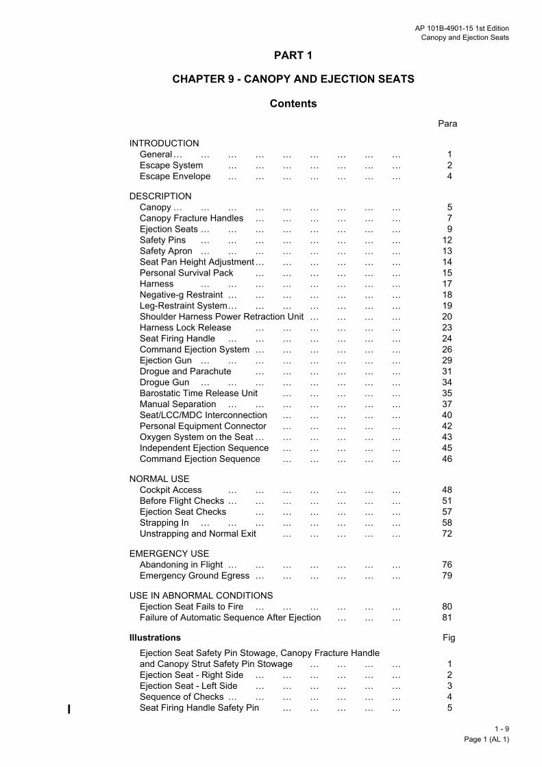
AP 101B-4901-15 1st EditionCanopy and Ejection Seats
PART 1
CHAPTER 9 - CANOPY AND EJECTION SEATS
ContentsPara
INTRODUCTIONGeneral… … … … … … … … … 1Escape System … … … … … … … 2Escape Envelope … … … … … … … 4
DESCRIPTIONCanopy … … … … … … … … … 5Canopy Fracture Handles … … … … … … 7Ejection Seats … … … … … … … … 9Safety Pins … … … … … … … … 12Safety Apron … … … … … … … … 13Seat Pan Height Adjustment… … … … … … 14Personal Survival Pack … … … … … … 15Harness … … … … … … … … 17Negative-g Restraint … … … … … … … 18Leg-Restraint System… … … … … … … 19Shoulder Harness Power Retraction Unit … … … … 20Harness Lock Release … … … … … … 23Seat Firing Handle … … … … … … … 24Command Ejection System … … … … … … 26Ejection Gun … … … … … … … … 29Drogue and Parachute … … … … … … 31Drogue Gun … … … … … … … … 34Barostatic Time Release Unit … … … … … 35Manual Separation … … … … … … … 37Seat/LCC/MDC Interconnection … … … … … 40Personal Equipment Connector … … … … … 42Oxygen System on the Seat … … … … … … 43Independent Ejection Sequence … … … … … 45Command Ejection Sequence … … … … … 46
Illustrations Fig
NORMAL USECockpit Access … … … … … … … 48Before Flight Checks … … … … … … … 51Ejection Seat Checks … … … … … … 57Strapping In … … … … … … … … 58Unstrapping and Normal Exit … … … … … 72
EMERGENCY USEAbandoning in Flight … … … … … … … 76Emergency Ground Egress … … … … … … 79
USE IN ABNORMAL CONDITIONSEjection Seat Fails to Fire … … … … … … 80Failure of Automatic Sequence After Ejection … … … 81
Ejection Seat Safety Pin Stowage, Canopy Fracture Handle and Canopy Strut Safety Pin Stowage … … … … 1Ejection Seat - Right Side … … … … … … 2Ejection Seat - Left Side … … … … … … 3Sequence of Checks … … … … … … … 4Seat Firing Handle Safety Pin … … … … … 5
1 - 9Page 1 (AL 1)

WAguof
Ge
1.em
Es
2.traindejesysthe
3.preor
Es
4.(se
MOR Handle … … … … … … … … 6
1 - Pag
INTRODUCTION
RNING: Death or serious injury is likely to occur to anyone near the cockpit if an ejection gun, droguen, linear cutting cord (LCC) or miniature detonating cord (MDC) is accidentally fired. Accidental operationan ejection gun results in the seat exploding from the aircraft.
neral
This chapter covers the canopy and the ejection seats, normal entry to and exit from the cockpits,ergency egress and rescue facilities and procedures.
cape System
In the primary mode the escape system gives the facility for ejection through the front and rear overheadnsparencies which are automatically cut or shattered by MDC systems. Each seat can be firedividually, or both seats can be fired by a command ejection facility. Canopy breakers are fitted to thection seat headboxes to assist penetration of the overhead transparency if the MDC fails. The MDCtems above the front and rear seats operate independently during normal separate seat ejections; bothse systems, together with a system at the front of the canopy, operate simultaneously if manually selected.
Static on-ground escape is by normal opening of the canopy, from either inside or outside. If damagevents normal opening, the transparency can be broken using the MDC, initiated from either crew station
MOR Firing Unit Sear … … … … … … … 7BTRU Static Trip Rod … … … … … … … 8Command Eject Pipes … … … … … … … 9BTRU Capsule … … … … … … … … 10Ejection Gun Firing Unit … … … … … … … 11Drogue Link Shackle … … … … … … … 12Parachute Container … … … … … … … 13Drogue Gun Piston… … … … … … … … 14Indicator Spigot & Plunger … … … … … … 15Drogue Gun Static Trip Rod … … … … … … 16Emergency Oxygen … … … … … … … 17Oxygen Regulator … … … … … … … … 18Go Forward Lever … … … … … … … … 19PSP Suspension Strap … … … … … … … 20Combined Harness … … … … … … … 21Sticker Straps … … … … … … … … 22Leg Restraint Attachment Points … … … … … … 23
by an external lanyard.
cape Envelope
The best possible chance of safe escape by ejection is given within the following envelope in Table 1e also Part 4, Chapter 2):
Table 1 - Safe Ejection Envelope
Altitude Ground Level to 35,000 feetMinimum level speed 70 knots at ground levelMaximum level speed 280 knots at ground levelMaximum dive speed 330 knots
9e 2

AP 101B-4901-15 1st EditionCanopy and Ejection Seats
DESCRIPTION
Canopy
5. The canopy is hinged on the right side, latched on the left side and covers both pilots. The fronttransparency is thicker than the rear, the two being joined by a metal hoop. A transparent blast screen onthe canopy between the cockpits protects the rear pilot if the front of the canopy is holed. A clearancebetween the blast screen and the canopy allows full demisting of the canopy. The whole is balanced toreduce opening or closing loads. A fabric loop is attached to the front grab handle to facilitate closing thecanopy when the pilot is strapped in. When open on the ground, wind speeds up to 40 knots can bewithstood. A ground locking pip pin is provided to lock a support strut in the open position. The locking pinhas a stowage at the left rear of the front cockpit. Experience of operating in high wind speeds shows that itis difficult, when strapped in, to control canopy opening/closing and impossible to insert the locking pip pin;therefore, in crosswind components of greater than 15 knots from the right or 20 knots from the left obtaingroundcrew assistance. When the canopy is unlocked an amber caption is illuminated on the CWP.
6. Both pilot positions have LCC/MDC systems. The front LCC is in two sections one of which severs theforward transparency above the seat and the other fractures the front of the canopy to facilitate groundegress. The rear MDC fragments the rear transparency. The two LCC/MDC sections above the seatsoperate independently as part of an ejection sequence. If required, all three LCC/MDC sections can beoperated simultaneously from inside or outside the aircraft. Should the LCC/MDC fail in an ejectionsequence, the canopy is penetrated by the breaker knives on the headbox of the front seat, and the breakerhorns on the headbox of the rear seat, to provide exit paths.
Canopy Fracture Handles
7. Internal. A CANOPY FRACTURE - PULL TO ARM/PUSH TO FIRE handle, striped black/yellow, is onthe right side in each cockpit (Fig 1). The handle is used to assist escape if any ground incident preventsnormal opening of the canopy. To operate the handle, remove the safety pin, pull the rear portion inwardsand then push it firmly forwards; this actuates all three cockpit LCC/MDC systems. The canopy fracturehandles are not cleared for airborne use.
8. External. Ground rescue of incapacitated crew is aided by either of two external canopy fracturehandles, one each side of the canopy rear frame. Each handle is housed within a hinged access panel whichhas a quick-release latch. A handle is connected to 5 m (17 feet) of cable. The operator should grasp ahandle and, facing away from the aircraft, take up the cable slack and then sharply tug the cable. When thetaut cable is tugged all three sections of LCC/MDC are exploded, irrespective of whether or not the internalcanopy fracture handles are secured by their safety pins.
Ejection Seats
9. Each cockpit has a Type 8LC Mk 1 ejection seat. The front seat, designated Mk 1-1, and the rear seat,Mk 1-2, are similar in operation but have individual features to cater for their particular cockpit and commandejection system. References to one seat apply to both unless stated otherwise. Each seat has a combinedseat and parachute harness. The parachute and drogue are contained at the seat top.
10. After ejection, separation of the harness and occupant from the seat and deployment of the parachuteoccur automatically. A manual separation facility can be used if any of the automatic functions fail or if man/seat separation is required prematurely. The seats can be fired individually or by command ejection whichis an automatic sequence (rear seat first) initiated by the firing of the rear seat.
11. Each seat has three main parts:
a. Ejection Gun. The ejection gun initiates the ejection and is fixed to, and stays in, the aircraft.
b. Main Beams. Two main beams ride on guide rails attached to the ejection gun. The beams carrythe parachute container and most of the seat operating devices.
c. Seat Pan. The adjustable seat pan rides on tubes on the main beams and has an upright backrestand a well to hold a personal survival pack (PSP).
1 - 9Page 3 (AL 1)

Safety Pins
12thethe
Sa
13flow
Se
14aftwhsho
Pe
15TheaDueith
16leftpaprestr
No
Ha
17by clipneUNsecbe
SeInhaNo
MNoM
Ca
1 - Pag
. All safety pins are listed in Table 2. The ejection seat safety pins are shown in Fig 2. A stowage for SEAT FIRING pin is on the left canopy frame in each cockpit. A 3-place stowage for the other pins is at rear of the front cockpit on the upper left side and visible to the front pilot only (Fig 1).
fety Apron
. A safety apron secures the PSP, the harness and the appendages of the rear seat when the aircraft isn solo. When not used the apron is stowed in a bag in the baggage compartment.
Table 2 - Canopy and Ejection Seat Pins
at Pan Height Adjustment
. Seat pan height is adjusted by an electrical actuator controlled by a SEAT ADJust - UP/DOWN (forward/ selection respectively) switch on the left console. Limit switches cut off the electrical supply (main busbar)en the seat pan reaches the end of its 15 cm (6-inch) travel. To avoid overheating the actuator, the facilityuld not be used continuously for more than one minute in any 8-minute period.
rsonal Survival Pack
. The PSP, which has a seat cushion attached to the top of its case, is housed in the well of the seat pan.e PSP is secured to the parachute harness by a strap which passes through two rings on the pack, one atch side; the end fittings on the strap are connected to two quick release side connectors on the harness.ring a parachute descent the PSP can be lowered and allowed to hang on a lowering line by disconnectinger of the side connectors.
Unit Pin Marking Type Responsibilityat firing handle (2) SEAT FIRING (red) T-bar Aircrew (2)
ternal canopy fracture ndle (2)
INTL CAN FRACTURE (black/yellow)
T-bar Aircrew (2)
te: Fitting of the above 4 pins makes the aircraft Safe for Parking.
anual override handle (2) MOR SEAR (red) Ring Groundcrewte: Fitting these 2 MOR SEAR pins, as well as the 4 Safe for Parking pins, makes the aircraft Safe for
aintenance.
nopy strut CANOPY STRUT (blue) Pip pin Air/Groundcrew
. The 4Q4 m (14Q5 feet) lowering line connects the PSP to the occupant. The line emerges from the front side of the pack and terminates at an end fitting retained by a sticker clip on the left inner side of the seatn. During strapping-in, a quick-release connector on an attachment strap at the left side of the lifeserver is secured to the end fitting. On man/seat separation after ejection, the life preserver attachment
ap automatically initiates operation of a personal locator beacon (PLB) in the life preserver.
te: The lowering line is not to be disconnected unless the PSP is to be jettisoned.
rness
. The harness secures the occupant to the parachute by lift webs integral with the harness, and to the seatharness locks on the seat. Two sticker straps (stickers) from the rear of the harness are retained by springs on the seat pan. The harness is secured on the occupant by a quick-release fitting (QRF) on the
gative-g strap, which in turn is locked to the seat pan. The QRF has a rotatable face marked TURN TOLOCK and PRESS TO RELEASE. Its two upper slots accept and lock the shoulder straps. The locks areure when a yellow notch on the face is uppermost. To engage the shoulder strap lugs, the QRF should
checked at the `locked' setting. After routing through the leg loop, the first shoulder strap lug is then
9e 4

AP 101B-4901-15 1st EditionCanopy and Ejection Seats
inserted and, with a firm push, locked. Repeat the process for the second shoulder strap. When the face ofthe QRF is rotated clockwise through 90L, a red line on the edge of the face is uppermost and the locks areprepared for release. Firm pressure on the face of the QRF then allows the shoulder straps to pull free.
WARNING: Because the QRF secures the occupant to both seat and parachute, the QRF is to be pressedonly when separation from the parachute is intended.
Negative-g Restraint
18. Negative-g restraint is provided by a strap secured to a harness lock at the front of the seat pan; theupper end of the strap is permanently attached to the QRF. Restraint is enhanced by a `V'-strap connectedbetween the negative-g lug at the bottom and the harness leg loops at the top.
Leg-Restraint System
19. An automatic leg-restraint system holds the occupant's legs against the seat pan during ejection. Fromshear pins on the cockpit floor, two lines are routed through one-way snubbers on the seat pan and rings onthe occupant's leg garters to taper plugs in locks on the sides of the seat pan. The snubbers allow the linesto be tightened as the seat rises and the shear pins break when the legs are restrained. The snubbersmaintain their grip until man/seat separation. The taper plug locks are released to free the legs when theman portion of the personal equipment connector (PEC) (para 42) is released either manually (normal, afterflight) or automatically (after ejection). Two snubber release controls in the frontal recess of the seat allowthe lines to be lengthened for strapping in.
Shoulder Harness Power Retraction Unit
20. The seat shoulder harness is connected by roller fittings to two looped retraction straps above the seatpan. The retraction straps are attached at one end to individual harness locks and at the other to a cartridge-operated power retraction unit. The retraction unit has two spring-loaded spools around which the straps arewound, and a ratchet mechanism which can lock the spools to prevent extension of the straps.
21. The ratchet is normally controlled by a 2-position go-forward control lever on the left side of the seat pan.The lever has to be lifted before its position can be changed. When the lever is forward (unlocked), theoccupant can lean forward against spring pressure to a maximum of 30 cm (12 inches). When the lever isaft (locked) the spools take up any slack in the retraction straps to prevent forward movement. If, with thelever forward, the retraction straps are extended at an excessive rate (e.g. during rapid deceleration), theratchet automatically and immediately engages to prevent any further forward movement of the occupant.After the load on the straps has been relaxed, forward movement is again possible.
WARNING: If there is insufficient deceleration to engage the ratchet and the go-forward lever is forward, theseat occupant may be thrown forward and/or downward resulting in his head striking the coaming or the topof the control column. This situation may be met during a heavy landing, turbulence at low level or a barrierengagement. Therefore, the go-forward lever is always to be selected to the rear for take-off, flight in severeturbulence and landing.
22. When ejection is initiated, a retraction unit cartridge fires; the resultant gas pressure powers theretraction unit which winds in the retraction straps, pulling the occupant's shoulders back into the seat.
Harness Lock Release
23. The lock release system frees all of the man/seat connections automatically after ejection or when themanual separation handle is pulled. The locks are in two groups:
a. Top Locks. Two top locks secure the retraction straps and thus the shoulder harness.
b. Bottom Locks. The bottom locks secure the harness lap straps (two), the negative-g strap (one),and the man portion of the PEC (one) which is interconnected with the leg-restraint taper plugs (two).
1 - 9Page 5

Seat Firing Handle
24redshabefire
25sep Ejection Seat Safety Pin Stowage, Canopy Fracture Handle and Canopy Strut Safety Pin Stowage
1 - Pag
. The seat firing handle is a black and yellow flexible loop at the front of the seat pan. The handle has a SEAT FIRING safety pin which is to be removed and stowed after strapping in. When the handle is pulledrply upwards (20 to 70 lb pull force) it moves approximately 4 cm (1Q5 inches) to fire a cartridge, before
ing restrained. Gases from the cartridge operate the harness power retraction unit, the MDC initiator and the seat ejection gun. On the rear seat, the gases also fire a command ejection cartridge.
. The firing handle also controls a mechanical safety lock, which prevents operation of the manualaration handle until the seat firing handle has been pulled fully upwards.
1 - 9 Fig 1 Ejection Seat Safety Pin Stowage, Canopy Fracture Handle and Canopy Strut Safety Pin Stowage
9e 6

AP 101B-4901-15 1st EditionCanopy and Ejection Seats
Command Ejection System
26. The command ejection system interconnects the firing systems of the seats, and allows the sequencedejection of both seats to be initiated from the rear cockpit. A COMMAND FIRING - ON/OFF lever is in therear cockpit on the aft bulkhead at the lower left side. When the lever is at ON (up) the command system isoperative. At OFF (down), the command system is inoperative.
27. A cartridge at the selector valve fires when the rear seat firing handle is pulled; the sequence thendepends on the setting of the firing lever:
a. With the lever ON, the cartridge gases are passed to the front seat and immediately operate thefront seat power retraction unit. After a delay of 1Q4 seconds, the gases fire a breech unit cartridge inthe front cockpit to initiate the firing of the front seat ejection gun.
b. With the lever OFF, the cartridge gases exhaust into the rear cockpit with no effect.
28. The command firing lever is lift-guarded at both settings and has a rotatable knurled knob, used to lockthe lever at the selected setting. The lever setting is altered by rotating the knob counter-clockwise, liftingthe lever against spring pressure and moving it to the new setting (up for ON, down for OFF), where it canbe correctly located when released. The lever may then be locked at the new setting by rotating the knobfully clockwise. To avoid difficulties in releasing the lever for subsequent sorties, the lever should not betightened hard against the stop.
WARNING: The front seat firing handle remains effective (for front seat independent ejection) irrespective ofthe setting of the command firing lever.
Ejection Gun
29. Seat ejection is initiated by the telescopic ejection gun, powered by a primary and two secondarycartridges which fire in sequence. The gun barrel is fixed to the aircraft and the seat is attached to the innerof two sliding tubes, which are locked within the barrel by a top latch mechanism. During ejection the slidingtubes extend. The outer tube forms an extension of the gun barrel and remains with the aircraft. The innertube is ejected with the seat.
30. The gun is fired when the seat firing handle is pulled (or, on the front seat only, when the commandejection system operates). Gas pressure from the firing unit cartridge (or the command breech unit cartridge)fires the primary cartridge. Gas from the primary cartridge initiates upward movement of the tubes. As thetubes rise, ports are opened which allow the primary cartridge gas to ignite the secondary cartridges in turn.
When the tubes are fully extended, separation of the inner and outer tubes occur. The seat is then free ofthe aircraft.
Drogue and Parachute
31. A drogue is packed with an aeroconical personal parachute in the container at the top of the seat. Thedrogue is deployed automatically to stabilize and retard the seat, before deployment of the parachute towhich it is attached. The top of the parachute container is covered by fabric closure flaps and secured by aclosure pin, which is withdrawn automatically during the ejection sequence.
32. The drogue is deployed by a withdrawal line attached to a drogue gun piston, and in turn is attached toa parachute withdrawal line. The parachute withdrawal line is secured by a gas operated piston at the top ofthe seat beams, and is further restrained within the parachute container. Operation of a barostatic timerelease unit releases both the container restraint and the drogue shackle, allowing the drogue to deploy theparachute.
33. The aeroconical parachute is designed to travel horizontally (as well as vertically) after deployment, withthe occupant facing the direction of horizontal movement. The horizontal component, although small, resultsin improved stability and a relatively low rate of descent. The parachute is steerable via two lines routed downthe front lift webs, one line on each web. With the parachute canopy inflated, pulling down a hand-loop atthe end of the appropriate line, turns the parachute in that direction (i.e. pull the left line to turn left, and vice
1 - 9Page 7

versa); the loop should be pulled down to shoulder level for maximum steering response. To stop the turn,gra
Dr
34a pan0Q6reldro
Ba
35reltheTwde
36
Ma
37catsea
38of meaftBTup
WAcau
1 - Pag
dually relax the pull on the line and allow the line to rise to its original position.
ogue Gun
. The drogue gun, on the top left side of the seat, is fired automatically by a trip rod. The drogue gun ejectsiston, which (via an attached line) removes a pin securing closure flaps on top of the parachute container,d then deploys the drogue. The gun has two separate cartridges, one mechanically fired by the trip rod second after the trip operates during ejection, the other gas fired by the action of the barostatic timeease unit, or by the operation of the manual separation handle. A shear pin is fitted through the top of thegue gun barrel to retain the piston until the gun fires.
rostatic Time Release Unit
. The barostatic time release unit (BTRU) on the top right side of the seat provides for the automaticease of the drogue shackle, deployment of the personal parachute, and separation of the occupant from seat after ejection. The deployment/separation sequence occurs when a cartridge in the BTRU is fired.o devices in the BTRU (a time delay mechanism and a main barostat) delay the firing of the cartridge,pending on the ejection conditions:
a. Time Delay. The mechanical time delay is triggered by a static trip rod when the ejection seat startsto rise during the ejection sequence. If the delay mechanism is unobstructed (see sub para b. below), itallows the BTRU cartridge to fire 1Q5 seconds after seat ejection.
b. Main Barostat. After ejection at altitude, the main barostat prevents operation of the time delay untilthe man/seat have descended to an altitude where tolerable oxygen/temperature conditions exist. Thebarostat has a normal setting of 10,000 feet (pressure altitude). After ejection, the drogue-stabilized seatdescends rapidly with the occupant still strapped in. At 10,000 feet the barostat removes its restraint onthe time delay, which is then free to operate.
. When the BTRU cartridge fires, the resultant gas simultaneously:
a. Operates a release mechanism to free the restraint on the parachute withdrawal line within theparachute container.
b. Operates a piston which releases the drogue shackle and releases the top locks of the harness.The release of the drogue shackle frees the drogue from the seat, thereby initiating deployment of thepersonal parachute.
c. Releases the harness bottom locks, allowing the occupant to be pulled from the seat as theparachute develops.
d. Fires the second cartridge of the drogue gun. This overcomes any failure of the mechanical firingof the gun and is normally a redundant action.
nual Separation
. The manual separation facility provides an alternative method for firing the drogue gun and BTRU, thusering for the failure of either or both, allowing the occupant to deploy the parachute and separate from thet if the automatic sequence of actions fails, or if it is desired to achieve separation prematurely.
. The facility is operated by a black and yellow striped Manual Over-Ride (MOR) handle on the right sidethe seat pan (see Fig 2); a thumb button on top of the handle must be held pressed to release achanical lock before the handle can be pulled. When the MOR handle is pulled a cartridge in a firing unit of the handle is detonated, and produces gases which operate the mechanisms normally operated by theRU. A safety lock prevents operation of the MOR handle until the seat firing handle has been pulled fullywards.
RNING: If the front seat is ejected via the command ejection system, and the occupant subsequently hasse to use the manual separation facility, he must first pull his seat firing handle.
9e 8

AP 101B-4901-15 1st EditionCanopy and Ejection Seats
39. The MOR firing unit sear, on the right side of the seat, has a safety pin marked MOR SEAR which is tobe checked as having been removed from the sear and stowed before strapping-in. Ensure that there areno foreign objects between the seat and the right console.
Ejection Seat - Right Side
HEAD REST
LIFT WEBS
BACK PAD
QUICK-RELEASEFITTING
NEGATIVE-GSTRAP
LOWERING LINELUG ARROWHEADCONNECTOR
MOR FIRING UNIT
LAP STRAP
STICKER STRAP
MOULDED BACK REST
BACK PLATE
BTRU TRIP ROD
BACK PLATECAPTIVE PIN
UPPER HARNESSLOCK
BAROSTATIC TIMERELEASE UNIT
SHOULDER STRAPSTOWAGE
CANOPY BREAKER
1 - 9 Fig 2 Ejection Seat - Right Side
SEAT FIRING HANDLESAFETY PIN
SEAT FIRINGHANDLE LINKAGE
LEG RESTRAINT LINES
LEG RESTRAINT LINETAPER PLUG LOCKHOUSING
MOR HANDLE
SEAR AND SAFETY PIN
HS/TUC/0311
1 - 9Page 9

Ejection Seat - Left Side
Se
40thecan
41tra
Notheha
1 - Pag
1 - 9 Fig 3 Ejection Seat - Left Side
DROGUEWITHDRAWAL LINE
DROGUE GUN
SHOULDER HARNESSPOWER RETRACTIONUNIT
DROGUE GUNSTATIC TRIP ROD
SEATCROSS BEAM
EMERGENCYOXYGEN STRIKER
EMERGENCY OXYGENCYLINDER OPERATINGLEVER
PEC DUSTCOVER ANDLATCH HANDLE
OXYGEN SUPPLY
PSP SINGLE HANDEDRELEASE LINE ANDQUICK RELEASE CONNECTOR
OXYGEN REGULATORASSEMBLY
EMERGENCY OXYGENHANDLE
GO-FORWARD HANDLE
SEAT CUSHION
LEG LINESNUBBING UNIT
CROTCH STRAPS
SEAT FIRING HANDLE
SHOULDER STRAPS
HS/TUC/0310
at/LCC/MDC Interconnection
. Gas pressure from the firing unit cartridge causes the canopy fragmentation initiators to fire, detonating LCC/MDC firing unit on the canopy frame. The LCC/MDC severs/fractures the associated section ofopy before contact with the seat. If the LCC/MDC fails the seat ejects through the canopy.
. The canopy breaker knives (front seat) and horns (rear seat) are designed to cut and weaken the intactnsparency before the remainder of the seat structure and occupant contact it.
te: The seat/LCC/MDC interconnection operates to sever/fracture only that section of the canopy above seat from which the ejection is made, whereas operation of either of the internal CANOPY FRACTURE
ndles causes severing/fracturing of the entire canopy (i.e. front section and both sections above the seats).
9e 10

AP 101B-4901-15 1st EditionCanopy and Ejection Seats
Personal Equipment Connector
42. A PEC, on the left side of the seat pan (Fig 3), provides single action connection of the occupant's mic/tel and oxygen supplies before flight; it also provides disconnection after flight and automatically during theejection sequence. The PEC comprises seat and man portions:
a. Seat Portion. The seat portion provides for connection of the man portion on its top face. It is lockedto the seat pan and is coupled to the oxygen regulator. A catch at the aft end of the seat portion enablesthe whole unit to be removed for maintenance. A metal dust cover, provided to protect the seat portionwhen the seat is not occupied, is stowed on the cockpit aft bulkhead. The time when the seat portion isnot covered by either the dust cover or the PEC man portion (para 42b) is to be kept to a minimum.
b. Man Portion. The man portion is part of the flying clothing and has an oxygen tube and mic/tel leadwhich are to be connected to the occupant's oxygen mask hose and helmet mic/tel lead respectively.The man portion is connected by aligning it over the seat portion, locating its front end and pressing downfirmly on its aft end until it locks into place. It is released manually by pulling up its latch handle afterpressing a thumb catch on the handle. It is released automatically after ejection by a linkage from theharness lock release mechanism. Both release methods also disconnect the leg-restraint lines.
Note 1: During the strapping-in procedure, to prevent the possibility of surplus oxygen tube and mic/tel leadfouling the pilot's elbow, pull them forward through the restraint flap on the life preserver to minimize thelength between the flap and the PEC.
Note 2: The man portion is not to be connected to the seat portion until after the main oxygen supply hasbeen selected ON; it is to be disconnected and the dust cover fitted before the oxygen supply is selected OFFafter flight.
Oxygen System on the Seat
43. The main oxygen system is connected to the seat at an automatic pull-off bayonet connector behind theright side of the seat pan, and thence by pipe and flexible tube to the regulator/PEC.
44. An emergency oxygen cylinder on the rear left of the seat feeds into the main supply line and has asupply release mechanism which is tripped automatically by a striker during ejection, or can be operatedmanually at any time by pulling sharply upwards and backwards on a control handle on the left side of theseat pan.
Independent Ejection Sequence
45. To ensure safe separation between seats a minimum interval of 1Q4 seconds between the rear seat andfront seat ejections is desirable when the rear seat independently ejects first. When independent ejection isinitiated, i.e. the command firing lever is at OFF or, with the lever at ON, the front seat firing handle is pulledbefore the rear seat handle, the following sequence occurs:
a. The seat firing unit cartridge fires immediately and movement of the seat handle releases a lock,which enables the manual separation handle.
b. Gases from the firing unit are distributed to:
(1) Harness Power Retraction Unit. The harness power retraction unit cartridge fires to pull theoccupant's shoulders back into the seat and lock the retraction straps.
(2) Seat Ejection Gun. Fires the primary cartridge of the ejection gun.
(3) Canopy Fragmentation System. The canopy detonator(s) are initiated.
(4) Command Eject Selector Valve. Fires the command ejection cartridge and, with thecommand firing lever selected OFF, the gases are vented into the rear cockpit.
1 - 9Page 11

Note: If the command firing lever is selected ON and the front seat handle is pulled first, the gases from
Co
46seafedthe
47alsshotheeje
1 - Pag
the Command Ejection Selector Valve pass to the front cockpit but have no effect since the front seathas already ejected.
c. Gases from the ejection gun primary cartridge initiate upward movement of the seat, releasing thelocking plunger from the top latch and thus unlocking the seat from the gun barrel.
d. As the seat accelerates up the guide rails, the following events occur automatically:
(1) The ejection gun secondary cartridges fire in turn.
(2) The static trip rods withdraw the sears from the drogue gun and the BTRU, and static cablesdisconnect the command ejection system, the main oxygen supply and the mic/tel supply.
(3) The emergency oxygen supply is initiated and the regulator is set to 100%.
(4) The leg restraint lines are pulled downwards through the snubbing units and restrain theoccupant's legs. The units maintain the restraint after the shear pins break to free the lines from thefloor.
e. The drogue gun fires, ejecting its piston which withdraws the pin from the closure flaps on theparachute container and deploys the drogue. The drogue is fully developed approximately one secondafter initiation of ejection.
f. The remainder of the sequence is controlled by the BTRU:
(1) Above Main Barostat Altitude. If the ejection is made above main barostat altitude, the seatdescends to that altitude band and the main barostat then allows the 1Q5 second time delaymechanism to operate and fire the BTRU cartridge.
(2) Below Main Barostat Altitude. If the ejection is made below the main barostat altitude the timedelay then operates and fires the BTRU cartridge.
g. When the BTRU cartridge fires, its gases cause the drogue shackle and the harness top locks to bereleased; the gases also release the harness bottom locks and pass to the drogue gun to fire its secondcartridge (normally a redundant action).
h. The release of the harness locks frees, but does not separate, the occupant from the seat. Therelease of the drogue shackle transfers the drag of the drogue to the personal parachute which is thenpulled from its container.
i. The occupant is then held in the seat only by the restraint of the seat pan stickers. As the parachute
develops it lifts the occupant and the PSP from the seat, pulling the seat pan stickers and PSP loweringline connector from their clips (the latter initiating PLB operation). The occupant must release his gripon the seat firing handle at or before this stage. The seat then falls away cleanly and the leg restraintlines run out freely through the rings on the leg garters. A normal parachute descent should then follow.
mmand Ejection Sequence
. The following ejection sequence occurs when the command firing lever is at ON and the ejection of bothts is initiated by pulling the rear seat firing handle. When the rear seat firing unit cartridge fires, gases are to the command ejection selector valve firing its cartridge. The ejection of the rear seat continues as in independent sequence.
. From the selector valve cartridge gases are passed to the command breech unit in the front cockpit, ando (via a bypass) to the front harness power retraction unit which immediately pulls the occupant'sulders back into the seat. After a 1Q4-second delay the command breech cartridge fires which in turn fires front ejection gun, thus initiating seat ejection; the sequence then continues as in the independentction sequence.
9e 12
AP 101B-4901-15 1st EditionCanopy and Ejection Seats
WARNING: If the command ejection system is operative (i.e. selected ON), removal of the rear seat firinghandle safety pin renders the front seat live, whether or not the front seat firing handle safety pin is fitted.
NORMAL USE
Cockpit Access
48. General. Avoid handling the transparencies. When entering or leaving the cockpit, do not use the glareshield as a handhold. Take care that the PEC shoe does not swing freely and damage cockpit installations.
49. Canopy Opening from Outside. Pull out the release handle on the left side of the fuselage at the rearcockpit and turn it fully clockwise. This disengages the locking mechanism and enables the canopy to belifted open using the external handle at the rear cockpit position.
50. Canopy Operation from Inside
a. Closing. In either cockpit use the grab handle to pull the canopy down to the closed position againstthe counterbalancing mechanism; in the front cockpit it may be necessary to use the fabric loop. Ensurethe fabric loop is not trapped between the canopy and cockpit sill. While holding the canopy down takehold of the handle on the front left wall and, turning the handle through 90L to form a crank, rotate thelever clockwise until a positive locking click is felt or heard; considerable force may be required to obtaina lock. Ensure that the canopy caption on the CWP extinguishes.
b. Opening. In either cockpit the lever on the front left wall releases the locking mechanism. Pull thehandle away from the lever axis and turn it through 90L to form a crank. Rotate the lever counter-clockwise. Raise the canopy using the internal handle at the front cockpit position.
Before Flight Checks
51. On donning the life preserver, check that the PEC oxygen tube and mic/tel lead are routed through theflap on the life preserver. Check that the oxygen and mic/tel connections are properly made at the PEC manportion and secure the PEC oxygen tube to the front of the life preserver by the dog-lead clip.
52. Before dual or solo flight check that the aircraft is Safe for Parking and that both MOR pins have beenremoved and stowed. Check both cockpits for loose articles, particularly for foreign objects lodged betweenthe ejection seat and the right hand console.
WARNING: The front ejection seat canopy breaker knives are very sharp. Take care to avoid injury whencarrying out Ejection Seat checks and entering the cockpit.
53. The SEAT FIRING pins are to remain in the seat until after strapping in, the canopy has been closed andthe engine started. When stowed, the pins are visible from outside to enable the groundcrew to check thatthe aircrew have removed and stowed the seat pins in both cockpits (dual sortie) or the front cockpit seat pin(solo sortie), before flight.
Note: The INTL CAN FRACTURE pins remain in the canopy handles at all times during normal operation.
54. In the rear cockpit, confirm the command ejection selector OFF, checking that the lever is correctlylocated. Turn the rear cockpit oxygen supply ON if dual, OFF if solo.
55. Before solo flight check:
a. The rear seat firing handle and ejection seat firing handle safety pins are both visible.
b. The rear seat safety apron is securely fitted and tightened over the locked and tightened harness.The top of the apron is secured by two pip9pins which locate with two press studs secured to the yokestrap.
c. The rear cockpit leg9restraint and PSP lowering lines are secure.
1 - 9Page 13

d. The skirt of the apron is tucked around the seat cushion and PSP.
56
Eje
57hache
1 - Pag
. Turn the front cockpit oxygen supply ON.
ction Seat Checks
. To avoid the risk of inadvertently disconnecting seat components, only those items which are normallyndled during strapping-in should be subjected to a physical check. The remainder of the seat should becked visually.
a. Carry out the Ejection Seat checks given in the Flight Reference Cards (itemised within Fig 4) whichare amplified below:
Sequence of Checks
1 - 9 Fig 4 Sequence of Checks
9e 14

AP 101B-4901-15 1st EditionCanopy and Ejection Seats
(1) Confirm that the seat firing handle is fully engaged onto the seat firing handle housing. Checkthat the seat firing handle safety pin is fitted through both the seat firing handle and the seat firinghandle housing. (Fig 5). Seat Firing Handle Safety Pin
1 - 9 Fig 5 Seat Firing Handle Safety Pin
(2) Ensure that the MOR handle is locked down with the thumb button fully out (Fig 6) and the firingunit safety pin has been removed and stowed (Fig 7). MOR Handle
1 - 9 Fig 6 MOR Handle MOR Firing Unit Sear
1 - 9 Fig 7 MOR Firing Unit Sear
1 - 9Page 15 (AL 1)

(3) Ensure the BTRU static trip rod is secured to the cross beam with a pip pin (yellow-white-yellow-
1 - Pag
white) (Fig 8). BTRU Static Tr ip Rod
1 - 9 Fig 8 BTRU Static Trip Rod
(4) Visually confirm that the command ejection pipe(s) (two on front seat/one on rear seat) are notdisconnected from the ballistic manifold (Fig 9). Command Eject Pipes
White Telltale
BallisticManifold
Pip Pin
Telescopic Tubes
1 - 9 Fig 9 Command Eject Pipes
(5) Ensure that the command (seat firing (fwd inboard)) and BTRU (manual separation (fwdoutboard)) telescopic tubes are securely attached with a pip pin to the ballistic manifold and thewhite telltale is flush (Fig 9).
HS/TUC/0312
CommandEject Pipe
9e 16

AP 101B-4901-15 1st EditionCanopy and Ejection Seats
(6) Check the BTRU capsule has the correct operating altitude (Fig 10). BTRU Capsule
1 - 9 Fig 10 BTRU Capsule
(7) Ensure that the ejection gun firing unit latch plunger is engaged and the quick-release pip pinfitted. The latch plunger should be flush with the housing, but due to manufacturing tolerances asmall gap may be present (Fig 11). Ejection Gun Firing Unit
1 - 9 Fig 11 Ejection Gun Firing Unit
(8) Check the drogue shackle is secured to the drogue link shackle and the tie is intact. Check the
drogue link shackle is secure in the piston housing (Fig 12). Drogue Link Shackle
1 - 9 Fig 12 Drogue Link Shackle
1 - 9Page 17

(9) Ensure that the parachute container closure flaps are closed and secured over the drogue
1 - Pag
withdrawal line and that the two ties are intact (Fig 13). Parachute Container
1 - 9 Fig 13 Parachute Container
(10) Ensure the drogue withdrawal line is attached to the drogue gun piston (Fig 14) and that theshear pin is fitted. Drogue Gun Piston
1 - 9 Fig 14 Drogue Gun Piston
(11) Ensure that the seat is correctly locked to the ejection gun by checking that the top latchindicator spigot (inner plunger) is flush with or slightly protrudes from the end of the latch plungerand that the top latch plunger is flush with or slightly recessed in the end of the housing face(Fig 15).
Indicator Spigot & Plunger
1 - 9 Fig 15 Indicator Spigot & Plunger
9e 18

AP 101B-4901-15 1st EditionCanopy and Ejection Seats
(12) Check the drogue gun static trip rod is secured to the cross beam with a pip pin (yellow-white-yellow-white), see (Fig 16). Drogue Gun Static Trip Rod
1 - 9 Fig 16 Drogue Gun Static Trip Rod
(13) Ensure the emergency oxygen contents gauge indicates full (green mark) and the pip pin isfitted. Ensure the manual control handle is fully down and the trip lever has not been operated.Ensure that the emergency oxygen striker is in the extended position (Fig 17). Emergency Oxygen
1 - 9 Fig 17 Emergency Oxygen
(14) Set the oxygen regulator to AM (forward), see (Fig 18). Oxygen Regulator
1 - 9 Fig 18 Oxygen Regulator
1 - 9Page 19 (AL 1)
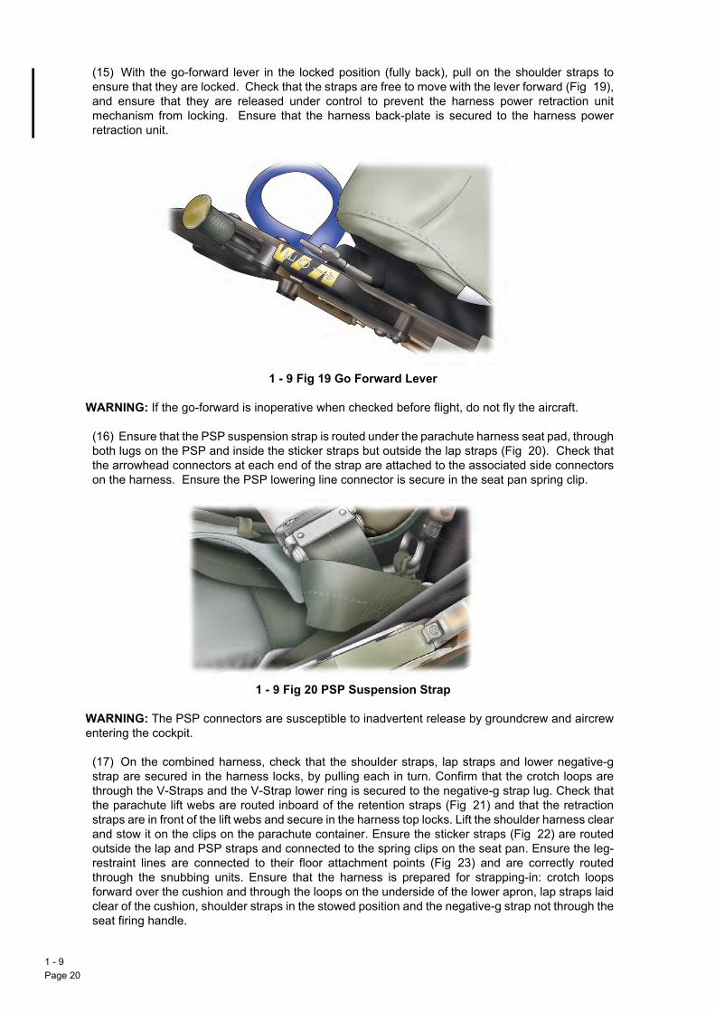
(15) With the go-forward lever in the locked position (fully back), pull on the shoulder straps to
1 - Pag
ensure that they are locked. Check that the straps are free to move with the lever forward (Fig 19),and ensure that they are released under control to prevent the harness power retraction unitmechanism from locking. Ensure that the harness back-plate is secured to the harness powerretraction unit. Go Forward Lever
1 - 9 Fig 19 Go Forward Lever
WARNING: If the go-forward is inoperative when checked before flight, do not fly the aircraft.
(16) Ensure that the PSP suspension strap is routed under the parachute harness seat pad, throughboth lugs on the PSP and inside the sticker straps but outside the lap straps (Fig 20). Check thatthe arrowhead connectors at each end of the strap are attached to the associated side connectorson the harness. Ensure the PSP lowering line connector is secure in the seat pan spring clip. PSP Suspension Strap
1 - 9 Fig 20 PSP Suspension Strap
WARNING: The PSP connectors are susceptible to inadvertent release by groundcrew and aircrewentering the cockpit.
(17) On the combined harness, check that the shoulder straps, lap straps and lower negative-gstrap are secured in the harness locks, by pulling each in turn. Confirm that the crotch loops arethrough the V-Straps and the V-Strap lower ring is secured to the negative9g strap lug. Check thatthe parachute lift webs are routed inboard of the retention straps (Fig 21) and that the retractionstraps are in front of the lift webs and secure in the harness top locks. Lift the shoulder harness clearand stow it on the clips on the parachute container. Ensure the sticker straps (Fig 22) are routedoutside the lap and PSP straps and connected to the spring clips on the seat pan. Ensure the leg-restraint lines are connected to their floor attachment points (Fig 23) and are correctly routedthrough the snubbing units. Ensure that the harness is prepared for strapping-in: crotch loopsforward over the cushion and through the loops on the underside of the lower apron, lap straps laidclear of the cushion, shoulder straps in the stowed position and the negative-g strap not through theseat firing handle.
9e 20

AP 101B-4901-15 1st EditionCanopy and Ejection Seats
Combined Harness
1 - 9 Fig 21 Combined Harness Sticker Straps
1 - 9 Fig 22 Sticker Straps Leg Restraint Attachment Points
1 - 9 Fig 23 Leg Restraint Attachment Points
1 - 9Page 21

Strapping In
WAgroof
WAswsea
WAdu
WAare
58thelea
59roustic
60at apre
61paSimrig
Noharecare
62legthrsnu
63the
64anbrileft
WAstran
65unthebe
1 - Pag
RNING 1: To prevent the leg-restraint line taper plugs snagging during pull through on an emergencyund egress, it is important that the leg garters are worn with their quick-release connectors on the inside
the leg. The free end of the garter adjustment strap should be at least 25 mm away from the outer D-ring.
RNING 2: Ensure that all loose objects are safely stowed before operating the SEAT RAISE"LOWERitch. Ejection seat components may be damaged, and ejection sequences inadvertently initiated, if thet is raised or lowered with objects under the seat or between the seat and side consoles.
RNING 3: When strapping in ensure that there is no possibility of the AEA fouling seat mechanismsring subsequent ground operations and flight.
RNING 4: Because a command ejection system is fitted, do not move any safety pins until both occupants correctly strapped in and the canopy is closed.
. Lay the lap straps clear and occupy the seat, taking care not to stand on the seat firing handle. Adjust rudder pedals and set the go-forward lever to its locked (aft) position. Move the back pad fully up beforening back into the seat.
. Connect the quick-release connector on the left side of the life preserver to the PSP lowering line,teing the strap outside the left thigh. Re-check that the lowering line end fitting is secure in the seat panker clip and that the line is below all hoses and the lap strap.
. Lay the left lap strap on the left thigh. Connect the PEC by offering the man portion to the seat portionn angle in excess of 45L and pushing the man portion forward into the guide slot as far as possible beforessing down into position, ensuring its security.
. Pass the left leg-restraint line from the snubbing unit through the garter rings on the front of the left leg,ssing the line from inboard to outboard, and insert the taper plug in the lock on the left side of the seat pan.
ilarly pass the right leg-restraint line through the rings on the right garter and secure its taper plug on theht of the seat pan. Ensure that the lines are not crossed and are not snagging the lower negative-g strap.
te: If necessary the taper plug locks can be checked for release at this stage by pulling up the PEC latchndle to release the man portion. The taper plugs should eject from their locks. The PEC is to beonnected and the taper plugs again inserted in their locks, care being taken to ensure that the connections secure.
. Adjust the leg-restraint lines so that there is just sufficient line above the snubbing units to allow enough movement for the application of full rudder in both directions. Pull any excess leg-restraint line downough the snubbing units. If the lines prevent the application of full rudder in both directions, operate thebbing release controls in turn and pull up the required amount of line.
. Bring the negative-g strap and attached QRF up between the legs, ensuring it is aft of, and not through, seat firing handle. Check that the QRF is locked, i.e. yellow notch on the face uppermost.
. Bring the left leg loop up inside the left thigh, ensuring it is aft of, and not through, the seat firing handled pass it through the left lap strap D-ring from below. Fold the leg loop through 90L using a forward twist,ng down the left shoulder strap and pass its lug through the left leg loop, push the lug down into the QRF slot until the lug is securely locked. Repeat the process for the right side of the harness.
RNING: Positively check that the shoulder strap lugs are locked in the QRF before tightening the lapaps. Tightening the lap straps causes the lugs to geometrically lock in the QRF slots; this may disguise insecure lug.
. Check that the PEC supplies are outside of the left lap strap, and the life preserver attachment strap isder the left lap strap; check that the oxygen tube is under the left shoulder strap. Pull the oxygen tube and mic/tel lead forward through the restraint flap on the life preserver to reduce to a minimum the surplus
tween the flap and the PEC.
9e 22

AP 101B-4901-15 1st EditionCanopy and Ejection Seats
66. Fully tighten the lap straps, positioning the QRF centrally.
67. Fully tighten the shoulder straps ensuring that the QRF remains in a central position. Have any slackpulled rearwards through the shoulder D-rings and tucked away behind the shoulders. At this stage thetension in the shoulder straps should be slightly overtight. It is this degree of overtension which extracts thecorrect amount of harness power retraction unit blue strap when the go-forward lever is unlocked.
68. Check that the shoulder straps are clear of the lobes and inflation handle of the life preserver.
69. With power applied, adjust seat pan height so that the head is approximately centred on the headrest ofthe seat.
WARNING: Adjusting the seat too high can result in backache, head and spinal injuries during ejection andfouling of the control column by the knee or thigh. Once strapped in the occupant may adjust the seat heightto improve visibility for taxying and manoeuvring, but the seat should be returned to the normal in-flightposition before take-off.
70. Set the go-forward lever to its forward (unlocked) setting and lean forward to extend the shoulder straps.Set the go-forward lever aft (locked) and slowly sit firmly back into the seat while checking for correct lockingof the power retraction unit. Re-tighten the shoulder straps firmly. At this stage ensure that approximately 2to 3 inches of the inertia reel blue webbing strap is horizontal and clear of the inertia reel fairing blocks(groundcrew assistance is an advantage) and that the shoulder strap adjustment buckles lie comfortablyforward on the shoulder (below the collar bone).
Note: If a shoulder strap becomes twisted when leaning forward, the strap may jam during retraction. Tountwist, pull the strap directly forward manually and allow it to retract slowly into its housing.
WARNING: To avoid an increased likelihood of serious back injury, do not tighten the shoulder harnessstraps with the go9forward lever in the forward position.
71. Finally, check that there are no straps or lines routed through the ejection seat firing handle.
Unstrapping and Normal Exit
72. Make the aircraft Safe for Parking and then, with oxygen mask donned and visors down, open thecanopy.
73. Release the oxygen mask. Disconnect the PEC man portion.
74. Ensure the PSP lowering line is disconnected. Pull the leg-restraint lines free of the leg garter rings.Release the harness by rotating and then pressing the QRF face; free the shoulder straps from the QRF andreturn the face of the fitting to the locked setting. Slip the leg loops from the lap strap D-rings and lay thestraps clear.
75. Fit the dust cover to the PEC seat portion. Stand up and stow the shoulder straps on the parachutecontainer. Fit the canopy strut pin if required. Vacate the cockpit.
Note: If the harness shoulder straps are incorrectly stowed they may cause jamming of the seat, when itsheight is adjusted, and lead to the release of the harness top locks. It is essential therefore, to ensure thatthe shoulder straps are correctly stowed.
1 - 9Page 23

EMERGENCY USE
Ab
76If tthe
77con
78hemaimp
WAspl
Em
79imp
Eje
80seain s
Fa
81the
82wittheBTimm
WAto
83illu
1 - Pag
andoning in Flight
. To carry out a normal ejection, complete as much of the Abandoning drills as time and conditions permit.he command firing lever has been selected OFF the front crew member should delay 1Q4 seconds after rear crew member has ejected to ensure adequate separation.
. At low altitude the aircraft should be in substantially level flight to provide the optimum ejectionditions. Allow additional terrain clearance if the aircraft is descending or in an extreme attitude.
. At altitude the aircraft attitude is not important but, in controlled ejection conditions, adjust speed andight before ejection. Ideally, position the aircraft over an unpopulated area. Set aileron trim at one-halfximum in either direction and set the throttle to FLT IDLE before ejection; subsequently the aircraft shouldact within a short radius of the ejection point.
RNING: If a parachute descent is being made into water it is important to lower the PSP beforeashdown, since the side connectors may be difficult to operate in the water.
ergency Ground Egress
. Do not use the ejection seats on the ground with less than 70 knots indicated. When stationary, if it isossible to open the canopy normally, leave the aircraft using the procedure given in Part 4, Chapter 2.
USE IN ABNORMAL CONDITIONS
ction Seat Fails to Fire
. If the seat fails to fire, immediately check that the seat firing handle safety pin is removed and pull thet firing handle sharply again. If, with the command ejection system operative, the front seat fails to ejectequence, the front occupant must immediately pull his own seat firing handle.
ilure of Automatic Sequence After Ejection
. Drogue Gun Failure. If the drogue gun does not deploy the drogue during an ejection sequence one of following situations applies:
a. Failure Above Main Barostat Altitude. The seat is not stabilized and descends in this conditionuntil the BTRU operates at main barostat altitude. Without the drogue, the seat may descend in a stablecondition and the occupant can wait for BTRU operation. If, however, the seat gyrates in a manner whichcauses severe discomfort and may result in the occupant losing consciousness, separate from the seat
manually (see para 82). Delay manual separation, if possible, until the seat has descended to analtitude where tolerable oxygen and temperature conditions exist.
b. Failure Below Main Barostat Altitude. Assume BTRU failure and immediately separate from theseat manually (see para 82).
. BTRU Failure. If the BTRU fails to operate at or below barostat altitude, the seat continues its descenthout automatic man/seat separation. Immediately pull seat firing handle fully up. Then locate and grasp MOR handle, press the thumb button on top of the handle and pull the handle upwards; this fires theRU cartridge to initiate separation. The parachute deploys and man/seat separation takes place almost
ediately.
RNING: If automatic separation failure occurs following command ejection, the front seat occupant hasfirst pull his seat firing handle before he can operate the MOR handle.
. Canopy Unlocked in Flight. If the canopy is suspected of becoming unlocked in flight (captionminates), then immediately reduce airspeed to the minimum safely practicable. Check that the locking
9e 24

AP 101B-4901-15 1st EditionCanopy and Ejection Seats
handle is fully forward, but do not attempt to unlock then relock the canopy. Land as soon as practicable. Ifthe canopy is lost then a safe landing can be made. Carry out a low speed handling check.
1 - 9Page 25

1 - Pag
Intentionally Blank
9e 26
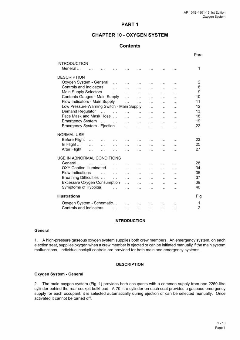
AP 101B-4901-15 1st EditionOxygen System
PART 1
CHAPTER 10 - OXYGEN SYSTEM
ContentsPara
Illustrations Fig
INTRODUCTIONGeneral… … … … … … … … … 1
DESCRIPTIONOxygen System - General … … … … … … 2Controls and Indicators … … … … … … 8Main Supply Selectors … … … … … … 9Contents Gauges - Main Supply … … … … … 10Flow Indicators - Main Supply … … … … … 11Low Pressure Warning Switch - Main Supply … … … 12Demand Regulator … … … … … … … 13Face Mask and Mask Hose … … … … … … 18Emergency System … … … … … … … 19Emergency System - Ejection … … … … … 22
NORMAL USEBefore Flight … … … … … … … … 23In Flight… … … … … … … … … 25After Flight … … … … … … … … 27
USE IN ABNORMAL CONDITIONSGeneral… … … … … … … … … 28OXY Caption Illuminated … … … … … … 34Flow Indications … … … … … … … 35Breathing Difficulties … … … … … … … 37Excessive Oxygen Consumption … … … … … 39Symptoms of Hypoxia … … … … … … 40
Oxygen System - Schematic… … … … … … 1Controls and Indicators … … … … … … 2
INTRODUCTION
General
1. A high-pressure gaseous oxygen system supplies both crew members. An emergency system, on eachejection seat, supplies oxygen when a crew member is ejected or can be initiated manually if the main systemmalfunctions. Individual cockpit controls are provided for both main and emergency systems.
DESCRIPTION
Oxygen System - General
2. The main oxygen system (Fig 1) provides both occupants with a common supply from one 2250-litrecylinder behind the rear cockpit bulkhead. A 70-litre cylinder on each seat provides a gaseous emergencysupply for each occupant; it is selected automatically during ejection or can be selected manually. Onceactivated it cannot be turned off.
1 - 10Page 1

3. A charging point for the main cylinder is on the right side of the fuselage just aft of the cockpit; a shut-offcongromaga
4.anflowprean
5.is aapgre
6.banothe
7.seamin
Nocycthe
Co
8.Fig
Ma
9.to
Co
10themaeig
Flo
11in elesysbrethemasho
1 - Pag
trol, a gauge and a captive cover are provided; there is also an overboard vent indicator to alertundcrew to main oxygen cylinder overpressure. A main system contents gauge is on the right of eachin instrument panel. Each emergency cylinder has an individual in situ charging point with a contentsuge alongside.
The main supply is routed through a combined pressure reducing valve (outlet pressure 4Q8 to 5Q8 bar)d relief valve before dividing to provide a separate supply to each cockpit. There is a shut-off valve and a
indicator transmitter for each crew position. A low pressure warning switch is in the common medium-ssure line. At the seat, the supply flows via a quick-disconnect connector, a coupled demand regulator
d a personal equipment connector (PEC) and tube to the mask.
The main oxygen supply endurance at sea level, when fully charged, with the regulator set to air mixture,pproximately 4 hours when dual and 6 hours when solo; with the regulator set to 100y, the endurance is
proximately 1 hour when dual and 1Q75 hours when solo. However, endurance, when using 100%, isater at high altitude than at low altitude.
The supply from each emergency cylinder flows through a pressure reducing valve (outlet pressure 3Q45r) to the demand regulator via the main system supply line, which it joins before reaching the regulator. An-return valve at the quick disconnect connector (para 4) prevents feedback of the emergency supply into main system.
The emergency system provides the crew with 100y oxygen during the descent of the drogue-stabilizedt(s) after ejection. The system can also be selected manually. It has an endurance of approximately 3Q5utes at low altitude and approximately 11Q5 minutes at high altitude.
te: An oxygen cylinder contains a fixed mass of oxygen. A constant volume is used for each breathingle. The pressure of the inspired oxygen (and thus the mass flow) reduces with increasing altitude. Hence endurance of the system is greater at high altitude than at low altitude.
ntrols and Indicators
The oxygen system controls and indicators, of both cockpits, are listed in Table 1 and illustrated in2.
in Supply Selectors
The main supply selectors, one on the right rear console in each cockpit, control the main oxygen supplythe seats. Each selector is ON when pointing forward and OFF when pointing athwartships.
ntents Gauges - Main Supply
. The main supply contents gauges, one on the right on the main instrument panel in each cockpit, indicate main oxygen cylinder pressure contents. The gauge scale is graduated in eighth intervals to full (F) andrked in fractions at quarterly intervals. When the gauge registers in the red sector (between zero and onehth) the oxygen main supply is to be considered empty.
w Indicators - Main Supply
. The oxygen flow magnetic indicators are electrically operated by flow transmitters in the main supply lineeach cockpit. Indicators are de-energized and show black when no oxygen is flowing or there is noctrical supply; they are energized to show white vertical bars when oxygen flows. When the main oxygentem is in use the indicators should show alternating black and white indications in time with the user'sathing. Two flow indicators are on the right on each cockpit instrument panel, one for each crew member, forward station being uppermost. At high altitude, when breathing may be shallow, the flow of oxygeny not be sufficient to operate the flow transmitter and the indicator may stay black. The crew memberuld then breathe more deeply to check the integrity of the indicator.
10e 2

AP 101B-4901-15 1st EditionOxygen System
Low Pressure Warning Switch - Main Supply
12. The main supply low pressure warnings are controlled by the low pressure warning switch, which causesthe red OXY caption to be illuminated in both cockpits when pressure is below 3Q1 to 3Q45 bar. This alsoactivates the attention getters and audio warning.
WARNING: The OXY caption gives warning of imminent failure of the main oxygen supply and does not givea particular minimum further endurance.
Demand Regulator
13. The Type 500 demand regulator is two miniature regulators in one unit which is coupled to the seatportion of the PEC. The unit provides a controlled air oxygen mixture or 100y oxygen breathing supply tothe mask at all altitudes up to 35,000 feet, and includes the following components:
a. Air/oxygen mixture section.
b. 100y oxygen section.
c. Changeover selector.
d. Press-to-test button.
14. Air/Oxygen Mixture. When the air mixture section is in use, an air/oxygen mixture is supplied to themask. The proportions of the mixture are progressively adjusted by an aneroid up to 30,000 feet; above thisaltitude 100y oxygen is delivered. The mask hose delivery pressure is adjusted by the regulator accordingto the altitude, below 15,000 feet delivering a supply to the mask at ambient pressure only when the userinhales. Above approximately 15,000 feet the mask hose delivery pressure is in excess of cockpit pressure,thus providing a safety pressure. The regulator air intake is at a low level in the cockpit and is prone to collectany fumes that gather at floor level.
15. 100y Oxygen. When the 100y oxygen section is in use, undiluted oxygen is supplied to the face maskirrespective of the aircraft altitude, and safety pressure is provided from sea level.
16. Changeover Selector. The changeover selector is used to select the required section of the regulator.The air mixture section is operative at the forward setting (AM) and the 100y section at the aft setting (100).The selector is to be set positively to its full extent of travel. When the emergency oxygen is selected on, theselector automatically changes to 100y.
17. Test Button. The test button is operative only when AM is selected. It allows the occupant to checkhis face mask for correct fit and to test the system and connections for leaks. Pressing the button increasesthe flow, and pressure at the mask confirms correct operation of the system.
Face Mask and Mask Hose
18. The oxygen face mask is connected to the helmet by a toggle chain. A bayonet connector joins the maskhose to the PEC oxygen tube which is secured to the front of the life preserver by a dog-lead clip. The PECtube is restrained at the left side of the life preserver by a flap, allowing the crew member to position the tubeto prevent elbow obstructions, and prevents flailing of the tube and PEC man-portion after man/seatseparation following an ejection.
Emergency System
19. An emergency oxygen cylinder, on the rear left side of each seat pan, has a charging point (via whichthe cylinder can be charged in situ), a contents gauge and an operating lever which is connected to manualand automatic release mechanisms on the seat. A transit safety pin can be fitted to the head of theemergency cylinder operating mechanism to prevent inadvertent operation. The pin is fitted near the headof the cylinder and its removal is to be confirmed before strapping in.
1 - 10Page 3

20. The emergency cylinder is manually selected on by pulling the seat-mounted control handle sharplyupobanem
21sysemis t
Em
22mosup
1 - Pag
wards and backwards. It may be necessary to ease the left thigh away from the control handle to preventstruction when it is being pulled. The control handle requires a pull force of between 20 and 30 lb. Once emergency supply has been selected on it cannot be turned off. There is no flow indication whenergency oxygen is being used.
. Since the outlet pressure at the emergency system valve is lower than the outlet pressure at the maintem reducing valve, emergency oxygen cannot flow if the main system pressure is dominant. If theergency supply is required in these conditions, e.g. contaminated main supply, the main supply selectoro be set to OFF.
ergency System - Ejection
. The emergency system is automatically selected on during the seat ejection sequence when an aircraft-unted striker engages the cylinder operating lever. Since the emergency system is seat-mounted, theply is lost when man/seat separation occurs.
10e 4

AP 101B-4901-15 1st EditionOxygen System
1 - 10Page 5
Oxygen System - Schematic
1 - 10 Fig 1 Oxygen System - Schematic

Controls and Indicators
OXYTEST
DAY
NIGHT
1 - 10 Fig 2 Controls and Indicators
HS/TUC/1-10-fig2/0024
1 - 10Page 6

AP 101B-4901-15 1st EditionOxygen System
Table 1 - Oxygen System Controls and Indicators
NORMAL USE
Before Flight
23. Check the system before flight in accordance with the drills in the Flight Reference Cards (FRC). Theemergency system contents gauge cannot be seen by the seated occupant, therefore, check the gaugeduring the Ejection Seat checks. The main oxygen system is not to be less than half full.
Note: Back pressures, created at the regulator by flexing of the oxygen tube or by breathing into the facemask before the oxygen supply has been selected ON, can damage valves in the regulator. Therefore, thePEC man-portion is not to be connected to the PEC seat-portion until the oxygen supply has been selectedON.
24. Testing the System. After strapping in, make the following checks independently at each crew station:
a. With Air Mixture Selected. Check that the OXY flow indicator shows white bar when breathing in
Controls/Indicators Marking LocationMain supply selector(2-position rotary control)
OXY SUPPLY - ON/OFF Right console
Main supply contents gauge OXY Right side of main instrument panelFlow magnetic indicators (two)(Main system only)
OXY FRONTOXY REAR
Right side of main instrument panel
Regulator changeover selector (2-position slide control)
AM/100 - 100 t(arrow points rearward)
On regulator (left of seat)
Test button - On regulatorEmergency supply control handle EO K
Black and yellow handleLeft side of seat pan
Emergency supply contents gauge
Two coloured segments:Green (full),Orange marked REFILL
On top of emergency supply cylinder
Oxygen supply low pressurecaption (Main system only) (red)
OXY Central warning panel (CWP)
and black when breathing out, or when holding the breath. Press the test button, check that oxygenpressure is felt at the face mask and that the flow indicator shows black/white indications during threeconsecutive breathing cycles. Release the test button. Select 100y (aft setting).
b. With 100y Selected. Check that the flow indicator responds correctly in time with crew breathing(para 24, sub-para a). Lift the mask from the face and check that the flow indicator shows a steady whitebar.
In Flight
25. The regulator may be set to AM when a positive air conditioning flow has been established after selectingBOOST following engine start. It may be selected to 100y if the air mixture regulator is suspect, faulty orwhen an emergency calls for selection of 100y oxygen (see FRC). Make periodic checks of the main oxygencontents and the operation of the flow indicators.
26. The emergency oxygen supply is of limited duration and, once activated, cannot be turned off. Restrictits use to emergency situations only.
After Flight
27. After disconnecting the PEC and before leaving the aircraft, fit the PEC seat-portion dust covers, turnOFF the oxygen in both cockpits and then select 100y on each regulator.
1 - 10Page 7

USE IN ABNORMAL CONDITIONS
Ge
28
29theind
30inddo
31uncha
32
33emma
OX
34
Flo
35selthesat10
36manoconoxy
1 - Pag
neral
. Indication of main oxygen system malfunction is given by one or more of the following:
a. Illumination of the OXY caption.
b. Flow magnetic indicator.
c. Signs of abnormal consumption.
d. Physical senses.
. The flow indicator may continue to show normal oxygen flow even when the system pressure is below minimum required by the crew. Therefore, the illuminated OXY caption is to be accepted as a trueication unless, by a process of cross-checking, it is proved to be spurious.
. Indications of a system malfunction may not appear simultaneously in both cockpits. Therefore, anyication of system failure in one cockpit should, where possible, be cross-checked with the other. A failurewnstream of a main supply selector affects the associated cockpit only.
. Malfunction of a regulator in either cockpit may occur in the air mixture or the 100y section, but islikely to occur in both sections at the same time. Therefore, in the event of a suspect regulator, set thengeover selector to the alternative setting and check the system for clearance of the failure symptoms.
. If a system malfunction (other than a red OXY caption) is indicated, check the following:
a. OXYgen SUPPLY ON.
b. PEC tube and mask hose correctly connected.
c. Contents sufficient.
d. Mask seal.
e. Alternative regulator selected.
. If emergency oxygen is selected, descend immediately below 10,000 feet, since the duration of theergency supply is limited and there are no means of monitoring the system contents or operation. If thein system pressure fails, the OXY caption is illuminated.
Y Caption Illuminated
. If the OXY caption is illuminated, select emergency oxygen and descend below 10,000 feet.
w Indications
. Steady Black. If the flow indicator shows steady black (no flow) confirm that the main system isected ON, check connections, contents and mask seal and select 100y. If breathing is then not restricted, air mixture section is at fault and flight may be continued using 100y oxygen subject to frequentisfactory checks of the contents gauge and the flow indicator. If breathing is restricted after selecting0y, select emergency oxygen and descend below 10,000 feet.
. Steady White Bar. If the flow indicator shows a steady white bar (continuous flow) confirm that thein system is selected ON, check connections, contents and mask seal and select 100y. If breathing is
t restricted the flight may be continued using 100y oxygen subject to frequent satisfactory checks of thetents gauge and the flow indicator. If breathing is restricted after selecting 100y, select emergencygen and descend below 10,000 feet.
10e 8

AP 101B-4901-15 1st EditionOxygen System
Breathing Difficulties
37. Resistance to Breathing In. If resistance to breathing in cannot be overcome by the initial checks(para 32) select emergency oxygen and descend below 10,000 feet.
38. Resistance to Breathing Out. If resistance to breathing out persists, lift the edge of the face maskfrom the face to breathe out and descend below 10,000 feet.
Excessive Oxygen Consumption
39. If the contents gauge indicates that oxygen consumption is higher than expected, check the mask andsystem connections for leaks, and descend below 10,000 feet, while oxygen endurance remains. Selecting100y may isolate a leak in the air mixture regulator. Other leaks, downstream of the main supply selector,may be isolated by setting the selector to OFF (after first selecting emergency oxygen in the associatedcockpit); this action may preserve the main supply for use in the other cockpit (when appropriate).Remember that the location of the leak may permit the escape of emergency oxygen after it has beenselected on.
Symptoms of Hypoxia
40. If symptoms of hypoxia are experienced, check the PEC and mask hose connections are made and thatthe mask is making a correct seal on the face. If the oxygen flow is not restored, select emergency oxygenand descend rapidly to below 10,000 feet. Where two crew members are present and one observessymptoms of hypoxia in the other, he is to initiate descent and encourage the other to check his oxygensystem and/or select emergency oxygen.
1 - 10Page 9

1 - Pag
Intentionally Blank
10e 10

AP 101B-4901-15 1st EditionFlight Information Displays and Instruments
PART 1
CHAPTER 11 - FLIGHT INFORMATION DISPLAYS AND INSTRUMENTS
ContentsPara
INTRODUCTIONGeneral… … … … … … … … … 1
PRESSURE - OPERATED INSTRUMENTSPitot-Static System … … … … … … … 3Main Altimeters … … … … … … … 8Standby Altimeter … … … … … … … 14Vertical Speed Indicator … … … … … … 16Combined Speed Indicator … … … … … … 17
ELECTRICALLY - OPERATED INSTRUMENTSMain Attitude Indicator … … … … … … 20Standby Attitude Indicator … … … … … … 23Turn-and-Slip Indicator … … … … … … 25
FLIGHT NAVIGATION INSTRUMENTSGyro-Magnetic Compass System … … … … … 27Horizontal Situation Indicator … … … … … 33
MISCELLANEOUS INSTRUMENTSAccelerometer … … … … … … … … 35Standby Compass … … … … … … … 36Outside Air Temperature Indicator … … … … … 37Clock … … … … … … … … … 38Stopwatch … … … … … … … … 39Angle-of-Attack Indicator and Indexer … … … … 40
ICE DETECTOR SYSTEM
NORMAL USEBefore Flight … … … … … … … … 43
Illustrations Fig
In Flight… … … … … … … … … 50
USE IN ABNORMAL CONDITIONSPower Supply Failures … … … … … … 53Pitot Static Supply Failure … … … … … … 58Instrument Covers … … … … … … … 60
Flight Information Instruments and Controls (Front Cockpit) … 1Flight Information Instruments and Controls (Rear Cockpit) … 2Pitot-Static System … … … … … … … 3Main Altimeters … … … … … … … 4Combined Speed Indicator … … … … … … 5Main Attitude Indicator … … … … … … 6Compass Controller … … … … … … … 7Horizontal Situation Indicator … … … … … 8Accelerometer … … … … … … … … 9Angle-of-Attack Indicator and Indexer … … … … 10
1 - 11Page 1 (AL 1)

INTRODUCTION
Ge
1.airveraltiindFig
No
No10for
2.in eTamaconTAby ins
Pit
3.
4.unsystail
5.
6.an
7.datra
Ma
8.an+ 3revopfeeThmisobflag
1 - Pag
neral
A primary flight instrument display, on the upper instrument panel of each cockpit, comprises a combinedspeed indicator/machmeter (CSI), a main altimeter, a main attitude indicator, a turn-and-slip indicator, atical speed indicator (VSI), and a horizontal situation indicator (HSI). Each cockpit also has a standbymeter, a standby attitude indicator, a standby magnetic compass, an outside air temperature (OAT)icator, an accelerometer, an angle-of-attack (AOA) indicator and indexer, a clock and a stopwatch (see
1 and Fig 2).
te 1: SEM 016 introduces a second stopwatch into each cockpit.
te 2: SM 109 introduces the Powerflarm Portable (FLARM) Collision Warning System. Embodiment of SM9 removes the AOA indexer from both cockpits, the AOA indicator from the front cockpit and the provision a second stopwatch in the front cockpit.
Magnetic compass heading or directional gyro heading or a combination of both is presented on the HSIach cockpit and is also fed to the Tacan. Information on ILS glidepath and localiser, VOR steering and
can range, steering and bearing can be shown on each HSI by selection at a navigation mode selector,rked VOR ILS/TACAN, in each cockpit. A HSI selector in each cockpit allows the selected track to betrolled by either the front or rear HSI track select knob. See Chapter 13 for information on the VOR ILS/
CAN and HSI selectors. Power is from the main busbar. If this supply fails, a display of attitude is providedthe standby attitude indicator and the standby magnetic compass gives direction information. Fortrument lighting refer to Chapter 12, or to the relevant paragraph in this chapter.
PRESSURE - OPERATED INSTRUMENTS
ot-Static System
Pitot and static air pressures are fed to pressure instruments in the front and rear cockpits (see Fig 3).
The pitot tube under the left wing and two static ports supply the front cockpit instruments. The pitot tubeder the right wing and two other static ports supply the rear cockpit instruments. One static port of eachtem is on the horizontal centreline on each side of the fuselage between the avionics bay and theplane. This compensates for sideslip, giving an average of the pressures sensed by the static ports.
For ice protection see Chapter 14.
The pitot-static system supplies the main altimeters (repeater in rear cockpit), standby altimeters, VSId CSI.
Tappings from the pitot and static lines provide inputs to height and speed transducers in the accidentta recorder. A further tapping from the pitot line provides an input to an airspeed and ambient staticnsducer for the engine (see Chapter 4).
in Altimeters
A Mk 30C servo encoding altimeter (Fig 4) in the front cockpit gives indications of altitude on a counterd by a single pointer. The altimeter, which uses static pressure, has a calibrated range of minus 1000 to5,000 feet and provides an encoded altitude, for altitude reporting, and a synchro signal to drive a pressureersion repeater altimeter Mk 29C (Fig 4) in the rear cockpit. When not being servo driven the Mk 29C
erates as a sensitive altimeter. On both altimeters the pointer makes one full rotation for each thousandt of altitude. Each altimeter has a 3-drum 5-digit counter which indicates altitude in increments of 100 feet.e window displaying hundreds of feet is elongated to display three digits simultaneously to avoidinterpretation. Between zero and 9900 feet, the tens of thousands of feet digit (left-hand drum) is
scured by a black and white striped flag; below zero feet, the digit is obscured by a red-and-white striped. Altitude below zero feet is calculated by adding the indicated height to minus 10,000 feet, e.g. a true
11e 2

AP 101B-4901-15 1st EditionFlight Information Displays and Instruments
pressure altitude of minus 200 feet is indicated when the red and white flag obscures the tens of thousandsof feet digit and the altimeter display reads 9800 feet (minus 10,000 feet + 9800 feet).
9. Altimeter Pressure Datum. Both the Mk 30C and Mk 29C altimeters have a pressure datum settingcontrol, at the lower left hand corner, for adjusting the hectopascal sub-scale in the face of the instrument.The controls on the front and rear cockpit altimeters are not interconnected.
10. Altimeter Coded Output. The front cockpit altimeter gives a digitized coded output of altitude to thetransponder. The coded output is related to 1013Q25 mb and is not affected by changing the setting of thehectopascal sub-scale.
11. Altimeter Dial Presentation. The dial is calibrated in steps of 100 feet with subdivisions at 50 feetintervals. The Mk 29C altimeter has a flag, marked STBY, that indicates when the altimeter is not acting asa repeater of the Mk 30C altimeter. Flight Information Instruments and Controls (Front Cockpit)
ANGLE OF ATTACKINDICATOR AND INDEXER
TURN AND SLIPINDICATOR
STOPWATCH ACCELEROMETER
STANDBYALTIMETER
STANDBYCOMPASS
SERVO ENCODINGALTIMETER
VSI
OAT GAUGE
COMPASSCONTROLLER
STANDBY ATTITUDEINDICATOR
MAIN ATTITUDEINDICATOR
CLOCK
CSI
TCAS
HSI
COMPASS
SEL
MARKERHSI
SEL
VOR ILS
TACAN
1 - 11 Fig 1 Flight Information Instruments and Controls (Front Cockpit)
HS/TUC/15-1-11-fig1/0534
1 - 11Page 3 (AL 1)

Flight Information Instruments and Controls (Rear Cockpit)
ST
COM
S
1 - Pag
ANGLE OF ATTACKINDICATOR AND INDEXER
TURN AND SLIPINDICATOR
STOPWATCH ACCELEROMETER
STANDBYALTIMETER
STANDBYCOMPASS
SERVOALTIMETER
VSI
OAT GAUGE
COMPASSCONTROLLER
ANDBY ATTITUDE
MAIN ATTITUDEINDICATOR
CSI
TCAS
HSI
PASS
EL
MARKERHSI
SEL
VOR ILS
TACAN
INDICATOR
1 - 11 Fig 2 Flight Information Instruments and Controls (Rear Cockpit)
HS/TUC/15-1-11-fig2/0535
11e 4

AP 101B-4901-15 1st EditionFlight Information Displays and Instruments
Pitot-Static System
1 - 11 Fig 3 Pitot-Static System Main Altimeters
1 - 11 Fig 4 Main Altimeters Combined Speed Indicator
1 - 11 Fig 5 Combined Speed Indicator
1 - 11Page 5

12. Mk 29C Altimeter Standby/Reset. A centrally biased selection switch, marked STBY/RESET, is on thebo
13is couthe
Sta
14by regmoinc
15a bviesub
Ve
16to
Co
17AirMa0Q7ma
18the
1 - Pag
ttom right hand corner of the Mk 29C altimeter and operates as follows:
a. Standby Mode. If the altimeter is tripped into the standby mode either manually, or automaticallyby a fail-safe detection circuit, the STBY flag drops into view on the dial face. At the same time anintegral vibrator is energized to overcome friction and minimize error. Reversion to servo operation isby manual reselection of RESET provided that the cause of the failure is no longer present. WhenRESET is selected the STBY flag disappears and the vibrator is de-energized. The detection circuitautomatically reverts the altimeter to the mechanical standby mode in the event of any of the followingfaults:
(1) Primary power failure.
(2) Servo amplifier failure.
(3) Servo motor failure.
(4) Failure within any part of the detection circuit.
(5) Servo failure of the Mk 30C altimeter.
(6) Differences (at MSL) of greater than 4000 feet between the standby and servo indicatedaltitude.
b. Servo Mode. The altimeter is engaged in the servo mode by selecting RESET. The altimeter nowacts as a repeater of the Mk 30C altimeter.
. Altimeter Power Supplies. Both altimeters are supplied from the 115V AC busbar. The Mk 29C vibratorsupplied from the load shedding busbar. If the AC power fails, or the servo malfunctions, the altitudenter of the Mk 30C is obscured by a red-and-black striped bar and the Mk 29C automatically operates in STBY mode.
ndby Altimeter
. A Mk 28E standby altimeter in each cockpit gives indications of altitude on a 2-drum 4-digit counter anda pointer. The pointer makes one revolution for each 1000 feet change of altitude and the 4-digit counteristers the whole number of thousands and tens of thousands of feet. To ensure a smooth pointervement throughout the range an internal vibrator, supplied from the essential services busbar, isorporated. A hectopascal setting control is at the lower left corner of the instrument.
. Dial Presentation. The dial presentation comprises a pointer and a 4-digit counter displaying altitude,arometric sub-scale and a flag, marked VIB, to indicate the vibrator condition. The VIB flag goes out of
w when power is applied to the standby altimeter. The dial is calibrated in steps of 100 feet withdivisions at 50 feet intervals.
rtical Speed Indicator
. A VSI in each cockpit is calibrated in thousands of feet per minute and registers rate of climb and descenta maximum of 6000 feet per minute.
mbined Speed Indicator
. A CSI (Fig 5) in each cockpit shows airspeed and Mach number derived from pitot and static pressure.speed is indicated by a pointer against a scale graduated from 50 to 350 knots in 10 knots increments.ch number is shown in a window and read against the airspeed pointer; the scale is calibrated from 0Q3 toM in increments of 0Q02M. The Mach number scale moves independently of the airspeed pointer tointain the correct relationship between airspeed and Mach number.
. An adjustable fluorescent orange airspeed lubber mark, with 360 degrees of rotation, is set by a knob at lower left of the instrument.
11e 6

AP 101B-4901-15 1st EditionFlight Information Displays and Instruments
19. The instrument has two airspeed switches set at 290 knots and 100 knots to activate overspeed and U/C warnings respectively.
ELECTRICALLY - OPERATED INSTRUMENTS
Main Attitude Indicator
20. The main attitude indicator (Fig 6) in each cockpit is of the moving ball type, and has an integral verticalgyro assembly powered by an integral static inverter. The gyro assembly provides the pitch and roll signalfor the indications on the moving ball. The moving ball has a blue top half with white pitch attitude markings,representing the area above the horizon, and a brown bottom half with white pitch attitude markingsrepresenting the area below the horizon; a white line between the two halves represents the horizon. Pitchattitude is indicated by division lines marked at 5L intervals on both halves of the ball parallel to the horizonline, and read against a fixed black/fluorescent orange aircraft symbol. The division lines are numbered 1 to8 from the horizon line to show 10L to 80L of climb or dive. Roll attitude in each direction is measured bymovement of an index against a fixed semicircular scale which has 30L divisions up to 90L and 10Lsubdivisions to show bank angles up to 30L; the fixed scale, marked in white, is at the bottom of the indicatordisplay. A fast erection knob is at the bottom right of the instrument. A red-and-black striped warning flag atthe top of the display indicates a power supply failure, when the gyro is running below 18,000 RPM or thefast erection knob is pulled. Main Attitude Indicator
1 - 11 Fig 6 Main Attitude Indicator
21. Fast Erection Knob. Pulling the fast erection knob brings the integral gyro assembly near the vertical;when the knob is released the gyro is free to move and aligns itself precisely with the true vertical. To ensurethat the gyro has attained a sufficiently high rotation speed before fast erection is initiated, wait for a minimumof 30 seconds after application of power before pulling the fast erection knob. Thereafter only use the knobin straight, level and balanced flight.
Note: Unrestrained release of the fast erection knob may damage the instrument internally; therefore,manually restrain the return spring action when releasing the knob.
22. Power Supplies. The main attitude indicator has an integral static inverter, which provides AC to drivean integral gyro assembly. The inverter is powered from the main busbar. If the power supply fails a red andblack striped flag is displayed centrally at the top of the instrument face. After applying power the gyrorequires three minutes to spin up to its operating speed; the instrument should not be used within this period.
Standby Attitude Indicator
23. A standby attitude indicator in each cockpit is smaller than the main attitude indicator. It is similar inappearance (except that the red-and-black striped warning flag appears slightly to the right at the top of the
1 - 11Page 7

instrument face) and presents information in the same way as the main attitude indicator. Fast erectionpro
24dri
Tu
25baindinte
26fro
Gy
27attancomalsallo
28ontheof to to trattheexc
29Elene
30
1 - Pag
cedure is also similar to that for the main attitude indicator.
. Power Supplies. The standby attitude indicator has an integral static inverter, which provides AC tove an integral gyro assembly. The inverter is powered from the essential services busbar.
rn-and-Slip Indicator
. A turn-and-slip indicator in each cockpit has a pointer, which indicates direction and rate of turn, and all which indicates slip or skid. The rate scale is graduated, left and right of a centre-mark, with marks toicate rate 1 and rate 2 turns. An orange-and-black striped warning flag appears when the DC supply isrrupted or the integral gyro RPM drop to a level where accuracy is impaired.
. Power Supplies. An integral static inverter provides AC to the integral gyro assembly, and is poweredm the essential services busbar.
FLIGHT NAVIGATION INSTRUMENTS
ro-Magnetic Compass System
. The DG710A gyro-magnetic compass system consists of a gyro unit (with a compensation moduleached) in the avionics equipment bay, a compass controller on the lower instrument panel in each cockpitd a flux detector unit in the tail fin. Magnetic compass information or directional gyro information or a
bination of both from the gyro-magnetic compass system is presented on the HSI in each cockpit, and iso fed to the Tacan. A selector, marked COMPASS/SEL, on the lower instrument panel of each cockpit,ws control of the compass system from either cockpit.
. Gyro Unit. The gyro unit contains a directional gyro which provides a stable reference. On initial switch- the gyro executes a self test sequence, which can be monitored by reference to the HSI. The accuracy of displayed heading is within m1Q5L and is valid within two minutes of system switch-on; the heading flagseach HSI then clear. A normal erection/slaving system levels the gyro at 5 m 2L per minute and slaves itthe detector unit heading at 2Q25 m 0Q5L per minute. The gyro unit can be fast erected and/or fast slavedhe detector unit heading, using the FAST ERECT button on the compass control panel. The fast erectione is not less than 300L per minute, and the fast slaving rate is 8L per second for 0 to 3 seconds andreafter 30L per second. An automatic erection/slaving cut-out circuit operates when the rate of turneeds 30L per minute.
. Compensation Module. The compensation module interfaces with the gyro unit and containsctrically Erasable Programmable Read Only Memory (EPROM). This memory contains the data
cessary to eliminate index error, single cycle error and instrument error.
. Compass Controller. The compass controller (Fig 7) has the following features:
a. Mode Selector. The mode selector is a 3-position gated switch which is used to select gyrooperating mode. It is necessary to lift the switch out of SLAVE mode to either DG or COMPASS mode.The gyro operating modes are as follows:
(1) SLAVE Mode. Heading output derived from flux detector unit with gyro stabilization.
(2) DG Mode. Heading output derived from gyro motion only.
(3) COMPASS Mode. Heading output derived from flux detector unit only.
11e 8

AP 101B-4901-15 1st EditionFlight Information Displays and Instruments
Compass Controller
1 - 11 Fig 7 Compass Controller
b. SLEW Control. The SLEW control is a 3-position, centre off, spring-loaded switch. When the modeselector is at DG the switch applies the appropriate signal to the gyro unit which in turn drives the headingoutput in a clockwise (CW) or counter-clockwise (CCW) direction.
c. FAST ERECT Button. The FAST ERECT button is used to synchronize the gyro and level the innergimbal axis rapidly to the case horizontal.
d. Slaving Annunciator. The slaving annunciator has a centre zero movement with a pointer whichmoves left (-) or right (+) of centre to indicate the direction in which the gyro is desynchronized; a fullscale deflection indicates an error of 10L or more. If the pointer is deflected, resynchronize the compassby pressing and releasing FAST ERECT.
31. Flux Detector Unit. The flux detector unit provides long-term heading information by sensing thehorizontal component of the earth's magnetic field.
32. Power Supplies. Power is from the main busbar. The compass controllers have 5V AC integral lighting,which is controlled by the INSTRUMENTS dimmer in the respective cockpit.
Horizontal Situation Indicator
33. An Horizontal Situation Indicator (HSI) (Fig 8) on the upper instrument panel of each cockpit combinesthe compass system, the VOR/ILS and the Tacan displays. A selector, marked HSI/SEL, on the upperinstrument panel of each cockpit allows the selected track to be determined either by the front cockpit HSI orby the rear cockpit HSI, when the respective selector indicates SEL. The HSI displays the following:
a. Heading. Heading is indicated by a fixed orange lubber line above a rotating compass card. Thecard is graduated at 5L intervals and is marked alpha numerically at 30L intervals.
b. Heading Select Marker. A green heading select marker registers against the outside edge of, androtates with, the compass card. The marker can be manually set relative to the compass card by aheading select knob, annotated HDG and marked with a symbol representing the heading select marker,at the lower left of the instrument.
c. Selected Track Pointer and Digital Track Read-out. A yellow selected track pointer registersagainst, and rotates with, the compass card. The pointer can be manually set relative to the compasscard by a track select knob, annotated CRS and marked with a symbol representing the selected trackpointer, at the lower right of the instrument. The reciprocal of the track set is indicated by a selectedtrack pointer tail which registers against, and rotates with, the compass card. A 3-digit display of theselection is given on a digital track read-out (COURSE) at the top right.
1 - 11Page 9

Horizontal Situation Indicator
1 - Pag
1 - 11 Fig 8 Horizontal Situation Indicator
d. Track Deviation Bar. A yellow track deviation bar, and a fixed scale of four white dots either sideof a centre index, are in the centre display assembly. The outer edge of the centre index represents thefirst dot of the scale. The bar moves left or right of the index to indicate deviation (2L per dot) from theselected track when a Tacan or VOR is selected, or 0Q5L per dot from an ILS localiser when ILS isselected.
e. Bearing Pointer. The magnetic bearing to a Tacan ground beacon, is indicated by a magenta
pointer head when read against the compass card; VOR bearing is indicated by a pale blue pointer head.The reciprocal bearings (or radials) are indicated by the tail of the appropriate pointer. Provided that theTacan and VOR remain locked to a ground beacon, their respective bearings are displayed continuouslyirrespective of navigation mode selection.
f. To/From Indicator. The to/from indicator is a white triangle, and appears underneath the trackdeviation bar on the centre display assembly. With the navigation mode selector set to TACAN, a Tacanradial set on the selected track pointer, and the Tacan locked onto a Tacan beacon, the white triangle isdisplayed either `to' or `from'. Whenever the bearing from the Tacan beacon is less than 90L from theselected Tacan radial, a `to' indication is displayed. Conversely, whenever the bearing from the Tacanbeacon is more than 90L from the selected Tacan radial, a `from' indication is displayed. Similarindications are displayed when the navigation mode selector is set to VOR ILS and a VOR selection ismade.
g. Digital Distance Read-out. Slant range to a Tacan ground beacon, in nautical miles, is shown ona 4-digit read-out, marked MILES, at the upper left corner of the instrument. When range information isinvalid the read-out indicates four dashes. Provided Tacan is locked to a ground beacon, range isdisplayed irrespective of navigation mode selection.
11e 10
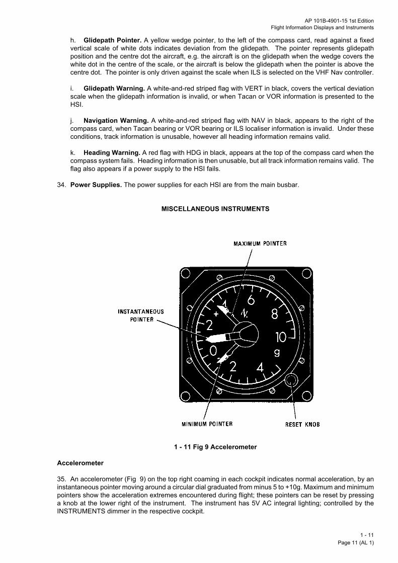
AP 101B-4901-15 1st EditionFlight Information Displays and Instruments
h. Glidepath Pointer. A yellow wedge pointer, to the left of the compass card, read against a fixedvertical scale of white dots indicates deviation from the glidepath. The pointer represents glidepathposition and the centre dot the aircraft, e.g. the aircraft is on the glidepath when the wedge covers thewhite dot in the centre of the scale, or the aircraft is below the glidepath when the pointer is above thecentre dot. The pointer is only driven against the scale when ILS is selected on the VHF Nav controller.
i. Glidepath Warning. A white-and-red striped flag with VERT in black, covers the vertical deviationscale when the glidepath information is invalid, or when Tacan or VOR information is presented to theHSI.
j. Navigation Warning. A white-and-red striped flag with NAV in black, appears to the right of thecompass card, when Tacan bearing or VOR bearing or ILS localiser information is invalid. Under theseconditions, track information is unusable, however all heading information remains valid.
k. Heading Warning. A red flag with HDG in black, appears at the top of the compass card when thecompass system fails. Heading information is then unusable, but all track information remains valid. Theflag also appears if a power supply to the HSI fails.
34. Power Supplies. The power supplies for each HSI are from the main busbar.
MISCELLANEOUS INSTRUMENTS Accelerometer
1 - 11 Fig 9 Accelerometer
Accelerometer
35. An accelerometer (Fig 9) on the top right coaming in each cockpit indicates normal acceleration, by aninstantaneous pointer moving around a circular dial graduated from minus 5 to +10g. Maximum and minimumpointers show the acceleration extremes encountered during flight; these pointers can be reset by pressinga knob at the lower right of the instrument. The instrument has 5V AC integral lighting; controlled by theINSTRUMENTS dimmer in the respective cockpit.
1 - 11Page 11 (AL 1)

Standby Compass
36unthevar
Ou
37con65accfroins
Nococma
Clo
38adrot
Sto
39is ma s
An Angle-of-Attack Indicator and Indexer
Nothe
40cocis cleaele
1 - Pag
. A standby compass on the right coaming, behind the mirror in each cockpit, is a self-contained magneticit that provides a constant indication of aircraft heading. The compass has integral lighting controlled by INSTRUMENTS dimmer switch, and is supplied from the essential services busbar; intensity is notiable.
tside Air Temperature Indicator
. A master OAT indicator in the front cockpit, and a slave OAT indicator in the rear cockpit, provide atinuous reading of outside air temperature. The scale of the indicator is calibrated over the range minus
L to +85LC. The indicated temperature reading is only accurate when stationary. When airborne theuracy is affected by altitude and speed. Correction figures for all heights and speeds can be obtained
m the IOAT/OAT conversion graph in AP101B-4901-16, the Tucano T Mk1 Operating Data Manual. Thetrument has 5V AC integral lighting controlled by the INSTRUMENTS dimmer in the respective cockpit.
te: Calibration tolerances of m3LC can cause a difference of up to 6LC between the readings in the twokpits. Also the system tends to overread by up to 3LC. Due to gauge tolerances and incrementalrkings the instrument does not indicate temperature sufficiently precisely to judge the onset of icing.
ck
. A clock on the left instrument panel in the front cockpit displays actual time in hours and minutes. Twoditional hands controlled by a reset knob display elapsed minutes and seconds on the same face. Aatable bezel, marked in minutes, is controlled by a small knob.
pwatch
. Each cockpit has a stopwatch mounted on the glareshield. If SEM 016 is embodied, a second stopwatchounted adjacent to the first in each cockpit. However, with SM 109 (FLARM) embodied, SEM 016 adds
topwatch to the rear cockpit only.
gle-of-Attack Indicator and Indexer
1 - 11 Fig 10 Angle-of-Attack Indicator and Indexer
te: Embodiment of SM 109 (FLARM) removes the AOA indexer from both cockpits, the AOA indicator from front cockpit and the provision for a second stopwatch in the front cockpit.
. The AOA indicator and indexer (Fig 10) are adjacent to each other on the top left coaming in eachkpit. The AOA indicator displays AOA from minus 10 to +25 units and the calibrated pointer movementlockwise from a red-coloured OFF position to minus 10 units. The integrally heated AOA sensor on theding edge of the left wing provides signals via the AOA electronics unit to the AOA indicator. The AOActronics unit is powered from the essential services busbar. The indicator has 5V AC integral lighting
11e 12
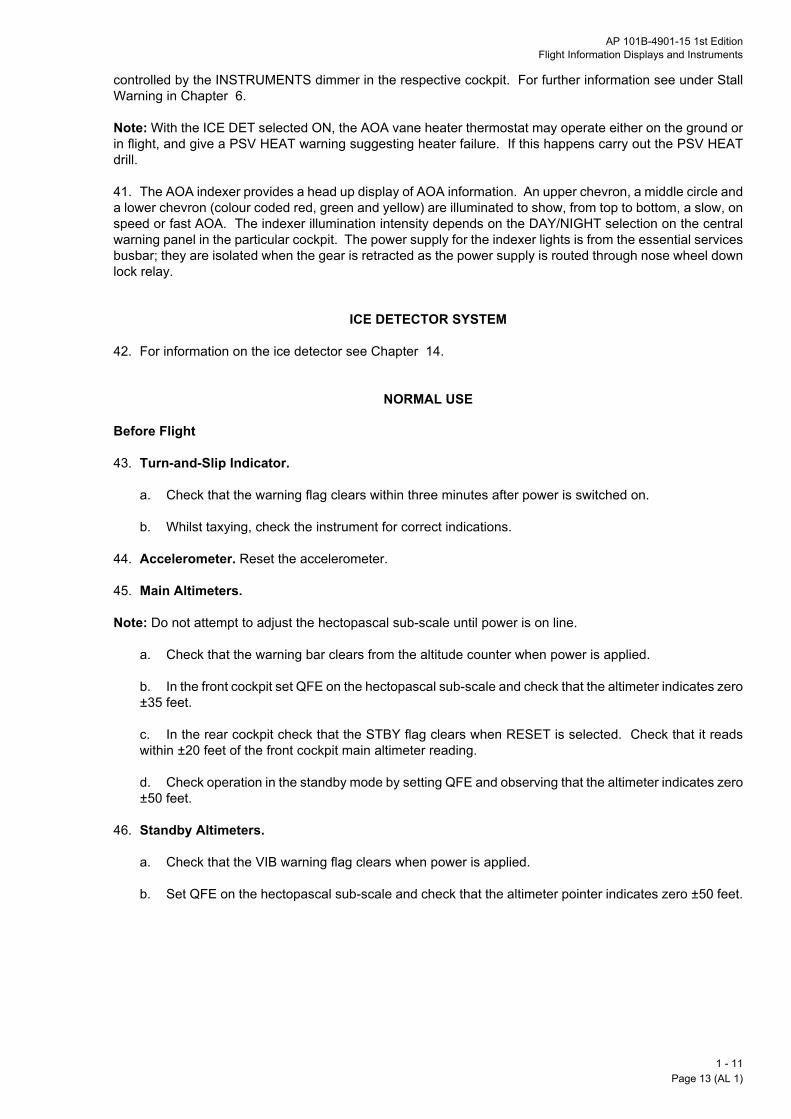
AP 101B-4901-15 1st EditionFlight Information Displays and Instruments
controlled by the INSTRUMENTS dimmer in the respective cockpit. For further information see under StallWarning in Chapter 6.
Note: With the ICE DET selected ON, the AOA vane heater thermostat may operate either on the ground orin flight, and give a PSV HEAT warning suggesting heater failure. If this happens carry out the PSV HEATdrill.
41. The AOA indexer provides a head up display of AOA information. An upper chevron, a middle circle anda lower chevron (colour coded red, green and yellow) are illuminated to show, from top to bottom, a slow, onspeed or fast AOA. The indexer illumination intensity depends on the DAY/NIGHT selection on the centralwarning panel in the particular cockpit. The power supply for the indexer lights is from the essential servicesbusbar; they are isolated when the gear is retracted as the power supply is routed through nose wheel downlock relay.
ICE DETECTOR SYSTEM
42. For information on the ice detector see Chapter 14.
NORMAL USE
Before Flight
43. Turn-and-Slip Indicator.
a. Check that the warning flag clears within three minutes after power is switched on.
b. Whilst taxying, check the instrument for correct indications.
44. Accelerometer. Reset the accelerometer.
45. Main Altimeters.
Note: Do not attempt to adjust the hectopascal sub-scale until power is on line.
a. Check that the warning bar clears from the altitude counter when power is applied.
b. In the front cockpit set QFE on the hectopascal sub-scale and check that the altimeter indicates zerom35 feet.
c. In the rear cockpit check that the STBY flag clears when RESET is selected. Check that it readswithin m20 feet of the front cockpit main altimeter reading.
d. Check operation in the standby mode by setting QFE and observing that the altimeter indicates zerom50 feet.
46. Standby Altimeters.
a. Check that the VIB warning flag clears when power is applied.
b. Set QFE on the hectopascal sub-scale and check that the altimeter pointer indicates zero m50 feet.
1 - 11Page 13 (AL 1)

47. Attitude Indicators.
48
49Se
Nofro
In
50
51ressynan
52CS
1 - Pag
a. If necessary operate the fast erect system but not within 30 seconds of switch on.
b. Check that the warning flags clear.
. Gyro-Magnetic Compass and HSI.
a. Set the compass mode selector to SLAVE.
b. Check that the HDG warning flag clears from the HSI.
c. Check the HSI compass heading against the standby compass.
d. Using the heading select knob (HDG) on the HSI, check that the heading select marker moves freelyrelative to the compass card.
e. Set HDG as required.
f. Select control of the HSI.
g. Using the track select knob (CRS) on the HSI, check that the selected track pointer moves freelyrelative to the compass card and that the digital track (COURSE) counters indicate correctly.
h. Set track as required.
. AOA and Ice Detector Ground Tests. Test the AOA indicator and indexer and the ice detector system.e Chapter 6 and Chapter 14 respectively.
te: Embodiment of SM 109 (FLARM) removes the AOA indexer from both cockpits and the AOA indicatorm the front cockpit.
Flight
. Attitude Indicators. After aerobatics or spinning the attitude indicators may need to be re-erected:
a. Establish straight level and balanced flight.
b. Pull the fast erect knobs until the attitude is correctly indicated.
c. Release the fast erect knobs.
. Gyro-Magnetic Compass. Gimbal error, in turns with more than 45L bank, may cause difficulty andult in roll-out heading errors in excess of 10L. Periodically check that the gyro-magnetic compass remainschronized. In particular it is recommended that the compass be fast-erected and resynchronized after
y aerobatics whether or not it appears to indicate that it is synchronized. If synchronization is necessary:
a. Establish straight level balanced flight.
b. Press and release the compass system FAST ERECT button.
c. When the HDG warning flag clears check the HSI compass heading against the standby compass.
. Angle-of-Attack Indicator and Indexer. A cross-check of the AOA system can be made against theI at an AUM of 2650 m 50 kg with 20% torque:
a. At 120 m 4 knots with landing gear and flaps up the AOA should be minus 7 units.
b. At 90 m 3 knots with landing gear and flaps down the AOA should be zero.
11e 14

AP 101B-4901-15 1st EditionFlight Information Displays and Instruments
c. The AOA indexer indicates a fast chevron (yellow) whenever the landing gear is down unless theIAS is below 90 m 3 knots.
d. With landing gear and flaps down the AOA indexer indicates an on speed circle (green) at 10 unitsAOA at 77 m 3 knots and a slow chevron (red) at 14 units AOA at 69 m 2 knots.
Note 1: The above values are only true for an AUM of 2650 m 50 kg.
Note 2: Embodiment of SM 109 (FLARM) removes the AOA indexer from both cockpits and the AOAindicator from the front cockpit.
USE IN ABNORMAL CONDITIONS
Power Supply Failures
53. Main Altimeters. If the power supply to the main altimeter in the front cockpit fails, the warning barobscures the altitude counter, and the main altimeter in the rear cockpit reverts to its standby mode. Theheight encoding to the transponder also fails.
54. Standby Altimeters. If the power supply to a standby altimeter fails the red VIB flag appears; thealtimeter indications are then prone to lag and stiction but may still be used.
55. Attitude Indicators. If the power supply to the main attitude indicator fails, use the standby attitudeindicator. If the main attitude indicator information is unreliable (cross-checked against the standby attitudeindicator and performance instruments) and the main attitude indicator warning flag is not displayed, achievestraight level balanced flight, and then pull and hold the fast erect knob until the display is erected. Releasethe fast erect knob and monitor the performance of the main attitude indicator against the standby attitudeindicator and performance instruments.
56. HSI. If the HDG flag appears on the HSI the heading information cannot be used. Heading informationmay be regained by selecting one of the reversionary modes:
a. Compass Mode. Select the mode selector on the compass control panel to COMPASS. Thedisplayed heading is subject to normal unstabilized magnetic compass errors, but in straightunaccelerated flight, a reasonably accurate heading is shown.
b. DG Mode. Select the mode selector on the compass control panel to DG and, using the SLEW
control, slew the gyro unit heading to a heading obtained from either the HSI with the mode selector toCOMPASS, or from the standby compass. If these headings differ by more than 15L when in straightlevel balanced flight, use the standby compass heading. If, with DG selected, the heading wanders, thegyro unit is unserviceable; use the COMPASS mode.
57. Turn-and-Slip Indicator. If the warning flag is displayed on the turn indicator the turn indications areunreliable and are not to be used; the slip ball indications are unaffected.
Pitot Static Supply Failure
58. Combined Speed Indicators. If either or both CSI malfunction a cross-check may be made against theAOA information. If the airspeed indication fails, a circuit can be flown lowering the landing gear and flaps toMID downwind at minus 7 units AOA and then flying a final approach at zero units AOA, which givesapproximately 90 m 3 knots (see para 52 and Part 4, Chapter 2, para 19.)
59. Altimeters. If one pitot static supply fails, one main and one standby altimeter malfunction in oppositecockpits. Use the standby altimeter in the cockpit that has the main altimeter failure.
Instrument Covers
60. Cloth covers for both main and standby attitude indicators are attached to the underside of the glareshields in both cockpits by velcro fasteners. If any of these instruments fail, the covers may be used to
1 - 11Page 15 (AL 1)

remove false, distracting indications from view by attaching the covers to the velcro fastenings around theins
1 - Pag
truments.
11e 16

AP 101B-4901-15 1st EditionGeneral Equipment
PART 1
CHAPTER 12 - GENERAL EQUIPMENT
ContentsPara
Illustrations Fig
INTRODUCTION
General
1. This chapter covers aircraft lighting, the accident data recorder and details of equipment stowages forloose items. Aircraft picketing points are also identified.
DESCRIPTION
Interior Lighting
2. General. The aircraft interior lighting (Fig 1) is independently controlled for each cockpit. The facilitiesprovided are panel and instrument lighting, background lighting, map reading lights, emergency cockpitlighting and a utility lamp. The baggage compartment has a remotely controlled lamp.
INTRODUCTION General… … … … … … … … … 1
DESCRIPTIONInterior Lighting … … … … … … … 2Exterior Lighting … … … … … … … 10Accident Data Recorder … … … … … … 15Equipment Stowages … … … … … … … 21Miscellaneous Equipment … … … … … … 25
Interior Lighting Controls … … … … … … 1Miscellaneous Equipment Stowage and Location… … … 2
3. Panel and Instrument Lighting. Instruments and control units on the main instrument panel areintegrally lit. A pillar lamp on the right upper side of the panel illuminates the oxygen flow indicators. Theside consoles and lower instrument panels have electro-luminescent panels. Selection is made using theNORMAL - ON/OFF switch on the INTERIOR LIGHTS section (see Table 1) of the related main instrumentpanel. Lighting intensity is controlled by two dimmers (PANELS and INSTRUMENTS); these are above thecontrol switch. Background lighting, the map reading lights, the standby compass and the U/VHF control unitare illuminated from the essential services busbar when the INSTRUMENTS dimmer switch is selected on;the intensity is not variable. All other panel and instrument lighting is powered from the AC busbar.
4. Background Lighting. Each cockpit has four red background lamps, two above each side console.They are controlled by switching on the INSTRUMENTS dimmer switch on the INTERIOR LIGHTS section(see Table 1) of the main instrument panel; the intensity is not variable. Power is from the essential servicesbusbar via circuit breakers 62 and 63. The forward left light may be rotated into the cockpit to serve as a lightfor the left knee pad.
5. Map Reading Lights. Each cockpit has two map reading lights, located on the left and right undersideof the coaming. They are controlled by switching on the INSTRUMENTS dimmer switch on the INTERIORLIGHTS section (see Table 1) of the main instrument panel; the intensity is not variable. Power is from theessential services busbar via circuit breakers 62 and 63. Integral switches allow the lights to be operatedindependently on/off by pulling/pushing the lens cap.
1 - 12Page 1

6. Emergency Cockpit Lamps. Each cockpit has four floodlights, two above each side console. It isimpThTais ffor
7.conwid10ga
8.sw
InIn
Ro
Ro
Emsw
Utco
ExNa
An
La
Ta
1 - Pag
ortant to ensure before every flight that they are set up correctly and pointing at the instrument panel.ey are controlled by a 3-position switch EMERG - OFF/DIM/BRT on the INTERIOR LIGHTS section (see ble 1) of the main instrument panel; above the switch is a beta strip to aid identification in the dark. Powerrom the essential services busbar; two circuit breakers labelled EMGY LTG - FRONT, REAR are on theward panel of circuit breakers on the right in the front cockpit.
Table 1 - Interior and Exterior Lighting Controls
Control Marking Functionterior Lights (Both Cockpits)struments/Panel light switch NORM - ON-OFF Controls supply from AC busbar dimmer
controls for instrument and panel lightingtary dimmer PANELS Controls intensity of electro-luminescent
panel lightingtary dimmer INSTRUMENTS Controls intensity of integral lighting. Selects
standby compass and U/VHF panel lighting, background lighting and map reading lights respectively; the intensity of these is not variable
ergency cockpit lamps itch
EMERG - OFF/DIM/BRT Beta strip above the switch
Controls supply from essential services busbar to four floodlights, two each side of the cockpit
ility lamp (integrally ntrolled)
Unmarked Provides an additional map reading or instrument illumination facility. Power is from the main busbar
terior Lights (Front Cockpit only)vigation lights switch NAV - OFF/DIM/BRIGHT Controls supply from main busbar to
navigation lightsti-collision lights switch STROBES - ON-OFF Controls supply from load shedding busbar to
strobe lightsnding lamps switch LANDING - ON/OFF Energizes a contactor using power from the
main busbar to connect operating power from the load shedding busbar to two landing lamps
xy lamp switch TAXI - OFF/TAXI/AUTO Selects the lamp on the nose gear leg using operating power from the load shedding busbar when:
Utility Lamps. A utility lamp is provided in each cockpit. The lamps are at the forward end of the rightsole in both cockpits. Integral controls allow selection of white or red floodlighting in narrow or wide beamths. The lamps are removable for map reading and are powered from the main busbar via circuit breakers
8 and 109. In the stowed position, and at a reasonably low intensity, the lamps can be pointed at the fueluge area to enhance the readability of the gauge or the visibility of the fuel pump switches.
Baggage Compartment Lamp. The baggage compartment has a single lamp and associated ON/OFFitch on the roof of the compartment. The lamp is powered from the main busbar via circuit breaker 109.
(a) Switch is set to TAXI for ground use. Controlling power is taken from the main busbar
(b) Switch is set to AUTO in flight. Taxy lamp illuminates when landing gear is down. Controlling power is taken from the essential services busbar
12e 2

AP 101B-4901-15 1st EditionGeneral Equipment
9. Reflections. The main instrument panel and console and background lighting together give strongreflections on the inside of the canopy thus compromising night vision adaptation and the ability to lookout.There is a heightened risk of disorientation caused by apparent movement of these reflections as the pilot'shead is moved. Interior Lighting Controls
1 - 12 Fig 1 Interior Lighting Controls
1 - 12Page 3

Miscellaneous Equipment Stowage and Location
1 - Pag
1 - 12 Fig 2 Miscellaneous Equipment Stowage and Location
12e 4

AP 101B-4901-15 1st EditionGeneral Equipment
Exterior Lighting
10. General. The aircraft exterior lighting consists of two landing lamps, a taxy lamp, three navigation lightsand three anti-collision lights. All exterior lighting is controlled from the front cockpit only.
11. Navigation Lights. Navigation lights, together with anti-collision lights as combined units, are in theleading edge of the left and right wing tips; a separate navigation light is in the rudder lower fairing. Thenavigation lights are controlled by a 3-position NAV - OFF/DIM/BRIGHT switch on the EXTERIOR LIGHTINGpanel on the front cockpit left console. Power is from the main busbar via circuit breaker 107.
12. Anti-Collision Lights. White strobe anti-collision lights are with the navigation lights in the leading edgeof the left and right wing tips; a separate anti-collision light is in the rudder lower fairing. They are controlledby a 2-position STROBES - ON/OFF switch on the EXTERIOR LIGHTING panel. Power is from the loadshedding busbar via circuit breaker 70.
13. Landing Lamps. A 450-watt landing lamp is in each wing leading edge. Both lamps are controlled byone 2-position LANDING - ON/OFF switch on the EXTERIOR LIGHTING panel. Control power supplies aretaken from the main busbar via circuit breaker 106 and filaments are supplied from the load shedding busbar.
14. Taxy Lamp. A 450-watt taxy lamp is on the nose landing gear leg. The lamp is controlled by a 3-positionTAXI - OFF/TAXI/AUTO switch on the EXTERIOR LIGHTING panel. The TAXI setting is intended for grounduse only and is not to be used when the landing gear is retracted. With AUTO set, the lamp only illuminateswhen the landing gear is down. This arrangement gives an external indication of the condition of the landinggear. The filament is powered from the load shedding busbar; controlling power is from the main busbar viacircuit breaker 106 for the TAXI setting and from the essential services busbar for AUTO.
Accident Data Recorder
15. An accident data recorder (ADR) is interconnected with a data acquisition and processing unit (DAPU)to form an integrated flight data recording system. Both units are in the fuselage between frames 19 and 20.An ADR OFF indicator light/switch is on the lower right side of the front cockpit main instrument panel. Thisindicator/switch is normally lit before engine start when the No 1 and No 2 battery switches are set to ON,when the ESSENTIAL BUS switch is selected to NORM or when external power is connected; if it is not litthe indicator is to be pressed momentarily to bring the light on, and thus avoid inadvertent data erasure.During engine starting, power from the essential services busbar is supplied to the DAPU and ADR via apower supply relay, which does the following:
a. Extinguishes the ADR OFF indication.
b. Starts the ADR tape drive motor.
16. The continuous loop tape has four data and three audio tracks. Two hours of the parameters listed inTable 2 are recorded on the ADR.
Table 2 - ADR Parameters
Normal acceleration Turbine speedLongitudinal acceleration
Engine torque
Pitch acceleration Engine oil pressureRoll acceleration Fuel flowYaw acceleration Exhaust gas
temperatureAileron position AltitudeElevator position Indicated airspeedRudder position HeadingFlap position Outside air temperature
1 - 12Page 5

17. Also recorded are many discrete events, including engine limitation infringements, CWP events etc. Thelaspiloto anthe
18rec
CABU
19It r
20fligflyiacc
Noconsw
Eq
21the
22eqhaonaneq
23comref
24retgro
Mi
25fus
1 - Pag
t hour of audio inputs from the front and rear mic/tels and area microphones is also retained. There is at initiated event button switch on the front control column; the switch is also used to enable a double sortie
be recorded by the DAPU as two flights. When the button is pressed in flight a discrete event is recordedd on the ADR audio tracks a chirp of one-second duration will be created. Press the button (after lowering landing gear, landing and reducing RPM below 89%) to indicate a separate sortie.
. If the ADR OFF indication does not extinguish after engine start, or comes on in flight, the ADR is notording. To activate the ADR, press the indicator and check that the light extinguishes.
UTION: If, after flight, power is switched off by selecting No 1 and No 2 batteries OFF and the ESSENTIALS switch to ISOLATE before the propeller stops rotating, the data may dump.
. The DAPU records the start of a flight when IAS exceeds 80 knots and the landing gear is UP and locked.ecords the end of a flight when the landing gear is DOWN and locked and either:
a. Engine RPM falls below 60%, or
b. Engine RPM falls below 89% and the pilot initiated event button is pressed (to simulate `end offlight') thus initiating the next sortie without shutting down the engine.
. The flight number is incremented by one when the DAPU has recognised a start and subsequent end ofht (as defined above). The DAPU should be downloaded after every sortie but must be downloaded afterng 3 sorties; if a fourth sortie is flown without downloading, earliest records are erased and fatigue isrued at the most damaging level for the erased sorties.
te: Electrical power must not be removed from the DAPU for at least 10 seconds after `end of flight'ditions (see para 19). This condition is normally satisfied by waiting until the propeller stops before
itching the power off.
uipment Stowages
. Maps. A stowage box for maps is on the right side of each cockpit. Each box has a latched lid to secure maps. A further stowage is formed by a clip on the glareshield in each cockpit.
. Baggage Compartment. The 20 kg limiting load in the baggage compartment includes the parkinguipment stowage bag and its contents and any other items carried in the compartment. The compartments a net to secure the stowage bag and other bulky items such as personal kit containers. The net, shown Fig 2, is a nylon webbing strap assembly attached at the back of the compartment by support bracketsd at the front by buckles or quick-release fasteners. The net is always to be taut even for a sortie when nouipment is carried.
. Stowage Bag. A stowage bag, to stow loose items required for aircraft parking, is carried in the baggagepartment. A check list, stitched to one end of the bag, itemizes the contents (see Fig 2). The seat apron
erred to in the check list is used to restrain the rear seat harness when the aircraft is to be flown solo.
. Steering Arm. Fittings are provided on the aft bulkhead of the baggage compartment to stow aractable nosewheel steering arm. The arm is used during manual manoeuvring of the aircraft byundcrew.
scellaneous Equipment
. Picketing Points. Points for picketing the aircraft are on the under surface of each wing, under the rearelage and on each landing gear leg (see Fig 2).
12e 6

AP 101B-4901-15 1st EditionAvionics System
PART 1
CHAPTER 13 - AVIONICS SYSTEM
ContentsPara
Illustrations Fig
INTRODUCTIONGeneral… … … … … … … … … 1
DESCRIPTIONPower Supplies … … … … … … … 3Groundcrew Intercom Point … … … … … … 4Aerials … … … … … … … … … 5Navigation Mode Selector … … … … … … 6Horizontal Situation Indicator Selector … … … … 9Communications Control System … … … … … 10U/VHF Communications … … … … … … 19Tacan … … … … … … … … … 25Transponder … … … … … … … … 27VHF Navigation Unit … … … … … … … 36Traffic Alert and Collision Avoidance System (TCAS) … … 43Underwater Locator Beacon … … … … … … 46
NORMAL USEGeneral… … … … … … … … … 47Ground Intercom … … … … … … … 48Before Flight … … … … … … … … 49Systems Operation … … … … … … … 57
USE IN ABNORMAL CONDITIONSElectrical Failure … … … … … … … 61Communications Malfunctions … … … … … 63Aircraft Emergency … … … … … … … 67
Location of Aerials and Equipment … … … … … 1Units and Controls - Front Cockpit … … … … … 2
Units and Controls - Rear Cockpit … … … … … 3CCS Station Box … … … … … … … 4U/VHF Controller … … … … … … … 5Remote Frequency/Channel Indicator … … … … 6Tacan Control Unit … … … … … … … 7Transponder Control Unit … … … … … … 8Transponder Display … … … … … … … 9VHF Navigation Control Unit… … … … … … 10TCAS CDU Standby Mode Screen … … … … … 11TCAS CDU In-Flight Operate Mode Screen … … … 12
1 - 13Page 1 (AL 1)

INTRODUCTION
Ge
1.combe
2.syseqwagro
Po
3.
Gr
4.be
Ae
5.shato aetheafton
1 - Pag
neral
The avionics system consists of multi-channel U/VHF and 2-channel standby UHF voicemunications, Tacan, VOR/ILS/marker beacon (VHF Navigation), dual transponders, TCAS and locator
acon.
A communications control system (CCS) provides overall control of the elements of the communicationstem. The CCS integrates the U/VHF and standby UHF transmit facilities and the audio signals from these
uipments; it also integrates the audio signals from the VHF Navigation and Tacan receivers and the centralrning system (CWS). The CCS provides intercom between the cockpits, and between the cockpits and aundcrew intercom point.
DESCRIPTION
wer Supplies
Power for the avionics system is provided as follows:
a. Essential Services Busbar.
(1) CCS.
(2) Standby UHF.
(3) Transponders.
(4) Navigation mode selector.
b. Main Busbar.
(1) U/VHF.
(2) Tacan.
(3) VHF Navigation.
(4) TCAS.
oundcrew Intercom Point
The groundcrew intercom point is in the oxygen charging recess towards the top of the fuselage, justhind the right wing.
rials
The VHF aerial is on top of the fuselage. The UHF aerial is on the underside of the fuselage and isred by the main UHF and the standby UHF; selection of standby UHF in either cockpit connects the aerial
the standby UHF. The VOR/LOC/GS aerials are on the left and right side of the tail fin, and the markerrial is on the underside of the fuselage beneath the front cockpit. The Tacan aerial is on the underside of fuselage just aft of the wing. The two transponder aerials are on the underside of the fuselage, No 1 just
of the nosewheel bay and No 2 just aft of the wing (see Fig 1). The TCAS directional antenna is located top of the fuselage in front of the cockpit.
13e 2

AP 101B-4901-15 1st EditionAvionics System
Location of Aerials and Equipment
1 - 13 Fig 1 Location of Aerials and Equipment
Navigation Mode Selector
6. The navigation mode selector is a spring-loaded square button on the upper instrument panel in bothcockpits (see Fig 2 and Fig 3). The button has upper and lower captions marked VOR ILS and TACANrespectively. Either the upper or the lower caption is lit by integral lights to indicate what information isselected to the deviation bar on the horizontal situation indicator (HSI).
7. With the appropriate equipment switched on, pressing the selector to show VOR ILS selects either VORderived steering information or ILS derived glidepath and localiser information (depending on the frequencyselected); pressing the selector to show TACAN selects Tacan derived information.
8. When the essential services busbar is live, an indication is given on both the selectors irrespective ofwhether or not the VHF Navigation and/or Tacan is switched on.
Note: Tacan bearing, VOR bearing and Tacan or DME range are continuous unswitched displays.
Horizontal Situation Indicator Selector
9. A spring-loaded square button marked HSI SEL, on each upper instrument panel, allows the selectedtrack to be determined by either the front cockpit HSI or the rear cockpit HSI when the respective selectorindicates SEL.
1 - 13Page 3

Units and Controls - Front Cockpit
1 - Pag
1 - 13 Fig 2 Units and Controls - Front Cockpit
13e 4

AP 101B-4901-15 1st EditionAvionics System
Units and Controls - Rear Cockpit
1 - 13 Fig 3 Units and Controls - Rear Cockpit
1 - 13Page 5

CCS Station Box
Co
10lowCCcircam
11tra
12inte
13stama
1 - Pag
1 - 13 Fig 4 CCS Station Box
mmunications Control System
. General. The main units of the CCS (ARI 23245/32) are two similar station boxes, one in each cockpiter instrument panel, a microphone amplifier and an emergency telephone amplifier. The majority of theS controls and switches are on the station boxes. A circuit breaker labelled MIC/TEL is on the panel ofuit breakers for in-flight use on the right in the front cockpit; this circuit breaker controls the microphoneplifier and the emergency telephone amplifier.
. Microphone Amplifier. The microphone amplifier pre-amplifies microphone signals for the main U/VHFnsceivers, and gives emergency intercom if a station box amplifier fails.
. Emergency Telephone Amplifier. If a station box amplifier fails, all received signals, warning tones,rcom and emergency intercom are routed and amplified through the emergency telephone amplifier.
. Station Box. A station box (Fig 4) in each cockpit provides for selection and control of the U/VHF andndby UHF receiver audio outputs and associated facilities. These comprise intercom, Tacan audio,rker beacon audio and VHF navigation audio. Each station box has the following controls and switches:
a. Function Selector. A 2-position rotary switch connects the cockpit microphone and transmit switchto either the U/VHF or the standby UHF. The two switch positions are:
(1) V/UHF. This allows transmissions on either VHF or UHF. It also routes the microphone signalsto the microphone amplifier to provide emergency intercom (if a station box amplifier fails).
(2) U/STBY. This allows transmission on standby UHF.
b. Amplifier Selector Switch. A 2-position switch marked NORM/FAIL is gated at NORM andoperates as follows:
(1) At NORM, the station box normal microphone amplifier circuit is selected and connected to theassociated station box telephone amplifier; intercom is provided via the main amplifier.
(2) At FAIL, the power supply is disconnected from the station box; the telephone signals arerouted to the emergency telephone amplifier and then back to the failed station box. A selection ofV/UHF on the function selector switch at the failed box then restores cockpit intercom. At FAIL thepilot connected to that box hears the combined selected receiver audio outputs of both station boxesat maximum volume; the RX volume control is ineffective.
13e 6
AP 101B-4901-15 1st EditionAvionics System
c. Standby UHF Selector. A 3-position toggle switch, marked U/STBY - ALT/OFF/GRD, selects thestandby frequency and supplies power to the standby UHF transceiver. The rear cockpit has priority ifa conflicting frequency selection occurs. The switch positions are as follows:
(1) OFF. In this position the standby UHF transceiver is inoperative.
(2) GRD. Power is supplied to the standby UHF and 243 MHz is selected.
(3) ALT. Power is supplied to the standby UHF and the ALTernate frequency is selected.
d. Audio Selectors. There are seven 2-position toggle switches (up for on); the two outer switchesare not used. The remaining five are marked V/UHF, U/STBY, NAV, MKR and TAC; each selectsthe audio output from its associated receiver. On selection of the switches the output signals from oneor more receivers are connected through the telephone circuits to the pilots' headphones.
Note: Cockpit intercom and audio warnings are not switched.
e. Receiver Volume Control. A rotary control, marked RX, controls the audio levels of the receiversignals to the pilot's headphones in that cockpit. The RX control is ineffective if the amplifier selector(para 13b) is set to FAIL.
f. Intercom Volume Control. A rotary control, marked I/C, controls the level of intercom audio signalsseparately in each cockpit. The level of the groundcrew intercom is only controlled from the front cockpit.
14. Transmit Switches. Two press-to-transmit (PTT) switches are in each cockpit for the VHF and UHFtransmitters. The main switch is a button on the throttle; the other switch, marked ALT TX - TX/OFF, spring-loaded to OFF, is on the left console forward of the throttle. The ALT TX switch is used if a main switch fails.
Note: If both front and rear cockpit PTT switches are operated simultaneously the rear cockpit has priority.
15. Mute Switches. Mute switches in each cockpit mute the audio signals from the VHF, UHF, Tacan,Marker and VHF Navigation receivers when uninterrupted intercom is required. The main push-to-muteswitch is on the control column in each cockpit. An alternative mute switch, marked ALT MUTE - MUTE/NORM, spring-loaded to NORM, is on the left console forward of the throttle in the rear cockpit. The muteswitches are not effective in the cockpit that has the station box amplifier selector switch at FAIL.
Note: Audio warnings are not muted.
16. Communications Control Switch. The communications control switch, marked U/VHF SEL, on thelower instrument panel of each cockpit transfers control of the U/VHF system between cockpits. The switchis a square push-on push-off button type with the top half caption illuminated U/VHF in white. Pressing aswitch (on) illuminates SEL in green in the lower half and takes control of the U/VHF system in that cockpit.Pressing the switch to off extinguishes the SEL caption and transfers control of the U/VHF system to the othercockpit.
17. Tone Generator. A warning tone generator provides either a pulsed or a swept (lyre) tone to the pilots'headphones. The pulsed tone is activated by excessive g (+7g, -3Q6g), high IAS (290 m 3 knots) or a highangle of attack above approximately 14 to 16 units. If, after an excessive g activation, engine RPM reducebelow 90% the audio warning is reactivated until the DAPU is dumped. The lyre tone, activated in event offire or low oxygen pressure, is fed from the CWS dim and test control unit.
18. UUPI Tone Generator. An Ultrasonic Undercarriage Position Indicator (UUPI) tone generator generatesa signal when all three landing gear legs are down and locked and the nose landing gear doors are closed.This signal is transmitted with main UHF transmissions. The UUPI is inoperative when VHF is selected orwhen the wheels are on the ground.
1 - 13Page 7

U/VHF Communications
19confor
20MHrec
21chafre
22upindthe
Noconcha
23chaRFchathishaor dig
24mareqUHALthecoc
No
1 - Pag
. General. The U/VHF installation comprises the main UHF and VHF transceivers (ARI 23300/59)trolled by a common U/VHF controller (one in each cockpit) which provides for presetting any 16 channels
rapid selection. A standby UHF (ARI 23159) is also installed.
. Main UHF. A PTR 1751PP transceiver provides radio communication in the UHF range 225 to 399Q975z. 7000 channels, spaced at 0Q025 MHz intervals can be selected. A separate receiver superimposeseption of 243 MHz on both UHF and VHF when TR+G is selected.
. VHF. An AD120 transceiver provides radio communication in the VHF range 118 to 136Q975 MHz. 760nnels, spaced at 0Q025 MHz intervals, can be selected. Aircrew are not to attempt to transmit on VHF
quencies outside the quoted band.
. Controls and Indicators. The controls and indicators comprise a PV 1754L U/VHF controller on theper instrument panel of each cockpit and a U/VHF SEL selector (para 16). A remote frequency/channelicator (RFCI) is on the left of the instrument panel in the rear cockpit. The U/VHF controller (Fig 5) has controls and indicators shown in Table 1.
te: When manned with two crew, switch the U/VHF controller on in both cockpits. If the unselectedtroller is not switched on, its frequency display shows a false frequency; its frequency selectors can alsonge this false frequency, thus giving an illusion of control.
. Remote Frequency/Channel Indicator. The RFCI (Fig 6) allows the rear pilot to monitor frequency/nnel selections while the front pilot has control of the U/VHF. When the U/VHF is in Manual mode the
CI displays the frequency indicated on the front controller. When in Preset mode the RFCI displays thennel number selected on the front controller; the rear pilot can determine the frequency associated with channel by pushing and holding the button labelled FREQ on the right of the RFCI. When the rear pilot
s control of the U/VHF the RFCI display should be ignored. When the active controller is selected to GuGv the RFCI displays the relevant guard frequency. A button, labelled DIM, adjusts the intensity of theital display.
. Standby UHF. A transistorized standby UHF provides 2-channel radio communication in the event of ain UHF failure; one channel is preset to 243 MHz and the other is preset to an adjacent frequency. Theuired channel is selected at the standby UHF switch on the CCS station box in each cockpit. The standbyF switch, marked U/STBY - ALT/OFF/GRD, operates a UHF changeover relay when selected to eitherT or GRD. The UHF changeover relay connects the UHF aerial to the standby UHF. In the OFF position UHF aerial is connected to the main UHF. Rear cockpit standby radio frequency selections override frontkpit selections.
te: Before solo flight the rear cockpit standby UHF switch is to be checked as set to OFF.
13e 8

AP 101B-4901-15 1st EditionAvionics System
U/VHF Controller
1 - 13 Fig 5 U/VHF Controller Remote Frequency/Channel Indicator
1 - 13 Fig 6 Remote Frequency/Channel Indicator Tacan Control Unit
1 - 13 Fig 7 Tacan Control Unit
1 - 13Page 9 (AL 1)

Table 1 - U/VHF Controller
Ta
25comis conhathe
Fr
Fr
DIVOFu
Ch
SE(RM
TE P
Pa
Nois seGv
1 - Pag
Control/Marking Effect/Functionequency selectors Left outer Left inner Right outer Right inner
1st and 2nd digits (hundreds and tens of MHz)3rd digit (units of MHz)1st decimal digit (tenths of MHz)2nd decimal digit (0Q025 MHz). Add 0 or 5 to give 3rd decimal digit
equency display An incandescent filament lamp display of the first 5 digits of the selected frequency
Mmer control Varies the brightness of frequency displayLume control Varies audio input to the station boxes
nction selector OFF TR TR+G TR+H TR+G+H
Switches T/R offSwitches T/R onSwitches T/R and guard receiver onNot usedNot used
annel selector 1 to 16 Selects desired channelT CHANNEL control otate clockwise and press)
Enables pre-setting of 16 channels by first setting frequency and channel selectors and then operating the control
ode switch Gu
Gv
P
M
Switches T/R to UHF guard frequency. Display still indicates manually dialled frequencySwitches T/R to VHF guard frequency. Display still indicates manually dialled frequencyEnables selection of pre-set channels on channel selector. Display still indicates manually dialled frequencyEnables frequencies to be dialled manually and displayed. Also enables frequency to be dialled when pre-setting channels
ST button ressed (on receive) UHF VHF Gu Gv P M
Steady tone if receiver serviceableBackground noise if receiver serviceableDisplay indicates 243.00 MHzDisplay indicates 121.50 MHzDisplay indicates frequency of channel selectedDisplay indicates 888.88 as display serviceability check
nel lighting The control unit is lit by integral lamps controlled by the pilot's instruments
can
. General. A Tacan installation (ARI 23432) provides information on range and bearing of aplementary ground beacon at ranges up to 158 NM (at 25,000 feet, limited by line of sight). The bearing
ontinually displayed on the HSI in each cockpit. Range, in digital form, and track deviation are displayed each HSI. The selected track is determined by the cockpit with the HSI selector showing SEL. The systems 252 channels available, has a built-in test facility and comprises a control unit (with integral lighting) on lower instrument panel of both cockpits and a transceiver.
dimmer switch on the interior lights panel. The intensity is not variablete: In normal operation, the digital display only indicates the frequency in use when the mode selector
set to M (Manual). With Gu, Gv, or P set, the digital display still indicates the frequency dialled on the lectors, even though this frequency is not in operation. Only when the TEST button is pressed (with Gu, or P set) does the frequency display indicate the frequency in operation.
13e 10

AP 101B-4901-15 1st EditionAvionics System
26. Control Unit. Operating any control on either control unit (providing both units are selected on)automatically gives control of the Tacan transceiver to that control unit and causes a monitor symbol to bedisplayed on the other control unit. Each control unit has the following controls and display:
a. Two concentric rotary switches select the mode of operation and alter the preset channel.
(1) The outer 4-position switch is labelled OFF/MODE/-/-. When set to OFF the DC supply isdisconnected; with the navigation mode selected to TACAN the NAV flag is displayed on each HSI.When set to MODE, the inner (function) switch, rotated, selects either receive (RX) or, rotated in theopposite direction, transmit/receive (T/R).
(a) RX. The receiver is operative and the transmitter is on standby. Ground identificationsignals are fed via the CCS to the pilot's headphones to provide positive identification of theground beacon. With the navigation mode selected to TACAN the selected HSI NAV flagdisappears and the magnetic bearing is displayed on each HSI. On each HSI the left/rightdeviation bar indicates deviation from the selected Tacan radial and either the to-flag or from-flag is displayed.
(b) T/R. The system receiver and transmitter are operative, interrogating pulses aretransmitted and response pulses from the ground beacon are received. In addition to theindications produced as for RX, range of the beacon is displayed continuously on each HSI.
(2) With the outer switch set to the third (unlabelled) position the function switch selects thehundreds and tens digits. With the outer switch set to the fourth (unlabelled) position the functionswitch selects the units digit and X or Y. In both cases rotate the switch clockwise to increase andcounter-clockwise to decrease. If the non-existent channels 0X, 0Y, 127X or 127Y are selected thedisplay flashes.
b. A 3-position, centre off, transfer/test switch, labelled TST/0 , when selected upwards transfers thestandby and active channels. When selected downwards to TST it operates the self-test facility, lightsand then extinguishes all the display characters and then displays TST.
c. A liquid crystal display (LCD) shows:
(1) Active and standby channels.
(2) Mode TR or RX.
(3) A monitor symbol indicating that the other controller has control.
(4) TST indicating that the system test is in operation.
Transponder
27. General. The Funkwerk TRT800A Mode S Transponder system comprises:
a. The transponder/controller, located centrally in each cockpit lower instrument panel.
b. A control selector/indicator, located on the lower instrument panel in each cockpit.
28. Operation. The dual transponder system operation is determined by the selection/indicator on the lowerinstrument panel and the ‘in use’ cockpit controller. The selector is a spring-loaded square switch with acaption TPDR in the top half, illuminated in white whenever the busbar is live. Pressing the switch to onilluminates a green SEL caption in the bottom half of the button and ensures this cockpit controller is themaster. The master controller displays the letter M, confirming control selection. Pressing the switch to offextinguishes the SEL caption in the bottom half of the button and ensures that the cockpit controller is theauxiliary. The auxiliary controller displays the letter A, confirming switch de-selection.
1 - 13Page 11 (AL 1)
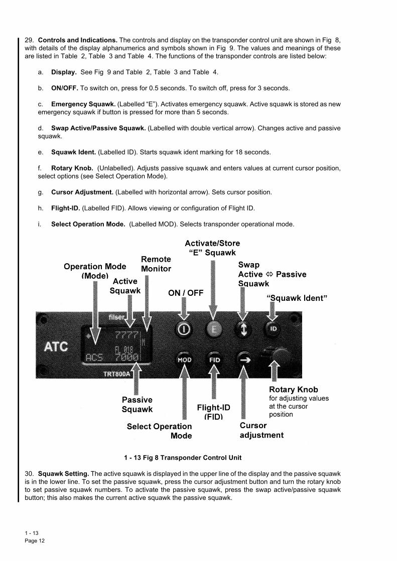
29. Controls and Indications. The controls and display on the transponder control unit are shown in Fig 8,witare
Transponder Control Unit
30is ito bu
1 - Pag
h details of the display alphanumerics and symbols shown in Fig 9. The values and meanings of these listed in Table 2, Table 3 and Table 4. The functions of the transponder controls are listed below:
a. Display. See Fig 9 and Table 2, Table 3 and Table 4.
b. ON/OFF. To switch on, press for 0.5 seconds. To switch off, press for 3 seconds.
c. Emergency Squawk. (Labelled “E”). Activates emergency squawk. Active squawk is stored as newemergency squawk if button is pressed for more than 5 seconds.
d. Swap Active/Passive Squawk. (Labelled with double vertical arrow). Changes active and passivesquawk.
e. Squawk Ident. (Labelled ID). Starts squawk ident marking for 18 seconds.
f. Rotary Knob. (Unlabelled). Adjusts passive squawk and enters values at current cursor position,select options (see Select Operation Mode).
g. Cursor Adjustment. (Labelled with horizontal arrow). Sets cursor position.
h. Flight-ID. (Labelled FID). Allows viewing or configuration of Flight ID.
i. Select Operation Mode. (Labelled MOD). Selects transponder operational mode.
1 - 13 Fig 8 Transponder Control Unit
. Squawk Setting. The active squawk is displayed in the upper line of the display and the passive squawkn the lower line. To set the passive squawk, press the cursor adjustment button and turn the rotary knobset passive squawk numbers. To activate the passive squawk, press the swap active/passive squawktton; this also makes the current active squawk the passive squawk.
13e 12

AP 101B-4901-15 1st EditionAvionics System
31. Emergency Squawk. To activate emergency squawk, press the emergency squawk button. The pre-stored emergency squawk (“E Squawk”) code activates and the previously used active squawk is stored asthe new passive squawk. The passive squawk can be adjusted by using the rotary knob and is activatedusing the swap active/passive squawk button. To store the current active squawk as the new emergencysquawk (replacing the factory setting of 7700 or the previously stored code) press and hold the emergencysquawk button for approximately 5 seconds until “S” is indicated.
Note: To prevent the inadvertent overriding of the emergency squawk setting, care should be taken toimmediately release the emergency squawk button after pressing it.
32. Configuring Flight-ID.
a. To view the programmed FID, the transponder is to be in standby mode.
(1) If not in STBY - press MOD repeatedly until STBY appears.
(2) Press FID button for less than 5 seconds.
b. To configure the Flight-ID, the transponder is to be in standby mode.
(1) Press MOD repeatedly until STBY appears.
(2) Press FID button for more than 5 seconds.
(3) When ‘CHANGE FID’ is displayed, release FID button.
(4) Enter the Flight-ID from the left, without spaces, using the cursor button and rotary knob.
(5) Press and release MOD to save and return to STBY.
Note: There are two transponders fitted, if use of the ‘out of use’ controller is anticipated, care is to be takento ensure the Flight ID is correctly configured to match the ‘in use’ controller.
33. Display Brightness. To alter the display brightness, in active mode (not standby) press the cursoradjustment button for 2 seconds and adjust the brightness with the rotary knob. To return to normal operation,press the cursor adjustment button or wait for 5 seconds.
34. Remote Monitor. The dual transponder system can be controlled from either cockpit. The remote
monitor indications are in the right hand margined part of the display and give the controllers’ status. Table3 identifies the remote monitor symbols. Transponder Display
1 - 13 Fig 9 Transponder Display
Remote monitor
1 - 13Page 13 (AL 1)

Table 2 - Transponder Display Error Messages
I
I
I
1 - Pag
Table 3 - Transponder Display Values and Meanings
Table 4 - Remote Status And Traffic Indications
ndication Meaning RemarksPLL Phased Locked Loop error Internal errorTRX Transmit failure Check antenna and wiringDC Low internal voltage Internal error
FPG Floating Point Gate Array failure Internal errorBAT Battery power low Battery, generator or internal fault
ndication Meaning Remarks7000 Active Squawk2000 Passive Squawk Can be swapped with active squawk by
pressing Swap Active/Passive Squawk buttonFL 030 Flight Level Flight Level (in 100 ft steps)FLerr Invalid altitude measuring Outside of minus 1000 to + 35,000 ft, C mode
is inactiveSTBY Transponder is ready to respond Transponder does not emit squitter or
interrogation repliesACS Standard condition: mode A, mode C and
mode S operationalTransponder responds to mode A, C and S interrogations
A-S Mode A and S only Altitude is not transmitted on either C or S requests. All other mode A and mode S data is transmitted
AC- Transponder replies only on mode A and mode C interrogations
Occurs if no 24 bit address has been entered into the transponder
A- Transponder replies only on mode A interrogations
Occurs if no 24 bit address has been entered into the transponder
IDT Transmits Ident-Marking (SPI indicator) ID (Squawk Ident) has been pressed - active for 18 seconds
R Transponder replies on mode S interrogations
. Transponder is locked to a ground station and will be directly addressed
Lock information (indicated as a single dot by the diamond)
ndication Meaning RemarksMA
X
MasterAuxiliary
Incorrect setting
Independent of selected operational mode auxiliary device does not emit downlink formats(X& is displayed if both transponders are running in the same M/A status
+ Remote message received Is displayed after reception for a short period of time
C
!
D
Remote device connected
Remote device connected but different configuration data detected
Remote interface is disabled
If remote device is not connected indication remains cleared(!) is displayed if connected transponders have inconsistencies in aircraft dependent configuration setup (e.g. ICAO address)Enable/disable remote data interface in device setup
13e 14

AP 101B-4901-15 1st EditionAvionics System
35. Limitation. The TRT800A is cleared to l6g. If this limit is exceeded the system should be monitored forerror messages and functionality confirmed by Air Traffic Services.
VHF Navigation Unit
36. General. A VOR/ILS/marker beacon installation (ARI 23434) comprises a control unit on the lowerinstrument panel in both cockpits, a combined VHF navigation and marker beacon receiver, and associatedaerials. 160 VOR channels and 40 ILS channels are provided, VOR frequencies in the range 108 to 117Q95MHz can be selected in 50 kHz steps. Localiser frequencies in the range 108Q1 to 111Q95 MHz can beselected in 50 kHz steps; glidepath frequencies are automatically paired with localiser frequencies.
37. Displays. The aircraft navigation situation is depicted on the HSI in each cockpit.
38. ILS. When the navigation mode selector is set to VOR ILS and an ILS frequency is selected on the VHFnavigation control unit, deviation from the localiser centre line and from the glidepath is shown on each HSI;localiser and marker audio signals are fed to the CCS. If the glidepath signal is weak or inaccurate the VERTwarning flag is displayed on each HSI; if the localiser signal is weak or inaccurate the NAV flag is displayedon each HSI. With ILS selected the VOR bearing pointers park horizontally.
39. VOR. When the navigation mode selector is set to VOR ILS and a VOR frequency is selected on theVHF navigation control unit, deviation from the VOR centreline and flying to/from are shown on each HSI.The VOR bearing is displayed on a bearing pointer and VOR audio signals are fed to the CCS. If the VORsignal is weak or inaccurate the VOR bearing pointers park horizontally, and the NAV flag is displayed on theselected HSI. The unselected HSI continually displays its NAV flag.
Note: With VOR selected the VERT flags of each HSI are displayed. VHF Navigation Control Unit
1 - 13 Fig 10 VHF Navigation Control Unit
40. Controls and Indicators. The controls and indicators comprise those on the VHF navigation control unit(Fig 10), the navigation mode selector and repeater in both cockpits, the HSI selector, and the marker lights.Selecting either control unit ON automatically switches the other control unit on; operating any switch oneither control unit automatically gives control of the receiver to that control unit. The preset and activefrequencies are displayed on the control unit in command, while the other control unit only displays the activefrequency. Table 5 shows the VHF navigation control unit controls.
1 - 13Page 15 (AL 1)

Table 5 - VHF Navigation Controls
41whmaVH
42pa
Tra
WASonothe
43of tan
2-mPaseDiDiST
3-Mof
AC
TELig
An
AnCo
Nabu
1 - Pag
. Marker. A blue light, inscribed MARKER, on the upper instrument panel of both cockpits, comes onen a marker signal is received; the period of operation of the light is a function of the signal strength at therker receiver. The filament of the light can be tested for serviceability by pressing the TEST button on theF navigation control unit. Power for the test is from the essential services busbar.
. Built-in Test. The serviceability of the system can be checked using the built-in test (see para 54 and
Controls/Marking Functionposition rotary power and ode switch selecting
OFF - Power offON - Navigation receiver on
ir of rotary manual frequency lector switches
Select required frequency
gital preset frequency display Displays preset frequencygital active frequency display Displays active frequencyO button Used in conjunction with XFR/MEM switch to store up to four preset
frequenciesposition switch, XFR/off/EM, spring-loaded to centre f
MEM (held down) - enters previously stored frequencies into the preset frequency display
XFR (held up) - transfers preset frequency display to active frequency display and vice versa
T button Displays active frequency only; lower display consists of dashes. When pressed for about two seconds the active frequency can then be altered by the manual frequency control knobs. A further press restores the controller to normal 2-display mode
ST button Activates built-in test (BIT) circuitht sensor Determines, automatically, the level of brightness of the displays. The top
display is always slightly brighter than the lowernunciator MEM display Illuminated whenever a 'stored' frequency is being displayed in the lower
displaynunciator RMT display Illuminated whenever the other control unit is in commandmparator annunciator ACT Momentarily illuminated when frequencies are being changed. If ACT
continues to flash, the actual tuned frequency is not identical to the frequency shown in the active display
vigation mode selector tton, VOR ILS/TACAN
Selects required navigation facility
ra 55).
ffic Alert and Collision Avoidance System (TCAS)
RNING: The TCAS installation does not detect or track aircraft which are not transponder equipped.me traffic may not be displayed due to traffic prioritizing or antenna shielding. Evasive manoeuvres shouldt be attempted based solely on traffic information on the display. Information on the display is provided to crew as an aid to visual acquisition and is not a replacement for ATC or see-and-avoid principles.
. General. The SkyWatch SKY 899 TCAS (ARI 50045/0) comprises a directional antenna mounted on tophe fuselage in front of the cockpit, a Transmitter Receiver Computer (TRC) located below the cockpit floor,d a Cockpit Display Unit (CDU) in each cockpit.
a. The antenna transmits omni-directional Mode C interrogations, and receives directional replies fromtransponder-equipped aircraft within 35 NM laterally and 10,000 ft vertically.
b. The TRC converts signals from the antenna into an on-screen picture of intruder locations and, ifnecessary, aural traffic advisories. The TRC can track up to 35 aircraft simultaneously but, to reduce
13e 16

AP 101B-4901-15 1st EditionAvionics System
clutter, only displays the 8 most threatening aircraft. The TRC also has inputs from the directional gyro,servo encoding altimeter, left weight-on-wheels microswitch, undercarriage selector valve and thetransponders. The TRC has built-in test equipment to detect faults and verify correct operation.
c. A CDU is located in each cockpit on the upper main instrument panel. Each CDU has a combinedon/off and brightness knob marked OFF/BRT and 4 pushbuttons. In each operating mode a labelindicating the pushbutton function is displayed on the screen next to each button. If no label is displayed,that button is inoperative in that mode. TCAS CDU Standby Mode Screen
1 - 13 Fig 11 TCAS CDU Standby Mode Screen
d. In the in-flight operate mode (OPR), the CDU displays the computed position of detected (intruder4aircraft relative to the host aircraft. The host aircraft is always depicted at the centre of the display. Asolid circle represents a Traffic Advisory (TA) indicating an intruder which may pose an immediatecollision threat. TAs may also be accompanied by an aural warning. An open diamond represents OtherTraffic (OT). A 2-digit data tag, showing the intruder4s relative height in hundreds of feet, is displayedabove (for higher traffic) or below (for lower traffic) the traffic symbol. Additionally, higher traffic has a
positive symbol and lower traffic a negative symbol. Non-altitude reporting intruders do not display a datatag and are considered to be co-height for the computation of TAs. A vertical trend arrow is displayed,in the correct sense, to the right of the traffic symbol when the intruder is climbing or descending atgreater than 500 fpm.
e. With the undercarriage retracted the TCAS operates in Sensitivity Level B (SLB). A TA is generatedwhen an intruder comes within 0.55 NM laterally or 800 ft vertically, or is on a course which will interceptthe host ac within 30 seconds. This time is reduced to 20 seconds for non-altitude reporting intruders. InSLB, any new TA is accompanied by an audio warning of (Traffic Traffic4.The audio warning sounds onceonly, but the TA symbol remains for as long as the intruder poses a threat, and for an additional 8seconds after it ceases to meet the criteria. The audio warning sounds in both cockpits even when onlyone CDU is selected ON. The warnings cannot be muted. When the undercarriage is selected down theTCAS operates in Sensitivity Level A (SLA). The criteria for TA generation are reduced to minimizenuisance warnings in the takeoff and landing phases and are 0.2 NM laterally or 600 ft vertically, or whenthe computed intercept is within 20 seconds (15 seconds for non-altitude reporting intruders). In SLAaudio warnings are inhibited. As an additional guard against nuisance warnings after takeoff, thetransition from SLA to SLB is delayed, via the left main gear weight-on-wheels microswitch, for 60seconds.
1 - 13Page 17 (AL 1)

TCAS CDU In-Flight Operate Mode Screen
1 - Pag
1 - 13 Fig 12 TCAS CDU In-Flight Operate Mode Screen
f. The volume of airspace displayed is selectable using the pushbuttons. Selectable ranges are 15, 6and 2 NM. An outer circle represents the selected range; an inner circle represents the next range down.An inner ring is not shown in 2 NM scale. Selectable vertical bands are Unrestricted (UNR), Above(ABV), Normal (NRM) and Below (BLW) (see Table 6). A label next to each button indicates thecurrently selected range or height band. The TCAS continues to track up to 35 ac regardless of therange displayed. OT outside the selected range and/or height is not displayed. However, TAs aregenerated for intruders outside the selected display zone. An out-of-range TA is shown as a semi-circleat the edge of the display at the correct bearing. An out-of-vertical band TA is shown as a correctlypositioned solid circle, however its height is shown at the maximum height selected until it comes withinthe selected height range.
Table 6 - Vertical Mode Height Bands
Vertical Mode Max look-up Max look-down
g. A message button allows system messages to be displayed. The MSG label is shown, next to thebutton, in contrast invert whenever a new message is available and unhighlighted when messages havebeen read. In standby mode the MSG label remains on the screen even when there are no messages.
h. When the TCAS is selected ON, it enters a power-on self test and the display shows themanufacturer4s logo. Following the test, if the ac is on the ground, the system enters standby mode andthe standby screen is displayed. In standby, the TCAS waits for five minutes for critical sensors to warmup before displaying a failed screen or failure messages. If the TCAS is selected to operate it only waitstwo seconds before displaying failure messages. In standby the TCAS does not interrogate, process ordisplay traffic. If the TCAS is selected ON in the air, and passes the power-on test, it enters operatemode, in NRM and 6NM scales.
ABV 9,000 ft 2,700 ftNRM 2,700 ft 2,700 ftBLW 2,700 ft 9,000 ftUNR 9,900 ft 9,900 ft
13e 18

AP 101B-4901-15 1st EditionAvionics System
i. In standby mode on the ground, pressing the button labelled OPR switches the TCAS into operatemode, in ABV and 6 NM scales, and the button label changes to STB. In the air, the button is not labelledand standby cannot be selected. The TCAS automatically switches from standby to operate 8-10seconds after takeoff, via the left weight-on-wheels microswitch, and switches back to standbyapproximately 24 seconds after landing. This delay prevents the TCAS entering standby during rollerlandings. The 60-second delay maintains the TCAS in SLA mode to minimize audio warnings duringcircuits.
Note: After 60 seconds the TCAS enters SLB mode; audio warnings may therefore sound when theundercarriage is up.
j. A button labelled TEST is available in STB or failed mode. Pressing the button initiates a self-testand the test screen is displayed. At the end of the test, an audio (Skywatch system test passed4 or similarfailure message is generated and the display reverts to the previous screen. If a test pass message isheard without the test screen being displayed select the system OFF.
k. The TCAS is powered by the main busbar. The maximum loading is 2 amps. Circuit protection isprovided by circuit breakers 90 and 91 in the rear cockpit.
l. To prevent damage, caused by transient power surges, ensure that the TCAS is selected OFF priorto and during engine start.
44. Normal Use.
a. After start, turn the OFF/BRT switch ON and to the desired brightness. If required, press the buttonlabelled TEST to initiate a self test.
b. After landing, select the TCAS OFF before switching off the transponder.
45. Use in Abnormal Conditions. When the TCAS detects a fault it determines whether the system hasfailed or is just degraded. A failed system cannot perform any collision warning functions. A degradedsystem can perform some collision warning functions, but may not be able to provide some features.
a. Response to a Failed System.
(1) In the case of a failed system the TCAS displays a (SKY899 FAILED4 screen. All errorsindicated by a fail screen prevent continued operation of the system. If the failure is caused by lossof transponder altitude encoding to the TCAS, the messages (Barometric Input Error4 and (Error 204
will be displayed on the fail screen. In this case, confirm that the transponder is not selected OFF.It may be possible to recover the system by momentarily selecting the transponder OFF and ON.
(2) In any other case, or if the Error 20 remains, and conditions permit, press the TEST button. Theresulting self-test may provide another error code to be noted. Press the message button and noteany degraded items listed. If the failure condition remains select the system OFF.
b. Response to a Degraded System. In the case of a degraded system, MSG will be highlighted onthe traffic screen. If conditions permit, press the message button and note the faults listed for anysubsequent engineering investigation. Press the EXIT button to revert to the previous screen.
c. If, at any stage, the TCAS provides erroneous information, or becomes a distraction, select thesystem OFF.
Underwater Locator Beacon
46. An underwater locator beacon, contained in a crash-resistant container, is in the rear fuselage attachedto the accident data recorder (ADR). The battery-operated beacon is self-contained and requires no aircraftelectrical power. On contact with water, a water-sensitive switch activates the battery. When the beacon isactivated, ultra sonic pulses are emitted which can be detected under water, at distances of 6000 to 12,000feet, depending on conditions, for approximately 30 days.
1 - 13Page 19 (AL 1)

NORMAL USE
Ge
47the
Gr
48sw
Be
49an
50
51
52
1 - Pag
neral
. Set the U/VHF volume at maximum to ensure correct receiver sensitivity; adjust the audio volume with station box RX volume control.
ound Intercom
. To achieve ground intercom ensure either an external DC power supply is connected or both batteryitches are ON, and select:
a. The EXT IN'COM switch ON.
b. The amplifier selector to NORM and adjust the front cockpit CCS I/C volume control as required.
fore Flight
. General. Before solo flight check that the rear cockpit standby UHF switch is OFF. Ensure that headsetd personal equipment connector are properly connected.
. CCS Station Box.
a. Set the amplifier selector to NORM.
b. Adjust the I/C volume control as required.
c. Set the function selector as required.
d. Switch on the required receiver audio switches.
e. Adjust the RX volume control as required.
. U/VHF Transceiver.
a. Select U/VHF SEL in a cockpit.
b. Select TR or TR+G.
c. Set the VOL control to maximum. Re-adjust station box RX volume control as required.
d. Set Manual. Press the TEST button. Check tone (UHF) or background noise (VHF) is present and
888.88 is on the frequency display.
e. Release the TEST button.
f. Set Manual or Preset and the frequency as required.
g. Repeat the test on the second U/VHF controller by first selecting U/VHF SEL in the other cockpit.
. Standby UHF Transceiver.
a. Set the function selector and audio selector switches on the CCS to U/STBY.
b. Set the standby UHF switch to ALT; check transmission and reception.
c. Adjust RX volume.
d. Set the function selector switch to V/UHF.
13e 20

AP 101B-4901-15 1st EditionAvionics System
e. Set the standby UHF switch to OFF.
53. Transponder.
a. Select TPDR/SEL in a cockpit.
b. Turn the transponder ON (turn on both if dual) and ensure in STBY mode. If not, press MODrepeatedly until STBY appears.
c. Set call-sign into the FID and press MOD to save.
d. Press E to confirm that emergency squawk 7700 is set.
e. Reset squawk as required.
f. Set mode as required.
54. VOR.
a. Switch the VHF navigation control unit ON and select the frequency of a VOR beacon which is outof range.
b. Select VOR ILS on the navigation mode selector.
c. Select the front cockpit HSI and set the track to 360L.
d. Press and hold the TEST button on the navigation control unit.
e. After approximately two seconds verify that the NAV flag disappears, the deviation bar centres andthe to-flag appears.
f. Verify that the VOR pointer shows 360L magnetic bearing.
g. The MARKER light flickers.
h. The navigation control unit should display the diagnostic code ̀ 00'. If any other number is displayedrecord it for later diagnosis.
i. Release the TEST button and verify that the NAV flag on the HSI comes into view and that the VORpointer parks horizontally.
j. Select the rear cockpit HSI and repeat the test procedure from the rear cockpit.
55. ILS/Marker Beacon.
a. Switch the VHF navigation control unit ON and select an ILS frequency.
b. Select VOR ILS on the navigation mode selector.
c. Select the MKR audio switch on the cockpit station box to on.
d. Press and hold the TEST button on the navigation control unit.
e. Verify that the NAV and VERT flags of the HSI are in view.
f. Verify that after approximately three seconds:
(1) The NAV and VERT flags go out of view.
(2) The track deviation bar deflects right approximately 2/3 full scale.
1 - 13Page 21 (AL 1)

(3) The glidepath pointer deflects down approximately 2/3 full scale.
56
Sy
57
1 - Pag
g. The MARKER lights should flicker and a 30 Hz tone should be heard in the headphone.
h. The navigation control unit should display the diagnostic code ̀ 00'. If any other number is displayedrecord it for later diagnosis.
i. Release the TEST button.
j. Verify that the NAV and VERT flags come into view, the MARKER light goes out and the 30 Hz audiotone ceases.
k. Select the rear cockpit HSI and repeat the test procedure from the rear cockpit.
. Tacan.
a. Select MODE on the tacan control unit function switch.
b. Select TACAN on the navigation mode selector.
c. Select the front cockpit HSI.
d. Set the HSI track pointer to 360L and check digital track read-out (top right) displays 0 m 1.
e. Select TST on the Tacan control unit TEST/TRANSFER switch. Release and check:
(1) The NAV flag goes out of view for approximately 3 seconds then appears.
(2) The digital distance read-out displays 0 m 0.5 miles.
(3) The bearing pointer indicates 180 m 2L.
(4) The 'from' flag is displayed.
(5) The track deviation bar is central.
f. Set the HSI track pointer to 180L; check the 'to' flag is displayed and the track deviation bar is central.
g. Move the front HSI track pointer through 090L and 270L to check the 'to/from' flags reverse.
h. Select the rear cockpit HSI and repeat the test procedure from the rear cockpit.
stems Operation
. U/VHF.
a. Set the CCS function selector to V/UHF and set the V/UHF receiver audio switch to on.
b. Select U/VHF SEL in the appropriate cockpit.
c. Select the U/VHF rotary function switch to TR or TR+G.
d. With the U/VHF transceiver mode switch at P, select the required channel; with the mode switch atM, set the required frequency manually. Adjust the volume control as required.
e. To transmit on the UHF guard channel (243 MHz) select Gu on the mode switch or select M and set243 MHz manually.
f. To transmit on the VHF guard channel (121Q5 MHz) select Gv on the mode switch or select M andset 121Q5 MHz manually.
13e 22

AP 101B-4901-15 1st EditionAvionics System
58. Transponder. Pre-flight, select ACS. The transponder will then respond to Mode A, C and Sinterrogations.
59. VOR/ILS/Marker Beacon.
a. Switch the navigation control unit ON. If the active frequency only is displayed press the ACT buttonfor about two seconds.
b. Select the frequency required and transfer to the active (upper) display by pressing the XFR/off/MEM switch to XFR.
c. Select VOR ILS on the navigation mode selector and adjust the track indicator as required.
d. To recall a stored frequency, push the XFR/off/MEM switch to MEM as necessary until theappropriate channel (CH1 to CH4) appears in the upper display; the associated preset frequency showson the lower display. Transfer to the active display (see para 59b).
e. Any or all of the four preset frequencies can be changed as follows:
(1) Push the XFR/off/MEM switch to MEM as necessary until the required channel appears in theupper display.
(2) Select the new frequency.
(3) Push the STO button twice (within five seconds).
(4) Repeat (1) and confirm the new frequency appears in the lower display.
Note: DME range is displayed on each HSI if the appropriate Tacan channel is selected and the Tacansystem is operating. Marker beacon reception is automatic.
60. Tacan.
a. On the Tacan control unit select MODE and rotate the function switch to select RX or T/R and selectthe required channel.
b. Select TACAN on the navigation mode selector.
Note: During a Tacan approach, propeller induced modulation of the Tacan signal may cause each HSIbearing pointer to oscillate m2L at 1Hz with simultaneous displacement of the track deviation bar.
USE IN ABNORMAL CONDITIONS
Electrical Failure
61. Compass. If the compass system fails (warning flags appear on each HSI) both HSIs are inoperative;neither TACAN derived information nor VOR/ILS information can be displayed.
62. Generator. If the generator goes off line (GEN caption illuminated) and cannot be reset, full electricalpower is available from No 1 battery (and No 2 battery if reconnected). Switch off unnecessary avionics andminimize radio transmissions.
Communications Malfunctions
Note: The absence of sidetone when transmitting is an indication that the power output has fallen below apreset level; the equipment may still be transmitting. Following generator failure a reducing battery voltagecauses a progressive loss of sidetone.
1 - 13Page 23 (AL 1)

63. Main U/VHF Transceivers.
64bo
65on
66cod
Air
67sel
1 - Pag
a. If the preset channel selector is suspect, use the manual tuning facility.
b. If receiver serviceability is suspect, press the TEST button; UHF serviceability is confirmed if the 1kHz tone signal is obtained. VHF serviceability is confirmed if background noise is obtained.
Note: The 1 kHz tone is transmitted on the selected frequency while the test button is pressed.
c. At any time that the serviceability of the main U/VHF is suspect, select the function selector andaudio selector switches on the CCS to U/STBY and ensure the U/STBY is switched to GRD.
. CCS Normal Microphone Amplifier. If the CCS normal microphone amplifier fails, set the CCS stationx amplifier selector to FAIL. When flying dual, advise the occupant of the other cockpit of the action taken.
. Transmit Button. If the throttle lever transmit button fails, use the alternative switch, marked ALT TX, the left console forward of the throttle.
. Transponder Failure. If the transponder serviceability is suspect, recycle the function switch and thee; if serviceability is still suspect, transfer control to the transponder in the other cockpit.
craft Emergency
. In the event of an aircraft emergency select transponder emergency code by pushing the emergencyect button which then illuminates. Ensure that the function selector is set to ON or ALT.
13e 24
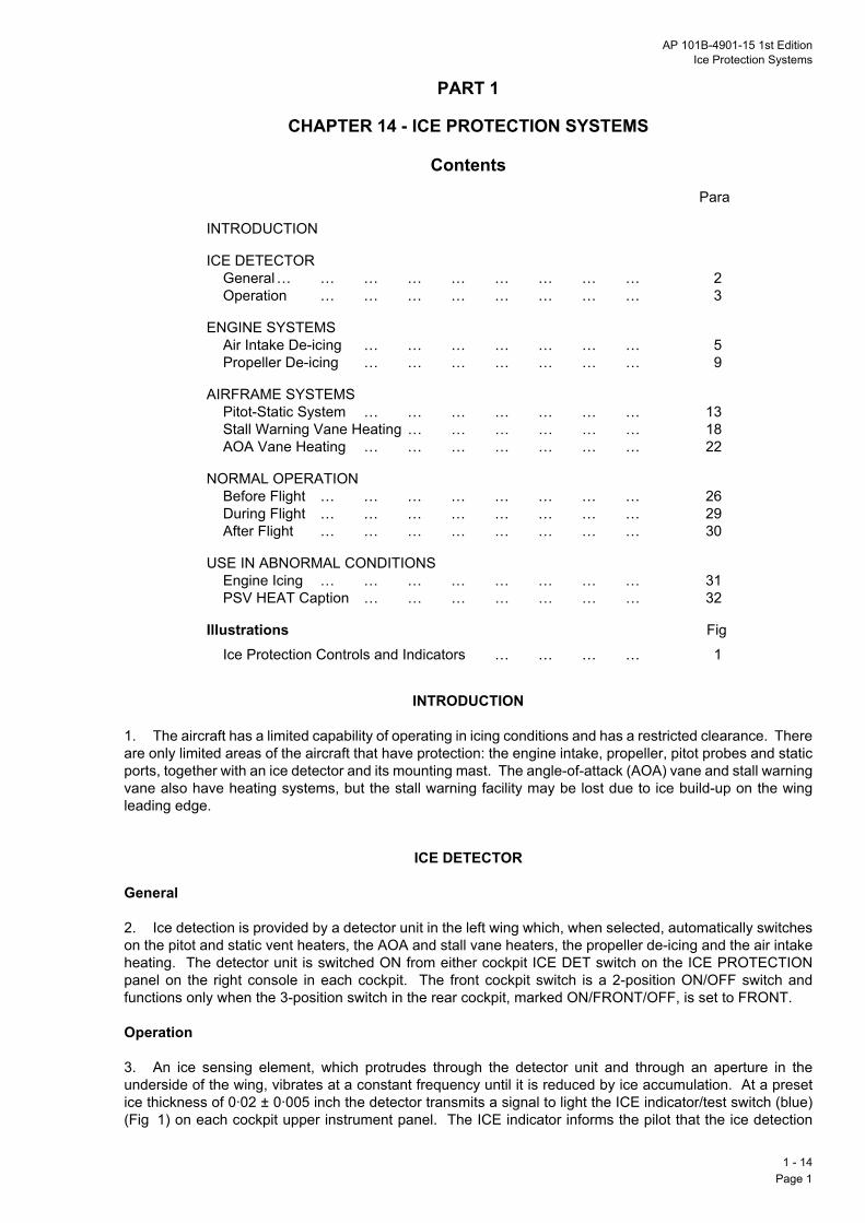
AP 101B-4901-15 1st EditionIce Protection Systems
PART 1
CHAPTER 14 - ICE PROTECTION SYSTEMS
ContentsPara
Illustrations Fig
INTRODUCTION
1. The aircraft has a limited capability of operating in icing conditions and has a restricted clearance. There
INTRODUCTION
ICE DETECTORGeneral… … … … … … … … … 2Operation … … … … … … … … 3
ENGINE SYSTEMSAir Intake De-icing … … … … … … … 5Propeller De-icing … … … … … … … 9
AIRFRAME SYSTEMSPitot-Static System … … … … … … … 13Stall Warning Vane Heating … … … … … … 18AOA Vane Heating … … … … … … … 22
NORMAL OPERATIONBefore Flight … … … … … … … … 26During Flight … … … … … … … … 29After Flight … … … … … … … … 30
USE IN ABNORMAL CONDITIONSEngine Icing … … … … … … … … 31PSV HEAT Caption … … … … … … … 32
Ice Protection Controls and Indicators … … … … 1
are only limited areas of the aircraft that have protection: the engine intake, propeller, pitot probes and staticports, together with an ice detector and its mounting mast. The angle-of-attack (AOA) vane and stall warningvane also have heating systems, but the stall warning facility may be lost due to ice build-up on the wingleading edge.
ICE DETECTOR
General
2. Ice detection is provided by a detector unit in the left wing which, when selected, automatically switcheson the pitot and static vent heaters, the AOA and stall vane heaters, the propeller de-icing and the air intakeheating. The detector unit is switched ON from either cockpit ICE DET switch on the ICE PROTECTIONpanel on the right console in each cockpit. The front cockpit switch is a 2-position ON/OFF switch andfunctions only when the 3-position switch in the rear cockpit, marked ON/FRONT/OFF, is set to FRONT.
Operation
3. An ice sensing element, which protrudes through the detector unit and through an aperture in theunderside of the wing, vibrates at a constant frequency until it is reduced by ice accumulation. At a presetice thickness of 0Q02 m 0Q005 inch the detector transmits a signal to light the ICE indicator/test switch (blue)(Fig 1) on each cockpit upper instrument panel. The ICE indicator informs the pilot that the ice detection
1 - 14Page 1

system has detected ice and has switched on the ice protection systems. Within seven seconds integralhefurswsecop
Noselwitdeproe.gsel
4.
Air
5.geintespr
6.
7.(blgiv
8.
Pro
9.opcon
10
1 - Pag
aters automatically de-ice the sensing element of the detector unit and, if the vibration frequency does notther reduce within 60 seconds, the detector unit signal cuts out, causing the ICE indicator to go out anditching off the ice detector automatic mode. If the vibration frequency does further reduce within 60onds a timer automatically resets the automatic mode, thereby ensuring that the ice detection system
erates continuously during moderate or severe icing conditions.
te: The ice detector is subject to random operation due to airframe vibration; when selected (on) it canect the ice protection systems on in any environment. Such spurious operations are usually associatedh selection of high engine power, or more than +3g, or landing. Nevertheless, the ice detector hasmonstrated a satisfactory capability of detecting icing conditions and of automatically selecting the icetection services on. However, an ICE warning indication should be confirmed by secondary indications,. ice forming on the canopy and wing leading edges. If, at any time, spurious operation is suspected,ect ICE DET OFF then ON to cancel unwanted ice protection system functions.
Power Supply. The ice detector is supplied from the main busbar.
ENGINE SYSTEMS
Intake De-icing
The top of the engine air intake duct is continuously de-iced by heat absorption from the propellerarbox oil. In icing conditions, the bottom of the duct is de-iced by engine P3 bleed air admitted to anrnal cavity via a solenoid-operated anti-ice valve. This valve also admits the bleed air to a tube whichays the hot air onto the inside of the skin of the intake lip. The valve is energized to open.
Anti-ice Valve Control.
a. Manual Control. The anti-ice valve can be selected ON (open) by an INTAKE switch on the ICEPROTECTION panel on the right console in each cockpit. The front cockpit switch is a 2-position ON/OFF switch and functions only when the 3-position switch in the rear cockpit, marked ON/FRONT/OFF,is set to FRONT.
b. Automatic Control. If the system is not selected ON manually, provided the ICE DET is selectedON, the control switches are electrically bypassed to open the anti-ice valve if the ice detector detectsice. Opening of the valve occurs simultaneously with the illumination of an ICE warning light/test switch(blue) on the right of each main instrument panel. The valve then remains open while the warningpersists.
Valve Position Indication. An indicator beside the control switch in each cockpit displays INTAKE ONue) when the valve is open, whether under manual or automatic control. There is also a slight rise in EGT
ing confirmation that the system is operating.
Power Supply. Power is from the load shedding busbar.
peller De-icing
The leading edge roots of the propeller blades are electrically de-iced by heater mats. Those onposite blades form two heater groups which are alternately heated, both under manual and automatictrol, for repeated 90-second periods.
. Control.
a. Manual Control. Manual selection of propeller de-icing is by a PROP switch on the ICEPROTECTION panel on the right console in each cockpit. The front cockpit switch is a 2-position ON/OFF switch and functions only when the 3-position switch in the rear cockpit, marked ON/FRONT/OFF,is set to FRONT. An ON selection activates the system, causing the timer to cycle power to both heatergroups in turn.
14e 2

AP 101B-4901-15 1st EditionIce Protection Systems
b. Automatic Control. If the system is not selected ON manually, provided the ICE DET is selectedON, the control switches are electrically bypassed if the ice detector detects ice. This activates thepropeller de-icing timer simultaneously with the initial illumination of the ICE warning light on the right ofeach main instrument panel. Cyclic heating of the two heater groups continues while the warningpersists.
11. Indication. A 3-segment electrical indicator, marked PROP/1/2 (blue), beside the control switch in eachcockpit is illuminated to confirm the correct sequencing of the heater mats. The upper segment PROPdisplays continuously when the system is on; the lower segments 1 and 2 display alternately during theheating phase of the associated heater group.
12. Power Supply. The heaters are powered by the load shedding busbar via a timer unit, brush block andpropeller slip-ring. Ice Protection Controls and Indicators
1 - 14 Fig 1 Ice Protection Controls and Indicators
1 - 14Page 3

AIRFRAME SYSTEMS
Pit
13au
14PRopOF
15PRconto
16PIT
17sta
Sta
18ge
19
20pathe
21
AO
22
23
24ICE
1 - Pag
ot-Static System
. The pitot tubes and static ports are de-iced by integral 28V DC heaters which are switched manually ortomatically.
. Manual Selection. Manual selection is controlled by the PITOT 1 and PITOT 2 switches on the ICEOTECTION panel on the right console of each cockpit. The front cockpit switches, marked ON/OFF, are
erative when the relevant rear switches are set to FRONT. The rear cockpit switches, marked ON/FRONT/F, have priority selection.
. Automatic Selection. The heaters are switched automatically when the ICE DET switch on the ICEOTECTION panel of either cockpit is switched to ON. The pitot-static heaters are then switched to suitditions encountered by the ice detector; in this mode the PITOT 1 and PITOT 2 switches can be selected
switch the heaters on manually for continuous operation.
. Heater Failures. Heater failure is indicated by an amber PSV HEAT caption on the CWP and an amberOT 1 or PITOT 2 caption, as applicable, showing on the ICE PROTECTION panel.
. Power Supplies. Power is supplied to the pitot-static 1 heaters from the main busbar and to the pitot-tic 2 heaters from the load shedding busbar.
ll Warning Vane Heating
. The stall warning lift detector is de-iced by integral vane, body and plate heaters wired through a landingar microswitch and thus is only operative when airborne.
. Control.
a. Manual Control. Manual control is by selecting ON the AOA/STALL switch on the ICEPROTECTION panel in either cockpit. The front cockpit has a 2-position ON/OFF switch and functionsonly when the 3-position switch in the rear cockpit, marked ON/FRONT/OFF, is set to FRONT.
b. Automatic Control. If the system is not selected ON, providing the ICE DET is selected ON, themanual control switches are electrically bypassed and the heaters switched (on) if the ice detectordetects ice.
. Heater Failure. Heater failure is indicated by an amber STALL caption on both ICE PROTECTIONnels and an amber PSV HEAT caption on each CWP. Power is supplied via a landing gear microswitch,refore, a failure is indicated if the heater is selected when on the ground.
. Power Supply. Power is from the load shedding busbar.
A Vane Heating
. The AOA sensor is de-iced by integral nose and vane heaters. A thermostat cut-out operates at 246LC.
. Control.
a. Manual Control. Manual control is by selecting ON the AOA/STALL switch on the ICEPROTECTION panel in either cockpit (see para 19a).
b. Automatic Control. If the system is not selected ON, providing the ICE DET is selected ON, themanual control switches are electrically bypassed and the heaters switched (on) if the ice detectordetects ice.
. Indication. A heater failure or thermostat cut-out is indicated by an amber AOA caption showing on both PROTECTION panels and a PSV HEAT caption is illuminated on each CWP.
14e 4
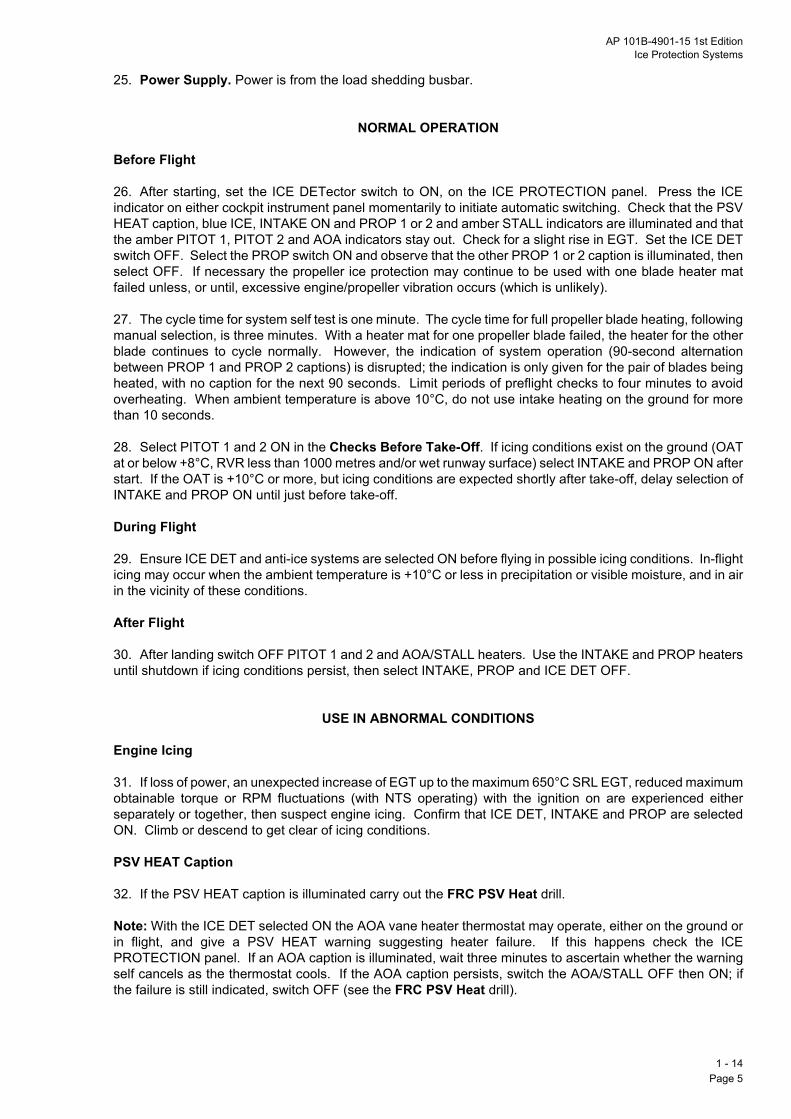
AP 101B-4901-15 1st EditionIce Protection Systems
25. Power Supply. Power is from the load shedding busbar.
NORMAL OPERATION
Before Flight
26. After starting, set the ICE DETector switch to ON, on the ICE PROTECTION panel. Press the ICEindicator on either cockpit instrument panel momentarily to initiate automatic switching. Check that the PSVHEAT caption, blue ICE, INTAKE ON and PROP 1 or 2 and amber STALL indicators are illuminated and thatthe amber PITOT 1, PITOT 2 and AOA indicators stay out. Check for a slight rise in EGT. Set the ICE DETswitch OFF. Select the PROP switch ON and observe that the other PROP 1 or 2 caption is illuminated, thenselect OFF. If necessary the propeller ice protection may continue to be used with one blade heater matfailed unless, or until, excessive engine/propeller vibration occurs (which is unlikely).
27. The cycle time for system self test is one minute. The cycle time for full propeller blade heating, followingmanual selection, is three minutes. With a heater mat for one propeller blade failed, the heater for the otherblade continues to cycle normally. However, the indication of system operation (90-second alternationbetween PROP 1 and PROP 2 captions) is disrupted; the indication is only given for the pair of blades beingheated, with no caption for the next 90 seconds. Limit periods of preflight checks to four minutes to avoidoverheating. When ambient temperature is above 10LC, do not use intake heating on the ground for morethan 10 seconds.
28. Select PITOT 1 and 2 ON in the Checks Before Take-Off. If icing conditions exist on the ground (OATat or below +8LC, RVR less than 1000 metres and/or wet runway surface) select INTAKE and PROP ON afterstart. If the OAT is +10LC or more, but icing conditions are expected shortly after take-off, delay selection ofINTAKE and PROP ON until just before take-off.
During Flight
29. Ensure ICE DET and anti-ice systems are selected ON before flying in possible icing conditions. In-flighticing may occur when the ambient temperature is +10LC or less in precipitation or visible moisture, and in airin the vicinity of these conditions.
After Flight
30. After landing switch OFF PITOT 1 and 2 and AOA/STALL heaters. Use the INTAKE and PROP heatersuntil shutdown if icing conditions persist, then select INTAKE, PROP and ICE DET OFF.
USE IN ABNORMAL CONDITIONS
Engine Icing
31. If loss of power, an unexpected increase of EGT up to the maximum 650LC SRL EGT, reduced maximumobtainable torque or RPM fluctuations (with NTS operating) with the ignition on are experienced eitherseparately or together, then suspect engine icing. Confirm that ICE DET, INTAKE and PROP are selectedON. Climb or descend to get clear of icing conditions.
PSV HEAT Caption
32. If the PSV HEAT caption is illuminated carry out the FRC PSV Heat drill.
Note: With the ICE DET selected ON the AOA vane heater thermostat may operate, either on the ground orin flight, and give a PSV HEAT warning suggesting heater failure. If this happens check the ICEPROTECTION panel. If an AOA caption is illuminated, wait three minutes to ascertain whether the warningself cancels as the thermostat cools. If the AOA caption persists, switch the AOA/STALL OFF then ON; ifthe failure is still indicated, switch OFF (see the FRC PSV Heat drill).
1 - 14Page 5

1 - Pag
Intentionally Blank
14e 6

AP 101B-4901-15 1st Edition
PART 2
LIMITATIONS
List of ChaptersChapter
AIRFRAME LIMITATIONS … … … … … … … 1
ENGINE LIMITATIONS … … … … … … … … 2
MISCELLANEOUS LIMITATIONS … … … … … … 3

Intentionally Blank

AP 101B-4901-15 1st EditionAirframe Limitations
PART 2
CHAPTER 1 - AIRFRAME LIMITATIONS
ContentsPara
General
1. The Tucano T Mk 1 is released in the flying training role by day and night (VMC and IMC) over land andwater, at ground level air temperatures in the range minus 10 to +30LC. It may be flown dual or solo. Forsolo flying the pilot is to occupy the front seat.
Centre of Gravity
2. The centre of gravity (CG) limits are:
a. Forward Limit:
General… … … … … … … … … 1Centre of Gravity … … … … … … … 2Mass … … … … … … … … … 4Airspeed … … … … … … … … 6Altitude … … … … … … … … … 7Manoeuvre … … … … … … … … 8Touchdown Sink Rate … … … … … … 12Tyre Limiting Speed … … … … … … … 13Taxy Distances … … … … … … … 14Rejected Take-Offs … … … … … … … 15
The limitations given in this Part are taken from the Release to Service (RTS), which is to be consulted to ascertain the latest release standard.Note: The limitations given are Normal Operating limitations which may be reached as often as required without undue risk.
(1) Up to 2300 kg. 3927mm aft of the Datum point.
(2) 2300 to 3000 kg. Limit moves linearly aft to 3963 mm aft of the Datum Point at 3000 kg.
b. Aft Limit: 4018 mm aft of the Datum point.
Note: The CG position is critical and to maintain CG within limits, either the crew composition may have tobe changed, the aircraft changed for one of a different basic moment or, in the other extreme, mass may haveto be carried in the baggage compartment.
3. The CG position is to be calculated before every flight taking into account the mass and moment of eachcrew member, the aircraft, fuel and baggage.
Mass
4. Take-off and Landing. The maximum mass for take-off or landing is 3000 kg.
5. Baggage Compartment. The maximum mass permitted in the baggage compartment is 20 kg. All itemsare to be tied down.
2 - 1Page 1 (AL 1)

Airspeed
6.
Alt
7.
Ma
8.
No+3
9.
10
2 - Pag
Maximum Airspeeds. The maximum airspeeds are:
a. Clean Aircraft:
(1) Flaps and Landing Gear UP: Sea level to 25,000 feet - 300 knots/0Q54 M.
(2) Flight in Severe Turbulence: 230 knots.
b. Operation of Airbrake and with Airbrake OUT: 300 knots/0Q54 M.
c. Flaps Selection and with Flaps Extended:
(1) MID: 175 knots.
(2) DOWN: 145 knots.
d. Landing Gear:
(1) Raising or lowering and with gear down: 145 knots.
(2) Lowering using emergency system: 120 knots.
itude
The aircraft is cleared for operation up to 25,000 feet.
noeuvre
The normal acceleration limits with landing gear and flaps UP and airbrake IN or OUT are:
a. Positive: +6 g or onset of stall warning/natural buffet whichever comes first.
b. Negative: minus 2Q5 g.
c. Design never exceed limits: +7/minus 3.3g.
te: With the camera equipment (SEM 057) installed in the rear cockpit, the aircraft is limited to betweeng and minus 0Q5g, because of the additional loading on the glareshield.
The normal acceleration limits with landing gear and/or flaps selected or extended are:
a. Maximum: 1Q7g while raising landing gear (above this value the retraction cycle is interrupted andresumes as g is relaxed); plus 2g (AUW up to 2900 kg) and plus 1.8g (AUW above 2900 kg) for all otherconditions.
b. Minimum: Zero g.
. Flight at Less than +0Q5g.
a. A single period of steady, inverted flight is limited to 30 seconds, after which 3 minutes are to elapsebefore further manoeuvres at less than +0Q5 g.
b. Manoeuvring below +0Q5g is limited to 20 seconds.
c. The duration at (or close to) zero g (including vertical flight up and vertical flight down) is limited to15 seconds. This is to ensure an adequate supply of oil to the propeller control, and fuel and oil to theengine.
1e 2
AP 101B-4901-15 1st EditionAirframe Limitations
d. Following excursions of more than 10 seconds below +0Q5g, a recovery period of twice the exposuretime is to be allowed before a subsequent excursion.
e. Only three successive excursions below +0Q5g are permitted, unless an additional 60-secondrecovery period is applied.
CAUTION: If the propeller governor oil accumulator becomes exhausted, propeller pitch control is lost untilnormal oil pressure is restored. Known colloquially as ̀ bogdown', the symptoms are a change in engine note,reducing RPM, reducing torque and rapidly increasing EGT. Unless rapid action is taken to throttle back andrestore the oil pressure, engine overtemperature damage may result.
11. Other Manoeuvre Limitations.
a. Flick Manoeuvres. Flick manoeuvres (i.e. the application of full pro-spin controls in excess of 95knots) are not permitted.
b. Rolling Manoeuvres. Rolling manoeuvres with up to full aileron applied are cleared through bankangles of up to 360L up to 280 knots; the normal acceleration at entry is to be between minus 1g and+4g. Above 280 knots gentle rolling manoeuvres only are permitted.
c. Stalling. Intentional stalling is permitted with the landing gear UP or DOWN and the flaps in the UP,MID or DOWN positions. In all cleared configurations the minimum height for stall entry is 4000 feetabove ground level (AGL).
d. Spinning. Intentional spinning is permitted, subject to the following warnings and limitations and theadvice in Part 3, Chapter 2:
WARNING 1: Failure to close the throttle to FLT IDLE in a developed spin may prolong or preventrecovery.
WARNING 2: Ailerons are to be kept as close to neutral as practicable throughout the spin and recovery.
WARNING 3: The rate of spin and the degree of oscillation during the spin exceed the limits laid downin Def Stan 00-970. These characteristics of the spin present a high risk of disorientation for the studentpilot and for this reason, when intentional spinning is planned, the aircraft should be captained by anexperienced Service pilot.
(1) The recommended maximum altitude for entry is 20,000 ft. The recommended minimum height
for entry is 10,000 ft AGL plus 1000 ft per intended turn e.g. a two-turn spin should be entered nolower than 12,000ft AGL.
(2) It is recommended that, where possible, the aircraft be trimmed for straight and level flight downto 100 knots (erect spinning) or 115 knots (inverted spinning) to minimize control forces in therecovery.
(3) Erect spinning with up to 30% torque selected is permitted for spins to the left only.
(4) The maximum speed for application of pro-spin controls is 95 knots.
(5) Flaps, landing gear and airbrake are all to be retracted.
(6) Recovery action is to be initiated after the following maximum number of turns:
(a) Erect spin - Six.
(b) Erect spin with power selected - Four.
(c) Inverted spin - Four.
2 - 1Page 3

(7) The minimum height for commencing recovery is 7000 feet AGL. If recovery (i.e., rotation
To
12
Ty
13
Ta
14
CAHesho
CAThab
Re
15a li
2 - Pag
ceased and speed increasing) has not been achieved by 3000 feet AGL the aircraft is to beabandoned.
(8) Deliberate inverted spinning is permitted.
e. Aerobatics. General aerobatics in the clean configuration, within the limitations of the Release toService, are permitted. However, the following are prohibited:.
(1) Aerobatics above 2900kg AUM.
(2) Flick manoeuvres.
uchdown Sink Rate
. The maximum permitted sink rate at touchdown is 690 feet per minute.
re Limiting Speed
. The maximum speed on the ground is 110 knots.
xy Distances
. Taxying distances pre- and post-flight should be limited as follows:
a. For the first movement of the day, in ambient temperatures up to +30LC, there are no limitations ontaxying distance.
b. When the turnaround time between flights is longer than one hour, the tyres may again be regardedas cool with an unlimited taxying distance.
c. When taxying prior to a second take off for a second or subsequent flight of the day within one hourof previous taxying movement, the taxy distance should be limited to 6 km.
d. For each 10LC decrease in ground level OAT below +30LC the one-hour turn around time inpara 14c above may be reduced by 20 minutes.
UTION 1: The tyres do not have fusible plugs and taxying greater distances may overheat the tyres.avy brake usage (e.g. after a rejected take-off) results in even higher temperatures, therefore, groundcrewuld not be allowed to approach the aircraft for at least 30 minutes after such braking.
UTION 2: The wheel brakes are not fitted with an anti-skid system. Heavy foot forces should be avoided.
e brake friction pads should be changed following an aborted take-off where the brakes were appliedove 70 knots.
jected Take-Offs
. Take-offs may be safely rejected at any stage and at any mass up to MTOM (3000kg), although there iskelihood of tyre burst should heavy braking be applied.
1e 4

AP 101B-4901-15 1st EditionEngine Limitations
PART 2
CHAPTER 2 - ENGINE LIMITATIONS
ContentsPara
Engine Operating Limitations
1. The Garrett TPE-331-12B engine with engine electronic control (EEC) operative is cleared for operationsubject to the limitations given in Table 2.
2. Manual Engine Control. With the EEC inoperative the maximum EGT is to be restricted to 560LC.Other limitations are as in Table 2.
3. Propeller Limitations. Propeller limitations are:
a. Minimum idle: 71% RPM.
b. Overspeed governor check: 105Q5% RPM.
c. Windmilling: See Table 1.
Table 1 - Propeller Windmilling Limitations
Engine Operating Limitations … … … … … 1Approved Fuels … … … … … … … 4Approved Lubricant … … … … … … … 5Ground Starting and Ground Running … … … … 6Engine Handling … … … … … … … 11Relighting … … … … … … … … 13
Propeller Speed (%RPM)
Max Time (Minutes)
100 to 28 1
Note: It is critical that the RPM does not stagnate within the band 18-28% as this is where resonance of themain shaft can occur with the consequential possibility of significant damage.
28 to 18 One transient 18 to 10 510 to 5 305 to 0 Unlimited
2 - 2Page 1

Table 2 - Garrett TPE-331-12B Operating Limitations
No
Nodo
No
Notra
Noat pefligpeprasaf
Nobe
No
Gr(EGr(E
Ai
Gr(EGr(EGr(ARe(ERe(ETaunTrco
2 - Pag
te 1: The start is to be aborted for any excursion above 770LC. Subsequently, observe the following:
a. If an excursion is less than one second and does not exceed 776LC another start may be attempted.
b. If an excursion is more than one second but less than three seconds and does not exceed 776LCanother start may be attempted, but a power check is to be made before flight.
c. If 776LC is exceeded the aircraft is to be placed unserviceable.
te 2: During the starting sequence it is important that the EGT limits are not exceeded and that the enginees not stagnate, particularly between 18 and 28%.
te 3: Following cold soaks engine oil pressure may be slow to rise and may then briefly exceed 8Q3 bar.
Operating ConditionsEGT (LC)
Torque (%)
Propeller Speed (%) Oil Temp (LC)
Oil Pressure (Bar)
ound Startingngine speed 70%)
770(1) - 80
(2)Minus 40
(Minimum)0 to 8.3
(3)ound Startingngine speed 100%)
770(1) - 104 to 106
(5sec)(4)(6)Minus 40
(Minimum) 0 to 8.3
rborne Relighting 770 - 104 to 106(5sec)
Minus 40(Minimum) 0 to 8.3
ound Operationsngine speed 70%) 560 100 72 to 73 110
(5) 2.8 to 8.3
ound Operationsngine speed 100%) 650 100 101
(6)110(5)
4.8 to 8.3(7)
ound Operationsir Cond at BOOST)(8) 650 100 82m1 110
(5) 2.8 to 8.3
versengine speed 70%) 560 81.8 - 110 4.8 to 8.3
versengine speed 100%) 650 81.8 - 110 4.8 to 8.3
ke-off and all flight conditionsless otherwise stated 650 100 101 55 to 110
(5)4.8 to 8.3(8, 9 & 11)
ansient (Take-off and all flightnditions)
660(5sec) (10) 101 to 104
(30sec)(6)127(5)
2.8 to 8.3(8)
te 4: Start locks are to be engaged for ground starting. 106% RPM is not to be exceeded. Five secondsnsient between 104 and 106% RPM is permissible.
te 5: Following cold soaks the start up oil temperature may not increase to 55LC until the engine has runidle for up to five minutes. Ground operation with engine oil temperature above 110LC and up to 127LC isrmitted provided the torque is less than 70%. A transient overtemperature to 127LC for take-off or duringht operations is permitted for up to five minutes provided the torque is reduced to less than 70%. Forriods in excess of five minutes reduce the torque further to lower the oil temperature and land as soon ascticable. For overtemperatures between 127 and 150LC reduce the torque to the minimum possible fore flight and land as soon as possible.
CAUTION: Operation with oil temperatures above 150LC may result in oil pressure loss and theresultant loss of propeller control.
te 6: Propeller speeds between 101 and 104% RPM are permitted for up to 30 seconds only. 104% may exceeded for five seconds to carry out overspeed governor checks.
te 7: At idle the minimum oil pressure is 2Q8 bar.
2e 2

AP 101B-4901-15 1st EditionEngine Limitations
Note 8: If oil pressure falls outside (above or below) permitted pressure limits, reduce power to the minimumrequired for safe flight and land as soon as possible.
Note 9: During flight at less than +0Q5g oil pressure indications decrease towards zero. For repetitivenegative g and inverted flight manoeuvres in excess of 10 but less than 20 seconds there is to be an intervalof normal oil pressure of at least twice the period of operation with subnormal oil pressure. The maximumtime for a single period of inverted flight is 30 seconds, after which three minutes are to elapse before furthermanoeuvres at less than +0Q5g.
Note 10: Selections to maximum power may cause a torque overshoot beyond 100% which is quicklyrecovered. Any torque overshoot that does not rapidly return to the 100% indication, or any transient torqueovershoot greater than 115%, should be dealt with by reducing engine torque and the aircraft returned tobase as soon as practicable. Torque overshoots greater than 106Q5% lasting for longer than five seconds andtorque overshoots of between 104Q9% and 106Q5% lasting for longer than 20 seconds should be dealt withby reducing engine torque and reporting the occurrence on return to base.
Note 11: At altitudes below or equal to 23,000 feet the minimum oil pressure is 4Q8 bar. At altitudes above23,000 feet the minimum oil pressure is 3Q4 bar.
Approved Fuels
4. The approved fuels are given in Table 3 and Table 4.
Table 3 - Standard Fuels
Table 4 - Alternative Fuel
NATO Code UK Joint Service DesignationStandard Fuels. The following fuels are approved for normal use:
F-34 Avtur/FSII F-40 Avtag/FSII
NATO Code UK Joint Service DesignationAlternative Fuel. The following may be used as an alternative fuel:
F-35 Avtur
Approved Lubricant
5. The following engine oil is cleared for use: OX 27.
Ground Starting and Ground Running
6. Surface Wind. The maximum permitted surface wind conditions for engine start given in Table 5:
Table 5 - Engine Start Surface Wind Limits
Note: If AL48 (FSII and lubricity additive) is added to F-35 in accordance with DEFSTAN 68-150, then F-35 may be used without restriction. Without AL 48 in the correct proportion, F-35 may only be used at fuel temperature above 0LC.
a. Crosswind component 40 knots. Limit exposure to crosswinds from the left and monitor the oil temperature
b. Headwind component 40 knotsc. Tailwind component 15 knots
2 - 2Page 3

7. Electrical Power for Starting. The engine may be started using an engine-driven external groundpoanarethrtem
CAnoact
8.secfolltheatt
9.minshu
CAanthe
10sub
En
11
12
Re
13les
2 - Pag
wer unit, the trolley battery electrical starter 4FE/5878721, or the internal aircraft batteries. Starting fromy other external accumulator power source is not cleared. Following cold soaks at or below 0LC all starts to be carried out using an approved ground power unit. Use of the internal batteries is to be limited to
ee start or dry crank cycles. Starts using internal aircraft batteries may be carried out in outside airperatures between 0LC and minus 10LC provided that either:
a. The aircraft has not been exposed in the environment for more than two hours since leaving aheated hangar; or
b. The aircraft has landed from the previous flight not more than two hours earlier.
UTION: When starting the engine using internal batteries the starting cycle may be prolonged. Starts mayt be achieved within 60 seconds and may result in rapidly increasing EGT which requires rapid shutdownion. Any start where the RPM stagnate should be aborted.
Start Attempts. Any start is to be aborted if self-sustaining RPM have not been achieved within 60onds. The starter/generator may be used for two failed starts or dry crank cycles each of 60 secondsowed by a successful start. A cooling interval of two minutes is to be observed between start attempts. If third start attempt is unsuccessful a further cooling period of 15 minutes is to be observed beforeempting further starts using the above sequence.
Restarting After Shutdown. Follow engine shutdown after a period of sustained running, observe a 10-ute cooling period before attempting to restart the engine. After any 10 to 30-minute period followingtdown, the propeller is to be turned by hand through 90L immediately before starting.
UTION: In the event of a failed start, fuel is dumped overboard via the engine bay combined drain systemd could fall on a hot exhaust duct giving a potential fire hazard. In addition to the cooling period, during restart, station a fire-watch adjacent to the right exhaust.
. Reverse Pitch. Periods of ground running with REVerse pitch selected are be limited to five minutesject to the oil temperature limitations. Between such periods observe a 30-minute interval.
gine Handling
. With EEC to NORMAL there are no restrictions.
. Selection of MANual and reversion to NORMAL is permitted as required subject to:
a. Engine torque is to be at 30% or below when selecting EEC NORMAL to MANual and 20% or belowwhen selecting EEC MANual to NORMAL.
b. The use of REVerse thrust is prohibited during landing with MANual selected.
c. After each reversion from MANual to NORMAL the pilot is to verify that the EGT is at or below650LC.
lighting
. Relights should be attempted in the range 115 to 200 knots below 20,000 feet. If the oil temperature iss than +4LC the chance of a successful relight is lowered.
2e 4

AP 101B-4901-15 1st EditionMiscellaneous Limitations
PART 2
CHAPTER 3 - MISCELLANEOUS LIMITATIONS
ContentsPara
Runway Surface
1. The aircraft may be operated from paved surface runways only.
Surface Wind
2. The following are the maximum permitted surface wind conditions for:
a. Canopy Opening. The maximum windspeed for opening the canopy is 40 knots. To avoid possibleinjury and/or damage to the structure external assistance is required when windspeed components
Runway Surface … … … … … … … 1Surface Wind … … … … … … … … 2Crew Changes… … … … … … … … 3Aircraft Arresting Gear Trampling … … … … … 4Aircraft Arresting Barriers … … … … … … 6Icing Conditions … … … … … … … 7Humidity/Rain … … … … … … … … 9Snow … … … … … … … … … 10Instrument and Night Flying … … … … … … 11Aircraft Approach Criteria … … … … … … 12Avionic Installations … … … … … … … 13Electrical System … … … … … … … 14Air Conditioning System … … … … … … 16Fuel System … … … … … … … … 17Ice Protection System … … … … … … 19Emergency Escape … … … … … … … 20Electromagnetic Compatibility … … … … … 23
exceed the following:
(1) Headwind - 25 knots.
(2) Tailwind - 25 knots.
(3) Crosswind from the left - 20 knots.
(4) Crosswind from the right - 15 knots.
WARNING: The canopy may blow closed, even in light winds, and cause damage to the structure and/or injury to occupants. Insert the canopy locking pin to prevent this.
b. Engine Start. See Chapter 2.
c. Taxying.
(1) Windspeed - 40 knots.
(2) Exposure to crosswind (particularly from the left when the oil cooler on the right intake isshielded by the aircraft nose) or tailwind components is to be kept to a minimum to keep the oil
2 - 3Page 1

temperature below 110LC. Additionally, crosswinds deflect engine exhaust over the downwind main
Cr
3.forensucfuman
Air
4.run
5.beoffret
WAor en
Air
6.
Ici
7.iceCleOff
WAwhcon
2 - Pag
wheel increasing tyre temperature.
d. Take-off or Landing.
(1) Crosswind component - 30 knots.
(2) Headwind component - 40 knots.
(3) Tailwind component - 10 knots.
ew Changes
Crew changes, whilst the engine is running, are permitted. The engine must be running in reverse thrust, the period that the canopy is opened, to limit carbon monoxide build up in the cockpit from engine exhausttry. Since running in reverse thrust removes the flow of air through the engine oil cooler, the time limit forh running is five minutes within the overriding oil temperature limitations. Due to the possible presence ofes, the incoming crew are to adopt the same procedure in the use of the environment conditioning system
d the selection of 100% oxygen that they would have made for a normal engine start.
craft Arresting Gear Trampling
The aircraft may cross tensioned arresting gear cables which are unsupported and in contact with theway.
Taxying across rigged and supported arresting cables, with support discs at 6-foot nominal spacing, may carried out at a slow walking pace, provided the landing gear doors are closed, the mainwheel brakes are and the nose of the aircraft is aimed at midway between adjacent support disc. The aircraft may cross aracted BAK-14 arrester cable support system without restriction.
RNING: Taxying over a supported arresting cable is prohibited, with either a deflated nosewheel tyre and/following lowering of the landing gear using the standby system, because of the risk of unintentionalgagement of the cable by aircraft structure.
craft Arresting Barriers
The aircraft is not cleared to use aircraft arresting barriers.
ng Conditions
The aircraft has a limited capability in icing conditions. The aircraft's surfaces are to be monitored for accretion, and if icing is suspected the aircraft is to be flown out of such conditions as soon as possible.
arance to operate in icing conditions defined as `light', `light/moderate' or `moderate' (Meteorologicalice definitions) is subject to the exposure limits set out in Table 1 and the following conditions:
a. Where icing exists at ground level the aircraft may be operated for the periods annotated`acceptable'; this covers total exposure during climb plus descent and approach in icing conditions, butnot any time spent in non-icing conditions above the icing layer.
b. Where the icing level occurs at some altitude above ground level, such that it is possible to fly belowthe icing layer to assist the clearance of ice from the canopy prior to landing, the total exposure timesmay be extended to those annotated `marginal'.
c. Flight in icing conditions is not to be continued into the region annotated `unacceptable'.
RNING: Exposure to icing conditions for periods longer than `marginal' may result in ice covering theole of the canopy. Furthermore, if the outside air temperature (OAT) is below 0LC, even out of icingditions, ice may not clear adequately for the pilot to be able to see external references for landing.
3e 2

AP 101B-4901-15 1st EditionMiscellaneous Limitations
8. Flight in icing conditions with the landing gear down should be kept to the minimum necessary for a safetake-off plus normal approach and landing.
Table 1 - Limitations for Flight in Icing
Humidity/Rain
9. The aircraft may be operated with dew-points up to + 20LC. Provided the aircraft is fitted with allprotective blanks/covers and the control column lock is engaged, the aircraft can be parked in heavy/drivingrain. If exposure to heavy rain is expected to exceed 1 hour the canopy cover is also to be fitted.
Snow
10. The aircraft is not cleared for operation in snow or from surfaces covered with snow/slush. Unavoidableoperations in snow/slush should be treated with caution. Accumulations of slush/ice in the recess below theoperating cam for the nose undercarriage weight-on-ground switch may result in malfunction of the switch,with an inability to move the throttle aft of FLIGHT IDLE after touchdown.
Instrument and Night Flying
11. The aircraft is cleared for instrument flight in IMC and at night.
Aircraft Approach Criteria
12. Approach Category. The aircraft Approach Category is B.
Met Office IcingSeverity Grading
Exposure Time(Minutes)
ResultingForward Visibility
Light 0 to 66 to 14
above 14
AcceptableMarginal
Unacceptable
Light/Moderate0 to 44 to 7
above 7
AcceptableMarginal
Unacceptable
Moderate0 to 22 to 5
above 5
AcceptableMarginal
Unacceptable
Avionic Installations
13. The following avionic installations may be used subject to the Notes below:
a. Communications control system (Note 1).
b. V/UHF/STBY UHF systems (Notes 2, 3 and 4).
c. ILS/VOR (Notes 5 and 6).
d. Tacan (Note 7).
e. SSR transponders (Note 8).
f. Main and standby compass systems.
g. TCAS (Note 9).
Note 1: In conjunction with the Mk 4A and Mk 4D flying helmets.
2 - 3Page 3
Note 2: Operation of the V/UHF radios may induce disturbances to the engine instruments. Thesedis
Noran
Nobewit
Noap
No
No
No
Notrabecre
Ele
14
15as
Air
16
WAat cocthiscarcon
2 - Pag
turbances are not to the engine system itself.
te 3: Above FL 160 at frequencies in the upper quarter of the UHF band, the maximum communicationge is decreased in the head-on aspect.
te 4: Communications quality may be degraded at frequencies in the upper quarter of the UHF bandtween aircraft aspects of 270L and 340L with the aircraft banked to the left, and between 020L and 090Lh the aircraft banked to the right.
te 5: VHF transmissions may deflect the localiser and VOR track deviation bar and cause the NAV flag topear.
te 6: UHF transmissions may cause the VERT flag to appear.
te 7: UHF transmissions may cause interference and cause the NAV flag to appear.
te 8: At intermediate ranges from an interrogator some loss of replies may occur.
te 9: The TCAS installation does not detect or track aircraft which are not transponder equipped. Someffic may not be displayed due to traffic prioritizing or antenna shielding. Evasive manoeuvres should not attempted based solely on traffic information on the display. Information on the display is provided to thew as an aid to visual acquisition and is not a replacement for ATC or see and avoid principles.
ctrical System
. Before take-off the generator current is to be less than 100 amps with the landing lamps OFF.
. If the generator fails, the electrical load is to be reduced to a minimum and the aircraft landed as soonpossible. Battery operation of the essential loads cannot be guaranteed for more than 30 minutes.
Conditioning System
. The air conditioning system is cleared for use subject to the following:
a. AUTO should be selected before selecting ON.
b. The system is to be selected ON immediately following engine start.
c. The crew should be on 100% oxygen until after the air conditioning has been selected to BOOSTafter start. For ground operation with the air conditioning off, 100% oxygen should be used.
d. Ground running at OAT above 20LC should be limited to 20 minutes pre- and post-flight.
e. BOOST is recommended for all flight conditions.
f. MANual should only be selected if the temperature control system fails in AUTO. If shutdown of theair conditioning system is considered an unacceptable first course of action and operation on MANualbecomes necessary, follow the procedures given in Part 1, Chapter 8.
g. RAM air may be used if the air conditioning system fails, but only when absolutely necessary.
RNING: On some aircraft the air conditioning system efficiency may be degraded significantly by leakageducting joints. Under these circumstances, pilot heat stress could be experienced, particularly in highkpit workload conditions at high speed, low level in ambient temperatures between +25LC and +30LC. For reason, pending improvements to duct sealing design and air distribution in the cockpit, take particulare to avoid and/or recognize symptoms of heat stress during flights exceeding 15 minutes in theseditions.
3e 4

AP 101B-4901-15 1st EditionMiscellaneous Limitations
CAUTION: The MANual selection supplies very hot air to the cockpit and temperature control is difficult.Repeated overheat shutdown of the system is very likely; this is accompanied by an AIR COND warning.Prolonged operation with MANual HOT selected could lead to failure of the front SSR transponder.
Fuel System
17. The fuel system tends to feed from one side or the other rather than together. Check before flight thatall four booster pumps function normally and monitor the fuel gauges to ensure asymmetry does not exceed100 kg.
18. Suction Defuelling Point. The suction defuelling point is not to be used for pressure refuelling. Nor isthe point to be used for routine defuelling; its use is to be restricted to emergency defuelling if the landinggear has collapsed.
Ice Protection System
19. Limit periods of preflight checks of the ice protection system to four minutes to prevent overheating.When the ambient temperature is above 10LC the intake icing should not be used for more than 10 seconds.
Emergency Escape
20. Ground Emergency Egress. The canopy fracturing system using either internal or external handles iscleared only for ground emergency egress. It is not designed, or cleared, for airborne use.
WARNING 1: There is a significant risk of damage to the front occupant's aircrew equipment assembly (AEA)during ejection from fragments of the front canopy; there is also a risk of minor laceration injuries to the limbs.In particular, the integrity of immersion coveralls (inner or outer) cannot be assured. The extent of injuries isminimised by reducing ejection speed and by wearing maximum thickness AEA.
WARNING 2: The ejection seats were designed and cleared for the boarding weight range of 68.4 kg to 108.2kg (nude weight plus AEA) and the 3rd to 99th percentile nude size range. Use by aircrew or passengerswhose anthropometric weight and size ranges are outside these limits increases the possibility of ejection-related injuries.
WARNING 3: Night vision goggles are not to be used.
WARNING 4: Operators should be aware that, due to physiological differences, female aircrew may be moresusceptible to ejection injuries when compared to their equivalent-weight male counterparts.
21. Ejection. The escape system using the Martin Baker 8LC1 and 8LC2 ejection seats is cleared for usethroughout the flight envelope; at ground level the minimum airspeed for successful operation is 70 knots.
Note 1: The approved scale of AEA is contained in AP 108B-0001-1 Schedule No 9.
Note 2: The preferred speed for premeditated ejection is 115 knots.
Note 3: High sink rates, high roll rates and/or adverse roll attitudes have significant effects on the terrainclearance required for a successful escape.
22. Command Ejection. The command ejection facility is cleared for use.
Note 1: The command ejection system ejects the rear crew member first. To ensure adequate separation,particularly at low IAS, there is a 1Q4 second delay before the front crew member is ejected. Aircrew shouldbe aware of the need for such a delay, if the command ejection system has been selected OFF.
Note 2: Following command ejection and in the event of seat separation failure, the front seat pilot must firstpull his seat firing handle before operating the manual separation handle.
2 - 3Page 5

Electromagnetic Compatibility
23
Nodis
Fy
2 - Pag
. The aircraft is cleared for use in the external electromagnetic environment given in Table 2.
te: At the field strength levels given for HIRTA Codes B and C, significant radio frequency-inducedturbances may occur to the engine instruments; these are not disturbances to the engine system itself.
Table 2 - EMC Field Strength Limits
Frequency Band Frequency Band Code
(OLD4 (Previous) Low Flying Grade
Susceptibility Grade
Power Density / Field Strength Limit
0.525 - 2.0 MHz A 2 VERY LOWUp to and including 26W/m2 (100V/m)
2.0 - 32.0 MHz B 3 LOWUp to and including 6W/m2 (50V/m)
32.0 - 790.0 MHz C 3 MEDUp to and including 1 W/m2 (20V/m)
0.79 - 4.5 GHz D 2 LOWUp to and including 100 W/m2 (200V/m)
4.5 - 40 GHz E 2 LOWUp to and including 100 W/m2 (200V/m)
lingdales HIRTA:
32.0 to 790.0 MHz C 2 LOWUp to and including 10 W/m2 (60V/m)
3e 6

AP 101B-4901-15 1st Edition
PART 3
HANDLING
List of ChaptersChapter
STARTING, TAXYING AND TAKE-OFF … … … … … 1
HANDLING IN FLIGHT … … … … … … … … 2
APPROACH AND LANDING PROCEDURES … … … … … 3
FLIGHT IN ADVERSE WEATHER … … … … … … 4

Intentionally Blank

AP 101B-4901-15 1st EditionStarting, Taxying and Take-Off
PART 3
CHAPTER 1 - STARTING, TAXYING AND TAKE-OFF
ContentsPara
General
1. The checks referred to in this chapter are listed in the Flight Reference Cards (FRC).
WARNING: The ejection seats and the MDC systems are a potential source of danger since their inadvertentoperation can cause fatal injuries. Therefore, safety precautions are to be observed at all times, i.e. theaircraft is to be left either Safe for Parking or Safe for Maintenance, as applicable, as defined below:
a. Safe for Parking. Safety pins fitted to the ejection seat firing handle and the canopy fracture firinghandle in each cockpit.
b. Safe for Maintenance. In addition to the safety pins fitted under sub para a, safety pins are also tobe fitted to the manual override sears.
CG Calculation
2. The CG position in the Tucano is critical. It is easily possible to exceed the aft CG limit if the heaviercrewmember occupies the rear cockpit and/or baggage is carried in the baggage compartment. Before everyflight, determine the CG position to ensure that it remains within the allowable limit of 4018 mm aft of datum.
General… … … … … … … … … 1CG Calculation … … … … … … … 2Preparation for Flight … … … … … … … 4Starting the Engine … … … … … … … 6Failure to Start… … … … … … … … 10Checks after Starting … … … … … … … 11Taxying … … … … … … … … … 12Take-Off Procedures … … … … … … … 14Loss of Power after Take-Off … … … … … 19
The CG is closest to the aft limit at high and very low fuel states, therefore, the calculation should be carriedout for maximum and minimum fuel states expected during the sortie.
3. To calculate the CG, determine the total moment using the aircraft moment (from Section 1 of the F700),the crew moments (Table 1), the fuel moment (Table 2) and the baggage moment (Table 3). Divide thetotal moment by the aircraft total mass to establish the CG position in metres aft of the datum point. Forexample:
Aircraft mass and moment: 2152.7 kg & 8499.23 mmCrew: front 78 kg, rear 82 kgFuel: 540 kgBaggage: 12 kg Total Mass: 2152.7 + 78 + 82 + 540 + 12 = 2864.7 kgMoment: 8499.23 + 262.9 + 391.1 + 2151.4 + 74.4 = 11379.03 kg.m
CG is 11379.03 divided by 2864.7 = 3.972 or 3972 mm aft of datum (within limits).
3 - 1Page 1

Table 1 - Crew Moment
3 - Pag
CrewBoarding
Mass (kg)
Moment (mm)
Front Rear64 215.7 305.366 222.4 314.868 229.2 324.470 235.9 333.972 242.6 343.474 249.4 353.076 256.1 362.578 262.9 372.180 269.6 381.682 276.3 391.184 283.1 400.786 289.8 410.288 296.6 419.890 303.3 429.392 310.0 438.894 316.8 448.496 323.5 457.998 330.3 467.5100 337.0 477.0102 343.7 486.5104 350.5 496.1106 357.2 505.6
1e 2

AP 101B-4901-15 1st EditionStarting, Taxying and Take-Off
Table 2 - Fuel Moment
Table 3 - Baggage Moment
FuelMass(kg)
Moment (mm)
Mass(kg)
Moment (mm)
20 74.7 300 1165.840 149.5 320 1244.860 224.4 340 1324.680 300.2 360 1404.7
100 377.2 380 1485.0120 454.6 400 1565.2140 532.4 420 1646.4160 610.7 440 1729.2180 689.8 460 1811.0200 768.0 480 1895.0220 847.4 500 1980.0240 926.4 520 2065.4260 1005.7 540 2151.4280 1086.4 545 2172.9
BaggageMass (kg)
Moment (mm)
2 12.44 24.86 37.28 49.6
10 62.012 74.4
Preparation for Flight
4. On arrival at the aircraft carry out the Initial, External, Cockpit, Ejection Seat and Pre-Start checks.Do not waggle the controls during the External checks.
WARNING: The propeller poses a serious potential source of danger. Personnel entering the arc of a rotatingpropeller may suffer fatal injuries. Therefore, safety precautions are to be observed at all times. The propellermust be treated as live whenever electrical power is applied to the aircraft. Particular care should be takenfollowing any failed start attempt.
5. To achieve the design eye point, adjust the height of the seats as follows:
a. In the front cockpit, with the head held naturally (not against the headbox), the engine cowl shouldjust be visible between the AOA indicator and the accelerometer. However, for LCC safety clearancereasons, there must be at least room for a closed fist between the top of the helmet and the canopy.
14 86.816 99.218 111.620 124.0
3 - 1Page 3

b. In the rear cockpit the attention-getters must be visible and there must be room for a flat hand
Sta
6.
Nois t
7.bu
8.incEEapEM
CAthe
9.ap
Fa
10indsta2-m
Ch
11
Ta
12Duneuse
13
3 - Pag
between the top of the helmet and the canopy.
c. If the propeller rotates instantaneously when the batteries are switched on then switch batteries offand disconnect external power.
rting the Engine
Before every start:
a. Rotate the propeller through 90L; this is to overcome a problem caused by uneven internal cooling.It also permits a check for possible compressor rub and allows inspection of compressor blades.
b. Consider surface wind limitations (see Part 2, Chapter 2); if the tail is into wind, the start may behotter than normal.
c. There are to be no personnel or equipment near the propeller and the ground surface is to be freeof loose objects, small stones, etc.
d. The canopy is to be closed and locked.
te: Toxic exhaust fumes can enter the cockpit as soon as the engine is running, therefore, 100% oxygeno be selected before engine start.
Start the engine in accordance with the FRC. Once initiated, control of the starting system is automatic,t can be manually cancelled at any time during the cycle.
Engine light up normally occurs within 10 seconds of start initiation. During the start the EGT steadilyreases to about 670LC and then fluctuates in pulses of approximately 20LC around 690LC, caused by theC scheduling fuel enrichment. The highest EGT normally reached is approximately 700LC atproximately 38% RPM. If the EGT rises rapidly through 730LC or is likely to exceed 770LC, select theERG SHUT DOWN lever to OFF/FEATHER and the START switch to STOP.
UTION: If the propeller start locks are not engaged, EGT rise is very rapid and may exceed the limit unless start is terminated promptly.
Ignition cuts out at approximately 60% RPM and the engine RPM stabilizes at 72 to 73% with an EGTproximately 450LC.
ilure to Start
. If the engine fails to start at the first attempt, refer to the FRC Engine Start drill. If all switches and
ications are correct, the most likely cause of failure is the power supply, which should be changed. Therter motor is limited to a maximum of 3 starts (including dry cranks), each of up to 60 seconds duration atinute intervals, followed by a 15-minute rest period.
ecks after Starting
. Carry out the After Start checks.
xying
. Carry out the Taxy checks. The initial selection of REVerse brings the propeller out of the start locks.ring taxying use the throttle in the beta range to control forward speed; little or no use of wheelbrakes iscessary. Nosewheel steering gives precise directional control. Differential braking should not normally bed. The view from both cockpits is good to the front and the sides.
. Carry out the Checks Before Take-Off.
1e 4

AP 101B-4901-15 1st EditionStarting, Taxying and Take-Off
Take-Off Procedures
14. Normal Take-Off.
a. The normal configuration for take-off is with the flaps set to MID.
b. Align the aircraft on the runway with the nosewheel straight (rudder bar central), and fully apply thewheelbrakes. Carry out the Runway Checks.
c. Before take9off select the ENGINE SPEED switch to 100y. When lined up select 20y torque andensure that RPM are 100 m 1y, EGT is increasing and oil temperature and pressure indicate in the greensectors. Release the brakes and smoothly apply full power (approximately 87% torque in ISA sea levelconditions). Torque rises quickly; the maximum permitted torque is 100% with a maximum overswing of115%. RPM may reach a transient maximum of 101-104% for up to 30 seconds. The EGT, rising moreslowly than the torque, may overswing to a maximum of 660LC for 5 seconds, before settling at the redline maximum of 650LC. Keep straight with rudder/nosewheel steering; initial directional control requiresright rudder. Check that the maximum values of torque and EGT are not exceeded (see Part 2,Chapter 2).
Note: Depending on conditions, the EEC will limit the engine output either at 100% torque or at 650LCEGT. The engine is serviceable if either torque or EGT is at its limit.
d. At 80 knots, smoothly rotate to the take-off attitude (about 7L nose up). When safely airborne retractthe landing gear and flaps. Pitch and roll trim changes are negligible, but directional trim changes rapidlywith speed and, by approximately 110 knots, the rudder is in trim with the take-off setting of 3 divisionsright rudder.
15. Maximum Performance Take-Off.
a. Open the throttle to full power against the wheelbrakes, releasing them either when full power hasstabilized or when the brakes begin to slip.
b. At VR (obtained from AP101B-4901-16, the Tucano T Mk 1 Operating Data Manual) firmly andsmoothly rotate the aircraft to a 15L nose-up attitude. When safely airborne, retract the landing gear.When clear of obstacles, retract the flaps.
16. Flapless Take-Off. If a take-off is made with flaps UP, initiate rotation at 85 knots and select 10L noseup. Other than the slightly longer ground roll, there is little difference from a normal take-off.
17. Crosswind Take-Off. Crosswinds from the right reduce the need for right rudder during the initial take-off roll; crosswinds from the left increase the need. Normal take-off technique is recommended with someinto-wind aileron applied to maintain wings level. If a maximum performance take-off is required and thecrosswind component is greater than 20 knots from the right, full power against the wheelbrakes may causethe right wing to lift and the aircraft to skip to the left. In this event reduce power by 10 to 20% torque andrelease the wheelbrakes before opening the throttle fully.
18. Abandoned Take-Off. To abandon take-off set the throttle to full REVerse, and use wheelbrakes asnecessary. To stop in the minimum distance, use the emergency braking technique (see Part 3,Chapter 3).
Loss of Power after Take-Off
19. Tucano engine failures are rare, but failure of the electronic control system, resulting in total loss ofpower, is more commonplace. Although there is only a short delay following selection of the EEC to MANualmode before power is restored, the time taken to analyse the failure and react to it may place the aircraft atrisk, if the failure occurs just after take-off.
20. Following a loss of power after take-off, the best course of action depends on several factors, such as:
a. Height, position and speed at which the failure occurs.
3 - 1Page 5
b. Runway length and nature of overrun area.
21acc
22initma2 m
3 - Pag
c. Undercarriage position and nature of emergency.
d. Aircraft mass.
e. Wind velocity, visibility and cloud base.
f. Status of crew (e.g. passenger, student navigator).
g. Position of obstructions and inhabited areas.
h. Position of other aircraft that may prevent a turnback.
. The actions following a loss of power should be discussed during the take-off emergencies brief inordance with the following general guidelines:
a. Gear Down and Runway Remaining. If the gear is down and there is sufficient runway ahead,abandon the take-off or land straight ahead.
b. Gear Selected UP and Below Turnback Parameters. Once the gear has been selected UP, butthe aircraft is below turnback parameters, land straight ahead or eject. If height permits, check the RPM.If it is stable, carry out the FRC Engine Control Malfunction drill, it may be preferable to leave full powerapplied while selecting EEC to MANual and accept the resulting EGT exceedance. Ejection below 100knots is possible within the seat limitations, but the decision to eject must be immediate.
c. Above Turnback Parameters. Check the RPM; if it is decaying, attempt a turnback or eject. If theRPM is stable, carry out the FRC Engine Control Malfunction drill.
. The Turnback. The turnback parameters of 130 knots and 500 feet are the minimum requirements toiate a turnback, assess the likely outcome and make a decision by 300 feet AGL to either continue thenoeuvre or eject. The minimum turnback parameters do not guarantee a successful forced landing. Theethods of flying the turnback manoeuvre are as follows:
a. Direct. The direct method is used when the aircraft is relatively distant from the airfield as will occurwhen operating from a short runway in light winds.
(1) Select the ESDL to OFF/FEATHER.
(2) Fly a turn at 45L of bank into any crosswind, maintaining a minimum of 115 knots clean and 110knots with MID flap.
(3) Lower MID flap to enable the stick shaker as additional stall warning.
(4) Make a brief distress call.
(5) When the airfield is in view, assess whether a successful forced landing is likely.
(6) If the decision is to eject, turn away from built-up areas and eject by 300 feet AGL. If thedecision is to continue, lower the landing gear on the standby lowering system and complete theremainder of the FRC Emergency Shutdown drill.
b. Dumb-bell. The dumb-bell method is flown if the aircraft is so near to the airfield that insufficientrunway will remain after completing the turnback manoeuvre. This will occur in strong winds or afterovershooting. The dumb-bell expends the excess energy to leave more runway available for landing.
(1) Select the ESDL to OFF/FEATHER.
(2) Fly a turn at 45L of bank away from any crosswind. When 45L off runway track, reverse the turnto line up with the runway. Maintain a minimum of 115 knots clean and 110 knots with MID flap.
1e 6

AP 101B-4901-15 1st EditionStarting, Taxying and Take-Off
(3) Proceed as in sub para 22a(3) to 22a(6) above.
23. Practical Considerations. It is not possible to cater for every combination of circumstances that applyduring a turnback. The sole imperative is a timely decision to eject. Ejection seat performance data show that300 feet AGL is the minimum height for a safe ejection given reasonable combinations of crew, dive angle,angle of bank, rate of descent and type of emergency. However, any delay in ejecting (such as may occur if,for example, a passenger occupies the rear seat) may put the second ejectee out of seat limits. The take-offemergencies brief should address the circumstances that pertain to each situation. The geometry of theejection may be improved by arresting the rate of descent, but it takes time to do so. Finally, consider thelikely area of aircraft impact if abandonment becomes necessary and allow time to minimise the hazard toothers before ejecting.
3 - 1Page 7

3 - Pag
Intentionally Blank
1e 8

AP 101B-4901-15 1st EditionHandling in Flight
PART 3
CHAPTER 2 - HANDLING IN FLIGHT
ContentsPara
Illustrations Fig
ENGINE AND PROPELLER CONTROL AND HANDLINGEngine Electronic Controller … … … … … … 1Engine Handling … … … … … … … 7Flight at Less than + 0.5g … … … … … … 10Thrust Pulsation … … … … … … … 12Engine and Propeller Icing … … … … … … 15
GENERAL HANDLINGGeneral… … … … … … … … … 16Climbing … … … … … … … … 17Flying Controls… … … … … … … … 18Changes of Trim … … … … … … … 21Flying at High Mach Number… … … … … … 26Low Speed Handling … … … … … … … 27Accelerated Stalls … … … … … … … 32Spinning … … … … … … … … 33Aerobatics … … … … … … … … 40Formation Flying … … … … … … … 46Instrument Flying … … … … … … … 48Night Flying … … … … … … … … 50Descending … … … … … … … … 51Gliding … … … … … … … … … 52
Approximate Regions of EEC Limiting at Maximum Power … 1Approximate Change of Maximum Power Torque with Altitude … 2Stalling Speeds … … … … … … … 3
ENGINE AND PROPELLER CONTROL AND HANDLING
Engine Electronic Controller
1. The Engine Electronic Controller (EEC) is a component of the engine control system. With the EECswitch selected to NORMAL, the EEC manages both fuel and propeller blade angle to provide single levercontrol throughout the flight envelope and carefree engine handling with automatic torque and EGT limiting.In the event of malfunction, the EEC can be isolated by switching the EEC switch to MANual; in this mode,fuel flow is controlled by a mechanical linkage from the throttle.
2. EEC NORMAL Mode. In NORMAL mode the throttle demand is passed through the EEC to the FCU,the EEC signal being proportional to throttle position. The EEC automatically restricts the demand ifmaximum values of EGT or torque are approached. For example, on take-off in ISA conditions, the EEClimits the power with full throttle to 650LC EGT with a corresponding torque of approximately 87%. Fig 1shows the approximate regions of EEC limiting at maximum power, ISA conditions. The limiting regionschange with ambient temperature; the EGT limited region decreases at temperatures below ISA andincreases at temperatures above ISA. Fig 2 shows the approximate value of torque versus altitude in ISAconditions at maximum power and an IAS of 150 knots.
3 - 2Page 1 (AL 1)

3. Switching to MANual Mode. Set 30% torque, if practicable (or throttle to mid-quadrant if the torquedoselthaillu
4.
CAmapo
CAthe
5.carselrevcap
6.beMA
3 - Pag
es not respond to throttle movement) and switch the EEC to MANual mode. The immediate response to aection of MANual varies from aircraft to aircraft, but may be accompanied by a marked torque reductiont results in rapid deceleration. Advance the throttle to restore power and confirm that the EEC caption isminated.
Flight in MANual Mode.
a. In MANual mode the throttle is linked directly to the FCU and normal torque and EGT limiting arenot available. Care is needed to ensure that the MANual EGT limit of 560LC and the torque limit of 100%are not exceeded. There is no limitation on the rate of throttle movement. Thrust pulsation and NTSoperation are likely at FLT IDLE in MANual mode; if they occur, advance the throttle to increase fuel flow.
b. For most throttle positions forward of GND IDLE, but short of MAXimum power, the MANual modegives about 15 to 20% less fuel than the NORMAL mode. Therefore, higher throttle positions arenecessary to achieve the required power in MANual mode. However, at or near MAXimum powersettings, under certain ambient conditions, fuel flow may be increased in MANual mode, potentiallyresulting in a temperature exceedance. Additionally, the response of the torque gauge to throttlemovement is less damped and it is more difficult to set the torque accurately.
c. The response of the EGT to throttle movement differs widely between aircraft. On some aircraft, theEGT is very responsive, and indiscriminate opening of the throttle will result in the EGT exceeding the560LC limitation. Similarly, the maximum power available within the EGT limitation varies from aircraft toaircraft. As a precaution, in the circuit, 50% torque should be considered as the maximum poweravailable without risk of exceeding the EGT limitation. As height increases, the EGT for a given torquesetting increases, and the EGT limitation may be exceeded at power settings below 50% torque.
d. If the EEC has failed and flight is to be continued with the EEC in MANual, comply with the followingconsiderations:
(1) Land as soon as practicable.
(2) Below 10,000 feet, the maximum power available, without risk of overtemperature, is 50%torque.
(3) The maximum permissible EGT is 560LC. Automatic limiting is not available and the EGT mustbe controlled with the throttle.
(4) Do not select throttle to REVerse on landing or shutdown.
(5) Shut down when clear of the runway to prevent engine overtemperature and brake overheat.
UTION 1: Should the EEC trip to MANual, especially at high power selections, there is a risk that thenual limit for EGT (560LC) will be rapidly exceeded. Therefore, in the event of an automatic trip to MANual,
wer demand should be reduced promptly.
UTION 2: The throttle is not to be moved aft of GND IDLE when in MANual mode. Serious damage to engine may occur if this limitation is not observed.
Reversion to NORMAL. For training purposes, switching between NORMAL and MANual may beried out as required. Before selecting EEC NORMAL from MANual, ensure that 20% torque is set. Onecting NORMAL, power increases suddenly and the aircraft may be difficult to control. For this reason,ersion to NORMAL should not be carried out close to the ground or in formation. Confirm that the EECtion has gone out. Apply full power and ensure that EGT is controlled at 650LC.
Single Switch Control. To allow the rear seat pilot to select EEC to MANual promptly, the aircraft should flown with the rear cockpit EEC switch set to MANual. The rear seat pilot can thus switch the EEC toNual by selecting the MASTER ENGine SWitch to REAR.
2e 2

AP 101B-4901-15 1st EditionHandling in Flight
CAUTION: Except in emergency, the setting of the MASTER ENGine SWitch should be not be altered afterengine start, as damage to the engine may result.
Engine Handling
7. The engine is not to be shut down from a high power setting except in emergency.
8. The start switch in each cockpit should be selected to RUN, in accordance with the FRCs.
CAUTION: Whilst airborne, if STOP is selected in the cockpit which has engine control, the EEC is turnedoff. This will result in the EEC reverting to MAN without any associated CWP warning.
9. Slam throttle advances up to MAXimum power are permitted throughout the flight envelope, in NORMALand MANual modes. The power takes approximately 3 seconds to increase from FLT IDLE to MAXimum ineither mode at indicated airspeeds above 100 knots; below 100 knots power increase is slower, particularlyin NORMAL mode.
CAUTION: A slam throttle advance in MANual mode may result in the EGT exceeding the 560LC limitation.
Flight at Less than + 0.5g
10. The limitations on flight at less than + 0.5g (see Part 2, Chapter 2) are principally due to the lack ofsupply of high pressure engine oil to the propeller pitch change mechanism at less than +0.5g. Under theseconditions, oil is supplied to the pitch change mechanism by the oil accumulator which has a limited capacity.Once this supply is used up, propeller pitch control is lost and the engine will bogdown (see Part 1,Chapter 4, para 85). If this occurs at a high power setting, engine overtemperature is inevitable.
11. To avoid exhausting the oil accumulator too quickly, do not move the throttle excessively whileexperiencing less than +0.5g and while the accumulator is recharging; the accumulator will only rechargewhen the oil pressure is in the green. In addition, oil pressure is required to maintain the correct propellerpitch during speed changes; if large speed changes occur during flight at less than +0.5g, the accumulatoris exhausted more quickly and replenishment, once oil pressure is restored, takes longer. The limitations onflight at less than +0.5g reflect these considerations by increasing the recharge time in proportion to exposuretime.
WARNING 1: There is a flow out of the accumulator under all g conditions. Consequently, even smallexcursions of 10 seconds or less may eventually lead to loss of propeller pitch control, if repeated oftenwithout allowing sufficient time for accumulator replenishment.
WARNING 2: Under prolonged conditions of flight at or near zero g, the ball valve that acts to shut off theengine oil breather is able to float freely. Engine oil may escape from the engine if the zero g limitation is notobserved.
Thrust Pulsation
12. The negative torque sensing (NTS) system detects negative torque and signals the propeller to movetowards feather. NTS operation is felt as longitudinal pulsing which occurs approximately every 2 seconds.
13. Thrust pulsation may be felt during aerobatics when accelerating under gravity with the throttle at or nearflight idle, e.g. after a stall turn. It is also evident at low throttle settings with the EEC in MANual or with intakeice protection ON. To stop the NTS operating under these circumstances, move the throttle forward.
14. NTS pulsing also occurs during the rundown following engine flameout and during the run up whilstrelighting. Operation of the NTS system also operates the ignition system to provide an automatic relightcapability in the event of a fuel interruption or flameout. The IGNITER ON indicator light illuminates duringNTS operation and may remain lit for up to 10 minutes afterwards.
Engine and Propeller Icing
15. The aircraft can be operated for short periods in icing conditions (see Part 2, Chapter 3).
3 - 2Page 3 (AL 1)

GENERAL HANDLING
Ge
16arecouis g
Cli
17feefro
Fly
18wit
19
20as causpetrimtrimat
Ch
21chato Ureaselthe
22ne
23incextresof the
3 - Pag
neral
. The aircraft is very responsive to control inputs throughout its speed range. The elevator and ailerons light and precise. Rudder loads can be quite high, and accurate directional control needs anticipation tonter the trim changes that occur with speed and power variations. The forward view from both cockpitsood but the rearward view is restricted by the fuselage and ejection seat.
mbing
. Full power is used for the climb; recommended speeds are 150 knots to 10,000 feet, 140 knots to 20,000t and 130 knots above 20,000 feet. For the maximum rate of climb, set full power and climb at 127 knotsm 500 feet reducing by 1 knot per 2000 feet increase in altitude to a minimum of 115 knots.
ing Controls
. Ailerons. Roll control is good throughout the speed range with light forces. Roll performance is goodh rolls to the right being slightly slower than rolls to the left due to torque effect.
. Elevator. Pitch control is light and responsive with a linear variation of stick force with g.
. Rudder. When in trim the rudder forces are light at very low speed and become progressively heavierspeed increases. Application of rudder produces only a small rolling moment, but large rudder deflectionsse a marked pitch down as the tailplane is yawed out of the influence of the propeller slipstream. The lowed and high power condition requires approximately half right rudder deflection (4 divisions of right rudder). The high speed with low power condition requires a few degrees of left rudder (0Q5 division of left rudder) to maintain the aircraft in balance. Between these extremes, the required rudder position changes more
low speed than at high speed.
anges of Trim
. Flaps. Lowering the flaps to MID at about 150 knots causes a small but easily controlled nose-up trimnge. Selecting flap DOWN produces an additional nose-up trim change. Raising the flaps from DOWNP results in a nose down trim change. Because of the awkward location of the flap lever, especially in the
r cockpit, and because the lever feels heavy to move, mis-setting of the flaps is possible. Take care whenecting flaps particularly from UP to MID where it is possible to overshoot to DOWN and thus overstress flaps.
. Landing Gear. Operation of the landing gear causes small disturbances in pitch and yaw with agligible trim change.
. Airbrake. Trim changes following airbrake operation are insignificant below 150 knots. As speed isreased above 150 knots the trim changes increase and in general are more marked on retraction than onension. By 300 knots the nose-down pitch transient on retraction is quite sharp followed by a smallidual nose-down change; the transient nose-up pitch change on extension is not so sharp, although it is
longer duration and there is a small residual nose-up change. The control column force required to resistse trim changes is small.
2e 4

AP 101B-4901-15 1st EditionHandling in Flight
Approximate Regions of EEC Limiting at Maximum Power
0
100 150 200
AIR CONDITIONING 'ON'
EGT/TORQUE LIMITS
PRES
SURE
ALT
ITU
DE
(100
0ft)
250 300 350
10
20
30
TORQUE LIMITED BELOW TEMPERATURE LINESEGT LIMITED ABOVE TEMPERATURE LINES
AMBIENTTEMPERATURE
RELATIVE TOISA (ºC)
ISA -15
ISA -10
ISA -5
ISA
ISA +5
ISA +10
ISA +15
3 - 2 Fig 1 Approximate Regions of EEC Limiting at Maximum Power
KIAS
3 - 2Page 5

Approximate Change of Maximum Power Torque with Altitude
3 - Pag
0
0 20 40
AIR CONDITIONING 'ON'
TORQUE (%)
MCP TORQUE150 KIAS
PRES
SURE
ALT
ITU
DE
(100
0ft)
60 80 100
10
20
30
AMBIENTTEMPERATURE
RELATIVE TOISA (ºC)ISA -15ISAISA +15
3 - 2 Fig 2 Approximate Change of Maximum Power Torque with Altitude
2e 6

AP 101B-4901-15 1st EditionHandling in Flight
24. Power. Changes of power cause changes to pitch trim (see para 27) and have a large effect ondirectional trim particularly at low speed. At 80 knots, application of MAX power from FLT IDLE causes amarked yaw to the left which requires approximately half right rudder deflection to counter with moderate footloads; full (5 divisions) right rudder trim is required to re-trim. Selection of power from MAX to FLT IDLE hasthe reverse effect. As speed is increased, the effect of power changes reduces and moderate foot loads arerequired to remain in trim.
25. Acceleration and Deceleration. As speed is increased, nose-down trimming is required to maintainlevel flight, together with directional trimming to the left. During decelerations the required trim changes arereversed, becoming more pronounced in the low airspeed range.
Flying at High Mach Number
26. The handling and behaviour of the aircraft relate to the indicated airspeed except that roll controlbecomes more sensitive at high Mach number.
Low Speed Handling
27. General. The low speed behaviour of the aircraft is docile; the aircraft is fully controllable down to thepoint of stall (CL Max) and the controls remain effective even beyond the stall. Recovery at all stages isimmediate when the control column is moved forward; however, use of power causes a nose-up trim change.The unaccelerated stalling speed at any mass with FLT IDLE power is shown at Fig 3. Table 1 summarisesthe onset speeds of audio warning, stick shaker and airframe buffet, and the speed and AOA at the stall, indifferent configurations, at a mass of 2500 kg. Variations in the position of the centre of gravity have nonoticeable effect.
28. Clean Configuration, Flaps and Landing Gear UP. The first indication of an approaching stall is theaudio warning, followed by the onset of buffet. As speed is decreased, buffet increases and some slightlateral unsteadiness develops; this is easily controlled with ailerons. At the stall, the buffet level becomesmoderate, the nose drops, a gentle wing drop may occur, and a high sink rate develops. The stalling speedvaries slightly depending on the rate of deceleration. Beyond the stall, with the control column fully back, thenose slowly pitches down, although the aircraft can be flown in the fully developed stall using conventionaltechniques. However, the IAS slowly increases to about 85 knots, mild pitch oscillations may occur, and theairframe buffet remains moderate.
29. Flaps and Landing Gear DOWN.
a. Landing Gear DOWN and Flaps MID. With landing gear DOWN and flap at MID, the first indication
of an approaching stall is the audio warning, followed quickly by the stick shaker. Light airframe buffetmay be felt before the aircraft stalls. Beyond the stall, the behaviour is similar to that described for theclean configuration, but the sink rate is greater.
b. Landing Gear and Flaps DOWN. With landing gear and flap DOWN, the stall characteristics aresimilar to those with MID flap, except that there is almost no pre-stall airframe buffet. Beyond the stall,the behaviour is similar to that previously described in sub-para 29a, but the sink rate is even greater.
30. Airbrake. Low speed handling characteristics with the airbrake extended are little different from thoseof a clean aircraft, except that there is an associated slight level of buffet, which tends to mask the buffet onsetby about one knot as speed is decreased towards the stall.
31. Recovery. Recovery at any stage is immediate upon moving the control column forward. Application offull power accelerates the aircraft rapidly out of the stall with no pitch change being required, though there isa large nose-up trim change. If a marked wing drop develops from a stall with flaps DOWN, the resultingspeed rise on recovery may cause the flaps and landing gear speed and g limits to be exceeded; therefore,use reduced power on recovery from such stalls to keep within speed and g limits.
Accelerated Stalls
32. There is normally a small, though very clear, buffet boundary that provides a good natural warning of thestall at all altitudes. The usual stall characteristics are moderate to heavy buffet, a reduction in pitch rate,
3 - 2Page 7 (AL 1)

mild pitch nodding and, sometimes, a wing drop. Recovery from the stall is immediate on easing the controlcol
WAoccbuor coldo
FlFlFlDONo
3 - Pag
umn forward.
RNING: A very abrupt wing drop, which rolls the aircraft through up to 90L in about 0Q5 second, mayur. Flight testing on a limited sample of aircraft has normally shown this to occur shortly after entering
ffet, although abrupt wing drops have been experienced at medium altitudes and above without prior buffetaudio stall warning. Rotation ceases immediately upon relaxation of the back pressure on the controlumn. If the roll is in the direction of turn the aircraft is placed inverted or semi-inverted and 20L to 30L nosewn.
Table 1 - Buffet Onset and Stalling Speeds (AOA) at 2500 kg AUM
ConfigurationNominalTorque
%
Audio Warning
Speed (AOA)
ControlColumnVibrationSpeed (AOA)
Buffet Speed(AOA)
Stall Speed (AOA)
aps - UP, Landing Gear - UP Flight Idle 80(14) N/A 74(16) 72(20)aps - MID, Landing Gear - DOWN Flight Idle 77(14) 75(15) 72(17) 69(21)aps - DOWN, Landing Gear -
WN Flight Idle 72(14) 70(15) 67(20) 66(23)
te: Stall speeds are dependent on AUM (see Fig 3); AOA values are independent of AUM.
2e 8

AP 101B-4901-15 1st EditionHandling in Flight
Stalling Speeds
22 23 24 25 26 27 28 29 3055
60
65
70
75
80
85
FLAPS UP LANDING GEAR UP
FLAPS MID LANDING GEAR UP
FLAPS MID LANDING GEAR DOWN
FLAPS DOWN LANDING GEAR DOWN
STA
LLIN
G S
PE
ED
(KIA
S)
AIRCRAFT MASS (100kg)
Note: Airspeed tolerance is +0, minus 3 knots
3 - 2 Fig 3 Stalling Speeds
3 - 2Page 9 (AL 1)

Spinning
33Theff
CAfroPilmo
No
No
34
35
WArisk
3 - Pag
. General. The aircraft is spin resistant, but can be made to spin by using the recommended technique.e spin characteristics are inconsistent and often oscillatory but, in all cases, the spin recovery actions areective (see para 37).
UTION: If the rudder pedals are adjusted to the fully forward position, it is possible to trap the welt of thent seat pilot4s right boot heel between the pedal and the floor structure, when full right rudder is applied.ots with long legs should keep the heel of their right boot to the outside of the arc of rudder pedalvement.
te 1: During spins at high aircraft masses, increased rotation rates and control forces will be experienced.
te 2: See Part 2, Chapter 1 for limitations on spinning.
. Normal Erect Spin.
a. Before Entry. Before intentionally entering a spin, trim the aircraft for straight and level flight downto 100 knots.
b. Entry. Between 80 and 95 knots, enter the spin by smoothly and progressively applying full rudderin the intended direction of the spin and simultaneously moving the control column fully aft, ensuring thatthe ailerons remain neutral.
c. Spin Characteristics to the Left. As the aircraft enters the spin, the nose rises to about 16L nose-up and yaws in the direction of the applied rudder. During the first turn, which takes about 4 seconds,the nose drops to about 50L to 60L nose-down and the aircraft rolls rapidly in the direction of yaw.Hesitations about all 3 axes may become apparent after the first half turn, increasing in amplitude witheach successive turn. These hesitations are accompanied by rudder tramping and aileron snatching,and the forces required to maintain full pro-spin controls can be high. To minimize the aileron snatching,the control column should be held with both hands. The rate of rotation stabilizes at about 3 to 4 secondsper turn and the indicated airspeed fluctuates between 80 and 120 knots. Height loss in the stabilizedspin can be as high as 650 feet per turn.
d. Spin Characteristics to the Right. Spins to the right are generally smoother than spins to the left.The rate of roll on entry is slightly higher and the aircraft stabilizes in a lower nose attitude than in a spinto the left. Oscillations are less likely to develop. The rate of rotation is higher in stabilized spins to theright, at approximately 2Q5 seconds per turn, but with the height loss per turn similar to that for spins tothe left (up to 650 feet per turn).
. Inverted Spin.
RNING: The inverted spin can be very disorientating, particularly during the spin entry when there is a of mis-identifying the spin direction.
a. Entry. From straight and level flight at 140 knots with 20-25% torque set, pitch the nose up tobetween 25L and 30L above the horizon. At 110 knots, set the throttle to FLT IDLE and apply full aileronto roll inverted. At 95 knots, which may occur before the aircraft has reached the wings level invertedposition, simultaneously centralize the ailerons, apply full rudder in the intended direction of spin andpush the control column fully forward. A cleaner, less hesitant entry is achieved by applying the fullrudder opposite to the direction of the roll used to invert the aircraft. If an entry to an inverted spin isattempted at a speed greater than 95 knots, an inverted flick roll may result; this is a prohibitedmanoeuvre. If the entry speed is below 90 knots, reduced elevator authority may result in an untidy entry.
2e 10

AP 101B-4901-15 1st EditionHandling in Flight
WARNING: Full nose-down trim can be applied inadvertently, when the control column is held fullyforward. If this occurs during an inverted spin, the nose will tuck under on recovery. The pilot willencounter very high control forces and may believe that the aircraft is not responding to control inputs.When using both hands on the control column during inverted spinning, avoid the trim switch. If nose-down trim has been inadvertently applied, select nose-up trim during the recovery to reduce controlforces.
b. Spin Characteristics. Following an inverted autorotation, where the predominant motion is roll (inthe opposite direction to the applied rudder), the aircraft quickly settles in a smooth rotation with theaircraft nose about 50L below the horizon. The motion is predominantly yaw, with no discernibleoscillations. During the spin, the horizon is not visible; use a prominent ground feature below the aircraftto aid counting turns. The rate of rotation is slower than in the erect spin, with each turn takingapproximately 4 seconds. Height loss can be as high as 700 feet per turn. There is little difference incharacteristics between left and right inverted spins.
36. Spin from Manoeuvre. It is possible for the aircraft to depart from controlled flight during poorlyexecuted aerobatics, and during mishandling at low speeds and high angles of attack. The cues to departureare usually strong, with the point of departure characterized by a marked wing drop and undemanded roll andyaw, the yaw being less discernible than the roll. If the aircraft departs from controlled flight, carry out the POIncipient Spin Recovery drill. If the aircraft does not recover within 3 seconds, carry out the PO FullyDeveloped Spin Recovery drill. Spins from manoeuvre may be carried out with any power setting, but theentry speed is not to exceed 95 knots and the throttle is to be set to FLT IDLE as soon as departure isrecognized.
37. Recovery from the Spin. The spin recovery drills for erect and inverted spins are the same. Whencarrying out the drills, the first turn may be considered to be the incipient stage.
a. Incipient Spin Recovery. To recover from erect and inverted spins, before the aircraft hascompleted the first turn:
(1) Throttle to FLT IDLE.
(2) Centralize the controls.
(3) When rotation stops, level the wings and recover to straight and level flight.
Note: If the aircraft does not recover within 3 seconds of centralizing the controls, carry out the PO FullyDeveloped Spin Recovery drill.
b. Fully Developed Spin Recovery. To recover from erect and inverted fully developed spins:
(1) Check the height.
(2) Set the throttle to FLT IDLE.
(3) Check the direction of the needle.
(4) Apply full rudder to oppose the direction of the turn needle.
(5) Centralize the control column.
(6) Immediately rotation stops, centralize the rudder.
(7) Level the wings and pull out of the dive, moving the throttle off the flight idle stop to preventtailplane blanking and high drag.
WARNING 1: If recovery (rotation ceased, speed increasing) has not occurred by 3000 feet aboveground level, eject.
3 - 2Page 11 (AL 1)

WARNING 2: The throttle is to be set to FLT IDLE in the PO Spin Recovery drill; failure to set the throttle
38buact
3 - Pag
to FLT IDLE may result in a very lengthy recovery or even failure to recover.
c. Recovery from Erect Spins. During recovery, as the angle-of-attack reduces, the rate of rotationincreases momentarily in spins to the left, and some sideslip may occur as the rotation ceases. Recoveryis normally effected in one to 2 turns from spins to the left, and a half to one turn from spins to the right.Height loss during recovery may be up to 3200 feet.
d. Recovery from Inverted Spins. Recovery is normally effected in approximately one turn with theaircraft close to the vertical. Height loss during recovery may be up to 3200 feet.
. Mishandling the Spin. Mishandling the controls can generate a spin of agitated or oscillatory motion,t the recommended spin recovery is always effective. If a spin develops through mishandling, recoveryion is to be taken immediately.
a. Effect of Mishandling at Spin Entry.
(1) Erect Spins.
(a) Application of Full Rudder before Control Column Aft. A slow hesitant entry results,often without the normal autorotation stage. Occasionally the aircraft dives out of themanoeuvre with a large angle of sideslip. The spin, if it develops, may well be oscillatory,particularly if it is to the left.
(b) Application of Control Column Fully Aft before Rudder. A slightly slower than normalentry results with a tendency to be oscillatory, if it is to the left.
b. Effect of Mishandling During the Spin.
(1) Relaxation of Full Aft Control Column. If the control column is moved from the fully aftposition, the spin becomes more rapid and is generally smoother.
(2) Relaxation of Rudder. If the rudder deflection is reduced, the rotation slows, but any tendencyto oscillate is increased. If the rudder is centralized, the spin stops after 2 to 3 turns regardless ofcontrol column position.
(3) Application of Outspin Aileron. Small amounts of outspin aileron have little effect. Half to fulloutspin aileron tends to dampen any oscillatory behaviour and produces a slower spin with a highernose attitude.
(4) Application of Inspin Aileron. Inspin aileron results in a very oscillatory spin. The forcerequired to maintain the inspin aileron is very high. Spins to the left become quite violent with
divergent oscillations in pitch and roll.
c. Effect of Landing Gear, Flaps and Airbrake. The aircraft is only cleared for spinning with landinggear and flaps UP and airbrake IN. However, tests have demonstrated that the aircraft promptlyrecovers from one-turn spins in the following configurations:
- Landing gear DOWN, flaps UP and airbrake IN.
- Landing gear UP, flaps DOWN and airbrake IN.
- Landing gear UP, flaps UP and airbrake OUT.
2e 12

AP 101B-4901-15 1st EditionHandling in Flight
39. Spinning with Power Applied.
a. Spinning with power applied is permitted only for erect spins to the left with up to 30% torqueapplied. Recovery is to be initiated after a maximum of 4 turns. To recover from a spin with powerapplied, carry out the PO Fully Developed Spin Recovery drill; it is important that the throttle is set toFLT IDLE during the recovery drill (see para 37b, Warning 2). Recovery may take slightly longer thanfor a spin with power at FLT IDLE.
b. Power has a disturbing effect on a spin to the right, therefore, spins to the right with power appliedare not permitted.
c. Power has a calming and flattening effect on a spin to the left, with the aircraft settling atapproximately 15L nose-down. The spin is smooth without discernible roll, pitch or yaw hesitations. Ifpower is reduced in the incipient stage, the nose drops markedly and changes in the spin characteristics(in particular a hesitation in yaw) may give a false impression of recovery. If power is left on for asufficient number of turns, the spin becomes flat and, initially, closing the throttle may not have anysignificant effect. At 30% torque, a flat spin develops after approximately 4 turns. At higher powersettings, the flat spin occurs after 2 to 4 turns.
Aerobatics
WARNING: All flight at less than +0Q5g depletes the propeller oil accumulator. Excessive throttle movementor large speed changes while flying at, or recovering from flight at, less than +0Q5g increase the demand fromthe accumulator and delay recharge. Only count recovery time when the oil pressure indication is in thegreen sector.
40. General. Aerobatics are only permitted in the clean configuration. Intentional departures are notpermitted above 95 knots. It is important to intersperse periods of positive g throughout a sequence, to avoidexhausting the inverted oil system accumulator. Vertical manoeuvres (vertical roll, stall turns) should beentered from below 200 knots, or the time spent in the vertical is such that the zero-g limitation will beexceeded. A typical aerobatic sequence at 5000 feet requires approximately 70% torque in order to maintainheight. The changes in directional trim with speed and power require close attention to maintain accuratebalanced flight.
CAUTION: Full nose-down trim can be applied inadvertently during inverted manoeuvring, or at other timeswhen a push force is applied to the control column. If such manoeuvring results in a vertical dive, the nosemay appear to tuck under and a very strong pull is required to return the aircraft to level flight. When applyinga push force to the control column, avoid the trim switch. If nose-down trim has been inadvertently applied,
select nose-up trim during the recovery to reduce control forces.
Note: During manoeuvres involving vertical or near vertical descent with the throttle at FLT IDLE, NTSoperation occurs; this is manifested by thrust pulsation at 140 to 160 knots.
41. Speeds. Until experience is gained, 180 to 200 knots is the recommended speed for entry to mostaerobatic manoeuvres. For a roll off the top, use 220 knots.
42. Looping Manoeuvres. A loop is entered at 180 to 200 knots, which gives a speed of approximately 100knots over the top and requires approximately 1800 feet to execute. Normal acceleration on entry should be3.5 to 4g. The buffet, when it occurs, is well defined and causes no handling difficulties.
43. Stall Turns. The pronounced effect of slipstream at low speed results in different techniques for stallturns to the left and right. To the left, apply full rudder at approximately 70 knots and reduce the power as thenose yaws through the horizon. To the right, reduce power to FLT IDLE at or before 100 knots and apply fullrudder at 80 knots.
44. Inverted Flying. Illumination of the OIL P caption is delayed for a nominal 20 seconds to eliminatetransient warnings. Periods of manoeuvring flight below +0Q5g are not to exceed 20 seconds. A single periodof non-manoeuvring inverted flight is limited to 30 seconds (see Part 2, Chapter 1).
3 - 2Page 13 (AL 1)

45. Compass. After aerobatics, the compass should be fast erected in unaccelerated, balanced flight,wh
Fo
46to lon
47
Ins
48to
49fee
Nig
50levMosim
De
51
Gli
52dodethe
3 - Pag
ether or not it indicates that it is synchronized.
rmation Flying
. Control in formation is precise; engine response to small throttle movements is good, but care is requiredmaintain directional trim. Any trim changes are easily controlled. At low IAS, use of airbrake improvesgitudinal station keeping.
. The view from both cockpits is good in all formation positions.
trument Flying
. The instrument layout is good and the instruments are easily read, allowing accurate flight path changesbe made.
. Setting 30% torque, with landing gear and flaps DOWN, gives a rate of descent of approximately 500t per minute on the glidepath. On the approach, small accurate heading changes are easily made.
ht Flying
. Internal lighting of both cockpits is generally poor, being complex and difficult to adjust to the correctels for all flight conditions. Glare effects are noticeable, with a `halo' effect around the main forward view.reover, the many controls and the difficulty of their operation make in-flight adjustment difficult. Onlyple adjustments should be made when close to the ground.
scending
. The descent configurations and settings are:
a. Maximum Rate. Set the throttle to FLT IDLE, select the airbrake OUT and descend at 0Q54M/300knots.
b. Normal/Instrument Descent. Set the throttle to FLT IDLE, select the airbrake OUT and descendat 180 knots.
c. Slow Rate Descent.
(1) With the airbrake IN, set 20% torque and descend at 180 knots.
(2) With the airbrake IN, set 10% torque and descend at 140 knots.
d. Configured Descent. With the landing gear DOWN, the flaps at MID and the airbrake IN, set 15%torque and descend at 115 knots.
ding
. The recommended gliding speed for best range is 115 knots, reducing to 110 knots with the landing gearwn. The rate of descent is approximately 900 feet per minute with a feathered propeller. This rate ofscent gives 2Q1 NM per 1000 feet in still air. At speeds above 115 knots there may be a slow rotation of feathered propeller.
2e 14

AP 101B-4901-15 1st EditionApproach and Landing Procedures
PART 3
CHAPTER 3 - APPROACH AND LANDING PROCEDURES
ContentsPara
General
1. The checks referred to in this chapter are listed in the Flight Reference Cards.
2. The view from the front cockpit is good. From the rear cockpit, the helmet of the pilot in the front cockpitmay intrude into the direct forward view, but there is sufficient view to complete the landing.
Visual Circuit Procedure
3. Start the downwind leg at 140 knots with 20% torque set. Carry out the Pre-Landing Checks. With MIDflaps selected and landing gear DOWN, allow the speed to decay to 115 knots by the end of the downwindleg. Set 30% torque to maintain 115 knots.
General… … … … … … … … … 1Visual Circuit Procedure … … … … … … 3Landing Procedure … … … … … … … 7Use of Reverse Thrust and Braking… … … … … 9Rolling … … … … … … … … … 12Overshooting … … … … … … … … 13Instrument Approaches … … … … … … 14Flapless Landing … … … … … … … 15Mid Flaps Landing … … … … … … … 16Crosswind Landing … … … … … … … 17Airbrake-Out Landing … … … … … … … 18Practice Forced Landing Procedure … … … … 19Landing in EEC Manual … … … … … … 21Checks After Landing… … … … … … … 23Engine Running Crew Change … … … … … 24Shutdown Procedure … … … … … … … 25
4. Select flaps DOWN and 20% torque, then commence the final turn maintaining 110 knots. When linedup on the final approach, gradually reduce the airspeed in order to arrive at the runway threshold at thecorrect speed.
5. For a normal powered approach the recommended threshold speed is 90 knots plus the addition of oneknot per every 100 kg of total fuel mass remaining, rounded up to the nearest 100 kg. For example, with afuel mass of 150 kg, the recommended threshold speed will be 92 knots.
6. Approximately 8 kg of fuel are required for a full circuit; 2 to 3 kg are used from the start of the downwindto landing. The time taken to increase power from FLT IDLE to MAXimum is approximately 3Q5 seconds.
Landing Procedure
7. Propeller slipstream is an important factor in the landing technique. It has the following effects on aircrafthandling:
a. It provides significant lift over the inboard section of the wings; this lift reduces when the throttle isset to FLT IDLE.
3 - 3Page 1

b. It enhances tailplane effectiveness; when the throttle is set to FLT IDLE, tailplane effectiveness
8.therecallothis
CAina
Notha
Us
9.solto econrevoccthe
CA
CA
10we
11thrat athe
Ro
12poknocom
Ov
13is beCo
Ins
14
3 - Pag
reduces.
When the throttle is set to FLT IDLE, the above effects add to the increase in drag due to disking and nose-down trim change; this makes it difficult to flare progressively. It is important to achieve theommended threshold speed; as the touchdown point approaches, gradually close the throttle and flare tow the aircraft to settle onto the runway. Lower the nosewheel after touchdown and select full REVerse; slows the aircraft effectively and thus it is often not necessary to use brakes during the landing run.
UTION: A landing made with pressure applied to the brake toe pads could result in burst tyres. To preventdvertent brake application at touchdown check on final approach that the feet are clear of the toe pads.
te: When landing at high aircraft masses above 2900 kg, aircrew should be alert to the possibility of highern normal sink rates, requiring greater anticipation in the flare.
e of Reverse Thrust and Braking
The throttle cannot be moved aft of FLT IDLE until the nosewheel weight-on-ground switch operates aenoid. After lowering the nosewheel, release any aft pressure on the throttle by slight forward movementnable the beta-baulk to withdraw, then select full REVerse. If the beta-baulk does not withdraw, push thetrol column forward to compress the nose oleo and operate the weight-on-ground switch. Selectingerse thrust at high speed can destabilize the aircraft directionally, and it may be difficult to steer; if thisurs, move the throttle forward to reduce reverse thrust. On reaching taxying speed, move the throttle to GND IDLE detent and select ENGINE SPEED to 70%.
UTION 1: The throttle is not to be moved aft of GND IDLE when in MANual mode.
UTION 2: The wheel brakes are not fitted with an anti-skid system. Avoid heavy foot forces.
. Emergency Braking. Although there is no anti-skid, the brakes may be applied firmly if the aircraftight is on the main wheels. Increase toe pedal pressure progressively as speed reduces.
. Aerodynamic Braking. A nose high attitude after touchdown does not reduce the landing run; theottle cannot be moved aft of FLT IDLE and the propeller will produce forward thrust to stabilize the speedbout 70 knots. Landing with airbrake extended has no adverse handling effects and only slightly reduces landing run.
lling
. Carry out a normal approach and touchdown. Hold the nosewheel off after touchdown and apply fullwer. Open the throttle slowly to reduce the directional problems caused by torque and slipstream. At 80ts, smoothly rotate to the take-off attitude. When safely airborne, raise the landing gear and flaps and
plete the Checks After Take-Off.
ershooting
. To overshoot, level the wings, smoothly apply full power and select a climbing attitude. When the aircraftsafely climbing, select gear and flap UP. The flap is selected from DOWN to UP in a single selection;cause the aircraft accelerates rapidly and flap travel is slow, there is no danger of sink as the flap retracts.mplete the Checks After Take-Off.
trument Approaches
. The settings shown in Table 1 are recommended for an instrument approach.
3e 2

AP 101B-4901-15 1st EditionApproach and Landing Procedures
Table 1 - Instrument Approach Settings
Flapless Landing
15. The drag produced by the propeller at low power settings and the instant engine response allow a normalcircuit and approach to be flown for a flapless circuit. Set 25% torque to stabilize at 115 knots at the end ofthe downwind leg and 10% torque initially for the final turn. Fly the final turn and final approach at 110 knots;maintain this speed to the threshold to provide satisfactory forward visibility for the rear seat pilot. A higher-than-normal attitude is required throughout the circuit and at touchdown. Over the threshold, set FLT IDLEand touch down below threshold speed.
Mid Flaps Landing
16. Landing with flaps selected to MID instead of DOWN has a minimal effect on handling and performance.Use normal approach and threshold speeds.
Crosswind Landing
17. Landing in crosswinds using the crab technique presents no difficulty. Align the nose with the runwayjust before touchdown at the normal speed. There is very little roll associated with large rudder inputs, butinto wind aileron during the landing roll is advantageous in strong crosswinds.
Airbrake-Out Landing
18. Landing with the airbrake out presents no difficulties and reduces the landing roll very slightly. Anovershoot in this configuration is equally straightforward.
Practice Forced Landing Procedure
19. In a glide at 115 knots with the engine shut down and the propeller feathered, flaps and landing gear UPand airbrake IN, the rate of descent is approximately 900 ft per minute. To simulate a feathered propellerwhen practising forced landings, set 8 to 10% torque at 115 kts. It is necessary to make small throttle
ApproachStage
Torque% Flaps Landing
GearAirspeed(knots)
Downwind 20 to 30 UP UP 140Base Leg 30 MID DOWN 115Glidepath 30 DOWN DOWN 110
adjustments to maintain this setting during a long descent.
20. Aim for a high key position at 2500 feet AGL at 115 knots. Carry out the normal Pre-Landing Checksand reduce speed to 110 knots. Low key is at 1500 feet AGL abeam the threshold. When certain of reachingthe desired touchdown point, select flaps DOWN and maintain 110 knots until starting the flare. Thresholdspeed is achieved during the flare. To lose excess height, the aircraft can be safely sideslipped in allconfigurations (see also Part 4, Chapter 2).
Note: The propeller produces very high drag if the throttle is set to FLT IDLE at low airspeeds.
Landing in EEC Manual
21. Fly a normal approach; after landing, lower the nosewheel as normal and gently bring the throttle aft toidle. There is a distinctive note as the propeller gives zero thrust; do not move the throttle aft of this point.However, the zero-thrust throttle setting changes with forward speed so, as speed reduces, the throttle canbe moved progressively aft. In this manner, the aircraft will decelerate without excessive use of the brakes.
22. There is a risk of an engine bogdown when taxying with the EEC in MANual. Therefore, after landing inMANual, carry out the following procedure:
a. Actual EEC Failure. Carry out the After Landing and Shutdown Checks after clearing therunway, or earlier if the EGT starts to rise.
3 - 3Page 3
b. Practice EEC Failure. When speed is down to taxying speed, select EEC to NORMAL. Once the
CA
Ch
23
En
24eve
Sh
25taxba
Noda
3 - Pag
EEC has been reset to NORMAL, there are no restrictions on taxying.
UTION: To avoid damaging the engine and overheating the brakes, do not taxy with the EEC in MANual.
ecks After Landing
. Carry out the After Landing checks.
gine Running Crew Change
. Engine running crew changes are to be carried out as laid down in Part 2, Chapter 3. The pilot-initiatednt button is to be pressed by the accepting crew before taxying.
utdown Procedure
. Use low power for 3 minutes before carrying out the Shutdown checks. Include approach, landing andy time in this 3-minute period. If on shutdown the prop continues to rotate at about 15%, then switchtteries off.
te: Loss of electrical power to the DAPU before the engine stops may result in errors that render the DAPUta irrecoverable. Do not select the generator and batteries OFF until the propeller is stationary.
3e 4

AP 101B-4901-15 1st EditionFlight in Adverse Weather
PART 3
CHAPTER 4 - FLIGHT IN ADVERSE WEATHER
ContentsPara
Ambient Temperature Variations
1. The aircraft is cleared to operate in ground level outside air temperature (OAT) between minus 10LC and+30LC at sea level. The engine produces less power in high ambient temperature conditions than in lowtemperature conditions; at sea level, an increase of 10LC causes a power reduction of 6% torque (see AP101B-4901-16, the Tucano T Mk 1 Operating Data Manual).
Operating in Icing Conditions
2. On the Ground. Intake icing may occur during ground operations when the OAT is at or below +8LC,with the Runway Visual Range (RVR) less than 1000 metres (Met visibility less than 750 metres) and/or awet runway surface.
3. In flight.
a. In flight icing may occur when the ambient temperature is +10LC or less in precipitation or visiblemoisture, and in air in the vicinity of these conditions. If icing conditions cannot be avoided, the aircraftmay be operated in icing conditions in accordance with the limitations given in Part 2, Chapter 3.
Ambient Temperature Variations … … … … … 1Operating in Icing Conditions … … … … … 2Starting and Taxying in Icing Conditions … … … … 4Take-Off on a Wet or Contaminated Runway … … … 6Flight in Icing Conditions … … … … … … 7Flight in Turbulence … … … … … … … 11Flight Following a Lightning Strike … … … … … 13Landing on a Wet or Contaminated Runway … … … 14Landing in Turbulent Conditions … … … … … 15
b. There is no airframe ice protection apart from pitot head and static vent, AOA and stall vane heaters.The engine intake and propeller have de-icing systems. Unprotected areas such as the spinner andcanopy tend to build ice rapidly. Heavy accretions can occur on the nose of the spinner and on theflanges around the spinner cutouts for the propeller blades. The oil cooler intake may be restricted,resulting in temperatures approaching 110LC. Monitor oil temperature closely in icing conditions. Ifincreases of 3 to 5LC per minute are observed, assume that the engine oil cooler is partially blocked byice.
c. Icing degrades the aircraft's performance and handling qualities; avoid icing conditions if possible.Even small amounts of ice accretion on wings and tailplane leading edges degrade performance at thestall and increases stall and pre-stall buffet speeds. In prolonged or severe icing conditions, ice mayaccumulate very rapidly on aerofoil leading edges.
WARNING: Tests have shown stalling speed increases of up to 25 knots in the clean configuration and of 10to 15 knots with flaps and landing gear down. The stall warning given by the audio and aircraft buffet isretained, but that given by the stick shaker is probably lost; consequently the stall warning margin may bevery small. Exercise appropriate caution during flight with ice accretion on the wing leading edges. If alanding has to be made in that condition, increase threshold speed by 15 knots.
3 - 4Page 1 (AL 1)

Starting and Taxying in Icing Conditions
4.swtheanpro
5.to ONtak
Ta
CAUnrecma
6.PRcycINT
Fli
7.ma
CAenma
8.obof ea
9.groFL
10contheexpthrshu
Fli
11kno
12win
3 - Pag
Starting. All bleed air should be off during engine starting. Set the air conditioning temperature controlitch to AUTO and the rotary temperature selector switch to a mid position before engine start. Optimize direction of flow from the punkah louvres. If the OAT is between minus 10LC and +5LC or between +20LCd +30LC, consider using 100% RPM to maximize the effectiveness of the air conditioning. Test the icetection system and leave INTAKE and PROP ON.
Taxying. Taxy cautiously, using reverse thrust rather than wheelbrakes to control speed. Do not attempttake-off if the lifting or control surfaces are contaminated with ice or snow. Select PITOT 1 and 2 heaters during the Checks Before Take-Off. If icing conditions are not present but are expected shortly aftere-off, select INTAKE and PROP ON on the runway and AOA/STALL heaters after take-off.
ke-Off on a Wet or Contaminated Runway
UTION: The aircraft is not cleared for operation in snow or from surfaces covered with snow/slush.avoidable operations in snow/slush should be treated with caution. Accumulations of slush/ice in theess below the operating cam for the nose undercarriage weight-on-ground switch may result inlfunction of the switch, with an inability to move the throttle aft of FLIGHT IDLE after touchdown.
Before take-off on a wet or contaminated runway with the OAT at +8LC or below, select INTAKE andOP ON. If the contamination is from slush or snow, keep the landing gear DOWN until 140 knots and thenle it once before commencing the (clean) climb. Once in the climb, if icing is not a consideration, selectAKE, PROP and AOA/STALL heaters OFF.
ght in Icing Conditions
Select INTAKE and PROP ON before the aircraft enters known icing conditions. Normal engine handlingy be used.
UTION: Do not delay selection of the INTAKE system until after entering icing conditions because thegine ingests, within seconds of switch on, any ice that has already formed on the intake lip; engine damagey result.
When in icing conditions, always operate the air conditioning system at AUTO BOOST fully HOT totain the maximum temperature of air over the inside of the front of the canopy and thus promote clearanceexternal ice. This airflow is marginally improved by closing all 4 of the body spray punkah louvres (2 inch cockpit).
Flight in icing conditions with the landing gear down may result in a malfunction of the nose weight-on-und switch. If this prevents retraction of the beta baulk, it will not be possible to move the throttle aft of
T IDLE after landing.
. Whenever icing conditions have been encountered, attempt to de-ice before landing if time and weatherditions permit. Ice clears more quickly at high speed and low level. As ice melts and slides back across tailplane and elevators, marked and sometimes rapid changes in trim and control column forces may beerienced. If a landing has to be made with visible ice accretion on the wing leading edges, increase
eshold speed by 15 knots. If still in icing conditions after landing, keep INTAKE and PROP ON untiltdown.
ght in Turbulence
. The recommended speed band for flying in turbulence is 150 to 180 knots; the maximum speed is 230ts.
. In turbulent conditions it is not uncommon for the torque indication to fluctuate. Turbulent conditions withd shear of m10 knots have been known to generate torque indication fluctuations of up to 10y torque.
4e 2

AP 101B-4901-15 1st EditionFlight in Adverse Weather
Flight Following a Lightning Strike
13. Following a known, or suspected, lightning strike, treat all instrument information with caution; inparticular, heading and navigation information may be suspect. The CWP should indicate any systemfailures. The engine control may have reverted to manual; in this event, or if the engine is behavingerratically, select EEC to MANual and land as soon as practicable.
Landing on a Wet or Contaminated Runway
CAUTION: The aircraft is not cleared for operation in snow or from surfaces covered with snow/slush.Unavoidable operations in snow/slush should be treated with caution. Accumulations of slush/ice in therecess below the operating cam for the nose undercarriage weight-on-ground switch may result inmalfunction of the switch, with an inability to move the throttle aft of FLIGHT IDLE after touchdown.
14. On wet runways, there is considerable loss of wheelbrake effectiveness, but the braking effectivenessof the propeller remains good. Touch down firmly at the correct speed, lower the nosewheel and select fullREVerse. If it is essential to use wheelbrakes as well, apply them with care. Intake icing may occur duringground operations, when the OAT is at or below +8LC with the RVR less than 1000 metres (Met visibility lessthan 750 metres) and/or the runway surface wet; in these conditions switch the INTAKE and PROP ON.Accumulations of slush/ice in the recess below the operating cam for the nose gear weight-on-ground switchmay result in malfunction of this switch. If this prevents retraction of the beta baulk, it is not possible to movethe throttle aft of FLT IDLE after landing.
Landing in Turbulent Conditions
15. When landing in moderate or greater turbulence, add 5 knots to the threshold speed. Land using thenormal technique.
3 - 4Page 3 (AL 1)

3 - Pag
Intentionally Blank
4e 4

AP 101B-4901-15 1st Edition
PART 4
EMERGENCIES AND MALFUNCTIONS
List of ChaptersChapter
INDEX OF EMERGENCIES AND MALFUNCTIONS … … … … 1
EMERGENCY PROCEDURES … … … … … … … 2

Intentionally Blank

AP 101B-4901-15 1st EditionIndex of Emergencies and Malfunctions
PART 4
CHAPTER 1 - INDEX OF EMERGENCIES AND MALFUNCTIONS
ContentsPara
General
1. Details of emergency handling procedures, system malfunctions and malfunctioning drills are in theappropriate chapters of this Manual, and in the Flight Reference Cards (FRC) as shown in Table 1.
Table 1 - Emergency Handling Procedures - References
General… … … … … … … … … 1
Emergency/MalfunctionAircraft Manual
FRC Tab IdentPart Chap Para
ABANDONINGAutomatic sequence failure after ejection 1 9 81 AbandonEjection at low level 4 2 1 -Ejection drill 1 9 76-78 AbandonEjection seat fails to fire 1 9 80 AbandonEmergency ground egress 4 2 6 EgressEscape on/in water 4 2 9 -
ADVERSE WEATHERIcing 3 4 2-10 IcingFlight following a lightning strike 3 4 12 -Pitot static failure to airspeed indicators system 1 11 58 -Pitot static failure to altimeters system 1 11 59 -
AIR CONDITIONINGAir conditioning failure 1 8 24 Air CondTemperature control failure 1 8 26 Air CondSmoke or fumes 1 8 23 Smk fumes
AVIONICSAircraft emergency 1 13 77 -Communications malfunctions 1 13 73-76 CommsCompass failure 1 13 71 -
CANOPYCanopy caption 1 9 83 CanopyCanopy Demisting 1 8 21 Cpy MistDetached miniature detonating cord 4 2 12-14 -Flight with canopy damaged 4 2 10-11 -
4 - 1Page 1
(Continued)

CECo
ELCiEsGeGrIn
ENAbEGEnLoEnEnOiPrReUn
FIEnFi
FLAiAiFlTr
FLCSPoPoPoPo
HYHy
Emergency/MalfunctionAircraft Manual
FRC Tab Ident
4 - Pag
Table 1 - continued
NTRAL WARNING SYSTEMntinuous Stall Warning 1 2 16-19 Comms
ECTRICAL rcuit breakers 1 1 37 C/Bsential busbar failure 1 1 38 -nerator failure 1 1 34 Genound supply contactor failure 1 1 33 -
verter failure 1 1 36 Inv
GINE SYSTEMSnormal oil temperature 1 4 94 OilT and torque indication malfunctions 1 4 83 EECgine controller malfunction 1 4 80 EECss of power after take off 3 1 19-20 EFATOgine and propeller malfunctions 1 4 77 -gine mechanical failure 1 4 91 Mech Faill pressure failure 1 4 93 Oilopeller Malfunctions 1 4 84 -light procedures 1 4 89-90 Relightdemanded propeller rotation on ground - - - Propeller
REgine fire 1 4 76 Fires
re detection 1 2 8-10 FDET
IGHT CONTROLSrbrake fails to retract 1 6 33 -rbrake undemanded retraction 1 6 34 -aps fail to respond to selection 1 6 32 Flaps
Part Chap Para
im runaway 1 6 31 Trims
IGHT INSTRUMENTSI Failure 1 + 4 11+ 2 58 + 19 -wer supply failure to attitude indicators 1 11 55 -wer supply failure to HSI 1 11 56 -wer supply failure to main altimeters 1 11 53 -wer supply failure to standby altimeters 1 11 54 -
DRAULICSdraulic failures 1 5 20 Hyd
1e 2
(Continued)

AP 101B-4901-15 1st EditionIndex of Emergencies and Malfunctions
FUEL
Fuel filter blockage FUEL FLTR1 3 25 Fuel
Fuel pressure failure 1 3 23-24 FuelLow fuel level 1 3 26 Fuel
LANDING EMERGENCIESForced landing 4 2 15-16 Fcd LdgHazardous landings 4 2 17-18 Haz Ldgs
LANDING GEAREmergency retraction on ground 1 7 10 GearGear selected down but 3 Greens not obtained 1 7 23 GearGear selected up but Greens / Reds remain 1 7 22 GearGear selector cannot be moved on up selection - - - GearGear malfunction indicators 1 7 22-23 GearNosewheel shimmy 1 7 26 -Nosewheel steering failure 1 7 24 -Standby lowering system 1 7 9 GearWheelbrakes failure 1 7 25 -
OXYGENBreathing difficulties 1 10 37-38 OxyExcessive oxygen consumption 1 10 39 OxyOXY caption illuminated 1 10 34 OxySymptoms of hypoxia 1 10 40 Oxy
SPINNING
Emergency/MalfunctionAircraft Manual
FRC Tab IdentPart Chap Para
FUEL FLTR
Table 1 - continued
Recovery procedure 3 2 36 -
4 - 1Page 3

4 - Pag
Intentionally Blank
1e 4
AP 101B-4901-15 1st EditionEmergency Procedures
PART 4
CHAPTER 2 - EMERGENCY PROCEDURES
ContentsPara
Illustrations Fig
Ejection at Low Level
1. The procedures to be used to abandon the aircraft are given in Part 1, Chapter 9 and in the FRC. Thefollowing text discusses ejection at low level and seat performance in given flight conditions.
2. Successful ejection at low level requires the limitations on dive angle, bank angle, airspeed and terrainclearance given in Fig 1 or Fig 2, and Fig 3 to be observed. The minimum ejection terrain clearances statedare the minimum heights required above ground level, presuming the surface to be level and unobstructed.
3. The aircrew must make the final decision about the minimum safe height from which an ejection can be
Ejection at Low Level … … … … … … … 1Emergency Ground Egress … … … … … … 6Escape on/in Water … … … … … … … 9Flight with Canopy Damaged … … … … … 10Detached Miniature Detonating Cord … … … … 12Forced Landings … … … … … … … 15Hazardous Landings … … … … … … … 17CSI Failure … … … … … … … … 19
Minimum Ejection Terrain Clearance vs IAS and Dive Angle (Independent Ejection) … … … … … … … … 1Minimum Ejection Terrain Clearance vs IAS and Dive Angle (Command Ejection) … … … … … … … … 2Minimum Ejection Terrain Clearance vs IAS and Bank Angle … 3Gliding Distance vs Altitude … … … … … … 4Forced Landing Procedure … … … … … … 5
made in the prevailing conditions, but every effort is to be made to initiate ejection while the aircraft is wellabove the minimum height.
4. Fig 1, Fig 2, and Fig 3 show the ejection seat performance capability either when fired individually orwhen fired by the command ejection system from the instant of pulling the (first) seat firing handle. Noallowance has been made for pilot reaction time. The data are presented in terms of IAS and actual (notbarometric) height, and are applicable to steady-state, unaccelerated flight conditions.
5. The data apply to ISA sea level conditions. Altitude effects on seat performance require that the giventerrain clearance must be increased by 2% for every 1000 feet above sea level.
Emergency Ground Egress
6. The ejection seats are not to be used on the ground at less than 70 knots. When stationary:
a. Select ESDL to OFF/FEATHER.
b. Ensure that the seat firing handle safety pin is inserted correctly.
c. Open the canopy and leave the aircraft (if unable see para 7 below).
4 - 2Page 1

d. Unstrap completely: release the QRF, PEC and PSP. Release the leg-restraint garters, or pull
7.
8.canof opreqha
Es
9.anhacle
Fli
10daspe
11thisno
De
12is kHo
13keeeje
14sevis lfro
4 - Pag
through the lines (depending upon time available).
e. Vacate the aircraft and move clear upwind.
If it is impossible to open the canopy, use the following procedure:
WARNING: Do not use the MOR handle.
a. Warn the other occupant.
b. Don the oxygen mask and lower the visors.
c. Remove the canopy fracture handle safety pin.
d. Sit erect and close the eyes tightly.
e. Operate the canopy fracture handle.
f. Push the canopy fragments clear and vacate the aircraft clear upwind.
If a single ejection takes place and the remaining pilot subsequently lands the aircraft, operation of theopy fracture handle may be the only means of egress, if rapid evacuation is necessary. After operation
either ejection seat the outer tube of the ejection gun barrel is extended and may impede the normalening of the canopy. If time and circumstances permit, appropriate engineering assistance may beuested to allow the pilot to get out. However, the pilot should not hesitate to use the canopy fracture
ndle if circumstances warrant it.
cape on/in Water
If the canopy is completely submerged, eject. If the aircraft is floating or partially submerged, unstrapd disconnect completely and then open the canopy. If the canopy does not open, use the canopy fracturendle. After vacating the aircraft, inflate the life preserver. If practicable, withdraw the PSP from the cockpit,ar the aircraft, inflate and board the liferaft.
ght with Canopy Damaged
. If the canopy is damaged, lower the visor and seat, and reduce airspeed to below 150 knots. Canopymage may degrade aircraft handling characteristics, therefore, before making an approach, carry out a lowed handling check at a safe height to assess the affect on handling.
. Canopy damage may cause a suction effect, increasing cockpit altitude above aircraft altitude. Consider
when using the oxygen equipment. Internal and external communication may be difficult due to airflowise.
tached Miniature Detonating Cord
. If the canopy is damaged, some miniature detonating cord (MDC) may hang in the cockpit. If the visorept down and direct contact with the MDC is avoided, any subsequent detonation should not cause injury.wever, survival equipment may be damaged if the MDC is in contact with it.
. If possible, cut away loose MDC; this does not cause it to detonate. If the MDC cannot be cut or broken,p it clear of the body and aircrew equipment, particularly the eyes and visor. If necessary, an immediate
ction may be initiated. Injury caused by the MDC is likely to be less than if ejection is delayed.
. If the rear occupant initiates ejection with command ejection selected, the front occupant could beerely injured should he be handling loose MDC at the time. It is recommended that, if a command ejection
ikely when intercommunication is not possible, any loose MDC in the front cockpit be left untouched apartm the speedy removal of any cord in contact with the visor or face.
2e 2

AP 101B-4901-15 1st EditionEmergency Procedures
Forced Landings
15. Gliding Performance. Fig 4 gives a pictorial presentation of glide performance. At 115 knots, theaircraft covers more than 2 NM per 1000 feet in still air conditions with propeller feathered, landing gear andflaps UP and airbrake IN.
16. Pattern. Fig 5 gives a pictorial presentation of the forced landing pattern. Excess height can safely belost in all configurations by sideslipping. The procedure for a forced landing is the same as for a practiceforced landing (see Part 3, Chapter 3) except that the Emergency Pre-Landing Checks are carried outbetween high and low key instead of the Pre-Landing Checks.
Hazardous Landings
17. If a landing is to be made with unsafe landing gear indications, carry out the FRC Hazardous Landingdrill. Make a normal, powered approach; when a landing is assured, shut down the engine by selecting theESDL to OFF/FEATHER. Be prepared for a pitch up to occur due to a momentary increase in thrust as thepropeller feathers.
18. If the landing was abnormal and/or a hazard still exists after the aircraft has come to a halt, set theessential bus to ISOLATE, the batteries to OFF and carry out the FRC Emergency Ground Egress drill.Alternatively, if the unsafe landing gear indication resolves itself on touch down and/or if no hazard exists,carry out the After Landing Checks and the Shutdown Checks before vacating the aircraft.
CSI Failure
19. If the CSI fails and a shepherd aircraft is not available or is not appropriate in the circumstances, fly anapproach using the AOA indicator and indexer. With the landing gear and flaps up and AOA at minus 7, thespeed should be 120 m 4 knots and the pre-landing checks can be completed. Fly the approach (landing gearand flaps down) with the AOA at zero; the speed should be 90 m 3 knots. If the indexer is 4on speed4 (greencircle) the speed will be 77 m 3 knots (see Part 1, Chapter 11).
Note 1: The above values are only true at an AUM of 2650 m 50 kg.
Note 2: Embodiment of SM 109 removes the AOA indexer from both cockpits and the AOA indicator fromthe front cockpit.
4 - 2Page 3

Minimum Ejection Terrain Clearance vs IAS and Dive Angle (Independent Ejection)
4 - Pag
2000
1800
1600
1400
1200
1000
800
600
400
200
300
100
MIN
IMU
M E
JEC
TIO
N T
ERRA
IN C
LEA
RAN
CE (F
T)
15º
30º
45º
60º75º90º
DIVE ANGLE (Degrees)
IAS (Knots)
4 - 2 Fig 1 Minimum Ejection Terrain Clearance vs IAS and Dive Angle (Independent Ejection)
200
00 200 400 600 800 1000 1200 1400
ROLL ATTITUDE LEVEL0004021554/A
2e 4

AP 101B-4901-15 1st EditionEmergency Procedures
Minimum Ejection Terrain Clearance vs IAS and Dive Angle (Command Ejection)
2000
1800
1600
1400
1200
1000
800
600
200
300
100
MIN
IMU
M E
JEC
TIO
N T
ERRA
IN C
LEA
RAN
CE (F
T)
30º
45º
60º75º90º
DIVE ANGLE (Degrees)
IAS (Knots)
4 - 2 Fig 2 Minimum Ejection Terrain Clearance vs IAS and Dive Angle (Command Ejection)
400
200
00 200 400 600 800 1000 1200 1400
ROLL ATTITUDE LEVEL0004021555/A
15º
4 - 2Page 5

Minimum Ejection Terrain Clearance vs IAS and Bank Angle
4 - Pag
4 - 2 Fig 3 Minimum Ejection Terrain Clearance vs IAS and Bank Angle
0
50
100
150
200
250
300
0 20 40 60 80 100 120 140 160 180
100
300
BANK ANGLE (Degrees)
0004021553/A
MIN
IMU
M E
JEC
TIO
N T
ERRA
IN C
LEA
RAN
CE (F
T)
IAS (Knots)
200
2e 6

AP 101B-4901-15 1st EditionEmergency Procedures
Gliding Distance vs Altitude
4 - 2 Fig 4 Gliding Distance vs Altitude
4 - 2Page 7

Forced Landing Procedure
4 - Pag
4 - 2 Fig 5 Forced Landing Procedure
2e 8

AP 101B-4901-15 1st Edition
PART 5
ILLUSTRATIONS
List of ChaptersChapter
AIRCRAFT ILLUSTRATIONS … … … … … … … 1

Intentionally Blank

AP 101B-4901-15 1st EditionAircraft Illustrations
PART 5
CHAPTER 1 - AIRCRAFT ILLUSTRATIONS
Illustrations FigFront Cockpit … … … … … … … … 1Rear Cockpit … … … … … … … … 2External Checks Front … … … … … … 3External Checks Rear … … … … … … 4
5 - 1Page 1
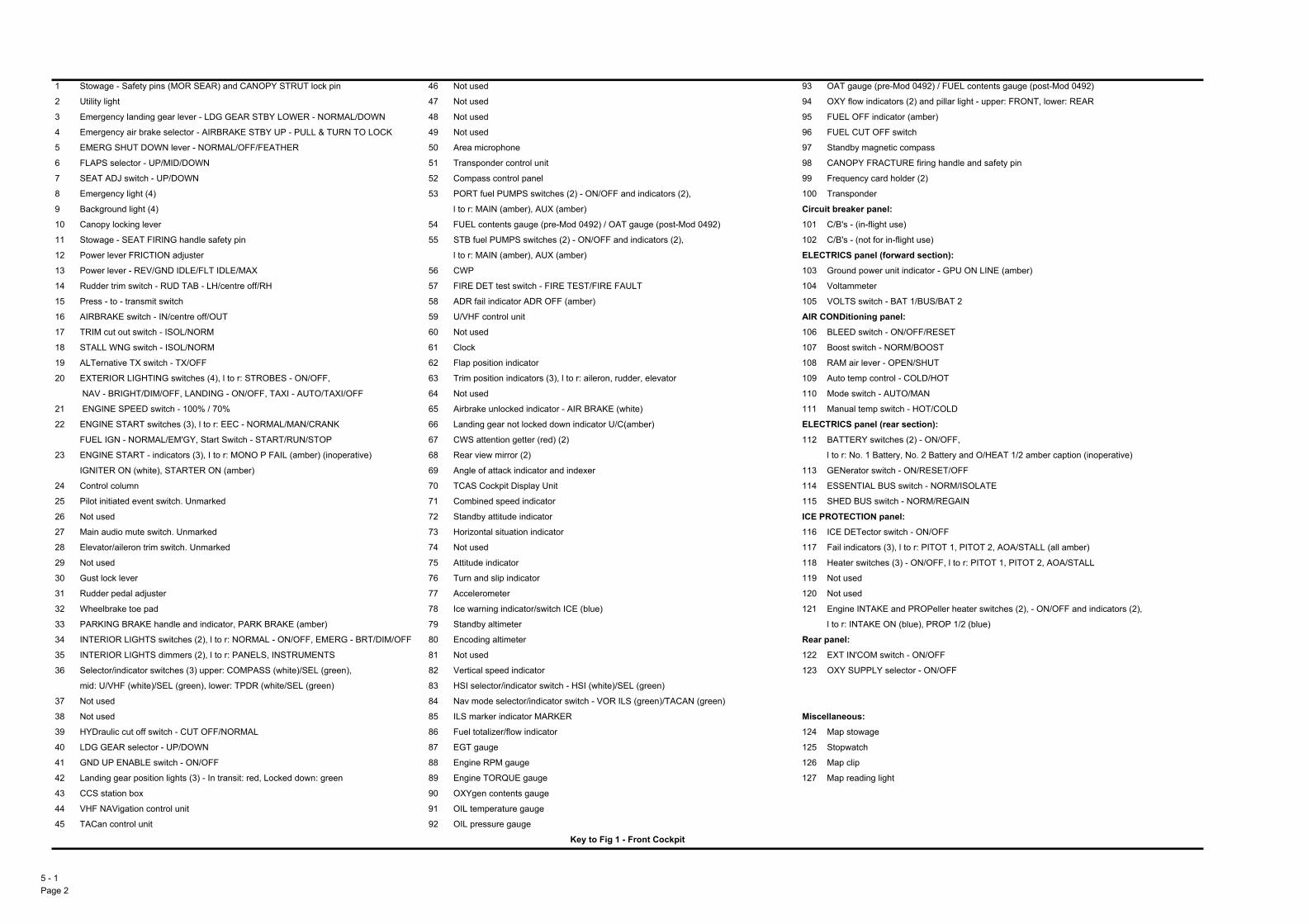
(pre-Mod 0492) / FUEL contents gauge (post-Mod 0492)
dicators (2) and pillar light - upper: FRONT, lower: REAR
ndicator (amber)
OFF switch
gnetic compass
ACTURE firing handle and safety pin
ard holder (2)
r
nel: ight use)
for in-flight use)
l (forward section):er unit indicator - GPU ON LINE (amber)
r
ch - BAT 1/BUS/BAT 2
panel: ch - ON/OFF/RESET
- NORM/BOOST
er - OPEN/SHUT
ontrol - COLD/HOT
- AUTO/MAN
p switch - HOT/COLD
l (rear section): witches (2) - ON/OFF,
Battery, No. 2 Battery and O/HEAT 1/2 amber caption (inoperative)
witch - ON/RESET/OFF
BUS switch - NORM/ISOLATE
switch - NORM/REGAIN
panel: or switch - ON/OFF
rs (3), l to r: PITOT 1, PITOT 2, AOA/STALL (all amber)
hes (3) - ON/OFF, l to r: PITOT 1, PITOT 2, AOA/STALL
KE and PROPeller heater switches (2), - ON/OFF and indicators (2),
E ON (blue), PROP 1/2 (blue)
switch - ON/OFF
Y selector - ON/OFF
e
light
5 - Pag
1 Stowage - Safety pins (MOR SEAR) and CANOPY STRUT lock pin 46 Not used 93 OAT gauge
2 Utility light 47 Not used 94 OXY flow in
3 Emergency landing gear lever - LDG GEAR STBY LOWER - NORMAL/DOWN 48 Not used 95 FUEL OFF i
4 Emergency air brake selector - AIRBRAKE STBY UP - PULL & TURN TO LOCK 49 Not used 96 FUEL CUT
5 EMERG SHUT DOWN lever - NORMAL/OFF/FEATHER 50 Area microphone 97 Standby ma
6 FLAPS selector - UP/MID/DOWN 51 Transponder control unit 98 CANOPY FR
7 SEAT ADJ switch - UP/DOWN 52 Compass control panel 99 Frequency c
8 Emergency light (4) 53 PORT fuel PUMPS switches (2) - ON/OFF and indicators (2), 100 Transponde
9 Background light (4) l to r: MAIN (amber), AUX (amber) Circuit breaker pa10 Canopy locking lever 54 FUEL contents gauge (pre-Mod 0492) / OAT gauge (post-Mod 0492) 101 C/B4s - (in-fl
11 Stowage - SEAT FIRING handle safety pin 55 STB fuel PUMPS switches (2) - ON/OFF and indicators (2), 102 C/B4s - (not
12 Power lever FRICTION adjuster l to r: MAIN (amber), AUX (amber) ELECTRICS pane13 Power lever - REV/GND IDLE/FLT IDLE/MAX 56 CWP 103 Ground pow
14 Rudder trim switch - RUD TAB - LH/centre off/RH 57 FIRE DET test switch - FIRE TEST/FIRE FAULT 104 Voltammete
15 Press - to - transmit switch 58 ADR fail indicator ADR OFF (amber) 105 VOLTS swit
16 AIRBRAKE switch - IN/centre off/OUT 59 U/VHF control unit AIR CONDitioning17 TRIM cut out switch - ISOL/NORM 60 Not used 106 BLEED swit
18 STALL WNG switch - ISOL/NORM 61 Clock 107 Boost switch
19 ALTernative TX switch - TX/OFF 62 Flap position indicator 108 RAM air lev
20 EXTERIOR LIGHTING switches (4), l to r: STROBES - ON/OFF, 63 Trim position indicators (3), l to r: aileron, rudder, elevator 109 Auto temp c
NAV - BRIGHT/DIM/OFF, LANDING - ON/OFF, TAXI - AUTO/TAXI/OFF 64 Not used 110 Mode switch
21 ENGINE SPEED switch - 100% / 70% 65 Airbrake unlocked indicator - AIR BRAKE (white) 111 Manual tem
22 ENGINE START switches (3), l to r: EEC - NORMAL/MAN/CRANK 66 Landing gear not locked down indicator U/C(amber) ELECTRICS paneFUEL IGN - NORMAL/EM4GY, Start Switch - START/RUN/STOP 67 CWS attention getter (red) (2) 112 BATTERY s
23 ENGINE START - indicators (3), I to r: MONO P FAIL (amber) (inoperative) 68 Rear view mirror (2) l to r: No. 1
IGNITER ON (white), STARTER ON (amber) 69 Angle of attack indicator and indexer 113 GENerator s
24 Control column 70 TCAS Cockpit Display Unit 114 ESSENTIAL
25 Pilot initiated event switch. Unmarked 71 Combined speed indicator 115 SHED BUS
26 Not used 72 Standby attitude indicator ICE PROTECTION27 Main audio mute switch. Unmarked 73 Horizontal situation indicator 116 ICE DETect
28 Elevator/aileron trim switch. Unmarked 74 Not used 117 Fail indicato
29 Not used 75 Attitude indicator 118 Heater switc
30 Gust lock lever 76 Turn and slip indicator 119 Not used
31 Rudder pedal adjuster 77 Accelerometer 120 Not used
32 Wheelbrake toe pad 78 Ice warning indicator/switch ICE (blue) 121 Engine INTA
33 PARKING BRAKE handle and indicator, PARK BRAKE (amber) 79 Standby altimeter l to r: INTAK
34 INTERIOR LIGHTS switches (2), l to r: NORMAL - ON/OFF, EMERG - BRT/DIM/OFF 80 Encoding altimeter Rear panel: 35 INTERIOR LIGHTS dimmers (2), l to r: PANELS, INSTRUMENTS 81 Not used 122 EXT IN4COM
36 Selector/indicator switches (3) upper: COMPASS (white)/SEL (green), 82 Vertical speed indicator 123 OXY SUPPL
mid: U/VHF (white)/SEL (green), lower: TPDR (white/SEL (green) 83 HSI selector/indicator switch - HSI (white)/SEL (green)
37 Not used 84 Nav mode selector/indicator switch - VOR ILS (green)/TACAN (green)
38 Not used 85 ILS marker indicator MARKER Miscellaneous: 39 HYDraulic cut off switch - CUT OFF/NORMAL 86 Fuel totalizer/flow indicator 124 Map stowag
40 LDG GEAR selector - UP/DOWN 87 EGT gauge 125 Stopwatch
41 GND UP ENABLE switch - ON/OFF 88 Engine RPM gauge 126 Map clip
42 Landing gear position lights (3) - In transit: red, Locked down: green 89 Engine TORQUE gauge 127 Map reading
43 CCS station box 90 OXYgen contents gauge
44 VHF NAVigation control unit 91 OIL temperature gauge
45 TACan control unit 92 OIL pressure gauge
Key to Fig 1 - Front Cockpit
1e 2

AP 101B-4901-15 1st EditionAircraft Illustrations
94
6
97
8
103
109
110 111
8
117
122
124
123
102107
101
121
9
9
105
113
114
116
2
99
12
8
115
118
99
58
57
98
5 - 1Page 3
Front Cockpit
5 - 1 Fig 1 Front Cockpit
9
125
68
629
68
3953 55
34
27
25
24
17
14
12
11
9
127 127
126
28
106
1
10
77
69
1
8
8
4
7
6
1013
15
19
22
18
21 23
20
32 32
30
35
31
36
33
54
514544
41
5652504342
7259
61
63
6566
67 76 78
82
83 84 85
67
89
88
87
9386
95
104
40
90
92
91
5
75
80
79
71
3
16
73
100
70

QUE gauge
tents gauge
ture gauge
e gauge
(pre-Mod 0492) / FUEL contents gauge (post-Mod 0492)
dicators (2) and pillar light - upper: FRONT, lower: REAR
ndicator (amber)
OFF switch - CLOSE/FRONT/OPEN
gnetic compass
ACTURE firing handle and safety pin
ard holder (2)
r
l: er unit indicator - GPU ON LINE (amber)
r
ch - BAT 1/BUS/BAT
witches (2) - ON/FRONT/OFF,
Battery, No. 2 Battery and O/HEAT 1/2 amber caption (inoperative)
witch - ON/RESET/OFF
switch - NORM/REGAIN
BUS switch - NORM/ISOLATE
nel: for in-flight use)
panel: or switch - ON/OFF
rs (3), l to r: PITOT 1, PITOT 2, AOA/STALL (all amber)
hes (2) - ON/OFF, l to r: PITOT 1, PITOT 2
KE and PROPeller heater switches (2), - ON/FRONT/OFF
rs (2), l to r: INTAKE ON (blue), PROP 1/2 (blue)
heater switch (3) - ON/FRONT/OFF
switch - ON/OFF
Y selector - ON/OFF
e
light
5 - Pag
1 Utility light 41 Not used 82 Engine TOR
2 Emergency landing gear lever - LDG GEAR STBY LOWER - NORMAL/DOWN 42 Not used 83 OXYgen con
3 EMERG SHUT DOWN lever - NORMAL/OFF/FEATHER 43 Not used 84 OIL tempera
4 FLAPS selector - UP/MID/DOWN 44 Area microphone 85 OIL pressur
5 SEAT ADJ switch - UP/DOWN 45 Transponder control unit 86 OAT gauge
6 Emergency light (4) 46 Compass control panel 87 OXY flow in
7 Background light (4) 47 PORT fuel PUMPS switches (2) - ON/OFF and indicators (2), 88 FUEL OFF i
8 Canopy locking lever l to r: MAIN (amber), AUX (amber) 89 FUEL CUT
9 Stowage - SEAT FIRING handle safety pin 48 FUEL contents gauge (pre-Mod 0492) / OAT gauge (post-Mod 0492) 90 Standby ma
10 Power lever - REV/GND IDLE/FLT IDLE/MAX 49 STB fuel PUMPS switches (2) - ON/OFF and indicators (2), 91 CANOPY FR
11 Rudder trim switch RUD TAB - LH/centre off/RH l to r: MAIN (amber), AUX (amber) 92 Frequency c
12 Press - to - transmit switch 50 CWP 93 Transponde
13 AIRBRAKE switch - IN/centre off/OUT 51 FIRE DET test switch - FIRE TEST/FIRE FAULT ELECTRICS pane14 ALTernative MUTE switch - MUTE/NORMAL 52 U/VHF control unit 94 Ground pow
15 TRIM cut out switch - ISOL/NORM 53 Remote frequency channel indicator 95 Voltammete
16 STALL WNG switch - ISOL/NORM 54 Not used 96 VOLTS swit
17 ALTernative TX switch - TX/OFF 55 Flap position indicator 97 BATTERY s
18 ENGINE SPEED switch - 100% / 70% 56 Trim position indicators (3), l to r: aileron, rudder, elevator l to r: No. 1
19 ENGINE START switches (3), l to r: EEC - NORMAL/MAN/CRANK, 57 Not used 98 GENerator s
FUEL IGN - NORMAL/EM4GY, Start Switch - START/RUN/STOP 58 Airbrake unlocked indicator - AIR BRAKE (white) 99 SHED BUS
20 ENGINE START indicators (3), l to r: MONO P FAIL (amber) (inoperative), 59 Landing gear not locked down indicator - U/C(amber) 100 ESSENTIAL
IGNITER ON (white), STARTER ON (amber) 60 Rear view mirror (2) Circuit breaker pa21 MASTER ENG SW - FRONT/REAR 61 Angle of attack indicator and indexer 101 C/B4s - (not
22 Control column 62 Not used ICE PROTECTION23 Inactive switch (not used) 63 CWS attention getter (red) (2) 102 ICE DETect
24 Main audio mute switch. Unmarked 64 TCAS Cockpit Display Unit 103 Fail indicato
25 Elevator/aileron trim switch. Unmarked 65 Combined speed indicator 104 Not used
26 Rudder pedal adjuster 66 Standby attitude indicator 105 Heater switc
27 Wheelbrake toe pad 67 Horizontal situation indicator 106 Engine INTA
28 PARKING BRAKE handle and indicator - PARK BRAKE (amber) 68 Not used and indicato
29 INTERIOR LIGHTS switches (2), l to r: NORMAL - ON/OFF, EMERG - BRT/DIM/OFF 69 Attitude indicator 107 AOA/STALL
30 INTERIOR LIGHTS dimmers (2), l to r: PANELS, INSTRUMENTS 70 Turn and slip indicator 108 Not used
31 Selector/indicator switches (3) upper: COMPASS (white)/SEL (green) 71 Accelerometer Rear panel: mid: U/VHF (white)/SEL (green), lower: TPDR (white/SEL (green) 72 Ice warning indicator/switch ICE (blue) 109 EXT IN4COM
32 Not used 73 Standby altimeter 110 OXY SUPPL
33 Not used 74 Servo altimeter
34 HYDraulic cut off switch - CUT OFF/NORMAL 75 Vertical speed indicator Miscellaneous: 35 LDG GEAR selector - UP/DOWN 76 HSI selector/indicator switch - HSI (white)/SEL (green) 111 Map stowag
36 GND UP ENABLE switch - ON/OFF 77 Nav mode selector/indicator switch - VOR ILS (green)/TACAN (green) 112 Stopwatch
37 Landing gear position lights (3) - In transit: red, Locked down: green 78 ILS marker indicator MARKER 113 Map clip
38 CCS station box 79 Fuel totalizer/flow indicator 114 Map reading
39 VHF NAVigation control unit 80 EGT gauge
40 TACan control unit 81 Engine RPM gauge
Key to Fig 2 - Rear Cockpit
1e 4

AP 101B-4901-15 1st EditionAircraft Illustrations
51
60
83
84
85
87
89
90
49
6
99100
105
106
111
7
7
114
86
88
95
94
96
9798
101
102103
107109
110
6
92
91
1
93
5 - 1Page 5
Rear Cockpit
5 - 1 Fig 2 Rear Cockpit
5860
114
59
61
72
76 77 78
71
113112
3744
31
28
24
23
22
47
21
11
10
6
9
6
3
2
5
7
8
7
13
18
17161514
19 26
30
45
29
38
39 40
36
35
34
6775 80
81
8269
66
65
64
63 6370
52
53
50
48
46
4
79
73
74
12
20
25
55
56
2727

Intentionally Blank
5 - 1Page 6

AP 101B-4901-15 1st EditionAircraft Illustrations
External Checks Front
No
2 B
att I
nlet
Val
ve
5 - 1 Fig 3 External Checks Front
5 - 1Page 7

External Checks Rear
5 - Pag
No
1 B
att
Ven
t
OA
T S
enso
r
UH
F A
eria
l
5 - 1 Fig 4 External Checks Rear
No
2 B
att
Ven
t
1e 8