1wmpd4002746b - valley microscope · the balance has a counting function, ... wind shield cap...
TRANSCRIPT
1WMPD4002746B

This Manual and Marks All safety messages are identified by the following, “WARNING” or “CAUTION”, of ANSI
Z535.4 (American National Standard Institute: Product Safety Signs and Labels). The
meanings are as follows:
WARNING A potentially hazardous situation, which if not avoided, could result
in death or serious injury.
CAUTION A potentially hazardous situation, which if not avoided, may result
in minor or moderate injury.
This is a hazard alert mark.
Note This manual is subject to change without notice at any time to improve the product. No
part of this manual may be photocopied, reproduced, or translated into another language
without the prior written consent of the A&D Company.
Product specifications are subject to change without any obligation on the part of the
manufacturer.
Compliance with FCC rules Please note that this equipment generates, uses and can radiate radio frequency energy.
This equipment has been tested and has been found to comply with the limits of a Class
A computing device pursuant to Subpart J of Part 15 of FCC rules. These rules are
designed to provide reasonable protection against interference when the equipment is
operated in a commercial environment. If this unit is operated in a residential area it may
cause some interference and under these circumstances the user would be required to
take, at his own expense, whatever measures are necessary to eliminate the
interference.
(FCC = Federal Communications Commission in the U.S.A.)
Copyright 2015
Microsoft, Excel and Word are trademarks of Microsoft Corporation.
1
CONTENTS
1. INTRODUCTION....................................................................................................................3
2. UNPACKING...........................................................................................................................3
3. PART NAMES AND FUNCTIONS .........................................................................................4
4. SETTING UP ..........................................................................................................................6 4.1. Setting Up Your Balance...............................................................................................6 4.2. Power Source ...............................................................................................................7 4.3. Breeze Break ................................................................................................................8
5. OPERATION...........................................................................................................................9 5.1. Turn The Power ON And OFF......................................................................................9 5.2. LCD Backlight ...............................................................................................................9 5.3. Units ............................................................................................................................10 5.4. Selecting A Weighing Unit...........................................................................................10 5.5. Basic Operation .......................................................................................................... 11 5.6. Display Hold Mode...................................................................................................... 11 5.7. Counting Mode (pcs) ..................................................................................................12 5.8. Percent Mode (%).......................................................................................................13
6. ACCUMULATION FUNCTION.............................................................................................14
7. CALIBRATION......................................................................................................................16 7.1. Calibration Using A Weight .........................................................................................16 7.2. Gravity Acceleration Correction..................................................................................17
8. FUNCTIONS.........................................................................................................................18 8.1. Key Operation.............................................................................................................18 8.2. Entering The Function Setting Mode..........................................................................18 8.3. Setting Example..........................................................................................................19 8.4. Storing Weighing Units ...............................................................................................20 8.5. Function List................................................................................................................21
9. OPTIONS..............................................................................................................................23 9.1. EJ-02 USB Interface...................................................................................................23 9.2. EJ-03 RS-232C Serial Interface.................................................................................24 9.3. Data Format ................................................................................................................25 9.4. EJ-13 Density Determination Kit ................................................................................27
10. ID NUMBER AND GLP.........................................................................................................30 10.1. Setting The ID Number............................................................................................30 10.2. GLP Report..............................................................................................................31
11. MAINTENANCE ...................................................................................................................35 11.1. Notes On Maintenance ...........................................................................................35 11.2. Error Codes .............................................................................................................35
2
12. SPECIFICATIONS................................................................................................................37 12.1. Generals ..................................................................................................................37 12.2. Weighing Units.........................................................................................................37 12.3. Options ....................................................................................................................38 12.4. Dimensions..............................................................................................................38
13. GRAVITY ACCELERATION MAP........................................................................................39
3
Protective film
1. INTRODUCTION
This manual describes how this balance works and how to get the most out of it in terms of performance. The EJ-123 and EJ-303 compact precision balance has the following features:
The balance is high-resolution type electronic balance having a display resolution of 1/120,000 to 1/300,000.
The balance has a counting function, a percent function, a hold function and a total function.
The LCD backlight will help with use in a dimly lighted place.
The balance can be operated with an AC adapter, or 4 x “AA” size dry-cell batteries for cordless operation.
The optional RS-232C serial interface can be connected with a printer or personal computer, and Good Laboratory Practice (GLP) data can be obtained.
The optional USB interface is available for connection to a personal computer.
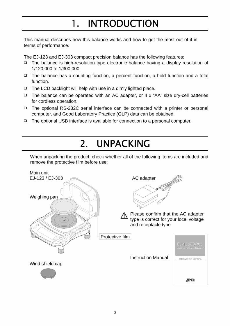
2. UNPACKING
When unpacking the product, check whether all of the following items are included and remove the protective film before use: Main unit EJ-123 / EJ-303 AC adapter
Weighing pan
Please confirm that the AC adapter type is correct for your local voltage and receptacle type
Instruction Manual Wind shield cap
4
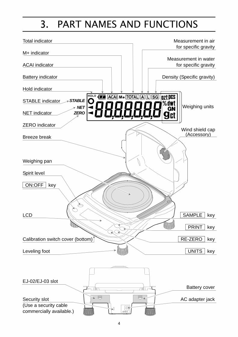
3. PART NAMES AND FUNCTIONS
Total indicator Measurement in air for specific gravity M+ indicator Measurement in water ACAI indicator for specific gravity Battery indicator Density (Specific gravity) Hold indicator STABLE indicator NET indicator ZERO indicator Breeze break Weighing pan Spirit level ON:OFF key LCD SAMPLE key PRINT key Calibration switch cover (bottom) RE-ZERO key Leveling foot UNITS key EJ-02/EJ-03 slot Battery cover Security slot AC adapter jack (Use a security cable commercially available.)
STABLE
NET ZERO
Weighing units
Wind shield cap(Accessory)
5
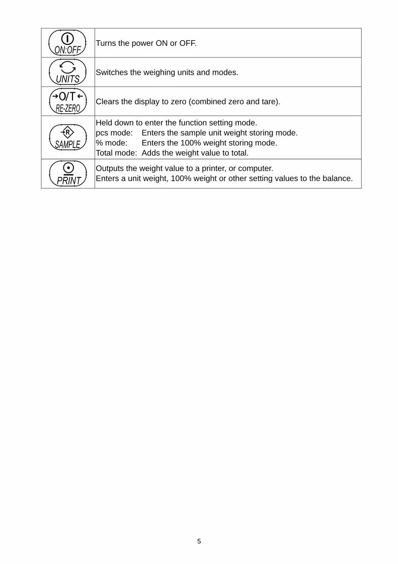
Turns the power ON or OFF.
Switches the weighing units and modes.
Clears the display to zero (combined zero and tare).
Held down to enter the function setting mode. pcs mode: Enters the sample unit weight storing mode. % mode: Enters the 100% weight storing mode. Total mode: Adds the weight value to total.
Outputs the weight value to a printer, or computer. Enters a unit weight, 100% weight or other setting values to the balance.
6
4. SETTING UP
4.1. Setting Up Your Balance 1. Place the weighing pan on the main unit. 2. Adjust the level of the balance using the leveling feet. Use the spirit level to confirm.
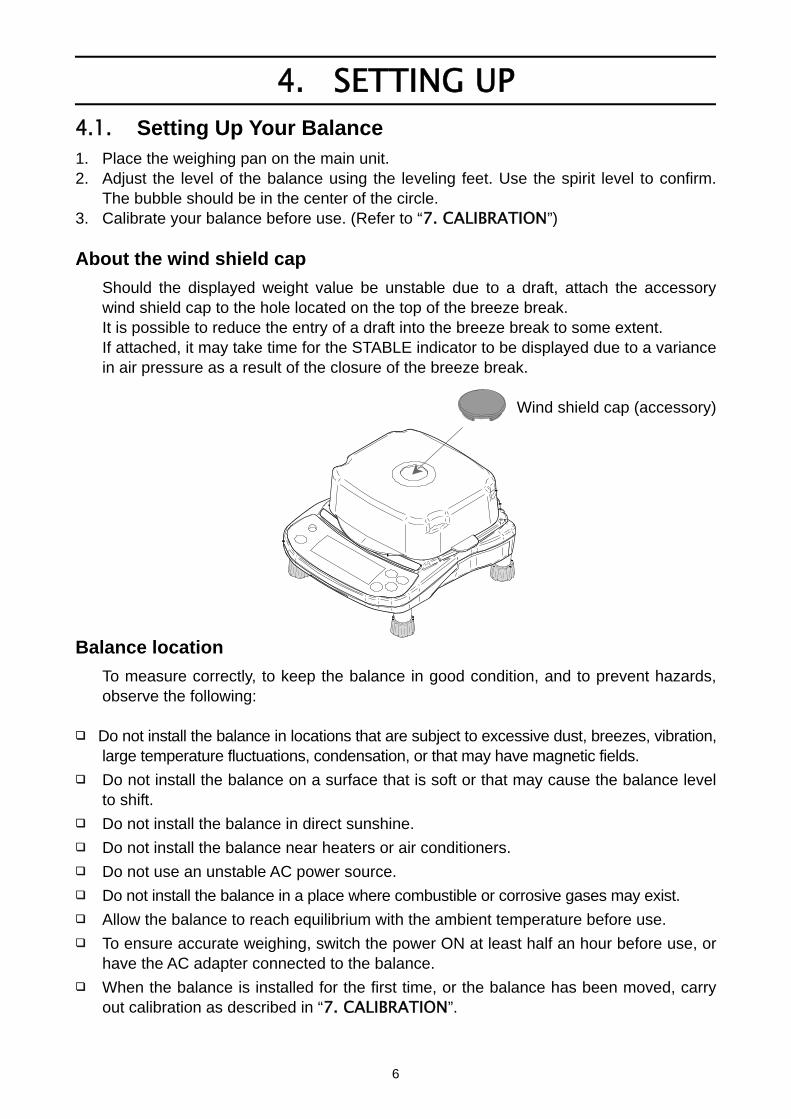
The bubble should be in the center of the circle. 3. Calibrate your balance before use. (Refer to “7. CALIBRATION”) About the wind shield cap
Should the displayed weight value be unstable due to a draft, attach the accessory wind shield cap to the hole located on the top of the breeze break. It is possible to reduce the entry of a draft into the breeze break to some extent. If attached, it may take time for the STABLE indicator to be displayed due to a variance in air pressure as a result of the closure of the breeze break.
Wind shield cap (accessory)
Balance location
To measure correctly, to keep the balance in good condition, and to prevent hazards, observe the following:
Do not install the balance in locations that are subject to excessive dust, breezes, vibration, large temperature fluctuations, condensation, or that may have magnetic fields.
Do not install the balance on a surface that is soft or that may cause the balance level to shift.
Do not install the balance in direct sunshine.
Do not install the balance near heaters or air conditioners.
Do not use an unstable AC power source.
Do not install the balance in a place where combustible or corrosive gases may exist.
Allow the balance to reach equilibrium with the ambient temperature before use.
To ensure accurate weighing, switch the power ON at least half an hour before use, or have the AC adapter connected to the balance.
When the balance is installed for the first time, or the balance has been moved, carry out calibration as described in “7. CALIBRATION”.
7
4.2. Power Source For the power source, the AC adapter or 4 x “AA” size dry-cell batteries can be used.
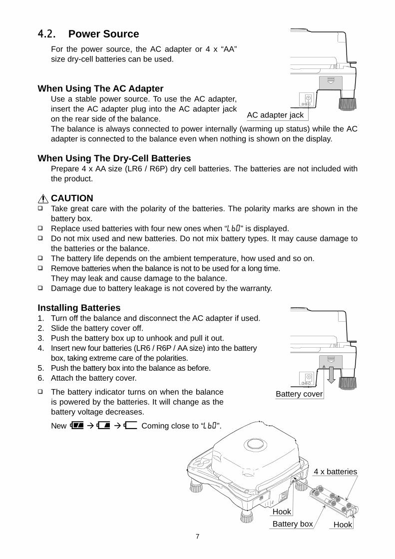
When Using The AC Adapter Use a stable power source. To use the AC adapter, insert the AC adapter plug into the AC adapter jack on the rear side of the balance. The balance is always connected to power internally (warming up status) while the AC adapter is connected to the balance even when nothing is shown on the display.
When Using The Dry-Cell Batteries Prepare 4 x AA size (LR6 / R6P) dry cell batteries. The batteries are not included with the product. CAUTION
Take great care with the polarity of the batteries. The polarity marks are shown in the battery box.
Replace used batteries with four new ones when “lb0” is displayed. Do not mix used and new batteries. Do not mix battery types. It may cause damage to
the batteries or the balance. The battery life depends on the ambient temperature, how used and so on. Remove batteries when the balance is not to be used for a long time.
They may leak and cause damage to the balance. Damage due to battery leakage is not covered by the warranty.
Installing Batteries 1. Turn off the balance and disconnect the AC adapter if used. 2. Slide the battery cover off. 3. Push the battery box up to unhook and pull it out. 4. Insert new four batteries (LR6 / R6P / AA size) into the battery
box, taking extreme care of the polarities. 5. Push the battery box into the balance as before. 6. Attach the battery cover.
The battery indicator turns on when the balance is powered by the batteries. It will change as the battery voltage decreases.
New Coming close to “lb0”.
AC adapter jack
Battery cover
4 x batteries
Battery box
Hook
Hook
8
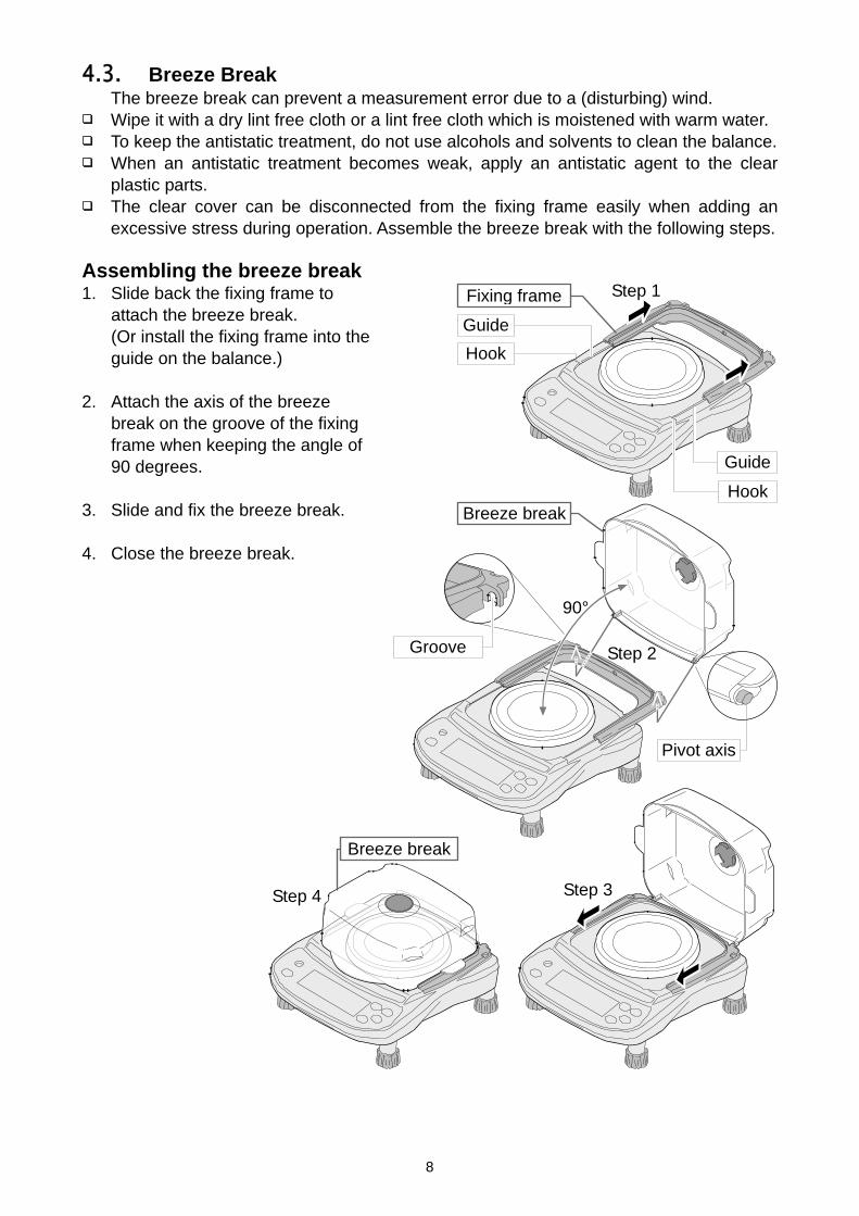
4.3. Breeze Break The breeze break can prevent a measurement error due to a (disturbing) wind.
Wipe it with a dry lint free cloth or a lint free cloth which is moistened with warm water. To keep the antistatic treatment, do not use alcohols and solvents to clean the balance. When an antistatic treatment becomes weak, apply an antistatic agent to the clear
plastic parts. The clear cover can be disconnected from the fixing frame easily when adding an
excessive stress during operation. Assemble the breeze break with the following steps. Assembling the breeze break 1. Slide back the fixing frame to
attach the breeze break. (Or install the fixing frame into the guide on the balance.)
2. Attach the axis of the breeze
break on the groove of the fixing frame when keeping the angle of 90 degrees.
3. Slide and fix the breeze break. 4. Close the breeze break.
Pivot axis
Fixing frame
Breeze break
Step 1
Step 3
Step 2
90°
Step 4
Breeze break
Hook
Hook
Groove
Guide
Guide

9
5. OPERATION
5.1. Turn The Power ON And OFF 1. Press the ON:OFF key to turn the power ON.
All of the symbols are displayed as shown above. (About units: Only the available units will be displayed.)
When the scale is operating using dry-cell batteries, the scale performs count a down using the under-bar on the display.
The display turns off except for a weighing unit and the decimal point. The balance waits for the weight value to become stable, and then, zero will be
displayed with the ZERO indicator (power-on zero). The range for power-on zero is within ±50% of the weighing capacity around the
calibrated zero point. If the power is switched ON while there is a load beyond this range, the balance will be
tared to zero and the NET indicator and the ZERO indicator turn on. 2. Press the ON:OFF key again, and the power will be switched OFF.
Auto-power off function
It is possible to have the power automatically switched OFF, if the zero band display (band width: ±4 digit from the zero point) continues for approximately 5 minutes. Refer to “8.5. Function List” and set the function to “poff”.
5.2. LCD Backlight
The LCD backlight will turn on when the weight value changes more than 4d (4 x min. display division) or any key operation is done. When the weight value becomes and stays stable for some moments, the backlight will automatically turn off. There is also a setting that the backlight is always on or off. For details, see the function setting “ltUp” of “8.5. Function list”.
STABLE
NET
ZERO
Weighing units
10
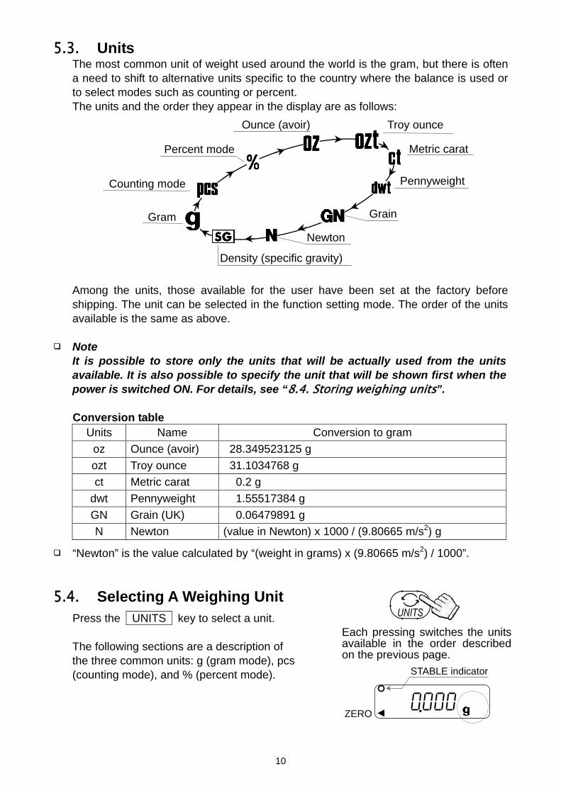
5.3. Units The most common unit of weight used around the world is the gram, but there is often
a need to shift to alternative units specific to the country where the balance is used or to select modes such as counting or percent.
The units and the order they appear in the display are as follows: Among the units, those available for the user have been set at the factory before
shipping. The unit can be selected in the function setting mode. The order of the units available is the same as above.
Note
It is possible to store only the units that will be actually used from the units available. It is also possible to specify the unit that will be shown first when the power is switched ON. For details, see “8.4. Storing weighing units”.
Conversion table
Units Name Conversion to gram
oz Ounce (avoir) 28.349523125 g
ozt Troy ounce 31.1034768 g
ct Metric carat 0.2 g
dwt Pennyweight 1.55517384 g
GN Grain (UK) 0.06479891 g
N Newton (value in Newton) x 1000 / (9.80665 m/s2) g
“Newton” is the value calculated by “(weight in grams) x (9.80665 m/s2) / 1000”.
5.4. Selecting A Weighing Unit Press the UNITS key to select a unit. The following sections are a description of
the three common units: g (gram mode), pcs (counting mode), and % (percent mode).
Density (specific gravity)
Gram
Counting mode
Percent mode
Ounce (avoir)
Metric carat
Pennyweight
Grain
Newton
Troy ounce
0.000 ZERO
Each pressing switches the unitsavailable in the order describedon the previous page.
STABLE indicator
11
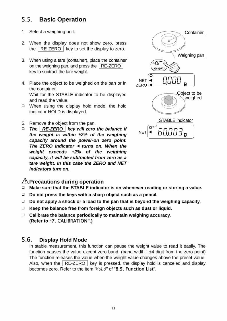
5.5. Basic Operation
1. Select a weighing unit. 2. When the display does not show zero, press
the RE-ZERO key to set the display to zero. 3. When using a tare (container), place the container
on the weighing pan, and press the RE-ZERO key to subtract the tare weight.
4. Place the object to be weighed on the pan or in
the container. Wait for the STABLE indicator to be displayed and read the value.
When using the display hold mode, the hold indicator HOLD is displayed.
5. Remove the object from the pan.
The RE-ZERO key will zero the balance if the weight is within ±2% of the weighing capacity around the power-on zero point. The ZERO indicator turns on. When the weight exceeds +2% of the weighing capacity, it will be subtracted from zero as a tare weight. In this case the ZERO and NET indicators turn on.
Precautions during operation
Make sure that the STABLE indicator is on whenever reading or storing a value.
Do not press the keys with a sharp object such as a pencil.
Do not apply a shock or a load to the pan that is beyond the weighing capacity.
Keep the balance free from foreign objects such as dust or liquid.
Calibrate the balance periodically to maintain weighing accuracy. (Refer to “7. CALIBRATION”.)
5.6. Display Hold Mode In stable measurement, this function can pause the weight value to read it easily. The
function pauses the value except zero band. (band width : ±4 digit from the zero point) The function releases the value when the weight value changes above the preset value. Also, when the RE-ZERO key is pressed, the display hold is canceled and display becomes zero. Refer to the item "Hold" of "8.5. Function List".
Container
Weighing pan
0.000 NET ZERO
060.003 NET
STABLE indicator
Object to beweighed
12
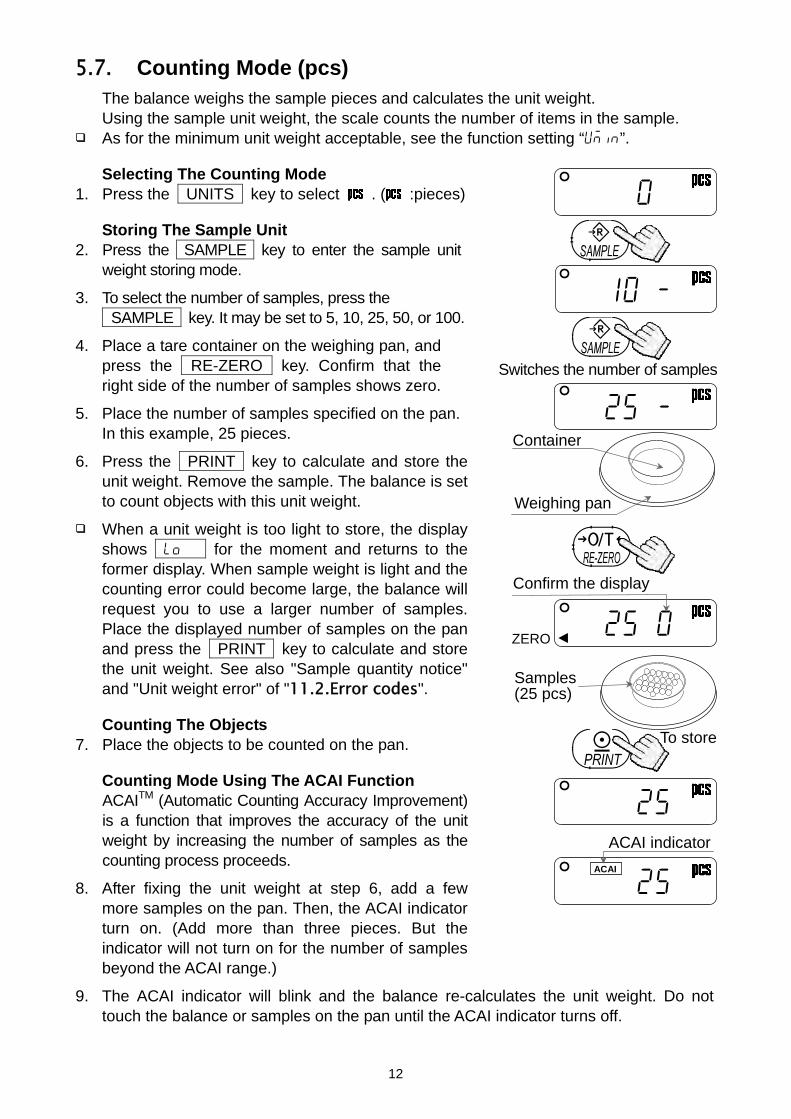
5.7. Counting Mode (pcs) The balance weighs the sample pieces and calculates the unit weight.
Using the sample unit weight, the scale counts the number of items in the sample. As for the minimum unit weight acceptable, see the function setting “Umin”.
Selecting The Counting Mode 1. Press the UNITS key to select . ( :pieces)
Storing The Sample Unit 2. Press the SAMPLE key to enter the sample unit
weight storing mode.
3. To select the number of samples, press the 1SAMPLE key. It may be set to 5, 10, 25, 50, or 100.
4. Place a tare container on the weighing pan, and press the RE-ZERO key. Confirm that the right side of the number of samples shows zero.
5. Place the number of samples specified on the pan. In this example, 25 pieces.
6. Press the PRINT key to calculate and store the unit weight. Remove the sample. The balance is set to count objects with this unit weight.
When a unit weight is too light to store, the display shows lo for the moment and returns to the former display. When sample weight is light and the counting error could become large, the balance will request you to use a larger number of samples. Place the displayed number of samples on the pan and press the PRINT key to calculate and store the unit weight. See also "Sample quantity notice" and "Unit weight error" of "11.2.Error codes".
Counting The Objects 7. Place the objects to be counted on the pan.
Counting Mode Using The ACAI Function ACAITM (Automatic Counting Accuracy Improvement)
is a function that improves the accuracy of the unit weight by increasing the number of samples as the counting process proceeds.
8. After fixing the unit weight at step 6, add a few more samples on the pan. Then, the ACAI indicator turn on. (Add more than three pieces. But the indicator will not turn on for the number of samples beyond the ACAI range.)
9. The ACAI indicator will blink and the balance re-calculates the unit weight. Do not touch the balance or samples on the pan until the ACAI indicator turns off.
Weighing pan
0
10 -
25 - Container
25 ACAI indicator
ACAI
25
Confirm the display
25 0 ZERO
Switches the number of samples
Samples (25 pcs)
To store

13
10. Counting accuracy is improved when the ACAI indicator turns off. Each time the above operation is performed, a more accurate unit weight will be obtained. There is no definite upper limit of ACAI range for the number of samples exceeding 100. Try to add a similar number of samples as that displayed.
5.8. Percent Mode (%) Displays the weight value in percentage compared to a reference (100%) weight.
Selecting The Percent Mode 1. Press the UNITS key to select %. (%:percent)
Storing The Reference (100%) Weight 2. Press the SAMPLE key to enter the reference
weight storing mode. 3. Press the RE-ZERO key to display 100 0%. 4. Place the sample to be set as the reference weight
on the pan. 5. Press the PRINT key to store the reference
weight. Remove the sample.
When a unit weight is too light to store, the display shows for the moment and returns to the former display.
Reading The Percentage 6. Place the object to be compared to the reference
weight on the pan. The displayed percentage is based on 100% of the reference weight.
To store
0.0 %
100 - %
100.0 %
75.8 %
100 0 %ZERO
Weighing pan
Sample corresponding to the 100% weight
Object to be compared

14
6. ACCUMULATION FUNCTION
This function counts the number of times articles are weighed, calculates the total mass value and can display the number (accumulation count) and accumulated mass value.
Preset the item "Hold" of the function list to use the accumulation function. The accumulation count and accumulated mass value are stored in the scale even if
the power is removed. Indicators And Keys
The indicator is displayed when storing the accumulation data. The indicator and is displayed when displaying the accumulated count and
accumulated mass. Operation keys as follows :
The UNITS key When storing the accumulation data and pressing the UNITS key, the current
weight value, the accumulated count and accumulated mass value are displayed sequentially.
When the accumulation data is not stored, the UNITS key switches the preset units sequentially.
The RE-ZERO key
When displaying the weight value and pressing the RE-ZERO key, zero is displayed.
While displaying the accumulated count and accumulated mass, when pressing the RE-ZERO key, the accumulation data is reset to the zero.
The SAMPLE key
The condition of the accumulation function is as follows : When a stable weight value is above ±5 digits from zero band. The accumulated count is less than 1000. The accumulated mass value is less than 9999999.
The unit weight of the counting mode and the reference (100%) weight of the percent
mode can not store when using the accumulation function.
15
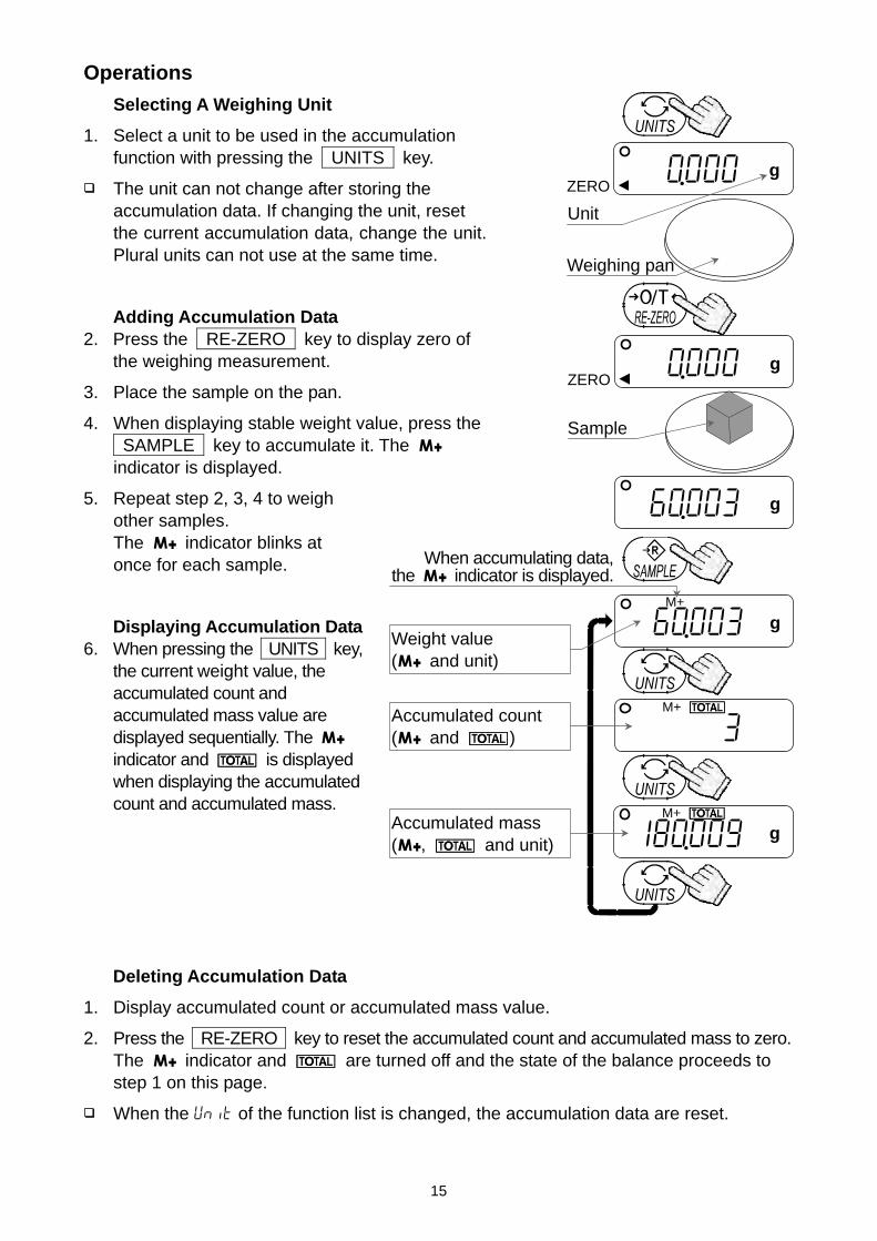
Operations
Selecting A Weighing Unit
1. Select a unit to be used in the accumulation function with pressing the UNITS key.
The unit can not change after storing the accumulation data. If changing the unit, reset the current accumulation data, change the unit. Plural units can not use at the same time.
Adding Accumulation Data 2. Press the RE-ZERO key to display zero of
the weighing measurement.
3. Place the sample on the pan.
4. When displaying stable weight value, press the SAMPLE key to accumulate it. The indicator is displayed.
5. Repeat step 2, 3, 4 to weigh other samples. The indicator blinks at once for each sample.
Displaying Accumulation Data 6. When pressing the UNITS key,
the current weight value, the accumulated count and accumulated mass value are displayed sequentially. The indicator and is displayed when displaying the accumulated count and accumulated mass.
Deleting Accumulation Data
1. Display accumulated count or accumulated mass value.
2. Press the RE-ZERO key to reset the accumulated count and accumulated mass to zero. The indicator and are turned off and the state of the balance proceeds to step 1 on this page.
When the Unit of the function list is changed, the accumulation data are reset.
0.000 g ZERO
Sample
Weighing pan
0.000 g ZERO
Unit
60.003 g
060.003 g M+
When accumulating data,the indicator is displayed.
3 M+
180.009 g M+
Weight value ( and unit)
Accumulated count ( and )
Accumulated mass ( , and unit)
16
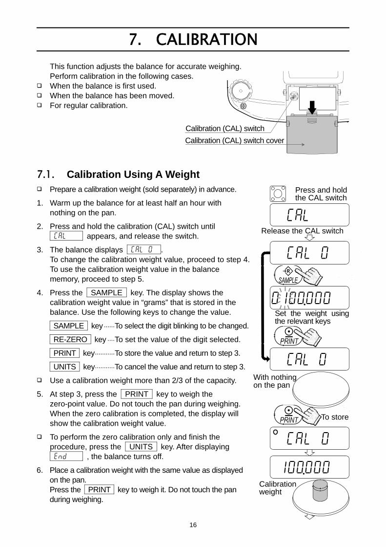
7. CALIBRATION
This function adjusts the balance for accurate weighing. Perform calibration in the following cases.
When the balance is first used. When the balance has been moved. For regular calibration.
7.1. Calibration Using A Weight Prepare a calibration weight (sold separately) in advance.
1. Warm up the balance for at least half an hour with nothing on the pan.
2. Press and hold the calibration (CAL) switch until Cal appears, and release the switch.
3. The balance displays Cal 0 . To change the calibration weight value, proceed to step 4. To use the calibration weight value in the balance memory, proceed to step 5.
4. Press the SAMPLE key. The display shows the calibration weight value in “grams” that is stored in the balance. Use the following keys to change the value.
SAMPLE key ......To select the digit blinking to be changed.
RE-ZERO key ....To set the value of the digit selected.
PRINT key...........To store the value and return to step 3.
UNITS key...........To cancel the value and return to step 3.
Use a calibration weight more than 2/3 of the capacity.
5. At step 3, press the PRINT key to weigh the zero-point value. Do not touch the pan during weighing. When the zero calibration is completed, the display will show the calibration weight value.
To perform the zero calibration only and finish the procedure, press the UNITS key. After displaying end , the balance turns off.
6. Place a calibration weight with the same value as displayed on the pan. Press the PRINT key to weigh it. Do not touch the pan during weighing.
Calibration (CAL) switch
Calibration (CAL) switch cover
Cal
Cal 0
0100.000
Cal 0
Set the weight using the relevant keys
Release the CAL switch
Press and holdthe CAL switch
With nothing on the pan
To store
Calibration weight
Cal 0
100.000
17
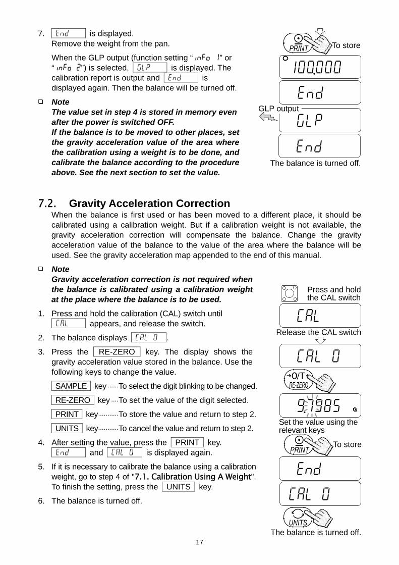
7. end is displayed. Remove the weight from the pan.
When the GLP output (function setting “info 1” or “info 2”) is selected, glp is displayed. The calibration report is output and end is displayed again. Then the balance will be turned off.
Note The value set in step 4 is stored in memory even after the power is switched OFF.
If the balance is to be moved to other places, set the gravity acceleration value of the area where the calibration using a weight is to be done, and calibrate the balance according to the procedure above. See the next section to set the value.
7.2. Gravity Acceleration Correction When the balance is first used or has been moved to a different place, it should be
calibrated using a calibration weight. But if a calibration weight is not available, the gravity acceleration correction will compensate the balance. Change the gravity acceleration value of the balance to the value of the area where the balance will be used. See the gravity acceleration map appended to the end of this manual.
Note Gravity acceleration correction is not required when
the balance is calibrated using a calibration weight at the place where the balance is to be used.
1. Press and hold the calibration (CAL) switch until Cal appears, and release the switch.
2. The balance displays Cal 0 .
3. Press the RE-ZERO key. The display shows the gravity acceleration value stored in the balance. Use the following keys to change the value.
SAMPLE key ......To select the digit blinking to be changed.
RE-ZERO key ....To set the value of the digit selected.
PRINT key...........To store the value and return to step 2.
UNITS key...........To cancel the value and return to step 2.
4. After setting the value, press the PRINT key. end and Cal 0 is displayed again.
5. If it is necessary to calibrate the balance using a calibration weight, go to step 4 of "7.1. Calibration Using A Weight". To finish the setting, press the UNITS key.
6. The balance is turned off.
Cal
Cal 0
9.7985
Cal 0
The balance is turned off.
Release the CAL switch
Set the value using the relevant keys
Press and holdthe CAL switch
end
To store
100.000
0end000
To store
The balance is turned off.
glp GLP output
end000
18
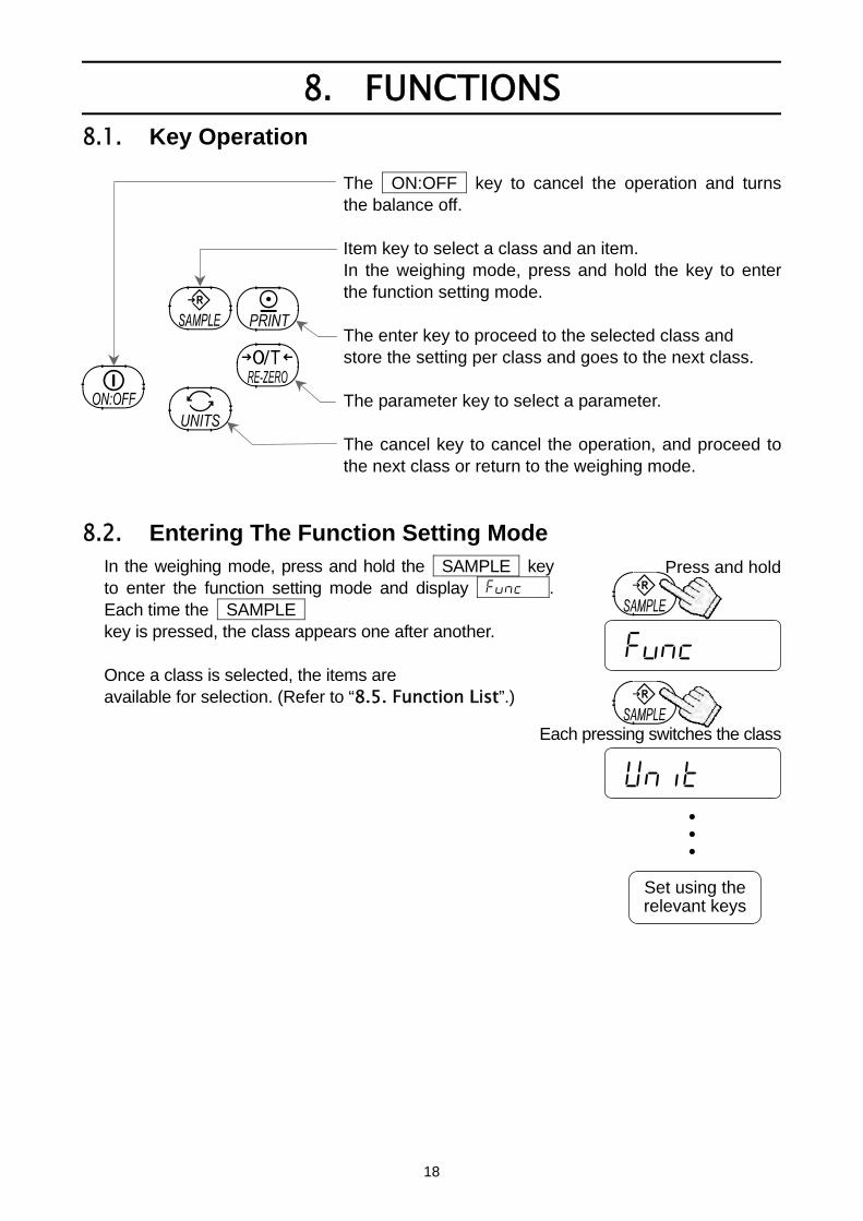
8. FUNCTIONS 8.1. Key Operation
The ON:OFF key to cancel the operation and turns the balance off. Item key to select a class and an item. In the weighing mode, press and hold the key to enter the function setting mode. The enter key to proceed to the selected class and store the setting per class and goes to the next class. The parameter key to select a parameter. The cancel key to cancel the operation, and proceed to the next class or return to the weighing mode.
8.2. Entering The Function Setting Mode In the weighing mode, press and hold the SAMPLE key to enter the function setting mode and display func . Each time the SAMPLE key is pressed, the class appears one after another. Once a class is selected, the items are available for selection. (Refer to “8.5. Function List”.)
func
Unit
Press and hold
Each pressing switches the class
Set using therelevant keys
• • •

19
8.3. Setting Example
To set auto power-off function to “Enabled”, and the ACAI function to “Disabled”. 1. Press and hold the SAMPLE key to display func . 2. Press the PRINT key. The balance displays poff 0 . 3. Press the RE-ZERO key to display poff 1 . 4. Press the SAMPLE key several times to display
aCai 1 . 5. Press the RE-ZERO key to select aCai 0 . 6. Press the PRINT key to store the parameters.
Unit appears after end . 7. Press the UNITS key to turn off the balance.
func
poff 0
poff 1
aCai 1
Press and hold
To confirm
To store
aCai 0
end
Unit
The balance returns off.
Each pressing switches the parameter
Each pressing switchesthe parameter
20
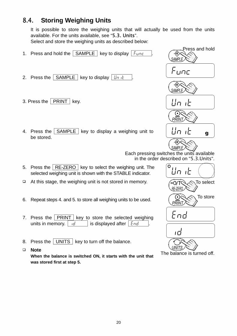
8.4. Storing Weighing Units It is possible to store the weighing units that will actually be used from the units
available. For the units available, see “5.3. Units”. Select and store the weighing units as described below:
1. Press and hold the SAMPLE key to display func . 2. Press the SAMPLE key to display Unit . 3. Press the PRINT key. 4. Press the SAMPLE key to display a weighing unit to
be stored. 5. Press the RE-ZERO key to select the weighing unit. The
selected weighing unit is shown with the STABLE indicator.
At this stage, the weighing unit is not stored in memory. 6. Repeat steps 4. and 5. to store all weighing units to be used. 7. Press the PRINT key to store the selected weighing
units in memory. id is displayed after end . 8. Press the UNITS key to turn off the balance.
Note When the balance is switched ON, it starts with the unit that
was stored first at step 5.
func
Unit
Unit
Press and hold
Unit
end
id
The balance is turned off.
Each pressing switches the units availablein the order described on "5.3.Units".
To select
To store

21
8.5. Function List
Class Item Param-eter Description
0 Auto power-off disabled poff Auto power-off 1 Auto power-off enabled
Automatically power off
0 Fast / sensitive 1 Cond
Response 2 Slow / stable
Software filtering
0 Judge precisely (± 0.5d)
1 (± 1d) 5t-b Stability band width
2 Judge moderately (± 2d)
The STABLE indicator is displayed when the fluctuationinterval of a regular time weighing display is less than the reference value.
0 Disabled trc Zero tracking 1 Enabled
Function to keep the display value at zero by tracking the zero point
0 Point (.) pnt Decimal point 1 Comma (,)
Decimal separator
0 Command and stream modes 1 Command and PRINT key
2 Command, PRINT key and auto-print A
3 Command, PRINT key and auto-print B
prt Data output mode
4 Command mode only
Auto-print A: + data Auto-print B: +/- data
0 No pause (general equipment) pU5e
Data output pause 1 1.6 seconds (for AD-8121)
Interval between continuous data
0 No output 1 AD-8121 format (*) info
GLP output 2 General format
GLP output format
0 2400 bps 1 4800 bps 2 9600 bps
bp5 Baud rate
3 1200 bps
0 7 bits, even parity 1 7 bits, odd parity btpr
Data and parity 2 8 bits, non parity
0 ACAI disabled aCai ACAI function 1 ACAI enabled
If “0” is set, no additional samples required.
0 1 d 1 1/10 d
Umin Minimum unit weight
2 total sample weight 5d (**)
d = digit : in unit of minimum display
0 10 pcs 1 25 pcs 2 50 pcs 3 100 pcs
func
5mpl Sample number
4 5 pcs
The number of samples shown first when entered into the unit weight storing mode
: Factory setting
22
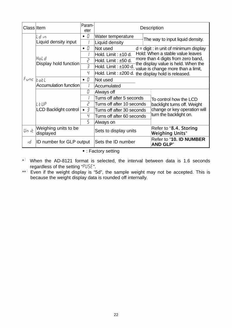
Class Item Param-eter Description
0 Water temperature ldin Liquid density input 1 Liquid density
The way to input liquid density.
0 Not used 1 Hold. Limit : ±10 d. 2 Hold. Limit : ±50 d. 3 Hold. Limit : ±100 d.
Hold Display hold function
4 Hold. Limit : ±200 d.
d = digit : in unit of minimum displayHold: When a stable value leaves more than 4 digits from zero band, the display value is held. When the value is change more than a limit, the display hold is released.
0 Not used totl Accumulation function 1 Accumulated
0 Always off 1 Turns off after 5 seconds 2 Turns off after 10 seconds 3 Turns off after 30 seconds 4 Turns off after 60 seconds
func
ltUp LCD Backlight control
5 Always on
To control how the LCD backlight turns off. Weight change or key operation will turn the backlight on.
Unit Weighing units to be displayed Sets to display units Refer to “8.4. Storing
Weighing Units”
id ID number for GLP output Sets the ID number Refer to “10. ID NUMBER AND GLP”
: Factory setting * : When the AD-8121 format is selected, the interval between data is 1.6 seconds
regardless of the setting “pU5e”. ** : Even if the weight display is “5d”, the sample weight may not be accepted. This is
because the weight display data is rounded off internally.
23
9. OPTIONS
The following options are available for the EJ-123/EJ-303 balance: EJ-02 USB interface EJ-03 RS-232C serial interface EJ-13 Density determination kit
Note The EJ-123/EJ-303 balance have only one option slot for a communications interface. Either the EJ-02 USB interface or the EJ-03 RS-232C serial interface can be installed at one time.
9.1. EJ-02 USB Interface The EJ-02 allows an EJ-123/EJ-303 balance to be connected with a printer or a
personal computer with the USB interface.
The EJ-02 can transmit the weight value (numerical value only) uni-directionally to a personal computer via USB.
The EJ-02 can transmit the weight value (numerical value only) directly to application software such as Microsoft Excel, Word, memo pad, and so on.
A special USB software driver is not necessary.
The EJ-02 cannot be used for bidirectional communication.
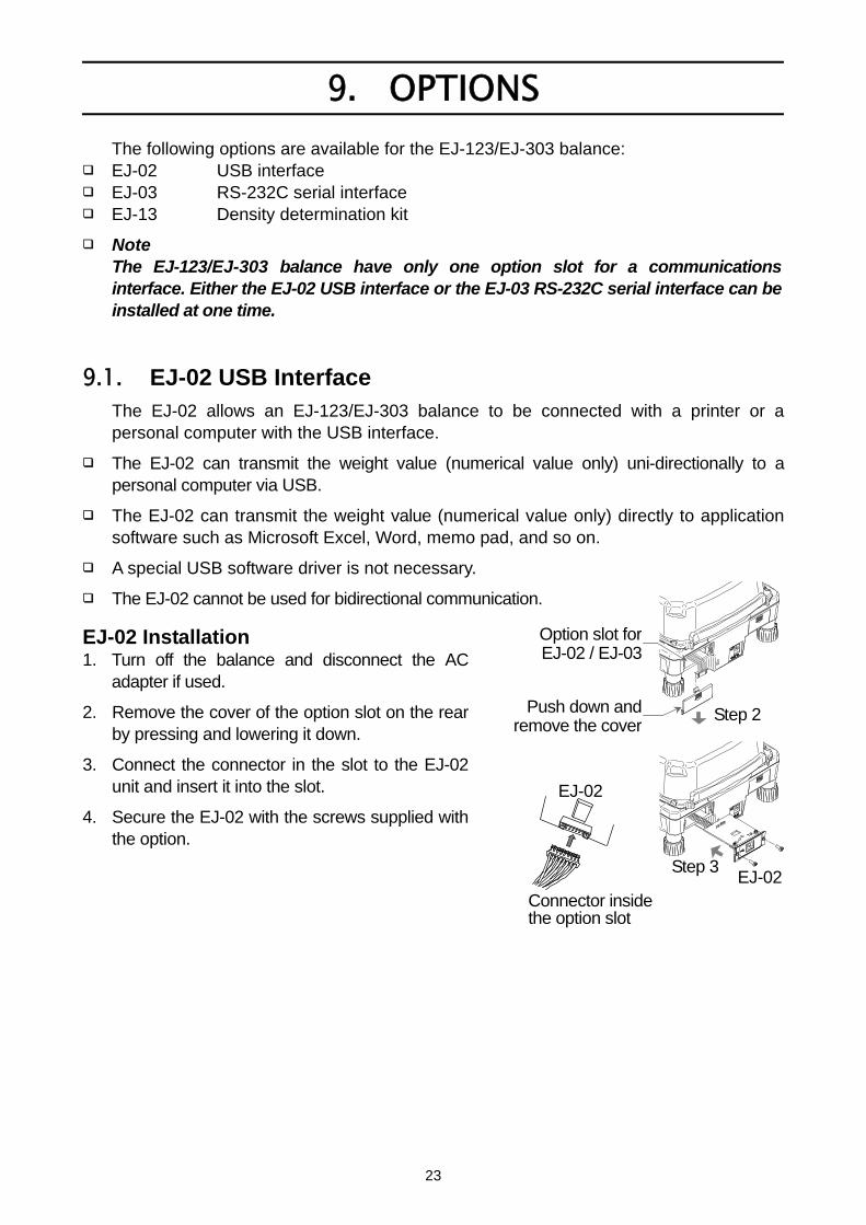
EJ-02 Installation 1. Turn off the balance and disconnect the AC
adapter if used.
2. Remove the cover of the option slot on the rear by pressing and lowering it down.
3. Connect the connector in the slot to the EJ-02 unit and insert it into the slot.
4. Secure the EJ-02 with the screws supplied with the option.
Push down and remove the cover
Step 2
Step 3EJ-02
EJ-02
Connector inside the option slot
Option slot forEJ-02 / EJ-03
24
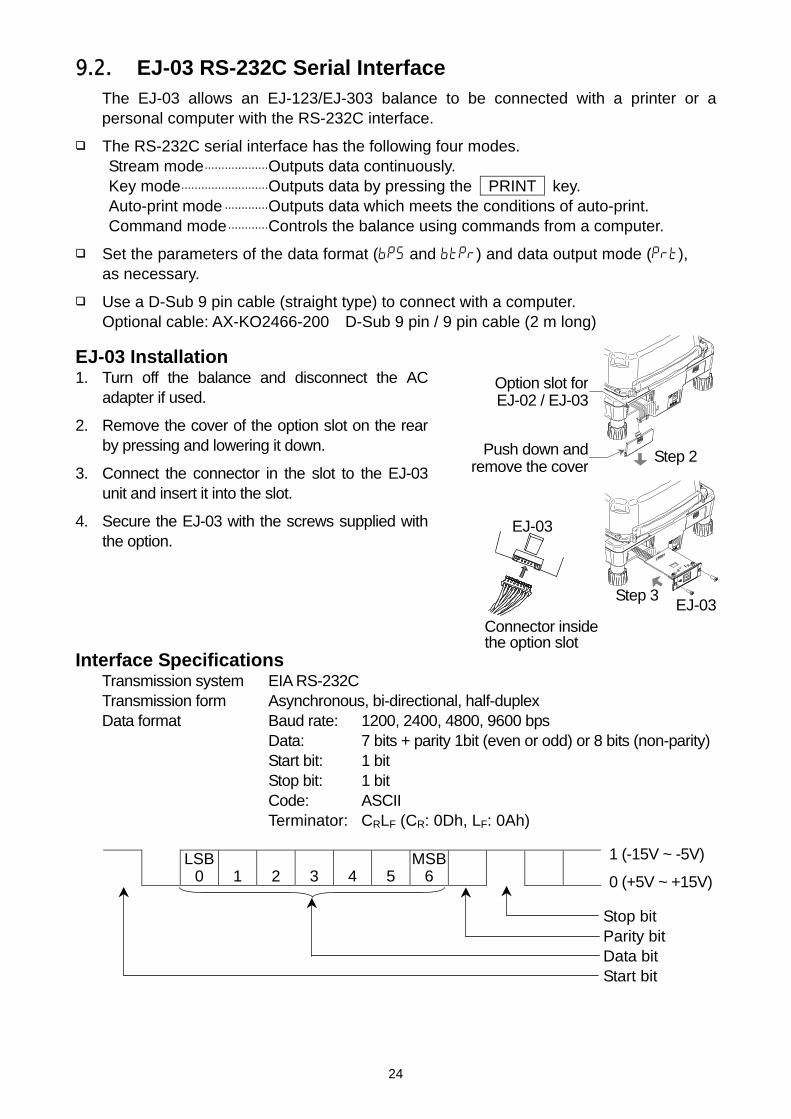
9.2. EJ-03 RS-232C Serial Interface The EJ-03 allows an EJ-123/EJ-303 balance to be connected with a printer or a
personal computer with the RS-232C interface.
The RS-232C serial interface has the following four modes. Stream mode...................Outputs data continuously. Key mode..........................Outputs data by pressing the PRINT key. Auto-print mode .............Outputs data which meets the conditions of auto-print. Command mode............Controls the balance using commands from a computer.
Set the parameters of the data format (bp5 and btpr) and data output mode (prt), as necessary.
Use a D-Sub 9 pin cable (straight type) to connect with a computer. Optional cable: AX-KO2466-200 D-Sub 9 pin / 9 pin cable (2 m long)
EJ-03 Installation 1. Turn off the balance and disconnect the AC
adapter if used.
2. Remove the cover of the option slot on the rear by pressing and lowering it down.
3. Connect the connector in the slot to the EJ-03 unit and insert it into the slot.
4. Secure the EJ-03 with the screws supplied with the option.
Interface Specifications
Transmission system EIA RS-232C Transmission form Asynchronous, bi-directional, half-duplex Data format Baud rate: 1200, 2400, 4800, 9600 bps Data: 7 bits + parity 1bit (even or odd) or 8 bits (non-parity) Start bit: 1 bit Stop bit: 1 bit Code: ASCII Terminator: CRLF (CR: 0Dh, LF: 0Ah)
LSB 0
1
2
3
4
5
MSB6
Stop bit Parity bit Data bit Start bit
1 (-15V ~ -5V)
0 (+5V ~ +15V)
Push down andremove the cover
Step 2
Step 3EJ-03
EJ-03
Connector inside the option slot
Option slot forEJ-02 / EJ-03
25
Separator (“ ” shows a space.)
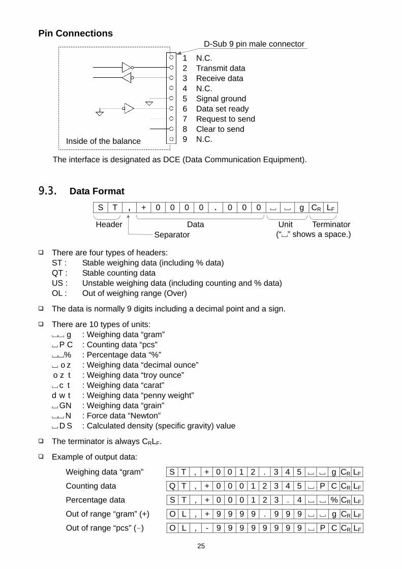
Pin Connections D-Sub 9 pin male connector
The interface is designated as DCE (Data Communication Equipment).
9.3. Data Format
S T , + 0 0 0 0 . 0 0 0 g CR LF
Header Data Unit Terminator
There are four types of headers: ST : Stable weighing data (including % data) QT : Stable counting data US : Unstable weighing data (including counting and % data) OL : Out of weighing range (Over)
The data is normally 9 digits including a decimal point and a sign.
There are 10 types of units: g : Weighing data “gram” P C : Counting data “pcs” % : Percentage data “%” o z : Weighing data “decimal ounce” o z t : Weighing data “troy ounce” c t : Weighing data “carat” d w t : Weighing data “penny weight” GN : Weighing data “grain” N : Force data “Newton” D S : Calculated density (specific gravity) value
The terminator is always CRLF.
Example of output data:
Weighing data “gram” S T , + 0 0 1 2 . 3 4 5 g CR LF
Counting data Q T , + 0 0 0 1 2 3 4 5 P C CR LF
Percentage data S T , + 0 0 0 1 2 3 . 4 % CR LF
Out of range “gram” (+) O L , + 9 9 9 9 . 9 9 9 g CR LF
Out of range “pcs” (-) O L , - 9 9 9 9 9 9 9 9 P C CR LF
1 N.C. 2 Transmit data 3 Receive data 4 N.C. 5 Signal ground 6 Data set ready 7 Request to send 8 Clear to send 9 N.C. Inside of the balance
26
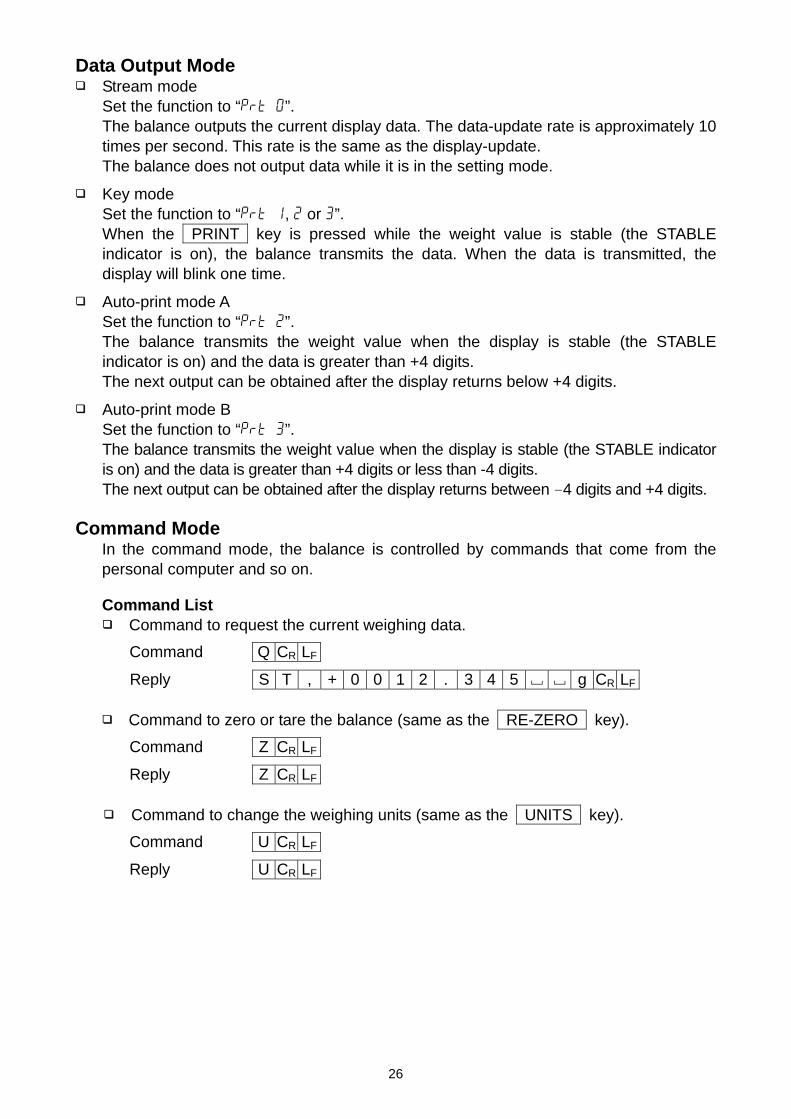
Data Output Mode Stream mode
Set the function to “prt 0”. The balance outputs the current display data. The data-update rate is approximately 10
times per second. This rate is the same as the display-update. The balance does not output data while it is in the setting mode.
Key mode Set the function to “prt 1, 2 or 3”. When the PRINT key is pressed while the weight value is stable (the STABLE
indicator is on), the balance transmits the data. When the data is transmitted, the display will blink one time.
Auto-print mode A Set the function to “prt 2”. The balance transmits the weight value when the display is stable (the STABLE
indicator is on) and the data is greater than +4 digits. The next output can be obtained after the display returns below +4 digits.
Auto-print mode B Set the function to “prt 3”. The balance transmits the weight value when the display is stable (the STABLE indicator
is on) and the data is greater than +4 digits or less than -4 digits. The next output can be obtained after the display returns between -4 digits and +4 digits. Command Mode
In the command mode, the balance is controlled by commands that come from the personal computer and so on.
Command List Command to request the current weighing data.
Command Q CR LF
Reply S T , + 0 0 1 2 . 3 4 5 g CR LF
Command to zero or tare the balance (same as the RE-ZERO key).
Command Z CR LF
Reply Z CR LF
Command to change the weighing units (same as the UNITS key).
Command U CR LF
Reply U CR LF
27
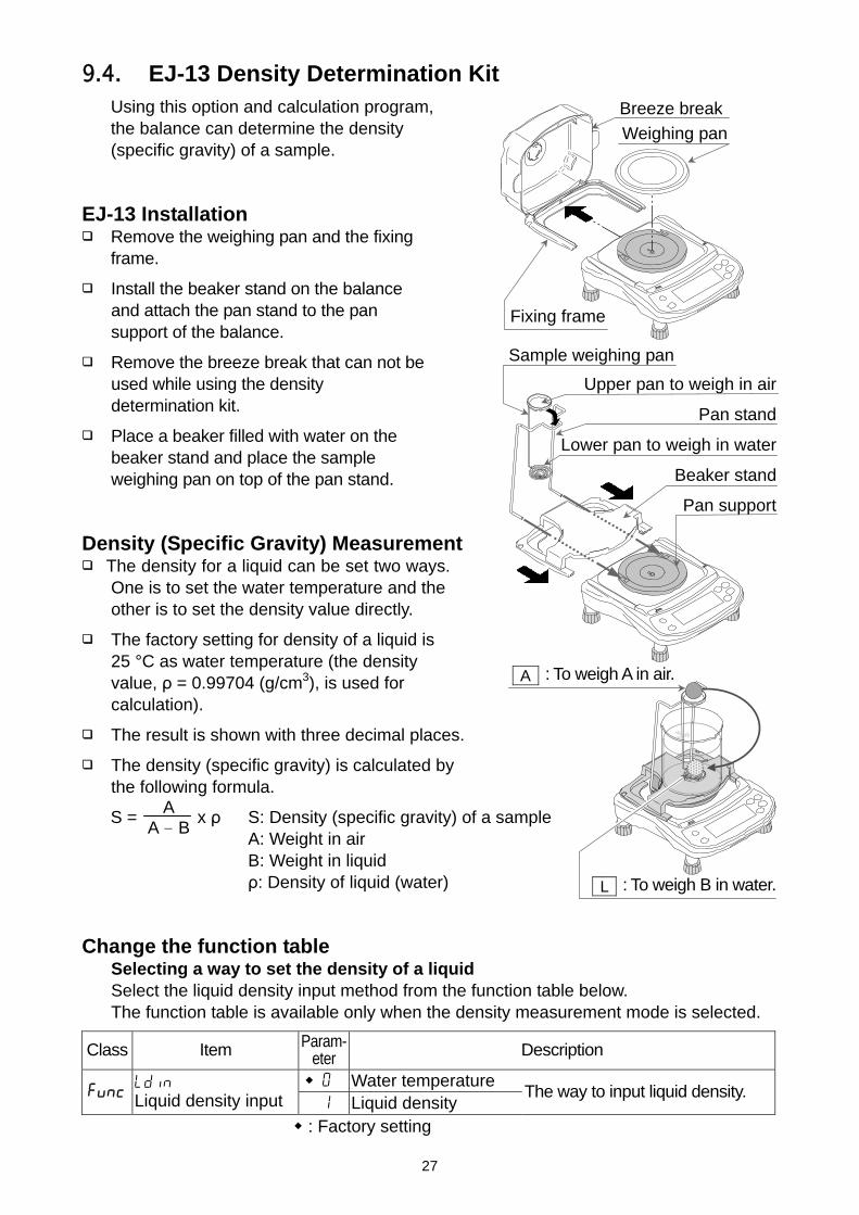
9.4. EJ-13 Density Determination Kit Using this option and calculation program, the balance can determine the density (specific gravity) of a sample.
EJ-13 Installation
Remove the weighing pan and the fixing frame.
Install the beaker stand on the balance and attach the pan stand to the pan support of the balance.
Remove the breeze break that can not be used while using the density determination kit.
Place a beaker filled with water on the beaker stand and place the sample weighing pan on top of the pan stand.
Density (Specific Gravity) Measurement
The density for a liquid can be set two ways. One is to set the water temperature and the other is to set the density value directly.
The factory setting for density of a liquid is 25 °C as water temperature (the density value, ρ = 0.99704 (g/cm3), is used for calculation).
The result is shown with three decimal places.
The density (specific gravity) is calculated by the following formula.
S = x ρ S: Density (specific gravity) of a sample A: Weight in air B: Weight in liquid ρ: Density of liquid (water)
Change the function table
Selecting a way to set the density of a liquid Select the liquid density input method from the function table below. The function table is available only when the density measurement mode is selected.
Class Item Param-eter Description
0 Water temperature func ldin Liquid density input 1 Liquid density
The way to input liquid density.
: Factory setting
A A - B
Upper pan to weigh in air
Pan stand
Lower pan to weigh in water
Beaker stand
Pan support
Sample weighing pan
Weighing pan
Fixing frame
L : To weigh B in water.
A : To weigh A in air.
Breeze break

28
Entering the density of a liquid (ldin = 0)
1. Press the UNITS key to select SG .
2. Press and hold the UNITS key to display the liquid density input mode. The display will show the water temperature currently set (factory setting: 25 °C).
3. Using the RE-ZERO (to increment the value) and SAMPLE keys (to shift the selected digit), set the value and press the PRINT key to store.
To cancel the setting procedure and return to the density measuring mode, press the UNITS key. The input value is not stored.
The relation between the water temperature and density is shown below.
°C +0 +1 +2 +3 +4 +5 +6 +7 +8 +9 0 0.99984 0.99990 0.99994 0.99996 0.99997 0.99996 0.99994 0.99990 0.99985 0.9997810 0.99970 0.99961 0.99949 0.99938 0.99924 0.99910 0.99894 0.99877 0.99860 0.9984120 0.99820 0.99799 0.99777 0.99754 0.99730 0.99704 0.99678 0.99651 0.99623 0.9959430 0.99565 0.99534 0.99503 0.99470 0.99437 0.99403 0.99368 0.99333 0.99297 0.9925940 0.99222 0.99183 0.99144 0.99104 0.99063 0.99021 0.98979 0.98936 0.98893 0.9884950 0.98804 0.98758 0.98712 0.98665 0.98618 0.98570 0.98521 0.98471 0.98422 0.9837160 0.98320 0.98268 0.98216 0.98163 0.98110 0.98055 0.98001 0.97946 0.97890 0.9783470 0.97777 0.97720 0.97662 0.97603 0.97544 0.97485 0.97425 0.97364 0.97303 0.9724280 0.97180 0.97117 0.97054 0.96991 0.96927 0.96862 0.96797 0.96731 0.96665 0.9660090 0.96532 0.96465 0.96397 0.96328 0.96259 0.96190 0.96120 0.96050 0.95979 0.95906
Entering the density of a liquid directly (ldin = 1)
1. Press the UNITS key to select SG .
2. Press and hold the UNITS key to display the liquid density input mode. The display will show the liquid density currently set (factory setting: 1.0000 g/cm3)
3. Using the RE-ZERO (to increment the value) and SAMPLE keys (to shift the selected digit), set the value and press the PRINT key to store.
To cancel the setting procedure and return to the density measuring mode, press the UNITS key. The input value is not stored.
d 1.0000 SG
t---25 SG
SG indicator
0.000 SG
A

29
Example of density measurement Selecting the density measurement mode
1. Press the UNITS key to select SG .
The weighing unit is “g”.
The display shows that A blinks and the balance is measuring the weight in air.
When the display does not show zero, press the RE-ZERO key to set the display to zero.
2. Place a sample on the upper pan. 3. Wait for the STABLE indicator to be displayed and
press the SAMPLE key to store the weight in air. 4. The display shows that L blinks and the balance
starts to measure the weight in water. 5. Place the sample on the lower pan in water.
Adjust the amount of water so that the sample is about 10 mm below the water surface.
6. Wait for the STABLE indicator to be displayed and
press the SAMPLE key. Then the balance reads the weight in water and shows the density (specific gravity) of the sample.
7. To continue the density measurement, press
the SAMPLE key again. To exit this measurement, press the UNITS key.
L : To weigh the sample in water.
A : To weigh the sample in air.
20.000 A
20.000 SGL
Measuring weight in water.
17.510 SGL
8.008 SG
SG indicator
0.000 SG
A
Measuring weight in air.
SG

30
10. ID NUMBER AND GLP
The ID number is used to identify the balance when Good Laboratory Practice (GLP) is used.
The ID number is stored in memory even if power to the balance is switched OFF.
The following GLP data is transmitted to a printer or a computer using the optional RS-232C serial interface.
The result of calibration (“Calibration report”) The result of calibration test (“Calibration test report”) The “Title block” and “End block” for GLP data
The GLP output format includes the balance manufacturer name, model number, serial number, ID number and space for a signature.
By using the AD-8121B, printing out dates and times is possible (GLP output format info = 1).
10.1. Setting The ID Number 1. Press and hold the SAMPLE key to display func . 2. Press the SAMPLE key several times to display id . 3. Press the PRINT key. Enter the ID number using the
following keys.
SAMPLE key.......... To select the digit blinking to be changed.
RE-ZERO key........ To set the character of the digit selected. See the table below for the “display character set”.
PRINT key ............... To store the value and proceed to the next step.
UNITS key ............... To cancel the value and proceed to the next step.
4. When the above operation has been completed, func appears after end .
5. Press the UNITS key to turn off the balance. Display Character Set
0 1 2 3 4 5 6 7 8 9 - A B C D E F G H I J K L M N O P Q R S T U V W X Y Z
0 1 2 3 4 5 6 7 8 9 - _ a b C d e f g H i j k l m n o p q r s t U v w x y z “ ” : Space
Press severaltimes
func
id
000000
end id
func
Set using the relevant keys
Press and hold
The balance is turned off.

31
10.2. GLP Report To print the GLP report, set the function to “info 1”, “pU5e 1” and set the
AD-8121B printer to MODE 3. To output the GLP report to a personal computer, set the function to “info 2”,
“pU5e 0” . Calibration Report
Perform calibration using a weight. Then the balance will output a calibration report. Refer to “7.1. Calibration Using A Weight” about the calibration.
1. Perform calibration according to “7.1. Calibration Using A Weight”.
2. end appears when the calibration has been completed.
3. glp is displayed and calibration report is output.
4. end is displayed again. Remove the weight. The balance is turned off.
AD-8121 format “info 1” General format “info 2” ~ : Space, ASCII 20h CR : Carriage return, ASCII 0Dh LF : Line feed, ASCII 04Ah
end
glp
Operation of Calibration(See “7.CALIBRATION”)
end
GLP output
The balance is turned off.
___________A_&_D
MODEL_____EJ-123
S/N____Q12345678 ID________ABCDEF
DATE__2013/11/14
TIME____02:53:21 CALIBRATED(EXT.)
CAL.WEIGHT
_____+100.000__g SIGNATURE
-_-_-_-_-_-_-_-_
~~~~~~~~~~~A~&~D<CRLF> MODEL~~~~~EJ-123<CRLF> S/N~~~~Q12345678<CRLF> ID~~~~~~~~ABCDEF<CRLF> DATE<CRLF> <CRLF> TIME<CRLF> <CRLF> CALIBRATED(EXT.)<CRLF> CAL.WEIGHT<CRLF> ~~~~~+100.000~~g<CRLF> SIGNATURE<CRLF> <CRLF> <CRLF> ----------------<CRLF> <CRLF> <CRLF>
Manufacturer Model
Serial number ID number
Date Time
Calibration type
Calibration weight Signature
32
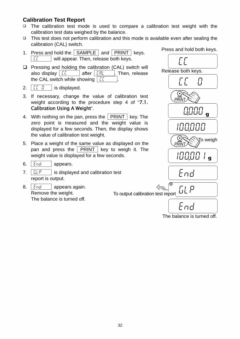
Calibration Test Report The calibration test mode is used to compare a calibration test weight with the
calibration test data weighed by the balance. This test does not perform calibration and this mode is available even after sealing the
calibration (CAL) switch.
1. Press and hold the SAMPLE and PRINT keys. CC will appear. Then, release both keys.
Pressing and holding the calibration (CAL) switch will also display CC after Cal . Then, release the CAL switch while showing CC .
2. CC 0 is displayed.
3. If necessary, change the value of calibration test weight according to the procedure step 4 of “7.1. Calibration Using A Weight”.
4. With nothing on the pan, press the PRINT key. The zero point is measured and the weight value is displayed for a few seconds. Then, the display shows the value of calibration test weight.
5. Place a weight of the same value as displayed on the pan and press the PRINT key to weigh it. The weight value is displayed for a few seconds.
6. end appears.
7. glp is displayed and calibration test report is output.
8. end appears again. Remove the weight. The balance is turned off.
The balance is turned off.
CC
CC 0
Press and hold both keys.
Release both keys.
0.000
100.000
100.001
To weigh
end
glp
end
To output calibration test report

33
AD-8121 format “info 1” General format “info 2” ~ : Space, ASCII 20h CR : Carriage return, ASCII 0Dh LF : Line feed, ASCII 04Ah Output Of “Title Block” And “End Block”
When a weight value is recorded as the GLP report. “Title block” and “End block” are added at the beginning and at the end of a group of weight values.
“Title Block”
1. Press and hold the PRINT key. Release the PRINT key when 5tart is displayed. The balance outputs the “Title block”.
2. The balance can output the weight value by pressing the PRINT key or selecting the auto-print mode.
___________A_&_D
MODEL_____EJ-123 S/N____Q12345678
ID________ABCDEF
DATE__2013/11/14 TIME____02:53:21
CAL.TEST(EXT.)
ACTUAL ________0.000__g
_____+100.001__g
TARGET _____+100.000__g
SIGNATURE
-_-_-_-_-_-_-_-_
~~~~~~~~~~~A~&~D<CRLF> MODEL~~~~~EJ-123<CRLF> S/N~~~~Q12345678<CRLF> ID~~~~~~~~ABCDEF<CRLF> DATE<CRLF> <CRLF> TIME<CRLF> <CRLF> CAL.TEST(EXT.)<CRLF> ACTUAL<CRLF> ~~~~~~~~0.000~~g<CRLF> ~~~~~+100.001~~g<CRLF> TARGET<CRLF> ~~~~~+100.000~~g<CRLF> SIGNATURE<CRLF> <CRLF> <CRLF> ----------------<CRLF> <CRLF> <CRLF>
• • • •
5tart
0.000
To output “Title block”
12.345
23.456
To output weight value
Press and hold
end
Manufacturer Model
Serial number ID number
Date Time
Calibration test type
Zero value Target weight value
Target weight
Signature

34
“End Block” 3. Press and hold the PRINT key.
Release the PRINT key when recend is displayed. The balance outputs the “End block”.
4. end is displayed. The balance return to the weighing mode.
AD-8121 format “info 1” General format “info 2” ~ : Space, ASCII 20h CR : Carriage return, ASCII 0Dh LF : Line feed, ASCII 04Ah
recend To output “End block”
Press and hold
The balance return to the weighing mode.
end
___________A_&_D
MODEL_____EJ-123
S/N____Q12345678 ID_______ABCDEF
DATE__2013/11/14
START TIME____02:53:21
ST,+0012.345__g ST,+0023.456__g
ST,+0034.567__g
ST,+0045.678__g
END
TIME____02:55:21 SIGNATURE
-_-_-_-_-_-_-_-_
~~~~~~~~~~~A~&~D<CRLF> MODEL~~~~~EJ-123<CRLF> S/N~~~~Q12345678<CRLF> ID~~~~~~~~ABCDEF<CRLF> DATE<CRLF> <CRLF> START<CRLF> TIME<CRLF> <CRLF> <CRLF> ST,+0012.345~~g<CRLF> ST,+0023.456~~g<CRLF> ST,+0034.567~~g<CRLF> ST,+0045.678~~g<CRLF> <CRLF> END<CRLF> TIME<CRLF> <CRLF> SIGNATURE<CRLF> <CRLF> <CRLF> ----------------<CRLF> <CRLF> <CRLF>
Title block
Manufacturer Model
Serial number ID number
Date Start time
Weight value
End time Signature
End block
35
11. MAINTENANCE
11.1. Notes On Maintenance Do not disassemble the balance. Contact your local A&D dealer if your balance needs
service or repair.
Please use the original package for transportation.
Do not use organic solvents to clean the balance. Use a lint free cloth dampened with warm water and a mild detergent.
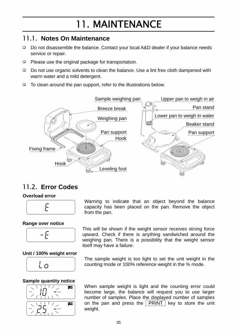
To clean around the pan support, refer to the illustrations below.
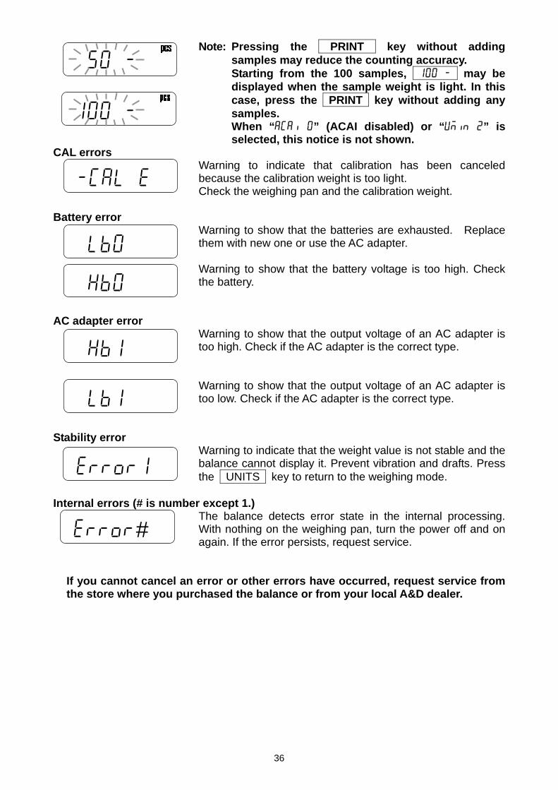
11.2. Error Codes Overload error
Warning to indicate that an object beyond the balance capacity has been placed on the pan. Remove the object from the pan.
Range over notice
This will be shown if the weight sensor receives strong force upward. Check if there is anything sandwiched around the weighing pan. There is a possibility that the weight sensor itself may have a failure.
Unit / 100% weight error The sample weight is too light to set the unit weight in the counting mode or 100% reference weight in the % mode.
Sample quantity notice
When sample weight is light and the counting error could become large, the balance will request you to use larger number of samples. Place the displayed number of samples on the pan and press the PRINT key to store the unit weight.
eeeeee
lo
25 -
10 -
--e
Upper pan to weigh in air
Pan stand
Lower pan to weigh in water
Beaker stand
Pan support
Sample weighing pan
Hook
Weighing pan
Fixing frame
Hook
Breeze break
Leveling foot
Pan support
36
Note: Pressing the PRINT key without adding samples may reduce the counting accuracy.
Starting from the 100 samples, 100 - may be displayed when the sample weight is light. In this case, press the PRINT key without adding any samples.
When “aCai 0” (ACAI disabled) or “Umin 2” is selected, this notice is not shown.
CAL errors Warning to indicate that calibration has been canceled because the calibration weight is too light. Check the weighing pan and the calibration weight.
Battery error
Warning to show that the batteries are exhausted. Replace them with new one or use the AC adapter.
Warning to show that the battery voltage is too high. Check the battery.
AC adapter error
Warning to show that the output voltage of an AC adapter is too high. Check if the AC adapter is the correct type.
Warning to show that the output voltage of an AC adapter is too low. Check if the AC adapter is the correct type.
Stability error
Warning to indicate that the weight value is not stable and the balance cannot display it. Prevent vibration and drafts. Press the UNITS key to return to the weighing mode.
Internal errors (# is number except 1.)
The balance detects error state in the internal processing. With nothing on the weighing pan, turn the power off and on again. If the error persists, request service.
If you cannot cancel an error or other errors have occurred, request service from the store where you purchased the balance or from your local A&D dealer.
-Cal e
lb0
error1
100 -
50 -
Hb1
lb1
Hb0
error#
37
12. SPECIFICATIONS 12.1. Generals
MODEL EJ-123 EJ-303
Weight capacity 120 g 310 g
Minimum display “d” = digit 0.001 g 0.001 g
Repeatability (Standard deviation) 0.003 g 0.003 g
Linearity ±0.003 g ±0.003 g
Sensitivity drift ±20 ppm / °C (10 °C to 30 °C / 50 °F to 86 °F)
No. of samples 5, 10, 25, 50 or 100 pieces
Max. count * 120,000 pcs 310,000 pcs
Min. unit weight * 0.001 g
Min. % display 0.01 %
Min. 100 % weight 0.1 g
Display 7 segment LCD display with backlight (Character height 16 mm)
Display update 10 time per second
Operating temp. 10 °C to 30 °C / 50 °F to 86 °F, less than 85 %R.H. (non-condensing)
Power supply AC adapter or 4 x “AA” size dry-cell batteries
Battery operation Approximately 80 hours (backlight off, alkaline batteries)
Weighing pan size 110 mm ø
Weight Approximately 1160 g
Calibration weight (factory setting) 100 g 300 g
* : In case of “Umin 0” (factory setting)
12.2. Weighing Units
MODEL EJ-123 EJ-303
Capacity 4.2329 oz 10.9349 oz oz
Min. display 0.0001 oz 0.0001 oz
Capacity 3.8581 ozt 9.9667 ozt ozt
Min. display 0.0001 ozt 0.0001 ozt
Capacity 600.000 ct 1550.000 ct ct
Min. display 0.005 ct 0.005 ct
Capacity 77.162 dwt 199.335 dwt dwt
Min. display 0.001 dwt 0.001 dwt
Capacity 1851.88 GN 4784.04 GN GN
Min. display 0.02 GN 0.02 GN
38
12.3. Options EJ-02 USB interface EJ-03 RS-232C serial interface EJ-13 Density determination kit
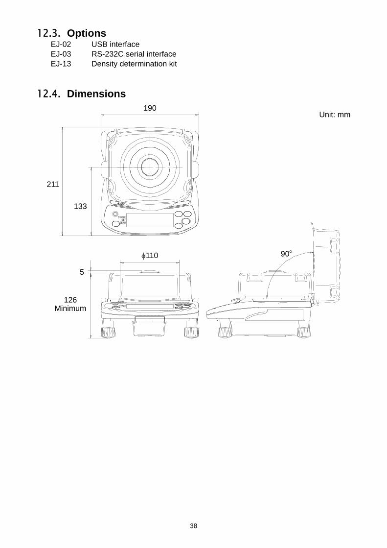
12.4. Dimensions
Unit: mm
190
110
133
211
5
126 Minimum
90○

39
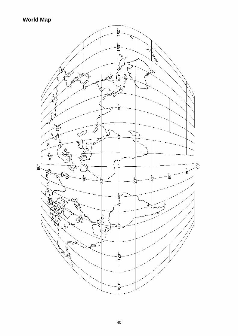
13. GRAVITY ACCELERATION MAP Values Of Gravity At Various Locations
Amsterdam 9.813 m/s2 Manila 9.784 m/s2
Athens 9.807 m/s2 Melbourne 9.800 m/s2
Auckland NZ 9.799 m/s2 Mexico City 9.779 m/s2
Bangkok 9.783 m/s2 Milan 9.806 m/s2
Birmingham 9.813 m/s2 New York 9.802 m/s2
Brussels 9.811 m/s2 Oslo 9.819 m/s2
Buenos Aires 9.797 m/s2 Ottawa 9.806 m/s2
Calcutta 9.788 m/s2 Paris 9.809 m/s2
Cape Town 9.796 m/s2 Rio de Janeiro 9.788 m/s2
Chicago 9.803 m/s2 Rome 9.803 m/s2
Copenhagen 9.815 m/s2 San Francisco 9.800 m/s2
Cyprus 9.797 m/s2 Singapore 9.781 m/s2
Djakarta 9.781 m/s2 Stockholm 9.818 m/s2
Frankfurt 9.810 m/s2 Sydney 9.797 m/s2
Glasgow 9.816 m/s2 Taichung 9.789 m/s2
Havana 9.788 m/s2 Tainan 9.788 m/s2
Helsinki 9.819 m/s2 Taipei 9.790 m/s2
Kuwait 9.793 m/s2 Tokyo 9.798 m/s2
Lisbon 9.801 m/s2 Vancouver, BC 9.809 m/s2
London (Greenwich) 9.812 m/s2 Washington DC 9.801 m/s2
Los Angeles 9.796 m/s2 Wellington NZ 9.803 m/s2
Madrid 9.800 m/s2 Zurich 9.807 m/s2
40
World Map


3-23-14 Higashi-Ikebukuro, Toshima-ku, Tokyo 170-0013, JAPAN Telephone: [81] (3) 5391-6132 Fax: [81] (3) 5391-6148 A&D ENGINEERING, INC. 1756 Automation Parkway, San Jose, California 95131, U.S.A. Telephone: [1] (408) 263-5333 Fax: [1] (408)263-0119 A&D INSTRUMENTS LIMITED Unit 24/26 Blacklands Way, Abingdon Business Park, Abingdon, Oxfordshire OX14 1DY United KingdomTelephone: [44] (1235) 550420 Fax: [44] (1235) 550485 A&D AUSTRALASIA PTY LTD 32 Dew Street, Thebarton, South Australia 5031, AUSTRALIA Telephone: [61] (8) 8301-8100 Fax: [61] (8) 8352-7409 A&D KOREA Limited 한국에이.엔.디(주) 서울특별시 영등포구 국제금융로6길33 (여의도동) 맨하탄빌딩 817 우편 번호 150-749 ( 817, Manhattan Bldg., 33. Gukjegeumyung-ro 6-gil, Yeongdeungpo-gu, Seoul, 150-749 Korea ) 전화: [82] (2) 780-4101 팩스: [82] (2) 782-4280 OOO A&D RUS OOO "ЭЙ энд ДИ РУС" 121357, Российская Федерация, г.Москва, ул. Верейская, дом 17 ( Business-Center "Vereyskaya Plaza-2" 121357, Russian Federation, Moscow, Vereyskaya Street 17 ) тел.: [7] (495) 937-33-44 факс: [7] (495) 937-55-66 A&D INSTRUMENTS INDIA PRIVATE LIMITED
( 509, Udyog Vihar, Phase- , Gurgaon - 122 016, Haryana, India )
: 91-124-4715555 : 91-124-4715599