1xev-do airlink overview
TRANSCRIPT

1xEV: 1x EVolution
IS-856 TIA/EIA Standard
Airlink Overview
QUALCOMM, Inc. November 7, 2001
Revision 7.2

Table Of Contents 1.0 INTRODUCTION...................................................................................................................................... 3
2.0 1XEV AIRLINK DESIGN ....................................................................................................................... 4 2.1 AVERAGE DATA THROUGHPUT............................................................................................................. 5 2.2 TURBO CODES......................................................................................................................................... 5 2.3 1XEV FORWARD LINK............................................................................................................................ 6
2.3.1 Shared Forward Link Channel.......................................................................................................... 6 2.3.2 Forward Link Channel Structure ...................................................................................................... 8 2.3.2.1 Burst Pilot ...................................................................................................................................... 9 2.3.3 Forward Link Adaptive Modulation ............................................................................................... 10
2.4 FIELD TESTING...................................................................................................................................... 12 2.5 SCHEDULING ALGORITHM .................................................................................................................. 12
2.5.1 Proportional Fairness Scheduling .................................................................................................. 13 2.6 1XEV REVERSE LINK ............................................................................................................................ 16
2.6.1 Reverse Link Channel Structure...................................................................................................... 17 2.6.2 Reverse Link Modulation ................................................................................................................ 18
2.7 1XEV SIGNALING ................................................................................................................................. 18 2.7.1 Physical Layer ................................................................................................................................. 19 2.7.2 MAC Layer ..................................................................................................................................... 19 2.7.3 Security Layer ................................................................................................................................. 20 2.7.4 Connection Layer ............................................................................................................................ 21 2.7.5 Session Layer................................................................................................................................... 22 2.7.6 Stream Layer ................................................................................................................................... 23 2.7.7 Application Layer............................................................................................................................ 23
3.0 POINT-TO-POINT PROTOCOL .......................................................................................................... 24
4.0 1XEV HANDOFFS .................................................................................................................................. 25 4.1 Handoffs to IS-95/1x Systems............................................................................................................ 25
5.0 SUMMARY.............................................................................................................................................. 26
2

1.0 Introduction
1xEV technology (also known as, High Data Rate “HDR”) is a high performance and cost effective Internet solution for consumers and business professionals. It offers high speed, high capacity wireless Internet technology, which is compatible with CDMA networks and optimized for packet data services. 1xEV offers a combination of high performance and economic benefits which is unprecedented in systems capable of portable, mobile, and fixed services. 1xEV achieves this performance with minimal network and spectrum resources, providing a highly spectrally efficient technology.
The 1xEV working group was established in 3GPP2, TSG-C in March 2000. The 1xEV name, which stands for ‘Evolution’ was coined in the standards process. The standard was balloted and adopted by 3GPP2, as C.S0024, and by TIA/EIA, as IS-856, in October 2000. The recommended capabilities of the cdma2000 standard includes two interoperable modes: an integrated 1x mode optimized for voice and medium data speeds, and a 1xEV mode optimized for high capacity/high speed data and Internet access. The following are just some of the infrastructure manufacturers who have publicly announced support for 1xEV along with 1x: Lucent, Hitachi, LGIC, Samsung, Nortel, Ericsson, Airvana, ComDev and Motorola. This will further ensure that the evolution path from cdmaOne through cdma2000 will effectively provide the maximum capability in the most reasonable timetable.
The phenomenal growth of Information Technology and the Internet, and the general population’s desire for timely information services, create a need for a high performance wireless Internet technology. Trends such as PC-on-a-Chip, wireless-capable Personal Digital Assistants, Smart Phones and Auto PCs point to the availability of a large number of new data-capable devices, enabling each of us to communicate wirelessly anytime, anywhere. 1xEV is the ideal technology for providing such wireless Internet services, and is founded on a proven wireless technology and a sound economic basis. 1xEV is built on mainstream IP backbones using off-the-shelf IP network elements without any modifications.
1xEV systems are designed to be highly interoperable with CDMA systems. Leveraging from the same RF characteristics as IS-95/1x CDMA, dual-mode IS-95/1x and 1xEV Access Terminals can be offered in a compact and cost-effective manner. Within a given network, dual-mode IS-95/1x and 1xEV devices allow users to access voice services via the IS-95/1x frequency carrier, while receiving data services through the 1xEV frequency carrier. Wireless subscribers will benefit
3

from IS-95/1x’s excellent voice quality, as well as 1xEV’s high performance data services and mobile flexibility.
2.0 1xEV Airlink Design
The 1xEV airlink is designed for packet data optimization. It is spectrally efficient and provides 7.4 Mbps/cell (3 sectors) aggregate forward peak throughput with a single CDMA frequency carrier (1.25 MHz).
One of the key premises of 1xEV is that voice and data have very different requirements and there will be inefficiencies anytime the two services are combined. With that in mind, the 1xEV design requires a separate CDMA carrier. It is however important to note that the 1xEV waveform retains 100% compatibility with IS-95/1x from the RF standpoint. The 1xEV waveform uses the same 1.228Mcps chip rate, link budgets, network plans, and RF designs on both Access Terminals and infrastructure. Furthermore, optimizing voice and data on different carriers is advantageous for both services: it simplifies system software development and avoids difficult load-balancing tasks.
1x/1xEV systems proven technologies are the lowest risk alternative. 1xEV systems are currently being field trialed in various parts of the world. 1xEV over-the-air system, available since September 1998, demonstrated features and data rates that are proven from real field data experience.
1xEV’s forward link uses power efficiently. The access terminal continually updates the Access Network with the data rate it can receive. With this information the system can service a single user at any instant. This rate control feature enables the 1xEV Access Point to always transmit at full power achieving very high peak rates for users that are in good coverage area.
The Access Terminal and the Access Point jointly determine each user’s forward link data. The Access Terminal measures the pilot strength, and continuously requests an appropriate data rate based on the channel conditions. The Access Point encodes the forward link at exactly the highest rate that the subscriber’s wireless channel can support at any instant.
4

2.1 Average Data Throughput
The majority of data applications receive larger amounts of data from the wireless network’s infrastructure, than they transmit in the reverse direction. Therefore, 1xEV provides asymmetric data rates on the forward and reverse links.
1xEV’s peak data rate is:
Forward link = 2.457 Mbps/sector
Reverse link = 153.6 kbps/sector
1xEV airlink uses the network resources very efficiently by providing high performance average data throughput with only 1.25 MHz of spectrum. Given a loaded 1xEV sector, with a number of users distributed uniformly across the coverage area, the average forward link throughput in a 3-sector cell is:
Forward link: Pedestrian Environment = 3.1 Mbps/cell (Single Receive Antenna) = 4.0 Mbps/cell (Dual Receive Antenna) Low Speed
Mobile Environment = 1.3 Mbps/cell (Single Receive Antenna) = 2.5 Mbps/cell (Dual Receive Antenna)
High Speed Mobile Environment = 2.0 Mbps/cell (Single Receive Antenna)
= 3.1 Mbps/cell (Dual Receive Antenna)
Reverse link = 600 kbps/cell
The above throughput numbers do not assume transmit diversity at the cell site.
Access Terminals with dual receive antennas and receive diversity reception have the benefit of more accurately decoding the received information. Overall, this decreases retransmissions and improves system efficiency.
2.2 Turbo Codes
1xEV takes advantage of parallel codes and turbo decoding techniques. Hence, frame sizes utilized are larger than IS-95/1x frames. Code rates (R= 1/4 and 1/2) are used on the reverse channels, and code rates (R= 1/5 and 1/3) are used on the forward channels.
5

Data Pilot
1xEV
Reverse Forward
ACK DataMediumAccessControl
Pilot Reverse Power Control
Reverse Activity
Data Rate
Control
ReverseRate
Indicator
AccessTrafficControlTraffic Medium Access Control
Pilot
Diagram 1 – 1xEV Channel Structure
2.3 1xEV Forward Link
2.3.1 Shared Forward Link Channel
The 1xEV design employs a shared forward link and can serve a user at any instant. When being served, an Access Terminal receives the full power of the cell transmitter (Diagram 2). The Access Terminal calculates its C/I and tells the Access Point the highest data rate it can receive information. This allows the Access Point transmitter to operate at full power and transmit data at the highest data rate each Access Terminal requests.
There are additional benefits of a shared forward link. The scheduling algorithm takes advantage of multiple users and optimizes the data transmission on the forward link. As more subscribers access the 1xEV system, the scheduler assists in improving the traffic flow by fairly scheduling data to each subscriber (see section 2.5). The improved efficiency actually increases the subscriber’s average throughput.
6

SectorTransmit
SectorTransmit
ArNei
1stterct
Tbupua
Abgw
IS-95 Forward Link StructureIS-95 Forward Link Structure 1xEV Forward Link Structure1xEV Forward Link Structure
Power
Time
PTX (max)
Paging ChannelPaging ChannelSync ChannelSync Channel
Total TrafficTotal Traffic
Unused Margin
Pilot ChannelPilot Channel
Pilo
t Cha
nnel
Con
trol
Cha
nnel
Total Data
Pilo
t Cha
nnel
Con
trol
Cha
nnel
Total Data
PowerPTX (max)
Time
Diagram 2 – 1xEV maximizes data throughput via efficient use of the AP output power
maximum of 60 simultaneous users in the “connected” state, i.e. actively equesting and receiving packets, can be served by a 1xEV sector at any given time. ote that this number represent active connected users (not in dormant state). For
xample, if the users in a sector are using applications with 10% activity factor, then n effect 600 users in a sector can be served during the busy hour.
xEV supports both high speed and high capacity applications. In the case of high-peed applications, having tens of active users per sector, at any given time, ensures he users achieve high throughputs. In the case of low data rate applications, where he users are receiving small amounts of information (e.g., stock quotes, telemetry, tc.), the users will not use the channel for a long period of time. The users will eceive their short burst of information and will then release the Forward Link hannel. In this case, a much larger number of users (in order of 100's of users) can ake turns being one of the 60 active users at a given instant.
he 60 active users in a sector are power controlled by the reverse power control its (RPC). Each power controlled access terminal is assigned a Walsh cover that is sed to cover each user’s forward link packets. W64 are being used and hence 64 ossible Walsh covers are available to be assigned to users. 4 out of these 64 are sed for other purposes, which leaves 60 reverse power control bits that can ctually be assigned to users.
larger number of users are served by the system at any given time, leveraging the ursty nature of the traffic. When a user is not actively using the link, his airlink oes dormant. When he starts using it again, the airlink will automatically come up ithout any special intervention on the part of the user.
7

2.3.2 Forward Link Channel Structure
Diagram 4 –1xEV
11
UserN
UserN
248 Slots
Forward Link TrafficControlChannel
ControlChannel
426.67 ms13.33 ms
TrafficTraffic
8 Slots
/2 Slot 1/2 Slot1.67 ms
The time each user receives data on the forward traffic channel
varies for each data rate
Active Users
13.33 ms
UserN
UserN
248 Slots
Forward Link TrafficControlChannel
ControlChannel
426.67 ms13.33 ms
TrafficTraffic
8 Slots
/2 Slot 1/2 Slot1.67 ms
The time each user receives data on the forward traffic channel
varies for each data rate
Active Users
13.33 ms
Diagram 3 – 1xEV Forward Channel Structure
The 1xEV forward link is structured to maximize the overall data throughput of a given sector. Hence, the Access Points are always transmitting at full power serving one user at a time. There are no predetermined time slots; the time the user is on the forward traffic channel depends on the channel condition (C/I).
The 1xEV Forward Channel consists of the following time-multiplexed channels: the Pilot Channel, the Forward Medium Access Control (MAC) Channel, and the Forward Traffic Channel or the Control Channel. The Traffic Channel carries user data packets. The Control Channel carries control messages, and it may also carry user traffic.
The forward link is defined in terms of frames of length 26.67 ms, aligned to the PN rolls of the zero offset PN sequences. Within a frame, there are 16 slots, each of length of 2048 chips or 1.67 ms duration. Each frame is composed of two half-frame units of 8 slots. Each slot is further divided into two half-slots, each of which contains a pilot burst. Each pilot burst has a duration of 96 chips, and is centered at the midpoint of the half slot. Within each slot, the Pilot, MAC and Traffic or Control Channels are time multiplexed (TM). All time-division multiplexed channels are transmitted at the maximum power of the sector. Note that no
8

predetermined time slots are allocated to users. Frames, slots, etc are used as units of time.
The MAC Channel consists of two subchannels: the Reverse Power Control (RPC) Channel and the Reverse Activity (RA) Channel. The RA Channel transmits a reverse link activity bit (RAB) stream.
The Control Channel is transmitted at a data rate of 38.4 kbps or 76.8 kbps. The modulation characteristics for the Control Channel transmitted at 38.4 kbps are the same as those of the Forward Traffic Channel transmitted at 38.4 kbps. The modulation characteristics for the Control Channel transmitted at 76.8 kbps are the same as those of the Control Channel transmitted at 38.4 kbps except that the packet is transmitted in eight slots.
2.3.2.1 Burst Pilot
1xEV uses a burst pilot, which is optimal for bursty packet data services. The burst pilot is not transmitted on a separate code channel as in IS-95/1x, but is punctured into the forward link waveform at pre-determined intervals. The 1xEV burst pilot is transmitted at the maximum power that the cell is enabled to transmit. Using the full power of the cell for the pilot provides the highest possible pilot Signal-to-Noise Ratio (SNR) so that an accurate estimate can be obtained quickly, even during dynamic channel conditions.
Time
Power
Slot 2 Slot 3
Time
Power
Slot 1 Slot 2
Slot 1
Max Power
Max Power
Pilot Bursts
User Data
Diagram 4 – 1xEV Forward Link Burst Pilot
The burst pilot is received only in the presence of pilots from other Access Points and is not affected by other transmissions of data. Since the pilot is transmitted at the full power of the Access Point, the Access Terminal recognizes the burst as strictly the pilot signal. The Access Terminal does not need to subtract the effect of
9

data transmissions that may be occurring at the same time as the pilot. This results in a high Signal-to-Noise ratio for the pilot signal, which aids in rapid C/I estimation.
2.3.3 Forward Link Adaptive Modulation
The 1xEV forward link offers a range of different data rates. The data rates match the range of channel conditions experienced in a typical cellular/PCS networks.
QPSK modulation is used to achieve 38.4 kbps through 1,228.8 kbps data rates (with the exception of 921.6 kbps), 8-PSK for 921.6 kbps and 1,843.2 kbps, and 16-QAM for 1,228.8 kbps and 2,457.6 kbps.
Table 1: 1xEV Forward Link
Data Rates (kbps)
Modulation Type
Bits perEncoder Packet
Code Rate
Encoder PacketDuration (ms)
Number of Slots
38.4 76.8 153.6 307.2 307.2 614.4 614.4 921.6 1228.8 1228.8 1843.2 2457.6
QPSK QPSK QPSK QPSK QPSK QPSK QPSK 8 PSK QPSK 16QAM 8 PSK 16QAM
1024 1024 1024 1024 2048 1024 2048 3072 2048 4096 3072 4096
1/5 1/5 1/5 1/5 1/3 1/3 1/3 1/3 1/3 1/3 1/3 1/3
26.67 13.33 6 .67 3.33 6.67 1.67 3.33 3.33 1.67 3.33 1.67 1.67
16 8 4 2 4 1 2 2 1 2 1 1
Physical Layer Parameters
The 1xEV forward link supports dynamic data rates. The Access Terminal constantly measures the channel C/I, then requests the appropriate data rate for the channel conditions every 1.67 ms. The Access Point receives the Access Terminal’s request for a particular data rate, and encodes the forward link data at exactly the highest rate that the wireless channel can support at the requested instant. Just enough margin is included to allow the Access Terminal to decode the data with a low erasure rate. In this manner, as the subscriber’s application needs and channel conditions vary, the optimum data rate is determined and served to the user dynamically. In summary the following steps are performed:
(a) Accurate and rapid measurement of the received C/I from the set of best-serving sectors
(b) Selection of the best serving sector
(c) Request of transmission at the highest possible data rate that can be received with high reliability given the measured C/I
10

(d) Transmission from the selected sector, and only from the selected sector, at the requested data rate.
Access Terminal measures (C/I)2 > (C/I)1requests data from AP2 at data Rate R
AccessPoint 1
Access Point 2
Fwd Data
Time 1 Time 2
Selection of best serving sectorbased on measured C/I
Diagram 5 – Dynamic Data Rates Served Based on Real-Time C/I Measurement
The Access Terminal continuously updates the Access Point on the DRC channel, indicating a specified data rate to be used on the forward link. The DRC is sent with a Walsh Cover, which indicates which Sector should transmit.
1xEV combines the functions of the IS-95/1x Sync and Paging overhead channels into a single Control Channel. The Control Channel is time set aside on the forward link at a known data rate. The control channel is transmitted once every 413.17 ms for duration of 13.33 ms. This forward link control channel creates notable efficiencies.
Forward Traffic Channel and Control Channel can be transmitted in a span of 1 to 16 slots. When more than one slot is used, the transmit slots use a 4-slot interlacing technique to further enhance forward link efficiency (refer to diagram 3). For example, data sent at 153.6 kbps is sent in four slots and each slot of data is sent twice to increase the probability of receiving the data. By ‘interlacing’ the data every fourth slot, the Access Terminal can notify the Access Point, each slot of data it receives. If the Access Terminal is able to decode the data on the first attempt, then it transmits an ACK to the Access Point. The Access Point cancels the second slot if the ACK is received prior to its transmission. The system has now increased the throughput to the user and may now use the additional slots to serve other users.
The combination of these features and the ability to transmit 2 bits per hertz in a 1.25 MHz band, increases the users’ experience and the overall system capacity.
11

2.4 Field Testing
Extensive testing is ongoing on Qualcomm’s San Diego based over-the-air system. These tests include physical layer, application layer, capacity, diversity and performance tests. Testing also includes the use of ITU’s industry capacity models. Data is collected and analyzed to reveal how the system performs in various RF conditions.
These extensive tests have proven that the sector throughput increases as the number of users increase in that sector. This increase in throughput is related to the scheduler’s ability to adapt to the “multi-user diversity” (refer to section 2.5).
Receive antenna diversity at the Access Terminal significantly improve throughput gains and increase the probability of accurately decoding information over the airlink. Each antenna RAKE receiver combines the signal from different paths into a single signal. Then, maximal ratio diversity combining is used between the two single signals. The utilization of receive diversity has significantly improved average throughput rates.
Physical layer average throughputs using the ITU capacity models are:
Model 1-antenna 2-antenna
Pedestrian 1,046 kbps/sector 1,382 kbps/sector Lo Speed Vehicular 438 kbps/sector 830 kbps/sector Hi Speed Vehicular 652 kbps/sector 1,041 kbps/sector
2.5 Scheduling Algorithm
1xEV is optimized for packet data services, in which all users do not generally demand equal service. Some applications require higher data rates, while others have much lower data rate requirements. The user’s channel condition (C/I) is also a primary factor in determining the data rate that a given subscriber can attain. The 1xEV system takes advantage of the wireless channel variability, which results in variations of the requested rate over a period of time. The scheduler resides at the Base Station and takes into account the data rates requested by different Access Terminals. The scheduling algorithm decides which Access Terminal is served with the requested data rate at any given instant. The scheduler is weighted to serve users that are improving their signal quality and weighted against users that are experiencing signal degradation. Occasionally, the users may not be served for periods of milliseconds when their requested rates are lower. By the scheduler
12

selecting the optimal time to transmit data to a user, the user’s overall moving average is higher, then if they were served on a ‘first in, first out’ basis. Please note that the priority in the scheduler is based on a combination of the following: the C/I as well as the duration since the last time a user has been served. The disadvantaged users with low C/I accumulate credits with the scheduler, increasing their priority in the system and their throughput will start to improve.
2.5.1 Proportional Fairness Scheduling
This algorithm uses a different notion of fairness known as proportional fairness. Proportional Fairness Scheduler maximizes the user’s moving average throughput, which improves their experience. The algorithm used by the Proportional Fairness scheduler takes advantage of data’s variable bit rate and the 1.67ms that 1xEV is able to deliver data. The algorithm maintains a running average of each user’s RF conditions and attempts to delivers data at the requested peak rates, avoiding delivering data when the requested rates are at their lowest points. For example, a particular user has RF conditions that support an average of 614.4 Kbps. The changing RF environment surrounding the user causes the RF conditions to oscillate between low and high data rates, the average is 614.4 Kbps. The scheduler’s histogram of each user calculates the moving average and serves data when the DRC is equal to or greater than 614.4Kbps, not at the lower short term rates. The end result is the user’s actual data throughput is higher than the running average of the requested data rates.
The following diagrams illustrate the scheduling of packet transmissions to take advantage of a user’s channel diversity.
0
200
400
600
800
1000
1200
1400
1600
1800
2000
0 0.2 0.4 0.6 0.8 1 1.2 1.4 1.6 1.8 2
Time [sec]
Dat
a R
ate
Req
uest
[Kbp
s]
13

Diagram 6 – User 1 Channel Diversity
The red data-set (Diagram 6) represents the instantaneous DRC Requests submitted by Access Terminal 1. As user 1 channel condition varies, the requested data rate will fluctuate as well. The blue data-set is the Moving Average (MA) of the instantaneous DRC Requests of a given Access Terminal filtered over the last 100 slots.
0
500
1000
1500
2000
2500
0 0.2 0.4 0.6 0.8 1 1.2 1.4 1.6 1.8 2
Time [sec]
Dat
a R
ate
Req
uest
[kbp
s]
Diagram 7 – User 1 Good Scheduling Times
In Diagram 7, only the DRC Requests above the filtered average are plotted (red data-set). This represents good scheduling times for Access Terminal 1 since the channel conditions are more favorable than the recent average (blue data-set).
5000
105000
205000
305000
405000
505000
605000
705000
0 0.5 1 1.5
Time [sec]
Dat
a R
ate
[bps
]
Requested Rate (100 slot MA)
Served Rate
Diagram 8 – Served Rate and Requested Rate (100 slot MA)
14

The Proportional Fairness Scheduler served Access Terminal 1 at data rates above the user’s average rate (diagram 8); hence, maximizing the overall data throughput. Diagram 9 shows two data sets, blue with random scheduling (data rates selected randomly depending on the C/I condition without the scheduler input) and red with proportional fairness scheduling. This illustrates that the distribution of the data rates is tightened and moved towards higher speeds with proportional fairness scheduling.
E x a m p le o f m u lt i -u s e r d iv e r s ity
0
0 .0 5
0 .1
0 .1 5
0 .2
0 .2 5
0 .3
0 .3 5
0 .4
0 .4 5
3840
0
4096
0
4388
5
4726
1
5120
0
5585
4
6144
0
6826
6
7680
0
8777
1
1E+0
5
1E+0
5
2E+0
5
2E+0
5
3E+0
5
4E+0
5
6E+0
5
9E+0
5
1E+0
6
2E+0
6
2E+0
6
D a ta R a te s
freq
uenc
y
H is to g ra m o f s e rve d ra te fo ra ro u n d ro b in s c h e d u le r
H is to g ra m o f s e rve d ra te fo r1 xE V p ro p o r t io n a l fa irs c h e d u le r
Diagram 9 – User 1 Rate Distribution: Random vs. Proportional Fairness Scheduling
0
5 0 0
1 0 0 0
1 5 0 0
2 0 0 0
2 5 0 0
0 0 .2 0 .4 0 .6 0 .8 1 1 .2 1 .4 1 .6 1 .8 2T im e [s e c ]
Dat
a R
ate
Req
uest
[kbp
s]
Diagram 10 – User 1 and User 2 Good Scheduling Times
15

Significant leverage from multi-user diversity will increase the system capacity as more users are available to be served. In diagram 10, only the DRC Requests above the filtered average for User 1 (red data-set) and User 2 (dark green data-set) are optimal serving times. This represents Access Terminal 1 and 2 good scheduling times since the channel conditions are more favorable than the recent average (blue and light green data-set respectively). Each user’s overall experience and moving average data rates are significantly improved.
In summary, the Proportional Fairness Scheduler takes advantage of the channel variation over the short term to increase throughput and maintain the grade of service fairness over longer periods of time.
2.6 1xEV Reverse Link
The 1xEV reverse link structure consists of fixed size physical layer packets (16 slots, 26.67 ms duration). Each slot is just a unit of time. The Reverse Link is different from the forward link physical layer, which has variable modulation schemes in 1.67 ms units of time.
1xEV uses a pilot-aided, coherently demodulated reverse link. Traditional IS-95/1x power control mechanisms and soft handoffs are supported on the reverse link. A 1xEV Access Terminal may transmit at rates from 9.6 kbps to 153.6 kbps on the reverse link.
The 1xEV Reverse Channel consists of the Access Channel and the Traffic Channel. The Access channel consists of a Pilot channel and a Data Channel. The Traffic Channel consists of a Pilot Channel, a Medium Access Control (MAC) Channel, an Acknowledgement (ACK) Channel, and a Data Channel. The Traffic MAC Channel contains a Reverse Rate Indicator (RRI) Channel and a Data Rate Control (DRC) Channel.
The Access Channel is used by the Access Terminal to initiate communication with the Access Network or to respond to an Access Terminal directed message. The Access Channel consists of a Pilot Channel and a Data Channel. An access probe consists of a preamble followed by an Access Channel data packet. During the preamble transmission, only the Pilot Channel is transmitted. During the Access Channel data packet transmission, both the Pilot Channel and the Data Channel are transmitted.
The reverse link Traffic channel is used by the Access Terminal to transmit user-specific traffic or signaling information to the Access Network. The reverse link
16

Traffic Channel consists of a Pilot Channel, a MAC Channel, an ACK Channel, and a Data Channel. The MAC Channel contains a DRC Channel and an RRI Channel. The ACK Channel is used by the Access Terminal to inform the Access Network whether the data packet transmitted on the Forward Traffic Channel has been received successfully or not.
Total reverse link capacity is 200 kbps/sector (2.2 times that of IS-95A). This increased capacity is achieved by taking advantage of turbo coding, gaining diversity from the longer packet size (26.67 ms), and the Pilot channel.
2.6.1 Reverse Link Channel Structure
16 Slots = 26 67 ms
1/2 Slot
16 Slots = 26 67 ms1.67 ms
I-Phase User 1 Pilot/ RRI
16 Slots = 26 67 ms1.67 ms
1.67 ms
Q-Phase User 1 Traffic Packet
16 Slots = 26 67 ms
1.67 ms
1 Slot = 2048 ChipsPilot Channel
Q-Phase User 1 DRC
I-PhaseUser 1 ACK
RRI 256 Chips 256 Chips
Diagram 11 –1xEV Reverse Channel Structure
The reverse link provides a Reverse Rate Indicator (RRI), which aids the Access Point in determining the rate at which the reverse link is sending data. The RRI is included as the preamble for reverse link frames, indicating the rate at which the data was sent.
17

2.6.2 Reverse Link Modulation
The 1xEV reverse link supports several data rates.
** The data rate of the Access Channel is fixed at 9.6kbps. The Traffic Channel uses the above Modulations.
Data Rates (kbps)
Modulation Type
Bits per Encoder Packet
Code Rate
Encoder PacketDuration (ms)
Number of Slots
9.6 19.2 38.4 76.8 153.6
BPSK BPSK BPSK BPSK BPSK
256 512 1024 2048 4096
1/4 1/4 1/4 1/4 1/2
26.67 26.67 26.67 26.67 26.67
16 16 16 16 16
Physical Layer Parameters
Data Rates (kbps)
Modulation Type
Bits per Encoder Packet
Code Rate
Encoder PacketDuration (ms)
Number of Slots
9.6 19.2 38.4 76.8 153.6
BPSK BPSK BPSK BPSK BPSK
256 512 1024 2048 4096
1/4 1/4 1/4 1/4 1/2
26.67 26.67 26.67 26.67 26.67
16 16 16 16 16
Physical Layer Parameters
Table 3: 1xEV Reverse Link
2.7 1xEV Signaling
The 1xEV layered architecture enables a modular design that allows partial updates to protocols, software, and independent protocol negotiation.
The following are the 1xEV protocol stack layers:
Physical Layer: The Physical Layer provides the channel structure, frequency, power output, modulation, and encoding specifications for the Forward and Reverse link channels.
MAC Layer: The Medium Access Control layer defines the procedures used to receive and transmit over the Physical Layer.
Security Layer: The Security Layer provides authentication and encryption services.
Connection Layer: The Connection Layer provides airlink connection establishment and maintenance services.
Session Layer: The Session Layer provides protocol negotiation, protocol configuration, and session state maintenance services.
Stream Layer: The Stream Layer provides multiplexing of distinct application streams.
18

Application Layer: The Application Layer provides the Default Signaling Application for transporting 1XEV protocol messages and the Default Packet Application for transporting user data.
Physical
LayerPhysical
LayerPhysical Layer Protocol
Rev. TrafficChannel
MAC Protocol
AccessChannel
MAC Protocol
Forward TrafficChannel
MAC Protocol
ControlChannel
MAC Protocol
MACLayerMACLayer
SecurityProtocol
Key ExchangeProtocol
AuthenticationProtocol
EncryptionProtocol
SecurityLayer
SecurityLayer
AirlinkManagement
Protocol
InitializationState
Protocol
IdleState
Protocol
ConnectedState
Protocol
RouteUpdate
Protocol
OverheadMessagesProtocol
PacketConsolidation
Protocol
ConnectionLayer
ConnectionLayer
SessionManagement
Protocol
SessionConfiguration
Protocol
AddressManagement
Protocol
SessionLayer
SessionLayer
Stream Protocol StreamLayer
StreamLayer
SLP
SNP
Default Signaling Application
RLP
FCP
Default PacketApplication
ApplicationLayer
ApplicationLayer
LUP
PhysicalLayer
PhysicalLayerPhysical Layer Protocol PhysicalLayer
PhysicalLayerPhysical Layer Protocol
Rev. TrafficChannel
MAC Protocol
AccessChannel
MAC Protocol
Forward TrafficChannel
MAC Protocol
ControlChannel
MAC Protocol
MACLayerMACLayer
Rev. TrafficChannel
MAC Protocol
AccessChannel
MAC Protocol
Forward TrafficChannel
MAC Protocol
ControlChannel
MAC Protocol
MACLayerMACLayer
SecurityProtocol
Key ExchangeProtocol
AuthenticationProtocol
EncryptionProtocol
SecurityLayer
SecurityLayer
SecurityProtocol
Key ExchangeProtocol
AuthenticationProtocol
EncryptionProtocol
SecurityLayer
SecurityLayer
AirlinkManagement
Protocol
InitializationState
Protocol
IdleState
Protocol
ConnectedState
Protocol
RouteUpdate
Protocol
OverheadMessagesProtocol
PacketConsolidation
Protocol
ConnectionLayer
ConnectionLayer
AirlinkManagement
Protocol
InitializationState
Protocol
IdleState
Protocol
ConnectedState
Protocol
RouteUpdate
Protocol
OverheadMessagesProtocol
PacketConsolidation
Protocol
ConnectionLayer
ConnectionLayer
SessionManagement
Protocol
SessionConfiguration
Protocol
AddressManagement
Protocol
SessionLayer
SessionLayer
SessionManagement
Protocol
SessionConfiguration
Protocol
AddressManagement
Protocol
SessionLayer
SessionLayer
Stream Protocol StreamLayer
StreamLayerStream Protocol StreamLayer
StreamLayer
SLP
SNP
Default Signaling Application
RLP
FCP
Default PacketApplication
ApplicationLayer
ApplicationLayer
LUPSLP
SNP
Default Signaling Application
RLP
FCP
Default PacketApplication
ApplicationLayer
ApplicationLayer
LUP
Diagram 19 – 1xEV Default Protocols
2.7.1 Physical Layer
Please refer to the previous sections (2.3 - 2.6).
2.7.2 MAC Layer
The MAC Layer is a key component to optimizing the efficiency of the airlink and allowing access to the network. It is comprised of four protocols, each of which play a part in transmitting data and system information over the airlink.
19

MAC layer default protocols:
Control Channel MAC Protocol governs the transmission by the Access Network and subsequent reception by the Access Terminal of information on the Control Channel. The Control Channel packets are constructed from the Security Layer packets, and contain information controlling the Access Network transmission and packet scheduling, the Access Terminal acquisition, and Access Terminal packet reception on the Control Channel. This protocol also adds the Access Terminal address to transmitted packets. The rules for Control Channel supervision are part of this protocol as well.
Access Channel MAC Protocol specifies the rules for sending messages on the Access Channel by the Access Terminal. This includes the timing as well as power requirements for the transmission. The Access Terminal communicates with the Access Network via the Access Channel prior to setting up a traffic connection..
Forward Traffic Channel MAC Protocol enables the system to send user’s data packets at optimal efficiency, by utilizing variable and fixed transmission rates and ARQ interlacing. The ARQ interlacing coupled with the Data Rate Control (DRC) and Ack Channel provides the handshake to increase the Access Terminal’s data throughput performance, resulting in increased capacity of the system. The FTC MAC Protocol also provides the rules the Access Network uses to interpret the Data Rate Control Channel and the rules the Access Terminal uses for DRC supervision.
Reverse Traffic Channel MAC Protocol is very similar to the traditional CDMA 1x MAC layer. The protocol transports the information sent by the Access Terminal to enable the Access Network in acquiring the Reverse Traffic Channel; and the Reverse Traffic Channel data rate selection.
2.7.3 Security Layer
The Security Layer ensures security of the connection between the Access Terminal and the Access Network. It utilizes Diffie-Helman key exchange to ensure the intended device is authenticated on the Access Network, and that the connection is not hijacked. It is not intended to encrypt the user’s data. For complete security of the user’s data it is best to use an end-to-end method, i.e. IPSEC. The majority of today’s VPN services utilize IPSEC to encrypt and protect information end-to-end.
20

The Security Layer provides the following functions:
Key Exchange: provides the procedures followed by the Access Network and the Access Terminal to exchange security keys for authentication and encryption. The system uses the Diffie-Helman Key Exchange method.
Authentication: provides the procedures followed by the Access Network and the Access Terminal for authenticating traffic.
Encryption: provides the procedures followed by the Access Network and the Access Terminal for encrypting traffic.
2.7.4 Connection Layer
The Connection Layer is comprised of a group of protocols that are optimized for packet data. Combined they efficiently manage the 1xEV airlink, reserve resources, and prioritize each user’s traffic. They are designed to enhance the user’s experience while at the same time bring efficiencies to the carrier network.
The Connection Layer performs its functions through the following protocols:
1. Air Link Management Protocol: This protocol activates one of the following three State Protocols based on the Access Terminal state:
2. Initialization State Protocol (Access Terminal has yet to acquire the network), performs the actions associated with acquiring a 1xEV network. This includes network determination, pilot acquisition and system synchronization.
3. Idle State Protocol (Access Terminal has acquired the network, however it is not sending or receiving any data), monitors the location of the terminal via the Route Update Protocol, provides procedures for the opening of a connection, and supports Access Terminal power conservation.
4. ‘Suspend Mode’ is a new addition to the Idle State Protocol. Suspend Mode expedites the connection setup process. In the suspend mode period, the Access Terminal advertises to the network that it will be monitoring the Control Channel before going into slotted mode for a certain period of time; so that the Access Network can quickly assign a traffic channel to the Access Terminal, if needed, rather than going through the usual paging and assignment procedure.
5. Connected State Protocol (Access Terminal has an open connection with the network): This protocol performs the actions of managing the radio link
21

between the Access Terminal and the Access Network (handoffs controlled by the Route Update Protocol), and the procedures leading to the close of the connection.
6. Route Update Protocol plays a key part in enabling soft and softer handoffs. The Access Terminal’s Route Update “RU” protocol constantly reports to the Access Network, which Access Point and sector it is using, as well as potential neighboring sectors. This information is used by the Access Network in maintaining a stable and good quality radio link as the Access Terminal moves throughout the network
7. Overhead Messages Protocol is unique due to the fact that it is used by multiple protocols. It broadcasts essential parameters pertaining to the operation of other protocols over the Control Channel. It also specifies rules for supervision of these messages over the Control Channel.
8. Packet Consolidation Protocol is a key element to providing effective Quality of Service to the user. It is responsible for consolidating packets and properly prioritizing them, according to their assigned quality of service, for the forward link, and de-multiplexing them on the reverse link. The priority tagging is done at the Stream Layer. It is capable of prioritizing for multiple streams to a single user and multiple streams to many users.
2.7.5 Session Layer
The Session Layer protocols provide a support system for the lower layers in the protocol stack. It enables the assignment of the UATI to the Access Terminal and configuration information that supports the lower layers. The negotiation of a set of protocols and their configurations for communication between the Access Terminal and the Access Network are controlled by this protocol.
The Session Layer contains the following protocols:
Session Management Protocol provides means to control the ordered activation of the other Session Layer protocols. In addition, this protocol ensures the session is still valid and manages closing the session, resulting in efficient use of spectrum.
Address Management Protocol: This protocol specifies procedures for the initial UATI assignment and maintains the Access Terminal addresses.
22

Session Configuration Protocol: This protocol provides the means to negotiate and provision the protocols used during the session, and negotiates the configuration parameters for these protocols.
2.7.6 Stream Layer
The Stream Layer tags all the information that is transmitted over the air link. This includes user traffic as well as signaling traffic. Lower in the stack, these values are read by the Connection Layer’s Packet Consolidation Protocol. Together the two protocols provide effective prioritization of signaling and user traffic.
The Stream layer maps the various applications to the appropriate stream and multiplexes the streams for one Access Terminal. Stream 0 is always assigned to the Signaling Application. The other streams can be assigned to applications with different QoS (Quality of Service) requirements or other applications.
2.7.7 Application Layer
The Application Layer is a suite of protocols that ensure reliability and low erasure rate over the airlink. The underlining principle of this layer is to increase the robustness of the 1xEV protocol stack. The Application layer has two sub-layers, which are the Default Signaling Application that provides best effort and reliable transmission of signaling messages, and the Default Packet Application that provides reliable and efficient transmission of the user’s data.
The Default Signaling Application Protocol has two sub-layers:
Signaling Network Protocol (SNP), this protocol provides a message transmission service for signaling messages. These messages are initiated by other protocols, which indicate the appropriate message to be transmitted for a specific function.
Signaling Link Protocol (SLP), this protocol is the transport for the SNP messages. SLP provides a fragmentation mechanism for signaling messages, along with reliable and best effort delivery services. The fragmentation mechanism increases the efficiency of sending signaling messages that may be larger than a single frame.
Default Packet Application, this suite of protocols provides reliable and efficient delivery of the user’s data at a low packet error rate, suitable for higher layers (e.g., TCP, UDP), along with mobility management that allows the Access Network to know the location of a mobile at any instance.
23
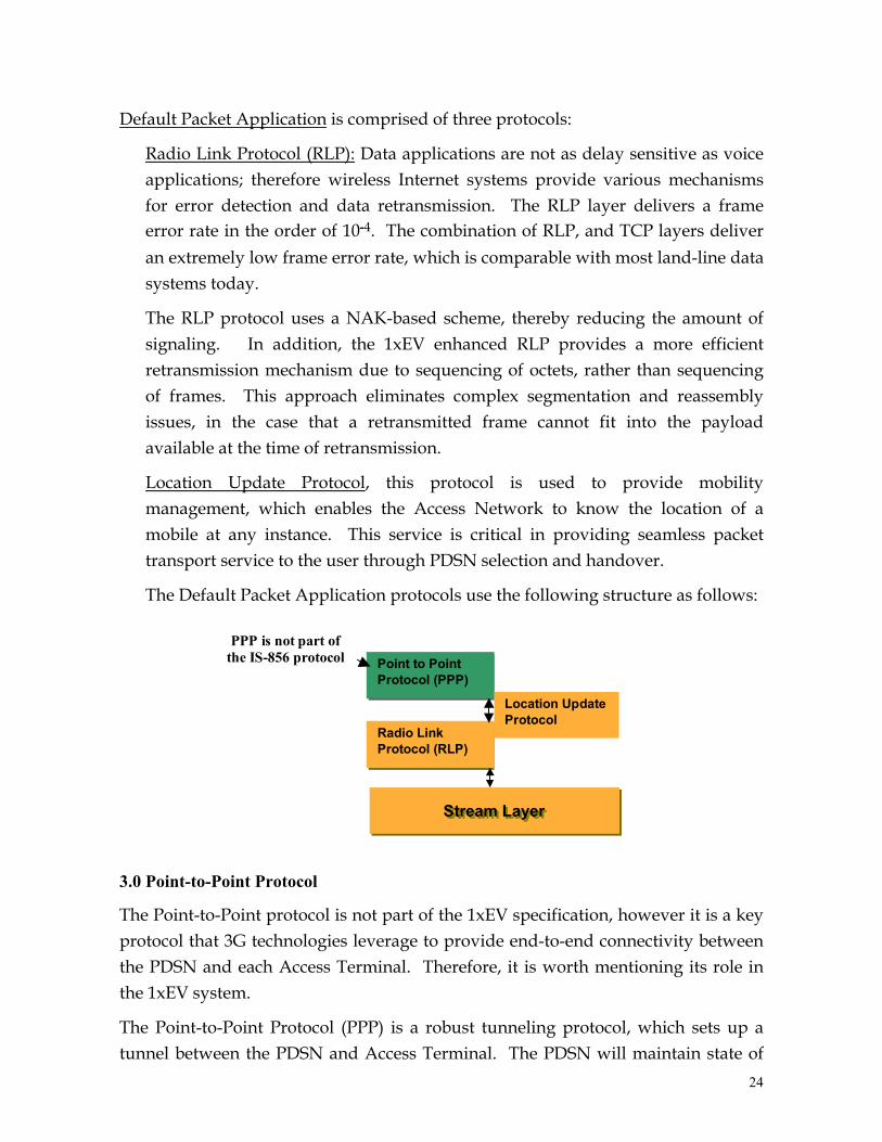
Default Packet Application is comprised of three protocols:
Radio Link Protocol (RLP): Data applications are not as delay sensitive as voice applications; therefore wireless Internet systems provide various mechanisms for error detection and data retransmission. The RLP layer delivers a frame error rate in the order of 10-4. The combination of RLP, and TCP layers deliver an extremely low frame error rate, which is comparable with most land-line data systems today.
The RLP protocol uses a NAK-based scheme, thereby reducing the amount of signaling. In addition, the 1xEV enhanced RLP provides a more efficient retransmission mechanism due to sequencing of octets, rather than sequencing of frames. This approach eliminates complex segmentation and reassembly issues, in the case that a retransmitted frame cannot fit into the payload available at the time of retransmission.
Location Update Protocol, this protocol is used to provide mobility management, which enables the Access Network to know the location of a mobile at any instance. This service is critical in providing seamless packet transport service to the user through PDSN selection and handover.
The Default Packet Application protocols use the following structure as follows:
Radio Link Protocol (RLP)
Stream Layer Stream Layer
Point to Point Protocol (PPP)
Location Update Protocol
PPP is not part of the IS-856 protocol
3.0 Point-to-Point Protocol
The Point-to-Point protocol is not part of the 1xEV specification, however it is a key protocol that 3G technologies leverage to provide end-to-end connectivity between the PDSN and each Access Terminal. Therefore, it is worth mentioning its role in the 1xEV system.
The Point-to-Point Protocol (PPP) is a robust tunneling protocol, which sets up a tunnel between the PDSN and Access Terminal. The PDSN will maintain state of
24

each Access Terminal’s PPP tunnel and forward the user’s traffic through its assigned tunnel. The mobile terminal may move in and out of coverage and the PDSN will maintain the PPP state, thus providing a reliable tunnel and an ‘always on’ experience. For more information on PPP visit the IETF’s website at www.ietf.org and search for RFC 1661.
4.0 1xEV Handoffs
The 1xEV Access Terminal receives data from no more than one Access Point at any given time. Instead of combining transmit energy from multiple Access Points, the Access Terminal is able to rapidly switch from communicating with one Access Point to another.
The Access Terminal measures the channel C/I from all the measurable Pilot channels and requests service from the Access Point with the strongest Pilot signal. This follows the best server rule, where the Access Terminal communicates with the requested Access Point at any given time. The forward link pilot allows the Access Terminal to obtain a rapid and accurate C/I estimate.
The 1xEV reverse link, makes use of soft hand-off mechanisms. The Access Terminal’s transmissions may be received by more than one Access Point, and frame selection is hence made.
The Location Update Message enables the Access Network to connect to the PDSN maintaining the PPP state to the Access Terminal; therefore it can re-route traffic to the Access Terminal immediately upon receiving the Access Terminal’s Location Update Message. This method allows the Access Terminal to maintain it’s same IP address and same PPP connection; therefore allowing a seamless handoff.
4.1 Handoffs to IS-95/1x Systems
The Inter-Operability between 1x and 1xEV Networks are covered in the TIA Standard, IS-878. The following are examples of the handoff scenarios that are possible between 1xEV and 1x systems:
Scenario 1, AT establishes a data session in 1xEV Radio Access Network (RAN). While the AT is Dormant, it performs idle handoff from a 1xEV RAN to another 1xEV RAN.
Scenario 2, While the AT is exchanging data in a 1xEV system, it receives a page for an incoming voice service instance from the 1x system. Since the AT is monitoring
25
the 1x Forward Common Channel periodically, it is able to receive the page for the voice service instance. In this scenario, the AT can be configured to,
1) continue the data call on the 1x system,
2) to abandon the 1xEV data service instance, handoff to the 1x system, and continue with voice only.
Scenario 3, AT is able to receive an SMS while it is exchanging data in the 1xEV system:
SMS is received during the AT’s assigned paging slot or during a broadcast slot
Scenario 4, While the AT is exchanging data in a 1xEV system, it decides to initiate a voice call in the 1x system. In this scenario, the AT can be configured to;
1) continue the data call on the 1x system,
2) to abandon the 1xEV data service instance, handoff to the 1x system, and continue with voice only.
Scenario 5, AT moves away from the coverage area of the 1xEV system into the coverage area of a 1x system. AT performs an Access Network Change from 1xEV system to 1x system.
5.0 Summary
1xEV provides significant performance and economic benefits to the wireless operators. The technology enables operators to offer advanced data services, make best use of their spectrum and network resources, and leads the wireless Internet market by offering high performance packet data services significantly earlier than alternative technologies. The CDMA2000 suite of technologies, exceed the ITU 3G requirements.
1xEV leverages from existing hardware and software design, thus providing significant benefits to the equipment manufacturers. The technology offers short development cycles by supporting a quick production turn-around. 1xEV enables the subscriber manufacturers a strategic differentiation by being first to offer leading-edge user devices.
1xEV unleashes the Internet for the end-users by simplifying the use and implementation of mobile wireless devices, and enabling a variety of mainstream Access Terminals for mobile, portable, and fixed applications. Wireless Web lifestyles, the next Internet revolution, will have a lasting positive effect on 1xEV
26

users by increasing their productivity and improving their quality of life. 1xEV provides an evolution with industry support by using a standardization path under CDMA2000 umbrella.
27