1xev-do for r&s cmu-b88/-b89 - gotrootgotroot.ca/cmu200/cmu_1xev-do_03_v5.10.pdf · 1xev-do for...
TRANSCRIPT

1150.3998.12-03
Test and Measurement Division
Operating Manual
Software Options:
1xEV-DO for R&S® CMU-B88/-B89
R&S® CMU-K88 1150.3998.12 CMU-K839/-K849/-K859/-K869 1200.8300.02/-8400.02/-8500.02/-8600.02
Printed in the Federal Republic of Germany

Dear Customer,
throughout this manual, CMU-K88/-K8x9 is generally used as an abbreviation for software option R&S CMU-K88/-K8x9. The Universal Radio Communication Tester R&S CMU 200/300 is abbreviated as CMU 200/300.
R&S® is a registered trademark of Rohde & Schwarz GmbH & Co. KG. Trade names are trademarks of the respective owners.

CMU-K88/-K839/.../-K869 Contents
1150.3998.12 RE.3 E-3
Tabbed Divider Overview Safety Instructions Certificate of Quality Manuals for Universal Radio Communication Tester CMU What's new in this Revision? Abbreviations Glossary
Tabbed Divider
1 Chapter 1: Installation
2 Chapter 2: Getting Started
3 Chapter 3: Manual Operation
4 Chapter 4: Functions and their Application
5 Chapter 5: Remote Control – Basics
6 Chapter 6: Remote Control – Commands
7 Chapter 7: Remote Control – Program Example
8 Chapter 8: Maintenance
9 Chapter 9: Error Codes
10 Index
R&S CMU Models CMU-K88/-K839/.../-K869
1150.3998.12 RE.4 E-3
1xEV-DO Functionality of R&S CMU Models
1xEV-DO measurements can be performed with the following R&S CMU 200 models: • Universal Radio Communication Tester R&S CMU 200, stock no. 1100.0008.02. If equipped
with the appropriate options (as stated in the relevant sections), this model provides the full 1xEV-DO functionality described in this manual. All 1xEV-DO and 1xEV-DO-related options are supported by this R&S CMU model.
• Non-Signaling Tester R&S CMU 200v30, stock no. 1100.0008.30. The functionality of R&S CMU options which are particularly relevant for production (R&S CMU-K14, R&S CMU-K47, R&S CMU-K48) is included in the basic configuration of the non-signaling tester. With options R&S CMU-B83 and R&S CMU-B88 this model supports all 1xEV-DO TX measurements in Non Signaling mode and also provides a 1xEV-DO generator with channel coding in order to perform single-ended RX tests (with AT-assisted BER evaluation). Optional extensions of the non signaling tester are listed below; note that not all 1xEV-DO options described in this manual are supported.
The different R&S CMU 200 models are also described in the product brochures.
The non-signaling tester also supports the WCDMA, GSM, CDMA2000, and AMPS network standards. In addition Rohde & Schwarz offers a high-end service tester, CMU 200v10, stock no. 1100.0008.10. For details refer to the relevant operating manuals.
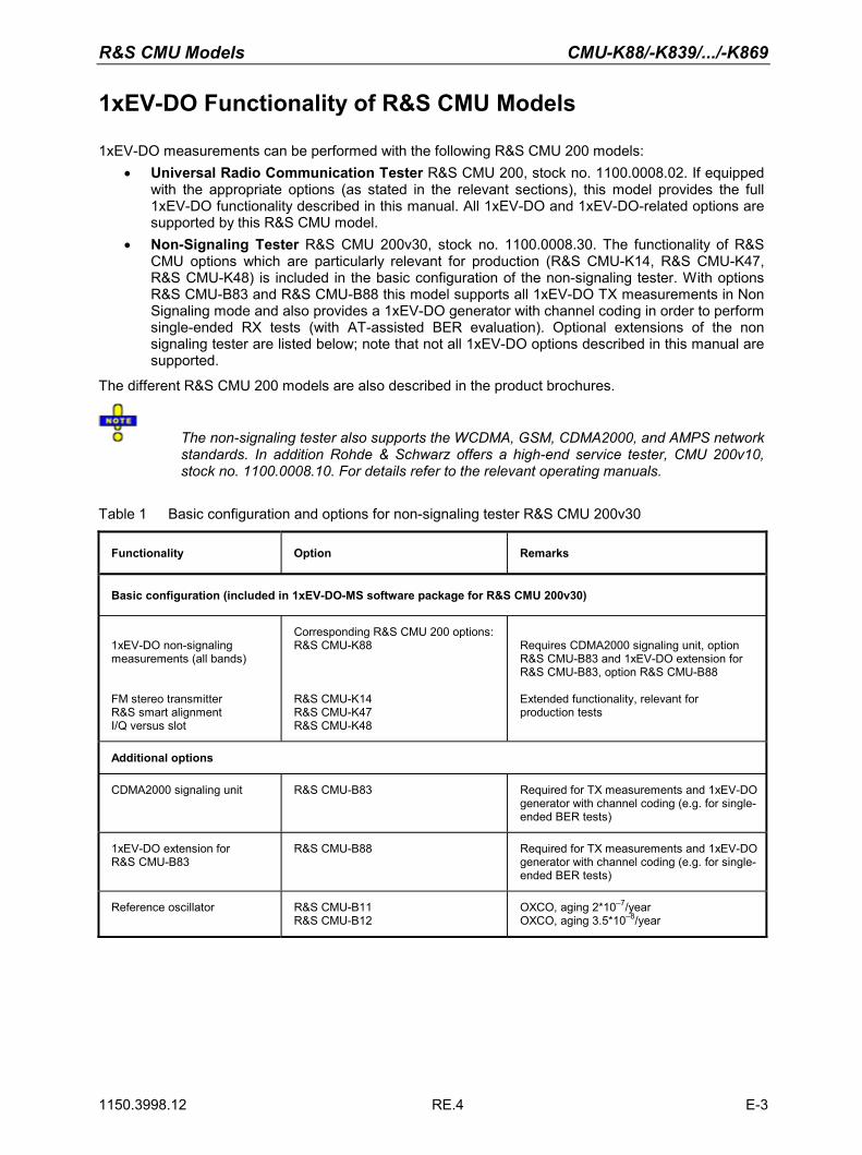
Table 1 Basic configuration and options for non-signaling tester R&S CMU 200v30
Functionality Option Remarks
Basic configuration (included in 1xEV-DO-MS software package for R&S CMU 200v30)
1xEV-DO non-signaling measurements (all bands) FM stereo transmitter R&S smart alignment I/Q versus slot
Corresponding R&S CMU 200 options: R&S CMU-K88 R&S CMU-K14 R&S CMU-K47 R&S CMU-K48
Requires CDMA2000 signaling unit, option R&S CMU-B83 and 1xEV-DO extension for R&S CMU-B83, option R&S CMU-B88 Extended functionality, relevant for production tests
Additional options
CDMA2000 signaling unit R&S CMU-B83 Required for TX measurements and 1xEV-DO generator with channel coding (e.g. for single-ended BER tests)
1xEV-DO extension for R&S CMU-B83
R&S CMU-B88 Required for TX measurements and 1xEV-DO generator with channel coding (e.g. for single-ended BER tests)
Reference oscillator R&S CMU-B11 R&S CMU-B12
OXCO, aging 2*10–7/year OXCO, aging 3.5*10–8/year

CMU-K88/-K839/.../-K869 Table of Contents
1150.3998.12 0.1 E-3
Table of Contents
1 Introduction ..........................................................................................................1.1 1xEV-DO Non-Signaling extension CMU-K88 for units CMU-B88/-B83........................1.1 1xEV-DO Signaling/Non-Signaling extensions CMU-K839/-K849/-K859/-K869 for units CMU-B89/-B83...............................................................................................................1.2 1xEV-DO Non-Signaling extension CMU-K88 for units CMU-B89/-B83........................1.2 Supported CDMA Networks...........................................................................................1.3
Installation Instructions...................................................................................................................1.3
Software Installation or Update ......................................................................................................1.4 Creating a new Software Configuration ...................................................................................1.7
Enabling Software Options .............................................................................................................1.9
2 Getting Started .....................................................................................................2.1
Connecting an Access Terminal and Startup................................................................................2.2
Non-Signaling Measurements.........................................................................................................2.6 Analyzer/Generator Measurement ...........................................................................................2.6
Signaling Mode...............................................................................................................................2.12 Call Setup and Signaling Parameters ....................................................................................2.12 Receiver Quality Measurements ............................................................................................2.16
3 Manual Control .....................................................................................................3.1
Menu Structure .................................................................................................................................3.1 Test Modes ..............................................................................................................................3.1 Status Symbols ........................................................................................................................3.2
Non-Signaling Mode ......................................................................................................3.2 Signaling Mode ..............................................................................................................3.3
Configurations ..........................................................................................................................3.4 Measurement Groups ..............................................................................................................3.4
General Settings...............................................................................................................................3.6
4 Functions and their Application ........................................................................ 4-1
1xEV-DO Module Tests - Overview................................................................................................ 4-2
1xEV-DO Connection Control (Non-Signaling) ............................................................................ 4-3 Connection Control (Non-Signaling) ....................................................................................... 4-3
Network Standard (Connection Control – Standard) .................................................... 4-3 Analyzer Control (Connection Control – Analyzer)........................................................ 4-4

Table of Contents CMU-K88/-K839/.../-K869
1150.3998.12 0.2 E-3
Connection Control – Generator ................................................................................. 4-12 RF Connectors (Connection Control – RF)................................................................. 4-22 Reference Frequency (Connection Control – Sync.) .................................................. 4-25 Trigger (Connection Control – Trigger)....................................................................... 4-27 I/Q-IF Interface (Connection Control – I/Q-IF) ............................................................ 4-30
1xEV-DO Module Tests (Non-Signaling) ..................................................................................... 4-32 Analyzer/Generator Measurement ........................................................................................ 4-32
Softkey Selections ...................................................................................................... 4-33 Measurement Results................................................................................................. 4-35 Analyzer/Generator Configuration............................................................................... 4-36
1xEV-DO Module Tests (Signaling and Non-Signaling) ............................................................ 4-41 Power Measurements ........................................................................................................... 4-41
Softkey Selections ...................................................................................................... 4-42 Measurement Results (NPOWer)............................................................................... 4-45 Measurement Results (SAPPower) ............................................................................ 4-46 Power Configuration ................................................................................................... 4-47
Modulation Measurements.................................................................................................... 4-48 Modulation Parameters ......................................................................................................... 4-48
Softkey Selections ...................................................................................................... 4-51 Measurement Results................................................................................................. 4-53 Modulation Configuration ............................................................................................ 4-63
Spectrum Measurements...................................................................................................... 4-65 Softkey Selections ...................................................................................................... 4-66 Measurement Results................................................................................................. 4-67 Spectrum Configuration .............................................................................................. 4-69
Code Domain Power Measurements .................................................................................... 4-71 Softkey Selections ...................................................................................................... 4-71 Measurement Results................................................................................................. 4-73 Code Domain Power Configuration ............................................................................ 4-78
1xEV-DO Module Tests (Signaling) ............................................................................................. 4-83 Receiver Quality Measurements ........................................................................................... 4-83
Forward and Reverse Link Performance.................................................................... 4-83 Main Menu (Receiver Quality)..................................................................................... 4-85 Test Settings ............................................................................................................... 4-87 Measurement Results................................................................................................. 4-90 Measurement Configurations (Receiver Quality Configuration) ................................. 4-98
Data Application Measurements ......................................................................................... 4-104 Main Menu – RLP Frame and IP Statistics ............................................................... 4-104 Test Settings ............................................................................................................. 4-105 Measurement Results – RLP Frame & IP Statistics ................................................. 4-106 Main Menu – Ping Measurement .............................................................................. 4-107 Measurement Results – Ping.................................................................................... 4-108 Ping Configuration .................................................................................................... 4-109
1xEV-DO Connection Control (Signaling)................................................................................. 4-111

CMU-K88/-K839/.../-K869 Table of Contents
1150.3998.12 0.3 E-3
Connection Control (Signaling) ........................................................................................... 4-111 Connection Settings (Connection Control – Connection) ......................................... 4-113 Handoff Settings (Connection Control – Handoff) .................................................... 4-118 Layer Settings (Connection Control – Layer) ............................................................ 4-119 AN Signal (Connection Control - AN Signal)............................................................. 4-140 Network Parameters (Connection Control – Network).............................................. 4-144 RF Connectors (Connection Control – RF)............................................................... 4-147 Reference Frequency (Connection Control – Sync.) ................................................ 4-152 Trigger (Connection Control – Trigger)..................................................................... 4-156 I/Q-IF Interface (Connection Control – I/Q-IF) .......................................................... 4-158 Analyzer Control (Connection Control – Analyzer).................................................... 4-160 Miscellaneous Settings (Connection Control – Misc.)............................................... 4-166
Marker Control............................................................................................................................. 4-168
5 Remote Control – Basics.....................................................................................5.1
Structure and Order of Commands ................................................................................................5.1
Measurement Control ......................................................................................................................5.2 Measurement Groups ..............................................................................................................5.2 Measurement Statistics............................................................................................................5.3 Specifying Limits ......................................................................................................................5.5
Status Reporting System.................................................................................................................5.5
Special Terms and Notations ..........................................................................................................5.7
6 Remote Control – Commands.............................................................................6.1
General Commands .........................................................................................................................6.1 Option Query............................................................................................................................6.1 Partial Reset.............................................................................................................................6.2 Configuration File Management ...............................................................................................6.2 I/Q-IF Interface.........................................................................................................................6.3 Symbolic Status Event Register Evaluation .............................................................................6.6
Connection Control (Non-Signaling Only).....................................................................................6.7 Band Class – Network Standard ..............................................................................................6.7
NETWork Standard .......................................................................................................6.7 Analyzer ...................................................................................................................................6.8
Subsystem RFANalyzer .................................................................................................6.8 Generator ...............................................................................................................................6.15
Subsystem RFGenerator .............................................................................................6.15 RF Input and Output...............................................................................................................6.37
Subsystem RF Input and Output (External Attenuation at Connectors) ......................6.37 WPOWer (Wide Band Power) ...............................................................................................6.38

Table of Contents CMU-K88/-K839/.../-K869
1150.3998.12 0.4 E-3
Control of Measurement ..............................................................................................6.38 Test Configuration........................................................................................................6.39 Measured Values .........................................................................................................6.40
DM:CLOCk (Synchronization) ................................................................................................6.40 Trigger....................................................................................................................................6.41
Subsystem TRIGger ....................................................................................................6.41 Subsystem RF Selectivity and Rx/Tx Frequency Coupling ....................................................6.45
Measurement Command Groups (Non-Signaling Only).............................................................6.47 MODulation:MQUality (App. Modulation Quality HPSK) ........................................................6.47
Control of Measurement ..............................................................................................6.47 Test Configuration........................................................................................................6.48 Measured Values .........................................................................................................6.54
Common Measurements and Command Groups (Signaling and Non-Signaling) ...................6.56 NPOWer (Narrow Band Power) .............................................................................................6.56
Control of Measurement ..............................................................................................6.56 Test Configuration........................................................................................................6.58 Measured Values .........................................................................................................6.59
SAPPower (Standby and Access Probe Power) ....................................................................6.60 MODulation:OVERview..........................................................................................................6.61
Control of Measurement ..............................................................................................6.61 Test Configuration........................................................................................................6.63 Measured Values .........................................................................................................6.68
MODulation:EVMagnitude (Error Vector Magnitude) .............................................................6.69 Control of Measurement ..............................................................................................6.69 Test Configuration........................................................................................................6.71 Measured Values .........................................................................................................6.74
MODulation:MERRor (Appl. Magnitude Error H-PSK) ...........................................................6.76 Control of Measurement ..............................................................................................6.76 Test Configuration........................................................................................................6.77 Measured Values .........................................................................................................6.80
MODulation:PERRor (Application Phase Error H-PSK).........................................................6.82 Control of Measurement ..............................................................................................6.82 Test Configuration........................................................................................................6.83 Measured Values .........................................................................................................6.86
MODulation:IQANalyzer (IQ Analyzer H-PSK) .......................................................................6.88 Control of Measurement ..............................................................................................6.88 Test Configuration........................................................................................................6.89 Measured Values .........................................................................................................6.91
SPECtrum:ACP (ACP Spectrum) ..........................................................................................6.92 Control of Measurement ..............................................................................................6.92 Test Configuration........................................................................................................6.93 Measured Values .........................................................................................................6.97
CDPower:CDPW (Code Domain Power) .............................................................................6.100 Control of Measurement ............................................................................................6.100 Test Configuration......................................................................................................6.101

CMU-K88/-K839/.../-K869 Table of Contents
1150.3998.12 0.5 E-3
Measured Values .......................................................................................................6.106 CDPower:PCDep (Peak Code Domain Error Power) ..........................................................6.111
Control of Measurement ............................................................................................6.111 Test Configuration......................................................................................................6.112 Measured Values .......................................................................................................6.115
CDPower:CHPW (Channel Power)......................................................................................6.120 Control of measurement ............................................................................................6.120 Test Configuration......................................................................................................6.121 Measured Values .......................................................................................................6.125
Measurement Command Groups (Signaling Only) ...................................................................6.133 RxQuality (Receiver Quality) ................................................................................................6.133
Control of Measurement - Common Commands.......................................................6.133 Test Configuration......................................................................................................6.134
Data Applications - RLP Frame / IP Statistics and Ping.......................................................6.152 Control of Measurement - Common Commands.......................................................6.152 Subsystem PING:CONTrol ........................................................................................6.154
Connection Control (Signaling Only) .........................................................................................6.157 Subsystem Signaling (Connection Setup and Cleardown)...................................................6.158
Subsystem AT Information ........................................................................................6.160 Subsystem Handoff..............................................................................................................6.161 Subsystem Layer..................................................................................................................6.161
Subsystem Default Signaling Application ..................................................................6.162 Subsystem Default Test Application ..........................................................................6.163 Subsystem Enhanced Test Application .....................................................................6.169 Subsystem Default Packet Application ......................................................................6.172 Subsystem Stream Layer...........................................................................................6.179 Subsystem Session Layer .........................................................................................6.180 Subsystem Connection Layer ....................................................................................6.181 Subsystem MAC Layer ..............................................................................................6.182 Subsystem Physical Layer .........................................................................................6.192
Subsystem ANSignal............................................................................................................6.192 Subsystem Power Control .........................................................................................6.194 Subsystem Sector......................................................................................................6.195 Subsystem Access Network Properties.....................................................................6.197 Subsystem AT Forward Packet Activity .....................................................................6.198
Subsystem Band Class – NETWork Standard ....................................................................6.198 Subsystem RFANalyzer .......................................................................................................6.204
Subsystem LEVel.......................................................................................................6.205 Subsystem SUBType.................................................................................................6.205 Subsystem CCFilter (Code Channel Filter)................................................................6.206 Subsystem DCHannel (Data Channel Modulation)....................................................6.208
External Synchronization......................................................................................................6.209 Subsystem ESYNc.....................................................................................................6.209
Trigger..................................................................................................................................6.211 Subsystem TRIGger ..................................................................................................6.211

Table of Contents CMU-K88/-K839/.../-K869
1150.3998.12 0.6 E-3
Subsystem Miscellaneous (User Guidance and RF Selectivity) ..........................................6.214 Subsystem User Guidance (Connection Control Behavior).......................................6.214 Subsystem RF Selectivity ..........................................................................................6.214 Low Spur Mode..........................................................................................................6.215
Subsystem WPOWer (Wide Band Power) ..........................................................................6.215 Control of Measurement ............................................................................................6.215 Test Configuration......................................................................................................6.216
List of Commands ........................................................................................................................6.218
7 Remote Control – Program Example..................................................................7.1
Sample Program (Non-Signaling) ...................................................................................................7.1
Sample Programs (Signaling) .........................................................................................................7.5 Reverse Test Application Call and Queries for CDPower for different Channels ....................7.5 Default Packet Application Call and Queries for RLP/IP Statistics ..........................................7.8
8 Maintenance .........................................................................................................8.1
9 Error Codes ..........................................................................................................9.1
Index........................................................................................................................10.1

CMU-K88/-K839/.../-K869 Manuals
1150.3998.12 0.7 E-3
Contents of Manuals for Universal Radio Communication Tester CMU
The user documentation for the R&S CMU 200/300 is divided into an operating manual for the basic instrument (including options CMU-B41, CMU-B17) and separate manuals for individual software and hardware options. The complete documentation is available on CD-ROM, stock no. PD 0757.7746.2x. The latest revisions of all manuals are also posted on the CMU Customer Web on GLORIS.
For an overview and order information about printed manuals refer to the beginning of the Quick Start Guide. The latest revisions of the manuals are also posted on the CMU Customer Web on GLORIS.
Operating Manual CMU-K88/-K839/-K849/-K859/-K869 (Software Options for CMU-B88/-B89) The present operating manual describes the application of the CMU for 1xEV-DO mobile tests. It gives comprehensive information about the operating concept and about manual and remote control of the CMU tester. Typical measurement tasks are explained in detail using the functions offered by the graphical user interface and a selection of program examples.
The manual is organized as follows:
Chapter 1 Describes the steps necessary for installing the software and putting the instru-ment into operation.
Chapter 2 Gives an introduction to the application of the CMU for 1xEV-DO mobile tests and presents some typical measurement examples.
Chapter 3 Gives an overview of the user interface and describes the concepts of measure-ment control and instrument configuration.
Chapter 4 Represents the reference chapter providing detailed information on all functions of the user interface and their application.
Chapter 5 Describes the basics of remote control of the instrument for 1xEV-DO mobile tests.
Chapter 6 Lists all remote control commands defined for 1xEV-DO mobile tests. At the end of the chapter the commands are grouped according to their function (measurement groups or configurations) and sorted in alphabetical order.
Chapter 7 Contains program examples.
Chapter 8 Describes preventive maintenance.
Chapter 9 Contains a list of error codes
Chapter 10 Contains an index for the operating manual.

Manuals CMU-K88/-K839/.../-K869
1150.3998.12 0.8 E-3
What's new in this Revision... This operating manual describes version V4.32 of the 1xEV-DO firmware package. The essential new features compared to version V4.20 are listed below and in the suppplement for V4.35 and V4.52.
New Features Description Refer to...
Support for Network Revision A
The related Configuration Control options and Receiver Quality Measurements (e.g. Reverse Link Performance) were modified to reflect the Network Revision A / phys. signal subtype 2 measurements.
Chapter 4
Data Packet Applications
The new RLP Frame & IP Statistics and Ping applications are introduced. RLP Frame & IP Statistics is an application of options R&S CMU-K8x9 and R&S CMU-K87 which can be used to monitor test scenarios using the Mobile IP pro-tocol type. The Ping menu configures the R&S CMU to send repeated echo requests of configurable size (pings) to the mobile. The application waits for the echo and displays the ping statistics including the possible source of connec-tion errors.
Chapter 4
De-spreading mode for I/Q Analyzer HPSK Modulation Application
The de-spreading mode allows the analysis of the I/Q signal either as the composite signal on the chip level (de-spread set to OFF), or only the data channel on the symbol level (de-spread set to Data Symbols)
Chapter 4
High Power AWGN mode
The AWGN Mode sets the AWGN power level for signaling and non-signaling 1xEV-DO testing. A High Power range allowing an AWGN level range from +11.7 dB to –12.0 dB is introduced.
Chapter 4
Access Probe Sequence enhancements
Additional parameters for access probe sequences on the Access Channel Protocols of the MAC layer were intro-duced.
Chapter 4
RRI channel gain transi-tion parameters for Sub-type 3 Reverse Traffic Ch. MAC Protocol
The RRI channel gain pre- and post-transition parameters indicate the ratio of the power level of the RRI channel to the power level of the reverse Pilot channel for the transmit-ted subpackets (0 to 3).
Chapter 4
CDMA system time synchronization parame-ters
For signaling measurements, e.g. CDMA2000 1xRTT / 1xEV-DO hybrid mode testing, the Connection Control was enhanced to synchronize the CMU and the connected mo-bile with the CDMA system time of another CMU.
Chapter 4
Low Spur Mode The Low Spur Mode is introduced to increase the signal-to-noise ratio for the signal analyzer with high Tx levels.
Chapter 4

CMU-K88/-K839/.../-K869 Manuals
1150.3998.12 0.9 E-3
Frequently Used Abbreviations 3GPP2 3rd Generation Partnership Project 2 8-PSK 8-Phase Shift Keying Abs. Absolute AN Access Network AT Access Terminal Avg. Average AWGN Additive White Gaussian Noise BPSK Binary Phase Shift Keying BS Base Station CDMA Code Division Multiple Access CDP Code Domain Power Chan. Channel CH Channel Channel. Channelization CHAP Challenge-Handshake Authentication Protocol CRC Cyclic Redundancy Code Curr. Current Disp. Display DRC Data Rate Control DRCLock Data Rate Control Lock DUT Device under Test EIRP Effective Isotropic Radiated Power Err. Error ESN Electronic Serial Number EVM Error Vector Magnitude Ext., Extern. External FETAP Forward Enhanced Test Application Protocol FFT Fast Fourier Transform Freq. Frequency FTAP Forward Test Application Protocol GPIB General Purpose Interface Bus = IEEE488 Bus HPSK Hybrid Phase Shift Keying I In-phase IF Interface IF Intermediate Frequency Int. Internal Lev. Level LSB Least Significant Bits MAC Media Access Control Magn. Magnitude Max. Maximum (e.g. Level) ME Magnitude Error MEID Mobile Equipment Identifier Meas. Measurement Min. Minimum MSB Most Significant Bits MIP Mobile IP OAT Other Access Terminals Ovw Overview PAP Password Authentication Protocol PCS Personal Communications Services PCDE Peak Code Domain Error PDSN Packet Data Serving Node PE Phase Error PER Packet Error Rate Pk. Peak PPP Point-to-Point Protocol Q Quadrature-phase QPSK Quadrature Phase Shift Keying RA Reverse Activity RAB Reverse Activity Bit RBW Resolution Bandwidth Ref. Reference Rel. Relative RETAP Reverse Enhanced Test Application Protocol RF Radio Frequency RLP Radio Link Protocol RMS Root Mean Square RPC Reverse Power Control

Abbreviations CMU-K88/-K839/.../-K869
1150.3998.12 0.10 E-3
RRI Reverse Rate Indicator RTAP Reverse Test Application Protocol RX Receiver Scr. Scrambling SW Software Sym. Symbol Sync. Synchronous Synch. Synchronization TDM Time Division Multiplexing Trg. Trigger TX Transmitter UATI Unicast Access Terminal Identifier Vect. Vector

CMU-K88/-K839/.../-K869 Glossary
1150.3998.12 0.11 E-3
Glossary of Terms
The following list contains definitions of terms that are often used throughout this manual. Access channel A reverse communication channel used by a mobile station to communicate
to a base station. The Access Channel is used for short signalling message exchanges, such as call originations, responses to pages, and registrations. The Access Channel is a slotted random access channel.
Carrier feedthrough Ratio of the I/Q offset vector (i.e. the estimated DC offset of the measured signal) to the average offset-corrected signal vector.
Carrier frequency error Deviation of the mobile’s actually received carrier frequency from the as-signed frequency received from the base station.
Chip rate Product of the symbol rate and the spreading factor, which is equivalent to the spreading rate of the channel. For the CDMA2000® 1xEV-DO system a fixed chip rate of 1.2288 Mcps is specified.
Code domain The entire set of channelization codes involved in a CDMA2000® 1xEV-DO signal configuration. Measuring a parameter in code domain means to de-termine its values as a function of the individual channelization codes.
Code domain error Ratio of the RMS-averaged power of the error vector projected onto the code domain to the RMS-averaged power of the composite reference sig-nal, expressed in dB.
Code domain power Power in the individual code channels normalized to the power of the com-posite signal, expressed in dB.
Control Channel cycle The Control Channel cycle is defined as a 256 slot period, synchronous with CDMA system time; i.e., there is an integer multiple of 256 slots between the beginning of a cycle and the beginning of CDMA system time.
Crest factor Peak to average ratio: ratio of the peak transmit power in a slot (peak enve-lope power) to the average transmit power in a slot.
Cyclic redundancy code (CRC)
A class of linear error detecting codes which generate parity check bits by finding the remainder of a polynomial division.
Eb Average energy per information bit for the Sync Channel, Paging Channel, or Forward Traffic Channel at the mobile station antenna connector.
Eb/Nt The ratio of the combined received energy per bit to the effective noise power spectral density for the Control Channel, or Forward Traffic Channel at the mobile station antenna connector.
Error vector magnitude Difference vector connecting the measured and the ideal modulated signal vector. The error vector magnitude (EVM) is the critical quantity to assess the modulation accuracy of the mobile’s transmitter.
Forward Test Application Protocol (FTAP)
This protocol specifies the procedures and messages to control the Forward Traffic Channel and to configure reverse channels associated with the For-ward Traffic Channel. It specifies generation and transmission of test pack-ets sent on the Forward and Reverse Traffic Channels for the purpose of testing the Forward Traffic Channel. It also specifies statistics collection procedures for certain access terminal statistics.
I/Q imbalance Difference between the estimated I and Q amplitudes of the measured sig-nal, normalized and expressed in dB units.
MAC Used in two contexts. 1) The MAC laver is the Media Access Control layer that coordinates the operation of the physical layer with the needs of the traffic and signalling systems in the upper layers. 2) As a region within the forward link 1xEV-DO slot format, that contains Reverse Control Control bits

Glossary CMU-K88/-K839/.../-K869
1150.3998.12 0.12 E-3
and other indicators. This region is repeated four times within a slot.
Magnitude error Difference in magnitude between the measured and the ideal modulated signal vector, normalized to the magnitude of the ideal vector.
Maximum power Operating mode where the mobile is set to its maximum power control level.
Minimum power Operating mode where the mobile is set to its minimum power control level.
Modulation accuracy Ability of the mobile transmitter to generate an ideally modulated signal.
Nt The effective noise power spectral density at the mobile station antenna connector.
Peak code domain error Maximum of the code domain errors for all codes in the domain, expressed in dB.
Phase error Difference in phase between the measured and the ideal modulated signal vector.
Pilot Channel The Reverse Traffic Channel consists of a Pilot Channel, an RRI Channel, a DRC Channel, an ACK Channel, and a Data Channel. Per definition, the access terminal transmits unmodulated symbols with a binary value of ‘0’ on the Pilot Channel. The transmission of the Pilot Chan-nel and the RRI Channel are both time multiplexed on the same Walsh channel. The Pilot Channel and the RRI Channel are transmitted at the same power level.
Reverse Power Control bit A bit sent (within the MAC region) in every slot. Each bit commands the access terminal to raise or lower its transmit power.
RRI (Reverse Rate Indicator)
The Reverse Traffic Channel consists of a Pilot Channel, an RRI Channel, a DRC Channel, an ACK Channel, and a Data Channel. During a connection, the RRI Channel is transmitted over the first 256 chips of every slot. The RRI Channel "punctures" the Pilot Channel and both channels are transmitted at the same power level. The RRI channel power test verifies that the RRI Channel is transmitted at the same power level as the Pilot Channel.
Waveform quality Normalized correlated power between the actual and the ideal waveform, sampled at the constellation points. The waveform quality (ρ factor) is a measure of the modulation accuracy. For an ideal transmitter (ideal correla-tion), it is equal to 1, otherwise it is a positive number smaller than 1.
References
• TIA/EIA/IS-856-A, cdma2000® High Rate Packet Data Air Interface Specification
• TIA/EIA/IS-866-A, Recommended Minimum Performance Standards for cdma2000® High Rate Packet Data Access Terminal
• TIA/EIA/IS-890-A, Test Application Specification (TAS) for High Rate Packet Data Air Interface
• TIA-1030-B, Band Class Specification for cdma2000® Spread Spectrum Systems

1171.0000.42-05.00 Page 1
Basic Safety Instructions Always read through and comply with the following safety instructions!
All plants and locations of the Rohde & Schwarz group of companies make every effort to keep the safety standards of our products up to date and to offer our customers the highest possible degree of safety. Our products and the auxiliary equipment they require are designed, built and tested in accordance with the safety standards that apply in each case. Compliance with these standards is continuously monitored by our quality assurance system. The product described here has been designed, built and tested in accordance with the attached EC Certificate of Conformity and has left the manufacturer’s plant in a condition fully complying with safety standards. To maintain this condition and to ensure safe operation, you must observe all instructions and warnings provided in this manual. If you have any questions regarding these safety instructions, the Rohde & Schwarz group of companies will be happy to answer them.
Furthermore, it is your responsibility to use the product in an appropriate manner. This product is designed for use solely in industrial and laboratory environments or, if expressly permitted, also in the field and must not be used in any way that may cause personal injury or property damage. You are responsible if the product is used for any intention other than its designated purpose or in disregard of the manufacturer's instructions. The manufacturer shall assume no responsibility for such use of the product.
The product is used for its designated purpose if it is used in accordance with its product documentation and within its performance limits (see data sheet, documentation, the following safety instructions). Using the product requires technical skills and a basic knowledge of English. It is therefore essential that only skilled and specialized staff or thoroughly trained personnel with the required skills be allowed to use the product. If personal safety gear is required for using Rohde & Schwarz products, this will be indicated at the appropriate place in the product documentation. Keep the basic safety instructions and the product documentation in a safe place and pass them on to the subsequent users.
Observing the safety instructions will help prevent personal injury or damage of any kind caused by dangerous situations. Therefore, carefully read through and adhere to the following safety instructions before and when using the product. It is also absolutely essential to observe the additional safety instructions on personal safety, for example, that appear in relevant parts of the product documentation. In these safety instructions, the word "product" refers to all merchandise sold and distributed by the Rohde & Schwarz group of companies, including instruments, systems and all accessories.
Symbols and safety labels
Notice, general danger location
Observe product documentation
Caution when handling heavy equipment
Danger of electric shock
Warning! Hot surface
PE terminal Ground Ground terminal
Be careful when handling electrostatic sensitive devices
ON/OFF supply voltage
Standby indication
Direct current (DC)
Alternating current (AC)
Direct/alternating current (DC/AC)
Device fully protected by double (reinforced) insulation

Basic Safety Instructions
1171.0000.42-05.00 Page 2
Tags and their meaning
The following signal words are used in the product documentation in order to warn the reader about risks and dangers.
indicates a hazardous situation which, if not avoided, will result in death or serious injury.
indicates a hazardous situation which, if not avoided, could result in death or serious injury.
indicates a hazardous situation which, if not avoided, could result in minor or moderate injury.
indicates the possibility of incorrect operation which can result in damage to the product. In the product documentation, the word ATTENTION is used synonymously.
These tags are in accordance with the standard definition for civil applications in the European Economic Area. Definitions that deviate from the standard definition may also exist in other economic areas or military applications. It is therefore essential to make sure that the tags described here are always used only in connection with the related product documentation and the related product. The use of tags in connection with unrelated products or documentation can result in misinterpretation and in personal injury or material damage.
Operating states and operating positions
The product may be operated only under the operating conditions and in the positions specified by the manufacturer, without the product's ventilation being obstructed. If the manufacturer's specifications are not observed, this can result in electric shock, fire and/or serious personal injury or death. Applicable local or national safety regulations and rules for the prevention of accidents must be observed in all work performed.
1. Unless otherwise specified, the following requirements apply to Rohde & Schwarz products: predefined operating position is always with the housing floor facing down, IP protection 2X, pollution severity 2, overvoltage category 2, use only indoors, max. operating altitude 2000 m above sea level, max. transport altitude 4500 m above sea level. A tolerance of ±10 % shall apply to the nominal voltage and ±5 % to the nominal frequency.
2. Do not place the product on surfaces, vehicles, cabinets or tables that for reasons of weight or stability are unsuitable for this purpose. Always follow the manufacturer's installation instructions when installing the product and fastening it to objects or structures (e.g. walls and shelves). An installation that is not carried out as described in the product documentation could result in personal injury or death.
3. Do not place the product on heat-generating devices such as radiators or fan heaters. The ambient temperature must not exceed the maximum temperature specified in the product documentation or in the data sheet. Product overheating can cause electric shock, fire and/or serious personal injury or death.

Basic Safety Instructions
1171.0000.42-05.00 Page 3
Electrical safety
If the information on electrical safety is not observed either at all to the extent necessary, electric shock, fire and/or serious personal injury or death may occur.
1. Prior to switching on the product, always ensure that the nominal voltage setting on the product matches the nominal voltage of the AC supply network. If a different voltage is to be set, the power fuse of the product may have to be changed accordingly.
2. In the case of products of safety class I with movable power cord and connector, operation is permitted only on sockets with an earthing contact and protective earth connection.
3. Intentionally breaking the protective earth connection either in the feed line or in the product itself is not permitted. Doing so can result in the danger of an electric shock from the product. If extension cords or connector strips are implemented, they must be checked on a regular basis to ensure that they are safe to use.
4. If the product does not have a power switch for disconnection from the AC supply network, the plug of the connecting cable is regarded as the disconnecting device. In such cases, always ensure that the power plug is easily reachable and accessible at all times (corresponding to the length of connecting cable, approx. 2 m). Functional or electronic switches are not suitable for providing disconnection from the AC supply network. If products without power switches are integrated into racks or systems, a disconnecting device must be provided at the system level.
5. Never use the product if the power cable is damaged. Check the power cable on a regular basis to ensure that it is in proper operating condition. By taking appropriate safety measures and carefully laying the power cable, you can ensure that the cable will not be damaged and that no one can be hurt by, for example, tripping over the cable or suffering an electric shock.
6. The product may be operated only from TN/TT supply networks fused with max. 16 A (higher fuse only after consulting with the Rohde & Schwarz group of companies).
7. Do not insert the plug into sockets that are dusty or dirty. Insert the plug firmly and all the way into the socket. Otherwise, sparks that result in fire and/or injuries may occur.
8. Do not overload any sockets, extension cords or connector strips; doing so can cause fire or electric shocks.
9. For measurements in circuits with voltages Vrms > 30 V, suitable measures (e.g. appropriate measuring equipment, fusing, current limiting, electrical separation, insulation) should be taken to avoid any hazards.
10. Ensure that the connections with information technology equipment, e.g. PCs or other industrial computers, comply with the IEC60950-1/EN60950-1 or IEC61010-1/EN 61010-1 standards that apply in each case.
11. Unless expressly permitted, never remove the cover or any part of the housing while the product is in operation. Doing so will expose circuits and components and can lead to injuries, fire or damage to the product.
12. If a product is to be permanently installed, the connection between the PE terminal on site and the product's PE conductor must be made first before any other connection is made. The product may be installed and connected only by a licensed electrician.
13. For permanently installed equipment without built-in fuses, circuit breakers or similar protective devices, the supply circuit must be fused in such a way that anyone who has access to the product, as well as the product itself, is adequately protected from injury or damage.

Basic Safety Instructions
1171.0000.42-05.00 Page 4
14. Use suitable overvoltage protection to ensure that no overvoltage (such as that caused by a bolt of lightning) can reach the product. Otherwise, the person operating the product will be exposed to the danger of an electric shock.
15. Any object that is not designed to be placed in the openings of the housing must not be used for this purpose. Doing so can cause short circuits inside the product and/or electric shocks, fire or injuries.
16. Unless specified otherwise, products are not liquid-proof (see also section "Operating states and operating positions", item 1. Therefore, the equipment must be protected against penetration by liquids. If the necessary precautions are not taken, the user may suffer electric shock or the product itself may be damaged, which can also lead to personal injury.
17. Never use the product under conditions in which condensation has formed or can form in or on the product, e.g. if the product has been moved from a cold to a warm environment. Penetration by water increases the risk of electric shock.
18. Prior to cleaning the product, disconnect it completely from the power supply (e.g. AC supply network or battery). Use a soft, non-linting cloth to clean the product. Never use chemical cleaning agents such as alcohol, acetone or diluents for cellulose lacquers.
Operation
1. Operating the products requires special training and intense concentration. Make sure that persons who use the products are physically, mentally and emotionally fit enough to do so; otherwise, injuries or material damage may occur. It is the responsibility of the employer/operator to select suitable personnel for operating the products.
2. Before you move or transport the product, read and observe the section titled "Transport".
3. As with all industrially manufactured goods, the use of substances that induce an allergic reaction (allergens) such as nickel cannot be generally excluded. If you develop an allergic reaction (such as a skin rash, frequent sneezing, red eyes or respiratory difficulties) when using a Rohde & Schwarz product, consult a physician immediately to determine the cause and to prevent health problems or stress.
4. Before you start processing the product mechanically and/or thermally, or before you take it apart, be sure to read and pay special attention to the section titled "Waste disposal", item 1.
5. Depending on the function, certain products such as RF radio equipment can produce an elevated level of electromagnetic radiation. Considering that unborn babies require increased protection, pregnant women must be protected by appropriate measures. Persons with pacemakers may also be exposed to risks from electromagnetic radiation. The employer/operator must evaluate workplaces where there is a special risk of exposure to radiation and, if necessary, take measures to avert the potential danger.
6. Should a fire occur, the product may release hazardous substances (gases, fluids, etc.) that can cause health problems. Therefore, suitable measures must be taken, e.g. protective masks and protective clothing must be worn.
7. If a laser product (e.g. a CD/DVD drive) is integrated into a Rohde & Schwarz product, absolutely no other settings or functions may be used as described in the product documentation. The objective is to prevent personal injury (e.g. due to laser beams).

Basic Safety Instructions
1171.0000.42-05.00 Page 5
Repair and service
1. The product may be opened only by authorized, specially trained personnel. Before any work is performed on the product or before the product is opened, it must be disconnected from the AC supply network. Otherwise, personnel will be exposed to the risk of an electric shock.
2. Adjustments, replacement of parts, maintenance and repair may be performed only by electrical experts authorized by Rohde & Schwarz. Only original parts may be used for replacing parts relevant to safety (e.g. power switches, power transformers, fuses). A safety test must always be performed after parts relevant to safety have been replaced (visual inspection, PE conductor test, insulation resistance measurement, leakage current measurement, functional test). This helps ensure the continued safety of the product.
Batteries and rechargeable batteries/cells
If the information regarding batteries and rechargeable batteries/cells is not observed either at all or to the extent necessary, product users may be exposed to the risk of explosions, fire and/or serious personal injury, and, in some cases, death. Batteries and rechargeable batteries with alkaline electrolytes (e.g. lithium cells) must be handled in accordance with the EN 62133 standard.
1. Cells must not be taken apart or crushed.
2. Cells or batteries must not be exposed to heat or fire. Storage in direct sunlight must be avoided. Keep cells and batteries clean and dry. Clean soiled connectors using a dry, clean cloth.
3. Cells or batteries must not be short-circuited. Cells or batteries must not be stored in a box or in a drawer where they can short-circuit each other, or where they can be short-circuited by other conductive materials. Cells and batteries must not be removed from their original packaging until they are ready to be used.
4. Keep cells and batteries out of the hands of children. If a cell or a battery has been swallowed, seek medical aid immediately.
5. Cells and batteries must not be exposed to any mechanical shocks that are stronger than permitted.
6. If a cell develops a leak, the fluid must not be allowed to come into contact with the skin or eyes. If contact occurs, wash the affected area with plenty of water and seek medical aid.
7. Improperly replacing or charging cells or batteries that contain alkaline electrolytes (e.g. lithium cells) can cause explosions. Replace cells or batteries only with the matching Rohde & Schwarz type (see parts list) in order to ensure the safety of the product.
8. Cells and batteries must be recycled and kept separate from residual waste. Rechargeable batteries and normal batteries that contain lead, mercury or cadmium are hazardous waste. Observe the national regulations regarding waste disposal and recycling.
Transport
1. The product may be very heavy. Therefore, the product must be handled with care. In some cases, the user may require a suitable means of lifting or moving the product (e.g. with a lift-truck) to avoid back or other physical injuries.

Informaciones elementales de seguridad
1171.0000.42-05.00 Page 6
2. Handles on the products are designed exclusively to enable personnel to transport the product. It is therefore not permissible to use handles to fasten the product to or on transport equipment such as cranes, fork lifts, wagons, etc. The user is responsible for securely fastening the products to or on the means of transport or lifting. Observe the safety regulations of the manufacturer of the means of transport or lifting. Noncompliance can result in personal injury or material damage.
3. If you use the product in a vehicle, it is the sole responsibility of the driver to drive the vehicle safely and properly. The manufacturer assumes no responsibility for accidents or collisions. Never use the product in a moving vehicle if doing so could distract the driver of the vehicle. Adequately secure the product in the vehicle to prevent injuries or other damage in the event of an accident.
Waste disposal
1. If products or their components are mechanically and/or thermally processed in a manner that goes beyond their intended use, hazardous substances (heavy-metal dust such as lead, beryllium, nickel) may be released. For this reason, the product may only be disassembled by specially trained personnel. Improper disassembly may be hazardous to your health. National waste disposal regulations must be observed.
2. If handling the product releases hazardous substances or fuels that must be disposed of in a special way, e.g. coolants or engine oils that must be replenished regularly, the safety instructions of the manufacturer of the hazardous substances or fuels and the applicable regional waste disposal regulations must be observed. Also observe the relevant safety instructions in the product documentation. The improper disposal of hazardous substances or fuels can cause health problems and lead to environmental damage.
Informaciones elementales de seguridad Es imprescindible leer y observar las siguientes instrucciones e informaciones de seguridad!
El principio del grupo de empresas Rohde & Schwarz consiste en tener nuestros productos siempre al día con los estándares de seguridad y de ofrecer a nuestros clientes el máximo grado de seguridad. Nuestros productos y todos los equipos adicionales son siempre fabricados y examinados según las normas de seguridad vigentes. Nuestro sistema de garantía de calidad controla constantemente que sean cumplidas estas normas. El presente producto ha sido fabricado y examinado según el certificado de conformidad adjunto de la UE y ha salido de nuestra planta en estado impecable según los estándares técnicos de seguridad. Para poder preservar este estado y garantizar un funcionamiento libre de peligros, el usuario deberá atenerse a todas las indicaciones, informaciones de seguridad y notas de alerta. El grupo de empresas Rohde & Schwarz está siempre a su disposición en caso de que tengan preguntas referentes a estas informaciones de seguridad.
Además queda en la responsabilidad del usuario utilizar el producto en la forma debida. Este producto está destinado exclusivamente al uso en la industria y el laboratorio o, si ha sido expresamente autorizado, para aplicaciones de campo y de ninguna manera deberá ser utilizado de modo que alguna persona/cosa pueda sufrir daño. El uso del producto fuera de sus fines definidos o sin tener en cuenta las instrucciones del fabricante queda en la responsabilidad del usuario. El fabricante no se hace en ninguna forma responsable de consecuencias a causa del mal uso del producto.

Informaciones elementales de seguridad
1171.0000.42-05.00 Page 7
Se parte del uso correcto del producto para los fines definidos si el producto es utilizado conforme a las indicaciones de la correspondiente documentación del producto y dentro del margen de rendimiento definido (ver hoja de datos, documentación, informaciones de seguridad que siguen). El uso del producto hace necesarios conocimientos técnicos y ciertos conocimientos del idioma inglés. Por eso se debe tener en cuenta que el producto solo pueda ser operado por personal especializado o personas instruidas en profundidad con las capacidades correspondientes. Si fuera necesaria indumentaria de seguridad para el uso de productos de Rohde & Schwarz, encontraría la información debida en la documentación del producto en el capítulo correspondiente. Guarde bien las informaciones de seguridad elementales, así como la documentación del producto, y entréguelas a usuarios posteriores.
Tener en cuenta las informaciones de seguridad sirve para evitar en lo posible lesiones o daños por peligros de toda clase. Por eso es imprescindible leer detalladamente y comprender por completo las siguientes informaciones de seguridad antes de usar el producto, y respetarlas durante el uso del producto. Deberán tenerse en cuenta todas las demás informaciones de seguridad, como p. ej. las referentes a la protección de personas, que encontrarán en el capítulo correspondiente de la documentación del producto y que también son de obligado cumplimiento. En las presentes informaciones de seguridad se recogen todos los objetos que distribuye el grupo de empresas Rohde & Schwarz bajo la denominación de "producto", entre ellos también aparatos, instalaciones así como toda clase de accesorios.
Símbolos y definiciones de seguridad
Aviso: punto de peligro general
Observar la documentación del producto
Atención en el manejo de dispositivos de peso elevado
Peligro de choque eléctrico
Adver-tencia: superficie caliente
Conexión a conductor de protección
Conexión a tierra
Conexión a masa
Aviso: Cuidado en el manejo de dispositivos sensibles a la electrostática (ESD)
Tensión de alimentación de PUESTA EN MARCHA / PARADA
Indicación de estado de espera (Standby)
Corriente continua (DC)
Corriente alterna (AC)
Corriente continua / Corriente alterna (DC/AC)
El aparato está protegido en su totalidad por un aislamiento doble (reforzado)

Informaciones elementales de seguridad
1171.0000.42-05.00 Page 8
Palabras de señal y su significado
En la documentación del producto se utilizan las siguientes palabras de señal con el fin de advertir contra riesgos y peligros.
PELIGRO identifica un peligro inminente con riesgo elevado que provocará muerte o lesiones graves si no se evita.
ADVERTENCIA identifica un posible peligro con riesgo medio de provocar muerte o lesiones (graves) si no se evita.
ATENCIÓN identifica un peligro con riesgo reducido de provocar lesiones leves o moderadas si no se evita.
AVISO indica la posibilidad de utilizar mal el producto y, como consecuencia, dañarlo. En la documentación del producto se emplea de forma sinónima el término CUIDADO.
Las palabras de señal corresponden a la definición habitual para aplicaciones civiles en el área económica europea. Pueden existir definiciones diferentes a esta definición en otras áreas económicas o en aplicaciones militares. Por eso se deberá tener en cuenta que las palabras de señal aquí descritas sean utilizadas siempre solamente en combinación con la correspondiente documentación del producto y solamente en combinación con el producto correspondiente. La utilización de las palabras de señal en combinación con productos o documentaciones que no les correspondan puede llevar a interpretaciones equivocadas y tener por consecuencia daños en personas u objetos.
Estados operativos y posiciones de funcionamiento
El producto solamente debe ser utilizado según lo indicado por el fabricante respecto a los estados operativos y posiciones de funcionamiento sin que se obstruya la ventilación. Si no se siguen las indicaciones del fabricante, pueden producirse choques eléctricos, incendios y/o lesiones graves con posible consecuencia de muerte. En todos los trabajos deberán ser tenidas en cuenta las normas nacionales y locales de seguridad del trabajo y de prevención de accidentes.
1. Si no se convino de otra manera, es para los productos Rohde & Schwarz válido lo que sigue: como posición de funcionamiento se define por principio la posición con el suelo de la caja para abajo, modo de protección IP 2X, grado de suciedad 2, categoría de sobrecarga eléctrica 2, uso solamente en estancias interiores, utilización hasta 2000 m sobre el nivel del mar, transporte hasta 4500 m sobre el nivel del mar. Se aplicará una tolerancia de ±10 % sobre el voltaje nominal y de ±5 % sobre la frecuencia nominal.
2. No sitúe el producto encima de superficies, vehículos, estantes o mesas, que por sus características de peso o de estabilidad no sean aptos para él. Siga siempre las instrucciones de instalación del fabricante cuando instale y asegure el producto en objetos o estructuras (p. ej. paredes y estantes). Si se realiza la instalación de modo distinto al indicado en la documentación del producto, pueden causarse lesiones o incluso la muerte.
3. No ponga el producto sobre aparatos que generen calor (p. ej. radiadores o calefactores). La temperatura ambiente no debe superar la temperatura máxima especificada en la documentación del producto o en la hoja de datos. En caso de sobrecalentamiento del producto, pueden producirse choques eléctricos, incendios y/o lesiones graves con posible consecuencia de muerte.

Informaciones elementales de seguridad
1171.0000.42-05.00 Page 9
Seguridad eléctrica
Si no se siguen (o se siguen de modo insuficiente) las indicaciones del fabricante en cuanto a seguridad eléctrica, pueden producirse choques eléctricos, incendios y/o lesiones graves con posible consecuencia de muerte.
1. Antes de la puesta en marcha del producto se deberá comprobar siempre que la tensión preseleccionada en el producto coincida con la de la red de alimentación eléctrica. Si es necesario modificar el ajuste de tensión, también se deberán cambiar en caso dado los fusibles correspondientes del producto.
2. Los productos de la clase de protección I con alimentación móvil y enchufe individual solamente podrán enchufarse a tomas de corriente con contacto de seguridad y con conductor de protección conectado.
3. Queda prohibida la interrupción intencionada del conductor de protección, tanto en la toma de corriente como en el mismo producto. La interrupción puede tener como consecuencia el riesgo de que el producto sea fuente de choques eléctricos. Si se utilizan cables alargadores o regletas de enchufe, deberá garantizarse la realización de un examen regular de los mismos en cuanto a su estado técnico de seguridad.
4. Si el producto no está equipado con un interruptor para desconectarlo de la red, se deberá considerar el enchufe del cable de conexión como interruptor. En estos casos se deberá asegurar que el enchufe siempre sea de fácil acceso (de acuerdo con la longitud del cable de conexión, aproximadamente 2 m). Los interruptores de función o electrónicos no son aptos para el corte de la red eléctrica. Si los productos sin interruptor están integrados en bastidores o instalaciones, se deberá colocar el interruptor en el nivel de la instalación.
5. No utilice nunca el producto si está dañado el cable de conexión a red. Compruebe regularmente el correcto estado de los cables de conexión a red. Asegúrese, mediante las medidas de protección y de instalación adecuadas, de que el cable de conexión a red no pueda ser dañado o de que nadie pueda ser dañado por él, p. ej. al tropezar o por un choque eléctrico.
6. Solamente está permitido el funcionamiento en redes de alimentación TN/TT aseguradas con fusibles de 16 A como máximo (utilización de fusibles de mayor amperaje solo previa consulta con el grupo de empresas Rohde & Schwarz).
7. Nunca conecte el enchufe en tomas de corriente sucias o llenas de polvo. Introduzca el enchufe por completo y fuertemente en la toma de corriente. La no observación de estas medidas puede provocar chispas, fuego y/o lesiones.
8. No sobrecargue las tomas de corriente, los cables alargadores o las regletas de enchufe ya que esto podría causar fuego o choques eléctricos.
9. En las mediciones en circuitos de corriente con una tensión Ueff > 30 V se deberán tomar las medidas apropiadas para impedir cualquier peligro (p. ej. medios de medición adecuados, seguros, limitación de tensión, corte protector, aislamiento etc.).
10. Para la conexión con dispositivos informáticos como un PC o un ordenador industrial, debe comprobarse que éstos cumplan los estándares IEC60950-1/EN60950-1 o IEC61010-1/EN 61010-1 válidos en cada caso.
11. A menos que esté permitido expresamente, no retire nunca la tapa ni componentes de la carcasa mientras el producto esté en servicio. Esto pone a descubierto los cables y componentes eléctricos y puede causar lesiones, fuego o daños en el producto.

Informaciones elementales de seguridad
1171.0000.42-05.00 Page 10
12. Si un producto se instala en un lugar fijo, se deberá primero conectar el conductor de protección fijo con el conductor de protección del producto antes de hacer cualquier otra conexión. La instalación y la conexión deberán ser efectuadas por un electricista especializado.
13. En el caso de dispositivos fijos que no estén provistos de fusibles, interruptor automático ni otros mecanismos de seguridad similares, el circuito de alimentación debe estar protegido de modo que todas las personas que puedan acceder al producto, así como el producto mismo, estén a salvo de posibles daños.
14. Todo producto debe estar protegido contra sobretensión (debida p. ej. a una caída del rayo) mediante los correspondientes sistemas de protección. Si no, el personal que lo utilice quedará expuesto al peligro de choque eléctrico.
15. No debe introducirse en los orificios de la caja del aparato ningún objeto que no esté destinado a ello. Esto puede producir cortocircuitos en el producto y/o puede causar choques eléctricos, fuego o lesiones.
16. Salvo indicación contraria, los productos no están impermeabilizados (ver también el capítulo "Estados operativos y posiciones de funcionamiento", punto 1). Por eso es necesario tomar las medidas necesarias para evitar la entrada de líquidos. En caso contrario, existe peligro de choque eléctrico para el usuario o de daños en el producto, que también pueden redundar en peligro para las personas.
17. No utilice el producto en condiciones en las que pueda producirse o ya se hayan producido condensaciones sobre el producto o en el interior de éste, como p. ej. al desplazarlo de un lugar frío a otro caliente. La entrada de agua aumenta el riesgo de choque eléctrico.
18. Antes de la limpieza, desconecte por completo el producto de la alimentación de tensión (p. ej. red de alimentación o batería). Realice la limpieza de los aparatos con un paño suave, que no se deshilache. No utilice bajo ningún concepto productos de limpieza químicos como alcohol, acetona o diluyentes para lacas nitrocelulósicas.
Funcionamiento
1. El uso del producto requiere instrucciones especiales y una alta concentración durante el manejo. Debe asegurarse que las personas que manejen el producto estén a la altura de los requerimientos necesarios en cuanto a aptitudes físicas, psíquicas y emocionales, ya que de otra manera no se pueden excluir lesiones o daños de objetos. El empresario u operador es responsable de seleccionar el personal usuario apto para el manejo del producto.
2. Antes de desplazar o transportar el producto, lea y tenga en cuenta el capítulo "Transporte".
3. Como con todo producto de fabricación industrial no puede quedar excluida en general la posibilidad de que se produzcan alergias provocadas por algunos materiales empleados, los llamados alérgenos (p. ej. el níquel). Si durante el manejo de productos Rohde & Schwarz se producen reacciones alérgicas, como p. ej. irritaciones cutáneas, estornudos continuos, enrojecimiento de la conjuntiva o dificultades respiratorias, debe avisarse inmediatamente a un médico para investigar las causas y evitar cualquier molestia o daño a la salud.
4. Antes de la manipulación mecánica y/o térmica o el desmontaje del producto, debe tenerse en cuenta imprescindiblemente el capítulo "Eliminación", punto 1.

Informaciones elementales de seguridad
1171.0000.42-05.00 Page 11
5. Ciertos productos, como p. ej. las instalaciones de radiocomunicación RF, pueden a causa de su función natural, emitir una radiación electromagnética aumentada. Deben tomarse todas las medidas necesarias para la protección de las mujeres embarazadas. También las personas con marcapasos pueden correr peligro a causa de la radiación electromagnética. El empresario/operador tiene la obligación de evaluar y señalizar las áreas de trabajo en las que exista un riesgo elevado de exposición a radiaciones.
6. Tenga en cuenta que en caso de incendio pueden desprenderse del producto sustancias tóxicas (gases, líquidos etc.) que pueden generar daños a la salud. Por eso, en caso de incendio deben usarse medidas adecuadas, como p. ej. máscaras antigás e indumentaria de protección.
7. En caso de que un producto Rohde & Schwarz contenga un producto láser (p. ej. un lector de CD/DVD), no debe usarse ninguna otra configuración o función aparte de las descritas en la documentación del producto, a fin de evitar lesiones (p. ej. debidas a irradiación láser).
Reparación y mantenimiento
1. El producto solamente debe ser abierto por personal especializado con autorización para ello. Antes de manipular el producto o abrirlo, es obligatorio desconectarlo de la tensión de alimentación, para evitar toda posibilidad de choque eléctrico.
2. El ajuste, el cambio de partes, el mantenimiento y la reparación deberán ser efectuadas solamente por electricistas autorizados por Rohde & Schwarz. Si se reponen partes con importancia para los aspectos de seguridad (p. ej. el enchufe, los transformadores o los fusibles), solamente podrán ser sustituidos por partes originales. Después de cada cambio de partes relevantes para la seguridad deberá realizarse un control de seguridad (control a primera vista, control del conductor de protección, medición de resistencia de aislamiento, medición de la corriente de fuga, control de funcionamiento). Con esto queda garantizada la seguridad del producto.
Baterías y acumuladores o celdas
Si no se siguen (o se siguen de modo insuficiente) las indicaciones en cuanto a las baterías y acumuladores o celdas, pueden producirse explosiones, incendios y/o lesiones graves con posible consecuencia de muerte. El manejo de baterías y acumuladores con electrolitos alcalinos (p. ej. celdas de litio) debe seguir el estándar EN 62133.
1. No deben desmontarse, abrirse ni triturarse las celdas.
2. Las celdas o baterías no deben someterse a calor ni fuego. Debe evitarse el almacenamiento a la luz directa del sol. Las celdas y baterías deben mantenerse limpias y secas. Limpiar las conexiones sucias con un paño seco y limpio.
3. Las celdas o baterías no deben cortocircuitarse. Es peligroso almacenar las celdas o baterías en estuches o cajones en cuyo interior puedan cortocircuitarse por contacto recíproco o por contacto con otros materiales conductores. No deben extraerse las celdas o baterías de sus embalajes originales hasta el momento en que vayan a utilizarse.
4. Mantener baterías y celdas fuera del alcance de los niños. En caso de ingestión de una celda o batería, avisar inmediatamente a un médico.
5. Las celdas o baterías no deben someterse a impactos mecánicos fuertes indebidos.

Informaciones elementales de seguridad
1171.0000.42-05.00 Page 12
6. En caso de falta de estanqueidad de una celda, el líquido vertido no debe entrar en contacto con la piel ni los ojos. Si se produce contacto, lavar con agua abundante la zona afectada y avisar a un médico.
7. En caso de cambio o recarga inadecuados, las celdas o baterías que contienen electrolitos alcalinos (p. ej. las celdas de litio) pueden explotar. Para garantizar la seguridad del producto, las celdas o baterías solo deben ser sustituidas por el tipo Rohde & Schwarz correspondiente (ver lista de recambios).
8. Las baterías y celdas deben reciclarse y no deben tirarse a la basura doméstica. Las baterías o acumuladores que contienen plomo, mercurio o cadmio deben tratarse como residuos especiales. Respete en esta relación las normas nacionales de eliminación y reciclaje.
Transporte
1. El producto puede tener un peso elevado. Por eso es necesario desplazarlo o transportarlo con precaución y, si es necesario, usando un sistema de elevación adecuado (p. ej. una carretilla elevadora), a fin de evitar lesiones en la espalda u otros daños personales.
2. Las asas instaladas en los productos sirven solamente de ayuda para el transporte del producto por personas. Por eso no está permitido utilizar las asas para la sujeción en o sobre medios de transporte como p. ej. grúas, carretillas elevadoras de horquilla, carros etc. Es responsabilidad suya fijar los productos de manera segura a los medios de transporte o elevación. Para evitar daños personales o daños en el producto, siga las instrucciones de seguridad del fabricante del medio de transporte o elevación utilizado.
3. Si se utiliza el producto dentro de un vehículo, recae de manera exclusiva en el conductor la responsabilidad de conducir el vehículo de manera segura y adecuada. El fabricante no asumirá ninguna responsabilidad por accidentes o colisiones. No utilice nunca el producto dentro de un vehículo en movimiento si esto pudiera distraer al conductor. Asegure el producto dentro del vehículo debidamente para evitar, en caso de un accidente, lesiones u otra clase de daños.
Eliminación
1. Si se trabaja de manera mecánica y/o térmica cualquier producto o componente más allá del funcionamiento previsto, pueden liberarse sustancias peligrosas (polvos con contenido de metales pesados como p. ej. plomo, berilio o níquel). Por eso el producto solo debe ser desmontado por personal especializado con formación adecuada. Un desmontaje inadecuado puede ocasionar daños para la salud. Se deben tener en cuenta las directivas nacionales referentes a la eliminación de residuos.
2. En caso de que durante el trato del producto se formen sustancias peligrosas o combustibles que deban tratarse como residuos especiales (p. ej. refrigerantes o aceites de motor con intervalos de cambio definidos), deben tenerse en cuenta las indicaciones de seguridad del fabricante de dichas sustancias y las normas regionales de eliminación de residuos. Tenga en cuenta también en caso necesario las indicaciones de seguridad especiales contenidas en la documentación del producto. La eliminación incorrecta de sustancias peligrosas o combustibles puede causar daños a la salud o daños al medio ambiente.

1171.0200.11-03.00
QUALITÄTSZERTIFIKAT
Sehr geehrter Kunde, Sie haben sich für den Kauf eines Rohde & Schwarz-Produktes ent-schieden. Hiermit erhalten Sie ein nach modernsten Fertigungsme-thoden hergestelltes Produkt. Es wurde nach den Regeln unseres Managementsystems entwickelt, gefertigt und geprüft. Das Rohde & Schwarz Management-system ist zertifiziert nach:
DIN EN ISO 9001:2000 DIN EN 9100:2003 DIN EN ISO 14001:2004
CERTIFICATE OF QUALITY
Dear Customer, you have decided to buy a Rohde & Schwarz product. You are thus as-sured of receiving a product that is manufactured using the most modern methods available. This product was developed, manufactured and tested in compliance with our quality mana-gement system standards. The Rohde & Schwarz quality management system is certified according to: DIN EN ISO 9001:2000 DIN EN 9100:2003 DIN EN ISO 14001:2004
CERTIFICAT DE QUALITÉ
Cher Client, vous avez choisi d‘acheter un produit Rohde & Schwarz. Vous disposez donc d‘un produit fabriqué d‘après les méthodes les plus avancées. Le développement, la fabrication et les tests respectent nos normes de ges-tion qualité. Le système de gestion qualité de Rohde & Schwarz a été homologué conformément aux normes:
DIN EN ISO 9001:2000 DIN EN 9100:2003 DIN EN ISO 14001:2004
PD52
13.8
744.9
9·V
01.00
·May
2007

1171.0200.22-03.00
Customer Support
Technical support – where and when you need it For quick, expert help with any Rohde & Schwarz equipment, contact one of our Customer Support Centers. A team of highly qualified engineers provides telephone support and will work with you to find a solution to your query on any aspect of the operation, programming or applications of Rohde & Schwarz equipment.
Up-to-date information and upgrades To keep your instrument up-to-date and to be informed about new application notes related to your instrument, please send an e-mail to the Customer Support Center stating your instrument and your wish. We will take care that you will get the right information.
USA & Canada Monday to Friday (except US public holidays) 8:00 AM – 8:00 PM Eastern Standard Time (EST) Tel. from USA 888-test-rsa (888-837-8772) (opt 2) From outside USA +1 410 910 7800 (opt 2) Fax +1 410 910 7801 E-mail [email protected]
East Asia Monday to Friday (except Singaporean public holidays) 8:30 AM – 6:00 PM Singapore Time (SGT) Tel. +65 6 513 0488 Fax +65 6 846 1090 E-mail [email protected]
Rest of the World Monday to Friday (except German public holidays) 08:00 – 17:00 Central European Time (CET) Tel. from Europe +49 (0) 180 512 42 42* From outside Europe +49 89 4129 13776 Fax +49 (0) 89 41 29 637 78 E-mail [email protected]* 0.14 €/Min within the German fixed-line telephone network, varying prices for the mobile telephone network and in different countries.

1171.0200.42-02.00
12
12Address List
Headquarters, Plants and Subsidiaries
HeadquartersROHDE&SCHWARZ GmbH & Co. KGMühldorfstraße 15 · D-81671 MünchenP.O.Box 80 14 69 · D-81614 München
PlantsROHDE&SCHWARZ Messgerätebau GmbHRiedbachstraße 58 · D-87700 MemmingenP.O.Box 16 52 · D-87686 Memmingen
ROHDE&SCHWARZ GmbH & Co. KGWerk TeisnachKaikenrieder Straße 27 · D-94244 TeisnachP.O.Box 11 49 · D-94240 Teisnach
ROHDE&SCHWARZ závodVimperk, s.r.o.Location Spidrova 49CZ-38501 Vimperk
ROHDE&SCHWARZ GmbH & Co. KGDienstleistungszentrum KölnGraf-Zeppelin-Straße 18 · D-51147 KölnP.O.Box 98 02 60 · D-51130 Köln
SubsidiariesR&S BICK Mobilfunk GmbH Fritz-Hahne-Str. 7 · D-31848 Bad Münder P.O.Box 20 02 · D-31844 Bad Münder
ROHDE&SCHWARZ FTK GmbH Wendenschloßstraße 168, Haus 28 D-12557 Berlin
ROHDE&SCHWARZ SIT GmbHAm Studio 3D-12489 Berlin
R&S Systems GmbHGraf-Zeppelin-Straße 18D-51147 Köln
GEDIS GmbHSophienblatt 100D-24114 Kiel
HAMEG Instruments GmbHIndustriestraße 6D-63533 Mainhausen
Locations Worldwide
Please refer to our homepage: www.rohde-schwarz.com
Sales Locations Service Locations National Websites
Phone +49 (89) 41 29-0Fax +49 (89) 41 29-121 64
Phone +49 (83 31) 1 08-0+49 (83 31) 1 08-1124
Phone +49 (99 23) 8 50-0Fax +49 (99 23) 8 50-174
Phone +420 (388) 45 21 09Fax +420 (388) 45 21 13
Phone +49 (22 03) 49-0Fax +49 (22 03) 49 51-229
[email protected]@rohde-schwarz.com
Phone +49 (50 42) 9 98-0Fax +49 (50 42) 9 98-105
Phone +49 (30) 658 91-122Fax +49 (30) 655 50-221
Phone +49 (30) 658 84-0Fax +49 (30) 658 84-183
Phone +49 (22 03) 49-5 23 25Fax +49 (22 03) 49-5 23 36
Phone +49 (431) 600 51-0Fax +49 (431) 600 [email protected]
Phone +49 (61 82) 800-0Fax +49 (61 82) 800-100


1150.3998.12 S.1 V5.00_E-1
Supplement to the Operating Manual Options R&S® CMU-K88 / -K839 / … / -K869
1xEV-DO Software Options for R&S® CMU200
New Features in Software V4.35, V4.52, V5.00
Dear Customer, Versions V4.35 and V4.52 of the 1xEV-DO software for the Universal Radio Communication Tester R&S® CMU 200 provide an enhanced functionality that could not yet be reported in the current revision of the operating manual, 1150.3998.12–03.
The following pages give an introduction to the new features and the related remote control commands.
Intra-PDSN Active Data Handoff
A Packet Data Serving Node (PDSN) is a component of a CDMA2000 mobile network which acts as the connection point between the Radio Access and IP networks. This component is responsible for manag-ing PPP sessions between the mobile provider's core IP network and the mobile station. The R&S CMU can act as a PDSN server (performing the PDSN functionality) or a PDSN client.
With a test setup containing two R&S CMU units, one configured as a PDSN server and the other as a PDSN client, it is possible to verify that the mobile under test is able to handoff an active data session from an 1xEV-DO base station to a CDMA2000 base station or vice versa. An intra-PDSN active data handoff is a particular test example in hybrid mode where the mobile is simultaneously monitoring CDMA2000 and 1xEV-DO systems.
For an introduction to hybrid mode testing and a description of possible intra-PDSN handoff tests refer to the application sheet 1CM 65_2 which is posted on the R&S internet.
http://www.rohde-schwarz.com/www/dev_center.nsf/frameset?OpenAgent&website=com&navig=/www/dev_center.nsf/html/nav,10,11&content=/appnote/1CM65.html
The PDSN settings and remote control commands are described below. All PDSN settings are accessi-ble in the Layer tab of the Connection Control menu.
Note: Intra-PDSN handoff tests require the two R&S CMU200 units to be equipped with CMDA2000 signalling units R&S CMU-B83 Var 22.

Intra-PDSN Active Data Handoff CMU-K88/-K8x9
1150.3998.12 S.2 V5.00_E-1
Figure 1: Connection Control – Layer (PDSN Settings)
PDSN Mode Defines how the R&S CMU acts in a PDSN test setup.
Standalone The R&S® CMU200 performs the PDSN functionality internally (establishes and terminates PPP connections). There is no re-mote PDSN server or client attached to the CMU in this configu-ration.
Server The R&S CMU acts as the PDSN server, performing the PDSN functionality in the network. In particular, it establishes a PPP connection with the mobile and controls where the IP packets are routed. In a PDSN test setup, a PPP connection from the mobile will always terminate at the R&S CMU configured as a server.
Client The R&S CMU acts as a PDSN client; a second device acting as the PDSN server is required. The PDSN client can route PPP packets between the mobile and the PDSN server.
PDSN Cfg. Defines the address information for PDSN test setups. The parameters are ignored if PDSN Mode: Standalone is selected. PDSN Client Addr. Available only if the R&S CMU is configured as a PDSN server;
defines the IP address of a second connected device acting as a PDSN client. If the PDSN client is a second R&S CMU, then the PDSN Client Addr. must be equal to the IP address of the R&S CMU-B83 defined in the client’s Setup – TCP/IP menu.
PDSN Server Addr. Available only if the R&S CMU is configured as a PDSN client; defines the IP address of a second connected device acting as the PDSN server. If the PDSN server is a second R&S CMU, then the PDSN Server Addr. must be equal to the IP address of the R&S CMU-B83 defined in the server’s Setup – TCP/IP menu.
PDSN Server Port Port number of the PDSN server. The PDSN Server Port num-bers of different R&S CMU units in a PDSN test setup must be equal. The default settings will be sufficient for many applica-tions.

CMU-K88/-K8x9 Intra-PDSN Active Data Handoff
1150.3998.12 S.3 V5.00_E-1
PDSN Client Port Port number of the PDSN client. The PDSN Client Port num-bers of different R&S CMU units in a PDSN test setup must be equal. The default settings will be sufficient for many applica-tions.
Remote control CONFigure:LAYer:APPLication:DPACket:PDSN:MODE
CONFigure:LAYer:APPLication:DPACket:PDSN:CLIent:IPADdress CONFigure:LAYer:APPLication:DPACket:PDSN:SERVer:IPADdress CONFigure:LAYer:APPLication:DPACket:PDSN:CLIent:PORT CONFigure:LAYer:APPLication:DPACket:PDSN:SERVer:PORT
CONFigure:LAYer:APPLication:DPACket:PDSN:MODE PDSN Mode <Mode>
<Mode> Description of parameter Def. value Def. unit FW vers.
SALone | CLIent | SERVer
Standalone mode PDSN client PDSN server
SALone – V4.35
Description of command Sig. State
This command defines how the R&S CMU acts in a PDSN test setup. all
CONFigure:LAYer:APPLication:DPACket:PDSN:CLIent:IPADdress IP Address, PDSN Client <Addr_1>, <Addr_2>, <Addr_3>, <Addr_4>
<Address parts> Range of values Def. value Def. unit FW vers.
<Addr_1>, 0 to 255 0 – V4.35
<Addr_2>, 0 to 255 0 –
<Addr_3>, 0 to 255 0 –
<Addr_4> 0 to 255 0 –
Description of command Sig. State
This command defines the IP address of the PDSN client, to be used in PDSN server mode (CONFigure:LAYer:APPLication:DPACket:PDSN:MODE SERVer).
all
CONFigure:LAYer:APPLication:DPACket:PDSN:SERVer:IPADdress IP Address, PDSN Server <Addr_1>, <Addr_2>, <Addr_3>, <Addr_4>
<Address parts> Range of values Def. value Def. unit FW vers.
<Addr_1>, 0 to 255 0 – V4.35
<Addr_2>, 0 to 255 0 –
<Addr_3>, 0 to 255 0 –
<Addr_4> 0 to 255 0 –
Description of command Sig. State
This command defines the IP address of the PDSN server, to be used in PDSN client mode (CONFigure:LAYer:APPLication:DPACket:PDSN:MODE CLIent).
all

Retain B83 Timing Reference upon Handoff CMU-K88/-K8x9
1150.3998.12 S.4 V5.00_E-1
CONFigure:LAYer:APPLication:DPACket:PDSN:SERVer:PORT Port, PDSN Server <Port_no>
<Port_no> Description of parameter Def. value Def. unit FW vers.
49152 to 65535 Server port number 50000 – V4.35
Description of command Sig. State
This command defines the PDSN server port number of the R&S CMU. all
CONFigure:LAYer:APPLication:DPACket:PDSN:CLIent:PORT Port, PDSN Client <Port_no>
<Port_no> Description of parameter Def. value Def. unit FW vers.
49152 to 65535 Client port number 50001 – V4.35
Description of command Sig. State
This command defines the PDSN client port number of the R&S CMU. all
Retain B83 Timing Reference upon Handoff
The 1xEV-DO or CDMA2000 signal generated by the signalling unit R&S® CMU-B83 has a constant phase relationship with the 10 MHz reference frequency, regardless of the internal or external source (see Connection Control – Sync. – Reference Frequency). In Non Signalling mode, this timing reference is normally lost after a change between 1xEV-DO and CDMA2000 or after a change between CDMA2000 bands from different function groups.
If SETUP – Misc. – Retain B83 Timing Reference is enabled, the timing of the R&S® CMU-B83 signal will be stable during the entire measurement session. This can speed up Non Signalling measurements considerably, because the MS under test will not have to re-synchronize to the forward signal after a band change. A stable timing reference is also advantageous for applications involving an external GPS simulator, where the timing must be known (or re-determined by the R&S® CMU every time it is lost).
Note: To retain the B83 timing reference, the R&S® CMU200 must reserve part of its hardware resources to the CDMA200 / 1xEV-DO function groups (even if the CDMA2000 / 1xEV-DO session is closed). This causes restrictions for applications involving two different BS sig-nals, in particular for WCDMA –> GSM or GSM –> WCDMA handovers.
Retain B83 Timing Reference is disabled every time the R&S® CMU is switched off. It is not possible to save the current setting to a configuration file (Data Save / Data Recall).
The Retain B83 Timing Reference parameter is part of the R&S CMU base system. It affects all CDMA2000 and 1xEV-DO function groups.
SYSTem:MISC:B83Tref <Enable> Retain B83 Timing Reference <Enable> Description of parameter Def. value Def. unit FW vers.
ON | OFF
Timing reference retained after band change Timing reference not retained
–*) – V4.35
Description of command Sig. State
This command specifies whether the timing reference of the R&S® CMU-B83 signal will be retained after a change between 1xEV-DO and CDMA2000 or a change between CDMA2000 bands from different function groups.
*) SYSTem:MISC:B83Tref is not affected upon *RST. It is set to OFF every time the R&S® CMU is switched off. It is not possible to save the current setting to a configuration file (MMEMory:SAVE:…).
all

CMU-K88/-K8x9 Reverse Link Frame Offset
1150.3998.12 S.5 V5.00_E-1
Reverse Link Frame Offset
In the Connection Layer – Route Update Protocol section of the Layer tab, the new parameter Rev. Link Frame Offset has been added. This frame offset is used by the access terminal to delay the ReverseTraffic Data Channel and Reverse Rate Indicator Channel (RRI) transmissions by an integer number ofslots with respect to the system time-aligned frame boundary.
This parameter is one of the parameters in the Traffic Channel Assignment message which is built andsent by the Route Update Protocol.
CONFigure:LAYer:CONNection:RUPRotocol:FROFfset <Intervals> Rev. Link Frame Offset <Intervals> Description of parameter Def. value Def. unit FW vers.
0 to 15 Frame offset 8 1.25 ms V4.52
Description of command Sig. State
This command specifies the reverse link frame offset as a multiple of 1.25 ms. The maximum frame offset is 18.75 ms.
all
Open Loop Time Response
The Open Loop Time Response application measures the open loop power control time response to an increase or decrease of the total base station power. The power step direction is set with either the Power Step softkey or in the Power Configuration menu in the Control tab. The template used for this measurement meets the requirements set in standard 3GPP2 C.S0011-A for the Open Loop Power Control Step Response.
Preconditions: The open loop time response measurement is a Signalling application. A re-verse call (R(E)TAP) is recommended to avoid spurious power variations in the AT signal (see examples below). Generally, a high reverse data rate minimizes the power variations.
Pressing the ENTER (CONT/HALT) while the measurement control softkey is selected starts the meas-urement. The measurement begins using the Initial BS Power setting, then steps the power (up or down, depending on the configuration) using the defined Power Step parameter. When the measurement is done, the measurement halts and the BS power is returned to the Initial BS Power setting. The Initial BS Power is given by the 1xEV-DO Power, to be set in the Connection Control – AN Signal tab or via AN Signal Level – 1xE-DO Power.
In the forward test applications, the AT can transmit user data and ACK messages etc. with different power. This causes undesirable power variations within the frames. The figure below shows a compari-son for subtype 0 signals (RTAP / FTAP).

Open Loop Time Response CMU-K88/-K8x9
1150.3998.12 S.6 V5.00_E-1
Figure 2 Open loop power results, test application protocols RTAP (left) and FTAP (right)
The figure below shows a comparison for subtype 2 signals (RETAP / FETAP).
Figure 3 Open loop power results, enhanced protocols RETAP (left) and FETAP (right)

CMU-K88/-K8x9 Open Loop Time Response
1150.3998.12 S.7 V5.00_E-1
Parameter Lines The two parameter lines above the diagram show the basic Connection Control settings and the marker values.
Info Box
The info box contains the following measurement results ad settings: Initial MS Power Measured MS power at time zero (first value of the measure-
ment curve) in dBm. Initial BS Power BS power setting before the power step BS Power Step Power step as defined by Open Loop – Power Step. Current BS Power Current BS power, should be equal to Initial BS Power or equal
to Initial BS Power ± Power Step.
The arrow indicates the direction of the next power step. If the curve in the meas-urement graph exceeds the template, the info box turns red.
Remote control Settings are read out using the query form of the setting command.
Measurement Graph
The measured MS power is displayed as a continuous curve together with all ac-tive markers. The fixed template used for this measurement (red lines) meets the requirements set in standard 3GPP2 C.S0011-A for the Open Loop Power Control Step Response. All measured power values are relative to the Initial MS Power which is displayed in the info box.
Open Loop Time Response: Remote Control
The subsystem POWer:OLTResponse measures the MS open loop time response. The subsystem corresponds to the measurement menu Power, application Open Loop Time Response, and the sec-tions related to this application in the associated popup menu Power Configuration.
Control of Measurement – Subsystem POWer:OLTResponse
The subsystem POWer:OLTResponse controls the open loop time response measurement. INITiate:POWer:OLTResponse Start new measurement ⇒ RUN ABORt:POWer:OLTResponse Abort running measurement and switch off ⇒ OFF STOP:POWer:OLTResponse Stop measurement after current stat. cycle ⇒ STOP CONTinue:POWer:OLTResponse Next measurement step (only stepping mode) ⇒ RUN Description of command FW vers.
These commands have no query form. They start and stop the power measurement, setting it to the status indicated in the top right column.
V4.52

Open Loop Time Response CMU-K88/-K8x9
1150.3998.12 S.8 V5.00_E-1
CONFigure:POWer:OLTResponse:EREPorting[?] Event Reporting Enable Description of parameters Def. value Def. unit FW vers.
SRQ | SOPC | SRSQ | OFF
Service request Single operation complete SRQ and SOPC No reporting
OFF – V4.52
Description of command Sig. State
This command defines the events generated when the measurement is terminated or stopped (event reporting, see chapter 5 of CMU200 manual).
All
FETCh[:SCALar]:POWer:OLTResponse:STATus? Measurement Status <Meas. Status> Description of parameters Def. value Def. unit FW vers.
OFF | RUN | STOP | ERR | STEP | RDY,
Measurement in the OFF state (*RST or ABORt)Running (after INITiate, CONTinue or READ)Stopped (STOP)OFF (could not be started) Stepping mode (<stepmode>=STEP) Stopped according to repetition mode and stop condition
OFF
– V4.52
<Cycle Count> Description of parameters Def. value Def. unit FW vers.
1 to 10000 | NONE
Counter for current statistics cycle No counting mode set
NONE
– V4.52
Description of command Sig. State
This command is always a query. It returns the status of the measurement (see chapters 3 and 5). All
DEFault:POWer:OLTResponse:CONTrol[?] Default Settings <Enable>Enable Description of parameters Def. value Def. unit FW vers.
ON | OFF
The parameters are set to their default values Some or all parameters are not set to default
ON
– V4.52
Description of command Sig. State
If used as a setting command with the parameter ON, this command sets all parameters of the subsys-tem POWer:OLTResponse to their default values (the setting OFF results in an error message).
If used as a query, the command returns whether all parameters are set to their default values (ON) or not (OFF).
All
Measurement Configuration
The following commands correspond to the Open Loop settings in the Control tab of the Power Configu-ration menu. CONFigure:POWer:OLTResponse:PSTep[?] BS Power Step <Power Step><Power Step> Description of parameters Def. value Def. unit FW vers.
0.0 dB to +100.0 dB BS power step +20.0 dB V4.52
Description of command Sig. State
This command sets the power step of the CMU. All

CMU-K88/-K8x9 Open Loop Time Response
1150.3998.12 S.9 V5.00_E-1
CONFigure:POWer:OLTResponse:PSDirection[?] Power Step Direction <Power Step Direction><Power Step Direction> Description of parameters Def. value Def. unit FW vers.
UP | DOWN BS power step direction DOWN – V4.52
Description of command Sig. State
This command sets the power step direction of the CMU. All
Measured Values – Subsystem POWer:OLTResponse
The subsystem POWer:OLTResponse determines and outputs the results of the Open Loop Time Re-sponse measurement. They correspond to the graphical measurement menu Power, application Open Loop Time Response, with its various display elements.
Scalar results: READ[:SCALar]:POWer:OLTResponse? Start single shot measurement and return results FETCh[:SCALar]:POWer:OLTResponse? Read out meas. results (unsynchronized) SAMPle[:SCALar]:POWer:OLTResponse? Read out measurement results (synchronized) Returned values Value range Def. value Def. unit FW vers.
Initial MS Power, Initial BS Power, Current BS Power, Limit Matching
–65.0 dBm to +39.0 dBm –120.0 dBm to –16.0 dBm*)
–120.0 dBm to –16.0 dBm*)
NMAL | NMAU | INV | MATC
NAN NAN NAN INV
dBm dBm dBm –
V4.52
Description of command Sig. State
These commands are always queries. They start a measurement and output all scalar measurement results.
The calculation of results in an average or peak measurement is described in chapter 3 (see display modes).The following messages may be output for Limit Matching:
NMAU Tolerance value underflow not matching, underflow NMAL Tolerance value exceeded not matching, overflow INV Measurement invalid invalid
MATC Tolerance value matched
*) Values are for output connector RF2. For the other connectors (RF1, RF3 OUT), the range is –100.0 dBm to +7 dBm.
CONN
Burst Power READ:ARRay:POWer:OLTResponse? Start single shot measurement and return results FETCh:ARRay:POWer:OLTResponse? Read meas. results (unsynchronized) SAMPle:ARRay:POWer:OLTResponse? Read results (synchronized) Returned values Description of parameters Def. value Def. unit FW vers.
–20.0 dB... +70.0 dB, ... –20.0 dB... +70.0 dB
BurstPower[1], 1st value for burst power ... BurstPower[x], xth value for burst power
NAN ... NAN
dB ... dB
V4.52
Description of command FW vers.
These commands are always queries. They output the burst power versus time at fixed, equidistant test points. The number of measured values is 320. This corresponds to a time interval of 100 milli-seconds.
CONN

Miscellaneous Changes in FW V4.52 CMU-K88/-K8x9
1150.3998.12 S.10 V5.00_E-1
Miscellaneous Changes in FW V4.52
• Band Class 1, US PSB Band is no longer available. • The minimum AWGN level has been reduced to –25 dBm. This modification applies to Signal-
ing and Non Signaling mode. The AWGN level range for the high power mode remains un-changed.
• The maximum access probe preamble length has been increased to 7 frames.
Non-Canonical Transmission Formats (FW V5.00)
The Forward Enhanced Test Application Protocol (FETAP, Release A) provides different transmission formats for a given Dedicated Rate Control (DRC) index. The standard (see e.g. 3GPP2 C.S0033-A) defines the transmission format with the largest physical layer packet size as the “canonical” transmis-sion format of the DRC index.
With firmware version V5.00, the R&S CMU supports canonical and non-canonical transmission for-mats. The transmission format for the test application is selected by the Packet Type Index. The corre-sponding DRC index, packet size, data rate, and slot count are displayed in the Layer tab of the Con-nection Control menu (see p. 4.125). For an overview of canonical and non-canonical transmission for-mats refer to the description of the CONFigure:LAYer:APPLication:ETESt:FETap:DRC :PTINdex command on pp. 6.168 and 6.169 of this manual.
New remote control commands in FW V5.00 Refer to page
CONFigure:LAYer:APPLication:ETESt:FETap:DRC:PTINdex 6.168 CONFigure:LAYer:APPLication:ETESt:FETap:DRC:PSIZe? 6.170

1150.3998.12 S.1 V5.10_E-1
Supplement to the Operating Manual Options R&S® CMU-K88 / -K839 / … / -K869
1xEV-DO Software Options for R&S® CMU200
New Features in Software V5.10 (with Base Software V5.1x)
Dear Customer, Version V5.10 of the 1xEV-DO software for the Universal Radio Communication Tester R&S® CMU 200 provide an enhanced functionality that could not yet be reported in the current revision of the operating manual, 1150.3998.12.
The following pages give an introduction to the new features and the related remote control commands.
New Band Classes
The R&S CMU supports two new band classes no. 18 and 19. The band classes are enabled if option R&S CMU-K84, CDMA Cellular, is installed. The basic parameters are shown below.
Band Class Abbreviation*) Forward Channels Reverse Channels
18 700 MHz Public Safety Bands
P7SB Channel 0 757.00 MHz Channel 1 757.05 MHz …Channel 240 769.00 MHz
Channel 0 787.00 MHz Channel 1 787.05 MHz …Channel 240 799.00 MHz
19 Lower 700 Mhz Band
LW7M Channel 0 728.00 MHz Channel 1 728.05 MHz …Channel 360 746.00 MHz
Channel 0 698.00 MHz Channel 1 698.05 MHz …Channel 360 716.00 MHz
*) The abbreviation serves as an SCPI parameter for band class selection, e.g. CONFigure:NETWork:STANdard P7SB
Traffic Channel Statistics
During a data application test, the R&S CMU counts the number of packets that it transmitted with a given Data Rate Control (DRC) index, and the number of received packets with their packet size. The DRC index and the packet size determine the maximum data rate and the throughput of the data con-nection. The results for the forward and reverse link are displayed in a measurement dialog, together with the total number of forward link packets that were/were not directed to a particular AT, the total number of received reverse link packets, and a statistical evaluation of the measured data rates.
The statistics is drawn up automatically while a data application measurement is performed. The Reset Statistics hotkey assigned to the Traffic Ch. Stats. measurement control softkey clears the results and resets all counters. The Update Period hotkey defines the averaging interval for the displayed data rates; see section Data Application Measurements on p. 4.103 of the 1xEV-DO operating manual. Note that the update periods for the RLP Frame & IP Stats. and for the Traffic Ch. Stats. are independent from each other.

Traffic Channel Statistics CMU-K88/-K8x9
1150.3998.12 S.2 V5.10_E-1
Throughput and data rate results
The throughput and data rate measure the data traffic on radio link level, including all packet header bits. The results are expected to be larger than the data rates in the RLP Frame & IP Stats. dialog where the IP header bits are subtracted off.
• The Throughput values are average data rates for each packet size since the last reset of the statistics.
• The Data Rate values are averaged over the Update Period and comprise all packet sizes.
Differences between the throughput and data rate results are due to the different averaging rules.
Fig. 1 Traffic channel statistics

CMU-K88/-K8x9 Traffic Channel Statistics
1150.3998.12 S.3 V5.10_E-1
The following remote control commands are related to the TCH statistics. INITiate:TCHStatistic Reset statistics Description of command FW vers. Sig. State
This command has no query form. It clears the results in the Traffic Channel Statistics dialog and resets all counters.
V5.10 CONN
[SENSe][:SCALar]:TCHStatistic? Read Results Returned values Def. value Def. unit FW vers. Sig. State
Fwd Link: Number of packets with DRC 0 or 1, …Fwd Link: Number of packets with DRC 14, Fwd Link: Total no. of packets, AT Directed, Fwd Link: Total no. of packets, AT Directed, Fwd Link: Throughput for packets with DRC 0 or 1, …Fwd Link: Throughput for packets with DRC 14, Fwd Link: Data rate Min., Fwd Link: Data rate Max., Fwd Link: Data rate Avg., Rev Link: Number of packets with size 128, …Rev Link: Number of packets with size 12288, Rev Link: Total no. of packets, Rev Link: Throughput for packets with size 128, …Rev Link: Throughput for packets with size 12288, Rev Link: Data rate Min., Rev Link: Data rate Max., Rev Link: Data rate Avg.
NAN NAN NAN NAN NAN NAN NAN NAN NAN NAN NAN NAN NAN NAN NAN NAN NAN NAN NAN NAN NAN
–
––––
–kBit/s kBit/s kBit/s –
–––––kBit/s kBit/s kBit/s
V5.10 CONN
Description of command
This commands is always a query. It returns all results in the Traffic Ch. Statistics dialog, 61 results in total.


CMU-K88/-K839/.../-K869 Setup
1150.3998.12 1.1 E-3
1 Introduction
This chapter describes the installation and update of 1xEV-DO-related software options for the Universal Radio Communication Tester R&S CMU 200. The 1xEV-DO software options (shaded in grey) provide the following functionality: 1xEV-DO Non-Signaling extension CMU-K88 for units CMU-B88/-B83
Using the CMU-B88 (1xEV-DO non-signaling) extension option with the CDMA2000 signaling unit CMU-B83 (var. 12 or 14) enables 1xEV-DO non-signaling measurements for all band classes, including signal generation with channel coding for single-ended BER tests.
The 1xEV-DO generator (option R&S CMU-B88) is designed to provide traffic for up to four different Access Terminals simultaneously, in addition to a limited live control channel. This allows receiver measurements for up to four separate Access Terminals at the same time.
R&S CMU-B83(var. 12/14 only)
R&S CMU-B88R&S CMU-B88 R&S CMU-K884 ATs
Each of the 4 different traffic channels can be configured independently. The user specific parameter set could contain e.g. • MAC Index • MAC Level • Data Rate • Data Pattern • Transmission Interval • Power Level • DRC Lock mode • Reverse Power Control mode, etc.
The implemented Reverse Power Control mode perform AT transmitter output power tests (for each AT independently) by sending a series of specific power control bit pattern to the Access Terminal or by using an external power control bit source.
The CMU supports the following AN signal settings: PN Offset, Reverse Activity Bit State, AWGN, Power and Channel configuration.

Setup CMU-K88/-K839/.../-K869
1150.3998.12 1.2 E-3
1xEV-DO Signaling/Non-Signaling extensions CMU-K839/-K849/-K859/-K869 for units CMU-B89/-B83
The existing 1xEV-DO non-signaling solution, developed for the CMU-B88 hardware option as described above, was enhanced for the support of the CMU-B89 (only for CMU-B83 var. 22) hardware option.
The CMU-B89 hardware option (CDMA2000 / 1xEV-DO Signaling Unit /2nd RF Channel) does not offer the same non-signaling functionality as the CMU-B88, and all differences are marked in chapters 4 and 6 of this manual.
The CMU-B89 has some limitations (e.g. only one AT) in regard to non-signaling. The Tx-measurements are available both for the CMU-B88 and for the CMU-B89 generator. Triggers are han-dled differently, which results in different commands for the trigger settings. The CMU-B89 is a prerequisite for the signaling measurements using the band class software op-tions listed below:
CMU-K839: 1xEV-DO 450MHz (1200.8300.02)
CMU-K849: 1xEV-DO cellular band (1200.8400.02)
CMU-K859: 1xEV-DO PCS band (1200.8500.02)
R&S CMU-B83(var. 22 only)
R&S CMU-B89
R&S CMU-K849
R&S CMU-K859
R&S CMU-K869
R&S CMU-K839
CMU-K869: 1xEV-DO IMT-2000 band (1200.8600.02)
All signaling software options require that hardware options CMU-B83 var. 22, CMU-U65 and CMU-B89 must be fitted. The software prerequisites are the MS Base SW (1100.0314) and the EV-DO SW (1150.3923) version later or equal to V4.20. The supported CDMA network band classes of the different signaling software options are listed in Table 1-1 below. 1xEV-DO Non-Signaling extension CMU-K88 for units CMU-B89/-B83
Using the CMU-B89 hardware option (CDMA2000 / 1xEV-DO Signaling Unit / 2nd RF Channel) exten-sion option with the CDMA2000 signaling unit CMU-B83 (var. 22) only with software option CMU-K88 enables 1xEV-DO non-signaling measurements for all band classes as described above for the CMU-B88.
Please note the restriction to a single access termi-nal instead of four ATs.
R&S CMU-B83 (var. 22 only)
R&S CMU-B89R&S CMU-B8 R&S CMU-K881 AT

CMU-K88/-K839/.../-K869 Setup
1150.3998.12 1.3 E-3
Supported CDMA Networks
Table 1-1 lists the 1xEV-DO networks supported when the 1xEV-DO hardware and software option are installed to support 1xEV-DO functionality.
Table 1-1 CDMA networks supported
CMU Options for CDMA 1xEV-DO NSig (Non-Signaling)
CMU Options for CDMA 1xEV-DO Sig (Signaling)
Band Class Network
Band Class 0 US and Korean Cellular CMU-K849
CMU-K859 Band Class 1 North American PCS
Band Class 2 TACS CMU-K849
Band Class 3 JTACS
CMU-K859 Band Class 4 Korean PCS
CMU-K839 Band Class 5 NMT-450
CMU-K869 Band Class 6 IMT-2000
CMU-K849 Band Class 7 North American 700 MHz
CMU-K859 Band Class 8 1800 MHz
Band Class 9 900 MHz CMU-K849
Band Class 10 Secondary 800 MHz
CMU-K839 Band Class 11 European 400 MHz PAMR
CMU-K849 Band Class 12 800MHz PAMR
CMU-K869 Band Class 13 IMT-2000 2.5 GHz Ext.
CMU-K859 Band Class 14 US PCS 1900 MHz
CMU-K869 Band Class 15 AWS Band
CMU-K869 Band Class 16 US 2.5 GHz
CMU-K88
CMU-K869 Band Class 17 US 2.5 GHz Forward Link Only
Installation Instructions
Before performing any of the steps described in this manual, please make sure that the instrument is properly connected and put into operation according to the instructions given in chapter 1 of the CMU 200/300 Operating manual. The hardware and software options available are shown in the Startup menu. The Hardware Option entry "CMU-B88" indicates the status of the hardware option required for 1xEV-DO mobile tests. The Software Option entry CMU-K88 indicates the status of the software option required for 1xEV-DO mobile tests. • If version number is indicated, the CMU is ready to perform 1xEV-DO mobile tests. In this case you
may skip this chapter, except if you wish to update the current software version. • If disabled is indicated, the software option must be enabled using a key code; see section
Creating a new Software Configuration on page 1.7. • If not installed is indicated, the software must be installed via the PCMCIA interface or the
floppy disk drive.

Setup CMU-K88/-K839/.../-K869
1150.3998.12 1.4 E-3
Figure 1-1 Startup – Options menu
Software Installation or Update
The CMU is always delivered with the latest software version available. New CMU software versions are available for download on the R&S Lotus Notes Service board. To be loaded via the CMU PCMCIA in-terface, the software must be copied to one or several flash disks/memory cards or PCMCIA hard disks as explained in the instructions supplied with the software download version. An appropriate memory card CMU-Z1, order no. 1100.7490.02, can be obtained from Rohde & Schwarz.
Note: If your CMU is equipped with a floppy disk drive (option CMU-U61), a set of installation floppy disks must be generated instead of a flash disk. All other steps do not depend on the storage medium.
To install the software proceed as follows:
Switch off the CMU.
Insert the flash disk into one of the two slots of the PCMCIA interface.
Switch on the CMU.
The installation is started automatically while the CMU performs its start-up procedure. When ready to proceed, the VersionManager is displayed (for a detailed description of the VersionManager refer to chapter 1 of the CMU 200/300 operating manual or to the on-line help accessible via Info):

CMU-K88/-K839/.../-K869 Setup
1150.3998.12 1.5 E-3
Softkey no. 5 on the left softkey bar, Install software..., is used to install new software from an external storage medium. The CMU automatically recognizes the storage medium and indicates the correspond-ing slot number: Slot 0 or 1 denotes the left or right slot of the PCMCIA interface. If a floppy disk is used, the menu option reads Install software version <version> from floppy.
Press left softkey no. 5 (Install software...) to start the installation.
If your storage medium contains several installation versions, the software version selection dialog is opened:
Use the rotary knob or the cursor keys to scroll the list and select the Measurements version you intend to install.
Press Install to start the installation.
The installation is started. To be operable on your instrument, a network option must be combined with a compatible version of the CMU base software. Any base software version installed on the CMU hard disk can be combined with one or several network options to form an independent software configura-tion. If none of the configurations is compatible to the new Measurements option, the VersionManager displays an error message and takes you back to the software selection dialog; see section Creating a new Software Configuration on page 1.7. Otherwise, the following upgrade selection dialog is opened:

Setup CMU-K88/-K839/.../-K869
1150.3998.12 1.6 E-3
The upgrade selection dialog displays a list of base software versions that can be combined with the new Measurements software.
Select the appropriate base version and press Upgrade.
The new Measurements option is added to the configuration or updates the previous Measurements version of the configuration. To indicate that the storage medium must be changed the CMU issues the Change volume message:
Process next volume
Exit
Change volume
Replace the current disk with the disk requested.
Use the cursor up/down keys to select “Process next volume” (default setting).
Press ENTER to confirm that the new disk has been inserted and to continue the installation.
After processing the last disk the CMU displays the following screen:
If you wish to install or upgrade other software versions, press left softkey no. 4 or 5 (Install next
software...) or insert new storage medium into the PCMCIA slot or floppy disk drive and press Change disks.
To finish the installation, remove all disks from the drive and press Finish installation.

CMU-K88/-K839/.../-K869 Setup
1150.3998.12 1.7 E-3
The VersionManager is closed and the CMU is rebooted. The new firmware options are now operational and listed in the Menu Select menu together with their version number. Besides, the last software con-figuration installed is automatically taken as the active one in the next measurement session. Creating a new Software Configuration
The CMU handles base software versions and network options on a separate basis. Different versions of the base software can be combined with different options to create new firmware configurations. For example, it is possible to update the base software without affecting the associated network options or vice versa. Moreover, the same base software version can be installed several times and combined with different network options (and vice versa), so it may enter into several firmware configurations.
If no compatible base software version can be found on the hard disk, then the CMU will refuse to install a new Measurements software option selected in the software selection dialog (see previous section). Instead, it displays the following error message:
Press Back to installation to return to the software version selection dialog.
Select a base software version that is compatible to your Measurements software option and press Install.
Note: As a rule, firmware versions for the base system and for network options are compatible if they differ only in the last digit.
With a new base software version, it is possible to either update an existing configuration or create a new one. A dialog selecting between the two alternatives is opened:

Setup CMU-K88/-K839/.../-K869
1150.3998.12 1.8 E-3
Note: This dialog is skipped if the new base software version is not compatible with any of the existing configurations. An incompatible new base software must be installed as a new base software.
If you wish to add a new configuration to your hard disk, press Install as new base.
To upgrade an existing configuration with the selected base software version in order to make it compatible to the new Measurements software option, press Upgrade existing version. The existing version to be upgraded must be selected in an additional dialog.
The installation is performed as described in section Software Installation or Update on p. 1.1. After adding the new base software as a new configuration or updating the existing configuration, the CMU displays the following screen:
Press left softkey no. 4 or 5 (Install next software...) and proceed as described in section Software Installation or Update on p.1.4. to install the new Measurements version and assign it to the new configuration.

CMU-K88/-K839/.../-K869 Setup
1150.3998.12 1.9 E-3
Enabling Software Options
A new CMU software option purchased is ready to operate after it is enabled by means of a key code supplied with the option. This key code is to be entered into the Option Enable popup window which in turn can be opened via from the Setup – Options menu. For details refer to chapter 4 of the CMU 200/300 operating manual.
Note: The CMU software is delivered in complete versions containing all software options avail-able. Software installation and enabling of software options are completely independent from each other.
CMU-K88/-K839/…/-K869 Contents of Chapter 2
1150.3398.12 I-2.1 E-3
Contents 2 Getting Started .................................................................................................... 2.1
Connecting an Access Terminal and Startup................................................................................2.2
Non-Signaling Measurements.........................................................................................................2.6 Analyzer/Generator Measurement...........................................................................................2.6
Signaling Mode...............................................................................................................................2.12 Call Setup and Signaling Parameters ....................................................................................2.12 Receiver Quality Measurements............................................................................................2.16


CMU-K88/-K839/…/-K869 Connecting an Access Terminal and Startup
1150.3998.12 2.1 E-3
2 Getting Started
This chapter provides application examples for tests on 1xEV-DO access terminals (ATs). It is intended as a quick and simple introduction to the functionality of the Universal Radio Communication Tester R&S CMU 200 and its basic settings.
Before starting any measurements with the R&S CMU, please note the instructions given in chapter 1 of the CMU 200/300 operating manual for putting the instrument into operation. Chapters 2 through 4 of the CMU 200/300 operating manual contain information on customizing the instrument and display ac-cording to your personal preferences. For instructions about activating the 1xEV-DO option, refer to chapter 1 of this manual.
The procedures in this chapter include: • Connection of an access terminal • Start-up and reset • Selection of the function group and measurement • Non-Signaling measurements (example: Analyzer/Generator) • Basic configurations and connection setup in Signaling mode • Signaling measurements (example: Receiver Quality)
The left side of each double page illustrates the steps and results obtained on the CMU screen. The right column of the page provides additional information on each step. If applicable, alternative settings and related measurements are described as well.
General principles of manual operation are discussed in chapter 3. All menus, functions, and parame-ters of the 1xEV-DO function groups (including 1xEV-DO background information) are described in chapter 4.

Connecting an Access Terminal and Startup CMU-K88/-K839/…/-K869
1150.3998.12 2.2 E-3
Connecting an Access Terminal and Startup
The following steps are general prerequisites for any 1xEV-DO measurement.
oI
Step 1
Switch on the CMU using the mains switch on the rear panel.
Check the status of the ON/STANDBY key on the front panel. The yellow LED should be illuminated indicating that the CMU is in the standby operating mode.
⇓
Step 2
Connect the bi-directional RF connector RF 2 of the CMU to the Rx/Tx connec-tor of the access terminal.
For some advanced tests the Rx connector of the access terminal can be connected to another RF port on the CMU or another piece of test equipment.
For GPIB tests connect a controlling workstation with the CMU.
Supply the access terminal with the required operating voltage (battery or power supply).
Step 3
Press the ON/STANDBY front panel key on the CMU.
The startup menu displays while the CMU performs the power-up tests (see also addi-tional information on p. 2.5).
After the power-up tests are complete, the CMU returns to the last menu used in the previous session.

CMU-K88/-K839/…/-K869 Connecting an Access Terminal and Startup
1150.3998.12 2.3 E-3
Additional Information... Alternative Settings and Measurements
... on Step 1
Mains switch on the rear panel
When the mains switch at the rear is set to OFF, the in-strument is disconnected from the power supply. When the mains switch is set to ON, the instrument is in standby mode or in operation, depending on the ON/STANDBY key.
Chapter 1 of the CMU 200/300 operating manual
ON/STANDBY key on the front panel
The ON/STANDBY key determines whether the instrument is in standby mode or in operation.
Standby mode: Only the reference frequency oscillator is supplied with op-erating voltage, and the orange LED (STANDBY) is illumi-nated.
Operation: The green LED (ON) is illuminated and all modules of the instrument are voltage-supplied.
... on Step 2
RF connection of the access terminal
The RF connection is the only connection that is needed for all 1xEV-DO tests.
A high-quality cable should be used for this connection, ideally with an attenuation of less than 0.5 dB.
Input and output connectors can be selected in the AF/RF tab of the Connect. Control menu. The tab is also used
to report an external input and output attenuation to the CMU.
Ensure that the cable or connector loss is taken into ac-count by the CMU. This is particularly important for Re-ceiver Quality tests, where the AT receiver is tested with very low RF signal levels, and even a small attenuation can cause the AT to be failed.
An external signal from a real network may interfere with the signal sent from the CMU to the access terminal. The tests should ideally be performed in a shielded room. How-ever, if this is not possible, the channel(s) used for the test should be changed. If different results are obtained on neighboring channels, the problem is most probably due to external interference.
The CMU provides two bi-directional RF connectors (RF1 and RF2), designed for different input and output levels. RF2 is the recommended connector for 1xEV-DO ATs.
The unidirectional connectors RF4 IN and RF3 OUT are in-tended for modules which require high input levels or modules with low RF output levels.

Connecting an Access Terminal and Startup CMU-K88/-K839/…/-K869
1150.3998.12 2.4 E-3
⇓
Step 4
Press the RESET key to open the Re-set popup menu.
Proceed as described in Chapter 4, section Reset of Instrument Settings, of the CMU 200/300 operating manual to expand the tree of function groups.
Select the 1xEV-DO function groups to be reset. The corresponding nodes must be black (as shown).
Use the cursor keys to activate the Reset button and press ENTER.
In the popup window opened (Are you sure?), select Yes to confirm the in-strument reset.
The CMU indicates that it performs a partial reset of the two selected function groups and is then ready to carry out the following steps. The Reset popup menu is closed automatically.
Step 5
Press the Menu Select key to open the Menu Select menu.
⇓
In the left column the Menu Select menu indicates the network test options available. If a test option is selected, the correspond-ing function groups and measurement menus are indicated.
From this menu, you can select the meas-urement you want to run.
Select the IMT-2000 Mobile Station header
Select the 1xEV-DO function group.
Scroll down to Analyzer/Gen. and ex-pand the list.
Scroll down to ModQual H-PSK and press ENTER.
This displays the Analyzer/Generator screen and starts the H-PSK modula-tion quality measurement.

CMU-K88/-K839/…/-K869 Connecting an Access Terminal and Startup
1150.3998.12 2.5 E-3
Additional Information... Alternative Settings and Measurements
... on Step 3
Start-up menu
The startup menu displays the following information: • Status of the start-up test (Process), • Device name, serial number and software version (Info), • Options and equipment installed (Options), • Progress of the start-up test (Startup bar graph).
Before starting a measurement, a reset is recommended to put the CMU into a known operating mode.
Chapter 4 of CMU 200/300 operating manual
Chapter 4 also contains informa-tion on customizing the CMU.
... on Step 4
Reset
The CMU indicates that it resets all parameters in the se-lected function group(s). After finishing, the CMU is ready to carry out the remaining steps. The Reset popup menu closes automatically.
Chapter 4 of CMU 200/300 operating manual
... on Step 5
Menu Select menu
The Menu Select menu shows all network test options (function groups) installed and enabled on the R&S CMU. Function groups and menus that are often needed can be assigned to a softkey/hotkey combination in the Menu Se-lect menu, so they can be accessed by a single key stroke.
The 1xEV-DO function group is divided into the two meas-urement modes Non-Signaling and Signaling, each contain-ing a number of measurement groups. Most of the meas-urement groups are subdivided into different applications.
Chapter 3
Refer to the overview of 1xEV-DO measurements

Non-Signaling Measurements CMU-K88/-K839/…/-K869
1150.3998.12 2.6 E-3
Non-Signaling Measurements
In the Non-Signaling mode, the CMU generates a forward 1xEV-DO signal (option R&S CMU-K88) and analyzes the reverse signal transmitted by the DUT. Usually the AT must be placed in a special mode (Factory Test Mode, FTM) in order to transmit a signal. Compared to Signaling mode, where a real connection is set up between the R&S CMU and the AT, test times may be reduced considerably. Moreover, the measurements are not restricted to the specified channel and AT output power ranges of the network. The most common application is module test.
The measurements in the two test modes are largely analogous, however, an additional Receiver Qual-ity menu is provided in Signaling mode (see p. 2.16). Analyzer/Generator Measurement As described above, all measurement menus can be called up from the Menu Select menu. Once a measurement menu is opened, the hotkeys across the bottom of the menu can be used to switch over to any of the other measurements.
⇓
Step 1 The Analyzer/Generator screen displays the current power and modulation measurement results and the RF generator and analyzer settings of the CMU. The Mod. Qual. H-PSK measurement control softkey indicates the measurement state RUN.
All output fields display “---“ indicating that no valid measurement results are available. This is because the AT does not transmit a signal. A yellow message box Signal too low at connector RF 2 displays across the top of the menu.
To obtain valid measurement results in Non Signaling mode, the AT must be switched on and placed in its Factory Test Mode. In addition the RF analyzer of the CMU must be set in accordance with the properties of the RF input signal. Step 2 Press the Connect Control softkey. This
displays the Connection Control screen.
Select the Generator tab at the bottom of the display.
Select (press) the Generator softkey and press ON/OFF to turn on the RF genera-tor.
Press the Connect Control softkey again to return to the measurement screen.

CMU-K88/-K839/…/-K869 Non-Signaling Measurements
1150.3998.12 2.7 E-3
Additional Information... Alternative Settings and Measurements
... on Step 1
Measurement state
The state indication of the different measurements is in-cluded in the measurement control softkeys (2nd softkey in the right softkey bar of each measurement menu). For ongo-ing measurements (RUN state), the results in the output fields are constantly updated.
A measurement can be switched on and off after selecting the measurement control softkey by means of the toggle key ON/OFF.
Chapter 3
The current options for the meas-urement state are RUN (default) and OFF. A third state, HLT, oc-curs after a single-shot measure-ment.
Once selected, each measurement can be switched off and on again by means of the ON/OFF key.
Analyzer/Generator screen
The Analyzer/Generator screen contains two panels of in-formation.
For various reasons, an output field may fail to show a valid measurement result (indication "---" or a red output field, if the results exceeds the tolerances)
Chapter 4
The chapter 4 of this manual pro-vides detailed information about all measurement settings, measure-ment results, and a description of all softkey/hotkey menu buttons.
Analyzer/Generator is an overview measurement. The same results are also displayed in the Power and Modulation menus.
... on Step 2
Connection Control menu
The Connection Control menu provides general settings that are valid for all 1xEV-DO measurements. Part of the settings can be overwritten in the individual measurement groups.
The Generator tab allows you to adjust all generator settings and turn the RF generator on or off. The generator is gener-ally not needed for TX tests, however, it must be switched on for all measurements which require a synchronization be-tween the AT and the R&S CMU (e.g. AT-assisted PER measurements, Timing Error measurements).
Chapter 4
To facilitate and speed up the operation, many CMU settings are accessible from different menus. The RF analyzer settings can be accessed via the Analyzer Level and Analyzer Settings softkeys in the Power measurement menu as well.
Additional tabs of the Connection Control screen allow the setup and control of other aspects of the CMU. These set-tings are described in chapter 4 of this manual.

Non-Signaling Measurements CMU-K88/-K839/…/-K869
1150.3998.12 2.8 E-3
⇓
⇓
Step 3
Ensure that your AT is switched on and that it provides an RF signal.
Press the Analyzer Set. 1 softkey.
The hotkeys displayed at the bottom of the screen allow you to directly adjust the measurement control settings without open-ing an additional configuration menu.
Press the RF Frequency softkey and adjust the analyzer frequency to the Tx frequency of the AT.
Press Analyzer Set. 1 again and select the Long Code Mask I and Long Code Mask Q according to your AT signal. Without a valid Long Code Mask the measurements will not display any valid results.
Step 4 Select (press) the Mod. Qual. H-PSK softkey.
Press the selected Mod. Qual. H-PSK softkey again to call up the Ana-lyzer/Generator Configuration menu.
The Control tab of the Analyzer/Generator Configuration menu defines the scope of the Analyzer/Generator measurement. To pick just one example of the settings, we limit the number of slots measured and adjust the tolerance limits to the expected properties of our 1xEV-DO signal.
If necessary, press the ON/OFF key to expand the menu tables.
Select Repetition: Single Shot.
⇓

CMU-K88/-K839/…/-K869 Non-Signaling Measurements
1150.3998.12 2.9 E-3
Additional Information... Alternative Settings and Measurements
... on Step 3
Analyzer/Generator results
The Current results describe the power (AT Power), modu-lation accuracy (Rho, Carrier Frequency Error, Carrier Feedthrough, I/Q Imbalance), timing (Transmit Time Error), and off-carrier emissions (Sideband Suppr.).
If a result exceeds the error tolerances, the corresponding output field turns red, and an arrow pointing up-wards/downwards indicates that the result is above/below the limit. In our example, the values for the upper and lower sideband suppression are too high, whereas all other re-sults match the limits.
To obtain the Transmit Time Error in Non Signaling mode, an appropriate trigger source is needed (Trigger – Trigger Source: Internal or External).
Chapter 4
Use the code channel filters (Ana-lyzer Set. 1 – Code Chann. Filter) in order to filter the measure-ments results and discard un-wanted channels.
Additional filter settings are avail-able if a measurement subtype 2 is selected (Connection Control – Analyzer).
... on Step 4
Analyzer/Generator Configuration menu The Power Configuration menu contains two tabs Analogous configuration popup menus are available for all measurement groups. Settings pertaining to different measurement applications are grouped together in sepa-rate sections of the configuration menus.
User-defined settings are saved for later sessions when the CMU is switched off.
Chapter 3
Settings made in the Ana-lyzer/Generator Configuration menu apply to the Ana-lyzer/Generator measurement only.
Settings made in the Connect. Control menus apply to the entire function group (all Non Signaling measurements).
Repetition mode and stop condition
The Repetition mode determines whether the measurement is Continued until it is explicitly stopped (Continuous) Stopped after one statistic count (Single Shot)
By default, a statistic count comprises 10 basic evaluation periods. In the Analyzer/Generator measurement (and in all other TX measurements), an evaluation period corresponds to a waveform interval with a duration of ½ CDMA2000 slot or 833.333 µs.
In Receiver Quality tests, an evaluation period comprises an integer number of packets, control channel cycles or frames, depending on the measured quantities.
Chapter 3
In addition, the running meas-urement can be stopped after the first slot which is out of tolerance. To this end, Stop Condition = On Limit Failure must be selected.
This is suitable if the limit check represents the main purpose of the measurement.

Non-Signaling Measurements CMU-K88/-K839/…/-K869
1150.3998.12 2.10 E-3
Step 5
Press the Limits key to activate the Lim-its tab of the configuration menu.
⇓
⇓
The Limits tab of the Analyzer/Generator Configuration menu defines upper and lower limits for all measurement results. In our example, the Sideband Suppr. limit is smaller than the measured off-carrier power (ACP 3).
If necessary, press the ON/OFF key to expand the menu tables.
Reduce the Sideband Suppression limit to e.g. –39 dB.
Press the ESCAPE key to close the Analyzer/Generator Configuration menu and return to the main menu.
Step 6
Press the Escape key or the Connect Control softkey again to close the Ana-lyzer/Generator Configuration popup menu and return to the Ana-lyzer/Generator menu.
⇓
The Analyzer/Generator measurement is stopped after one statistics cycle. The status indication next to the Power softkey is set to HLT. In our example the Sideband Suppr. meas-urement also passed the limit check (due to the changed limits), so the output fields are no longer red.

CMU-K88/-K839/…/-K869 Non-Signaling Measurements
1150.3998.12 2.11 E-3
Additional Information... Alternative Settings and Measurements
... on Step 5
Limits and limit check
Limits for most test results (e.g. the Rho factor and the Car-rier Frequency Error in the Analyzer/Generator measure-ment) are defined in the TIA/EIA conformance test specifica-tions. The default limit settings in the R&S CMU are usually equal to the specified limits but can be modified.
The stop condition On Limit Failure causes the measurement to be stopped as soon as a result exceeds the limit.
Chapter 4
Confidence limit testing for Re-ceiver Quality measurements is described in section Receiver Quality Configuration – Limits.
... on Step 6
Measurement in the HLT state
The state indication of the different measurements is included in the measurement control softkeys (2nd softkey in the right softkey bar of each measurement menu). In the single shot mode (i.e. if the Repetition mode is set to Single Shot) the measurement is stopped after each statistics cycle and as-sumes the HLT state. The next single shot measurement can be initiated by pressing the toggle key CONT/HLT.
For measurements that are controlled by a terminal program (remote control), the most common (and default) repetition mode is Single Shot, while manual measurements are gener-ally performed in Continuous mode.
CMU 200/300 manual
See the sections on measure-ment control in chapters 3 and 5.
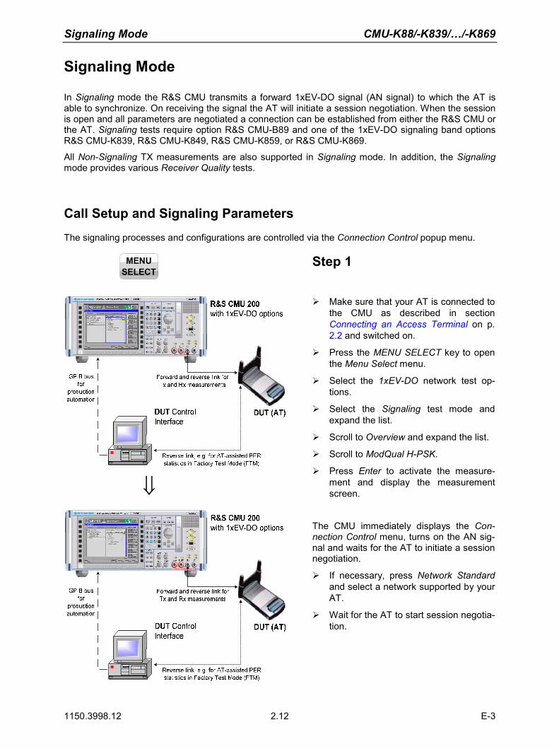
Signaling Mode CMU-K88/-K839/…/-K869
1150.3998.12 2.12 E-3
Signaling Mode
In Signaling mode the R&S CMU transmits a forward 1xEV-DO signal (AN signal) to which the AT is able to synchronize. On receiving the signal the AT will initiate a session negotiation. When the session is open and all parameters are negotiated a connection can be established from either the R&S CMU or the AT. Signaling tests require option R&S CMU-B89 and one of the 1xEV-DO signaling band options R&S CMU-K839, R&S CMU-K849, R&S CMU-K859, or R&S CMU-K869.
All Non-Signaling TX measurements are also supported in Signaling mode. In addition, the Signaling mode provides various Receiver Quality tests. Call Setup and Signaling Parameters
The signaling processes and configurations are controlled via the Connection Control popup menu.
MENU
SELECT
Step 1
⇓
Make sure that your AT is connected to the CMU as described in section Connecting an Access Terminal on p. 2.2 and switched on.
Press the MENU SELECT key to open the Menu Select menu.
Select the 1xEV-DO network test op-tions.
Select the Signaling test mode and expand the list.
Scroll to Overview and expand the list.
Scroll to ModQual H-PSK.
Press Enter to activate the measure-ment and display the measurement screen.
The CMU immediately displays the Con-nection Control menu, turns on the AN sig-nal and waits for the AT to initiate a session negotiation.
If necessary, press Network Standard and select a network supported by your AT.
Wait for the AT to start session negotia-tion.

CMU-K88/-K839/…/-K869 Signaling Mode
1150.3998.12 2.13 E-3
Additional Information... Alternative Settings and Measurements
... on Step 1
Signaling Measurements
Since Signaling measurements require a connection to the AT, the R&S CMU immediately displays the Connection Control screen if a connection is not yet established. The forward 1xEV-DO signal (AN signal) for synchronization and session negotiation is also switched on automatically. The default configuration of the forward 1xEV-DO signal is usually appropriate for session negotiation, provided that the AT is properly connected. The 1xEV-DO power of the AN Signal or the external at-tenuation, especially if the AT is connected via antenna.
Chapter 4
The immediate display of the connection control screen can be disabled by deselecting Auto Open if not connected under Connection Control Behavior in the Misc. tab of the Connection Control menu.
Connection Control menu
The Connection Control menu provides general settings that are valid for all 1xEV-DO measurements. Part of the settings can be overwritten in the individual measurement groups. The Connection tab provides fundamental settings for the test session (Application Selection, Network Standard), controls the connection, and displays the parameters of the AT. Handoff initiates a handoff to another band class. Layer selects and configures the protocols for the different layers of the 1xEV-DO high rate packet data system. AN Signal configures the forward 1xEV-DO (AN) signal of the R&S CMU. The AN signal is used for signaling and for data transfer in order to perform Receiver Quality tests. Network selects the network standard and defines how the R&S CMU will handle access probes from the AT. RF selects the RF input/output connectors of the R&S CMU and defines external input/output attenuation factors. Sync. controls the reference frequency and synchronization signal of the CMU.
Chapter 4
A second level of the Connection Control menu (accessible after pressing 1/2) provides additional settings:
• Trigger settings • Configuration of the I/Q-IF
interface • Configuration of the RF input
path (Analyzer) • Display settings (Misc.)

Signaling Mode CMU-K88/-K839/…/-K869
1150.3998.12 2.14 E-3
⇓
Step 2 After session negotiation, the Session In-formation area contains important parame-ters characterizing the access terminal.
If session negotiation fails, there may be configuration settings that don’t match the AT. See additional information on step 1.
Press Connect AT.
The R&S CMU displays Connecting AT… while initiating a connection to the AT. When the connection is established, the R&S CMU enters the RL: Connected state; the Connection Control menu is closed automatically. This can only be done if Test Applications are enabled. If the Default Packet Application is enabled, the connec-tion must be initiated from the AT.
Step 3 After the call is established, the CMU dis-plays the Overview measurement screen. This was the selection made in the Menu Select menu.
Use the Analyzer Level … AN Settings softkey on the right side to modify the analyzer and generator settings of the R&S CMU.
Use the Menus softkey to change to the other Tx or Rx measurements in Signaling mode.

CMU-K88/-K839/…/-K869 Signaling Mode
1150.3998.12 2.15 E-3
Additional Information... Alternative Settings and Measurements
... on Step 2
RL: Session Open and Connected states
In Session Open state the selected applications are as-signed to streams and all call parameters have been nego-tiated. Our example corresponds to the R&S CMU default configuration where the Default Signaling Application is as-signed to stream 0 (in accordance with the standard), the Default Test Application is assigned to stream 1. This con-figuration is appropriate for all measurements. A session can be open for a long time without any further activity.
In the Connected state the traffic channel is active and available for the applications that have previously been as-signed to a stream.
In general, part of the TX measurement results are available while the R&S CMU is in Session Open state. Receiver Quality measurements must be run in the Connected state with an active test application
Chapter 4. The AT also collects Receiver Quality statistics while it is in IDLE (RL: Session Open) state. Section Forward and Reverse Link Performance in chapter 4 describes how to obtain Receiver Quality results based on these statistics. This is true only if the Test Appli-cations are enabled.
Session Information
The Session Information table displays the essential char-acteristics of the session:
The AT Information values must be provided by the AT; they are only available after the R&S CMU has entered the Session Open state. The Streams values are determined by the CMU, and they are negotiated with the AT during ses-sion negotiation. Streams-related requests from the AT are ignored. The remaining parameters are R&S CMU settings and always available.
... on Step 3
Overview measurement
The results in the Overview measurement describe the power (AT Power), modulation accuracy (Rho, Carrier Fre-quency Error, Carrier Feedthrough, I/Q Imbalance), timing (Transmit Time Error), and off-carrier emissions (Sideband Suppr.).
This measurement corresponds to the Analyzer/Generator menu in Signaling mode; see section Analyzer/Generator Measurement on p. 2.6.
Chapter 4. The Overview measurement can be configured like the Ana-lyzer/Generator measurement using softkeys and hotkeys. Pressing the measurement con-trol softkey twice opens the Over-view Configuration menu.

Signaling Mode CMU-K88/-K839/…/-K869
1150.3998.12 2.16 E-3
Receiver Quality Measurements The Receiver Quality measurement provides a wide range of parameters that characterize the connec-tivity of the forward and reverse link. Forward and reverse link parameters are generally measured with different test applications (FTAP, RTAP). All Receiver Quality measurements must be performed in RL: Connected state.
In the following we assume that a connection has been established as described the last section; the default test application is assigned to stream 1.
Step 1
Press the Menus softkey and the Re-ceiver Quality hotkey to switch over to the Receiver Quality menu.
⇓
The Receiver Quality menu controls the receiver quality tests and displays the measurement results together with the basic settings, especially the test application con-figuration.
Press the Application softkey to display all applications of the Receiver Quality measurement group. Press Statistics Overview to select the overview applica-tion.
Press Statistics Overview – Reset Statis-tics to re-start the measurements.
All Received Packets counters are reset to zero and the calculation of the results is re-started, discarding all previous results.
⇓
Press the Application softkey again and select Ctrl. Ch. PER.
The three applications Control Channel PER, Forward Link PER, and Reverse Link Quality are displayed in one common menu. The active application is underlined. All three applications show the packet error rate (PER), the Confidence Level, and their specific measurement statistics. If a value exceeds the specified limits the output field turns red.
Press Ctrl Ch. PER and the ON/OFF key.
The Control Channel PER measurement is stopped; the state of the other measure-ments is not affected.

CMU-K88/-K839/…/-K869 Signaling Mode
1150.3998.12 2.17 E-3
Additional Information... Alternative Settings and Measurements
... on Step 1
Statistics overview results
The Statistics Overview menu gives an overview of all Re-ceiver Quality measurements and their statistics. Control Channel PER is the percentage of first synchronous control channel (CC) MAC layer packets that the access terminal received in error. Forward Link PER is the percentage of FTAP/FETAP test packets transmitted on the forward traffic channel that the AT failed to receive successfully. Reverse Link Quality is the percentage of FTAP/FETAP loopback packets from the AT that the R&S CMU failed to receive successfully. Termination Target PER is the percentage of RTAP RTC MAC packets from the AT that the R&S CMU failed to re-ceive within a definite target transmit duration (not active in the current release of the 1xEV-DO software). Forward Link Performance / Time is the data rate per unit of time (in kBit/s) of the FTAP/FETAP MAC layer packets transmitted on the forward traffic channel that the AT could receive successfully. Forward Link Performance / Slots is the data rate per transmitted slots of the FTAP/FETAP MAC layer packets transmitted on the forward traffic channel that the AT could receive successfully. Reverse Link Performance is the data rate per unit of time (in kBit/s) of the RTAP/RETAP RTC MAC packets from the AT that the R&S CMU could receive successfully.
Chapter 4
The Statistics Overview menu is also useful for retrieving IDLE state statistics; see section For-ward and Reverse Link Perform-ance.
For limit checks and confidence testing use the other Receiver Quality applications.
The results in the Statistics Over-view menu require different test application protocols, so they are never available altogether. The results in our example rely on the FTAP protocol; the invalid results (‘---‘) require an RTAP protocol; see step 2.
Statistics reset
Starting or stopping an individual Receiver Quality applica-tion resets the statistics for this application only. This en-sures that different Receiver Quality measurements can be run in parallel using independent statistics cycles. Use Re-set Statistics to clear all statistics and re-start all measure-ments including the calculation of the results in the Statistics Overview measurement.
Chapter 4
Like all TX measurements, Re-ceiver Quality tests can be per-formed in Single Shot mode (with a configurable statistics cycle) or in Continuous mode. The statis-tics cycle is defined as an integer number of packets, frames or control channel cycles, depend-ing on the application.
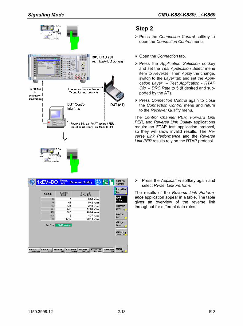
Signaling Mode CMU-K88/-K839/…/-K869
1150.3998.12 2.18 E-3
Step 2 Press the Connection Control softkey to open the Connection Control menu.
⇓
Open the Connection tab.
Press the Application Selection softkey and set the Test Application Select menu item to Reverse. Then Apply the change, switch to the Layer tab and set the Appli-cation Layer – Test Application - RTAP Cfg. – DRC Rate to 5 (if desired and sup-ported by the AT).
Press Connection Control again to close the Connection Control menu and return to the Receiver Quality menu.
The Control Channel PER, Forward Link PER, and Reverse Link Quality applications require an FTAP test application protocol, so they will show invalid results. The Re-verse Link Performance and the Reverse Link PER results rely on the RTAP protocol.
Press the Application softkey again and select Rvrse. Link Perform.
The results of the Reverse Link Perform-ance application appear in a table. The table gives an overview of the reverse link throughput for different data rates.

CMU-K88/-K839/…/-K869 Signaling Mode
1150.3998.12 2.19 E-3
Additional Information... Alternative Settings and Measurements
... on Step 1
Confidence testing
The idea behind statistical testing is to apply probability the-ory and predict a range for the PER at an early stage of the measurement. The prediction can be used to stop the measurement if the probability of the DUT to pass or fail the receiver quality test is large enough (early pass or early fail decision). Statistical testing can reduce test times consid-erably, especially if the exact PER of a receiver is very low or very high.
The Confidence Level is the statistical probability for the PER to be below the Maximum PER specified in the Limits tab of the Receiver Quality Configuration menu. In our ex-ample, the 63.59% confidence level for the Control Channel PER result is too small, i.e. the probability for the AT to pass the control channel PER test is not high enough yet so that the test must be continued. This is probably due to the rela-tively small number of control channel cycles elapsed since the start of the measurement (the duration of a control channel cycle is 426.67 ms, much longer than the test packet length).
Chapter 4
The Limits tab of the Receiver Quality Configuration menu also specifies the Min. Confidence Level for the Ctrl. Ch. PER, Fwd. Link PER, Reverse Link Quality, and Reverse Link PER applica-tions.
Moreover it is possible to stop the measurement if the Max. PER, the Min. Confidence Level, or either one of them is exceeded (Receiver Quality Configuration – Control – … – Stop Condition).
... on Step 2
Reverse Link Performance
The table in the Reverse Link Performance menu shows the reverse link throughput for all physical packet sizes that the AT used in the reverse channel. Note that the packet errors for packets with size 0 are always set to zero.
Some of the rows or columns in the table may be empty, e.g. if the selected maximum data rate on the reverse link is too small so that the AT does not use all allowed packet sizes.
For physical layer subtype 0, the throughput is given as a function of data rate. For physical layer subtype 2, the throughput is given as a function of packet size.
Chapter 4
The reverse link performance results depend on the physical layer subtype. If a layer subtype 0 or 1 is active, the rates 0, 9.6, 19.2, 38.4, 176.8 and 153.6 (kBit/s) are available. For a physical layer subtype 2, all rates except 9.6 kBit/s are available.

CMU-K88/-K839/.../-K869 Contents of Chapter 3
1150.3998.12 I-3.1 E-3
Contents
3 Manual Control .....................................................................................................3.1
Menu Structure .................................................................................................................................3.1 Test Modes ..............................................................................................................................3.1 Status Symbols ........................................................................................................................3.2
Non-Signaling Mode ......................................................................................................3.2 Signaling Mode ..............................................................................................................3.3
Configurations ..........................................................................................................................3.4 Measurement Groups ..............................................................................................................3.4
General Settings...............................................................................................................................3.6


CMU-K88/-K839/.../-K869 Manual Control
1150.3998.12 3.1 E-3
3 Manual Control
This chapter gives a brief overview of the operating concept and structure of the user interface for 1xEV-DO access terminal tests. The CMU is designed for maximum operating convenience and flexibil-ity. All instrument functions are grouped together in menus. Each menu provides configuration settings, displays a group of measured quantities, or a combination of both. Switching between the different menu groups and signaling modes is possible at any time.
In the following sections, the different measurement modes and measured quantities are discussed. Settings and measurement parameters frequently encountered are explained from a general point of view.
The formal aspects of measurement control are discussed in more detail in chapter 5 (Remote Control – Basics). For information about the CMU control elements, menu types and dialog elements within the menus refer to chapter 3 of the CMU 200/300 operating manual.
Menu Structure
The menus used to control 1xEV-DO measurements can be arranged in different ways. From a func-tional point of view, they form the following groups:
• General configurations (Connection Control)
• Measurement groups (Analyzer/Generator, Power, Modulation, Spectrum, Code Domain Power)
• Configurations specific to the measurement groups
The CMU uses main menus, popup menus, graphical measurement menus and dialog windows of vari-ous sizes. Refer to chapter 3 of the CMU 200/300 operating manual for descriptions of menus.
Test Modes
1xEV-DO measurements are performed in the test modes Non-Signaling or Signaling. The Non-Signaling mode is typically used for module tests or test of access terminals in a special "factory test mode". Non-Signaling Mode
In the Non-Signaling mode, the CMU generates an RF signal conforming to 1xEV-DO specifications and analyzes the signal transmitted by the device under test (DUT).
Signaling Mode In Signaling mode, the CMU transmits a downlink RF signal (AN Signal) to which the access terminal can synchronize. The CMU is able to configure a broad range of network parameters, to vary the settings for the different channels in its 1xEV-DO downlink signal. In addition the CMU can establish an packet switched connection for default and enhanced application tests, which provide the receiver quality measurement results.
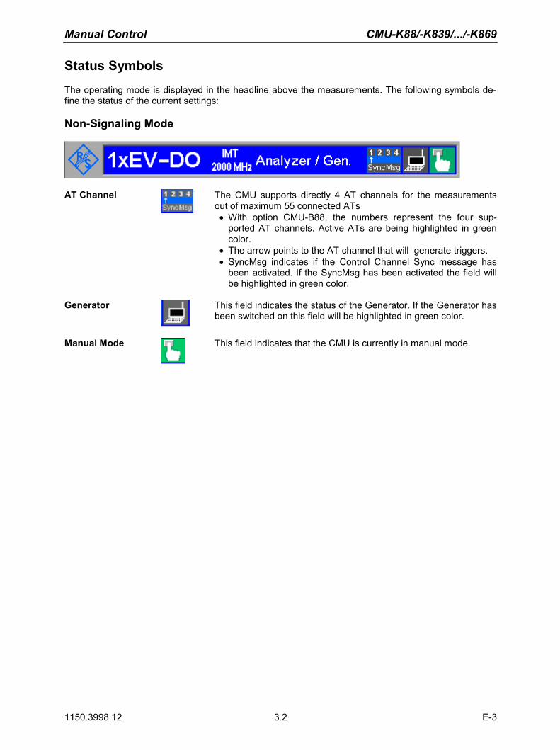
Manual Control CMU-K88/-K839/.../-K869
1150.3998.12 3.2 E-3
Status Symbols
The operating mode is displayed in the headline above the measurements. The following symbols de-fine the status of the current settings: Non-Signaling Mode
AT Channel The CMU supports directly 4 AT channels for the measurements out of maximum 55 connected ATs • With option CMU-B88, the numbers represent the four sup-
ported AT channels. Active ATs are being highlighted in green color.
• The arrow points to the AT channel that will generate triggers. • SyncMsg indicates if the Control Channel Sync message has
been activated. If the SyncMsg has been activated the field will be highlighted in green color.
Generator This field indicates the status of the Generator. If the Generator has
been switched on this field will be highlighted in green color.
Manual Mode This field indicates that the CMU is currently in manual mode.

CMU-K88/-K839/.../-K869 Manual Control
1150.3998.12 3.3 E-3
Signaling Mode
Signal / Network Icon
This icon shows a quick indication of the currently active network release (first line: Rel. 0 or A), the physical layer subtype (second line: phys. layer subtype 0 or 2) and the active application (third line: DPA / RTAP / FTAP / R&F TAP / RETAP / FETAP / R&F ETAP). If the third line (active application) is highlighted red, as shown, the selected measurement cannot work with the current connection type. For example, when a FETAP application is selected and the RLP/IP statistics measurement is active, then a red FETAP line is shown because the RLP/IP measurement requires DPA. For such cases, please verify the related measurement settings and controls.
Packet data con-nections
The connection setup for packet switched connections is shown by an analogous series of symbols. Here the icon for the Connection established (CEST) state is shown. The Signal Off (SOFF) state is indicated by this icon.
The Signal On (SON) state is indicated by this icon.
This icon indicates a Session Negotiation (NEG) in progress.
This icon indicates that a measurement is currently performed.
Manual Mode This field indicates that the CMU is currently in manual mode.
The current signaling and PPP signaling states of the CMU are shown directly below the headline. For a complete state overview, please consult figures 6-1 and 6-2 in chapter 6.

Manual Control CMU-K88/-K839/.../-K869
1150.3998.12 3.4 E-3
Configurations
The CMU offers a wide range of settings for the signal generator and analyzer, the signaling proce-dures, and the individual measurements. Configurations may apply to a whole function group (Connec-tion Control) or to a particular measurement. Connection Control The Connection Control softkey is located on the right side of the title bar of
each main and measurement menu. Depending on the mode (non-signaling or signaling), it opens a popup menu with tabs configuring the following:
• The signal generators and analyzers of the instrument (Analyzer and Gen-erator)
• The CMU receiver settings and input path configuration (included in Ana-lyzer, MS Signal)
• The trigger settings (included in Analyzer, MS Signal) • The RF connectors to be used and the external attenuation (RF In-
put/Output) • The reference signal and the system clock (Sync.)
All settings made in the Connection Control menu apply to the whole function group. Many of them are suspended, however, by measurement-specific pa-rameters while a measurement is active (see section Measurement Environment in chapter 4).
Configurations of measurements
A popup menu offering specific settings is assigned to each measurement group (Power, Modulation, Code Domain Power, and Receiver Quality). The following parameters can be defined for many measurements:
• The repetition mode, the stop condition, the statistic count and the display mode for the measurement (Control)
• Tolerances for the measured quantities (Limits, Limit Lines)
These settings are explained in more detail section
General Settings on page 3.6).
Configuration via hotkeys
The softkeys and associated hotkeys in the graphical measurement menus pro-vide the most important configurations for the current measurement (refer to chapters 3 and 4 of the CMU Operating manual). Settings made via hotkeys supersede the corresponding settings found in the measurement configuration menu.
Measurement Groups
Measurement results are indicated in two different ways: • Discrete values and parameters are displayed in output fields, lists and tables. In remote control,
these results are referred to as scalars. • Measurement curves (traces) are displayed in a Cartesian coordinate system, the time forming the
x-axis scale. Relatively small sets of test points are generally viewed in a bar graph. In remote con-trol, results of this type are referred to as arrays.
While the measurement is running in repetition mode continuous (see page 3.6), the indicated results are constantly updated. As shown in the table below, some of the measurement groups are different for the two test modes.

CMU-K88/-K839/.../-K869 Manual Control
1150.3998.12 3.5 E-3
Table 3-1 Measurement Groups of 1xEV-DO in Signaling and Non-Signaling Mode
Non-Signaling Signaling
Analyzer/Generator
Shows the settings for the signals generated and analyzed by the instrument and presents an overview of the basic scalar power and modulation results.
n/a
Power
The Narrow Band Power is measured in dif-ferent statistic modes.
Power
Narrow Band Power measurements are per-formed analogous to the non-signaling meas-urement group.
Modulation
Shows the error vector magnitude, magnitude error and phase error of the transmitted wave-form interval as a function of time. The carrier feedthrough, I/Q imbalance, frequency error, transmission time error, waveform quality and MS power error are displayed.
The I/Q Analyzer shows the I- and Q-parts of the signal in various diagrams to visualize the quality of the incoming signal.
Modulation
Modulation measurements are performed analogous to the non-signaling measurement group.
Spectrum
Shows the ACP Spectrum for 4 different fre-quency offsets in a bar diagram.
Spectrum
Spectrum measurements are performed analo-gous to the non-signaling measurement group.
Code Domain Power
The CMU measures the power of the access terminal channels.
Code Domain Power
Code Domain Power measurements are per-formed analogous to the non-signaling meas-urement group.
n/a Receiver Quality
The Receiver Quality measurements provide a wide range of parameters that characterize the connectivity of the forward and reverse link. The measurements are divided into several applica-tions, each of which provides a specific set of measurement results.
Control Channel Packet Error Rates (PER), For-ward and Reverse Link PER, Reverse Link Quality, Termination Target PER, Forward and Reverse Link Performance over time and over slots are implemented.

Manual Control CMU-K88/-K839/.../-K869
1150.3998.12 3.6 E-3
Non-Signaling Signaling
n/a
RLP Frame & IP Statistics
The RLP Frame & IP Statistics menu displays a statistical evaluation of the data flow on the CMU. RLP Frame & IP Statistics is an applica-tion of options R&S CMU-K8x9,1xEV-DO Data Testing, and R&S CMU-K87, which can be used to monitor test scenarios using the Mobile IP protocol type.
n/a
Ping
The Ping menu configures the R&S CMU to send repeated echo requests of configurable size (pings) to the mobile. The application waits for the echo and displays the ping statistics in-cluding the possible source of connection er-rors. Option R&S CMU-K87 is required for the Ping application.
General Settings
A number of settings can be made in several of the configuration menus assigned to the measurement groups Analyzer/Generator, Power, Modulation, Spectrum and Code Domain Power. In combination, these settings define the scope of the measurement, i.e. the number of waveform intervals measured and the results displayed. The following brief overview is intended to avoid confusion of terms. Application
Applications are different measurements belonging to the same measurement group. They effectively split up a measurement group into various related sub-groups which can be configured separately.
They are selected via the Application softkey in the measurement menus.
Statistic Count / Statistics Cycle
The statistic count is equal to the integer number of evaluation periods which form one statistics cycle. An evaluation period corresponds to the duration of a waveform interval (all TX measurements). Depending on the repetition mode (see below), a measurement may extend over one or several statistics cycles.
The statistic count is set in the Control tab of the configuration popup menus assigned to each measurement group.
Repetition Mode
The repetition mode defines how many statistics cycles are measured if the measurement is not stopped by a limit failure (see stop condition On Limit Fail-ure below). Two modes are available for all measurements: Single Shot The measurement is stopped after one statistics cycle Continuous The measurement is continued until explicitly terminated by the
user; the results are periodically updated
A third repetition mode is available in remote control: Counting Repeated single shot measurement with a fixed number of sta-
tistics cycles
The repetition mode is set in the Control tab of the configuration popup-menus assigned to the individual measurement groups.

CMU-K88/-K839/.../-K869 Manual Control
1150.3998.12 3.7 E-3
Note: In contrast to other measurement settings, thee repetition modes in manual and remote control are independent and do not overwrite each other. In most measurements, the default repetition mode in manual control is Continuous (observe results over an extended period of time), the default mode in remote control is Single Shot (perform one measurement and retrieve results).
Stop Condition
For all TX measurements, two stop conditions can be selected: None The measurement is performed according to its repetition
mode, regardless of the measurement results, On Limit Failure The measurement is stopped as soon as one of the limits is
exceeded, regardless of the repetition mode set. If no limit failure occurs, it is performed according to its repetition mode.
The Stop Condition is set in the Control tab of the configuration popup-menus assigned to each measurement group.
Display Mode
In graphical measurement diagrams, the Display Mode defines which of the measured and calculated traces is displayed if the measurement extends over several waveform intervals. In general, traces are evaluated at a set of fixed, equidistant test points (samples). After n waveform intervals, n measurement results per test point have been taken. After a single shot measurement extend-ing over c waveform intervals, c measurement results per test point have been taken. Current The current waveform interval, i.e. the last result for all test
points, is displayed. Minimum At each test point, the minimum value of all waveform intervals
measured is displayed. Maximum At each test point, the maximum value of all waveform intervals
measured is displayed. Max./Min. At each test point, the extreme value of all waveform intervals
measured is displayed, i.e. the maximum or minimum, which-ever has a larger absolute value.
Average At each test point, a suitably defined average over all waveform intervals measured is displayed; see paragraph on Calculation of average quantities below.
Note the difference in the calculation of Average on one hand, Minimum, Maxi-mum and Max./Min. on the other hand, if the measurement extends over more than one statistic count (repetition mode Continuous, measurement time longer than one statistic count).
The Display Mode is set in the Control tab of the configuration popup-menus assigned to the individual measurement groups.

Manual Control CMU-K88/-K839/.../-K869
1150.3998.12 3.8 E-3
Calculation of average quantities
The Average traces in the menus are obtained as follows:
Let c be the number of waveform intervals forming one statistics cycle (one Sta-tistic Count) and assume that n waveform intervals have been measured since the start of the measurement. In calculating the Average trace, the following two situations are distinguished: n ≤ c Single shot measurement or continuous measurement during the
first statistics cycle: At each test point, Average trace no. n is calculated from Average trace no. n – 1 and Current trace no. n according to the following recurrence:
),,1()(1)1(1)( cnnCurrn
nAvgnnnAvg K=+−−
=
The Average trace represents the arithmetic mean value over all n waveform intervals measured.
n > c Continuous measurement after the first statistics cycle: At each
test point, Average trace no. n is calculated from Average trace no. n – 1 and Current trace no. n according to:
)()(1)1(1)( cnnCurrc
nAvgccnAvg >+−−
=
Scalar quantities are averaged in analogy to Average traces. The formulas hold for n = 1 where the average trace becomes equal to the current trace (statistics off).
Calculation of statistical quanti-ties
In Power and Modulation measurements the statistical functions Average, Mini-mum, Maximum and Minimum/Maximum are applied to a set of test points de-pending on two independent parameters: • The time, i.e. the abscissa values ti, i ranging from 1 to the total number of
test points comprising the trace. • The waveform interval number ranging from 1 to the number n of the current
waveform interval.
The result of the statistical operations depends on the parameter range consid-ered and – in the case of statistics functions evaluated over several parameters – on the order of evaluations. This is why the definition of statistical quantities deserves some attention and is explained in the relevant sections in chapter 4. One particular example is:
In the Modulation menu quantities such as the Frequency Error, Phase Error RMS, Phase Error Peak etc. are first calculated for the current waveform interval and entered in the Current column of the output table. The results in the Mini-mum/Maximum column correspond to the extreme value of the Current results calculated over all waveform intervals measured. The results in the Average column correspond to the average of the Current results calculated according to the prescription in paragraph Calculation of average quantities above.

CMU-K88/-K839/.../-K869 Contents of Chapter 4
1150.3998.12 I-4.1 E-3
Contents
4 Functions and their Application ........................................................................ 4-1
1xEV-DO Module Tests - Overview................................................................................................ 4-2
1xEV-DO Connection Control (Non-Signaling) ............................................................................ 4-3 Connection Control (Non-Signaling) ....................................................................................... 4-3
Network Standard (Connection Control – Standard) .................................................... 4-3 Analyzer Control (Connection Control – Analyzer)....................................................... 4-4 Connection Control – Generator................................................................................. 4-12
Generator Control (Connection Control – Generator) ................................... 4-12 Generator Control (Connection Control – Generator – IQ-Access Interface) 4-21
RF Connectors (Connection Control – RF) ................................................................ 4-22 Reference Frequency (Connection Control – Sync.).................................................. 4-25 Trigger (Connection Control – Trigger)....................................................................... 4-27 I/Q-IF Interface (Connection Control – I/Q-IF) ............................................................ 4-30
1xEV-DO Module Tests (Non-Signaling) ..................................................................................... 4-32 Analyzer/Generator Measurement........................................................................................ 4-32
Softkey Selections ...................................................................................................... 4-33 Measurement Control .................................................................................... 4-34 Common settings ........................................................................................... 4-34
Measurement Results................................................................................................. 4-35 Analyzer/Generator Configuration .............................................................................. 4-36
Analyzer/Generator Configuration – Control.................................................. 4-37 Analyzer/Generator Configuration – Limits.................................................... 4-39
1xEV-DO Tests (Signaling and Non-Signaling) .......................................................................... 4-41 Power Measurements ........................................................................................................... 4-41
Softkey Selections ...................................................................................................... 4-42 Measurement Control .................................................................................... 4-42 Common Settings .......................................................................................... 4-44
Measurement Results................................................................................................. 4-45 Power Configuration ................................................................................................... 4-47
Power Configuration – Control....................................................................... 4-47 Modulation Measurements.................................................................................................... 4-48 Modulation Parameters......................................................................................................... 4-48
Softkey Selections ...................................................................................................... 4-51 Measurement Control .................................................................................... 4-51 Common settings ........................................................................................... 4-53
Measurement Results................................................................................................. 4-53 EVM H-PSK, Magn. Err. H-PSK and Phase Err. H-PSK ............................... 4-53 Overview H-PSK ............................................................................................ 4-56 I/Q Analyzer ................................................................................................... 4-57 De-spreading Mode ....................................................................................... 4-61
Modulation Configuration............................................................................................ 4-63 Modulation Configuration – Control ............................................................... 4-63 Modulation Configuration – Limits ................................................................. 4-64
Spectrum Measurements...................................................................................................... 4-65

Contents of Chapter 4 CMU-K88/-K839/.../-K869
1150.3998.12 I-4.2 E-3
Softkey Selections ...................................................................................................... 4-66 Measurement Control .................................................................................... 4-66 Common Settings .......................................................................................... 4-66
Measurement Results................................................................................................. 4-67 Spectrum Configuration .............................................................................................. 4-69
Spectrum Configuration – Control ................................................................. 4-69 Spectrum Configuration – Limits.................................................................... 4-70
Code Domain Power Measurements.................................................................................... 4-71 Softkey Selections ...................................................................................................... 4-71
Measurement Control .................................................................................... 4-72 Common Settings .......................................................................................... 4-73
Measurement Results................................................................................................. 4-73 Code Domain Power...................................................................................... 4-74 Peak Code Domain Error Power ................................................................... 4-76 Channel Power .............................................................................................. 4-76
Code Domain Power Configuration ............................................................................ 4-78 Code Domain Power Configuration – Control................................................ 4-78 Code Domain Power Configuration – Limits.................................................. 4-81
1xEV-DO Mobile Tests (Signaling) ............................................................................................. 4-83 Receiver Quality Measurements........................................................................................... 4-83
Forward and Reverse Link Performance.................................................................... 4-83 Main Menu (Receiver Quality) .................................................................................... 4-85 Test Settings............................................................................................................... 4-87
Common Settings .......................................................................................... 4-89 Measurement Results................................................................................................. 4-90
Statistics Overview......................................................................................... 4-90 Control Channel PER, Forward Link PER, Reverse Link Quality.................. 4-92 Forward Link Performance............................................................................. 4-94 Reverse Link Performance ............................................................................ 4-95 Reverse Link PER.......................................................................................... 4-97
Measurement Configurations (Receiver Quality Configuration) ................................. 4-98 Measurement Control (Receiver Quality Configuration – Control) ................ 4-99 Measurement Limits (Receiver Quality Configuration – Limits)................... 4-101
Data Application Measurements ......................................................................................... 4-104 Main Menu – RLP Frame and IP Statistics............................................................... 4-104 Test Settings............................................................................................................. 4-105 Measurement Results – RLP Frame & IP Statistics ................................................. 4-106 Main Menu – Ping Measurement.............................................................................. 4-107 Measurement Results – Ping.................................................................................... 4-108 Ping Configuration .................................................................................................... 4-109
1xEV-DO Connection Control (Signaling)................................................................................. 4-111 Connection Control (Signaling) ........................................................................................... 4-111
Connection Settings (Connection Control – Connection)......................................... 4-113 Handoff Settings (Connection Control – Handoff) .................................................... 4-118 Layer Settings (Connection Control – Layer) ........................................................... 4-119 AN Signal (Connection Control - AN Signal) ............................................................ 4-140 Network Parameters (Connection Control – Network) ............................................. 4-144 RF Connectors (Connection Control – RF) .............................................................. 4-147
Frequency-Dependent External Attenuation................................................ 4-149 Reference Frequency (Connection Control – Sync.)................................................ 4-152

CMU-K88/-K839/.../-K869 Contents of Chapter 4
1150.3998.12 I-4.3 E-3
Trigger (Connection Control – Trigger)..................................................................... 4-156 I/Q-IF Interface (Connection Control – I/Q-IF) .......................................................... 4-158 Analyzer Control (Connection Control – Analyzer)................................................... 4-160 Miscellaneous Settings (Connection Control – Misc.) .............................................. 4-166
Marker Control............................................................................................................................. 4-168


CMU-K88/-K839/.../-K869 Connection Control (Non-Signaling)
1150.3998.12 4-1 E-3
4 Functions and their Application
This chapter explains in detail all functions for the measurement of access terminals supporting the 1xEV-DO standard. The CMU 200/300 with options K-88/K-89 supports the networks listed in table 1-1 (see chapter 1). The chapter is structured according to the provided measurements and configurations. Contrary to chapter 6, Remote Control – Commands, general measurement configurations are relegated to the end of each section.
The description of each softkey, select or input field is followed by the corresponding remote-control command(s). Similarly, the description of the commands in chapter 6 also contains the corresponding menus of the user interface.
Each menu and each panel is briefly described first and then illustrated together with its call button. The menu functions are explained according to the following scheme:
Softkey
Short function definition
Designation of select/input field
Definition of function
Further description of the function: purpose, interaction with other settings, notes...
Parameter 1 Description of parameter 1
Parameter 2 Description of parameter 2
Further description of the parameters: purpose, interaction with other settings, notes...
Remote control: Remote-control command (long form) Parameter1 | Parameter2 ...

Connection Control (Non-Signaling) CMU-K88/-K839/.../-K869
1150.3998.12 4-2 E-3
Menu Select Menu Select
1xEV-DO Module Tests - Overview
The structure of this section is mainly based on the configuration and measurement groups defined in the function group IMT-2000 Mobile Station, 1xEV-DO. The menus are described in the following order: • Common settings for the Non-Signaling measurements (Connection Control) • Non-Signaling Measurements:
Analyzer/Generator • Signaling and Non-Signaling Measurements:
Power Modulation Spectrum Code Domain Power
• Signaling Measurements: Overview Receiver Quality RLP / IP Statistics Ping
• Common settings for the Signaling measurements (Connection Control) • Marker Control
Figure 4-1 1xEV-DO applications

CMU-K88/-K839/.../-K869 Connection Control (Non-Signaling)
1150.3998.12 4-3 E-3
1xEV-DO Connection Control (Non-Signaling)
Connection Control (Non-Signaling) The Connection Control menu consists of tabs to configure the inputs and outputs of the CMU and the respective signals in the function group 1xEV-DO, define the network standard, the trigger settings and the routing of I/Q and IF signals.
The menu group is activated using the softkey Connect Control to the right of the header of the measurement menu. The individual tabs (Standard, Analyzer, Generator, RF , Sync., Trigger, I/Q-IF, Misc.) can be accessed using the hotkeys at the bottom of the screen. Network Standard (Connection Control – Standard)
The Standard tab defines which network and standard is used for testing.
Figure 4-2 Connection Control – Network Standard Network Standard
The Network Standard softkey controls a list field where the band class of the network to be tested is defined. The currently active standard is shown in the headline of the screen. Refer to table 1-1 in chapter 1 for a list of the supported 1xEV-DO networks.
Remote control: CONFigure:NETWork:STANdard

Connection Control (Non-Signaling) CMU-K88/-K839/.../-K869
1150.3998.12 4-4 E-3
Analyzer Control (Connection Control – Analyzer)
The Analyzer tab configures the RF input path by defining the analyzer level and frequency. Some remote commands and parameters are not available for the CMU-B89 signaling unit, which is clearly marked in the applicable remote control paragraphs. Remote control commands without explicit reference to a hardware option are available for both CMU-B88 and CMU-B89. Details on the hardware options CMU-B88 and CMU-B89 are available in chapter 1.
Figure 4-3 Connection Control – Analyzer Settings Default All Settings
The Default All Settings switch assigns default values to all settings in the Analyzer tab (the default values are quoted in the command description in chapter 6 of this manual).
Remote control: DEFault:RFANalyzer
Analyzer Level – RF Mode
The Analyzer Level table section sets the maximum input level that can be measured. Two alternative RF Modes for defining this value are provided: Manual Manual input of maximum input level in the RF Max. Level field Auto Automatic setting of maximum input level (autoranging)
according to the peak power (PEP) of applied signal
Remote control: [SENSe:]LEVel:MODE MANual | AUTomatic

CMU-K88/-K839/.../-K869 Connection Control (Non-Signaling)
1150.3998.12 4-5 E-3
Analyzer Level – RF Manual Max. Level
The maximum expected input level can be entered in the RF Max. Level input field. Input levels exceeding the RF Manual Max. Level overdrive the input path and cause invalid results (“– – –“).
Remote control: [SENSe:]LEVel:MAXimum <Level>
External input attenuation
The range of RF Max. Level values depends on the RF input used. If an external input attenuation is reported to the instrument to compensate for a known path loss (see section RF Connectors (Connection Control – RF) on page 4-22), all levels measured are referenced to the output of the AT and therefore shifted with respect to the actual level at the input connectors of the CMU. The level ranges for the input connectors are shifted as well.
Error messages If the RF Max. Level is too high or too low, a window with the error message "<Max_Level> is out of range. <permissible max. value> is limit." and three fields will appear: Accept The permissible max. value is accepted as RF Max. Level, Re-edit RF Max. Level is entered once again, Cancel The last valid input value is maintained.
When switching over to another input, the current value of RF Max. Level is automatically adapted, if required: • Towards lower values to the maximum value of the new input, • Towards upper values to the minimum value of the new input.
Analyzer Settings – RF Channel [<>]
RF Channel defines the base station channel number (and frequency) of the generated RF signal. The brackets contain the current bandclass of the selected network.
The default settings for the channel numbers depend on the network selected. Changing the RF Channel also changes the RF Frequency setting.
Table 1-1 in chapter 1 lists the networks and standards supported by the CMU with the 1xEV-DO options.
Remote control [SENSe:]RFANalyzer:FREQuency:UNIT [SENSe:]RFANalyzer:FREQuency <Frequency>
Frequency Offset
Frequency Offset determines a frequency offset to impair the RF analyzer signal.
Remote control [SENSe:]RFANalyzer:FOFFset <Analyzer Freq. Offset>

Connection Control (Non-Signaling) CMU-K88/-K839/.../-K869
1150.3998.12 4-6 E-3
Analyzer Settings – Meas. Subtype
The measurement subtype defines the active physical layer subtypes for the forward and reverse link measurements, where the measurement
• subtype 0 is the original (release "0") physical layer,
• subtype 1 is new (revision "A") physical layer for reverse link with no changes to forward link, and
• subtype 2 is new (revision "A") physical layer for both forward and reverse links.
Measurement subtype 1 implements the following reverse link changes:
• The enhanced Access Channel is implemented to provide higher data rates, which is achieved by decreasing the interleaved symbol repetition interval (19.2 kbps (512 bits) and 38.4 kbps (1024 bits))
• No RRI is transmitted on access channel
Measurement subtype 2 implements the following channel changes: • The Forward Link Traffic channel was enhanced with additional forward
traffic packet sizes (128, 256, 512, and 5120 bits) and a larger FCS. All packets now have a 24-bit CRC (increased from 16 bits). The channel interleaving procedure was changed to support Symbol Reordering, Matrix Interleave, and Short Sequence Repetition, and the initialization of turbo interleaver was expanded for additional packet sizes (unchanged for legacy sizes)
• For the option CMU-B89, the Control Channel packet sizes were enhanced by 128, 256, and 512 bit packets with 24-bit CRC. The 128, 256, and 512 bit control channel packet types are not supported by option CMU-B88. New rates are supported on preamble index 71 and legacy packet structure, rates, preamble/MAC indices are unchanged for backward compatibility with Rev. 0 ATs.
Remote control [SENSe]:RFANalyzer:SUBType 0 | 1 | 2

CMU-K88/-K839/.../-K869 Connection Control (Non-Signaling)
1150.3998.12 4-7 E-3
Code Channel Filter DRC (for all measure-ment subtypes)
Code Channel Filter DRC determines if the Analyzer should analyze the incoming signal based on the presence of the Data Rate Control (DRC) channel.
As the DRC, ACK, and Data code channels are not continuously present, the measurement system allows the user to specify the conditions under which the measurement is performed. If these filters are specified in such a manner that the AT never generates the specified channel configuration, no measurements will be made. On the other hand, if one (or more) filter settings are "Don’t care“, measurements will be made both when the channel is present and when it is not. This may lead to confusing and/or rapidly changing results.
The supported code channel filters for the measurement subtypes are shown in the table below:
Code Channel Filter
Meas. Subtype
0
Meas. Subtype
2 DRC ACK Data AuxPilot ACK/DSC HalfSlot
The following table shows the expected behavior depending on the settings and the real signal for measurement subtype 0.
Code Channel Setting AT
Code Channel Setting CMU
Expected Result
OFF OFF Valid result OFF DON’T CARE Valid result OFF ON No result ON OFF No result ON DON’T CARE The I/Q Analyzer will display results from two
(or more) different types of waveforms. This can cause the display to appear very confused or erratic (for example it seems to be toggling or blinking).
ON ON Valid result

Connection Control (Non-Signaling) CMU-K88/-K839/.../-K869
1150.3998.12 4-8 E-3
For measurement subtype 2, the presence of the ACK and DSC channels in the first and second half slot has to be considered accordingly when setting the HalfSlot filter. If the actual setting is unknown, it is a good idea to set all three code channels to “DON’T CARE” and analyze the result using the I/Q Analyzer measurement (I/Q Analyzer on pg. 4-57) to determine the current setting of the incoming signal.
Remote control: [SENSe:]RFANalyzer:CCFilter:DRC ON | OFF | DCARe
Code Channel Filter ACK (for measurement subtype 0)
Code Channel Filter ACK determines if the analyzer should analyze the incoming signal based on the presence of the ACK channel. As the DRC, ACK, and Data code channels are not continuously present, the measurement system allows the user to specify the conditions under which the measurement is performed. If these filters are specified in such a manner that the AT never generates the specified channel configuration, no measurements will be made. On the other hand, if one (or more) filter settings are "Don’t care“, measurements will be made both when the channel is present and when it is not. This may lead to confusing and/or rapidly changing results.
Remote control: [SENSe:]RFANalyzer:CCFilter:ACK ON | OFF | DCARe
Code Channel Filter Data (for all measure-ment subtypes)
Code Channel Filter Data determines if the analyzer should analyze the incoming signals based on the presence of the Data channel. As the DRC, ACK, and Data code channels are not continuously present, the measurement system allows the user to specify the conditions under which the measurement is performed. If these filters are specified in such a manner that the AT never generates the specified channel configuration, no measurements will be made. On the other hand, if one (or more) filter settings are "Don’t care“, measurements will be made both when the channel is present and when it is not. This may lead to confusing and/or rapidly changing results.
Remote control [SENSe:]RFANalyzer:CCFilter:DATA ON | OFF | DCARe
Code Channel Filter AuxPilot (for measurement subtype 2 only)
Code Channel Filter AuxPilot determines if the analyzer should analyze the incoming signals based on the presence of the AuxPilot channel.
Remote control [SENSe]:RFANalyzer:CCFilter:APILot ON | OFF | DCARe
Code Channel Filter ACK/DSC (for measurement subtype 2 only)
Code Channel Filter ACK/DSC determines if the analyzer should analyze the incoming signals based on the presence of the ACK / DSC channel. ACK / DSC are time-multiplexed on Walsh channel W12
32, where the DSC channel is transmitted on the second half slot on Walsh channel W12
32, and the ACK channel bit is transmitted on the first half slot on Walsh channel W12
32.
Remote control [SENSe]:RFANalyzer:CCFilter:ADSC OFF | ACK | DSC| DCARe

CMU-K88/-K839/.../-K869 Connection Control (Non-Signaling)
1150.3998.12 4-9 E-3
Code Channel Filter HalfSlotFilter
Code Channel Filter HalfSlotFilter determines which half slot(s) of the code channel is/are evaluated. The DSC channel is transmitted on the second half slot on Walsh channel W12
32, and the ACK channel bit is transmitted on the first half slot on Walsh channel W12
32. (for measure-ment subtype 2 only)
Remote control [SENSe]:RFANalyzer:CCFilter:HSLot BOTH | 1 | 2
Data Channel Modulation Type (for measurement subtype 2 only)
All data transmitted on the Reverse Traffic Channel has to be encoded, block interleaved, sequence repeated, BPSK, QPSK, or 8-PSK modulated and orthogonally spread by Walsh function W2
4 or Walsh function W12 or both. The Data
Channel is modulated as shown below:
AUTO Automatic selection of the data channel modulation type. If AUTO is set, the signal is measured and decoded irrespective of the modulation type. Signals with unrecognized modulation types are ignored. The detected modulation type can be queried using [SENSe]:RFANalyzer:DCHannel:MTYPe?
B4 BPSK modulation with 4-ary Walsh cover (W2
4)
Q4 QPSK modulation with 4-ary Walsh cover (W2
4)

Connection Control (Non-Signaling) CMU-K88/-K839/.../-K869
1150.3998.12 4-10 E-3
Q2 QPSK modulation with 2-ary Walsh cover (W12)
Q4Q2 (QPSK, W2
4) + (QPSK, W12)
QPSK Modulator
1 Symbol
1 Symbol
4 Chips
4 Chips
Demux
First 2 Code Symbols
QPSK Modulator
2 Symbols
2 Symbols
4 Chips
4 Chips
Last 4 Code Symbols
∑Data I
Data Q
)(W 42 −−++=
)(W 42 −−++=
)(W 21 −+=
)(W 21 −+=
31
32
32
31
D4I
∑
D4Q
D2I
D2Q

CMU-K88/-K839/.../-K869 Connection Control (Non-Signaling)
1150.3998.12 4-11 E-3
E4E2 (8-PSK, W24) + (8-PSK, W1
2)
8-PSK Modulator
1 Symbol
1 Symbol
4 Chips
4 Chips
Demux
First 3 Code Symbols
8-PSK Mapping
2 Symbols
2 Symbols
4 Chips
4 Chips
Last 6 Code Symbols
)(W 42 −−++=
)(W 42 −−++=
)(W 21 −+=
)(W 21 −+=
31
32
32
31
∑Data I
Data Q
E4I
∑
E4Q
E2I
E2Q
Remote control: [SENSe]:RFANalyzer:DCHannel:MTYPe:MODE AUTO | B4 | Q4 | Q2 |
Q4Q2 | E4E2 Long Code Mask I/Q
Long Code Mask determines the used I/Q-Long Code Masks for the analyzed 1xEV-DO signal. In order of the measurements to work both long code masks have to be set according to the analyzed (reverse) signal from the AT under test.
Remote control [SENSe:]RFANalyzer:LCMask:I:LSB <HexString[8chars]> [SENSe:]RFANalyzer:LCMask:I:MSB <HexString[3chars]> [SENSe:]RFANalyzer:LCMask:Q:LSB <HexString[8chars]> [SENSe:]RFANalyzer:LCMask:Q:MSB <HexString[3chars]>
Reverse Link Frame Offset AT1-4
Reverse Link Frame Offset AT1-4 specifies the frame offset timing of the reverse link signal from the specified access terminal. Since the required 1xEV-DO option CMU-B88 does not actually control the access terminal, it is the responsibility of the operator to ensure that the value established by this command matches the frame offset that is used by the access terminal. In addition, this value affects the timing of the Rev Frame Trigger for the specific user. The generator settings for DRC Lock State, DRC Lock Period and DRC Lock Length are displayed in the same line for each access terminal.
Remote control (only for option CMU-B88): [SENSe:]RFANalyzer:AT<nr>:RLINk:FROFfset <Value>|MIN|MAX|DEF

Connection Control (Non-Signaling) CMU-K88/-K839/.../-K869
1150.3998.12 4-12 E-3
Connection Control – Generator
The popup menu Generator provides the settings for: • 1xEV-DO Generator [Options CMU-B88 and CMU-B89] • I/Q-Access Interface Setup [Option CMU-B82] The generator and the I/Q-access boards can be switched alternately to ON or OFF or both to OFF. In order to switch the I/Q-access board on, the hardware option B-82 has to be installed in the CMU. Some remote commands and parameters are not available for the CMU-B89 signaling unit, which is clearly marked in the applicable remote control paragraphs. Remote control commands without explicit reference to a hardware option are available for both CMU-B88 and CMU-B89. Generator Control (Connection Control – Generator)
The Generator control tab allows the setting of all signals generated by the CMU.
Figure 4-4 Connection Control – Generator
Generator Control
The Generator Control switch indicates the operating status of the RF generator (ON or OFF). Selecting the Generator switch and the ON/OFF key switches the generator on or off. The IQ-Access Interface Control switch (see 4-21) is toggled with the Generator Control switch, since both modules cannot operate simultaneously.
Remote control: INITiate:RFGenerator ABORt:RFGenerator FETCh:RFGenerator:STATus?

CMU-K88/-K839/.../-K869 Connection Control (Non-Signaling)
1150.3998.12 4-13 E-3
Default Settings The Default Settings switch assigns default values to all settings in the Generator
tab (the default values are quoted in the command description in chapter 6 of this manual).
Remote control: DEFault:RFGenerator ON | OFF
Output Power (1xEV-DO)
Output Power sets the 1xEV-DO output power generated by the CMU
Remote control: SOURce:RFGenerator:POWer:OUTPut
Total Output Power (incl. AWGN)
Total Output Power displays the total output power generated by the CMU, including AWGN power.
Remote control: SOURce:RFGenerator:POWer:OUTPut?
RF Channel [<>] The RF Channel sets the base station channel number (and frequency) of the generated RF signal. Changing the RF channel resets the RF frequency setting and vice versa. The default settings for the channel numbers vary with the selected network, which is described in chapter 6 for the given remote control commands.
Remote control: SOURce:RFGenerator:FREQuency [:RF]:UNIT SOURce:RFGenerator:FREQuency[:RF]
PN Offset PN Offset sets the offset of the PN sequence. Changing the PN offset changes the timing of the short code spreading and the contents of the Sync message on the Control Channel.
Remote control: SOURce:RFGenerator:PROPerty:PNOFfset
Generator Mode Generator Mode sets the operating mode of the generator. Possible values are Normal and Continuous Pilot.
In Continuous Pilot mode, the 1xEV-DO generator will generate a continuous pilot signal. The pilot signal fills the entire slot and the power of the signal is determined by the Output Power setting.
During this special mode, all other commands will be accepted and processed as normal, but the pending changes to the signal will not occur until this special mode is disabled.
Remote control SOURce:RFGenerator:MODE
Signal Subtype This option selects the active physical layer signal subtypes for the RF generator as described on p. 4-161.
Remote control for installed option CMU-B89: SOURce:RFGenerator:SUBType 0 | 1 | 2

Connection Control (Non-Signaling) CMU-K88/-K839/.../-K869
1150.3998.12 4-14 E-3
Impairments -AWGN Mode
The AWGN Mode sets the AWGN power level for 1xEV-DO testing. This provides a Normal and a High Power range that can be selected with this menu item. The range of the Normal mode is identical to the original implementation (+4.0 dB to -20 dB), the range of the High Power mode is +11.7 dB to -12.0 dB.
Remote Control: SOURce:IMPairments:LEVel:AWGN:MODE[?] NORMal | HPOWer
Impairments– AWGN Level
AWGN Level turns on or off the Additive White Gaussian Noise generator and sets the level for modulation, depending on the defined AWGN Mode. This provides noise to more closely simulate actual operating conditions in the network.
Remote control SOURce:IMPairments:LEVel:AWGN <AWGN Level>
Impairments– AN Freq. Offset
AN Freq. Offset modifies the carrier frequency of the RF Generator signal. If the RF Frequency is set to a frequency which doesn’t correspond to the actual selected RF Channel, the setting of AN Freq. Offset is disabled.
Remote control: SOURce:IMPairments:FOFFset[:RF] <Freq. Offset>
Traffic – Control – Sync. Message Enable
Sync. Message Enable allows the generator to transmit a synchronization message on the control channel. The timing and type of Sync. message is specified wíth the traffic control parameters described below.
Remote control: INIT:RFGenerator:SNCMessage ABORt:RFGenerator:SNCMessage FETCh:RFGenerator:SNCMessage:STATus?
Traffic – Control – Packet Start Offset
Packet Start Offset defines when the generator should transmit the Sync. message on the control channel. The offset value is measured as the number of slots from the first slot of the control channel cycle, the range of values is 0 to 3, inclusive.
Remote control (for installed option CMU-B88): SOURce:RFGenerator:SNCMessage:PSOFfset
Traffic – Control – Data Rate
Sync. Message defines the type of synchronization message on the traffic channel. It specifies a choice between the DRC indexes 1 and 2. Each DRC index corresponds to a fixed data rate and number of slots; see Table 4-1 on page 4-17.
Remote control: SOURce:RFGenerator:SNCMessage:DRINdex SOURce:RFGenerator:SNCMessage:DRATe?
Traffic – AT1..4 – Access Terminal Enable
If option R&S CMU-B88 is available, the CMU supports the generation of data for up to 4 access terminals at the same time. Access Terminal Enable specifies the ON/OFF state of the each of the four data streams.

CMU-K88/-K839/.../-K869 Connection Control (Non-Signaling)
1150.3998.12 4-15 E-3
Remote control for installed option CMU-B88: INIT:RFGenerator:AT<nr>:MAC:INDex ABORt:RFGenerator:AT<nr>:MAC:INDex FETCh:RFGenerator:AT<nr>:MAC:INDex:STATus? Remote control for installed option CMU-B89 (only AT1 per default): INIT:RFGenerator:MAC:INDex ABORt:RFGenerator:MAC:INDex FETCh:RFGenerator:MAC:INDex:STATus?
Traffic – AT1..4 – MAC Index
MAC Index specifies the MAC index of the specified access terminal. MAC index values of 5 to 63, inclusive are permitted. With Network Revision A, the MAC index can also have the additional values 72 to 127. Each of the four access terminals must use a unique MAC index.
Please note that with installed option CMU-B89, the MAC index values can only be modified when Access Terminal Enable is set to OFF.
Remote control for installed option CMU-B88: SOURce:RFGenerator:AT<nr>:MAC:INDex Remote control for installed option CMU-B89: SOURce:RFGenerator:MAC:INDex[:REV0] SOURce:RFGenerator:MAC:INDex[:REVA]
Traffic – AT1..4 – MAC AT <nr> Level
MAC AT <nr> Level specifies the level relative to the generator output power for each of the AT channels. The range of level values is –7.0 dB to –25.0 dB, inclusive.
Remote control for installed option CMU-B88: SOURce:RFGenerator:AT<nr>:MAC:LEVel
Traffic – AT1..4 – Send Packets
Send Packets enables or disables the transmission of traffic packets to the specified access terminal. The State field can have the states OFF, ON and RUN. The Progress field shows the progress of transmission. To start the transmission of traffic packets, the Generator Control has to be ON, the AT Access Terminal Enable has to be ON, the Send Packets has to be ON. For installed option CMU-B89, the DUT Forward Packet Activity has to be above 0%. The state of the Send Packets is ON when the ability to send packets is enabled. When the packets are actually generated, the Send Packets state changes to RUN.
Remote control for installed option CMU-B88: INIT:RFGenerator:AT<nr>:PSTReam ABORt:RFGenerator:AT<nr>:PSTReam FETCh:RFGenerator:AT<nr>:PSTReam:STATus? Remote control for installed option CMU-B89: INIT:RFGenerator:PSTReam ABORt:RFGenerator:PSTReam FETCh:RFGenerator:PSTReam:STATus?
Traffic – AT1..4 – Packet Count
Packet Count specifies the number of packets to be sent to the specified access terminal. If “infinite” is selected a continuous stream of packets is sent.

Connection Control (Non-Signaling) CMU-K88/-K839/.../-K869
1150.3998.12 4-16 E-3
Remote control for installed option CMU-B88: SOURce:RFGenerator:AT<nr>:PCOunt Remote control for installed option CMU-B89: SOURce:RFGenerator:PCOunt
Traffic – AT1..4 – Packet Start Offset
Packet Start Offset specifies the amount of time (in slots) from the end of the last packet (sent to the specified access terminal) to the start of the next packet (sent to the specified access terminal). Values of 0 to 255, inclusive are permitted. For single slot packets, a value of zero will cause the next packet to be sent in the immediate next slot. For multiple slot packets, a value of zero will cause the next packet transmission to start three slots after the end of the previous packet. The three slot delay is identical to the interleaving delay between slots for multiple slot packets. The offset value is attached to the end of the preceding packet. Therefore, an offset value of zero with a rate change from a single slot packet to a multiple slot packet will cause the first slot of the multiple slot packet to be transmitted in the slot immediately following the single slot packet.
Remote control (only for installed option CMU-B88): SOURce:RFGenerator:AT<nr>:PSOFfset
Traffic – AT1..4 – Interleaving Factor
The Interleaving Factor allows an increase of the rate of data packets sent to a specific user (access terminal AT 1 to 4). With the default setting 1, each of the four ATs receives one fourth of the packets. Selecting an interleaving factor 2, 3, or 4 for a particular AT doubles, triples, or quadruples the rate of data packets addressed to this AT; the residual packet rate is distributed among the other ATs. With interleaving factor 4, all packets are addressed to a single AT; which accelerates the AT-assisted packet error rate measurement.
Remote control (only for installed option CMU-B88): SOURce:RFGenerator:AT<nr>:IFACtor

CMU-K88/-K839/.../-K869 Connection Control (Non-Signaling)
1150.3998.12 4-17 E-3
Traffic – AT1..4 – Data – Rate
Rate specifies the DRC index of the forward traffic for a specific access terminal. The data rate and the number of slots within the packet are specified by the DRC index, as described in the following table:
Table 4-1: Assignment between DRC index, data rates and no. of slots Index Rate [kBit/s] #Slots
1 38.4 16 2 76.8 8 3 153.6 4 4 307.2 2 5 307.2 4 6 614.4 1 7 614.4 2 8 921.6 2 9 1228.8 1
10 1228.8 2 11 1843.2 1 12 2457.6 1
For signal subtype 2, the assignment of the packet type index, which defines an unambiguous assignment of the data rate, packet size, and the slot count can be found in chapter 6 with the SOURce:RFGenerator:PTINdex description.
Remote control for installed option CMU-B88: SOURce:RFGenerator:AT<nr>:DRINdex*) SOURce:RFGenerator:AT<nr>:PTINdex SOURce:RFGenerator:AT<nr>:DRATe? SOURce:RFGenerator:AT<nr>:SCOunt? Remote control for installed option CMU-B89: SOURce:RFGenerator:DRINdex*) SOURce:RFGenerator:PTINdex SOURce:RFGenerator:PSIZe? SOURce:RFGenerator:DRATe? SOURce:RFGenerator:SCOunt? *) Please note that these commands are only queries when the signal subtype is set to 2. For signal subtype 2, use SOURce:RFGenerator:AT<nr>:PTINdex with CMU-B88 or SOURce:RFGenerator:PTINdex with CMU-B89.
Traffic – AT1..4 – Data - Pattern
Pattern specifies a data pattern to be used within the forward link packets addressed to a specific access terminal. The data consists of 32 bits, or 4 bytes, expressed as an 8-digit hex number. This pattern is repeated within the packet. The most significant bit is the first bit within the packet.
Remote control for installed option CMU-B88: SOURce:RFGenerator:AT<nr>:PATTern Remote control for installed option CMU-B89: SOURce:RFGenerator:PATTern

Connection Control (Non-Signaling) CMU-K88/-K839/.../-K869
1150.3998.12 4-18 E-3
Traffic – AT1..4 – Power Control – Power Ctrl. Bits
Power Control Bits define how the power control bits are sent from the CMU to the specified access terminal. The power control bits control the access terminal total output power (when the access terminal is using closed loop power control).
Range Test The CMU sends a sequence of up power bits followed by a
sequence of down power bits. The number of bits up and down is configurable.
All Up The CMU sends only up power control bits.
All Down The CMU sends only down power control bits. This may cause the access terminal power level to decrease to a level too low for measurements to be made.
Hold The CMU sends alternating up/down power control bits.
Pattern A user defined pattern of power control bits will be sent by the CMU. This pattern is divided in 4 areas of power control bits which are described in the following Pattern parameters below. For each area a user defined number of Up or Down bits can be defined and sent by the CMU.
External (AUX3/4 – Pin 6)
The state of Pin 6 of the CMU AUX3/4 connector is sampled at the start of the slot and used as the power control bit (only for installed option CMU-B88).
Remote control for installed option CMU-B88:
SOURce:RFGenerator:AT<nr>:PCBits Remote control for installed option CMU-B89: SOURce:RFGenerator:PCBits
Traffic – AT1..4 – Power Control – Range Test Count
Range Test Count sets the number of power control bits to be used to perform the Range test. E.g. a value of 100 means that 100 UP bits are sent followed by 100 DOWN bits.
Remote control (only with option CMU-B88): SOURce:RFGenerator:AT<nr>:PCBits:RTES:NOBits
Traffic – AT1..4 – Power Control – Pattern – Inject Pattern
Inject Pattern starts the injection of a power control bit pattern into the power control bit stream. The configuration of the pattern is defined by the configuration fields below. This is the same pattern as may be selected by the pattern mode described above. After activation, the button Inject Pattern remains disabled until the complete pattern has been sent. Only then can another pattern be sent. The injection of the pattern starts only at the end of the current power control sequence.
Remote control (only with option CMU-B88): PROCedure:RFGenerator:AT<nr>:PCBits:PATTern <InjectStatus>

CMU-K88/-K839/.../-K869 Connection Control (Non-Signaling)
1150.3998.12 4-19 E-3
Traffic – AT1..4 – Power Control – Pattern – Area 1..4 – Number of Bits
Number of Bits defines the number of bits in the area of the user defined pattern for a specific access terminal.
Remote control (only with option CMU-B88): SOURce:RFGenerator:AT<nr>:PCBits:PATTern:AREA<nr>:NOBits
Traffic – AT1..4 – Power Control – Pattern – Area 1..4 – Polarity
Polarity defines the orientation of all power control bits in this area of the pattern for a specific access terminal. Possible values are Up or Down.
Remote control (only with option CMU-B88): SOURce:RFGenerator:AT<nr>:PCBits:PATTern:AREA<nr>:POLarity
Traffic – AT1..4 – DRCLock – DRCLock State
The state of the DRCLock indicates to the access terminal the ability of the base station to receive its DRC channel. If the DRCLOCK state is 0, the access terminal will not request data from base station. Possible values are 0 and 1. The default value is 0. In the same line the current analyzer settings for the Reverse Link Frame Offset are displayed.
Remote control (only with option CMU-B88): SOURce:RFGenerator:AT<nr>:DRCLock:STATe
Traffic – AT1..4 – DRCLock – DRCLock Period
DRCLock Period defines period of DRCLock bit transmissions, in terms of slots. Possible values for signal subtype 0 are 8 and 16. For signal subtype 2 the DRCLock Period parameter is not configurable, it is ignored for the subtype 2 physical layer user. For the subtype 2 physical layer, the DRC Lock bit is transmitted on a separate channel, as opposed to subtype 0 physical layer where it is punctured periodically in the RPC channel.
Remote control for installed option CMU-B88: SOURce:RFGenerator:AT<nr>:DRCLock:PERiod Remote control for installed option CMU-B89 (only for subtype 0): SOURce:RFGenerator:DRCLock:PERiod
Traffic – AT1..4 – DRCLock – DRCLock Length
DRCLock Length defines how often the DRCLock bit will be transmitted, before it is updated with the DRCLock state. Possible values for signal subtypes 0 and 2 are 4, 8, 16, and 32. The values are are expressed in terms of DRCLock periods.
Remote control for installed option CMU-B88: SOURce:RFGenerator:AT<nr>:DRCLock:LENGth Remote control for installed option CMU-B89: SOURce:RFGenerator:DRCLock:LENGth
Traffic – AT1..4 – H-ARQ – H-ARQ Mode
The H-ARQ is a new channel in 1xEV-DO Network Revision A. The reverse link transmission method in subtype 2 physical layer of 1xEV-DO Revision A (Rev. A) is different from Revision 0 (Rev. 0). The Rev. A reverse link packets are composed of 4 subpackets comprising 4 slots each.
The AN is allowed to terminate the transmission of the remainder of the subpackets early if it is able to correctly demodulate the packet, which effectively increases the transmission rate. This is very similar to the ARQ used on the forward link. To support the early termination, a new forward link H-ARQ MAC channel is added in

Connection Control (Non-Signaling) CMU-K88/-K839/.../-K869
1150.3998.12 4-20 E-3
Rev A. For non-signaling, where the reverse link is not demodulated, it is sufficient to configure the H-ARQ channel to send either all ACK bits or all NAK bits.
For signal subtype 0 this setting is not applicable. The possible values for signal subtype 2 are ACK and NAK.
Remote control (only with option CMU-B88): SOURce:RFGenerator:AT<nr>:HARQ:MODE
Reverse Activity – MAC RAB Level
MAC RAB Level specifies the level for the reverse activity channel relative to the generator output power. The range of level values is –7.0 dB to –25.0 dB, inclusive.
Remote control (only with option CMU-B88): SOURce:RFGenerator:RAB:MAC:LEVel
Reverse Activity – RAB State
RAB State sets the value for the bit within the reverse activity channel. This channel is an indicator to the access terminal from the access network to reduce the transfer rates used on the reverse link. A value of zero indicates normal network conditions, a value of 1 indicates that the access terminal may need to reduce its reverse link transfer rates. Possible values are 0 and 1.
Remote control (only with option CMU-B88): SOURce:RFGenerator:RAB:STATe
Reverse Activity – RAB Offset
RAB Offset defines the starting position of the reverse activity (RA) bit. The starting position is specified in RABLength/8 units. The RA bit starts when the equation (SystemTime mod RABLength = RABOffset) is satisfied, with SystemTime expressed in units of slots. Possible values are 0 to 7, inclusive.
For signal subtype 2, the RAB offset setting is not applicable.
Remote control (only with option CMU-B88): SOURce:RFGenerator:RAB:OFFSet
Reverse Activity – RAB Length
RAB Length defines the length (in slots) of a reverse activity (RA) bit. Possible values are 8, 16, 32 and 64.
For signal subtype 2, the RAB length setting is not applicable.
Remote control (only with option CMU-B88): SOURce:RFGenerator:RAB:LENGth
Other ATs – Count
Other ATs – Count defines the number of additional MAC indexes that are in use within the MAC. No traffic is generated for these MAC indexes, they are used only to construct a realistic MAC. For signal subtypes 0 and 1, the possible values are 1 to 55, inclusive. For the signal subtype 2 generator, the range of other ATs is doubled (supporting values up to 110).
Remote control (only with option CMU-B88): SOURce:RFGenerator:OAT:COUNt

CMU-K88/-K839/.../-K869 Connection Control (Non-Signaling)
1150.3998.12 4-21 E-3
DUT Forward Packet Activity
The DUT Forward Packet Activity indicates how much bandwidth is allocated towards the AT during the Default Test Application. If this value is set to 100% (default), it means that all Forward Traffic Packets are directed to the AT. If it is set to 0%, the AT is not scheduled at all. Possible values are 0% to 100% in steps of 1%.
Remote control (only with option CMU-B89): SOURce:RFGenerator:FPACtivity
Generator Control (Connection Control – Generator – IQ-Access Interface)
The Generator control tab – IQ-Access Interface Setup allows the setting of all the settings for the I/Q access board. This board is available as option R&S CMU-B82, for which there is a separate manual available (R&S order number 1150.0299.32).
Figure 4-5 Connection Control – IQ-Access Interface Setup
IQ-Access Interface Control
The IQ-Access Interface Control controls the I/Q-access board operation. Pressing the IQ-Access Interface Control softkey switches the I/Q-access board ON or OFF. The IQ-Access Interface Control switch is toggled with switching the Generator Control.
Remote control: INITiate:IQACcess ABORt:IQACcess FETCh:IQACcess:STATus?

Connection Control (Non-Signaling) CMU-K88/-K839/.../-K869
1150.3998.12 4-22 E-3
Default Settings The Default Settings switch assigns default values to all settings in the IQ-Access Interface Control tab (the default values are shown in the command description in chapter 6 of this manual).
Remote control: DEFault:IQACcess:CONTrol
Rx IQ Swap Rx IQ Swap allows the swap of the I/Q data paths of the receiver. This is useful if the signaling unit permutes the signals.
Remote control: CONFigure:IQACcess:RXSWap
Timing Control Timing Control sets the timing and clock polarity control over Tx I/Q data. Bits 0-2 supply timing information. If bit 3 is set to “1”, external data is clocked on the negative edge of the CHIP16 clock, if set to “0”, then the positive edge of the clock is used.
Remote control: CONFigure:IQACcess:TCONtrol
Gain Multiplier Gain Multiplier sets the gain multiplier value for Tx I/Q data supplied to the access board. Possible values are 0, 1, 2, 4, 8 and 16.
Remote control: CONFigure:IQACcess:GMULtiplier
RF Connectors (Connection Control – RF)
The RF tab configures the connectors for RF signals. This includes defining: • The RF input and output of the CMU (RF Output, RF Input). • External attenuation at the connectors (Ext. Att. Output, Ext. Att. Input).
The tab also controls the wideband peak power measurement (Wideband Power) and indicates the result.

CMU-K88/-K839/.../-K869 Connection Control (Non-Signaling)
1150.3998.12 4-23 E-3
Figure 4-6 Connection Control – RF connectors
The RF Output softkey defines which of the three connectors RF 1, RF 2 and RF 3 OUT is to be used as the RF output connector. The symbol indicates the selected RF output. Note: Input and output connectors can be arbitrarily combined. The bi-
directional connectors RF 1 and RF 2 can be selected as RF inputs and outputs at the same time. The front panel LEDs are on (lit) if the generator is switched on or the modulation test is started.
Remote control: OUTPut[:STATe] RF1 | RF2 | RF3
The Ext. Att. Output softkey defines an external attenuation (or gain, if the value is negative) at the selected RF output.
External attenuation is required if attenuation (such as a cable) is included in the test setup path, which is to be corrected by an increased signal level.
If an external attenuation is defined, the output signal level is referenced to the input of the device under test (DUT), the generator level is therefore shifted with respect to the actual level at the output connector of the CMU. The default value for the generator power and the level ranges for the RF outputs are also shifted provided that the generator can output the required power, compensating for the external attenuation or gain. Otherwise it is adapted to the level closest to the shifted default value.

Connection Control (Non-Signaling) CMU-K88/-K839/.../-K869
1150.3998.12 4-24 E-3
Attenuatorx dB
(Pnom + x) dBm Pnom dBm0
1 2 3
4 5 6
7 8 9
. -
ON / OFF ENTER
1100.0008.02
VARIATIONDATA
FUNCTION SYSTEM
CONTROL
DATA CTRLMENUSELECT HELP SETUP
mark symbE F
BM /µµVW
C
dBµ Vk/m
G/nA
mV
D1
dBdBm
UNIT...EXP/CM P CONT/HALT
RF4 IN
UNIVERSAL RADIO COMMUNICATION TESTER CMU 200.
ESCAPE
*
abc def ghi
jkl mno pqr
stu vwx yz
_ µ
AF IN AF OUTVOL
DEL
AUTO
INFO RESET
* #Ω
AUX 1 AUX 2
SPEECH
AUX 3
DATA 2
13 dBm MAX 2 W MAX 50 W MAX13 dBmMAX
RF 3 OUT RF 2 RF 1
DATA 1
INS
CLR
CMURF level: Pnom dBm Ext. Att. Output: x dB
x
2DEF
3GHI
1ABC
5 64
8ÜVW
7STU
. -0
9XYZ
S CRCL M
Remote control: [SENSe:]CORRection:LOSS:OUTPut<nr>[:MAGNitude] SOURce:CORRection:LOSS:OUTPut<nr>[:MAGNitude]
The RF Input softkey defines which of the three connectors RF 1, RF 2, or RF 4 IN is to be used as the RF input connector. The symbol indicates the selected RF input. Note: Input and output connectors can be arbitrarily combined. The bi-
directional connectors RF 1 and RF 2 can be selected as RF inputs and outputs at the same time. The front panel LEDs are on (lit) if a measurement is active.
Remote control: INPut[:STATe] RF1 | RF2 | RF4
The Ext. Att. Input softkey sets the value of the external attenuation (or gain) at the selected RF input.
Input of an external attenuation is required if, for example, external attenuator pads are used for protection of the sensitive RF inputs of the CMU or if path attenuation is included in the test setup.
If an external input attenuation is reported to the instrument, all levels measured are referenced to the output of the DUT and therefore shifted with respect to the actual level at the input connectors of the CMU. The level ranges for the input connectors are shifted as well.
Attenuatorx dB
(Pnom - x) dBm Pnom dBm0
1 2 3
4 5 6
7 8 9
. -
ON / OFF ENTER
1100.0008.02
VARIATIONDATA
FUNCTION SYSTEM
CONTROL
DATA CTRLMENUSELECT HELP SETUP
mark symbE F
BM /µµVW
C
dBµ Vk/m
G/nA
mV
D1
dBdBm
UNIT...EXP/CM P CONT/HALT
RF4 IN
UNIVERSAL RADIO COMMUNICATION TESTER CMU 200.
ESCAPE
*
abc def ghi
jkl mno pqr
stu vwx yz
_ µ
AF IN AF OUTVOL
DEL
AUTO
INFO RESET
* #Ω
AUX 1 AUX 2
SPEECH
AUX 3
DATA 2
13 dBm MAX 2 W MAX 50 W MAX13 dBmMAX
RF 3 OUT RF 2 RF 1
DATA 1
INS
CLR
CMUExt. Att. Input (set): x dBRF level (measured): Pnom dBm
x
2DEF
3GHI
1ABC
5 64
8ÜVW
7STU
. -0
9XYZ
S CRCL M
Remote control: [SENSe:]CORRection:LOSS:INPut<nr>[:MAGNitude] SOURce:CORRection:LOSS:INPut<nr>[:MAGNitude]

CMU-K88/-K839/.../-K869 Connection Control (Non-Signaling)
1150.3998.12 4-25 E-3
The Wideband Power softkey controls the wideband power measurement and indicates its status (RUN | HLT | OFF). The status can be changed after softkey selection (pressing once) by means of the ON/OFF key or the CONT/HALT key. The measurement result is in units of dBm. The analog bar to the right of the softkey shows the measured power relative to the RF Max. Level (see section RF Connectors (Connection Control – RF) on page 4-22): The display range is between RF Max. Level – 10 dB and RF Max. Level + 10 dB.
The wideband power measurement is performed at the RF frontend of the CMU and yields the peak power of the input signal inside a wide frequency range. It is most accurate in the input level range around 0 dBm (typically –10 dBm to +30 dBm on RF2). The main purpose of the wideband power measurement is to indicate whether an input signal is available and whether it is advisable to change the Max Level settings.
Remote control: INITiate:WPOWer FETCh:WPOWer:STATus? READ[:SCALar]:WPOWer? FETCh[:SCALar]:WPOWer? SAMPle[:SCALar]:WPOWer?
Reference Frequency (Connection Control – Sync.)
The popup menu Sync. defines the reference signals for synchronization. This includes: • The internal or external reference frequency • The output mode for the network-specific system clock (REF OUT 2)
Figure 4-7 Connection Control – Synchronization
The Reference Frequency softkey determines the source and the frequency of the reference signal. Two selections are available.

Connection Control (Non-Signaling) CMU-K88/-K839/.../-K869
1150.3998.12 4-26 E-3
Int. (10 MHz) The internal 10 MHz clock signal (TCXO or OCXO, CMU-B11/-B12) is used for synchronization. This signal is available at the REF OUT 1 connector at the rear of the instrument.
Ext. (at REF IN) An external reference signal is to be supplied to the REF IN connector. The frequency of the external reference signal must be entered in the input field.
The reference signal used is available at the REF OUT 1 output connector at the rear of the instrument making it available for use by other instruments.
Notes: With external synchronization selected, a warning message cycles on and
off if no synchronization has been performed e.g. because of missing or faulty input signal. At the same time, bit no. 6 (RFNL, Reference Frequency Not Locked) is set in the STATus:OPERation:CMU:SUM1:CMU1 sub-register associated to the CMU base system and the query [SENSe:]SYNChronize :FREQuency:REFerence:LOCKed? returns the value ON.
In the case of external synchronization with squarewave signals (TTL) ensure correct signal matching to avoid reflections. Otherwise, resulting overshoots may cause trigger problems at the CMU input. A possible remedy is to use a lowpass filter or an attenuator pad directly at the CMU input. Correct synchronization may be checked by comparing the signal REF OUT 1 or REF OUT 2 with the input signal.
This configuration is valid in all CMU function groups.
Remote control: The commands for the reference frequency are part of the CMU base system (see CMU 200/300 operating manual): CONFigure:SYNChronize:FREQuency:REFerence:MODE INTernal | EXTernal CONFigure:SYNChronize:FREQuency:REFerence <Frequency> [SENSe:]SYNChronize:FREQuency:REFerence:LOCKed?
The REF OUT 2 softkey configures a network-specific system clock available at the REF OUT 2 output connector at the rear of the instrument. The associated field allows selection between two settings:
OFF (other network)
The clock frequency of another active function group is made available at the REF OUT 2 connector instead of the current function group. The REF OUT 2 must be switched on in the other function group.
On (current network)
The network-specific system clock of the current function group is available at the REF OUT 2 output connector.
The clock frequency can be used to synchronize other instruments.
Remote control: SOURce:DM:CLOCk:STATe ON | OFF SOURce:DM:CLOCk:FREQuency <Frequency>

CMU-K88/-K839/.../-K869 Connection Control (Non-Signaling)
1150.3998.12 4-27 E-3
Trigger (Connection Control – Trigger)
The Trigger tab is part of the second group of tabs in the Connection Control menu. It is accessible after pressing the 1 / 2 toggle hotkey once. Pressing 1 / 2 again switches back to the first group of tabs described above.
TheTrigger tab defines the trigger condition for the measurement and the routing of output trigger signals.
Figure 4-8 Connection Control – Trigger
Default Settings The Default Settings checkbox assigns the default setting to all functions in the
Trigger tab (the default values are quoted in the command description in chapter 6 of this manual).
Remote control: DEFault:TRIGger[:SEQuence]
AT Selection Only one access terminal at a time can be supported by the trigger. AT Selection allows the choice of one of the four supported access terminals.
Remote control (only for option CMU-B88): TRIGger:SELect:AT
Input – Source Source sets the CMU 200 to use its internal signal trigger source or use an external
trigger supplied via the AUX 3 connector on the front panel.
The trigger setting affects the results of the Transmit Time Error measurement as described here.
Free Run No trigger. Timing error results are not available. Internal Timing error results are available when AT is correctly
synchronized with the CMU. An output frame trigger signal can be routed to pins 2 to 5 of AUX 3; see below.

Connection Control (Non-Signaling) CMU-K88/-K839/.../-K869
1150.3998.12 4-28 E-3
External Timing error results are possible if an external trigger signal is provided and the AT is correctly synchronized with the CMU.
RF Power Timing error results are not possible. IF Power Timing error results are not possible.
Remote control: TRIGger[:SEQuence]:SOURce
Input – External External indicates that the external trigger signal is to be applied to Pin 8 of the
AUX 3 connector. This holds for all three modulation schemes. Input – Slope Allows the setting of which edge of the trigger signal should be interpreted as the
actual trigger. The possible values are “Falling Edge” and “Rising Edge”.
Remote control: TRIGger[:SEQuence]:SLOPe
Input – RF Power – Trigger Level
Sets the RF Power level a signal burst has to reach to be interpreted as an incoming trigger. A setting too high results in no trigger at all, a setting too low does not allow the measurement to identify any trigger. In both cases the measurement results are invalid.
Remote control: TRIGger[:SEQuence]:THReshold:RFPower
Input – IF Power – Trigger Level
Sets the IF Power level a signal burst has to reach to be interpreted as an incoming trigger. A setting too high results in no trigger at all, a setting too low does not allow the measurement to identify any trigger. In both cases the measurement results are invalid.
Remote control: TRIGger[:SEQuence]:THReshold:IFPower
Output – Routing
The Routing functions select the type of periodic pulse signal (or no signal, setting NONE) to be applied to pins 2, 3, 4, and 5 of the AUX 3 connector. The output frame trigger is available if the Internal trigger source is selected and the RF generator is switched on. It consists of a high-pulse TTL signal with its rising edge at the beginning of the frames of the forward signal.
The CMU provides output trigger signals with the following periodicity:

CMU-K88/-K839/.../-K869 Connection Control (Non-Signaling)
1150.3998.12 4-29 E-3
Available for hardware option … CMU-B88 CMU-B89 None ---
PP2S 2.00 s Superframe 80.00 ms Ctrl. Channel 426.67 ms Ctrl. Slot <variable> AT Rev. Frame 26.67 ms Paging Frame 20.00 ms Sync.Frame 26.67 ms PCFRame 1.25 ms AT Fwd. Slot <variable> Slot 1.67 ms PwrCtrlPattern (Cont.) <variable> PwrCtrlPattern (Inject) <variable> Event Trigger <variable>
All signals can be selected for each of the pins 2 to 5, multiple assignments are
possible. The current AUX 3 pin assignment (including the external trigger input at pin 8) is shown in the diagram to the left of the trigger Setup table.
Remote control: TRIGger:OUTPut:PIN<nr>:SIGNal <Frame_Period>

Connection Control (Non-Signaling) CMU-K88/-K839/.../-K869
1150.3998.12 4-30 E-3
I/Q-IF Interface (Connection Control – I/Q-IF)
The I/Q-IF tab is part of the second group of tabs in the Connection Control menu. It is accessible after pressing the 1 / 2 toggle hotkey once. Pressing 1 / 2 again switches back to the first group of tabs described above.
The I/Q-IF tab configures the signal paths for I/Q and IF signals. With option CMU-B17, I/Q and IF Interfaces, I/Q and IF signals can be used in the framework of RF measurements and in many network tests. For a detailed description of rear panel connectors (for I/Q and IF input/output signals), test scenarios, and application examples refer to the CMU 200/300 operating manual.
Figure 4-9 Connection Control – I/Q-IF Default Settings The Default Settings checkbox assigns the default setting to all functions in the I/Q-
IF tab.
Remote control: IQIF:DEFault ON | OFF
I/Q-IF Selects the I/Q-IF test scenario, overwriting the current RX Path and TX Path
settings. Six different predefined test scenarios with fixed RX and TX path are provided; see Table 4-2: I/Q-IF scenarios and path settings below.
Additional scenarios may be defined by selecting any other combination of RX and TX paths. When this is done I/Q-IF is set to User-defined. The circuit diagram to the left of the Setup table shows the current RX and TX signal paths.
Remote control: CONFigure:IQIF:RXTXcombined BYP | BYIQ | XOIO | IOIO | IOXO | FPAT | UDEF

CMU-K88/-K839/.../-K869 Connection Control (Non-Signaling)
1150.3998.12 4-31 E-3
RX Path Selects the RX signal path, leaving the TX Path unchanged but adapting the I/Q-IF test scenario to the new RX/TX path combination: If the combination corresponds to a predefined scenario, then I/Q-IF is set to the predefined scenario; otherwise it is set to User-defined.
The circuit diagram to the left of the Setup table shows the current RX and TX signal paths.
Remote control: CONFigure:IQIF:RXPath BYP | BYIQ | XOIO | IOIO | IOXO | FPAT | UDEF
TX Path Selects the TX signal path, leaving the RX Path unchanged but adapting the I/Q-IF
test scenario to the new RX/TX path combination: If the combination corresponds to a predefined scenario, then I/Q-IF is set to the predefined scenario; otherwise it is set to User-defined.
The circuit diagram to the left of the Setup table shows the current RX and TX signal paths.
Remote control: CONFigure:IQIF:TXPath BYP | BYIQ | XOIO | IOIO | IOXO | FPAT | UDEF
IF Level Indicates the IF output level in the TX path relative to the maximum IF input/output
level (PEP) cited in the data sheet. The value is equal to the I/Q output level in the TX path relative to the maximum I/Q input voltage cited in the data sheet. The result is in dBFS units (dB Full Scale).
For 1xEV-DO networks, the value of the IF level is constantly -9 dBFS.
Remote control: [SENSe:]IQIF:LEVel?
Table 4-2: I/Q-IF scenarios and path settings
I/Q-IF RX Path TX Path Remark/Application (see also CMU manual)
RX/TX Bypass Bypass Bypass No I/Q or IF inputs/outputs connected Direct signal analysis and transmission with full measurement accuracy
Byp. w. I/Q-OF OUT Bypass w. I/Q-IF OUT
Bypass w. I/Q-IF OUT
No I/Q or IF inputs connected Analysis of received and transmitted signal via I/Q or IF
I/Q IN/OUT I/Q IN/OUT I/Q IN/OUT Insertion of signal to be analyzed and transmitted on I/Q level
IF IN_I/Q IN/OUT IF IN_I/Q IN/OUT IF IN_I/Q IN/OUT
Additional processing of received and transmitted signal on IF level (filters etc.) and analysis via I/Q
IF IN/OUT IF IN/OUT IF IN/OUT Insertion of signal to be analyzed and transmitted on IF level
Fading Bypass I/Q IN/OUT Direct analysis of received signal Modification (fading) of transmitted signal by means of an external fading simulator (SMIQ, ABFS)
User-defined Any combination of RX Path and TX Path not listed above
Any combination of RX and TX test cases listed above

Analyzer/Generator Measurement CMU-K88/-K839/.../-K869
1150.3998.12 4-32 E-3
1xEV-DO Module Tests (Non-Signaling)
Analyzer/Generator Measurement The Analyzer/Generator menu provides an overview over the 1xEV-DO function group, the current measurement status and the most important scalar parameters and measurement results.
The Analyzer/Generator menu is opened from the Menu Select menu (with associated key at the front of the instrument). The hotkeys associated to the Menus softkey switch over between the Analyzer/Generator menu and the remaining measurement menus of function group 1xEV-DO. In the softkey bar on the right side, the Analyzer/Generator menu provides different types of softkeys: • The measurement control softkey Mod. Qual. HPSK controls the measurement, indicates its status
(RUN | HLT | OFF) and opens the configuration menu Modulation Quality Configuration. The hotkeys associated to the measurement control softkey define the scope of the Modulation measurement.
• The other softkeys on the right side are combined with various hotkeys (e.g. the hotkeys RF Max. Level and RF Mode belong to the softkey Analyzer Level). The softkey/hotkey combinations provide test settings and switch over between different measurements.
Types of settings The purpose of the Analyzer/Generator menu is to provide quick access to the most
common Modulation measurements and to present the basic measurement results at a glance. All measurements prvovide two different types of settings: • Common settings are valid for all applications of function group 1xEV-DO.
Changing common settings in any application will have an impact on all measurements and applications of the function group. All common settings are also provided in the Connection Control menu (see p. 4-3 ff.). Examples of common settings are the RF input level and trigger settings (softkey Analyzer Level) and the configuration of the RF generator (softkey Generator).
• Specific settings are relevant for one application only, or they can be set independently for several applications. Changing specific settings in an application will not affect the other measurements and applications of the function group. No specific settings are provided in the Connection Control menu (see p. 4-3 ff.). Examples of specific settings are the Repetition mode (to be set independently for all applications providing this mode).
Measurement results
The output fields in the left half of the Analyzer/Generator menu show the current measurement results. The results depend on the selected application. They are described in detail in section Measurement Results on p. 4-35 f.
The results displayed in the Analyzer/Generator menu represent only a fraction of the modulation results that the CMU is able to acquire. A comprehensive set of test results is displayed in the Modulation measurement menus. In particular, the Modulation menus show many quantities as functions of time.

CMU-K88/-K839/.../-K869 Analyzer/Generator Measurement
1150.3998.12 4-33 E-3
Menu Select Menu Select
Figure 4-10 Measurement menu Analyzer / Generator
Softkey Selections
The Analyzer/Generator application is controlled by means of the measurement control softkey below the Connect. Control softkey and the associated hotkeys. The remaining softkeys select the application and provide application-specific settings.

Analyzer/Generator Measurement CMU-K88/-K839/.../-K869
1150.3998.12 4-34 E-3
Measurement Control
The Analyzer/Generator application is controlled by means of the measurement control softkey below the Connect. Control softkey and the associated hotkeys.
The Mod. Qual. H-PSK softkey controls this measurement and indicates its status (RUN | HLT | OFF). To change the status, press the Modulation softkey once and then use the front panel keys ON/OFF or CONT/HALT.
Pressing the Mod. Qual. H-PSK softkey twice (once if already selected) opens the Modulation Configuration popup menu (see section Analyzer/Generator Configuration on p. 4-36 ff.).
Remote Control: INITiate:MODulation:OVERview:HPSK ABORt:MODulation:OVERview:HPSK STOP:MODulation:OVERview:HPSK CONTinue:MODulation:OVERview:HPSK FETCh[:SCALar]:MODulation:OVERview:HPSK:STATus?
Measurement configuration
Pressing the Modulation softkey twice (once if already selected) opens the Modulation Configuration popup menu (see page 4-36). Besides, the measurement control softkey provides hotkeys to define the scope of the measurement. All these settings are also provided in the configuration menu and described in more detail in section Analyzer/Generator Configuration – Control on page 4-37 ff.
Common settings
As outlined in section Analyzer/Generator on p. 4-32 ff., some of the hotkey/softkey combinations in the Analyzer/Generator menu are valid irrespective of the application. These common settings are also provided in the Connection Control menu; for a detailed description refer to p. 4-3 ff. Softkeys
• The Trigger/Analyzer Level softkey defines the trigger settings for the measurements and controls the level in the RF signal path. The settings are provided in the Trigger and Analyzer tabs of the Connection Control menu; see sections Trigger (Connection Control – Trigger) on p. 4-27 ff. and Analyzer Control (Connection Control – Analyzer) on p. 4-4 ff.
• The Analyzer Settings 1/2 softkey defines the center frequency of the RF analyzer. The settings are provided in the Analyzer tab of the Connection Control menu; see section Analyzer Control (Connection Control – Analyzer) on p. 4-4 ff.
• The Generator Level/Impairment softkey defines the levels in all physical channels of the generated forward 1xEV-DO signal and configures an additive noise signal. The settings are provided in the Generator tab of the Connection Control menu; see section Connection Control – Generator on p. 4-12 ff.
• The Generator Settings/Power Control softkey defines the frequency of the generated forward 1xEV-DO signal, its modulation and an offset of the PN sequence. The settings are provided in the Generator tab of the Connection Control menu; see section Connection Control – Generator on p. 4-12 ff.
Settings table
The Settings table in the right half of the Analyzer/Generator menu gives an overview of the measurement settings of the current application as defined by means of the softkey/hotkey combinations or in the configuration menus. It changes when a different application is selected. The roll-key scrolls and expands the Setup table.

CMU-K88/-K839/.../-K869 Analyzer/Generator Measurement
1150.3998.12 4-35 E-3
Measurement Results
The results are displayed in various output fields in the left half of the measurement menu. The display mode (Current, Min./Max. or Average) can be selected with the softkey Display Mode which is visible when the Measurement Control softkey has been selected. Display mode Output fields
Figure 4-11 Display of results (Analyzer/Generator)
Filter settings for power measurements
The CMU measures and displays different power results, acquired with different measurement methods.
Most of the power measurements are performed using a bandwidth of 4 MHz. In particular, this holds for AT Power displayed in the Analyzer/Generator menu. The power results listed in the table below are obtained with different measurement filters.
Table 4-3: Filter settings for power measurements
Value Menu Filter
AT Power Analyzer/Generator, see below. 4 MHz bandwidth filter
Sideband Suppression Analyzer/Generator, see below. 30 kHz (Gaussian) spectrum analyzer filter
Wideband Power Connection Control, RF (see p. 4-25)
Wideband measurement
AT Power AT Power is the total transmitted power level from the access termnal. The AT
power is measured at the analyzer frequency (RF Frequency, typically set to the carrier frequency) using the receiver filter specified in standard TIA/EIA/IS-856-2.
In addition to the AT Power, the CMU measures the power at an offset frequency from the carrier; see Sideband Suppression below.

Analyzer/Generator Measurement CMU-K88/-K839/.../-K869
1150.3998.12 4-36 E-3
Rho Rho is the modulation accuracy of the transmitted signal. Rho is obtained by comparing the transmitted signal to an ideal signal as defined in standard TIA-866.
Carrier Frequency Error
Carrier Frequency Error is the difference between the nominal frequency of the selected channel and the measured frequency.
Transmit Time Error
Transmission Time Error is the time offset between the access terminal signal and the CMU signal.
Carrier Feedthrough
Carrier Feedthrough refers to the origin offset, which is the magnitude of the RF carrier relative to the magnitude of the modulated carrier.
I/Q Imbalance I/Q Imbalance is the amplitude ratio between the in-phase (I) and quadrature (Q) components of the signal.
Sideband Suppression
Sideband Suppression is a power measurement at a user–configurable offset frequency used for spurious measurements. In contrast to the AT Power the sideband suppression is measured with a 30 kHz (Gaussian) spectrum analyzer filter. The frequency offset is set via the Side Band Freq. Offset hotkey associated to the measurement control softkey. Lower Sideband Suppr. Ratio of the sideband power at RF Frequency – Side
Band Freq. Offset to the AT Power in dB Upper Sideband Suppr. Ratio of the sideband power at RF Frequency + Side
Band Freq. Offset to the AT Power in dB Note: In remote control the lower and upper sideband suppression can be
measured at up to 4 different frequencies; see keywords ...ACP1 to ...ACP4.
Statistic Count Number of waveform intervals per statistics cycle. The colored bar indicates the relative measurement progress in the statistics cycle.
Out of Tolerance Out of Tolerance is the percentage of waveform intervals that exceed the defined limits.
Remote control: READ[:SCALar]:MODulation:MQUality:HPSK? FETCh[:SCALar]:MODulation:MQUality:HPSK? SAMPle[:SCALar]:MODulation:MQUality:HPSK?
Analyzer/Generator Configuration
The popup menu Modulation Configuration contains two tabs to determine the parameters controlling the Modulation measurement including the error tolerances.
The popup menu Modulation Configuration is activated by pressing the measurement control softkey at the top right in the graphical measurement menu Modulation twice. It is possible to change between the tabs by pressing the associated hotkeys.

CMU-K88/-K839/.../-K869 Analyzer/Generator Measurement
1150.3998.12 4-37 E-3
Analyzer/Generator Configuration – Control
The Control tab controls the Modulation measurement by determining • The Repetition mode • The Stop Condition for the measurement • The number of waveform intervals/evaluation periods forming a statistics cycle (Statistic Count) • The type of result displayed (Display Mode) • The frequency offset used for the sideband suppress power measurement (Sideband Freq. Offset)
Figure 4-12 Modulation Configuration – Control
Default Settings The Default All Settings switch assigns default values to all settings in the Control
tab (the default values are quoted in the command description in chapter 6 of this manual). In addition, default switches for the individual applications are provided.
Remote control: DEFault:MODulation:MQUality:HPSK:CONTrol ON | OFF
Repetition The Repetition parameter defines how often the measurement is repeated:
Single Shot Single-shot measurement: the measurement is stopped after a statistics cycle (or after a stop condition is met, see below). A stopped measurement is indicated by the status display HLT in the Modulation softkey.
Unless otherwise stated, a statistics cycle corresponds to the number of waveform intervals/evaluation periods set under Statistic Count.
Continuous Continuous measurement: The CMU continues the measurement until it is terminated explicitly (or until the stop condition for the measurement is met, see below). The measurement results are valid after one statistics cycle; however, the measurement is continued, and the output is continuously updated. An ongoing measurement is indicated by the status display RUN in the softkey Mod.Qual.HPSK.
Single shot should be selected if only a single measurement result is required under fixed conditions. The continuous measurement is suitable for monitoring the

Analyzer/Generator Measurement CMU-K88/-K839/.../-K869
1150.3998.12 4-38 E-3
evolution of a measured quantity in time, for example for adjustments. Note: In remote mode, the counting Measurement (counting mode) is available
as a further measurement mode with a defined number of measurement cycles to be performed, see chapter 6 of this manual. The Stop Condition setting can affect the Single Shot and Continuous repetition modes.
Remote control: CONFigure:MODulation:MQUality:HPSK:CONTrol CONTinuous | SINGleshot | 1 ... 10000,<StopCondition>, <Stepmode> etc.
Stop Condition The Stop Condition field defines a stop condition for the measurement:
NONE Continue measurement irrespective of the results of the limit check
On Limit Failure Stop measurement as soon as the limit check fails (one of the tolerances is exceeded)
The Stop Condition setting is valid for both the Single Shot and Continuous repetition modes.
Remote control: CONFigure:MODulation:MQUality:HPSK:CONTrol <Repetition>,SONerror | NONE, <Stepmode> etc.
Display Mode The Display Mode field defines which of the four measured and calculated
statistical measurement results is displayed. The measurement results differ in the way the waveform interval Modulation p(t) at a fixed point in time t is calculated if the measurement extends over several waveform intervals; see section Common Settings in chapter 3: Current Measured value for current waveform interval Minimum/Maximum Extreme values of a number of waveform intervals Average Average value over a number of waveform intervals
The number of waveform intervals for calculation of the statistical values Minimum/Maximum and Average – and thus the result – depends on the repetition mode set. In detail, this implies: Single shot Display of minimum/maximum and average value from the
performed statistics cycle. Continuous Display of minimum/maximum from all waveform intervals
already measured. The average value, however, is calculated according to the rule in chapter 3, section General Settings.
Remote control: no display mode set, the READ..., FETCh... and SAMPle commands retrieve all values.
Statistic Count The input field Statistic Count defines the length of the statistics cycles in waveform intervals. The settings 1 and OFF (press ON/OFF key) are equivalent. A statistics cycle determines the duration of single-shot measurements.
Remote control: CONFigure:MODulation:MQUality:HPSK:CONTrol <Statistics>, <Repetition>, <Stop Cond>, <Step Mode>

CMU-K88/-K839/.../-K869 Analyzer/Generator Measurement
1150.3998.12 4-39 E-3
Side Band Freq. Offset
The Side Band Freq. Offset input field sets the frequency offset used for the Sideband Suppression power measurement; see section Measurement Results on p. 4-35 ff. The sideband suppression is measured at the two offset frequencies symmetrical to the RF Frequency (lower and upper sideband suppression).
Remote control: In remote control up to 4 different frequency offsets can be defined so that up to 8 symmetrical sideband suppression values are available: CONFigure:MODulation:MQUality:HPSK:CONTrol:FOFFset:SBSuppress:ACP<nr>, where <nr> = 1 to 4
Analyzer/Generator Configuration – Limits
The Limits tab defines upper and lower error limits for the measured values of all three Modulation measurement applications. The limits are set independently for the display modes Current and Max./Min. on one hand, Average on the other hand; see section Analyzer/Generator Configuration – Control on p. 4-37 ff. All measured values are described in section Measurement Results on p. 4-35 ff.
Figure 4-13 Modulation Configuration – Limits
Default All Settings
The Default All Settings switch assigns default values to all parameters of the Limits tab. The default values are quoted in the command description in chapter 6 of this manual. In addition, default switches for the individual applications and statistical modes are provided.
Remote control: DEFault:MODulation:MQUality:HPSK:CMMax:LIMit ON | OFF DEFault:MODulation:MQUality:HPSK:AVERage:LIMit ON | OFF
Current & Max/Min
Current and Max/Min sets the limits for the measured values in the current waveform interval or of the extreme values of all measured waveform intervals (Min/Max).
Remote control: CONFigure:MODulation:MQUality:HPSK:CMMax:LIMit

Analyzer/Generator Measurement CMU-K88/-K839/.../-K869
1150.3998.12 4-40 E-3
Average Average sets the limits for the average value of the measured values obtained according to the averaging rules of chapter 3, section General Settings.
Remote control: CONFigure:MODulation:MQUality:HPSK:AVERage:LIMit

CMU-K88/-K839/.../-K869 Power Measurements
1150.3998.12 4-41 E-3
Menu Select Menu Select
1xEV-DO Tests (Signaling and Non-Signaling)
Power Measurements The Power menu provides access to the Narrow Band Power measurement of the 1xEV-DO function group, the current measurement status and the most important scalar parameters and measurement results.
The Power menu is opened from the Menu Select menu (with associated key at the front of the instrument). The hotkeys associated to the Menus softkey switch over between the Power menu and the remaining measurement menus of function group 1xEV-DO. In the softkey bar on the right side, the Power menu provides different types of softkeys: • The measurement control softkey NPower controls the measurement, indicates its status (RUN |
HLT | OFF) and opens the configuration menu Power Configuration. The hotkeys associated to the measurement control softkey define the scope of the Power measurement.
• The other softkeys on the right side are combined with various hotkeys (e.g. the hotkeys RF Channel and Code Channel Filter belong to the softkey Analyzer Settings). The softkey/hotkey combinations provide test settings and switch over between different measurements.
Narrow Band Power
The NPower (Narrow band power) measurement yields the average, minimum and maximum power of an RF input signal in an evaluation period of variable length plus a statistical evaluation over several periods; see section Measurement Results on p. 4.13 ff. A fixed oversampling rate of 4 is used. The measurement is performed using a bandwidth of 4 MHz and at the frequency specified in the Analyzer Settings.
Measurement results are explained for each application.

Power Measurements CMU-K88/-K839/.../-K869
1150.3998.12 4-42 E-3
Figure 4-14 Measurement Menu Power
Softkey Selections
The Power application is controlled by means of the measurement control softkey below the Connect. Control softkey and the associated hotkeys. The remaining softkeys select the application and provide application-specific settings. Measurement Control
The Power-NPower application is controlled by means of the measurement control softkey below the Connect. Control softkey and the associated hotkeys. The properties of the measurement control softkeys are analogous in all measurements; see section Analyzer/Generator Configuration – Control on p. 4-37 ff; the hotkey functions are also provided in the Control tab of the Power Configuration menu; see section Power Configuration on p. 4-47 ff. The remaining softkeys provide common settings; see section Common settings below.

CMU-K88/-K839/.../-K869 Power Measurements
1150.3998.12 4-43 E-3
The Power menu provides the the Narrow Band Power (NPower) application, which can be selected using the appropriate hotkeys.
The NPower hotkey activates the corresponding NPower softkey to invoke the narrow band power measurement.
Remote Control: INITiate:NPOWer
The NPower softkey controls the Narrow Band Power measurement and indicates its status (RUN | HLT | OFF). To change the status, press the NPower softkey once and then use the front panel keys ON/OFF or CONT/HALT.
Pressing the NPower softkey twice (once if already selected) opens the NPower Configuration popup menu (see section Power Configuration on p. 4-47 ff.).
Remote Control: INITiate:NPOWer ABORt:NPOWer STOP:NPOWer CONTinue:NPOWer FETCh[:SCALar]:NPOWer:STATus?
The repetition mode defines when the Narrow Band Power measurement will be terminated. Two modes are available for all measurements:
Single Shot The measurement is stopped after one statistic count.
Continuous The measurement is continued until explicitly terminated by the user; the results are periodically updated.
Remote Control: CONFigure:NPOWer:CONTrol:REPetition 1...10000 | CONT |
SING | DEF
The statistic count is equal to the integer number of evaluation periods which form one statistics cycle. An evaluation period corresponds to the duration of a waveform interval (all TX measurements) or a frame (measurement group NPower). Depending on the repetition mode (see above), a measurement may extend over one or several statistics cycles.
Remote Control: CONFigure:NPOWer:CONTrol:STATistics Value | MIN | MAX |
DEF
The Access Probe Pwr. hotkey activates the corresponding Access Probe Pwr. softkey to invoke the standby power and access probe power measurements.
Remote Control: INITiate:SAPPower
The Access Probe Pwr. softkey controls the standby and access probe power measurement and indicates its status (RUN | HLT | OFF). The status can be changed after softkey selection (pressing once) by means of the ON/OFF key or the CONT/HALT key. The measurement result is in units of dBm. The Standby

Power Measurements CMU-K88/-K839/.../-K869
1150.3998.12 4-44 E-3
Power and Access Probe Power fields are blank until the mobile station registers.
Remote Control: INITiate:SAPPower FETCh:SAPPower:STATus?
Measurement configuration
The measurement control softkey also provides hotkeys to define the scope of the measurement. All these settings are also provided in the configuration menu and described in more detail in section Analyzer/Generator Configuration – Control on page 4-37 ff.
Common Settings
As outlined in section Analyzer/Generator on p. 4-32 ff., some of the hotkey/softkey combinations in the Analyzer/Generator menu are valid irrespective of the application. These common settings are also provided in the Connection Control menu; for a detailed description refer to p. 4-3 ff. Softkeys
• The Trigger/Analyzer Level softkey defines the trigger settings for the measurements and controls the level in the RF signal path. The settings are provided in the Trigger and Analyzer tabs of the Connection Control menu; see sections Trigger (Connection Control – Trigger) on p. 4-27 ff. and Analyzer Control (Connection Control – Analyzer) on p. 4-4 ff.
• The Analyzer Settings softkey defines the center frequency of the RF analyzer. The settings are provided in the Analyzer tab of the Connection Control menu; see section Analyzer Control (Connection Control – Analyzer) on p. 4-4 ff.
• The AN Signal Level/Impairment softkey defines the levels in all physical channels of the generated forward 1xEV-DO signal and configures an additive noise signal. The settings are provided in the Generator tab of the Connection Control menu; see section Connection Control – Generator on p. 4-12 ff.
• The AN Setting/Power Control softkey defines the frequency of the generated forward 1xEV-DO signal, its modulation and an offset of the PN sequence. The settings are provided in the Generator tab of the Connection Control menu; see section Connection Control – Generator on p. 4-12 ff.

CMU-K88/-K839/.../-K869 Power Measurements
1150.3998.12 4-45 E-3
Measurement Results (NPOWer)
The results are displayed in several groups of output fields in the left half of the measurement menu. The statistical evaluation is based on a basic evaluation period which is given by the Capture Buffer Size and a fixed oversampling factor of 4 and on the statistics cycle (Statistic Count) defined in the configuration menu (see section Power Configuration on p. 4-47 et.seq.; for a general description of statistical evaluations in the CMU refer to chapter 3, section General Settings).The result fields are grouped in two statistic types (Current or Average) which are themselves divided in three types of results (Average, Minimum and Maximum). Display mode Output fields
Figure 4-15 Display of results (NPower)
Filter settings for power measurements
The CMU measures and displays different power results, acquired with different measurement methods.
Most of the power measurements are performed using a bandwidth of 4 MHz. In particular, this holds for AT Power displayed in the Analyzer/Generator menu. The power results listed in the table below are obtained with different measurement filters.
Table 4-4 Filter settings for power measurements
Value Menu Filter
AT Power Analyzer/Generator, see below. 4 MHz bandwidth filter
Power (Current ) The Narrow Band Power is measured over a given capture buffer which by
default has a size of 4096 measurement shots.
- Average The Average is calculated on the base of the shots in this capture buffer.
- Minimum The Minimum Power value shot in the capture buffer.
- Maximum The Maximum Power value shot in the capture buffer.
Power (Statistic) Statistic uses the Statistic Count to calculate the average over several capture buffers, e.g. with a Statistic Count of 100 the average is built over 409600 shots.
- Average This is the average of all the shots made in the Statistic Count period.

Power Measurements CMU-K88/-K839/.../-K869
1150.3998.12 4-46 E-3
- Minimum The absolute minimum measured power over all the measurement shots in Statistic Count.
- Maximum The absolute maximum measured power over all the measurement shots in Statistic Count.
Statistic Count Number of waveform intervals (evaluation periods) per statistics cycle. The colored bar indicates the relative measurement progress in the statistics cycle.
Remote control: READ[:SCALar]:NPOWer? FETCh[:SCALar]:NPOWer? SAMPle[:SCALar]:NPOWer?
Measurement Results (SAPPower)
Output fields
Figure 4-16 Display of results (Standby and Access Probe Power)
Standby Standby Power is the power of the mobile station while it is not transmitting. The
Standby Power is measured using a 1 MHz filter (see also standard IA-866-A, section 4.3.6.3).
Access Probe Power of the mobile station access probes. A mobile station transmits access probes to begin session negotiation and when the mobile initiates a call. The Access Probe Power is measured using the receiver filter specified in standard TIA-866-A, section 5.5, with mean output power in 1.23 MHz bandwidth.
Remote control: READ[:SCALar]:SAPPower? FETCh[:SCALar]:SAPPower? SAMPle[:SCALar]:SAPPower?

CMU-K88/-K839/.../-K869 Power Measurements
1150.3998.12 4-47 E-3
Power Configuration
The tab Power Configuration contains a tab to determine the parameters controlling the Modulation measurement including the error tolerances.
The popup menu Power Configuration is activated by pressing the measurement control softkey at the top right in the graphical measurement menu NPower twice. It is possible to change between the tabs by pressing the associated hotkeys. Power Configuration – Control
The Control tab defines the scope of the measurement by determining • The Repetition mode • The Stop Condition for the measurement • The number of evaluation periods forming a statistics cycle (Statistic Count) • The number of samples per single shot Narrow Band Power measurement (Capture Buffer Size)
Figure 4-17 Power Configuration – Control
All settings may not be available for all power measurement applications. The statistical settings Repetition, Stop Condition, Statistic Count, and Display Mode have the same meaning in all measurements; they are described in section Analyzer/Generator Configuration – Control on p.4-37 ff. Note that the basic evaluation period for a single-shot narrow band power measurement is given by the number of samples defined via Capture Buffer Size. Default Settings The Default All Settings switch assigns default values to all settings in the Control
tab (the default values are quoted in the command description in chapter 6 of this manual). In addition, default switches for the individual applications are provided.
Remote Control: ---
Capture Buffer Size
Capture Buffer Size allows the user to select the buffer size for all measurement shots.
Remote Control: CONFigure:NPOWer:CONTrol:CBSize <CaptureBufferSize>

Modulation Measurements CMU-K88/-K839/.../-K869
1150.3998.12 4-48 E-3
Modulation Measurements The menu group Modulation contains several applications to measure the modulation parameters such as frequency error, waveform quality of the access terminal, and matching of the respective tolerance limits. Measurement results are displayed with a graph and a table of measurement results. The popup menu Modulation Configuration configures the parameters of the modulation measurements.
The Modulation menu is opened from the Menu Select menu (with associated key at the front of the instrument). The hotkeys associated to the Menus softkey switch over between the Analyzer/Generator menu and the remaining measurement menus of function group 1xEV-DO. • The measurement control softkey Overview H-PSK changes to EVM H-PSK etc., depending on the
application selected. This softkey controls the measurement, indicates its status (RUN | HLT | OFF) and opens the configuration menu Modulation Configuration. The hotkeys associated to the measurement control softkey define the scope of the Modulation measurement.
• The other softkeys on the right side are combined with various hotkeys (e.g. the hotkeys RF Max. Level and RF Mode belong to the softkey Analyzer Level). The softkey/hotkey combinations provide test settings and switch over between different measurements.
Modulation Parameters
The purpose of this section is to illustrate the meaning of the physical parameters determined in the Modulation measurement. For a discussion of the different averaging procedures involved please refer to chapter 3. Definition of measured quantities:
The CMU measures the H-PSK modulation accuracy by calculating the Phase Error, Magnitude Error, and Error Vector Magnitude of the modulated signal from the access terminal. Figure 4-18 shows a representation of these signal errors compared to an ideal signal.
Phase Error (PE) is the measured phase difference of the I/Q components of the signal received (from the access terminal) and an ideal reference signal at the detection points.
Magnitude Error (ME) is the normalized magnitude (amplitude) difference of the I/Q components of the signal received from the access terminal and an ideal reference signal at the detection points.
Error Vector Magnitude (EVM) is the normalized magnitude of the calculated vector linking the measured I/Q values to the ideal signal I/Q components at the detection points.
The Waveform Interval in a 1xEV-DO context is the length of a half slot, i.e. exactly 1024 chips.
The in-phase and quadrature reference components are based on an H-PSK waveform as specified in the IS-856-2 standards publication.
For a 1xEV-DO signal the composite Phase Error (PE), Magnitude Error (ME), Error Vector Magnitude (EVM), and waveform quality (Rho) are calculated.
The measurement interval for H-PSK modulation accuracy is 1024 chip intervals (≅ 0.5 ms). The graphical displays represent 1024 chips. The composite Phase Error (PE), Magnitude Error (ME), and Error Vector Magnitude (EVM) in comparison to an ideal signal is shown below:

CMU-K88/-K839/.../-K869 Modulation Parameters
1150.3998.12 4-49 E-3
Ideal QPSKsignal
Quadraturecomponent
Measuredsignal
Error vector
Magnitude error
Phase error
Q refQ
I ref IInphasecomponent
Figure 4-18 Modulation errors
The error vector is calculated as an array at each sample in the measurement interval. From the calculated error vector and the measured signal vector, the magnitude of the error vector (EVM), the phase error, and the magnitude error are calculated.
The Modulation measurement diagrams show the relative magnitude error and the relative EVM, i.e. the quantities defined above divided by the magnitude of the ideal modulation vector. In addition to the previous parameters, CMU provides the Carrier Feedthrough (origin offset), the I/Q Imbalance, and the Waveform Quality:
Q
I
Offset-correctedsignal vector
Symbol points
I/Q offset vector
Q
I
Error vector
Idealsignal vector
Symbol points:actualideal
<Q>
<I>
Figure 4-19: Modulation errors in the I/Q constellation diagram

Modulation Parameters CMU-K88/-K839/.../-K869
1150.3998.12 4-50 E-3
Carrier Feedthrough (origin offset)
Figure 4-19 is an idealized representation of the modulation errors where the effects of a pure origin offset (left diagram) and of a pure I/Q imbalance (right diagram) are completely disentangled. The I/Q offset in dB is the logarithmic ratio of the I/Q offset vector (i.e. the estimated DC-offset of the measured signal) to the average offset-corrected signal vector:
(Equation 4-1).
In equation 4-1, | Offset - corrected signal vector | RMS denotes the magnitude of the offset-corrected signal vector that is RMS-averaged over all samples.
I/Q Imbalance The I/Q imbalance in dB is equal to the difference between the estimated I and Q amplitudes of the measured signal, which are normalized and logarithmized as follows:
||
||log20 QI Q-I Imbalance I/Q><+><><><
= (Equation 4-2).
Waveform Quality
The waveform quality or Rho factor is a measure for the modulation accuracy and corresponds to the normalized correlated power between the actual waveform and the ideal waveform sampled at the constellation points. According to standard TIA-866-A, the waveform quality rOverall is defined as:
(Equation 4-3),
where where Zj,k = z[1024(j-1)+k] is the kth sample in the jth half slot of the measured signal, and Rj,k = r[1024(j-1)+k] is the corresponding sample of the ideal signal.
Modulation accuracy is measured by using the 1024N complex-valued samples, z(tk), over a time interval of N half slots. The first sample, z(t1), occurs at the first chip of a half slot and the final sample, z(t1024N), occurs at the last chip of a half slot.
For an ideal transmitter (Zj,k = Rj,k for all k), the waveform quality is equal to 1. For real transmitters, the waveform quality is a positive real number smaller than 1.

CMU-K88/-K839/.../-K869 Modulation Parameters
1150.3998.12 4-51 E-3
Menu Select Menu Select
Figure 4-20 Modulation measurement menu
Softkey Selections
Each Modulation application is controlled by means of the measurement control softkey below the Connect. Control softkey and the associated hotkeys. The remaining softkeys select the application and provide application-specific settings. Measurement Control
Each Modulation application is controlled by means of the measurement control softkey below the Connect. Control softkey and the associated hotkeys.
The Application softkey activates a set of hotkeys to select a modulation application. When an application is selected, the corresponding measurement screen is displayed.
The Overview H-PSK hotkey displays the statistics for all modulation measurements. No graphical display is provided.
Remote Control: INITiate:MODulation:MQUality:HPSK ABORt:MODulation:MQUality:HPSK STOP:MODulation:MQUality:HPSK CONTinue:MODulation:MQUality:HPSK FETCh[:SCALar]:MODulation:MQUality:HPSK:STATus?

Modulation Parameters CMU-K88/-K839/.../-K869
1150.3998.12 4-52 E-3
The Error Vector Magnitude H-PSK hotkey displays the error vector magnitude. The error vector magnitude measurement is described in section Measurement Results on p. 4-53 ff.
Remote Control: INITiate:MODulation:EVMagnitude:HPSK ABORt:MODulation:EVMagnitude:HPSK STOP:MODulation:EVMagnitude:HPSK CONTinue:MODulation:EVMagnitude:HPSK FETCh[:SCALar]:MODulation:EVMagnitude:HPSK:STATus?
The Magnitude Error H-PSK hotkey displays the magnitude error measurement. The magnitude error measurement is described in section Measurement Results on p. 4-53 ff.
Remote Control: INITiate:MODulation:MERRor:HPSK ABORt:MODulation:MERRor:HPSK STOP:MODulation:MERRor:HPSK CONTinue:MODulation:MERRor:HPSK FETCh[:SCALar]:MODulation:MERRor:HPSK:STATus?
The Phase Error H-PSK hotkey displays the phase error measurement. The phase error measurement is described in section Measurement Results on p. 4-53 ff.
Remote Control: INITiate:MODulation:PERRor:HPSK ABORt:MODulation:PERRor:HPSK STOP:MODulation:PERRor:HPSK CONTinue:MODulation:PERRor:HPSK FETCh[:SCALar]:MODulation:PERRor:HPSK:STATus?
The I/Q Analyz. hotkey displays the I/Q Analyzer measurement. The I/Q Analyzer measurement is described in section Measurement Results on p. 4-53 ff.
Remote Control: INITiate:MODulation:IQANalyzer:HPSK ABORt:MODulation:IQANalyzer:HPSK STOP:MODulation:IQANalyzer:HPSK CONTinue:MODulation:IQANalyzer:HPSK FETCh[:SCALar]:MODulation:IQANalyzer:HPSK:STATus?
Measurement configuration
Pressing the Modulation softkey twice (once if already selected) opens the Modulation Configuration popup menu (see page 4-36). Besides, the measurement control softkey provides hotkeys to define the scope of the measurement. All these settings are also provided in the configuration menu and described in more detail in section Analyzer/Generator Configuration – Control on page 4-37 ff.
The Marker softkey positions up to three markers and a baseline (D-Line) in the test diagram and shows their values. Refer to page 4-111 ff for detailed information about markers.
The softkey is only available for the following applications: EVM H-PSK, Magn. Err H-PSK and Phase Err H-PSK.

CMU-K88/-K839/.../-K869 Modulation Parameters
1150.3998.12 4-53 E-3
The Display softkey is available for the application I/Q Analyz. only. It allows the selection of the Zoom of the diagram, of the displayed Waveform Type, and the setting of the de-spreading mode of the output.
Remote Control: CONFigure:MODulation:IQANalyzer:HPSK:DESPread OFF | DATA
Common settings
As outlined in section Analyzer/Generator on p. 4-32 ff., some of the hotkey/softkey combinations in the Analyzer/Generator menu are valid regardless of the application. These common settings are also provided in the Connection Control menu; for a detailed description refer to p. 4-3 ff. Softkeys
• The Trigger/Analyzer Level softkey defines the trigger settings for the measurements and controls the level in the RF signal path. The settings are provided in the Trigger and Analyzer tabs of the Connection Control menu; see sections Trigger (Connection Control – Trigger) on p. 4-27 ff. and Analyzer Control (Connection Control – Analyzer) on p. 4-4 ff.
• The Analyzer Settings 1/2 softkey defines the center frequency of the RF analyzer. The settings are provided in the Analyzer tab of the Connection Control menu; see section Analyzer Control (Connection Control – Analyzer) on p. 4-4 ff.
• The Generator Level/Impairment softkey defines the levels in all physical channels of the generated forward 1xEV-DO signal and configures an additive noise signal. The settings are provided in the Generator tab of the Connection Control menu; see section Connection Control – Generator on p. 4-12 ff.
• The Generator Settings/Power Control softkey defines the frequency of the generated forward 1xEV-DO signal, its modulation and an offset of the PN sequence. The settings are provided in the Generator tab of the Connection Control menu; see section Connection Control – Generator on p. 4-12 ff.
Settings table
The Settings table on the right side of the Modulation menu gives an overview of the measurement settings of the current application as defined by means of the softkey/hotkey combinations or in the configuration menus. It changes when a different application is selected. The roll-key scrolls and expands the Setup table.
Measurement Results
The modulation measurement screens are similar for the applications EVM H-PSK, Magn. Err. H-PSK and Phase Err. H-PSK. The Overview H-PSK application does not provide a graph. The application I/Q Analyzer is described in section I/Q Analyzer on p. 4-57 ff. EVM H-PSK, Magn. Err. H-PSK and Phase Err. H-PSK
The description of the graphs and common output data follows below. Information specific to an application is located within the application heading. Limits for all modulation measurements are defined in the Modulation Control configuration menu.
The measurement screens can be divided into three groups:

Modulation Parameters CMU-K88/-K839/.../-K869
1150.3998.12 4-54 E-3
• Scalar measurement results (parameter lines and output tables) • Graph (a trace plotted as a function of time) • Settings overview Parameter lines 1 and 2
Measurement graph
Output table
Figure 4-21 Modulation results display
Parameter Lines Scalar measurement results and settings are indicated in the two parameter lines
above the test diagram and in the Settings table below.
1st Line The first parameter line contains the following settings:
RF Max. Level The total output power, either calculated as a function of the RF generator output level (Auto) or set manually.
DRC The settings of the DRC channel filter ACK The settings of the ACK channel filter Data The settings of the Data channel filter Ch./Freq Channel and frequency set for the BS signal
2nd Line The second parameter line contains the following marker values: Level and time of reference marker Level and time of marker 1 (setting absolute) and/or difference
from reference marker (setting relative) Level and time of marker 2 (setting absolute) and/or difference
from reference marker (setting relative)
Settings
The values shown in the Settings table are defined in the Control tab of the Connection Control menu; see section Modulation Configuration – Control on p. 4-63 ff.
Measurement Graph
The Measurement Graph is displayed as a continuous curve together with the limit lines and all active markers.
The graph in each measurement shows the respective measurement error as a function of time. The display mode for the graph (Current, Average, Max/Min) is indicated in the upper right corner of the screen.

CMU-K88/-K839/.../-K869 Modulation Parameters
1150.3998.12 4-55 E-3
Statistic Count The Statistic Count is the number of intervals since the start of the measurement. The bar graph represents a percentage of intervals measured based on the number of intervals (Statistic Count) set in the configuration menu.
Output Table The output table contains a tabular overview of modulation related measurements. The first rows of data are specific to the selected modulation measurement. The remaining rows are identical for each modulation measurement.
Three values are given for each row:
Current These are the current values of the measurement interval.
Max/Min These are the extreme values (and their polarity) of all measurement intervals since the measurement started.
Average These are the average values of a number of measurement intervals (defined by the Statistic Count setting; see section General Settings in chapter 3).
Any values exceeding the defined limits appear with a red background. Limit values are set in the Limit tab of the Modulation Configuration menu.
Modulation Error
Refer to the respective measurement type for information about the data reported in these first two rows.
Phase Error Measured phase difference of the I/Q components of the signal received (from the access terminal) and an ideal reference signal at the detection points.
Magnitude Error Difference in magnitude (in percent) between the received signal waveform and an ideal HPSK signal waveform. The magnitude error is the difference in amplitude between the measured signal from the access terminal transmitter and an ideal signal waveform at the detection points.
Error Vector Magnitude
Calculated percentage of vector error (at the detection points) between the received signal and an ideal signal.
Carrier Feedthrough
Carrier Feedthrough refers to the origin offset, which is the magnitude of the RF carrier relative to the magnitude of the modulated carrier.
I/Q Imbalance I/Q Imbalance is the amplitude ratio between the in-phase (I) and quadrature (Q) components of the signal.
Carrier Freq Error
Carrier Frequency Error is the difference between the nominal frequency of the selected channel and the measured frequency.
Transmit Time Error
Transmission Time Error is the time offset between the access terminal signal and the CMU signal.
Rho Rho is the modulation accuracy of the transmitted signal. The waveform quality is obtained by comparing the transmitted signal to an ideal HPSK signal as defined in standard TIA-866.
AT Power AT Power is the total transmitted power level from the access terminal.

Modulation Parameters CMU-K88/-K839/.../-K869
1150.3998.12 4-56 E-3
Remote Control
READ[:SCALar]:MODulation:OVERview:HPSK? FETCh[:SCALar]:MODulation:OVERview:HPSK? SAMPle[:SCALar]:MODulation:OVERview:HPSK? READ[:SCALar]:MODulation:EVMagnitude:HPSK? FETCh[:SCALar]:MODulation:EVMagnitude:HPSK? SAMPle[:SCALar]:MODulation:EVMagnitude:HPSK? READ[:SCALar]:MODulation:MERRor:HPSK? FETCh[:SCALar]:MODulation:MERRor:HPSK? SAMPle[:SCALar]:MODulation:MERRor:HPSK? READ[:SCALar]:MODulation:PERRor:HPSK? FETCh[:SCALar]:MODulation:PERRor:HPSK? SAMPle[:SCALar]:MODulation:PERRor:HPSK?
Overview H-PSK
The Overview H-PSK application allows you to view all modulation measurements in a single output table (no graph of the measurements is provided).
The peak and the RMS values of the current measurement interval are displayed for each modulation application. The average values (positive or negative) are calculated over a user definable number of Statistic Counts. The Min/Max. values are the extreme values from the start of the measurement.
Figure 4-22 Overview display

CMU-K88/-K839/.../-K869 Modulation Parameters
1150.3998.12 4-57 E-3
I/Q Analyzer
The I/Q Analyzer application displays I/Q diagrams to visualize the quality of the received measurements results. The benefit of this measurement is to easily identify issues with the received signals. To achieve this, the application I/Q-Analyzer can display the measurement results in 5 different diagrams:
• Constellation Diagram • Vector Diagram • I Phase Diagram • Q Phase Diagram • I Phase & Q Phase Diagram
Constellation Diagram and Vector Diagram contain additional scalar information of the current measurement. The settings of the Code Channel Filters (section Analyzer Control (Connection Control – Analyzer) on p. 4-4) have a major influence on evaluation and display of the measurement results. Constellation Diagram
Figure 4-23 Waveform Type Constellation

Modulation Parameters CMU-K88/-K839/.../-K869
1150.3998.12 4-58 E-3
Vector Diagram
Figure 4-24 Waveform Type Vector Diagram
I Phase Diagram
Figure 4-25 Waveform Type I Phase

CMU-K88/-K839/.../-K869 Modulation Parameters
1150.3998.12 4-59 E-3
Q Phase Diagram
Figure 4-26 Waveform Type Q Phase
I Phase & Q Phase Diagram
Figure 4-27 Waveform Type I Phase & Q Phase
Diagram Depending on the setting of Waveform Type, the different diagrams of the I/Q
Analyzer are being displayed. The following diagrams can be displayed: Constellation Diagram In the Constellation diagram the modulation vector is
only traced at the constellation points; the diagram shows a dot for each chip symbol. The constellation diagram of an ideal QPSK-modulated signal contains 4 constellation points with distance 1 from the origin and relative angles of π/2. Large variations of the symbol point positions in the constellation diagram indicate a poor signal quality; see Figure 4-23 on p. 4-57. In the QPSK application the symbol mapping between the logic data and the constellation points is

Modulation Parameters CMU-K88/-K839/.../-K869
1150.3998.12 4-60 E-3
not evaluated. As a consequence the overall phase of the diagram is random; a logic symbol may correspond to any of the four constellation points. By the symmetry, the position of the measurement shots and their sharpness the quality of the current signal can be analyzed.
Vector Diagram In the Vector diagram the modulation vector is traced with an oversampling factor of 4; the diagram shows a continuous curve. The vector diagram shows that the modulation scheme allows transitions between each pair of constellation points.
I Phase, Q Phase, I Phase & Q Phase
The I Phase, the Q Phase, and the I Phase & Q Phase diagrams trace the normalized I and Q amplitudes as a function of time. Diagrams of this type are often referred to as "eye" diagrams. The horizontal axis covers a fixed 2-chip time interval, starting at the time of a constellation point, whereas the total duration of a single shot measurement is given by the Measurement Length. The measurement curve restarts at the left diagram edge after each 2-chip period so that the complete diagram for a measurement length of 640 chips (2560 chips) contains 320 (1280) superimposed curves. The number of nodes on the vertical axis of the I or Q eye diagram is equal to the number of different I or Q amplitudes in the constellation diagram. The number of eyes is equal to the number of nodes minus one. Smeared-out nodes and small eye apertures indicate a poor signal quality. The I Phase and Q Phase diagrams are analogous; the combined I Phase & Q Phase diagram displays the I Phase diagram on top of the Q Phase diagram. To customize the graphical representation it is possible to zoom the diagrams in vertical direction, keeping the zero-amplitude reference at fixed position, and to display or remove the grid.
Output Table The output table in the diagram types Constellation and Vector display the following results:
AT Power AT Power is the total transmitted power level from the access terminal.
Rho Rho is the modulation accuracy of the transmitted signal. The waveform quality is obtained by comparing the transmitted signal to an ideal HPSK signal as defined in standard TIA-866.
Carrier Feedthrough
Carrier Feedthrough refers to the origin offset, which is the magnitude of the RF carrier relative to the magnitude of the modulated carrier.
I/Q Imbalance The I/Q Imbalance is the amplitude ratio between the in-phase (I) and quadrature (Q) components of the signal.

CMU-K88/-K839/.../-K869 Modulation Parameters
1150.3998.12 4-61 E-3
Error Vector Magnitude
Calculated percentage of vector error (at the detection points) between the received signal and an ideal signal.
Magnitude Error
Difference in magnitude (in percent) between the received signal waveform and an ideal HPSK signal waveform. The magnitude error is the difference in amplitude between the measured signal from the access terminal transmitter and an ideal signal waveform at the detection points.
Phase Error Measured phase difference of the I/Q components of the signal received (from the access terminal) and an ideal reference signal at the detection points.
De-spreading Mode
The de-spreading mode allows the analysis of the I/Q signal either as composite signal on the chip level (De-Spread set to OFF, Figure 4-28), or only the data channel on the symbol level (De-Spread set to Data Symbols, Figure 4-29).
Figure 4-28 Modulation Application I/Q Analyzer HPSK – De-spread OFF

Modulation Parameters CMU-K88/-K839/.../-K869
1150.3998.12 4-62 E-3
Figure 4-29 Modulation Application I/Q Analyzer HPSK – De-spread DATA
If subtype 2 physical layer is active, the data channel may have different
modulaton mappings depending on the data rate:
B4-Modulation (BPSK on Q-branch with W24)
Q4-Modulation (QPSK with W24)
Q2-Modulation (QPSK with W12)
Q4Q2-Modulation (composite QPSK modulaton with W12 and W2
4) E4E2-Modulation (composite 8PSK modulaton with W1
2 and W24)
The data channel modulation type is shown for data symbol de-spreading in the small grey box on top of the diagram.
The number of resulting I/Q values from the de-spreading is different for each data channel modulation:
Modulation Type # of Results
B4 256 IQ values (I = 0) Q4 256 IQ values Q2 512 IQ values
Q4Q2 256 IQ values (W24) + 512 IQ values (W1
2) E4E2 256 IQ values (W2
4) + 512 IQ values (W12)
The Q4Q2 and E4E2 constellation consists of two orthogonal walsh codes, hence the result is split into the W2
4 and W12 parts. By plotting both parts into one
pseudo-constellation diagram it shows both parts together (but the timing relation is lost within the pseudo-constellation diagram).
Remote Control
CONFigure:MODulation:IQANalyzer:HPSK:DESPread OFF | DATA

CMU-K88/-K839/.../-K869 Modulation Parameters
1150.3998.12 4-63 E-3
Modulation Configuration
The popup menu Modulation Configuration contains two tabs to define the parameters of the modulation measurements including the error tolerances.
Pressing the measurement softkey twice opens the popup menu Modulation Configuration. Press the associated hotkeys to change between tabs. Use the roll-key to expand or compress the list of settings displayed. Modulation Configuration – Control
The Control tab controls the modulation measurement applications. The control configuration is divided into settings for the different modulation applications
Figure 4-30 Modulation Configuration – Control All settings may not be available for all modulation measurement applications. The statistical settings Repetition, Stop Condition, Statistic Count, and Display Mode have the same meaning in all measurements; they are described in section Analyzer/Generator Configuration – Control on p. 4-37 ff. The Display Mode is available for measurement curves only.
Zoom
Zoom is available for the I/Q Analyzer H-PSK only. It can be used to zoom in and out of the diagram to closer study the diagram results.
WaveForm Type
WaveForm Type is available for the I/Q Analyzer H-PSK only. WaveForm Type allows the user to select the different available diagrams of I/Q Analyzer H-PSK.
De-Spread De-Spread is available for the I/Q Analyzer H-PSK only. It allows the user to analyze the I/Q signal either as composite signal on the chip level (OFF), or only the data channel on the symbol level (DATA).

Modulation Parameters CMU-K88/-K839/.../-K869
1150.3998.12 4-64 E-3
Modulation Configuration – Limits
The Limits tab defines the tolerance limits for each of the Modulation measurement applications, except for the I/Q Analyzer which has no limit settings. Two sets of limits are configurable for each measurement: the Current and Maximum/Minimum measurement limits and the Average measurement limits.
Figure 4-31 Modulation Configuration – Limits Default All Settings
The Default All Settings switch assigns default values to all parameters of the modulation Limits tab (the default values are quoted in the command description in chapter 6 of this manual). Additional default switches are provided for the individual applications.
Remote control DEFault:MODulation:<Application>:LIMit ON | OFF
Current & Max/Min
Current and Max/Min sets the limits for the measured values in the current waveform interval or of the extreme values of all measured waveform intervals (Min/Max).
Remote control: CONFigure:MODulation:OEMP:HPSK:CMMax:LIMit[:SCALar]: SYMMetric[:COMBined]:VALue CONFigure:MODulation:OEMP:HPSK:CMMax:LIMit[:SCALar]: SYMMetric[:COMBined]:ENABle CONFigure:MODulation:OEMP:HPSK:CMMax:LIMit[:SCALar]: SYMMetric[:COMBined]
Average Average sets the limits for the average value of the measured values derived from the last statistic cycle.
Remote control: CONFigure:MODulation:OEMP:HPSK:AVERage:LIMit[:SCALar]: SYMMetric[:COMBined]:VALue CONFigure:MODulation:OEMP:HPSK:AVERage:LIMit[:SCALar]: SYMMetric[:COMBined]:ENABle CONFigure:MODulation:OEMP:HPSK:AVERage:LIMit[:SCALar]: SYMMetric[:COMBined]

CMU-K88/-K839/.../-K869 Spectrum Measurements
1150.3998.12 4-65 E-3
Menu Select Menu Select
Spectrum Measurements The Spectrum menu provides access to the ACP spectrum measurement of 1xEV-DO. The measurement results are also available using the Analyzer/Generator Measurement on p. 4-32. This measurement however displays all results in a diagram.
The Spectrum menu is opened from the Menu Select menu (with associated key at the front of the instrument). The hotkeys associated to the Menus softkey switch over between the Spectrum menu and the remaining measurement menus of function group 1xEV-DO. The Spectrum measurement serves to measure the strength of spurious emissions in the vicinity of the designated channel frequency (carrier frequency). An excess amount of off-carrier power increases the interference with adjacent channels and decreases the system capacity.
ACP The off-carrier power is measured at four configurable, symmetrical pairs of offset frequencies from the nominal carrier frequency and displayed as an Adjacent Channel Power (ACP) relative to the carrier power. In contrast to other power measurements, the ACP is measured with a 30 kHz spectrum analyzer filter; see also Table 4-5 on p. 4-67.
The ACP at a single pair of offset frequencies is also available in the Overview menu; see Sideband Suppression on p. 4-36. In the softkey bar on the right side, the Spectrum menu provides different types of softkeys: • The measurement control softkey ACP controls the measurement, indicates its status (RUN | HLT |
OFF) and opens the configuration menu Spectrum Configuration. The hotkeys associated to the measurement control softkey define the scope of the Modulation measurement.
• The other softkeys on the right side are combined with various hotkeys (e.g. the hotkeys RF Max. Level and RF Mode belong to the softkey Analyzer Level). The softkey/hotkey combinations provide test settings and switch over between different measurements.
Figure 4-32 Measurement menu – Spectrum

Spectrum Measurements CMU-K88/-K839/.../-K869
1150.3998.12 4-66 E-3
Softkey Selections
The Spectrum application is controlled by means of the measurement control softkey below the Connect. Control softkey and the associated hotkeys. The remaining softkeys select the application and provide application-specific settings. Measurement Control
The Spectrum application is controlled by means of the measurement control softkey below the Connect. Control softkey and the associated hotkeys.
The ACP softkey controls the ACP measurement and indicates its status (RUN | HLT | OFF). To change the status, press the ACP softkey once and then use the front panel keys ON/OFF or CONT/HALT.
Pressing the ACP softkey twice (once if already selected) opens the Spectrum Configuration popup menu (see section Spectrum Configuration on p. 4-69 ff.).
Remote Control: INITiate:SPECtrum:ACP ABORt:SPECtrum:ACP STOP:SPECtrum:ACP CONTinue:SPECtrum:ACP FETCh[:SCALar]:SPECtrum:ACP:STATus?
Measurement configuration
Pressing the ACP softkey twice (once if already selected) opens the Spectrum Configuration popup menu (see page 4-69). Besides, the measurement control softkey provides hotkeys to define the scope of the measurement. All these settings are also provided in the configuration menu and described in more detail in section Spectrum Configuration on p. 4-69 ff.
Common Settings
As outlined in section Analyzer/Generator on p. 4-32 ff., some of the hotkey/softkey combinations in the Analyzer/Generator menu are valid irrespective of the application. These common settings are also provided in the Connection Control menu; for a detailed description refer to p. 4-3 ff. Softkeys
• The Trigger/Analyzer Level softkey defines the trigger settings for the measurements and controls the level in the RF signal path. The settings are provided in the Trigger and Analyzer tabs of the Connection Control menu; see sections Trigger (Connection Control – Trigger) on p. 4-27 ff. and Analyzer Control (Connection Control – Analyzer) on p. 4-4 ff.
• The Analyzer Settings 1/2 softkey defines the center frequency of the RF analyzer. The settings are provided in the Analyzer tab of the Connection Control menu; see section Analyzer Control (Connection Control – Analyzer) on p. 4-4 ff.
• The Generator Level/Impairment softkey defines the levels in all physical channels of the generated forward 1xEV-DO signal and configures an additive noise signal. The settings are provided in the Generator tab of the Connection Control menu; see section Connection Control – Generator on p. 4-12 ff.
• The Generator Settings/Power Control softkey defines the frequency of the generated forward 1xEV-DO signal, its modulation and an offset of the PN sequence. The settings are provided in the Generator tab of the Connection Control menu; see section Connection Control – Generator on p. 4-12 ff.

CMU-K88/-K839/.../-K869 Spectrum Measurements
1150.3998.12 4-67 E-3
Settings table
The Settings table on the lower right side of the Spectrum menu gives an overview of the measurement settings of the current application as defined by means of the softkey/hotkey combinations or in the configuration menus. It changes when a different application is selected. The roll-key scrolls and expands the Setup table.
Measurement Results
The results are displayed in various output fields in the left half of the measurement menu. The display mode (Current, Min./Max. or Average) can be selected with the softkey Display Mode that is visible when the Measurement Control softkey has been selected. Parameter lines 1 and 2
Measurement graph
Sideband Frequency Offset
Output table
Figure 4-33 Display of results (Analyzer/Generator)
Filter settings for power measurements
The CMU measures and displays different power results, acquired with different measurement methods.
Most of the power measurements are performed using a bandwidth of 4 MHz. In particular, this holds for AT Power displayed in the Analyzer/Generator menu. The power results listed in the table below are obtained with different measurement filters.
Table 4-5 Filter settings for power measurements
Value Menu Filter
AT Power Analyzer/Generator, see below. 4 MHz bandwidth filter
Sideband Suppression Analyzer/Generator, see below. 30 kHz (Gaussian) spectrum analyzer filter

Spectrum Measurements CMU-K88/-K839/.../-K869
1150.3998.12 4-68 E-3
Parameter Lines Scalar measurement results and settings are indicated in the two parameter lines above the test diagram and in the Settings table below.
1st Line The first parameter line contains the following settings:
RF Max. Level The total output power, either calculated in adaption to the signal level (Auto) or set manually.
DRC The settings of the DRC channel filter ACK The settings of the ACK channel filter Data The settings of the Data channel filter Ch./Freq Channel and frequency set for the BS signal
2nd Line The second parameter line contains the following marker values: Level and time of reference marker Level and time of marker 1 (setting absolute) and/or difference
from reference marker (setting relative) Level and time of marker 2 (setting absolute) and/or difference
from reference marker (setting relative)
Measurement Graph
The Measurement Graph is displayed as a set of vertical bar diagrams which represent ACP for the given sideband frequency offset.
The display mode for the graph (Current, Average, Max/Min) is indicated in the upper right corner of the screen.
Channel Power As a reference the Channel Power is displayed in the middle of the graph. The Channel Power is set according to the current settings of the AT Power.
Sideband Frequency Offset
This line displays the selected sideband frequency offsets for each graph and table of this measurement. The offset can be configured using the Spectrum Configuration – Control on pg. 4-69.
Settings
The values shown in the Settings table are defined in the Control tab of the Connection Control menu; see Modulation Configuration – Control on p. 4-63 ff.
Statistic Count The Statistic Count is the number of intervals since the start of the measurement. The bar graph represents a percentage of intervals measured based on the number of intervals (Statistic Count) set in the configuration menu.
Output Table The output table contains a tabular overview of the measurement results for the selected sideband frequency offset.
Each column contains three different measurement result:
Current These are the current values of the measurement interval.
Max/Min These are the extreme values (and their polarity) of all measurement intervals since the measurement started.
Average These are the average values of a number of measurement intervals (defined by the Statistic Count setting; see section General Settings in chapter 3).
Remote Control: READ[:SCALar]:SPECtrum:ACP? FETCh[:SCALar]:SPECtrum:ACP? SAMPle[:SCALar]:SPECtrum:ACP? XTND:SPECtrum:ACP:STATistics[?] ON | OFF

CMU-K88/-K839/.../-K869 Spectrum Measurements
1150.3998.12 4-69 E-3
Spectrum Configuration
The popup menu Spectrum Configuration contains two tabs to define the parameters of the modulation measurements including the error tolerances.
Pressing the measurement softkey twice opens the popup menu Spectrum Configuration. Press the associated hotkeys to change between tabs. Use the roll-key to expand or compress the list of settings displayed. Spectrum Configuration – Control
The Control tab controls the spectrum measurement applications by defining the statistical settings and the four offset frequencies for the ACP measurement.
Figure 4-34 Spectrum Configuration – Control The statistical settings Repetition, Stop Condition, Statistic Count, and Display Mode have the same meaning in all measurements; they are described in section Analyzer/Generator Configuration – Control on pg. 4-37 ff. ACP Frequency Offset
ACP Frequency Offset allows the user to select the Frequency Offset from the selected Channel/Frequency. The selected ACP Frequency Offset will be displayed in the diagram under the measurement bars.
ACP1…4
ACP 1…4 are the symmetrical offsets. The measurement supports up to 4 different offsets between 0 kHz and 2000 kHz.
Remote Control: CONFigure:SPECtrum:ACP:CONTrol:FOFFset:ACP1 CONFigure:SPECtrum:ACP:CONTrol:FOFFset:ACP2 CONFigure:SPECtrum:ACP:CONTrol:FOFFset:ACP3 CONFigure:SPECtrum:ACP:CONTrol:FOFFset:ACP4

Spectrum Measurements CMU-K88/-K839/.../-K869
1150.3998.12 4-70 E-3
Spectrum Configuration – Limits
The Limits tab defines the tolerance limits for each of the Spectrum measurement application.
Figure 4-35 Spectrum Configuration – Limits ACP 1..4 Limit ACP 1..4 Limit sets the limit for each ACP Frequency offset. The limits are used
symmetrically for the positive and the negative offset.
Remote control: CONFigure:SPECtrum:ACP:LIMit:ACP1 CONFigure:SPECtrum:ACP:LIMit:ACP2 CONFigure:SPECtrum:ACP:LIMit:ACP3 CONFigure:SPECtrum:ACP:LIMit:ACP4

CMU-K88/-K839/.../-K869 Code Domain Power Measurements
1150.3998.12 4-71 E-3
Menu Select Menu Select
Code Domain Power Measurements The menu group Code Dom. Power contains the functions to measure the Code Domain Power (CDP H-PSK), Peak Code Domain Error Power (PCDEP H-PSK), and Channel Power (Ch. Power H-PSK).
The Code Dom. Power menu is opened from the Menu Select menu or from any other measurement menu in 1xEV-DO using the hotkey Menus – Code Domain Power (see Figure 4-36). The initial screen returns to the Code Dom. Power application last accessed. In the softkey bar on the right side, the Code Domain Power menu provides different types of softkeys: • The measurement control softkey CDP H-PSK changes to PCDEP H-PSK and Ch. Power H-PSK,
depending on the application selected. This softkey controls the measurement, indicates its status (RUN | HLT | OFF) and opens the configuration menu Code Dom. Power Configuration. The hotkeys associated with the measurement control softkey define the scope of the Code Domain Power measurement.
• The other softkeys on the right side are combined with various hotkeys (e.g. the hotkeys RF Max. Level and RF Mode belong to the softkey Analyzer Level). The softkey/hotkey combinations provide test settings and switch over between different measurements.
Figure 4-36 Code Domain Power measurement menu
Softkey Selections
Each Code Dom. Power application is controlled by means of the measurement control softkey below the Connect. Control softkey and the associated hotkeys. The remaining softkeys select the application and provide application-specific settings.

Code Domain Power Measurements CMU-K88/-K839/.../-K869
1150.3998.12 4-72 E-3
Measurement Control
Each Code Dom. Power application is controlled by means of the measurement control softkey below the Connect. Control softkey and the associated hotkeys. The properties of the measurement control softkey are analogous in all measurements; see section Analyzer/Generator Measurement in the Non-Signaling section. The remaining softkeys select the application and provide application-specific settings.
The Application softkey activates a set of hotkeys to select a code domain power application. When an application is selected, the corresponding measurement screen is displayed.
The CDP H-PSK hotkey changes the CDP measurement application to measure the Code Domain Power of the access terminal.
Remote Control: INITiate:CDPower:CDPW ABORt:CDPower:CDPW STOP:CDPower:CDPW CONTinue:CDPower:CDPW FETCh[:SCALar]:CDPower:CDPW:STATus?
The PCDEP H-PSK hotkey changes the CDP measurement application to measure the Peak Code Domain Error Power of the access terminal.
Remote Control: INITiate:CDPower:PCDep ABORt:CDPower:PCDep STOP:CDPower:PCDep CONTinue:CDPower:PCDep FETCh[:SCALar]:CDPower:PCDep:STATus?
The Ch. Power H-PSK hotkey changes the CDP measurement application to measure the Channel Power of the access terminal.
Remote Control: INITiate:CDPower:CHPW ABORt:CDPower:CHPW STOP:CDPower:CHPW CONTinue:CDPower:CHPW FETCh[:SCALar]:CDPower:CHPW:STATus?
Measurement configuration
Pressing the CDP/PCDEP/Ch.Power H-PSK softkey twice (once if already selected) opens the Code Dom. Power Configuration popup menu (see page 4-36). Besides, the measurement control softkey provides hotkeys to define the scope of the measurement. All these settings are also provided in the configuration menu and described in more detail in section Analyzer/Generator Configuration – Control on page 4-37 ff.

CMU-K88/-K839/.../-K869 Code Domain Power Measurements
1150.3998.12 4-73 E-3
The Marker softkey positions up to three markers and a baseline (D-Line) in the test diagram and displays their values. Refer to page 4-111 for detailed information about markers.
The softkey is only available for the following applications: CDP H-PSK and PCDEP H-PSK.
Common Settings
As outlined in section Analyzer/Generator on p. 4-32 ff., some of the hotkey/softkey combinations in the Analyzer/Generator menu are valid irrespective of the application. These common settings are also provided in the Connection Control menu; for a detailed description refer to p. 4-3 ff. Softkeys
• The Trigger/Analyzer Level softkey defines the trigger settings for the measurements and controls the level in the RF signal path. The settings are provided in the Trigger and Analyzer tabs of the Connection Control menu; see sections Trigger (Connection Control – Trigger) on p. 4-27 ff. and Analyzer Control (Connection Control – Analyzer) on p. 4-4 ff.
• The Analyzer Settings 1/2 softkey defines the center frequency of the RF analyzer. The settings are provided in the Analyzer tab of the Connection Control menu; see section Analyzer Control (Connection Control – Analyzer) on p. 4-4 ff.
• The Generator Level/Impairment softkey defines the levels in all physical channels of the generated forward 1xEV-DO signal and configures an additive noise signal. The settings are provided in the Generator tab of the Connection Control menu; see section Connection Control – Generator on p. 4-12 ff.
• The Generator Settings/Power Control softkey defines the frequency of the generated forward 1xEV-DO signal, its modulation and an offset of the PN sequence. The settings are provided in the Generator tab of the Connection Control menu; see section Connection Control – Generator on p. 4-12 ff.
Settings table
The Settings table on the lower right side of the Code Domain Power menu gives an overview of the measurement settings of the current application as defined by means of the softkey/hotkey combinations or in the configuration menus. It changes when a different application is selected. The roll-key scrolls and expands the Setup table.
Measurement Results
The CMU measures the code power of the access terminal physical channels, resulting in the Code Domain Power measurement. Three applications are available for Code Domain Power measurements.
• Code Domain Power (CDP) is the power of the individual Walsh code channels of the access terminal. The screen displays a bar graph of the power level of the individual channels. Both I and Q signal power is displayed. The evaluation is done in code class 16.
• Peak Code Domain Error Power (PCDEP) is the measured I/Q signal compared to an ideal reference signal.
• Channel Power (Ch. Power H-PSK) is the power of the reverse physical channels of both I and Q signals.
Each Channel is divided into an RRI and a Pilot channel using a time slicing mechanism. RRI and Pilot channels are measured separately and are displayed in independent bars over the corresponding channel number. The structure of the channels is shown in Figure 4-58: 1xEV-DO Forward and Reverse Channel Structure.
Measurement results are explained for each application.

Code Domain Power Measurements CMU-K88/-K839/.../-K869
1150.3998.12 4-74 E-3
Code Domain Power
Code Domain Power measures the individual power level of each code channel and presents the results as bar graphs. Both the I-Signal and Q-Signal power levels are displayed. The measurement screen for Code Domain Power can be divided into three groups: • Scalar measurement results (parameter lines) • Bar graph • Measurements and settings Measurement Subtypes 0 and 1: Measurement Subtype 2: Parameter lines 1 and 2
Measurement bar graphs
Measurements and Settings
Figure 4-37 Display of measurement results (Code Domain Power screen) Parameter Lines Scalar measurement results and settings are indicated in the two parameter lines
above the test diagram and in the Settings table below.
1st Line The first parameter line contains the following settings:
RF Max. Level The total output power, either calculated in adaption to the signal level (Auto) or set manually.
Ch./Freq Channel and frequency set for the BS Signal
2nd Line The second parameter line contains the following marker values: Level and time of reference marker Level and time of marker 1 (setting absolute) and/or difference
from reference marker (setting relative) Level and time of marker 2 (setting absolute) and/or difference
from reference marker (setting relative)
Measurement Bar Graphs
The Measurement bar graph displays the power of each channel together with the limit lines and all active markers. • The bar graph either shows the current, average, or maximum levels as set in
the configuration menu. • The limit lines provide a quick reference point to view channels exceeding set
limits. The limit line level is set in the configuration menu. • The active channels are indicated with a solid bar graph while the inactive are
outlined (see the legend below the diagrams).

CMU-K88/-K839/.../-K869 Code Domain Power Measurements
1150.3998.12 4-75 E-3
Measurement bar graphs for measurement subtypes 0 and 1:
Measurement bar graphs for measurement subtype 2:
Limit Lines
64 Code Channels
Signal Type
Limit Lines
64 Code Channels
Signal Type
Measurements and Settings
The area below the bar graphs displays the results of power and waveform quality measurements. Measurements in red indicate they exceed the limit set in the configuration menu.
AT Power AT Power is the total transmitted power level from the access terminal.
Carrier Feedthrough
Carrier Feedthrough refers to the origin offset, which is the magnitude of the RF carrier relative to the magnitude of the modulated carrier.
Frequency Error Frequency Error is the difference between the nominal frequency of the selected channel and the measured frequency.
Rho Rho is the ratio of the correlated power to the total power.The correlated power is a calculated vector between a corrected signal and an ideal reference. The corrected signal is created by removing phase, frequency, and timing offsets.
Statistic Count Statistic Count defines the length of the statistic cycles in waveform intervals/evaluation periods.
Out of Tolerance
Out of Tolerance is the percentage of waveform intervals that exceed the defined limits.
Settings The Settings window lists the most important settings made in either the Configuration Menu or the hotkeys.
Remote Control: READ[:SCALar]:CDPower:CDPW? FETCh[:SCALar]:CDPower:CDPW? SAMPle[:SCALar]:CDPower:CDPW?

Code Domain Power Measurements CMU-K88/-K839/.../-K869
1150.3998.12 4-76 E-3
Peak Code Domain Error Power
Peak Code Domain Error Power (PCDEP) displays the error signal over the code domain channels. The error is the difference between the measured signal and the ideal reference signal.
All other settings and results are analogous the Code Domain Power results described in section Code Domain Power on p. 4-74 ff. Measurement Subtypes 0 and 1: Measurement Subtype 2: Parameter lines 1 and 2
Measurement bar graphs
Measurements and Settings
Figure 4-38 Display of measurement results (Peak Code Domain Error Power screen)
Channel Power
Channel Power (Ch. Power H-PSK) is the power of the reverse physical channels of both I and Q signals. The measurement screen for Code Domain Channel Power can be divided into three groups: • Scalar measurement results (parameter lines) • Bar graph • Measurements and settings Measurement Subtypes 0 and 1: Measurement Subtype 2: Parameter lines 1 and 2
Measurement bar graphs
Measurements and Settings
Figure 4-39 Display of measurement results (Channel Power screen)

CMU-K88/-K839/.../-K869 Code Domain Power Measurements
1150.3998.12 4-77 E-3
Parameter Lines and Settings
Scalar measurement results and settings are indicated in the parameter line above the test diagram and in the Settings table below.
The first parameter line and the Settings table is identical to the Code Domain Power application; see section Code Domain Power on p. 4-74 ff. The second parameter line is omitted as no markers are available.
Measurement Bar Graphs
The Measurement bar graph is displays the power of each channel together with the limit lines.
The bar graph either shows the current, average, or maximum levels as set in the configuration menu.
The limit lines provide a quick reference point to view channels exceeding set limits. The limit line level is set in the Configuration Menu.
The active channels are indicated with a solid bar graph while the inactive are outlined (see the legend below the diagrams).
Below each bar graph is its measured value.
Measurements and Settings
This area displays the results of power and waveform quality measurements. Measurements in red indicate they exceed the limit set in the Configuration Menu.
The values are identical to the Code Domain Power application; see p. 4-74 ff.
For subtype 2 measurements, the Settings table is not shown, instead the measured data channel values of the in-phase and quadrature components of Walsh codes W1
2 and W24 are displayed:
W24 – I In-phase component of Walsh code W2
4 (in dB)
W24 – Q Quadrature component of Walsh code W2
4 (in dB)
W12 – I In-phase component of Walsh code W1
2 (in dB)
W12 – Q Quadrature component of Walsh code W2
4 (in dB)
Remote Control: READ[:SCALar]:POWer:CHPW? FETCh[:SCALar]:POWer:CHPW? SAMPle[:SCALar]:POWer:CHPW?

Code Domain Power Measurements CMU-K88/-K839/.../-K869
1150.3998.12 4-78 E-3
Code Domain Power Configuration
The popup menu Code Domain Power Configuration contains tabs to define the parameters of each code domain power application including the error tolerances.
Pressing the measurement softkey twice (once if already selected) opens the popup menu Code Domain Power Configuration. Use the hotkeys at the bottom of the screen to change between the tabs. Use the roll-key to expand or compress the list of displayed settings. Code Domain Power Configuration – Control
The Control tab controls each of the measurement applications. Each application lists the available settings for controlling the measurement.
The control settings consist of Common Settings (settings that affect all code domain power applications) followed by settings specific to an application.
Figure 4-40 Code Domain Power Configuration – Control All settings may not be available for all CDP measurement applications. The statistical settings Repetition, Stop Condition, Statistic Count, and Display Mode have the same meaning in all measurements; they are described in section Analyzer/Generator Configuration – Control on p. 4-37 ff. The Display Mode applies to the values in the bar graphs only.

CMU-K88/-K839/.../-K869 Code Domain Power Measurements
1150.3998.12 4-79 E-3
Code Domain Power/ Peak C.D. Error Power/
Results Order Results Order defines the method used to display the code channels. This setting is only available for Code Domain and Peak Code Domain Error measurement applications.
Hadamard The code channels are displayed in the order determined by the Hadamard matrix. The codes are numbered as Walsh codes Wn
SF, where SF is the Spreading Factor; see below.
The reverse 1xEV-DO channels use fixed Walsh codes with SFs ranging from 2 to 32; see standard TIA/EIA/IS-856-2 and Table 4-6 below. The Walsh code numbers n can be read directly from the measurement bar graphs..
Bit reverse The code channels are displayed in the order defined by the Orthogonal Variable Spreading Factor (OVSF) code tree so that related code channels are adjacent to each other.
Remote Control: CONFigure:CDPower:CDPW:CONTrol:RORDer CONFigure:CDPower:PCDEP:CONTrol:RORDer HADamard | BITReverse
Table 4-6 Walsh codes for reverse 1xEV-DO channels
Meas. Subtype Channel Type Walsh Function
0 / 1 / 2 RRI I-Signal W416
0 / 1 / 2 Pilot I-Signal W016
0 / 1 ACK I-Signal W1232
0 / 1 / 2 DRC Q-Signal W816
0 / 1 / 2 Data Q-Signal W24
2 Data Q-Signal W24 (B4-Modulation, BPSK)
2 Data I/Q-Signal W24 (Q4-Modulation, QPSK)
2 Data I/Q-Signal W12 (Q2-Modulation, QPSK)
2 Data I/Q-Signal W12 and W2
4 (Q4Q2-Modulation, composite QPSK)
2 Data I/Q-Signal W12 and W2
4 (E4E2-Modulation, composite 8PSK)
2 AuxPilot I-Signal W2832
2 ACK/DSC I-Signal W1232

Code Domain Power Measurements CMU-K88/-K839/.../-K869
1150.3998.12 4-80 E-3
Walsh codes and OVSF codes
According to standard TIA/EIA/IS-856-2, 1xEV-DO channels are spread using orthogonal Walsh functions Wn
SF that are serially constructed from a SF x SF Hadamard matrix. Hadamard matrices can be generated by means of the following recursive procedure:
;HHHH
H,1000
H,0H 221NN
NNN ===
where N is a power of 2 and NH denotes the binary complement of Hn.
Orthogonal Variable Spreading Factor codes provide an alternative scheme of generating codes that preserve orthogonality between channels with different rates and spreading factors. According to standard 3GPP TS 25.213, they are generated using the following code tree:
For a given spreading factor SF, Walsh codes and OVSF codes can be derived from each other by assigning code numbers in binary format. The Walsh code no. n is equal to the OVSF code number m and vice versa, provided that m and n have inverse binary representation (n is converted into m by reversing the order of bits in the binary representation of n). For numbers with symmetrical binary representation (e.g 00 or 1001), the Walsh code and OVSF code numbers are equal.
E.g. for spreading factor SF = 4, the two schemes provide the following codes:
Hadamard (Walsh codes) Bit reverse (OVSF codes) Code Code number Code Code number (SF = 4) Dec. Binary (SF = 4) Dec. Binary
11100100
3210
0110101011000000
11100100
3210
0110110010100000
To obtain the Bit reverse representation from the Hadamard representation, the codes no. 01 and 10 (binary) must be interchanged.
Reference Power Mode
The Ref. Power Mode hotkey defines whether the reference channel power in the measurement diagram is relative to the pilot power or to the total channel power (AT power). The pilot channel is always present on W0
16.
Remote control: CONFigure:CDPower:CHPW:CONTrol:PRMode ATP | PPOW

CMU-K88/-K839/.../-K869 Code Domain Power Measurements
1150.3998.12 4-81 E-3
Code Domain Power Configuration – Limits
The Limits tab defines tolerance limits for each of the Code Domain Power measurement applications.
The limits settings consist of both Common settings (settings that affect all code domain power applications) and then settings specific to an application.
Figure 4-41 Code Domain Power Configuration – Limits Default All Settings
The Default All Settings switch assigns default values to all parameters of the modulation Limits tab (the default values are quoted in the command description in chapter 6 of this manual). Additional default switches are provided for common limit settings and for the individual applications.
Remote control: DEFault:CDPower:<Application>:LIMit ON | OFF
Common Settings Common Settings are settings that affect all code domain power applications.
Current & Max Sets the limits used when the display is set to the Current or Min/Max display mode.
Carrier Feedthr.
Upper limit for the difference between magnitude of the RF carrier and the modulated carrier.
Frequency Error
Upper limit for the difference between the measured and the expected frequency of the signal.
Rho
Limit of the ratio of the correlated power and the total power.
Remote Control: CONFigure:CDPower:CPCCommon:CMAX:LIMit:ASYMmetric [:COMBined] <Carrier Feedthrough Limit>, <Freq Error Limit>, <Rho Limit>
Average Sets the limits used when the display is set to the Average display mode. The available settings are the same as described for the Current & Max display mode.
Remote Control: CONFigure:CDPower:CPCCommon:AVERage:LIMit:ASYMmetric [:COMBined] <Carrier Feedthrough Limit>, <Freq Error Limit>, <Rho Limit>

Code Domain Power Measurements CMU-K88/-K839/.../-K869
1150.3998.12 4-82 E-3
CDP CDP contains the limit settings applicable to the Code Domain Power.
Current & Max Sets the limits used when the display is set to the Current or Min/Max display mode.
CDP Limit Value (and placement) of the limit line displayed on the measurement screen.
Remote Control: CONFigure:CDPower:CDPW:CMax:LIMit:ASYMmetric [:COMBined] <CDP Limit Y>
Average Sets the limits used when the display is set to the Average display mode. The available settings are the same as described for the Current & Max display mode.
Remote Control: CONFigure:CDPower:CDPW:AVERage:LIMit:ASYMmetric [:COMBined] <CDP Limit Y>
PCDEP PCDEP contains the limit settings applicable to the Peak Code Domain Error
Power. The available settings are the same as described for the CDP.
Remote Control: CONFigure:CDPower:PCDEP:CMax:LIMit:ASYMmetric [:COMBined] CONFigure:CDPower:PCDEP:AVERage:LIMit:ASYMmetric [:COMBined] <CDP Limit Y>
ChP ChP contains the limit settings applicable to the Channel Power. The available
settings are the same as described for the CDP.
Remote Control: CONFigure:CDPower:CHPW:CMax:LIMit:ASYMmetric [:COMBined] CONFigure:CDPower:CHPW:AVERage:LIMit:ASYMmetric [:COMBined] <CDP Limit Y>

CMU-K88/-K839/.../-K869 Receiver Quality Measurements
1150.3998.12 4-83 E-3
1xEV-DO Mobile Tests (Signaling)
The measurements in signaling mode require an installed extension CMU-K839/-K849/-K859/-K869 for the units CMU-B89/-B83 as described in chapter 1. Receiver Quality Measurements The Receiver Quality measurement provides a wide range of parameters that characterize the connectivity of the forward and reverse link. The parameters are described in the 3GPP2 specification C.S0029-A (chapter 7). The Receiver Quality measurements and the results are in accordance with the definitions of the specification.
For a definition of the essential test results refer to section Forward and Reverse Link Performance on p. 4-83. Note that all Receiver Quality measurements can run at the same time, in manual mode as well as in remote mode. This saves time and gives a good overview of different results at the same time. Forward and Reverse Link Performance
The Receiver Quality measurement is divided into several applications, each of them provides a specific set of measurement results (see section Measurement Results on p. 4-90). The essential results are listed below. Control Channel PER
Percentage of first synchronous control channel (CC) MAC layer packets that the access terminal received in error:
CC PER = (1 – FirstSyncCCPkt / CCTime) x 100 %
Where: FirstSyncCCPkt no. of successfully received packets CCTime elapsed time in CC cycles
The statistics for FirstSyncCCPkt and CCTime are maintained by the AT.
Forward Link PER
Percentage of FTAP/FETAP test packets transmitted on the forward traffic channel that the AT failed to receive successfully:
FL PER = (1 – TestPktRecd / TestPktSent) x 100 %
Where: TestPktRecd no. of successfully received packets TestPktSent no. of test packets sent by the R&S CMU
The statistics for TestPktRecd and TestPktSent are maintained by the R&S CMU.
Reverse Link Quality
Percentage of FTAP/FETAP loopback packets sent by the AT on the reverse traffic channel that the R&S CMU failed to receive successfully:
RL Qual = (1 – LbPktRecd / LbPktSent) x 100 %
Where: LbPktRecd no. of successfully received packets LbPktSent no. of loopback packets sent by the AT
The statistics for LbPktRecd and LbPktSent is maintained by the R&S CMU. The RL Qual measurement requires an enabled loopback mode. The status of the Loopback mode parameter depends on the FTAP/RTAP configuration (only FTAP -> Loopback is ON, only RTAP -> Loopback is OFF, both FTAP and RTAP -> Loopback is OFF).

Receiver Quality Measurements CMU-K88/-K839/.../-K869
1150.3998.12 4-84 E-3
Forward Link Performance
Data rate per unit of time (in kBit/s) of the FTAP/FETAP MAC layer packets transmitted on the forward traffic channel that the AT could receive successfully:
F_TP / Time = MACPktRecd * PktSize / TestTime * 16*5/3
Where: MACPktRecd no. of successfully received MAC layer packets PktSize packet size in bits Test Time FTAP test time in frames
The factor 16*5/3 corresponds to the CDMA frame duration in ms. If a physical layer subtype 2 is active, then the R&S CMU can collect throughputs for different packet sizes; the total throughput is then calculated as the sum of the throughputs for all packet sizes.
The forward link performance results strongly depend on the active physical layers (subtype 0, 1, 2).
Forward Link Performance / Slots
Data rate per transmitted slots of the FTAP/FETAP MAC layer packets transmitted on the forward traffic channel that the AT could receive successfully:
F_TP / Time = MACPktRecd * PktSize / PktSlots *5/3
Where: MACPktRecd no. of successfully received MAC layer packets PktSize packet size in bits PktSlots Number of slots during which the packets were received
The factor 5/3 corresponds to the CDMA slot duration in ms. The statistics for TestPktRecd and PktSlots is maintained by the R&S CMU. All forward link measurements require an enabled loopback mode. With the definition above, the performance / slots is also in kBit/s. If a physical layer subtype 2 is active, then the CMU can collect throughputs for different packet sizes; the total throughput is then calculated as the sum of the throughputs for all packet sizes.
The forward link performance results strongly depend on the active physical layers (subtype 0, 1, 2).
Reverse Link Performance
Data rate per unit of time (in kBit/s) of the RTAP RTC MAC packets from the AT that the CMU could receive successfully:
R_TP / Time = MACPktRecd * PktSize / TestTimeF * 16 * 5/3
The calculation for the successfully received RETAP RTC MAC packets from the AT is slightly different (due to the test time in subframes):
R_TP / Time = MACPktRecd * PktSize / TestTimeSF * 4 * 5/3
Where: MACPktRecd no. of successfully received MAC layer packets PktSize packet size in bits TestTimeF RTAP test time in frames TestTimeSF RETAP test time in subframes
The factor 16*5/3 corresponds to the CDMA frame duration in ms. The CMU can collect throughputs for different physical packet sizes; the total throughput is then calculated as the sum of the throughputs for all packet sizes. Note that the packet sizes available depend on the active physical layer (subtype 0 / 1 or subtype 2).

CMU-K88/-K839/.../-K869 Receiver Quality Measurements
1150.3998.12 4-85 E-3
Reverse Link PER
Percentage of RTAP/RETAP RTC MAC packets from the AT that the R&S CMU failed to receive successfully:
RL PER [i]= (1 – RTCMACPktRecd [i] / RTCMACPktSent [i]) x 100 %
Where: RTCMACPktRecd no. of successfully received packets RTCMACPktSent no. of RTC MAC packets sent by the AT
The statistics for RTCMACPktRecd and RTCMACPktSent is maintained by the R&S CMU. The RL PER is calculated for different data rates, numbered by the data rate index i. In addition, the R&S CMU calculates the overall (total) RL PER (i.e. the RL PER averaged over all data rates), defined as:
RL PER [total] = (1 – Sum(RTCMACPktRecd [i]) / Sum(RTCMACPktSent [i])) x 100 %
PER is given as a function of data rate for subtype 0 and as a function of packet size for subtype 2. Subtype 1 is not supported in signaling mode.
Note that the packet sizes available depend on the active physical layer (subtype 0/1 or subtype 2).
Main Menu (Receiver Quality)
The Receiver Quality menu is opened from the Menu Select menu, or from any other measurement menu in 1xEV-DO, using the hotkey Menus 1/2 – Receiver Quality (see Figure 4-42 below). The initial screen returns to the Receiver Quality application last accessed.
In the softkey bar on the right side, the Receiver Quality menu provides different types of softkeys: • The measurement control softkey Statistics Overview changes to Ctrl. Ch. PER, Fwd. Link PER etc.,
depending on the application selected. This softkey controls the measurement, indicates its status (RUN | HLT | OFF) and opens the configuration menu Receiver Quality Configuration. The hotkeys associated with the measurement control softkey define the scope of the Receiver Quality measurement.
• The other softkeys on the right side are combined with various hotkeys (e.g. the hotkeys RF Max. Level and RF Mode belong to the softkey Analyzer Level). The softkey/hotkey combinations provide test settings and switch over between different measurements.

Receiver Quality Measurements CMU-K88/-K839/.../-K869
1150.3998.12 4-86 E-3
Figure 4-42 Measurement Menu Receiver Quality

CMU-K88/-K839/.../-K869 Receiver Quality Measurements
1150.3998.12 4-87 E-3
Test Settings
Each Receiver Quality application is controlled by means of the measurement control softkey below the Connect. Control softkey and the associated hotkeys.
The measurement control softkey Statistics Overview changes to Ctrl. Ch. PER, Fwd. Link PER etc., depending on the application selected. This softkey controls the measurement and opens the configuration menu Receiver Quality Configuration. To change the status, press the measurement control softkey once and then use the front panel keys ON/OFF or CONT/HALT.
Remote Control: INITiate:RXQuality:<Applic>:ACP ABORt:RXQuality:<Applic>:ACP STOP:RXQuality:<Applic>:ACP CONTinue:RXQuality:<Applic>:ACP FETCh[:SCALar]:RXQuality:<Applic>:ACP:STATus? Where <Applic> = CCPer | FLPer | RLQuality | FLPFormance | RLPFormance | RLPer
Measurement configuration
Pressing the measurement control softkey twice (once if already selected) opens the Receiver Quality Configuration popup menu (see section Measurement Configurations (Receiver Quality Configuration) on p. 4-98). The Control settings of the configuration menu are also accessible via hotkeys.
The Reset Statistics hotkey has no equivalent in the configuration menu.
Reset Statistics clears all statistics for all applications. Clearing the statistics means that all counters for control channel cycles, test packets etc. are reset to zero, and the calculation of statistical quantities (PER, throughput etc.) is re-started for the new cycles, packets etc.
The reset of all statistics can be achieved by several means: • Explicitly through the user by pressing the Reset Statistics button. This
will reset ALL statistics for ALL receiver quality measurements. • Most session renegotiations will trigger a spontaneous reset of the
statistics by the collecting AN (linkhandler) and will restart the measurements.
• A statistics overflow will be recognized by the AN (linkhandler) and lead to a complete statistics reset.
Remote Control:
No reset command in the RXQuality command group, use INITiate:LAYer:APPLication:TEST:STATistics
The Application softkey activates a set of hotkeys to select a receiver quality application. When an application is selected, the corresponding measurement screen is displayed.
Statistics Overview gives an overview of all Receiver Quality measurements and their statistics; see section Statistics Overview on p. 4-90.
Remote Control: Only one command: [SENSe:][SCALar:]RXQuality:SOVerview?

Receiver Quality Measurements CMU-K88/-K839/.../-K869
1150.3998.12 4-88 E-3
Ctrl. Ch. PER shows the packet error rate on the control channel and its confidence level for a configurable number of control channel cycles; see Control Channel PER, Forward Link PER, Reverse Link on p. 4-92.
Remote Control: The Ctrl. Ch. PER application is selected by the keyword :CCPer in the 3rd level of the RXQuality commands, e.g. CONFigure:RXQuality:CCPer...
Fwd. Link PER shows the packet error rate for FTAP test packets transmitted on the forward traffic channel and its confidence level for a configurable number of test packets sent; see Control Channel PER, Forward Link PER, Reverse Link on p. 4-92.
Remote Control: The Fwd. Link PER application is selected by the keyword :FLPer in the 3rd level of the RXQuality commands, e.g. CONFigure:RXQuality:FLPer...
Rvrse Link Quality shows the packet error rate for FTAP loopback packets sent by the AT on the reverse traffic channel and its confidence level for a configurable number of loopback packets sent; see Control Channel PER, Forward Link PER, Reverse Link on p. 4-92.
Remote Control: The Reverse Link Quality application is selected by the keyword :RLQuality in the 3rd level of the RXQuality commands, e.g. CONFigure:RXQuality:RLQuality...
Fwd. Link Perform gives an overview of the forward link throughput for different physical packet sizes; see Forward Link Performance on p. 4-94.
Remote Control: The Forward Link Performance application is selected by the keyword :FLPFormance in the 3rd level of the RXQuality commands, e.g. CONFigure:RXQuality:FLPFormance...
Rvrse. Link Perform gives an overview of the reverse link throughput for different physical packet sizes; see Reverse Link Performance on p. 4-95.
Remote Control: The Reverse Link Performance application is selected by the keyword :RLPFormance in the 3rd level of the RXQuality commands, e.g. CONFigure:RXQuality:RLPFormance...
Rvrse. Link PER gives an overview of the reverse link PER results for different data rates; see Reverse Link PER on p. 4-97.
Remote Control: The Reverse Link PER application is selected by the keyword :RLPer in the 3rd level of the RXQuality commands, e.g. CONFigure:RXQuality:RLPer...

CMU-K88/-K839/.../-K869 Receiver Quality Measurements
1150.3998.12 4-89 E-3
Common Settings
As outlined in section Analyzer/Generator on p. 4-32 ff., some of the hotkey/softkey combinations in the measurement menus are valid irrespective of the application. These common settings are also provided in the 1xEV-DO Connection Control (Signaling) menu; for a detailed description refer to p. 4-111 ff. Softkeys
• The Trigger/Analyzer Level softkey defines the trigger settings for the measurements and controls the level in the RF signal path. The settings are provided in the Trigger and Analyzer tabs of the Connection Control menu; see sections Trigger (Connection Control – Trigger) on p. 4-156 and Analyzer Control (Connection Control – Analyzer) on p. 4-160.
• The Analyzer Settings/Test Application softkey defines the center frequency of the RF analyzer and selects the code channel filter. The Analyzer Settings are provided in the Analyzer tab of the Connection Control menu; see section Analyzer Control (Connection Control – Analyzer) on p. 4-140 ff. The Test Application settings for forward and reverse data rates are provided in the Layer tab of the Connection Control menu; see section Layer Settings (Connection Control – Layer) on p. 4-119 ff.
• The AN Signal Level/Impairment softkey defines the levels of the generated forward 1xEV-DO signal and configures an additive noise signal. The settings are provided in the AN Signal tab of the Connection Control menu; see section
• AN Signal (Connection Control - AN Signal) on p. 4-140. • The AN Settings/Power Control softkey defines the frequency of the
generated forward 1xEV-DO signal and a power control bit sequence. The settings are provided in the AN Signal tab of the Connection Control menu; see section
• AN Signal (Connection Control - AN Signal) on p. 4-140.
Settings table
The Settings table on the lower right side of the Code Domain Power menu gives an overview of the measurement settings of the current application as defined by means of the softkey/hotkey combinations or in the configuration menus. It changes when a different application is selected. The roll-key scrolls and expands the Setup table.

Receiver Quality Measurements CMU-K88/-K839/.../-K869
1150.3998.12 4-90 E-3
Measurement Results
The Receiver Quality measurement results are displayed in several menus corresponding to the different measurement applications. Statistics Overview
The Statistics Overview menu gives an overview of all Receiver Quality measurements and their statistics. The most important measurement results appear in a table; settings are shown in a box below. The Statistics Overview menu is also useful for retrieving IDLE state statistics; see section Forward and Reverse Link Performance on p. 4-83. For a limit check use the other Receiver Quality applications.
Figure 4-43 Receiver Quality results – Statistics Overview
Measurement Results
The upper table shows consists of the following columns (see also Table 4-7 below): Measurement Measured quantity in the different Receiver Quality applications;
for a detailed description see section Forward and Reverse Link Performance on p. 4-83.
Received Packets Total number of packets received since the start of the measurement or since the last Reset Statistics (see p. 4-87).
Denominator Reference for the calculation of the results, no. of packets sent or test time
Result Measurement result based on the current statistics
Remote Control: [SENSe:][SCALar:]RXQuality:SOVerview?

CMU-K88/-K839/.../-K869 Receiver Quality Measurements
1150.3998.12 4-91 E-3
Table 4-7 Columns in the Statistics Overview result table
Measurement Received Packets Denominator Result
Control Channel PER
FirstSyncCCPkt no. of successfully received packets
CCTime elapsed time in CC cycles
CC PER = (1 – FirstSyncCCPkt / CCTime) x 100 %
Forward Link PER TestPktRecd no. of successfully received packets
TestPktSent no. of test packets sent by the R&S CMU
FL PER = (1 – TestPktRecd / TestPktSent) x 100 %
Reverse Link Quality
LbPktRecd no. of successfully received packets
LbPktSent no. of loopback packets sent by the AT
RL Qual = (1 – LbPktRecd / LbPktSent) x 100 %
Reverse Link PER RTCMACPktRecd no. of successfully received packets
RTCMACPktSent no. of RTC MAC packets sent by the AT
RL PER = (1 – RTCMACPktRecd / RTCMACPktSent) x 100 %
Forward Link Performance
TestPktRecd no. of successfully received packets
Test Time FTAP/FETAP test time in frames
F_TP / Time = TestPktRecd * PktSize / TestTime * 16*5/3
Forward Link Perf./Slots
TestPktRecd no. of successfully received packets
PktSlots Number of slots during which the packets were received
F_TP / Time = TestPktRecd * PktSize / PktSlots *5/3
Reverse Link Performance
PktRecd no. of successfully received packets
Test Time FTAP test time in frames, FETAP test time in subframes
RTAP: R_TP / Time = PktRecd * PktSize / TestTimeF * 16*5/3
RETAP: R_TP / Time = PktRecd * PktSize / TestTimeSF * 4 *5/3
Settings box The settings box gives an overview of the enabled test applications, the loopback
mode, and the major minimum or maximum data rates. Some measurements require particular settings (e.g. an enabled loopback mode); refer to section Forward and Reverse Link Performance on p. 4-83.
Remote Control: See section Layer Settings (Connection Control – Layer) on p. 4-119.
Measurement configuration
The test settings of the other Receiver Quality applications are also valid for the Statistics Overview measurement. The measurement control softkey Statistics Overview freezes or clears the output (HLT/OFF), but does not reset the statistics. CONT or ON displays the statistics collected since the last Reset Statistics (see p. 4-87).

Receiver Quality Measurements CMU-K88/-K839/.../-K869
1150.3998.12 4-92 E-3
Control Channel PER, Forward Link PER, Reverse Link Quality
The results of the three applications Control Channel PER, Forward Link PER, and Reverse Link Quality are displayed in one common menu. The menu is split into two sections for measurement results and settings. In the result section on the right side, the selected application is underlined.
Figure 4-44 Receiver Quality results – Control Ch. and Forward Link PER, Reverse Link Quality
The results in the three applications are analogous. Ctrl Ch. PER The following results belong to the Ctrl. Ch. PER application:
PER [Ctrl. Ch.] Percentage of first synchronous control channel (CC) MAC layer packets that the access terminal received in error
Confidence Level Statistical probability for the PER to be below the Maximum PER specified in the Limits tab of the Receiver Quality Configuration menu (see p. 4-101).
First Sync. Ctrl. Ch. Pkt (Received) No. of successfully received control channel packets Ctrl Ch. Cycles No. of control channel cycles measured since the last reset
or in the current statistics cycle. For continuous measurements, the number remains constant after the first statistics cycle, indicating that the results are referenced to the last statistics cycle.
Remote Control:
READ[:SCALar]:RXQuality:CCPer? FETCh[:SCALar]:RXQuality:CCPer? SAMPle[:SCALar]:RXQuality:CCPer?

CMU-K88/-K839/.../-K869 Receiver Quality Measurements
1150.3998.12 4-93 E-3
Fwd. Link PER The following results belong to the Forward Link PER application: PER [Fwd. Link] Percentage of FTAP/FETAP test packets transmitted on the
forward traffic channel that the AT failed to receive successfully
Confidence Level Statistical probability for the PER to be below the Maximum PER specified in the Limits tab of the Receiver Quality Configuration menu (see p. 4-101).
Test Packets Received No. of successfully received test packets Test Packets Sent No. of test packets sent by the R&S CMU since the last reset
or in the current statistics cycle. For continuous measurements, the number remains constant after the first statistics cycle, indicating that the results are referenced to the last statistics cycle.
Remote Control:
READ[:SCALar]:RXQuality:FLPer? FETCh[:SCALar]:RXQuality:FLPer? SAMPle[:SCALar]:RXQuality:FLPer?
Rev. Link Quality The following results belong to the Reverse Link Quality application:
PER [Rev. Link] Percentage of FTAP/FETAP loopback packets sent by the AT on the reverse traffic channel that the CMU failed to receive successfully
Confidence Level Statistical probability for the PER to be below the Maximum PER specified in the Limits tab of the Receiver Quality Configuration menu (see p. 4-101).
Test Packets Received No. of successfully received loopback packets Loopback P. Sent No. of loopback packets sent by the AT since the last reset or
in the current statistics cycle. For continuous measurements, the number remains constant after the first statistics cycle, indicating that the results are referenced to the last statistics cycle.
Reverse Link Quality results are available only if the loopback mode is activated.
Remote Control: READ[:SCALar]:RXQuality:RLQuality? FETCh[:SCALar]:RXQuality:RLQuality? SAMPle[:SCALar]:RXQuality:RLQuality?
Limit Check A red PER output field and an arrow pointing upwards indicates that the Maximum
PER specified in the Limits tab of the Receiver Quality Configuration menu (see p. 4-101) has been exceeded.
A red Confidence Level output field and an arrow pointing downwards indicates that the Min. Confidence Level specified in the Limits tab of the Receiver Quality Configuration menu was not reached.
Remote Control: CALCulate:RXQality:CCPer:MATChing:LIMit? CALCulate:RXQality:FLPer:MATChing:LIMit? CALCulate:RXQality:RLQuality:MATChing:LIMit?

Receiver Quality Measurements CMU-K88/-K839/.../-K869
1150.3998.12 4-94 E-3
Forward Link Performance
The Forward Link Performance menu gives an overview of the forward link throughput for different physical packet sizes. The measurement results appear in a table; settings are shown in a box below. No limit check is performed.
Figure 4-45 Receiver Quality results – Forward Link Performance
Throughput table The throughput table contains the following columns:
Phys. Pkt. Size FTAP/FETAP MAC layer packet size in (no. of bits). Total denotes the sum of the throughputs of all packet sizes.
MAC Packets RXed Number MAC packets received Physical Pkt. Slots Number of slots during which the packets were received Test Time Time elapsed (no. of 26.66 ms CDMA frames) since the last
reset or in the current statistics cycle. For continuous measurements, the number remains constant after the first statistics cycle, indicating that the results are referenced to the last statistics cycle.
Throughput vs. Test Time Data rate per unit of time (in kBit/s) of the FTAP/FETAP MAC
layer packets transmitted on the forward traffic channel that the AT could receive successfully.
Throughput vs. TXed Slots Data rate per transmitted slots of the FTAP/FETAP MAC
layer packets transmitted on the forward traffic channel that the AT could receive successfully
The results for different packet sizes are only available for a physical layer signal subtype 2. If a layer signal subtype 0 is active, all packets are 1024 bits in size and the row for 1024 bits contains valid results.

CMU-K88/-K839/.../-K869 Receiver Quality Measurements
1150.3998.12 4-95 E-3
Remote Control: READ[:SCALar]:RXQuality:FLPerformance? FETCh[:SCALar]:RXQuality:FLPerformance? SAMPle[:SCALar]:RXQuality:FLPerformance?
Settings box The settings box gives an overview of the enabled test applications, the loopback
mode, and the major minimum or maximum data rates. Some measurements require particular settings (e.g. an enabled loopback mode); refer to section Forward and Reverse Link Performance on p. 4-83.
Remote Control: See sections Connection Settings (Connection Control – Connection) on p. 4-113 and Layer Settings (Connection Control – Layer) on p. 4-119.
Reverse Link Performance
The Reverse Link Performance menu gives an overview of the reverse link throughput for different physical packet sizes. The measurement results appear in different tables for signal subtypes 0/1 and 2. No limit check is performed.
with subtype 0:

Receiver Quality Measurements CMU-K88/-K839/.../-K869
1150.3998.12 4-96 E-3
with subtype 2:
Figure 4-46 Receiver Quality results – Reverse Link Performance
Throughput table The throughput tables for subtypes 0 and 2 contain the following columns:
Data Rate (only subtype 0/1) or
Rate@1 subframe (only subtype 2)
Effective data rate after 4 slots (1 subframe), corresponding to the different packet sizes (see standard TIA-856-A). Packets with size 0 are defined in the standard; these packets do not have to be generated by the AT and do not contribute to the PER (the packet errors are set to zero).
Rate@2/3/4 subframe (only subtype 2)
Effective data rates if the data packets are not transmitted in one subframe, but instead in 2, 3 or 4 subframes.
Packet Size (only subtype 2)
RTAP/RETAP MAC layer packet size in (no. of bits). Total denotes the sum of the throughputs of all packet sizes. The packet size is the payload size plus 32 bits of header information.
MAC Pkts. RXed Number of successfully received RTAP/RETAP RTC MAC layer packets
Throughput vs. Test Time
Data rate per unit of time (in kBit/s) of the RTAP/RETAP RTC MAC packets from the AT that the R&S CMU could receive successfully
Test Time Time elapsed (no. of 26.66-ms CDMA frames) since the last reset or in the current statistics cycle. For continuous measurements, the number remains constant after the first statistics cycle, indicating that the results are referenced to the last statistics cycle.
If a layer subtype 0 is active, the rates 0, 9.6, 19.2, 38.4, 176.8 and 153.6 (kBit/s) are available. For a physical layer subtype 2, all rates except 9.6 kBit/s are available.

CMU-K88/-K839/.../-K869 Receiver Quality Measurements
1150.3998.12 4-97 E-3
Remote Control: READ[:SCALar]:RXQuality:RLPerformance:DPLProtocol? FETCh[:SCALar]:RXQuality:RLPerformance:DPLProtocol? SAMPle[:SCALar]:RXQuality:RLPerformance:DPLProtocol?
READ[:SCALar]:RXQuality:RLPerformance:S2PL? FETCh[:SCALar]:RXQuality:RLPerformance:S2PL? SAMPle[:SCALar]:RXQuality:RLPerformance:S2PL?
Reverse Link PER
The Reverse Link PER results are displayed in a table:
Figure 4-47 Receiver Quality results – Reverse Link PER

Receiver Quality Measurements CMU-K88/-K839/.../-K869
1150.3998.12 4-98 E-3
PER table The PER table contains the following columns:
Data Rate (only subtype 0/1)
or Rate@1 subframe (only subtype 2)
Effective data rate after 4 slots (1 subframe; see standard TIA-856-A). Packets with size 0 leading to an rate 0 are defined in the standard; these packets do not have to be looped back by the AT and do not contribute to the PER (the PER is set to zero).
MAC Pkts. TXed Number of RTAP/RETAP RTC MAC packets sent by the AT
The following results describe the statistics for the Reverse Link PER:
Packet Errors Number of packets received in error
Conf. Level Statistical probability for the PER to be below the Maximum PER specified in the Limits tab of the Receiver Quality Configuration menu (see p. 4-101).
PER Percentage of RTAP/RETAP RTC MAC packets from the AT that the R&S CMU failed to receive successfully
If layer subtype 0 is active, the rates 0, 9.6, 19.2, 38.4, 176.8 and 153.6 (kBit/s) are available, as shown in Figure 4-47 above.
For physical layer subtype 2, all rates except 9.6 kBit/s are available.
Remote Control: READ[:SCALar]:RXQuality:RLPer:DPLProtocol? FETCh[:SCALar]:RXQuality:RLPer:DPLProtocol? SAMPle[:SCALar]:RXQuality:RLPer:DPLProtocol?
READ[:SCALar]:RXQuality:RLPer:S2PL? FETCh[:SCALar]:RXQuality:RLPer:S2PL? SAMPle[:SCALar]:RXQuality:RLPer:S2PL?
Limit Check A red PER output field and an arrow pointing upwards indicates that the Maximum
PER specified in the Limits tab of the Receiver Quality Configuration menu (see p. 4-101) has been exceeded.
A red Confidence Level output field and an arrow pointing downwards indicates that the Min. Confidence Level specified in the Limits tab of the Receiver Quality Configuration menu was not reached.
Remote Control: CALCulate:RXQality:RLPer:DPLProtocol:MATChing:LIMit? CALCulate:RXQality:RLPer:S2PL:MATChing:LIMit?
Measurement Configurations (Receiver Quality Configuration)
The popup menu Receiver Quality Configuration contains two tabs to define the parameters for the Receiver Quality measurements. It is opened by pressing the measurement control softkey (e.g. Statistics Overview) at the top right in the main menu Receiver Quality twice. It is possible to change between the tabs by pressing the associated hotkeys.

CMU-K88/-K839/.../-K869 Receiver Quality Measurements
1150.3998.12 4-99 E-3
Measurement Control (Receiver Quality Configuration – Control)
The Control tab controls the scope of the Receiver Quality measurement by determining • The common Update Rate for control channel, forward link and reverse link receiver quality
measurements • The Repetition mode • The Stop Condition for the measurement • The maximum number of channel cycles, test packets, loopback packets, or frames per
measurement cycle
Figure 4-48 Receiver Quality Configuration – Control (Signaling)
The following Limits tab settings apply to all Receiver Quality applications. Default All Settings
The Default All Settings checkbox replaces all settings in the Control tab with default values. The default values are shown in the command description in chapter 6 of this manual.
Remote control: DEFault:RXQuality:CONTrol ON | OFF

Receiver Quality Measurements CMU-K88/-K839/.../-K869
1150.3998.12 4-100 E-3
Update Period Evaluation and update period of the displayed results. The results of the Receiver Quality menus are statistical quantities, so the CMU must collect data over some period of time to obtain meaningful results.
The update period has no influence on the speed of the measurements, however, it determines the shortest possible measurement time. E.g. with an update period of 1 second, new measurement reports will be available in 1.0 s intervals. The first report is acquired during a 1.0 s period after the start of the measurement. The R&S CMU uses this first report to determine the offset time but discards the information. The first valid results are calculated from the second report, which arrives between 1.0 s and 2.0 s after the start of the measurement.
The example above shows that a single shot measurement with an update period of half the statistics cycle length will always provide valid results. To speed up the single shot measurement, it is recommendable to reduce the statistics cycle length and set the update rate accordingly. See also Statistics Cycles below.
Remote control: CONFigure:UPERiod
The following Limits tab settings are application-specific but analogous for all Receiver Quality applications. Repetition The Repetition parameter specifies whether the measurement is stopped after one
statistics cycle or continued; see Repetition on p. 4-37. The length of a statistics cycle is specified in terms of a number of packets, frames or control channel cycles; see below.
The measurement can be stopped early if the specified Stop Condition is met.
Remote control: CONFigure:RXQuality:<Applic>:CONTrol:REPetition CONTinuous | SINGleshot | 1...10000, <StopCondition> where <Applic> = CCPer | FLPer | RLQuality | FLPFormance | RLPFormance | RLPer
Stop Condition The Stop Condition field defines a stop condition for the measurement:
NONE Continue measurement irrespective of the results of the limit check
Any Limit Exceeded Stop measurement as soon as the PER or confidence limit check fails (one of the tolerances is exceeded)
Min. Conf. Lev. Exceeded Stop measurement only if the confidence limit check fails Max. PER Exceeded Stop measurement only if the PER limit check fails
The Stop Condition setting is valid for both the Single Shot and Continuous repetition modes; for an overview refer to Table 4-8 on p. 4-102.
Remote control: CONFigure:RXQuality:<Applic>:CONTrol:REPetition CONTinuous | SINGleshot | 1...10000, <StopCondition> where <Applic> = CCPer | FLPer | RLQuality | FLPFormance | RLPFormance | RLPer

CMU-K88/-K839/.../-K869 Receiver Quality Measurements
1150.3998.12 4-101 E-3
Statistics Cycles A single shot measurement (statistics cycle) extends over a definite number of packets, frames or control channel cycles. The length of the statistics cycle is application-specific. The measurement can be stopped before the statistics cycle is completed; see Stop Condition above. Max. Ctrl. Ch. Cycles Maximum number of control channel cycles in the Ctrl.
Ch. PER application. A control channel cycle is a 256 slot period, synchronous with CDMA system time, with a duration of 426.67 ms.
Max. Test Packets Sent Maximum number of test packets sent in the Fwd. Link PER application. The number of test packets sent by the CMU depends on the number of slots in the packet, which is determined by the DRC. 75 packets are sent in a 2-second period for 16-slot packets. 600 packets per second are sent for 1-slot packets. Also note that if "ACK Always" is selected, all packets are sent as 1-slot packets.
Max. Loopback Pkts Sent Maximum number of loopback packets sent in the
Reverse Link Quality application. The AT sends at least one loopback packet per frame (26.7 ms).
Maximum Frames Maximum number of frames (26.7 ms) in the Fwd. Link Perform and Reverse Link Perform applications.
Max. Packets Received Maximum number of test packets received in the Reverse Link PER application. The AT sends 75 test packets within a 2-second period; this is equal to the maximum number of 37.5 packets received per second for Release 0. For Rev. A, a maximum of 150 packets per second can be received.
Control and traffic channel parameters are defined in the Layer tab of the Connection Control menu, section MAC Layer.
Remote control: CONFigure:RXQuality:CCPer:CONTrol:MCCCycles CONFigure:RXQuality:FLPer:CONTrol:MTPSent CONFigure:RXQuality:RLQuality:CONTrol:MLPSent CONFigure:RXQuality:FLPFormance:CONTrol:MFRames CONFigure:RXQuality:RLPFormance:CONTrol:MFRames CONFigure:RXQuality:RLPer:CONTrol:MPReceived
Measurement Limits (Receiver Quality Configuration – Limits)
The Limits tab sets the applicable Receiver Quality measurement limits including the limits for confidence testing. Statistical PER Tests (Confidence Testing)
In a normal packet error rate test, a fixed number of packets is transmitted, leading to a fixed test time for each PER result. The idea behind statistical testing is to apply probability theory and predict a range for the PER at an early stage of the measurement. The prediction can be used to stop the measurement if the probability of the AT to pass or fail the receiver quality test is large enough (early pass or early fail decision). Statistical testing can reduce test times considerably, especially if the exact PER of a receiver is very low or very high.

Receiver Quality Measurements CMU-K88/-K839/.../-K869
1150.3998.12 4-102 E-3
Probability distribution
Confidence PER tests are based on the statistical independence of the packet error events: The probability of a packet error is equal for each received packet. The exact packet error rate is given by the limit of the ratio ne/ns, where ne denotes the number of packet errors and ns the number of received packets, and where the number of received packets tends to infinity. Any real packet error rate test necessarily provides an approximation to the exact packet error rate.
Given the statistical independence of the packet error events, the probability p for any number of packet errors ne at a given exact PER and a given number of received packets ns can be described by a Poisson distribution or an appropriate approximation such as the chi-squared distribution. The distribution is centered on the exact PER and becomes narrower as ns increases.
Estimates of the exact PER are based on such a distribution. The distribution also provides the probability for the estimated PER to be below any specified Maximum PER.
Min. Confidence Level
A statistical PER test is configured by means of the Maximum PER and the Min. Confidence Level. The test is stopped as soon as the probability for the estimated PER to be below the Maximum PER exceeds the Min. Confidence Level.
To activate a statistical PER test, a Min. Confidence Level must be defined and an appropriate Stop Condition must be set; see Table 4-8 below. Note that the confidence check becomes inactive if the limit check is disabled altogether (Maximum PER: Off).
Table 4-8 Limit checks for different Receiver Quality settings
Stop Condition Min. Confidence Level Stop of single shot PER test*) Stop of continuous PER test
None 0% to 100 % or Off End of statistics cycle Only manually
Any Limit Exceeded (limit check on)
0% to 100 %
Off
Confidence fail or Max. PER exceeded or end of statistics cycle
Max. PER exceeded or end of statistics cycle
Confidence fail or Max. PER exceeded or manually (if no limit exceeded)
Max. PER exceeded or manually (if no limit is exceeded)
Min. Conf. Level Exceeded (limit check on)
0% to 100 %
Off
Confidence fail or end of statistics cycle
End of statistics cycle
Confidence fail or manually (if confidence pass)
Only manually
Max. PER Exceeded (limit check on)
0% to 100 % or Off Max. PER exceeded or end of statistics cycle
Max. PER is exceeded or manually (if Max. PER is never exceeded)
*) In the Forward Link Perform, Reverse Link Perform, and Reverse Link PER applications, single shot measurements are
stopped only if the Total results (the sum over all measured packets and data rates) exceed the limits. The reason for this rule is that some data rates may only be used sporadically and therefore never reach the specified confidence level. The rule also ensures that a high PER on a data rate that is rarely used will not stop the entire test.

CMU-K88/-K839/.../-K869 Receiver Quality Measurements
1150.3998.12 4-103 E-3
Figure 4-49 Receiver Quality Configuration – Limits (Signaling)
Default All Settings
The Default All Settings checkbox replaces all settings in the Limits tab with default values. The default values are shown in the command description in chapter 6 of this manual.
Remote control: DEFault:RXQuality:LIMit ON | OFF
Ctrl. Ch. PER / Fwd. Link PER / Reverse Link Quality / Reverse Link PER
The limit settings for the four applications Ctrl. Ch. PER, Fwd. Link PER, Reverse Link Quality, Reverse Link PER are analogous. No limit check is performed in the remaining Receiver Quality applications. Maximum PER Maximum packet error rate allowed. An error (limit failure)
is indicated if the Maximum PER is exceeded after the statistics cycle configured in the Control tab of the Connection Control menu is completed (see Max. Ctrl. Ch. Cycles, Max. Test Packets Sent, Max. Loopback Packets Sent, Max. Packets Received). Off disables the limit check including the confidence test.
In a confidence test, the AT may pass the limit check before the statistics cycle is completed; see Table 4-8 above.
Min. Confidence Level Min. estimated probability for the PER to be below the Maximum PER; see background information on Statistical PER Tests on p. 4-101. Off disables the statistical PER test.
Remote control:
CONFigure:RXQuality:<Applic>:LIMit:MPER <Max. Value> CONFigure:RXQuality:<Applic>:LIMit:CLEVel <Min. Conf. Level> Where <Applic> = CCPer | FLPer | RLQuality | RLPer

Data Application Measurements CMU-K88/-K839/.../-K869
1150.3998.12 4-104 E-3
Data Application Measurements Currently two data application measurements are implemented, RLP Frame / IP Statistics and Ping.
• The RLP Frame / IP Statistics measurement evaluates the data flow on the CMU. • The Ping measurement provides the ping statistics including the possible source of connection
errors.
The data application measurement menus form the second group of measurement menus Menus (2/2). They can be opened from the Menu Select menu or from any other measurement menu in 1xEV-DO Signaling after pressing the Menus (1/2)/(2/2) toggle key.
The IP address information for the data application testing is configured in the Layer tab of the Connection Control menu, see Packet Applications on p. 4-127.
Main Menu – RLP Frame and IP Statistics
The RLP / IP Statistics menu displays a statistical evaluation of the data flow on the CMU. RLP / IP Statistics is an application of option R&S CMU-K8x9, 1xEV-DO Data Testing which can be used to monitor RLP signaling messaging and data throughput.
The RLP / IP Statistics results are available while the packet data service option is connected (signalling state PPP Connected). The results become invalid as soon the MS enters the PPP Dormant state.
Figure 4-50 Measurement Menu RLP Frame & IP Statistics

CMU-K88/-K839/.../-K869 Data Application Measurements
1150.3998.12 4-105 E-3
Test Settings
Each data application is controlled by means of the measurement control softkey below the Connect. Control softkey and the associated hotkeys.
Evaluation and update period of the displayed results. The results of the RLP Frame / IP Statistics measurement are statistical quantities, so the CMU must collect data over some period of time to obtain meaningful results.
The update period has no influence on the speed of the measurements, however, it determines the shortest possible measurement time. E.g. with an update period of 1 second, new measurement reports will be available in 1.0 s intervals. The first report is acquired during a 1.0 s period after the start of the measurement. The R&S CMU uses this first report to determine the offset time but discards the information. The first valid results are calculated from the second report, which arrives between 1.0 s and 2.0 s after the start of the measurement.
The example above shows that a single shot measurement with an update period of half the statistics cycle length will always provide valid results.
Remote control: CONFigure:UPERiod
Reset Statistics clears all statistics for all data applications. Clearing the statistics means that all counters for control channel cycles, test packets etc. are reset to zero, and the calculation of statistical RLP quantities is re-started for the new cycles, packets etc.
The reset of all statistics can be achieved by several means: • Explicitly through the user by pressing the Reset Statistics button. This
will reset ALL statistics for RLP measurements. • Most session renegotiations will trigger a spontaneous reset of the
statistics by the collecting AN (linkhandler) and will restart the measurements.
Remote Control:
No reset command in the command group, use: INITiate:LAYer:APPLication:TEST:STATistics (as described in the Layer Settings (Connection Control – Layer) subsystem)

Data Application Measurements CMU-K88/-K839/.../-K869
1150.3998.12 4-106 E-3
Measurement Results – RLP Frame & IP Statistics
The results of the RLP / IP Statistics measurement are displayed in the central part of the measurement menu. The results are always available and constantly updated while a PPP connection is active and the measurement is switched on.
Table of results Rx statistics Tx statistics
Figure 4-51 Data Application results – RLP Frame / IP Statistics
Table of results The RLP packets transferred between the CMU and the mobile are monitored in a
table with four different columns containing the number of packets that the CMU received: Rx Number of packets received in the last Update Period (Rx) Rx Total Total number of packets received since the beginning of the
PPP connection (Rx Total) Tx Number of packets transmitted in the last Update Period (Tx) Tx Total Total number of packets transmitted (Tx Total).
The RLP (Radio Link Protocol) provides an octet stream transport service over forward and reverse traffic channels to support 1xEV-DO data services. The RLP procedures and frame types are described in standard 3GPP2 C.S0024. The table rows contain the number of packets from the measured RLP messages: Reset Number of packets associated with RLP Reset messages,
which are sent between AT and AN to reset RLP. Reset Ack Number of packets associated with RLP Reset ACK
messages, which are sent between AT and AN to complete the RLP reset procedure.
NAK Number of NAK control packets, requesting the retransmission of one or more data octets.
Summary Total number of packets from the measured RLP messages As the list contains all packet types, this is equal to the total number of RLP packets received.

CMU-K88/-K839/.../-K869 Data Application Measurements
1150.3998.12 4-107 E-3
Rx The Rx table contains the following rows: PPP Total Bytes Total number of bytes that the CMU received since the
beginning of the PPP connection. Data Rate Current received data rate in kBit/s, averaged over the
Update Period.
Tx The Tx table contains the following rows: PPP Total Bytes Total number of bytes that the CMU transmitted since the
beginning of the PPP connection. Data Rate Current transmitted data rate in kBit/s, averaged over the
Update Period.
Remote Control: [SENSe][:SCALar]:RLPStatistic
Main Menu – Ping Measurement
The Ping menu configures the R&S CMU to send repeated echo requests of configurable size (pings) to the mobile, wait for the echo and display the ping statistics including the possible source of connection errors. Ping is an application of option R&S CMU-K87 which is used to test IP connectivity with the CMU.
Ping measurements can be performed with a logical IP connection to the MS (signalling states PPP Connected or PPP Dormant). Sending a ping in PPP Dormant state will cause the MS to return to PPP Connected. A ping Repeat Interval larger than the Network PPP Inactivity Timer (see p. 4-127) will prevent the transition from PPP Connected to PPP Dormant.
Ping can also be used without a logical IP connection to the MS, in order to Ping a server connected to the CMU. The Ping measurement is controlled by means of the measurement control softkey below the Connect. Control softkey. The properties of the measurement control softkey are analogous in all measurements; see section Analyzer/Generator – Measurement Control in the Non-Signaling section. The hotkeys associated with the measurement control key provide specific measurement settings. These settings are also provided in the configuration menu; see section Ping Configuration on p. 4-109 ff. Remote Control INITiate:PING
ABORt:PING STOP:PING CONTinue:PING FETCh[:SCALar]:PING:STATus?

Data Application Measurements CMU-K88/-K839/.../-K869
1150.3998.12 4-108 E-3
Measurement Results – Ping
The results of the Ping measurement are displayed on the central panel of the measurement menu.
Table of results Ping statistics Settings table
Figure 4-52 Data Application results – Ping
Table of results The table displays the last five ping events of the current statistics cycle together
with the used IP Address, the size of the send buffer (Packet Size) and the Time the CMU had to wait for the reply (in ms).
If the Time exceeds the Ping Timeout, the Time column displays one of the following error messages:
No Host Host unreachable (e.g. because a wrong IP address was used) Inactive Link Host could be reached but did not reply Timeout Ping timeout exceeded but none of the previous errors occurred
Ping statistics The progress of the measurement is shown in a statistics field with a green bar graph and the current number of elapsed pings. The bar reaches the end of the field each time a statistics cycle (comprising the number of echo requests defined via Ping Count) is completed.
Settings table The Settings table shows the statistical settings of the ping measurement defined in the configuration menu (see below) and the essential RF signal setting defined with softkey/hotkey combinations.
Remote Control READ[:SCALar]:PING? FETCh[:SCALar]:PING? SAMPle[:SCALar]:PING?

CMU-K88/-K839/.../-K869 Data Application Measurements
1150.3998.12 4-109 E-3
Measurement configuration hotkeys
The Ping application softkey is associated with hotkeys which allow the direct configuration of the application:
The repetition mode defines when the Ping measurement will be terminated. Two modes are available for all measurements:
Single Shot The measurement is stopped after one statistic count.
Continuous The measurement is continued until explicitly terminated by the user; the results are periodically updated.
Remote Control: CONFigure:PING:CONTrol:REPetition CONT | SING
The Ping Count setting is also provided in the configuration menu and is described in more detail on page 4-110.
The Repeat Interval setting is also provided in the configuration menu and is described in more detail on page 4-110.
The Timeout setting is also provided in the configuration menu and is described in more detail on page 4-110.
The Packet Size setting is also provided in the configuration menu and is described in more detail on page 4-110.
The Use AT IP Address setting is also provided in the configuration menu and is described in more detail on page 4-110.
The IP Address setting is also provided in the configuration menu and is described in more detail on page 4-110.
Ping Configuration
The popup menu Ping Configuration provides specific settings for the Ping measurement. It is called up by pressing the measurement softkey at the top right in the measurement menu twice (once if it is already selected).
Figure 4-53 Ping Configuration Control

Data Application Measurements CMU-K88/-K839/.../-K869
1150.3998.12 4-110 E-3
The statistics of Ping measurements are based on a statistics cycle comprising the number of echo requests defined via Ping Count. The following additional parameters are available: Default Settings Assigns default values to all Ping settings.
Ping Count Defines the number of echo requests to be performed.
Repeat Interval Time between two consecutive echo requests.
Timeout
Timeout in milliseconds to wait for each reply (number of milliseconds to wait for response).
Packet Size
Number of bytes in the send buffer.
Use AT IP Address
If Use AT IP Address is selected, then the R&S CMU sends pings to the AT IP address defined in in the Layer tab of the Connection Control menu, see Packet Applications on p. 4-127.
Note: The TCP/IP settings and setup of the AN, the R&S CMU200 base system, is described in the R&S CMU200/300 operating manual.
IP Address If Use AT IP Address is not selected, the IP address to be pinged can be entered here.
Remote Control DEFault:PING:CONTrol CONFigure:PING:EREPorting CONFigure:PING:CONTrol:PCOunt CONFigure:PING:CONTrol:RINTerval CONFigure:PING:CONTrol:TOUT CONFigure:PING:CONTrol:PSIZE CONFigure:PING:CONTrol:ATIP CONFigure:PING:CONTrol:IPADdress

CMU-K88/-K839/.../-K869 Connection Control (Signaling)
1150.3998.12 4-111 E-3
1xEV-DO Connection Control (Signaling)
Connection Control (Signaling) The Connection Control menu in the Signaling context consists of several tabs to configure the inputs and outputs of the CMU and the respective signals in the function group 1xEV-DO, to define the network standard, the stream and AN signal settings as well as the reference frequency, external attenuation values, and routing of the RF signals.
The menu group is activated using the softkey Connect Control to the right of the header of the measurement menu. The individual tabs (Connection, Handoff, Layer, AN Signal, RF , and Sync.) can be accessed using the hotkeys at the bottom of the screen. The term signaling summarizes all procedures necessary for call setup and release and for control of a connection in the mobile radio network. In the case of the 1xEV-DO tests, a distinction is made between five different signaling states (excluding PPP-signaling states, which are controlled by a separate state machine):
Signal Off AN transmits no signal
Signal On AN provides a signal and waits for the AT to initiate a session negotiation. From the Signal On state, session negotiations can only be triggered by the AT.
Session Negotiation A transfer state, where AT and AN (CMU) try to establish a session and negotiate the session parameters. This state may take a considerable amount of time and is be standard way to renegotiate an established session. This state can be reached either by the AT which tries to establish a session with the AN (CMU), or by reconfiguring an already existing session on the AN (CMU).
Session Open Applications are now assigned to streams and all call parameters are negotiated. A
session can be active for a very long time without any further activity.
Connected This means that the traffic channel is actually up and available for the applications that have previously (during Session Negotiation) been assigned to a stream. In this sense, all these applications are connected at the same time, not just one of the applications.
A number of control commands which can be initiated both by the AN (CMU) and by the AT switch between these states.
Most applications within the function group 1xEV-DO Signaling are only possible (or useful) in a particular signaling state (for example, handoff between various networks requires an existing connection between the CMU and AT, i.e. it is only possible in the Connected state). Functionality of some menus varies depending on the signaling state.
Since the measurements in signaling mode require an existing connection to a AT, the menus for setting up the call (Connection Control - Connection) appear immediately after selecting a signaling mode (unless this feature is disabled). The connection control menus can be accessed any time by pressing the Connect Control softkey at the top right corner in any measurement menu. The hotkey bar (at the bottom the screen) links the measurement menus together. Pressing the Escape key or the Connect Control softkey closes the connection control menu and the CMU changes to the measurement mode.

Connection Control (Signaling) CMU-K88/-K839/.../-K869
1150.3998.12 4-112 E-3
SON(Signal ON)
SON
Default
SOFF
SOFF(Signal OFF)
SOP(Session Open)
SignalOff
CEST(Connected)
SignalOff
SignalOff
FPEN(Fallback pending)
CPEN(Connect. pending)
NEG( Negotiation)Session
Fail
AT in
it
Success
RNEGotiate
CTMobileCRELease
SOFF
SO
FF
RNEGotiate
CSESsion
CSESsion
SOFF
Transitory States
HANDoff (with Fallback)
HANDoff
Figure 4-54: Signaling states of the CMU The selected applications define if a PPP connection has to be established. In the present firmware version, only the “Default Packet Application” will establish a PPP link. The PPP states are represented by their own state machine, which is dependent on the above signaling states: PPP Off No PPP connection has originally been established, or an existing PPP connection has
been terminated. Reasons for this termination could be: • AT terminated the PPP connection • AN closes the session which should terminate the PPP session • AN renegotiates a session with a non-PPP application
PPP Connected After a radio link has been established, the AT establishes a PPP connection. If this
succeeds, the state PPP Connected is active. PPP Dormant A PPP link has been established, but the call has been disconnected. This means that
the PPP link is temporarily disabled (dormant) but can be reactivated at any time by establishing a connection. This can also be initiated by the AN via connection of a traffic channel.
CONN(PPP Connected)
Default
Close Session
OFF(PPP Off)
DORM(PPP Dormant)
Connect Radio Link
Disconnect Radio Link
Close S
ession
Connect
Radio Link
with P
PP applic
ation
Figure 4-55: PPP states

CMU-K88/-K839/.../-K869 Connection Control (Signaling)
1150.3998.12 4-113 E-3
In the following, the tab Connection Control – Connection displayed during the call setup is described. Connection Settings (Connection Control – Connection)
The Connection tab of the Connection Control menu provides the basic operations of establishing a session and connecting a call and also controls the signaling setup, test session stream definition, RF channel configuration and the selection of the applicable network standard. The CMU provides a panel oriented version of the Connection tab and a table oriented summary of all tabs. The Connection tab controls:
• Signal on/off toggling • Session control • Access terminal connection/disconnection • Selection of signaling applications • Selection of the applicable network and standard to be used for testing
Figure 4-56 Connection Control – Connection (panel)
The parameter overview in the left half of the menu is described below after the softkey descriptions. Some parameters are not always available, depending on the current and previous signaling states and settings. In this case the table shows invalid or unavailable settings ("---").
The Signal Off softkey switches the AN signal off so that the AT can no longer negotiate and establish a session. By switching the signal off, the AN changes to the signaling state Signal Off. After the toggle, the softkey changes to Signal On and the softkeys Close Session and Connect AT are invisible. In the signaling state Signal Off the AN does not provide a signal.
Remote control: PROCedure:SIgnalling:ACTion SOFF

Connection Control (Signaling) CMU-K88/-K839/.../-K869
1150.3998.12 4-114 E-3
The Signal On softkey switches on a control channel signal to which the AT can negotiate and establish a session. By switching on the signal, the AN changes to the signaling state Signal On. After the toggle, the softkey changes to Signal Off and the softkeys Close Session and Connect AT are enabled.
The Close Session and Connect AT softkeys are enabled only in the Session Open state.
In the signaling state Signal On, the AN provides a signal and waits for the AT to initiate a session negotiation. From the Signal On state, session negotiations can only be triggered by the AT.
Remote control: PROCedure:SIgnalling:ACTion SON
When the Signal On state is reached, the Sector ID is changed This forces the AT to close its session and to negotiate for a new session. Pressing the "Close session" button does exactly this. The Sector ID changes and the CMU goes back to the Signal On state. A "Close session" message is sent to the AT, which results in the negotiation of a new session.
Remote control: PROCedure:SIgnalling:ACTion CSESsion
Once a session has been negotiated, and the AT is in the session open state (SOP), this button triggers the establishment of the connection with the AN.
Remote control: PROCedure:SIGNalling:ACTion CTMobile
From the connection established state (CEST), the connection is released, and the AT falls back into the session open state (SOP).
Remote control: PROCedure:SIGNalling:ACTion CRELease

CMU-K88/-K839/.../-K869 Connection Control (Signaling)
1150.3998.12 4-115 E-3
The Application Selection button allows the assignment of applications to streams. Several applications can be assigned to different streams simultaneously. The assignment results in a new session negotiation. Pressing the Application Selection softkey opens the Select Application For Session popup dialog:
The dialog displays all currently supported applications and allows the assignment to different streams. These conditions apply:
• The Default Signaling Application (DSA) is always active (assigned to stream 0 by default)
• The Test Application is mutually exclusive, preventing any other application (except DSA) to be selected at the same time
• All other applications can be selected in any combination. • No application can be active more than once.
Currently four streams are supported, which that up to four different applications can be selected at any time, including the permanently selected DSA. The applications DSA, Default Packet Application (DPA) and F(E)TAP/R(E)TAP are supported in this release. The applications are assigned (and described) in the Layer Settings tab starting on page 4-119.
Remote control: CONFigure:LAYer:APPLication:DSIGnaling:ENABle ON | OFF CONFigure:LAYer:APPLication:DTESt:STReam <nr> CONFigure:LAYer:APPLication:ETESt:STReam <nr> CONFigure:LAYer:APPLication:TESt:ENABle ON | OFF CONFigure:LAYer:APPLication:TEST:SELect OFF | FORW | REV | FRCONFigure:LAYer:APPLication:TESt:STReam 1 | 2 | 3 CONFigure:LAYer:APPLication:DPACket:STReam <nr>

Connection Control (Signaling) CMU-K88/-K839/.../-K869
1150.3998.12 4-116 E-3
The popup menu Network Standard defines which network and standard is used for testing. Pressing the Network Standard softkey allows you to change between the supported band classes for the network. Refer to table 1-1 in chapter 1 for a list of the supported 1xEV-DO network band classes.
Remote control: CONFigure:NETWork:STANdard N45T | PA4M | USC | KCEL | TACS | JTAC | NA7C | NA9C | NA8S | PA8M | NAPC | KPCS | B18M | USPC | IM2K | IEXT | AWS | U25B | U25F
The parameter overview in the left half of the Connection panel shows the available parameters, provided that the AT under test returns a valid result: Session Information
The Session Information parameter group contains information about the assignment of applications to the available streams, see Application Selection: Stream 0 Default Signaling Application (fixed value) Stream 1 <assigned application> Stream 2 <assigned application> Stream 3 <assigned application>
Remote control: CONFigure:LAYer:APPLication:DSIGnaling:ENABle? CONFigure:LAYer:APPLication:DTESt:STReam? CONFigure:LAYer:APPLication:ETESt:STReam? CONFigure:LAYer:APPLication:TESt:ENABle ON | OFF CONFigure:LAYer:APPLication:TEST:SELect OFF | FORW | REV | FRCONFigure:LAYer:APPLication:TESt:STReam 0 | 1 | 2 | 3 CONFigure:LAYer:APPLication:DPACket:STReam?
AT Information The AT Information parameter group contains information about AT session and
identification parameters. Session Seed The session seed is an 8 char hex number (32 bits), (default
"n/a" for session negotiation). The session seed value for the default access channel protocol is not configurable, it is provided by the AT.
UATI Unicast Access Terminal Identifier, 8 byte hex, default "n/a" (session negotiation). The initial UATI assignment and other AT address parameters are specified in the Address Management Protocol, which is part of the session layer. The AT requests a UATI and the AN assigns it.
ESN The hardcoded Electronic Serial Number of the connected AT is shown in hexadecimal format.
MEID Mobile Equipment Identifier, a 56-bit number which allows for a larger number of ATs to be identified than the existing ESN numbering system.
Preferred Ctrl. Ch. Enable The Preferred Control Channel Enable flag indicates whether
or not the AT selects the Preferred Control Channel Cycle. A value of "0" means that AN and AT both use a common hash function to determine which Preferred Control Channel Cycle

CMU-K88/-K839/.../-K869 Connection Control (Signaling)
1150.3998.12 4-117 E-3
to use. A value of "1" means that the AT tells the AN which Preferred Control Channel Cycle is used.
Preferred Ctrl. Ch. Cycle The channel cycle in which the AT transitions out of the
dormant state in order to monitor the Control Channel.
Remote control: CONFigure:LAYer:MAC:ACMProtocol:DACProtocol:SSEed? [SENSe]:ATINfo:UATi? [SENSe]:ATINfo:ESN? [SENSe]:ATINfo:MEID? [SENSe]:ATINfo:PREFerred:CCHannel:CYCLe:ENABle? [SENSe]:ATINfo:PREFerred:CCHannel:CYCLe?
Signaling Setup The Signaling Setup parameter group contains information about the active network
release, the RF channel and the Output Power. Network Release Both network releases support all band classes of the installed
hardware options. Network release A expands the system capacity to allow forward data rates up to 3.1 Mbps and reverse data rates up to 1.8 Mbps. Additionally, a Data Source Channel (DSC) was introduced to support fast handoffs with L1 signaling.
RF Channel The RF Channel sets the base station channel number (and frequency) of the generated RF signal. Changing the RF Channel resets the RF Frequency setting. The default settings for the channel numbers vary with the selected network.
Output Power Output Power displays the total 1xEV-DO output power generated by the CMU
Remote control: CONFigure:NETWork:RELease? UNIT:ANSignal:CHANnel[:RF]? CONFigure:ANSignal:CHANnel[:RF]? CONFigure:ANSignal:POWer:EVDO?
The RF Connector in/out parameter group contains information about the connectors for RF signals. These parameters are set in the RF tab and are described there in greater detail (see section RF Connectors (Connection Control – RF) on page 4-22 ff.) RF Connector In The RF Input shows which of the three connectors RF 1, RF 2,
or RF 4 IN is to be used as the RF input connector.
RF Ext.Att. In The Ext. Att. Input shows the external attenuation (or gain, if the value is negative) at the defined RF input.
RF Connector Out The RF Connector Out parameter shows which of the three connectors RF 1, RF 2 and RF 3 OUT is defined as RF output connector.
RF Ext.Att. Out The Ext. Att. Output shows the external attenuation (or gain, if the value is negative) at the selected RF output.

Connection Control (Signaling) CMU-K88/-K839/.../-K869
1150.3998.12 4-118 E-3
Remote control: INPut[:STATe] RF1 | RF2 | RF4 [SENSe:]CORRection:LOSS:INPut<nr>[:MAGNitude] SOURce:CORRection:LOSS:INPut<nr>[:MAGNitude] OUTPut[:STATe] RF1 | RF2 | RF3 [SENSe:]CORRection:LOSS:OUTPut<nr>[:MAGNitude] SOURce:CORRection:LOSS:OUTPut<nr>[:MAGNitude]
Handoff Settings (Connection Control – Handoff)
The Handoff tab of the Connection Control menu controls the applicable settings for handoff to another band class, which is described below. The Handoff softkey initiates a handoff of the 1xEV-DO connection to a different 1xEV-DO band class and an RF channel within this target band class. It is therefore only available in the Connected state (CEST). Handoff includes:
1. Selection of the target network band class (Destination Selection softkey).
2. Start of the handoff procedure (Handoff softkey).
Figure 4-57 Connection Control – Handoff (destination band class)

CMU-K88/-K839/.../-K869 Connection Control (Signaling)
1150.3998.12 4-119 E-3
The Handoff softkey initiates a handoff to the defined destination band class. After a handoff the AN Signal tab no longer shows the current control channel settings but displays "from other network", indicating that the values of the origin band class have been left unchanged. Display of the current values is restored by returning to the target band class or setting up the connection again. When a handoff is initiated, all measurements are turned off.
Remote control: PROCedure:SIGNalling:ACTion HANDoff
The Destination Band Class softkey sets the target band class parameters that come into effect as soon as the call is handed off. Network Standard The item Network Standard defines which network and
standard is used for handoff. Selecting the Network Standard of the destination band class allows you to change between the supported band classes for the network. Refer to table 1-1 in chapter 1 for a list of the supported 1xEV-DO network band classes.
RF Channel <BC nr> The RF Channel sets the base station channel number (and frequency) of the generated RF signal. Changing the RF Channel resets the RF Frequency setting. The default settings for the channel numbers vary with the selected network.
Remote control: PROCedure:BC:HANDoff
Layer Settings (Connection Control – Layer)
The air interface for cdma2000® compliant high rate packet data systems has been designed in a layered architecture, with interfaces defined for each layer (and for each protocol within each layer), which allows for future modifications to a layer or to a protocol. It also gives an overview of the current state of the applications (bound to stream, not bound, or not supported).
Since the layer protocols are closely related to the corresponding channels, the forward and reverse channel structure is shown below:
Forward channels:

Connection Control (Signaling) CMU-K88/-K839/.../-K869
1150.3998.12 4-120 E-3
Reverse channels
Figure 4-58: 1xEV-DO Forward and Reverse Channel Structure
The forward and reverse link channels between a single access network and a 1xEV-DO access terminal are shown in the next picture:
TDMCDM
AN(Access Network)
TDM at slot boundaries
TDM within slot
ACKDRC
PilotRRI
DATA
1xEV
-DO
Acce
ss T
erm
inal
TDM
MAC
Pilot
RPC 1
DRCLOCK 1
RAB
RPC N
DRCLOCK N
TDM
TDMCDM
DataTDM DATAN
DATA1
TDM within slot
CDM via MACIndex
CDM via fixed Walsh codes
Figure 4-59: Single-AN Link Channels
The forward and reverse link channels between several access networks and a 1xEV-DO access terminal are shown in the next picture:

CMU-K88/-K839/.../-K869 Connection Control (Signaling)
1150.3998.12 4-121 E-3
TDMCDM
AN - B
AN - A
TDM at slot boundariesTDM within slot
ACKDRC
PilotRRI
DATA
1xE
V-D
OA
cces
s Te
rmin
al
TDM
MAC
Pilot
RPC 1
DRCLOCK 1
RAB
RPC N
DRCLOCK N
TDM
TDMCDM
DataTDM DATAN
DATAX
TDM
MAC
Pilot
RPC 1
DRCLOCK 1
RAB
RPC N
DRCLOCK N
TDM
TDMCDM
DataTDM DATAN
DATA1
TDM within slot
CDM via MACIndex
CDM via fixed Walsh codes
Figure 4-60: Multiple AN Link Channels

Connection Control (Signaling) CMU-K88/-K839/.../-K869
1150.3998.12 4-122 E-3
The related protocol stack is shown below.
Figure 4-61: 1xEV-DO Protocol Stack
Independent of the state of a protocol or an application (enabled/disabled), all protocol parameters can be configured at any time, unless they are display-only parameters, i.e. changes of non-active protocols in preparation of the next session are accepted.
Stream Layer
Session Layer
Connection Layer
Security Layer
MAC Layer
Physical Layer
Application Layer
Default Packet Application
Physical Layer Protocol
Control ChannelMAC Protocol
Forward TrafficChannel MAC
Protocol
Access ChannelMAC Protocol
Reverse TrafficChannel MAC
Protocol
Security ProtocolKey
ExchangeProtocol
AuthenticationProtocol
EncryptionProtocol
PacketConsolidation
Protocol
Route UpdateProtocol
OverheadMessageProtocol
SessionManagement
Protocol
AddressManagement
Protocol
SessionConfiguration
Protocol
Stream Protocol
Air LinkManagement
Protocol
InitializationState Protocol
Idle StateProtocol
Connected StateProtocol
Default SignalingApplication
Signaling LinkProtocol
SignalingNetworkProtocol
Test Application
Reverse TestApplication
Protocol
Forward TestApplication
Protocol
Radio LinkProtocol
LocationUpdateProtocol
Flow ControlProtocol

CMU-K88/-K839/.../-K869 Connection Control (Signaling)
1150.3998.12 4-123 E-3
The Layer tab of the Connection Control menu controls the applicable settings for the different layers of the packet data system, which are described below.
Figure 4-62 Connection Control – Layer
If Collecting Changes (By User) is set, the Renegotiate softkey activates all stored layer tab setting changes and enforces a session renegotiation. If the change of layer settings does not require a renegotiation, this is shown in the message box to the left of the softkey (as shown above).
Remote control: PROCedure:SIGNalling:ACTion RNEGotiate
Renegotiation after
Configuration changes of the parameters in the Layer tab generally lead to a session renegotiation. In order to avoid multiple session renegotiations after each parameter change, the following control parameters are implemented:
Each Parameter Change
This parameter setting enforces a renegotiation after each change (default).
Collecting Changes (By User)
This parameter setting causes changes in this tab to be collected until the user "activates“ the changes by pressing the "Renegotiate“ softkey.
Remote Control: CONFigure:LAYer:UPDate:MODE IMMediate | USER

Connection Control (Signaling) CMU-K88/-K839/.../-K869
1150.3998.12 4-124 E-3
Default Settings The Default Settings switch assigns default values to all settings in the Layer tab (the default values are quoted in the command description in chapter 6 of this manual).
Remote Control: DEFault:LAYer ON | OFF
Protocol View Filter
The Protocol View Filter parameter allows the switching between the two different sets of protocols for configuration purposes. The CMU supports one set of protocols for Release 0 and a different set of protocols for Revision A. Within each protocol, there are various parameters which are configurable (e.g. the DRC Channel Gain in the Forward Traffic Channel MAC protocol).
Remote Control: n.a. (Note that both protocol sets can be configured via remote control command CONFigure:NETWork:RELease)
Application Layer The Application Layer provides multiple applications. It provides the Default Signaling Application for transporting air interface protocol messages. The Application Layer also provides the Default Packet Application for transmitting user data and the Default Test Application for measuring forward and reverse link performance.
Signaling Applications
The Default Signaling Application provides the means to carry messages between a protocol in one entity and the same protocol in the other entity. The Default Signaling Application consists of a messaging protocol (Signaling Network Protocol) and a link layer protocol that provides message fragmentation, retransmission and duplicate detection (Signaling Link Protocol).
The air interface can support up to four parallel application streams. The first stream (Stream 0) always carries Signaling, and the other three can be used to carry applications with different Quality of Service (QoS) requirements or other applications. AT Support is ON (Supported) for the Default Signaling application.
Remote Control: CONFigure:LAYer:APPLication:DSIGnaling:ENABle? CONFigure:LAYer:APPLication:DSIGnaling:STReam? [SENSe]:ATINfo:APPLication:DSIGnaling:SUPPort?
Test Applications
The Default and Enhanced Test Application Protocols provide a set of procedures for the AT and AN used for the measurement of various forward and reverse link performances. The FTAP/FETAP and RTAP/RETAP protocols of the test application allow quick and efficient control of the forward and reverse operation for accurate parametric testing. FTAP/FETAP provides packet error rate (PER) measurement capability for RF connections at variable forward channel data rates. The RTAP/RETAP provides the ability to control the AT reverse link to test parameters such as code domain power and waveform quality using all of the available reverse data rates For more details about measurements with the test application, please see p. 4-83 ff. To make measurements using the Test Application Protocol, it is required to enable the Test Application on a particular stream (1-3) using the Connection Control - Connection Tab via Application Selection softkey (see p. 4-111).
The FTAP/FETAP and RTAP/RETAP Configuration (Cfg) parameters described below are used for the corresponding parameter assignment messages.

CMU-K88/-K839/.../-K869 Connection Control (Signaling)
1150.3998.12 4-125 E-4
Reset Statistics This button resets the connection statistics for the enabled test application, thus all RxQuality measurements are restarted. This command can be submitted in all signaling states, but useful results will only be obtained in state CEST.
F(E)TAP Cfg The FTAP/FETAP protocols specify the procedures and messages to control the Forward Traffic Channel and to configure the reverse channels associated with the Forward Traffic Channel. They specify generation and transmission of test packets sent on the Forward and Reverse Traffic Channels for the purpose of measurements using the Forward Traffic Channel. For subtype 0 and subtype 2 signals, these items allow the configuration of the forward traffic channel rate for the measurement to be performed.
DRC Rate Index The data rate index defines an unambiguous
assignment of the data rate and the slot count, as described in chapter 6.
DRC Rate The data rate assigned to the data rate index.
# Slots The slot count assigned to the data rate index.
For FETAP tests, packet sizes and data rates are defined in terms of the Packet Type Index. Each DRC index comprises a group of packet type indices. The largest packet type index per DRC index corresponds to a “canonical” transmission format. For a tabular overview refer to the description of the CONFigure:LAYer:APPLication :ETESt:FETap:DRC:PTINdex command in Chapter 6.
Loopback Enable The FTAP/FETAP statistics Get/Clear/Response messaging is used to determine the Control Channel PER. As a prerequisite FTAP/FETAP and Loopback are automatically enabled, where the definition of "Loopback enabled" is slightly different than what is defined in the standard. The standard defines Loopback enable as an indicator to the AT to generate Loopback packets or not. The CMU definition of Loopback Enable is that the AT always has the ability to send FTAP/FETAP Get Stats Response Messages. However, a Response Message is sent by the AT only when a request message (FTAP/FETAP Stats Get Request) is received. The CMU only sends request messages when loopback is enabled. The status of the Loopback enable parameter depends on the FTAP/RTAP configuration (only FTAP -> Loopback is ON, only RTAP -> Loopback is OFF,both FTAP and RTAP -> Loopback is OFF).
ACK Channel Fix Mode
The access terminal transmits an ACK Channel bit in response to every Forward Traffic Channel slot that is associated with a detected message directed to the access terminal. When "Ack Always" is selected, the AT receives packets as if all the packets were received in one slot. When "Nack. Always" is selected, the AT receives packets as if all the packets were received in the specified number of stots for the DRC being used.

Connection Control (Signaling) CMU-K88/-K839/.../-K869
1150.3998.12 4-126 E-3
ACK Channel Fix Modulation Type (only subtype 2)
For subtype 2 signals, the fixed modulation type of the ACK channel can be set (e.g. BPSK for single-user packets and On/Off Keying for multi-user packets). Currently, the ACK channel fix modulation type is always set to OFF.
RTAP Cfg The RTAP protocol specifies the procedures and messages to control and configure the Reverse Traffic Channel. It generates test packets sent on the Reverse Traffic Channel for testing the channel. For subtype 0 signals, these items allow the configuration of the reverse data channel rate for the measurement to be performed.
Data Min. Index The minimum data rate index for the reverse
channel test application protocol.
Data Max. Index The maximum data rate index for the reverse
channel test application protocol.
Min. Rate The data rate assigned to the RTAP min. data rate index.
Max. Rate The data rate assigned to the RTAP max. data rate index.
Please note that the data rate indices, data rates and number of slots are different for RTAP and RETAP tests, as described for the related remote commands in chapter 6.
RETAP Cfg For subtype 2 signals, these items allow the configuration of the reverse data channel rate for the enhanced measurement to be performed.
Min.Packet Size Index The minimum packet size index for the
reverse channel enhanced test application protocol.
Max.Packet Size Index The maximum packet size index for the
reverse channel enhanced test application protocol.
Min. Packet Size (Bits) The size of the data packet assigned to
the RETAP minimum data rate index.
Max. Packet Size (Bits) The size of the data packet assigned to
the RETAP maximum data rate index.
Enh. Access Ch.
Rate Mode The enhanced test application itself does not use the access channel. This setting sets the access channel rate that will be used by the AT outside of the test application. The AT uses the access channel only when a call is not connected.

CMU-K88/-K839/.../-K869 Connection Control (Signaling)
1150.3998.12 4-127 E-3
Remote Control: INITiate:LAYer:APPLication:TEST:STATistics CONFigure:LAYer:APPLication:TESt:... [SENSe]:ATINfo:APPLication:TESt:SUPPort? CONFigure:LAYer:APPLication:DTESt:FTAP:... CONFigure:LAYer:APPLication:DTESt:RTAP:... CONFigure:LAYer:APPLication:ETESt:FETap:... CONFigure:LAYer:APPLication:ETESt:RETap:...
Packet Applications
The Default Packet Application is used to test actual IP-based data transfer. It consists of a link layer protocol that provides octet retransmission and duplicate detection (Radio Link Protocol), a location update protocol that provides mobility between data service networks and a flow control protocol that provides flow control of data traffic.
Packet Data Testing in a mobile IP or simple IP environment is described in application note "1xEV-DO Packet Data Testing" (1CM64_1). Mobile IP Mobile IP refers to a service in which the user is provided IP routing
service to a public IP network and/or secure IP routing service to predefined private IP networks as described in the standard 3GPP2 P.S0001-A. The AT uses PPP as the data link protocol for Mobile IP.
The AT is able to use either a non-zero static IP address or a dynamically assigned IP address belonging to its home IP network Home Agent. The AT shall have a non-zero static Home Agent address assigned regardless of whether the AT has a static or dynamic Home Address. The user is able to maintain a persistent IP address even when handing off between radio networks connected to separate ANs. The Mobile IP authentication protocol defined in RFC 2002 is used rather than the PPP authentication protocols, PAP and CHAP.
MIP Stand Alone Mode Selects the MIP mode that the CMU is configured for. On MIP stand alone mode. In the Stand Alone Mode,
the CMU performs all of the functions of the home agent and foreign agent including broadcasting of Agent Advertisements, MD5 authentication and responding to Registration Request messages.
Off MIP gateway mode. In the Gateway Mode, the CMU is connected to a foreign agent and behaves like a gateway between the mobile node and foreign agent. All IP messaging is "IP forwarded" to the foreign agent.
Mobile Node Home IP Addr. The IP address of the mobile in its home network (optional). This address can be defined in MIP stand-alone mode and is used in case the home IP address is not programmed in the mobile (its IP address is set to 0.0.0.0). If a home IP address is programmed in the mobile then the Mobile Node Home IP Addr. is overwritten with the value programmed in the phone (when the AT completes the MIP Registration).

Connection Control (Signaling) CMU-K88/-K839/.../-K869
1150.3998.12 4-128 E-3
Foreign Agent IP Addr. IP address of the foreign agent (FA), which must be defined in MIP gateway mode. If the CMU is directly connected to the foreign agent, then the default gateway should match the FA address. However, if the CMU is connected to another gateway that then routes the IP packets to/from the FA, the default gateway is different from the foreign agent address.
AT Home Agent Secret Secret used by the R&S CMU to do Mobile IP MD5 authentication in MIP stand-alone mode. This value must match the programmed AT home agent secret, otherwise, no IP connection can be set up from the AN.
AT Home Agent IP Addr. IP address of the Home Agent. The address is programmed in the mobile and used for registration and tunneling purposes. It is captured and displayed when a mobile IP call is made.
Care Of Address IP address that the Foreign Agent uses to decapsulate packets which have been tunneled by the home agent and to deliver them to the mobile node. The address is captured and displayed when a mobile IP call is made.
MIP Agent Advertisements Enables or disables the R&S CMU to broadcast MIP Agent Advertisements to advertise its presence on the network. This parameter is available in MIP stand alone mode only. With disabled MP Agent Advertisements, no IP connection from the MS can be set up.
Registration Reply Code Code number sent to the mobile in the CAUSE_CODE field of the Registration Reply message. This parameter is available in MIP stand alone mode only where it can be used to test different failure conditions at the network. An MIP call can be set up if the MS is configured with registration reply code 0, Registration Accepted. With all other codes, MIP registration will fail.
Registration Reply Lifetime Number of seconds remaining before the registration is considered expired and the mobile has to re-register. This parameter is sent to the mobile in the Registration Reply message in order to govern the time between consecutive registrations from the mobile. It is available in MIP stand alone mode only. The following values have special meanings: • The minimum value of 0 s indicates that the mobile
has to de-register. • The maximum value of 65535 s indicates infinity: the
registration never expires.
MIP Authentication Type (Authentication type for the Mobile IP MD5 authentication in MIP stand alone mode. The parameter

CMU-K88/-K839/.../-K869 Connection Control (Signaling)
1150.3998.12 4-129 E-3
is used by the R&S CMU200 when encrypting/decrypting the Mobile IP messages. The R&S supports authentication according to standard RFC 2002 or the extended standard RFC 2002 bis, according to which the SPI number must be included as part of the authentication calculation. The parameter is available in MIP stand-alone mode only.
PPP The PPP section provides the addresses for the Point-to-Point
Protocol connection between the CMU and the AT, configures authentication procedure and the timers controlling the transition between PPP Dormant and PPP Connected state of the mobile.
PPP - IP Address - Static
Definition of the static IP addresses for the R&S CMU (AN) and the mobile node (AT). The addresses are used if the CMU is configured for static IP addressing.
In a Mobile IP test environment, the PPP IP addresses are not assigned to a definite connection (the addresses in the Mobile IP section are used instead; see above). Still the PPP IP addresses are used internally and should be configured properly (i.e. within the R&S CMU subnet).
PPP - IP Address - Dynamic
Display of the dynamically allocated IP addresses for the CMU (AN) and the mobile under test (AT). The addresses are available if the CMU is configured for dynamic IP addressing using DHCP, they are used in the same way as static PPP IP addresses.
PPP - Authentication
Selects and configures the PPP authentication algorithm to be used for IP connections. If PPP authentication is set to a value different than NONE, Simple IP is used. Refer to document RFC 1334, PPP authentication protocols, for details. PPP Authentication Type For Mobile IP connections authentication must be
disabled (NONE). Username Max. 72-character username for PAP
authentication. Password Max. 72-character password for PAP
authentication.
PPP - Inactivity Control
Configures the timer to control the transition of the AT from PPP Connected to PPP Dormant. In the dormant state, however, a logical IP connection is maintained. The CMU can transition the AT from PPP Dormant to PPP Connected state by sending data to the AT; for details refer to document TIA/IS-707-A-3.
The AT states PPP Dormant and PPP Connected correspond to two distinct signalling states of the CMU. AN PPP Inactivity Timer Time interval after which the CMU will transition
the AT from PPP Connected to PPP Dormant state if there is no data being sent to or received from the AT. Switching the timer Off disables the automatic transition to PPP Dormant state so that the AT will remain PPP Connected after a data connection is established.

Connection Control (Signaling) CMU-K88/-K839/.../-K869
1150.3998.12 4-130 E-3
Remote Control:
CONFigure:LAYer:APPLication:DPACket:REVerse[:STATic]:IPADdress CONFigure:LAYer:APPLication:DPACket:FORWard[:STATic]:IPADdress CONFigure:LAYer:APPLication:DPACket:DNS[:STATic]:IPADdress CONFigure:LAYer:APPLication:DPACket:REVerse:DYNamic:IPADdress? CONFigure:LAYer:APPLication:DPACket:FORWard:DYNamic:IPADdress? CONFigure:LAYer:APPLication:DPACket:DNS:DYNamic:IPADdress? CONFigure:LAYer:APPLication:DPACket:AUTHentic:TYPE CONFigure:LAYer:APPLication:DPACket:AUTHentic:UNAMe CONFigure:LAYer:APPLication:DPACket:AUTHentic:PWORd CONFigure:LAYer:APPLication:DPACket:IAControl:NIATimer
Stream Layer The Stream Layer provides multiplexing of distinct application streams. The
Default Stream Protocol provides four streams. Stream 0 is dedicated to signaling and defaults to the Default Signaling Application. Stream 1, Stream 2, and Stream 3 are not used by default.
Application instances are created by the Stream Layer protocol. Once the AT and AN agree upon using a new application subtype for a certain stream, an application instance associated with the newly negotiated application (specified by its application subtype) is created, and the existing application instance for that stream is replaced by the newly negotiated one.
Stream protocol The Stream Protocol adds the stream header in the transmit direction; and removes the stream header and forwards packets to the correct application on the receiving entity. The Default Stream Protocol provides the Stream Layer functionality. This protocol provides the ability to multiplex up to 4 application streams. It uses the Generic Configuration Protocol to define the format and processing of the configuration messages that map applications to streams.
Subtype <select protocol> (Def.: Default Stream Protocol)
Remote Control: CONFigure:LAYer:STReam:SPRotocol:STYPe
Session Layer The Session Layer provides address management, protocol negotiation, protocol
configuration and state maintenance services.
A session refers to a shared state between the access terminal and the access network. This shared state stores the protocols and protocol configurations that were negotiated and are used for communications between the access terminal and the access network. Other than to open a session, an access terminal cannot communicate with an access network without having an open session.
During a single session the access terminal and the access network can open and can close a connection multiple times.
Session Management Protocol
The Session Management Protocol provides means to control the activation and the deactivation of the Address Management Protocol and the Session Configuration Protocol. It also provides a session keep alive mechanism.
The Session Management protocol can be in one of four states:
• Inactive State: This state applies only to the AT. In this state there are no communications between the AT and the AN.
• AMP Setup State: In this state the AT and AN perform exchanges

CMU-K88/-K839/.../-K869 Connection Control (Signaling)
1150.3998.12 4-131 E-3
governed by the Address Management Protocol and the AN assigns a UATI to the AT.
• Open State: In this state a session is open.
• Close State: This state applies only to the AN. In this state the AN waits for the close procedure to complete.
Inactive Session Timeout If the access terminal does not detect any traffic from the access network directed to it for a period of at least Inactive Session Timeout minutes, it goes to the Inactive State. (default: 3240 min)
Address Management Protocol
The Address Management Protocol specifies procedures for the initial UATI assignment and maintains the access terminal address as the access terminal moves between subnets. This protocol operates in one of three states:
• Inactive State: In this state there are no communications between the AT and the AN.
• Setup State: In this state the AT and the AN perform a UATI message exchange to assign a UATI to the AT.
• Open State: In this state the AT has been assigned a UATI. The AT and AN may also perform a UATI reassignment so that the AT obtains a new UATI.
Subnet Included If Subnet Included is selected, the CMU includes the '"ATISubnetMask" field and the "UATI104" field in the UATI Assignment Message. If Subnet Included is not selected, the CMU does not include these fields in the UATI Assignment Message.
Session Configuration Protocol
The Session Configuration Protocol specifies the means to negotiate and provide the protocols used during the session, and negotiates the configuration parameters for these protocols. This protocol uses the procedures and attribute-value formats defined by the Generic Configuration Protocol for protocol negotiation.
This protocol operates in one of four states:
• Inactive State: The protocol waits for an Activate command. • AT Initiated State: Negotiation is performed at the initiative of the AT. • AN Initiated State: Negotiation is performed at the initiative of the AN. • Open State: In this state, the AT may initiate the session configuration
procedure at any time and the AN may request the AT to initiate the session configuration at any time.
Remote Control: CONFigure:LAYer:SESSion:...
Connection Layer The Connection Layer controls the state of the air-link, and it prioritizes the traffic
that is sent over it. The default protocols for the Connection Layer are listed below. With the exception of the Overhead Messages Protocol, each of these protocols can be independently negotiated at the beginning of the session. The AT and the AN

Connection Control (Signaling) CMU-K88/-K839/.../-K869
1150.3998.12 4-132 E-3
maintain a connection whose state dictates the form in which communications between these entities can take place.
The connection can be either closed or open:
• Closed Connection: When a connection is closed, the access terminal is not assigned any dedicated air-link resources. Communications between the access terminal and the access network are conducted over the Access Channel and the Control Channel.
• Open Connection: When a connection is open, the access terminal can be assigned the Forward Traffic Channel, and is assigned a Reverse Power Control Channel and a Reverse Traffic Channel. Communications between the access terminal and the access network are conducted over these assigned channels, as well as over the Control Channel.
The relationship between the different Connection Layer protocols is illustrated below.
Figure 4-63 Connection Layer Protocols An arrow between two protocols implies that the source sends commands to the target.
•
• Route Update
Protocol The Route Update Protocol performs the actions associated with keeping track of an AT location and maintaining the radio link between the AT and the AN. This protocol performs supervision on the pilots.
Pilot Drop Threshold (Def.: -9 dB) The AT performs pilot channel supervision in the Idle State of the
Route Update Protocol. This is done by monitoring the pilot strength of the pilot in its active set, all the pilots in the candidate set and all the pilots in the neighbor set that are on the same frequency. If the strength of all the pilots that the AT is monitoring goes below the value specified by Pilot Drop Threshold, the AT shall start a pilot supervision timer. If the strength of at least one of the pilots goes above the value specified by Pilot Drop Threshold while the pilot supervision

CMU-K88/-K839/.../-K869 Connection Control (Signaling)
1150.3998.12 4-133 E-3
timer is counting down, the access terminal shall stop the timer. If the pilot supervision timer expires, the access terminal returns a NetworkLost indication.
The Default Route Update Protocol provides the procedures and messages used by the AT and the AN to keep track of the AT’s approximate location and to maintain the radio link as the AT moves between the coverage areas of different sectors.
This protocol can be in one of three states:
• Inactive State: In this state the protocol waits for an Activate command.
• Idle State: This state corresponds to the Air Link Management Protocol Idle State. In this state, the AT autonomously maintains the Active Set. Route update messages from the AT to the AN are based on the distance between the current AT serving sector and the serving sector at the time the AT last sent an update.
• Connected State: In this state the AN dictates the AT Active Set. Route update messages from the AT to the AN are based on changing radio link conditions.
Transitions between states are driven by commands received from Connection Layer protocols and the transmission and reception of the TrafficChannelAssignment message. The protocol uses parameters from the Overhead Messages Protocol, such as sector latitude and longitude, route update radius, number of neighbors, the PN of each neighbor, and neighbor channel record data.
Overhead
Messages Protocol
For the Overhead Messages Protocol, the AN broadcasts essential parameters over the Control Channel. These parameters are shared by protocols in the Connection Layer as well as protocols in other layers. This protocol also performs supervision on the messages necessary to keep the Connection Layer functioning (the QuickConfig message and the SectorParameters message).
This protocol can be in one of two states:
• Inactive State: In this state, the protocol waits for an Activate command. This state corresponds only to the access terminal and occurs when the access terminal has not acquired an access network or is not required to receive overhead messages.
• Active State: In this state the access network transmits and the access terminal receives overhead messages.
Redirect If Redirect is selected, the CMU will set the 'Redirect' field in
the Quick Config message to '"1".' Route Update Trigger Code Incl. If Route Update Trigger Code Incl. is selected, the CMU will
include the Route Update Trigger Code field and the Route Update Trigger Max Age field in the Route Update message. If Route Update Trigger Code Incl. is not selected, the CMU will not include these fields in the Route Update message.
Route Update Trigger Code The maximum age index of the route update trigger.

Connection Control (Signaling) CMU-K88/-K839/.../-K869
1150.3998.12 4-134 E-3
Route Update Trigger Max Age The maximum age of the route update trigger.
Remote Control: CONFigure:LAYer:CONNection... CONFigure:LAYer:CONNection:RUPRotocol:PDTHreshold? CONFigure:LAYer:CONNection:OMPRotocol:REDirect CONFigure:LAYer:CONNection:OMPRotocol:RUTRigger:CINCluded? CONFigure:LAYer:CONNection:OMPRotocol:RUTRigger:CODe? CONFigure:LAYer:CONNection:OMPRotocol:RUTRigger:AMAX:INDex?CONFigure:LAYer:CONNection:OMPRotocol:RUTRigger:AMAX?
MAC Layer The Medium Access Control (MAC) Layer defines the procedures used to receive and
to transmit over the Physical Layer. It contains the rules governing operation of the Control Channel, Access Channel, Forward Traffic Channel, and Reverse Traffic Channel.
This section presents the default protocols for the MAC Layer. Each of these protocols can be independently negotiated at the beginning of the session.
Default Control Ch. Protocol (only signal subtype 0)
The Default Control Channel MAC Protocol provides the procedures and messages required for an access network to transmit and for an AT to receive the Control Channel.
This protocol can be in one of two states:
• Inactive State: in this state the protocol waits for an Activate command. This state corresponds only to the access terminal and occurs when the access terminal has not acquired an access network or is not monitoring the Control Channel.
• Active State: in this state the access network transmits and the access terminal receives the Control Channel.
Data Rate Currently this setting affects the data rate only for asynchronous control channel messages. Synchronous control channel messages are always sent at 76.8 kbps.
Remote Control: CONFigure:LAYer:MAC:CCMProtocol:DCCProtocol:DRATe R384 | R768
Def./Enh. Access Ch. MAC Protocol
The Access Channel MAC Protocols provide the procedures followed by the AT to transmit, and by the AN to receive the Access Channel.
They contain the rules governing access terminal transmission timing and power characteristics for the Access Channel.
Default Access Ch. MAC Protocol (for signal subtype 0) Enhanced Access Ch. MAC Protocol (for signal subtype 2) Both Access Channel MAC protocols provide the procedures and messages required for an access terminal to transmit and an access network to receive the Access Channel. The use of the default or enhanced protocols depends on the used physical layer protocols, i.e. physical layer signal subtype 0 requires the Default Access Ch. MAC Protocol, and physical layer signal subtype 2 requires the Enhanced Access Ch. MAC Protocol.
These protocols can be in one of two states:

CMU-K88/-K839/.../-K869 Connection Control (Signaling)
1150.3998.12 4-135 E-3
• Inactive State: In this state the protocol waits for an Activate command. This state corresponds only to the access terminal and occurs when the access terminal has not acquired an access network or the access terminal has a connection open.
• Active State: In this state the access terminal transmits and the access network receives the Access Channel.
Session Seed The session seed is a parameter negotiated between AN and AT.
Remote Control: CONFigure:LAYer:MAC:ACMProtocol:DACProtocol:SSEed?
Max. Probe Sequences Maximum number of probe sequences for a single access attempt.
Remote Control: CONF:LAYer:MAC:ACMProtocol:DACProtocol:PSEQ:MAX CONF:LAYer:MAC:ACMProtocol:EACProtocol:PSEQ:MAX
Inter-Probe Backoff The AN sets the inter-probe backoff value to the upper limit of the
backoff range (in units of Access Cycle Duration, see 4-146) which the AT uses between probes.
Remote Control: CONF:LAYer:MAC:ACMProtocol:DACProtocol:IPBackoff CONF:LAYer:MAC:ACMProtocol:EACProtocol:IPBackoff
Inter-Probe Sequence Backoff The AN uses the inter-probe sequence backoff value to set the upper
limit of the backoff range (in units of Access Cycle Duration, see 4-146) which the AT uses between probe sequences. The AT supports all the valid backoff values.
Remote Control: CONF:LAYer:MAC:ACMProtocol:DACProtocol:IPSBackoff CONF:LAYer:MAC:ACMProtocol:EACProtocol:IPSBackoff
Forward Traffic Ch. MAC Protocol
The Forward Traffic Channel MAC Protocol provides the procedures followed by the AN to transmit, and by the AT to receive the Forward Traffic Channel.
It contains the rules governing operation of the Forward Traffic Channel. It dictates the rules the AT follows when transmitting the Data Rate Control Channel, along with the rules the AN uses to interpret this channel. The protocol supports both variable rate and fixed rate operation of the Forward Traffic Channel.
Default and Enhanced Fwd. Traffic Ch. MAC Protocols The Default and Enhanced Forward Traffic Channel MAC Protocols provide the procedures and messages required for an AN to transmit and an AT to receive the Forward Traffic Channel. Specifically, these protocols address Forward (Enh.) Traffic Channel addressing and Forward (Enh.) Traffic Channel rate control.
The AN maintains an instance of these protocols for every AT.
The protocols operate in one of three states:
• Inactive State: In this state, the AT is not assigned a Forward Traffic Channel.

Connection Control (Signaling) CMU-K88/-K839/.../-K869
1150.3998.12 4-136 E-3
When the protocol is in this state, it waits for an Activate command.
• Variable Rate State: In this state, the AN transmits the Forward Traffic Channel at a variable rate, as a function of the AT DRC value.
• Fixed Rate State: In this state, the AN transmits the Forward Traffic Channel to the AT from one particular sector, at one particular rate.
The protocol type is determined by the signal subtype. It can be queried using the remote command shown below. Remote Control: CONFigure:LAYer:MAC:FTCProtocol:STYPe
DRC Cover (all signal subtypes)
In the Variable Rate State, the access network transmits at the rate dictated by the Data Rate Control (DRC) Channel transmitted by the access terminal. The access terminal shall use either a DRC cover index 0 or the DRC Cover index (default 2) associated with a sector in its Active Set. The DRC cover index 0 is called the “null cover”. A DRC cover that corresponds to a sector in the access terminal Active Set is called a “sector cover”. The access terminal is said to be pointing the DRC at a sector in its Active Set if the access terminal is using the DRC cover corresponding to that sector.
Remote Control: CONFigure:LAYer:MAC:FTCProtocol:DFTProtocol:DRC:COVer CONFigure:LAYer:MAC:FTCProtocol:EFTProtocol:DRC:COVer
DRC Length (all signal subtypes)
The AT uses DRCLength slots to send a single DRC (default value: 2 slots).
Remote Control: CONFigure:LAYer:MAC:FTCProtocol:DFTProtocol:DRC:LENGth CONFigure:LAYer:MAC:FTCProtocol:EFTProtocol:DRC:LENGth
DRC Channel Gain (all signal subtypes)
The Data Rate Channel gain (default 2.0 dB) represents the ratio of the power level of the Reverse Data Channel to the power level of the Pilot Channel.
Remote Control: CONFigure:LAYer:MAC:FTCProtocol:DFTProtocol:DRC:CGAin CONFigure:LAYer:MAC:FTCProtocol:EFTProtocol:DRC:CGAin
ACK Channel Gain (all signal subtypes)
The ACK Channel gain represents the ratio of the power level of the ACK Channel to the power level of the Reverse Traffic Pilot Channel in steps of 0.5 dB (default 2.0 dB).
Remote Control: CONFigure:LAYer:MAC:FTCProtocol:DFTProtocol:ACK:CGAin CONFigure:LAYer:MAC:FTCProtocol:EFTProtocol:ACK:CGAin

CMU-K88/-K839/.../-K869 Connection Control (Signaling)
1150.3998.12 4-137 E-3
DSC Value (only signal subtype 2)
The DSC Value is the value that the AT is to use on the DSC Channel to select the serving cell represented by the CMU. When a session is open, the modifiocation the DSC Value results in a session re-negotiation. The DSC Value takes effect one slot after the end of its transmission and stays in effect for DSC Length slots. When the DSC channel is transmitted, its power is controlled by the DSC Channel Gain .
Remote Control: CONFigure:LAYer:MAC:FTCProtocol:EFTProtocol:DSC:VALue
DSC Channel Gain Base(only signal subtype 2)
The DSC Channel Gain Base sets the power of the reverse DSC Channel relative to the power of the reverse Pilot Channel (-15.5 to +0.0 dB, in 0.5 dB steps). It is sent to the AT in the Traffic Channel Assignment message when the test mobile is operating with network revision A and the physical layer signal subtype set to 2.
Remote Control: CONFigure:LAYer:MAC:FTCProtocol:EFTProtocol:DSC:CGAin
Def. Reverse Traffic Ch. MAC Protocol (only signal subtype 0)
The Default Reverse Traffic Channel MAC Protocol provides the procedures followed by the AT to transmit, and by the AN to receive the Reverse Traffic Channel.
It contains the rules governing operation of the Reverse Traffic Channel. It dictates the rules the AT follows to assist the AN in acquiring the Reverse Traffic Channel. It also dictates the rules the AT and the AN use to select the transmission rate used over the Reverse Traffic Channel.
This protocol operates in one of three states:
• Inactive State: In this state, the AT is not assigned a Reverse Traffic Channel. When the protocol is in this state, it waits for an Activate command.
• Setup State: In this state, the AT obeys the power control commands that it receives from the AN. Data transmission on the Reverse Traffic Channel is not allowed in this state.
• Open State: In this state, the AT may transmit data and negotiate different transmission rates on the Reverse Traffic Channel.
Remote Control: CONFigure:LAYer:MAC:RTCProtocol:STYPe?
The AT delays the Reverse Traffic Data Channel and Reverse Rate Indicator Channel (RRI) transmissions by FrameOffset slots with respect to the system time-aligned frame boundary. The data offset for the different data rates are defined by the parameters:
Data Offset Nom.
(Def.: 0.0 dB) Set this item to the nominal offset of the reverse link data channel power to pilot channel power, expressed in steps of 0.5 dB.
Remote Control: CONFigure:LAYer:MAC:RTCProtocol:DRCProtocol:DATA:NOFFset
Data 9.6 kbps
(Def.: 0.00 dB) Set this item to the ratio of reverse link data channel power at 9.6 kbps to the nominal reverse link data channel power at 9.6 kbps, expressed as steps of 0.25 dB.

Connection Control (Signaling) CMU-K88/-K839/.../-K869
1150.3998.12 4-138 E-3
Remote Control: CONFigure:LAYer:MAC:RTCProtocol:DRCProtocol:DATA:R9K
Data 19.2 kbps
(Def.: 0.00 dB) Set this item to the ratio of reverse link data channel power at 19.2 kbps to the nominal reverse link data channel power at 19.2 kbps, expressed as steps of 0.25 dB.
Remote Control: CONFigure:LAYer:MAC:RTCProtocol:DRCProtocol:DATA:R19K
Data 38.4 kbps
(Def.: 0.00 dB) Set this item to the ratio of reverse link data channel power at 38.4 kbps to the nominal reverse link data channel power at 38.4 kbps, expressed as steps of 0.25 dB.
Remote Control: CONFigure:LAYer:MAC:RTCProtocol:DRCProtocol:DATA:R38K
Data 76.8 kbps
(Def.: 0.00 dB) Set this item to the ratio of reverse link data channel power at 76.8 kbps to the nominal reverse link data channel power at 76.8 kbps, expressed as steps of 0.25 dB.
Remote Control: CONFigure:LAYer:MAC:RTCProtocol:DRCProtocol:DATA:R76K
Data 153.6 kbps
(Def.: 0.00 dB) Set this item to the ratio of reverse link data channel power at 153.6 kbps to the nominal reverse link data channel power at 153.6 kbps, expressed as steps of 0.25 dB.
Remote Control: CONFigure:LAYer:MAC:RTCProtocol:DRCProtocol:DATA:R15K
Reverse Rate Limit
(Def.: 153.6 kbps) The maximum size payload this protocol can support (i.e. the maximum size Security Layer packet that can be carried) is a function of the transmission rate used on the Reverse Traffic Channel. the table below provides the transmission rates and corresponding minimum and maximum payload sizes available on the Reverse Traffic Channel.
Remote Control:
CONFigure:LAYer:MAC:RTCProtocol:DRCProtocol:DATA:RRLimit

CMU-K88/-K839/.../-K869 Connection Control (Signaling)
1150.3998.12 4-139 E-3
Increasing Transition (only signal subtype 0)
The probability which the access terminal uses to increase its transmission rate to the next higher data rate. The probability is expressed in units of 1/255. The rate transition probability is one of the rate parameter attributes in the ConfigurationRequest message of the Reverse Traffic Channel MAC Protocol.
With the default command values it is made sure that the AT changes without intermediary steps from one data rate to the other if min = max data rate is configured.
Remote Control: CONFigure:LAYer:MAC:RTCP:DRCP:ITRansition:R9K[?] CONFigure:LAYer:MAC:RTCP:DRCP:ITRansition:R19K[?] CONFigure:LAYer:MAC:RTCP:DRCP:ITRansition:R38K[?] CONFigure:LAYer:MAC:RTCPDRCPl:ITRansition:R76K?]
De-creasing Transition (only signal subtype 0)
The probability which the access terminal uses to decrease its transmission rate to the next lower data rate. The probability is expressed in units of 1/255. The rate transition probability is one of the rate parameter attributes in the ConfigurationRequest message of the Reverse Traffic Channel MAC Protocol.
Remote Control: CONFigure:LAYer:MAC:RTCP:DRCP:DTRansition:R19K[?] CONFigure:LAYer:MAC:RTCP:DRCP:DTRansition:R38K[?] CONFigure:LAYer:MAC:RTCP:DRCP:DTRansition:R76K?] CONFigure:LAYer:MAC:RTCP:DRCP:DTRansition:R15K[?]
Subtype 3
Rvrse. Traffic Ch. MAC Protocol (only signal subtype 2)
For signal subtype 2, the power level of the reverse RRI channel is determined by the RRI channel gain transition parameters. The reason why the RRI gain for PreTransition3 is the only one currently configurable is because this is the value that the AT uses always, given all of the other settings in the system. The RRI Channel Gain value used by the AT is dependent on the transmission mode (high capacity or low latency) and the T2P Transition Value. The AT is forced into high capacity mode for all payload sizes and the default T2P Transition Value for high capacity packets is set to 3. So, given the current settings in the system, the AT will always be using the PreTransision3 values.
RRI Channel Gain:
Pre-Transition 0
Post-Transition 0
Pre-Transition 1
Post-Transition 1
Pre-Transition 2
Post-Transition 2
The RRI channel gain pre- and post-transition parameters indicate the ratio of the power level of the RRI channel relative to the power level of the reverse Pilot channel for the transmitted subpackets (0 to 3). They are negotiated with the AT during Session Negotiation (NEG). When a session is open, changing these settings will result in a session re-negotiation. When a connection is open, changing these settings results in the closing of the connection.
Pre-Transition 3
Remote Control: CONFigure:LAYer:MAC:RTCProtocol:S3RT:RRICgain:...

Connection Control (Signaling) CMU-K88/-K839/.../-K869
1150.3998.12 4-140 E-3
AN Signal (Connection Control - AN Signal)
The AN Signal tab of the Connection Control menu allows the configuration of the access network signaling parameters, which are described below.
Figure 4-64 Connection Control – AN Signal
Default Settings The Default Settings switch assigns default values to all settings in the AN Signal
tab (the default values are quoted in the command description in chapter 6 of this manual).
RF Settings
RF Channel [BC <>]
The RF Channel sets the base station channel number (and frequency) of the generated RF signal. Changing the RF Channel resets the RF Frequency setting.The default settings for the channel numbers vary with the selected network. Also the forward and reverse link frequency values for the selected band class are shown (e.g. 12 / 2110.6000 MHz / 1920.6000 MHz for BC6).
Remote Control: UNIT:ANSignal:CHANnel[:RF] CONFigure:ANSignal:CHANnel[:RF]
RF Power 1xEV-DO Power Displays the total 1xEV-DO power generated by the CMU in all states, except SOFF (when there is no signal at all).(default: -70.00 dBm)
Output Power Displays the total output power generated by the CMU (default -70.00 dBm)
Remote Control: CONFigure:ANSignal:POWer:EVDO

CMU-K88/-K839/.../-K869 Connection Control (Signaling)
1150.3998.12 4-141 E-3
CONFigure:ANSignal:POWer:OUTPut (query only) Impairments
AN Frequency Offset
AN Freq. Offset adjusts the carrier frequency of the CMU base station. If the RF Frequency has been set to a frequency which doesn’t apply to the actual selected RF Channel, the setting of AN Freq. Offset is disabled.
Remote Control: CONFigure:IMPairments:FOFFset[:RF]
AWGN Mode The AWGN Mode sets the AWGN power level for 1xEV-DO testing. This provides a Normal and a High Power range that can be selected with this menu item. The range of the Normal mode is identical to the original implementation (+4.0 dB to –20 dB), the range of the High Power mode is +11.7 dB to –12.0 dB.
Remote Control: CONFigure:IMPairments:LEVel:AWGN:MODE NORMal | HPOWer
AWGN Level AWGN Level turns on or off the Additive White Gaussian Noise generator and sets the level for modulation, depending on the defined AWGN Mode. This provides noise to more closely simulate actual operating conditions in the network.
Remote Control: CONFigure:IMPairments:LEVel:AWGN
Forward Traffic Channel
MAC Settings MAC Index MAC Index specifies the MAC index of the specified access terminal. MAC index values of 5 to 63, inclusive are permitted (default 8). With signal subtype 2, the MAC index values are enhanced with the values ranging from 72 to 127.
Remote Control: CONFigure:ANSignal:MAC:INDex (for signal subtype 0) CONFigure:ANSignal:MAC:INDex[:REV0][?] (for signal subtype 2)CONFigure:ANSignal:MAC:INDex:REVA[?] (for signal subtype 2)
Power Control
Power Ctrl. Bits Power Control Bits define how the power control bits are sent from the CMU to the access terminal. The power control bits control the access terminal total output power (when the access terminal is using closed loop power control). The default value is "Auto".
Remote Control: CONFigure:ANSignal:PCBits AUT | HOLD | ADOW | AUP

Connection Control (Signaling) CMU-K88/-K839/.../-K869
1150.3998.12 4-142 E-3
Step Size The power control step size the AN uses for closed loop power control. The step size can either be 0.5 dB or 1.0 dB (default); other values are invalid.
Remote Control: CONFigure:ANSignal:PCBits:SSIZe
Sector The overall Sector ID has the following structure:
P-Bits (1 to 64 bits) Format (2 bits) SID (15 bits) Random Number (87 - No. of P-Bits) SectorID 24 (24 bits)
02324127
0000 ... ... 01 00 NNNN ... NNNN XXXX ... ... XXXX SSSS ... ... SSSS
where SID is the System ID Number as defined on the Network Parameters (Connection Control – Network) panel.
Color Code This parameter is set to the color code corresponding to the related sector (default 0).
Remote Control: CONFigure:ANSignal:SECTor:CLRCode
Format The Sector ID format is assigned according to the ANSI-41 method by default, which is currently the only supported method (other than the assignment of a manual Sector ID). The value 'ANSI-41' is represented by the '00' format bits as shown above.
Remote Control: CONFigure:ANSignal:SECTor:ID:FORMat A41N | MANual
Sector ID [0...23] This parameter is the user configurable portion of the Sector ID (bits 0-23). (default 0x0000FF).
Remote Control: CONFigure:ANSignal:SECTor:ID:LBITs
Number P-Bits The P bits, which are a run of zero or more 0s followed by one 1, allow for flexible positioning of the unique identifier within the IPv6 address. The number of P bits is less than or equal to 64.
Remote Control: CONFigure:ANSignal:SECTor:NPBits
Overall Sector ID [0...63]
This 8 byte hex parameter is the first half of the Sector Address Identifier, which is the 128-bit IPv6 address of this sector. The Access Network shall set the SectorID to a “Reserved” (prefix ‘00000000’), a “Link-Local Unicast” (prefix ‘1111111010’), a “Site-Local Unicast” (prefix ‘1111111011’), or an “Aggregatable Global Unicast” (prefix ‘001’) Internet Protocol version 6 (IPv6) address as defined in RFC 2373 by the Internet Engineering Task Force (IETF). Default is 0x00000000000000FF.
Remote Control: CONFigure:ANSignal:SECTor:ID?
Overall Sector ID [64...127]
This 8 byte hex parameter is the second half of the Sector Address Identifier, which is described above. Default is 0x0000000000000000.

CMU-K88/-K839/.../-K869 Connection Control (Signaling)
1150.3998.12 4-143 E-3
Remote Control: CONFigure:ANSignal:SECTor:ID?
Manual Sector ID [0...127]
This 16 byte hex parameter is the manual definition of the Sector Address Identifier.
Remote Control: CONFigure:ANSignal:SECTor:ID:MANual
Subnet Mask The Sector Subnet identifier (default 104). The AN sets this field to the number of consecutive 1's in the subnet mask of the subnet to which this sector belongs.
Remote Control: CONFigure:ANSignal:SECTor:SMASk
Country Code This parameter is set to the three-digit BCD (binary coded decimal, default 999) encoded representation of the Mobile Country Code (as specified in ITU-T Recommendation E.212, Identification Plan for Land Mobile Stations, 1988) associated with this sector.
Remote Control: CONFigure:ANSignal:SECTor:CNTCode
Access Network Properties
PN Offset PN Offset sets the offset of the PN sequence. Changing the PN offset (default 0) changes the timing of the short code spreading, the contents of the Sync message on the Control Channel, and the R&S CMU is returned to the Signal On state.
Remote Control: SOURce:RFGenerator:PROPerty:PNOFfset
Call Loss Detect Time
Call Loss Detect Time sets the value of the call lost detect timer to detect when a call is lost or dropped.
Remote Control: CONFigure:ANSignal:PROPerty:CLDTime
AT Forward Packet Activity
The AT Forward Packet Activity is the percentaged of forward packets transmitted by the CMU that are directed to the AT under test.
For tests, the packet activity will generally be set to 0%, 50% or 100%.
Remote Control: CONFigure:ANSignal:FPACtivity

Connection Control (Signaling) CMU-K88/-K839/.../-K869
1150.3998.12 4-144 E-3
Network Parameters (Connection Control – Network)
Figure 4-65 Connection Control – Network Default Settings The Default Settings checkbox assigns the default setting to all functions in the
Network tab.
Remote control: DEFault:NETWork ON | OFF
Network Standard
The Network Standard field shows which network and standard is used for testing. Selecting the Network Standard field allows you to change between the supported band classes for the network. Refer to table 1-1 in chapter 1 for a list of the supported 1xEV-DO network band classes.
Remote Control: CONFigure:NETWork:STANdard N45T | PA4M | USC | KCEL | TACS | JTAC | NA7C | NA9C | NA8S | PA8M | NAPC | KPCS | B18M | USPC | IM2K | IEXT | AWS | U25B | U25F
Network Release Both network releases support all band classes of the installed hardware options.
Network release A expands the system capacity to allow forward data rates up to 3.1 Mbps and reverse data rates up to 1.8 Mbps. Additionally, a Data Source Channel (DSC) is introduced to support fast handoffs with L1 signaling. Currently, network release 0 and revision A are supported.
Remote Control: CONFigure:NETWork:RELease 0 | A

CMU-K88/-K839/.../-K869 Connection Control (Signaling)
1150.3998.12 4-145 E-3
System ID Number
A digital identification associated with a cellular system; each system is assigned a unique number. The SID is broadcast to provide support for system discrimination and is defined in TIA/EIA-136-140.
Remote Control: Configure:NETWork:SYSTem:SID
Access Probes The AT transmits access probes to begin session negotiation, which may occur at
times other than the power on cycle (for example, after a session close). It also transmits access probes to initiate a call. The structure of the access probes is shown below:
Figure 4-66 Access Probe Structure
Remote Control:
CONFigure:NETWork:APRobes:MODE Initial Adjust (Probe Initial Adjust)
The initial access probe power adjustment is expressed in step sizes of 1 dB.
Remote Control: CONFigure:NETWork:APRobes:IADJust
Open Loop Adjust (BC<nr.>)
The Open Loop Adjust is the nominal power to be used by ATs for the given band class in the open loop power estimate, in steps of 1 dB.
Remote Control: CONFigure:NETWork:APRobes:OLADjust
Probe Increment (Power Step)
The Probe Increment defines the step size of power increases between consecutive probes with a resolution of 0.5 dB.
Remote Control: CONFigure:NETWork:APRobes:PINCrement
Probes per Sequence (Probe Num Step)
Probes per Sequence defines the maximum number of access probes which ATs are to transmit in a single access probe sequence.
Remote Control: CONFigure:NETWork:APRobes:PPSQuence
Preamble Length The Preamble Length specifies the length in frames of the access probe preamble.
Remote Control: CONFigure:NETWork:APRobes:PLENgth

Connection Control (Signaling) CMU-K88/-K839/.../-K869
1150.3998.12 4-146 E-3
Access Cycle Duration
The Access Cycle Duration is the length in slots of the access cycle. When using the Default Access Channel Protocol, an AT may start to transmit an access probe only at the beginning of an access cycle.
With the Enhanced Access Channel Protocol, an AT may start to transmit an access probe only Access Offset slots after the beginning of an access cycle.
Remote Control: CONFigure:NETWork:APRobes:ACDuration
Preamble Length In Slots
The Preamble Length In Slots specifies the length in slots of the access probe preamble. With the Enhanced Access Channel Protocol, the AT uses this value and ignores the value given by the Preamble Length setting.
This setting is only applicable when the Enhanced Access Channel Protocol is used (Network Release set to 'Revision A.').
Remote Control: CONFigure:NETWork:APRobes:PLENgth:SLOTs 4 | 16
Sector Access Max. Rate
The Sector Access Max. Rate specifies the maximum rate at which the AT may transmit on the access channel.
This setting is only applicable when the Enhanced Access Channel Protocol is used (Network Release set to 'Revision A.').
Remote Control: CONFigure:NETWork:APRobes:SACCess:RATe:MAX R9K | R19K | R38K
Access Offset The Access Offset specifies the slot, relative to the start of the Access Cycle, in
which the AT may start to transmit an access probe.
This setting is only applicable when the Enhanced Access Channel Protocol is used (Network Release set to 'Revision A.').
Remote Control: CONFigure:NETWork:APRobes:ACCess:OFFSet?
Probe TimeOut Adjust
The Probe TimeOut Adjust affects the interval between access probes.
This setting is only applicable when the Enhanced Access Channel Protocol is used (Network Release set to 'Revision A.').
Remote Control: CONFigure:NETWork:APRobes:PTIMeout:ADJust?
Pilot Strength Nominal
The Pilot Strength Nominal is the expected strength of the CMU pilot channel, referenced to the 1xEVDO output power.
This setting is only applicable when the Enhanced Access Channel Protocol is used (Network Release set to 'Revision A.').
Remote Control: CONFigure:NETWork:APRobes:PSTRength:NOMinal?

CMU-K88/-K839/.../-K869 Connection Control (Signaling)
1150.3998.12 4-147 E-3
Pilot Strength Correction Min./Max.
Pilot Strength Correction Min./Max. specify the minimum and maximum correction to be applied to the power the AT uses to transmit the access probe. The correction is based on the difference between the received pilot strength and the nominal pilot strength.
This setting is only applicable when the Enhanced Access Channel Protocol is used (Network Release set to 'Revision A.').
Remote Control: CONFigure:NETWork:APRobes:PSTRength:CMIN? CONFigure:NETWork:APRobes:PSTRength:CMAX?
RF Connectors (Connection Control – RF)
The RF tab configures the connectors for RF signals. This includes defining: • The RF input and output of the CMU (RF Output, RF Input). • External attenuation at the connectors (Ext. Att. Output, Ext. Att. Input). The tab also controls the wideband peak power measurement (Wideband Power) and indicates the result.
Figure 4-67 Connection Control – RF Connectors
The RF Output softkey defines which of the three connectors RF 1, RF 2 and RF 3 OUT is to be used as the RF output connector. The symbol indicates the selected RF output.
Remote control OUTPut[:STATe] RF1 | RF2 | RF3

Connection Control (Signaling) CMU-K88/-K839/.../-K869
1150.3998.12 4-148 E-3
The Ext. Att. Output softkey defines an external attenuation (or gain, if the value is negative) at the selected RF output.
External attenuation is required if attenuation (such as a cable) is included in the test setup path, which is to be corrected by an increased signal level.
If an external attenuation is defined, the output signal level is referenced to the input of the device under test (AT). The generator level is therefore shifted with respect to the actual level at the output connector of the CMU. The default value for the generator power and the level ranges for the RF outputs are also shifted provided that the generator can output the required power, compensating for the external attenuation or gain. Otherwise it is adapted to the level closest to the shifted default value.
See also section Frequency-Dependent External Attenuation on p. 4-149 ff.
Attenuatorx dB
(Pnom + x) dBm Pnom dBm0
1 2 3
4 5 6
7 8 9
. -
ON / OFF ENTER
1100.0008.02
VARIATIONDATA
FUNCTION SYSTEM
CONTROL
DATA CTRLMENUSELECT HELP SETUP
mark symbE F
BM /µµVW
C
dBµ Vk/m
G/nA
mV
D1
dBdBm
UNIT...EXP/CM P CONT/HALT
RF4 IN
UNIVERSAL RADIO COMMUNICATION TESTER CMU 200.
ESCAPE
*
abc def ghi
jkl mno pqr
stu vwx yz
_ µ
AF IN AF OUTVOL
DEL
AUTO
INFO RESET
* #Ω
AUX 1 AUX 2
SPEECH
AUX 3
DATA 2
13 dBm MAX 2 W MAX 50 W MAX13 dBmMAX
RF 3 OUT RF 2 RF 1
DATA 1
INS
CLR
CMURF level: Pnom dBm Ext. Att. Output: x dB
x
2DEF
3GHI
1ABC
5 64
8ÜVW
7STU
. -0
9XYZ
S CRCL M
Remote control: [SENSe:]CORRection:LOSS:OUTPut<nr>[:MAGNitude] SOURce:CORRection:LOSS:OUTPut<nr>[:MAGNitude]
The RF Input softkey defines which of the three connectors RF 1, RF 2, or RF 4 IN is to be used as the RF input connector. The symbol indicates the selected RF input.
Remote control: INPut[:STATe] RF1 | RF2 | RF4
The Ext. Att. Input softkey sets the value of the external attenuation (or gain) at the selected RF input.
Input of an external attenuation is required if, for example, external attenuator pads are used for protection of the sensitive RF inputs of the CMU or if path attenuation is included in the test setup.
If an external input attenuation is reported to the instrument, all levels measured are referenced to the output of the AT and therefore shifted with respect to the actual level at the input connectors of the CMU. The level ranges for the input connectors are shifted as well.
See also section Frequency-Dependent External Attenuation on p. 4-149 ff.
Attenuatorx dB
(Pnom - x) dBm Pnom dBm0
1 2 3
4 5 6
7 8 9
. -
ON / OFF ENTER
1100.0008.02
VARIATIONDATA
FUNCTION SYSTEM
CONTROL
DATA CTRLMENUSELECT HELP SETUP
mark symbE F
BM /µµVW
C
dBµ Vk/m
G/nA
mV
D1
dBdBm
UNIT...EXP/CM P CONT/HALT
RF4 IN
UNIVERSAL RADIO COMMUNICATION TESTER CMU 200.
ESCAPE
*
abc def ghi
jkl mno pqr
stu vwx yz
_ µ
AF IN AF OUTVOL
DEL
AUTO
INFO RESET
* #Ω
AUX 1 AUX 2
SPEECH
AUX 3
DATA 2
13 dBm MAX 2 W MAX 50 W MAX13 dBmMAX
RF 3 OUT RF 2 RF 1
DATA 1
INS
CLR
CMUExt. Att. Input (set): x dBRF level (measured): Pnom dBm
x
2DEF
3GHI
1ABC
5 64
8ÜVW
7STU
. -0
9XYZ
S CRCL M

CMU-K88/-K839/.../-K869 Connection Control (Signaling)
1150.3998.12 4-149 E-3
Remote control: [SENSe:]CORRection:LOSS:INPut<nr>[:MAGNitude] SOURce:CORRection:LOSS:INPut<nr>[:MAGNitude]
The Wideband Power softkey controls the wideband power measurement and indicates its status (RUN | HLT | OFF). The status can be changed after softkey selection (pressing once) by means of the ON/OFF key or the CONT/HALT key. The measurement result is in units of dBm. The analog bar to the right of the softkey shows the measured power relative to the RF Max. Level (see section RF Connectors (Connection Control – RF) on page 4-22): The display range is between RF Max. Level – 10 dB and RF Max. Level + 10 dB.
The wideband power measurement is performed at the RF Frontend of the CMU and yields the peak power of the input signal inside a wide frequency range. It is most accurate in the input level range around 0 dBm (typically –10 dBm to +30 dBm on RF2). The main purpose of the wideband power measurement is to indicate whether an input signal is available and whether it is advisable to change the Max Level settings.
Remote control: INITiate:WPOWer FETCh:WPOWer:STATus? READ[:SCALar]:WPOWer? FETCh[:SCALar]:WPOWer? SAMPle[:SCALar]:WPOWer?
Frequency-Dependent External Attenuation
Toggling the Ext. Att. Input and Ext. Att. Output softkeys in the RF tab of the Connection Control menu opens a popup menu to define the external input and output attenuation factors as a function of the RF input (analyzer) and output (generator) frequency. The frequency-dependent attenuations have the same meaning and effect as the global (frequency-independent) attenuations:
• A positive (negative) output attenuation increases (decreases) the RF generator level so that the generator compensates for the external attenuation or gain.
• A positive (negative) input attenuation increases (decreases) the displayed RF analyzer level so that the displayed result corresponds to the output transmit power of the AT.
Frequency-dependent attenuations replace the global (frequency-independent) attenuations Ext. Att. Input and Ext. Att. Output. In contrast to the global attenuations, they are valid for all function groups (in remote control, the commands must be addressed in the R&S CMU base system).

Connection Control (Signaling) CMU-K88/-K839/.../-K869
1150.3998.12 4-150 E-3
or
Figure 4-68 Connection Control – Frequency Dependent Attenuation
Figure 4-1 Frequency-dependent attenuation
The frequency-dependent attenuations are defined in a popup menu which is opened by toggling the Ext. Att. Input and Ext. Att. Output softkeys. Default Settings
Disables the frequency-dependent correction and sets all frequency values and all external attenuation factors to Off.
Correction Enable
Enables the frequency-dependent attenuations, causing the global input and output attenuation to be replaced. A red status message in the RF tab indicates that the frequency-dependent attenuations are enabled.
f1 to f50
List of 50 frequency values, to be set to a specific frequency in the RF input/output frequency range of the R&S CMU (see data sheet) or to Off, if the frequency point is not used.

CMU-K88/-K839/.../-K869 Connection Control (Signaling)
1150.3998.12 4-151 E-3
Attenuation
External input and output attenuation factors at the frequency point fn assigned to the four RF connectors RF1, RF2, RF3 Out and RF4 In. The values for the bidirectional connectors RF1 and RF2 are used as input and output attenuations, affecting both the analyzer and the generator. Note that, due to the duplex spacing between downlink and uplink channels, the input and output attenuation for UE tests can still be different. The RF3 Out value is an output attenuation, the RF4 In value is an input attenuation.
The frequency points don’t have to be defined in ascending order. Off the specified frequency points the attenuation factors are calculated as follows:
• In and interval between two adjacent frequency points, the attenuations are linearly interpolated.
• The attenuation at the lowest frequency point is valid for all analyzer and generator frequencies below and up to this frequency.
• The attenuation at the highest frequency point is valid for all analyzer and generator frequencies above this frequency.
Following these rules, it is possible to define attenuation factors for the entire frequency range using an arbitrary number of frequency points between zero (no attenuation) and 50. Using a single frequency point is equivalent to the global (frequency-independent) attenuations Ext. Att. Input and Ext. Att. Output.
Generator RF Level and analyzer Max. Level ranges
In analogy to the global attenuation factors Ext. Att. Input and Ext. Att. Output, the frequency-dependent attenuation factors modify the setting ranges for the generator and analyzer level.
• A positive (negative) output attenuation decreases (increases) the setting range of the RF generator level because the actual generator level must be larger (smaller) than the setting value.
• A positive (negative) input attenuation increases (decreases) the maximum analyzer level (RF Max. Level) because the displayed analyzer level result is larger (smaller) than the actual level at the input connectors of the R&S CMU.
To avoid conflicting level settings at varying input and output frequencies, the R&S CMU restricts the generator and analyzer setting ranges according to the maximum and minimum attenuation in the entire downlink and uplink frequency range of the selected operating band. The attenuations in the downlink frequency band define the modification of the generator level, the attenuations in the uplink frequency band define the modification of the maximum analyzer level.
In Non Signaling mode the RF generator and analyzer can be set to frequencies outside the downlink and uplink frequency ranges so that conflicting level settings may still occur. If this happens, the R&S CMU displays a notice box:
Some level settings failed due to external attenuation!
Bit 4 of the STATus:OPERation:CMU:SUM1|2:CMU<nr> register (Measurement Invalid, MINV) is set at the same time.

Connection Control (Signaling) CMU-K88/-K839/.../-K869
1150.3998.12 4-152 E-3
Sorts the frequencies f1 to f50 in ascending order.
Remote control: The commands for the frequency-dependent attenuation are part of the CMU base system (see CMU200/300 operating manual): DEFault:USER:CORRection:LOSS CONFigure:USER:CORRection:LOSS:TABLe:ENABle CONFigure:USER:CORRection:LOSS:TABLe:LINE<nr> CONFigure:USER:CORRection:LOSS:TABLe? SORT:USER:CORRection:LOSS:TABLe
Reference Frequency (Connection Control – Sync.)
The popup menu Sync. defines the reference signals for synchronization. This includes: • The internal or external reference frequency • The output mode for the network-specific system clock (REF OUT 2) • The system time synchronization parameters (for external synchronization, the option R&S CMU-
B83 is required)
Figure 4-69 Connection Control – Synchronization

CMU-K88/-K839/.../-K869 Connection Control (Signaling)
1150.3998.12 4-153 E-3
The Sync. Mode key sets the type of event that the system will synchronize to, e.g. external, if two R&S CMUs are arranged in a master/slave configuration, where the master CMU sends a trigger event for synchronization, or internal, where one CMU synchronizes to an internal event. External synchronization in this context means that two or more connected R&S CMUs are transmitting at the same system time, which is done by e.g. aligning a periodic pulse with a period 2 of seconds (PP2S) using the trigger output of the master CMU which the slave CMU has to align with.
Remote control: CONFigure:ESYNc:MODE NONE |PP2S | DEF
The Sync. Timeout parameter sets the amount of time the slave system will wait for the synchronization event. The timeout counter starts when the Start Sync. key is pressed on the slave instrument.
The Sync. Timeout can be specified from 5 to 1200 seconds in steps of 5 s.
Remote control: CONFigure:ESYNc:TOUT[?]
The Start Sync. key on the slave instrument initiates the synchronization procedure. This procedure triggers a reset of the link handler signaling module and can take up to 50 seconds to complete. The green progress bar to the right of the Start Sync. key indicates the status of the synchronization.
Once the synchronization signal is aligned on both connected R&S CMU instruments, the system time is configured on both instruments using the PP2S signal for proper alignment. At this point, both R&S CMU instruments will be generating the same system time, within a few microseconds.
If the synchronization was successful, a green “Synchronized” is displayed to the right of the Start Sync. key of the slave CMU.
Note: When the slave CMU is synchronized, the master CMU still displays “Not Synchronized” since the master has no knowledge of the synchronization. If the R&S CMU master and the CMU slave become unsynchronized (e.g. Ref. Signal disconnected), the CMU slave synchronization will display “Not Synchronized”.
Remote control: INITiate:ESYNc [SENSe]:ESYNc:SYSTem:TIME:STATe?
After the (trigger) event alignment of the CMUs, the common system time string can be entered by pressing the CDMA Sys. Time key. The time string must be entered in a special date/time format "mm/dd/yyyy HH:MM:SS" in both the master and the slave CMUs.
If the Sync. Mode "PP2S" is used, the number of seconds (SS) must be an even number.
Remote control: CONFigure:ESYNc:SYSTem:TIME

Connection Control (Signaling) CMU-K88/-K839/.../-K869
1150.3998.12 4-154 E-3
or
When the CMUs are aligned with their common synchronization event and the common Sytem Time string is entered on all connected CMUs, the Set Sys. Time key on the master CMU starts the actual time synchronization with the slave(s). Pressing the Set Sys. Time key on the master CMU changes the status parameter from "Not Initiated" to "In Progress", which changes to "Completed" when the slave CMU is synchronized.
Once the synchronization is completed, the button caption on the slave CMU changes from "Set Sys. Time" to "Arm Sys. Time".
The Set Sys. Time status parameter display on the slave CMU also shows these transitions and the progress of the synchronization.
When "Completed" is shown on all connected CMUs, the instruments are aligned and system times are synchronized, as shown in Figure 4-69.
Remote control: INITiate:ESYNc:SYSTem:TIME
The Align With: key is used to tell the instrument to ignore external events (Internal, the default case) or use the same external input as the external synchronization process.
Please note that an external synchronization requires option CMU-B83v22 or higher. CMUs without the B83 option are only able to synchronize with internal events.
Remote control: CONFigure:ESYNc:ALIGnment INT | EXT SENSe:ESYNc:STATe?
The Reference Frequency softkey determines the source and the frequency of the reference signal. Two selections are available.
Int. (10 MHz) The internal 10 MHz clock signal (TCXO or OCXO, CMU-B11/-B12) is used for synchronization. This signal is available at the REF OUT 1 connector at the rear of the instrument.
Ext. (at REF IN) An external reference signal is to be supplied to the REF IN connector. The frequency of the external reference signal must be entered in the input field.
The reference signal used is available at the REF OUT 1 output connector at the rear of the instrument making it available for use by other instruments.
Note: With external synchronization selected, a warning message cycles on
and off if no synchronization has been performed e.g. because of missing or faulty input signal. At the same time, bit no. 6 (RFNL, Reference Frequency Not Locked) is set in the STATus:OPERation:CMU:SUM1:CMU1 sub-register associated to the CMU base system and the query [SENSe:]SYNChronize :FREQuency:REFerence:LOCKed? returns the value ON.

CMU-K88/-K839/.../-K869 Connection Control (Signaling)
1150.3998.12 4-155 E-3
Remote control: The commands for the reference frequency are part of the CMU base system (see CMU 200/300 operating manual): CONFigure:SYNChronize:FREQuency:REFerence:MODE INTernal | EXTernalCONFigure:SYNChronize:FREQuency:REFerence <Frequency> [SENSe:]SYNChronize:FREQuency:REFerence:LOCKed?
The REF OUT 2 softkey configures a network-specific system clock available at the REF OUT 2 output connector at the rear of the instrument. The associated field allows selection between two settings:
OFF (other network)
The clock frequency of another active function group is made available at the REF OUT 2 connector instead of the current function group. The REF OUT 2 must be switched on in the other function group.
On (current network)
The network-specific system clock of the current function group is available at the REF OUT 2 output connector.
The clock frequency can be used to synchronize other instruments.
Remote control: SOURce:DM:CLOCk:STATe ON | OFF SOURce:DM:CLOCk:FREQuency <Frequency>

Connection Control (Signaling) CMU-K88/-K839/.../-K869
1150.3998.12 4-156 E-3
Trigger (Connection Control – Trigger)
The Trigger tab is part of the second group of tabs in the Connection Control menu. It is accessible after pressing the 1 / 2 toggle hotkey once. Pressing 1 / 2 again switches back to the first group of tabs described above.
TheTrigger tab defines the trigger condition for the measurement and the routing of output trigger signals.
Figure 4-4-70 Connection Control – Trigger
Default Settings The Default Settings checkbox assigns the default setting to all functions in the
Trigger tab (the default values are quoted in the command description in chapter 6 of this manual).
Remote control: DEFault:TRIGger[:SEQuence]
Input – Source Source sets the CMU 200 to use its internal signal trigger source or use an external
trigger supplied via the AUX 3 connector on the front panel.
The trigger setting affects the results of the Transmit Time Error measurement as described here.
Free Run No trigger. Timing error results are not possible. Internal Timing error results are possible when AT is correctly synchronized
with the CMU. An output frame trigger signal can be routed to pins 2 to 5 of AUX 3; see below.
External Timing error results are possible if an external trigger signal is provided and the AT is correctly synchronized with the CMU.
RF Power Timing error results are not possible.

CMU-K88/-K839/.../-K869 Connection Control (Signaling)
1150.3998.12 4-157 E-3
IF Power Timing error results are not possible.
Remote control: TRIGger[:SEQuence]:SOURce
Input – External External indicates that the external trigger signal is to be applied to Pin 8 of the
AUX 3 connector. This holds for all three modulation schemes. Input – Slope Allows the setting of which edge of the trigger signal should be interpreted as the
actual trigger. The possible values are “Falling Edge” and “Rising Edge”.
Remote control: TRIGger[:SEQuence]:SLOPe
Input – RF Power – Trigger Level
Sets the RF Power level a signal burst has to reach to be interpreted as an incoming trigger. A setting too high results in no trigger at all, a setting too low does not allow the measurement to identify any trigger. In both cases the measurement results are invalid.
Remote control: TRIGger[:SEQuence]:THReshold:RFPower
Input – IF Power – Trigger Level
Sets the IF Power level a signal burst has to reach to be interpreted as an incoming trigger. A setting too high results in no trigger at all, a setting too low does not allow the measurement to identify any trigger. In both cases the measurement results are invalid.
Remote control: TRIGger[:SEQuence]:THReshold:IFPower
Output – Routing
The Routing functions select the type of periodic pulse signal (or no signal, setting NONE) to be applied to pins 2, 3, 4, and 5 of the AUX 3 connector. The output frame trigger is available if the Internal trigger source is selected and the RF generator is switched on. It consists of a high-pulse TTL signal with its rising edge at the beginning of the frames of the forward signal.
The CMU provides output trigger signals with the following periodicity: None --- PP2S 2.00 s Super Frame 80.00 ms Paging Frame 20.00 ms Sync. Frame 26.67 ms Slot 1.67 ms Power Control Frame 1.25 ms Event Trigger <variable> All signals can be selected for each of the pins 2 to 5. The current AUX 3 pin assignment (including the external trigger input at pin 8) is shown in the diagram to the left of the trigger Setup table.
Remote control TRIGger:OUTPut:PIN<nr>:SIGNal <Frame_Period>

Connection Control (Signaling) CMU-K88/-K839/.../-K869
1150.3998.12 4-158 E-3
I/Q-IF Interface (Connection Control – I/Q-IF)
The I/Q-IF tab is part of the second group of tabs in the Connection Control menu. It is accessible after pressing the 1 / 2 toggle hotkey once. Pressing 1 / 2 again switches back to the first group of tabs described above.
The I/Q-IF tab configures the signal paths for I/Q and IF signals. With option CMU-B17, I/Q and IF Interfaces, I/Q and IF signals can be used in the framework of RF measurements and in many network tests. For a detailed description of rear panel connectors (for I/Q and IF input/output signals), test scenarios, and application examples refer to the CMU 200/300 operating manual.
Figure 4-4-71 Connection Control – I/Q-IF Default Settings The Default Settings checkbox assigns the default setting to all functions in the I/Q-
IF tab.
Remote control: IQIF:DEFault ON | OFF
I/Q-IF Interface Selects the I/Q-IF test scenario, overwriting the current RX Path and TX Path
settings. Six different predefined test scenarios with fixed RX and TX path are provided; see Table 4-2: I/Q-IF scenarios and path settings above.
Additional scenarios may be defined by selecting any other combination of RX and TX paths. When this is done I/Q-IF is set to User-defined. The circuit diagram to the left of the Setup table shows the current RX and TX signal paths.
Remote control: CONFigure:IQIF:RXTXcombined BYP | BYIQ | XOIO | IOIO | IOXO | FPAT | UDEF

CMU-K88/-K839/.../-K869 Connection Control (Signaling)
1150.3998.12 4-159 E-3
RX Path Selects the RX signal path, leaving the TX Path unchanged but adapting the I/Q-IF test scenario to the new RX/TX path combination: If the combination corresponds to a predefined scenario, then I/Q-IF is set to the predefined scenario; otherwise it is set to User-defined.
The circuit diagram to the left of the Setup table shows the current RX and TX signal paths.
Remote control: CONFigure:IQIF:RXPath BYP | BYIQ | XOIO | IOIO | IOXO | FPAT | UDEF
TX Path Selects the TX signal path, leaving the RX Path unchanged but adapting the I/Q-IF
test scenario to the new RX/TX path combination: If the combination corresponds to a predefined scenario, then I/Q-IF is set to the predefined scenario; otherwise it is set to User-defined.
The circuit diagram to the left of the Setup table shows the current RX and TX signal paths.
Remote control: CONFigure:IQIF:TXPath BYP | BYIQ | XOIO | IOIO | IOXO | FPAT | UDEF
IF Level This item shows the IF output level in the TX path relative to the maximum IF
output level (PEP) quoted in the data sheet. The value is equal to the I/Q output level in the TX path relative to the maximum I/Q output voltage quoted in the data sheet.
Remote control: [SENSe:]IQIF:LEVel?

Connection Control (Signaling) CMU-K88/-K839/.../-K869
1150.3998.12 4-160 E-3
Analyzer Control (Connection Control – Analyzer)
The Analyzer tab configures the RF input path by defining the analyzer level and the code channel filters.
Figure 4-72 Connection Control – Analyzer
Default All Settings
The Default All Settings checkbox assigns default values to all settings in the Analyzer tab (the default values are quoted in the command description in chapter 6 of this manual).
Remote control: DEFault:RFANalyzer
Analyzer Level – RF Mode
The Analyzer Level table section sets the maximum input level that can be measured. Two alternative RF Modes for defining this value are provided: Manual Manual input of maximum input level, which affects the AT signal
level. For example, increasing the maximum level increases the attenuation and thus reduces the signal level to to 1xEVDO driver chip. This causes it to increase the mobile power. The maximum level setting is only reached when the AT is actually transmitting data
Auto Automatic setting of maximum input level according to the expected peak power (PEP) of applied signal
Remote control: [SENSe:]LEVel:MODE MANual | AUTomatic

CMU-K88/-K839/.../-K869 Connection Control (Signaling)
1150.3998.12 4-161 E-3
Analyzer Level – RF Manual Max. Level
The maximum expected input level can be entered in the RF Max. Level input field. Input levels exceeding the RF Manual Max. Level overdrive the input path and cause invalid results (“– – –“). The setting takes effect as when the RF Mode is changed to Manual. RF Max. Level also determines the expected power at the RF Input connector.
Remote control: [SENSe:]LEVel:MAXimum <Level>
Analyzer Settings – Meas. Subtype
The measurement subtype defines the active physical layer subtypes for the forward and reverse link measurements, where the measurement
• subtype 0 is the original (release "0") physical layer, and
• subtype 2 is new (revision "A") physical layer for both forward and reverse links.
Measurement subtype 2 implements the following channel changes:
• The Forward Link Traffic channel was enhanced with additional forward traffic packet sizes (128, 256, 512, and 5120 bits) and a larger FCS. All packets now have a 24-bit CRC (increased from 16 bits). The channel interleaving procedure was changed to support Symbol Reordering, Matrix Interleave, and Short Sequence Repetition, and the initialization of turbo interleaver was expanded for additional packet sizes (unchanged for legacy sizes)
• The Control Channel packet sizes were enhanced by 128, 256, and 512 bit packets with 24-bit CRC, new rates are supported on preamble index 71 and legacy packet structure, rates, preamble/MAC indices are unchanged for backward compatibility with Rel. 0 ATs.
Remote control [SENSe]:RFANalyzer:SUBType 0 | 2

Connection Control (Signaling) CMU-K88/-K839/.../-K869
1150.3998.12 4-162 E-3
Analyzer Settings – Code Channel Filter DRC (for all measure-ment subtypes)
Code Channel Filter DRC determines if the Analyzer should analyze the incoming signal based on the presence of the DRC channel.
As the DRC, ACK, and Data code channels are not continuously present, the measurement system allows the user to specify the conditions under which the measurement is performed. If these filters are specified in such a manner that the AT never generates the specified channel configuration, no measurements will be made. On the other hand, if one (or more) filter settings are "Don’t care“, measurements will be made both when the channel is present and when it is not. This may lead to confusing and/or rapidly changing results.
The supported code channel filters for the measurement subtypes are shown in the table below:
Code Channel Filter
Meas. Subtype
0
Meas. Subtype
2 DRC ACK Data AuxPilot ACK/DSC HalfSlot
For measurement subtype 2, the presence of the ACK and DSC channels in the first and second half slot has to be considered accordingly when setting the HalfSlot filter. If the actual setting is unknown, it is a good idea to set all three code channels to “DON’T CARE” and analyze the result using the I/Q Analyzer measurement (I/Q Analyzer on pg. 4-57) to determine the current setting of the incoming signal.
Remote control: [SENSe:]RFANalyzer:CCFilter:DRC ON | OFF | DCARe

CMU-K88/-K839/.../-K869 Connection Control (Signaling)
1150.3998.12 4-163 E-3
Analyzer Settings – Code Channel Filter ACK (for measurement subtype 0)
Code Channel Filter ACK determines if the analyzer should analyze the incoming signal based on the presence of the ACK channel. As the DRC, ACK, and Data code channels are not continuously present, the measurement system allows the user to specify the conditions under which the measurement is performed. If these filters are specified in such a manner that the AT never generates the specified channel configuration, no measurements will be made. On the other hand, if one (or more) filter settings are "Don’t care“, measurements will be made both when the channel is present and when it is not. This may lead to confusing and/or rapidly changing results.
Remote control: [SENSe:]RFANalyzer:CCFilter:ACK ON | OFF | DCARe
Analyzer Settings – Code Channel Filter Data (for all measure-ment subtypes)
Code Channel Filter Data determines if the analyzer should analyze the incoming signals based on the presence of the DRC channel. As the DRC, ACK, and Data code channels are not continuously present, the measurement system allows the user to specify the conditions under which the measurement is performed. If these filters are specified in such a manner that the AT never generates the specified channel configuration, no measurements will be made. On the other hand, if one (or more) filter settings are "Don’t care“, measurements will be made both when the channel is present and when it is not. This may lead to confusing and/or rapidly changing results.
Remote control [SENSe:]RFANalyzer:CCFilter:DATA ON | OFF | DCARe
Analyzer Settings – Code Channel Filter AuxPilot
Code Channel Filter AuxPilot determines if the analyzer should analyze the incoming signals based on the presence of the AuxPilot channel.
(for measure-ment subtype 2 only)
Remote control [SENSe]:RFANalyzer:CCFilter:APILot ON | OFF | DCARe
Analyzer Settings – Code Channel Filter ACK/DSC (for measurement subtype 2 only)
Code Channel Filter ACK/DSC determines if the analyzer should analyze the incoming signals based on the presence of the ACK/DSC channel. ACK / DSC are time-multiplexed on Walsh channel W12
32, where the DSC channel is transmitted on the second half slot on Walsh channel W12
32, and the ACK channel bit is transmitted on the first half slot on Walsh channel W12
32.
Remote control [SENSe]:RFANalyzer:CCFilter:ADSC OFF | ACK | DSC| DCARe
Code Channel Filter HalfSlotFilter (for measurement subtype 2 only)
Code Channel Filter HalfSlotFilter determines which half slot(s) of the code channel is/are evaluated. The DSC channel is transmitted on the second half slot on Walsh channel W12
32, and the ACK channel bit is transmitted on the first half slot on Walsh channel W12
32.

Connection Control (Signaling) CMU-K88/-K839/.../-K869
1150.3998.12 4-164 E-3
Remote control [SENSe]:RFANalyzer:CCFilter:HSLot BOTH | 1 | 2
Analyzer Settings – Data Channel Modulation Type
All data transmitted on the Reverse Traffic Channel has to be encoded, block interleaved, sequence repeated, BPSK, QPSK, or 8-PSK modulated and orthogonally spread by Walsh function W2
4 or Walsh function W12 or both. The Data
Channel is modulated as shown below:
AUTO Automatic selection of the data channel modulation type. If AUTO is set, the signal is measured and decoded irrespective of the modulation type. Signals with unrecognized modulation types are ignored. The detected modulation type can be queried using [SENSe]:RFANalyzer:DCHannel:MTYPe?
B4 BPSK modulation with 4-ary Walsh cover (W2
4)
Q4 QPSK modulation with 4-ary Walsh cover (W2
4)
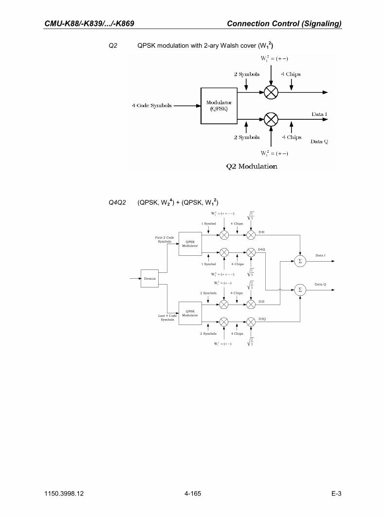
CMU-K88/-K839/.../-K869 Connection Control (Signaling)
1150.3998.12 4-165 E-3
Q2 QPSK modulation with 2-ary Walsh cover (W12)
Q4Q2 (QPSK, W2
4) + (QPSK, W12)
QPSK Modulator
1 Symbol
1 Symbol
4 Chips
4 Chips
Demux
First 2 Code Symbols
QPSK Modulator
2 Symbols
2 Symbols
4 Chips
4 Chips
Last 4 Code Symbols
∑Data I
Data Q
)(W 42 −−++=
)(W 42 −−++=
)(W 21 −+=
)(W 21 −+=
31
32
32
31
D4I
∑
D4Q
D2I
D2Q

Connection Control (Signaling) CMU-K88/-K839/.../-K869
1150.3998.12 4-166 E-3
E4E2 (8-PSK, W24) + (8-PSK, W1
2)
8-PSK Modulator
1 Symbol
1 Symbol
4 Chips
4 Chips
Demux
First 3 Code Symbols
8-PSK Mapping
2 Symbols
2 Symbols
4 Chips
4 Chips
Last 6 Code Symbols
)(W 42 −−++=
)(W 42 −−++=
)(W 21 −+=
)(W 21 −+=
31
32
32
31
∑Data I
Data Q
E4I
∑
E4Q
E2I
E2Q
Remote control: [SENSe]:RFANalyzer:DCHannel:MTYPe:MODE AUTO | B4 | Q4 | Q2 |
Q4Q2 | E4E2 Miscellaneous Settings (Connection Control – Misc.)
The popup menu Misc. provides various general settings to control the MMI behavior and the measurements.
Figure 4-4-73 Connection Control – Miscellaneous

CMU-K88/-K839/.../-K869 Connection Control (Signaling)
1150.3998.12 4-167 E-3
User Guidance The User Guidance section provides settings to control the automatic switchover between menus of the user interface and between measurement environments. Default Settings Returns all User Guidance settings to their default values
Remote control: CONFigure:MENU:CCTRl:...
Connection Control Behaviour
Defines in what instances the Connection Control popup menu is automatically opened or closed: Auto Open if not connected In the Auto Open mode, the Connection Control menu
is automatically opened each time the 1xEV-DO function group is accessed in Signaling test mode, each time a measurement menu is opened while the AT is not connected and each time a connection is lost. Otherwise the menu must be opened manually.
Auto Close if Connected In the Auto Close automatically mode, the Connection Control menu is automatically closed as soon as the CMU reaches the Connected/Call Established state. Otherwise the menu must be closed manually.
Remote control:
CONFigure:MENU:CCTRl:AOPen ON | OFF CONFigure:MENU:CCTRl:ACLose ON | OFF
RF Selectivity Selects the bandwidth of the analog receiver filter (available with RX/TX Board turn 13):
WIDe Normal filter, appropriate for all TX measurements
IFLevel Sets the bandwidth to the IF output level, which is in the TX path
relative to the maximum IF input/output level. The IF level value is equal to the I/Q output level in the TX path relative to the maximum I/Q input voltage.
Remote control:
CONFigure:RF:SELectivity WIDE | IFL
Low Spur Mode For the MinPower application, the Low Spur Mode reduces the broadband noise of
the transmitter if the receiver is on a very low power level: ON Reduced broadband noise transmission
OFF Normal transmission
Remote control: CONFigure:LSMode ON | OFF

Connection Control (Signaling) CMU-K88/-K839/.../-K869
1150.3998.12 4-168 E-3
Marker Control
Markers are references available with any application displaying a graph of the measurement. This section gives a detailed explanation of how to control each marker type. Marker information specific to an application is located with the application.
The Marker softkey positions up to three markers and a D-line in the test diagram and reads their values. Markers Graphical tools for marking points on the measurement curve
and for numerical output of measured values. The markers are activated by pressing the hotkey and pressing
the ON/OFF key, or entering a value. Values can be entered directly with the keypad or with the Variation knob.
The coordinates of the three markers are indicated in the format Ordinate value (level)/abscissa value (time) in a parameter line above the test diagram. The position of the reference marker is expressed in absolute units (level in dBm or percentage and time in symbols). The delta markers are expressed as absolute or relative values (relative position from the reference marker).
D-Line The D-Line is a horizontal line that can be positioned to mark and read out an arbitrary level in the test diagram.
The Ref hotkey displays the status (On | Off) of the reference marker. Pressing the hotkey displays a popup menu to switch the reference marker on or off (uses the ON/OFF key or the Variation knob).
The reference marker is represented by the symbol in the test diagram. The marker position (abscissa) is determined in the input field Ref. Marker. The marker can be positioned to arbitrary time values. If its position is outside the diagram area it will be invisible and its coordinates will be “- - - / <abscissa_value>“. The marker is switched off in the default setting (OFF). The marker level is defined by the measurement curve at the marker position.
The Marker hotkey displays the status (On | Off) of marker 1. Pressing the hotkey displays a popup menu to switch the marker 1 on or off (uses the ON/OFF key or the Variation knob).
Marker 1 is represented by the symbol in the test diagram. The marker position (abscissa) is defined in the input field Marker 1. The marker can be positioned to arbitrary time values. If its position is outside of the diagram area it will be invisible and its coordinates will be “<abscissa_value> / - - -“. The marker is switched off in the default setting (Off). The marker level is defined by the trace at the marker position.
Pressing the hotkey twice displays the Marker 1 Config popup display. It defines whether the position of delta marker 1 is measured and indicated in absolute units (of the horizontal scale) or relative to the reference marker.
The Marker hotkey switches the marker 2 on or off (use the ON/OFF key).
The functions and control are identical to marker 1.

CMU-K88/-K839/.../-K869 Connection Control (Signaling)
1150.3998.12 4-169 E-3
The D-Line hotkey activates and controls the position of the D-Line in the test diagram.
The D-line is a horizontal, colored auxiliary line in the test diagram used for marking a level value and for measuring level differences.
Press the hotkey once to turn the D-Line on or off (using the ON/OFF key). The level of the D-line is determined by entering an absolute or relative value with either the keypad or Variation knob.
Press the hotkey twice to open the D-Line Config popup to set the absolute or relative D-Line display.
In the absolute setting, the D-Line is expressed in the vertical scale units and is limited to the value range of the vertical scale. In the relative setting, the D-Line value is relative to the maximum vertical scale. The default setting is Off.

CMU-K88/-K839/.../-K869 Contents of Chapter 5
1150.3998.12 I-5.1 E-3
Contents
5 Remote Control – Basics.....................................................................................5.1
Structure and Order of Commands ................................................................................................5.1
Measurement Control ......................................................................................................................5.2 Measurement Groups ..............................................................................................................5.2 Measurement Statistics............................................................................................................5.3 Specifying Limits ......................................................................................................................5.5
Status Reporting System.................................................................................................................5.5
Special Terms and Notations ..........................................................................................................5.7


CMU-K88/-K839/.../-K869 Remote Control - Basics
1150.3998.12 5.1 E-3
5 Remote Control – Basics
This chapter gives a summary of the basic features and concepts of 1xEV-DO remote control com-mands. Remote control can be described in terms analogous to the ones used in chapter 3 for the clas-sification of menus and settings for the graphical user interface. In the following, the similarities and differences between manual and remote control are emphasized.
Structure and Order of Commands
Chapter 6 of this manual gives a description of all 1xEV-DO remote control commands, including their parameters, default values and ranges of all numerical parameters. Addressing The CMU 200/300 uses extended addressing. The instrument is assigned a
primary address while each function group and test mode is identified via a sec-ondary address. This allows the same remote commands to be used in several function groups and modes: ibwrt(h_EVDO1xAT_NSig, "INITiate:NPOWer")ibwrt(h_EVDO1xAT_Sig, "INITiate:NPOWer")
provided that the variables h_EVDO1xAT_NSig and h_EVDO1xAT_Sig have been appropriately defined, see program examples in chapter 7 of the CMU Op-erating manual.
The remote control commands for first (SYST:COMM:GPIB:ADDR) and secon-dary (SYST:REM:ADDR:SEC) addressing are described in the CMU operating manual. The SYST:REM:ADDR:SEC command uses the following name to ad-dress the 1xEV-DO non-signaling network tests described in this manual: EVDO1XAT_NSig
Order of commands The commands are arranged to form groups belonging to the same measure-
ment or to the same type of configurations. These command groups are identi-fied by the second-level keyword (as in POWer). Applications belonging to a measurement group (see chapter 5 of the CMU 200/300 base unit operating manual) are identified by the third-level keyword of each command (as in MODu-lation: EVMagnitude). Chapter 6 is organized as follows:
1xEV-DO: • General purpose commands that are identical or almost identical in every
function group (OPTion, STATus:OPERation, RESet, MMEMory, IQIF)
• General configurations that are valid for the entire 1xEV-DO function group (second-level keywords NETWork, LEVEL, INTernal, EXTernal,RFANalyzer, RFGenerator, INPut, OUTPut, CORRection:LOSS,DM:CLOCk)
• Measurement groups: (second/third-level keywords WPOWer, NPOWer,MODulation:MQUality, MODulation:OVERview, MODula-tion:EVMagnitude, MODulation:PERRor, MODulation:MERRor,MODulation:IQANalyzer, CDPower:CDPW, CDPower:PCDep,CDPower:CHPW, SPECtrum:ACP).
The structure of chapter 6 differs from chapter 4 (Functions and their Applica-tion) where the measurements are presented first and configurations pertaining to the whole function group and test mode are reported at the end of each sec-tion.

Remote Control - Basics CMU-K88/-K839/.../-K869
1150.3998.12 5.2 E-3
The menu of the graphical user interface corresponding to a group of commands is quoted at the beginning of each section. A list of all commands is appended to chapter 6.
SCPI Conformity In view of the particular requirements of 1xEV-DO measurements not all com-mands could be taken from the SCPI standard. However, the syntax and struc-ture of all commands is based on SCPI conventions. For a detailed description of the SCPI standard refer to chapter 5 of the operating manual for the CMU basic unit.
SPCI confirmed and SPCI approved commands are explicitly marked in chap-ter 6.
Remote Control All commands may be used for control of the CMU via the GPIB interface or serial (RS-232) interface.
Measurement Control
The commands in the measurement groups WPOWer, NPOWer, POWer..., MODulation..., CDPower... have an analogous structure and syntax. The measurements are controlled according to common concepts which are explained in detail in chapter 5 of the CMU operating manual. The follow-ing sections show how the general concepts are applied to 1xEV-DO measurements.
Measurement Groups
The measurement groups are referred to as measurement objects (keyword <meas_obj>) in remote control. Most measurement objects correspond to a measurement group or application in manual con-trol. For 1xEV-DO measurements, the following measurement objects are defined:
Table 5-1 Measurement objects in 1xEV-DO.
1xEV-DO
Meas. Object Measurement group Application
WPOWer Wide-band Power measurement.
NPOWer Narrow-band Power measurement.
MODulation:MQUality Modulation Quality measurement (H-PSK) AT power, waveform quality, frequency error, transmit time error, carrier feedthrough, I/Q im-balance and sideband suppression. Statistical results and the results of the limit check can be evaluated.
MODulation:OVERview
Modulation Overview measurement (H-PSK) H-PSK scalar modulation results. Summary of phase error, error vector magnitude and magni-tude error of the AT transmitter output signal. The frequency error, average and RMS error, statistical results and the results of the limit check can be evaluated.

CMU-K88/-K839/.../-K869 Remote Control - Basics
1150.3998.12 5.3 E-3
1xEV-DO
Meas. Object Measurement group Application
MODulation:EVMagnitude Modulation Error Vector Magnitude measurement (H-PSK) Modulation waveform interval as a function of time of the AT transmitter output signal (H-PSK). The frequency error, average and RMS error, statistical results and the results of the limit check can be evaluated.
MODulation:MERRor Modulation Magnitude Error measurement (H-PSK) Modulation waveform interval as a function of time of the AT transmitter output signal (H-PSK). The frequency error, average and RMS error, statistical results and the results of the limit check can be evaluated.
MODulation:PERRor Modulation Phase Error measurement (H-PSK) Modulation waveform interval as a function of time of the AT transmitter output signal (H-PSK). The frequency error, average and RMS error, statistical results and the results of the limit check can be evaluated.
MODulation:IQANalyzer Modulation IQ Analyzer (H-PSK) Analysis of the AT signal in the I/Q plane.
CDPower:CDPW Code Domain Power measurement (H-PSK) Code Domain Power in 16 code domain channels contributing to the reverse link 1xEV-DO signal. The slots for the Pilot and the RRI channel are evaluated within the same measurement shot. The AT power, carrier feedthrough, frequency error and rho factor, statistical results and the results of the limit check can be evaluated.
CDPower:PCDep Peak Code Domain Error Power measurement (H-PSK) Peak Code Domain Error Power in 16 code domain channels contributing to the reverse link 1xEV-DO signal. The slots for the Pilot and the RRI channel are evaluated within the same measurement shot. The AT power, carrier feedthrough, frequency error and rho factor, statisti-cal results and the results of the limit check can be evaluated.
CDPower:CHPW Channel Power measurement (H-PSK) Channel Power of the reverse link physical channels of both the I and Q signal. The slots for the Pilot and the RRI channel are evaluated within the same measurement shot. The AT power, carrier feedthrough, frequency error and rho factor, statistical results and the results of the limit check can be evaluated.
SPECtrum:ACP Adjacent Channel Power Spectrum measurement Power as a function of the offset frequency related to the Channel Power. Statistical results and the results of the limit check can be evaluated.
Measurement Statistics Together with the Statistic Count, the Repetition Mode defines how many evaluation periods are meas-ured if the measurement is not stopped explicitly (measurement control commands STOP..., ABORT...) or by a limit failure. With remote control, the two repetition modes Single Shot and Continu-ous are available (Counting is not available in manual control, see chapter 3).
Generally four different traces are determined within one measurement: • The result in the current period • The maximum result • The minimum result • The average result (evaluated over a set number of waveform intervals)

Remote Control - Basics CMU-K88/-K839/.../-K869
1150.3998.12 5.4 E-3
The four results can be queried independently.
Table 5-2 Repetition mode in remote control
Setting Description Command
Statistic Count Integer number of evaluation periods forming one statistics cycle. An evaluation period is equal to a burst.
CONFigure:<meas_obj>:CONTrol:STATistics 1 ... 1000 | NONE
(<meas_obj> = NPOWer | MODulation:MQUality | MODulation:EVMagnitude | CDPower:CHPW | ...)
Repetition Mode
Single Shot
The measurement is stopped after one statistics cycle. All remote control meas-urements default to single shot.
CONFigure:<meas_obj>:CONTrol:REPetition SINGleshot, <StopCondition>, <Stepmode> (<meas_obj> = NPOWer | MODulation:MQUality | MODulation:EVMagnitude | CDPower:CHPW | ...)
Continuous The measurement is continued until stopped explicitly or by a limit failure. Av-erage results are calculated according to the rules described in chapter 3.
CONFigure:<meas_obj>:CONTrol:REPetition CONTinuous, <StopCondition>, <Stepmode> (<meas_obj> = NPOWer | MODulation:MQUality | MODulation:EVMagnitude | CDPower:CHPW | ...)
Counting Repeated single shot measurement with configured statistics cycles.
CONFigure:<meas_obj>:CONTrol:REPetition 1 ... 10000, <StopCondition>, <Stepmode> (<meas_obj> = NPOWer | MODulation:MQUality | MODulation:EVMagnitude | CDPower:CHPW | ...)
A counting measurement with 1 evaluation period is equivalent to a single shot measurement..
Traces The specifiers CURRent, MMAX, and AVERage denote the traces for the current evaluation period, the extreme value, and the average of a set of evaluation periods. They correspond to the Display Mode set in the measurement configuration menus.
In general all four traces are evaluated during the measurement. They are se-lected via the specifiers used as last key-words in the READ..., FETCh... or SAMPle... queries.
Measurement results: READ:ARRay:<meas_obj>:<disp>? READ:SUBarrays:<meas_obj>:<disp>? ...
<disp> = CURRent | AVERage | MAXimum | MINimum | MMAX (not all modes are available for all measurements)
(<meas_obj> = NPOWer | MODulation:MQUality | MODulation:EVMagnitude | CDPower:CHPW | ...)
Limit matching: CALCULATE[:SCALar]:<meas_obj>:<disp>: MATChing:LIMit? <Response> ....
<Response> contains the limit matching identifiers for all three traces

CMU-K88/-K839/.../-K869 Remote Control - Basics
1150.3998.12 5.5 E-3
Specifying Limits
The following table gives an overview of the types of limits and possible results of the limit check.
Table 5-3 Limits and limit check
Type Description Command
Scalar limits Limit values for a single (scalar) measured quantity. Depending on the measured quan-tity, either an upper limit or upper and lower limits can be defined.
CONFigure:<meas_obj>:<disp>:LIMit [:SCALar]:<symmetry>:<Spec.>:VALue <disp> = CURRent | AVERage | MMAX | CAMMax where CAMMax denotes a limit valid for all measure-ment curves (current and average and min/maximum)
(<meas_obj> = NPOWer | MODulation:MQUality | MODulation:EVMagnitude | CDPower:CHPW | ...)
<symmetry> = SYMMetric | ASYMmetric for symmetric or asymmetric upper and lower limits
<Spec.> = UPPer | LOWer | [:COMBined]
for upper limits, lower limits, or combined upper and lower limits.
All scalar limits belonging to the same meas-urement group are read out together with the command on the right side.
CALCulate:<meas_obj.>:MATChing:LIMit? (<meas_obj> = NPOWer | MODulation:MQUality | MODulation:EVMagnitude | CDPower:CHPW | ...)
Limit check
Possible results of the scalar limit check are listed on the right side.
NMAU not matching, underflow NMAL not matching, overflow INV measured value invalid OK no limit failure
The result of the limit check depends on the statistics settings (see section Measurement Statistics on page 5.3).
CALCULATE:ARRay:<meas_obj>:<disp> :MATChing:LIMit? .... where <disp> = :CURRent | :AVERage | | :MMAXimum | :MAXimum | :MINimum (<meas_obj> = NPOWer | MODulation:MQUality | MODulation:EVMagnitude | CDPower:CHPW | ...)
Status Reporting System
A general description of SCPI status registers and of the status reporting system is given in chapter 5 of the CMU 200/300 operating manual. This section is devoted to the particular features concerning 1xEV-DO measurements.
The CMU offers 30 independent STATus:OPERation:SUM1|2:CMU<nr> sub-registers (<nr>=1 ... 15) which are implemented in hierarchical form. The bits of the 30 STATus:OPERation registers are set only after the registers are assigned to a function group and measurement mode.
In the EVENt part, the STATus:OPERation register contains information on which actions the instrument has executed since the last readout. All five parts of the registers can be read using one of the com-mands of the subsystem STATus:OPERation:SUM1|2:CMU<nr>:...

Remote Control - Basics CMU-K88/-K839/.../-K869
1150.3998.12 5.6 E-3
Note: Symbolic status register evaluation by means of the commands STATus:OPERation: SYMBolic:ENABle and STATus:OPERation:SYMBolic[:EVENt]? is a convenient alter-native method of retrieving status information. See also section Symbolic Status Event Regis-ter Evaluation in chapter 5 of the CMU operating manual and chapter 6 of this manual.
1xEV-DO access terminal tests comprise the Non-Signaling factory test mode. The secondary address of the 1xEV-DO function group must be used to access the correct status registers. The bit assignment is as follows:
Table 5-4 1xEV-DO bits used in the STAT:OPER:SUM1|2:CMU<nr> sub-registers (for Non-Signaling)
Bit-No. Description Symbol in STAT:OPER:SYMB...
Firmware Version
0 Forward traffic (AT1) packet stream completed
This bit is set when all packets specified in the Packet Count parameter are sent to the access terminal°1
PS1C V3.40
1 Forward traffic (AT2) packet stream completed
This bit is set when all packets specified in the Packet Count parameter are sent to the access terminal°2
PS2C V3.40
2 Forward traffic (AT3) packet stream completed
This bit is set when all packets specified in the Packet Count parameter are sent to the access terminal°3
PS3C V3.40
3 Forward traffic (AT4) packet stream completed
This bit is set when all packets specified in the Packet Count parameter are sent to the access terminal°4
PS4C V3.40
4 Measurement Invalid
This bit is set when a measurement returns invalid results. MINV V3.40
11 RF Input Overdriven
This bit is set if the RF input level at connector RF1, RF2 or RF 4 IN is larger than the specified RF Max. Level plus an appropriate margin.
RFIO V3.40
12 RF Input Underdriven
This bit is set while the RF input level at connector RF1, RF2 or RF 4 IN falls below the measurement range controlled by the specified RF Max. Level.
RFIU V3.40
Table 5-5 1xEV-DO bits currently used in the STAT:OPER:SUM1|2:CMU<nr> sub-registers (for Sig-naling)
Bit-No. Description Symbol in STAT:OPER:SYMB...
Firmware Version
4 Measurement Invalid
This bit is set when a measurement returns invalid results. MINV V4.20
11 RF Input Overdriven
This bit is set if the RF input level at connector RF1, RF2 or RF 4 IN is larger than the specified RF Max. Level plus an appropriate margin.
RFIO V4.20
12 RF Input Underdriven
This bit is set while the RF input level at connector RF1, RF2 or RF 4 IN falls below the measurement range controlled by the specified RF Max. Level.
RFIU V4.20

CMU-K88/-K839/.../-K869 Remote Control - Basics
1150.3998.12 5.7 E-3
Special Terms and Notations
Below some particular features in the syntax of the 1xEV-DO commands are listed. The general de-scription of the SCPI command syntax can be found in chapter 5 of the CMU operating manual, section "Structure and Syntax of Device Messages". Description of commands
The commands are arranged in tables; all of them are described along the same scheme. From top to bottom, the table rows contain the following en-tries:
1. Complete command syntax including the parameter list and a short description of the command
2. List and description of the parameters with their default values, the de-fault units and unit rings
3. Detailed description of the command, signaling state required for com-mand execution (in Signaling mode), required firmware version
Detailed lists of default values are annexed to the command description.
Order of commands The commands are arranged according to their function. The general purpose
of a command is described by the keyword in the second level. Lower-level keywords define the command in more detail. This means that commands with the same second-level, third-level etc. keywords are generally grouped together in the same sections.
Example: CONFigure:MODulation:PERRor:HPSK:CONTrol:STATistics <Statistics>
Commands with the keyword MODulation in the second level belong to the modulation measurement. The keywords in the third, fourth and fifth level indicate that the command defines the number of bursts forming a statistics cycle in the measurement of the AT phase error.
Combined measurements
To limit the number of remote control commands in an application program, all scalar results of a measurement group are usually measured together and returned in a common list. Arrays (e.g. the traces for CDPOWer and MODula-tion measurements) are returned as comma-separated lists of values; it is possible to retrieve either the whole list (see commands READ:ARRay... etc.) or the values located in a number of subranges that are part of the total measurement range (see commands READ:SUBarrays...; the subarrays are defined via CONFigure:SUBarrays...).
Parameters Many commands are supplemented by a parameter or a list of parameters.
Parameters either provide alternative options (setting a or setting b or setting c ..., see special character "|"), or they form a comma-separated list (setting x,y).
<Par_Name> Alternative settings are described by a common name (literal) written in angle brackets (<>). This literal serves as a description of the parameters only; in an application program it must be replaced by one of the settings given in the detailed parameter description.
Example: CONFigure:MODulation:PERRor:HPSK:CONTrol:STATistics <Statistics>

Remote Control - Basics CMU-K88/-K839/.../-K869
1150.3998.12 5.8 E-3
with <Statistics> = 1 ... 10000 | NONE
possible command syntax: CONF:MOD:PERR:CONT:STAT NONE
NAN NAN (not a number) is generally used to represent missing data, e.g. if a por-tion of a trace has not been acquired yet. It is also returned after invalid mathematical operations such as division by zero. As defined in the SCPI standard, NAN is represented as 9.91 E 37.
INV INV (invalid) is returned if a limit check is performed without defining the ap-propriate tolerance values.
Upper / lower case Upper/lower case characters characterize the long and short form of the key-words in a command. The short form consists of all upper-case characters, the long form of all upper case plus all lower case characters. Either the short form or the long form are allowed; mixed forms are not generally recognized. The instrument itself does not distinguish upper case and lower case charac-ters.
Special characters
| A vertical stroke in the parameter list characterizes alternative parameter set-tings. Only one of the parameters separated by | must be selected.
Example: The following command has two alternative settings: DEFault:LEVel ON | OFF
[ ] Key words in square brackets can be omitted when composing the command header (see chapter 5 of the CMU operating manual, section "Structure of a Command"). The complete command must be recognized by the instrument for reasons of compatibility with the SCPI standard.
Parameters in square brackets are optional as well. They may be entered in the command or omitted.
[?]
Remote control commands that can also be used as a query are indicated with [?] at the end of the command. As a query, the “?” (question mark) must be part of the command.
Braces or curly brackets enclose one or more parameters that may be in-cluded zero or more times.
<nr> This symbol stands for a numeric suffix, e.g. an enumeration index for input and output connectors.
List of Commands
Command: The Command column of the table contains all remote control commands arranged according to their function (configurations or measurement objects).
Parameters: The Parameter column lists the parameters of the commands.
Remarks: The Remarks column gives additional information about the commands which
• Have no query form (no query)
• Have only a query form (query only)
• Can be used both as setting commands and as queries (with query, this applies to all commands belonging to one of the two preceding categories)

CMU-K88/-K839/.../-K869 Contents of Chapter 6
1150.3998.12 I-6.1 E-3
Contents
6 Remote Control – Commands............................................................................ 6.1
General Commands..........................................................................................................................6.1 Option Query............................................................................................................................6.1 Partial Reset.............................................................................................................................6.2 Configuration File Management...............................................................................................6.2 I/Q-IF Interface .........................................................................................................................6.3 Symbolic Status Event Register Evaluation.............................................................................6.6
Connection Control (Non-Signaling Only) .....................................................................................6.7 Band Class – Network Standard..............................................................................................6.7
NETWork Standard........................................................................................................6.7 Analyzer ...................................................................................................................................6.8
Subsystem RFANalyzer.................................................................................................6.8 Subsystem FREQuency ...................................................................................6.9 Subsystem SUBType .....................................................................................6.11 Subsystem LCMask (Long Code Mask).........................................................6.11 Subsystem CCFilter (Code Channel Filter) ....................................................6.12 Subsystem AT<nr> (Access Terminal)...........................................................6.14 Subsystem DCHannel (Data Channel Modulation)........................................6.14
Generator ...............................................................................................................................6.15 Subsystem RFGenerator .............................................................................................6.15
Subsystem FREQuency .................................................................................6.16 Subsystem POWer.........................................................................................6.18 Subsystem PROPerty.....................................................................................6.18 Subsystem IMPairments ................................................................................6.19 Subsystem SNCMessage (Sync. Message) ..................................................6.20 Subsystem Access Terminal AT<nr> (for CMU-B88) / AT1 (for CMU-B89) .6.22 Subsystem RAB (Reverse Activity) ................................................................6.32 Subsystem OAT (Other Access Terminals) ...................................................6.34 Subsystem Type.............................................................................................6.34 Subsystem I/Q Access Interface Setup..........................................................6.35
RF Input and Output...............................................................................................................6.37 Subsystem RF Input and Output (External Attenuation at Connectors)......................6.37
WPOWer (Wide Band Power)................................................................................................6.38 Control of Measurement ..............................................................................................6.38 Test Configuration........................................................................................................6.39
Subsystem CONTrol.......................................................................................6.39 Measured Values .........................................................................................................6.40
DM:CLOCk (Synchronization)................................................................................................6.40 Trigger ....................................................................................................................................6.41
Subsystem TRIGger ....................................................................................................6.41 Subsystem SELect .........................................................................................6.41 Subsystem SLOPe .........................................................................................6.41 Subsystem OUTPut........................................................................................6.42 Subsystem THReshold...................................................................................6.43 Subsystem SOURce.......................................................................................6.44
Subsystem RF Selectivity and Rx/Tx Frequency Coupling ...................................................6.45 Subsystem RF Selectivity...............................................................................6.45 Subsystem Rx/Tx Frequency Coupling ..........................................................6.46

Contents of Chapter 6 CMU-K88/-K839/.../-K869
1150.3998.12 I-6.2 E-3
Measurement Command Groups (Non-Signaling Only).............................................................6.47 MODulation:MQUality (App. Modulation Quality HPSK)........................................................6.47
Control of Measurement ..............................................................................................6.47 Test Configuration........................................................................................................6.48
Subsystem CONTrol.......................................................................................6.48 Subsystem LIMit .............................................................................................6.51
Measured Values .........................................................................................................6.54
Common Measurements and Command Groups (Signaling and Non-Signaling)...................6.56 NPOWer (Narrow Band Power) .............................................................................................6.56
Control of Measurement ..............................................................................................6.56 Test Configuration........................................................................................................6.58
Subsystem CONTrol.......................................................................................6.58 Measured Values .........................................................................................................6.59
SAPPower (Standby and Access Probe Power) ...................................................................6.60 MODulation:OVERview..........................................................................................................6.61
Control of Measurement ..............................................................................................6.61 Test Configuration........................................................................................................6.62
Subsystem CONTrol.......................................................................................6.62 Subsystem LIMit .............................................................................................6.65
Measured Values .........................................................................................................6.68 MODulation:EVMagnitude (Error Vector Magnitude).............................................................6.69
Control of Measurement ..............................................................................................6.69 Test Configuration........................................................................................................6.71
Subsystem CONTrol.......................................................................................6.71 Subsystem LIMit .............................................................................................6.73 Subsystem SUBarrays ...................................................................................6.73
Measured Values .........................................................................................................6.74 MODulation:MERRor (Appl. Magnitude Error H-PSK)...........................................................6.76
Control of Measurement ..............................................................................................6.76 Test Configuration........................................................................................................6.77
Subsystem CONTrol.......................................................................................6.77 Subsystem LIMit .............................................................................................6.78 Subsystem SUBarrays ...................................................................................6.79
Measured Values .........................................................................................................6.80 MODulation:PERRor (Application Phase Error H-PSK) ........................................................6.82
Control of Measurement ..............................................................................................6.82 Test Configuration........................................................................................................6.83
Subsystem CONTrol.......................................................................................6.83 Subsystem LIMit .............................................................................................6.85 Subsystem SUBarrays ...................................................................................6.85
Measured Values .........................................................................................................6.86 MODulation:IQANalyzer (IQ Analyzer H-PSK) ......................................................................6.88
Control of Measurement ..............................................................................................6.88 Test Configuration........................................................................................................6.89
Subsystem CONTrol.......................................................................................6.89 Subsystem SUBarrays ...................................................................................6.90
Measured Values .........................................................................................................6.91 SPECtrum:ACP (ACP Spectrum) ..........................................................................................6.92
Control of Measurement ..............................................................................................6.92 Test Configuration........................................................................................................6.93
Subsystem CONTrol.......................................................................................6.93

CMU-K88/-K839/.../-K869 Contents of Chapter 6
1150.3998.12 I-6.3 E-3
Subsystem LIMit .............................................................................................6.97 SPECtrum:ACP:LIMit .........................................................................6.97
Measured Values .........................................................................................................6.97 CDPower:CDPW (Code Domain Power) .............................................................................6.100
Control of Measurement ............................................................................................6.100 Test Configuration......................................................................................................6.101
Subsystem CONTrol.....................................................................................6.101 Subsystem LIMit ...........................................................................................6.103
CDPower:CPCCommon:LIMit ..........................................................6.103 CDPower:CDPW:LIMit .....................................................................6.105
Measured Values .......................................................................................................6.106 CDPower:PCDep (Peak Code Domain Error Power) ..........................................................6.112
Control of Measurement ............................................................................................6.112 Test Configuration......................................................................................................6.113
Subsystem CONTrol.....................................................................................6.113 Subsystem LIMit ...........................................................................................6.115
CDPower:CPCCommon:LIMit ..........................................................6.115 CDPower:PCDep:LIMit ....................................................................6.115
Measured Values .......................................................................................................6.116 CDPower:CHPW (Channel Power)......................................................................................6.121
Control of measurement ............................................................................................6.121 Test Configuration......................................................................................................6.122
Subsystem CONTrol.....................................................................................6.122 Subsystem LIMit ...........................................................................................6.125
CDPower:CPCCommon:LIMit ..........................................................6.125 CDPower:CHPW:LIMit .....................................................................6.125
Measured Values .......................................................................................................6.126
Measurement Command Groups (Signaling Only) ...................................................................6.132 RxQuality (Receiver Quality)................................................................................................6.132
Control of Measurement - Common Commands.......................................................6.132 Test Configuration......................................................................................................6.133
Statistics Overview Application ....................................................................6.133 Measured Values .............................................................................6.133
Control Channel PER Application ................................................................6.134 Measured Values .............................................................................6.136
Forward Link PER Application......................................................................6.137 Measured Values .............................................................................6.139
Reverse Link Quality Application..................................................................6.140 Measured Values .............................................................................6.142
Forward Link Performance Application ........................................................6.143 Measured Values .............................................................................6.145
Reverse Link Performance Application ........................................................6.145 Measured Values .............................................................................6.146
Reverse Link PER Application .....................................................................6.148 Measured Values .............................................................................6.150
Data Applications - RLP Frame / IP Statistics and Ping ......................................................6.152 Control of Measurement - Common Commands.......................................................6.152
Test Configuration – RLP Frame / IP Statistics Application .........................6.152 Test Configuration – Ping Application ..........................................................6.153
Subsystem PING:CONTrol ........................................................................................6.154 Measured Values – RLP Frame / IP Statistics.................................6.156 Measured Values – Ping ..................................................................6.157
Connection Control (Signaling Only) .........................................................................................6.157

Contents of Chapter 6 CMU-K88/-K839/.../-K869
1150.3998.12 I-6.4 E-3
Subsystem Signaling (Connection Setup and Cleardown) ..................................................6.158 Subsystem AT Information ........................................................................................6.160
Subsystem Handoff..............................................................................................................6.161 Subsystem Layer .................................................................................................................6.161
Subsystem Default Signaling Application ..................................................................6.162 Subsystem Default Test Application ..........................................................................6.163 Subsystem Enhanced Test Application .....................................................................6.168 Subsystem Default Packet Application ......................................................................6.172 Subsystem Stream Layer ..........................................................................................6.178 Subsystem Session Layer .........................................................................................6.179 Subsystem Connection Layer....................................................................................6.180 Subsystem MAC Layer ..............................................................................................6.181 Subsystem Physical Layer.........................................................................................6.191
Subsystem ANSignal ...........................................................................................................6.191 Subsystem Power Control .........................................................................................6.193 Subsystem Sector......................................................................................................6.194 Subsystem Access Network Properties.....................................................................6.196 Subsystem AT Forward Packet Activity.....................................................................6.197
Subsystem Band Class – NETWork Standard.....................................................................6.197 Subsystem RFANalyzer .......................................................................................................6.203
Subsystem LEVel.......................................................................................................6.204 Subsystem SUBType.................................................................................................6.204 Subsystem CCFilter (Code Channel Filter) ...............................................................6.205 Subsystem DCHannel (Data Channel Modulation) ...................................................6.207
External Synchronization .....................................................................................................6.208 Subsystem ESYNc.....................................................................................................6.208
Trigger ..................................................................................................................................6.210 Subsystem TRIGger ..................................................................................................6.210
Subsystem SOURce.....................................................................................6.210 Subsystem THReshold.................................................................................6.211 Subsystem SLOPe .......................................................................................6.211 Subsystem OUTPut......................................................................................6.212
Subsystem Miscellaneous (User Guidance and RF Selectivity)..........................................6.212 Subsystem User Guidance (Connection Control Behavior) ......................................6.212 Subsystem RF Selectivity ..........................................................................................6.213 Low Spur Mode..........................................................................................................6.213
Subsystem WPOWer (Wide Band Power)...........................................................................6.213 Control of Measurement ............................................................................................6.213 Test Configuration......................................................................................................6.215
Subsystem CONTrol.....................................................................................6.215 Measured Values..........................................................................................6.215
List of Commands ........................................................................................................................6.214

CMU-K88/-K839/.../-K869 Option Query
1150.3998.12 6.1 E-3
6 Remote Control – Commands
This chapter contains all remote-control commands for the 1xEV-DO function group. The commands are presented in tabular form with their parameters and the ranges of values. The structure of this chap-ter is analogous to that of the reference part for manual operation (chapter 4).
• The chapter starts with a summary of general commands, which are global CMU features sup-ported in the 1xEV-DO function group
• The measurement modes Non-Signaling and Signaling are then presented separately. • Within the 1xEV-DO function group, the general configurations are presented first and then the
individual measurement groups are presented. • Command and measurement groups that are identical or almost identical in both test modes
RFANalyzer...,TRIGger..., WPOWer, etc.) are presented in a separate section between the two measurement modes.
General notes on remote control in the 1xEV-DO function group can be found in chapter 5. An introduc-tion to remote control according to SCPI standard and the status registers of the CMU is given in chap-ter 5 of the operating manual for the CMU 200/300 basic instrument.
Note: Remote control commands that can also be used as a query are indicated with [?] at the end of the command. As a query, the “?” (question mark) must be part of the command.
Otherwise the command documentation follows SCPI conventions (see also chapter 5): Keywords and parameters enclosed in square brackets are optional and can be omitted without changing the effect of the command.
General Commands
The commands listed in this section describe the global CMU features that are supported in the 1xEV-DO function group. These commands are identical or almost identical in all CMU function groups that support the corresponding feature. Option Query
The Options subsystem contains the commands for querying information on the instrument and the available options. It corresponds to the Options tab in the Setup menu opened via the SETUP key on the front panel.

Partial Reset CMU-K88/-K839/.../-K869
1150.3998.12 6.2 E-3
SYSTem:OPTions:INFO:CURRent? Device Info
Response Def. Value Default unit FW vers.
Example: Rohde&Schwarz,CMU 200-1100.0008.02,840675/018, V4.20:SP00 2006-03-10" EVDO1xAT_NSig"
or Rohde&Schwarz,CMU 200-1100.0008.02,840675/018, V4.20:SP00 2006-03-10" EVDO1xAT_Sig"
– – V3.40
V4.20
Command description
This command returns the information on the device comprising the manufacturer, model, serial number and firmware version of the current function group. This command is always a query.
SYSTem:VERSion:SW:MMI? MMI Software Version
Response Def. Value Default unit FW vers.
Example: “1.00C[3.40:SP00]” – – V3.40
Command description
This command returns the information about the current version of the 1xEV-DO MMI module. This command may be helpful for driver development as the MMI module determines the GPIB command set. This command is always a query.
Partial Reset
The RESet subsystem restores the (factory) default values for the 1xEV-DO function group (unless the secondary address of another function group is used). It corresponds to the 1xEV-DO path in the Reset menu opened via the RESET key on the front panel.
SYSTem:RESet:CURRent Partial Reset
Command description FW vers.
This command sets all parameters of the current function group and test mode to default values. The command is available in all function groups. Unlike the Reset menu the remote command re-stores the default values defined for remote control operation. In those cases where remote and manual control use distinct settings (e.g. the repetition mode for many measurements), the manual control settings are left unchanged.
V3.40
Configuration File Management
The MMEMory system provides mass storage capabilities for the CMU. The functionality of this system is included in the Data menu; see CMU 200/300 operating manual.
The mass storage of the CMU may be internal or external. The internal mass storage device is a sec-tion on the internal hard disk that is reserved for mass storage (directory c:\temp). The external mass storage device is either a floppy disk or a PCMCIA memory card, depending on the instrument configu-ration. The <msus> (mass storage unit specifier) parameter in the MMEMory commands denotes the root directory of the INTernal or EXTernal mass storage device.
The <FileName> parameter is a string. The contents of the string may contain characters for specifying subdirectories, e.g. "\TEMP\TRASH\test.txt" for the file named test.txt in the TEMP\TRASH subdirectory of the root directory or "TEMP\TRASH\test.txt" for the file named test.txt in the TEMP\TRASH subdirec-

CMU-K88/-K839/.../-K869 I/Q-IF Interface
1150.3998.12 6.3 E-3
tory of the current directory, to be queried with the base system command MMEM-ory:DIRectory[:CURRent]?. The file name itself may contain the period as a separator for exten-sions.
MMEMory:SAVE:CURRent <FileName> [,<msus>] Save configurations in current function group and test mode
Parameters Parameter description Def. value Def. unit FW vers.
"<FileName>", INTernal | EXTernal
Name of the config. file to be created Storage device of the config. file
– INTernal
– –
V3.40
Command description
This command saves the configuration of the 1xEV-DO function group (unless the secondary address of another function group is used) to a configuration file. A "?" in the specified file name will be replaced by current numbers that are automatically incremented, starting with zero. The auto-increment function overwrites an existing file with a "9" in its file name. For those instrument settings which may be different in manual and remote control (e.g. the repetition mode for many measurements) the manual setting is saved. The command is available in all function groups. This command is CMU-specific.
MMEMory:RECall:CURRent <FileName> [,<msus>] Recall configurations in current function group and test mode
Parameters Parameter description Def. value Def. unit FW vers.
"<FileName>", INTernal | EXTernal
Name of the config. file to be recalled Storage device of the config. file
– INTernal
– –
V3.40
Command description
This command recalls the configuration of the current function group and test mode from a configuration file. The command is available in all function groups. This command is CMU-specific.
I/Q-IF Interface The subsystem IQIF configures the signal paths for I/Q and IF signals provided by option CMU-B17, I/Q and IF Interfaces. It corresponds to the I/Q-IF tab in the second plane of the Connection Control menu.
Hint: How to make sense out of parameter names:
In all path configurations except bypass, both the I/Q and IF output are connected (to either the RF unit, the Digital unit, or one of the I/Q-IF inputs). The paths differ in the connection of the input branches: The qualifier IO denotes a connected input (with connected output), XO denotes a disconnected input (with connected output). Many parameters of the IQIF commands are composed of two IO/XO qualifiers, the first one standing for the IF signal, the second for the I/Q signal.
Example: The parameter IOXO denotes a connected IF input and a disconnected IF output, while both output branches are connected.
For more information see chapter 4 and the application examples in the CMU 200/300 operating man-ual.

I/Q-IF Interface CMU-K88/-K839/.../-K869
1150.3998.12 6.4 E-3
CONFigure:IQIF:RXTXcombined[?] <Scenario> I/Q-IF
<Scenario> Description of parameters Def. value Def. unit FW vers.
DEFault | BYP | BYIQ | XOIO | IOIO | IOXO | FPAT | UDEF
Sets the the I/Q-IF test path configuration to default value RX/TX Bypass, RXPath = BYP, TXPath = BYP Bypass w. I/Q-OF OUT, RXPath = TXPath =BYIQ I/Q IN/OUT, RXPath = TXPath = XOIO IF IN_I/Q IN/OUT, RXPath = TXPath = IOIO IF IN/OUT, RXPath = TXPath = IOXO Fading Path, RXPath = BYP, TXPath = XOIO User-defined scenario, can not be set, but may be returned by the query CONF:IQIF:RXTX?
BYP – V3.40
Description of command
This command selects the I/Q-IF test scenario, overwriting the current RX and TX path settings (see commands CONFigure:IQIF:RXPath and CONFigure:IQIF:TXPath below). Six different predefined test scenarios with fixed RX and TX paths are provided. Additional scenarios may be defined by selecting any other combination of RX and RX paths. Note: UDEF is not provided as a setting parameter. If the RX/TX path combination defined via CONFig-
ure:IQIF:RXPath and CONFigure:IQIF:TXPath doesn't correspond to any of the predefined scenarios, then a user-defined scenario is set implicitly, i.e. the query CONF:IQIF:RXTX? returns the value UDEF.
CONFigure:IQIF:RXPath[?] <Path> RX Path
<Path> Description of parameters Def. value Def. unit FW vers.
DEFault | BYP | BYIQ | XOIO | IOIO | IOXO
Sets the the RX signal path to default value Bypass Bypass w. I/Q-IF OUT I/Q IN/OUT IF IN_I/Q IN/OUT IF IN/OUT
BYP –
V3.40
Description of command
This command selects the RX signal path, leaving the TX path (see command CONFigure:IQIF:TXPath be-low) unchanged but adapting the I/Q-IF test scenario to the new RX/TX path combination: If the combination cor-responds to a predefined scenario, then CONFigure:IQIF:RXTXcombined is set to the predefined scenario; otherwise it is set to UDEF.
CONFigure:IQIF:TXPath[?] <Path> TX Path
<Path> Description of parameters Def. value Def. unit FW vers.
DEFault | BYP | BYIQ | XOIO | IOIO | IOXO
Sets the the TX signal path to default value Bypass Bypass w. I/Q-IF OUT I/Q IN/OUT IF IN_I/Q IN/OUT IF IN/OUT
BYP –
V3.40
Description of command
This command selects the TX signal path, leaving the RX path (see command CONFigure:IQIF:RXPath above) unchanged but adapting the I/Q-IF test scenario to the new RX/TX path combination: If the combination corresponds to a predefined scenario, then CONFigure:IQIF:RXTXcombined is set to the predefined sce-nario; otherwise it is set to UDEF.

CMU-K88/-K839/.../-K869 I/Q-IF Interface
1150.3998.12 6.5 E-3
[SENSe:]IQIF:LEVel? <TX Level> IF Level
<TX Level> Description of parameters Def. value Def. unit FW vers.
< 0 dB IF level -9 dBFS V3.60
Description of command
This command is always a query and returns the IF output level in the TX path relative to the maximum IF output level (PEP) quoted in the data sheet. The value is equal to the I/Q output level in the TX path relative to the maximum I/Q output voltage quoted in the data sheet.
IQIF:DEFault[?] <Enable> Default Settings
<Enable> Description of parameters Def. value Def. unit FW vers.
ON | OFF
The I/Q-IF parameters are set to their default values Some or all parameters differ from the default values
ON
– V3.40
Description of command
If used as a setting command with the parameter ON this command sets all parameters of the subsystem to their default values (the setting OFF causes an error message).
If used as a query the command returns whether all parameters are set to their default values (ON) or not (OFF).

Symbolic Status Event Register Evaluation CMU-K88/-K839/.../-K869
1150.3998.12 6.6 E-3
Symbolic Status Event Register Evaluation The following commands are used to retrieve the events reported in the 1xEV-DO function group. See section Symbolic Status Event Register Evaluation in chapter 5 of the CMU operating manual.
STATus:OPERation:SYMBolic:ENABle <Event>,<Event> Symbolic status evaluation
Parameter list Parameter description Def. Value1 Default Unit FW vers.
NONE | <Event>,<Event>
No event reported List of symbols for events to be reported
NONE – V3.40
Command description
This command enables event reporting for one or several events in the 1xEV-DO function group, i.e. it sets the corresponding bits in the STATus:OPERation:CMU:SUM<nr>:CMU<nr_event>:ENABle register (<nr> = 1 | 2, <nr_event> denotes the current function group) and in all sum registers up to the status byte. The events and the corresponding symbols for the function group are listed in chapter 5 (see section Status Regis-ters). The symbols may be entered in arbitrary order.
STATus:OPERation:SYMBolic[:EVENt]? Symbolic status evaluation
Response Parameter description Def. Value2 Default Unit FW vers.
NONE | <Event>,<Event>
No event in the 1xEV-DO function group List of reported events
NONE – V3.40
Command description
This command is always a query. It lists the events reported in the 1xEV-DO function group and deletes these events in the STATus:OPERation:CMU:SUM<nr>:CMU<nr_event>:EVENt register as well as in all sum reg-isters.
1 The default values quoted in this command are achieved after a STATus:PRESet command. *RST does not overwrite the entries in the status registers; see section Reset Values of the Status Reporting Systems in chapter 5. 2 The default values quoted in this command are achieved after a *CLS command. *RST does not overwrite the entries in the status registers; see section Reset Values of the Status Reporting Systems in chapter 5.

CMU-K88/-K839/.../-K869 Band Class – Network Standard
1150.3998.12 6.7 E-3
Connection Control (Non-Signaling Only)
The remote-control commands presented in this section determine the RF analyzer settings and the signals generated by the CMU, the inputs and outputs used and the reference frequency. They corre-spond to the settings in the popup menu of the softkey Connect.Control, located at the top right of each main menu. The Connection Control settings are general (global) settings that are valid for the entire function group. Band Class – Network Standard
NETWork Standard
The NETWork subsystem switches between the different 1xEV-DO network standards. The network standard determines the channel/frequency assignment for RF analyzer and generator. Furthermore some measurements provide separate default setups for each of the network standards. CONFigure:NETWork:STANdard[?] <Standard> Network Standard <Standard> Description of parameters Def. value Def. Unit FW vers
USC | KCEL | NAPC |
TACS | JTAC | KPCS | N45T | IM2K | NA7C | B18M | NA9C | NA8S | PA4M | PA8M | IEXT | USPC | AWS | U25B | U25F
Band Class 0, US Cellular Band Class 0, Korean Cellular Band Class 1, North American PCS
Band Class 2, TACS Band Class 3, JTACS Band Class 4, Korean PCS Band Class 5, NMT 450 Band Class 6, IMT-2000 Band Class 7, North American 700 MHz Band Class 8, 1800 MHz Band Class 9, North American 900 MHz Band Class 10, Secondary 800 MHz Band Class 11, European 400 MHz PAMR Band Class 12, 800 MHz PAMR Band Class 13, IMT-2000 2.5 GHz Ext. Band Class 14, US PCS 1900 MHz Band Class 15, AWS Band Band Class 16, US 2.5 GHz Band Class 17, US 2.5 GHz Forward Link Only
USC – V3.40 V3.40 V4.20
Description of command
This command activates the test mode according to one of the provided 1xEV-DO network standards.
Note: Changing the network standard will affect the frequency setting of the RF analyzer and the generator as well as the sideband suppression and ACP spectrum measurement. See commands [SENSe]:RFANalyzer:FREQuency SOURce:RFGenerator:FREQuency[:RF] CONFigure:MODulation:MQUality:HPSK:CONTrol:FOFFset:SBSuppress:ACP<nr> CONFigure:SPECtrum:ACP:CONTrol:FOFFset:ACP<nr>

Analyzer CMU-K88/-K839/.../-K869
1150.3998.12 6.8 E-3
Analyzer
In the 1xEV-DO function group, the signal of a 1xEV-DO access terminal (mobile station) is analyzed. The remote-control commands presented in this section determine the RF analyzer settings. They cor-respond to the settings in the popup menu of the softkey Connect Control, located at the top right of each main menu. The Analyzer settings are general (global) settings that are valid for the entire function group. Subsystem RFANalyzer
The subsystem RFANalyzer configures the RF input path by defining the analyzer level and frequency. Furthermore it decodes the input signal in order to extract the relevant part of the signal. It corresponds to the table sections Default All Settings/Analyzer Level in the Analyzer tab in the popup menu Connec-tion Control. DEFault:RFANalyzer[?] RF Analyzer <RF Analyzer> <RF Analyzer> Description of parameters Def. value Def. unit FW vers.
ON | OFF
The parameters are set to their default values The parameters differ from the default values (par-tially or totally)
ON – V3.40
Description of command
If used as a setting command with the parameter ON, this command (re-)sets all parameters of the subsystems RFANAlyzer to their default values (the setting OFF results in an error message).
If used as a query the command returns whether all parameters are set to their default values (ON) or not (OFF).
[SENSe]:LEVel:MODE[?] RF Level Mode <RF Level Mode> <RF Level Mode> Description of parameters Def. value Def. unit FW vers.
AUTomatic | MANual Maximum input level mode for RF AUT – V3.40
Description of command
This command defines whether the maximum expected input level is set manually or set by auto-ranging. Using the default value (auto-ranging) ensures optimized RF input path level settings.
[SENSe]:LEVel:MAXimum[?] Max. RF Level <RF Manual Max Level> <RF Manual Max Level> Description of parameters Def. value Def. unit FW vers.
–43 dBm to +44 dBm –54 dBm to +30 dBm –80 dBm to +9 dBm | MINimum | MAXimum | DEFault
Maximum input level for RF 1 Maximum input level for RF 2 Maximum input level for RF 4 IN Sets the minimum input level Sets the maximum input level Sets the default input level
0.0 0.0 0.0 -43.0 44.0 0.0
dBm dBm dBm dBm dBm dBm
V3.40
Description of command
This command defines the maximum expected input level. The value range depends on the RF input used and the external attenuation set (see [SENSe]:CORRection:LOSS:INPut<nr>[:MAGNitude] command).

CMU-K88/-K839/.../-K869 Analyzer
1150.3998.12 6.9 E-3
Subsystem FREQuency
The subsystem FREQuency controls the frequency in the RF input signal path. It corresponds to the table section Analyzer Settings in the Analyzer tab of the Connection Control menu. [SENSe]:RFANalyzer:FREQuency:UNIT[?] Frequency Unit <Analyzer Freq. Unit> <Analyzer Freq. Unit> Description of parameters Def. Value Def. unit FW vers.
HZ | KHZ | MHZ | GHZ | CH Frequency unit or Channel Number HZ – V3.40
Description of command
This command defines whether the frequency of the RF signal analyzed is specified in frequency units or as a 1xEV-DO channel number. Frequency units must be used to select input signals that are outside the designated channel range.
[SENSe]:RFANalyzer:FREQuency[?] RF Frequency <Frequency> <RF Frequency> Description of parameters Def. Value Def. unit FW vers.
9.990000 MHz to 2700.000000 MHz |
9.990000 MHz to 2700.000000 MHz |
10.000000 MHz to 2700.000000 MHz |
9.987500 MHz to 2699.987500 MHz |
10.000000 MHz to 2700.000000 MHz |
10.000000 MHz to 2700.000000 MHz |
10.000000 MHz to 2700.000000 MHz |
10.000000 MHz to 2700.000000 MHz |
10.000000 MHz to 2700.000000 MHz |
10.000000 MHz to 2700.000000 MHz |
10.000000 MHz to 2700.000000 MHz |
10.000000 MHz to 2700.000000 MHz |
10.000000 MHz to 2700.000000 MHz |
Input frequency Default input frequency for following stan-dards:
Band Class 0, US Cellular
Band Class 0, Korean Cellular
Band Class 1, North American PCS
Band Class 2, TACS
Band Class 3, JTACS
Band Class 4, Korean PCS
Band Class 5, NMT 450
Band Class 6, IMT-2000
Band Class 7, North American 700 MHz
Band Class 8, 1800 MHz
Band Class 9, North American 900 MHz
Band Class 10, Secondary 800 MHz
Band Class 11, European 400 MHz PAMR
833.4900 MHz CH 283
833.4900 MHz CH 283
1857.5000 MHz CH 150
891.9625 MHz CH 79
915.9500 MHz CH 76
1752.2500 MHz CH 45
450.6000 MHz CH 25
1920.6000 MHz CH 12
776.7000 MHz CH 14
1710.8000 MHz CH 16
880.9000 MHz CH 18
807.2500 MHz CH 50
460.2500 MHz CH 11
Hz
V3.40
V3.40
V4.20

Analyzer CMU-K88/-K839/.../-K869
1150.3998.12 6.10 E-3
9.9875 MHz to 2699.987500 MHz |
10.000000 MHz to 2700.000000 MHz |
10.000000 MHz to 2700.000000 MHz |
10.000000 MHz to 2700.000000 MHz |
10.000000 MHz to 2700.000000 MHz |
10.000000 MHz to 2700.000000 MHz |
MINimum |
MAXimum |
DEFault
Band Class 12, 800 MHz PAMR
Band Class 13, IMT-2000 2.5 GHz Ext.
Band Class 14, US PCS 1900 MHz
Band Class 15, AWS Band
Band Class 16, US 2.5 GHz Band
Band Class 17, US 2.5 GHz Forward Link Only Band
Sets the input frequency to network stan-dard-related minimum
Sets the input frequency to network stan-dard-related maximum
Sets the input frequency to network stan-dard-related default (see above)
870.3125 MHz CH 12
2500.6500 MHz CH 13
1850.7000 MHz CH 14
1710.7500 MHz CH 15
2502.50 MHz CH 150
2502.50 MHz CH 150
(depends on band class)
(depends on band class )
(depends on band class)
V4.20
Description of command
This command defines the frequency of the RF signal analyzed. With the command [SENSe]:RFANalyzer:FREQuency:UNIT, the default frequency unit can be changed, and even 1xEV-DO channel numbers can be entered instead of frequencies. In the latter case, the assignment of channel numbers and frequencies meets the specification for the reverse channel (signal direction from access terminal to CMU).
Note: Changing the network standard with the command CONFigure:NETWork:STANdard will also change the analyzer RF frequency.
[SENSe]:RFANalyzer:FOFFset[?] Frequency Offset <Analyzer Freq. Offset> <Analyzer Freq. Offset> Description of parameters Def. value Def. unit FW vers.
–50.0 kHz to +50.0 kHz | ON | OFF
Frequency offset setting Frequency offset on, last setting re-activatedNo frequency offset
OFF Hz V3.40
Description of command
This command determines a frequency offset to the RF signal analyzed.

CMU-K88/-K839/.../-K869 Analyzer
1150.3998.12 6.11 E-3
Subsystem SUBType
The subsystem SUBtype determines the measurement subtype. It corresponds to the table section Analyzer Settings / Meas. Subtype in the Analyzer tab of the Connection Control menu. [SENSe]:RFANalyzer:SUBType[?] Measurement Subtype <Measurement Subtype> <Measurement Subtype> Description of parameters Def. value Def. unit FW vers.
0 | 1 | 2 Measurement subtype (the value "1" is for CMU-B88 only, when 1 is set with CMU-B89, the value is reset to "0")
0 – V4.20
Description of command
Protocols are associated with a Type that denotes the type of the protocol (e.g., Access Channel MAC Protocol) and with a Subtype that denotes a specific instance of a protocol (e.g. the Default Access Channel MAC Protocol).
The measurement subtype affects the protocol subtype of the involved MAC and/or physical layer protocols.
This setting affects the code channel filter settings ([SENSe]:RFANalyzer:CCFilter) and the results of the Code Domain Power measurement (READ:ARRay:CDPower:…). Detailed descriptions of the measurement sub-types are available in chapter 4. Subsystem LCMask (Long Code Mask)
The subsystem LCMask determines the Long Code Mask of the reverse link RF signal. It corresponds to the table section Analyzer Settings / Long Code Mask in the Analyzer tab of the Connection Control menu. [SENSe]:RFANalyzer:LCMask:I:LSB[?] LSB Long Code Mask [SENSe]:RFANalyzer:LCMask:Q:LSB[?] <LSB Long Code Mask> <LSB Long Code Mask> Description of parameters Def. value Def. unit FW vers.
"00000000" to “FFFFFFFF” Hexadecimal formatted string (8 chars) repre-senting the LSB of the long code mask
"00000000" – V3.40
Description of command
This command defines the least significant bits (0 to 31) of the I and Q signal long code masks.
[SENSe]:RFANalyzer:LCMask:I:MSB[?] MSB Long Code Mask [SENSe]:RFANalyzer:LCMask:Q:MSB[?] <MSB Long Code Mask> <MSB Long Code Mask> Description of parameters Def. value Def. unit FW vers.
"000" to “3FF” Hexadecimal formatted string (3 chars) repre-senting the MSB of the long code mask
"000" for I and for Q
– V3.40
Description of command
This command defines the most significant bits (32 to 41) of the I and Q signal long code masks.

Analyzer CMU-K88/-K839/.../-K869
1150.3998.12 6.12 E-3
Subsystem CCFilter (Code Channel Filter)
The subsystem CCFilter determines the reverse link code channels to be evaluated. It corresponds to the table section Analyzer Settings / Code Channel Filter in the Analyzer tab of the Connection Control menu. [SENSe]:RFANalyzer:CCFilter:DRC[?] (for all meas. subtypes) Code Channel Filter [SENSe]:RFANalyzer:CCFilter:ACK[?] (only for meas. subtypes 0 | 1) [SENSe]:RFANalyzer:CCFilter:DATA[?] (for all meas. subtypes) <Code Channel Filter> <Code Channel Filter> Description of parameters Def. Value Def. unit FW vers.
ON | OFF | DCARe
The code channel will be measured unless it is inactive. For inactive channels the CMU returns invalid results (INV). The code channel will not be measured, regard-less of whether it is active or not. Do not care. The measurement will be made when the code channel is not active, which may lead to confusing or rapidly changing results.
DCARe – V3.40
Description of command
Note: If these filters are specified in such a manner that the AT never generates the specified channel configura-tion, the measurements will return invalid results (INV).
These commands determine if the specified reverse link code channel is evaluated. As the DRC, ACK, and Data code channels are not continously present, the code channel filters allow the user to specify the conditions under which the measurements are performed.
The referenced measurement subtypes are defined using [SENSe]:RFANalyzer:SUBType.
[SENSe]:RFANalyzer:CCFilter:APILot[?] (for meas. subtype 2 only) Code Channel Filter <CodeChannelFilter - AuxPilot> <CCFilter - AuxPilot> Description of parameters Def. Value Def. unit FW vers.
ON | OFF | DCARe
The code channel will be measured unless it is inactive. For inactive channels the CMU returns invalid results (INV). The code channel will not be measured, regard-less of whether it is active or not. Do not care. The measurement will be made when the code channel is not active, which may lead to confusing or rapidly changing results.
DCARe – V4.20
Description of command
This command determines if the specified reverse link code channel is evaluated. As the Aux Pilot code channel is not continously present, the code channel filters allow the user to specify the conditions under which the measure-ments are performed.
Note: If this filter is specified in such a manner that the AT never generates the specified channel configuration, the measurements will return invalid results.

CMU-K88/-K839/.../-K869 Analyzer
1150.3998.12 6.13 E-3
[SENSe]:RFANalyzer:CCFilter:ADSC[?] (for meas. subtype 2 only) Code Channel Filter <CodeChannelFilter - ACK/DSC> <CCFilter - ACK/DSC> Description of parameters Def. Value Def. unit FW vers.
OFF | ACK | DSC | DCARe
The code channel will not be measured, regard-less of whether it is active or not. ACK is measured if it is active, no DSC meas-urements. DSC is measured if it is active, no ACK meas-urements. Do not care. The measurement will be made when the code channel is not active, which may lead to confusing or rapidly changing results.
DCARe – V4.20
Description of command
This command determines if the specified reverse link code channel is evaluated. As the ACK/DSC code channel is not continously present, the code channel filters allow the user to specify the conditions under which the meas-urements are performed.
Note: If this filter is specified in such a manner that the AT never generates the specified channel configuration, the measurements will return invalid results.
[SENSe]:RFANalyzer:CCFilter:HSLot[?] (for meas. subtype 2 only) Code Channel Filter <CodeChannelFilter - - HalfSlotFilter> <CCFilter - - HalfSlotFilter> Description of parameters Def. Value Def. unit FW vers.
BOTH | 1 | 2
The measurement is made over both half slots of the ACK/DSCchannel. The measurement is made over the first half slot of the ACK/DSC channel. The measurement is made over the second half slot of the ACK/DSC channel.
BOTH – V4.20
Description of command
This command determines which half slot(s) of the code channel are evaluated.
The DSC channel is transmitted on the second half slot on Walsh channel W1232, the ACK channel bit is transmitted
on the first half slot on Walsh channel W1232.
Note: If this filter is specified in such a manner that the AT never generates the specified channel configuration, the measurements will return invalid results.

Analyzer CMU-K88/-K839/.../-K869
1150.3998.12 6.14 E-3
Subsystem AT<nr> (Access Terminal)
The subsystem AT<nr> is a container for all analyzer settings that apply separately to one of the four access terminals. It corresponds to the table section Analyzer Settings / Reverse Link Frame Offset in the Analyzer tab of the Connection Control menu. [SENSe]:RFANalyzer:[AT<nr>]:RLINk:FROFfset[?] Reverse Link Frame Offset (for option B-88) <Reverse Link Frame Offset> <Reverse Link Frame Offset> Description of parameters Def. value Def. unit FW vers.
0 to 15 | MINimum | MAXimum | DEFault
Reverse link frame offset Sets the reverse link frame offset timing to maximum value Sets the reverse link frame offset timing to minimum value Use default setting
0 – V3.40
Description of command
This command determines the reverse link frame offset timing for the access terminal <nr> = 1 to 4.
Note: The DataRate Index determines the associated DataRate and the SlotCount.
Subsystem DCHannel (Data Channel Modulation)
The subsystem DCHannel selects or queries the modulation type (or format) of the data channel. It corresponds to the table section Analyzer Settings / Reverse Link Frame Offset in the Analyzer tab of the Connection Control menu. [SENSe]:RFANalyzer:DCHannel:MTYPe:MODE[?] Data Channel Modulation Type <Data Channel Modulation Type Mode> <Data Ch. Mod. Type Mode> Description of parameters Def. value Def. unit FW vers.
AUTO | B4 | Q4 | Q2 | Q4Q2 | E4E2
Automatic selection of the data channel modula-tion type BPSK modulation with 4-ary Walsh cover (W2
4) QPSK modulation with 4-ary Walsh cover (W2
4) QPSK modulation with 2-ary Walsh cover (W1
2) (QPSK, W2
4) + (QPSK, W12)
(8-PSK, W24) + (8-PSK, W1
2)
AUTO – V4.20
Description of command
This command determines the measurement modulation type (or format) of the data channel. Signals with a differ-ent modulation type are not included in the measurement.
If AUTO is set, the signal is measured and decoded irrespective of the modulation type. The detected modulation type can be queried using [SENSe]:RFANalyzer:DCHannel:MTYPe?

CMU-K88/-K839/.../-K869 Generator
1150.3998.12 6.15 E-3
[SENSe]:RFANalyzer:DCHannel:MTYPe? Data Channel Modulation Type <Data Channel Modulation Type> Returns Description of parameters Def. value Def. unit FW vers.
B4 | Q4 | Q2 | Q4Q2 | E4E2
BPSK modulation with 4-ary Walsh cover (W24)
QPSK modulation with 4-ary Walsh cover (W24)
QPSK modulation with 2-ary Walsh cover (W12)
(QPSK, W24) + (QPSK, W1
2) (8-PSK, W2
4) + (8-PSK, W12)
– – V4.20
Description of command
This command is always a query. It returns the current data channel modulation type.
Generator
In the 1xEV-DO non-signaling function group, a 1xEV-DO forward link test signal can be generated. No signaling parameters are transferred. The only Control Channel message that is ever sent is the Sync. Message. Furthermore a packet stream for up to four access terminals can be generated.
The remote-control commands presented in this section determine the signals generated by the CMU. They correspond to the settings in the popup menu of the softkey Connect. Control, located at the top right of each main menu.
In the 1xEV-DO function group the generator settings are general (global) settings that are valid for the entire function group. Subsystem RFGenerator
The subsystem RFGenerator configures the RF signals generated by the CMU. It corresponds to the tab Generator in the popup menu Connection Control. DEFault:RFGenerator[?] RF Generator <RF Generator> <RF Generator> Description of parameters Def. value Def. unit FW vers.
ON | OFF
The parameters are set to their default values Some or all parameters are not set to default
ON – V3.40
Description of command
If used as a setting command with the parameter ON, this command sets all parameters of the subsystem RFGen-erator to their default values (the setting OFF results in an error message).
If used as a query the command returns whether all parameters are set to their default values (ON) or not (OFF).
INITiate:RFGenerator Start RF generator, reserve resources ⇒ RUN ABORt:RFGenerator Switch off RF generator, release resources ⇒ OFF Description of command FW vers.
These commands have no query form. They start and stop the RF generator, setting it to the status indicated in the top right column.
V3.40

Generator CMU-K88/-K839/.../-K869
1150.3998.12 6.16 E-3
FETCh:RFGenerator:STATus? Generator Status Returned values Description of parameters Def. Value Def. unit FW vers.
OFF | RUN | ERR
Generator switched off (ABORt or *RST) Running (INITiate) Switched off (could not be started)
OFF
– V3.40
Description of command
This command is always a query. It returns the current generator status.
Subsystem FREQuency
SOURce:RFGenerator:FREQuency[:RF]:UNIT[?] Frequency Unit <Unit> <Unit> Description of parameters Def. Value Def. unit FW vers.
HZ | KHZ | MHZ | GHZ | CH Frequency unit or Channel Number HZ - V3.40
Description of command
This command defines whether the frequency of the RF signal generated is specified in frequency units or as a 1xEV-DO channel number. Frequency units must be used to select input signals that are outside the designated 1xEV-DO channel range.
SOURce:RFGenerator:FREQuency[:RF][?] RF Frequency <Frequency> <Frequency> Description of parameters Def. Value Def. unit FW vers.
9.990000 MHz to 2700.000000 MHz |
9.990000 MHz to 2700.000000 MHz |
10.000000 MHz to 2700.000000 MHz |
9.987500 MHz to 2699.987500 MHz |
10.000000 MHz to 2700.000000 MHz |
10.000000 MHz to 2700.000000 MHz |
10.000000 MHz to 2700.000000 MHz |
10.000000 MHz to 2700.000000 MHz |
10.000000 MHz to 2700.000000 MHz |
10.000000 MHz to 2700.000000 MHz |
RF generator frequency Default frequency for following standards:
Band Class 0, US Cellular
Band Class 0, Korean Cellular
Band Class 1, North American PCS
Band Class 2, TACS
Band Class 3, JTACS
Band Class 4, Korean PCS
Band Class 5, NMT 450
Band Class 6, IMT-2000
Band Class 7, North American 700 MHz
Band Class 8, 1800 MHz
878.49 MHz CH 283
878.49 MHz CH 283
1937.50 MHz CH 150
936.9625 MHz CH 79
860.95 MHz CH 76
1842.25 MHz CH 45
460.60 MHz CH 25
2110.60 MHz CH 12
746.60 MHz CH 14
1805.80 MHz CH 16
Hz
V3.40
V3.40

CMU-K88/-K839/.../-K869 Generator
1150.3998.12 6.17 E-3
10.000000 MHz to 2700.000000 MHz |
10.000000 MHz to 2700.000000 MHz |
10.000000 MHz to 2700.000000 MHz |
9.98750 MHz to 2699.987500 MHz |
10.000000 MHz to 2700.000000 MHz |
10.000000 MHz to 2700.000000 MHz |
10.000000 MHz to 2700.000000 MHz |
10.000000 MHz to 2700.000000 MHz |
10.000000 MHz to 2700.000000 MHz |
MINimum |
MAXimum |
DEFault
Band Class 9, North American 900 MHz
Band Class 10, Secondary 800 MHz
Band Class 11, European 400 MHz PAMR
Band Class 12, 800 MHz PAMR
Band Class 13, IMT-2000 2.5 GHz Ext.
Band Class 14, US PCS 1900 MHz
Band Class 15, AWS Band
Band Class 16, US 2.5 GHz Band
Band Class 17, US 2.5 GHz Forward Link Only Band
Sets the RF generator frequency to network stan-dard-related minimum
Sets the RF generator frequency to network stan-dard-related maximum
Sets the RF generator frequency to network stan-dard-related default (see above)
925.90 MHz CH 18
852.25 MHz CH 50
460.25 MHz CH 11
915.3125 MHz CH 12
2620.65 MHz CH 13
1930.70 MHz CH 14
2110.75 MHz CH 15
2502.50 MHz CH 150
2502.50 MHz CH 150
(depends on band class)
(depends on band class )
(depends on band class)
V3.40
V4.20
Description of command
This command defines the frequency of the RF signal generated. With the command SOURce:RFGenerator:FREQuency:UNIT, the default frequency unit can be changed, and even 1xEV-DO channel numbers can be entered instead of frequencies. In the latter case, the assignment of channel numbers and frequencies meets the specification for the forward channel (signal direction from CMU to the AT under test).
Note: Changing the network standard with the command CONFigure:NETWork:STANdard will also change the generator RF frequency.

Generator CMU-K88/-K839/.../-K869
1150.3998.12 6.18 E-3
Subsystem POWer
SOURce:RFGenerator:POWer:OUTPut[?] Output Power <Output Power> <Output Power> Description of parameters Def. value Def. unit FW vers.
–120.0 dBm to –33.0 dBm | –120.0 dBm to –16.0 dBm | –99.0 dBm to +5.0 dBm | MINimum | MAXimum | DEFault
RF1 OUT, 0 dB ext. atten. RF2 OUT, 0 dB ext. atten. RF3 OUT, 0 dB ext. atten Sets the output power value to the connector minimum Sets the output power value to the connector maximum Sets the output power value to the connector default
–70.0
dBm
V3.40
Description of command
This command determines total output power (absolute value, in dBm). The output power value range depends on the RF output used and the external attenuation set (see [SENSe]:CORRection:LOSS:OUTPut<nr>[:MAGNitude] command).
Subsystem PROPerty
SOURce:RFGenerator:PROPerty:PNOFfset[?] PN Offset <PN Offset> <PN Offset> Description of parameters Def. value Def. unit FW vers.
0 to +511 | MINimum | MAXimum | DEFault
PN offset Sets the PN offset to the minimum value Sets the PN offset to the maximum value Use default settings
0 – V3.40
Description of command
This command defines the PN offset. SOURce:RFGenerator:MODE[?] RF Generator Mode <RF Generator Mode> <RF Generator Mode> Description of parameters Def. value Def. unit FW vers.
NORMal | CPILot | DEFault
Default RF generator mode Continuous pilot signal Sets the RF generator mode to the default value
NORM – V3.40
Description of command
This command determines the RF generator mode. Setting the generator mode to CPILot will generate a continu-ous pilot signal. The pilot signal will fill the entire slot and the power of the signal is determined by the command: SOURce:RFGenerator:POWer:OUTPut[?]
All other generator commands will be accepted and processed as normal, but the changes to the signal will not occur until the generator mode is switched back to NORMal.

CMU-K88/-K839/.../-K869 Generator
1150.3998.12 6.19 E-3
SOURce:RFGenerator:SUBType[?] Generator Signal Subtype <RF Generator Signal Subtype> <Signal Subtype> Description of parameters Def. value Def. unit FW vers.
0 | 1 | 2 | DEFault
Default signal subtype Only for CMU-B88, when 1 is set with CMU-B89, the value is reset to 0 Sets the signal subtype to 2 Sets the value to the default setting
0 – V4.30
Description of command
This command determines the RF generator signal subtype.
The possible subtype values are hardware option dependent (e.g. no subtype 1 supported by CMU-B89), the related installed hardware option can be queried with command SOURce:RFGenerator:Type?.
Subsystem IMPairments
The subsystem IMPairments configures the settings to impair the generated RF signal. It corresponds to table section Impairments in the tab Generator of the popup menu Connection Control. SOURce:IMPairments:LEVel:AWGN:MODe[?] AWGN Mode <AWGN Mode> <AWGN Mode> Description of parameters Def. value Def. unit FW vers.
NORMal | HPOWer | DEFault
Normal AWGN power mode (level –25.0 dB to +4.0 dB) High-power AWGN mode (level –12.0 dB to +11.7 dB) Sets the value to the default setting
NORM
dB
V4.31
Description of command Sig. State
This command determines the power level range for the Additional White Gaussian Noise level to impair the RF generator signal.
All
SOURce:IMPairments:LEVel:AWGN[?] AWGN Level <AWGN Level> <AWGN Level> Description of parameters Def. value Def. unit FW vers.
–20.0 dB to +11.7 dB | MINimum | MAXimum | DEFault | ON | OFF
AWGN level, see below Sets the AWGN level to –25.0 (or –12.0 dB) Sets the AWGN level to +4.0 (or +11.7 dB) Sets the value to the default setting AWGN generator on, last setting re-activated AWGN generator off
OFF
dB
V3.40
Description of command
This command determines an Additional White Gaussian Noise level to impair the RF generator signal.
The level range depends on the AWGN power mode defined with command SOURce:IMPairments:LEVel:AWGN:MODe. If the AWGN is set to Normal, the level range is –25.0 dB to +4.0 dB, for the High Power mode, the range is defined as –12.0 dB to +11.7 dB, with the MAX and MIN settings being the upper and lower values of the respective ranges.

Generator CMU-K88/-K839/.../-K869
1150.3998.12 6.20 E-3
SOURce:IMPairments:FOFFset[:RF][?] RF Frequency Offset <Freq. Offset> <Freq. Offset> Description of parameters Def. value Def. unit FW vers.
–50.0 kHz to +50.0 kHz | MINimum | MAXimum | DEFault | ON | OFF
BS frequency offset setting Sets the value of the BS frequency offset to -50.0 kHz Sets the value of the BS frequency offset to +50.0 kHz Sets the value to the default setting BS frequency offset on, last setting re-activated No frequency offset
OFF Hz V3.40
Description of command
This command defines an offset for the RF generator frequency set with the command [SENSe]:RFGenerator:FREQuency <Number>. The offset frequency must be in multiples of 1 Hz.
Subsystem SNCMessage (Sync. Message)
The subsystem SNCMessage configures the Sync. Message of the Control Channel that is required to synchronize access terminals with the CMU. The control channel messages will have the highest prior-ity for placement within the slots. The Sync. Message will be updated constantly, even when the control channel is not enabled. The subsystem SNCMessage corresponds to the Sync. Message Enable item on the tab Generator in the popup menu Connection Control and to other settings related to the transmission of the sync. mes-sage. INITiate:RFGenerator:SNCMessage Start Sync. message (if possible) ⇒ RUN Start later (if currently not possible) ⇒ ON Description of command FW vers.
This command has no query form. It initiates the Sync message of the control channel. If sending the Sync. message is currently not possible, the INITiate will take effect when the generator meets the following preconditions:
INIT:RFGenerator FETCh:RFGenerator:STATus? RUN
V3.40
ABORt:RFGenerator:SNCMessage Abort Sync. Message ⇒ OFF Description of command FW vers.
This command has no query form. This aborts the Sync. message. If no Sync. message is in progress due to wrong generator precondi-tions the ABORt will delete a previous INITiate from the action list.
V3.40

CMU-K88/-K839/.../-K869 Generator
1150.3998.12 6.21 E-3
FETCh:RFGenerator:SNCMessage:STATus? Generator Sync. Message Status Returned values Description of parameters Def. Value Def. unit FW vers.
OFF | ON | RUN
No Sync. message initiated Sync. message initiated but cannot run. Will be started as soon as possible Sync. message in progress
ON
– V3.40
Description of command
This command is always a query. It returns the current Sync. Message status.
Note: The default status is ON. Thus the sync. message starts automatically, when the RF generator is initiated.See command FETCh:RFGenerator:STATus?
SOURce:RFGenerator:SNCMessage:PSOFfset[?] Packet Start Offset <Packet Start Offset> <Packet Start Offset> Description of parameters Def. value Def. unit FW vers.
0 to 3 | MINimum | MAXimum | DEFault
Packet start offset Sets packet start offset to 0 slots Sets packet start offset to 3 slots Sets the value to the default setting
0 – V3.40
Description of command
This command establishes the offset (in slots) from the start of the control channel cycle to the start of the syn-chronous message capsule that contains the Sync. Message.
SOURce:RFGenerator:SNCMessage:DRINdex[?] Data Rate Index <Data Rate Index> <Data Rate Index> Description of parameters Def. value Def. unit FW vers.
1 to 2 | MINimum | MAXimum | DEFault
Data rate index Sets the data rate index to 1 Sets the data rate index to 2 Sets the value to the default setting
1 – V3.40
Description of command
This command sets the data rate index for the control channel sync. message. The data rate index defines an unambiguous assignment of the data rate and the slot count:
Data Rate Index: Data Rate (kBit/s): SlotCount: 1 38.4 16 2 76.8 8
The data rate can be queried with the command SOURce:RFGenerator:SNCMessage:DRATe? The slot count can be queried with the command SOURce:RFGenerator:SNCMessage:SCOunt?
SOURce:RFGenerator:SNCMessage:DRATe? Data Rate <Data Rate> <Data Rate> Description of parameters Def. value Def. unit FW vers.
38.4 | 76.8 Data rate 38.4 kBit/s V3.40
Description of command
This command is always a query. It returns the data rate assigned to the data rate index that can be set with the command SOURce:RFGenerator:SNCMessage:DRINdex

Generator CMU-K88/-K839/.../-K869
1150.3998.12 6.22 E-3
SOURce:RFGenerator:SNCMessage:SCOunt? Slot Count <Slot Count> <Slot Count> Description of parameters Def. value Def. unit FW vers.
8 | 16 Slot count 16 – V3.40
Description of command
This command is always a query. It returns the slot count assigned to the data rate index that can be set with the command SOURce:RFGenerator:SNCMessage:DRINdex
Subsystem Access Terminal AT<nr> (for CMU-B88) / AT1 (for CMU-B89)
The subsystem AT<nr>(CMU-B88) resp. AT1 (CMU-B89) is a container for all generator settings that apply separately to one of the four access terminals. It corresponds to the table section Generator Set-tings/Traffic/AT<nr> (CMU-B88) resp. Generator Settings/Traffic/AT1 (CMU-B89) in the Generator tab of the popup menu Connection Control. INITiate:RFGenerator:AT<nr>:MAC:INDex (for CMU-B88) Place MAC index within MAC channel (if possible) ⇒ RUN INITiate:RFGenerator:MAC:INDex (for CMU-B89) Place later (if currently not possible) ⇒ ON Description of command FW vers.
This command has no query form. It enables AT<nr> (<nr> = 1 to 4 for CMU-B88, <nr> = 1 for CMU-B89) by placing the proper MAC index within the MAC channel. Packets may then be sent to the AT<nr> with the command INIT:RFGenerator:AT<nr>:PSTReam (for CMU-B88) or INIT:RFGenerator:PSTReam (for CMU-B89).
The RF Generator must RUN to enable the data streams. The remote commands INITi-ate:RFGenerator:AT<nr>:MAC:INDex and INITiate:RFGenerator:MAC:INDex will only take effect if the generator is running (INITiate:RFGenerator RUN, and FETCh:RFGenerator:STATus? returns RUN).
V3.40 (for B88) V4.20 (for B89)
ABORt:RFGenerator:AT<nr>:MAC:INDex (for CMU-B88) Abort MAC Index placement ⇒ OFF ABORt:RFGenerator:MAC:INDex (for CMU-B89) Description of command FW vers.
This command has no query form. It aborts the placement of the MAC index for AT<nr> (for CMU-B88) or AT1 (for CMU-B89) within the MAC channel. Thus all transfers to the specified AT will be aborted. If currently no MAC index can be placed within the MAC channel (because the generator is not running) the ABORt will delete a previ-ous INITiate from the action list.
V3.40 (for B88) V4.20 (for B89)
FETCh:RFGenerator:AT<nr>:MAC:INDex:STATus? (for CMU-B88) MAC Index placement Status FETCh:RFGenerator:MAC:INDex:STATus? (for CMU-B89) <MACIndexStatus> Description of parameters Def. Value Def. unit FW vers.
OFF | ON | RUN
No MAC Index placement initiated MAC Index placement initiated but cannot run. The placement will start as soon as possible. MAC Index placement in progress
<nr> = 1: ON <nr> = 2: OFF <nr> = 3: OFF <nr> = 4: OFF
– V3.40 (for B88) V4.20 (for B89)
Description of command
This command is always a query. It returns the current MAC index placement status.
Note: The default status for the first AT is ON. Thus the packets may immediately be sent to AT1, when the RF generator is initiated. See command FETCh:RFGenerator:STATus?

CMU-K88/-K839/.../-K869 Generator
1150.3998.12 6.23 E-3
SOURce:RFGenerator:AT<nr>:MAC:INDex[?] (for CMU-B88) MAC Index SOURce:RFGenerator:MAC:INDex[:REV0][?] SOURce:RFGenerator:MAC:INDex[:REVA][?] ( (for CMU-B89) <MAC Index> <MAC Index> Description of parameters Def. Value Def. Unit FW vers.
5 to 63 | 72 to 127 | MINimum | MAXimum | DEFault
MAC Index for AT<nr> Additional MAC Index range for Network Rel. ASets the MAC Index value for the AT<nr> to 5 Sets the MAC Index value for the AT<nr> to 63Sets the value to the default setting
<nr> = 1: 8 <nr> = 2: 16 <nr> = 3: 25 <nr> = 4: 50
– V3.40 (for B88) V4.20 (for B89)
Description of command
This command determines the MAC index for the AT<nr> (<nr> = 1 to 4 for CMU-B88, <nr> = 1 for CMU-B89). Each access terminal requires an individual MAC index. If the entered MAC index conflicts with another AT it will be corrected to the lowest possible MAC index.
SOURce:RFGenerator:AT<nr>:MAC:LEVel[?] (for CMU-B88) MAC Level SOURce:RFGenerator:MAC:LEVel? (for CMU-B89) <MAC Level> <MAC Level> Description of parameters Def. value Def. unit FW vers.
–25.0 dB to –7.0 dB | MINimum | MAXimum | DEFault
MAC channel level Sets the MAC channel level to -25.0 dB Sets the MAC channel level to -7.0 dB Sets the value to the default setting
–16.0 dB V3.40 (for B88) V4.20 (for B89)
Description of command
This command sets the signal level of the MAC channel of the forward 1xEV-DO channel and enables the signal. The individual MAC channel levels for AT<nr> (<nr> = 1 to 4 for CMU-B88, <nr> = 1 for CMU-B89) are in units relative to the total output power.
For the CMU-B89, the command is always a query.
INITiate:RFGenerator:AT<nr>:PSTReam (for CMU-B88) INITiate:RFGenerator:PSTReam (for CMU-B89) Send Packets to AT<nr> (if possible) ⇒ RUN Send packets later (if currently not possible) ⇒ ON Description of command FW vers.
This command has no query form. It initiates the packet stream to AT<nr> (<nr> = 1 to 4 for CMU-B88, <nr> = 1 for CMU-B89). The num-ber of packets to be sent is determined by the command: SOURce:RFGenerator:AT<nr>:PCOunt (for CMU-B88) or SOURce:RFGenerator:PCOunt (for CMU-B89). When the transmission of a finite number of packets is completed the PSTReam:STATus changes to RDY.
The RF Generator must RUN to enable the data streams. The remote PSTReam commands will only take effect if the generator is running (INITiate:RFGenerator RUN, FETCh:RFGenerator:STATus? returns RUN), and the MAC index of the AT(s) is set properly (INIT:RFGenerator[:AT<nr>]:MAC:INDex, and FETCh:RFGenerator[:AT<nr>]:MAC:INDex:STATus? returns RUN).
V3.40 (for B88) V4.20 (for B89)

Generator CMU-K88/-K839/.../-K869
1150.3998.12 6.24 E-3
ABORt:RFGenerator:AT<nr>:PSTReam (for CMU-B88) ABORt:RFGenerator:PSTReam (for CMU-B89) Abort packet transfer ⇒ OFF Description of command FW vers.
This command has no query form. It aborts the packet stream to AT<nr> (AT1 for CMU-B89). If no packet stream is in progress because the generator is not running, the ABORt will delete a previous INITiate from the action list.
V3.40 (for B88) V4.20 (for B89)
FETCh:RFGenerator:AT<nr>:PSTReam:STATus? (for CMU-B88) Packet Stream Status FETCh:RFGenerator:PSTReam:STATus? (for CMU-B89) <Packet Stream Status> Description of parameters Def. Value Def. unit FW vers.
OFF | ON | RUN | RDY,
No packet stream to AT<nr> initiated Packet stream initiated but cannot run. It will be started as soon as possible. Packet stream in progress Ready: All (finite) specified packets have been sent to the AT<nr>
<nr> = 1: ON <nr> = 2: OFF <nr> = 3: OFF <nr> = 4: OFF
– V3.40 (for B88) V4.20 (for B89)
<# of Sent Packets> Description of parameter Def. Value Def. unit FW vers.
0 to 65535 Current number of sent packets (progress). 0 – V3.40 (for B88) V4.20 (for B89)
Description of command
This command is always a query. It returns the status of the packet streams.
Note: The default status for the first AT is ON. Thus the packets are immediately sent to AT1, when the RF generator is initiated. See command FETCh:RFGenerator:STATus?
SOURce:RFGenerator:AT<nr>:PCOunt[?] (for CMU-B88) Packet Count SOURce:RFGenerator:PCOunt[?] (for CMU-B89) <Packet Count> <Packet Count> Description of parameters Def. Value Def. unit FW vers.
0 to 65535 | INFinite | MINimum | MAXimum | DEFault
Packet count An unlimited number of packets is sent to AT<nr>Sets the value to the range minimum (not INF) Sets the value to the range maximum Sets the value to the default setting
<nr> = 1: INF <nr> = 2: 100 <nr> = 3: 100 <nr> = 4: 10
– V3.40 (for B88) V4.20 (for B89)
Description of command
This command determines the number of packets to be sent to AT<nr> (<nr> = 1 to 4 for CMU-B88, <nr> = 1 for CMU-B89).
Note: MAXimum will set the packet count to 65535, not to INFinite.

CMU-K88/-K839/.../-K869 Generator
1150.3998.12 6.25 E-3
SOURce:RFGenerator:AT<nr>:PSOFfset[?] Packet Start Offset <Packet Start Offset> <Packet Start Offset> Description of parameters Def. value Def. unit FW vers.
0 to +255 | MINimum | MAXimum | DEFault
Packet start offset Sets the packet start offset value to minimum Sets the packet start offset value to maximum Sets the value to the default setting
0 – V3.40
Description of command
This command will establish the minimum number of slots that are inserted between the end of one packet and the beginning of the next.
For single slot packets, a value of zero will cause the next packet to be sent in the immediate next slot. For multiple slot packets, a value of zero will cause the next packet transmission to start three slots after the end of the previ-ous packet. The three slot delay is identical to the interleaving delay between slots for multiple slot packets. The offset value is attached to the end of the preceding packet. Therefore, an offset value of zero with a rate change from a single slot packet to a multiple slot packet will cause the first slot of the multiple slot packet to be transmitted in the slot immediately following the single slot packet.
SOURce:RFGenerator:AT<nr>:IFACtor[?] (for CMU-B88 only) Interleaving Factor SOURce:RFGenerator:IFACtor[?] (for CMU-B89) <Interleaving Factor> <Interleaving Factor> Description of parameters Def. value Def. unit FW vers.
1 to 4 | MINimum | MAXimum | DEFault
Interleaving factor for AT <nr> Sets the Interleaving Factor for the AT<nr> to 1 Sets the Interleaving Factor for the AT<nr> to 4 Sets the value to the default setting
1 – V4.20
Description of command
This command specifies the interleaving factor for the access terminals 1 to 4 (<nr> = 1 to 4 for CMU-B88).
The interleaving factor allows an increase of the rate of data packets sent to a specific user (AT 1 to 4). With the default setting 1, each of the four ATs receives one fourth of the packets. Selecting an interleaving factor 2, 3, or 4 for a particular AT doubles, triples, or quadruples the rate of data packets addressed to this AT; the residual packet
rate is distributed among the other ATs. With interleaving factor 4, all packets are addressed to a single AT; which accelerates the Packet Error Rate measurement.

Generator CMU-K88/-K839/.../-K869
1150.3998.12 6.26 E-3
SOURce:RFGenerator:AT<nr>:DRINdex[?] (for CMU-B88) Data Rate Index SOURce:RFGenerator:DRINdex[?] (for CMU-B89) <Data Rate Index> <Data Rate Index> Description of parameters Def. Value Def. unit FW vers.
1 to 12 (or 14) | MINimum | MAXimum | DEFault
Data rate index Sets the data rate index for AT<nr> to 1 Sets the data rate index for AT<nr> to 12 Sets the value to the default setting
1 – V3.40 (for B88) V4.20 (for B89)
Description of command
This command sets the data rate index for AT<nr> (<nr> = 1 to 4 for CMU-B88, <nr> = 1 for CMU-B89).
For signal subtype 2, the commands are query only,so use SOURce:RFGenerator:AT<nr>:PTINdex[?] instead.
The data rate index defines an unambiguous assignment of the data rate and the slot count: Data Rate Index: Data Rate (kBit/s): SlotCount: 1 38.4 16 2 76.8 8 3 153.6 4 4 307.2 2 5 307.2 4 6 614.4 1 7 614.4 2 8 921.6 2 9 1,228.8 1 10 1,228.8 2 11 1,843.2 1 12 2,457.6 1 13*) 1536.0 2 14*) 3072.0 1
*) The data rate indices 13 and 14 are only available with signal subtype 2.
The data rate can be queried with the command SOURce:RFGenerator[:AT<nr>]:DRATe? The slot count can be queried with the command SOURce:RFGenerator[:AT<nr>]:SCOunt?

CMU-K88/-K839/.../-K869 Generator
1150.3998.12 6.27 E-3
SOURce:RFGenerator:AT<nr>:PTINdex[?] (for CMU-B88) Packet Type Index SOURce:RFGenerator:PTINdex[?] (for CMU-B89) <Packet Type Index> <Packet Type Index> Description of parameters Def. Value Def. unit FW vers.
1 to 37 | MINimum | MAXimum | DEFault
Packet type index (only for signal subtype 2) Sets the data rate index for AT<nr> to 1 Sets the data rate index for AT<nr> to 37 Sets the value to the default setting
1 (AT1) – V4.30
Description of command
This command sets the packet type index for AT<nr> (<nr> = 1 to 4 for CMU-B88, <nr> = 1 for CMU-B89). The packet type index defines an unambiguous assignment of the data rate, packet size, and the slot count:
Packet Type Data Rate Index Packet Size Data Rate (kBit/s) SlotCount
1 1 128 4.8 16 2 1 256 9.6 16 3 1 512 19.2 16 4 1 1024 38.4 16 5 2 128 9.6 8 6 2 256 19.2 8 7 2 512 38.4 8 8 2 1024 76.8 8 9 3 128 19.2 4 10 3 256 38.4 4 11 3 512 76.8 4 12 3 1024 153.6 4 13 4 128 38.4 2 14 4 256 76.8 2 15 4 512 153.6 2 16 4 1024 307.2 2 17 5 512 76.8 4 18 5 1024 153.6 4 19 5 2048 307.2 4 20 6 128 76.8 1 21 6 256 153.6 1 22 6 512 307.2 1 23 6 1024 614.4 1 24 7 512 153.6 2 25 7 1024 307.2 2 26 7 2048 614.4 2 27 8 1024 307.2 2 28 8 3072 921.6 2 29 9 512 307.2 1 30 9 1024 614.4 1 31 9 2048 1228.8 1 32 10 4096 1228.8 2 33 11 1024 614.4 1 34 11 3072 1843.2 1 35 12 4096 2457.6 1 36 13 5120 1536.0 2 37 14 5120 3072.0 1
The packet size can be queried with the command SOURce:RFGenerator[:AT<nr>]:PSIZe? The data rate can be queried with the command SOURce:RFGenerator[:AT<nr>]:DRATe? The slot count can be queried with the command SOURce:RFGenerator[:AT<nr>]:SCOunt?

Generator CMU-K88/-K839/.../-K869
1150.3998.12 6.28 E-3
SOURce:RFGenerator:AT<nr>:PSIZe? (for CMU-B88) Packet Size SOURce:RFGenerator:PSIZe? (for CMU-B89) <Packet Size> <Packet Size> Description of parameters Def. value Def. unit FW vers.
128 to 5120 Packet Size used for Signal Subtype 2 data transfer 128 bits V4.30
Description of command
This command is always a query. It returns the packet size assigned to the packet type index that can be set with the command SOURce:RFGenerator:AT<nr>:PTINdex (CMU-B88) or SOURce:RFGenerator:PTINdex (CMU-B89).
Please note that this command is only applicable for the signal subtype 2 generator.
SOURce:RFGenerator:AT<nr>:DRATe? (for CMU-B88) Data Rate SOURce:RFGenerator:DRATe? (for CMU-B89) <Data Rate> <Data Rate> Description of parameters Def. value Def. unit FW vers.
0.0 to 2457.6 (for subtype 0) 0.0 to 3072 (for subtype 2)
Data rate 38.4 (B88) 4.8 (B89)
kBit/s V3.40 (for B88) V4.20 (for B89)
Description of command
This command is always a query. It returns the data rate assigned to the data rate index that can be set with the command SOURce:RFGenerator:AT<nr>:DRINdex (CMU-B88) or SOURce:RFGenerator:DRINdex (CMU-B89)
SOURce:RFGenerator:AT<nr>:SCOunt? (for CMU-B88) Slot Count SOURce:RFGenerator:SCOunt? (for CMU-B89) <Slot Count> <Slot Count> Description of parameters Def. value Def. unit FW vers.
0 to 16 Slot count 16 – V3.40(for B88) V4.20 (for B89)
Description of command
This command is always a query. It returns the slot count assigned to the data rate index that can be set with the command SOURce:RFGenerator:AT<nr>:DRINdex (CMU-B88) or SOURce:RFGenerator:DRINdex (CMU-B89)

CMU-K88/-K839/.../-K869 Generator
1150.3998.12 6.29 E-3
SOURce:RFGenerator:AT<nr>:PATTern[?] (for CMU-B88) Pattern SOURce:RFGenerator:PATTern[?] (for CMU-B89) <Pattern> <Pattern> Description of parameters Def. value Def. unit FW vers.
"00000000" to “FFFFFFFF” Hexadecimal formatted string (8 chars) representing a data pattern.
"A5A5A5A5" – V3.40 (for B88) V4.20 (for B89)
Description of command
This command defines the data patterns that are sent to AT<nr> (<nr> = 1 to 4 for CMU-B88, <nr> = 1 for CMU-B89). The MSB of this value is the first bit of the packet and the word is repeated to fill all space within the packet.
CONFigure:RFGenerator:FPACtivity[?] (only for CMU-B89) Forward Packet Activity <Forward Packet Activity> <Forward Packet Activity> Description of parameters Def. Value Def. Unit FW vers.
0 to 100 Sets the forward packet activity (in steps of 1%)
0 % V4.20
Description of command
This command determines the forward packet activity. Packet activity is defined as the ratio of the number of active slots to the total number of slots during channel operation.
If the values are different from the defined percentiles, the values are rounded to the next allowed percentile.
SOURce:RFGenerator:AT<nr>:DRCLock:STATe[?] (only for CMU-B88) DRCLock State <DRCLock State> <DRCLock State> Description of parameters Def. value Def. unit FW vers.
0 to 1 | MINimum | MAXimum | DEFault
DRCLock State Sets the the state of the DRCLock bit to 0 Sets the the state of the DRCLock bit to 1 Sets the value to the default setting
1 – V3.40
Description of command
This command will set the state of the DRCLock bit for the access terminal specified in <nr> (<nr> = 1 to 4).

Generator CMU-K88/-K839/.../-K869
1150.3998.12 6.30 E-3
SOURce:RFGenerator:AT<nr>:DRCLock:PERiod[?] (for CMU-B88) DRCLock Period SOURce:RFGenerator:DRCLock:PERiod[?] (for CMU-B89) <DRCLock Period> <DRCLock Period> Description of parameters Def. value Def. unit FW vers.
0 | 4 | 8 | 16 | MINimum | MAXimum | DEFault
DRCLock period (see below) Sets the DRCLock period to the minimum value Sets the DRCLock period to the maximum value Sets the value to the default setting
4 | 16 (see below)
Slots V3.40
Description of command
This command will establish the period (measured in slots) of time between successive transmissions of the DRCLock bit for the access terminal specified in <nr> (<nr> = 1 to 4).
The following table shows the applicable DRC lock periods in context of the installed options:
CMU-B88 CMU-B89
Signal Subtype 0 0, 8 or 16 (default 16). 8 or 16 (default 16)
Signal Subtype 2 0 or 4 (default 4) n.a.
Any not allowed value within the range is rounded to the nearest allowed value.
SOURce:RFGenerator:AT<nr>:DRCLock:LENGth[?] (for CMU-B88) DRCLock Length SOURce:RFGenerator:DRCLock:LENGth[?] (for CMU-B89) <DRCLock Length> <DRCLock Length> Description of parameters Def. value Def. unit FW vers.
1 | 4 | 8 | 16 | 32 | MINimum | MAXimum | DEFault
DRCLock length Sets the DRCLock length to 1 (B88) resp. 4 (B89) Sets the DRCLock length to 32 Sets the value to the default setting
1 (B88) 16 (B89)
– V3.40 (for B88) V4.30 (for B89)
Description of command
This command determines the DRCLock length for the access terminal specified in <nr> (<nr> = 1 to 4). It will establish the number of DRCLock periods that the state of the DRCLock will be held constant.
Please note that with the CMU-B89 option, the minimum DRCLock length is 4.
Any not allowed value within the range is rounded to the nearest allowed value.
SOURce:RFGenerator:AT<nr>:HARQ:MODe[?] (only for CMU-B88) H-ARQ Mode <H-ARQ Mode> <H-ARQ Mode> Description of parameters Def. Value Def. Unit FW vers.
ACK | NACK | DEFault
H-ARQ channel sends only ACK bits H-ARQ channel sends only NAK bits Sets the H-ARQ Mode to its default value
ACK – V4.30
Description of command
This command sets the Hybrid Automatic Repeat Request (H-ARQ) channel mode for signals of subtype 2. The mode determines the response for the early termination of the forward link H-ARQ MAC channel packet transmis-sion.

CMU-K88/-K839/.../-K869 Generator
1150.3998.12 6.31 E-3
SOURce:RFGenerator:AT<nr>:PCBits[?] (for CMU-B88) Power Control Bits SOURce:RFGenerator:PCBits[?] (for CMU-B89) <Power Control Bits> <Power Control Bits> Description of parameters Def. value Def. unit FW vers.
HOLD | ADOW | AUP | RTES | PATTern | EXTernal | DEFault
Alternating up/down control bits All power control bits down All power control bits up Range test mode (CMU-B88 only) User specified pattern (continuously repeated, CMU-B88 only) External power control bit source supplied (CMU-B88 only) Sets the value to the default setting
HOLD – V3.40
Description of command
This command defines the power control bits in the RF generator signal. The state of the power control bit is sam-pled at the beginning of the slot.
The access terminals AT<nr> (<nr> = 1 to 4) can use individual power control bits. A user pattern can be defined with the commands of the :PCBits:PATTern subsystem.
The external power control bit source is supplied via pin 8 of the AUX 3 connector on the front panel.
Note: Using an external power control bit source will cause routing conflicts with an external trigger source. See also command TRIGger[:SEQuence]:SOURce
SOURce:RFGenerator:AT<nr>:PCBits:RTES:NOBits[?] (only for CMU-B88) Number Of Bits <Number Of Bits> <Number Of Bits> Description of parameters Def. Value Def. Unit FW vers.
1 to 256 | MINimum | MAXimum | DEFault
Number of bits for range test mode. Sets the Number of bits to 1 Sets the Number of bits to 256 Sets the value to the default setting
100 – V3.40
Description of command
This command determines the number of bits for the range test mode (<nr> =1 to 4).
PROCedure:RFGenerator:AT<nr>:PCBits:PATTern[?] (only for CMU-B88) Power Control Pattern Injection <Power Control Bits> <Pwr. Ctrl. Pattern Injection> Description of parameters Def. value Def. unit FW vers.
INJect | RDY
Injects a single power control bit pattern Ready: Injection cycle is completed (query only)
RDY – V3.40
Description of command
The command injects a user defined power control bit pattern into the PCB bit stream for AT<nr>. RDY is a query only.

Generator CMU-K88/-K839/.../-K869
1150.3998.12 6.32 E-3
SOURce:RFGenerator:AT<nr1>:PCBits:PATTern:AREA<nr2>:NOBits[?] (only for CMU-B88) Number Of Bits <Number Of Bits> <Number Of Bits> Description of parameters Def. Value Def. Unit FW vers.
1 to 128 | DEFault
1 to 128 | DEFault
1 to 128 | DEFault
1 to 128 | DEFault
Number of bits in the first pattern area. Sets the value to the default setting
Number of bits in the second pattern area. Sets the value to the default setting
Number of bits in the third pattern area. Sets the value to the default setting
Number of bits in the fourth pattern area. Sets the value to the default setting
<nr2> = 1: 32
<nr2> = 2: 100
<nr2> = 3: 100
<nr2> = 4: 100
– V3.40
Description of command
This command determines the number of bits for each of the four areas (<nr2> = 1 to 4). These areas can be con-figured individually for the AT<nr1> (<nr1> =1 to 4).
SOURce:RFGenerator:AT<nr2>:PCBits:PATTern:AREA<nr2>:POLarity[?] (only for CMU-B88) Polarity <Polarity> <Polarity> Description of parameters Def. value Def. unit FW vers.
UP | DOWN | DEFault
Bits up Bits down Sets the value to the default setting
<nr2> = 1: DOWN <nr2> = 2: UP <nr2> = 3: DOWN <nr2> = 4: UP
– V3.40
Description of command
This command defines the polarity of the bits for the areas<nr2> = 1 to 4. Each of the access terminals <nr1> = 1 to 4 can use individual settings.
Subsystem RAB (Reverse Activity)
The subsystem RAB configures the Reverse Activity (RA) channel. The Reverse Activity Bit is transmit-ted on the RA Channel of the Forward MAC Channel to perform flow control of the Reverse Data Chan-nel. SOURce:RFGenerator:RAB:MAC:LEVel[?] (only for CMU-B88) MAC Level <MAC Level> <MAC Level> Description of parameters Def. value Def. unit FW vers.
–25.0 dB to –7.0 dB | MINimum | MAXimum | DEFault
MAC channel level Sets the MAC channel level to -25.00 dB Sets the MAC channel level to -7.00 dB Sets the value to the default setting
–12.0 dB V3.40
Description of command
This command will set the amount of power within the MAC channel that is dedicated to the RAB channel. The MAC channel level for the reverse activity bit is in a unit relative to the total output power.

CMU-K88/-K839/.../-K869 Generator
1150.3998.12 6.33 E-3
SOURce:RFGenerator:RAB:STATe[?] (only for CMU-B88) RAB State <RAB State> <RAB State> Description of parameters Def. value Def. unit FW vers.
0 to 1 | MINimum | MAXimum | DEFault
RAB State Sets the RAB State to 0 Sets the RAB State to 1 Sets the value to the default setting
0 – V3.40
Description of command
This command sets the state of the Reverse Activity Bit.
SOURce:RFGenerator:RAB:OFFSet[?] (only for CMU-B88) RAB Offset <RAB Offset> <RAB Offset> Description of parameters Def. value Def. unit FW vers.
0 to 7 | MINimum | MAXimum | DEFault
RAB offset Sets the RAB offset to 0 Sets the RAB offset to 7 Sets the value to the default setting
0 – V3.40
Description of command
This command will establish the starting time offset of the RA bit. This command is specified in RABLength/8 units. The RA bit starts when the equation (SystemTime mod RABLength = RABOffset) is satisfied, with SystemTime expressed in units of slots.
For signal subtype 2, the RAB offset setting is not applicable.
With CMU-B89 and signal subtype 0, the command is query only and returns the starting time offset of the RA bit .
SOURce:RFGenerator:RAB:LENGth[?] (only for CMU-B88) RAB Length SOURce:RFGenerator:RAB:LENGth? (for CMU-B89) <RAB Length> <RAB Length> Description of parameters Def. value Def. unit FW vers.
8 | 16 | 32 | 64 | MINimum | MAXimum | DEFault
RAB length Sets the RAB length to 8 Sets the RAB length to 64 Sets the value to the default setting
8 – V3.40
Description of command
This command determines the RAB length. It will establish the duration (in slots) of a RA (Reverse Activity) bit.
For signal subtype 2, the RAB length setting is not applicable.
With CMU-B89 and signal subtype 0, the command returns the RAB length as a query only.
Any not allowed value within the range is rounded to the nearest allowed value.

Generator CMU-K88/-K839/.../-K869
1150.3998.12 6.34 E-3
Subsystem OAT (Other Access Terminals)
The subsystem OAT configures other access terminals (beyond the four defined access terminals). These ATs will never have a packet addressed to them, but are used to provide fill in the MAC channel code domain. These other access terminals are used to evenly distribute the excess power (beyond what is required by the AT<nr> and RAB channels). SOURce:RFGenerator:OAT:COUNt[?] (only for CMU-B88) Other Access Terminal Count <OtherAccessTerminalCount> <Count> Description of parameters Def. value Def. unit FW vers.
1 to 55 (110) | MINimum | MAXimum | DEFault
Number of additional MAC indexes Sets the number of additional MAC indexes to 1 Sets the number of additional MAC indexes to 55 (or 110) Sets the value to the default setting
5 – V3.40
Description of command
This command will establish the number of additional access terminals that appear in the MAC Channel.
For signal subtype 2, the maximum number of MAC indexes is 110, all other signal subtypes have a maximum of 55 MAC indexes.
Subsystem Type
The subsystem Type shows the available 1xEV-DO related hardware options (if installed). The corre-sponding menu items are available on the tab Generator in the popup menu Connection Control. SOURce:RFGenerator:Type? Generator Hardware Type <Type>
<Type> Description of parameters Def. Value Def. unit FW vers.
B88 | B89
Hardware option R&S CMU-B88 installed (1xEV-DO for CMU-B83) Hardware option R&S CMU-B89 installed (1xEV-DO/CDMA 2000 signaling unit)
– – V4.20
Description of command
This query command returns the installed generator hardware type.
The type can be queried in order to write generic GBIP scripts or drivers that work either for option CMU B-88 or CMU B-89.
The command is a query only.

CMU-K88/-K839/.../-K869 Generator
1150.3998.12 6.35 E-3
Subsystem I/Q Access Interface Setup
The subsystem IQ Access Interface Setup controls the I/Q access board operation (option R&S CMU-B82). The corresponding setup menu items are available on the tab Generator in the popup menu Con-nection Control. Please note that the IQ Access Interface operation is toggled with switching the Gen-erator Control (DEFault:RFGenerator). The I/Q access interface and the RF generator cannot be active simultaneously. INITiate:IQACcess aborts the generator (ABORt:RFGenerator), and INI-Tiate:RFGenerator aborts the I/Q access interface (ABORt:IQACcess). DEFault:IQACcess:CONTrol[?] IQ Access Interface <Control_Def.Settings> <Control_Def.Settings> Description of parameters Def. value Def. unit FW vers.
ON | OFF
Enables Option CMU-B82 Disables Option CMU-B82
OFF – V4.20
Description of command
When set to ON, this command enables the Digital Baseband I/Q Signal Interface providing the Rx I/Q data out and Tx I/Q data in (via the SCSI connector). The values set by the Rx_IQ_Swap and Gain_Multiplier parameters are active. When the Control_Def.Settings parameter is set to OFF, the values set by the Rx_IQ_Swap and Gain_Multiplier parameters are masked and have an effective value of OFF and x0, respectively. The query ver-sion of the command is not affected by the Enable setting; the values returned for Rx_IQ Swap and Gain are al-ways non-masked.
The parameters set by this command are volatile; i.e. they always return to their default values when the CMU is restarted. This command can only be used in the Non-Signaling mode. This command must be set to OFF before changing to the Signaling mode.
Note: Setting Control_Def. Settings to ON disables all code domain channel power settings. Disabling the inter-face with the OFF command does not re-enable the power settings. You must manually turn the genera-tors off and then back on.
The Digital Baseband I/Q Signal Interface option only functions while in the non-signaling mode. Once the option is turned on (via the GPIB command), it must be explicitly set to OFF before switching to the signal-ing mode.
If used as a query the command returns whether all parameters are set to their default values (OFF) or not (ON).
INITiate:IQACcess Start I/Q Access Interface, reserve resources ⇒ RUN ABORt:IQACcess Switch off I/Q Access Interface, release resources ⇒ OFF Description of command FW vers.
These commands have no query form. They start and stop the I/Q Access Interface, setting it to the status indicated in the top right column.
V4.20
FETCh: IQACcess:STATus? IQ Access Interface Status Returned values Description of parameters Def. Value Def. unit FW vers.
OFF | RUN | ERR
IQ Access Interface switched off (ABORt or *RST) Running (INITiate) Switched off (could not be started)
OFF
– V4.20
Description of command
This command is always a query. It returns the current IQ Access Interface status.

Generator CMU-K88/-K839/.../-K869
1150.3998.12 6.36 E-3
CONFigure:IQACcess:RXSWap[?] Swap I/Q Receiver Channels <Rx_IQSwapping_Enab> <Rx_IQSwapping_Enab> Description of parameters Def. Value Def. unit FW vers.
OFF | ON | DEFault
Swaps the Rx I and Q data paths No swap of I and Q Rx data Sets the value to the default setting
OFF – V4.20
Description of command
The command allows to switch the I/Q channels of the receiver. When the DEFault:IQACcess:CONTrol pa-rameter is set to OFF, the values set by the Rx_IQ_Swap parameter is masked. The query version of the com-mand is not affected by the DEFault:IQACcess:CONTrol parameter setting; the value returned for Rx_IQ Swap is always non-masked. The parameters set by this command are volatile; i.e. it always returns to its default value when the CMU is restarted.
This command can only be used in the Non-Signaling mode. This command must be set to OFF before changing to the Signaling mode.
CONFigure:IQACcess:GMULtiplier[?] Gain Multiplier for Tx I/Q Data <GainMultiplier>
<GainMultiplier> Description of parameters Def. Value Def. unit FW vers.
0 | 1 | 2 | 4 | 8 | 16 Sets the gain multiplier value for Tx I/Q data supplied to the IQ access interface board.
1 – V4.20
Description of command
When the DEFault:IQACcess:CONTrol parameter is set to OFF, the values set by the Gain_Multiplier parame-ter is masked. The query version of the command is not affected by the DEFault:IQACcess:CONTrol setting; the value returned for Gain is always non-masked. The parameters set by this command are volatile; i.e. it always returns to its default value when the CMU is restarted. This command can only be used in the Non-Signaling mode.
CONFigure:IQACcess:TCONtrol[?] Timing and Clock Polarity for Tx I/Q Data <TimingControl>
<TimingControl> Description of parameters Def. Value Def. unit FW vers.
0 to 15 Sets the timing and clock polarity control over Tx I/Q data.
7 – V4.20
Description of command
Timing Control sets the timing and clock polarity control over Tx I/Q data. Bits 0-2 supply timing information.

CMU-K88/-K839/.../-K869 RF Input and Output
1150.3998.12 6.37 E-3
RF Input and Output
The remote-control commands presented in this section determine the inputs and outputs used and the reference frequency. They correspond to the settings in the popup menu of the softkey Connect. Con-trol, located at the top right of each main menu.
These are general (global) settings that are valid for the entire function group. Subsystem RF Input and Output (External Attenuation at Connectors)
The subsystem for input and output configures the input and output RF connectors. The subsystem corresponds to the tab AF/RF in the popup menu Connect Control. INPut[:STATe][?] RF Input <RFInput Connector> <RFInput Connector> Description of parameters Def. value Def. unit FW vers.
RF1 | RF2 | RF4
Connector RF 1 used as input Connector RF 2 used as input Connector RF 4 IN used as input
RF2 – V3.40
Description of command
This command determines the connector to be used for RF input signals. The bidirectional connectors RF 1 and RF 2 can be used both as input and output connectors in the same measurement (see OUTPut[:STATe]).
Only one input and one output may be active at the same time, a new RF input setting supersedes the previous one.
OUTPut[:STATe][?] RF Output <RFOutput Connector> <RFOutput Connector> Description of parameters Def. value Def. unit FW vers.
RF1 | RF2 | RF3
Connector RF 1 used as output Connector RF 2 used as output Connector RF 3 OUT used as output
RF2 – V3.40
Description of command
This command determines the connector to be used for RF output signals. The bidirectional connectors RF 1 and RF 2 can be used as input and output connectors in the same measurement (see INPut[:STATe]).
Only one input and one output may be active at the same time, a new RF output setting supersedes the previous one.
[SENSe]:CORRection:LOSS:INPut<nr>[:MAGNitude][?] Ext. Att. Input SOURce:CORRection:LOSS:INPut<nr>[:MAGNitude][?] <Attenuation> <Attenuation> Description of parameters Def. value Def. unit FW vers.
–50 dB to +90 dB Value for external attenuation at the RF input <nr>, where <nr> = 1, 2, 4
0.0 dB V3.40
Description of command
This command assigns an external attenuation value to the inputs of the instrument (RF 1, RF 2, RF 4 IN).

WPOWer (Wide Band Power) CMU-K88/-K839/.../-K869
1150.3998.12 6.38 E-3
[SENSe]:CORRection:LOSS:OUTPut<nr>[:MAGNitude][?] Ext. Att. Output SOURce:CORRection:LOSS:OUTPut<nr>[:MAGNitude][?] <Attenuation> <Attenuation> Description of parameters Def. value Def. unit FW vers.
–50 dB to +90 dB Value for external attenuation at RF output <nr>, where <nr> = 1, 2, 3
0.0 dB V3.40
Description of command
This command assigns an external attenuation value to the outputs of the instrument (RF 1, RF 2, RF 3 OUT).
WPOWer (Wide Band Power) The subsystem WPOWer measures the power of the signal transmitted by the access terminal using a wideband filter. It corresponds to the softkey WPower in the RF connector tab of the Connection Control menu. The main purpose of the wideband power measurement is to indicate whether an input signal is available and whether it is advisable to change the Max Level settings or not. Control of Measurement
INITiate:WPOWer Start new measurement ⇒ RUNABORt:WPOWer Abort measurement and switch off ⇒ OFFSTOP:WPOWer Stop measurement ⇒ STOPCONTinue:WPOWer Next measurement step (only counting mode) ⇒ RUN
Description of command FW vers.
These commands have no query form. They start or stop the measurement, setting it to the status given in the top right column.
V3.40
CONFigure:WPOWer:EREPorting[?] <Mode> Event Reporting
<Mode> Description of parameters Def. value Def. unit FW vers.
SRQ | SOPC | SRSQ | OFF DEFault
Service request Single operation complete SRQ and SOPC No reporting Sets the value to the default setting
OFF – V3.40
Description of command
This command defines the events generated when the measurement is terminated or stopped (event reporting, see chapter 5 of CMU 200/300 operating manual).

CMU-K88/-K839/.../-K869 WPOWer (Wide Band Power)
1150.3998.12 6.39 E-3
FETCh:WPOWer:STATus? Measurement Status
<Meas.Status> Description of parameters Def. value Def. unit FW vers.
OFF | RUN | STOP | ERR | STEP | RDY,
Measurement in the OFF state (*RST or ABORt) Running (after INITiate, CONTinue or READ) Stopped (STOP) OFF (could not be started) Stepping mode (<stepmode>=STEP) Stopped according to repetition mode and stop condition
OFF
–
V3.40
< CycleCount> Description of parameters Def. value Def. unit FW vers.
1 ... 10000 | NONE
Counter for current statistics cycle of the current step No counting mode set
NONE – V3.40
Description of command
This command is always a query. It returns the status of the measurement (see chapters 3 and 5 of the CMU 200/300 operating manual).
Test Configuration
The commands of the following subsystems configure the WPOWer measurement in RF connector tab of the Connect. Control menu. Subsystem CONTrol
CONFigure:WPOWer:CONTrol:REPetition[?] <Repetition>,<StopCond>,<Stepmode> Test cycles
<Repetition> Description of parameters Def. value Def. unit FW vers.
CONTinuous | SINGleshot | 1 ... 10000 | DEFault,
Continuous measurement (until STOP or ABORT) Single shot measurement (until Status = RDY) Multiple measurement (counting, until Status = RDY) Sets the value to the default setting
SING
– V3.40
<StopCondition> Description of parameters Def. value Def. unit FW vers.
SONerror | NONE,
Stop measurement in case of error (stop on error) Continue measurement even in case of error
NONE – V3.40
<Stepmode> Description of parameters Def. value Def. unit FW vers.
STEP | NONE
Interrupt measurement after each statistics cycle Continue measurement according to its rep. mode
NONE – V3.40
Description of command
This command determines the number of statistics cycles, the stop condition and the stepping mode for the measurement.
Note: In the case of READ commands (READ:...), the <Repetition> parameter has no effect; the measurement is always stopped after a single shot.

DM:CLOCk (Synchronization) CMU-K88/-K839/.../-K869
1150.3998.12 6.40 E-3
Measured Values
The subsystem WPOWer retrieves the results of the wideband power measurement.
READ[:SCALar]:WPOWer? Start single shot measurement and return results FETCh[:SCALar]:WPOWer? Read out measurement results (unsynchronized) SAMPle[:SCALar]:WPOWer? Read out measurement results (synchronized)
Return Description of parameters Def. value Def. unit FW vers.
–30.0 dBm to +30.0 dBm
Maximum burst power (not averaged) NAN dBm V3.40
Description of command
These commands are always queries. They start the measurement of the peak power of the input signal within a wide frequency range and return the result.
DM:CLOCk (Synchronization)
The subsystem DM:CLOCk sets a system clock specific to the network. This frequency is set in the tab Sync. in the popup menu Connect. Control. SOURce:DM:CLOCk:STATe[?] REF OUT 2 <Mode> <Mode> Description of parameters Def. Value Def. unit FW vers.
ON | OFF Switch on/off system clock OFF – V3.40
Description of command
This commands switches the system clock specific to the network at the REF OUT 2 connector on or off. When set to on, the frequency is set at 13.1072 MHz.
SOURce:DM:CLOCk:FREQuency[?] <Frequency> System Clock <Frequency> <Frequency> Description of parameters Def. Value Def. unit FW vers.
39.3216 MHz | 19.6608 MHz | 13.1072 MHz | 9.8304 MHz
System Clock Frequency 13.1072 MHz Hz V3.40
Description of command
This command determines the system clock frequency applied to REF OUT 2.
Any not allowed value within the range is rounded to the nearest allowed value.

CMU-K88/-K839/.../-K869 Trigger
1150.3998.12 6.41 E-3
Trigger The remote-control commands presented in this section determine the RF trigger settings. The Trigger settings are general (global) settings that are valid for the entire function group. Subsystem TRIGger
The subsystem TRIGger defines the trigger conditions for the measurements and the routing of output trigger signals. It corresponds to the Trigger tab in the second plane of the Connection Control menu. DEFault:TRIGger[:SEQuence][?] Default All Settings <DefaultAllTriggerSet.> <DefaultAllTriggerSet.> Description of parameters Def. value Def. unit FW vers.
ON | OFF
The parameters are set to their default values Some or all parameters are not set to default
ON – V3.40
Description of command
If used as a setting command with the parameter ON, this command sets all parameters of the subsystem TRIGger to their default values (the setting OFF results in an error message).
If used as a query the command returns whether all parameters are set to their default values (ON) or not (OFF).
Subsystem SELect
TRIGger:SELect:AT[?] Select Access Terminal (for option B-88) <Select Access Terminal> <Select Access Terminal> Description of parameters Def. value Def. unit FW vers.
1 to 4 | MINimum | MAXimum | DEFault
Access terminal number Use the lowest access terminal number Use the highest access terminal number Use default settings
1 – V3.40
Description of command
This command specifies the access terminal. The trigger output signals (see command TRIG-ger:OUTPut:PIN<nr>:SIGNal) refer to the selected AT.
Subsystem SLOPe
TRIGger[:SEQuence]:SLOPe[?] Trigger Slope <Trigger Slope> <Trigger Slope> Description of parameters Def. value Def. unit FW vers.
NEGative | POSitive | DEFault
Negative Slope (falling edge) Positive Slope (rising edge) Use default settings
POS – V3.40
Description of command
This command defines whether the trigger event occurs on the Rising Edge or on the Falling Edge of the trigger signal. The setting has no influence on Free Run measurements (see TRIGger[:SEQuence]:SOURce).

Trigger CMU-K88/-K839/.../-K869
1150.3998.12 6.42 E-3
Subsystem OUTPut
The TRIGger:OUTPut:PIN<nr>:SIGNal[?] command is implemented for both CMU-B88 and CMU-B89 options. However, some parameters are different for these options, the relevant differences are marked in the table below. Parameters without a specified option are the same for both options.
TRIGger:OUTPut:PIN<nr>:SIGNal[?] Trigger Signal Output Routing <Trigger Output Routing> <Trigger Output Routing> Description of parameters Def. value Def. unit FW vers.
NONE | PP2S | CCHannel | SFRame | CSLot | ATRFrame | PFrame | SNCFrame | ATFSlot | SLOT | PCFRame | CPCPattern | IPCPattern | ETRigger | DEFault
No output trigger signal Periodic pulse with period 2 s Control channel, 80 ms (for CMU-B88 only) Super frame, 80 ms (for CMU-B89 only) Control slot, 26.67 ms (for CMU-B88 only) Access terminal reverse frame (for CMU-B88 only) Paging frame, 20.00 ms (for CMU-B89 only) Sync frame, 26.67 ms (for CMU-B89 only) Access terminal forward slot (for CMU-B88 only) Slot (for CMU-B88 only) Power Control frame, 1.25 ms (for CMU-B89 only) Periodic pulse, period is determined by the length of the power control pattern. (for CMU-B88 only) Single pulse that will be set as the first bit of the injected pattern being sent. (for CMU-B88 only) Event trigger Default value
<nr> = 2: NONE <nr> = 3: NONE <nr> = 4: NONE <nr> = 5: NONE
– V3.40 V3.40 V3.40 V4.20 V3.40 V3.40 V4.20 V4.20 V3.40 V4.20 V3.40 V3.40 V3.40 V4.30 V4.20
Description of command
This command selects the type of periodic pulse signal (or no signal, setting NONE) to be applied to pin <nr> (<nr> = 2 to 5) of the AUX 3 connector.

CMU-K88/-K839/.../-K869 Trigger
1150.3998.12 6.43 E-3
Subsystem THReshold
TRIGger[:SEQuence]:THReshold:RFPower[?] Threshold RF Power <Threshold RF Power> <Threshold RF Power> Description of parameters Def. value Def. unit FW vers.
LOW | MEDium | HIGH | DEFault
Low trigger threshold (-26 dB) Medium trigger threshold (-16 dB) High trigger threshold (-6 dB) Use default settings
MED – V3.40
Description of command
This command sets the RF signal level at which the measurement is triggered relative to the maximum RF input level; see [SENSe]:LEVel:MAXimum. The setting has effect for trigger source RFPower only (see TRIG-ger[:SEQuence]:SOURce).
TRIGger[:SEQuence]:THReshold:IFPower[?] Threshold IF Power < Threshold IF Power > <Threshold RF Power> Description of parameters Def. value Def. unit FW vers.
-47.0 dB to 0 dB | MINimum | MAXimum | DEFault
IF power trigger threshold Set the IF signal level threshold to min. valueSet the IF signal level threshold to max. valueUse default settings
-16.0 dB V3.40
Description of command
This command sets the IF signal level at which the measurement is triggered. The IF power threshold is defined relative to the maximum RF input level; see [SENSe]:LEVel:MAXimum. The setting has effect for trigger source IFPower only (see TRIGger[:SEQuence]:SOURce).

Trigger CMU-K88/-K839/.../-K869
1150.3998.12 6.44 E-3
Subsystem SOURce
TRIGger[:SEQuence]:SOURce[?] Trigger Source <Source> <Source> Description of parameters Def. Value Def. unit FW vers.
INTernal | EXTernal | FRUN | RFPower | IFPower | DEFault
Trigger source from internal clock External trigger source supplied Trigger set to free run Trigger set to wide-band RF power Trigger set to narrow-band IF power Use default setting
EXT – V3.40
Description of command
This command sets the source of the trigger signal.
The external trigger source is supplied via the AUX 3 connector on the front panel. The AUX 3 pin assignments are:
Output trigger signals: See command TRIGger:OUTPut:PIN<nr>:SIGNal[?] Input trigger: Pin 8
The trigger setting affects the results of the Transmit Time Error measurement as described here.
Trigger Free Run No timing error results are possible.
Trigger Internal Timing error results are possible when DUT is correctly synchronized with the CMU.
IF Power No timing error results are possible.
RF Power No timing error results are possible.
Trigger External Timing error results are possible if an external trigger signal is provided and the DUT is correctly synchronized with the CMU.
Note: Using an external trigger source will cause routing conflicts with an external power control bit supply. See also commands SOURce:RFGenerator:AT<nr>:PCBits and SOURce:RFGenerator:PCBits.

CMU-K88/-K839/.../-K869Subsystem RF Selectivity and Rx/Tx Frequency Coupling
1150.3998.12 6.45 E-3
Subsystem RF Selectivity and Rx/Tx Frequency Coupling
Subsystem RF Selectivity
The subsystem RF Selectivity defines the RF Selectivity. The parameter is set in the Misc. tab of the popup menu Connection Control. [SENSe]:RFANalyzer:SELectivity[?] RF Selectivity <RF Selectivity> <RF Selectivity> Description of parameters Def. value Def. unit FW vers.
WIDE | IFLevel | DEFault
Normal filter, appropriate for all TX measurements Sets the bandwidth to the IF output level, which is in the TX path relative to the maximum IF input/output level. The IF level value is equal to the I/Q output level in the TX path relative to the maximum I/Q input voltage. Use default setting
WIDE – V4.20
Description of command
The command selects the bandwidth of the analog receiver filter.

Subsystem RF Selectivity and Rx/Tx Frequency CouplingCMU-K88/-K839/.../-K869
1150.3998.12 6.46 E-3
Subsystem Rx/Tx Frequency Coupling
In Non-Signaling mode, it is possible to couple the RF analyzer (Rx) and generator (Tx) frequencies of the R&S CMU. Coupling the frequencies means that the RF Channel [BC<nr.>] numbers in the Ana-lyzer and in the Generator tab of the Connection Control menu are always equal. Rx/Tx Frequency Coupling is controlled in the Misc. tab of the Connection Control menu. If coupling is enabled while the Rx and Tx channels are different, the RF analyzer (Rx) channel is adjusted. CONFigure:FREQuency:COUPling:RXTX Rx/Tx Frequency Coupling <Enable> <RF Selectivity> Description of parameters Def. value Def. unit FW vers.
ON | OFF Enable or disable coupling OFF – V4.20
Description of command
This command enables or disables Rx/Tx Frequency Coupling. If coupling is enabled while the Rx channels ([SENSe]:RFANalyzer:FREQuency) and Tx channels (SOURce:RFGenerator:FREQuency[:RF]) are different, the RF analyzer (Rx) channel is adjusted.
Frequency coupling is not limited to valid channel numbers, it works for all entered Rx frequencies. When the RF analyzer is set to a frequency, the RF generator frequency is adjusted automatically using the predefined duplex distances of the respective band classes:
Table 6-1: Duplex distances of band classes
Band Class Duplex Distance (MHz) (AN – AT)
BC 0, US Cellular BC 0, Korean Cellular 45.0
BC 1, North American PCS 80.0
BC 2, TACS 45.0
BC 3, JTACS –55.0
BC 4, Korean PCS 90.0
BC 5, NMT 450 10.0
BC 6, IMT-2000 190.0
BC 7, North American 700 MHz –30.0
BC 8, 1800 MHz 95.0
BC 9, North American 900 MHz 45.0
BC 10, Secondary 800 MHz 45.0 / 39.0*)
BC 11, European 400 MHz PAMR 10.0
BC 12, 800 MHz PAMR 45.0
BC 13, IMT-2000 2.5 GHz Ext. 120.0
BC 14, US PCS 1900 MHz 80.0
BC 15, AWS Band 400.0
BC 16, US 2.5 GHz 158.0
BC 17, US 2.5 GHz Forward Link Only 158.0
*) BC 10 uses 45.0 MHz for CH <= 719 and 39.0 MHz for CH > 719

CMU-K88/-K839/.../-K869 MODulation:MQUality (App. Modulation Quality HPSK)
1150.3998.12 6.47 E-3
Measurement Command Groups (Non-Signaling Only)
This section describes the measurements that are provided by the 1xEV-DO function group. Please note that both, the specific measurement setup and the general (global) settings from the RF Analyzer section, have an effect on the measurement results. In the Non-Signaling mode, an RF test signal can be generated and an RF signal with 1xEV-DO char-acteristics is analyzed. No signaling parameters are transferred. MODulation:MQUality (App. Modulation Quality HPSK) The subsystem MODulation:MQUality measures general scalar modulation parameters. The subsystem corresponds to the Analyzer/Generator menu and the popup menu Modulation Quality Configuration. Control of Measurement
The subsystem MODulation:MQUality controls the modulation quality measurement. It corresponds to the softkey Mod. Qual. in the measurement menu Analyzer/Generator. INITiate:MODulation:MQUality:HPSK Start new measurement ⇒ RUN ABORt:MODulation:MQUality:HPSK Abort running measurement and switch off ⇒ OFF STOP:MODulation:MQUality:HPSK Stop measurement after current stat. Cycle ⇒ STOP CONTinue:MODulation:MQUality:HPSK Next measurement step (stepping mode) ⇒ RUN Description of command FW vers.
These commands have no query form. They start and stop the modulation measurement, setting it to the status indicated in the top right column.
V3.40
CONFigure:MODulation:MQUality:HPSK:EREPorting[?] Event Reporting <EventReporting> <EventReporting> Description of parameters Def. Value Def. unit FW vers.
SRQ | SOPC | SRSQ | OFF | DEFault
Service request Single operation complete SRQ and SOPC No reporting Sets the value to the default setting
OFF – V3.40
Description of command
This command defines the events generated when the measurement is terminated or stopped (see chapter 5 of the CMU 200/300 operating manual about event reporting).

MODulation:MQUality (App. Modulation Quality HPSK) CMU-K88/-K839/.../-K869
1150.3998.12 6.48 E-3
FETCh[:SCALar]:MODulation:MQUality:HPSK:STATus? Measurement Status <MeasurementStatus>, <Curr.Step.CycleCount>, <ElapsedStatistics> <MeasurementStatus> Description of parameters Def. Value Def. unit FW vers.
OFF | RUN | STOP | ERR | STEP | RDY,
Measurement in the OFF state (*RST or ABORt) Running (after INITiate, CONTinue or READ) Stopped (STOP) OFF (could not be started) Stepping mode (<stepmode>=STEP) Stopped according to repetition mode and stop condi-tion
OFF – V3.40
<Curr.Step.CycleCount> Description of parameters Def. value Def. unit FW vers.
1 to 10000 | NONE,
Counter for current statistics cycle No counting mode set
NONE – V3.40
<ElapsedStatistics> Description of parameters Def. value Def. unit FW vers.
1 to 1000 NONE
Counter for current evaluation period within a cycle Statistic count set to off
NONE – V3.40
Description of command
This command is always a query. It returns the status of the measurement (see chapters 3 and 5).
Test Configuration
The commands of the following subsystems configure the Modulation Quality measurement in the Ana-lyzer/Generator menu. They correspond to the Modulation Quality Configuration menu. Subsystem CONTrol
The subsystem MODulation:MQUality:HPSK:CONTrol configures the modulation quality measurement. It corresponds to the Control tab in the popup menu Modulation Quality Configuration. DEFault:MODulation:MQUality:HPSK:CONTrol[?] Default Settings <Control_DefaultSettings> <Control_DefaultSettings> Description of parameters Def. value Def. unit FW vers.
ON | OFF
The parameters are set to their default values Some or all parameters are not set to default
ON
– V3.40
Description of command
If used as a setting command with the parameter ON, this command sets all parameters of the MODula-tion:MQUality:HPSK:CONTrol subsystem to their default values (the setting OFF results in an error message).
If used as a query the command returns whether all parameters are set to their default values (ON) or not (OFF).

CMU-K88/-K839/.../-K869 MODulation:MQUality (App. Modulation Quality HPSK)
1150.3998.12 6.49 E-3
CONFigure:MODulation:MQUality:HPSK:CONTrol[?] Scope of Measurement <Statistics>, <Repetition>, <Stop Cond>, <Step Mode> <Statistics> Description of parameters Def. value Def. unit FW vers.
1 to 1000, Number of bursts within a statistics cycle 100 – V3.40
<Repetition> Description of parameters Def. value Def. unit FW vers.
1 to 10000 | CONT | SING | DEF,
Multiple measurement (counting, until Status = STEP | RDY) Continuous measurement (until STOP or ABORT) Single shot measurement (until Status = RDY) Sets the value to the default setting
SING – V3.40
<Stop Cond> Description of parameters Def. value Def. unit FW vers.
NONE | SONerror | DEF,
Continue measurement even in case of error Stop measurement in case of error (stop on error) Sets the value to the default setting
NONE – V3.40
<Step Mode> Description of parameters Def. value Def. unit FW vers.
NONE | STEP | DEF
Continue measurement according to its rep. mode Interrupt measurement after each statistics cycle Sets the value to the default setting
NONE – V3.40
Description of command
This command sets all measurement control parameters. It combines the ...CONTrol:STATistics and the ...CONTrol:REPetition commands.
CONFigure:MODulation:MQUality:HPSK:CONTrol:STATistics[?] Statistic Count <Statistics> <Statistics> Description of parameters Def. Value Def. unit FW vers.
1 to 1000 Number of bursts within a statistics cycle 100 – V3.40
Description of command
This command selects the type of measured values and determines the number of bursts forming one statistics cycle.

MODulation:MQUality (App. Modulation Quality HPSK) CMU-K88/-K839/.../-K869
1150.3998.12 6.50 E-3
CONFigure:MODulation:MQUality:HPSK:CONTrol:REPetition[?] Test Cycles <Repetition>, <Stop Cond>, <Step Mode> <Repetition> Description of parameters Def. value Def. unit FW vers.
1 to 10000 CONT | SING | DEF,
Multiple measurement (counting, until Status = STEP | RDY) Continuous measurement (until STOP or ABORT) Single shot measurement (until Status = RDY) Sets the value to the default setting
SING – V3.40
<Stop Cond> Description of parameters Def. value Def. unit FW vers.
NONE | SONerror | DEF,
Continue measurement even in case of error Stop measurement in case of error (stop on error) Sets the value to the default setting
NONE – V3.40
<Step Mode> Description of parameters Def. value Def. unit FW vers.
NONE | STEP | DEF
Continue measurement according to its rep. mode Interrupt measurement after each statistics cycle Sets the value to the default setting
NONE – V3.40
Description of command
This command determines the number of statistics cycles, the stop condition and the stepping mode for the meas-urement. Note: In the case of READ commands (READ:...), the <Repetition> parameter has no effect; the measurement
is always stopped after a single shot.
Sideband Frequency Offset CONFigure:MODulation:MQUality:HPSK:CONTrol:FOFFset:SBSuppress:ACP<nr>[?] <Freq. Offset> <Freq. Offset> Description of parameters Def. value Def. unit FW vers.
0 to 2 MHz | DEFault | OFF | ON | MINimum | MAXimum
Sideband frequency offset Sets the value to the default setting Measurement disabled, result INV Enable measurement, last setting re-activated Sets the value to the minimum setting Sets the value to the maximum setting
see below
Hz V3.40
Description of command
The sideband suppression measurement yields 4 pairs of results corresponding to the symmetrical frequency off-sets of the RF frequency (command [SENSe]:RFANalyzer:FREQuency[?]) using a Gaussian filter with a bandwidth of 30 kHz.
This command determines these four frequency offset values (<nr> = 1 to 4). The sideband suppression frequency offset depends on the network standard (CONFigure:NETWork:STANdard). The default values are the same as listed in the command: CONFigure:SPECtrum:ACP:CONTrol:FOFFset:ACP<nr>[?]

CMU-K88/-K839/.../-K869 MODulation:MQUality (App. Modulation Quality HPSK)
1150.3998.12 6.51 E-3
Subsystem LIMit
The subsystem MODulation:MQUality:...:LIMit defines tolerance values for the Modulation measure-ment. The subsystem corresponds to the Limits tab in the popup menu Modulation Configuration. CONFigure:MODulation:MQUality:HPSK:CMMax:LIMit[?] Limits <Limit_WaveformQuality>, <Limit_CarrierFreq>, <Limit_TransmitTimeError>, <Limit_CarrierFeedthrough>, <Limit_IQ-Imbalance>, <Limit_CMMax_SidebandSupprACP1>, <Limit_CMMax_SidebandSupprACP2>, <Limit_CMMax_SidebandSupprACP3>, <Limit_CMMax_SidebandSupprACP4> <Limit_WaveformQuality> Description of parameters Def. value Def. unit FW vers.
0.0 to 1.0 | OFF | ON | MINimum | MAXimum | DEFault,
Limit for modulation accuracy (Rho) No Rho limit check Limit check on, last setting re-activated Sets the Rho limit to minimum value Sets the Rho limit to maximum value Sets the Rho limit to default value
0.944 –
V3.40
<Limit_CarrierFreq> Description of parameters Def. value Def. unit FW vers.
0 Hz to 1000 Hz | OFF | ON | MINimum | MAXimum | DEFault,
Upper limit for carrier frequency error No carrier frequency error limit check Limit check on, last setting re-activated Sets the frequency error limit to minimum value Sets the frequency error limit to maximum value Sets the frequency error limit to default value
300 Hz V3.40
<Limit_TransmitTimeError> Description of parameters Def. value Def. unit FW vers.
0.0 s to 0.00001 s | OFF | ON | MINimum | MAXimum | DEFault,
Upper limit for transmit time error No transmit time error limit Limit check on, last setting re-activated Sets the transmit time error limit to minimum valueSets the transmit time error limit to maximum valueSets the transmit time error limit to default value
0.000001 s V3.40
<Limit_CarrierFeedthrough> Description of parameters Def. value Def. unit FW vers.
–120 dB to –20 dB | OFF | ON | MINimum | MAXimum | DEFault,
Upper limit for carrier feedthrough No carrier feedthrough limit check Limit check on, last setting re-activated Sets the carrier feedthrough limit to minimum valueSets the carrier feedthrough limit to maximum valueSets the carrier feedthrough limit to default value
–25 dB
V3.40
<Limit_IQ-Imbalance> Description of parameters Def. value Def. unit FW vers.
–120.0 dB to –20.0 dB | OFF | ON | MINimum | MAXimum | DEFault,
Upper limit for I/Q imbalance No I/Q imbalance limit check Limit check on, last setting re-activated Sets the I/Q imbalance limit to minimum value Sets the I/Q imbalance limit to maximum value Sets the I/Q imbalance limit to default value
–30 dB V3.40
<Sideband Suppr. 1 to 3> Description of parameters Def. value Def. unit FW vers.
–128 dB to 0 dB | OFF | ON | MINimum | MAXimum | DEFault,
Limit for sideband suppression at freq. offset 1, 2, or 3 No sideband suppression limit check Limit check on, last setting re-activated Sets the sideband suppression limit to min. value Sets the sideband suppression limit to max. value Sets the sideband suppression limit to default value
–43 dB V3.40
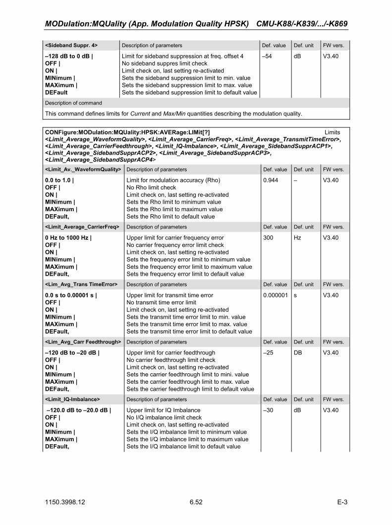
MODulation:MQUality (App. Modulation Quality HPSK) CMU-K88/-K839/.../-K869
1150.3998.12 6.52 E-3
<Sideband Suppr. 4> Description of parameters Def. value Def. unit FW vers.
–128 dB to 0 dB | OFF | ON | MINimum | MAXimum | DEFault
Limit for sideband suppression at freq. offset 4 No sideband suppres limit check Limit check on, last setting re-activated Sets the sideband suppression limit to min. value Sets the sideband suppression limit to max. value Sets the sideband suppression limit to default value
–54 dB V3.40
Description of command
This command defines limits for Current and Max/Min quantities describing the modulation quality.
CONFigure:MODulation:MQUality:HPSK:AVERage:LIMit[?] Limits <Limit_Average_WaveformQuality>, <Limit_Average_CarrierFreq>, <Limit_Average_TransmitTimeError>, <Limit_Average_CarrierFeedthrough>, <Limit_IQ-Imbalance>, <Limit_Average_SidebandSupprACP1>, <Limit_Average_SidebandSupprACP2>, <Limit_Average_SidebandSupprACP3>, <Limit_Average_SidebandSupprACP4> <Limit_Av._WaveformQuality> Description of parameters Def. value Def. unit FW vers.
0.0 to 1.0 | OFF | ON | MINimum | MAXimum | DEFault,
Limit for modulation accuracy (Rho) No Rho limit check Limit check on, last setting re-activated Sets the Rho limit to minimum value Sets the Rho limit to maximum value Sets the Rho limit to default value
0.944 –
V3.40
<Limit_Average_CarrierFreq> Description of parameters Def. value Def. unit FW vers.
0 Hz to 1000 Hz | OFF | ON | MINimum | MAXimum | DEFault,
Upper limit for carrier frequency error No carrier frequency error limit check Limit check on, last setting re-activated Sets the frequency error limit to minimum value Sets the frequency error limit to maximum value Sets the frequency error limit to default value
300 Hz V3.40
<Lim_Avg_Trans TimeError> Description of parameters Def. value Def. unit FW vers.
0.0 s to 0.00001 s | OFF | ON | MINimum | MAXimum | DEFault,
Upper limit for transmit time error No transmit time error limit Limit check on, last setting re-activated Sets the transmit time error limit to min. value Sets the transmit time error limit to max. value Sets the transmit time error limit to default value
0.000001 s V3.40
<Lim_Avg_Carr Feedthrough> Description of parameters Def. value Def. unit FW vers.
–120 dB to –20 dB | OFF | ON | MINimum | MAXimum | DEFault,
Upper limit for carrier feedthrough No carrier feedthrough limit check Limit check on, last setting re-activated Sets the carrier feedthrough limit to mini. value Sets the carrier feedthrough limit to max. value Sets the carrier feedthrough limit to default value
–25 DB V3.40
<Limit_IQ-Imbalance> Description of parameters Def. value Def. unit FW vers.
–120.0 dB to –20.0 dB | OFF | ON | MINimum | MAXimum | DEFault,
Upper limit for IQ Imbalance No I/Q imbalance limit check Limit check on, last setting re-activated Sets the I/Q imbalance limit to minimum value Sets the I/Q imbalance limit to maximum value Sets the I/Q imbalance limit to default value
–30 dB V3.40

CMU-K88/-K839/.../-K869 MODulation:MQUality (App. Modulation Quality HPSK)
1150.3998.12 6.53 E-3
<Avg. Sideband Suppr. 1 to 3> Description of parameters Def. value Def. unit FW vers.
–128 dB to 0 dB | OFF | ON | MINimum | MAXimum | DEFault,
Limit for sideband suppression at freq. offset 1, 2, or 3 No sideband suppression limit check Limit check on, last setting re-activated Sets the sideband suppression limit to min. valueSets the sideband suppression limit to max. valueSets the sideband suppression limit to default value
–43 dB V3.40
< Avg. Sideband Suppr. 4> Description of parameters Def. value Def. unit FW vers.
–128 dB to 0 dB | OFF | ON | MINimum | MAXimum | DEFault
Limit for sideband suppression at freq. offset 4 No sideband suppression limit check Limit check on, last setting re-activated Sets the sideband suppression limit to min. valueSets the sideband suppression limit to max. valueSets the sideband suppression limit to default value
–54 dB V3.40
Description of command
This command defines limits for the Average quantities describing the modulation quality.
DEFault:MODulation:MQUality:HPSK:CMMax:LIMit[?] Default Settings <Enable> <Enable> Description of parameters Def. value Def. unit FW vers.
ON | OFF
The parameters are set to their default values Some or all parameters are not set to default
ON
– V3.40
Description of command
If used as a setting command with the parameter ON, this command sets all parameters of the MODula-tion:MQUality:*:LIMit subsystem to their default values (the setting OFF results in an error message). The length of the parameter lists in the CONFigure:MODulation:MQUality...CMMax:LIMit commands is not affected.
If used as a query, the command returns whether all parameters are set to their default values (ON) or not (OFF).
The keyword CMMax refers to the Current and Max./Min. limits.
DEFault:MODulation:MQUality:HPSK:AVERage:LIMit[?] Default Settings <Enable> <Enable> Description of parameters Def. value Def. unit FW vers.
ON | OFF
The parameters are set to their default values Some or all parameters are not set to default
ON
– V3.40
Description of command
If used as a setting command with the parameter ON, this command sets all parameters of the MODula-tion:MQUality:*:LIMit subsystem to their default values (the setting OFF results in an error message). The length of the parameter lists in the CONFigure:MODulation:MQUality...AVERage:LIMit commands is not affected.
If used as a query, the command returns whether all parameters are set to their default values (ON) or not (OFF).

MODulation:MQUality (App. Modulation Quality HPSK) CMU-K88/-K839/.../-K869
1150.3998.12 6.54 E-3
Measured Values
The subsystem MODulation measures and returns the modulation parameters and compares them with the tolerance values. The subsystem corresponds to the various output elements in the measurement menu Analyzer/Generator. READ[:SCALar]:MODulation:MQUality:HPSK? Start single shot measurement and return results FETCh[:SCALar]:MODulation:MQUality:HPSK? Read out measurement results (unsynchronized) SAMPle[:SCALar]:MODulation:MQUality:HPSK? Read out measurement results (synchronized) Returned values Value range Def. value Def. unit FW vers.
AT Power (x3), Waveform Quality (Rho) (x3), Carrier Frequency Error (x3), Transmit Time Error (x3), Carrier Feedthrough (x3), I/Q Imbalance (x3), Lower Sideband Supp. 1 (x3), Upper Sideband Supp. 1 (x3) Lower Sideband Supp. 2 (x3), Upper Sideband Supp. 2 (x3) Lower Sideband Supp. 3 (x3), Upper Sideband Supp. 3 (x3) Lower Sideband Supp. 4 (x3), Upper Sideband Supp. 4 (x3), Bursts Out of Tolerance
–120.0 dBm to –33.0 dBm 0.0 to +1.0 –3000.0 Hz to +3000.0 Hz 0.0 to 0.00001 –120.0 dB to -20.0 dB –120.0 dB to –20.0 dB –120 dB to 10 dB –120 dB to 10 dB –120 dB to 10 dB –120 dB to 10 dB –120 dB to 10 dB –120 dB to 10 dB –120 dB to 10 dB –120 dB to 10 dB 0% to 100 %
NAN NAN NAN NAN NAN NAN NAN NAN NAN NAN NAN NAN NAN NAN NAN
dBm – Hz s dB dB dB dB dB dB dB dB dB dB %
V3.40
Description of command
These commands are always queries. They start a modulation measurement and output all scalar measurement results (see Chapter 4). The symbol (x3) behind a value indicates that the list contains three results corresponding to the Current, the Average, and the MMax value. Sideband Supp. 1 to Sideband Supp. 4 denotes the sideband suppression at offset frequencies 1 to 4; see command CONFig-ure:MODulation:MQUality:HPSK:CONTrol:FOFFset:SBSuppress:ACP<nr>[?].

CMU-K88/-K839/.../-K869 MODulation:MQUality (App. Modulation Quality HPSK)
1150.3998.12 6.55 E-3
CALCulate[:SCALar]:MODulation:MQUality:HPSK:MATChing:LIMIt? Limit Matching Returned values Value range Def. value Def. unit FW vers.
Waveform Quality (Rho) (x3), Carrier Frequency Error (x3), Transmit Time Error (x3), Carrier Feedthrough (x3), IQ Imbalance (x3), Lower Sideband Supp. 1 (x3), Upper Sideband Supp. 1 (x3) Lower Sideband Supp. 2 (x3), Upper Sideband Supp. 2 (x3), Lower Sideband Supp. 3 (x3), Upper Sideband Supp. 3 (x3), Lower Sideband Supp. 4 (x3), Upper Sideband Supp. 4 (x3)
For all measured values: NMAU | NMAL | INV | OK
INV INV INV INV INV INV INV INV INV INV INV INV INV
– – – – – – – – – – – – –
V3.40
Description of command
This command is always a query. It indicates whether and in which way the error limits for the scalar measured values (see above command) have been exceeded. The symbol (x3) behind a value indicates that the list contains three results corresponding to the Current, the Average, and the MMax value. Sideband Supp. 1 to Sideband Supp. 4 denotes the sideband suppression at offset frequencies 1 to 4; see command CONFigure:MODulation:MQUality:HPSK:CONTrol:FOFFset:SBSuppress:ACP<nr>[?].
The following messages may be output for all measured values:
NMAU Underflow of tolerance value not matching, underflow NMAL Tolerance value exceeded not matching, overflow INV Measurement invalid invalid OK all tolerances matched

NPOWer (Narrow Band Power) CMU-K88/-K839/.../-K869
1150.3998.12 6.56 E-3
Common Measurements and Command Groups (Signaling and Non-Signaling)
The commands for the measurement groups in this section are identical or almost identical in both test modes. Minor differences between Non-Signaling and Signaling commands are possible; they will be pointed out throughout the section.
Note: Measurements and signaling states
To perform any kind of measurement and obtain a meaningful result, an appropriate test setup is required (see application examples in chapter 2 of this manual). Consequently, if the measurements reported in this section are performed in Signaling mode, the Connected (CEST) signaling state must be reached before any of the commands retrieving test results (READ...?, FETCh...?, SAMPle...?, or CALCulate...LIMit?) can be used. Test configurations, however, can be defined any time.
NPOWer (Narrow Band Power) The subsystem NPOWer measures the Narrow Band Power using the 1xEV-DO receiver filter (according to IS-856-1). The subsystem corresponds to the NPower menu and the popup menu Power Configuration in the front panel menus.
Control of Measurement
The subsystem NPower controls the narrow band power measurement. It corresponds to the softkey NPower in the measurement menu Power. INITiate:NPOWer Start new measurement ⇒ RUN ABORt:NPOWer Abort running measurement and switch off ⇒ OFF STOP:NPOWer Stop measurement after current stat. cycle ⇒ STOP CONTinue:NPOWer Next measurement step (stepping mode) ⇒ RUN Description of command FW vers.
These commands have no query form. They start and stop the power measurement, setting it to the status indicated in the top right column.
V3.40
CONFigure:NPOWer:EREPorting[?] Event Reporting <Report Mode><Report Mode> Description of parameters Def. value Def. unit FW vers.
SRQ | SOPC | SRSQ | OFF | DEFault
Service request Single operation complete SRQ and SOPC No reporting Sets the reporting mode to the default setting
OFF – V3.40
Description of command
This command defines the events generated when the measurement is terminated or stopped (see Event Reporting in chapter 5 of the CMU 200/300 manual).

CMU-K88/-K839/.../-K869 NPOWer (Narrow Band Power)
1150.3998.12 6.57 E-3
FETCh[:SCALar]:NPOWer:STATus? Measurement Status <MeasurementStatus>, <Curr.Step.CycleCount>, <ElapsedStatistics><MeasurementStatus> Description of parameters Def. value Def. unit FW vers.
OFF | RUN | STOP | ERR | STEP | RDY
Measurement in the OFF state (*RST or ABORt) Running (after INITiate, CONTinue or READ) Stopped (STOP) OFF (could not be started) Stepping mode (<stepmode>=STEP) Stopped according to repetition mode and stop condition
OFF – V3.40
<Curr.Step.CycleCount> Description of parameters Def. value Def. unit FW vers.
1 to 10000 | NONE
Counter for current statistics cycle No counting mode set
NONE – V3.40
<ElapsedStatistics> Description of parameters Def. value Def. unit FW vers.
1 to 1000 NONE
Counter for current evaluation period within a cycle Statistic count set to off
NONE – V3.40
Description of command
This command is always a query. It returns the status of the measurement (see chapters 3 and 5).

NPOWer (Narrow Band Power) CMU-K88/-K839/.../-K869
1150.3998.12 6.58 E-3
Test Configuration
The commands of the following subsystems configure the NPower measurement in the Power menu. They correspond to the Power Configuration menu.
Subsystem CONTrol
The subsystem NPOWer:CONTrol defines the repetition mode and statistic count of the measurement. CONFigure:NPOWer:CONTrol[?] Scope of Measurement <Statistics>, <Repetition>, <Stop Condition>, <Step Mode><Statistics> Description of parameters Def. value Def. unit FW vers.
1 to 1000 | MINimum | MAXimum | DEF,
Number of bursts per statistics cycle Sets the value to the range minimum Sets the value to the range maximum Sets the value to the default setting
100 – V3.40
<Repetition> Description of parameters Def. value Def. unit FW vers.
1 to 10000 | CONTinuous | SINGleshot | DEFault,
Multiple measurement (counting, until Status = STEP | RDY) Continuous measurement (until STOP or ABORT) Single shot measurement (until Status = RDY) Sets the value to the default setting
SING – V3.40
<Stop Condition> Description of parameters Def. value Def. unit FW vers.
NONE | SON,
Continue measurement even in case of error Stop measurement in case of error (stop on error)
NONE – V3.40
<Step Mode> Description of parameters Def. value Def. unit FW vers.
NONE | STEP
Continue measurement according to its rep. mode Interrupt measurement after each statistics cycle
NONE – V3.40
Description of command
This command combines the ...CONTrol:STATistics and the ...CONTrol:REPetition commands
CONFigure:NPOWer:CONTrol:STATistics[?] Statistic Count <Statistics><Statistics> Description of parameters Def. value Def. unit FW vers.
1 to 1000 | MINimum | MAXimum | DEF
Number of bursts per statistics cycle Sets the value to the range minimum Sets the value to the range maximum Sets the value to the default setting
100 – V3.40
Description of command
This command specifies the type of measured values and defines the number of bursts forming a statistics cycle.

CMU-K88/-K839/.../-K869 NPOWer (Narrow Band Power)
1150.3998.12 6.59 E-3
CONFigure:NPOWer:CONTrol:REPetition[?] Test Cycles <Repetition>, <Stop Condition>, <Step Mode><Repetition> Description of parameters Def. value Def. unit FW vers.
1 to 10000 | CONTinuous | SINGleshot | DEFault,
Multiple measurement (counting, until Status = STEP | RDY) Continuous measurement (until STOP or ABORT) Single shot measurement (until Status = RDY) Sets the value to the default setting
SING – V3.40
<Stop Condition> Description of parameters Def. value Def. unit FW vers.
NONE | SONerror | DEFault,
Continue measurement even in case of error Stop measurement in case of error (stop on error) Default value
NONE – V3.40
<Step Mode> Description of parameters Def. value Def. unit FW vers.
NONE | STEP | DEFault
Continue measurement according to its rep. mode Interrupt measurement after each statistics cycle Default value
NONE – V3.40
Description of command
This command determines the number of statistics cycles for the measurement.
Note: In the case of READ commands (READ:...), the <Repetition> parameter has no effect; the measurement is always stopped after a single shot.
Measured Values
The subsystem NPOWer determines and returns the results of the Narrow Band Power measurements. XTND:NPOWer:RESult:NBANd[?] <Enable> Scope of scalar results <Static results extension> <Enable> Description of parameters Def. value Def. unit FW vers.
ON | OFF | DEFault
Statistical results returned No statistical results returned The scalar narrow band power results are set to default
OFF
– V3.40
Description of command
This command qualifies whether or not READ[:SCALar]:NPOWer?, FETCh…?, SAMPle…? return the statistical power results for 1.23 MHz.
If used as a query, the command returns whether all parameters are set to their default values (ON) or not (OFF).

SAPPower (Standby and Access Probe Power) CMU-K88/-K839/.../-K869
1150.3998.12 6.60 E-3
Scalar results: READ[:SCALar]:NPOWer? Start single shot measurement and return results FETCh[:SCALar]:NPOWer? Read out measurement results (unsynchronized) SAMPle[:SCALar]:NPOWer? Read out measurement results (synchronized) Returned values Description Def. value Def. unit FW vers.
Avg. Power of Current evaluation period, Min. Power of Current evaluation period, Max. Power of Current evaluation period, Avg. Power referenced to a stat. cycle, Min. Power of the entire measurement, Max. Power of the entire measurement Avg. Power of curr. eval. period @1.23 MHz,Min. Power of curr. eval. period @1.23 MHz,Max. Power of curr.eval. period @1.23 MHz, Avg. Power ref.to a stat. cycle @1.23 MHz, Min. Power of the entire meas. @1.23 MHz, Max. Power of the entire meas. @1.23 MHz
–137 dBm to +53 dBm –137 dBm to +53 dBm –137 dBm to +53 dBm –137 dBm to +53 dBm –137 dBm to +53 dBm –137 dBm to +53 dBm –137 dBm to +53 dBm –137 dBm to +53 dBm –137 dBm to +53 dBm –137 dBm to +53 dBm –137 dBm to +53 dBm –137 dBm to +53 dBm
NAN dBm dBm dBm dBm dBm dBm dBm dBm dBm dBm dBm dBm
V3.40
V4.31
Description of command
These commands are always queries. They start a measurement and output all scalar measurement results.
Note: The @1.23 MHz values are returned only if XTND:NPOWer:RESult:NBANd is set to ON.
SAPPower (Standby and Access Probe Power) The subsystem SAPPower contains the commands for measuring the standby and access probe power. It corresponds to the softkey Power of the tab Connection in the menu group Connect. Control.
INITiate:SAPPower Start new measurement ⇒ RUN ABORt:SAPPower Abort running measurement and switch off ⇒ OFF STOP:SAPPower Stop measurement after current stat. cycle ⇒ STOP CONTinue:SAPPower Next measurement step (stepping mode) ⇒ RUN Description of command Sig. State FW vers.
These commands have no query form. They start or stop the measurement, setting it to the status given in the top right column.
SON / SOP
V4.31
CONFigure:SAPPower:EREPorting[?] Event Reporting <Report Mode>
<Report Mode> Description of parameters Def. value Def. unit FW vers.
SRQ | SOPC | SRSQ | OFF
Service request Single operation complete SRQ and SOPC No reporting
OFF – V4.31
Description of command Sig. State
This command defines the events generated when the measurement is terminated or stopped (event reporting, see chapter 5).
all

CMU-K88/-K839/.../-K869 MODulation:OVERview
1150.3998.12 6.61 E-3
FETCh[:SCALar]:SAPPower:STATus? <Measurement Status>, <Statistic Count><Measurement Status> Description of parameters Def. value Def. unit
OFF | RUN | STOP | ERR | STEP | RDY
Measurement in the OFF state (*RST or ABORt)Running (after INITiate, CONTinue or READ)Stopped (STOP)OFF (could not be started) Stepping mode (<stepmode>=STEP) Stopped according to repetition mode and stop condition
OFF
–
<Statistic Count> Description of parameters Def. value Def. unit FW vers.
1 to 10000 | NONE
Counter for current statistics cycle No counting mode set
OFF
V4.31
Description of command Sig. State
This command is always a query. It returns the status of the measurement (see chapters 3 and 5). SON / SOP
Scalar Results: READ[:SCALar]:SAPPower? Start single shot measurement and return results FETCh[:SCALar]:SAPPower? Read out measurement results (unsynchronized) SAMPle[:SCALar]:SAPPower? Read out measurement results (synchronized) <Standby Power>, <Access Probe Power><Standby Power> Description of parameters Def. value Def. unit FW vers.
–137 dBm to +44 dBm Standby power NAN dBm V4.31
<Access Probe Power> Description of parameters Def. value Def. unit
–137 dBm to +44 dBm Access probe power NAN dBm
Description of command Sig. State
These commands are always queries. They start the measurement of the standby and access probe power and output the result.
SON / SOP
MODulation:OVERview The subsystem MODulation:OVERview measures general scalar modulation parameters of the AT transmitter output signal. The subsystem corresponds to the measurement menu Modulation and the associated popup menu Modulation Configuration.
Control of Measurement
The subsystem MODulation:OVERview controls the modulation overview measurement. It corresponds to the softkey Overview HPSK in the measurement menu Modulation.
INITiate:MODulation:OVERview:HPSK Start new measurement ⇒ RUN ABORt:MODulation:OVERview:HPSK Abort running measurement and switch off ⇒ OFF STOP:MODulation:OVERview:HPSK Stop measurement after current stat. cycle ⇒ STOP CONTinue:MODulation:OVERview:HPSK Next measurement step (stepping mode) ⇒ RUN Description of command FW vers.
These commands have no query form. They start and stop the modulation overview measurement, setting it to the status indicated in the top right column.
V3.40

MODulation:OVERview CMU-K88/-K839/.../-K869
1150.3998.12 6.62 E-3
CONFigure:MODulation:OVERview:HPSK:EREPorting[?] Event Reporting <Report Mode><Report Mode> Description of parameters Def. value Def. unit FW vers.
SRQ | SOPC | SRSQ | OFF | DEFault
Service request Single operation complete SRQ and SOPC No reporting Sets the value to the default setting
OFF – V3.40
Description of command
This command defines the events generated when the measurement is terminated or stopped (see Event Reporting in chapter 5 of the CMU 200/300 manual).
FETCh[:SCALar]:MODulation:OVERview:HPSK:STATus? Measurement Status <HPSK_MeasurementStatus>, <Curr.Step.CycleCount>, <ElapsedStatistics> <HPSK_Meas.Status> Description of parameters Def. value Def. unit FW vers.
OFF | RUN | STOP | ERR | STEP | RDY,
Measurement in the OFF state (*RST or ABORt) Running (after INITiate, CONTinue or READ) Stopped (STOP) OFF (could not be started) Stepping mode (<stepmode>=STEP) Stopped according to repetition mode and stop condition
OFF
– V3.40
<Curr.Step.CycleCnt> Description of parameters Def. value Def. unit FW vers.
1 to 10000 | NONE,
Counter for current statistics cycle No counting mode set
NONE – V3.40
<ElapsedStatistics> Description of parameters Def. value Def. unit FW vers.
1 to 1000 NONE
Counter for current evaluation period within a cycle Statistic count set to off
NONE – V3.40
Description of command
This command is always a query. It returns the status of the measurement (see chapters 3 and 5).

CMU-K88/-K839/.../-K869 MODulation:OVERview
1150.3998.12 6.63 E-3
Test Configuration
The commands of the following subsystems configure the Modulation Overview measurement in the Modulation menu. They correspond to the Modulation Overview Configuration menu.
Subsystem CONTrol
The subsystem MODulation:OVERview:CONTrol configures the modulation overview measurement. It corresponds to the Control tab in the popup menu Modulation Configuration.
DEFault:MODulation:OVERview:HPSK:CONTrol[?] Default Settings <Enable><Enable> Description of parameters Def. value Def. unit FW vers.
ON | OFF
The parameters are set to their default values Some or all parameters are not set to default
ON
– V3.40
Description of command
If used as a setting command with the parameter ON, this command sets all parameters of the subsystem MODulation:OVERview:….:CONTrol to their default values (the setting OFF results in an error message).
If used as a query, the command returns whether all parameters are set to their default values (ON) or not (OFF).
CONFigure:MODulation:OVERview:HPSK:CONTrol[?] Scope of Measurement <Statistic Count>, <Repetition>, <Stop Cond>, <Step Mode><Statistic Count> Description of parameters Def. value Def. unit FW-Vers.
1 to 1000, Number of bursts per statistics cycle 100 – V3.40
<Repetition> Description of parameters Def. value Def. unit FW-Vers.
1 to 10000 | CONTinuous | SINGleshot | DEFault,
Multiple measurement (counting, until Status = STEP | RDY) Continuous measurement (until STOP or ABORT) Single shot measurement (until Status = RDY) Sets the value to the default setting
SING – V3.40
<Stop Cond> Description of parameters Def. value Def. unit FW-Vers.
NONE | SONerror | DEFault,
Continue measurement even in case of error Stop measurement in case of error (stop on error) Sets the value to the default setting
NONE – V3.40
<Step Mode> Description of parameters Def. value Def. unit FW-Vers.
STEP | NONE | DEFault
Interrupt measurement after each statistics cycle Continue measurement according to its rep. Mode Sets the value to the default setting
NONE – V3.40
Description of command
This command combines the ...CONTrol:STATistics and the ...CONTrol:REPetition commands, see below.

MODulation:OVERview CMU-K88/-K839/.../-K869
1150.3998.12 6.64 E-3
CONFigure:MODulation:OVERview:HPSK:CONTrol:STATistics[?] Statistic Count <Statistic Count><Statistic Count> Description of parameters Def. value Def. unit FW-Vers.
1 to 1000 Number of bursts per statistics cycle 100 – V3.40
Description of command
This command specifies the type of measured values and defines the number of bursts forming a statistics cycle.
CONFigure:MODulation:OVERview:HPSK:CONTrol:REPetition[?] Test Cycles <Repetition>, <Stop Cond>, <Step Mode> <Repetition> Description of parameters Def. value Def. unit FW vers.
1 to 10000 | CONTinuous | SINGleshot | DEFault
Multiple measurement (counting, until Status = STEP | RDY) Continuous measurement (until STOP or ABORT) Single shot measurement (until Status = RDY) Sets the value to the default setting
SING – V3.40
<Stop Cond> Description of parameters Def. value Def. unit FW vers.
NONE | SONerror | DEFault
Continue measurement even in case of error Stop measurement in case of error (stop on error) Sets the value to the default setting
NONE – V3.40
<Step Mode> Description of parameters Def. value Def. unit FW vers.
STEP | NONE | DEFault
Interrupt measurement after each statistics cycle Continue measurement according to its rep. Mode Sets the value to the default setting
NONE – V3.40
Description of command
This command determines the repetition mode, stop condition, and stepping mode for the measurement.
Note: In the case of READ commands (READ:...), the <Repetition> parameter has no effect; the measurement is always stopped after a single shot.

CMU-K88/-K839/.../-K869 MODulation:OVERview
1150.3998.12 6.65 E-3
Subsystem LIMit
The subsystem MODulation:OEMP:...:LIMit defines the tolerance values for the scalar results of the following modulation measurements (OEMP): • Overview • Error Vector Magnitude • Magnitude Error • Phase Error. The subsystem corresponds to the Limits tab in the popup menu Modulation Quality Configuration. Different limits can be configured for the the Current and Max./Min. traces. CONFigure:MODulation:OEMP:HPSK:CMMax:LIMit[:SCALar]:SYMMetric[:COMBined][?] Limits <Limit_Peak_EVM>, <Enable>, <Limit_RMS_EVM>, <Enable>, <Limit_Peak_ME>, <Enable>, <Limit_RMS_ME>, <Enable>, <Limit_Peak_PE>, <Enable>, <Limit_RMS_PE>, <Enable>, <Carrier_Feedthrough_Limit>, <Enable>, <IQ_Imbalance_Limit>, <Enable>, <Carrier_Freq_Error_Limit>, <Enable>, <Tx_Time_Error_Limit>, <Enable>, <WFM_Quality_Limit>, <Enable> <Enable> Description of parameters Def. value Def. unit FW vers.
ON | OFF Switch limit check for parameter preceding <Enable> on or off
ON – V3.40
Parameters Description of parameters Def. value Def. unit FW vers.
0.0 % to +100.0 %, 0.0 % to +100.0 %, 0.0 % to +100.0 %, 0.0 % to +100.0 %, 0.0 deg to 180.0 deg, 0.0 deg to 180.0 deg, –120.0 dB to –20.0 dB, –120.0 dB to –20.0 dB, 0 Hz to 1000 Hz, 0.0 µs to 10.0 µs, 0.0 to 1.0
(EVM) Error Vector Magnitude Error Peak (EVM) Error Vector Magnitude Error RMS (ME) Magnitude Error Peak (ME) Magnitude Error RMS (PE) Phase Error Peak (PE) Phase Error RMS Carrier Feedthrough I/Q Imbalance Carrier Frequency Error Transmit Time Error Limit for waveform quality (modulation accuracy, Rho)
33.4 23.6 33.4 23.6 OFF OFF –25.0 –30.0 300 0.000001
0.944
%%%%deg deg dB dB Hz s–
V3.40
Description of command
This command defines upper limits for the different traces and for the scalar modulation parameters derived from them. The keyword CMMax refers to the Current and Max./Min. traces. After each parameter definition, the limit check for this parameter can be enabled or disabled.
Limit definition and enabling of the limit check can be done separately.

MODulation:OVERview CMU-K88/-K839/.../-K869
1150.3998.12 6.66 E-3
CONFigure:MODulation:OEMP:HPSK:AVERage:LIMit[:SCALar]:SYMMetric[:COMBined][?] Limits <Limit_Peak_EVM>, <Enable>, <Limit_RMS_EVM>, <Enable>, <Limit_Peak_ME>, <Enable>, <Limit_RMS_ME>, <Enable>, <Limit_Peak_PE>, <Enable>, <Limit_RMS_PE>, <Enable>, <Carrier_Feedthrough_Limit>, <Enable>, <IQ_Imbalance_Limit>, <Enable>, <Carrier_Freq_Error_Limit>, <Enable>, <Tx_Time_Error_Limit>, <Enable>, <WFM_Quality_Limit>, <Enable><Enable> Description of parameters Def. value Def. unit FW vers.
ON | OFF, Switch limit check for parameter preceding <Enable> on or off
ON – V3.40
Parameters Description of parameters Def. value Def. unit FW vers.
0.0 % to +100.0 %, 0.0 % to +100.0 %, 0.0 % to +100.0 %, 0.0 % to +100.0 %, 0.0 deg to 180.0 deg, 0.0 deg to 180.0 deg, –120.0 dB to –20.0 dB, –120.0 dB to –20.0 dB, 0 Hz to 1000 Hz, 0.0 µs to 10.0 µs, 0.0 to 1.0
(EVM) Error Vector Magnitude Error Peak (EVM) Error Vector Magnitude Error RMS (ME) Magnitude Error Peak (ME) Magnitude Error RMS (PE) Phase Error Peak (PE) Phase Error RMS Carrier Feedthrough I/Q Imbalance Carrier Frequency Error Transmit Time Error Limit for waveform quality (modulation accuracy, Rho)
33.4 23.6 33.4 23.6 19.6 13.6 –25.0 –30.0 300 0.000001
0.944
%%%%deg deg dB dB Hz s–
V3.40
Description of command
This command defines upper limits for the different traces and for the scalar modulation parameters derived from them. The keyword AVERage refers to the Average trace. After each parameter definition, the limit check for this parameter can be enabled or disabled.
Limit definition and enabling of the limit check can be done separately.
Limit values CONFigure:MODulation:OEMP:HPSK:CMMax:LIMit[:SCALar]:SYMMetric[:COMBined]:VALue[?] <Limit_Peak_EVM>, <Limit_RMS_EVM>, <Limit_Peak_ME>, <Limit_RMS_ME>, <Limit_Peak_PE>, <Limit_RMS_PE>, <Carrier_Feedthrough_Limit>, <IQ_Imbalance_Limit>, <Carrier_Freq_Error_Limit>, <Tx_Time_Error_Limit>, <WFM_Quality_Limit> Parameter Description of parameters Def. value Def. unit FW vers.
0.0 % to +100.0 %, 0.0 % to +100.0 %, 0.0 % to +100.0 %, 0.0 % to +100.0 %, 0.0 deg to 180.0 deg, 0.0 deg to 180.0 deg, –120.0 dB to –20.0 dB, –120.0 dB to –20.0 dB, 0 Hz to 1000 Hz, 0.0 µs to 10.0 µs, 0.0 to 1.0
(EVM) Error Vector Magnitude Error Peak (EVM) Error Vector Magnitude Error RMS (ME) Magnitude Error Peak (ME) Magnitude Error RMS (PE) Phase Error Peak (PE) Phase Error RMS Carrier Feedthrough I/Q Imbalance Carrier Frequency Error Transmit Time Error Limit for waveform quality (modulation accuracy, Rho)
33.4 23.6 33.4 23.6 OFF OFF –25.0 –30.0 300 0.0000010.944
%%%%deg deg dB dB Hz s–
V3.40
Description of command
This command defines upper limits for the different traces and for the scalar modulation parameters derived from them. The keyword CMMax refers to the Current and Max./Min. traces.

CMU-K88/-K839/.../-K869 MODulation:OVERview
1150.3998.12 6.67 E-3
Limit values CONFigure:MODulation:OEMP:HPSK:AVERage:LIMit[:SCALar]:SYMMetric[:COMBined]:VALue[?] <Limit_Peak_EVM>, <Limit_RMS_EVM>, <Limit_Peak_ME>, <Limit_RMS_ME>, <Limit_Peak_PE>, <Limit_RMS_PE>, <Carrier_Feedthrough_Limit>, <IQ_Imbalance_Limit>, <Carrier_Freq_Error_Limit>, <Tx_Time_Error_Limit>, <WFM_Quality_Limit> Parameter Description of parameters Def. value Def. unit FW vers.
0.0 % to +100.0 %, 0.0 % to +100.0 %, 0.0 % to +100.0 %, 0.0 % to +100.0 %, 0.0 deg to +45.0 deg, 0.0 deg to +45.0 deg, –120.0 dB to –20.0 dB, –120.0 dB to –20.0 dB, 0 Hz to 1000 Hz, 0.0 µs to 10.0 µs, 0.0 to 1.0
(EVM) Error Vector Magnitude Error Peak (EVM) Error Vector Magnitude Error RMS (ME) Magnitude Error Peak (ME) Magnitude Error RMS (PE) Phase Error Peak (PE) Phase Error RMS Carrier Feedthrough I/Q Imbalance Carrier Frequency Error Transmit Time Error Limit for waveform quality (modulation accuracy, Rho)
33.4 23.6 33.4 23.6 19.6 13.6 –25.0 –30.0 300 0.000001
0.944
%%%%deg deg dB dB Hz s–
V3.40
Description of command
This command defines upper limits for the different traces and for the scalar modulation parameters derived from them. The keyword AVERage refers to the Average trace.
Limit Enable CONFigure:MODulation:OEMP:HPSK:CMMax:LIMit[:SCALar]:SYMMetric[:COMBined]:ENABle[?] <Limit_Peak_EVM>, <Limit_RMS_EVM>, <Limit_Peak_ME>, <Limit_RMS_ME>, <Limit_Peak_PE>, <Limit_RMS_PE>, <Carrier_Feedthrough_Limit>, <IQ_Imbalance_Limit>, <Carrier_Freq_Error_Limit>, <Tx_Time_Error_Limit>, <WFM_Quality_Limit> <Enable> Description of parameters Def. value Def. unit FW vers.
ON | OFF Switch limit check for corresponding parameter on or off. ON (see below)
– V3.40
Description of command
This command enables or disables the limit check for the different traces and for the scalar modulation parameters derived from them. The keyword CMMax refers to the Current and Max./Min. traces.
Note: The default value is ON for all limits execept the phase error limits (Def. Value = OFF).
Limit Enable CONFigure:MODulation:OEMP:HPSK:AVERage:LIMit[:SCALar]:SYMMetric[:COMBined]:ENABle[?] <Limit_Peak_EVM>, <Limit_RMS_EVM>, <Limit_Peak_ME>, <Limit_RMS_ME>, <Limit_Peak_PE>, <Limit_RMS_PE>, <Carrier_Feedthrough_Limit>, <IQ_Imbalance_Limit>, <Carrier_Freq_Error_Limit>, <Tx_Time_Error_Limit>, <WFM_Quality_Limit> <Enable> Description of parameters Def. value Def. unit FW vers.
ON | OFF Switch limit check for corresponding parameter on or off. ON – V3.40
Description of command
This command enables or disables the limit check for the different traces and for the scalar modulation parameters derived from them. The keyword AVERage refers to the Average trace.

MODulation:OVERview CMU-K88/-K839/.../-K869
1150.3998.12 6.68 E-3
DEFault:MODulation:OEMP:HPSK:LIMit[?] Default Settings <Enable> <Enable> Description of parameters Def. value Def. unit FW vers.
ON | OFF
The parameters are set to their default values Some or all parameters differ from their default values
ON
– V3.40
Description of command
If used as a setting command with the parameter ON, this command sets all parameters of the subsystem MODulation:OEMP:LIMit to their default values (the setting OFF results in an error message). If used as a query the command returns whether all parameters are set to their default values (ON) or not (OFF).
Measured Values
The subsystem MODulation:OVERview measures and returns the modulation overview parameters and compares them with the tolerance values. The subsystem corresponds to the various output elements in the measurement menu MODulation, application Overview.
Scalar Results READ[:SCALar]:MODulation:OVERview:HPSK? Start single shot measurement and return results FETCh[:SCALar]:MODulation:OVERview:HPSK? Read out meas. results (unsynchronized) SAMPle[:SCALar]:MODulation:OVERview:HPSK? Read out measurement results (synchronized) Returned values Value range Def. value Def. unit FW vers.
EVM Peak (x3), EVM RMS (x3), Magn. Error Peak (x3), Magn. Error RMS (x3), Phase Error Peak (x3), Phase Error RMS (x3), Carrier Feedthrough (x3), I/Q Imbalance (x3), Carrier Freq. Error (x3), Tx Time Error (x3), Waveform Quality (Rho) (x3), AT Power (x3), Current Statistics, Bursts Out Of Tolerance
0.0 % to 100.0 % 0.0 % to 100.0 % 0.0 % to 100.0 % 0.0 % to 100.0 % 0.0 deg to +45.0 deg 0.0 deg to +45.0 deg –120.0 dB to –20.0 dB –120.0 dB to –20.0 dB 0 Hz to 1000 Hz 0 µs to 10 µs0 to 1 –133.0 dBm to +19.0 dBm 1 to 1000 0.0 % to 100.0 %
NAN NAN NAN NAN NAN NAN
NAN NAN NAN NAN NAN NAN NAN NAN
%%%%deg deg dB dB Hz µs–dB –%
V3.40
Description of command
These commands are always queries. They start a modulation overview measurement and output all scalar measurement results (see chapter 4). The calculation of results in an average or peak measurement is described in chapter 3 (see calculation of statistical quantities). The symbol (x3) behind a value indicates that the list contains three results corresponding to the Current, the Average, and the MMax value.

CMU-K88/-K839/.../-K869 MODulation:EVMagnitude (Error Vector Magnitude)
1150.3998.12 6.69 E-3
CALCulate[:SCALar]:MODulation:OVERview:HPSK:MATChing:LIMit? Limit Matching
Returned values Value range Def. value Def. unit FW vers.
EVM Peak (x3), EVM RMS (x3), Magn. Error Peak (x3), Magn. Error RMS (x3), Phase Error Peak (x3), Phase Error RMS (x3), Carrier Feedthrough (x3), I/Q Imbalance (x3), Carrier Freq. Error (x3), Tx Time Error (x3), Waveform Quality (Rho) (x3), AT Power (x3)
For all measured values: NMAU | NMAL | INV | OK
INV INV INV INV INV INV INV INV INV INV INV INV
––––––––––––
V3.40
Description of command
This command is always a query. It indicates whether and in which way the error limits for the scalar measured values (see above command) have been exceeded. The symbol (x3) behind a value indicates that the list contains three results corresponding to the Current, the Average, and the MMax value.
The following messages may be output for all measured values:
NMAU Underflow of tolerance value not matching, underflow NMAL Tolerance value exceeded not matching, overflow INV Measurement invalid invalid OK all tolerances matched
MODulation:EVMagnitude (Error Vector Magnitude)
The subsystem MODulation:EVMagnitude measures the error vector magnitude as well as general scalar modulation parameters. The subsystem corresponds to the measurement menu Modulation, application EVM H-PSK, and the associated popup menu Modulation Configuration.
Control of Measurement
The subsystem MODulation:EVMagnitude controls the error vector magnitude measurement. It corresponds to the softkey EVM H-PSK in the measurement menu Modulation.
INITiate:MODulation:EVMagnitude:HPSK Start new measurement ⇒ RUN ABORt:MODulation:EVMagnitude:HPSK Abort running measurement and switch off ⇒ OFF STOP:MODulation:EVMagnitude:HPSK Stop measurement after current stat. cycle ⇒ STOP CONTinue:MODulation:EVMagnitude:HPSK Next measurement step (stepping mode) ⇒ RUN Description of command FW vers.
These commands have no query form. They start and stop the error vector magnitude measurement, setting it to the status indicated in the top right column.
V3.40

MODulation:EVMagnitude (Error Vector Magnitude) CMU-K88/-K839/.../-K869
1150.3998.12 6.70 E-3
CONFigure:MODulation:EVMagnitude:HPSK:EREPorting[?] Event Reporting <Report Mode><Report Mode> Description of parameters Def. value Def. unit FW vers.
SRQ | SOPC | SRSQ | OFF | DEFault
Service request Single operation complete SRQ and SOPC No reporting Sets the value to the default setting
OFF – V3.40
Description of command
This command defines the events generated when the measurement is terminated or stopped (see Event Reporting in chapter 5 of the CMU 200/300 manual).
FETCh[:SCALar]:MODulation:EVMagnitude:HPSK:STATus? Measurement Status <HPSK_MeasurementStatus>, <Curr.Step.CycleCount>, <ElapsedStatistics> <Meas. Status> Description of parameters Def. value Def. unit FW vers.
OFF | RUN | STOP | ERR | STEP | RDY
Measurement in the OFF state (*RST or ABORt) Running (after INITiate, CONTinue or READ) Stopped (STOP) OFF (could not be started) Stepping mode (<stepmode>=STEP) Stopped according to repetition mode and stop condition
OFF – V3.40
<Cycle Count> Description of parameters Def. value Def. unit FW vers.
1 to 10000 | NONE
Counter for current statistics cycle No counting mode set
NONE – V3.40
<ElapsedStatistics> Description of parameters Def. value Def. unit FW vers.
1 to 1000 | NONE
Counter for current evaluation period within a cycle Statistic count set to off
NONE – V3.40
Description of command
This command is always a query. It returns the status of the measurement (see chapters 3 and 5).

CMU-K88/-K839/.../-K869 MODulation:EVMagnitude (Error Vector Magnitude)
1150.3998.12 6.71 E-3
Test Configuration
The commands of the following subsystems configure the Error Vector Magnitude measurement in the Modulation menu. They correspond to the Modulation Configuration menu. Subsystem CONTrol
The subsystem MODulation:EVMagnitude:CONTrol configures the error vector magnitude measurement. It corresponds to the Control tab in the popup menu Modulation Configuration.
CONFigure:MODulation:EVMagnitude:HPSK:CONTrol[?] Scope of Measurement <Statistics Count>, <Repetition>, <Stop Cond>, <Step Mode> <Result Mode> Description of parameters Def. value Def. unit FW-Vers.
SCALar | ARRay,
Scalar values only (incl. ramp matching) Scalar measured values and arrays
ARR – V3.40
<Statistics Count> Description of parameters Def. value Def. unit FW-Vers.
1 to 1000, Number of bursts per statistics cycle 100 – V3.40
<Repetition> Description of parameters Def. value Def. unit FW-Vers.
1 to 10000 | CONTinuous | SINGleshot | DEFault,
Multiple measurement (counting, until Status = STEP | RDY) Continuous measurement (until STOP or ABORT) Single shot measurement (until Status = RDY) Sets the value to the default setting
SING – V3.40
<Stop Cond> Description of parameters Def. value Def. unit FW-Vers.
NONE | SONerror | DEFault,
Continue measurement even in case of error Stop measurement in case of error (stop on error) Sets the value to the default setting
NONE – V3.40
<Step Mode> Description of parameters Def. value Def. unit FW-Vers.
STEP | NONE | DEFault
Interrupt measurement after each statistics cycle Continue measurement according to its rep. mode Sets the value to the default setting
NONE – V3.40
Description of command
This command combines the ....CONTrol:STATistics and ...CONTrol:REPetition commands, see below.
CONFigure:MODulation:EVMagnitude:HPSK:CONTrol:RMODe[?] Result mode <Result Mode> <Result Mode> Description of parameters Def. value Def. unit FW-Vers.
SCALar | ARRay
Scalar values only (incl. ramp matching) Scalar measured values and arrays
ARR – V3.40
Description of command
This command specifies the type of measured values.
CONFigure:MODulation:EVMagnitude:HPSK:CONTrol:STATistics[?] Statistics Count <Statistics Count><Statistics Count> Description of parameters Def. value Def. unit FW-Vers.
1 to 1000 Number of bursts per statistics cycle 100 – V3.40
Description of command
This command specifies the type of measured values and defines the number of bursts forming a statistics cycle.

MODulation:EVMagnitude (Error Vector Magnitude) CMU-K88/-K839/.../-K869
1150.3998.12 6.72 E-3
CONFigure:MODulation:EVMagnitude:HPSK:CONTrol:REPetition[?] Test Cycles <Repetition> ,<Stop Cond>, <Step Mode><Repetition> Description of parameters Def. value Def. unit FW vers.
1 to 10000 | CONTinuous | SINGleshot | DEFault,
Multiple measurement (counting, until Status = STEP | RDY) Continuous measurement (until STOP or ABORT) Single shot measurement (until Status = RDY) Sets the value to the default setting
SING – V3.40
<Stop Cond> Description of parameters Def. value Def. unit FW vers.
NONE | SONerror | DEFault,
Continue measurement even in case of error Stop measurement in case of error (stop on error) Sets the value to the default setting
NONE – V3.40
<Step Mode> Description of parameters Def. value Def. unit FW vers.
STEP | NONE | DEFault
Interrupt measurement after each statistics cycle Continue measurement according to its rep. mode Sets the value to the default setting
NONE – V3.40
Description of command
This command determines the repetition mode, stop condition, and stepping mode for the measurement.
Note: In the case of READ commands (READ:...), the <Repetition> parameter has no effect; the measurement is always stopped after a single shot.
DEFault:MODulation:EVMagnitude:HPSK:CONTrol[?] Default Settings <Enable><Enable> Description of parameters Def. value Def. unit FW vers.
ON | OFF
The parameters are set to their default values Some or all parameters are not set to default
ON
– V3.40
Description of command
If used as a setting command with the parameter ON, this command sets all parameters of the subsystem MODulation:EVMagnitude:….:CONTrol to their default values (the setting OFF results in an error message).
If used as a query, the command returns whether all parameters are set to their default values (ON) or not (OFF).

CMU-K88/-K839/.../-K869 MODulation:EVMagnitude (Error Vector Magnitude)
1150.3998.12 6.73 E-3
Subsystem LIMit
The subsystem MODulation:OEMP:...:LIMit (refer to page 6.65) defines the tolerance values for the OEMP modulation measurements. The subsystem corresponds to the Modulation section in the Limits tab in the popup menu Modulation Configuration.
Subsystem SUBarrays
The subsystem SUBarrays:MODulation defines the measurement range and the type of output values. CONFigure:SUBarrays:MODulation:EVMagnitude:HPSK[?] Definition of Subarrays <Mode>, <Start>, <Samples><Mode> Description of parameters Def. value Def. unit FW vers.
ALL | ARIThmetical | MINimum | MAXimum
Return all measurement values Return arithm. mean value in every range Return minimum value in every range Return maximum value in every range
ALL – V3.40
<Start> Description of parameters Def. value Def. unit FW vers.
0 µs to 833 µs Start time in current range NAN s V3.40
<Samples> Description of parameters Def. value Def. unit FW vers.
0 to 1024 Number of samples in current range NAN – V3.40
Description of command
This command configures the READ:SUBarrays..., FETCh:SUBarrays..., and SAMPle:SUBarrays:MODulation:EVMagnitude commands. It restricts the measurement to up to 32 subranges where either all measurement results (the number of which is given by the second numerical parameter) or a single statistical value is returned. The subranges are defined by the start time and the number of test points which are located on a fixed, equidistant grid with a step width of 1 symbol period.
The subranges may overlap but must be within the total range of the Modulation measurement. Test points outside this range are not measured (result NAN) and do not enter into the ARIThmetical, MINimum and MAXimum values.
By default, only one range corresponding to the total measurement range is used and all measurement values are returned.

MODulation:EVMagnitude (Error Vector Magnitude) CMU-K88/-K839/.../-K869
1150.3998.12 6.74 E-3
Measured Values
The subsystem MODulation:EVMagnitude measures and returns the error vector magnitude results and compares them with the tolerance values. The subsystem corresponds to the various output elements in the measurement menu MODulation, application Error Vector Magnitude.
Scalar Results READ[:SCALar]:MODulation:EVMagnitude:HPSK? Start single shot measurement and return results FETCh[:SCALar]:MODulation:EVMagnitude:HPSK? Read out meas. results (unsynchronized) SAMPle[:SCALar]:MODulation:EVMagnitude:HPSK? Read out measurement results (synchronized) Returned values Value range Def. value Def. unit FW vers.
EVM Peak (x3), EVM RMS (x3), Carrier Feedthrough (x3), I/Q Imbalance (x3), Carrier Freq. Error (x3), Tx Time Error (x3), Waveform Quality (Rho) (x3), AT Power (x3), Current Statistics, Bursts Out Of Tolerance
0.0 % to 100.0 % 0.0 % to 100.0 % –120.0 dB to –20.0 dB –120.0 dB to –20.0 dB 0 Hz to 1000 Hz 0 µs to 10 µs0 to 1 –133.0 dBm to +19.0 dBm 1 to 1000 0.0 % to 100.0 %
NAN NAN NAN NAN NAN NAN NAN NAN NAN NAN
%%
dB dB Hz µs–dB –%
V3.40
Description of command
These commands are always queries. They start a EVM measurement and output the scalar measurement results (see chapter 4). The calculation of results in an average or peak measurement is described in chapter 3 (see calculation of statistical quantities). The symbol (x3) behind a value indicates that the list contains three results corresponding to the Current, the Average, and the MMax value.
CALCulate[:SCALar]:MODulation:EVMagnitude:HPSK:MATChing:LIMit? Out of Tolerance
Returned values Value range Def. value Def. unit FW vers.
EVM Peak (x3), EVM RMS (x3), Carrier Feedthrough (x3), I/Q Imbalance (x3), Carrier Freq. Error (x3), Tx Time Error (x3), Waveform Quality (Rho) (x3), AT Power (x3)
For all measured values: NMAU | NMAL | INV | OK
INV INV INV INV INV INV INV INV
––
––––––
V3.40
Description of command
This command is always a query. It indicates whether and in which way the error limits for the scalar measured values (see above command) have been exceeded. The symbol (x3) behind a value indicates that the list contains three results corresponding to the Current, the Average, and the MMax value. The limits are defined with the CONFigure:MODulation:OEMP... commands.
The following messages may be output for all measured values:
NMAU Underflow of tolerance value not matching, underflow NMAL Tolerance value exceeded not matching, overflow INV Measurement invalid invalid OK all tolerances matched

CMU-K88/-K839/.../-K869 MODulation:EVMagnitude (Error Vector Magnitude)
1150.3998.12 6.75 E-3
EVM in Evaluation Period READ:ARRay:MODulation:EVMagnitude:HPSK:CURRent? READ:ARRay:MODulation:EVMagnitude:HPSK:AVERage? READ:ARRay:MODulation:EVMagnitude:HPSK:MMAX? Start single shot measurement and return results FETCh:ARRay:MODulation:EVMagnitude:HPSK:CURRent? FETCh:ARRay:MODulation:EVMagnitude:HPSK:AVERage? FETCh:ARRay:MODulation:EVMagnitude:HPSK:MMAX? Read measurement results (unsynchronized)
SAMPle:ARRay:MODulation:EVMagnitude:HPSK:CURRent? SAMPle:ARRay:MODulation:EVMagnitude:HPSK:AVERage? SAMPle:ARRay:MODulation:EVMagnitude:HPSK:MMAX? Read measurement results (synchronized) Returned values Value range Def. value Def. unit FW vers.
1st value for error vector magnitude, xth value for error vector magnitude
0.0 % to + 100.0 %,
0.0 % to + 100.0 %
NAN
NAN
%
%
V3.40
Description of command
These commands are always queries. They return the error vector magnitude vs. time at fixed, equidistant test points. The number of measured values is 1024, corresponding to a time range of 0 symbols to 833 microseconds.
The calculation of current, average, and mmax (Min./Max.) results is explained in chapter 3 (see display mode).
Subarray Results READ:SUBarrays:MODulation:EVMagnitude:HPSK:CURRent? READ:SUBarrays:MODulation:EVMagnitude:HPSK:AVERage? READ:SUBarrays:MODulation:EVMagnitude:HPSK:MMAX? Start measurement and wait for end ⇒ RUN FETCh:SUBarrays:MODulation:EVMagnitude:HPSK:CURRent? FETCh:SUBarrays:MODulation:EVMagnitude:HPSK:AVERage? FETCh:SUBarrays:MODulation:EVMagnitude:HPSK:MMAX? Read meas. results (unsynchronized) ⇒ RUN SAMPle:SUBarrays:MODulation:EVMagnitude:HPSK:CURRent? SAMPle:SUBarrays:MODulation:EVMagnitude:HPSK:AVERage? SAMPle:SUBarrays:MODulation:EVMagnitude:HPSK:MMAX? Read results (synchronized) ⇒ RUN Returned values Value range Def. value Def. unit FW vers.
1st value for error vector magnitude xth value for error vector magnitude
0.0 % to + 100.0 %,
0.0 % to + 100.0 %
NAN
NAN
%
%
V3.40
Description of command
These commands are always queries. They measure and return the error vector magnitude versus time in the subranges defined by means of the CONFigure:SUBarrays:MODulation:EVMagnitude command.
The CONFigure:SUBarrays:MODulation:EVMagnitude command defines a maximum of 32 subranges. If one of the statistical modes (ARIThmetical, MINimum, MAXimum) is set, only one value is returned per subrange.
The calculation of current, average, minimum, and maximum results is explained in chapter 3 (see display mode).

MODulation:MERRor (Appl. Magnitude Error H-PSK) CMU-K88/-K839/.../-K869
1150.3998.12 6.76 E-3
MODulation:MERRor (Appl. Magnitude Error H-PSK) The subsystem MODulation:MERRor measures the magnitude error as well as general scalar modulation parameters. The subsystem corresponds to the measurement menu Modulation, application Magnitude Error, and the associated popup menu Modulation Configuration. Control of Measurement
The subsystem MODulation:MERRor controls the magnitude error measurement. It corresponds to the softkey Magn. Error in the measurement menu Modulation.
INITiate:MODulation:MERRor:HPSK Start new measurement ⇒ RUN ABORt:MODulation:MERRor:HPSK Abort running measurement and switch off ⇒ OFF STOP:MODulation:MERRor:HPSK Stop measurement after current stat. cycle ⇒ STOP CONTinue:MODulation:MERRor:HPSK Next measurement step (stepping mode) ⇒ RUN Description of command FW vers.
These commands have no query form. They start and stop the magnitude error measurement, setting it to the status indicated in the top right column.
V3.40
CONFigure:MODulation:MERRor:HPSK:EREPorting[?] Event Reporting <Report Mode><Report Mode> Description of parameters Def. value Def. unit FW vers.
SRQ | SOPC | SRSQ | OFF | DEFault
Service request Single operation complete SRQ and SOPC No reporting Sets the value to the default setting
OFF – V3.40
Description of command
This command defines the events generated when the measurement is terminated or stopped (see Event Reporting in chapter 5 of the CMU 200/300 manual).
FETCh[:SCALar]:MODulation:MERRor:HPSK:STATus? Measurement Status <HPSK_MeasurementStatus>, <Curr.Step.CycleCount>, <ElapsedStatistics> <Meas.Status> Description of parameters Def. value Def. unit FW vers.
OFF | RUN | STOP | ERR | STEP | RDY,
Measurement in the OFF state (*RST or ABORt) Running (after INITiate, CONTinue or READ) Stopped (STOP) OFF (could not be started) Stepping mode (<stepmode>=STEP) Stopped according to repetition mode and stop condition
OFF – V3.40
<Curr.Step.CycleCnt> Description of parameters Def. value Def. unit FW vers.
1 to 10000 | NONE,
Counter for current statistics cycle No counting mode set
NONE – V3.40
<ElapsedStatistics> Description of parameters Def. value Def. unit FW vers.
1 to 1000 NONE
Counter for current evaluation period within a cycle Statistic count set to off
NONE – V3.40
Description of command
This command is always a query. It returns the status of the measurement (see chapters 3 and 5).

CMU-K88/-K839/.../-K869 MODulation:MERRor (Appl. Magnitude Error H-PSK)
1150.3998.12 6.77 E-3
Test Configuration
The commands of the following subsystems configure the Magnitude Error measurement in the Modulation menu. They correspond to the Modulation Configuration menu. Subsystem CONTrol
The subsystem MODulation:MERRor:CONTrol configures the magnitude error measurement. It corresponds to the tab Control in the popup menu Modulation Configuration.
CONFigure:MODulation:MERRor:HPSK:CONTrol[?] Scope of Measurement <Result Mode>, <Statistics Count>, <Repetition>, <Stop Cond>, <Step Mode> <Result Mode> Description of parameters Def. value Def. unit FW-Vers.
SCALar | ARRay,
Scalar values only (incl. ramp matching) Scalar measured values and arrays
ARR – V3.40
<Statistics Count> Description of parameters Def. value Def. unit FW-Vers.
1 to 1000, Number of bursts per statistics cycle 100 – V3.40
<Repetition> Description of parameters Def. value Def. unit FW-Vers.
1 to 10000 | CONTinuous | SINGleshot | DEFault,
Multiple measurement (counting, until Status = STEP | RDY) Continuous measurement (until STOP or ABORT) Single shot measurement (until Status = RDY) Sets the value to the default setting
SING – V3.40
<Stop Cond> Description of parameters Def. value Def. unit FW-Vers.
NONE | SONerror | DEFault,
Continue measurement even in case of error Stop measurement in case of error (stop on error) Sets the value to the default setting
NONE – V3.40
<Step Mode> Description of parameters Def. value Def. unit FW-Vers.
STEP | NONE | DEFault
Interrupt measurement after each statistics cycle Continue measurement according to its rep. Mode Sets the value to the default setting
NONE – V3.40
Description of command
This command combines the ....CONTrol:RMODe, ....CONTrol:STATistics, and ...CONTrol:REPetition commands, see below.
CONFigure:MODulation:MERRor:HPSK:CONTrol:RMODe[?] Result mode <Result Mode> <Result Mode> Description of parameters Def. value Def. unit FW-Vers.
SCALar | ARRay
Scalar values only (incl. ramp matching) Scalar measured values and arrays
ARR – V3.40
Description of command
This command specifies the type of measured values.

MODulation:MERRor (Appl. Magnitude Error H-PSK) CMU-K88/-K839/.../-K869
1150.3998.12 6.78 E-3
CONFigure:MODulation:MERRor:HPSK:CONTrol:STATistics[?] Statistics Count <Statistics Count><Statistics Count> Description of parameters Def. value Def. unit FW-Vers.
1 to 1000 Number of bursts per statistics cycle 100 – V3.40
Description of command
This command specifies the type of measured values and defines the number of bursts forming a statistics cycle.
CONFigure:MODulation:MERRor:HPSK:CONTrol:REPetition[?] Test Cycles <Repetition>, <Stop Cond>, <Step Mode><Repetition> Description of parameters Def. value Def. unit FW vers.
1 to 10000 | CONTinuous | SINGleshot | DEFault,
Multiple measurement (counting, until Status = STEP | RDY) Continuous measurement (until STOP or ABORT) Single shot measurement (until Status = RDY) Sets the value to the default setting
SING – V3.40
<Stop Cond> Description of parameters Def. value Def. unit FW vers.
NONE | SONerror | DEFault,
Continue measurement even in case of error Stop measurement in case of error (stop on error) Sets the value to the default setting
NONE – V3.40
<Step Mode> Description of parameters Def. value Def. unit FW vers.
STEP | NONE | DEFault
Interrupt measurement after each statistics cycle Continue measurement according to its rep. Mode Sets the value to the default setting
NONE – V3.40
Description of command
This command determines the repetition mode, stop condition, and stepping mode for the measurement.
Note: In the case of READ commands (READ:...), the <Repetition> parameter has no effect; the measurement is always stopped after a single shot.
DEFault:MODulation:MERRor:HPSK:CONTrol[?] Default Settings <Enable><Enable> Description of parameters Def. value Def. unit FW vers.
ON | OFF
The parameters are set to their default values Some or all parameters are not set to default
ON
– V3.40
Description of command
If used as a setting command with the parameter ON, this command sets all parameters of the subsystem MODulation:MERRor:….:CONTrol to their default values (the setting OFF results in an error message).
If used as a query, the command returns whether all parameters are set to their default values (ON) or not (OFF).
Subsystem LIMit
The subsystem MODulation:OEMP:...:LIMit (refer to page 6.65) defines the tolerance values for the OEMP modulation measurements. The subsystem corresponds to the Modulation section in the Limits tab in the popup menu Modulation Configuration.

CMU-K88/-K839/.../-K869 MODulation:MERRor (Appl. Magnitude Error H-PSK)
1150.3998.12 6.79 E-3
Subsystem SUBarrays
The subsystem SUBarrays:MODulation:MERRor defines the measurement range and the type of output values. CONFigure:SUBarrays:MODulation:MERRor:HPSK[?] Definition of Subarrays <Mode>, <Start>, <Samples><Mode> Description of parameters Def. value Def. unit FW vers.
ALL | ARIThmetical | MINimum | MAXimum,
Return all measurement values Return arithm. mean value in every range Return minimum value in every range Return maximum value in every range
ALL – V3.40
<Start> Description of parameters Def. value Def. unit FW vers.
0 µs to 833 µs,
Start time in current range 0 s V3.40
<Samples> Description of parameters Def. value Def. unit FW vers.
0 to 1024 Number of samples in current range 50 – V3.40
Description of command
This command configures the READ:SUBarrays..., FETCh:SUBarrays..., and SAMPle:SUBarrays:MODulation:MERRor commands. It restricts the measurement to up to 32 subranges where either all measurement results (the number of which is given by the second numerical parameter) or a single statistical value is returned. The subranges are defined by the start time and the number of test points which are located on a fixed, equidistant grid with a step width of 1 symbol period.
The subranges may overlap but must be within the total range of the Modulation measurement. Test points outside this range are not measured (result NAN) and do not enter into the ARIThmetical, MINimum and MAXimum values.
By default, only one range corresponding to the total measurement range is used and all measurement values are returned.

MODulation:MERRor (Appl. Magnitude Error H-PSK) CMU-K88/-K839/.../-K869
1150.3998.12 6.80 E-3
Measured Values
The subsystem MODulation:MERRor measures and returns the magnitude error results and compares them with the tolerance values. The subsystem corresponds to the various output elements in the measurement menu MODulation, application Magnitude Error.
Scalar Results READ[:SCALar]:MODulation:MERRor:HPSK? Start single shot measurement and return result FETCh[:SCALar]:MODulation:MERRor:HPSK? Read out meas. results (unsynchronized) SAMPle[:SCALar]:MODulation:MERRor:HPSK? Read out measurement results (synchronized) Returned values Value range Def. value Def. unit FW vers.
ME Peak (x3), ME RMS (x3), Carrier Feedthrough (x3), I/Q Imbalance (x3), Carrier Freq. Error (x3), Transmit Time Error (x3), Waveform Quality (Rho) (x3),AT Power (x3), Current Statistics, Bursts Out Of Tolerance
0.0 % to 100.0 % 0.0 % to 100.0 % –120.0 dB to –20.0 dB –120.0 dB to –20.0 dB 0 Hz to 1000 Hz 0 µs to 10 µs0 to 1 –133.0 dBm to +19.0 dBm 1 to 1000 0.0 % to 100.0 %
NAN NAN
NAN NAN NAN NAN NAN NAN NAN NAN
%%
dB dB Hz µs–dB –%
V3.40
Description of command
These commands are always queries. They start a magnitude error measurement and output the scalar measurement results (see chapter 4). The calculation of results in an average or peak measurement is described in chapter 3 (see calculation of statistical quantities). The symbol (x3) behind a value indicates that the list contains three results corresponding to the Current, the Average, and the MaxMin value.
CALCulate[:SCALar]:MODulation:MERRor:HPSK:MATChing:LIMit? Out of Tolerance
Returned values Value range Def. value Def. unit FW vers.
ME Peak (x3), ME RMS (x3), Carrier Feedthrough (x3), I/Q Imbalance (x3), Carrier Freq. Error (x3), Transmit Time Error (x3), Waveform Quality (Rho) (x3),AT Power (x3)
For all measured values: NMAU | NMAL | INV | OK
INV INV INV INV INV INV INV INV
––
––––––
V3.40
Description of command
This command is always a query. It indicates whether and in which way the error limits for the scalar measured values (see above command) have been exceeded. The symbol (x3) behind a value indicates that the list contains three results corresponding to the Current, the Average, and the MaxMin value. The limits are defined with the CONFigure:MODulation:OEMP... commands.
The following messages may be output for all measured values:
NMAU Underflow of tolerance value not matching, underflow NMAL Tolerance value exceeded not matching, overflow INV Measurement invalid invalid OK all tolerances matched

CMU-K88/-K839/.../-K869 MODulation:MERRor (Appl. Magnitude Error H-PSK)
1150.3998.12 6.81 E-3
Magnitude Error in Evaluation Period READ:ARRay:MODulation:MERRor:HPSK:CURRent? READ:ARRay:MODulation:MERRor:HPSK:AVERage? READ:ARRay:MODulation:MERRor:HPSK:MMAX? Start single shot measurement and return results FETCh:ARRay:MODulation:MERRor:HPSK:CURRent? FETCh:ARRay:MODulation:MERRor:HPSK:AVERage? FETCh:ARRay:MODulation:MERRor:HPSK:MMAX? Read measurement results (unsynchronized) SAMPle:ARRay:MODulation:MERRor:HPSK:CURRent? SAMPle:ARRay:MODulation:MERRor:HPSK:AVERage? SAMPle:ARRay:MODulation:MERRor:HPSK:MMAX? Read measurement results (synchronized) Returned values Value range Def. value Def. unit FW vers.
1st value for magnitude error,
xth value for magnitude error
0.0 % to + 100.0 %, 0.0 % to + 100.0 %
NAN NAN
%
%
V3.40
Description of command
These commands are always queries. They return the magnitude error vs. time at fixed, equidistant test points. The number of measured values is 1024, corresponding to a time range of 0 symbols to 833 microseconds.
The calculation of current, average, and mmax (Min./Max.) results is explained in chapter 3 (see display mode).
Subarray Results READ:SUBarrays:MODulation:MERRor:HPSK:CURRent? READ:SUBarrays:MODulation:MERRor:HPSK:AVERage? READ:SUBarrays:MODulation:MERRor:HPSK:MMAX? Start measurement and wait for end ⇒ RUN FETCh:SUBarrays:MODulation:MERRor:HPSK:CURRent? FETCh:SUBarrays:MODulation:MERRor:HPSK:AVERage? FETCh:SUBarrays:MODulation:MERRor:HPSK:MMAX? Read meas. results (unsynchronized) ⇒ RUN SAMPle:SUBarrays:MODulation:MERRor:HPSK:CURRent? SAMPle:SUBarrays:MODulation:MERRor:HPSK:AVERage? SAMPle:SUBarrays:MODulation:MERRor:HPSK:MMAX? Read results (synchronized) ⇒ RUN Returned values Description of parameters Def. value Def. unit FW vers.
1st value for magnitude error
xth value for magnitude error
0.0 % to + 100.0 %, 0.0 % to + 100.0 %
NAN NAN
%
%
V3.40
Description of command
These commands are always queries. They measure and return the magnitude error versus time in the subranges defined by means of the CONFigure:SUBarrays:MODulation:MERRor command.
The CONFigure:SUBarrays:MODulation:MERRor command defines a maximum of 32 subranges. If one of the statistical modes (ARIThmetical, MINimum, MAXimum) is set, only one value is returned per subrange.
The calculation of current, average, minimum, and maximum results is explained in chapter 3 (see display mode).

MODulation:PERRor (Application Phase Error H-PSK) CMU-K88/-K839/.../-K869
1150.3998.12 6.82 E-3
MODulation:PERRor (Application Phase Error H-PSK) The subsystem MODulation:PERRor measures the phase error as well as general scalar modulation parameters. The subsystem corresponds to the measurement menu Modulation, application Phase Error, and the associated popup menu Modulation Configuration.
Control of Measurement
The subsystem MODulation:PERRor controls the phase error measurement. It corresponds to the softkey Phase Error in the measurement menu Modulation.
INITiate:MODulation:PERRor:HPSK Start new measurement ⇒ RUN ABORt:MODulation:PERRor:HPSK Abort running measurement and switch off ⇒ OFF STOP:MODulation:PERRor:HPSK Stop measurement after current stat. cycle ⇒ STOP CONTinue:MODulation:PERRor:HPSK Next measurement step (stepping mode) ⇒ RUN Description of command FW vers.
These commands have no query form. They start and stop the phase error measurement, setting it to the status indicated in the top right column.
V3.40
CONFigure:MODulation:PERRor:HPSK:EREPorting[?] Event Reporting <Report Mode><Report Mode> Description of parameters Def. value Def. unit FW vers.
SRQ | SOPC | SRSQ | OFF | DEFault
Service request Single operation complete SRQ and SOPC No reporting Sets the value to the default setting
OFF – V3.40
Description of command
This command defines the events generated when the measurement is terminated or stopped (see Event Reporting in chapter 5 of the CMU 200/300 manual).
FETCh[:SCALar]:MODulation:PERRor:HPSK:STATus? Measurement Status <HPSK_MeasurementStatus>, <Curr.Step.CycleCount>, <ElapsedStatistics> <Meas.Status> Description of parameters Def. value Def. unit FW vers.
OFF | RUN | STOP | ERR | STEP | RDY
Measurement in the OFF state (*RST or ABORt) Running (after INITiate, CONTinue or READ) Stopped (STOP) OFF (could not be started) Stepping mode (<stepmode>=STEP) Stopped according to repetition mode and stop condition
OFF
– V3.40
<Cur.Step.CycleCnt> Description of parameters Def. value Def. unit FW vers.
1 to 10000 | NONE
Counter for current statistics cycle No counting mode set
NONE – V3.40
<ElapsedStatistics> Description of parameters Def. value Def. unit FW vers.
1 to 1000 NONE
Counter for current evaluation period within a cycle Statistic count set to off
NONE – V3.40
Description of command
This command is always a query. It returns the status of the measurement (see chapters 3 and 5).

CMU-K88/-K839/.../-K869 MODulation:PERRor (Application Phase Error H-PSK)
1150.3998.12 6.83 E-3
Test Configuration
The commands of the following subsystems configure the Phase Error measurement in the Modulation menu. They correspond to the Modulation Configuration menu. Subsystem CONTrol
The subsystem MODulation:PERRor:CONTrol configures the phase error measurement. It corresponds to the tab Control in the popup menu Modulation Configuration.
CONFigure:MODulation:PERRor:HPSK:CONTrol[?] Scope of Measurement <Result Mode>, <Statistics Count>, <Repetition>, <Stop Cond>, <Step Mode> <Result Mode> Description of parameters Def. value Def. unit FW-Vers.
SCALar | ARRay,
Scalar values only (incl. ramp matching) Scalar measured values and arrays
ARR – V3.40
<Statistics Count> Description of parameters Def. value Def. unit FW-Vers.
1 to 1000, Number of bursts per statistics cycle 100 – V3.40
<Repetition> Description of parameters Def. value Def. unit FW-Vers.
1 to 10000 | CONTinuous | SINGleshot | DEFault,
Multiple measurement (counting, until Status = STEP | RDY) Continuous measurement (until STOP or ABORT) Single shot measurement (until Status = RDY) Sets the value to the default setting
SING – V3.40
<Stop Cond> Description of parameters Def. value Def. unit FW-Vers.
NONE | SONerror | DEFault,
Continue measurement even in case of error Stop measurement in case of error (stop on error) Sets the value to the default setting
NONE – V3.40
<Step Mode> Description of parameters Def. value Def. unit FW-Vers.
STEP | NONE | DEFault
Interrupt measurement after each statistics cycle Continue measurement according to its rep. Mode Sets the value to the default setting
NONE – V3.40
Description of command
This command combines the ...CONTrol:STATistics, ...CONTrol:REPetition and ...CONTrol:RMODe commands.
CONFigure:MODulation:PERRor:HPSK:CONTrol:STATistics[?] Statistics Count <Statistics Count><Statistics Count> Description of parameters Def. value Def. unit FW-Vers.
1 to 1000 Number of bursts per statistics cycle 100 – V3.40
Description of command
This command specifies the type of measured values and defines the number of bursts forming a statistics cycle.

MODulation:PERRor (Application Phase Error H-PSK) CMU-K88/-K839/.../-K869
1150.3998.12 6.84 E-3
CONFigure:MODulation:PERRor:HPSK:CONTrol:REPetition[?] Test Cycles <Repetition>, <Stop Cond>, <Step Mode><Repetition> Description of parameters Def. value Def. unit FW vers.
1 to 10000 | CONTinuous | SINGleshot | DEFault,
Multiple measurement (counting, until Status = STEP | RDY) Continuous measurement (until STOP or ABORT) Single shot measurement (until Status = RDY) Sets the value to the default setting
SING – V3.40
<Stop Cond> Description of parameters Def. value Def. unit FW vers.
NONE | SONerror | DEFault,
Continue measurement even in case of error Stop measurement in case of error (stop on error) Sets the value to the default setting
NONE – V3.40
<Step Mode> Description of parameters Def. value Def. unit FW vers.
STEP | NONE | DEFault
Interrupt measurement after each statistics cycle Continue measurement according to its rep. Mode Sets the value to the default setting
NONE – V3.40
Description of command
This command determines the number of statistics cycles, the stop condition and the stepping mode for the measurement.
Note: In the case of READ commands (READ:...), the <Repetition> parameter has no effect; the measurement is always stopped after a single shot.
CONFigure:MODulation:PERRor:HPSK:CONTrol:RMODe[?] Result Mode <Result Mode> <Result Mode> Description of parameters Def. value Def. unit FW-Vers.
SCALar | ARRay
Scalar values only (incl. ramp matching) Scalar measured values and arrays
ARR – V3.40
Description of command
This command specifies the type of measured values.
DEFault:MODulation:PERRor:HPSK:CONTrol[?] Default Settings <Enable><Enable> Description of parameters Def. value Def. unit FW vers.
ON | OFF
The parameters are set to their default values Some or all parameters are not set to default
ON
– V3.40
Description of command
If used as a setting command with the parameter ON, this command sets all parameters of the subsystem MODulation:PERRor:….:CONTrol to their default values (the setting OFF results in an error message).
If used as a query, the command returns whether all parameters are set to their default values (ON) or not (OFF).

CMU-K88/-K839/.../-K869 MODulation:PERRor (Application Phase Error H-PSK)
1150.3998.12 6.85 E-3
Subsystem LIMit
The subsystem MODulation:OEMP:...:LIMit (refer to page 6.65) defines the tolerance values for the OEMP modulation measurements. The subsystem corresponds to the Modulation section in the Limits tab in the popup menu Modulation Configuration. Subsystem SUBarrays
The subsystem SUBarrays:MODulation:PERRor defines the measurement range and the type of output values. CONFigure:SUBarrays:MODulation:PERRor:HPSK[?] Definition of Subarrays <Mode>, <Start>, <Samples><Mode> Description of parameters Def. value Def. unit FW vers.
ALL | ARIThmetical | MINimum | MAXimum,
Return all measurement values Return arithm. mean value in every range Return minimum value in every range Return maximum value in every range
ALL – V3.40
<Start> Description of parameters Def. value Def. unit FW vers.
0 µs to 833 µs, Start time in current range 0 s V3.40
<Samples> Description of parameters Def. value Def. unit FW vers.
0 to 1024 Number of samples in current range 50 – V3.40
Description of command
This command configures the READ:SUBarrays..., FETCh:SUBarrays..., and SAMPle:SUBarrays:MODulation:PERRor commands. It restricts the measurement to up to 32 subranges where either all measurement results (the number of which is given by the second numerical parameter) or a single statistical value is returned. The subranges are defined by the start time and the number of test points which are located on a fixed, equidistant grid with a step width of 1 symbol period.
The subranges may overlap but must be within the total range of the Modulation measurement. Test points outside this range are not measured (result NAN) and do not enter into the ARIThmetical, MINimum and MAXimum values.
By default, only one range corresponding to the total measurement range is used and all measurement values are returned.

MODulation:PERRor (Application Phase Error H-PSK) CMU-K88/-K839/.../-K869
1150.3998.12 6.86 E-3
Measured Values
The subsystem MODulation:PERRor measures and returns the phase error results and compares them with the tolerance values. The subsystem corresponds to the various output elements in the measurement menu MODulation, application Phase Error.
Scalar Results: READ[:SCALar]:MODulation:PERRor:HPSK? Start single shot measurement and return results FETCh[:SCALar]:MODulation:PERRor:HPSK? Read out meas. Results (unsynchronized) SAMPle[:SCALar]:MODulation:PERRor:HPSK? Read out measurement results (synchronized) Returned values Value range Def. value Def. unit FW vers.
PE Peak (x3), PE RMS (x3), Carrier Feedthrough (x3), I/Q Imbalance (x3), Carrier Freq. Error (x3), Tx Time Error (x3), Waveform Quality (Rho) (x3), AT Power (x3), Current Statistics, Bursts Out Of Tolerance
0.0 deg to +45.0 deg 0.0 deg to +45.0 deg –120.0 dB to –20.0 dB –120.0 dB to –20.0 dB 0 Hz to 1000 Hz 0 µs to 10 µs0 to 1 –133.0 dBm to –19.0 dBm 1 to 1000 0.0 % to 100.0 %
NAN NAN NAN NAN NAN NAN NAN NAN NAN NAN
%%
dB dB Hz µs–dBm –%
V3.40
Description of command
These commands are always queries. They start a phase error measurement and output the scalar measurement results (see chapter 4). The calculation of results in an average or peak measurement is described in chapter 3 (see calculation of statistical quantities). The symbol (x3) behind a value indicates that the list contains three results corresponding to the Current, the Average, and the MMax value.
CALCulate[:SCALar]:MODulation:PERRor:HPSK:MATChing:LIMit? Out of Tolerance
Returned values Value range Def. value Def. unit FW vers.
PE Peak (x3), PE RMS (x3), Carrier Feedthrough (x3), I/Q Imbalance (x3), Carrier Freq. Error (x3), Tx Time Error (x3), Waveform Quality (Rho) (x3), AT Power (x3)
For all measured values: NMAU | NMAL | INV | OK
INV INV INV INV INV INV INV INV
––
––––––
V3.40
Description of command
This command is always a query. It indicates whether and in which way the error limits for the scalar measured values (see above command) have been exceeded. The symbol (x3) behind a value indicates that the list contains three results corresponding to the Current, the Average, and the MMax value. The limits are defined with the CONFigure:MODulation:OEMP... commands.
The following messages may be output for all measured values:
NMAU Underflow of tolerance value not matching, underflow NMAL Tolerance value exceeded not matching, overflow INV Measurement invalid invalid OK all tolerances matched

CMU-K88/-K839/.../-K869 MODulation:PERRor (Application Phase Error H-PSK)
1150.3998.12 6.87 E-3
Phase Error in Burst READ:ARRay:MODulation:PERRor:HPSK:CURRent? READ:ARRay:MODulation:PERRor:HPSK:AVERage? READ:ARRay:MODulation:PERRor:HPSK:MMAX? Start single shot measurement and return results FETCh:ARRay:MODulation:PERRor:HPSK:CURRent? FETCh:ARRay:MODulation:PERRor:HPSK:AVERage? FETCh:ARRay:MODulation:PERRor:HPSK:MMAX? Read measurement results (unsynchronized) SAMPle:ARRay:MODulation:PERRor:HPSK:CURRent? SAMPle:ARRay:MODulation:PERRor:HPSK:AVERage? SAMPle:ARRay:MODulation:PERRor:HPSK:MMAX? Read measurement results (synchronized) Returned values Value range Def. value Def. unit FW vers.
1st value for phase error xth value for phase error
–100.0 deg to + 100.0 deg, –100.0 deg to + 100.0 deg
NAN NAN
deg deg
V3.40
Description of command
These commands are always queries. They return the phase error vs. time at fixed, equidistant test points. The number of measured values is 1024, corresponding to a time range of 0 symbols to 833 microseconds.
The calculation of current, average, and mmax (Min./Max.) results is explained in chapter 3 (see display mode).
Subarray Results READ:SUBarrays:MODulation:PERRor:HPSK:CURRent? READ:SUBarrays:MODulation:PERRor:HPSK:AVERage? READ:SUBarrays:MODulation:PERRor:HPSK:MMAX? Start measurement and wait for end ⇒ RUN FETCh:SUBarrays:MODulation:PERRor:HPSK:CURRent? FETCh:SUBarrays:MODulation:PERRor:HPSK:AVERage? FETCh:SUBarrays:MODulation:PERRor:HPSK:MMAX? Read meas. results (unsynchronized) ⇒ RUN SAMPle:SUBarrays:MODulation:PERRor:HPSK:CURRent? SAMPle:SUBarrays:MODulation:PERRor:HPSK:AVERage? SAMPle:SUBarrays:MODulation:PERRor:HPSK:MMAX? Read results (synchronized) ⇒ RUN Returned values Value range Def. value Def. unit FW vers.
1st value for phase error xth value for phase error
100.0 deg to + 100.0 deg, –100.0 deg to + 100.0 deg
NAN NAN
deg deg
V3.40
Description of command
These commands are always queries. They measure and return the phase error versus time in the subranges defined by means of the CONFigure:SUBarrays:MODulation:PERRor command.
The CONFigure:SUBarrays:MODulation:PERRor command defines a maximum of 32 subranges. If one of the statistical modes (ARIThmetical, MINimum, MAXimum) is set, only one value is returned per subrange.
The calculation of current, average, minimum, and maximum results is explained in chapter 3 (see display mode).
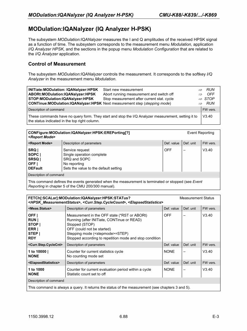
MODulation:IQANalyzer (IQ Analyzer H-PSK) CMU-K88/-K839/.../-K869
1150.3998.12 6.88 E-3
MODulation:IQANalyzer (IQ Analyzer H-PSK) The subsystem MODulation:IQANalyzer measures the I and Q amplitudes of the received HPSK signal as a function of time. The subsystem corresponds to the measurement menu Modulation, application I/Q Analyzer HPSK, and the sections in the popup menu Modulation Configuration that are related to the I/Q Analyzer application. Control of Measurement
The subsystem MODulation:IQANalyzer controls the measurement. It corresponds to the softkey I/Q Analyzer in the measurement menu Modulation.
INITiate:MODulation: IQANalyzer:HPSK Start new measurement ⇒ RUN ABORt:MODulation:IQANalyzer:HPSK Abort running measurement and switch off ⇒ OFF STOP:MODulation:IQANalyzer:HPSK Stop measurement after current stat. cycle ⇒ STOP CONTinue:MODulation:IQANalyzer:HPSK Next measurement step (stepping mode) ⇒ RUN Description of command FW vers.
These commands have no query form. They start and stop the I/Q Analyzer measurement, setting it to the status indicated in the top right column.
V3.40
CONFigure:MODulation:IQANalyzer:HPSK:EREPorting[?] Event Reporting <Report Mode><Report Mode> Description of parameters Def. value Def. unit FW vers.
SRQ | SOPC | SRSQ | OFF | DEFault
Service request Single operation complete SRQ and SOPC No reporting Sets the value to the default setting
OFF – V3.40
Description of command
This command defines the events generated when the measurement is terminated or stopped (see Event Reporting in chapter 5 of the CMU 200/300 manual).
FETCh[:SCALar]:MODulation:IQANalyzer:HPSK:STATus? Measurement Status <HPSK_MeasurementStatus>, <Curr.Step.CycleCount>, <ElapsedStatistics> <Meas.Status> Description of parameters Def. value Def. unit FW vers.
OFF | RUN | STOP | ERR | STEP | RDY
Measurement in the OFF state (*RST or ABORt) Running (after INITiate, CONTinue or READ) Stopped (STOP) OFF (could not be started) Stepping mode (<stepmode>=STEP) Stopped according to repetition mode and stop condition
OFF – V3.40
<Curr.Step.CycleCnt> Description of parameters Def. value Def. unit FW vers.
1 to 10000 | NONE
Counter for current statistics cycle No counting mode set
NONE – V3.40
<ElapsedStatistics> Description of parameters Def. value Def. unit FW vers.
1 to 1000 NONE
Counter for current evaluation period within a cycle Statistic count set to off
NONE – V3.40
Description of command
This command is always a query. It returns the status of the measurement (see chapters 3 and 5).

CMU-K88/-K839/.../-K869 MODulation:IQANalyzer (IQ Analyzer H-PSK)
1150.3998.12 6.89 E-3
Test Configuration
The commands of the following subsystems configure the I/Q Analyzer measurement in the Modulation menu. They correspond to the sections in the Modulation Configuration menu that are related to the I/Q Analyzer application. Subsystem CONTrol
The subsystem MODulation:IQANalyzer:CONTrol configures the measurement. It corresponds to the tab Control in the popup menu Modulation Configuration.
CONFigure:MODulation:IQANalyzer:HPSK:CONTrol:REPetition[?] Test Cycles <Repetition>, <Stop Cond>, <Step Mode><Repetition> Description of parameters Def. value Def. unit FW vers.
1 to 10000 | CONTinuous | SINGleshot | DEFault,
Multiple measurement (counting, until Status = STEP | RDY) Continuous measurement (until STOP or ABORT) Single shot measurement (until Status = RDY) Sets the value to the default setting
SING – V3.40
<Stop Cond> Description of parameters Def. value Def. unit FW vers.
NONE | SONerror | DEFault,
Continue measurement even in case of error Stop measurement in case of error (stop on error) Sets the value to the default setting
NONE – V3.40
<Step Mode> Description of parameters Def. value Def. unit FW vers.
STEP | NONE | DEFault
Interrupt measurement after each statistics cycle Continue measurement according to its rep. Mode Sets the value to the default setting
NONE – V3.40
Description of command
This command determines the repetition mode, stop condition, and stepping mode for the measurement.
Note:In the case of READ commands (READ:...), the <Repetition> parameter has no effect; the measurement is always stopped after a single shot.
CONFigure:MODulation:IQANalyzer:HPSK:CONTrol:RMODe[?] Result mode <Result Mode> <Result Mode> Description of parameters Def. value Def. unit FW-Vers.
SCALar | ARRay
Scalar values only Scalar measured values and arrays
ARR – V3.40
Description of command
This command specifies the type of measured values.
DEFault:MODulation:IQANalyzer:HPSK:CONTrol[?] Default Settings <Enable><Enable> Description of parameters Def. value Def. unit FW vers.
ON | OFF
The parameters are set to their default values Some or all parameters are not set to default
ON
– V3.40
Description of command
If used as a setting command with the parameter ON, this command sets all parameters of the subsystem MODulation:IQANalyzer:…:CONTrol to their default values (the setting OFF results in an error message).
If used as a query, the command returns whether all parameters are set to their default values (ON) or not (OFF).

MODulation:IQANalyzer (IQ Analyzer H-PSK) CMU-K88/-K839/.../-K869
1150.3998.12 6.90 E-3
CONFigure:MODulation:IQANalyzer:HPSK:DESPread[?] Despreading Mode <Despreading Mode><Despr. Mode> Description of parameters Def. value Def. unit FW vers.
OFF | DATA
Single demodulation/despreading of the signal per chip De-spreading only with symbols from the data channel
OFF
– V4.31
Description of command
If used as a setting command with the parameter OFF, this command sets the single demodulation/despreading of the signal per chip. With parameter DATA, only the signal symbols from the data channel are despread over the capture interval. The number of resulting I/Q values from the DATA de-spreading is different for each data channel modulation:
Modulation Type # of Results
B4 256 IQ values (I = 0)
Q4 256 IQ values
Q2 512 IQ values
Q4Q2 256 IQ values (W24) + 512 IQ values (W1
2)
E4E2 256 IQ values (W24) + 512 IQ values (W1
2)
The Q4Q2 and E4E2 constellation consists of two orthogonal walsh codes, hence the result is split into the W24
and W12 parts.
If used as a query, the command returns whether despreading is active per chip for all channels (OFF) or with data symbols (DATA).
Subsystem SUBarrays
The subsystem SUBarrays:MODulation:IQANalyzer defines the measurement range and the type of output values. CONFigure:SUBarrays:MODulation:IQANalyzer:HPSK[?] Definition of Subarrays <Mode>, <Start>, <Samples><Mode> Description of parameters Def. value Def. unit FW vers.
ALL Return all measurement values ALL – V3.40
<Start> Description of parameters Def. value Def. unit FW vers.
0 µs to 833 µs
Start time in current range NAN s V3.40
<Samples> Description of parameters Def. value Def. unit FW vers.
0 to 4096 Number of samples in current range NAN – V3.40
Description of command
This command configures the READ:SUBarrays..., FETCh:SUBarrays..., and SAMPle:SUBarrays:MODulation:IQANalyzer commands. It restricts the measurement to up to 32 subranges where either all measurement results (the number of which is given by the second numerical parameter) or a single statistical value is returned. The subranges are defined by the start time and the number of test points which are located on a fixed, equidistant grid with a step width of 1 symbol period.
The subranges may overlap but must be within the total range of the I/Q Analyzer measurement. Test points outside this range are not measured (result NAN).
By default, only one range corresponding to the total measurement range is used and all measurement values are returned.

CMU-K88/-K839/.../-K869 MODulation:IQANalyzer (IQ Analyzer H-PSK)
1150.3998.12 6.91 E-3
Measured Values
The subsystem MODulation:IQANalyzer measures and returns the I/Q Analyzer results. No limit check is perfomed. The subsystem corresponds to the various output elements in the measurement menu MODulation, application I/Q Analyzer.
Scalar Results READ[:SCALar]:MODulation:IQANalyzer:HPSK? Start single shot measurement and return results FETCh[:SCALar]:MODulation: IQANalyzer:HPSK? Read out meas. results (unsynchronized) SAMPle[:SCALar]:MODulation: IQANalyzer:HPSK? Read out measurement results (synchronized) Returned values Value range Def. value Def. unit FW vers.
IQ Peak (x3), IQ RMS (x3), Carrier Feedthrough (x3), I/Q Imbalance (x3), Carrier Freq. Error (x3), Transmit Time Error (x3), Waveform Quality (Rho) (x3),AT Power (x3),
0.0 % to 100.0 % 0.0 % to 100.0 % –120.0 dB to –20.0 dB –120.0 dB to –20.0 dB 0 Hz to 1000 Hz 0 µs to 10 µs0 to 1 –133.0 dBm to +19.0 dBm
NAN NAN
NAN NAN NAN NAN NAN NAN
%%
dB dB Hz µs–dB
V3.40
Description of command
These commands are always queries. They start a modulation measurement and output the scalar measurement results (see chapter 4). The calculation of results in an average or peak measurement is described in chapter 3 (see calculation of statistical quantities). The symbol (x3) behind a value indicates that the list contains three results corresponding to the Current, the Average, and the MaxMin value.
Normalized I phase amplitude READ:ARRay:MODulation:IQANalyzer:HPSK:IPHase? Start single shot measurement and return results FETCh:ARRay:MODulation:IQANalyzer:HPSK:IPHase? Read measurement results (unsynchronized) SAMPle:ARRay:MODulation:IQANalyzer:HPSK:IPHase? Read measurement results (synchronized) Returned values Value range Def. value Def. unit FW vers.
–2.0 to +2.0, ..., –2.0 to +2.0
1st value for normalized I amplitude, 4096th value for normalized I amplitude
NAN NAN
–
–
V3.40
Description of command
These commands are always queries. They return the normalized I amplitude. The number of measured values is 4096. This corresponds to an oversampling factor of four compared to the OEMP modulation measurements. The time range of 0 symbols to 833 microseconds.
Normalized Q phase amplitude READ:ARRay:MODulation:IQANalyzer:HPSK:QPHase? Start single shot measurement and return results FETCh:ARRay:MODulation:IQANalyzer:HPSK:QPHase? Read measurement results (unsynchronized) SAMPle:ARRay:MODulation:IQANalyzer:HPSK:QPHase? Read measurement results (synchronized) Returned values Value range Def. value Def. unit FW vers.
–2.0 to +2.0, ..., –2.0 to +2.0
1st value for normalized Q amplitude, 4096th value for normalized Q amplitude
NAN NAN
–
–
V3.40
Description of command
These commands are always queries. They return the normalized Q amplitude. The number of measured values is 4096. This corresponds to an oversampling factor of four compared to the OEMP modulation measurements. The time range of 0 symbols to 833 microseconds.

SPECtrum:ACP (ACP Spectrum) CMU-K88/-K839/.../-K869
1150.3998.12 6.92 E-3
SPECtrum:ACP (ACP Spectrum) The subsystem SPECtrum:ACP measures the power of four adjacent channel pairs. These four pairs correspond to symmetrical frequency offsets to the RF frequency (command [SENSe]:RFANalyzer:FREQuency[?]). The subsystem corresponds to the measurement menu Spectrum and the associated popup menu Spectrum Configuration. Control of Measurement
The subsystem SPECtrum:ACP controls the adjacent channel power spectrum measurement. It corresponds to the softkey ACP in the measurement menu Spectrum.
INITiate:SPECtrum:ACP Start new measurement ⇒ RUN ABORt:SPECtrum:ACP Abort running measurement and switch off ⇒ OFF STOP:SPECtrum:ACP Stop measurement after current stat. cycle ⇒ STOP CONTinue:SPECtrum:ACP Next measurement step (stepping mode) ⇒ RUN Description of command FW vers.
These commands have no query form. They start and stop the ACP spectrum measurement, setting it to the status indicated in the top right column.
V3.40
CONFigure:SPECtrum:ACP:EREPorting[?] Event Reporting <Report Mode><Report Mode> Description of parameters Def. value Def. unit FW vers.
SRQ | SOPC | SRSQ | DEFault | OFF
Service request Single operation complete SRQ and SOPC Sets the value to the default setting No reporting
OFF – V3.40
Description of command
This command defines the events generated when the measurement is terminated or stopped (see Event Reporting in chapter 5 of the CMU 200/300 manual).
FETCh[:SCALar]:SPECtrum:ACP:STATus? Measurement Status <MeasurementStatus>, <Curr.Step.CycleCount>, <ElapsedStatistics> <Meas.Status> Description of parameters Def. value Def. unit FW vers.
OFF | RUN | STOP | ERR | STEP | RDY,
Measurement in the OFF state (*RST or ABORt) Running (after INITiate, CONTinue or READ) Stopped (STOP) OFF (could not be started) Stepping mode (<stepmode>=STEP) Stopped according to repetition mode and stop condition
OFF – V3.40
<Curr.Step.CycleCnt> Description of parameters Def. value Def. unit FW vers.
1 to 10000 | NONE,
Counter for current statistics cycle No counting mode set
NONE – V3.40
<ElapsedStatistics> Description of parameters Def. value Def. unit FW vers.
1 to 1000 NONE
Counter for current evaluation period within a cycle Statistic count set to off
NONE – V3.40
Description of command
This command is always a query. It returns the status of the measurement (see chapters 3 and 5).

CMU-K88/-K839/.../-K869 SPECtrum:ACP (ACP Spectrum)
1150.3998.12 6.93 E-3
Test Configuration
The commands of the following subsystems configure the ACP Spectrum measurement in the Spectrum menu. They correspond to the Spectrum Configuration popup menu. Subsystem CONTrol
The subsystem SPECtrum:ACP:CONTrol configures the ACP Spectrum measurement. It defines the repetition mode, statistic count, stop condition and the offset frequencies of the measurement. It corresponds to the tab Control in the popup menu Spectrum Configuration.
CONFigure:SPECtrum:ACP:CONTrol[?] Scope of Measurement <StatisticCount>, <Repetition>, <Stop Cond>, <Step Mode> <StatisticCount> Description of parameters Def. value Def. unit FW vers.
1 to 1000, Number of bursts per statistics cycle 100 – V3.40
<Repetition> Description of parameters Def. value Def. unit FW vers.
1 to 10000 | CONTinuous | SINGleshot | DEFault,
Multiple measurement (counting, until Status = STEP | RDY) Continuous measurement (until STOP or ABORT) Single shot measurement (until Status = RDY)Sets the value to the default setting
SING – V3.40
<Stop Cond> Description of parameters Def. value Def. unit FW vers.
NONE | SONerror | DEFault,
Continue measurement even in case of error Stop measurement in case of error (stop on e READ[:SCALar]:SPECtrum:ACP?rror) Sets the value to the default setting
NONE – V3.40
<Step Mode> Description of parameters Def. value Def. unit FW vers.
STEP | NONE | DEFault
Interrupt measurement after each statistics cycle Continue measurement according to its rep. Mode Sets the value to the default setting
NONE – V3.40
Description of command
This command combines the ...CONTrol:RMODe,...CONTrol:STATistics and the ...CONTrol:REPetition commands, see below.
CONFigure:SPECtrum:ACP:CONTrol:STATistics[?] Statistic Count <Statistics Count > <Statistics Count> Description of parameters Def. value Def. unit FW-Vers.
1 to 1000 Number of bursts per statistics cycle 100 – V3.40
Description of command
This command defines the number of bursts forming a statistics cycle.

SPECtrum:ACP (ACP Spectrum) CMU-K88/-K839/.../-K869
1150.3998.12 6.94 E-3
CONFigure:SPECtrum:ACP:CONTrol:REPetition[?] Test Cycles <Repetition>, <Stop Cond>, <Step Mode> <Repetition> Description of parameters Def. value Def. unit FW vers.
1 to 10000 | CONTinuous | SINGleshot | DEFault,
Multiple measurement (counting, until Status = STEP | RDY) Continuous measurement (until STOP or ABORT) Single shot measurement (until Status = RDY)Sets the value to the default setting
SING – V3.40
<Stop Cond> Description of parameters Def. value Def. unit FW vers.
NONE | SONerror | DEFault,
Continue measurement even in case of error Stop measurement in case of error (stop on error) Sets the value to the default setting
NONE – V3.40
<Step Mode> Description of parameters Def. value Def. unit FW vers.
STEP | NONE | DEFault
Interrupt measurement after each statistics cycle Continue measurement according to its rep. Mode Sets the value to the default setting
NONE – V3.40
Description of command
This command determines the repetition mode, stop condition, and stepping mode for the measurement.
Note: In the case of READ commands (READ:...), the <Repetition> parameter has no effect; the measurement is always stopped after a single shot.
DEFault:SPECtrum:ACP:CONTrol[?] Default Settings <Enable> <Enable> Description of parameters Def. value Def. unit FW vers.
ON | OFF
The parameters are set to their default values Some or all parameters are not set to default
ON
– V3.40
Description of command
If used as a setting command with the parameter ON, this command sets all parameters of the subsystem SPECtrum:ACP:CONTrol to their default values (the setting OFF results in an error message).
If used as a query the command returns whether all parameters are set to their default values (ON) or not (OFF).

CMU-K88/-K839/.../-K869 SPECtrum:ACP (ACP Spectrum)
1150.3998.12 6.95 E-3
CONFigure:SPECtrum:ACP:CONTrol:FOFFset:ACP<nr>[?] ACP Frequency Offset <Freq. Offset>
<Freq. Offset> Description of parameters Def. value Def. unit FW vers.
0 to 2 MHz | OFF | ON 0 to 2 MHz | OFF | ON
0 to 2 MHz | OFF | ON 0 to 2 MHz | OFF | ON 0 to 2 MHz | OFF | ON 0 to 2 MHz | OFF | ON 0 to 2 MHz | OFF | ON 0 to 2 MHz | OFF | ON 0 to 2 MHz | OFF | ON 0 to 2 MHz | OFF | ON 0 to 2 MHz | OFF | ON 0 to 2 MHz | OFF | ON
The ACP frequency offset depends on the network standard: Band Class 0, US Cellular Measurement disabled, result INV Enable measurement, last setting re-activated
Band Class 0, Korean Cellular Measurement disabled, result INV Enable measurement, last setting re-activated
Band Class 1, North American PCS Measurement disabled, result INV Enable measurement, last setting re-activated
Band Class 2, TACS Measurement disabled, result INV Enable measurement, last setting re-activated
Band Class 3, JTACS Measurement disabled, result INV Enable measurement, last setting re-activated
Band Class 4, Korean PCS Measurement disabled, result INV Enable measurement, last setting re-activated
Band Class 5, NMT 450 Measurement disabled, result INV Enable measurement, last setting re-activated
Band Class 6, IMT-2000 Measurement disabled, result INV Enable measurement, last setting re-activated
Band Class 7, North American 700 MHz Measurement disabled, result INV Enable measurement, last setting re-activated
Band Class 8, 1800 MHz Measurement disabled, result INV Enable measurement, last setting re-activated
Band Class 9, North American 900 MHz Measurement disabled, result INV Enable measurement, last setting re-activated
Band Class 10, Secondary 800 MHz Measurement disabled, result INV Enable measurement, last setting re-activated
<nr> = 1: 870.00 kHz <nr> = 2: 885.00 kHz <nr> = 3: 900.00 kHz <nr> = 4: 1980.00 kHz <nr> = 1: 870.00 kHz <nr> = 2: 885.00 kHz <nr> = 3: 900.00 kHz <nr> = 4: 1980.00 kHz
<nr> = 1: 1150.00 kHz <nr> = 2: 1200.00 kHz <nr> = 3: 1250.00 kHz <nr> = 4: 1980.00 kHz <nr> = 1: 870.00 kHz <nr> = 2: 885.00 kHz <nr> = 3: 900.00 kHz <nr> = 4: 1980.00 kHz <nr> = 1: 870.00 kHz <nr> = 2: 885.00 kHz <nr> = 3: 900.00 kHz <nr> = 4: 1980.00 kHz <nr> = 1: 1150.00 kHz <nr> = 2: 1200.00 kHz <nr> = 3: 1250.00 kHz <nr> = 4: 1980.00 kHz <nr> = 1: 870.00 kHz <nr> = 2: 885.00 kHz <nr> = 3: 900.00 kHz <nr> = 4: 1980.00 kHz <nr> = 1: 1150.00 kHz <nr> = 2: 1200.00 kHz <nr> = 3: 1250.00 kHz <nr> = 4: 1980.00 kHz <nr> = 1: 870.00 kHz <nr> = 2: 885.00 kHz <nr> = 3: 900.00 kHz <nr> = 4: 1980.00 kHz <nr> = 1: 1150.00 kHz <nr> = 2: 1200.00 kHz <nr> = 3: 1250.00 kHz <nr> = 4: 1980.00 kHz <nr> = 1: 870.00 kHz <nr> = 2: 885.00 kHz <nr> = 3: 900.00 kHz <nr> = 4: 1980.00 kHz <nr> = 1: 870.00 kHz <nr> = 2: 885.00 kHz <nr> = 3: 900.00 kHz <nr> = 4: 1980.00 kHz
Hz V3.40
V3.40

SPECtrum:ACP (ACP Spectrum) CMU-K88/-K839/.../-K869
1150.3998.12 6.96 E-3
0 to 2 MHz | OFF | ON 0 to 2 MHz | OFF | ON 0 to 2 MHz | OFF | ON 0 to 2 MHz | OFF | ON 0 to 2 MHz | OFF | ON 0 to 2 MHz | OFF | ON 0 to 2 MHz | OFF | ON
Band Class 11, European 400 MHz PAMRMeasurement disabled, result INV Enable measurement, last setting re-activated
Band Class 12, 800 MHz PAMR Measurement disabled, result INV Enable measurement, last setting re-activated
Band Class 13, IMT-2000 2.5 GHz Ext. Measurement disabled, result INV Enable measurement, last setting re-activated
Band Class 14, US PCS 1900 MHz Measurement disabled, result INV Enable measurement, last setting re-activated
Band Class 15, AWS Band Measurement disabled, result INV Enable measurement, last setting re-activated
Band Class 16, US 2.5 GHz Band Measurement disabled, result INV Enable measurement, last setting re-activated
Band Class 17, US 2.5 GHz Forward Link Only Band Measurement disabled, result INV Enable measurement, last setting re-activated
<nr> = 1: 870.00 kHz <nr> = 2: 885.00 kHz <nr> = 3: 900.00 kHz <nr> = 4: 1980.00 kHz <nr> = 1: 870.00 kHz <nr> = 2: 885.00 kHz <nr> = 3: 900.00 kHz <nr> = 4: 1980.00 kHz <nr> = 1: 1150.00 kHz <nr> = 2: 1200.00 kHz <nr> = 3: 1250.00 kHz <nr> = 4: 1980.00 kHz <nr> = 1: 1150.00 kHz <nr> = 2: 1200.00 kHz <nr> = 3: 1250.00 kHz <nr> = 4: 1980.00 kHz <nr> = 1: 1150.00 kHz <nr> = 2: 1200.00 kHz <nr> = 3: 1250.00 kHz <nr> = 4: 1980.00 kHz <nr> = 1: 1150.00 kHz <nr> = 2: 1200.00 kHz <nr> = 3: 1250.00 kHz <nr> = 4: 1980.00 kHz <nr> = 1: 1150.00 kHz <nr> = 2: 1200.00 kHz <nr> = 3: 1250.00 kHz <nr> = 4: 1980.00 kHz
V4.20
V4.20
V4.20
V4.20
V4.20
V4.20
V4.20
Description of command
This command determines four frequency offset values (<nr> = 1 to 4) which define the four adjacent channel pairs. OFF will disable the mesurement on the specified frequency pair and INV will be returned as result. See also the command CONFigure:NETWork:STANdard. For all of the above frequency offsets, the following parameters may also be used:
MINimum Sets the frequency offset value to the respective minimum value MAXimum Sets the frequency offset value to the respective maximum value DEFault Sets the frequency offset value to the respective default value
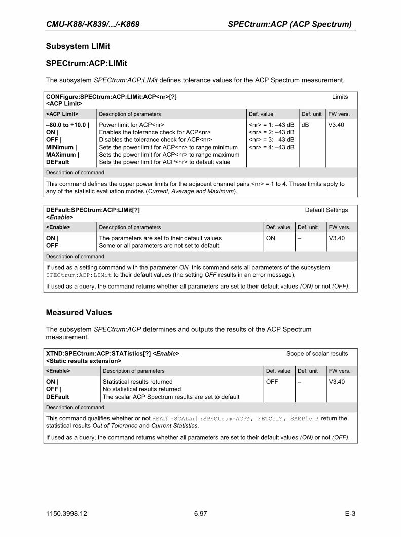
CMU-K88/-K839/.../-K869 SPECtrum:ACP (ACP Spectrum)
1150.3998.12 6.97 E-3
Subsystem LIMit
SPECtrum:ACP:LIMit
The subsystem SPECtrum:ACP:LIMit defines tolerance values for the ACP Spectrum measurement. CONFigure:SPECtrum:ACP:LIMit:ACP<nr>[?] Limits <ACP Limit> <ACP Limit> Description of parameters Def. value Def. unit FW vers.
–80.0 to +10.0 | ON | OFF | MINimum | MAXimum | DEFault
Power limit for ACP<nr> Enables the tolerance check for ACP<nr> Disables the tolerance check for ACP<nr> Sets the power limit for ACP<nr> to range minimum Sets the power limit for ACP<nr> to range maximum Sets the power limit for ACP<nr> to default value
<nr> = 1: –43 dB<nr> = 2: –43 dB<nr> = 3: –43 dB<nr> = 4: –43 dB
dB
V3.40
Description of command
This command defines the upper power limits for the adjacent channel pairs <nr> = 1 to 4. These limits apply to any of the statistic evaluation modes (Current, Average and Maximum).
DEFault:SPECtrum:ACP:LIMit[?] Default Settings <Enable><Enable> Description of parameters Def. value Def. unit FW vers.
ON | OFF
The parameters are set to their default values Some or all parameters are not set to default
ON
– V3.40
Description of command
If used as a setting command with the parameter ON, this command sets all parameters of the subsystem SPECtrum:ACP:LIMit to their default values (the setting OFF results in an error message).
If used as a query, the command returns whether all parameters are set to their default values (ON) or not (OFF).
Measured Values
The subsystem SPECtrum:ACP determines and outputs the results of the ACP Spectrum measurement. XTND:SPECtrum:ACP:STATistics[?] <Enable> Scope of scalar results <Static results extension> <Enable> Description of parameters Def. value Def. unit FW vers.
ON | OFF | DEFault
Statistical results returned No statistical results returned The scalar ACP Spectrum results are set to default
OFF
– V3.40
Description of command
This command qualifies whether or not READ[:SCALar]:SPECtrum:ACP?, FETCh…?, SAMPle…? return the statistical results Out of Tolerance and Current Statistics.
If used as a query, the command returns whether all parameters are set to their default values (ON) or not (OFF).

SPECtrum:ACP (ACP Spectrum) CMU-K88/-K839/.../-K869
1150.3998.12 6.98 E-3
Scalar results:
READ[:SCALar]:SPECtrum:ACP? Start single shot measurement and return results FETCh[:SCALar]:SPECtrum:ACP? Read out measurement results (unsynchronized) SAMPle[:SCALar]:SPECtrum:ACP? Read out measurement results (synchronized) Returned values Value range Def. value Def. unit FW vers.
Power of adj. Channel –4 (Current), Power of adj. Channel –3 (Current), Power of adj. Channel –2 (Current), Power of adj. Channel –1 (Current), Power of adj. Channel +1 (Current), Power of adj. Channel +2 (Current), Power of adj. Channel +3 (Current), Power of adj. Channel +4 (Current), Power of adj. Channel –4 (Average), Power of adj. Channel –3 (Average), Power of adj. Channel –2 (Average), Power of adj. Channel –1 (Average), Power of adj. Channel +1 (Average), Power of adj. Channel +2 (Average), Power of adj. Channel +3 (Average), Power of adj. Channel +4 (Average), Power of adj. Channel –4 (Maximum), Power of adj. Channel –3 (Maximum), Power of adj. Channel –2 (Maximum), Power of adj. Channel –1 (Maximum), Power of adj. Channel +1 (Maximum), Power of adj. Channel +2 (Maximum), Power of adj. Channel +3 (Maximum), Power of adj. Channel +4 (Maximum), Channel Power (Current), Channel Power (Average), Channel Power (Maximum), Out of Tolerance, Current Statistics
–80.0 dB to 0.0 dB
–80.0 dB to 0.0 dB
–80.0 dB to 0.0 dB
–80.0 dBm to 0.0 dBm
0 to 100 % 1 to 10000
NAN NAN NAN NAN NAN NAN NAN NAN NAN NAN NAN NAN NAN NAN NAN NAN NAN NAN NAN NAN NAN NAN NAN NAN NAN NAN NAN NAN NAN
dB
dB
dB
dBm
––
V3.40
Description of command
These commands are always queries. They start a measurement and output all scalar measurement results.
Note: <OutOfTolerance> and <CurrentStatistics> are returned only if XTND:SPECtrum:ACP:STATistics[?] is set to ON.

CMU-K88/-K839/.../-K869 SPECtrum:ACP (ACP Spectrum)
1150.3998.12 6.99 E-3
CALCulate[:SCALar]:SPECtrum:ACP:MATChing:LIMit? <Limit> Matching Returned values Value range Def. value Def. unit FW vers.
Tolerance Channel –4 (Current), Tolerance Channel –3 (Current), Tolerance Channel –2 (Current), Tolerance Channel –1 (Current), Tolerance Channel +1 (Current), Tolerance Channel +2 (Current), Tolerance Channel +3 (Current), Tolerance Channel +4 (Current), Tolerance Channel –4 (Average), Tolerance Channel –3 (Average), Tolerance Channel –2 (Average), Tolerance Channel –1 (Average), Tolerance Channel +1 (Average), Tolerance Channel +2 (Average), Tolerance Channel +3 (Average), Tolerance Channel +4 (Average), Tolerance Channel –4 (Maximum), Tolerance Channel –3 (Maximum), Tolerance Channel –2 (Maximum), Tolerance Channel –1 (Maximum), Tolerance Channel +1 (Maximum), Tolerance Channel +2 (Maximum), Tolerance Channel +3 (Maximum), Tolerance Channel +4 (Maximum),
NMAU | NMAL | INV | OK
NMAU | NMAL | INV | OK
NMAU | NMAL | INV | OK
INV
INV
INV
–
–
–
V3.40
Description of command
This command is always a query. It indicates whether and in which way the (fixed) limit has been exceeded. The following messages may be generated:
NMAU Tolerance value underflow not matching, underflow NMAL Tolerance value exceeded not matching, overflow INV Measurement invalid invalid
OK Tolerance value matched

CDPower:CDPW (Code Domain Power) CMU-K88/-K839/.../-K869
1150.3998.12 6.100 E-3
CDPower:CDPW (Code Domain Power) The subsystem CDPower:CDPW measures the Code Domain Power output of the access terminal. Both the RRI and the Pilot time slot are evaluated in the same measurement shot. The CDPower:CDPW subsystem corresponds to the measurement menu Code Domain Power, application CDP and the sections related to this application in the associated popup menu Code Domain Power Configuration. Control of Measurement
The subsystem CDPower:CDPW controls the code domain power measurement. It corresponds to the softkey CDP in the measurement menu Code Domain Power.
INITiate:CDPower:CDPW Start new measurement ⇒ RUN ABORt:CDPower:CDPW Abort running measurement and switch off ⇒ OFF STOP:CDPower:CDPW Stop measurement after current stat. cycle ⇒ STOP CONTinue:CDPower:CDPW Next measurement step (stepping mode) ⇒ RUN Description of command FW vers.
These commands have no query form. They start and stop the code domain power measurement, setting it to the status indicated in the top right column.
V3.40
CONFigure:CDPower:CDPW:EREPorting[?] Event Reporting <EventReporting><EventReporting> Description of parameters Def. value Def. unit FW vers.
SRQ | SOPC | SRSQ | DEFault | OFF
Service request Single operation complete SRQ and SOPC Sets the value to the default setting No reporting
OFF – V3.40
Description of command
This command defines the events generated when the measurement is terminated or stopped (see Event Reporting in chapter 5 of the CMU 200/300 manual).
FETCh[:SCALar]:CDPower:CDPW:STATus? Measurement Status <MeasurementStatus>, <Curr.Step.CycleCount>, <ElapsedStatistics> <Meas.Status> Description of parameters Def. value Def. unit FW vers.
OFF | RUN | STOP | ERR | STEP | RDY,
Measurement in the OFF state (*RST or ABORt) Running (after INITiate, CONTinue or READ) Stopped (STOP) OFF (could not be started) Stepping mode (<stepmode>=STEP) Stopped according to repetition mode and stop condition
OFF – V3.40
<Cycle Count> Description of parameters Def. value Def. unit FW vers.
1 to 10000 | NONE,
Counter for current statistics cycle No counting mode set
NONE – V3.40
<ElapsedStatistics> Description of parameters Def. value Def. unit FW vers.
1 to 1000 NONE
Counter for current evaluation period within a cycle Statistic count set to off
NONE – V3.40
Description of command
This command is always a query. It returns the status of the measurement (see chapters 3 and 5).

CMU-K88/-K839/.../-K869 CDPower:CDPW (Code Domain Power)
1150.3998.12 6.101 E-3
Test Configuration
The commands of the following subsystems configure the Code Domain Power measurement in the Code Domain Power menu. They correspond to the Code Domain Power Configuration popup menu.
Subsystem CONTrol
The subsystem CDPower:CDPW:CONTrol configures the Code Domain Power measurement. It defines the result mode, result order, repetition mode, statistic count and stop condition of the measurement. It corresponds to the tab Control in the popup menu Code Domain Power Configuration.
CONFigure:CDPower:CDPW:CONTrol[?] Scope of Measurement <Result Mode>, <Current Statistics>, <Repetition>, <Stop Cond>, <Step Mode> <Result Mode> Description of parameters Def. value Def. unit FW vers.
SCALar | ARRay,
Scalar values only (incl. ramp matching) Scalar measured values and arrays
ARR – V3.40
<Current Statistics> Description of parameters Def. value Def. unit FW vers.
1 to 1000, Number of bursts per statistics cycle 100 – V3.40
<Repetition> Description of parameters Def. value Def. unit FW vers.
1 to 10000 | CONTinuous | SINGleshot | DEFault,
Multiple measurement (counting, until Status = STEP | RDY) Continuous measurement (until STOP or ABORT) Single shot measurement (until Status = RDY)Sets the value to the default setting
SING – V3.40
<Stop Cond> Description of parameters Def. value Def. unit FW vers.
NONE | SONerror | DEFault,
Continue measurement even in case of error Stop measurement in case of error (stop on error) Sets the value to the default setting
NONE – V3.40
<Step Mode> Description of parameters Def. value Def. unit FW vers.
STEP | NONE | DEFault
Interrupt measurement after each statistics cycle Continue measurement according to its rep. Mode Sets the value to the default setting
NONE – V3.40
Description of command
This command combines the ...CONTrol:RMODe,...CONTrol:STATistics and the ...CONTrol:REPetition commands, see below.
CONFigure:CDPower:CDPW:CONTrol:RMODe[?] Result mode <Result Mode> <Result Mode> Description of parameters Def. value Def. unit FW-Vers.
SCALar | ARRay
Scalar values only (incl. ramp matching) Scalar measured values and arrays
ARR – V3.40
Description of command
This command specifies the type of measured values.

CDPower:CDPW (Code Domain Power) CMU-K88/-K839/.../-K869
1150.3998.12 6.102 E-3
CONFigure:CDPower:CDPW:CONTrol:STATistics[?] Statistic Count <Current Statistics><Current Statistics > Description of parameters Def. value Def. unit FW-Vers.
1 to 1000 Number of bursts per statistics cycle 100 – V3.40
Description of command
This command defines the number of bursts forming a statistics cycle.
CONFigure:CDPower:CDPW:CONTrol:REPetition[?] Test Cycles <Repetition>, <Stop Cond>, <Step Mode> <Repetition> Description of parameters Def. value Def. unit FW vers.
1 to 10000 | CONTinuous | SINGleshot | DEFault,
Multiple measurement (counting, until Status = STEP | RDY) Continuous measurement (until STOP or ABORT) Single shot measurement (until Status = RDY)Sets the value to the default setting
SING – V3.40
<Stop Cond> Description of parameters Def. value Def. unit FW vers.
NONE | SONerror | DEFault,
Continue measurement even in case of error Stop measurement in case of error (stop on error) Sets the value to the default setting
NONE – V3.40
<Step Mode> Description of parameters Def. value Def. unit FW vers.
STEP | NONE | DEFault
Interrupt measurement after each statistics cycle Continue measurement according to its rep. Mode Sets the value to the default setting
NONE – V3.40
Description of command
This command determines the repetition mode, stop condition, and stepping mode for the measurement.
Note: In the case of READ commands (READ:...), the <Repetition> parameter has no effect; the measurement is always stopped after a single shot.
CONFigure:CDPower:CDPW:CONTrol:RORDer[?] Result Order <Result Order> <Result Order> Description of parameters Def. value Def. unit FW vers.
HADamard | BITReverse
Walsh code channels returned using Hadamard matrix Walsh code channels returned at MSB to LSB
HAD – V3.40
Description of command
This command defines the method used to display the code channels. HADamard displays the code channels in order determined by the Hadamard matrix. BITReverse displays the code channels so that the related code channels are adjacent to each other.
This setting is only available for Code Domain and Peak Code Domain Error measurement applications.
DEFault:CDPower:CDPW:CONTrol[?] <Enable> Default Settings <Enable> Description of parameters Def. value Def. unit FW vers.
ON | OFF
The parameters are set to their default values Some or all parameters are not set to default
ON
– V3.40
Description of command
If used as a setting command with the parameter ON, this command sets all parameters of the subsystem CDPower:CDPW:CONTrol to their default values (the setting OFF results in an error message).
If used as a query the command returns whether all parameters are set to their default values (ON) or not (OFF).

CMU-K88/-K839/.../-K869 CDPower:CDPW (Code Domain Power)
1150.3998.12 6.103 E-3
Subsystem LIMit
CDPower:CPCCommon:LIMit
The subsystem CDPower:CPCCommon:LIMit defines common tolerance values for the scalar results of the following Code Domain Power applications (CPCCommon): • Code Domain Power (CDP)• Peak Code Domain Error Power (PCDep)• Channel Power (CHPW)
CONFigure:CDPower:CPCCommon:CMAX:LIMit:ASYMmetric[:COMBined][?] Limits <Carrier Feedthrough Limit>, <Carrier Freq. Error Limit>, <Rho Limit> <Carrier Feedthrough Limit> Description of parameters Def. value Def. unit FW vers.
–120.0 to –20.0 | DEFault | MINimum | MAXimum | OFF,
Carrier feedthrough limit Sets the value to the default setting Sets the value to the minimum range value Sets the value to the maximum range value Disables the tolerance check
–40.0 dB
V3.40
<Carrier Freq. Error Limit> Description of parameters Def. value Def. unit FW vers.
0 to 1000.0 Hz | DEFault | MINimum | MAXimum | OFF,
Carrier frequency error limit Sets the value to the default setting Sets the value to the minimum range value Sets the value to the maximum range value Disables the tolerance check
300.0 Hz V3.40
<Rho Limit> Description of parameters Def. value Def. unit FW vers.
0.0 to 1.0 | DEFault | MINimum | MAXimum | OFF
Correlated power to the total power ratio limit Sets the value to the default setting Sets the value to the minimum range value Sets the value to the maximum range value Disables the tolerance check
0.944 – V3.40
Description of command
This command defines upper limits for the different traces and for the scalar modulation parameters derived from them. The keywords CMAX and AVERage refer to the Current and Max. display and for the Average display, respectively.

CDPower:CDPW (Code Domain Power) CMU-K88/-K839/.../-K869
1150.3998.12 6.104 E-3
CONFigure:CDPower:CPCCommon:AVERage:LIMit:ASYMmetric[:COMBined][?] Limits <Carrier Feedthrough Limit Average>, <Carrier Freq. Error Limit Average>, <Rho Limit Average> <Carrier Feedthrough Limit> Description of parameters Def. value Def. unit FW vers.
–120.0 to –20.0 | DEFault | MINimum | MAXimum | OFF,
Carrier feedthrough limit Sets the value to the default setting Sets the value to the minimum range value Sets the value to the maximum range value Disables the tolerance check
–40.0 dB
V3.40
<Carrier Freq. Error Limit> Description of parameters Def. value Def. unit FW vers.
0 to 1000.0 Hz | DEFault | MINimum | MAXimum | OFF,
Carrier frequency error limit Sets the value to the default setting Sets the value to the minimum range value Sets the value to the maximum range value Disables the tolerance check
300.0 Hz V3.40
<Rho Limit> Description of parameters Def. value Def. unit FW vers.
0.0 to 1.0 | DEFault | MINimum | MAXimum | OFF
Correlated power to the total power ratio limit Sets the value to the default setting Sets the value to the minimum range value Sets the value to the maximum range value Disables the tolerance check
0.944 – V3.40
Description of command
This command defines upper limits for the different traces and for the scalar modulation parameters derived from them. The keywords CMAX and AVERage refer to the Current and Max. display and for the Average display, respectively.
DEFault:CDPower:CPCCommon:LIMit[?] Default Settings <Enable><Enable> Description of parameters Def. value Def. unit FW vers.
ON | OFF
The common CDP parameters are set to their default values Some or all parameters are not set to default
ON
– V3.40
Description of command
If used as a setting command with the parameter ON, this command sets all parameters of the subsystem CDPower:CPCCommon:LIMit to their default values (the setting OFF results in an error message).
If used as a query, the command returns whether all parameters are set to their default values (ON) or not (OFF).

CMU-K88/-K839/.../-K869 CDPower:CDPW (Code Domain Power)
1150.3998.12 6.105 E-3
CDPower:CDPW:LIMit
The subsystem CDPower:CDPW:LIMIT defines the tolerance values that apply to the Code Domain Power application only. CONFigure:CDPower:CDPW:CMAX:LIMit:ASYMmetric[:COMBined][?] Limits <CDP Limit Y> <CDP Limit Y> Description of parameters Def. value Def. unit FW vers.
–60.0 to 0 | DEFault | MINimum | MAXimum | OFF
Peak code domain power Y limit Sets the value to the default setting Sets the value to the minimum range value Sets the value to the maximum range value Disables the tolerance check
–23.0 dB
V3.40
Description of command
This command defines the upper limit for the code domain power of the inactive channels (I and Q signal). The active channels are not checked. The keywords CMAX and AVERage refer to the Current and Max. display and for the Average display, respectively.
CONFigure:CDPower:CDPW:AVERage:LIMit:ASYMmetric[:COMBined][?] Limits <CDP Limit Y Average> <CDP Limit Y Average> Description of parameters Def. value Def. unit FW vers.
–60.0 to 0 | DEFault | MINimum | MAXimum | OFF
Peak code domain power Y limit Sets the value to the default setting Sets the value to the minimum range value Sets the value to the maximum range value Disables the tolerance check
–23.0 dB
V3.40
Description of command
This command defines the upper limit for the code domain power of the inactive channels (I and Q signal). The active channels are not checked. The keywords CMAX and AVERage refer to the Current and Max. display and for the Average display, respectively.
CONFigure:CDPower:CDPW:LIMit:IQLCheck[?] I/Q Leakage Check <IQ Leakage Check> <IQ Leakage Check> Description of parameters Def. value Def. unit FW vers.
DEFault | OFF | ON
Sets the value to the default setting I/Q Leakage Check disabled I/Q Leakage Check enabled
ON –
V3.40
Description of command
This command enables or disables the I/Q leakage check. When enabled, the tolerance check will be performed for all inactive channels regardless of wether the corresponding channel on the opposite signal phase is active or not. Disabling the I/Q leakage check will only indicate tolerance violations of those inactive channels that have no active correspondance on the opposite signal phase.

CDPower:CDPW (Code Domain Power) CMU-K88/-K839/.../-K869
1150.3998.12 6.106 E-3
DEFault:CDPower:CDPW:LIMit[?] Default Settings <Enable><Enable> Description of parameters Def. value Def. unit FW vers.
ON | OFF
The parameters are set to their default values Some or all parameters are not set to default
ON
– V3.40
Description of command
If used as a setting command with the parameter ON, this command sets all parameters of the subsystem CDPower:CDPW:LIMit to their default values (the setting OFF results in an error message).
If used as a query, the command returns whether all parameters are set to their default values (ON) or not (OFF).
Measured Values
The subsystem CDPower:CDPW determines and outputs the results of the Code Domain Power measurement.
Scalar results: READ[:SCALar]:CDPower:CDPW? Start single shot measurement and return results FETCh[:SCALar]:CDPower:CDPW? Read out measurement results (unsynchronized) SAMPle[:SCALar]:CDPower:CDPW? Read out measurement results (synchronized) Returned values Value range Def. value Def. unit FW vers.
AT Power (x3), Carrier Feedthrough (x3), Carrier Freq. Error (x3), Rho (x3), Out of Tolerance, Current Statistics
–100.0 dBm to –50.0 dBm –120.0 dB to –20.0 dB 0 to 1000.0 Hz 0.0 to 1.0 0.0% to 100.0% 1 to 10000
NAN NAN NAN NAN NAN NAN
dBm dB Hz –––
V4.20
Description of command
These commands are always queries. They start a measurement and output all scalar measurement results. The symbol (x3) behind a value indicates that the list contains three results corresponding to the Current, the Average, and the MMax value.
CALCulate[:SCALar]:CDPower:CDPW:MATChing:LIMit? Limit Matching Returned values Value range Def. value Def. unit FW vers.
Carrier Feedthrough (x3), Carrier Freq. Error (x3)
For all values NMAU | NMAL | INV | OK
INV INV
––
V3.40
Description of command
This command is always a query. It indicates whether and in which way the (fixed) limit have been exceeded. The symbol (x3) behind a value indicates that the list contains three results corresponding to the Current, the Average, and the MMax value. The following messages may be generated:
NMAU Tolerance value underflow not matching, underflow NMAL Tolerance value exceeded not matching, overflow INV Measurement invalid invalid
OK Tolerance value matched

CMU-K88/-K839/.../-K869 CDPower:CDPW (Code Domain Power)
1150.3998.12 6.107 E-3
I/Q Signal Measurement READ:ARRay:CDPower:CDPW:[:VALue]:CURRent? Start single shot meas. and return results FETCh:ARRay:CDPower:CDPW[:VALue]:CURRent? Read meas. results (unsynchronized) SAMPle:ARRay:CDPower:CDPW[:VALue]:CURRent? Read results (synchronized) Returned values Value range Def. value Def. unit FW vers.
W016 RRI time,
W016 Pilot time,
..., W15
16 RRI time, W15
16 Pilot time
–60.0 dB to +10.0 dB, ..., ..., ..., –60.0 dB to +10.0 dB
NAN dB V4.20
Description of command
These commands are always queries. They start a measurement and output the levels of the Walsh Code of the in-phase signal path (I-signal) and of the quadrature signal path (Q-signal). 32 values are returned for each signal representing the alternating results of the RRI and the Pilot time. The calculation of Current is explained in chapter 3 (see display mode).
The returned values are structured as before in the legacy commands, there are just two subsequent 32-value resultsets returned for the I and Q signals. The result order for the different measurement subtypes is shown in FETCh:ARRay:CDPower:CDPW:STATe?.
Note: These new commands work with all measurement subtypes. Starting with firmware V4.20 they can be used instead of the legacy commands READ:ARRay:CDPower:CDPW:ISIGnal[:VALue]:CURRent?,READ:ARRay:CDPower:CDPW:QSIGnal[:VALue]:CURRent?,FETCh:ARRay:CDPower:CDPW:ISIGnal[:VALue]:CURRent?,FETCh:ARRay:CDPower:CDPW:QSIGnal[:VALue]:CURRent?,SAMPle:ARRay:CDPower:CDPW:ISIGnal[:VALue]:CURRent?, and SAMPle:ARRay:CDPower:CDPW:QSIGnal[:VALue]:CURRent?. For backward compatiblity reasons the legacy commands remain valid for measurement subtypes 0 and 1.

CDPower:CDPW (Code Domain Power) CMU-K88/-K839/.../-K869
1150.3998.12 6.108 E-3
I/Q Signal Measurement READ:ARRay:CDPower:CDPW[:VALue]:AVERage? Start single shot meas. and return results FETCh:ARRay:CDPower:CDPW[:VALue]:AVERage? Read meas. results (unsynchronized) SAMPle:ARRay:CDPower:CDPW[:VALue]:AVERage? Read results (synchronized) Returned values Value range Def. value Def. unit FW vers.
W016 RRI time,
W016 Pilot time,
..., W15
16 RRI time, W15
16 Pilot time
–60.0 dB to +10.0 dB, ..., ..., ..., –60.0 dB to +10.0 dB
NAN dB V4.20
Description of command
These commands are always queries. They start a measurement and output the levels of the Walsh Code of the in-phase signal path (I signal) and of the quadrature signal path (Q signal). 32 values are returned for each signal representing the alternating results of the RRI and the Pilot time. The calculation of Average is explained in chapter 3 (see display mode).
The returned values are structured as before in the legacy commands, there are just two subsequent 32-value resultsets returned for the I and Q signals. The result order for the different measurement subtypes is shown in FETCh:ARRay:CDPower:CDPW:STATe?.
Note: These new commands work with all measurement subtypes. Starting with firmware V4.20 they can be used instead of the legacy commands READ:ARRay:CDPower:CDPW:ISIGnal[:VALue]:AVERage?,READ:ARRay:CDPower:CDPW:QSIGnal[:VALue]:AVERage?,FETCh:ARRay:CDPower:CDPW:ISIGnal[:VALue]:AVERage?,FETCh:ARRay:CDPower:CDPW:QSIGnal[:VALue]:AVERage?,SAMPle:ARRay:CDPower:CDPW:ISIGnal[:VALue]:AVERage?, and SAMPle:ARRay:CDPower:CDPW:QSIGnal[:VALue]:AVERage?. For backward compatiblity reasons the legacy commands remain valid for measurement subtypes 0 and 1.
I/Q Signal Measurement READ:ARRay:CDPower:CDPW[:VALue]:MAXimum? Start single shot meas. and return results FETCh:ARRay:CDPower:CDPW[:VALue]:MAXimum? Read meas. results (unsynchronized) SAMPle:ARRay:CDPower:CDPW[:VALue]:MAXimum? Read results (synchronized) Returned values Value range Def. value Def. unit FW vers.
W016 RRI time,
W016 Pilot time,
..., W15
16 RRI time, W15
16 Pilot time
–60.0 dB to +10.0 dB, ..., ..., ..., –60.0 dB to +10.0 dB
NAN dB V4.20
Description of command
These commands are always queries. They start a measurement and output the levels of the Walsh Code of the in-phase signal path (I-signal) and of the quadrature signal path (Q-signal). 32 values are returned for each signal representing the alternating results of the RRI and the Pilot time. The calculation of Maximum is explained in chapter 3 (see display mode).
The returned values are structured as before in the legacy commands, there are just two subsequent 32-value resultsets returned for the I and Q signals. The result order for the different measurement subtypes is shown in FETCh:ARRay:CDPower:CDPW:STATe?.
Note: These new commands work with all measurement subtypes. Starting with firmware V4.20 they can be used instead of the legacy commands READ:ARRay:CDPower:CDPW:ISIGnal[:VALue]:MAXimum?,READ:ARRay:CDPower:CDPW:QSIGnal[:VALue]:MAXimum?,FETCh:ARRay:CDPower:CDPW:ISIGnal[:VALue]:MAXimum?,FETCh:ARRay:CDPower:CDPW:QSIGnal[:VALue]:MAXimum?,SAMPle:ARRay:CDPower:CDPW:ISIGnal[:VALue]:MAXimum?, and SAMPle:ARRay:CDPower:CDPW:QSIGnal[:VALue]:MAXimum?. For backward compatiblity reasons the legacy commands remain valid for measurement subtypes 0 and 1.

CMU-K88/-K839/.../-K869 CDPower:CDPW (Code Domain Power)
1150.3998.12 6.109 E-3
FETCh:ARRay:CDPower:CDPW:STATe? I/Q Signal State Returned value Description Def. value Def. unit FW vers.
W016 RRI state (0 | 1),
W016 Pilot state (0 | 1),
..., W15
16 RRI state (0 | 1), W15
16 Pilot state (0 | 1)
Indicator for the I and Q signal states in code channels W0
16 RRI (least significant bit) to W15
16 Pilot (I signal state) and in code channels W0
16 RRI (least significant bit) to W1516 Pilot (Q
signal state)
0 – V4.20
Description of command
This command is always a query. If a bit is set in the returned comma-delimited value list, the I and Q signal states in the corresponding code channels are inactive, else the signal state is active.
For subtypes 0 and 1 the result order is:
16 * (<ISignal_RRI>, <ISignal_Pilot> ) = 32 for the I-Signal
plus
16 * (<QSignal_RRI>, <Qsignal_Pilot> ) = 32 for the Q-Signal
= 64 in total
For subtype 2 there is no time mux:
(32 * I-Signal) plus (32 * Q-Signal) = 64 in total
Note: Please note that for measurement subtype 0 and 1, the comma-delimited return value list contains 5 values (e.g. 0,1,1,1,0), for measurement subtype 2 the list contains 6 values (e.g. 0,1,0,1,0,1). This command works for all measurement subtypes. Starting with firmware V4.20 it can be used instead of the legacy commands FETCh:ARRay:CDPower:CDPW:ISIGnal:STATe? and FETCh:ARRay:CDPower:CDPW:QSIGnal:STATe?. For backward compatiblity reasons the legacy commands remain valid for measurement subtypes 0 and 1.
CALCulate:ARRay:CDPower:CDPW:CURRent[:RESult]:MATChing:LIMit? I/Q Signal Tolerance Returned value Description Def. value Def. unit FW vers.
64 bit value Indicator for limit matching in code channel W0
16 RRI (least significant bit) to W1516 Pilot (I
signal) or in code channel W016 RRI (least
significant bit) to W1516 Pilot (Q signal)
NAN – V4.20
Description of command
This command is always a query. If a bit is set in the returned value, the I (or Q) signal limit in the corresponding code channel is exceeded.
The returned values are structured as before in the legacy commands, there are just two subsequent 32-value resultsets returned for the I and Q signals. The result order for the different measurement subtypes is shown in FETCh:ARRay:CDPower:CDPW:STATe?.
Note: Even bits are assigned to the RRI time slot and odd bits are assigned to the pilot time slot. This new command works with all measurement subtypes. Starting with firmware V4.20 it can be used instead of the legacy commands CALCulate:ARRay:CDPower:CDPW:ISIGnal:CURRent[:RESult]:MATChing:LIMit? and CALCulate:ARRay:CDPower:CDPW:QSIGnal:CURRent[:RESult]:MATChing:LIMit?.For backward compatiblity reasons the legacy commands remain valid for measurement subtypes 0 and 1.

CDPower:CDPW (Code Domain Power) CMU-K88/-K839/.../-K869
1150.3998.12 6.110 E-3
CALCulate:ARRay:CDPower:CDPW:AVERage[:RESult]:MATChing:LIMit? I/Q Signal Tolerance Returned value Description Def. value Def. unit FW vers.
64 bit value Indicator for limit matching in code channel W0
16 RRI (least significant bit) to W1516 Pilot (I
signal) or in code channel W016 RRI (least
significant bit) to W1516 Pilot (Q signal)
NAN – V4.20
Description of command
This command is always a query. If a bit is set in the returned value the I (or Q) signal limit in the corresponding code channel is exceeded.
The returned values are structured as before in the legacy commands, there are just two subsequent 32-value resultsets returned for the I and Q signals. The result order for the different measurement subtypes is shown in FETCh:ARRay:CDPower:CDPW:STATe?.
Note: Even bits are assigned to the RRI time slot and odd bits are assigned to the pilot time slot. This new command works with all measurement subtypes. Starting with firmware V4.20 it can be used instead of the legacy commands CALCulate:ARRay:CDPower:CDPW:ISIGnal:AVERage[:RESult]:MATChing:LIMit? and CALCulate:ARRay:CDPower:CDPW:QSIGnal:AVERage[:RESult]:MATChing:LIMit?.For backward compatiblity reasons the legacy commands remain valid for measurement subtypes 0 and 1.
CALCulate:ARRay:CDPower:CDPW:MAXimum[:RESult]:MATChing:LIMit? I/Q Signal Tolerance Returned value Description Def. value Def. unit FW vers.
64 bit value Indicator for limit matching in code channel W0
16 RRI (least significant bit) to W1516 Pilot (I
signal) or in code channel W016 RRI (least
significant bit) to W1516 Pilot (Q signal)
NAN – V4.20
Description of command
This command is always a query. If a bit is set in the returned value the I (or Q) signal limit in the corresponding code channel is exceeded.
The returned values are structured as before in the legacy commands, there are just two subsequent 32-value resultsets returned for the I and Q signals. The result order for the different measurement subtypes is shown in FETCh:ARRay:CDPower:CDPW:STATe?.
Note: Even bits are assigned to the RRI time slot and odd bits are assigned to the pilot time slot. This new command works with all measurement subtypes. Starting with firmware V4.20 it can be used instead of the legacy commands CALCulate:ARRay:CDPower:CDPW:ISIGnal:MAXimum[:RESult]:MATChing:LIMit? and CALCulate:ARRay:CDPower:CDPW:QSIGnal:MAXimum[:RESult]:MATChing:LIMit?.For backward compatiblity reasons the legacy commands remain valid for measurement subtypes 0 and 1.

CMU-K88/-K839/.../-K869 CDPower:PCDep (Peak Code Domain Error Power)
1150.3998.12 6.111 E-3
CDPower:PCDep (Peak Code Domain Error Power) The subsystem CDPower:PCDep measures the Peak Code Domain Error Power output of the access terminal. Both the RRI and the Pilot time slot are evaluated in the same measurement shot. The subsystem corresponds to the measurement menu Code Domain Power, application PCDep, and the sections related to this application in the associated popup menu Code Domain Power Configuration.
Control of Measurement
The subsystem CDPower:PCDep controls the peak code domain error power measurement. It corresponds to the softkey PCDEP in the measurement menu Code Domain Power.
INITiate:CDPower:PCDep Start new measurement ⇒ RUN ABORt:CDPower:PCDep Abort running measurement and switch off ⇒ OFF STOP:CDPower:PCDep Stop measurement after current stat. cycle ⇒ STOP CONTinue:CDPower:PCDep Next measurement step (stepping mode) ⇒ RUN Description of command FW vers.
These commands have no query form. They start and stop the peak code domain error power measurement, setting it to the status indicated in the top right column.
V3.40
CONFigure:CDPower:PCDep:EREPorting[?] Event Reporting <Report Mode><Report Mode> Description of parameters Def. value Def. unit FW vers.
SRQ | SOPC | SRSQ | DEFault | OFF
Service request Single operation complete SRQ and SOPC Sets the value to the default setting No reporting
OFF – V3.40
Description of command
This command defines the events generated when the measurement is terminated or stopped (see Event Reporting in chapter 5 of the CMU 200/300 manual).
FETCh[:SCALar]:CDPower:PCDep:STATus? Measurement Status <MeasurementStatus>, <Curr.Step.CycleCount>, <ElapsedStatistics> <Meas.Status> Description of parameters Def. value Def. unit FW vers.
OFF | RUN | STOP | ERR | STEP | RDY,
Measurement in the OFF state (*RST or ABORt) Running (after INITiate, CONTinue or READ) Stopped (STOP) OFF (could not be started) Stepping mode (<stepmode>=STEP) Stopped according to repetition mode and stop condition
OFF – V3.40
<Cycle Count> Description of parameters Def. value Def. unit FW vers.
1 to 10000 | NONE,
Counter for current statistics cycle No counting mode set
NONE – V3.40
<ElapsedStatistics> Description of parameters Def. value Def. unit FW vers.
1 to 1000 NONE
Counter for current evaluation period within a cycle Statistic count set to off
NONE – V3.40
Description of command
This command is always a query. It returns the status of the measurement (see chapters 3 and 5).

CDPower:PCDep (Peak Code Domain Error Power) CMU-K88/-K839/.../-K869
1150.3998.12 6.112 E-3
Test Configuration
The commands of the following subsystems configure the Peak Code Domain Error Power measurement in the Code Domain Power menu. They correspond to the Code Domain Power Configuration popup menu.
Subsystem CONTrol
The subsystem CDPower:PCDep:CONTrol defines the result mode, result order, repetition mode, statistic count and stop condition of the measurement. These settings are provided in the Control tab in the popup menu Code Domain Power Configuration. CONFigure:CDPower:PCDep:CONTrol[?] Scope of Measurement <Result Mode>, <Current Statistics>, <Repetition>, <Stop Cond>, <Step Mode> <Result Mode> Description of parameters Def. value Def. unit FW-Vers.
SCALar | ARRay,
Scalar values only (incl. ramp matching) Scalar measured values and arrays
ARR – V3.40
<Current Statistics> Description of parameters Def. value Def. unit FW-Vers.
1 to 1000, Number of bursts per statistics cycle 100 – V3.40
<Repetition> Description of parameters Def. value Def. unit FW-Vers.
1 to 10000 | CONTinuous | SINGleshot | DEFault,
Multiple measurement (counting, until Status = STEP | RDY) Continuous measurement (until STOP or ABORT) Single shot measurement (until Status = RDY) Sets the value to the default setting
SING – V3.40
<Stop Cond> Description of parameters Def. value Def. unit FW-Vers.
NONE | SONerror | DEFault,
Continue measurement even in case of error Stop measurement in case of error (stop on error) Sets the value to the default setting
NONE – V3.40
<Step Mode> Description of parameters Def. value Def. unit FW-Vers.
STEP | NONE | DEFault
Interrupt measurement after each statistics cycle Continue measurement according to its rep. Mode Sets the value to the default setting
NONE – V3.40
Description of command
This command combines the ...CONTrol:RMODe,...CONTrol:STATistics and the ...CONTrol:REPetition commands, see below.
CONFigure:CDPower:PCDep:CONTrol:RMODe[?] Result Mode <Result Mode> <Result Mode> Description of parameters Def. value Def. unit FW-Vers.
SCALar | ARRay
Scalar values only (incl. ramp matching) Scalar measured values and arrays
ARR – V3.40
Description of command
This command specifies the type of measured values.

CMU-K88/-K839/.../-K869 CDPower:PCDep (Peak Code Domain Error Power)
1150.3998.12 6.113 E-3
CONFigure:CDPower:PCDep:CONTrol:RORDer[?] Result Order <Result Order> <Result Order> Description of parameters Def. value Def. unit FW-Vers.
HADamard | BITReverse
Walsh code channels returned using Hadamard matrix Walsh code channels returned at MSB to LSB
HAD – V3.40
Description of command
This command defines the method used to display the code channels. HADamard displays the code channels in order determined by the Hadamard matrix. BITReverse displays the code channels so that the related code channels are adjacent to each other.
This setting is only available for Code Domain and Peak Code Domain Error measurement applications.
CONFigure:CDPower:PCDep:CONTrol:STATistics[?] Statistic Count <Current Statistics><Current Statistics> Description of parameters Def. value Def. unit FW-Vers.
1 to 1000 Number of bursts per statistics cycle 100 – V3.40
Description of command
This command defines the number of bursts forming a statistics cycle.
CONFigure:CDPower:PCDep:CONTrol:REPetition[?] Test Cycles <Repetition>, <Stop Cond>, <Step Mode> <Repetition> Description of parameters Def. value Def. unit FW vers.
1 to 10000 | CONTinuous | SINGleshot | DEFault,
Multiple measurement (counting, until Status = STEP | RDY) Continuous measurement (until STOP or ABORT) Single shot measurement (until Status = RDY) Sets the value to the default setting
SING – V3.40
<Stop Cond> Description of parameters Def. value Def. unit FW vers.
NONE | SONerror | DEFault,
Continue measurement even in case of error Stop measurement in case of error (stop on error) Sets the value to the default setting
NONE – V3.40
<Step Mode> Description of parameters Def. value Def. unit FW vers.
STEP | NONE | DEFault
Interrupt measurement after each statistics cycle Continue measurement according to its rep. Mode Sets the value to the default setting
NONE – V3.40
Description of command
This command determines the repetition mode, stop condition, and stepping mode for the measurement.
Note: In the case of READ commands (READ:...), the <Repetition> parameter has no effect; the measurement is always stopped after a single shot.
DEFault:CDPower:PCDep:CONTrol[?] <Enable> Default Settings <Enable> Description of parameters Def. value Def. unit FW vers.
ON | OFF
The parameters are set to their default values Some or all parameters are not set to default
ON
– V3.40
Description of command
If used as a setting command with the parameter ON, this command sets all parameters of the subsystem CDPower:PCDep:CONTrol to their default values (the setting OFF results in an error message).
If used as a query the command returns whether all parameters are set to their default values (ON) or not (OFF).

CDPower:PCDep (Peak Code Domain Error Power) CMU-K88/-K839/.../-K869
1150.3998.12 6.114 E-3
Subsystem LIMit
CDPower:CPCCommon:LIMit
The subsystem CDPower:CPCCommon:LIMit defines common tolerance values for the scalar results of the CPCCommon Code Domain Power applications. These commands are described in on page 6.103.
CDPower:PCDep:LIMit
The subsystem CDPower:PCDep:LIMIT defines the tolerance values that apply to the Peak Code Domain Error Power application only. CONFigure:CDPower:PCDep:CMAX:LIMit:ASYMmetric[:COMBined][?] Limits < PCDep Limit Y> <PCDep Limit Y> Description of parameters Def. value Def. unit FW vers.
–60.0 to 0 | DEFault | MINimum | MAXimum | OFF
Peak code domain error power limit Sets the value to the default setting Sets the value to the minimum range value Sets the value to the maximum range value Disables the tolerance check
–23.0 dB
V3.40
Description of command
This command defines the upper limit for the peak code domain error power. The keywords CMAX and AVERage refer to the Current and Max. display and for the Average display, respectively.
CONFigure:CDPower:PCDep:AVERage:LIMit:ASYMmetric[:COMBined][?] Limits <PCD Limit Y Average> <PCDep Limit Y> Description of parameters Def. value Def. unit FW vers.
–60.0 to 0 | DEFault | MINimum | MAXimum | OFF
Peak code domain error power limit Sets the value to the default setting Sets the value to the minimum range value Sets the value to the maximum range value Disables the tolerance check
–23.0 dB
V3.40
Description of command
This command defines the upper limit for the peak code domain error power. The keywords CMAX and AVERage refer to the Current and Max. display and for the Average display, respectively.
DEFault:CDPower:PCDep:LIMit[?] Default Settings <Enable><Enable> Description of parameters Def. value Def. unit FW vers.
ON | OFF
The parameters are set to their default values Some or all parameters are not set to default
ON
– V3.40
Description of command
If used as a setting command with the parameter ON, this command sets all parameters of the subsystem DEFault:CDPower:PCDep:LIMit to their default values (the setting OFF results in an error message).
If used as a query, the command returns whether all parameters are set to their default values (ON) or not (OFF).

CMU-K88/-K839/.../-K869 CDPower:PCDep (Peak Code Domain Error Power)
1150.3998.12 6.115 E-3
Measured Values
The subsystem CDPower:PCDep determines and outputs the results of the Peak Code Domain Error Power measurement. The peak code domain error power is the difference between the ideal code domain power and the measured signal.
Scalar results: READ[:SCALar]:CDPower:PCDep? Start single shot measurement and return results FETCh[:SCALar]:CDPower:PCDep? Read out measurement results (unsynchronized) SAMPle[:SCALar]:CDPower:PCDep? Read out measurement results (synchronized) Returned values Description Def. value Def. unit FW vers.
AT Power (x3), Carrier Feedthrough (x3), Carrier Freq. Error (x3), Rho (x3), Out of Tolerance, Current Statistics
–100.0 dBm to –50.0 dBm –120.0 dB to –20.0 dB 0 to 1000.0 Hz 0.0 to 1.0 0.0% to 100.0% 1 to 10000
NAN NAN NAN NAN NAN NAN
dBm dB Hz –––
V3.40
Description of command
These commands are always queries. They start a measurement and output all scalar measurement results. The symbol (x3) behind a value indicates that the list contains three results corresponding to the Current, the Average, and the MMax value.
CALCulate[:SCALar]:CDPower:PCDep:MATChing:LIMit? Limit Matching Returned values Description Def. value Def. unit FW vers.
Carrier Feedthrough (x3), Carrier Freq. Error (x3), Rho (x3)
For all values NMAU | NMAL | INV | OK
NAN – ––
V3.40
Description of command
This command is always a query. It indicates whether and in which way the (fixed) limits have been exceeded. The symbol (x3) behind a value indicates that the list contains three results corresponding to the Current, the Average, and the MMax value. The following messages may be generated:
NMAU Tolerance value underflow not matching, underflow NMAL Tolerance value exceeded not matching, overflow INV Measurement invalid invalid
OK Tolerance value matched

CDPower:PCDep (Peak Code Domain Error Power) CMU-K88/-K839/.../-K869
1150.3998.12 6.116 E-3
I/Q Signal Measurement
READ:ARRay:CDPower:PCDep[:VALue]:CURRent? Start single shot meas. and return results FETCh:ARRay:CDPower:PCDep[:VALue]:CURRent? Read meas. results (unsynchronized) SAMPle:ARRay:CDPower:PCDep[:VALue]:CURRent? Read results (synchronized) Returned values Description of parameters Def. value Def. unit FW vers.
W016 RRI time,
W016 Pilot time,
..., W15
16 RRI time, W15
16 Pilot time
–60.0 dB to +10.0 dB, ..., ..., ..., –60.0 dB to +10.0 dB
NAN dB V4.20
Description of command
These commands are always queries. They start a measurement and output the code domain error power of the Walsh Code of the in-phase signal path (I-signal) or of the quadrature signal path (Q-signal). 64 values are returned representing the alternating results of the RRI and the Pilot time. The calculation of Current is explained in chapter 3 (see display mode).
For subtypes 0 and 1 the result order is:
16 * (<QSignal_RRI>, <Qsignal_Pilot> ) = 32 for the I-Signal
plus
16 * (<QSignal_RRI>, <Qsignal_Pilot> ) = 32 for the Q-Signal
= 64 in total
For subtype 2 there is no time mux:
(32 * I-Signal) plus (32 * Q-Signal) = 64 in total
Note: These new commands work with all measurement subtypes. Starting with firmware V4.20 they can be used instead of the legacy commands READ:ARRay:CDPower:PCDep:ISIGnal[:VALue]:CURRent?,READ:ARRay:CDPower:PCDep:QSIGnal[:VALue]:CURRent?,FETCh:ARRay:CDPower:PCDep:ISIGnal[:VALue]:CURRent?,FETCh:ARRay:CDPower:PCDep:QSIGnal[:VALue]:CURRent?,SAMPle:ARRay:CDPower:PCDep:ISIGnal[:VALue]:CURRent?, and SAMPle:ARRay:CDPower:PCDep:QSIGnal[:VALue]:CURRent?.For backward compatiblity reasons the legacy commands remain valid for measurement subtypes 0 and 1.

CMU-K88/-K839/.../-K869 CDPower:PCDep (Peak Code Domain Error Power)
1150.3998.12 6.117 E-3
I/Q Signal Measurement READ:ARRay:CDPower:PCDep[:VALue]:AVERage? Start single shot meas. and return results FETCh:ARRay:CDPower:PCDep[:VALue]:AVERage? Read meas. results (unsynchronized) SAMPle:ARRay:CDPower:PCDep[:VALue]:AVERage? Read results (synchronized) Returned values Description of parameters Def. value Def. unit FW vers.
W016 RRI time,
W016 Pilot time,
..., W15
16 RRI time, W15
16 Pilot time
–60.0 dB to +10.0 dB, ..., ..., ..., –60.0 dB to +10.0 dB
NAN dB V4.20
Description of command
These commands are always queries. They start a measurement and output the code domain error power of the Walsh Code of the in-phase signal path (I-signal) or of the quadrature signal path (Q-signal). 64 values are returned representing the alternating results of the RRI and the Pilot time. The calculation of Average is explained in chapter 3 (see display mode).
For subtypes 0 and 1 the result order is:
16 * (<QSignal_RRI>, <Qsignal_Pilot> ) = 32 for the I-Signal
plus
16 * (<QSignal_RRI>, <Qsignal_Pilot> ) = 32 for the Q-Signal
= 64 in total
For subtype 2 there is no time mux:
(32 * I-Signal) plus (32 * Q-Signal) =64 in total
Note: These new commands work with all measurement subtypes. Starting with firmware V4.20 it can be used instead of the legacy commands READ:ARRay:CDPower:PCDep:ISIGnal[:VALue]:AVERage?,READ:ARRay:CDPower:PCDep:QSIGnal[:VALue]:AVERage?,FETCh:ARRay:CDPower:PCDep:ISIGnal[:VALue]:AVERage?,FETCh:ARRay:CDPower:PCDep:QSIGnal[:VALue]:AVERage?,SAMPle:ARRay:CDPower:PCDep:ISIGnal[:VALue]:AVERage?, and SAMPle:ARRay:CDPower:PCDep:QSIGnal[:VALue]:AVERage?.For backward compatiblity reasons the legacy commands remain valid for measurement subtypes 0 and 1.

CDPower:PCDep (Peak Code Domain Error Power) CMU-K88/-K839/.../-K869
1150.3998.12 6.118 E-3
I/Q Signal Measurement READ:ARRay:CDPower:PCDep[:VALue]:MAXimum? Start single shot meas. and return results FETCh:ARRay:CDPower:PCDep[:VALue]:MAXimum? Read meas. results (unsynchronized) SAMPle:ARRay:CDPower:PCDep[:VALue]:MAXimum? Read results (synchronized) Returned values Description of parameters Def. value Def. unit FW vers.
W016 RRI time,
W016 Pilot time,
..., W15
16 RRI time, W15
16 Pilot time
–60.0 dB to +10.0 dB, ..., ..., ..., –60.0 dB to +10.0 dB
NAN dB V4.20
Description of command
These commands are always queries. They start a measurement and output the code domain error power of the Walsh Code of the in-phase signal path (I-signal) or of the quadrature signal path (Q-signal). 64 values are returned representing the alternating results of the RRI and the Pilot time. The calculation of Maximum is explained in chapter 3 (see display mode).
For subtypes 0 and 1 the result order is:
16 * (<QSignal_RRI>, <Qsignal_Pilot> ) = 32 for the I-Signal
plus
16 * (<QSignal_RRI>, <Qsignal_Pilot> ) = 32 for the Q-Signal
= 64 in total
For subtype 2 there is no time mux:
(32 * I-Signal) plus (32 * Q-Signal) = 64 in total
Note: These new commands work with all measurement subtypes. Starting with firmware V4.20 it can be used instead of the legacy commands READ:ARRay:CDPower:PCDep:ISIGnal[:VALue]:MAXimum?,READ:ARRay:CDPower:PCDep:QSIGnal[:VALue]:MAXimum?,FETCh:ARRay:CDPower:PCDep:ISIGnal[:VALue]:MAXimum?,FETCh:ARRay:CDPower:PCDep:QSIGnal[:VALue]:MAXimum?,SAMPle:ARRay:CDPower:PCDep:ISIGnal[:VALue]:MAXimum?, and SAMPle:ARRay:CDPower:PCDep:QSIGnal[:VALue]:MAXimum?.For backward compatiblity reasons the legacy commands remain valid for measurement subtypes 0 and 1.
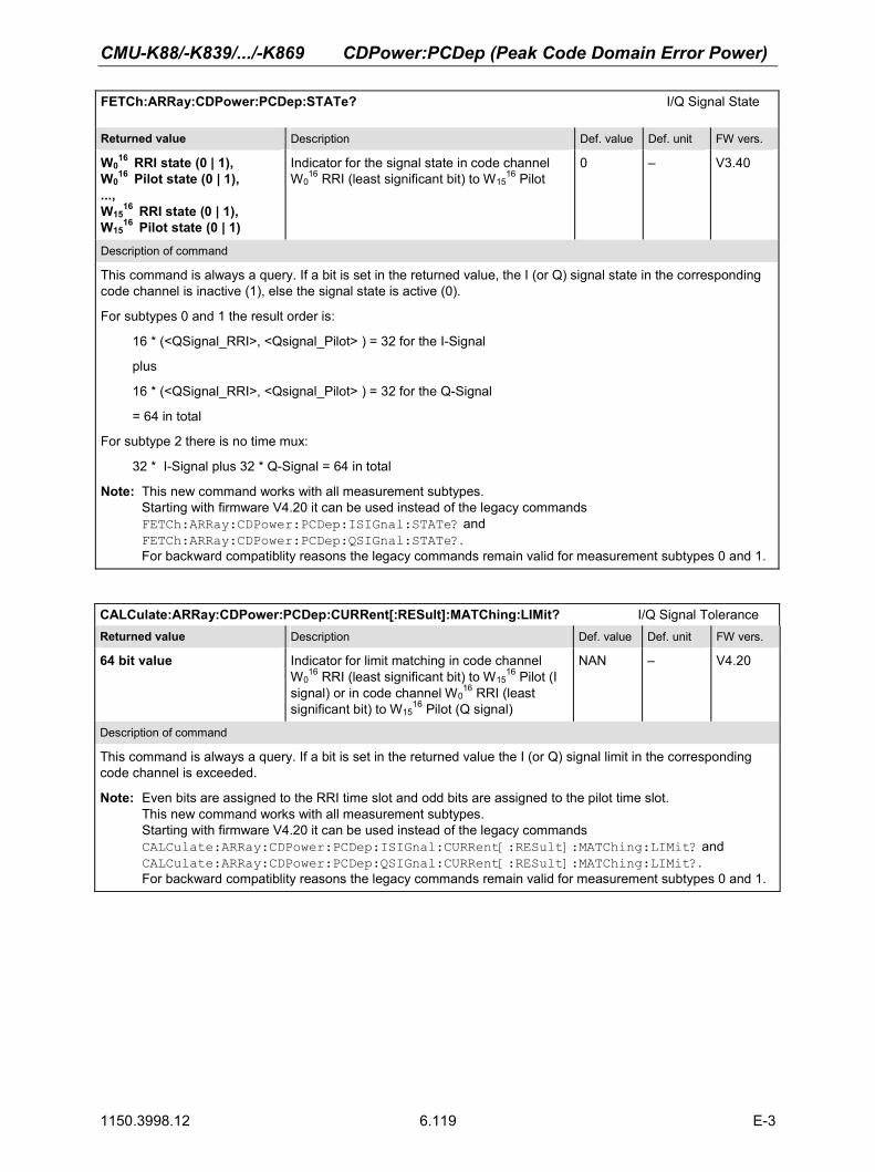
CMU-K88/-K839/.../-K869 CDPower:PCDep (Peak Code Domain Error Power)
1150.3998.12 6.119 E-3
FETCh:ARRay:CDPower:PCDep:STATe? I/Q Signal State Returned value Description Def. value Def. unit FW vers.
W016 RRI state (0 | 1),
W016 Pilot state (0 | 1),
..., W15
16 RRI state (0 | 1), W15
16 Pilot state (0 | 1)
Indicator for the signal state in code channel W0
16 RRI (least significant bit) to W1516 Pilot
0 – V3.40
Description of command
This command is always a query. If a bit is set in the returned value, the I (or Q) signal state in the corresponding code channel is inactive (1), else the signal state is active (0).
For subtypes 0 and 1 the result order is:
16 * (<QSignal_RRI>, <Qsignal_Pilot> ) = 32 for the I-Signal
plus
16 * (<QSignal_RRI>, <Qsignal_Pilot> ) = 32 for the Q-Signal
= 64 in total
For subtype 2 there is no time mux:
32 * I-Signal plus 32 * Q-Signal = 64 in total
Note: This new command works with all measurement subtypes. Starting with firmware V4.20 it can be used instead of the legacy commands FETCh:ARRay:CDPower:PCDep:ISIGnal:STATe? and FETCh:ARRay:CDPower:PCDep:QSIGnal:STATe?.For backward compatiblity reasons the legacy commands remain valid for measurement subtypes 0 and 1.
CALCulate:ARRay:CDPower:PCDep:CURRent[:RESult]:MATChing:LIMit? I/Q Signal Tolerance Returned value Description Def. value Def. unit FW vers.
64 bit value Indicator for limit matching in code channel W0
16 RRI (least significant bit) to W1516 Pilot (I
signal) or in code channel W016 RRI (least
significant bit) to W1516 Pilot (Q signal)
NAN – V4.20
Description of command
This command is always a query. If a bit is set in the returned value the I (or Q) signal limit in the corresponding code channel is exceeded.
Note: Even bits are assigned to the RRI time slot and odd bits are assigned to the pilot time slot. This new command works with all measurement subtypes. Starting with firmware V4.20 it can be used instead of the legacy commands CALCulate:ARRay:CDPower:PCDep:ISIGnal:CURRent[:RESult]:MATChing:LIMit? and CALCulate:ARRay:CDPower:PCDep:QSIGnal:CURRent[:RESult]:MATChing:LIMit?.For backward compatiblity reasons the legacy commands remain valid for measurement subtypes 0 and 1.

CDPower:CHPW (Channel Power) CMU-K88/-K839/.../-K869
1150.3998.12 6.120 E-3
CALCulate:ARRay:CDPower:PCDep:AVERage[:RESult]:MATChing:LIMit? I/Q Signal Tolerance Returned value Description Def. value Def. unit FW vers.
64 bit value Indicator for limit matching in code channel W0
16 RRI (least significant bit) to W1516 Pilot (I
signal) or in code channel W016 RRI (least
significant bit) to W1516 Pilot (Q signal)
NAN – V4.20
Description of command
This command is always a query. If a bit is set in the returned value the I (or Q) signal limit in the corresponding code channel is exceeded.
Note: Even bits are assigned to the RRI time slot and odd bits are assigned to the pilot time slot. This new command works with all measurement subtypes. Starting with firmware V4.20 it can be used instead of the legacy commands CALCulate:ARRay:CDPower:PCDep:ISIGnal:AVERage[:RESult]:MATChing:LIMit? and CALCulate:ARRay:CDPower:PCDep:QSIGnal:AVERage[:RESult]:MATChing:LIMit?.For backward compatiblity reasons the legacy commands remain valid for measurement subtypes 0 and 1.
CALCulate:ARRay:CDPower:PCDep:MAXimum[:RESult]:MATChing:LIMit? I/Q Signal Tolerance Returned value Description Def. value Def. unit FW vers.
64 bit value Indicator for limit matching in code channel W0
16 RRI (least significant bit) to W1516 Pilot (I
signal) or in code channel W016 RRI (least
significant bit) to W1516 Pilot (Q signal)
NAN – V4.20
Description of command
This command is always a query. If a bit is set in the returned value the I (or Q) signal limit in the corresponding code channel is exceeded.
Note: Even bits are assigned to the RRI time slot and odd bits are assigned to the pilot time slot. This new command works with all measurement subtypes. Starting with firmware V4.20 it can be used instead of the legacy commands CALCulate:ARRay:CDPower:PCDep:ISIGnal:MAXimum[:RESult]:MATChing:LIMit? and CALCulate:ARRay:CDPower:PCDep:QSIGnal:MAXimum[:RESult]:MATChing:LIMit?.For backward compatiblity reasons the legacy commands remain valid for measurement subtypes 0 and 1.
CDPower:CHPW (Channel Power) The subsystem CDPower:CHPW measures the Channel Power ouput. The subsystem corresponds to the measurement menu Code Domain Power, application Channel Power, and the sections related to this application in the associated popup menu Code Domain Power Configuration. Control of measurement
The subsystem CDPower:CHPW controls the channel power measurement. It corresponds to the softkey ChP in the measurement menu Code Domain Power.
INITiate:CDPower:CHPW Start new measurement ⇒ RUN ABORt:CDPower:CHPW Abort running measurement and switch off ⇒ OFF STOP:CDPower:CHPW Stop measurement after current stat. cycle ⇒ STOP CONTinue:CDPower:CHPW Next measurement step (stepping mode) ⇒ RUN Description of command FW vers.
These commands have no query form. They start and stop the channel power measurement, setting it to the status indicated in the top right column.
V3.40

CMU-K88/-K839/.../-K869 CDPower:CHPW (Channel Power)
1150.3998.12 6.121 E-3
CONFigure:CDPower:CHPW:EREPorting[?] Event Reporting <Report Mode><Report Mode> Description of parameters Def. value Def. unit FW vers.
SRQ | SOPC | SRSQ | OFF | DEFault
Service request Single operation complete SRQ and SOPC No reporting Sets the value to the default setting
OFF – V3.40
Description of command
This command defines the events generated when the measurement is terminated or stopped (see Event Reporting in chapter 5 of the CMU 200/300 manual).
FETCh[:SCALar]:CDPower:CHPW:STATus? Measurement Status <MeasurementStatus>, <Curr.Step.CycleCount>, <ElapsedStatistics> <Meas.Status> Description of parameters Def. value Def. unit FW vers.
OFF | RUN | STOP | ERR | STEP | RDY
Measurement in the OFF state (*RST or ABORt) Running (after INITiate, CONTinue or READ) Stopped (STOP) OFF (could not be started) Stepping mode (<stepmode>=STEP) Stopped according to repetition mode and stop condition
OFF – V3.40
<Cycle Count> Description of parameters Def. value Def. unit FW vers.
1 to 10000 | NONE
Counter for current statistics cycle No counting mode set
NONE – V3.40
<ElapsedStatistics> Description of parameters Def. value Def. unit FW vers.
1 to 1000 NONE
Counter for current evaluation period within a cycle Statistic count set to off
NONE – V3.40
Description of command
This command is always a query. It returns the status of the measurement (see chapters 3 and 5).
Test Configuration
The commands of the following subsystems configure the Channel Power measurement in the Code Domain Power menu. They correspond to the Code Domain Power Configuration popup menu.
Subsystem CONTrol
The subsystem CDPower:CHPW:CONTrol defines the result mode, repetition mode, statistic count and stop condition of the measurement. These settings are provided in the Control tab in the popup menu Code Domain Power Configuration.

CDPower:CHPW (Channel Power) CMU-K88/-K839/.../-K869
1150.3998.12 6.122 E-3
CONFigure:CDPower:CHPW:CONTrol[?] Scope of Measurement <Result Mode>, <Current Statistics>, <Repetition>, <Stop Cond>, <Step Mode> <Result Mode> Description of parameters Def. value Def. unit FW-Vers.
SCALar | ARRay,
Scalar values only (incl. ramp matching) Scalar measured values and arrays
ARR – V3.40
<Current Statistics> Description of parameters Def. value Def. unit FW-Vers.
1 to 1000, Number of bursts per statistics cycle 100 – V3.40
<Repetition> Description of parameters Def. value Def. unit FW-Vers.
1 to 10000 | CONTinuous | SINGleshot | DEFault,
Multiple measurement (counting, until Status = STEP | RDY) Continuous measurement (until STOP or ABORT) Single shot measurement (until Status = RDY) Sets the value to the default setting
SING – V3.40
<Stop Cond> Description of parameters Def. value Def. unit FW-Vers.
NONE | SONerror | DEFault,
Continue measurement even in case of error Stop measurement in case of error (stop on error) Sets the value to the default setting
NONE – V3.40
<Step Mode> Description of parameters Def. value Def. unit FW-Vers.
STEP | NONE | DEFault
Interrupt measurement after each statistics cycle Continue measurement according to its rep. Mode Sets the value to the default setting
NONE – V3.40
Description of command
This command combines the ...CONTrol:RMODe,...CONTrol:STATistics and the ...CONTrol:REPetition commands, see below.
CONFigure:CDPower:CHPW:CONTrol:RMODe[?] Result Mode <Result Mode> <Result Mode> Description of parameters Def. value Def. unit FW-Vers.
SCALar | ARRay
Scalar values only (incl. ramp matching) Scalar measured values and arrays
ARR – V3.40
Description of command
This command specifies the type of measured values.
CONFigure:CDPower:CHPW:CONTrol:STATistics[?] Statistic Count <Current Statistics > <Current Statistics> Description of parameters Def. value Def. unit FW-Vers.
1 to 1000 Number of bursts per statistics cycle 100 – V3.40
Description of command
This command defines the number of bursts forming a statistics cycle.

CMU-K88/-K839/.../-K869 CDPower:CHPW (Channel Power)
1150.3998.12 6.123 E-3
CONFigure:CDPower:CHPW:CONTrol:REPetition[?] Test Cycles <Repetition>, <Stop Cond>, <Step Mode> <Repetition> Description of parameters Def. value Def. unit FW vers.
1 to 10000 | CONTinuous | SINGleshot | DEFault,
Multiple measurement (counting, until Status = STEP | RDY) Continuous measurement (until STOP or ABORT) Single shot measurement (until Status = RDY) Sets the value to the default setting
SING – V3.40
<Stop Cond> Description of parameters Def. value Def. unit FW vers.
NONE | SONerror | DEFault,
Continue measurement even in case of error Stop measurement in case of error (stop on error) Sets the value to the default setting
NONE – V3.40
<Step Mode> Description of parameters Def. value Def. unit FW vers.
STEP | NONE | DEFault
Interrupt measurement after each statistics cycle Continue measurement according to its rep. Mode Sets the value to the default setting
NONE – V3.40
Description of command
This command determines the repetition mode, stop condition, and stepping mode for the measurement.
Note: In the case of READ commands (READ:...), the <Repetition> parameter has no effect; the measurement is always stopped after a single shot.
CONFigure:CDPower:CHPW:CONTrol:PRMode[?] Reference Power Mode <ReferencePowerMode> <Ref.PowerMode> Description of parameters Def. value Def. unit FW vers.
ATPower | PPOWer
Activate the AT power mode Activate the pilot power mode
ATP
– V4.20
Description of command
This command sets the reference power mode for the measurement, either pilot power or AT power measurement mode.
If used as a query the command returns the currently set reference power mode.
DEFault:CDPower:CHPW:CONTrol[?] Default Settings <Enable> Description of parameters Def. value Def. unit FW vers.
ON | OFF
The parameters are set to their default values Some or all parameters are not set to default
ON
– V3.40
Description of command
If used as a setting command with the parameter ON, this command sets all parameters of the subsystem CDPower:CHPW:CONTrol to their default values (the setting OFF results in an error message).
If used as a query the command returns whether all parameters are set to their default values (ON) or not (OFF).

CDPower:CHPW (Channel Power) CMU-K88/-K839/.../-K869
1150.3998.12 6.124 E-3
Subsystem LIMit
CDPower:CPCCommon:LIMit
The subsystem CDPower:CPCCommon:LIMit defines common tolerance values for the scalar results of the CPCCommon Code Domain Power applications. These commands are described in on page 6.103.
CDPower:CHPW:LIMit
The subsystem CDPower:CHPW:LIMIT defines the tolerance values that apply to the Channel Power application only. CONFigure:CDPower:CHPW:CMAX:LIMit:ASYMmetric[:COMBined][?] Limits <CHPW Limit Y> <CHPW Limit Y> Description of parameters Def. value Def. unit FW vers.
–60.0 to 0 | DEFault | MINimum | MAXimum | OFF
Channel power Y limit Sets the value to the default setting Sets the value to the minimum range value Sets the value to the maximum range value Disables the tolerance check
–23.0 dB
V3.40
Description of command
This command defines the upper limit for the channel power (Y value). The keywords CMAX and AVERage refer to the Current and Max. display and for the Average display, respectively.
CONFigure:CDPower:CHPW:AVERage:LIMit:ASYMmetric[:COMBined][?] Limits <CHPW Limit Y Average> <CHPW Limit Y Average> Description of parameters Def. value Def. unit FW vers.
–60.0 to 0 | DEFault | MINimum | MAXimum | OFF
Channel power Y limit Sets the value to the default setting Sets the value to the minimum range value Sets the value to the maximum range value Disables the tolerance check
–23.0 dB
V3.40
Description of command
This command defines the upper limit for the channel power (Y value). The keywords CMAX and AVERage refer to the Current and Max. display and for the Average display, respectively.
DEFault:CDPower:CHPW:LIMit[?] Default Settings <Enable>Enable Description of parameters Def. value Def. unit FW vers.
ON | OFF
The parameters are set to their default values Some or all parameters are not set to default
ON
– V3.40
Description of command
If used as a setting command with the parameter ON, this command sets all parameters of the subsystem CDPower:CHPW:LIMit to their default values (the setting OFF results in an error message).
If used as a query, the command returns whether all parameters are set to their default values (ON) or not (OFF).

CMU-K88/-K839/.../-K869 CDPower:CHPW (Channel Power)
1150.3998.12 6.125 E-3
Measured Values
The subsystem CDPower:CHPW determines and outputs the results of the Channel Power measurement. XTND:CDPower:CHPW:RESult:DATa[?] Data Channel Result Extension <Enable> Description of parameters Def. value Def. unit FW vers.
ON | OFF | DEFault
Data Channel Result Extension enabled Data Channel Result Extension disabled Result Extension is set to default value
OFF
– V4.31
Description of command
If used as a setting command with the parameter ON, this command defines the result set of the READ ( or FETCh or SAMPle):ARRay:CDPower:CHPW[:VALue]:CURRent (or AVERage or MAXimum) command responses. The different result sets are described below.
If used as a query the command returns whether all parameters are set to their default values (ON) or not (OFF).
Scalar results: READ[:SCALar]:CDPower:CHPW? Start single shot measurement and return results FETCh[:SCALar]:CDPower:CHPW? Read out measurement results (unsynchronized) SAMPle[:SCALar]:CDPower:CHPW? Read out measurement results (synchronized) Returned values Value range Def. value Def. unit FW vers.
AT Power (x3), Carrier Feedthrough (x3),Carrier Freq. Error (x3), Rho (x3), Out of Tolerance, Current Statistics
–100.0 dBm to –50.0 dBm –120.0 dB to –20.0 dB 0 to 1000.0 Hz 0.0 to 1.0 0.0% to 100.0% 1 to 1000
NAN NAN NAN NAN NAN NAN
dBm dB Hz –%–
V3.40
Description of command
These commands are always queries. They start a measurement and output all scalar measurement results. The symbol (x3) behind a value indicates that the list contains three results corresponding to the Current, the Average, and the MMax value.
CALCulate[:SCALar]:CDPower:CHPW:MATChing:LIMit? Limit Matching Returned values Value range Def. value Def. unit FW vers.
Carrier Feedthrough (x3),Carrier Freq. Error (x3), Rho (x3)
For all values NMAU | NMAL | INV | OK
INV INV INV
–––
V3.40
Description of command
This command is always a query. It indicates whether and in which way the (fixed) limit lines have been exceeded. The symbol (x3) behind a value indicates that the list contains three results corresponding to the Current, the Average, and the MMax value. The following messages may be generated:
NMAU Tolerance value underflow not matching, underflow NMAL Tolerance value exceeded not matching, overflow INV Measurement invalid invalid
OK Tolerance value matched

CDPower:CHPW (Channel Power) CMU-K88/-K839/.../-K869
1150.3998.12 6.126 E-3
I/Q Signal Measurement READ:ARRay:CDPower:CHPW[:VALue]:CURRent? Start single shot meas. and return results FETCh:ARRay:CDPower:CHPW[:VALue]:CURRent? Read meas. results (unsynchronized) SAMPle:ARRay:CDPower:CHPW[:VALue]:CURRent? Read results (synchronized) Returned values Value range Def. value Def. unit FW vers.
For measurement subtypes 0:
W416 RRI,
W016 Pilot,
W1232 ACK,
W816 DRC,
W24 Data
–60.0 dB to +10.0 dB, –60.0 dB to +10.0 dB, –60.0 dB to +10.0 dB, –60.0 dB to +10.0 dB, –60.0 dB to +10.0 dB
NAN dB V4.20
For measurement subtype 2:
W416 RRI,
W016 Pilot,
W1232 ACK/DSC,
W28
32 AuxPilot, W8
16 DRC, W2
4 Data Channel
–60.0 dB to +10.0 dB, –60.0 dB to +10.0 dB, –60.0 dB to +10.0 dB (depending on Code Channel Filter setting), –60.0 dB to +10.0 dB, –60.0 dB to +10.0 dB, –60.0 dB to +10.0 dB
NAN dB V4.20
For measurement subtype 2 with extended result list (XTND:CDPower:CHPW:RESult:DATa ON):
W416 RRI,
W016 Pilot,
W1232 ACK/DSC,
W28
32 AuxPilot, W8
16 DRC, W2
4 Data Channel, W2
4- I Data Channel, W2
4-Q Data Channel, W1
4- I Data Channel, W1
4-Q Data Channel, Reserved, Reserved
–60.0 dB to +10.0 dB, –60.0 dB to +10.0 dB, –60.0 dB to +10.0 dB (depending on Code Channel Filter setting), –60.0 dB to +10.0 dB, –60.0 dB to +10.0 dB, –60.0 dB to +10.0 dB, –60.0 dB to +10.0 dB, –60.0 dB to +10.0 dB, –60.0 dB to +10.0 dB, –60.0 dB to +10.0 dB NAN NAN
NAN dB V4.31
Description of command
These commands are always queries.
In the context of measurement subtype 0, they start a measurement and return the five levels of the RRI, Pilot, ACK, DRC, and Data channels.
In the context of measurement subtype 2, they start a measurement and return the six levels of the RRI, Pilot, ACK/DSC (depending on Code Channel Filter), AuxPilot, DRC, and Data channels. If XTND:CDPower:CHPW:RESult:DATa is enabled, the subtype 2 result is extended by the W2
4 and W14 I/Q
values of the Data channel.
The calculation of Current is explained in chapter 3 (see display mode).
Note: These new commands work with all measurement subtypes as described above. Starting with firmware V4.20 it can be used instead of the legacy commands READ:ARRay:CDPower:CHPW:ISIGnal[:VALue]:CURRent?,READ:ARRay:CDPower:CHPW:QSIGnal[:VALue]:CURRent?,FETCh:ARRay:CDPower:CHPW:ISIGnal[:VALue]:CURRent?,FETCh:ARRay:CDPower:CHPW:QSIGnal[:VALue]:CURRent?,SAMPle:ARRay:CDPower:CHPW:ISIGnal[:VALue]:CURRent?, and SAMPle:ARRay:CDPower:CHPW:QSIGnal[:VALue]:CURRent?.For backward compatiblity reasons the legacy commands remain valid for measurement subtypes 0 and 1.

CMU-K88/-K839/.../-K869 CDPower:CHPW (Channel Power)
1150.3998.12 6.127 E-3
I/Q Signal Measurement READ:ARRay:CDPower:CHPW[:VALue]:AVERage? Start single shot meas. and return results FETCh:ARRay:CDPower:CHPW[:VALue]:AVERage? Read meas. results (unsynchronized) SAMPle:ARRay:CDPower:CHPW[:VALue]:AVERage? Read results (synchronized) Returned values Value range Def. value Def. unit FW vers.
For measurement subtype 0:
W416 RRI,
W016 Pilot,
W1232 ACK,
W816 DRC,
W24 Data
–60.0 dB to +10.0 dB, –60.0 dB to +10.0 dB, –60.0 dB to +10.0 dB, –60.0 dB to +10.0 dB, –60.0 dB to +10.0 dB
NAN dB V4.20
For measurement subtype 2:
W416 RRI,
W016 Pilot,
W1232 ACK/DSC,
W28
32 AuxPilot, W8
16 DRC, W2
4 Data Channel
–60.0 dB to +10.0 dB, –60.0 dB to +10.0 dB, –60.0 dB to +10.0 dB (depending on Code Channel Filter setting), –60.0 dB to +10.0 dB, –60.0 dB to +10.0 dB, –60.0 dB to +10.0 dB
NAN dB V4.20
For measurement subtype 2 with extended result list (XTND:CDPower:CHPW:RESult:DATa ON):
W416 RRI,
W016 Pilot,
W1232 ACK/DSC,
W28
32 AuxPilot, W8
16 DRC, W2
4 Data Channel, W2
4- I Data Channel, W2
4-Q Data Channel, W1
4- I Data Channel, W1
4-Q Data Channel, Reserved, Reserved
–60.0 dB to +10.0 dB, –60.0 dB to +10.0 dB, –60.0 dB to +10.0 dB (depending on Code Channel Filter setting), –60.0 dB to +10.0 dB, –60.0 dB to +10.0 dB, –60.0 dB to +10.0 dB, –60.0 dB to +10.0 dB, –60.0 dB to +10.0 dB, –60.0 dB to +10.0 dB, –60.0 dB to +10.0 dB NAN NAN
NAN dB V4.31
Description of command
These commands are always queries.
In the context of measurement subtypes 0, they start a measurement and return the five levels of the RRI, Pilot, ACK, DRC, and Data channels.
In the context of measurement subtype 2, they start a measurement and return the six levels of the RRI, Pilot, ACK/DSC (depending on Code Channel Filter), AuxPilot, DRC, and Data channels. If XTND:CDPower:CHPW:RESult:DATa is enabled, the subtype 2 result is extended by the W2
4 and W14 I/Q
values of the Data channel.
The calculation of Average is explained in chapter 3 (see display mode).
Note: These new commands work with all measurement subtypes as described above. Starting with firmware V4.20 it can be used instead of the legacy commands READ:ARRay:CDPower:CHPW:ISIGnal[:VALue]:AVERage?,READ:ARRay:CDPower:CHPW:QSIGnal[:VALue]:AVERage?,FETCh:ARRay:CDPower:CHPW:ISIGnal[:VALue]:AVERage?,FETCh:ARRay:CDPower:CHPW:QSIGnal[:VALue]:AVERage?,SAMPle:ARRay:CDPower:CHPW:ISIGnal[:VALue]:AVERage?, and SAMPle:ARRay:CDPower:CHPW:QSIGnal[:VALue]:AVERage?.For backward compatiblity reasons the legacy commands remain valid for measurement subtype 0.

CDPower:CHPW (Channel Power) CMU-K88/-K839/.../-K869
1150.3998.12 6.128 E-3
I/Q Signal Measurement READ:ARRay:CDPower:CHPW[:VALue]:MAXimum? Start single shot meas. and return results FETCh:ARRay:CDPower:CHPW[:VALue]:MAXimum? Read meas. results (unsynchronized) SAMPle:ARRay:CDPower:CHPW[:VALue]:MAXimum? Read results (synchronized) Returned values Value range Def. value Def. unit FW vers.
For measurement subtype 0:
W416 RRI,
W016 Pilot,
W48 ACK,
W816 DRC,
W24 Data
–60.0 dB to +10.0 dB, –60.0 dB to +10.0 dB, –60.0 dB to +10.0 dB, –60.0 dB to +10.0 dB, –60.0 dB to +10.0 dB
NAN dB V4.20
For measurement subtype 2:
W416 RRI,
W016 Pilot,
W1232 ACK/DSC,
W28
32 AuxPilot, W8
16 DRC, W2
4 Data Channel
–60.0 dB to +10.0 dB, –60.0 dB to +10.0 dB, –60.0 dB to +10.0 dB (depending on Code Channel Filter setting), –60.0 dB to +10.0 dB, –60.0 dB to +10.0 dB, –60.0 dB to +10.0 dB
NAN dB V4.20
For measurement subtype 2 with extended result list (XTND:CDPower:CHPW:RESult:DATa ON):
W416 RRI,
W016 Pilot,
W1232 ACK/DSC,
W28
32 AuxPilot, W8
16 DRC, W2
4 Data Channel, W2
4- I Data Channel, W2
4-Q Data Channel, W1
4- I Data Channel, W1
4-Q Data Channel, Reserved, Reserved
–60.0 dB to +10.0 dB, –60.0 dB to +10.0 dB, –60.0 dB to +10.0 dB (depending on Code Channel Filter setting), –60.0 dB to +10.0 dB, –60.0 dB to +10.0 dB, –60.0 dB to +10.0 dB, –60.0 dB to +10.0 dB, –60.0 dB to +10.0 dB, –60.0 dB to +10.0 dB, –60.0 dB to +10.0 dB, NAN, NAN
NAN dB V4.31
Description of command
These commands are always queries.
In the context of measurement subtype 0, they start a measurement and return the five levels of the RRI, Pilot, ACK, DRC, and Data channels.
In the context of measurement subtype 2, they start a measurement and return the six levels of the RRI, Pilot, ACK/DSC (depending on Code Channel Filter), AuxPilot, DRC, and Data channels.
If XTND:CDPower:CHPW:RESult:DATa is enabled, the subtype 2 result is extended by the W24 and W1
4 I/Q values of the Data channel.
The calculation of Maximum is explained in chapter 3 (see display mode).
Note: These new commands work with all measurement subtypes as described above. Starting with firmware V4.20 it can be used instead of the legacy commands READ:ARRay:CDPower:CHPW:ISIGnal[:VALue]:MAXimum?, READ:ARRay:CDPower:CHPW:QSIGnal[:VALue]:MAXimum?, FETCh:ARRay:CDPower:CHPW:ISIGnal[:VALue]:MAXimum?, FETCh:ARRay:CDPower:CHPW:QSIGnal[:VALue]:MAXimum?, SAMPle:ARRay:CDPower:CHPW:ISIGnal[:VALue]:MAXimum?, and SAMPle:ARRay:CDPower:CHPW:QSIGnal[:VALue]:MAXimum?.For backward compatiblity reasons the legacy commands remain valid for measurement subtype 0.

CMU-K88/-K839/.../-K869 CDPower:CHPW (Channel Power)
1150.3998.12 6.129 E-3
FETCh:ARRay:CDPower:CHPW:STATe? I/Q Signal State Returned value Description Def. value Def. unit FW vers.
For measurement subtype 0:
RRI state Pilot state ACK state DRC state Data state
Indicator for state in: W4
16 RRI bit 0 W0
16 Pilot bit 1 W12
32 ACK bit 2 W8
16 DRC bit 0 W2
4 Data bit 1 (bit 0 is the least significant)
NAN – V4.20
For measurement subtype 2:
RRI state Pilot state ACK/DSC state AuxPilot state DRC state Data state
Indicator for state in: W4
16 RRI bit 0 W0
16 Pilot bit 1 W12
32 ACK/DSC bit 2 W28
32 AuxPilot W8
16 DRC bit 0 W2
4 Data bit 1 (bit 0 is the least significant)
NAN – V4.20
Description of command
This command is always a query. If a bit is set in the returned value, the I (or Q) signal state in the corresponding code channel is inactive, else the signal state is active.
Note: This new command works with all measurement subtypes. Starting with firmware V4.20 it can be used instead of the legacy commands FETCh:ARRay:CDPower:CHPW:ISIGnal:STATe?, and FETCh:ARRay:CDPower:CHPW:QSIGnal:STATe?.For backward compatiblity reasons the legacy commands remain valid for measurement subtype 0.

CDPower:CHPW (Channel Power) CMU-K88/-K839/.../-K869
1150.3998.12 6.130 E-3
CALCulate:ARRay:CDPower:CHPW:CURRent[:RESult]:MATChing:LIMit? I/Q Signal Tolerance Returned value Description Def. value Def. unit FW vers.
For measurement subtype 0:
64 bit value
ToleranceBitField for I signal W0
16 RRI bit 0 W0
16 Pilot bit 1 W4
8 ACK bit 2 ToleranceBitField for Q signal W8
16 DRC bit 0 W2
4 Data bit 1 (bit 0 is the least significant)
NAN – V4.20
For measurement subtype 2:
64 bit value ToleranceBitField for all channels W0
16 RRI bit 0 W0
16 Pilot bit 1 W4
8 ACK/DSC bit 2 (depending on Code Channel Filter setting) W28
32 AuxPilot W8
16 DRC bit 0 W2
4 Data bit 1 (bit 0 is the least significant)
NAN – V4.20
Description of command
This command is always a query. If a bit is set in the returned value the I (or Q) signal limit in the corresponding code channel is exceeded.
Note: This new command works with all measurement subtypes as described above. Starting with firmware V4.20 it can be used instead of the legacy commands CALCulate:ARRay:CDPower:CHPW:ISIGnal:CURRent[:RESult]:MATChing:LIMit?, and CALCulate:ARRay:CDPower:CHPW:QSIGnal:CURRent[:RESult]:MATChing:LIMit?.For backward compatiblity reasons the legacy commands remain valid for measurement subtype 0.

CMU-K88/-K839/.../-K869 CDPower:CHPW (Channel Power)
1150.3998.12 6.131 E-3
CALCulate:ARRay:CDPower:CHPW:AVERage[:RESult]:MATChing:LIMit? I/Q Signal Tolerance Returned value Description Def. value Def. unit FW vers.
For measurement subtypes 0:
64 bit value
ToleranceBitField for I signal W0
16 RRI bit 0 W0
16 Pilot bit 1 W4
8 ACK bit 2 ToleranceBitField for Q signal W8
16 DRC bit 0 W2
4 Data bit 1 (bit 0 is the least significant)
NAN – V4.20
For measurement subtype 2:
64 bit value ToleranceBitField for all channels W0
16 RRI bit 0 W0
16 Pilot bit 1 W4
8 ACK/DSC bit 2 (depending on Code Channel Filter setting) W28
32 AuxPilot W8
16 DRC bit 0 W2
4 Data bit 1 (bit 0 is the least significant)
NAN – V4.20
Description of command
This command is always a query. If a bit is set in the returned value the I (or Q) signal limit in the corresponding code channel is exceeded.
Note: This new command works with all measurement subtypes as described above. Starting with firmware V4.20 it can be used instead of the legacy commands CALCulate:ARRay:CDPower:CHPW:ISIGnal:AVERage[:RESult]:MATChing:LIMit?, and CALCulate:ARRay:CDPower:CHPW:QSIGnal:AVERage[:RESult]:MATChing:LIMit?.For backward compatiblity reasons the legacy commands remain valid for measurement subtype 0.

CDPower:CHPW (Channel Power) CMU-K88/-K839/.../-K869
1150.3998.12 6.132 E-3
CALCulate:ARRay:CDPower:CHPW:MAXimum[:RESult]:MATChing:LIMit? I/Q Signal Tolerance Returned value Description Def. value Def. unit FW vers.
For measurement subtypes 0:
64 bit value
ToleranceBitField for I signal W0
16 RRI bit 0 W0
16 Pilot bit 1 W4
8 ACK bit 2 ToleranceBitField for Q signal W8
16 DRC bit 0 W2
4 Data bit 1 (bit 0 is the least significant)
NAN – V4.20
For measurement subtype 2:
64 bit value ToleranceBitField for all channels W0
16 RRI bit 0 W0
16 Pilot bit 1 W4
8 ACK/DSC bit 2 (depending on Code Channel Filter setting) W28
32 AuxPilot W8
16 DRC bit 0 W2
4 Data bit 1 (bit 0 is the least significant)
NAN – V4.20
Description of command
This command is always a query. If a bit is set in the returned value the I (or Q) signal limit in the corresponding code channel is exceeded.
Note: This new command works with all measurement subtypes as described above. Starting with firmware V4.20 it can be used instead of the legacy commands CALCulate:ARRay:CDPower:CHPW:ISIGnal:MAXimum[:RESult]:MATChing:LIMit?, and CALCulate:ARRay:CDPower:CHPW:QSIGnal:MAXimum[:RESult]:MATChing:LIMit?.For backward compatiblity reasons the legacy commands remain valid for measurement subtype 0.

CMU-K88/-K839/.../-K869 Measurement Command Groups (Signaling Only)
1150.3998.12 6.133 E-3
Measurement Command Groups (Signaling Only) In the Signaling mode, the CMU is able to generate control and traffic channel signals and to set up a call to the Access Terminal. A broad range of signaling parameters can be configured and measure-ments may be performed with a call connection established. RxQuality (Receiver Quality)
Receiver Quality measurements provide a wide range of parameters to characterize the connectivity of the forward and reverse link. The parameters are described in the specification C.S0029-A. The Re-ceiver Quality measurements and the results are in accordance with the definitions of the specification.
The subsystem RXQuality comprises the commands for all receiver quality measurements. The subsys-tem corresponds to the main menu Receiver Quality and the associated popup menu Receiver Quality Configuration.
Control of Measurement - Common Commands
Here the common settings for all Receiver Quality measurement applications are described. CONFigure:UPERiod[?] Update Period <Update Period> <Update Rate> Description of parameters Def. value Def. unit FW vers.
0.2 s to 2.0 s | MINimum | MAXimum | DEFault
Update period of the receiver quality test applications Sets the minimum update period Sets the maximum update period Use default settings
1.0
s V4.20
Description of command
This command determines the update period of the receiver quality test applications (absolute value, in seconds).
Note: To reset the statics of the RXQ measurements, send the command: INITiate:LAYer:APPLication:TEST:STATistics (from the Sign. - LAYer subsystem)
Note: This command replaces the legacy command CONFigure:RXQuality:UPERiod[?], but the old syntax can still be used for compatibility reasons. The command is identical with the one described on p. 6.152.
DEFault:RXQuality:CONTrol[?] RxQuality Control <Enable> <Enable> Description of parameters Def. Value Def. unit FW vers.
ON | OFF
The CONF:RXQ:<Application>:Control:<…> and CONF:RXQ:URATe commands are set to their default valuesQuery whether or not the RxQuality test application parame-ters are set to their default values (query only)
ON – V4.20
Description of command
This command resets all values for the receiver quality test applications to default. OFF is a query only.

Measurement Command Groups (Signaling Only) CMU-K88/-K839/.../-K869
1150.3998.12 6.134 E-3
DEFault:RXQuality:LIMit[?] RxQuality Limits <Default RxQuality LIMit subsystem> <Enable> Description of parameters Def. Value Def. unit FW vers.
ON | OFF
The CONF:RXQ:<Application>:Limit:<…> commands are set to their default values Query whether or not the RxQuality test application limit parameters are set to their default values (query only)
ON – V4.20
Description of command
This command resets all limit values for the receiver quality test applications to default. OFF is a query only.
Test Configuration
Statistics Overview Application
The Statistics Overview measurement gives an overview of all Receiver Quality measurements and their statistics. In remote control, only a single command retrieving all results is needed. Measured Values
The subsystem RXQuality:SOVerview determines and outputs the results of the Receiver Quality statis-tics measurement. [SENSe:][SCALar:]RXQuality:SOVerview? Statistics overview results Returned values: Value range Def. value Def. unit FW vers.
<Received Packets for …>
Control Channel PER, Forward Link PER, Reverse Link Quality, Reverse Link PER, Forward Link Performance, Forward Link Perf. vs. Slot, Reverse Link Performance,
0 to 1,000 (packets) 0 to 100,000 (packets) 0 to 100,000 (packets) 0 to 10,000 (packets) 0 to 10,000 (frames) 0 to 10,000 (frames)
NAN – ––––––
V4.20
<Denominators for …>
Control Channel PER, Forward Link PER, Reverse Link Quality, Reverse Link PER, Forward Link Performance, Forward Link Perf. vs. Slot, Reverse Link Performance,
1 to 1,000 (packets) 1 to 100,000 (packets) 1 to 100,000 (packets) 1 to 10,000 (packets) 1 to 10,000 (frames) 1 to 10,000 (frames)
NAN – ––––––
V4.20
<Results for …>
Control Channel PER, Forward Link PER, Reverse Link Quality, Reverse Link PER, Forward Link Performance, Forward Link Perf. vs. Slot, Reverse Link Performance,
0.0 to 100.0 % 0.0 to 100.0 % 0.0 to 100.0 % 0.0 to 100.0 % 0.0 to 3072.0 kBit/s 0.0 to 1843.6 kBit/s 0.0 to 153.6 kBit/s
NAN % %%%kBit/s kBit/s kBit/s
V4.20
Description of command
This commands is always a query. It returns all current Statistics Overview results.

CMU-K88/-K839/.../-K869 Measurement Command Groups (Signaling Only)
1150.3998.12 6.135 E-3
Control Channel PER Application
INITiate:RXQuality:CCPer Start new measurement ⇒ RUNABORt:RXQuality:CCPer Abort measurement and switch off ⇒ OFFSTOP:RXQuality:CCPer Stop measurement ⇒ STOP
Description of command FW vers.
These commands have no query form. They start or stop the receiver quality control channel PER measurements.
V4.20
CONFigure:RXQuality:CCPer:EREPorting[?] Event Reporting <ReportMode>
<ReportMode> Description of parameters Def. value Def. unit FW vers.
SRQ | SOPC | SRSQ | OFF | DEFault
Service request Single operation complete SRQ and SOPC No reporting Sets the value to the default setting
OFF – V4.20
Description of command
This command defines the events generated when the control channel PER measurement is terminated or stopped (event reporting, see chapter 5 of CMU 200/300 operating manual).
FETCh[:SCALar]:RXQuality:CCPer:STATus? Measurement Status <MeasurementStatus>, <Curr.Step.CycleCount>, <ElapsedStatistics> <Meas.Status> Description of parameters Def. value Def. unit FW vers.
OFF | RUN | STOP | ERR | RDY,
Measurement in the OFF state (*RST or ABORt) Running (after INITiate, CONTinue or READ) Stopped (STOP) OFF (could not be started) Stopped according to repetition mode and stop condition
OFF – V4.20
<Cycle Count> Description of parameters Def. value Def. unit FW vers.
1 to 10000 | NONE,
Counter for current statistics cycle No step mode set
NONE – V4.20
<ElapsedStatistics> Description of parameters Def. value Def. unit FW vers.
1 to 1000 |
NONE
Counter for current evaluation period within a cycle (max. depending on maximum control channel cycles defined by CONF:RXQ:CCP:CONT:MCCC)Statistic count set to off
NONE – V4.20
Description of command
This command is always a query. It returns the status of the measurement (see chapters 3 and 5).

Measurement Command Groups (Signaling Only) CMU-K88/-K839/.../-K869
1150.3998.12 6.136 E-3
CONFigure:RXQuality:CCPer:CONTrol:REPetition[?] Scope of Measurement <Repetition>, <Stop Condition> <Repetition> Description of parameters Def. value Def. unit FW vers.
1 to 10000 | CONTinuous | SINGleshot | DEFault,
Multiple measurement (counting, until Status = RDY) Continuous measurement (until STOP or ABORT) Single shot measurement (until Status = RDY) Sets the value to the default setting
SING – V4.20
<Stop Condition> Description of parameters Def. value Def. unit FW vers.
NONE | CLEX | PLEX | ALEX | DEFault
No stop condition, continue measurement even in case of error Meas. is stopped when confidence level is exceeded Meas. is stopped when Max. PER Limit is exceeded Meas. is stopped when any limit is exceeded Sets the value to the default setting
NONE – V4.20
Description of command
This command defines the scope of the measurement and sets the stop condition.
CONFigure:RXQuality:CCPer:CONTrol:MCCCycles[?] Max. Control Channel Cycles <Max Control Ch. Cycles><Max CCCycles> Description of parameters Def. value Def. unit FW vers.
1 to 1000 | MINimum | MAXimum | DEF
Number of control channel cycles Sets the value to the range minimum Sets the value to the range maximum Sets the value to the default setting
25 – V4.20
Description of command
This command specifies the number of control channel cycles for the Control Channel PER receiver quality measurement.
CONFigure:RXQuality:CCPer:LIMit:MPER[?] Maximum PER <Max PER Limit><Max PER Limit> Description of parameters Def. value Def. unit FW vers.
0 to 100 | ON | OFF | MINimum | MAXimum | DEFault
PER limit Limit value check is re-enabled (after OFF) Limit value check is disabled Sets the value to the range minimum Sets the value to the range maximum Sets the value to the default setting
1 % V4.20
Description of command
This command specifies the limit for the measured control channel PER.

CMU-K88/-K839/.../-K869 Measurement Command Groups (Signaling Only)
1150.3998.12 6.137 E-3
CONFigure:RXQuality:CCPer:LIMit:CLEVel[?] Min. Confidence Level <Confidence Level Limit><Conf. Level> Description of parameters Def. value Def. unit FW vers.
0 to 100 | ON | OFF | MINimum | MAXimum | DEFault
Minimum confidence level Confidence level limit check is re-enabled (after OFF) Confidence level limit check is disabled Sets the value to the range minimum Sets the value to the range maximum Sets the value to the default setting
95 % V4.20
Description of command
This command specifies the confidence level limit for the control channel PER receiver quality measurement.
Measured Values
READ[:SCALar]:RXQuality:CCPer? Start single shot measurement and return results FETCh[:SCALar]:RXQuality:CCPer? Read out measurement results (unsynchronized) SAMPle[:SCALar]:RXQuality:CCPer? Read out measurement results (synchronized)
Returned Values Description of parameters Def. value Def. unit FW vers.
0.0 to 100.0 % 0.0 to 100.0 % 1 to 1000
Control Channel PER Confidence Level Packet Errors Control Channel Cycles (max. depending on maximum control channel cycles defined by CONF:RXQ:CCP:CONT:MCCC)
––––
%%––
V4.20
Description of command
These commands are always queries. They start the measurement of the control channel PER measurements and return the result.
CALCulate:RXQuality:CCPer:MATChing:LIMit? Limit Matching Returned values Value range Def. value Def. unit FW vers.
<CCPER>, <ConfidenceLevel>
For all values NMAU | NMAL | INV | OK
INV INV
––
V4.20
Description of command
This command is always a query. It indicates whether and in which way the (fixed) limits have been exceeded. The following messages may be generated:
NMAU Tolerance value underflow not matching, underflow NMAL Tolerance value exceeded not matching, overflow INV Measurement invalid invalid
OK Tolerance value matched

Measurement Command Groups (Signaling Only) CMU-K88/-K839/.../-K869
1150.3998.12 6.138 E-3
Forward Link PER Application
INITiate:RXQuality:FLPer Start new measurement ⇒ RUNABORt:RXQuality:FLPer Abort measurement and switch off ⇒ OFFSTOP:RXQuality:FLPer Stop measurement ⇒ STOP
Description of command FW vers.
These commands have no query form. They start or stop the receiver quality forward link PER measurements.
V4.20
CONFigure:RXQuality:FLPer:EREPorting[?] Event Reporting <ReportMode>
<ReportMode> Description of parameters Def. value Def. unit FW vers.
SRQ | SOPC | SRSQ | OFF | DEFault
Service request Single operation complete SRQ and SOPC No reporting Sets the value to the default setting
OFF – V4.20
Description of command
This command defines the events generated when the forward link PER measurement is terminated or stopped (event reporting, see chapter 5 of CMU 200/300 operating manual).
FETCh[:SCALar]:RXQuality:FLPer:STATus? Measurement Status <MeasurementStatus>, <Curr.Step.CycleCount>, <ElapsedStatistics> <Meas.Status> Description of parameters Def. value Def. unit FW vers.
OFF | RUN | STOP | ERR | RDY,
Measurement in the OFF state (*RST or ABORt) Running (after INITiate, CONTinue or READ) Stopped (STOP) OFF (could not be started) Stopped according to repetition mode and stop condition
OFF – V4.20
<Cycle Count> Description of parameters Def. value Def. unit FW vers.
1 to 100000 | NONE,
Counter for current statistics cycle No step mode set
NONE – V4.20
<ElapsedStatistics> Description of parameters Def. value Def. unit FW vers.
1 to 1000 | NONE
Counter for current evaluation period within a cycle Statistic count set to off
NONE – V4.20
Description of command
This command is always a query. It returns the status of the measurement (see chapters 3 and 5).

CMU-K88/-K839/.../-K869 Measurement Command Groups (Signaling Only)
1150.3998.12 6.139 E-3
CONFigure:RXQuality:FLPer:CONTrol:REPetition[?] Scope of Measurement <Repetition>, <Stop Condition> <Repetition> Description of parameters Def. value Def. unit FW vers.
1 to 10000 | CONTinuous | SINGleshot | DEFault,
Multiple measurement (counting, until Status = RDY) Continuous measurement (until STOP or ABORT) Single shot measurement (until Status = RDY) Sets the value to the default setting
SING – V4.20
<Stop Condition> Description of parameters Def. value Def. unit FW vers.
NONE | CLEX | PLEX | ALEX | DEFault
No stop condition, continue measurement even in case of error Meas. is stopped when confidence level is exceeded Meas. is stopped when Max. PER Limit is exceeded Meas. is stopped when any limit is exceeded Sets the value to the default setting
NONE – V4.20
Description of command
This command defines the scope of the measurement and sets the stop condition.
CONFigure:RXQuality:FLPer:CONTrol:MTPSent[?] Max. Test Packets Sent <Max Test Packets Sent><Max Test P.> Description of parameters Def. value Def. unit FW vers.
1 to 100000 | MINimum | MAXimum | DEFault
Max. number of test packets to be sent Sets the value to the range minimum Sets the value to the range maximum Sets the value to the default setting
1000 – V4.20
Description of command
This command specifies the maximum number of test packets to be sent for the forward link PER measurement.
CONFigure:RXQuality:FLPer:LIMit:MPER[?] Maximum PER Limit <Max PER Limit><Max PER Limit> Description of parameters Def. value Def. unit FW vers.
0 to 100 | ON | OFF | MINimum | MAXimum | DEFault
PER limit The PER limit value check is re-enabled (after OFF) PER limit value check is disabled Sets the value to the range minimum Sets the value to the range maximum Sets the value to the default setting
1 % V4.20
Description of command
This command specifies the limit for the measured forward link PER for the corresponding receiver quality meas-urement.

Measurement Command Groups (Signaling Only) CMU-K88/-K839/.../-K869
1150.3998.12 6.140 E-3
CONFigure:RXQuality:FLPer:LIMit:CLEVel[?] Min. Confidence Level <Confidence Level Limit><Conf. Level> Description of parameters Def. value Def. unit FW vers.
0 to 100 | ON | OFF | MINimum | MAXimum | DEFault
Confidence level limit The confidence level limit check is re-enabled (after OFF) Confidence level limit check is disabled Sets the value to the range minimum Sets the value to the range maximum Sets the value to the default setting
95 % V4.20
Description of command
This command specifies the minimum confidence level limit for the forward link PER receiver quality measure-ment.
Measured Values
Scalar results:
READ[:SCALar]:RXQuality:FLPer? Start statistics measurement and return results FETCh[:SCALar]:RXQuality:FLPer? Read out measurement results (unsynchronized) SAMPle[:SCALar]:RXQuality:FLPer? Read out measurement results (synchronized) Returned values: Value range Def. value Def. unit FW vers.
Forward Link PER Confidence Level Packet Errors Test Packets Sent
0.0 to 100.0 % 0.0 to 100.0 % 0 to 100,000 1 to 100,000
––––
%%––
V4.20
Description of command
These commands are always queries. They start a measurement and output all scalar measurement results.
CALCulate:RXQuality:FLPer:MATChing:LIMit? Limit Matching Returned values Value range Def. value Def. unit FW vers.
<FLPER>, <ConfidenceLevel>
For all values NMAU | NMAL | INV | OK
INV INV
––
V4.20
Description of command
This command is always a query. It indicates whether and in which way the (fixed) limits have been exceeded. The following messages may be generated:
NMAU Tolerance value underflow not matching, underflow NMAL Tolerance value exceeded not matching, overflow INV Measurement invalid invalid
OK Tolerance value matched

CMU-K88/-K839/.../-K869 Measurement Command Groups (Signaling Only)
1150.3998.12 6.141 E-3
Reverse Link Quality Application
INITiate:RXQuality:RLQuality Start new measurement ⇒ RUNABORt:RXQuality:RLQuality Abort measurement and switch off ⇒ OFFSTOP:RXQuality:RLQuality Stop measurement ⇒ STOP
Description of command FW vers.
These commands have no query form. They start or stop the receiver quality reverse link quality measurements.
V4.20
CONFigure:RXQuality:RLQuality:EREPorting[?] Event Reporting <ReportMode>
<ReportMode> Description of parameters Def. value Def. unit FW vers.
SRQ | SOPC | SRSQ | OFF | DEFault
Service request Single operation complete SRQ and SOPC No reporting Sets the value to the default setting
OFF – V4.20
Description of command
This command defines the events generated when the reverse link quality measurement is terminated or stopped (event reporting, see chapter 5 of CMU 200/300 operating manual).
FETCh[:SCALar]:RXQuality:RLQuality:STATus? Measurement Status <MeasurementStatus>, <Curr.Step.CycleCount>, <ElapsedStatistics> <Meas.Status> Description of parameters Def. value Def. unit FW vers.
OFF | RUN | STOP | ERR | RDY,
Measurement in the OFF state (*RST or ABORt) Running (after INITiate, CONTinue or READ) Stopped (STOP) OFF (could not be started) Stopped according to repetition mode and stop condition
OFF – V4.20
<Cycle Count> Description of parameters Def. value Def. unit FW vers.
1 to 100000 | NONE,
Counter for current statistics cycle No step mode set
NONE – V4.20
<ElapsedStatistics> Description of parameters Def. value Def. unit FW vers.
1 to 1000 | NONE
Counter for current evaluation period within a cycle Statistic count set to off
NONE – V4.20
Description of command
This command is always a query. It returns the status of the measurement (see chapters 3 and 5).

Measurement Command Groups (Signaling Only) CMU-K88/-K839/.../-K869
1150.3998.12 6.142 E-3
CONFigure:RXQuality:RLQuality:CONTrol:REPetition[?] Scope of Measurement <Repetition>, <Stop Condition> <Repetition> Description of parameters Def. value Def. unit FW vers.
1 to 10000 | CONTinuous | SINGleshot | DEFault,
Multiple measurement (counting, until Status = RDY) Continuous measurement (until STOP or ABORT) Single shot measurement (until Status = RDY) Sets the value to the default setting
SING – V4.20
<Stop Condition> Description of parameters Def. value Def. unit FW vers.
NONE | CLEX | PLEX | ALEX | DEFault
No stop condition, continue measurement even in case of error Meas. is stopped when confidence level is exceeded Meas. is stopped when Max. PER Limit is exceeded Meas. is stopped when any limit is exceeded Sets the value to the default setting
NONE – V4.20
Description of command
This command defines the scope of the measurement and sets the stop condition.
CONFigure:RXQuality:RLQuality:CONTrol:MLPSent[?] Loopback Packets <Max Loopback Packets Sent><Max Loopb. P.> Description of parameters Def. value Def. unit FW vers.
1 to 100000 | MINimum | MAXimum | DEFault
Number of loopback packets to be sent Sets the value to the range minimum Sets the value to the range maximum Sets the value to the default setting
1000 – V4.20
Description of command
This command specifies the number of loopback packets to be sent for the reverse link quality measurement.
CONFigure:RXQuality:RLQuality:LIMit:MPER[?] Reverse Link Quality PER Limit <Max PER Limit><Max PER Limit> Description of parameters Def. value Def. unit FW vers.
0 to 100 | ON | OFF | MINimum | MAXimum | DEFault
Maximum PER limit The PER value check is re-enabled (after OFF) PER limit value check is disabled Sets the value to the range minimum Sets the value to the range maximum Sets the value to the default setting
1 % V4.20
Description of command
This command specifies the PER limit for the measured reverse link quality measurement.

CMU-K88/-K839/.../-K869 Measurement Command Groups (Signaling Only)
1150.3998.12 6.143 E-3
CONFigure:RXQuality:RLQuality:LIMit:CLEVel[?] Reverse Link Quality Confidence Level Limit <Confidence Level Limit><Conf. Level> Description of parameters Def. value Def. unit FW vers.
0 to 100 | ON | OFF | MINimum | MAXimum | DEFault
Confidence level limit The confidence level limit check is re-enabled (after OFF) Confidence level limit check is disabled Sets the value to the range minimum Sets the value to the range maximum Sets the value to the default setting
95 % V4.20
Description of command
This command specifies the confidence level limit for the reverse link quality measurement.
Measured Values
Scalar results:
READ[:SCALar]:RXQuality:RLQuality? Start statistics measurement and return results FETCh[:SCALar]:RXQuality:RLQuality? Read out measurement results (unsynchronized) SAMPle[:SCALar]:RXQuality:RLQuality? Read out measurement results (synchronized) Returned values: Value range Def. value Def. unit FW vers.
PER (Fwd. Link) Confidence Level Packet Errors Test Packets Sent
0.0 to 100.0 % 0.0 to 100.0 % 0 to 100,000 1 to 100,000
––––
%%––
V4.20
Description of command
These commands are always queries. They start a measurement and output all scalar measurement results.
CALCulate:RXQuality:RLQuality:MATChing:LIMit? Limit Matching Returned values Value range Def. value Def. unit FW vers.
<PER (Fwd. Link)>, <ConfidenceLevel>
For all values NMAU | NMAL | INV | OK
INV INV
––
V4.20
Description of command
This command is always a query. It indicates whether and in which way the (fixed) limits have been exceeded. The following messages may be generated:
NMAU Tolerance value underflow not matching, underflow NMAL Tolerance value exceeded not matching, overflow INV Measurement invalid invalid
OK Tolerance value matched

Measurement Command Groups (Signaling Only) CMU-K88/-K839/.../-K869
1150.3998.12 6.144 E-3
Forward Link Performance Application
INITiate:RXQuality:FLPFormance Start new measurement ⇒ RUNABORt:RXQuality:FLPFormance Abort measurement and switch off ⇒ OFFSTOP:RXQuality:FLPFormance Stop measurement ⇒ STOP
Description of command FW vers.
These commands have no query form. They start or stop the forward link performance measure-ments.
V4.20
CONFigure:RXQuality:FLPFormance:EREPorting[?] Event Reporting <ReportMode>
<ReportMode> Description of parameters Def. value Def. unit FW vers.
SRQ | SOPC | SRSQ | OFF | DEFault
Service request Single operation complete SRQ and SOPC No reporting Sets the value to the default setting
OFF – V4.20
Description of command
This command defines the events generated when the forward link performance measurement is terminated or stopped (event reporting, see chapter 5 of CMU 200/300 operating manual).
FETCh[:SCALar]:RXQuality:FLPFormance:STATus? Measurement Status <MeasurementStatus>, <Curr.Step.CycleCount>, <ElapsedStatistics> <Meas.Status> Description of parameters Def. value Def. unit FW vers.
OFF | RUN | STOP | ERR | RDY,
Measurement in the OFF state (*RST or ABORt) Running (after INITiate, CONTinue or READ) Stopped (STOP) OFF (could not be started) Stopped according to repetition mode and stop condition
OFF – V4.20
<Cycle Count> Description of parameters Def. value Def. unit FW vers.
1 to 10000 | NONE,
Counter for current statistics cycle No step mode set
NONE – V4.20
<ElapsedStatistics> Description of parameters Def. value Def. unit FW vers.
1 to 10000 | NONE
Counter for current evaluation period within a cycle Statistic count set to off
NONE – V4.20
Description of command
This command is always a query. It returns the status of the measurement (see chapters 3 and 5).
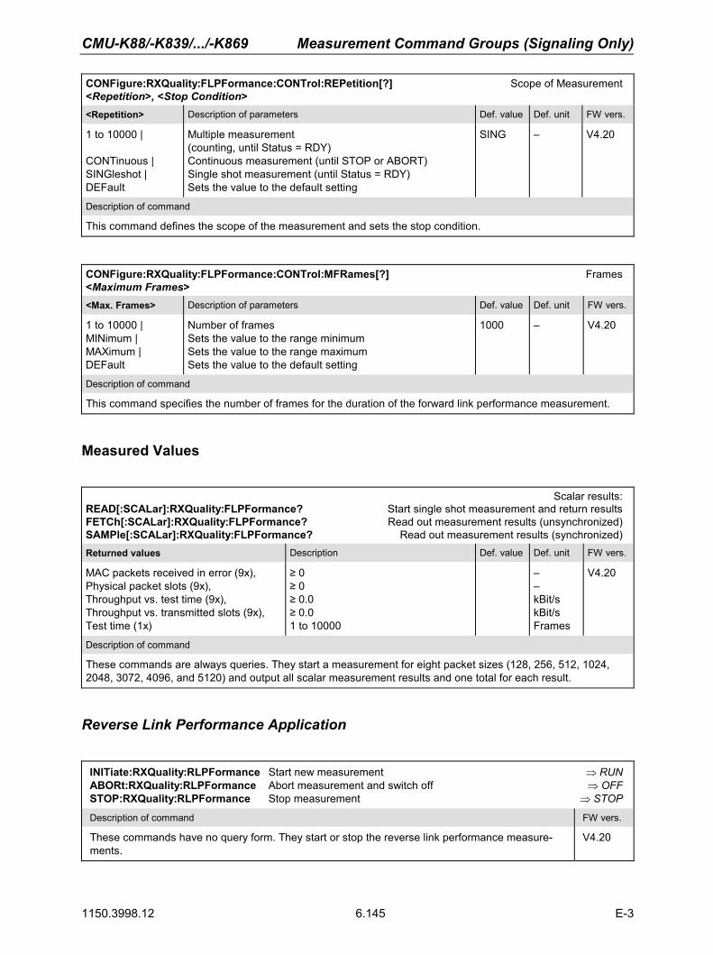
CMU-K88/-K839/.../-K869 Measurement Command Groups (Signaling Only)
1150.3998.12 6.145 E-3
CONFigure:RXQuality:FLPFormance:CONTrol:REPetition[?] Scope of Measurement <Repetition>, <Stop Condition> <Repetition> Description of parameters Def. value Def. unit FW vers.
1 to 10000 | CONTinuous | SINGleshot | DEFault
Multiple measurement (counting, until Status = RDY) Continuous measurement (until STOP or ABORT) Single shot measurement (until Status = RDY) Sets the value to the default setting
SING – V4.20
Description of command
This command defines the scope of the measurement and sets the stop condition.
CONFigure:RXQuality:FLPFormance:CONTrol:MFRames[?] Frames <Maximum Frames><Max. Frames> Description of parameters Def. value Def. unit FW vers.
1 to 10000 | MINimum | MAXimum | DEFault
Number of frames Sets the value to the range minimum Sets the value to the range maximum Sets the value to the default setting
1000 – V4.20
Description of command
This command specifies the number of frames for the duration of the forward link performance measurement.
Measured Values
Scalar results:
READ[:SCALar]:RXQuality:FLPFormance? Start single shot measurement and return results FETCh[:SCALar]:RXQuality:FLPFormance? Read out measurement results (unsynchronized) SAMPle[:SCALar]:RXQuality:FLPFormance? Read out measurement results (synchronized) Returned values Description Def. value Def. unit FW vers.
MAC packets received in error (9x), Physical packet slots (9x), Throughput vs. test time (9x), Throughput vs. transmitted slots (9x), Test time (1x)
≥ 0≥ 0≥ 0.0 ≥ 0.0 1 to 10000
– –kBit/s kBit/s Frames
V4.20
Description of command
These commands are always queries. They start a measurement for eight packet sizes (128, 256, 512, 1024, 2048, 3072, 4096, and 5120) and output all scalar measurement results and one total for each result.
Reverse Link Performance Application
INITiate:RXQuality:RLPFormance Start new measurement ⇒ RUNABORt:RXQuality:RLPFormance Abort measurement and switch off ⇒ OFFSTOP:RXQuality:RLPFormance Stop measurement ⇒ STOP
Description of command FW vers.
These commands have no query form. They start or stop the reverse link performance measure-ments.
V4.20

Measurement Command Groups (Signaling Only) CMU-K88/-K839/.../-K869
1150.3998.12 6.146 E-3
CONFigure:RXQuality:RLPFormance:EREPorting[?] Event Reporting <ReportMode>
<ReportMode> Description of parameters Def. value Def. unit FW vers.
SRQ | SOPC | SRSQ | OFF | DEFault
Service request Single operation complete SRQ and SOPC No reporting Sets the value to the default setting
OFF – V4.20
Description of command
This command defines the events generated when the reverse link performance measurement is terminated or stopped (event reporting, see chapter 5 of CMU 200/300 operating manual).
FETCh[:SCALar]:RXQuality:RLPFormance:STATus? Measurement Status <MeasurementStatus>, <Curr.Step.CycleCount>, <ElapsedStatistics> <Meas.Status> Description of parameters Def. value Def. unit FW vers.
OFF | RUN | STOP | ERR | RDY,
Measurement in the OFF state (*RST or ABORt) Running (after INITiate, CONTinue or READ) Stopped (STOP) OFF (could not be started) Stopped according to repetition mode and stop condition
OFF – V4.20
<Cycle Count> Description of parameters Def. value Def. unit FW vers.
1 to 10000 | NONE,
Counter for current statistics cycle No step mode set
NONE – V4.20
<ElapsedStatistics> Description of parameters Def. value Def. unit FW vers.
1 to 1000 | NONE
Counter for current evaluation period within a cycle Statistic count set to off
NONE – V4.20
Description of command
This command is always a query. It returns the status of the measurement (see chapters 3 and 5).
CONFigure:RXQuality:RLPFormance:CONTrol:REPetition[?] Scope of Measurement <Repetition>, <Stop Condition> <Repetition> Description of parameters Def. value Def. unit FW vers.
1 to 10000 | CONTinuous | SINGleshot | DEFault
Multiple measurement (counting, until Status = RDY) Continuous measurement (until STOP or ABORT) Single shot measurement (until Status = RDY) Sets the value to the default setting
SING – V4.20
Description of command
This command defines the scope of the measurement and sets the stop condition.

CMU-K88/-K839/.../-K869 Measurement Command Groups (Signaling Only)
1150.3998.12 6.147 E-3
CONFigure:RXQuality:RLPFormance:CONTrol:MFRames[?] Frames <Maximum Frames><Max. Frames> Description of parameters Def. value Def. unit FW vers.
1 to 10000 | MINimum | MAXimum | DEFault
Number of frames Sets the value to the range minimum Sets the value to the range maximum Sets the value to the default setting
1000 – V4.20
Description of command
This command specifies the number of frames for the duration of the reverse link performance measurement.
Measured Values
The measurement results for the Reverse Link Performance measurements depend on the used physi-cal layer protocol. To determine which READ/FETCh command applies, the result (DPLProtocol or S2PL) from [SENse]:LAYer:PHYSical:PLPRotocol:STYPe? can be used.
Scalar results: READ[:SCALar]:RXQuality:RLPFormance:DPLProtocol? Start single shot measurement and return results FETCh[:SCALar]:RXQuality:RLPFormance:DPLProtocol? Read out measurement results (unsynchronized) SAMPle[:SCALar]:RXQuality:RLPFormance:DPLProtocol? Read out measurement results (synchronized) Returned values Description Def. value Def. unit FW vers.
MAC packets received in error (6x), MAC packets received in error total (1x),, Throughput vs. test time (6x), Throughput vs. test time total (1x) Test time (1x)
≥ 0≥ 0≥ 0.0 ≥ 0.0 1 to 10000
– –kBit/s kBit/s Frames
V4.31
Description of command
These commands are always queries. They start a measurement for subtype 0 and output all scalar measurement results. They start a subtype 0 measurement for 6 data rates (0, 9.6, 19.2, 38.4, 76.8, and 153.6 kBit/s) and output all scalar measurement results and one total for each result, as well as the test time in frames.
Scalar results: READ[:SCALar]:RXQuality:RLPFormance:S2PL? Start single shot measurement and return results FETCh[:SCALar]:RXQuality:RLPFormance:S2PL? Read out measurement results (unsynchronized) SAMPle[:SCALar]:RXQuality:RLPFormance:S2PL? Read out measurement results (synchronized) Returned values Description Def. value Def. unit FW vers.
MAC packets received in error (13x), MAC packets received in error total (1x),, Throughput vs. test time (13x), Throughput vs. test time total (1x) Test time (1x)
≥ 0≥ 0≥ 0.0 ≥ 0.0 1 to 10000
– –kBit/s kBit/s Frames
V4.31
Description of command
These commands are always queries. They start a measurement for subtype 2 and output all scalar measurement results. They start a subtype 2 measurement for 13 packet sizes (0, 128, 256, 512, 768, 1024, 1536, 2048, 3072, 4096, 6144, 8192, and 12288) and output all scalar measurement results and one total for each result, as well as the test time in frames.

Measurement Command Groups (Signaling Only) CMU-K88/-K839/.../-K869
1150.3998.12 6.148 E-3
Reverse Link PER Application
INITiate:RXQuality:RLPer Start new measurement ⇒ RUNABORt:RXQuality:RLPer Abort measurement and switch off ⇒ OFFSTOP:RXQuality:RLPer Stop measurement ⇒ STOPCONTinue:RXQuality:RLPer Next measurement step (only step mode) ⇒ RUN
Description of command FW vers.
These commands have no query form. They start or stop the reverse link PER measurements. V4.20
CONFigure:RXQuality:RLPer:EREPorting[?] Event Reporting <ReportMode>
<ReportMode> Description of parameters Def. value Def. unit FW vers.
SRQ | SOPC | SRSQ | OFF | DEFault
Service request Single operation complete SRQ and SOPC No reporting Sets the value to the default setting
OFF – V4.20
Description of command
This command defines the events generated when the reverse link PER measurement is terminated or stopped (event reporting, see chapter 5 of CMU 200/300 operating manual).
FETCh[:SCALar]:RXQuality:RLPer:STATus? Measurement Status <MeasurementStatus>, <Curr.Step.CycleCount>, <ElapsedStatistics> <Meas.Status> Description of parameters Def. value Def. unit FW vers.
OFF | RUN | STOP | ERR | RDY,
Measurement in the OFF state (*RST or ABORt) Running (after INITiate, CONTinue or READ) Stopped (STOP) OFF (could not be started) Stopped according to repetition mode and stop condition
OFF – V4.20
<Cycle Count> Description of parameters Def. value Def. unit FW vers.
1 to 10000 | NONE,
Counter for current statistics cycle No step mode set
NONE – V4.20
<ElapsedStatistics> Description of parameters Def. value Def. unit FW vers.
1 to 1000 | NONE
Counter for current evaluation period within a cycle Statistic count set to off
NONE – V4.20
Description of command
This command is always a query. It returns the status of the measurement (see chapters 3 and 5).

CMU-K88/-K839/.../-K869 Measurement Command Groups (Signaling Only)
1150.3998.12 6.149 E-3
CONFigure:RXQuality:RLPer:CONTrol:REPetition[?] Scope of Measurement <Repetition>, <Stop Condition> <Repetition> Description of parameters Def. value Def. unit FW vers.
1 to 10000 | CONTinuous | SINGleshot | DEFault,
Multiple measurement (counting, until Status = RDY) Continuous measurement (until STOP or ABORT) Single shot measurement (until Status = RDY) Sets the value to the default setting
SING – V4.20
<Stop Condition> Description of parameters Def. value Def. unit FW vers.
NONE | CLEX | PLEX | ALEX | DEFault
No stop condition, continue measurement even in case of error Meas. is stopped when confidence level is exceeded Meas. is stopped when Max. PER Limit is exceeded Meas. is stopped when any limit is exceeded Sets the value to the default setting
NONE – V4.20
Description of command
This command defines the scope of the measurement and sets the stop condition.
CONFigure:RXQuality:RLPer:CONTrol:MPReceived[?] Max. Packets Received <Max Packets Received><Max Packets R.> Description of parameters Def. value Def. unit FW vers.
1 to 1000 | MINimum | MAXimum | DEF
Number of packets to be received Sets the value to the range minimum Sets the value to the range maximum Sets the value to the default setting
1000 – V4.20
Description of command
This command specifies the maximum number of packets for the Reverse Link PER receiver quality measure-ment.
CONFigure:RXQuality:RLPer:LIMit:MPER[?] Reverse Link PER Limit <Max PER Limit><Max PER Limit> Description of parameters Def. value Def. unit FW vers.
0 to 100 | ON | OFF | MINimum | MAXimum | DEFault
Maximum PER limit The PER value check is re-enabled (after OFF) PER limit value check is disabled Sets the value to the range minimum Sets the value to the range maximum Sets the value to the default setting
1 % V4.20
Description of command
This command specifies the limit for the measured reverse link PER for the corresponding receiver quality meas-urement.

Measurement Command Groups (Signaling Only) CMU-K88/-K839/.../-K869
1150.3998.12 6.150 E-3
CONFigure:RXQuality:RLPer:LIMit:CLEVel[?] Reverse Link Confidence Level Limit <Confidence Level Limit><Conf. Level> Description of parameters Def. value Def. unit FW vers.
0 to 100 | ON | OFF | MINimum | MAXimum | DEFault
Confidence level limit The confidence level limit check is re-enabled (after OFF) Confidence level limit check is disabled Sets the value to the range minimum Sets the value to the range maximum Sets the value to the default setting
95 % V4.20
Description of command
This command specifies the confidence level limit for the reverse link PER receiver quality measurement.
Measured Values
The measurement results for the Reverse Link PER measurements depend on the used physical layer protocol. To determine which READ/FETCh command applies, the result (DPLProtocol or S2PL) from [SENse]:LAYer:PHYSical:PLPRotocol:STYPe? can be used.
Scalar results: READ[:SCALar]:RXQuality:RLPer:DPLProtocol? Start single shot measurement and return results FETCh[:SCALar]:RXQuality:RLPer:DPLProtocol? Read out measurement results (unsynchronized) SAMPle[:SCALar]:RXQuality:RLPer:DPLProtocol? Read out measurement results (synchronized) Returned values Description Def. value Def. unit FW vers.
MAC packets transmitted (6x + 1 total), Rev. link MAC packet errors (6x + 1 total), Rev. link confidence level (6x + 1 total), Rev. link PER (6x + 1 total), Termination target MAC packet errors (6x + 1 totalx)Termination target Conf. level (6x + 1 total), Termination target PER (6x + 1 total)
1 to 1000 0 to 1000 0 to 100% 0 to 100% 0 to 1000 0 to 100% 0 to 100%
NAN NAN NAN NAN NAN NAN NAN
––%%–%%
V4.31
Description of command
These commands are always queries. They start a measurement and output all scalar measurement results. They start a measurement for 6 data rates (0, 9.6, 19.2, 38.4, 76.8, and 153.6 kBit/s) and output all scalar measurement results and one total for each result.
To determine the correct READ/FETCh/SAMPLe[:SCALar]:RXQuality:RLPer:... command, use the result from [SENse]:LAYer:PHYSical:PLPRotocol:STYPe?, which returns DPLProtocol | S2PL.

CMU-K88/-K839/.../-K869 Measurement Command Groups (Signaling Only)
1150.3998.12 6.151 E-3
CALCulate:RXQuality:RLPer:DPLProtocol:MATChing:LIMit? Limit Matching Returned values Value range Def. value Def. unit FW vers.
Rev. link PER (6x + 1 total), Rev. link PERConfidence Level (6x + 1 total), Termination target PER (6x + 1 total), Termination target PER Confidence Level (6x + 1 total)
For all values NMAU | NMAL | INV | OK
INV
– V4.31
Description of command
This command is always a query. It indicates whether and in which way the (fixed) limits have been exceeded. The following messages may be generated:
NMAU Tolerance value underflow not matching, underflow NMAL Tolerance value exceeded not matching, overflow INV Measurement invalid invalid
OK Tolerance value matched
The measurement is started for 6 data rates (0, 9.6, 19.2, 38.4, 76.8, and 153.6 kBit/s) and it outputs all scalar measurement results and one total for each result.
Scalar results: READ[:SCALar]:RXQuality:RLPer:S2PL? Start single shot measurement and return results FETCh[:SCALar]:RXQuality:RLPer:S2PL? Read out measurement results (unsynchronized) SAMPle[:SCALar]:RXQuality:RLPer:S2PL? Read out measurement results (synchronized) Returned values Description Def. value Def. unit FW vers.
MAC packets transmitted (13x + 1 total), Rev. link MAC packet errors (13x + 1 total), Rev. link confidence level (13x + 1 total), Rev. link PER (13x + 1 total), Termination target MAC packet errors (13x + 1 total) Termination target Conf. level (13x + 1 total), Termination target PER (13x + 1 total)
1 to 1000 0 to 1000 0 to 100% 0 to 100% 0 to 1000 0 to 100% 0 to 100%
NAN NAN NAN NAN NAN NAN NAN
––%%–%%
V4.31
Description of command
These commands are always queries. They start a measurement and output all scalar measurement results. They start a measurement for 13 data rates (0.0, 19.2, 38.4, 76.8, 115.2, 153.6, 230.4, 307.2, 460.8, 614.4, 921.6, 1228.8, and 1843.2 kBit/s) and output all scalar measurement results and one total for each result.
To determine the correct READ/FETCh/SAMPLe[:SCALar]:RXQuality:RLPer:... command, use the result from [SENse]:LAYer:PHYSical:PLPRotocol:STYPe?, which returns DPLProtocol | S2PL.

Measurement Command Groups (Signaling Only) CMU-K88/-K839/.../-K869
1150.3998.12 6.152 E-3
CALCulate:RXQuality:RLPer:S2PL:MATChing:LIMit? Limit Matching Returned values Value range Def. value Def. unit FW vers.
Rev. link PER (13x + 1 total), Rev. link PERConfidence Level (13x + 1 total), Termination target PER (13x + 1 total), Termination target PER Confidence Level (13x + 1 total)
For all values NMAU | NMAL | INV | OK
INV
– V4.30
Description of command
This command is always a query. It indicates whether and in which way the (fixed) limits have been exceeded. The following messages may be generated:
NMAU Tolerance value underflow not matching, underflow NMAL Tolerance value exceeded not matching, overflow INV Measurement invalid invalid
OK Tolerance value matched
The measurement is started for 13 data rates (0.0, 19.2, 38.4, 76.8, 115.2, 153.6, 230.4, 307.2, 460.8, 614.4, 921.6, 1228.8, and 1843.2 kBit/s) and it outputs all scalar measurement results and one total for each result.
Data Applications - RLP Frame / IP Statistics and Ping
The data applications currently comprise the RLP Frame / IP Statistics measurement which determines the data flow on the CMU, and the Ping Measurement, which verifies the availability of a device with a given IP address in the IP-based network. All commands require the R&S CMU-B89 and the R&S CMU-K87 options. Control of Measurement - Common Commands
Here the common commands for all data application measurements are described.
To reset the statics of the RLP Frame / IP Statistics or Ping measurements, send the command: INITiate:LAYer:APPLication:TEST:STATistics (from the Signaling - LAYer subsystem)
Test Configuration – RLP Frame / IP Statistics Application
CONFigure:UPERiod[?] Update Period <Update Period> <Update Rate> Description of parameters Def. value Def. unit FW vers.
0.2 s to 2.0 s | MINimum | MAXimum | DEFault
Update period of the RLP Frame / IP Statistics applicationSets the minimum update period Sets the maximum update period Use default settings
1.0
s V4.30
Description of command Sig. State
This command determines the update period of the RLP Frame / IP Statistics application (absolute value, in seconds).
Note: To reset the statics of the RLP measurement, send the command: INITiate:LAYer:APPLication:TEST:STATistics (from the Sign. - LAYer subsys-tem).
Note: This command replaces the legacy command CONFigure:RXQuality:UPERiod[?], but the old syntax can still be used for compatibility reasons. The command is identical with the one described on p. 6.133.
All

CMU-K88/-K839/.../-K869 Measurement Command Groups (Signaling Only)
1150.3998.12 6.153 E-3
Test Configuration – Ping Application
The subsystem PING controls the Ping measurement. All commands require options R&S CMU-B89 and R&S CMU-K87.
INITiate:PING Start new measurement ⇒ RUN ABORt:PING Abort running measurement and switch off ⇒ OFF STOP:PING Stop measurement after current stat. cycle ⇒ STOP CONTinue:PING Next measurement step (stepping mode) ⇒ RUN Description of command Sig. State FW vers.
These commands have no query form. They start or stop the measurement, setting it to the status given in the top right column.
Please note that the Signaling State is only relevant for AT pings. A server connected to the CMU (via ethernet port) can be pinged in any signaling state.
DORM, CONN
V4.30
CONFigure:PING:EREPorting[?] Event Reporting <Report Mode><Report Mode> Description of parameters Def. value Def. unit FW vers.
SRQ | SOPC | SRSQ | OFF
Service request Single operation complete SRQ and SOPC No reporting
OFF – V4.30
Description of command Sig. State
This command defines the events generated when the measurement is terminated or stopped (event reporting, see chapter 5).
all
FETCh[:SCALar]:PING:STATus? Ping Measurement Status <Stat. Results><Stat. Results> Description of parameters Def. value Def. unit FW vers.
OFF | RUN | STOP | ERR | STEP | RDY, 1 to 10000 | NONE, 1 to 1000 | NONE
Measurement in the OFF state (*RST or ABORt) Running (after INITiate, CONTinue or READ) Stopped (STOP) OFF (could not be started) Stepping mode (<stepmode>=STEP) Stopped according to repetition mode and stop condition Counter for current statistics cycle No counting mode set Counter for current ping within a cycle Statistic count set to off
OFF
NONE
NONE
–
–
–
V4.30
Description of command Sig. State
This command is always a query. It returns the status of the measurement (see chapters 3 and 5) and the statistical results. A statistics cycle comprises the number of pings defined by means of CONFig-ure:PING:CONTrol:PCOunt.
all

Measurement Command Groups (Signaling Only) CMU-K88/-K839/.../-K869
1150.3998.12 6.154 E-3
Subsystem PING:CONTrol
The subsystem PING:CONTrol provides specific settings for the PING measurement. These settings are provided in the Control tab of the popup menu Ping Configuration.
DEFault:PING:CONTrol[?] Default Settings <Enable><Enable> Description of parameters Def. value Def. unit FW vers.
ON | OFF
The parameters are set to their default values The parameters differ from the default values (partially or totally)
ON – V4.30
Description of command Sig. State
If used as a setting command with the parameter ON, this command sets all parameters of the subsys-tems to their default values (the setting OFF results in an error message).
If used as a query the command returns whether all parameters are set to their default values (ON) or not (OFF).
all
CONFigure:PING:CONTrol:REPetition[?] Test Cycles <Repetition>, <Stop Cond>, <Step Mode> <Repetition> Description of parameters Def. value Def. unit FW vers.
1 to 10000 | CONTinuous | SINGleshot | DEFault,
Multiple measurement (counting, until Status = STEP | RDY Continuous measurement (until STOP or ABORT) Single shot measurement (until Status = RDY) Default value
SING – V4.30
<Stop Cond> Description of parameters Def. value Def. unit FW vers.
NONE, Continue measurement even in case of error NONE – V4.30
<Step Mode> Description of parameters Def. value Def. unit FW vers.
NONE Continue measurement according to its rep. mode NONE – V4.30
Description of command Sig. State
This command determines the repetition mode for the ping measurement. Stop condition, and stepping mode are not used and must be set to NONE. Note: In the case of READ commands (READ:...), the <Repetition> parameter has no effect;
the measurement is always stopped after a single shot.
all
CONFigure:PING:CONTrol:PCOunt[?] Ping Count <Pings><Pings> Description of parameters Def. value Def. unit FW vers.
1 to 255 Ping count 5 – V4.30
Description of command Sig. State
This command defines the number of pings in a statistics cycle. all

CMU-K88/-K839/.../-K869 Measurement Command Groups (Signaling Only)
1150.3998.12 6.155 E-3
CONFigure:PING:CONTrol:RINTerval[?] Repeat Interval <Time><Time> Description of parameters Def. value Def. unit FW vers.
1 s to 100 s Repeat interval 1 s V4.30
Description of command Sig. State
This command defines the time between two consecutive echo requests. all
CONFigure:PING:CONTrol:TOUT[?] Timeout <Time><Time> Description of parameters Def. value Def. unit FW vers.
0.001 s to 10 s Ping timeout 0.5 s V4.30
Description of command Sig. State
This command defines the timeout to wait for each reply. all
CONFigure:PING:CONTrol:PSIZe[?] Packet Size <Bytes><Bytes> Description of parameters Def. value Def. unit FW vers.
1 byte to 1520 bytes Packet size 32 bytes V4.30
Description of command Sig. State
This command defines the number of bytes in the send buffer. all
CONFigure:PING:CONTrol:ATIP[?] Use AT IP Address <Enable><Enable> Description of parameters Def. value Def. unit FW vers.
ON | OFF
Use MS IP Address Use address def. via CONFigure:PING:CONTrol:IPADdress
ON – V4.30
Description of command Sig. State
This command qualifies whether the pings are sent to the AT IP address used for establishing the MIP/PPP connection or to a different address reserved for pings.
all
CONFigure:PING:CONTrol:IPADdress[?] IP Address, Ping <Addr_1>, <Addr_2>, <Addr_3>, <Addr_4>
<Address parts> Range of values Def. value Def. unit FW vers.
<Addr_1>, 0 to 255 0 – V4.30
<Addr_2>, 0 to 255 0 –
<Addr_3>, 0 to 255 0 –
<Addr_4> 0 to 255 0 –
Description of command Sig. State
This command defines the IP address used for the ping measurement if CONFigure:PING:CONTrol:ATIP is set to OFF.
all

Measurement Command Groups (Signaling Only) CMU-K88/-K839/.../-K869
1150.3998.12 6.156 E-3
Measured Values – RLP Frame / IP Statistics
The subsystem RLP Frame / IP Statistics determines and outputs the results of the RLP Frame / IP Statistics measurement. [SENSe][:SCALar]:RLPStatistic? RLP Frame / IP Statistics results Returned values: Value range Def. value Def. unit FW vers.
<RLP Reset Msgs Tx/Rx>
ResetMsgs (Rx), ResetMsgs (RxTotal), ResetMsgs (Tx), ResetMsgs (TxTotal),
0 to 2^32 (messages) 0 to 2^32 (messages) 0 to 2^32 (messages) 0 to 2^32 (messages)
NAN, NAN, NAN, NAN
––––
V4.30
<RLP ResetAck Msgs Tx/Rx>
ResetAckMsgs (Rx), ResetAckMsgs (RxTotal), ResetAckMsgs (Tx), ResetAckMsgs (TxTotal),
0 to 2^32 (messages) 0 to 2^32 (messages) 0 to 2^32 (messages) 0 to 2^32 (messages)
NAN, NAN, NAN, NAN
––––
V4.30
<RLP Nak Msgs Tx/Rx>
ResetNakMsgs (Rx), ResetNakMsgs (RxTotal), ResetNakMsgs (Tx), ResetNakMsgs (TxTotal),
0 to 2^32 (messages) 0 to 2^32 (messages) 0 to 2^32 (messages) 0 to 2^32 (messages)
NAN, NAN, NAN, NAN
––––
V4.30
<RLP Msgs Summary Tx/Rx>
Summary (Rx), Summary (RxTotal), Summary (Tx), Summary (TxTotal),
0 to 2^32 (messages) 0 to 2^32 (messages) 0 to 2^32 (messages) 0 to 2^32 (messages)
NAN, NAN, NAN, NAN
––––
V4.30
<Total Rx>
TotalRx_PPPBytes, TotalRx_DataRate,
0 to 2^32 (kBytes) 0 to 3072 (kBit/s)
NAN, NAN
––
V4.30
<Total Tx>
TotalTx_PPPBytes, TotalTx_DataRate
0 to 2^32 (kBytes) 0 to 3072 (kBit/s)
NAN, NAN
––
V4.30
Description of command
This commands is always a query. It returns all current RLP Frame and IP statistics measurement results.

CMU-K88/-K839/.../-K869 Connection Control (Signaling Only)
1150.3998.12 6.157 E-3
Measured Values – Ping
The following commands return the results of the PING measurement.
Ping Results: READ[:SCALar]:PING? Start single shot measurement and return results FETCh[:SCALar]:PING? Read out measurement results (unsynchronized) SAMPle[:SCALar]:PING? Read out measurement results (synchronized) <Results> Description of parameters Def. value Def. unit FW vers.
‘0.0.0.0’ to ‘255.255.255.255’, 1 byte to 1520 bytes, 0.0 s to 10.0 s | NHOS | TOUT | ILNK, …0.0 s to 10.0 s | NHOS | TOUT | ILNK
IP address 1 (16-character string) Packet size 1 Ping time; time to wait for the reply 1 …Time to wait for the reply 5
NAN NAN NAN …NAN
–––…–
V4.30
Description of command Sig. State
These commands are always queries. They start the ping measurement (READ…) and return the re-sults. If a ping count (CONFigure:PING:CONTrol:PCOunt) larger than 5 is set, the last 5 results in the statistics cycle are returned. If the ping timeout (CONFigure:PING:CONTrol:TOUT) is exceeded, one of the following error conditions is returned instead of the ping time:
NHOS No host ILNK Inactive link TOUT Timeout
Please note that the Signaling State is only relevant for AT pings. A server connected to the CMU (via ethernet port) can be pinged in any signaling state.
DORM, CONN
Connection Control (Signaling Only)
The remote-control commands presented in this section control the signaling (call setup and release, services, signaling parameters), determine the inputs and outputs as well as the reference frequency. They correspond to the settings in the popup menu of the softkey Connect Control located at the top right of each main menu.
Note: Some parameters of the CMU can take on several independent values: The default value is used to set up a call; most default values can be modified in the signaling states Signal Off,Signal On and Registered. The current value during the call (signaling states Connected) can still be changed, however, modifying this current value does not alter the default value. The handoff value comes into effect after a handoff from another to the current network; most handoff values can be set in all signaling states.
Note: Many of the default and current parameters in 1xEV-DO occur in the Signaling and in the ANSignal subsystems.
Default values are set with a CONFigure ... command, current values are set with the corresponding PROCedure ... command.

Connection Control (Signaling Only) CMU-K88/-K839/.../-K869
1150.3998.12 6.158 E-3
Subsystem Signaling (Connection Setup and Cleardown)
The subsystem Signaling controls the call setup and cleardown from the CMU to the access terminal and determines the signaling parameters. It corresponds to the tab Connection (for different signaling states, see command PROCedure:SIGNalling:ACTion) in the popup menu Connection Control.
PROCedure:SIGNalling:ACTion Signaling Control <Action>
<Action> Description of parameters Def. value Def. unit FW vers.
SOFF | SON | CSESsion | RNEGotiate | CTMobile | CRELease | HANDoff
Switch off RF signal (Signal Off) Switch on RF signal (Signal On) Close Session Renegotiate Call to mobile (not for CONF:SCON:SCL1:SERV WMT)Call release Handoff (only in signaling state CEST)
SOFF – V4.20
Description of command Sig. State
This command has no query form. It changes between the different signaling states of the CMU. The current state can be queried via SIGN:STAT?
See be-low
SON(Signal ON)
SON
Default
SOFF
SOFF(Signal OFF)
SOP(Session Open)
SignalOff
CEST(Connected)
SignalOff
SignalOff
FPEN(Fallback pending)
CPEN(Connect. pending)
NEG( Negotiation)Session
Fail
ATini
t
Success
RNEGotiate
CTMobileCRELease
SOFF
SO
FF
RNEGotiate
CSESsion
CSESsion
SOFF
Transitory States
HANDoff (with Fallback)
HANDoff
Figure 6-1: Signaling states of the CMU
Signaling states:
See description of command [SENSe:]SIGNalling:STATe?
Actions (initiated from the CMU): See description of command [PROCedure:]SIGNalling:ACTion
Further transitions between the signaling states (not shown in figure 6-1) may occur, e.g. in case of er-rors.

CMU-K88/-K839/.../-K869 Connection Control (Signaling Only)
1150.3998.12 6.159 E-3
[SENSe:]SIGNalling:STATe? Signaling State
Return Description of parameters Def. value Def. unit FW vers.
SOFF | SON | NEG | SOP | CEST | CPEN | FPEN
Signal for synchronization switched off (Signal Off) Signal for synchronization switched on (Signal On) Session Negotiation Session Open Connection Established (Connected)Connection pending Fallback pending
SOFF – V4.20
Description of command Sig. State
This command is always a query. It returns the current signaling state. All
All PPP-related states must be triggered externally, there is no corresponding remote command to set these states.
CONN(PPP Connected)
Default
Close Session
OFF(PPP Off)
DORM(PPP Dormant)
Connect Radio Link
Disconnect Radio Link
Close Sess
ionConne
ctRadio
Link
withPPP
applic
ation
Figure 6-2: PPP Signaling states of the CMU
[SENSe:]SIGNalling:STATe:PPP? PPP Signaling State Returns Description of parameters Def. value Def. unit FW vers.
OFF | DORM | CONN
PPP off PPP dormant PPP connected
OFF – V4.20
Description of command Sig. State
This command is always a query. It returns the current signaling state. All

Connection Control (Signaling Only) CMU-K88/-K839/.../-K869
1150.3998.12 6.160 E-3
Subsystem AT Information
[SENSe]:ATINfo:UATi? UATI <UATI> <UATI> Description of parameter Def. value Def. unit FW vers.
'<17 characters>' UATI (Unicast Access Terminal Identifier), string parameter
'---' – V4.20
Description of command Sig. State
This command is always a query. It returns the Unicast Access Terminal Identifier of the AT. All
[SENSe]:ATINfo:ESN? ESN <ESN> <ESN> Description of parameter Def. value Def. unit FW vers.
'<9 characters>' ESN (Electronic Serial Number), string parameter '---' – V4.20
Description of command Sig. State
This command is always a query. It returns the hardcoded Electronic Serial Number of the AT. All
[SENSe]:ATINfo:MEID? MEID <MEID> <MEID> Description of parameter Def. value Def. unit FW vers.
'<15 characters>' MEID (Mobile Equipment Identifier), string parameter '---' – V4.20
Description of command Sig. State
This command is always a query. It returns the Mobile Equipment Identifier of the AT. All
[SENSe]:ATINfo:PREFerred:CCHannel:CYCLe:ENABle? Preferred Control Ch. Enable <Preferred Control Ch. Enable> <Enable> Description of parameters Def. value Def. unit FW vers.
ON | OFF Preferred control channel is enabled or disabled OFF – V4.31
Description of command Sig. State
This command returns whether or not the AT is providing the AN with the preferred control channel cycle or not. If the value indicates disabled (OFF), that means the AN and AT both use a common hash function to derive the preferred control channel cycle. If the value indicates enabled (ON), the AT determines the preferred control channel cycle and tells the AN to use this value.
All
[SENSe]:ATINfo:PREFerred:CCHannel:CYCLe? Preferred Control Ch. Cycle <Preferred Control Ch. Cycle> <PCCCycle> Description of parameters Def. value Def. unit FW vers.
0 to 32767 Number of preferred control channel cycles 255 – V4.31
Description of command Sig. State
This command is always a query. It returns which preferred control channel cycle is being used by the AT and AN.
All

CMU-K88/-K839/.../-K869 Connection Control (Signaling Only)
1150.3998.12 6.161 E-3
Subsystem Handoff
The subsystem Handoff controls the parameters relevant to the network handoff. It corresponds to the tab Handoff in the popup menu Connection Control.
PROCedure:BC:HANDoff[?] Network Standard / Channel <Target Network BC/CH> Description of parameters Def. value Def. unit FW vers.
<Standard>, <value> CH | HZ | KHZ | MHZ | GHZ
Network Standard (see CONFigure:NETWork:STANdard[?]), RF Channel number or frequency unit
0
CH
–
–
V4.20
Description of command Sig. State
This command is used to set and trigger or to return the band class and RF channel for handoff, e.g. PROC:BC:HAND KCEL, 150 CH. The default values (def, min, max) depend on the target network standard.
Note: The handoff between different networks requires an existing connection between the CMU and AT, i.e. it is only possible in the Connected state (see Figure 6-1) within the same band class.
CEST
Subsystem Layer
The subsystem Layer controls the parameters relevant to the network layers. It corresponds to the tab Layer in the popup menu Connection Control.
DEFault:LAYer[?] Layer Returns Description of parameters Def. value Def. unit FW vers.
OFF | ON
The layer parameters are set to their default values The layer parameters differ from the default values (partially or totally)
ON – V4.20
Description of command Sig. State
If used as a setting command with the parameter ON, this command sets all parameters of the sub-systems LEVel to their default values (the setting OFF results in an error message).
If used as a query the command returns whether all parameters are set to their default values (ON) or not (OFF).
Note: CONFigure:LAYer:UPDate:MODE[?] is not affected by this command.
All

Connection Control (Signaling Only) CMU-K88/-K839/.../-K869
1150.3998.12 6.162 E-3
CONFigure:LAYer:UPDate:MODE[?] Renegotiation after Layer Update Mode <Layer Parameter Update Mode> <Layer Par. Update Mode> Description of parameters Def. value Def. unit FW vers.
IMMediate |
USER |
DEFault
Layer parameter updates are processed immedi-ately, which causes a renegotiation between AT and AN. Layer parameter updates are collected and up-dated when the user triggers the update (see below) Sets the update mode to the default value
IMM – V4.20
Description of command Sig. State
This command determines the Layer Update Mode and it applies to all commands of the LAYer sub-system. By default, every command updates the appropriate parameters IMMediately. However this will cause a new time-consuming renegotiation between AccessTerminal and Access Network for each individual command.
For better performance the user can decide when he wants to trigger a renegotiation by setting this update mode to USER. In this case, all settings which are done in the LAYer subsystem do not take effect until the user triggers a renegotiation by sending PROCedure:SIgnalling:ACTion RNEGotiate.
When the user resets this parameter from USER to IMMediate an automatic renegotiation is trig-gered.
This parameter is not affected by DEFault:RFANalyzer[?].
In order to reset this a SYSTem:RESet:CURRent or *rst is required.
All
Subsystem Default Signaling Application
The Default Signaling Application provides the means to carry messages between a protocol in one entity and the same protocol in the other entity. The Default Signaling Application consists of a messag-ing protocol (Signaling Network Protocol) and a link layer protocol that provides message fragmentation, retransmission and duplicate detection (Signaling Link Protocol).
CONFigure:LAYer:APPLication:DSIGnaling:ENABle? Default Signaling Application Enable <Default Signaling App - Enable> Returns Description of parameters Def. value Def. unit FW vers.
ON | OFF
The application layer default signaling application is enabled The application layer default signaling application is disabled
ON – V4.20
Description of command Sig. State
This command is always a query. It returns the default signaling application status. All
CONFigure:LAYer:APPLication:DSIGnaling:STReam? Default Signaling Application Cfg. <Default Signaling App - Stream no.> Returns Description of parameters Def. value Def. unit FW vers.
0 | 1 The stream number of the default signaling application 0 – V4.20
Description of command Sig. State
This command is always a query. It returns the stream number of the default signaling application. All

CMU-K88/-K839/.../-K869 Connection Control (Signaling Only)
1150.3998.12 6.163 E-3
[Sense]:ATINfo:APPLication:DSIGnaling:Support? Default Signaling Application AT Support<Default Signaling App - AT Support> Returns Description of parameters Def. value Def. unit FW vers.
ON | OFF
The default signaling application is supported The default signaling application is not supported
ON – V4.20
Description of command Sig. State
This command is always a query. It returns the support status of the defaultsignaling application. All
Subsystem Default Test Application
The Default Test Application (or Default Packet Application) consists of a link layer protocol that pro-vides octet retransmission and duplicate detection (Radio Link Protocol), a location update protocol that provides mobility between data service networks and a flow control protocol that provides flow control of data traffic. INITiate:LAYer:APPLication:TEST:STATistics Reset statistics test application Description of command Sig. State FW vers.
This commands has no query form. It resets the connection statistics for the enabled test application, thus all RxQuality measurements are restarted.
Note: This command can be submitted in all signalling states, but useful results will only be obtained in state CEST.
CEST/All (see Note)
V4.20
CONFigure:LAYer:APPLication:TESt:ENABle[?] Test Application Enable<Test App - Enable> <TA Enable> Description of parameters Def. value Def. unit FW vers.
ON | OFF | DEFault
The application layer default test application is enabled The application layer default test application is disabled Sets the test application to the default value
OFF – V4.20
Description of command Sig. State
This command sets or returns the selected test application status. All
CONFigure:LAYer:APPLication:TESt:SELect[?] Test Application Select <Test App - Select> <TA Select> Description of parameters Def. value Def. unit FW vers.
OFF | FORWard | REVerse | FR | DEFault
The application layer test application is disabled Selects the forward link test application Selects the reverse link test application Selects the forward & reverse link test application Sets the test application default value
FORWard – V4.30
Description of command Sig. State
This command sets or returns the selected test application. All

Connection Control (Signaling Only) CMU-K88/-K839/.../-K869
1150.3998.12 6.164 E-3
CONFigure:LAYer:APPLication:TESt:STReam[?] Default Test Application Stream<Default Test App - Stream No.> <Stream No.> Description of parameters Def. value Def. unit FW vers.
1 to 3 | MINimum | MAXimium | DEFault | INValid
The test application stream number Sets the stream number to the minimum setting (0) Sets the stream number to the maximum setting (3) Sets the stream number to the default setting Returns NAN for an invalid or no stream assignment (query only)
1 – V4.20
Description of command Sig. State
This command sets or returns the stream number assigned to the default test application. Per de-fault, stream 0 may only be used for the Default Signalling Application.
All
[SENSe]:ATINfo:APPLication:TEST:SUPPort? Default Test Application AT Support <Default Test App - AT Support> Returns Description of parameters Def. value Def. unit FW vers.
ON | OFF
The AT supports the default test application. The AT supports the configured test application.
ON – V4.20
Description of command Sig. State
This command is always a query. It returns the AT support status of the test application, which is related to the selected FTAP/RTAP parameters used to determine the application performance.
All

CMU-K88/-K839/.../-K869 Connection Control (Signaling Only)
1150.3998.12 6.165 E-3
CONFigure:LAYer:APPLication:DTESt:FTAP:DRC:DRINdex[?] Data Rate Configuration (DRC) <Data Rate Index><Data Rate Index> Description of parameters Def. value Def. unit FW vers.
0 to 12 | MINimum | MAXimum | OFF | ON | DEFault
Data rate index Sets the data rate index to 0 Sets the data rate index to 12 With the data rate index set to OFF, the mobile deter-mines the DRC rate based on internal algorithms. With the data rate index set to ON, the mobile uses the last stored value of the data rate index Sets the value to the default setting
1 – V4.20
Description of command Sig. State
This command sets the data rate index for the control channel sync. message. The data rate index defines an unambiguous assignment of the data rate and the slot count, as shown below:
Index Rate [kBit/s] #Slots 0 0.0 n/a 1 38.4 16 2 76.8 8 3 153.6 4 4 307.2 2 5 307.2 4 6 614.4 1 7 614.4 2 8 921.6 2 9 1228.8 1
10 1228.8 2 11 1843.2 1 12 2457.6 1
Please note that a data rate index of "0" stops all FTAP packets going to the mobile.
The data rate can be queried with the command CONFigure:LAYer:APPLication:DTESt:FTAP:DRC:DRATe? The slot count can be queried using CONFigure:LAYer:APPLication:DTESt:FTAP:DRC:SCOunt?
All
CONFigure:LAYer:APPLication:DTESt:FTAP:DRC:DRATe? DRC Rate <Data Rate><Data Rate> Description of parameters Def. value Def. unit FW vers.
0.0 to 2457.6 Data rate 38.4 kBit/s V4.20
Description of command Sig. State
This command is always a query. It returns the data rate assigned to the data rate index that can be set with the command CONFigure:LAYer:APPLication:DTESt:FTAP:DRC:DRINdex
All

Connection Control (Signaling Only) CMU-K88/-K839/.../-K869
1150.3998.12 6.166 E-3
CONFigure:LAYer:APPLication:DTESt:FTAP:DRC:SCOunt? DRC Slot Count <Slot Count><Slot Count> Description of parameters Def. value Def. unit FW vers.
0 to 16 Slot count 16 – V4.20
Description of command Sig. State
This command is always a query. It returns the slot count assigned to the data rate index that can be set with the command CONFigure:LAYer:APPLication:DTESt:FTAP:DRC:DRINdex
All
CONFigure:LAYer:APPLication:DTESt:FTAP:LBACk:ENABle? Loopback Enable Status <Loopback Enable> <Loopback> Description of parameters Def. value Def. unit FW vers.
ON | OFF | DEFault
The FTAP loopback is enabled The FTAP loopback is disabled Sets the FTAP loopback to the default value
ON – V4.20
Description of command Sig. State
This command is always a query. It returns the status of the Loopback parameter. If the FTAP loop-back is enabled, the AT sends a record for every packet that it successfully decodes. From this, the CMU calculates the percentage of faulty packets.
The status of the Loopback parameter depends on the FTAP/RTAP configuration (only FTAP -> Loopback is ON, only RTAP -> Loopback is OFF, both FTAP and RTAP -> Loopback is OFF).
All
CONFigure:LAYer:APPLication:DTESt:FTAP:ACK:FMODe[?] ACK Channel Fix Mode <ACK Channel Fix Mode> <Ch. Mode> Description of parameters Def. value Def. unit FW vers.
NUSed | AALWays | NAALways
The AT decides when to ACK or NAK the packets ACK Always NAK Always
NAAL – V4.20
Description of command Sig. State
This command controls the ACK channel in the reverse signal. The ACK channel is used by the AT to inform the AN whether or not the physical layer packet transmitted on the Forward Traffic Channel has been received successfully.
All

CMU-K88/-K839/.../-K869 Connection Control (Signaling Only)
1150.3998.12 6.167 E-3
CONFigure:LAYer:APPLication:DTESt:RTAP:DATa:RMIN:INDex[?] Data Min. Rate <RTAP Min. Data Rate Index><Data Rate Index> Description of parameters Def. value Def. unit FW vers.
0 to 5 | MINimum | MAXimum | DEFault
RTAP minimum data rate index Sets the data rate index to 0 Sets the data rate index to 5 Sets the value to the default setting
1 – V4.20
Description of command Sig. State
This command sets the minimum data rate index for the reverse channel test application protocol. The data rate index defines an unambiguous assignment of the data rate, as shown for CONFigure:LAYer:APPLication:DTESt:FTAP:DRC:DRINdex[?].
If the entered value is greater than the setting of CONFigure:LAYer:APPLication:DTESt:RTAP:DATA:RMAX:INDex[?] then the CONFigure:LAYer:APPLication:DTESt:RTAP:DATA:RMAX:INDex[?] will be adapted to the entered value.
The data rates for RTAP are:
Data Rate Index Data Rate (kBit/s)
0 0.0
1 9.6
2 19.2
3 38.4
4 76.8
5 153.6
The data rate can be queried with the command CONFigure:LAYer:APPLication:DTESt:RTAP:DATa:RMIN:VALue?
All
CONFigure:LAYer:APPLication:DTESt:RTAP:DATa:RMAX:INDex[?] Data Max. Rate <RTAP Max. Data Rate Index><Data Rate Index> Description of parameters Def. value Def. unit FW vers.
1 to 5 | MINimum | MAXimum | DEFault
RTAP maximum data rate index Sets the data rate index to 1 Sets the data rate index to 5 Sets the value to the default setting
1 – V4.20
Description of command Sig. State
This command sets the maximum data rate index for the reverse channel test application protocol. The data rate index defines an unambiguous assignment of the data rate, as shown for CONFigure:LAYer:APPLication:DTESt:FTAP:DRC:DRINdex[?].
If the entered value is less than the setting of CONFigure:LAYer:APPLication:DTESt:RTAP:DATA:RMIN:INDex[?] then the CONFigure:LAYer:APPLication:DTESt:RTAP:DATA:RMIN:INDex[?] will be adapted to the entered value.
The data rate can be queried with the command CONFigure:LAYer:APPLication:DTESt:RTAP:DATa:RMAX:VALue?
All

Connection Control (Signaling Only) CMU-K88/-K839/.../-K869
1150.3998.12 6.168 E-4
CONFigure:LAYer:APPLication:DTESt:RTAP:DATA:RMIN:VALue? Data - Min. Rate <RTAP Min Data Rate>Returns Description of parameters Def. value Def. unit FW vers.
0.0 to 153.6 Data rate 9.6 kBit/s V4.20
Description of command Sig. State
This command is always a query. It returns the data rate assigned to the RTAP min. data rate index that can be set with the command CONFigure:LAYer:APPLication:DTESt:RTAP:DATa:RMIN:INDex
All
CONFigure:LAYer:APPLication:DTESt:RTAP:DATA:RMAX:VALue? Data - Max. Rate <RTAP Max. Data Rate>Returns Description of parameters Def. value Def. unit FW vers.
0.0 to 153.6 Data rate 9.6 kBit/s V4.20
Description of command Sig. State
This command is always a query. It returns the data rate assigned to the RTAP max. data rate index that can be set with the command CONFigure:LAYer:APPLication:DTESt:RTAP:DATa:RMAX:INDex
All
Subsystem Enhanced Test Application
The functionality of the Enhanced Test Application is similar to the Default Test Application except that the enhanced application provides support for different data rates and enhanced statistics. The En-hanced Test Application is only available for Network Release A (see also chapter 4, section Network Parameters (Connection Control – Network)). CONFigure:LAYer:APPLication:ETESt:FETap:DRC:PTINdex[?] Packet Type Index <Packet Type Index><Packet Type Index>
Description of parameters Def. Value Def. unit FW vers.
0 to 37 | MINimum | MAXimum | OFF | ON | DEFault
Data rate index Sets the data rate index to 0 Sets the data rate index to 37 With the packet type index set to OFF, the mobile deter-mines the packet type rate based on internal algorithms. With the packet type index set to ON, the mobile uses the last stored value of the packet type index Sets the value to the default setting
1 V5.00
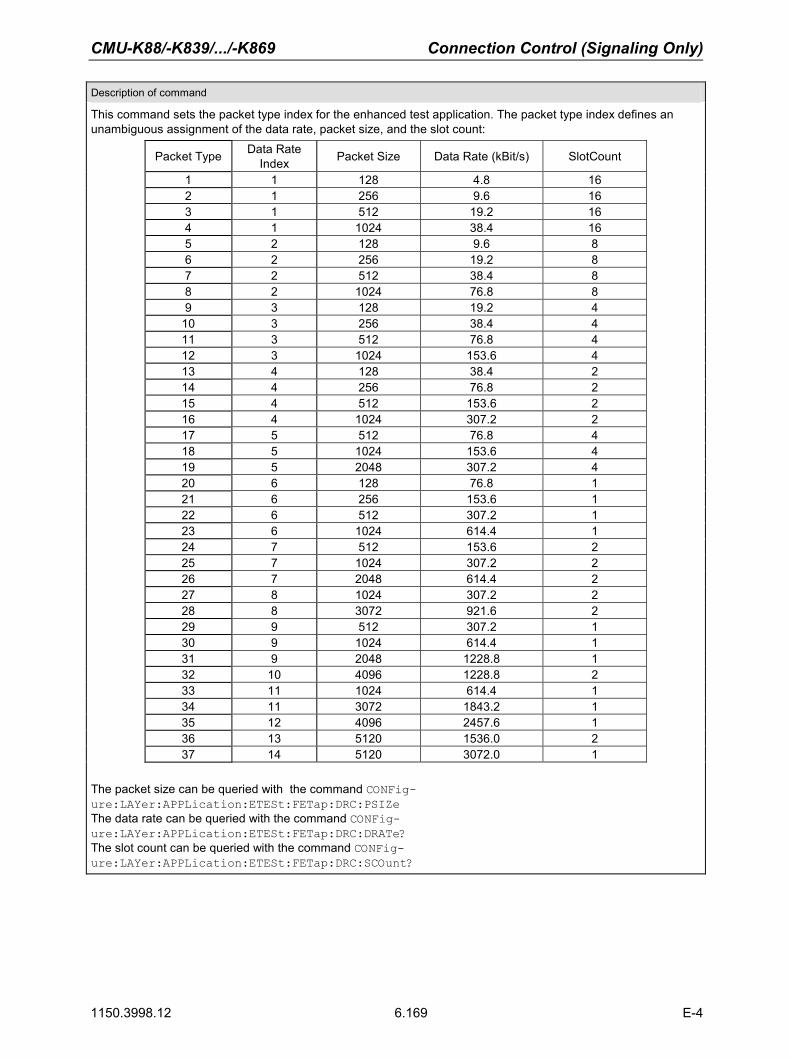
CMU-K88/-K839/.../-K869 Connection Control (Signaling Only)
1150.3998.12 6.169 E-4
Description of command
This command sets the packet type index for the enhanced test application. The packet type index defines an unambiguous assignment of the data rate, packet size, and the slot count:
Packet Type Data Rate Index Packet Size Data Rate (kBit/s) SlotCount
1 1 128 4.8 16 2 1 256 9.6 16 3 1 512 19.2 16 4 1 1024 38.4 16 5 2 128 9.6 8 6 2 256 19.2 8 7 2 512 38.4 8 8 2 1024 76.8 8 9 3 128 19.2 4
10 3 256 38.4 4 11 3 512 76.8 4 12 3 1024 153.6 4 13 4 128 38.4 2 14 4 256 76.8 2 15 4 512 153.6 2 16 4 1024 307.2 2 17 5 512 76.8 4 18 5 1024 153.6 4 19 5 2048 307.2 4 20 6 128 76.8 1 21 6 256 153.6 1 22 6 512 307.2 1 23 6 1024 614.4 1 24 7 512 153.6 2 25 7 1024 307.2 2 26 7 2048 614.4 2 27 8 1024 307.2 2 28 8 3072 921.6 2 29 9 512 307.2 1 30 9 1024 614.4 1 31 9 2048 1228.8 1 32 10 4096 1228.8 2 33 11 1024 614.4 1 34 11 3072 1843.2 1 35 12 4096 2457.6 1 36 13 5120 1536.0 2 37 14 5120 3072.0 1
The packet size can be queried with the command CONFig-ure:LAYer:APPLication:ETESt:FETap:DRC:PSIZe The data rate can be queried with the command CONFig-ure:LAYer:APPLication:ETESt:FETap:DRC:DRATe? The slot count can be queried with the command CONFig-ure:LAYer:APPLication:ETESt:FETap:DRC:SCOunt?

Connection Control (Signaling Only) CMU-K88/-K839/.../-K869
1150.3998.12 6.170 E-4
CONFigure:LAYer:APPLication:ETESt:FETap:DRC:PSIZe? FETAP DRC Packet Size <Data Rate><FETAP Data Rate> Description of parameters Def. value Def. unit FW vers.
128 to 5120 FETAP Data rate – bit V5.00
Description of command Sig. State
This command is always a query. It returns the packet size assigned to the FETAP packet size index that can be set with the command CONFigure:LAYer:APPLication:ETESt:FETAP:DRC :PTINdex.
All
CONFigure:LAYer:APPLication:ETESt:FETap:DRC:DRATe? FETAP DRC Rate <Data Rate><FETAP Data Rate> Description of parameters Def. value Def. unit FW vers.
38.4 to 3072.0 FETAP Data rate 38.4 kBit/s V4.30
Description of command Sig. State
This command is always a query. It returns the data rate assigned to the FETAP packet size index that can be set with the command CONFigure:LAYer:APPLication:ETESt:FETAP:DRC:PTINdex.
All
CONFigure:LAYer:APPLication:ETESt:FETap:DRC:SCOunt? FETAP DRC Slot Count <FETAP Slot Count><FETAP Slot Count> Description of parameters Def. value Def. unit FW vers.
0 to 16 Slot count 16 – V4.30
Description of command Sig. State
This command is always a query. It returns the slot count assigned to the packet size index that can be set with the command CONFigure:LAYer:APPLication:ETESt:FETAP:DRC :PTINdex.
All
CONFigure:LAYer:APPLication:ETESt:FETap:LBACk:ENABle? FETAP Loopback Enable Status <Loopback Enable> <Loopback> Description of parameters Def. value Def. unit FW vers.
ON | OFF | DEFault
The FETAP loopback is enabled The FETAP loopback is disabled Sets the FETAP loopback to the default value
ON – V4.31
Description of command Sig. State
This command is always a query. It returns the status of the FETAP Loopback parameter. If the FETAP loopback is enabled, the bits sent to the access terminal are looped back to the CMU. The CMU compares the bits received with those sent and can thus calculate the percentage of faulty bits.
The status of the FETAP Loopback parameter depends on the FETAP/RETAP configuration (only FETAP -> Loopback is ON, only RETAP -> Loopback is OFF, both FETAP and RETAP -> Loopback is OFF).
All
CONFigure:LAYer:APPLication:ETESt:FETap:ACK:FMODe[?] FETAP ACK Channel Fix Mode <ACK Channel Fix Mode> <Ch. Mode> Description of parameters Def. value Def. unit FW vers.
NUSed | AALWays | NAALways
A value of NUSed means that the AT decides when to ACK or NAK the packets. It is no longer predetermined by the AN.ACK always NAK always
NUSed – V4.31
Description of command Sig. State
This command controls the ACK channel in the reverse signal. The ACK channel is used by the AT to inform the AN whether or not the physical layer packet transmitted on the Forward Enhanced Traffic Channel has been received successfully.
All

CMU-K88/-K839/.../-K869 Connection Control (Signaling Only)
1150.3998.12 6.171 E-3
CONFigure:LAYer:APPLication:ETESt:FETap: ACK:MTYPe? ACK Channel Modulation Type <ACK Channel Modulation Type> <ACK Ch. Mod. Type> Description of parameters Def. value Def. unit FW vers.
BPSK | OOK | OFF | ON | DEFault
BPSK modulation (for single-user packets) On-Off Keying modulation (for multi-user packets) The channel modulation type is not decided by the CMU, it is determined by the AT. The command is reactivated at the last used setting.Sets default ACK channel modulation
BPSK – V4.31
Description of command
This command sets or returns the current ACK channel modulation type for FETAP testing purposes.
For technical reasons, the setting currently defaults to OFF and the command is restricted to be query only.
CONFigure:LAYer:APPLication:ETESt:RETap:DATa:RMIN:INDex[?] RETAP Data Min. Rate <RETAP Min. Packet Size Index><Packet Size Index> Description of parameters Def. value Def. unit FW vers.
0 to 121) | MINimum | MAXimum | DEFault
RETAP minimum packet size index Sets the packet size index to 0 Sets the packet size index to 121) Sets the value to the default setting
1 – V4.30
Description of command Sig. State
This command sets the minimum data rate index for the reverse channel test application protocol. The data rate index defines an unambiguous assignment of the payload sizes, as shown for CONFigure:LAYer:APPLication:ETESt:FETap:DRC:DRINdex[?].
If the entered value is greater than the setting of CONFigure:LAYer:APPLication:ETESt:RETap:DATA:RMAX:INDex[?] then the CONFigure:LAYer:APPLication:ETESt:RETap:DATA:RMAX:INDex[?] will be adapted to the entered value.
The data rate can be queried with the command CONFigure:LAYer:APPLication:ETESt:RETap:DATa:RMIN:VALue? Note: If the entered value is greater than the setting defined with
CONFigure:LAYer:APPLication:ETESt:RETap:DATA:RMAX:INDex[?] then CONFigure:LAYer:APPLication:DETESt:RETap:DATA:RMAX:INDex[?] will be adapted to the entered value
1) 12 is the absolute maximum. The current max. is restricted to the setting of: CONFigure:LAYer:APPLication:ETESt:RETap:DATA:RMAX:INDex[?]
All

Connection Control (Signaling Only) CMU-K88/-K839/.../-K869
1150.3998.12 6.172 E-3
CONFigure:LAYer:APPLication:ETESt:RETap:DATa:RMAX:INDex[?] RETAP Data Max. Rate <RETAP Max. Data Rate Index><Data Rate Index> Description of parameters Def. value Def. unit FW vers.
1 to 12 | MINimum | MAXimum | DEFault
RETAP maximum data rate index Sets the data rate index to 1 Sets the data rate index to 12 Sets the value to the default setting
1 – V4.31
Description of command Sig. State
This command sets the maximum data rate index for the reverse enhanced channel test application protocol. The data rate index defines an unambiguous assignment of the data rate, as shown for CONFigure:LAYer:APPLication:ETESt:FETap:DRC:DRINdex[?].
If the entered value is less than the setting of CONFigure:LAYer:APPLication:ETESt:RETap:DATA:RMIN:INDex[?] then the CONFigure:LAYer:APPLication:ETESt:RETap:DATA:RMIN:INDex[?] will be adapted to the entered value.
The data rate can be queried with the command CONFigure:LAYer:APPLication:ETESt:RETap:DATa:RMAX:VALue?
All
CONFigure:LAYer:APPLication:ETESt:RETap:ACHannel:RMODe[?] Enhanced Channel Rate Mode <Rate Mode> <Rate Mode> Description of parameters Def. value Def. unit FW vers.
R9K | R19K | R38K | DEFault
The default access channel data rate is 9600 bps The default access channel data rate is 19200 bps The default access channel data rate is 38400 bps Sets the default access channel data rate to default
R9K – V4.31
Description of command Sig. State
This command sets or returns the access channel data rate. All
Subsystem Default Packet Application
The Default Packet Application consists of the link layer protocol that provides octet retransmission and duplicate detection (Radio Link Protocol), the location update protocol that provides mobility between data service networks and the flow control protocol that provides flow control of data traffic. CONFigure:LAYer:APPLication:DPACket:ENABle[?] Default Packet Application Enable <Default Packet App - Enable> <DPA Enable> Description of parameters Def. value Def. unit FW vers.
ON | OFF
The application layer default packet application is enabled The application layer default packet application is disabled
OFF – V4.20
Description of command Sig. State
This command sets or returns the default packet application status. All

CMU-K88/-K839/.../-K869 Connection Control (Signaling Only)
1150.3998.12 6.173 E-3
CONFigure:LAYer:APPLication:DPACket:STReam[?] Default Packet Application Stream <Default Packet App - Stream No.> <Stream No.> Description of parameters Def. value Def. unit FW vers.
1 to 3 | MINimum | MAXimium | DEFault | INValid
The default packet application stream number Sets the stream number to the minimum setting (1) Sets the stream number to the maximum setting (3) Sets the stream number to the default setting Return code for an invalid or no stream assignment (query only)
INV – V4.20
Description of command Sig. State
This command sets or returns the stream number of the default packet application. Stream 0 is re-served for the Default Signaling Application.
All
[SENSe]:ATINfo:APPLication:DPACket:SUPPort? Default Packet Application AT Support <Default Packet App - AT Support> Returns Description of parameters Def. value Def. unit FW vers.
ON | OFF
The default packet application is supported. The default packet application is not supported.
ON – V4.20
Description of command Sig. State
This command is always a query. It returns the AT support status of the default packet application. All
CONFigure:LAYer:APPLication:DPACket:MIP:SAMode[?] Mobile IP Stand Alone Mode <Enable> <Enable> Description of parameters Def. value Def. unit FW vers.
ON | OFF
Mobile IP stand alone mode Mobile IP gateway mode
ON – V4.21
Description of command Sig. State
This command sets or returns the MIP mode that the CMU is configured for. All1
1 This command cannot be used while a packet data connection is active.

Connection Control (Signaling Only) CMU-K88/-K839/.../-K869
1150.3998.12 6.174 E-3
CONFigure:LAYer:APPLication:DPACket:MIP:MHIP[?] Mobile Node Home IP Address <Addr_1>, <Addr_2>, <Addr_3>, <Addr_4> Address parts Ranges of values Def. value Def. unit FW vers. <Addr_1>, 0 to 255 10 – V4.21 <Addr_2>, 0 to 255 10 – <Addr_3>, 0 to 255 10 – <Addr_4> 0 to 255 10 – Description of command Sig. State
This command defines the IP address of the mobile in its home network. All2
CONFigure:LAYer:APPLication:DPACket:MIP:FAIP[?] Foreign Agent Home IP Address <Addr_1>, <Addr_2>, <Addr_3>, <Addr_4> <Address parts> Ranges of values Def. value Def. unit FW vers. <Addr_1>, 0 to 255 NAN – V4.21 <Addr_2>, 0 to 255 NAN – <Addr_3>, 0 to 255 NAN – <Addr_4> 0 to 255 NAN – Description of command Sig. State
This command defines the IP address of the of the Foreign Agent. The command is only available in MIP gateway mode (CONFigure:LAYer:APPLication:DPACket:MIP:SAMode OFF).
All3
CONFigure:LAYer:APPLication:DPACket:MIP:HASecret[?] AT Node Home Agent Secret <Secret> <Secret> Description of parameters Def. value Def. unit FW vers.
‘<max 20 characters>’ 0 to 255 ‘cmu’ – V4.21
Description of command Sig. State
This command defines the secret used by the R&S CMU to do Mobile IP MD5 authentication in MIP stand-alone mode.
All4
CONFigure:LAYer:APPLication:DPACket:MIP:HAIP? AT Node Home Agent IP Address <Addr_1>, <Addr_2>, <Addr_3>, <Addr_4> <Address parts> Ranges of values Def. value Def. unit FW vers. <Addr_1>, 0 to 255 NAN – V4.21 <Addr_2>, 0 to 255 NAN – <Addr_3>, 0 to 255 NAN – <Addr_4> 0 to 255 NAN – Description of command Sig. State
This commands queries the IP address of the Home Agent. This address is programmed in the mo-bile and used for registration and tunneling purposes. It is captured and displayed when a mobile IP call is made.
All
2 This command cannot be used while a packet data connection is active. 3 This command cannot be used while a packet data connection is active and while the CMU is configured for MIP gateway mode (CONFig-ure:LAYer:APPLication:DPACket:MIP:SAMode OFF).
4 This command cannot be used while a packet data connection is active and while the CMU is configured for MIP stand-alone mode (CONFig-ure:LAYer:APPLication:DPACket:MIP:SAMode ON.

CMU-K88/-K839/.../-K869 Connection Control (Signaling Only)
1150.3998.12 6.175 E-3
CONFigure:LAYer:APPLication:DPACket:MIP:COADdress? Care of Address <Addr_1>, <Addr_2>, <Addr_3>, <Addr_4> <Address parts> Ranges of values Def. value Def. unit FW vers.
<Addr_1>, 0 to 255 NAN – V4.21 <Addr_2>, 0 to 255 NAN – <Addr_3>, 0 to 255 NAN – <Addr_4> 0 to 255 NAN – Description of command Sig. State
This commands queries the IP address that the Foreign Agent uses to decapsulate packets which have been tunneled by the home agent and to deliver them to the mobile node. The address is cap-tured and displayed when a mobile IP call is made.
All
CONFigure:LAYer:APPLication:DPACket:MIP:AADV[?] MIP Agent Advertisements <Enable><Enable> Description of parameters Def. value Def. unit FW vers.
ON | OFF Enable or disable advertisements ON – V4.21
Description of command Sig. State
This command enables or disables the R&S CMU to broadcast MIP Agent Advertisements to adver-tise its presence on the network. The command is only available in MIP stand alone mode (CONFig-ure:LAYer:APPLication:DPACket:MIP:SAMode OFF).
All

Connection Control (Signaling Only) CMU-K88/-K839/.../-K869
1150.3998.12 6.176 E-3
CONFigure:LAYer:APPLication:DPACket:MIP:RRCode[?] Registration Reply Code <Code No><Code No> Description of parameters Def. value Def. unit FW vers.
0 |1 |64 | 65 | 66 | 67 | 68 | 69 | 70 | 71 | 72 | 73 | 80 | 81 | 82 | 88 | 128 | 129 | 130 | 131 | 132 | 133 | 134 | 135 | 136
Registration accepted Registration accepted, no simultaneous bindings Reason unspecified Administratively prohibited Insufficient resources MS node failed authentication Home agent failed authentication Requested lifetime too long Poorly formed request Poorly formed reply Requested encapsulation unavailable Van Jacobson compression unavailable Home network unreachable (ICMP error) Home agent host unreachable (ICMP error) Home agent port unreachable (ICMP error) Home agent unreachable (ICMP error) Reason unspecified Administratively prohibited Insufficient resources AT node failed authentication Foreign agent failed authentication Reg. identification mismatch Poorly formed request Too many simultaneous mobility bindings Unknown home agent address
0 – V4.21
Description of command Sig. State
This command defines a code number sent to the mobile in the CAUSE_CODE field of the Registra-tion Reply message. Any number different from the values listed above will be automatically cor-rected. The command is only available in MIP stand-alone mode (CONFig-ure:LAYer:APPLication:DPACket:MIP:SAMode ON).
All
CONFigure:LAYer:APPLication:DPACket:MIP:RRLTime[?] Registration Reply Lifetime <Time><Time> Description of parameters Def. value Def. unit FW vers.
0 s to 65535 s Time remaining before the Access Terminal has to re-register
600 s V4.21
Description of command Sig. State
This command defines the number of seconds remaining before the registration is considered ex-pired. The command is only available in MIP stand-alone mode (CONFig-ure:LAYer:APPLication:DPACket:MIP:SAMode ON). A value of 0 s means that the mobile has to de-register; a value of 65535 s means infinity.
All

CMU-K88/-K839/.../-K869 Connection Control (Signaling Only)
1150.3998.12 6.177 E-3
CONFigure:LAYer:APPLication:DPACket:MIP:AUTHentic:TYPe[?] MIP Authentication Type <Type><Type> Description of parameters Def. value Def. unit FW vers.
R02 | R02B Authentication according to RFC 2002 or RFC 2002bis
R02 – V4.21
Description of command Sig. State
This command selects the authentication protocol for Mobile IP connections. The command is only available in MIP stand alone mode (CONFigure:LAYer:APPLication:DPACket:MIP:SAMode ON).
All
CONFigure:LAYer:APPLication:DPACket:REVerse[:STATic]:IPADdress[?] AT PPP IP Address, Static CONFigure:LAYer:APPLication:DPACket:FORWard[:STATic]:IPADdress[?] AN PPP IP Address, Static
<Addr_1>, <Addr_2>, <Addr_3>, <Addr_4> Address parts Ranges of values Def. value Def. unit FW vers.
<Addr_1> | MIN | MAX | DEF, 0 to 255 192 – V4.20
<Addr_2> | MIN | MAX | DEF, 0 to 255 168 –
<Addr_3> | MIN | MAX | DEF, 0 to 255 1 –
<Addr_4> | MIN | MAX | DEF 0 to 255 1 (for reverse address, AT) 2 (for forward address, AN)
––
Description of command Sig. State
These commands define the static PPP IP addresses of the AT (:REVerse) and the AN/CMU (:FORWard). The addresses are used if the CMU is configured for static IP addressing (CONFig-ure:IPADdress:MODE STATic).
All (ex-cept CEST or DORM)
CONFigure:LAYer:APPLication:DPACket:DNS[:STATic]:IPADdress[?] DNS IP Address, Static <Addr_1>, <Addr_2>, <Addr_3>, <Addr_4> Address parts Ranges of values Def. value Def. unit FW vers.
<Addr_1>, 0 to 255 192 – V4.20
<Addr_2>, 0 to 255 168 –
<Addr_3>, 0 to 255 1 –
<Addr_4> 0 to 255 3 –
Description of command Sig. State
This command defines the static IP address of the DNS used for the packet testing applications with PPP.
All (ex-cept CEST or DORM)

Connection Control (Signaling Only) CMU-K88/-K839/.../-K869
1150.3998.12 6.178 E-3
CONFigure:LAYer:APPLication:DPACket:REVerse:DYNamic:IPADdress? AT PPP IP Address, Dynamic CONFigure:LAYer:APPLication:DPACket:FORWard:DYNamic:IPADdress? AN PPP IP Address, Dynamic <Addr_1>, <Addr_2>, <Addr_3>, <Addr_4> Address parts Ranges of values Def. value Def. unit FW vers.
<Addr_1>, 0 to 255 NAN – V4.20
<Addr_2>, 0 to 255 NAN –
<Addr_3>, 0 to 255 NAN –
<Addr_4> 0 to 255 NAN (for reverse address) NAN (for forward address)
––
Description of command Sig. State
These commands query the dynamically allocated PPP IP addresses of the AT (:REVerse) and the AT/CMU (:FORWard). The addresses are available if the CMU is configured for dynamic IP address-ing using DHCP (CONFigure:IPADdress:MODE DYNamic)
All (ex-cept CEST or DORM)
CONFigure:LAYer:APPLication:DPACket:DNS:DYNamic:IPADdress? DNS IP Address, Dynamic <Addr_1>, <Addr_2>, <Addr_3>, <Addr_4> Address parts Ranges of values Def. value Def. unit FW vers.
<Addr_1>, 0 to 255 NAN – V4.20
<Addr_2>, 0 to 255 NAN –
<Addr_3>, 0 to 255 NAN –
<Addr_4> 0 to 255 NAN –
Description of command Sig. State
This command queries the dynamic IP address of the DNS used for the packet testing applications with PPP.
All (ex-cept CEST or DORM)
CONFigure:LAYer:APPLication:DPACket:AUTHentic:TYPe[?] PPP Authentication Type <Authentication Type> <Auth. Type> Description of parameters Def. value Def. unit FW vers.
NONE | CHAP | PAP
PPP authentication is disabled Challenge-Handshake Authentication Protocol enabled Password Authentication Protocol enabled
NONE – V4.20
Description of command Sig. State
This command selects the authentication protocol for IP connections. If PPP authentication is set to a value different than NONE, Simple IP is used.
All (except CEST or DORM)

CMU-K88/-K839/.../-K869 Connection Control (Signaling Only)
1150.3998.12 6.179 E-3
CONFigure:LAYer:APPLication:DPACket:AUTHentic:UNAMe[?] User name (PPP Authentication) <Username> <Name> Description of parameters Def. value Def. unit FW vers.
'<max. 72 characters>' User name, string parameter
'*' – V4.20
Description of command Sig. State
This command selects the user name for PAP authentication (CONFigure:LAYer :APPLication:DPACket:AUTHentic:TYPe). This command may only be modified while no packet data call is active.
All (except CEST or DORM)
CONFigure:LAYer:APPLication:DPACket:AUTHentic:PWORd[?] Password (PPP Authentication)<Password> <Password> Description of parameters Def. value Def. unit FW vers.
'<max. 72 characters>' Password, string parameter
'*' – V4.20
Description of command Sig. State
This command selects the password for PAP authentication (CONFigure:LAYer :APPLication:DPACket:AUTHentic:TYPe). This command may only be modified while no packet data call is active.
All (except CEST or DORM)
CONFigure:LAYer:APPLication:DPACket:IAControl:NIATimer[?] Network PPP Inactivity Timer<Network PPP Inactivity Timer> <Time> Description of parameters Def. value Def. unit FW vers.
5 s to 60 s | MINimum | MAXimum | DEFault | ON | OFF
Network PPP inactivity timer Sets the Network PPP inactivity timer to the minimum value Sets the Network PPP inactivity timer to the maximum valueSets the Network PPP inactivity timer to the default value Enables the Network PPP inactivity timer No timer used, AT remains in the PPP Connected state
OFF s V4.20
Description of command Sig. State
This command defines the time interval after which the CMU will transition the AT from PPP Con-nected to PPP DORMant state if there is no data being sent to the AT. The timer is used to timeout the PPP connection between the AN and the AT.
All (except CEST or DORM)
Subsystem Stream Layer
The Stream Layer provides multiplexing of distinct streams. Stream 0 is dedicated to signaling and de-faults to the default signaling stream (Signaling Network Protocol / Signaling Link Protocol) and Stream 1 defaults to the default packet service (Radio Link Protocol). Stream 2 and Stream 3 are not used by default. The Default Stream Protocol of the Stream Layer adds the stream header to application packets prior to transmission; and, after reception, removes the stream header and forwards application packets to the correct application.

Connection Control (Signaling Only) CMU-K88/-K839/.../-K869
1150.3998.12 6.180 E-3
CONFigure:LAYer:Stream:SPRotocol:STYPe? Stream Protocol Subtype <Subtype> <Subtype> Description of parameters Def. value Def. unit FW vers.
DSPRotocol | GVSProtocol |DEFault
The Default Stream Protocol is enabled The Generic Virtual Stream Protocol is enabled Sets the Stream Protocol subtype to the default value
DSPRotocol – V4.20
Description of command Sig. State
This command is a query only. It returns the Stream Protocol subtype. All
Subsystem Session Layer
The Session Layer consists of the Session Management Protocol, which provides means to control the activation and the deactivation of the Address Management Protocol and the Session Configuration Protocol, of the Address Management Protocol, which provides the access terminal identifier (ATI) management, and of the Session Configuration Protocol, which provides negotiation and configuration of the protocols used in the session. CONFigure:LAYer:SESSion:SMPRotocol:ISTimeout[?] Inactive Session Timeout <Inactive Session Timeout> <Timeout> Description of parameters Def. value Def. unit FW vers.
0 to 65535 | MINimum | MAXimum | DEFault
Inactive session timeout in minutes Sets the Inactive session timeout to the minimum value Sets the Inactive session timeout to the maximum value Sets the Inactive session timeout to the default value
3240 minute V4.20
Description of command Sig. State
This command sets or returns the inactive session timeout. This command may only be modified while no packet data call is active.
All
CONFigure:LAYer:SESSion:AMPRotocol:SNINcluded[?] AMP Subnet Included <Subnet Included> <Subnet> Description of parameters Def. value Def. unit FW vers.
ON | OFF | DEFault
The Address Management Protocol (AMP) subnet is in-cluded The Address Management Protocol subnet is not included Sets the AMP subnet inclusion to the default value
OFF – V4.20
Description of command Sig. State
This command sets or returns the Subnet Include parameter for the Address Management Protocol. All
CONFigure:LAYer:SESSion:SCPRotocol:GSUPport? AMP Subnet Included <Subnet Included> <Subnet> Description of parameters Def. value Def. unit FW vers.
ON | OFF
GAUP support is enabled No GAUP support in the session configuration protocol
OFF – V4.20
Description of command Sig. State
This command is always a query. It returns the GAUP for the session configuration protocol. All

CMU-K88/-K839/.../-K869 Connection Control (Signaling Only)
1150.3998.12 6.181 E-3
Subsystem Connection Layer
The Connection Layer consists of the following protocols: • Air Link Management Protocol, which provides the overall state machine management that an
access terminal and an access network follow during a connection.
• Initialization State Protocol, which provides the procedures that an access terminal follows to acquire a network and that an access network follows to support network acquisition.
• Idle State Protocol, which provides the procedures that an access terminal and an access net-work follow when a connection is not open.
• Connected State Protocol, which provides the procedures that an access terminal and an ac-cess network follow when a connection is open.
• Route Update Protocol, which provides the means to maintain the route between the access ter-minal and the access network.
• Overhead Messages Protocol, which provides broadcast messages containing information that is mostly used by Connection Layer protocols.
• Packet Consolidation Protocol, which provides transmit prioritization and packet encapsulation for the Connection Layer.
CONFigure:LAYer:CONNection:RUPRotocol:PDTHreshold[?] Pilot Drop Threshold <Pilot Drop Threshold> <Pilot Drop Thr.> Description of parameters Def. value Def. unit FW vers.
–31.5 dB to 0 dB |MINimum | MAXimum | DEFault
Pilot drop threshold level Sets the Pilot drop threshold to the minimum value Sets the Pilot drop threshold to the maximum value Sets the Pilot drop threshold level to the default value
–9 dB V4.30
Description of command Sig. State
This command sets or returns the pilot power drop threshold for the route update protocol. Pilot drop is used by the access terminal to start a pilot drop timer for a pilot in the active set. If the pilot strength falls below the pilot drop threshold and remains there until the pilot drop timer expires, the access terminal sends a Route Update message in the connected state.
All
CONFigure:LAYer:CONNection:OMPRotocol:REDirect[?] OMP Redirect <Redirect> <Redirect> Description of parameters Def. value Def. unit FW vers.
ON | OFF | DEFault
The Overhead Messages Protocol redirect is enabled The Overhead Messages Protocol redirect is disabled Sets the OMP redirect to the default value
OFF – V4.20
Description of command Sig. State
This command sets or returns the redirect parameter for the overhead messages protocol. All

Connection Control (Signaling Only) CMU-K88/-K839/.../-K869
1150.3998.12 6.182 E-3
CONFigure:LAYer:CONNection:OMPRotocol:RUTRigger:CINCluded? Route Update Trigger Code Incl. <Route Update Trigger Code Incl.> Returns Description of parameters Def. value Def. unit FW vers.
ON | OFF
The route update trigger code is included The route update trigger code is not included
OFF – V4.20
Description of command Sig. State
This command is always a query. It returns whether or not the route update trigger code is included for the overhead messages protocol.
All
CONFigure:LAYer:CONNection:OMPRotocol:RUTRigger:CODe? Route Update Trigger Code <Route Update Trigger Code Incl.> Returns Description of parameters Def. value Def. unit FW vers.
0 to 2^12 The route update trigger code 0 – V4.20
Description of command Sig. State
This command is always a query. It returns the 12 bit route update trigger code of the overhead messages protocol.
All
Route Update Trigger Max. Age Index CONFigure:LAYer:CONNection:OMPRotocol:RUTRigger:AMAX:INDex? <Route Update Trigger Max-Age Index> Returns Description of parameters Def. value Def. unit FW vers.
0 to 15 The route update trigger max. age index 0 – V4.20
Description of command Sig. State
This command is always a query. It returns the maximum age index for the route update trigger of the overhead messages protocol.
All
CONFigure:LAYer:CONNection:OMPRotocol:RUTRigger:AMAX? Route Update Trigger Max. Age <Route Update Trigger Max. Age> Returns Description of parameters Def. value Def. unit FW vers.
0.00 to 15.00 The route update trigger max. age 10.24 s V4.20
Description of command Sig. State
This command It returns the maximum age for the route update trigger of the overhead messages protocol.
All
Subsystem MAC Layer
The MAC Layer defines the procedures used to receive and to transmit over the Physical Layer. For this, the MAC Layer contains the following protocols:
• Control Channel MAC Protocol, which provides the procedures followed by the access network to transmit, and by the access terminal to receive the Control Channel.
• Access Channel MAC Protocol, which provides the procedures followed by the access terminal to transmit, and by the access network to receive the Access Channel.
• Forward Traffic Channel MAC Protocol, which provides the procedures followed by the access network to transmit, and by the access terminal to receive the Forward Traffic Channel.

CMU-K88/-K839/.../-K869 Connection Control (Signaling Only)
1150.3998.12 6.183 E-3
• Reverse Traffic Channel MAC Protocol, which provides the procedures followed by the access terminal to transmit, and by the access network to receive the Reverse Traffic Channel.
CONFigure:LAYer:MAC:CCMProtocol:STYPe? Control Channel MAC Protocol Subtype <Subtype> <Subtype> Description of parameters Def. value Def. unit FW vers.
DCCProtocol |ECCProtocol |DEFault
The default control channel protocol is enabled The enhanced control channel protocol is enabled Sets the control channel protocol to the default value
DCCPRotocol – V4.20
Description of command Sig. State
This command is a query. It returns the MAC layer control channel protocol subtype. All
CONFigure:LAYer:MAC:CCMProtocol:DCCProtocol:DRATe[?] Data Rate <Data Rate> <Data Rate> Description of parameters Def. value Def. unit FW vers.
R384 | R768
The default control ch. protocol data rate is 38400 bps (MAC 3) The default control ch. protocol data rate is 76800 bps
R384 – V4.20
Description of command Sig. State
This command sets or returns the MAC layer default control channel protocol data rate. Currently, this command only sets the data rate for asynchronous control channel mes-sages. Synchronous control channel messages are always sent at 76800 bps.
All
CONFigure:LAYer:MAC:ACMProtocol:STYPe? Access Channel MAC Protocol Subtype <Subtype> <Subtype> Description of parameters Def. value Def. unit FW vers.
DACProtocol | EACProtocol | DEFault
The default access channel protocol is enabled The enhanced access channel protocol is enabled Sets the control access protocol to the default value
DACPRotocol – V4.20
Description of command Sig. State
This command is always a query. It returns the MAC layer access channel protocol subtype. All
CONFigure:LAYer:MAC:ACMProtocol:DACProtocol:SSEed? Session Seed <Session Seed> Returns Description of parameters Def. value Def. unit FW vers.
8 chars (hex) (32 bits)
The session seed value for the default access channel protocol
--- – V4.20
Description of command Sig. State
This command is always a query. It returns the session seed value for the default access channel protocol which is not configurable, it is provided by the AT.
All

Connection Control (Signaling Only) CMU-K88/-K839/.../-K869
1150.3998.12 6.184 E-3
CONFigure:LAYer:MAC:ACMProtocol:DACProtocol:PSEQuence:MAXimum[?] Max. Probe Sequences <P. Seq. Max.> <P. Seq. Max.> Description of parameters Def. value Def. unit FW vers.
1 to 15 | MINimum | MAXimum | DEFault
Maximum number of probe sequences Sets the max. # of probe sequences to the minimum value Sets the max. # of probe sequences to the maximum valueSets the max. # of probe sequences to the default value
3 – V4.31
Description of command Sig. State
This command sets or returns the value for the Probe Sequence Maximum, which is one of the initial configuration attributes of the Default Access Channel MAC Protocol. It is used in access probe output power measurements to specify the maximum number of probe sequences in an access attempt.
All
CONFigure:LAYer:MAC:ACMProtocol:DACProtocol:IPBackoff[?] Inter-Probe Backoff <IPBackoff> <IPBackoff> Description of parameters Def. value Def. unit FW vers.
1 to 15 | MINimum | MAXimum | DEFault
Limit for the backoff range between probes Sets the backoff range to the minimum value Sets the backoff range to the maximum value Sets the backoff range to the default value
4 – V4.31
Description of command Sig. State
This command sets or returns the the upper limit of the backoff range (in units of access cycle dura-tion) that the access terminal is to use between probes.
All
CONFigure:LAYer:MAC:ACMProtocol:DACProtocol:IPSBackoff[?] Inter-Probe Sequence Backoff <IPSBackoff> <IPSbackoff> Description of parameters Def. value Def. unit FW vers.
1 to 15 | MINimum | MAXimum | DEFault
Limit for the backoff range between probe sequences Sets the backoff range to the minimum value Sets the backoff range to the maximum value Sets the backoff range to the default value
8 – V4.31
Description of command Sig. State
This command sets or returns the the upper limit of the backoff range (in units of access cycle dura-tion) that the access terminal is to use between probe sequences.
All
CONFigure:LAYer:MAC:ACMProtocol:EACProtocol:PSEQuence:MAXimum[?] Max. Probe Sequences <P. Seq. Max.> <P. Seq. Max.> Description of parameters Def. value Def. unit FW vers.
1 to 15 | MINimum | MAXimum | DEFault
Maximum number of probe sequences Sets the max. # of probe sequences to the minimum value Sets the max. # of probe sequences to the maximum valueSets the max. # of probe sequences to the default value
3 – V4.31
Description of command Sig. State
This command sets or returns the value for the Probe Sequence Maximum, which is one of the initial configuration attributes of the Enhanced Access Channel MAC Protocol. It is used in access probe output power measurements to specify the maximum number of probe sequences in an access attempt.
All

CMU-K88/-K839/.../-K869 Connection Control (Signaling Only)
1150.3998.12 6.185 E-3
CONFigure:LAYer:MAC:ACMProtocol:EACProtocol:IPBackoff[?] Inter-Probe Backoff <IPBackoff> <IPBackoff> Description of parameters Def. value Def. unit FW vers.
1 to 15 | MINimum | MAXimum | DEFault
Limit for the backoff range between probes Sets the backoff range to the minimum value Sets the backoff range to the maximum value Sets the backoff range to the default value
4 – V4.31
Description of command Sig. State
This command sets or returns the the upper limit of the backoff range (in units of access cycle dura-tion) that the access terminal is to use between probes.
All
CONFigure:LAYer:MAC:ACMProtocol:EACProtocol:IPSBackoff[?] Inter-Probe Sequence Backoff <IPSBackoff> <IPSbackoff> Description of parameters Def. value Def. unit FW vers.
1 to 15 | MINimum | MAXimum | DEFault
Limit for the backoff range between probe sequences Sets the backoff range to the minimum value Sets the backoff range to the maximum value Sets the backoff range to the default value
8 – V4.31
Description of command Sig. State
This command sets or returns the the upper limit of the backoff range (in units of access cycle dura-tion) that the access terminal is to use between probe sequences.
All
CONFigure:LAYer:MAC:FTCProtocol:STYPe? Forward Traffic Channel MAC Protocol Subtype <Subtype> <Subtype> Description of parameters Def. value Def. unit FW vers.
DFTProtocol |EFTProtocol | DEFault
The default forward traffic channel protocol is enabled The enhanced forward traffic channel protocol is enabled Sets the control access protocol to the default value
DFTProtocol – V4.20
Description of command Sig. State
This command is always a query. It returns the forward traffic channel MAC protocol subtype. All
CONFigure:LAYer:MAC:FTCProtocol:DFTProtocol:DRC:COVer[?] DRC Cover <DRC Cover> <DRC Cover> Description of parameters Def. value Def. unit FW vers.
1 to 6 | MINimum | MAXimum | DEFault
The DRC cover value Sets the DRC cover to the minimum value Sets the DRC cover to the maximum value Sets the DRC cover to the default value
2 – V4.20
Description of command Sig. State
This command sets or returns the cover value for the Data Rate Channel.
The access terminal uses the DRC cover to specify the transmitting sector (the access terminal is said to point the DRC at that sector). The access terminal uses the DRC value to specify the re-quested transmission rate.
All

Connection Control (Signaling Only) CMU-K88/-K839/.../-K869
1150.3998.12 6.186 E-3
CONFigure:LAYer:MAC:FTCProtocol:DFTProtocol:DRC:LENGth[?] DRC Length <DRC Length> <DRC Length> Description of parameters Def. value Def. unit FW vers.
1 | 2 | 4 | 8 |MINimum | MAXimum | DEFault
The DRC length value Sets the DRC length to the minimum value Sets the DRC length to the maximum value Sets the DRC length to the default value
2 Slots V4.20
Description of command Sig. State
This command sets or returns the number of slots the AT shall use to transmit a single DRC value for the Data Rate Channel.
All
CONFigure:LAYer:MAC:FTCProtocol:DFTProtocol:DRC:CGAin[?] DRC Channel Gain <DRC Channel Gain> <DRC Ch. Gain> Description of parameters Def. value Def. unit FW vers.
–9.0 dB to +6.0 dB | MINimum | MAXimum | DEFault
The DRC channel gain Sets the DRC channel gain to the minimum value Sets the DRC channel gain to the maximum value Sets the DRC channel gain to the default value
+2.0 dB V4.20
Description of command Sig. State
This command sets or returns the channel gain for the Data Rate Channel, which represents the ratio of the power level of the Reverse Data Channel to the power level of the Pilot Channel.
All
CONFigure:LAYer:MAC:FTCProtocol:DFTProtocol:ACK:CGAin[?] ACK Channel Gain <ACK Channel Gain> <ACK Ch. Gain> Description of parameters Def. value Def. unit FW vers.
–3.0 dB to +6.0 dB |MINimum | MAXimum | DEFault
The ACK channel gain (in increments of 0.5 dB) Sets the ACK channel gain to the minimum value Sets the ACK channel gain to the maximum value Sets the ACK channel gain to the default value
+2.0 dB V4.20
Description of command Sig. State
This command sets or returns the channel gain for the Ack Channel, which represents the ratio of the power level of the Ack Channel to the power level of the Reverse Traffic Pilot Channel expressed as 2's complement value in steps of 0.5 dB.
All

CMU-K88/-K839/.../-K869 Connection Control (Signaling Only)
1150.3998.12 6.187 E-3
CONFigure:LAYer:MAC:FTCProtocol:EFTProtocol:DRC:COVer[?] DRC Cover <DRC Cover> <DRC Cover> Description of parameters Def. value Def. unit FW vers.
1 to 6 | MINimum | MAXimum | DEFault
The DRC cover value Sets the DRC cover to the minimum value Sets the DRC cover to the maximum value Sets the DRC cover to the default value
2 – V4.30
Description of command Sig. State
This command sets or returns the cover value for the Data Rate Channel in an enhanced forward traffic channel MAC protocol context ([SENSe]:LAYer:PHYSical:PLPProtocol:STYPe S2PL).
The access terminal uses the DRC cover to specify the transmitting sector (the access terminal is said to point the DRC at that sector). The access terminal uses the DRC value to specify the re-quested transmission rate.
All
CONFigure:LAYer:MAC:FTCProtocol:EFTProtocol:DRC:LENGth[?] DRC Length <DRC Length> <DRC Length> Description of parameters Def. value Def. unit FW vers.
0 to 3 | MINimum | MAXimum | DEFault
The DRC length value Sets the DRC length to the minimum value Sets the DRC length to the maximum value Sets the DRC length to the default value
1 Slots V4.30
Description of command Sig. State
This command sets or returns the number of slots the AT shall use to transmit a single DRC value for the Data Rate Channel in an enhanced forward traffic channel MAC protocol context ([SENSe]:LAYer:PHYSical:PLPProtocol:STYPe S2PL).
All
CONFigure:LAYer:MAC:FTCProtocol:EFTProtocol:DRC:CGAin[?] DRC Channel Gain <DRC Channel Gain> <DRC Ch. Gain> Description of parameters Def. value Def. unit FW vers.
–9.0 dB to +6.0 dB | MINimum | MAXimum | DEFault
The DRC channel gain Sets the DRC channel gain to the minimum value Sets the DRC channel gain to the maximum value Sets the DRC channel gain to the default value
+2.0 dB V4.20
Description of command Sig. State
This command sets or returns the channel gain for the Data Rate Channel in an enhanced forward traffic channel MAC protocol context ([SENSe]:LAYer:PHYSical:PLPProtocol:STYPe S2PL). It represents the ratio of the power level of the Reverse Data Channel to the power level of the Pilot Channel.
All

Connection Control (Signaling Only) CMU-K88/-K839/.../-K869
1150.3998.12 6.188 E-3
CONFigure:LAYer:MAC:FTCProtocol:EFTProtocol:ACK:CGAin[?] ACK Channel Gain <ACK Channel Gain> <ACK Ch. Gain> Description of parameters Def. value Def. unit FW vers.
–3.0 dB to +6.0 dB |MINimum | MAXimum | DEFault
The ACK channel gain (in increments of 0.5 dB) Sets the ACK channel gain to the minimum value Sets the ACK channel gain to the maximum value Sets the ACK channel gain to the default value
+1.5 dB V4.30
Description of command Sig. State
This command sets or returns the channel gain for the ACK Channel in an enhanced forward traffic channel MAC protocol context ([SENSe]:LAYer:PHYSical:PLPProtocol:STYPe S2PL). It represents the ratio of the power level of the ACKChannel to the power level of the Reverse Traffic Pilot Channel expressed as 2's complement value in steps of 0.5 dB.
All
CONFigure:LAYer:MAC:FTCProtocol:EFTProtocol:DSC:VALue[?] DSC Value <DSC Value><DSC Value> Description of parameters Def. value Def. unit FW vers.
1 to 7 DSC value 4 – V4.30
Description of command Sig. State
This command sets or returns the the DSC value in an enhanced forward traffic channel MAC proto-col context ([SENSe]:LAYer:PHYSical:PLPProtocol:STYPe S2PL).
The DSC Value parameter is sent down as part of the Traffic Channel Assignment and therefore does not trigger a session renegotiation.
All
CONFigure:LAYer:MAC:FTCProtocol:EFTProtocol:DSC:CGAin[?] DSC Channel Gain Base<DSC Channel Gain> <DSC Ch. Gain> Description of parameters Def. value Def. unit FW vers.
–15.5 dB to 0.0 dB |MINimum | MAXimum | DEFault
The DSC channel gain (in increments of 0.5 dB) Sets the DSC channel gain to the minimum value Sets the DSC channel gain to the maximum value Sets the DSC channel gain to the default value
0.0 dB V4.30
Description of command Sig. State
This command sets or returns the channel gain for the DSC Channel in an enhanced forward traffic channel MAC protocol context ([SENSe]:LAYer:PHYSical:PLPProtocol:STYPe S2PL). It represents the ratio of the power level of the DSC Channel to the power level of the Reverse Traffic Pilot Channel expressed as 2's complement value in steps of 0.5 dB.
All
CONFigure:LAYer:MAC:RTCProtocol:STYPe? Reverse Traffic Channel MAC Protocol Subtype <Subtype> <Subtype> Description of parameters Def. value Def. unit FW vers.
DRTProtocol |S1RT | S2RT | S3RT
The default reverse traffic channel protocol is enabled The subtype 1 reverse traffic ch. protocol is enabled The subtype 2 reverse traffic ch. protocol is enabled The subtype 3 reverse traffic ch. protocol is enabled
DRTProtocol – V4.20
Description of command Sig. State
This command is always a query. It returns the reverse traffic channel MAC protocol subtype. All

CMU-K88/-K839/.../-K869 Connection Control (Signaling Only)
1150.3998.12 6.189 E-3
CONFigure:LAYer:MAC:RTCProtocol:DRCProtocol:DATa:NOFFset? Nominal Data Offset <Data Offset Nom.> <Data Offset Nom.> Description of parameters Def. value Def. unit FW vers.
-4.0 to +3.5 | MINimum | MAXimum | DEFault
The nominal DRC data offset (in increments of 0.5 dB) Sets the nominal DRC data offset to the minimum valueSets the nominal DRC data offset to the maximum valueSets the nominal DRC data offset to the default value
0.0 dB V4.20
Description of command Sig. State
This command is always a query. It returns the nominal data offset for the Data Rate Channel. The nominal data offset is used to specify the nominal offset of the reverse data and reverse access data channels to the reverse pilot channel.
All
CONFigure:LAYer:MAC:RTCProtocol:DRCProtocol:DATa:R9K[?] Data Offsets CONFigure:LAYer:MAC:RTCProtocol:DRCProtocol:DATa:R19K[?] CONFigure:LAYer:MAC:RTCProtocol:DRCProtocol:DATa:R38K[?] CONFigure:LAYer:MAC:RTCProtocol:DRCProtocol:DATa:R76K[?] CONFigure:LAYer:MAC:RTCProtocol:DRCProtocol:DATa:R15K[?] <DRC Data Offsets> <Data Offset> Description of parameters Def. value Def. unit FW vers.
-2.0 to +1.75 | MINimum | MAXimum | DEFault
The DRC data offset for the specified rate (in incre-ments of 0.25 dB) Sets the DRC data offset <Rate> to the minimum valueSets the DRC data offset <Rate> to the maximum valueSets the DRC data offset <Rate> to the default value
+0.0 dB V4.20
Description of command Sig. State
These command set or return the data offset for the Data Rate Channel at the specified rates, which correspond to the RTAP rates.
The data offset parameters are used to specify a rate-specific offset of the reverse data and reverse access data channels to the reverse pilot channel.
All
CONFigure:LAYer:MAC:RTCProtocol:DRCProtocol:DATA:RRLimit[?] Reverse Rate Limit <Reverse Rate Limit> <Subtype> Description of parameters Def. value Def. unit FW vers.
R0K | R9K | R19K | R38K | R76K | R15K | DEFault
The traffic channel is disabled The reverse rate limit is set to 9,600 bps The reverse rate limit is set to 19,200 bps The reverse rate limit is set to 38,400 bps The reverse rate limit is set to 76,800 bps The reverse rate limit is set to 153,600 bps Sets the reverse rate limit to the default value
R15K – V4.20
Description of command Sig. State
This command sets or returns the reverse traffic channel MAC protocol subtype. The Reverse Rate Limit is used by the test set to RTAP rate control the transmission rate on the reverse link for a particular access terminal. The rate limit indicates the highest data rate that the access terminal is allowed to use on the Reverse Traffic Channel.
All

Connection Control (Signaling Only) CMU-K88/-K839/.../-K869
1150.3998.12 6.190 E-3
Increasing / Decreasing Transition CONFigure:LAYer:MAC:RTCProtocol:DRCProtocol:ITRansition:R9K[?] CONFigure:LAYer:MAC:RTCProtocol:DRCProtocol:ITRansition:R19K[?] CONFigure:LAYer:MAC:RTCProtocol:DRCProtocol:ITRansition:R38K[?] CONFigure:LAYer:MAC:RTCProtocol:DRCProtocol:ITRansition:R76K?] CONFigure:LAYer:MAC:RTCProtocol:DRCProtocol:DTRansition:R19K[?] CONFigure:LAYer:MAC:RTCProtocol:DRCProtocol:DTRansition:R38K?] CONFigure:LAYer:MAC:RTCProtocol:DRCProtocol:DTRansition:R76K[?] CONFigure:LAYer:MAC:RTCProtocol:DRCProtocol:DTRansition:R15K?] <Transition Probability> <Transition Prob.> Description of parameters Def. value Def. unit FW vers.
0x00 to 0xFF | MINimum | MAXimum | DEFault
The rate transition probability in units of 1/255 Sets the rate transition probability to the minimum value
Sets the rate transition probability to the maximum value Sets the rate transition probability to the default value
see below – V4.31
Description of command Sig. State These commands set or return the probability which the access terminal uses to increase/decrease its transmission rate to the next higher/lower data rate. The probability is expressed in units of 1/255. The rate transition probability is one of the rate parameter attributes in the ConfigurationRequest message of the Reverse Traffic Channel MAC Protocol. The default values for the rate transition probabilities are:
Data Rate Increasing Decreasing
R9K 9.6 -> 19.2 kbps: 0x30 (18.9 %) n.a.
R19K 19.2 -> 38.4 kbps: 0x10 (6.3%) 19.2 -> 9.6 kbps: 0x10 (6.3%)
R38K 38.4 -> 76.8 kbps: 0x08 (3.1%) 38.4 -> 19.2 kbps: 0x10 (6.3%)
R76 76.8 -> 153.6 kbps: 0x08 (3.1%) 76.8 -> 38.4 kbps: 0x20 (12.5%)
R15K n.a. 153.6 -> 76.8 kbps: 0xFF (100%)
Note that these commands are only applicable for physical layer signal subtype 0.
All
CONFigure:LAYer:MAC:RTCProtocol:DRCProtocol:RPControl:SSIZe[?] RPC Step Size <Reverse Power Ctrl. Step Size> <Data Offset> Description of parameters Def. value Def. unit FW vers.
0.5 dB | 1.0 dB | MINimum | MAXimum | DEFault
The value for the RPC step size Sets the RPC step size to the minimum value Sets the RPC step size to the maximum value Sets the RPC step size to the default value
1.0 dB V4.20
Description of command Sig. State
This command sets or returns the step size for the power of the reverse power control channel.
This command is legacy, but it is still included for compatibility reasons.
All

CMU-K88/-K839/.../-K869 Connection Control (Signaling Only)
1150.3998.12 6.191 E-3
RRI Channel Gain Pre-/Post-Transition CONFigure:LAYer:MAC:RTCProtocol:S3RT:RRICgain:TPRE<nr>[?] CONFigure:LAYer:MAC:RTCProtocol:S3RT:RRICgain:TPOSt<nr>? <Pre-/Post-Transition> <Transition Prob.> Description of parameters Def. value Def. unit FW vers.
–8 dB to +7 dB | MINimum | MAXimum | DEFault
The RRI Channel Gain Pre-/Post-Transition value
Sets the Pre-/Post-Transition to the minimum value Sets the Pre-/Post-Transition to the maximum value Sets the Pre-/Post-Transition to the default value
–6 | 0 (see below)
dB V4.31
Description of command Sig. State
These commands set or return the gain of the RRI Channel at the specified data rates in steps of 1 dB. Only the "Pre-Transition 4" value can be set, all others are query only.
The RRI channel gain pre/post-transition "<nr>" indicates the ratio of the power level of the RRI channel relative to the power level of the reverse pilot channel for those subpackets transmitted prior to the T2P transition when T2P transition value is "<nr>" subpacket(s).
For an active cell, the RRI channel gain parameters are "configurable attributes" for the Subtype 3 Reverse Traffic Channel MAC Protocol. They are negotiated with the AT in the RRI channel power parameters attribute during Session Negotiation. When a session is open, changing these settings will result in a session re-negotiation. When a connection is open, changing these settings will result in the connection to be closed. The connection then has to be re-opened.
The default values for the RRI channel gain transitions are:
<nr> Pre-Transition (TPRE)..
Post-Transition (TPOSt)..
0 0 dB –6 dB
1 0 dB –6 dB
2 –6 dB –6 dB
3 –6 dB n.a.
Note that these commands are only applicable for physical layer signal subtype 2.
All

Connection Control (Signaling Only) CMU-K88/-K839/.../-K869
1150.3998.12 6.192 E-3
Subsystem Physical Layer
The Physical Layer provides the channel structure, frequency, power output, modulation, and encoding specifications for the forward and reverse links using the Physical Layer Protocol.
Physical layer packets can be of subtype 0 (default) or 2. [SENSe]:LAYer:PHYSical:PLPProtocol:STYPe[?] Physical Layer Protocol Subtype<Subtype> <Subtype> Description of parameters Def. value Def. unit FW vers.
DPLProtocol |S2PL | DEFault
The default physical layer protocol is enabled The physical layer subtype 2 protocol is enabled Sets the control access protocol to the default value
DPLProtocol – V4.30
Description of command Sig. State
This command sets or returns the physical layer protocol subtype. It replaces the former command CONFigure:LAYer:PHYSical:PLPProtocol:STYPe.
This command reflects the current negotiated phys. layer protocol subtype, whiich is important to read the appropriate results in related measurements, e.g. READ[:SCALar]:RXQuality:RLPFormance:DPLProtocol? and READ[:SCALar]:RXQuality:RLPFormance:S2PL?, or READ[:SCALar]:RXQuality:RLPer:DPLProtocol? and READ[:SCALar]:RXQuality:RLPer:S2PL?
All
Subsystem ANSignal
The subsystem ANSignal configures the RF signal parameters of the CMU. It corresponds to the tab AN Signal in the popup menu Connection Control.
DEFault:ANSignal[?] Default Settings <Default Settings> <Power Mode> Description of parameters Def. value Def. unit FW vers.
ON | OFF | DEFault
AN Signal default settings enabled AN Signal default settings disabled Sets the values to the default setting
ON – V4.20
Description of command Sig. State
This command sets or determines the AN signal default settings. All
UNIT:ANSignal:CHANnel[:RF][?] RF Channel Frequency Unit <RFChannel_Unit> <RFChannel_Unit> Description of parameters Def. Value Def. unit FW vers.
CH | HZ | KHZ | MHZ | GHZ Channel number or frequency unit CH – V4.20
Description of command Sig. State
This command defines whether the frequency of the AN signal analyzed is specified in frequency units or as a 1xEV-DO channel number.
All

CMU-K88/-K839/.../-K869 Connection Control (Signaling Only)
1150.3998.12 6.193 E-3
CONFigure:ANSignal:CHANnel[:RF][?] RF Channel/Frequency <RFChannel/Freq> <RFChannel/Freq> Description of parameters Def. Value Def. unit FW vers.
Value Channel number (CH) or frequency unit (Hz, MHz, KHz, GHz) as described in the table for [SENSe]:RFANalyzer:FREQuency.
- – V4.20
Description of command Sig. State
This command sets the frequency of the AN signal to be analyzed and can be specified in frequency units or as a 1xEV-DO channel number.
All
CONFigure:ANSignal:POWer:EVDO[?] 1xEV-DO Power <1xEVDO Power><1xEVDO Power> Description of parameters Def. value Def. unit FW vers.
–150.0 dBm to +50.0 dBm | MINimum | MAXimum | DEFault
1xEV-DO Power Sets 1xEV-DO Power to the minimum value Sets 1xEV-DO Power to the maximum value Sets the value to the default setting
–70.0
dBm
V4.20
Description of command Sig. State
This command determines total 1xEV-DO power, which includes all physical channels for the forward 1xEV-DO signal (absolute value, in dBm), but excluding AWGN. The output power value range de-pends on the RF input used and the external attenuation set (see [SENSe]:CORRection:LOSS:OUTPut<nr>[:MAGNitude] command).
All (except CEST)
CONFigure:ANSignal:POWer:OUTPut? Output Power <Output Power><Output Power> Description of parameters Def. value Def. unit FW vers.
–3000 dBm to +3000 dBm Power output NAN dBm V4.20
Description of command Sig. State
This command returns total output power (absolute value, in dBm) on the RF out, which includes the 1xEV-DO power and the AWGN.
All
CONFigure:IMPairments:FOFFset[:RF][?] AN Frequency Offset <Freq. Offset><Freq. Offset> Description of parameters Def. value Def. unit FW vers.
–3.0 kHz to +3.0 kHz | MINimum | MAXimum | DEFault |
ON | OFF
AN frequency offset setting Sets the value of the AN frequency offset to -3.0 kHz Sets the value of the AN frequency offset to +3.0 kHz Sets the value to the default setting AN frequency offset on, last setting re-activated No frequency offset
OFF Hz V4.20
Description of command Sig. State
This command defines an offset for the AN frequency set with the command [SENSe]:RFGenerator:FREQuency <Number>. The offset frequency must be in multiples of 1 Hz.
All

Connection Control (Signaling Only) CMU-K88/-K839/.../-K869
1150.3998.12 6.194 E-3
CONFigure:IMPairments:LEVel:AWGN:MODE[?] AWGN Mode <AWGN Mode><AWGN Mode> Description of parameters Def. value Def. unit FW vers.
NORMal | HPOWer
Normal AWGN power mode (level –25.0 dB to +4.0 dB) High-power AWGN mode (level –12.0 dB to +11.7 dB)
NORM
dB
V4.31
Description of command Sig. State
This command determines the power level range for the Additional White Gaussian Noise level to impair the RF generator signal.
All
CONFigure:IMPairments:LEVel:AWGN[?] AWGN Level <AWGN Level><AWGN Level> Description of parameters Def. value Def. unit FW vers.
–25.0 dB to +11.7 dB | MINimum | MAXimum | DEFault | ON | OFF
AWGN level, see below Sets the AWGN level range to –25.0 or –12.0 dB Sets the AWGN level range to +4.0 or +11.7 dB Sets the value to the default setting AWGN generator on, last setting re-activated AWGN generator off
OFF
dB
V4.20
Description of command Sig. State
This command determines an Additional White Gaussian Noise level to impair the RF generator signal.
The level range depends on the AWGN power mode defined with command CONFigure:IMPairments:LEVel:AWGN:MODE[?]. If the AWGN is set to Normal, the level range is –25.0 dB to +4.0 dB, for the High Power mode, the range is defined as –12.0 dB to +11.7 dB, with the MAX and MIN settings being the upper and lower values of the respective ranges.
All
Subsystem Power Control
CONFigure:ANSignal:PCBits[?] Power Control Bits <Power Control Bits> <Power Control Bits> Description of parameters Def. value Def. unit FW vers.
AUTomatic HOLD | ADOWn | AUP | DEFault
Auto mode, closed-loop operation Alternating up/down control bits All power control bits down All power control bits up Sets the value to the default setting
AUT – V4.20
Description of command Sig. State
This command defines the power control bits in the RF generator signal. The state of the power control bit is sampled at the beginning of the slot.
All

CMU-K88/-K839/.../-K869 Connection Control (Signaling Only)
1150.3998.12 6.195 E-3
CONFigure:ANSignal:PCBits:SSIZe[?] Step Size <PC Bits Step Size><Step Size> Description of parameters Def. Value Def. Unit FW vers.
0.5 | 1.0 | MINimum | MAXimum | DEFault
Step size for power control bits. Sets the Number of bits to 0.5 dB Sets the Number of bits to 1.0 dB Sets the value to the default setting
0.5 dB V4.20
Description of command Sig. State
This command determines the step size for the power control bits. Allowed values are 0.50 dB and1.00 dB, other values are rounded to the next valid step size value.
This command is legacy, but it is still included for compatibility reasons.
All
Configure:ANSignal:MAC:INDex[:REV0][?] MAC Index <MAC Index><MAC Index> Description of parameters Def. Value Def. Unit FW vers.
5 to 63 | MINimum | MAXimum | DEFault
MAC Index for AT1 Sets the MAC Index value for the AT1 to 5 Sets the MAC Index value for the AT1 to 63 Sets the value to the default setting
8 – V4.30
Description of command Sig. State
This command determines the MAC index for the AT1 in a network release 0 context. All
Configure:ANSignal:MAC:INDex:REVA[?] MAC Index <MAC Index><MAC Index> Description of parameters Def. Value Def. Unit FW vers.
5 to 1271) | MINimum | MAXimum | DEFault
MAC Index for AT1 Sets the MAC Index value for the AT1 to 5 Sets the MAC Index value for the AT1 to 1271) Sets the value to the default setting
8 – V4.30
Description of command Sig. State
This command determines the MAC index for the AT1 in a network release A context. 1) The range is actually confined to "5 through 63" and to "72 though 127", i.e. entered values from 64 to 71 are auto-corrected to the index value of 63.
All
Subsystem Sector
Configure:ANSignal:SECTor:CLRCode[?] Color Code <Color Code><Color Code> Description of parameters Def. value Def. unit FW vers.
0 to 255 | MINimum | MAXimum | DEFault
Sector color code Sets the sector color code to 0 Sets the sector color code to 255 Sets the color code to the default setting
0 – V4.20
Description of command
This command sets the color code for the test set sector.

Connection Control (Signaling Only) CMU-K88/-K839/.../-K869
1150.3998.12 6.196 E-3
Configure:ANSignal:SECTor:ID:FORMat[?] Format of SectorID <SectorID Format><Sector ID format> Description of parameters Def. value Def. unit FW vers.
A41N | MANual
Sector ID format as defined in standard ANSI 41Sector ID is defined manually (see p. 6.197)
A41N – V4.30
Description of command
This command sets the format code for the test set sector.
Configure:ANSignal:SECTor:ID:LBITs[?] Sector ID [0..23] <Sector ID Low Bits><Sector ID LBits> Description of parameters Def. value Def. unit FW vers.
0x000000 to 0xFFFFFF | DEFault
Hexadecimally formatted string (6 chars) Sets the sector ID low bits to the default setting
0x0000FF – V4.20
Description of command
This command sets the user configurable portion of the test set sector ID. The command is only useful if Configure:ANSignal:SECTor:ID:FORMat is set to "A41N" (ANSI 41).
Configure:ANSignal:SECTor:NPBits[?] Number P Bits <Number P Bits><Number P Bits> Description of parameters Def. value Def. unit FW vers.
1 to 64 | MINimum | MAXimum | DEFault
Hexadecimally formatted string (1 - 64 bits) Sets the number P bits to 1 bit length Sets the number P bits to 64 bit length Sets the number P bits to the default setting
9 – V4.20
Description of command
This command sets the number P bits of the test set sector ID as defined in standard 3GPP2 C.S0024-V4.0. The command is only useful if Configure:ANSignal:SECTor:ID:FORMat is set to "A41N" (ANSI 41). Additional information on the structure of the sector ID is available in chapter 4.
[SENSe]:ANSignal:SECTor:ID? Sector ID [0..127] <Overall Sector ID><Overall Sector ID> Description of parameters Def. value Def. unit FW vers.
<Sector ID 0..63> <Sector ID 64..127>
Hexadecimally formatted string (17 chars) Hexadecimally formatted string (17 chars)
– – V4.20
Description of command
This command is always a query. It returns the overall test set sector ID.

CMU-K88/-K839/.../-K869 Connection Control (Signaling Only)
1150.3998.12 6.197 E-3
[SENSe]:ANSignal:SECTor:ID:MANual[?] Manual Sector ID [0..127] <Overall Sector ID><Overall Sector ID> Description of parameters Def. value Def. unit FW vers.
<Sector ID 0..127> Hexadecimally formatted string (34 chars) FEA00000000000000000000000000001
– V4.30
Description of command
This command sets or returns the overall test set sector ID as entered manually (only when Configure:ANSignal:SECTor:ID:FORMat[?] is set to "Manual".
Configure:ANSignal:SECTor:SMASk[?] Subnet Mask <Subnet Mask><Subnet Mask> Description of parameters Def. value Def. unit FW vers.
0 to 128 | MINimum | MAXimum | DEFault
Sector subnet mask Sets the sector subnet mask to 0 Sets the sector subnet mask to 128 Sets the subnet mask to the default setting
104 – V4.20
Description of command
This command sets the subnet mask for the AN signal test sector.
Configure:ANSignal:SECTor:CNTCode[?] Country Code <Country Code><Country Code> Description of parameters Def. value Def. unit FW vers.
0 to 999 | MINimum | MAXimum | DEFault
Sector country code Sets the sector country code to 0 Sets the sector country code to 999 Sets the country code to the default setting
999 – V4.20
Description of command
This command sets the country code for the AN signal test sector.
Subsystem Access Network Properties
Configure:ANSignal:PROPerty:PNOFfset[?] PN Offset <PN Offset><PN Offset> Description of parameters Def. value Def. unit FW vers.
0.0 Hz to 511 Hz | MINimum | MAXimum | DEFault
PN frequency offset setting Sets the PN offset to the minimum value Sets the PN offset to the maximum value Use default settings
0 Hz V4.20
Description of command
This command sets or returns the PN frequency offset to the analyzed AN signal.

Connection Control (Signaling Only) CMU-K88/-K839/.../-K869
1150.3998.12 6.198 E-3
Configure:ANSignal:PROPerty:CLDTime[?] Call Loss Detect Time <CLD Time><CLD Time> Description of parameters Def. value Def. unit FW vers.
2.0 s to 6.0 s | DEFault | MINimum | MAXimum | ON | OFF
Call lost detection timer Sets the value to the default setting Sets the timer value to the minimum value Sets the timer value to the maximum value Enables the call lost detection timer Disables the call lost detection timer
2.0 s V4.31
Description of command
This command sets the timeout value of the call lost detect timer (in increments of 0.1 seconds) to detect when a call is lost or dropped.
Subsystem AT Forward Packet Activity
CONFigure:ANSignal:FPACtivity[?] Forward Packet Activity <Forward Packet Activity><Forward Packet Activity> Description of parameters Def. Value Def. Unit FW vers.
0% to 100% Sets the forward packet activity (in steps of 1%) 100 % V4.20
Description of command
This command determines the forward packet activity ratio, the number of active slots over the total number of slots during channel operation.
Subsystem Band Class – NETWork Standard
The NETWork subsystem switches between the different 1xEV-DO network standards. The network standard determines the channel/frequency assignment for RF analyzer and generator. Furthermore some measurements provide separate default setups for each of the network standards. DEFault:NETWork[?] Network <Network> <Network> Description of parameters Def. value Def. unit FW vers.
ON | OFF
The parameters are set to their default values The parameters differ from the default values (par-tially or totally)
ON – V4.20
Description of command
If used as a setting command with the parameter ON, this command sets all parameters of the subsystems NETWork to their default values (the setting OFF results in an error message).
If used as a query the command returns whether all parameters are set to their default values (ON) or not (OFF).

CMU-K88/-K839/.../-K869 Connection Control (Signaling Only)
1150.3998.12 6.199 E-3
CONFigure:NETWork:STANdard[?] <Standard> Network Standard <Standard> Description of parameters Def. value Def. Unit FW vers
CMU-K839
N45T | PA4M |
Band Class 5, NMT 450 Band Class 11, European 400 MHz PAMR.
– – V3.40 "
CMU-K849
USC | KCEL |
TACS | JTAC | NA7C | NA9C | NA8S | PA8M |
Band Class 0, US Cellular Band Class 0, Korean Cellular
Band Class 2, TACS Band Class 3, JTACS Band Class 7, North American 700 MHz Band Class 9, North American 900 MHz Band Class 10, Secondary 800 MHz Band Class 12, 800 MHz PAMR,
USC – V3.40 "
V3.40 "
"""
V4.20
CMU-K859
NAPC | KPCS | B18M | USPC
Band Class 1, North American PCS Band Class 4, Korean PCS Band Class 8, 1800 MHz Band Class 14, US PCS 1900 MHz
– – V3.40 "
"V4.20
CMU-K869
IM2K | IEXT | AWS | U25B | U25F
Band Class 6, IMT-2000 Band Class 13, IMT-2000 2.5 GHz Ext. Band Class 15, AWS Band Band Class 16, US 2.5 GHz Band Band Class 17, US 2.5 GHz Forward Link Only Band
– – V3.40 V4.20 "
""
Description of command
This command activates the test mode according to one of the provided 1xEV-DO network standards.
Note: Changing the network standard will affect the frequency setting of the RF analyzer and the generator aswell as the sideband suppression and ACP spectrum measurement. See commands [SENSe]:RFANalyzer:FREQuency SOURce:RFGenerator:FREQuency[:RF] CONFigure:MODulation:MQUality:HPSK:CONTrol:FOFFset:SBSuppress:ACP<nr> CONFigure:SPECtrum:ACP:CONTrol:FOFFset:ACP<nr>
CONFigure:NETWork:RELease[?] Network Release <Network Release> <Network Release> Description of parameters Def. value Def. unit FW vers.
0 |A |DEFault
Support for Network release 0 parameters Support for Network release A parameters Sets the value to the default setting
A – V4.20 V4.30
Description of command
This command sets or returns the network release parameters. The available network releases are described in chapter 4 in the "Network Parameters (Connection Control – Network)" section.

Connection Control (Signaling Only) CMU-K88/-K839/.../-K869
1150.3998.12 6.200 E-3
Configure:NETWork:SYSTem:SID[?] Network System ID <System ID Number><System ID> Description of parameters Def. value Def. unit FW vers.
0 to 32767 | MINimum | MAXimum | DEFault
Network system ID Sets the network system ID to 0 Sets the network system ID to 32767 Sets the network system ID to the default setting
1 – V4.20
Description of command
This command defines the network system ID for the AN signal test sector.
CONFigure:NETWork:APRobes:MODE[?] Access Probes <AccessProbes Mode> <AccessProbes Mode> Description of parameters Def. value Def. unit FW vers.
ACKNowledge | IGNore | DEFault
Acknowledge or ignore access probes
Sets the value to the default setting
ACKN – V4.20
Description of command Sig. State
This command instructs the CMU to acknowledge or ignore the access probes from the AT. This parameter is applicable for both network releases 0 and A.
All
CONFigure:NETWork:APRobes:IADJust[?] Initial Adjust <Initial Adjust> <Initial Adjust> Description of parameters Def. value Def. unit FW vers.
–16 dB to 15 dB | MINimum | MAXimum | DEFault
Initial Adjustment of the access probe Sets the initial adjustment to –16 dB Sets the initial adjustment to +15 dB Sets the initial adjustment to the default setting
0 dB V4.30
Description of command
The access probe initial adjustment is expressed as a two’s complement value in units of 1 dB. This parameter is applicable for both network releases 0 and A.

CMU-K88/-K839/.../-K869 Connection Control (Signaling Only)
1150.3998.12 6.201 E-3
CONFigure:NETWork:APRobes:OLADjust[?] Open Loop Adjust (BC<Nr.>) <Nominal Offset> <Nominal Offset> Description of parameters Def. value Def. unit FW vers.
–100 dB to – 66 dB | MINimum |
MAXimum |
DEFault
Open loop power (OLP) adjustment (see below) Sets the OLP adjustment to the minimum range value for the given BC (see below) Sets the OLP adjustment to the minimum range value for the given BC (see below) Sets the OLP adjustment to the default value
–73 | –76(see below)
dB V4.30
Description of command
This command defines the value of the negative of the nominal power to be used by ATs in the open loop power estimate, expressed as an unsigned value in units of 1 dB. The value used by the AT is -1 times the value of this field.
The ranges and default values depend on the band class:
Band Class Range Default value
BC 0, 2, 3, 5, 7, 9, 10, 11, 12, 13, 14, 15, 16, 17 –81 to –66 dB –73 dB
BC 1, 4, 6, 8 –100 to –69 dB –76 dB
This parameter is applicable for both network releases 0 and A.
CONFigure:NETWork:APRobes:PINCrement[?] Probe Increment <Probe Increment> <Probe Increment> Description of parameters Def. value Def. unit FW vers.
0.0 dB to 7.5 dB | MINimum | MAXimum | DEFault
Probe power increment Sets the probe power increment to 0.0 (no power increase) Sets the probe power increment to 7.5 Sets the probe power increment to the default setting
4.0 dB V4.30
Description of command
This command defines the step size of power increases between consecutive probes with a resolution of 0.5 dB. This parameter is applicable for both network releases 0 and A.
CONFigure:NETWork:APRobes:PPSQuence[?] Probes per Sequence <Probes per Sequence> <Probes per Sequence> Description of parameters Def. value Def. unit FW vers.
1 to 15 | MINimum | MAXimum | DEFault
Number of access probes per sequence Sets the number of access probes to 1 Sets the number of access probes to 15 Sets the number of access probes to the default value
5 – V4.30
Description of command
This command defines the maximum number of access probes which access terminals are to transmit in a single access probe sequence. This parameter is applicable for both network releases 0 and A.

Connection Control (Signaling Only) CMU-K88/-K839/.../-K869
1150.3998.12 6.202 E-3
CONFigure:NETWork:APRobes:PLENgth[?] Preamble Length <Preamble Length> <Preamble Length> Description of parameters Def. value Def. unit FW vers.
1 to 7 | MINimum | MAXimum | DEFault
Access probe preamble length Sets the probe preamble length to 1 Sets the probe preamble length to 6 Sets the probe preamble length to the default value
1 Frames V4.30
Description of command
This command defines the length of the access probe preamble (in frames). This parameter is applicable for both network releases 0 and A.
CONFigure:NETWork:APRobes:ACDuration[?] Access Cycle Duration <Access Cycle Duration> <Access Cycle Dur.> Description of parameters Def. value Def. unit FW vers.
16 | 32 | 64 | 128 | MINimum | MAXimum | DEFault
Access Cycle Duration Sets the Access Cycle Duration to 16 Sets the Access Cycle Duration to 128 Sets the Access Cycle Duration to the default setting
64 Slots V4.30
Description of command
This command defines the duration of the access cycle (in slots).
With the Default Access Channel Protocol, an AT may start to transmit an access probe only at the beginning of an access cycle.
With the Enhanced Access Channel Protocol, an AT may start to transmit an access probe only Access Offset slots after the beginning of an access cycle. This parameter is applicable for both network releases 0 and A.
CONFigure:NETWork:APRobes:PLENgth:SLOTs[?] Preamble Length (in Slots) <Preamble Length Slots> <Preamble Length Slots> Description of parameters Def. value Def. unit FW vers.
4 or 16 | MINimum | MAXimum | DEFault
Access probe preamble length Sets the probe preamble length to 4 Sets the probe preamble length to 16 Sets the probe preamble length to the default value
16 Slots V4.31
Description of command
This command defines the length of the access probe preamble (in slots).
This parameter is only applicable for network revision A.

CMU-K88/-K839/.../-K869 Connection Control (Signaling Only)
1150.3998.12 6.203 E-3
CONFigure:NETWork:APRobes:SACCess:RATe:MAX[?] Sector Access Max. Rate <Sector Access Max. Rate> <Sector Access Max. Rate> Description of parameters Def. value Def. unit FW vers.
R9K | R19K | R38K
Sets the max. sector access rate to 9.6 kBit/s Sets the max. sector access rate to 19.2 kBit/s Sets the max. sector access rate to 38.4 kBit/s
R9K kBit/s V4.31
Description of command
This command defines the maximum data rate of the sector access at which the AT may transmit on the access channel.
This parameter is only applicable for network release A.
CONFigure:NETWork:APRobes:ACCess:OFFSet? Access Offset <Access Offset> <Access Offset> Description of parameters Def. value Def. unit FW vers.
0 | 4 | 8 | 12 Value of the access offset 0 Slots V4.31
Description of command
This command is always a query. It returns the the slot, relative to the start of the access cycle, in which the AT may start to transmit an access probe.
This query is only applicable for network release A.
CONFigure:NETWork:APRobes:PTIMeout:ADJust? ProbeTimeout Adjust <Probe Timeout Adjust> <Probe Timeout Adjust> Description of parameters Def. value Def. unit FW vers.
0 | 16 | 32 | 48 | 64 | 80 | 96 | 112
Value of the access probe timeout adjustment 0 Slots V4.31
Description of command
This command is always a query. It returns the value of the timeout adjustment, which affects the interval between access probes, in slots.
This query is only applicable for network release A.
CONFigure:NETWork:APRobes:PSTRength:NOMinal? Pilot Strength Nominal <Pilot Strength Nom.> <Pilot Strength Nom.> Description of parameters Def. value Def. unit FW vers.
–4.0 dB to +3.0 dB Nominal strength of the pilot channel 0 dB V4.31
Description of command
This command is always a query. It returns the expected strength of the CMU pilot channel, referenced to the 1xEVDO output power.
This query is only applicable for network release A.

Connection Control (Signaling Only) CMU-K88/-K839/.../-K869
1150.3998.12 6.204 E-3
CONFigure:NETWork:APRobes:PSTRength:CMIN? Pilot Strength Correction Min. <Pilot Strength Corr. Min> <Pilot Str. Corr. Min.> Description of parameters Def. value Def. unit FW vers.
–5.0 dB to +0.0 dB Minimum pilot channel strength correction 0 dB V4.31
Description of command
This command is always a query. It returns the minimum correction to be applied to the power the AT uses to transmit the access probe. The correction is based on the difference between the received pilot strength and the nominal pilot strength.
This query is only applicable for network release A.
CONFigure:NETWork:APRobes:PSTRength:CMAX? Pilot Strength Correction Max. <Pilot Strength Corr. Max> <Pilot Str. Corr. Max.> Description of parameters Def. value Def. unit FW vers.
+0.0 dB to +5.0 dB Maximum pilot channel strength correction 0 dB V4.31
Description of command
This command is always a query. It returns the maximum correction to be applied to the power the AT uses to transmit the access probe. The correction is based on the difference between the received pilot strength and the nominal pilot strength.
This query is only applicable for network release A.
Subsystem RFANalyzer
The subsystems RFANalyzer and LEVel define and specify how the R&S CMU decodes the reverse signal. Furthermore they decode the input signal in order to extract the relevant part of the signal. These commands correspond to the Analyzer tab in the popup menu Connection Control.
DEFault:RFANalyzer[?] RF Analyzer <RF Analyzer> <RF Analyzer> Description of parameters Def. value Def. unit FW vers.
ON | OFF
The parameters are set to their default values The parameters differ from the default values (par-tially or totally)
ON – V4.20
Description of command
If used as a setting command with the parameter ON, this command sets all parameters of the subsystems RFANalyzer and LEVel to their default values (the setting OFF results in an error message).
If used as a query the command returns whether all parameters are set to their default values (ON) or not (OFF).

CMU-K88/-K839/.../-K869 Connection Control (Signaling Only)
1150.3998.12 6.205 E-3
Subsystem LEVel
The subsystem LEVel controls the level in the RF input signal path. It corresponds to the table section Analyzer Level in the Analyzer tab of the Connection Control menu. [SENSe]:LEVel:MODE[?] RF Level Mode <RF Level Mode> <RF Level Mode> Description of parameters Def. value Def. unit FW vers.
AUTomatic | MANual Maximum input level mode for RF AUT – V4.20
Description of command
This command defines whether the maximum expected input level is set manually or set by auto-ranging. Using the default value (auto-ranging) ensures optimized RF input path level settings.
[SENSe]:LEVel:MAXimum[?] Max. RF Level <RF Manual Max Level> <RF Manual Max Level> Description of parameters Def. value Def. unit FW vers.
–43.0 dBm to +44.0 dBm MINimum | MAXimum | DEFault
Maximum input level for RF1 Sets the minimum input level for RF1 Sets the maximum input level for RF1 Sets the default input level for RF1
0.0 -43.0 44.0 0.0
dBm dBm dBm dBm
V4.20
Description of command
This command defines the maximum expected input level. The value range depends on the RF input used and the external attenuation set (see [SENSe]:CORRection:LOSS:INPut<nr>[:MAGNitude] command).
For RF2, the level range is –54.0 dBm to +39.0 dBm, for RF4, the level range is –77.0 dBm to 0.0 dBm.
Subsystem SUBType
The subsystem SUBType determines the measurement subtype. It corresponds to the table section Analyzer Settings / Meas. Subtype in the Analyzer tab of the Connection Control menu. [SENSe]:RFANalyzer:SUBType[?] Measurement Subtype <Measurement Subtype> <Measurement Subtype> Description of parameters Def. value Def. unit FW vers.
0 to 2 Measurement subtype 0 – V4.20
Description of command
Protocols are associated with a type that denotes the type of the protocol (e.g., Access Channel MAC Protocol) and with a Subtype that denotes a specific instance of a protocol (e.g. the Default Access Channel MAC Protocol).
The measurement subtype specifies the protocol subtype of the involved MAC and physical layer protocols.
This setting affects the code channel filter settings ([SENSe]:RFANalyzer:CCFilter) and the results of the Code Domain Power measurement (READ:ARRay:CDPower:…). Detailed descriptions of the measurement sub-types are available in chapter 4.

Connection Control (Signaling Only) CMU-K88/-K839/.../-K869
1150.3998.12 6.206 E-3
Subsystem CCFilter (Code Channel Filter)
The subsystem CCFilter determines the reverse link code channels to be evaluated. It corresponds to the table section Analyzer Settings / Code Channel Filter in the Analyzer tab of the Connection Control menu. [SENSe]:RFANalyzer:CCFilter:DRC[?] (for all meas. subtypes) Code Channel Filter [SENSe]:RFANalyzer:CCFilter:ACK[?] (for meas. subtype 0) [SENSe]:RFANalyzer:CCFilter:DATA[?] (for all meas. subtypes) <Code Channel Filter> <Code Channel Filter> Description of parameters Def. Value Def. unit FW vers.
ON |
OFF |
DCARe
The code channel will be measured unless it is inactive. If the code channel is inactive, the ap-propriate results will return INV. The code channel will not be measured, regard-less of whether it is active or not. Do not care. The measurement will be made when the code channel is not active, which may lead to confusing or rapidly changing results.
DCARe – V4.20
Description of command
Note: If these filters are specified in such a manner that the AT never generates the specified channel configu-ration, the measurements will return invalid results (INV).
These commands determine if the specified reverse link code channel is evaluated. As the DRC, ACK, and Data code channels are not continously present, the code channel filters allow the user to specify the conditions under which the measurements are performed.
The referenced measurement subtypes are defined using [SENSe]:RFANalyzer:SUBType.
[SENSe]:RFANalyzer:CCFilter:APILot[?] (for meas. subtype 2 only) Code Channel Filter <CodeChannelFilter - AuxPilot> <CCFilter - AuxPilot> Description of parameters Def. Value Def. unit FW vers.
ON |
OFF |
DCARe
The code channel will be measured unless it is inactive. For inactive channels the CMU returns invalid results (INV). The code channel will not be measured, regard-less of whether it is active or not. Do not care. The measurement will be made when the code channel is not active, which may lead to confusing or rapidly changing results.
DCARe – V4.20
Description of command
This command determines if the specified reverse link code channel is evaluated. As the Aux Pilot code channel is not continously present, the code channel filter allows the user to specify the conditions under which the meas-urements are performed.
Note: If this filter is specified in such a manner that the AT never generates the specified channel configuration, the measurements will return invalid results.

CMU-K88/-K839/.../-K869 Connection Control (Signaling Only)
1150.3998.12 6.207 E-3
[SENSe]:RFANalyzer:CCFilter:ADSC[?] (for meas. subtype 2 only) Code Channel Filter <CodeChannelFilter - ACK/DSC><CCFilter - ACK/DSC> Description of parameters Def. Value Def. unit FW vers.
OFF |
ACK |
DSC |
DCARe
The code channel will not be measured, regard-less of whether it is active or not. ACK is measured if it is active, no DSC meas-urements. DSC is measured if it is active, no ACK meas-urements. Do not care. The measurement will be made when the code channel is not active, which may lead to confusing or rapidly changing results.
DCARe – V4.20
Description of command
This command determines if the specified reverse link code channel is evaluated. As the ACK/DSC code channel is not continously present, the code channel filter allows the user to specify the conditions under which the meas-urements are performed.
Note: If this filter is specified in such a manner that the AT never generates the specified channel configuration, the measurements will return invalid results.
[SENSe]:RFANalyzer:CCFilter:HSLot[?] (for meas. subtype 2 only) Code Channel Filter <CodeChannelFilter - - HalfSlotFilter> <CCFilter - - HalfSlotFilter> Description of parameters Def. Value Def. unit FW vers.
BOTH |
1 |
2
The measurement is made over both half slots of the ACK/DSC channel. The measurement is made over the first half slot of the ACK/DSC channel. The measurement is made over the second half slot of the ACK/DSC channel.
BOTH – V4.20
Description of command
This command determines which half slot(s) of the code channel are evaluated.
The DSC channel is transmitted on the second half slot on Walsh channel W1232, the ACK channel bit is transmit-
ted, it is transmitted on the first half slot on Walsh channel W48.
Note: If this filter is specified in such a manner that the AT never generates the specified channel configuration, the measurements will return invalid results.

Connection Control (Signaling Only) CMU-K88/-K839/.../-K869
1150.3998.12 6.208 E-3
Subsystem DCHannel (Data Channel Modulation)
The subsystem DCHannel is a container for all analyzer settings that apply separately to one of the four access terminals. It corresponds to the table section Analyzer Settings / Reverse Link Frame Offset in the Analyzer tab of the Connection Control menu. [SENSe]:RFANalyzer:DCHannel:MTYPe:MODE[?] Data Channel Modulation Type Mode <Data Channel Modulation Type Mode> <Data Ch. Mod. Type Mode> Description of parameters Def. value Def. unit FW vers.
AUTO | B4 | Q4 | Q2 | Q4Q2 | E4E2
Automatic selection of the data channel modu-lation type BPSK modulation with 4-ary Walsh cover (W2
4)QPSK modulation with 4-ary Walsh cover (W2
4)QPSK modulation with 2-ary Walsh cover (W1
2)(QPSK, W2
4) + (QPSK, W12)
(8-PSK, W24) + (8-PSK, W1
2)
AUTO – V4.20
Description of command
This command determines the measurement modulation type (or format) of the data channel. Signals with a different modulation type are not included in the measurement.
If AUTO is set, the signal is measured and decoded irrespective of the modulation type. The detected modulation type can be queried using [SENSe]:RFANalyzer:DCHannel:MTYPe?
[SENSe]:RFANalyzer:DCHannel:MTYPe? Data Channel Modulation Type <Data Channel Modulation Type> <Data Ch. Mod. Type> Description of parameters Def. value Def. unit FW vers.
B4 | Q4 | Q2 | Q4Q2 | E4E2
BPSK modulation with 4-ary Walsh cover (W24)
QPSK modulation with 4-ary Walsh cover (W24)
QPSK modulation with 2-ary Walsh cover (W12)
(QPSK, W24) + (QPSK, W1
2)(8-PSK, W2
4) + (8-PSK, W12)
– – V4.20
Description of command
This command is always a query. It returns the current data channel modulation type.

CMU-K88/-K839/.../-K869 Connection Control (Signaling Only)
1150.3998.12 6.209 E-3
External Synchronization
The remote-control commands presented in this section determine the system time synchronization settings. The Sync. settings are general (global) settings that are valid for the entire function group. Subsystem ESYNc
The subsystem ESYNc defines the time synchronization for the measurements. It corresponds to the left half of the Sync. tab in the Connection Control menu. CONFigure:ESYNc:MODE[?] Ext. Sync. Mode <Synchronization Mode><Sync. Mode> Description of parameters Def. value Def. unit FW vers.
NONE | PP2S | DEFault
The system does not synchronize to external events. Synchronization with periodic trigger pulse (period 2 s) Synchronization with default external event.
PP2S – V4.30
Description of command Sig. State
This command sets the type of external event that the the system will align with before the system time is synchronized.
all
CONFigure:ESYNc:TOUT[?] Ext. Sync. timeout <External Synchronization Timeout><Ext. Sync. Timeout> Description of parameters Def. value Def. unit FW vers.
5 s to 1200 s | MINimum | MAXimum | DEFault
Value for the synchronization timeout period Sets the synchronization timeout period to 5 s Sets the synchronization timeout period to 1200 s Use default setting
10 s V4.30
Description of command Sig. State
This command sets the amount of time the system will wait for the external synchronization event in steps of 5 seconds. Values that do not match the resolution grid are rounded to the next valid value.
all
INITiate:ESYNc Start new synchronization ⇒ RUN
Description of command FW vers.
This command has no query form.It starts the system time synchronization process.
The reset of the system time drops any existing call, removes the current session, and triggers re-initialization of the system. The re-initialization takes approximately 50-65 seconds to complete.
Please note that all RC commands are blocked during this time. Appendix B of the Application Note CDMA2000 1xRTT / 1xEV-DO Hybrid Mode Testing contains a sample GBIP sequence with a loop that waits for the completion of the synchronization in a hybrid mode environment.
V4.30

Connection Control (Signaling Only) CMU-K88/-K839/.../-K869
1150.3998.12 6.210 E-3
[SENSe]:ESYNc:SYSTem:TIME:STATe? System Time State <Sys. Time State> <Sys. Time State.> Description of parameters Def. value Def. unit FW vers.
NINI | IPRG | RDY | FAIL
Synchronization not initiated Synchronization in progress Synchronization ready Synchronization failed
– – V4.32
Description of command Sig. State
This command is always a query. It returns the result of the INITiate:ESYNc:SYSTem:TIME command.
All
CONFigure:ESYNc:SYSTem:TIMe[?] System Time <System Time> <System Time> Description of parameters Def. value Def. unit FW vers.
'<19 characters>' System time, string parameter
'*' – V4.20
Description of command Sig. State
This command sets the current system time. The time string must use a special date/time format:
"mm/dd/yyyy HH:MM:SS" where
mm = 2 month digits, dd = 2 day digits, yyyy = 4 year digits, followed by one white space, HH = 2 hour digits, MM = 2 month digits, and SS = 2 second digits (exactly as shown above with an even second value - for PP2S), resulting in exactly 19 characters.
Used as a query, the command returns the last set system time.
The command replaces the former command CONFigure:MFLow:SYSTem:TIMe[?], which re-mains valid for compatibility reasons.
All
INITiate:ESYNc:SYSTem:TIME Set System Time ⇒ RUN Description of command FW vers.
This command has no query form.It arms the system time for synchronization.
Please note that using the *OPC? command with the INITiate:ESYNc:SYSTem:TIME command causes the hybrid mode configuration script to fail. The reason is that this command is issued on both the Slave and Master CMUs and the Slave command completion is dependent on the comple-tion of the same command executed on the Master CMU. So, if the *OPC? is added to the com-mand issued on the Slave CMU, the command will never complete because the script will not pro-ceed to the next GPIB command, which is needed in turn for the Slave CMU command execution to complete.
V4.31
CONFigure:ESYNc:ALIGnment[?] Align with Event <Synchronization Alignment><Align with...> Description of parameters Def. value Def. unit FW vers.
INTernal | EXTernal | DEFault
Synchronize to internal events Synchronize to external events Use default setting
INT – V4.31
Description of command Sig. State
This command sets or returns the type of event the synchronization aligns with (see also CONFig-ure:ESYNc:MODE[?]).
all

CMU-K88/-K839/.../-K869 Connection Control (Signaling Only)
1150.3998.12 6.211 E-3
[SENSe]:ESYNc:STATe? Synch. Status <Synch.Status> <Sync. Status.> Description of parameters Def. value Def. unit FW vers.
INTernal | EXTernal
INITiate:ESYNc was not succesful, internal synchroniza-tion INITiate:ESYNc was succesful, external synchronization
INT – V4.30
Description of command Sig. State
This command is always a query. It returns the result of the INITiate:ESYNc command. All
Trigger
The remote-control commands presented in this section determine the RF trigger settings. The Trigger settings are general (global) settings that are valid for the entire function group. Subsystem TRIGger
The subsystem TRIGger defines the trigger conditions for the measurements and the routing of output trigger signals. It corresponds to the Trigger tab in the second plane of the Connection Control menu. DEFault:TRIGger[:SEQuence][?] Default All Settings <DefaultAllTriggerSet.> <DefaultAllTriggerSet.> Description of parameters Def. value Def. unit FW vers.
ON | OFF
The parameters are set to their default values Some or all parameters are not set to default
ON – V4.20
Description of command
If used as a setting command with the parameter ON, this command sets all parameters of the subsystem TRIG-ger to their default values (the setting OFF results in an error message).
If used as a query the command returns whether all parameters are set to their default values (ON) or not (OFF).
Subsystem SOURce
TRIGger[:SEQuence]:SOURce[?] Trigger Source <Source> <Source> Description of parameters Def. Value Def. unit FW vers.
INTernal | EXTernal | FRUN | RFPower | IFPower | DEFault
Trigger source from internal clock External Trigger source supplied Trigger set to free run Trigger set to wide-band IF Power Trigger set to narrow-band RF Power Use default setting
EXT – V4.20
Description of command
This command sets the source of the trigger signal. The evaluation of the Transmit Time Error is active only when the trigger input for the measurement DSP is a wired trigger (i.e. signaling or external). The trigger determines the start of the transmit slot, where the timing error is the begin of the real transmission for this slot.
The external trigger source is supplied via the AUX 3 connector on the front panel. The AUX 3 pin assignments are:
Output trigger signals: See command TRIGger:OUTPut:PIN<nr>:SIGNal[?] Input trigger: Pin 8

Connection Control (Signaling Only) CMU-K88/-K839/.../-K869
1150.3998.12 6.212 E-3
The trigger setting affects the results of the Transmit Time Error measurement as described here.
Trigger Free Run No timing error results are possible.
Trigger Internal Timing error results are possible when AT is correctly synchronized with the CMU.
IF Power No timing error results are possible.
RF Power No timing error results are possible.
Trigger External Timing error results are possible if an external trigger signal is provided and the AT is correctly synchronized with the CMU.
Note: Using an external trigger source will cause routing conflicts with an external power control bit supply. See also command SOURce:RFGenerator:AT<nr>:PCBits
Subsystem THReshold
TRIGger[:SEQuence]:THReshold:RFPower[?] Threshold RF Power <Threshold RF Power> <Threshold RF Power> Description of parameters Def. value Def. unit FW vers.
LOW | MEDium | HIGH | DEFault
Low trigger threshold (-26 dB) Medium trigger threshold (-16 dB) High trigger threshold (-6 dB) Use default settings
MED – V4.20
Description of command
This command sets the RF signal level at which the measurement is triggered relative to the maximum RF input level; see [SENSe]:LEVel:MAXimum. The setting has effect for trigger source RFPower only (see TRIG-ger[:SEQuence]:SOURce).
TRIGger[:SEQuence]:THReshold:IFPower[?] Threshold IF Power < Threshold IF Power > <Threshold RF Power> Description of parameters Def. value Def. unit FW vers.
-47.0 dB to 0 dB | MINimum | MAXimum | DEFault
IF power trigger threshold Set the IF signal level threshold to min. valueSet the IF signal level threshold to max. valueUse default settings
-16.0 dB V4.20
Description of command
This command sets the IF signal level at which the measurement is triggered. The IF power threshold is defined relative to the maximum RF input level; see [SENSe]:LEVel:MAXimum. The setting has effect for trigger source IFPower only (see TRIGger[:SEQuence]:SOURce).

CMU-K88/-K839/.../-K869 Connection Control (Signaling Only)
1150.3998.12 6.213 E-3
Subsystem SLOPe
TRIGger[:SEQuence]:SLOPe[?] Trigger Slope <Trigger Slope> <Trigger Slope> Description of parameters Def. value Def. unit FW vers.
NEGative | POSitive | DEFault
Negative Slope (falling edge) Positive Slope (rising edge) Use default settings
POS – V4.20
Description of command
This command defines whether the trigger event occurs on the Rising Edge or on the Falling Edge of the trigger signal. The setting has no influence on Free Run measurements (see TRIGger[:SEQuence]:SOURce).
Subsystem OUTPut
TRIGger:OUTPut:PIN<nr>:SIGNal[?] Trigger Signal Output Routing <Trigger Output Routing> <Trg.Outp.Routing> Description of parameters Def. value Def. unit FW vers.
NONE | PP2S | SFRame | PFRame | SNCFrame | PCFRame | ETRigger |
DEFault
No output trigger signal Periodic pulse with period 2 s Super frame, 80 ms Paging frame, 20 ms Sync frame, 26.67 ms Power control frame Event trigger Default value
<nr> = 2: NONE <nr> = 3: NONE <nr> = 4: NONE <nr> = 5: NONE
– V4.20
V4.30 V4.20
Description of command
This command selects the type of periodic pulse signal (or no signal, setting NONE) to be applied to pin <nr> (<nr> = 2 to 5) of the AUX 3 connector.

Connection Control (Signaling Only) CMU-K88/-K839/.../-K869
1150.3998.12 6.214 E-3
Subsystem Miscellaneous (User Guidance and RF Selectivity)
Subsystem User Guidance (Connection Control Behavior)
The subsystem User Guidance defines in what instances the Connection Control popup menu is auto-matically opened or closed. The parameters are set in the Misc. tab of the popup menu Connection Control.
CONFigure:MENU:CCTRl:AOPen[?] Auto Open if not connected <Enable> <Enable> Description of parameters Def. value Def. unit FW vers.
ON | OFF
Open Connection Control menu automatically if change of signaling state is required Connection Control menu must be opened manually
ON – V4.20
Description of command Sig. State
The command qualifies whether the Connection Control menu is automatically opened. All
CONFigure:MENU:CCTRl:ACLose[?] Auto Close if connected <Enable> <Enable> Description of parameters Def. value Def. unit FW vers.
ON | OFF
Close Connection Control menu automatically as soon as the R&S CMU enters the Connected state Connection Control menu must be closed manually
ON – V4.20
Description of command Sig. State
The command qualifies whether the Connection Control menu is automatically closed. All
Subsystem RF Selectivity
[SENSe]:RFANalyzer:SELectivity[?] RF Selectivity <RF Selectivity> <RF Selectivity> Description of parameters Def. value Def. unit FW vers.
WIDE | IFLevel
Normal filter, appropriate for all TX measurements Sets the bandwidth to the IF output level, which is in the TX path relative to the maximum IF input/output level. The IF level value is equal to the I/Q output level in the TX path relative to the maximum I/Q input voltage.
WIDE – V4.20
Description of command Sig. State
The command selects the bandwidth of the analog receiver filter. All

CMU-K88/-K839/.../-K869 Connection Control (Signaling Only)
1150.3998.12 6.215 E-3
Low Spur Mode
The Low Spur Mode is used to increase the signal-to-noise ratio for the signal analyzer with high Tx levels.
CONFigure:LSMode[?] <Enable> Low Spur Mode
<Enable> Description of parameters Def. value Def. unit FW vers.
ON | OFF | DEFault
The Low Spur mode is active Low Spur mode is deactivated The LSMode is set to its default setting
OFF
– V4.32
Description of command
If used as a setting command with the parameter ON this command activates the Low Spur Mode.
If used as a query the command returns whether the LS mode is set to its default value (ON) or not (OFF).
Subsystem WPOWer (Wide Band Power)
The subsystem WPOWer measures the power of the signal transmitted by the access terminal using a wideband filter. It corresponds to the softkey WPower in RF connector tab of the Connection Control menu. The main purpose of the wideband power measurement is to indicate whether an input signal is available and whether it is advisable to change the Max Level settings or not. Control of Measurement
INITiate:WPOWer Start new measurement ⇒ RUNABORt:WPOWer Abort measurement and switch off ⇒ OFFSTOP:WPOWer Stop measurement ⇒ STOPCONTinue:WPOWer Next measurement step (only step mode) ⇒ RUN
Description of command FW vers.
These commands have no query form. They start or stop the measurement, setting it to the status given in the top right column.
V4.20
CONFigure:WPOWer:EREPorting[?] Event Reporting <Mode>
<Mode> Description of parameters Def. value Def. unit FW vers.
SRQ | SOPC | SRSQ | OFF DEFault
Service request Single operation complete SRQ and SOPC No reporting Sets the value to the default setting
OFF – V4.20
Description of command
This command defines the events generated when the measurement is terminated or stopped (event reporting, see chapter 5 of CMU 200/300 operating manual).

Connection Control (Signaling Only) CMU-K88/-K839/.../-K869
1150.3998.12 6.216 E-3
FETCh:WPOWer:STATus? Measurement<Measurement Status>, <Curr. Step Cycle Count>
<Meas.Status> Description of parameters Def. value Def. unit FW vers.
OFF | RUN | STOP | ERR | STEP | RDY,
Measurement in the OFF state (*RST or ABORt)Running (after INITiate, CONTinue or READ)Stopped (STOP)OFF (could not be started) Stepping mode (<stepmode>=STEP) Stopped according to repetition mode and stop condition
OFF
– V4.20
<CycleCount> Description of parameters Def. value Def. unit FW vers.
1 ... 10000 | NONE
Counter for current statistics cycle of the current step No step mode set
NONE – V4.20
Description of command
This command is always a query. It returns the status of the measurement (see chapters 3 and 5 of the CMU 200/300 operating manual).
Test Configuration
The commands of the following subsystems configure the WPOWer measurement in RF connector tab of the Connect. Control menu.
Subsystem CONTrol
CONFigure:WPOWer:CONTrol:REPetition[?] Test cycles<Repetition>,<StopCond>,<Stepmode>
<Repetition> Description of parameters Def. value Def. unit FW vers.
CONTinuous | SINGleshot | 1 ... 10000 | DEFault,
Continuous measurement (until STOP or ABORT)Single shot measurement (until Status = RDY)Multiple measurement (counting, until Status = STEP | RDY) Sets the value to the default setting
SING
– V4.20
<StopCond> Description of parameters Def. value Def. unit FW vers.
SONerror | NONE,
Start measurement in case of error (stop on error) Continue measurement even in case of error
NONE – V4.20
<Stepmode> Description of parameters Def. value Def. unit FW vers.
STEP | NONE
Interrupt measurement after each statistics cycle Continue measurement according to its rep. mode
NONE – V4.20
Description of command
This command determines the number of statistics cycles, the stop condition and the stepping mode for the measurement.
Note: In the case of READ commands (READ:...), the <Repetition> parameter has no effect; the measurement is always stopped after a single shot.

CMU-K88/-K839/.../-K869 Connection Control (Signaling Only)
1150.3998.12 6.217 E-3
Measured Values
The subsystem WPOWer? retrieves the results of the wideband power measurement.
READ[:SCALar]:WPOWer? Start single shot measurement and return results FETCh[:SCALar]:WPOWer? Read out measurement results (unsynchronized) SAMPle[:SCALar]:WPOWer? Read out measurement results (synchronized)
Return Description of parameters Def. value Def. unit FW vers.
–30.0 dBm to +30.0 dBm
Maximum wideband burst power (not averaged) NAN dBm V4.20
Description of command
These commands are always queries. They start the measurement of the peak power of the input signal within a wide frequency range and return the result.

List of Commands CMU-K88/-K839/.../-K869
1150.3998.12 6.218 E-3
List of Commands
In the following, all remote-control commands of the 1xEVDO function groups are listed in alphabetical order, with their parameters and page numbers. They are arranged alphabetically according to the second keyword of the command so that related commands belong to the same group. The commands for the two test modes Non Signaling and Signal-ing are listed separately.
Table 6-1 Remote-control commands available in Non-Signaling
Commands for Non-Signaling Parameters Remark Page
Code Domain Power
INITiate:CDPower:CDPW RUN no query 6.100 ABORt:CDPower:CDPW OFF no query 6.100 STOP:CDPower:CDPW STOP no query 6.100 CONTinue:CDPower:CDPW RUN no query 6.100 CONFigure:CDPower:CDPW:AVERage:LIMit:ASYMmetric[:COMBined][?] <CDP Limit Y Average> with query 6.105 CALCulate:ARRay:CDPower:CDPW:AVERage[:RESult]:MATChing:LIMit? returns 64 bit limit indicator query only 6.110 CONFigure:CDPower:CDPW:CMAX:LIMit:ASYMmetric[:COMBined][?] <CDP Limit Y> with query 6.105 CONFigure:CDPower:CDPW:CONTrol:REPetition[?] <Repetition>, <Stop
Cond>, <Step Mode> with query 6.102
CONFigure:CDPower:CDPW:CONTrol:RMODe[?] SCAL | ARR with query 6.101 CONFigure:CDPower:CDPW:CONTrol:RORDer[?] HAD | BITR with query 6.102 CONFigure:CDPower:CDPW:CONTrol:STATistics[?] 1 to 1000 with query 6.102 CONFigure:CDPower:CDPW:CONTrol[?] <Result Mode>, <Current
Statistics>, <Repetition>, <Stop Cond>, <Step Mode>
with query 6.101
DEFault:CDPower:CDPW:CONTrol[?] ON | OFF with query 6.102 CALCulate:ARRay:CDPower:CDPW:CURRent[:RESult]:MATChing:LIMit? returns 64 bit limit indicator query only 6.109 CONFigure:CDPower:CDPW:EREPorting[?] SRQ | SOPC | SRSQ | DEF
| OFF with query 6.100
CALCulate:ARRay:CDPower:CDPW:ISIGnal:AVERage[:RESult]:MATChing:LIMit?(*)
returns 32 bit limit indicator query only 6.110
CALCulate:ARRay:CDPower:CDPW:ISIGnal:CURRent[:RESult]:MATChing:LIMit?(*)
returns 32 bit limit indicator query only 6.109
CALCulate:ARRay:CDPower:CDPW:ISIGnal:MAXimum[:RESult]:MATChing:LIMit?(*)
returns 32 bit limit indicator query only 6.110
FETCh:ARRay:CDPower:CDPW:ISIGnal:STATe?(*) 0 | 1 query only 6.109 READ:ARRay:CDPower:CDPW:ISIGnal[:VALue]:AVERage?(*) –60.0 dB to +10.0 dB query only 6.108 FETCh:ARRay:CDPower:CDPW:ISIGnal[:VALue]:AVERage?(*) –60.0 dB to +10.0 dB query only 6.108 SAMPle:ARRay:CDPower:CDPW:ISIGnal[:VALue]:AVERage?(*) –60.0 dB to +10.0 dB query only 6.108 FETCh:ARRay:CDPower:CDPW:ISIGnal[:VALue]:CURRent?(*) –60.0 dB to +10.0 dB query only 6.107
READ:ARRay:CDPower:CDPW:ISIGnal[:VALue]:CURRent?(*) –60.0 dB to +10.0 dB query only 6.107
SAMPle:ARRay:CDPower:CDPW:ISIGnal[:VALue]:CURRent?(*) –60.0 dB to +10.0 dB query only 6.107
READ:ARRay:CDPower:CDPW:ISIGnal[:VALue]:MAXimum?(*) –60.0 dB to +10.0 dB query only 6.108

CMU-K88/-K839/.../-K869 List of Commands
1150.3998.12 6.219 E-3
Commands for Non-Signaling Parameters Remark Page
FETCh:ARRay:CDPower:CDPW:ISIGnal[:VALue]:MAXimum?(*) –60.0 dB to +10.0 dB query only 6.108
SAMPle:ARRay:CDPower:CDPW:ISIGnal[:VALue]:MAXimum?(*) –60.0 dB to +10.0 dB query only 6.108
CONFigure:CDPower:CDPW:LIMit:IQLCheck[?] DEFault | OFF | ON with query 6.105
DEFault:CDPower:CDPW:LIMit[?] ON | OFF with query 6.106
CALCulate[:SCALar]:CDPower:CDPW:MATChing:LIMit? NMAU | NMAL | INV | OK query only 6.106
CALCulate:ARRay:CDPower:CDPW:MAXimum[:RESult]:MATChing:LIMit? returns 64 bit limit indicator query only 6.110
CALCulate:ARRay:CDPower:CDPW:QSIGnal:AVERage[:RESult]:MATChing:LIMit?(*)
returns 32 bit limit indicator query only 6.110
CALCulate:ARRay:CDPower:CDPW:QSIGnal:CURRent[:RESult]:MATChing:LIMit?(*)
returns 32 bit limit indicator query only 6.109
CALCulate:ARRay:CDPower:CDPW:QSIGnal:MAXimum[:RESult]:MATChing:LIMit?(*)
returns 32 bit limit indicator query only 6.110
FETCh:ARRay:CDPower:CDPW:QSIGnal:STATe?(*) 0 | 1 query only 6.109
READ:ARRay:CDPower:CDPW:QSIGnal[:VALue]:AVERage?(*) –60.0 dB to +10.0 dB query only 6.108
FETCh:ARRay:CDPower:CDPW:QSIGnal[:VALue]:AVERage?(*) –60.0 dB to +10.0 dB query only 6.108
SAMPle:ARRay:CDPower:CDPW:QSIGnal[:VALue]:AVERage?(*) –60.0 dB to +10.0 dB query only 6.108
READ:ARRay:CDPower:CDPW:QSIGnal[:VALue]:CURRent?(*) –60.0 dB to +10.0 dB query only 6.107
FETCh:ARRay:CDPower:CDPW:QSIGnal[:VALue]:CURRent?(*) –60.0 dB to +10.0 dB query only 6.107
SAMPle:ARRay:CDPower:CDPW:QSIGnal[:VALue]:CURRent?(*) –60.0 dB to +10.0 dB query only 6.107
READ:ARRay:CDPower:CDPW:QSIGnal[:VALue]:MAXimum?(*) –60.0 dB to +10.0 dB query only 6.108
FETCh:ARRay:CDPower:CDPW:QSIGnal[:VALue]:MAXimum?(*) –60.0 dB to +10.0 dB query only 6.108
SAMPle:ARRay:CDPower:CDPW:QSIGnal[:VALue]:MAXimum?(*) –60.0 dB to +10.0 dB query only 6.108
FETCh:ARRay:CDPower:CDPW:STATe? 0 | 1 query only 6.109
FETCh[:SCALar]:CDPower:CDPW:STATus? <MeasurementStatus>, <Curr.Step.CycleCount>, <ElapsedStatistics>
query only 6.100
SAMPle[:SCALar]:CDPower:CDPW? – query only 6.106
READ[:SCALar]:CDPower:CDPW? – query only 6.106
FETCh[:SCALar]:CDPower:CDPW? – query only 6.106
READ:ARRay:CDPower:CDPW[:VALue]:AVERage? –60.0 dB to +10.0 dB query only 6.108
FETCh:ARRay:CDPower:CDPW[:VALue]:AVERage? –60.0 dB to +10.0 dB query only 6.108
SAMPle:ARRay:CDPower:CDPW[:VALue]:AVERage? –60.0 dB to +10.0 dB query only 6.108
FETCh:ARRay:CDPower:CDPW[:VALue]:CURRent? –60.0 dB to +10.0 dB query only 6.107
READ:ARRay:CDPower:CDPW[:VALue]:CURRent? –60.0 dB to +10.0 dB query only 6.107
SAMPle:ARRay:CDPower:CDPW[:VALue]:CURRent? –60.0 dB to +10.0 dB query only 6.107
READ:ARRay:CDPower:CDPW[:VALue]:MAXimum? –60.0 dB to +10.0 dB query only 6.108
FETCh:ARRay:CDPower:CDPW[:VALue]:MAXimum? –60.0 dB to +10.0 dB query only 6.108
SAMPle:ARRay:CDPower:CDPW[:VALue]:MAXimum? –60.0 dB to +10.0 dB query only 6.108
Channel Power
INITiate:CDPower:CHPW RUN no query 6.120
ABORt:CDPower:CHPW OFF no query 6.120
STOP:CDPower:CHPW STOP no query 6.120
CONTinue:CDPower:CHPW RUN no query 6.120

List of Commands CMU-K88/-K839/.../-K869
1150.3998.12 6.220 E-3
Commands for Non-Signaling Parameters Remark Page
CONFigure:CDPower:CHPW:AVERage:LIMit:ASYMmetric[:COMBined][?] –60.0 to 0 | DEF | MIN | MAX | OFF
with query 6.124
CALCulate:ARRay:CDPower:CHPW:AVERage[:RESult]:MATChing:LIMit? returns 64 bit limit indicator query only 6.131
CONFigure:CDPower:CHPW:CMAX:LIMit:ASYMmetric[:COMBined][?] –60.0 to 0 | DEF | MIN | MAX | OFF
with query 6.124
CONFigure:CDPower:CHPW:CONTrol:PRMode[?] ATP | PPOW with query 6.123
CONFigure:CDPower:CHPW:CONTrol:REPetition[?] <Repetition>, <Stop Cond>, <Step Mode>
with query 6.123
CONFigure:CDPower:CHPW:CONTrol:RMODe[?] SCAL | ARR with query 6.122
CONFigure:CDPower:CHPW:CONTrol:STATistics[?] 1 to 1000 with query 6.122
CONFigure:CDPower:CHPW:CONTrol[?] <Result Mode>, <Current Statistics>, <Repetition>, <Stop Cond>, <Step Mode>
with query 6.122
DEFault:CDPower:CHPW:CONTrol[?] ON | OFF with query 6.123
CALCulate:ARRay:CDPower:CHPW:CURRent[:RESult]:MATChing:LIMit? returns 64 bit limit indicator query only 6.130
CONFigure:CDPower:CHPW:EREPorting[?] SRQ | SOPC | SRSQ | OFF | DEF
with query 6.121
CALCulate:ARRay:CDPower:CHPW:ISIGnal:AVERage[:RESult]:MATChing:LIMit?(*)
returns 32 bit limit indicator query only 6.131
CALCulate:ARRay:CDPower:CHPW:ISIGnal:CURRent[:RESult]:MATChing:LIMit?(*)
returns 32 bit limit indicator query only 6.130
CALCulate:ARRay:CDPower:CHPW:ISIGnal:MAXimum[:RESult]:MATChing:LIMit?(*)
returns 32 bit limit indicator query only 6.132
FETCh:ARRay:CDPower:CHPW:ISIGnal:STATe?(*) returns RRI, Pilot, and ACK states
query only 6.129
READ:ARRay:CDPower:CHPW:ISIGnal[:VALue]:AVERage?(*) –60.0 dB to +10.0 dB query only 6.127
FETCh:ARRay:CDPower:CHPW:ISIGnal[:VALue]:AVERage?(*) –60.0 dB to +10.0 dB query only 6.127
SAMPle:ARRay:CDPower:CHPW:ISIGnal[:VALue]:AVERage?(*) –60.0 dB to +10.0 dB query only 6.127
READ:ARRay:CDPower:CHPW:ISIGnal[:VALue]:CURRent?(*) –60.0 dB to +10.0 dB query only 6.126
FETCh:ARRay:CDPower:CHPW:ISIGnal[:VALue]:CURRent?(*) –60.0 dB to +10.0 dB query only 6.126
SAMPle:ARRay:CDPower:CHPW:ISIGnal[:VALue]:CURRent?(*) –60.0 dB to +10.0 dB query only 6.126
READ:ARRay:CDPower:CHPW:ISIGnal[:VALue]:MAXimum?(*) –60.0 dB to +10.0 dB query only 6.128
FETCh:ARRay:CDPower:CHPW:ISIGnal[:VALue]:MAXimum?(*) –60.0 dB to +10.0 dB query only 6.128
SAMPle:ARRay:CDPower:CHPW:ISIGnal[:VALue]:MAXimum?(*) –60.0 dB to +10.0 dB query only 6.128
DEFault:CDPower:CHPW:LIMit[?] ON | OFF with query 6.124
CALCulate[:SCALar]:CDPower:CHPW:MATChing:LIMit? NMAU | NMAL | INV | OK query only 6.125
CALCulate:ARRay:CDPower:CHPW:MAXimum[:RESult]:MATChing:LIMit? returns 64 bit limit indicator query only 6.132
CALCulate:ARRay:CDPower:CHPW:QSIGnal:AVERage[:RESult]:MATChing:LIMit?(*)
returns 32 bit limit indicator query only 6.131
CALCulate:ARRay:CDPower:CHPW:QSIGnal:CURRent[:RESult]:MATChing:LIMit?(*)
returns 32 bit limit indicator query only 6.130
CALCulate:ARRay:CDPower:CHPW:QSIGnal:MAXimum[:RESult]:MATChing:LIMit?(*)
returns 32 bit limit indicator query only 6.132
FETCh:ARRay:CDPower:CHPW:QSIGnal:STATe?(*) returns DRC and Data states
query only 6.129
READ:ARRay:CDPower:CHPW:QSIGnal[:VALue]:AVERage?(*) –60.0 dB to +10.0 dB query only 6.127

CMU-K88/-K839/.../-K869 List of Commands
1150.3998.12 6.221 E-3
Commands for Non-Signaling Parameters Remark Page
FETCh:ARRay:CDPower:CHPW:QSIGnal[:VALue]:AVERage?(*) –60.0 dB to +10.0 dB query only 6.127
SAMPle:ARRay:CDPower:CHPW:QSIGnal[:VALue]:AVERage?(*) –60.0 dB to +10.0 dB query only 6.127
READ:ARRay:CDPower:CHPW:QSIGnal[:VALue]:CURRent?(*) –60.0 dB to +10.0 dB query only 6.126
FETCh:ARRay:CDPower:CHPW:QSIGnal[:VALue]:CURRent?(*) –60.0 dB to +10.0 dB query only 6.126
SAMPle:ARRay:CDPower:CHPW:QSIGnal[:VALue]:CURRent?(*) –60.0 dB to +10.0 dB query only 6.126
READ:ARRay:CDPower:CHPW:QSIGnal[:VALue]:MAXimum?(*) –60.0 dB to +10.0 dB query only 6.128
FETCh:ARRay:CDPower:CHPW:QSIGnal[:VALue]:MAXimum?(*) –60.0 dB to +10.0 dB query only 6.128
SAMPle:ARRay:CDPower:CHPW:QSIGnal[:VALue]:MAXimum?(*) –60.0 dB to +10.0 dB query only 6.128
XTND:CDPower:CHPW:RESult:DATa[?] ON | OFF with query 6.125
FETCh:ARRay:CDPower:CHPW:STATe? returns RRI, Pilot, and ACK states
query only 6.129
READ[:SCALar]:CDPower:CHPW? – query only 6.125
FETCh[:SCALar]:CDPower:CHPW? – query only 6.125
SAMPle[:SCALar]:CDPower:CHPW? – query only 6.125
FETCh:ARRay:CDPower:CHPW[:VALue]:AVERage –60.0 dB to +10.0 dB query only 6.127
READ:ARRay:CDPower:CHPW[:VALue]:AVERage? –60.0 dB to +10.0 dB query only 6.127
SAMPle:ARRay:CDPower:CHPW[:VALue]:AVERage? –60.0 dB to +10.0 dB query only 6.127
READ:ARRay:CDPower:CHPW[:VALue]:CURRent? –60.0 dB to +10.0 dB query only 6.126
FETCh:ARRay:CDPower:CHPW[:VALue]:CURRent? –60.0 dB to +10.0 dB query only 6.126
SAMPle:ARRay:CDPower:CHPW[:VALue]:CURRent? –60.0 dB to +10.0 dB query only 6.126
FETCh:ARRay:CDPower:CHPW[:VALue]:MAXimum –60.0 dB to +10.0 dB query only 6.128
READ:ARRay:CDPower:CHPW[:VALue]:MAXimum? –60.0 dB to +10.0 dB query only 6.128
SAMPle:ARRay:CDPower:CHPW[:VALue]:MAXimum? –60.0 dB to +10.0 dB query only 6.128
CONFigure:CDPower:CPCCommon:AVERage:LIMit:ASYMmetric[:COMBined][?]
<Carrier Feedthrough Limit Average>, <Carrier Freq. Error Limit Average>, <Rho Limit Average>
with query 6.104
CONFigure:CDPower:CPCCommon:CMAX:LIMit:ASYMmetric[:COMBined][?]
<Carrier Feedthrough Limit>, <Carrier Freq. Error Limit>, <Rho Limit>
with query 6.103
DEFault:CDPower:CPCCommon:LIMit[?] ON | OFF with query 6.104
Peak Code Domain Error Power
ABORt:CDPower:PCDep OFF no query 6.111
CONTinue:CDPower:PCDep RUN no query 6.111
INITiate:CDPower:PCDep RUN no query 6.111
STOP:CDPower:PCDep STOP no query 6.111
READ:ARRay:CDPower:PCDep:[:VALue]:CURRent? –60.0 dB to +10.0 dB query only 6.116
CONFigure:CDPower:PCDep:AVERage:LIMit:ASYMmetric[:COMBined][?] –60.0 to 0 | DEF | MIN | MAX | OFF
with query 6.114
CALCulate:ARRay:CDPower:PCDep:AVERage[:RESult]:MATChing:LIMit? returns 64 bit limit indicator query only 6.120
CONFigure:CDPower:PCDep:CMAX:LIMit:ASYMmetric[:COMBined][?] –60.0 to 0 | DEF | MIN | MAX | OFF
with query 6.114
CONFigure:CDPower:PCDep:CONTrol:REPetition[?] <Repetition>, <Stop Cond>, <Step Mode>
with query 6.113
CONFigure:CDPower:PCDep:CONTrol:RMODe[?] SCAL | ARR with query 6.112

List of Commands CMU-K88/-K839/.../-K869
1150.3998.12 6.222 E-3
Commands for Non-Signaling Parameters Remark Page
CONFigure:CDPower:PCDep:CONTrol:RORDer[?] HAD | BITR with query 6.113
CONFigure:CDPower:PCDep:CONTrol:STATistics[?] 1 to 1000 with query 6.113
CONFigure:CDPower:PCDep:CONTrol[?] <Result Mode>, <Current Statistics>, <Repetition>, <Stop Cond>, <Step Mode>
with query 6.112
INITiate:CDPower:PCDep RUN no query 6.111
STOP:CDPower:PCDep RUN no query 6.111
DEFault:CDPower:PCDep:CONTrol[?] ON | OFF with query 6.113
CALCulate:ARRay:CDPower:PCDep:CURRent[:RESult]:MATChing:LIMit? returns 64 bit limit indicator query only 6.119
CONFigure:CDPower:PCDep:EREPorting[?] SRQ | SOPC | SRSQ | DEF | OFF
with query 6.111
CALCulate:ARRay:CDPower:PCDep:ISIGnal:AVERage[:RESult]:MATChing:LIMit?(*)
returns 32 bit limit indicator query only 6.120
CALCulate:ARRay:CDPower:PCDep:ISIGnal:CURRent[:RESult]:MATChing:LIMit?(*)
returns 32 bit limit indicator query only 6.119
CALCulate:ARRay:CDPower:PCDep:ISIGnal:MAXimum[:RESult]:MATChing:LIMit?(*)
returns 32 bit limit indicator query only 6.120
FETCh:ARRay:CDPower:PCDep:ISIGnal:STATe?(*) 0 | 1 query only 6.119
READ:ARRay:CDPower:PCDep:ISIGnal[:VALue]:AVERage?(*) –60.0 dB to +10.0 dB query only 6.117
FETCh:ARRay:CDPower:PCDep:ISIGnal[:VALue]:AVERage?(*) –60.0 dB to +10.0 dB query only 6.117
SAMPle:ARRay:CDPower:PCDep:ISIGnal[:VALue]:AVERage?(*) –60.0 dB to +10.0 dB query only 6.117
READ:ARRay:CDPower:PCDep:ISIGnal[:VALue]:CURRent?(*) –60.0 dB to +10.0 dB query only 6.116
FETCh:ARRay:CDPower:PCDep:ISIGnal[:VALue]:CURRent?(*) –60.0 dB to +10.0 dB query only 6.116
SAMPle:ARRay:CDPower:PCDep:ISIGnal[:VALue]:CURRent?(*) –60.0 dB to +10.0 dB query only 6.116
READ:ARRay:CDPower:PCDep:ISIGnal[:VALue]:MAXimum?(*) –60.0 dB to +10.0 dB query only 6.118
FETCh:ARRay:CDPower:PCDep:ISIGnal[:VALue]:MAXimum?(*) –60.0 dB to +10.0 dB query only 6.118
SAMPle:ARRay:CDPower:PCDep:ISIGnal[:VALue]:MAXimum?(*) –60.0 dB to +10.0 dB query only 6.118
DEFault:CDPower:PCDep:LIMit[?] ON | OFF with query 6.114
CALCulate[:SCALar]:CDPower:PCDep:MATChing:LIMit? NMAU | NMAL | INV | OK query only 6.115
CALCulate:ARRay:CDPower:PCDep:MAXimum[:RESult]:MATChing:LIMit?
returns 64 bit limit indicator query only 6.120
CALCulate:ARRay:CDPower:PCDep:QSIGnal:AVERage[:RESult]:MATChing:LIMit?(*)
returns 32 bit limit indicator query only 6.120
CALCulate:ARRay:CDPower:PCDep:QSIGnal:CURRent[:RESult]:MATChing:LIMit?(*)
returns 32 bit limit indicator query only 6.119
CALCulate:ARRay:CDPower:PCDep:QSIGnal:MAXimum[:RESult]:MATChing:LIMit?(*)
returns 32 bit limit indicator query only 6.120
FETCh:ARRay:CDPower:PCDep:QSIGnal:STATe?(*) 0 | 1 query only 6.119
READ:ARRay:CDPower:PCDep:QSIGnal[:VALue]:AVERage?(*) –60.0 dB to +10.0 dB query only 6.117
FETCh:ARRay:CDPower:PCDep:QSIGnal[:VALue]:AVERage?(*) –60.0 dB to +10.0 dB query only 6.117
SAMPle:ARRay:CDPower:PCDep:QSIGnal[:VALue]:AVERage?(*) –60.0 dB to +10.0 dB query only 6.117
READ:ARRay:CDPower:PCDep:QSIGnal[:VALue]:CURRent?(*) –60.0 dB to +10.0 dB query only 6.116
FETCh:ARRay:CDPower:PCDep:QSIGnal[:VALue]:CURRent?(*) –60.0 dB to +10.0 dB query only 6.116
SAMPle:ARRay:CDPower:PCDep:QSIGnal[:VALue]:CURRent?(*) –60.0 dB to +10.0 dB query only 6.116

CMU-K88/-K839/.../-K869 List of Commands
1150.3998.12 6.223 E-3
Commands for Non-Signaling Parameters Remark Page
READ:ARRay:CDPower:PCDep:QSIGnal[:VALue]:MAXimum?(*) –60.0 dB to +10.0 dB query only 6.118
FETCh:ARRay:CDPower:PCDep:QSIGnal[:VALue]:MAXimum?(*) –60.0 dB to +10.0 dB query only 6.118
SAMPle:ARRay:CDPower:PCDep:QSIGnal[:VALue]:MAXimum?(*) –60.0 dB to +10.0 dB query only 6.118
FETCh:ARRay:CDPower:PCDep:STATe? 0 | 1 query only 6.119
FETCh[:SCALar]:CDPower:PCDep:STATus? <MeasurementStatus>, <Curr.Step.CycleCount>, <ElapsedStatistics>
query only 6.111
SAMPle[:SCALar]:CDPower:PCDep? – query only 6.115
READ[:SCALar]:CDPower:PCDep? – query only 6.115
FETCh[:SCALar]:CDPower:PCDep? – query only 6.115
READ:ARRay:CDPower:PCDep[:VALue]:AVERage? –60.0 dB to +10.0 dB query only 6.117
FETCh:ARRay:CDPower:PCDep[:VALue]:AVERage? –60.0 dB to +10.0 dB query only 6.117
SAMPle:ARRay:CDPower:PCDep[:VALue]:AVERage? –60.0 dB to +10.0 dB query only 6.117
FETCh:ARRay:CDPower:PCDep[:VALue]:CURRent? –60.0 dB to +10.0 dB query only 6.116
SAMPle:ARRay:CDPower:PCDep[:VALue]:CURRent? –60.0 dB to +10.0 dB query only 6.116
READ:ARRay:CDPower:PCDep[:VALue]:MAXimum? –60.0 dB to +10.0 dB query only 6.118
FETCh:ARRay:CDPower:PCDep[:VALue]:MAXimum? –60.0 dB to +10.0 dB query only 6.118
SAMPle:ARRay:CDPower:PCDep[:VALue]:MAXimum? –60.0 dB to +10.0 dB query only 6.118
RF Input and Output (External Attenuation at Connectors)
INPut[:STATe][?] RF1 | RF2 | RF4 with query 6.37
OUTPut[:STATe][?] RF1 | RF2 | RF3 with query 6.37
[SENSe]:CORRection:LOSS:INPut<nr>[:MAGNitude][?] –50 dB to +90 dB with query 6.37
SOURce:CORRection:LOSS:INPut<nr>[:MAGNitude][?] –50 dB to +90 dB with query 6.37
[SENSe]:CORRection:LOSS:OUTPut<nr>[:MAGNitude][?] –50 dB to +90 dB with query 6.38
SOURce:CORRection:LOSS:OUTPut<nr>[:MAGNitude][?] –50 dB to +90 dB with query 6.38
CONFigure:FREQuency:COUPling:RXTX[?] ON | OFF no query 6.46
RFGenerator - Impairments
SOURce:IMPairments:FOFFset[:RF][?] –50.0 kHz to +50.0 kHz with query 6.20
SOURce:IMPairments:LEVel:AWGN[?] –20.0 dB to +11.7 dB with query 6.19
RFGenerator - I/Q Access Interface Setup
INITiate:IQACcess – no query 6.35
ABORt:IQACcess – no query 6.35
DEFault:IQACcess:CONTrol[?] ON | OFF with query 6.35
CONFigure:IQACcess:GMULtiplier[?] 0 | 1 | 2 | 4 | 8 | 16 with query 6.36
CONFigure:IQACcess:RXSWap[?] OFF | ON | DEF with query 6.36
FETCh:IQACcess:STATus? returns OFF | RUN | ERR query only 6.35
CONFigure:IQACcess:TCONtrol[?] 0 to 15 with query 6.36
Modulation Measurements - I/Q Analyzer
INITiate:MODulation:IQANalyzer:HPSK RUN no query 6.88
ABORt:MODulation:IQANalyzer:HPSK OFF no query 6.88
STOP:MODulation:IQANalyzer:HPSK STOP no query 6.88
CONTinue:MODulation:IQANalyzer:HPSK RUN no query 6.88
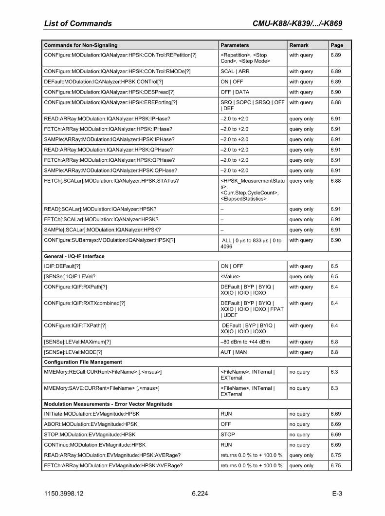
List of Commands CMU-K88/-K839/.../-K869
1150.3998.12 6.224 E-3
Commands for Non-Signaling Parameters Remark Page
CONFigure:MODulation:IQANalyzer:HPSK:CONTrol:REPetition[?] <Repetition>, <Stop Cond>, <Step Mode>
with query 6.89
CONFigure:MODulation:IQANalyzer:HPSK:CONTrol:RMODe[?] SCAL | ARR with query 6.89
DEFault:MODulation:IQANalyzer:HPSK:CONTrol[?] ON | OFF with query 6.89
CONFigure:MODulation:IQANalyzer:HPSK:DESPread[?] OFF | DATA with query 6.90
CONFigure:MODulation:IQANalyzer:HPSK:EREPorting[?] SRQ | SOPC | SRSQ | OFF | DEF
with query 6.88
READ:ARRay:MODulation:IQANalyzer:HPSK:IPHase? –2.0 to +2.0 query only 6.91
FETCh:ARRay:MODulation:IQANalyzer:HPSK:IPHase? –2.0 to +2.0 query only 6.91
SAMPle:ARRay:MODulation:IQANalyzer:HPSK:IPHase? –2.0 to +2.0 query only 6.91
READ:ARRay:MODulation:IQANalyzer:HPSK:QPHase? –2.0 to +2.0 query only 6.91
FETCh:ARRay:MODulation:IQANalyzer:HPSK:QPHase? –2.0 to +2.0 query only 6.91
SAMPle:ARRay:MODulation:IQANalyzer:HPSK:QPHase? –2.0 to +2.0 query only 6.91
FETCh[:SCALar]:MODulation:IQANalyzer:HPSK:STATus? <HPSK_MeasurementStatus>, <Curr.Step.CycleCount>, <ElapsedStatistics>
query only 6.88
READ[:SCALar]:MODulation:IQANalyzer:HPSK? – query only 6.91
FETCh[:SCALar]:MODulation:IQANalyzer:HPSK? – query only 6.91
SAMPle[:SCALar]:MODulation:IQANalyzer:HPSK? – query only 6.91
CONFigure:SUBarrays:MODulation:IQANalyzer:HPSK[?] ALL | 0 µs to 833 µs | 0 to 4096
with query 6.90
General - I/Q-IF Interface
IQIF:DEFault[?] ON | OFF with query 6.5
[SENSe:]:IQIF:LEVel? <Value> query only 6.5
CONFigure:IQIF:RXPath[?] DEFault | BYP | BYIQ | XOIO | IOIO | IOXO
with query 6.4
CONFigure:IQIF:RXTXcombined[?] DEFault | BYP | BYIQ | XOIO | IOIO | IOXO | FPAT | UDEF
with query 6.4
CONFigure:IQIF:TXPath[?] DEFault | BYP | BYIQ | XOIO | IOIO | IOXO
with query 6.4
[SENSe]:LEVel:MAXimum[?] –80 dBm to +44 dBm with query 6.8
[SENSe]:LEVel:MODE[?] AUT | MAN with query 6.8
Configuration File Management
MMEMory:RECall:CURRent<FileName> [,<msus>] <FileName>, INTernal | EXTernal
no query 6.3
MMEMory:SAVE:CURRent<FileName> [,<msus>] <FileName>, INTernal | EXTernal
no query 6.3
Modulation Measurements - Error Vector Magnitude
INITiate:MODulation:EVMagnitude:HPSK RUN no query 6.69
ABORt:MODulation:EVMagnitude:HPSK OFF no query 6.69
STOP:MODulation:EVMagnitude:HPSK STOP no query 6.69
CONTinue:MODulation:EVMagnitude:HPSK RUN no query 6.69
READ:ARRay:MODulation:EVMagnitude:HPSK:AVERage? returns 0.0 % to + 100.0 % query only 6.75
FETCh:ARRay:MODulation:EVMagnitude:HPSK:AVERage? returns 0.0 % to + 100.0 % query only 6.75

CMU-K88/-K839/.../-K869 List of Commands
1150.3998.12 6.225 E-3
Commands for Non-Signaling Parameters Remark Page
SAMPle:ARRay:MODulation:EVMagnitude:HPSK:AVERage? returns 0.0 % to + 100.0 % query only 6.75
READ:SUBarrays:MODulation:EVMagnitude:HPSK:AVERage? returns 0.0 % to + 100.0 % query only 6.75
FETCh:SUBarrays:MODulation:EVMagnitude:HPSK:AVERage? returns 0.0 % to + 100.0 % query only 6.75
SAMPle:SUBarrays:MODulation:EVMagnitude:HPSK:AVERage? returns 0.0 % to + 100.0 % query only 6.75
CONFigure:MODulation:EVMagnitude:HPSK:CONTrol:REPetition[?] <Repetition> ,<Stop Cond>, <Step Mode>
with query 6.72
CONFigure:MODulation:EVMagnitude:HPSK:CONTrol:RMODe[?] SCAL | ARR with query 6.71
CONFigure:MODulation:EVMagnitude:HPSK:CONTrol:STATistics[?] 1 to 1000 with query 6.71
CONFigure:MODulation:EVMagnitude:HPSK:CONTrol[?] <Statistics Count>, <Repetition>, <Stop Cond>, <Step Mode>
with query 6.72
DEFault:MODulation:EVMagnitude:HPSK:CONTrol[?] ON | OFF with query 6.72
READ:ARRay:MODulation:EVMagnitude:HPSK:CURRent? returns 0.0 % to + 100.0 % query only 6.75
FETCh:ARRay:MODulation:EVMagnitude:HPSK:CURRent? returns 0.0 % to + 100.0 % query only 6.75
SAMPle:ARRay:MODulation:EVMagnitude:HPSK:CURRent? returns 0.0 % to + 100.0 % query only 6.75
READ:SUBarrays:MODulation:EVMagnitude:HPSK:CURRent? returns 0.0 % to + 100.0 % query only 6.75
FETCh:SUBarrays:MODulation:EVMagnitude:HPSK:CURRent? returns 0.0 % to + 100.0 % query only 6.75
SAMPle:SUBarrays:MODulation:EVMagnitude:HPSK:CURRent? returns 0.0 % to + 100.0 % query only 6.75
CONFigure:MODulation:EVMagnitude:HPSK:EREPorting[?] SRQ | SOPC | SRSQ | OFF | DEF
with query 6.70
CALCulate[:SCALar]:MODulation:EVMagnitude:HPSK:MATChing:LIMit? NMAU | NMAL | INV | OK query only 6.74
READ:ARRay:MODulation:EVMagnitude:HPSK:MMAX? returns 0.0 % to + 100.0 % query only 6.75
FETCh:ARRay:MODulation:EVMagnitude:HPSK:MMAX? returns 0.0 % to + 100.0 % query only 6.75
SAMPle:ARRay:MODulation:EVMagnitude:HPSK:MMAX? returns 0.0 % to + 100.0 % query only 6.75
READ:SUBarrays:MODulation:EVMagnitude:HPSK:MMAX? returns 0.0 % to + 100.0 % query only 6.75
FETCh:SUBarrays:MODulation:EVMagnitude:HPSK:MMAX? returns 0.0 % to + 100.0 % query only 6.75
SAMPle:SUBarrays:MODulation:EVMagnitude:HPSK:MMAX? returns 0.0 % to + 100.0 % query only 6.75
FETCh[:SCALar]:MODulation:EVMagnitude:HPSK:STATus? <HPSK_MeasurementStatus>, <Curr.Step.CycleCount>, <ElapsedStatistics>
query only 6.70
READ[:SCALar]:MODulation:EVMagnitude:HPSK? <HPSK_EVM_MeasValues_Set>
query only 6.74
FETCh[:SCALar]:MODulation:EVMagnitude:HPSK? <HPSK_EVM_MeasValues_Set>
query only 6.74
SAMPle[:SCALar]:MODulation:EVMagnitude:HPSK? <HPSK_EVM_MeasValues_Set>
query only 6.74
CONFigure:SUBarrays:MODulation:EVMagnitude:HPSK[?] <Mode>, <Start>, <Samples>
with query 6.73
Modulation - Magnitude Error H-PSK
INITiate:MODulation:MERRor:HPSK RUN no query 6.76
ABORt:MODulation:MERRor:HPSK OFF no query 6.76
STOP:MODulation:MERRor:HPSK STOP no query 6.76
CONTinue:MODulation:MERRor:HPSK RUN no query 6.76
READ:ARRay:MODulation:MERRor:HPSK:AVERage? returns 0.0 % to + 100.0 % query only 6.81
FETCh:ARRay:MODulation:MERRor:HPSK:AVERage? returns 0.0 % to + 100.0 % query only 6.81

List of Commands CMU-K88/-K839/.../-K869
1150.3998.12 6.226 E-3
Commands for Non-Signaling Parameters Remark Page
SAMPle:ARRay:MODulation:MERRor:HPSK:AVERage? returns 0.0 % to + 100.0 % query only 6.81
READ:SUBarrays:MODulation:MERRor:HPSK:AVERage? returns 0.0 % to + 100.0 % query only 6.81
FETCh:SUBarrays:MODulation:MERRor:HPSK:AVERage? returns 0.0 % to + 100.0 % query only 6.81
SAMPle:SUBarrays:MODulation:MERRor:HPSK:AVERage? returns 0.0 % to + 100.0 % query only 6.81
CONFigure:MODulation:MERRor:HPSK:CONTrol:REPetition[?] <Repetition>, <Stop Cond>, <Step Mode>
with query 6.78
CONFigure:MODulation:MERRor:HPSK:CONTrol:RMODe[?] SCAL | ARR with query 6.77
CONFigure:MODulation:MERRor:HPSK:CONTrol:STATistics[?] 1 to 1000 with query 6.78
CONFigure:MODulation:MERRor:HPSK:CONTrol[?] <Result Mode>, <Statistics Count>, <Repetition>, <Stop Cond>, <Step Mode>
with query 6.77
DEFault:MODulation:MERRor:HPSK:CONTrol[?] ON | OFF with query 6.78
READ:ARRay:MODulation:MERRor:HPSK:CURRent? returns 0.0 % to + 100.0 % query only 6.81
FETCh:ARRay:MODulation:MERRor:HPSK:CURRent? returns 0.0 % to + 100.0 % query only 6.81
SAMPle:ARRay:MODulation:MERRor:HPSK:CURRent? returns 0.0 % to + 100.0 % query only 6.81
READ:SUBarrays:MODulation:MERRor:HPSK:CURRent? returns 0.0 % to + 100.0 % query only 6.81
FETCh:SUBarrays:MODulation:MERRor:HPSK:CURRent? returns 0.0 % to + 100.0 % query only 6.81
SAMPle:SUBarrays:MODulation:MERRor:HPSK:CURRent? returns 0.0 % to + 100.0 % query only 6.81
CONFigure:MODulation:MERRor:HPSK:EREPorting[?] SRQ | SOPC | SRSQ | OFF | DEF
with query 6.76
CALCulate[:SCALar]:MODulation:MERRor:HPSK:MATChing:LIMit? NMAU | NMAL | INV | OK query only 6.80
READ:ARRay:MODulation:MERRor:HPSK:MMAX? returns 0.0 % to + 100.0 % query only 6.81
FETCh:ARRay:MODulation:MERRor:HPSK:MMAX? returns 0.0 % to + 100.0 % query only 6.81
SAMPle:ARRay:MODulation:MERRor:HPSK:MMAX? returns 0.0 % to + 100.0 % query only 6.81
READ:SUBarrays:MODulation:MERRor:HPSK:MMAX? returns 0.0 % to + 100.0 % query only 6.81
FETCh:SUBarrays:MODulation:MERRor:HPSK:MMAX? returns 0.0 % to + 100.0 % query only 6.81
SAMPle:SUBarrays:MODulation:MERRor:HPSK:MMAX? returns 0.0 % to + 100.0 % query only 6.81
FETCh[:SCALar]:MODulation:MERRor:HPSK:STATus? <HPSK_MeasurementStatus>, <Curr.Step.CycleCount>, <ElapsedStatistics>
query only 6.76
READ[:SCALar]:MODulation:MERRor:HPSK? returns <HPSK_ME_MeasValues_Set>
query only 6.80
FETCh[:SCALar]:MODulation:MERRor:HPSK? returns <HPSK_ME_MeasValues_Set>
query only 6.80
SAMPle[:SCALar]:MODulation:MERRor:HPSK? returns <HPSK_ME_MeasValues_Set>
query only 6.80
CONFigure:SUBarrays:MODulation:MERRor:HPSK[?] ALL | ARIT | MIN | MAX | 0 µs to 833 µs | 0 to 1024
with query 6.79
CONFigure:MODulation:OEMP:HPSK:AVERage:LIMit[:SCALar]:SYMMetric[:COMBined]:VALue[?]
<Average_HPSK_Limit_Set>
with query 6.67
CONFigure:MODulation:OEMP:HPSK:AVERage:LIMit[:SCALar]:SYMMetric[:COMBined]:ENABle[?]
ON | OFF with query 6.67
CONFigure:MODulation:OEMP:HPSK:AVERage:LIMit[:SCALar]:SYMMetri <Average_OQPSK_Limits_ with query 6.66

CMU-K88/-K839/.../-K869 List of Commands
1150.3998.12 6.227 E-3
Commands for Non-Signaling Parameters Remark Page c[:COMBined][?] DefaultSettings>
CONFigure:MODulation:OEMP:HPSK:CMMax:LIMit[:SCALar]:SYMMetric[:COMBined]:ENABle[?]
ON | OFF with query 6.67
CONFigure:MODulation:OEMP:HPSK:CMMax:LIMit[:SCALar]:SYMMetric[:COMBined]:VALue[?]
<CMMAX_OQPSK_Limits_DefaultSettings>
with query 6.66
CONFigure:MODulation:OEMP:HPSK:CMMax:LIMit[:SCALar]:SYMMetric[:COMBined][?]
<CMMAX_OQPSK_Limits_DefaultSettings>
with query 6.65
DEFault:MODulation:OEMP:HPSK:LIMit[?] ON | OFF with query 6.68
INITiate:MODulation:OVERview:HPSK RUN no query 6.61
ABORt:MODulation:OVERview:HPSK OFF no query 6.61
CONTinue:MODulation:OVERview:HPSK RUN no query 6.61
STOP:MODulation:OVERview:HPSK STOP no query 6.61
CONFigure:MODulation:OVERview:HPSK:CONTrol:REPetition[?] <Repetition>, <Stop Cond>, <Step Mode>
with query 6.64
CONFigure:MODulation:OVERview:HPSK:CONTrol:STATistics[?] 1 to 1000 with query 6.64
DEFault:MODulation:OVERview:HPSK:CONTrol[?] ON | OFF with query 6.63
CONFigure:MODulation:OVERview:HPSK:CONTrol[?] <Statistic Count>, <Repetition>, <Stop Cond>, <Step Mode>
with query 6.63
CONFigure:MODulation:OVERview:HPSK:EREPorting[?] SRQ | SOPC | SRSQ | OFF | DEF
with query 6.62
CALCulate[:SCALar]:MODulation:OVERview:HPSK:MATChing:LIMit? NMAU | NMAL | INV | OK query only 6.69
FETCh[:SCALar]:MODulation:OVERview:HPSK:STATus? <HPSK_MeasurementStatus>, <Curr.Step.CycleCount>, <ElapsedStatistics>
query only 6.62
READ[:SCALar]:MODulation:OVERview:HPSK? <OvwHPSK_MeasValues_Set>
query only 6.68
FETCh[:SCALar]:MODulation:OVERview:HPSK? <OvwHPSK_MeasValues_Set>
query only 6.68
SAMPle[:SCALar]:MODulation:OVERview:HPSK? <OvwHPSK_MeasValues_Set>
query only 6.68
Modulation Phase Error
INITiate:MODulation:PERRor:HPSK RUN no query 6.82
ABORt:MODulation:PERRor:HPSK OFF no query 6.82
STOP:MODulation:PERRor:HPSK STOP no query 6.82
CONTinue:MODulation:PERRor:HPSK RUN no query 6.82
READ:ARRay:MODulation:PERRor:HPSK:AVERage? –100.0 deg to + 100.0 deg query only 6.87
FETCh:ARRay:MODulation:PERRor:HPSK:AVERage? –100.0 deg to + 100.0 deg query only 6.87
SAMPle:ARRay:MODulation:PERRor:HPSK:AVERage? –100.0 deg to + 100.0 deg query only 6.87
READ:SUBarrays:MODulation:PERRor:HPSK:AVERage? –100.0 deg to + 100.0 deg query only 6.87
FETCh:SUBarrays:MODulation:PERRor:HPSK:AVERage? –100.0 deg to + 100.0 deg query only 6.87
SAMPle:SUBarrays:MODulation:PERRor:HPSK:AVERage? –100.0 deg to + 100.0 deg query only 6.87
CONFigure:MODulation:PERRor:HPSK:CONTrol:REPetition[?] <Repetition>, <Stop Cond>, <Step Mode>
with query 6.84
CONFigure:MODulation:PERRor:HPSK:CONTrol:RMODe[?] SCAL | ARR with query 6.84
CONFigure:MODulation:PERRor:HPSK:CONTrol:STATistics[?] 1 to 1000 with query 6.83

List of Commands CMU-K88/-K839/.../-K869
1150.3998.12 6.228 E-3
Commands for Non-Signaling Parameters Remark Page
CONFigure:MODulation:PERRor:HPSK:CONTrol[?] <Result Mode>, <Statistics Count>, <Repetition>, <Stop Cond>, <Step Mode>
with query 6.83
DEFault:MODulation:PERRor:HPSK:CONTrol[?] ON | OFF with query 6.84
READ:ARRay:MODulation:PERRor:HPSK:CURRent? –100.0 deg to + 100.0 deg query only 6.87
FETCh:ARRay:MODulation:PERRor:HPSK:CURRent? –100.0 deg to + 100.0 deg query only 6.87
SAMPle:ARRay:MODulation:PERRor:HPSK:CURRent? –100.0 deg to + 100.0 deg query only 6.87
READ:SUBarrays:MODulation:PERRor:HPSK:CURRent? –100.0 deg to + 100.0 deg query only 6.87
FETCh:SUBarrays:MODulation:PERRor:HPSK:CURRent? –100.0 deg to + 100.0 deg query only 6.87
SAMPle:SUBarrays:MODulation:PERRor:HPSK:CURRent? –100.0 deg to + 100.0 deg query only 6.87
CONFigure:MODulation:PERRor:HPSK:EREPorting[?] SRQ | SOPC | SRSQ | OFF | DEF
with query 6.82
CALCulate[:SCALar]:MODulation:PERRor:HPSK:MATChing:LIMit? NMAU | NMAL | INV | OK query only 6.86
READ:ARRay:MODulation:PERRor:HPSK:MMAX? –100.0 deg to + 100.0 deg query only 6.87
FETCh:ARRay:MODulation:PERRor:HPSK:MMAX? –100.0 deg to + 100.0 deg query only 6.87
SAMPle:ARRay:MODulation:PERRor:HPSK:MMAX? –100.0 deg to + 100.0 deg query only 6.87
READ:SUBarrays:MODulation:PERRor:HPSK:MMAX? –100.0 deg to + 100.0 deg query only 6.87
FETCh:SUBarrays:MODulation:PERRor:HPSK:MMAX? –100.0 deg to + 100.0 deg query only 6.87
SAMPle:SUBarrays:MODulation:PERRor:HPSK:MMAX? –100.0 deg to + 100.0 deg query only 6.87
FETCh[:SCALar]:MODulation:PERRor:HPSK:STATus? <HPSK_MeasurementStatus>, <Curr.Step.CycleCount>, <ElapsedStatistics>
query only 6.82
READ[:SCALar]:MODulation:PERRor:HPSK? returns <HPSK_EVM_MeasValues_Set>
query only 6.86
FETCh[:SCALar]:MODulation:PERRor:HPSK? returns <HPSK_EVM_MeasValues_Set>
query only 6.86
SAMPle[:SCALar]:MODulation:PERRor:HPSK? returns <HPSK_EVM_MeasValues_Set>
query only 6.86
CONFigure:SUBarrays:MODulation:PERRor:HPSK[?] ALL | ARIT | MIN | MAX | 0 µs to 833 µs | 0 to 1024
with query 6.85
Modulation Quality
INITiate:MODulation:MQUality:HPSK RUN no query 6.47
ABORt:MODulation:MQUality:HPSK OFF no query 6.47
STOP:MODulation:MQUality:HPSK STOP no query 6.47
CONTinue:MODulation:MQUality:HPSK RUN no query 6.47
CONFigure:MODulation:MQUality:HPSK:AVERage:LIMit[?] <Average modulation quality limits>
with query 6.52
DEFault:MODulation:MQUality:HPSK:AVERage:LIMit[?] ON | OFF with query 6.53
CONFigure:MODulation:MQUality:HPSK:CMMax:LIMit[?] <Curr. and max. modulation quality limits>
with query 6.51
DEFault:MODulation:MQUality:HPSK:CMMax:LIMit[?] ON | OFF with query 6.53
CONFigure:MODulation:MQUality:HPSK:CONTrol:FOFFset:SBSuppress:ACP<nr>[?]
0 to 2 MHz with query 6.52

CMU-K88/-K839/.../-K869 List of Commands
1150.3998.12 6.229 E-3
Commands for Non-Signaling Parameters Remark Page
CONFigure:MODulation:MQUality:HPSK:CONTrol:REPetition[?] <Repetition>, <Stop Cond>, <Step Mode>
with query 6.50
CONFigure:MODulation:MQUality:HPSK:CONTrol:STATistics[?] 1 to 1000 with query 6.49
DEFault:MODulation:MQUality:HPSK:CONTrol[?] ON | OFF with query 6.48
CONFigure:MODulation:MQUality:HPSK:CONTrol[?] <Statistics>, <Repetition>, <Stop Cond>, <Step Mode>
with query 6.49
CONFigure:MODulation:MQUality:HPSK:EREPorting[?] SRQ | SOPC | SRSQ | OFF | DEF
with query 6.47
CALCulate[:SCALar]:MODulation:MQUality:HPSK:MATChing:LIMIt? <OQPSK_MeasValues_Set>
query only 6.55
FETCh[:SCALar]:MODulation:MQUality:HPSK:STATus? <MeasurementStatus>, <Curr.Step.CycleCount>, <ElapsedStatistics>
query only 6.48
READ[:SCALar]:MODulation:MQUality:HPSK? <OQPSK_MeasValues_Set>
query only 6.54
FETCh[:SCALar]:MODulation:MQUality:HPSK? <OQPSK_MeasValues_Set>
query only 6.54
SAMPle[:SCALar]:MODulation:MQUality:HPSK? <OQPSK_MeasValues_Set>
query only 6.54
Network
CONFigure:NETWork:STANdard[?] USC | KCEL | NAPC | TACS | JTAC | KPCS | N45T | IM2K | NA7C | B18M | NA9C | NA8S | PA4M | PA8M | IEXT | USPC | AWS
with query 6.7
Narrow Band Power
INITiate:NPOWer RUN no query 6.56
ABORt:NPOWer OFF no query 6.56
STOP:NPOWer STOP no query 6.56
CONTinue:NPOWer RUN no query 6.56
CONFigure:NPOWer:CONTrol:REPetition[?] <Repetition>, <Stop Condition>, <Step Mode>
with query 6.59
CONFigure:NPOWer:CONTrol:STATistics[?] 1 to 1000 with query 6.58
CONFigure:NPOWer:CONTrol[?] <Statistics>, <Repetition>, <Stop Condition>, <Step Mode>
with query 6.58
CONFigure:NPOWer:EREPorting[?] SRQ | SOPC | SRSQ | OFF | DEF
with query 6.56
FETCh[:SCALar]:NPOWer:STATus? <MeasurementStatus>, <Curr.Step.CycleCount>, <ElapsedStatistics>
query only 6.57
READ[:SCALar]:NPOWer? –137 dBm to +53 dBm query only 6.60
FETCh[:SCALar]:NPOWer? –137 dBm to +53 dBm query only 6.60
SAMPle[:SCALar]:NPOWer? –137 dBm to +53 dBm query only 6.60
ABORt:CDPower:PCDep OFF no query 6.111
CONTinue:CDPower:PCDep STOP no query 6.111
Reset
SYSTem:RESet:CURRent – no query 6.2

List of Commands CMU-K88/-K839/.../-K869
1150.3998.12 6.230 E-3
Commands for Non-Signaling Parameters Remark Page
Analyzer
DEFault:RFANalyzer[?] ON | OFF with query 6.8
[SENSe]:RFANalyzer: [AT<nr>]>:RLINk:FROFfset[?] 0 to 15 with query 6.14
[SENSe]:RFANalyzer:CCFilter:ACK[?] ON | OFF| DCARe with query 6.12
[SENSe]:RFANalyzer:CCFilter:ADSC[?] OFF | ACK | DSC | DCARe with query 6.12
[SENSe]:RFANalyzer:CCFilter:APILot[?] ON | OFF| DCARe with query 6.12
[SENSe]:RFANalyzer:CCFilter:DATA[?] ON | OFF| DCARe with query 6.12
[SENSe]:RFANalyzer:CCFilter:DRC[?] ON | OFF| DCARe with query 6.12
[SENSe]:RFANalyzer:CCFilter:HSLot[?] BOTH | 1 | 2 with query 6.13
[SENSe]:RFANalyzer:DCHannel:MTYPe:MODE[?] AUTO | B4 | Q4 | Q2 | Q4Q2 | E4E2
with query 6.14
[SENSe]:RFANalyzer:DCHannel:MTYPe? B4 | Q4 | Q2 | Q4Q2 | E4E2 query only 6.15
[SENSe]:RFANalyzer:FOFFset[?] -50.0 kHz to +50.0 kHz | ON | OFF
with query 6.10
[SENSe]:RFANalyzer:FREQuency:UNIT[?] HZ | KHZ | MHZ | GHZ | CH with query 6.9
[SENSe]:RFANalyzer:FREQuency[?] 9.98 MHz to 2700.00 MHz with query 6.9
[SENSe]:RFANalyzer:LCMask:I:LSB[?] 00000000 to FFFFFFFF with query 6.11
[SENSe]:RFANalyzer:LCMask:I:MSB[?] 000 to 3FF with query 6.11
[SENSe]:RFANalyzer:LCMask:Q:LSB[?] 00000000 to FFFFFFFF with query 6.11
[SENSe]:RFANalyzer:LCMask:Q:MSB[?] 000 to 3FF with query 6.11
[SENSe]:RFANalyzer:Selectivity[?] WIDE | IFL | DEF with query 6.45
[SENSe]:RFANalyzer:Subtype[?] 0 to 2 with query 6.11
Generator
INITiate:RFGenerator – no query 6.15
ABORt:RFGenerator – no query 6.15
INITiate:RFGenerator: SNCMessage RUN | ON no query 6.20
SOURce:RFGenerator:AT<nr>:DRATe? 0.0 to 2457.6 kBit/s query only 6.28
SOURce:RFGenerator:AT<nr>:DRCLock:LENGth[?] 1 | 4 | 8 | 16 | 32 | MIN | MAX | DEF
with query 6.28
SOURce:RFGenerator:AT<nr>:DRCLock:PERiod[?] 0 | 4 | 8 | 16 | MIN | MAX | DEF
with query 6.29
SOURce:RFGenerator:AT<nr>:DRCLock:STATe[?] 0 to 1 | MIN | MAX | DEF with query 6.29
SOURce:RFGenerator:AT<nr>:DRINdex[?] 1 to 12 | MIN | MAX | DEF with query 6.26
SOURce:RFGenerator:AT<nr>:HARQ:MODe[?] ACK | NACK with query 6.30
SOURce:RFGenerator:AT<nr>:IFACtor 1 to 4 | MIN | MAX | DEF no query 6.25
INITiate:RFGenerator:AT<nr>:MAC:INDex RUN | ON no query 6.22
ABORt:RFGenerator:AT<nr>:MAC:INDex OFF no query 6.22
SOURce:RFGenerator:AT<nr>:MAC:INDex[?] 5 to 63 with query 6.23
SOURce:RFGenerator:AT<nr>:MAC:LEVel[?] –25.0 dB to –7.0 dB with query 6.23
SOURce:RFGenerator:AT<nr>:PATTern[?] 00000000 to FFFFFFFF with query 6.29
PROCedure:RFGenerator:AT<nr>:PCBits:PATTern[?] INJ | RDY with query 6.30
SOURce:RFGenerator:AT<nr>:PCBits:RTES:NOBits[?] 1 to 256 | MIN | MAX | DEF
with query 6.31

CMU-K88/-K839/.../-K869 List of Commands
1150.3998.12 6.231 E-3
Commands for Non-Signaling Parameters Remark Page
SOURce:RFGenerator:AT<nr>:PCBits[?] HOLD | ADOW | AUP | RTES | PATT | DEF
with query 6.31
SOURce:RFGenerator:AT<nr>:PCOunt[?] 0 to 65535 | INF | MIN | MAX | DEF
with query 6.24
SOURce:RFGenerator:AT<nr>:PSIZe? 128 to 5120 bits query only 6.28
SOURce:RFGenerator:AT<nr>:PSOFfset[?] 0 to +255 | MIN | MAX | DEF
with query 6.25
INITiate:RFGenerator:AT<nr>:PSTReam RUN | ON no query 6.23
ABORt:RFGenerator:AT<nr>:PSTReam OFF no query 6.24
FETCh:RFGenerator:AT<nr>:PSTReam:STATus? returns OFF | ON | RUN | RDY | 0 to 65535
query only 6.24
SOURce:RFGenerator:AT<nr>:PTINdex[?] 1 to 37 | MIN | MAX | DEF with query 6.27
SOURce:RFGenerator:AT<nr>:SCOunt? 0 to 16 query only 6.28
SOURce:RFGenerator:AT<nr1>:PCBits:PATTern:AREA<nr2>:NOBits[?] 1 to 128 | DEF with query 6.32
SOURce:RFGenerator:AT<nr1>:PCBits:PATTern:AREA<nr2>:POLarity[?] UP | DOWN with query 6.32
SOURce:RFGenerator:DRATe? 0.0 to 3072 kBit/s query only 6.28
SOURce:RFGenerator:DRCLock:LENGth[?] 4 | 8 | 16 | 32 | MIN | MAX | DEF
with query 6.30
SOURce:RFGenerator:DRCLock:PERiod[?] 8 | 16 | MIN | MAX | DEF with query 6.30
SOURce:RFGenerator:DRINdex[?] 1 to 12 (or 14) | MIN | MAX | DEF
with query 6.26
CONFigure:RFGenerator:FPACtivity[?] 0% t o 100% with query 6.29
SOURce:RFGenerator:FREQuency[:RF]:UNIT[?] HZ | KHZ | MHZ | GHZ | CH with query 6.16
SOURce:RFGenerator:FREQuency[:RF][?] 9.98 MHz to 2700.00 MHz with query 6.16
INITiate:RFGenerator:MAC:INDex RUN | ON no query 6.22
ABORt:RFGenerator:MAC:INDex OFF no query 6.22
FETCh:RFGenerator:MAC:INDex:STATus? returns OFF | ON | RUN query only 6.22
SOURce:RFGenerator:MAC:INDex[:REV0][?] 5 to 63 with query 6.23
SOURce:RFGenerator:MAC:INDex[:REVA][?] 5 to 63 | 72 to 127 with query 6.23
SOURce:RFGenerator:MAC:LEVel[?] –25.0 dB to –7.0 dB query only 6.23
SOURce:RFGenerator:MODE[?] NORM | CPIL | DEF with query 6.18
SOURce:RFGenerator:OAT:COUNt[?] 1 to 55 (or 110) with query 6.34
SOURce:RFGenerator:PATTern[?] 00000000 to FFFFFFFF with query 6.29
SOURce:RFGenerator:PCBits[?] HOLD | ADOW | AUP | EXT | DEF
with query 6.31
SOURce:RFGenerator:PCOunt[?] 0 to 65535 | INF | MIN | MAX | DEF
with query 6.24
SOURce:RFGenerator:POWer:OUTPut[?] –120.0 dBm to +5.0 dBm with query 6.18
SOURce:RFGenerator:PROPerty:PNOFfset[?] 0 to +511 with query 6.18
SOURce:RFGenerator:PSIZe? 128 to 5120 bits query only 6.28
INITiate:RFGenerator:PSTReam RUN | ON no query 6.23
ABORt:RFGenerator:PSTReam OFF no query 6.24
FETCh:RFGenerator:PSTReam:STATus? returns OFF | ON | RUN | RDY | 0 to 65535
query only 6.24
SOURce:RFGenerator:PTINdex[?] 1 to 37 | MIN | MAX | DEF with query 6.27

List of Commands CMU-K88/-K839/.../-K869
1150.3998.12 6.232 E-3
Commands for Non-Signaling Parameters Remark Page
SOURce:RFGenerator:RAB:LENGth[?] 8 | 16 | 32 | 64 with query 6.33
SOURce:RFGenerator:RAB:MAC:LEVel[?] –25.0 dB to –7.0 dB with query 6.32
SOURce:RFGenerator:RAB:OFFSet[?] 0 to 7 with query 6.33
SOURce:RFGenerator:RAB:STATe[?] 0 | 1 with query 6.33
SOURce:RFGenerator:SCOunt? 0 to 16 query only 6.28
ABORt:RFGenerator:SNCMessage OFF no query 6.20
SOURce:RFGenerator:SNCMessage:DRATe? 38.4 to 76.8 kBit/s query only 6.21
SOURce:RFGenerator:SNCMessage:DRINdex[?] 1 to 2 with query 6.21
SOURce:RFGenerator:SNCMessage:PSOFfset[?] 0 to 3 with query 6.21
SOURce:RFGenerator:SNCMessage:SCOunt? 8 to 16 query only 6.22
FETCh:RFGenerator:SNCMessage:STATus? returns OFF | ON | RUN query only 6.21
FETCh:RFGenerator:STATus? returns OFF | RUN | ERR query only 6.16
SOURce:RFGenerator:SUBType[?] 0 | 1 | 2 | DEF with query 6.19
SOURce:RFGenerator:Type? B88 | B89 query only 6.34
DEFault:RFGenerator[?] ON | OFF with query 6.15
Standby Power / Access Probe Power
INITiate:SAPPower RUN no query 6.60
ABORt:SAPPower OFF no query 6.60
STOP:SAPPower STOP no query 6.60
CONTinue:SAPPower RUN no query 6.60
CONFigure:SAPPower:EREPorting[?] SRQ | SOPC | SRSQ | OFF with query 6.60
FETCh[:SCALar]:SAPPower:STATus? OFF | RUN | STOP | ERR | STEP | RDY
query only 6.61
READ[:SCALar]:SAPPower? <Standby Power>, <Access Probe Power>
query only 6.61
FETCh[:SCALar]:SAPPower? <Standby Power>, <Access Probe Power>
query only 6.61
SAMPle[:SCALar]:SAPPower? <Standby Power>, <Access Probe Power>
query only 6.61
DM:Clock
SOURce:DM:CLOCk:FREQuency[?] 39.3216 MHz | 19.6608 MHz | 13.1072 MHz | 9.8304 MHz
with query 6.40
SOURce:DM:CLOCk:STATe[?] ON | OFF with query 6.40
ACP Spectrum
INITiate:SPECtrum:ACP RUN no query 6.92
ABORt:SPECtrum:ACP OFF no query 6.92
STOP:SPECtrum:ACP STOP no query 6.92
CONTinue:SPECtrum:ACP RUN no query 6.92
CONFigure:SPECtrum:ACP:CONTrol:FOFFset:ACP<nr>[?] 0 to 2 MHz | OFF | ON with query 6.95
CONFigure:SPECtrum:ACP:CONTrol:REPetition[?] <Repetition>, <Stop Cond>, <Step Mode>
with query 6.94
CONFigure:SPECtrum:ACP:CONTrol:STATistics[?] 1 to 1000 with query 6.93

CMU-K88/-K839/.../-K869 List of Commands
1150.3998.12 6.233 E-3
Commands for Non-Signaling Parameters Remark Page
CONFigure:SPECtrum:ACP:CONTrol[?] <StatisticCount>, <Repetition>, <Stop Cond>, <Step Mode>
with query 6.93
DEFault:SPECtrum:ACP:CONTrol[?] ON | OFF with query 6.94
CONFigure:SPECtrum:ACP:EREPorting[?] SRQ | SOPC | SRSQ | DEF | OFF
with query 6.92
CONFigure:SPECtrum:ACP:LIMit:ACP1[?] –80.0 to +10.0 | ON | OFF | MIN | MAX | DEF
with query 6.97
XTND:SPECtrum:ACP:LIMit[?] ON | OFF | DEF with query 6.59
DEFault:SPECtrum:ACP:LIMit[?] ON | OFF with query 6.97
CALCulate[:SCALar]:SPECtrum:ACP:MATChing:LIMit? NMAU | NMAL | INV | OK query only 6.99
XTND:SPECtrum:ACP:STATistics[?] ON | OFF | DEF with query 6.97
FETCh[:SCALar]:SPECtrum:ACP:STATus? <MeasurementStatus>, <Curr.Step.CycleCount>, <ElapsedStatistics>
query only 6.92
READ[:SCALar]:SPECtrum:ACP? –80.0 dB to 0.0 dB query only 6.98
FETCh[:SCALar]:SPECtrum:ACP? –80.0 dB to 0.0 dB query only 6.98
SAMPle[:SCALar]:SPECtrum:ACP? –80.0 dB to 0.0 dB query only 6.98
Symbolic Status Event Register Evaluation
STATus:OPERation:SYMBolic:ENABle[?] <Event>,<Event> NONE | <Event>[,<Event>] no query 6.6
STATus:OPERation:SYMBolic[:EVENt]? <Event>,<Event> NONE | <Event>[,<Event>]
with query 6.6
General
SYSTem:OPTions:INFO:CURRent? - query only 6.2
SYSTem:VERSion:SW:MMI? - query only 6.2
Trigger
TRIGger:OUTPut:PIN<nr>:SIGNal[?] NONE | PP2S | CCH | SFH | CSL | ATRF | ATFS | SLOT | CPCP | IPCP | DEF
with query 6.42
TRIGger:SELect:AT[?] 1 to 4 wwith query 6.41
TRIGger[:SEQuence]:SLOPe[?] NEG | POS | DEF with query 6.41
TRIGger[:SEQuence]:SOURce[?] INT | EXT | FRUN | RFP | IFP | DEF
with query 6.41
TRIGger[:SEQuence]:THReshold:IFPower[?] -47.0 dB to 0 dB with query 6.43
TRIGger[:SEQuence]:THReshold:RFPower[?] LOW | MED | HIGH with query 6.43
DEFault:TRIGger[:SEQuence][?] ON | OFF with query 6.41
Wide Band Power
INITiate:WPOWer RUN no query 6.38
ABORt:WPOWer OFF no query 6.38
STOP:WPOWer STOP no query 6.38
CONTinue:WPOWer RUN no query 6.38
CONFigure:WPOWer:CONTrol:REPetition[?] <Repetition>,<StopCond>,<Stepmode>
with query 6.39
CONFigure:WPOWer:EREPorting[?] SRQ | SOPC | SRSQ | OFF
with query 6.38

List of Commands CMU-K88/-K839/.../-K869
1150.3998.12 6.234 E-3
Commands for Non-Signaling Parameters Remark Page
FETCh:WPOWer:STATus? returns <Measurement Status> and <Curr. Step Cycle Count>
query only 6.39
READ[:SCALar]:WPOWer? –30.0 dBm to +30.0 dBm query only 6.40
FETCh[:SCALar]:WPOWer? –30.0 dBm to +30.0 dBm query only 6.40
SAMPle[:SCALar]:WPOWer? –30.0 dBm to +30.0 dBm query only 6.40
Table 6-2 Remote-control commands available in Signaling
Commands for Signaling Parameters Remark Page
Access Network Signal
DEFault:ANSignal[?] ON | OFF | DEF with query 6.192 UNIT:ANSignal:CHANnel[:RF][?] CH | HZ | MHZ | KHZ | GHZ with query 6.192 CONFigure:ANSignal:CHANnel[:RF][?] \Value\ with query 6.193 CONFigure:ANSignal:FPACtivity[?] 0% to 100% with query 6.198 CONFigure:ANSignal:MAC:INDex:REVA[?] 5 to 127 with query 6.195 CONFigure:ANSignal:MAC:INDex[:REV0][?] 5 to 63 with query 6.195 CONFigure:ANSignal:PCBits:SSIZe[?] 0.5 dB | 1.0 dB | MIN |
MAX | DEF with query 6.195
CONFigure:ANSignal:PCBits[?] AUT | HOLD | ADOW | AUP | DEF
with query 6.194
CONFigure:ANSignal:POWer:EVDO[?] –150.0 dBm to +50.0 dBm with query 6.193 CONFigure:ANSignal:POWer:OUTPut? –150.0 dBm to +50.0 dBm query only 6.193 Configure:ANSignal:PROPerty:PNOFfset? .s to .s | ON | OFF with query 6.198 Configure:ANSignal:PROPerty:PNOFfset[?] 0 Hz to 511 Hz with query 6.197 CONFigure:ANSignal:SECTor:CLRCode[?] 0 to 255 with query 6.195 CONFigure:ANSignal:SECTor:CNTCode[?] 0 to 999 with query 6.197 Configure:ANSignal:SECTor:ID:FORMat[?] A41N | Manual with query 6.196 CONFigure:ANSignal:SECTor:ID:LBITs[?] <7 char hex> with query 6.196 [SENSe]:ANSignal:SECTor:ID:MANual[?] <34 char hex> with query 6.197 [SENSe]:ANSignal:SECTor:ID? <34 char hex> query only 6.196 CONFigure:ANSignal:SECTor:NPBits[?] <16 char hex> with query 6.196 CONFigure:ANSignal:SECTor:SMASk[?] 0 to 128 with query 6.197 Packet Application AT Support
[Sense]:ATINfo:APPLication:DPACket:Support? ON | OFF query only 6.173 AT Info
[SENSe]:ATINfo:ESN? <9 characters> query only 6.160 [SENSe]:ATINfo:MEID? <15 characters> query only 6.160 [SENSE]:ATINfo:PREFerred:CCHannel:CYCLe:ENABle? ON | OFF query only 6.160 [SENSE]:ATINfo:PREFerred:CCHannel:CYCLe? 0 to 32767 query only 6.160 [SENSe]:ATINfo:UATi? <17 characters> query only 6.160

CMU-K88/-K839/.../-K869 List of Commands
1150.3998.12 6.235 E-3
Commands for Signaling Parameters Remark Page
Handoff
PROCedure:BC:HANDoff[?] <Standard>, CH | HZ | KHZ | MHZ | GHZ
with query 6.161
Code Domain Power
INITiate:CDPower:CDPW RUN no query 6.100 ABORt:CDPower:CDPW OFF no query 6.100 STOP:CDPower:CDPW STOP no query 6.100 CONTinue:CDPower:CDPW RUN no query 6.100 CONFigure:CDPower:CDPW:AVERage:LIMit:ASYMmetric[:COMBined][?] <CDP Limit Y Average> with query 6.105 CALCulate:ARRay:CDPower:CDPW:AVERage[:RESult]:MATChing:LIMit? returns 64 bit limit indicator query only 6.110 CONFigure:CDPower:CDPW:CMAX:LIMit:ASYMmetric[:COMBined][?] <CDP Limit Y> with query 6.105 CONFigure:CDPower:CDPW:CONTrol:REPetition[?] <Repetition>, <Stop
Cond>, <Step Mode> with query 6.102
CONFigure:CDPower:CDPW:CONTrol:RMODe[?] SCAL | ARR with query 6.101 CONFigure:CDPower:CDPW:CONTrol:RORDer[?] HAD | BITR with query 6.102 CONFigure:CDPower:CDPW:CONTrol:STATistics[?] 1 to 1000 with query 6.102 CONFigure:CDPower:CDPW:CONTrol[?] <Result Mode>, <Current
Statistics>, <Repetition>, <Stop Cond>, <Step Mode>
with query 6.101
DEFault:CDPower:CDPW:CONTrol[?] ON | OFF with query 6.102 CALCulate:ARRay:CDPower:CDPW:CURRent[:RESult]:MATChing:LIMit? returns 64 bit limit indicator query only 6.109 CONFigure:CDPower:CDPW:EREPorting[?] SRQ | SOPC | SRSQ | DEF
| OFF with query 6.100
CALCulate:ARRay:CDPower:CDPW:ISIGnal:AVERage[:RESult]:MATChing:LIMit?(*)
returns 32 bit limit indicator query only 6.110
CALCulate:ARRay:CDPower:CDPW:ISIGnal:CURRent[:RESult]:MATChing:LIMit?(*)
returns 32 bit limit indicator query only 6.109
CALCulate:ARRay:CDPower:CDPW:ISIGnal:MAXimum[:RESult]:MATChing:LIMit?(*)
returns 32 bit limit indicator query only 6.110
FETCh:ARRay:CDPower:CDPW:ISIGnal:STATe?(*) 0 | 1 query only 6.109 READ:ARRay:CDPower:CDPW:ISIGnal[:VALue]:AVERage?(*) –60.0 dB to +10.0 dB query only 6.108 FETCh:ARRay:CDPower:CDPW:ISIGnal[:VALue]:AVERage?(*) –60.0 dB to +10.0 dB query only 6.108 SAMPle:ARRay:CDPower:CDPW:ISIGnal[:VALue]:AVERage?(*) –60.0 dB to +10.0 dB query only 6.108 FETCh:ARRay:CDPower:CDPW:ISIGnal[:VALue]:CURRent?(*) –60.0 dB to +10.0 dB query only 6.107 READ:ARRay:CDPower:CDPW:ISIGnal[:VALue]:CURRent?(*) –60.0 dB to +10.0 dB query only 6.107 SAMPle:ARRay:CDPower:CDPW:ISIGnal[:VALue]:CURRent?(*) –60.0 dB to +10.0 dB query only 6.107 READ:ARRay:CDPower:CDPW:ISIGnal[:VALue]:MAXimum?(*) –60.0 dB to +10.0 dB query only 6.108 FETCh:ARRay:CDPower:CDPW:ISIGnal[:VALue]:MAXimum?(*) –60.0 dB to +10.0 dB query only 6.108 SAMPle:ARRay:CDPower:CDPW:ISIGnal[:VALue]:MAXimum?(*) –60.0 dB to +10.0 dB query only 6.108 CONFigure:CDPower:CDPW:LIMit:IQLCheck[?] DEFault | OFF | ON with query 6.105 DEFault:CDPower:CDPW:LIMit[?] ON | OFF with query 6.106 CALCulate[:SCALar]:CDPower:CDPW:MATChing:LIMit? NMAU | NMAL | INV | OK query only 6.106 CALCulate:ARRay:CDPower:CDPW:MAXimum[:RESult]:MATChing:LIMit? returns 64 bit limit indicator query only 6.110

List of Commands CMU-K88/-K839/.../-K869
1150.3998.12 6.236 E-3
Commands for Signaling Parameters Remark Page
CALCulate:ARRay:CDPower:CDPW:QSIGnal:AVERage[:RESult]:MATChing:LIMit?(*)
returns 32 bit limit indicator query only 6.110
CALCulate:ARRay:CDPower:CDPW:QSIGnal:CURRent[:RESult]:MATChing:LIMit?(*)
returns 32 bit limit indicator query only 6.109
CALCulate:ARRay:CDPower:CDPW:QSIGnal:MAXimum[:RESult]:MATChing:LIMit?(*)
returns 32 bit limit indicator query only 6.110
FETCh:ARRay:CDPower:CDPW:QSIGnal:STATe?(*) 0 | 1 query only 6.109 READ:ARRay:CDPower:CDPW:QSIGnal[:VALue]:AVERage?(*) –60.0 dB to +10.0 dB query only 6.108 FETCh:ARRay:CDPower:CDPW:QSIGnal[:VALue]:AVERage?(*) –60.0 dB to +10.0 dB query only 6.108 SAMPle:ARRay:CDPower:CDPW:QSIGnal[:VALue]:AVERage?(*) –60.0 dB to +10.0 dB query only 6.108 READ:ARRay:CDPower:CDPW:QSIGnal[:VALue]:CURRent?(*) –60.0 dB to +10.0 dB query only 6.107 FETCh:ARRay:CDPower:CDPW:QSIGnal[:VALue]:CURRent?(*) –60.0 dB to +10.0 dB query only 6.107 SAMPle:ARRay:CDPower:CDPW:QSIGnal[:VALue]:CURRent?(*) –60.0 dB to +10.0 dB query only 6.107 READ:ARRay:CDPower:CDPW:QSIGnal[:VALue]:MAXimum?(*) –60.0 dB to +10.0 dB query only 6.108 FETCh:ARRay:CDPower:CDPW:QSIGnal[:VALue]:MAXimum?(*) –60.0 dB to +10.0 dB query only 6.108 SAMPle:ARRay:CDPower:CDPW:QSIGnal[:VALue]:MAXimum?(*) –60.0 dB to +10.0 dB query only 6.108 FETCh:ARRay:CDPower:CDPW:STATe? 0 | 1 query only 6.109 FETCh[:SCALar]:CDPower:CDPW:STATus? <MeasurementStatus>,
<Curr.Step.CycleCount>, <ElapsedStatistics>
query only 6.100
SAMPle[:SCALar]:CDPower:CDPW? – query only 6.106 READ[:SCALar]:CDPower:CDPW? – query only 6.106
FETCh[:SCALar]:CDPower:CDPW? – query only 6.106 READ:ARRay:CDPower:CDPW[:VALue]:AVERage? –60.0 dB to +10.0 dB query only 6.108 FETCh:ARRay:CDPower:CDPW[:VALue]:AVERage? –60.0 dB to +10.0 dB query only 6.108 SAMPle:ARRay:CDPower:CDPW[:VALue]:AVERage? –60.0 dB to +10.0 dB query only 6.108 FETCh:ARRay:CDPower:CDPW[:VALue]:CURRent? –60.0 dB to +10.0 dB query only 6.107 READ:ARRay:CDPower:CDPW[:VALue]:CURRent? –60.0 dB to +10.0 dB query only 6.107 SAMPle:ARRay:CDPower:CDPW[:VALue]:CURRent? –60.0 dB to +10.0 dB query only 6.107 READ:ARRay:CDPower:CDPW[:VALue]:MAXimum? –60.0 dB to +10.0 dB query only 6.108 FETCh:ARRay:CDPower:CDPW[:VALue]:MAXimum? –60.0 dB to +10.0 dB query only 6.108 SAMPle:ARRay:CDPower:CDPW[:VALue]:MAXimum? –60.0 dB to +10.0 dB query only 6.108 Channel Power
INITiate:CDPower:CHPW RUN no query 6.120 ABORt:CDPower:CHPW OFF no query 6.120 STOP:CDPower:CHPW STOP no query 6.120 CONTinue:CDPower:CHPW RUN no query 6.120 CONFigure:CDPower:CHPW:AVERage:LIMit:ASYMmetric[:COMBined][?] –60.0 to 0 | DEF | MIN |
MAX | OFF with query 6.124
CALCulate:ARRay:CDPower:CHPW:AVERage[:RESult]:MATChing:LIMit? returns 64 bit limit indicator query only 6.131 CONFigure:CDPower:CHPW:CMAX:LIMit:ASYMmetric[:COMBined][?] –60.0 to 0 | DEF | MIN |
MAX | OFF with query 6.124
CONFigure:CDPower:CHPW:CONTrol:PRMode[?] ATP | PPOW with query 6.123

CMU-K88/-K839/.../-K869 List of Commands
1150.3998.12 6.237 E-3
Commands for Signaling Parameters Remark Page
CONFigure:CDPower:CHPW:CONTrol:REPetition[?] <Repetition>, <Stop Cond>, <Step Mode>
with query 6.123
CONFigure:CDPower:CHPW:CONTrol:RMODe[?] SCAL | ARR with query 6.122 CONFigure:CDPower:CHPW:CONTrol:STATistics[?] 1 to 1000 with query 6.122 CONFigure:CDPower:CHPW:CONTrol[?] <Result Mode>, <Current
Statistics>, <Repetition>, <Stop Cond>, <Step Mode>
with query 6.122
DEFault:CDPower:CHPW:CONTrol[?] ON | OFF with query 6.123 CALCulate:ARRay:CDPower:CHPW:CURRent[:RESult]:MATChing:LIMit? returns 64 bit limit indicator query only 6.130 CONFigure:CDPower:CHPW:EREPorting[?] SRQ | SOPC | SRSQ | OFF
| DEF with query 6.121
CALCulate:ARRay:CDPower:CHPW:ISIGnal:AVERage[:RESult]:MATChing:LIMit?(*)
returns 32 bit limit indicator query only 6.131
CALCulate:ARRay:CDPower:CHPW:ISIGnal:CURRent[:RESult]:MATChing:LIMit?(*)
returns 32 bit limit indicator query only 6.130
CALCulate:ARRay:CDPower:CHPW:ISIGnal:MAXimum[:RESult]:MATChing:LIMit?(*)
returns 32 bit limit indicator query only 6.132
FETCh:ARRay:CDPower:CHPW:ISIGnal:STATe?(*) returns RRI, Pilot, and ACK states
query only 6.129
READ:ARRay:CDPower:CHPW:ISIGnal[:VALue]:AVERage?(*) –60.0 dB to +10.0 dB query only 6.127 FETCh:ARRay:CDPower:CHPW:ISIGnal[:VALue]:AVERage?(*) –60.0 dB to +10.0 dB query only 6.127 SAMPle:ARRay:CDPower:CHPW:ISIGnal[:VALue]:AVERage?(*) –60.0 dB to +10.0 dB query only 6.127 READ:ARRay:CDPower:CHPW:ISIGnal[:VALue]:CURRent?(*) –60.0 dB to +10.0 dB query only 6.126 FETCh:ARRay:CDPower:CHPW:ISIGnal[:VALue]:CURRent?(*) –60.0 dB to +10.0 dB query only 6.126 SAMPle:ARRay:CDPower:CHPW:ISIGnal[:VALue]:CURRent?(*) –60.0 dB to +10.0 dB query only 6.126 READ:ARRay:CDPower:CHPW:ISIGnal[:VALue]:MAXimum?(*) –60.0 dB to +10.0 dB query only 6.128 FETCh:ARRay:CDPower:CHPW:ISIGnal[:VALue]:MAXimum?(*) –60.0 dB to +10.0 dB query only 6.128 SAMPle:ARRay:CDPower:CHPW:ISIGnal[:VALue]:MAXimum?(*) –60.0 dB to +10.0 dB query only 6.128 DEFault:CDPower:CHPW:LIMit[?] ON | OFF with query 6.124 CALCulate[:SCALar]:CDPower:CHPW:MATChing:LIMit? NMAU | NMAL | INV | OK query only 6.125 CALCulate:ARRay:CDPower:CHPW:MAXimum[:RESult]:MATChing:LIMit? returns 64 bit limit indicator query only 6.132 CALCulate:ARRay:CDPower:CHPW:QSIGnal:AVERage[:RESult]:MATChing:LIMit?(*)
returns 32 bit limit indicator query only 6.131
CALCulate:ARRay:CDPower:CHPW:QSIGnal:CURRent[:RESult]:MATChing:LIMit?(*)
returns 32 bit limit indicator query only 6.130
CALCulate:ARRay:CDPower:CHPW:QSIGnal:MAXimum[:RESult]:MATChing:LIMit?(*)
returns 32 bit limit indicator query only 6.132
FETCh:ARRay:CDPower:CHPW:QSIGnal:STATe?(*) returns DRC and Data states
query only 6.129
READ:ARRay:CDPower:CHPW:QSIGnal[:VALue]:AVERage?(*) –60.0 dB to +10.0 dB query only 6.127 FETCh:ARRay:CDPower:CHPW:QSIGnal[:VALue]:AVERage?(*) –60.0 dB to +10.0 dB query only 6.127 SAMPle:ARRay:CDPower:CHPW:QSIGnal[:VALue]:AVERage?(*) –60.0 dB to +10.0 dB query only 6.127 READ:ARRay:CDPower:CHPW:QSIGnal[:VALue]:CURRent?(*) –60.0 dB to +10.0 dB query only 6.126 FETCh:ARRay:CDPower:CHPW:QSIGnal[:VALue]:CURRent?(*) –60.0 dB to +10.0 dB query only 6.126 SAMPle:ARRay:CDPower:CHPW:QSIGnal[:VALue]:CURRent?(*) –60.0 dB to +10.0 dB query only 6.126

List of Commands CMU-K88/-K839/.../-K869
1150.3998.12 6.238 E-3
Commands for Signaling Parameters Remark Page
READ:ARRay:CDPower:CHPW:QSIGnal[:VALue]:MAXimum?(*) –60.0 dB to +10.0 dB query only 6.128 FETCh:ARRay:CDPower:CHPW:QSIGnal[:VALue]:MAXimum?(*) –60.0 dB to +10.0 dB query only 6.128 SAMPle:ARRay:CDPower:CHPW:QSIGnal[:VALue]:MAXimum?(*) –60.0 dB to +10.0 dB query only 6.128 XTND:CDPower:CHPW:RESult:DATa[?] ON | OFF with query 6.125 FETCh:ARRay:CDPower:CHPW:STATe? returns RRI, Pilot, and ACK
states query only 6.129
FETCh[:SCALar]:CDPower:CHPW:STATus? OFF | RUN | STOP | ERR | STEP | RDY
query only 6.121
READ[:SCALar]:CDPower:CHPW? – query only 6.125 FETCh[:SCALar]:CDPower:CHPW? – query only 6.125 SAMPle[:SCALar]:CDPower:CHPW? – query only 6.125 FETCh:ARRay:CDPower:CHPW[:VALue]:AVERage –60.0 dB to +10.0 dB query only 6.127 READ:ARRay:CDPower:CHPW[:VALue]:AVERage? –60.0 dB to +10.0 dB query only 6.127 SAMPle:ARRay:CDPower:CHPW[:VALue]:AVERage? –60.0 dB to +10.0 dB query only 6.127 READ:ARRay:CDPower:CHPW[:VALue]:CURRent? –60.0 dB to +10.0 dB query only 6.126 FETCh:ARRay:CDPower:CHPW[:VALue]:CURRent? –60.0 dB to +10.0 dB query only 6.126 SAMPle:ARRay:CDPower:CHPW[:VALue]:CURRent? –60.0 dB to +10.0 dB query only 6.126 FETCh:ARRay:CDPower:CHPW[:VALue]:MAXimum –60.0 dB to +10.0 dB query only 6.128 READ:ARRay:CDPower:CHPW[:VALue]:MAXimum? –60.0 dB to +10.0 dB query only 6.128 SAMPle:ARRay:CDPower:CHPW[:VALue]:MAXimum? –60.0 dB to +10.0 dB query only 6.128 CONFigure:CDPower:CPCCommon:AVERage:LIMit:ASYMmetric[:COMBined][?]
<Carrier Feedthrough Limit Average>, <Carrier Freq. Error Limit Average>, <Rho Limit Average>
with query 6.104
CONFigure:CDPower:CPCCommon:CMAX:LIMit:ASYMmetric[:COMBined][?]
<Carrier Feedthrough Limit>, <Carrier Freq. Error Limit>, <Rho Limit>
with query 6.103
DEFault:CDPower:CPCCommon:LIMit[?] ON | OFF with query 6.104 Peak Code Domain Error Power
ABORt:CDPower:PCDep OFF no query 6.111
CONTinue:CDPower:PCDep RUN no query 6.111
INITiate:CDPower:PCDep RUN no query 6.111 STOP:CDPower:PCDep STOP no query 6.111 READ:ARRay:CDPower:PCDep:[:VALue]:CURRent? –60.0 dB to +10.0 dB query only 6.116 CONFigure:CDPower:PCDep:AVERage:LIMit:ASYMmetric[:COMBined][?] –60.0 to 0 | DEF | MIN |
MAX | OFF with query 6.114
CALCulate:ARRay:CDPower:PCDep:AVERage[:RESult]:MATChing:LIMit? returns 64 bit limit indicator query only 6.120 CONFigure:CDPower:PCDep:CMAX:LIMit:ASYMmetric[:COMBined][?] –60.0 to 0 | DEF | MIN |
MAX | OFF with query 6.114
CONFigure:CDPower:PCDep:CONTrol:REPetition[?] <Repetition>, <Stop Cond>, <Step Mode>
with query 6.113
CONFigure:CDPower:PCDep:CONTrol:RMODe[?] SCAL | ARR with query 6.112 CONFigure:CDPower:PCDep:CONTrol:RORDer[?] HAD | BITR with query 6.113 CONFigure:CDPower:PCDep:CONTrol:STATistics[?] 1 to 1000 with query 6.113

CMU-K88/-K839/.../-K869 List of Commands
1150.3998.12 6.239 E-3
Commands for Signaling Parameters Remark Page
CONFigure:CDPower:PCDep:CONTrol[?] <Result Mode>, <Current Statistics>, <Repetition>, <Stop Cond>, <Step Mode>
with query 6.112
DEFault:CDPower:PCDep:CONTrol[?] ON | OFF with query 6.113
CALCulate:ARRay:CDPower:PCDep:CURRent[:RESult]:MATChing:LIMit? returns 64 bit limit indicator query only 6.119
CONFigure:CDPower:PCDep:EREPorting[?] SRQ | SOPC | SRSQ | DEF | OFF
with query 6.111
CALCulate:ARRay:CDPower:PCDep:ISIGnal:AVERage[:RESult]:MATChing:LIMit?(*)
returns 32 bit limit indicator query only 6.120
CALCulate:ARRay:CDPower:PCDep:ISIGnal:CURRent[:RESult]:MATChing:LIMit?(*)
returns 32 bit limit indicator query only 6.119
CALCulate:ARRay:CDPower:PCDep:ISIGnal:MAXimum[:RESult]:MATChing:LIMit?(*)
returns 32 bit limit indicator query only 6.120
FETCh:ARRay:CDPower:PCDep:ISIGnal:STATe?(*) 0 | 1 query only 6.119
READ:ARRay:CDPower:PCDep:ISIGnal[:VALue]:AVERage?(*) –60.0 dB to +10.0 dB query only 6.117
FETCh:ARRay:CDPower:PCDep:ISIGnal[:VALue]:AVERage?(*) –60.0 dB to +10.0 dB query only 6.117
SAMPle:ARRay:CDPower:PCDep:ISIGnal[:VALue]:AVERage?(*) –60.0 dB to +10.0 dB query only 6.117
READ:ARRay:CDPower:PCDep:ISIGnal[:VALue]:CURRent?(*) –60.0 dB to +10.0 dB query only 6.116
FETCh:ARRay:CDPower:PCDep:ISIGnal[:VALue]:CURRent?(*) –60.0 dB to +10.0 dB query only 6.116
SAMPle:ARRay:CDPower:PCDep:ISIGnal[:VALue]:CURRent?(*) –60.0 dB to +10.0 dB query only 6.116
READ:ARRay:CDPower:PCDep:ISIGnal[:VALue]:MAXimum?(*) –60.0 dB to +10.0 dB query only 6.118
FETCh:ARRay:CDPower:PCDep:ISIGnal[:VALue]:MAXimum?(*) –60.0 dB to +10.0 dB query only 6.118
SAMPle:ARRay:CDPower:PCDep:ISIGnal[:VALue]:MAXimum?(*) –60.0 dB to +10.0 dB query only 6.118
DEFault:CDPower:PCDep:LIMit[?] ON | OFF with query 6.114
CALCulate[:SCALar]:CDPower:PCDep:MATChing:LIMit? NMAU | NMAL | INV | OK query only 6.115
CALCulate:ARRay:CDPower:PCDep:MAXimum[:RESult]:MATChing:LIMit?
returns 64 bit limit indicator query only 6.120
CALCulate:ARRay:CDPower:PCDep:QSIGnal:AVERage[:RESult]:MATChing:LIMit?(*)
returns 32 bit limit indicator query only 6.120
CALCulate:ARRay:CDPower:PCDep:QSIGnal:CURRent[:RESult]:MATChing:LIMit?(*)
returns 32 bit limit indicator query only 6.119
CALCulate:ARRay:CDPower:PCDep:QSIGnal:MAXimum[:RESult]:MATChing:LIMit?(*)
returns 32 bit limit indicator query only 6.120
FETCh:ARRay:CDPower:PCDep:QSIGnal:STATe?(*) 0 | 1 query only 6.119
READ:ARRay:CDPower:PCDep:QSIGnal[:VALue]:AVERage?(*) –60.0 dB to +10.0 dB query only 6.117
FETCh:ARRay:CDPower:PCDep:QSIGnal[:VALue]:AVERage?(*) –60.0 dB to +10.0 dB query only 6.117
SAMPle:ARRay:CDPower:PCDep:QSIGnal[:VALue]:AVERage?(*) –60.0 dB to +10.0 dB query only 6.117
READ:ARRay:CDPower:PCDep:QSIGnal[:VALue]:CURRent?(*) –60.0 dB to +10.0 dB query only 6.116
FETCh:ARRay:CDPower:PCDep:QSIGnal[:VALue]:CURRent?(*) –60.0 dB to +10.0 dB query only 6.116
SAMPle:ARRay:CDPower:PCDep:QSIGnal[:VALue]:CURRent?(*) –60.0 dB to +10.0 dB query only 6.116
READ:ARRay:CDPower:PCDep:QSIGnal[:VALue]:MAXimum?(*) –60.0 dB to +10.0 dB query only 6.118
FETCh:ARRay:CDPower:PCDep:QSIGnal[:VALue]:MAXimum?(*) –60.0 dB to +10.0 dB query only 6.118
SAMPle:ARRay:CDPower:PCDep:QSIGnal[:VALue]:MAXimum?(*) –60.0 dB to +10.0 dB query only 6.118
FETCh:ARRay:CDPower:PCDep:STATe? 0 | 1 query only 6.119

List of Commands CMU-K88/-K839/.../-K869
1150.3998.12 6.240 E-3
Commands for Signaling Parameters Remark Page
FETCh[:SCALar]:CDPower:PCDep:STATus? <MeasurementStatus>, <Curr.Step.CycleCount>, <ElapsedStatistics>
query only 6.111
SAMPle[:SCALar]:CDPower:PCDep? – query only 6.115
READ[:SCALar]:CDPower:PCDep? – query only 6.115
FETCh[:SCALar]:CDPower:PCDep? – query only 6.115
READ:ARRay:CDPower:PCDep[:VALue]:AVERage? –60.0 dB to +10.0 dB query only 6.117
FETCh:ARRay:CDPower:PCDep[:VALue]:AVERage? –60.0 dB to +10.0 dB query only 6.117
SAMPle:ARRay:CDPower:PCDep[:VALue]:AVERage? –60.0 dB to +10.0 dB query only 6.117
FETCh:ARRay:CDPower:PCDep[:VALue]:CURRent? –60.0 dB to +10.0 dB query only 6.116
SAMPle:ARRay:CDPower:PCDep[:VALue]:CURRent? –60.0 dB to +10.0 dB query only 6.116
READ:ARRay:CDPower:PCDep[:VALue]:MAXimum? –60.0 dB to +10.0 dB query only 6.118
FETCh:ARRay:CDPower:PCDep[:VALue]:MAXimum? –60.0 dB to +10.0 dB query only 6.118
SAMPle:ARRay:CDPower:PCDep[:VALue]:MAXimum? –60.0 dB to +10.0 dB query only 6.118
External Synchronization
INITiate:ESYNc RUN no query 6.209
CONFigure:ESYNc:ALIGnment?] INT | EXT | DEF with query 6.210
CONFigure:ESYNc:MODE[?] NONE | PP2S with query 6.209
[SENSe]:ESYNc:STATe? INT | EXT query only 6.211
[SENSe]:ESYNc:SYSTem:TIME:STATe? NINI | IPRG | RDY | FAIL query only 6.210
CONFigure:ESYNc:SYSTem:TIMe[?] <mm/dd/yyyy HH:MM:SS> with query 6.210
CONFigure:ESYNc:TOUT[?] 5 s to 1200 s with query 6.209
INITiate:ESynch:SYSTem:TIME RUN no query 6.210
RFGenerator - Impairments
CONFigure:IMPairments:LEVel:AWGN:MODE[?] NORM | HPOW | DEF with query 6.194
CONFigure:IMPairments:LEVel:AWGN[?] –20.0 dB to +11.7 dB with query 6.194
SOURce:IMPairments:FOFFset[:RF][?] –3.0 kHz to +3.0 kHz with query 6.193
Modulation Measurements - I/Q Analyzer
INITiate:MODulation:IQANalyzer:HPSK RUN no query 6.88
ABORt:MODulation:IQANalyzer:HPSK OFF no query 6.88
STOP:MODulation:IQANalyzer:HPSK STOP no query 6.88
CONTinue:MODulation:IQANalyzer:HPSK RUN no query 6.88
CONFigure:MODulation:IQANalyzer:HPSK:CONTrol:REPetition[?] <Repetition>, <Stop Cond>, <Step Mode>
with query 6.89
CONFigure:MODulation:IQANalyzer:HPSK:CONTrol:RMODe[?] SCAL | ARR with query 6.89
DEFault:MODulation:IQANalyzer:HPSK:CONTrol[?] ON | OFF with query 6.89
CONFigure:MODulation:IQANalyzer:HPSK:DESPread[?] OFF | DATA with query 6.90
CONFigure:MODulation:IQANalyzer:HPSK:EREPorting[?] SRQ | SOPC | SRSQ | OFF | DEF
with query 6.88
READ:ARRay:MODulation:IQANalyzer:HPSK:IPHase? –2.0 to +2.0 query only 6.91
FETCh:ARRay:MODulation:IQANalyzer:HPSK:IPHase? –2.0 to +2.0 query only 6.91
SAMPle:ARRay:MODulation:IQANalyzer:HPSK:IPHase? –2.0 to +2.0 query only 6.91
READ:ARRay:MODulation:IQANalyzer:HPSK:QPHase? –2.0 to +2.0 query only 6.91

CMU-K88/-K839/.../-K869 List of Commands
1150.3998.12 6.241 E-3
Commands for Signaling Parameters Remark Page
FETCh:ARRay:MODulation:IQANalyzer:HPSK:QPHase? –2.0 to +2.0 query only 6.91
SAMPle:ARRay:MODulation:IQANalyzer:HPSK:QPHase? –2.0 to +2.0 query only 6.91
FETCh[:SCALar]:MODulation:IQANalyzer:HPSK:STATus? <HPSK_MeasurementStatus>, <Curr.Step.CycleCount>, <ElapsedStatistics>
query only 6.88
READ[:SCALar]:MODulation:IQANalyzer:HPSK? – query only 6.91
FETCh[:SCALar]:MODulation:IQANalyzer:HPSK? – query only 6.91
SAMPle[:SCALar]:MODulation:IQANalyzer:HPSK? – query only 6.91
CONFigure:SUBarrays:MODulation:IQANalyzer:HPSK[?] ALL | 0 µs to 833 µs | 0 to 4096
with query 6.90
Default Packet Application
CONFigure:LAYer:APPLication:DPACket:AUTHentic:PWORd[?] <max. 72 characters> with query 6.179
CONFigure:LAYer:APPLication:DPACket:AUTHentic:TYPe[?] NONE | PAP with query 6.178
CONFigure:LAYer:APPLication:DPACket:AUTHentic:UNAMe[?] <max. 72 characters> with query 6.179
CONFigure:LAYer:APPLication:DPACket:DNS:DYNamic:IPADdress? <Addr_1>, <Addr_2>, <Addr_3>, <Addr_4>
with query 6.178
CONFigure:LAYer:APPLication:DPACket:DNS[:STATic]:IPADdress[?] <Addr_1>, <Addr_2>, <Addr_3>, <Addr_4>
with query 6.177
CONFigure:LAYer:APPLication:DPACket:ENABle[?] ON | OFF query only 6.172
CONFigure:LAYer:APPLication:DPACket:FORWard:DYNamic:IPADdress?
<Addr_1>, <Addr_2>, <Addr_3>, <Addr_4>
with query 6.178
CONFigure:LAYer:APPLication:DPACket:FORWard[:STATic]:IPADdress[?]
<Addr_1>, <Addr_2>, <Addr_3>, <Addr_4>
with query 6.177
CONFigure:LAYer:APPLication:DPACket:IAControl:NIATimer[?] 5 s to 60 s | MIN | MAX | ON | OFF
query only 6.179
CONFigure:LAYer:APPLication:DPACket:MIP:AADV[?] ON | OFF with query 6.175
CONFigure:LAYer:APPLication:DPACket:MIP:AUTHentic:TYPe[?] 0 s to 65535 s with query 6.177
CONFigure:LAYer:APPLication:DPACket:MIP:COADdress? <Addr_1>,<Addr_2>, <Addr_3>,<Addr_4>
query only 6.175
CONFigure:LAYer:APPLication:DPACket:MIP:FAIP[?] <Addr_1>,<Addr_2>, <Addr_3>,<Addr_4>
with query 6.174
CONFigure:LAYer:APPLication:DPACket:MIP:HAIP[?] <Addr_1>,<Addr_2>, <Addr_3>,<Addr_4>
query only 6.174
CONFigure:LAYer:APPLication:DPACket:MIP:HASecret[?] <string> with query 6.174
CONFigure:LAYer:APPLication:DPACket:MIP:MHIP[?] <Addr_1>,<Addr_2>, <Addr_3>,<Addr_4>
with query 6.174
CONFigure:LAYer:APPLication:DPACket:MIP:RRCode[?] <Code No> with query 6.176
CONFigure:LAYer:APPLication:DPACket:MIP:RRLTime[?] 0 s to 65535 s with query 6.176
CONFigure:LAYer:APPLication:DPACket:MIP:SAMode[?] ON | OFF with query 6.173
CONFigure:LAYer:APPLication:DPACket:REVerse:DYNamic:IPADdress? <Addr_1>, <Addr_2>, <Addr_3>, <Addr_4>
with query 6.178
CONFigure:LAYer:APPLication:DPACket:REVerse[:STATic]:IPADdress[?] <Addr_1>, <Addr_2>, <Addr_3>, <Addr_4>
with query 6.177
CONFigure:LAYer:APPLication:DPACket:STReam[?] 0 to 3 | MIN | MAX | DEF | INV
with query 6.173
Default Signaling Application
CONFigure:LAYer:APPLication:DSIGnaling:ENABle? ON | OFF query only 6.162

List of Commands CMU-K88/-K839/.../-K869
1150.3998.12 6.242 E-4
Commands for Signaling Parameters Remark Page
CONFigure:LAYer:APPLication:DSIGnaling:STReam? 0 | 1 query only 6.162
CONFigure:LAYer:APPLication:DSIGnaling:Support? ON | OFF query only 6.163
Default Test Application
CONFigure:LAYer:APPLication:DTESt:FTAP:ACK:FMODe[?] NUSed | AALWays | NAALways
query only 6.166
CONFigure:LAYer:APPLication:DTESt:FTAP:DRC:DRATe? 0.0 to 2457.6 kBit/s query only 6.165
CONFigure:LAYer:APPLication:DTESt:FTAP:DRC:DRINdex[?] 0 to 12 with query 6.165
CONFigure:LAYer:APPLication:DTESt:FTAP:DRC:SCOunt? 0 to 16 query only 6.166
CONFigure:LAYer:APPLication:DTESt:FTAP:LBACk:ENABle? ON | OFF | DEF query only 6.166
CONFigure:LAYer:APPLication:DTESt:RTAP:DATa:RMAX:INDex[?] 0 to 5 with query 6.167
CONFigure:LAYer:APPLication:DTESt:RTAP:DATA:RMAX:VALue? 0.0 to 2457.6 kBit/s query only 6.168
CONFigure:LAYer:APPLication:DTESt:RTAP:DATa:RMIN:INDex[?] 0 to 5 with query 6.167
CONFigure:LAYer:APPLication:DTESt:RTAP:DATA:RMIN:VALue? 0.0 to 2457.6 kBit/s query only 6.168
Enhanced Test Application
CONFigure:LAYer:APPLication:ETESt:FETap:ACK:FMODe[?] NUSed | AALWays | NAALways
query only 6.170
CONFigure:LAYer:APPLication:ETESt:FETap:ACK:MTYPe[?] BPSK | OOK | OFF | ON | DEF
with query 6.171
CONFigure:LAYer:APPLication:ETESt:FETap:DRC:PSIZe? query only 6.170
CONFigure:LAYer:APPLication:ETESt:FETap:DRC:DRATe? 38.4 to 3072.0 kBit/s query only 6.170
CONFigure:LAYer:APPLication:ETESt:FETap:DRC:PTINdex[?] 1 to 37 with query 6.169
CONFigure:LAYer:APPLication:ETESt:FETap:DRC:SCOunt? 0 to 16 query only 6.170
CONFigure:LAYer:APPLication:ETESt:FETap:LBACk:ENABle? ON | OFF | DEF query only 6.170
CONFigure:LAYer:APPLication:ETESt:RETap:ACHannel:RMODe[?] R9K | R19K | R38K | DEF with query 6.172
CONFigure:LAYer:APPLication:ETESt:RETap:DATa:RMAX:INDex[?] 0 to 12 with query 6.172
CONFigure:LAYer:APPLication:ETESt:RETap:DATa:RMIN:INDex[?] 0 to 12 with query 6.171
Test Statistics Overview
CONFigure:LAYer:APPLication:TESt:ENABle[?] ON | OFF | DEF query only 6.163
CONFigure:LAYer:APPLication:TESt:SELect[?] ON | OFF | DEF query only 6.163
INITiate:LAYer:APPLication:TEST:STATistics RUN no query 6.163
CONFigure:LAYer:APPLication:TESt:STReam[?] 0 to 3 | INV with query 6.164
CONFigure:LAYer:APPLication:TESt:Support? ON | OFF query only 6.164
Connection Layer
CONFigure:LAYer:CONNection:OMPRotocol:REDirect[?] ON | OFF | DEF with query 6.181
CONFigure:LAYer:CONNection:OMPRotocol:RUTRigger:AMAX:INDex? ?? to ?? query only 6.182
CONFigure:LAYer:CONNection:OMPRotocol:RUTRigger:AMAX? ?? to ?? query only 6.182
CONFigure:LAYer:CONNection:OMPRotocol:RUTRigger:CINCluded? ON | OFF with query 6.182
CONFigure:LAYer:CONNection:RUPRotocol:PDTHreshold? –31.5 dB to 0 dB with query 6.181
Media Access Control Layer
CONFigure:LAYer:MAC:ACMProtocol:DACProtocol:IPBackoff[?] 1 to 15 | MIN | MAX | DEF with query 6.184
CONFigure:LAYer:MAC:ACMProtocol:DACProtocol:IPSBackoff[?] 1 to 15 | MIN | MAX | DEF with query 6.184
CONFigure:LAYer:MAC:ACMProtocol:DACProtocol:PSEQuence: MAXimum
1 to 15 | MIN | MAX | DEF with query 6.184

CMU-K88/-K839/.../-K869 List of Commands
1150.3998.12 6.243 E-3
Commands for Signaling Parameters Remark Page
CONFigure:LAYer:MAC:ACMProtocol:DACProtocol:SSEed? <Seed value> query only 6.183
CONFigure:LAYer:MAC:ACMProtocol:EACProtocol:IPBackoff[?] 1 to 15 | MIN | MAX | DEF with query 6.185
CONFigure:LAYer:MAC:ACMProtocol:EACProtocol:IPSBackoff[?] 1 to 15 | MIN | MAX | DEF with query 6.185
CONFigure:LAYer:MAC:ACMProtocol:EACProtocol:PSEQuence:MAXimum[?]
1 to 15 | MIN | MAX | DEF with query 6.184
CONFigure:LAYer:MAC:ACMProtocol:STYPe? DACP | DEF query only 6.183
CONFigure:LAYer:MAC:CCMProtocol:DCCProtocol:DRATe[?] R384 | R768 with query 6.183
CONFigure:LAYer:MAC:CCMProtocol:STYPe[?] DCCP | ECCP | DEF query only 6.183
CONFigure:LAYer:MAC:FTCProtocol:DFTProtocol:ACK:CGAin[?] -3 to +6 dB | MIN | MAX | DEF
with query 6.186
CONFigure:LAYer:MAC:FTCProtocol:DFTProtocol:DRC:CGAin[?] –9 to +6 dB | MIN | MAX | DEF
with query 6.186
CONFigure:LAYer:MAC:FTCProtocol:DFTProtocol:DRC:COVer[?] 1 to 6 | MIN | MAX | DEF with query 6.185
CONFigure:LAYer:MAC:FTCProtocol:DFTProtocol:DRC:LENGth[?] 1 | 2 | 4 | 8 | MIN | MAX | DEF
with query 6.186
CONFigure:LAYer:MAC:FTCProtocol:EFTProtocol:ACK:CGAin[?] -3 to +6 dB | MIN | MAX | DEF
with query 6.188
CONFigure:LAYer:MAC:FTCProtocol:EFTProtocol:DRC:CGAin[?] –9 to +6 dB | MIN | MAX | DEF
with query 6.187
CONFigure:LAYer:MAC:FTCProtocol:EFTProtocol:DRC:COVer[?] 1 to 6 | MIN | MAX | DEF with query 6.187
CONFigure:LAYer:MAC:FTCProtocol:EFTProtocol:DRC:LENGth[?] 0 to 3 | MIN | MAX | DEF with query 6.187
CONFigure:LAYer:MAC:FTCProtocol:EFTProtocol:DSC:CGAin[?] -15.5 to 0.0 dB | MIN | MAX | DEF
with query 6.188
CONFigure:LAYer:MAC:FTCProtocol:EFTProtocol:DSC:VALue[?] 1 to 7 with query 6.188
CONFigure:LAYer:MAC:FTCProtocol:STYPe? DFT | EFT | DEF query only 6.185
CONFigure:LAYer:MAC:RTCProtocol:DRCProtocol:DATa:NOFFset? -4.0 dB to +3.5 dB | MIN | MAX | DEF
query only 6.189
CONFigure:LAYer:MAC:RTCProtocol:DRCProtocol:DATa:R15K[?] -2.0 to +1.75 dB | MIN | MAX | DEF
with query 6.189
CONFigure:LAYer:MAC:RTCProtocol:DRCProtocol:DATa:R19K[?] -2.0 to +1.75 dB | MIN | MAX | DEF
with query 6.189
CONFigure:LAYer:MAC:RTCProtocol:DRCProtocol:DATa:R38K[?] -2.0 to +1.75 dB | MIN | MAX | DEF
with query 6.189
CONFigure:LAYer:MAC:RTCProtocol:DRCProtocol:DATa:R38K[?] 0x00 to 0xFF | MIN | MAX | DEF
with query 6.190
CONFigure:LAYer:MAC:RTCProtocol:DRCProtocol:DATa:R76K[?] -2.0 to +1.75 dB | MIN | MAX | DEF
with query 6.189
CONFigure:LAYer:MAC:RTCProtocol:DRCProtocol:DATa:R9K[?] -2.0 to +1.75 dB | MIN | MAX | DEF
with query 6.189
CONFigure:LAYer:MAC:RTCProtocol:DRCProtocol:DATA:RRLimit[?] R0K | R9K | R19K | R38K | R76K | R15K | DEF
with query 6.189
CONFigure:LAYer:MAC:RTCProtocol:DRCProtocol:DTRansition:R15K[?] 0x00 to 0xFF | MIN | MAX | DEF
with query 6.190
CONFigure:LAYer:MAC:RTCProtocol:DRCProtocol:DTRansition:R38K[?] -0x00 to 0xFF | MIN | MAX | DEF
with query 6.190
CONFigure:LAYer:MAC:RTCProtocol:DRCProtocol:DTRansition:R76K[?] 0x00 to 0xFF | MIN | MAX | DEF
with query 6.190
CONFigure:LAYer:MAC:RTCProtocol:DRCProtocol:DTRansition:R9K[?] 0x00 to 0xFF | MIN | MAX | DEF
with query 6.190

List of Commands CMU-K88/-K839/.../-K869
1150.3998.12 6.244 E-3
Commands for Signaling Parameters Remark Page
CONFigure:LAYer:MAC:RTCProtocol:DRCProtocol:ITRansition:R19K[?] 0x00 to 0xFF | MIN | MAX | DEF
with query 6.190
CONFigure:LAYer:MAC:RTCProtocol:DRCProtocol:ITRansition:R76K[?] -0x00 to 0xFF | MIN | MAX | DEF
with query 6.190
CONFigure:LAYer:MAC:RTCProtocol:DRCProtocol:ITRansition:R9K[?] 0x00 to 0xFF | MIN | MAX | DEF
with query 6.190
CONFigure:LAYer:MAC:RTCProtocol:S3RT:RRICgain:TPRE<nr>[?]? –8 dB to +7 dB | MIN | MAX | DEF
query only 6.191
CONFigure:LAYer:MAC:RTCProtocol:S3RT? –8 dB to +7 dB | MIN | MAX | DEF
query only 6.191
CONFigure:LAYer:MAC:RTCProtocol:STYPe? DRT | S1RT | S2RT | S3RT query only 6.188
Physical Layer
[SENSe]:LAYer:PHYSical:PLPRotocol:STYPe[?] DPLP | S2PL |DEF with query 6.192
CONFigure:LAYer:PHYSical:PLPRotocol:STYPe[?](*) DPLP | S1PL | S2PL |DEF with query 6.192
Session Layer
CONFigure:LAYer:SESSion:AMPRotocol:SNINcluded[?] ON | OFF | DEF with query 6.180
CONFigure:LAYer:SESSion:SCPRotocol:GSUPport? ON | OFF | DEF query only 6.180
CONFigure:LAYer:SESSion:SMPProtocol:ISTimeout[?] 0 to 65535 min | MIN | MAX | DEF
with query 6.180
Stream Layer
CONFigure:LAYer:Stream:SPRotocol:STYPe? DSPR | GVSP | DEF query only 6.180
CONFigure:LAYer:UPDate:MODE[?] IMM | USER | DEF with query 6.162
DEFault:LAYer[?] ON | OFF with query 6.161
Analyzer
[SENSe]:LEVel:MAXimum[?] –43 dBm to +44 dBm with query 6.205
[SENSe]:LEVel:MODE[?] AUT | MAN with query 6.205
Low Spur Mode
CONFigure:LSMode[?] ON | OFF with query 6.215
Connection Control Menu
CONFigure:MENU:CCTRl:ACLose[?] ON | OFF with query 6.214
CONFigure:MENU:CCTRl:AOPen[?] ON | OFF with query 6.214
Modulation Measurements - Error Vector Magnitude
INITiate:MODulation:EVMagnitude:HPSK RUN no query 6.69
ABORt:MODulation:EVMagnitude:HPSK OFF no query 6.69
STOP:MODulation:EVMagnitude:HPSK STOP no query 6.69
CONTinue:MODulation:EVMagnitude:HPSK RUN no query 6.69
READ:ARRay:MODulation:EVMagnitude:HPSK:AVERage? returns 0.0 % to + 100.0 % query only 6.75
FETCh:ARRay:MODulation:EVMagnitude:HPSK:AVERage? returns 0.0 % to + 100.0 % query only 6.75
SAMPle:ARRay:MODulation:EVMagnitude:HPSK:AVERage? returns 0.0 % to + 100.0 % query only 6.75
READ:SUBarrays:MODulation:EVMagnitude:HPSK:AVERage? returns 0.0 % to + 100.0 % query only 6.75
FETCh:SUBarrays:MODulation:EVMagnitude:HPSK:AVERage? returns 0.0 % to + 100.0 % query only 6.75
SAMPle:SUBarrays:MODulation:EVMagnitude:HPSK:AVERage? returns 0.0 % to + 100.0 % query only 6.75
CONFigure:MODulation:EVMagnitude:HPSK:CONTrol:REPetition[?] <Repetition> ,<Stop Cond>, <Step Mode>
with query 6.72

CMU-K88/-K839/.../-K869 List of Commands
1150.3998.12 6.245 E-3
Commands for Signaling Parameters Remark Page
CONFigure:MODulation:EVMagnitude:HPSK:CONTrol:RMODe[?] SCAL | ARR with query 6.71
CONFigure:MODulation:EVMagnitude:HPSK:CONTrol:STATistics[?] 1 to 1000 with query 6.71
CONFigure:MODulation:EVMagnitude:HPSK:CONTrol[?] <Statistics Count>, <Repetition>, <Stop Cond>, <Step Mode>
with query 6.72
DEFault:MODulation:EVMagnitude:HPSK:CONTrol[?] ON | OFF with query 6.72
READ:ARRay:MODulation:EVMagnitude:HPSK:CURRent? returns 0.0 % to + 100.0 % query only 6.75
FETCh:ARRay:MODulation:EVMagnitude:HPSK:CURRent? returns 0.0 % to + 100.0 % query only 6.75
SAMPle:ARRay:MODulation:EVMagnitude:HPSK:CURRent? returns 0.0 % to + 100.0 % query only 6.75
READ:SUBarrays:MODulation:EVMagnitude:HPSK:CURRent? returns 0.0 % to + 100.0 % query only 6.75
FETCh:SUBarrays:MODulation:EVMagnitude:HPSK:CURRent? returns 0.0 % to + 100.0 % query only 6.75
SAMPle:SUBarrays:MODulation:EVMagnitude:HPSK:CURRent? returns 0.0 % to + 100.0 % query only 6.75
CONFigure:MODulation:EVMagnitude:HPSK:EREPorting[?] SRQ | SOPC | SRSQ | OFF | DEF
with query 6.70
CALCulate[:SCALar]:MODulation:EVMagnitude:HPSK:MATChing:LIMit? NMAU | NMAL | INV | OK query only 6.74
READ:ARRay:MODulation:EVMagnitude:HPSK:MMAX? returns 0.0 % to + 100.0 % query only 6.75
FETCh:ARRay:MODulation:EVMagnitude:HPSK:MMAX? returns 0.0 % to + 100.0 % query only 6.75
SAMPle:ARRay:MODulation:EVMagnitude:HPSK:MMAX? returns 0.0 % to + 100.0 % query only 6.75
READ:SUBarrays:MODulation:EVMagnitude:HPSK:MMAX? returns 0.0 % to + 100.0 % query only 6.75
FETCh:SUBarrays:MODulation:EVMagnitude:HPSK:MMAX? returns 0.0 % to + 100.0 % query only 6.75
SAMPle:SUBarrays:MODulation:EVMagnitude:HPSK:MMAX? returns 0.0 % to + 100.0 % query only 6.75
FETCh[:SCALar]:MODulation:EVMagnitude:HPSK:STATus? <HPSK_Measurement Status>, <Curr.Step.CycleCount>, <ElapsedStatistics>
query only 6.70
READ[:SCALar]:MODulation:EVMagnitude:HPSK? <HPSK_EVM_MeasValues_Set>
query only 6.74
FETCh[:SCALar]:MODulation:EVMagnitude:HPSK? <HPSK_EVM_MeasValues_Set>
query only 6.74
SAMPle[:SCALar]:MODulation:EVMagnitude:HPSK? <HPSK_EVM_MeasValues_Set>
query only 6.74
CONFigure:SUBarrays:MODulation:EVMagnitude:HPSK[?] <Mode>, <Start>, <Samples>
with query 6.73
Modulation - Magnitude Error H-PSK
INITiate:MODulation:MERRor:HPSK RUN no query 6.76
ABORt:MODulation:MERRor:HPSK OFF no query 6.76
STOP:MODulation:MERRor:HPSK STOP no query 6.76
CONTinue:MODulation:MERRor:HPSK RUN no query 6.76
READ:ARRay:MODulation:MERRor:HPSK:AVERage? returns 0.0 % to + 100.0 % query only 6.81
FETCh:ARRay:MODulation:MERRor:HPSK:AVERage? returns 0.0 % to + 100.0 % query only 6.81
SAMPle:ARRay:MODulation:MERRor:HPSK:AVERage? returns 0.0 % to + 100.0 % query only 6.81
READ:SUBarrays:MODulation:MERRor:HPSK:AVERage? returns 0.0 % to + 100.0 % query only 6.81
FETCh:SUBarrays:MODulation:MERRor:HPSK:AVERage? returns 0.0 % to + 100.0 % query only 6.81
SAMPle:SUBarrays:MODulation:MERRor:HPSK:AVERage? returns 0.0 % to + 100.0 % query only 6.81
CONFigure:MODulation:MERRor:HPSK:CONTrol:REPetition[?] <Repetition>, <Stop with query 6.78
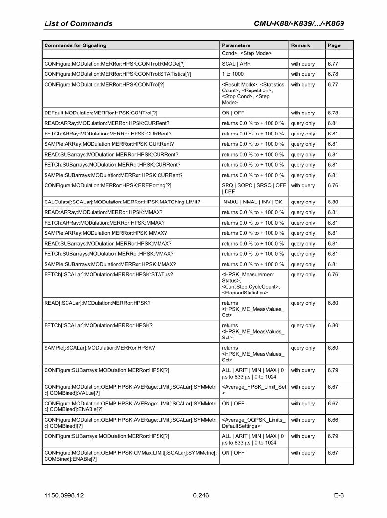
List of Commands CMU-K88/-K839/.../-K869
1150.3998.12 6.246 E-3
Commands for Signaling Parameters Remark Page Cond>, <Step Mode>
CONFigure:MODulation:MERRor:HPSK:CONTrol:RMODe[?] SCAL | ARR with query 6.77
CONFigure:MODulation:MERRor:HPSK:CONTrol:STATistics[?] 1 to 1000 with query 6.78
CONFigure:MODulation:MERRor:HPSK:CONTrol[?] <Result Mode>, <Statistics Count>, <Repetition>, <Stop Cond>, <Step Mode>
with query 6.77
DEFault:MODulation:MERRor:HPSK:CONTrol[?] ON | OFF with query 6.78
READ:ARRay:MODulation:MERRor:HPSK:CURRent? returns 0.0 % to + 100.0 % query only 6.81
FETCh:ARRay:MODulation:MERRor:HPSK:CURRent? returns 0.0 % to + 100.0 % query only 6.81
SAMPle:ARRay:MODulation:MERRor:HPSK:CURRent? returns 0.0 % to + 100.0 % query only 6.81
READ:SUBarrays:MODulation:MERRor:HPSK:CURRent? returns 0.0 % to + 100.0 % query only 6.81
FETCh:SUBarrays:MODulation:MERRor:HPSK:CURRent? returns 0.0 % to + 100.0 % query only 6.81
SAMPle:SUBarrays:MODulation:MERRor:HPSK:CURRent? returns 0.0 % to + 100.0 % query only 6.81
CONFigure:MODulation:MERRor:HPSK:EREPorting[?] SRQ | SOPC | SRSQ | OFF | DEF
with query 6.76
CALCulate[:SCALar]:MODulation:MERRor:HPSK:MATChing:LIMit? NMAU | NMAL | INV | OK query only 6.80
READ:ARRay:MODulation:MERRor:HPSK:MMAX? returns 0.0 % to + 100.0 % query only 6.81
FETCh:ARRay:MODulation:MERRor:HPSK:MMAX? returns 0.0 % to + 100.0 % query only 6.81
SAMPle:ARRay:MODulation:MERRor:HPSK:MMAX? returns 0.0 % to + 100.0 % query only 6.81
READ:SUBarrays:MODulation:MERRor:HPSK:MMAX? returns 0.0 % to + 100.0 % query only 6.81
FETCh:SUBarrays:MODulation:MERRor:HPSK:MMAX? returns 0.0 % to + 100.0 % query only 6.81
SAMPle:SUBarrays:MODulation:MERRor:HPSK:MMAX? returns 0.0 % to + 100.0 % query only 6.81
FETCh[:SCALar]:MODulation:MERRor:HPSK:STATus? <HPSK_Measurement Status>, <Curr.Step.CycleCount>, <ElapsedStatistics>
query only 6.76
READ[:SCALar]:MODulation:MERRor:HPSK? returns <HPSK_ME_MeasValues_Set>
query only 6.80
FETCh[:SCALar]:MODulation:MERRor:HPSK? returns <HPSK_ME_MeasValues_Set>
query only 6.80
SAMPle[:SCALar]:MODulation:MERRor:HPSK? returns <HPSK_ME_MeasValues_Set>
query only 6.80
CONFigure:SUBarrays:MODulation:MERRor:HPSK[?] ALL | ARIT | MIN | MAX | 0 µs to 833 µs | 0 to 1024
with query 6.79
CONFigure:MODulation:OEMP:HPSK:AVERage:LIMit[:SCALar]:SYMMetric[:COMBined]:VALue[?]
<Average_HPSK_Limit_Set>
with query 6.67
CONFigure:MODulation:OEMP:HPSK:AVERage:LIMit[:SCALar]:SYMMetric[:COMBined]:ENABle[?]
ON | OFF with query 6.67
CONFigure:MODulation:OEMP:HPSK:AVERage:LIMit[:SCALar]:SYMMetric[:COMBined][?]
<Average_OQPSK_Limits_DefaultSettings>
with query 6.66
CONFigure:SUBarrays:MODulation:MERRor:HPSK[?] ALL | ARIT | MIN | MAX | 0 µs to 833 µs | 0 to 1024
with query 6.79
CONFigure:MODulation:OEMP:HPSK:CMMax:LIMit[:SCALar]:SYMMetric[:COMBined]:ENABle[?]
ON | OFF with query 6.67

CMU-K88/-K839/.../-K869 List of Commands
1150.3998.12 6.247 E-3
Commands for Signaling Parameters Remark Page
CONFigure:MODulation:OEMP:HPSK:CMMax:LIMit[:SCALar]:SYMMetric[:COMBined]:VALue[?]
<CMMAX_OQPSK_Limits_DefaultSettings>
with query 6.66
CONFigure:MODulation:OEMP:HPSK:CMMax:LIMit[:SCALar]:SYMMetric[:COMBined][?]
<CMMAX_OQPSK_Limits_DefaultSettings>
with query 6.65
DEFault:MODulation:OEMP:HPSK:LIMit[?] ON | OFF with query 6.68
INITiate:MODulation:OVERview:HPSK RUN no query 6.61
ABORt:MODulation:OVERview:HPSK OFF no query 6.61
CONTinue:MODulation:OVERview:HPSK RUN no query 6.61
STOP:MODulation:OVERview:HPSK STOP no query 6.61
CONFigure:MODulation:OVERview:HPSK:CONTrol:REPetition[?] <Repetition>, <Stop Cond>, <Step Mode>
with query 6.64
CONFigure:MODulation:OVERview:HPSK:CONTrol:STATistics[?] 1 to 1000 with query 6.64
DEFault:MODulation:OVERview:HPSK:CONTrol[?] ON | OFF with query 6.63
CONFigure:MODulation:OVERview:HPSK:CONTrol[?] <Statistic Count>, <Repetition>, <Stop Cond>, <Step Mode>
with query 6.63
CONFigure:MODulation:OVERview:HPSK:EREPorting[?] SRQ | SOPC | SRSQ | OFF | DEF
with query 6.62
CALCulate[:SCALar]:MODulation:OVERview:HPSK:MATChing:LIMit? NMAU | NMAL | INV | OK query only 6.69
FETCh[:SCALar]:MODulation:OVERview:HPSK:STATus? <HPSK_Measurement Status>, <Curr.Step.CycleCount>, <ElapsedStatistics>
query only 6.62
READ[:SCALar]:MODulation:OVERview:HPSK? <OvwHPSK_MeasValues_Set>
query only 6.68
FETCh[:SCALar]:MODulation:OVERview:HPSK? <OvwHPSK_MeasValues_Set>
query only 6.68
SAMPle[:SCALar]:MODulation:OVERview:HPSK? <OvwHPSK_MeasValues_Set>
query only 6.68
Modulation Phase Error
INITiate:MODulation:PERRor:HPSK RUN no query 6.82
ABORt:MODulation:PERRor:HPSK OFF no query 6.82
STOP:MODulation:PERRor:HPSK STOP no query 6.82
CONTinue:MODulation:PERRor:HPSK RUN no query 6.82
READ:ARRay:MODulation:PERRor:HPSK:AVERage? –100.0 deg to + 100.0 deg query only 6.87
FETCh:ARRay:MODulation:PERRor:HPSK:AVERage? –100.0 deg to + 100.0 deg query only 6.87
SAMPle:ARRay:MODulation:PERRor:HPSK:AVERage? –100.0 deg to + 100.0 deg query only 6.87
READ:SUBarrays:MODulation:PERRor:HPSK:AVERage? –100.0 deg to + 100.0 deg query only 6.87
FETCh:SUBarrays:MODulation:PERRor:HPSK:AVERage? –100.0 deg to + 100.0 deg query only 6.87
SAMPle:SUBarrays:MODulation:PERRor:HPSK:AVERage? –100.0 deg to + 100.0 deg query only 6.87
CONFigure:MODulation:PERRor:HPSK:CONTrol:REPetition[?] <Repetition>, <Stop Cond>, <Step Mode>
with query 6.84
CONFigure:MODulation:PERRor:HPSK:CONTrol:RMODe[?] SCAL | ARR with query 6.84
CONFigure:MODulation:PERRor:HPSK:CONTrol:STATistics[?] 1 to 1000 with query 6.83
CONFigure:MODulation:PERRor:HPSK:CONTrol[?] <Result Mode>, <Statistics Count>, <Repetition>, <Stop Cond>, <Step Mode>
with query 6.83

List of Commands CMU-K88/-K839/.../-K869
1150.3998.12 6.248 E-3
Commands for Signaling Parameters Remark Page
DEFault:MODulation:PERRor:HPSK:CONTrol[?] ON | OFF with query 6.84
READ:ARRay:MODulation:PERRor:HPSK:CURRent? –100.0 deg to + 100.0 deg query only 6.87
FETCh:ARRay:MODulation:PERRor:HPSK:CURRent? –100.0 deg to + 100.0 deg query only 6.87
SAMPle:ARRay:MODulation:PERRor:HPSK:CURRent? –100.0 deg to + 100.0 deg query only 6.87
READ:SUBarrays:MODulation:PERRor:HPSK:CURRent? –100.0 deg to + 100.0 deg query only 6.87
FETCh:SUBarrays:MODulation:PERRor:HPSK:CURRent? –100.0 deg to + 100.0 deg query only 6.87
SAMPle:SUBarrays:MODulation:PERRor:HPSK:CURRent? –100.0 deg to + 100.0 deg query only 6.87
CONFigure:MODulation:PERRor:HPSK:EREPorting[?] SRQ | SOPC | SRSQ | OFF | DEF
with query 6.82
CALCulate[:SCALar]:MODulation:PERRor:HPSK:MATChing:LIMit? NMAU | NMAL | INV | OK query only 6.86
READ:ARRay:MODulation:PERRor:HPSK:MMAX? –100.0 deg to + 100.0 deg query only 6.87
FETCh:ARRay:MODulation:PERRor:HPSK:MMAX? –100.0 deg to + 100.0 deg query only 6.87
SAMPle:ARRay:MODulation:PERRor:HPSK:MMAX? –100.0 deg to + 100.0 deg query only 6.87
READ:SUBarrays:MODulation:PERRor:HPSK:MMAX? –100.0 deg to + 100.0 deg query only 6.87
FETCh:SUBarrays:MODulation:PERRor:HPSK:MMAX? –100.0 deg to + 100.0 deg query only 6.87
SAMPle:SUBarrays:MODulation:PERRor:HPSK:MMAX? –100.0 deg to + 100.0 deg query only 6.87
FETCh[:SCALar]:MODulation:PERRor:HPSK:STATus? <HPSK_Measurement Status>, <Curr.Step.CycleCount>, <ElapsedStatistics>
query only 6.82
READ[:SCALar]:MODulation:PERRor:HPSK? returns <HPSK_EVM_MeasValues_Set>
query only 6.86
FETCh[:SCALar]:MODulation:PERRor:HPSK? returns <HPSK_EVM_MeasValues_Set>
query only 6.86
SAMPle[:SCALar]:MODulation:PERRor:HPSK? returns <HPSK_EVM_MeasValues_Set>
query only 6.86
CONFigure:SUBarrays:MODulation:PERRor:HPSK[?] ALL | ARIT | MIN | MAX | 0 µs to 833 µs | 0 to 1024
with query 6.85
Network
CONFigure:NETWork:APRobes:ACCess:OFFSet? <34 char hex> query only 6.203
CONFigure:NETWork:APRobes:ACDuration[?] 16 | 32 | 64 | 128 with query 6.202
CONFigure:NETWork:APRobes:ADJust? 0 | 16 | 32 | 48 | 64 | 80 | 96 | 112
query only 6.203
CONFigure:NETWork:APRobes:IADjust[?] -16 dB to 15 dB with query 6.200
CONFigure:NETWork:APRobes:MODE[?] ACKN | IGN | DEF with query 6.200
CONFigure:NETWork:APRobes:OLADjust[?] -100 dB to 66 dB with query 6.201
CONFigure:NETWork:APRobes:PINCrement[?] 0.0 dB to 7.5 dB with query 6.201
CONFigure:NETWork:APRobes:PLENgth:SLOTs[?] 4 | 16 with query 6.202
CONFigure:NETWork:APRobes:PLENgth[?] 1 to 15 with query 6.202
CONFigure:NETWork:APRobes:PPSQuence[?] 1 to 15 with query 6.201
CONFigure:NETWork:APRobes:PSTRength:CMAX? +0.0 dB to +5.0 dB query only 6.204
CONFigure:NETWork:APRobes:PSTRength:CMIN? –5.0 dB to +0.0 dB query only 6.204
CONFigure:NETWork:APRobes:PSTRength:NOMinal? –4.0 dB to +3.0 dB query only 6.203

CMU-K88/-K839/.../-K869 List of Commands
1150.3998.12 6.249 E-3
Commands for Signaling Parameters Remark Page
CONFigure:NETWork:APRobes:SACCess:RATe:MAX[?] R9K | R19K | R38K with query 6.203
CONFigure:NETWork:RELease[?] 0 | A | DEF with query 6.199
CONFigure:NETWork:STANdard[?] USC | KCEL | NAPC | TACS | JTAC | KPCS | N45T | IM2K | NA7C | B18M | NA9C | NA8S | PA4M | PA8M | IEXT | USPC | AWS
with query 6.199
CONFigure:NETWork:SYSTem:SID[?] 0 to 32767 with query 6.200
DEFault:NETWork[?] ON | OFF with query 6.198
Narrow Band Power
INITiate:NPOWer RUN no query 6.56
ABORt:NPOWer OFF no query 6.56
STOP:NPOWer STOP no query 6.56
CONTinue:NPOWer RUN no query 6.56
CONFigure:NPOWer:CONTrol:REPetition[?] <Repetition>, <Stop Condition>, <Step Mode>
with query 6.59
CONFigure:NPOWer:CONTrol:STATistics[?] 1 to 1000 with query 6.58
CONFigure:NPOWer:CONTrol[?] <Statistics>, <Repetition>, <Stop Condition>, <Step Mode>
with query 6.58
CONFigure:NPOWer:EREPorting[?] SRQ | SOPC | SRSQ | OFF | DEF
with query 6.56
FETCh[:SCALar]:NPOWer:STATus? <MeasurementStatus>, <Curr.Step.CycleCount>, <ElapsedStatistics>
query only 6.57
READ[:SCALar]:NPOWer? –137 dBm to +53 dBm query only 6.60
FETCh[:SCALar]:NPOWer? –137 dBm to +53 dBm query only 6.60
SAMPle[:SCALar]:NPOWer? –137 dBm to +53 dBm query only 6.60
Ping Measurements
INITiate:PING – no query 6.153
ABORt:PING – no query 6.153
STOP:PING – no query 6.153
CONTinue:PING – no query 6.153
CONFigure:PING:CONTrol:ATIP[?] ON | OFF with query 6.155
CONFigure:PING:CONTrol:IPADdress <Addr_1>, <Addr_2>, <Addr_3>, <Addr_4>
with query 6.155
CONFigure:PING:CONTrol:PCOunt[?] 1 to 255 with query 6.154
CONFigure:PING:CONTrol:PSIZe[?] 1 byte to 1520 bytes with query 6.155
CONFigure:PING:CONTrol:REPetition[?] <Repetition>,<StopCond>,<Stepmode>
with query 6.154
CONFigure:PING:CONTrol:RINTerval[?] 1 s to 100 s with query 6.155
CONFigure:PING:CONTrol:TOUT[?] 0.001 s to 10 s with query 6.155
DEFault:PING:CONTrol[?] ON | OFF with query 6.154
CONFigure:PING:EREPorting[?] SRQ | SOPC | SRSQ | OFF with query 6.153

List of Commands CMU-K88/-K839/.../-K869
1150.3998.12 6.250 E-3
Commands for Signaling Parameters Remark Page
FETCh[:SCALar]:PING:STATus OFF | RUN | STOP | ERR | STEP | RDY, 1 to 10000 | NONE, 1 to 1000 | NONE
with query 6.153
READ[:SCALar]:PING? <IP address>, <packet size>, <reply time>
query only 6.157
FETCh[:SCALar]:PING? <IP address>, <packet size>, <reply time>
query only 6.157
SAMPle[:SCALar]:PING? <IP address>, <packet size>, <reply time>
query only 6.157
RF Analyzer
DEFault:RFANalyzer[?] ON | OFF with query 6.204
[SENSe]:RFANalyzer:CCFilter:ACK[?] ON | OFF| DCARe with query 6.206
[SENSe]:RFANalyzer:CCFilter:ADSC[?] OFF | ACK | DSC | DCARe with query 6.206
[SENSe]:RFANalyzer:CCFilter:APILot[?] ON | OFF| DCARe with query 6.206
[SENSe]:RFANalyzer:CCFilter:DATA[?] ON | OFF| DCARe with query 6.206
[SENSe]:RFANalyzer:CCFilter:DRC[?] ON | OFF| DCARe with query 6.206
[SENSe]:RFANalyzer:CCFilter:HSLot[?] BOTH | 1 | 2 with query 6.207
[SENSe]:RFANalyzer:DCHannel:MTYPe:MODE[?] AUTO | B4 | Q4 | Q2 | Q4Q2 | E4E2
with query 6.208
[SENSe]:RFANalyzer:DCHannel:MTYPe? B4 | Q4 | Q2 | Q4Q2 | E4E2 query only 6.208
[SENSe]:RFANalyzer:Selectivity[?] WIDE | IFL | DEF with query 6.214
[SENSe]:RFANalyzer:Subtype[?] 0 … 2 with query 6.205
RLP Statistics
[SENSe:][SCALar:]:RLPStatistic? <return values> query only 6.156
Receiver Quality
INITiate:RXQuality:CCPer RUN no query 6.135
ABORt:RXQuality:CCPer OFF no query 6.135
STOP:RXQuality:CCPer STOP no query 6.135
CONFigure:RXQuality:CCPer:CONTrol:MCCCycles[?] 1 to 1000 with query 6.136
CONFigure:RXQuality:CCPer:CONTrol:REPetition[?] <Repetition>, <Stop Condition>
with query 6.136
CONFigure:RXQuality:CCPer:EREPorting[?] SRQ | SOPC | SRSQ | OFF with query 6.135
CONFigure:RXQuality:CCPer:LIMit:CLEVel[?] 0 to 100% with query 6.137
CONFigure:RXQuality:CCPer:LIMit:MPER[?] 0 to 100% with query 6.136
CALCulate:RXQuality:CCPer:MATChing:LIMit? NMAU | NMAL | INV | OK query only 6.137
FETCh[:SCALar]:RXQuality:CCPer:STATus? <MeasurementStatus>, <Curr.Step.CycleCount>, <ElapsedStatistics>
query only 6.135
READ[:SCALar]:RXQuality:CCPer? –30.0 dBm to +30.0 dBm query only 6.137
FETCh[:SCALar]:RXQuality:CCPer? –30.0 dBm to +30.0 dBm query only 6.137
SAMPle[:SCALar]:RXQuality:CCPer? –30.0 dBm to +30.0 dBm query only 6.137
DEFault:RXQuality:CONTrol[?] ON | OFF with query 6.133
INITiate:RXQuality:FLPer RUN no query 6.138
ABORt:RXQuality:FLPer OFF no query 6.138
STOP:RXQuality:FLPer STOP no query 6.138

CMU-K88/-K839/.../-K869 List of Commands
1150.3998.12 6.251 E-3
Commands for Signaling Parameters Remark Page
CONFigure:RXQuality:FLPer:CONTrol:MTPSent?] 1 to 100000 with query 6.139
CONFigure:RXQuality:FLPer:CONTrol:REPetition[?] <Repetition>, <Stop Condition>
with query 6.139
CONFigure:RXQuality:FLPer:EREPorting[?] SRQ | SOPC | SRSQ | OFF with query 6.138
CONFigure:RXQuality:FLPer:LIMit:CLEVel[?] 0 to 100% with query 6.140
CONFigure:RXQuality:FLPer:LIMit:MPER[?] 0 to 100% with query 6.139
CALCulate:RXQuality:FLPer:MATChing:LIMit? NMAU | NMAL | INV | OK query only 6.140
FETCh[:SCALar]:RXQuality:FLPer:STATus? <MeasurementStatus>, <Curr.Step.CycleCount>, <ElapsedStatistics>
query only 6.138
SAMPle[:SCALar]:RXQuality:FLPer? – query only 6.140
READ[:SCALar]:RXQuality:FLPer? – query only 6.140
FETCh[:SCALar]:RXQuality:FLPer? – query only 6.140
INITiate:RXQuality:FLPFormance RUN no query 6.144
ABORt:RXQuality:FLPFormance OFF no query 6.144
STOP:RXQuality:FLPFormance STOP no query 6.144
CONFigure:RXQuality:FLPFormance:CONTrol:MFrames?] 1 to 10000 with query 6.145
CONFigure:RXQuality:FLPFormance:CONTrol:REPetition[?] <Repetition> with query 6.145
CONFigure:RXQuality:FLPFormance:EREPorting[?] SRQ | SOPC | SRSQ | OFF with query 6.144
FETCh[:SCALar]:RXQuality:FLPFormance:STATus? <MeasurementStatus>, <Curr.Step.CycleCount>, <ElapsedStatistics>
query only 6.144
READ[:SCALar]:RXQuality:FLPFormance? <MAC Packets Received>, <Physical Pkt. Slots>, <Throughput vs. TestTime>, <Throughput vs.transmitted slots>, <Test Time>
query only 6.145
FETCh[:SCALar]:RXQuality:FLPFormance? <MAC Packets Received>, <Physical Pkt. Slots>, <Throughput vs. TestTime>, <Throughput vs.transmitted slots>, <Test Time>
query only 6.145
SAMPle[:SCALar]:RXQuality:FLPFormance? <MAC Packets Received>, <Physical Pkt. Slots>, <Throughput vs. TestTime>, <Throughput vs.transmitted slots>, <Test Time>
query only 6.145
DEFault:RXQuality:LIMit[?] ON | OFF with query 6.134
INITiate:RXQuality:RLPer RUN no query 6.148
ABORt:RXQuality:RLPer OFF no query 6.148
STOP:RXQuality:RLPer STOP no query 6.148
CONFigure:RXQuality:RLPer:CONTrol:MPReiceived[?] 1 to 1000 with query 6.149
CONFigure:RXQuality:RLPer:CONTrol:REPetition[?] <Repetition>, <Stop Condition>
with query 6.149
CALCulate:RXQuality:RLPer:DPLProtocol:MATChing:LIMit? NMAU | NMAL | INV | OK query only 6.151

List of Commands CMU-K88/-K839/.../-K869
1150.3998.12 6.252 E-3
Commands for Signaling Parameters Remark Page
READ[:SCALar]:RXQuality:RLPer:DPLProtocol? <MAC Pkts Transmitted>, <Rev. Link PER MAC Pkts Received>, <Rev Link PER Conf. Level>, <Rev. Link PER>, <Term. Target PER Target MAC Pkts Rec.>, <Term. Target PER Conf. Level>, <Term. Target PER>
query only 6.150
FETCh[:SCALar]:RXQuality:RLPer:DPLProtocol? <MAC Pkts Transmitted>, <Rev. Link PER MAC Pkts Received>, <Rev Link PER Conf. Level>, <Rev. Link PER>, <Term. Target PER Target MAC Pkts Rec.>, <Term. Target PER Conf. Level>, <Term. Target PER>
query only 6.150
SAMPle[:SCALar]:RXQuality:RLPer:DPLProtocol? <MAC Pkts Transmitted>, <Rev. Link PER MAC Pkts Received>, <Rev Link PER Conf. Level>, <Rev. Link PER>, <Term. Target PER Target MAC Pkts Rec.>, <Term. Target PER Conf. Level>, <Term. Target PER>
query only 6.150
CONFigure:RXQuality:RLPer:EREPorting[?] SRQ | SOPC | SRSQ | OFF with query 6.148
CONFigure:RXQuality:RLPer:LIMit:CLEVel[?] 0 to 100% with query 6.150
CONFigure:RXQuality:RLPer:LIMit:MPER[?] 0 to 100% with query 6.149
CALCulate:RXQuality:RLPer:S2PL:MATChing:LIMit? NMAU | NMAL | INV | OK query only 6.152
READ[:SCALar]:RXQuality:RLPer:S2PL? <MAC Pkts Transmitted>, <Rev. Link PER MAC Pkts Received>, <Rev Link PER Conf. Level>, <Rev. Link PER>, <Term. Target PER Target MAC Pkts Rec.>, <Term. Target PER Conf. Level>, <Term. Target PER>
query only 6.151
FETCh[:SCALar]:RXQuality:RLPer:S2PL? <MAC Pkts Transmitted>, <Rev. Link PER MAC Pkts Received>, <Rev Link PER Conf. Level>, <Rev. Link PER>, <Term. Target PER Target MAC Pkts Rec.>, <Term. Target PER Conf. Level>, <Term. Target PER>
query only 6.151
SAMPle[:SCALar]:RXQuality:RLPer:S2PL? <MAC Pkts Transmitted>, <Rev. Link PER MAC Pkts Received>, <Rev Link PER Conf. Level>, <Rev. Link PER>, <Term. Target PER Target MAC Pkts Rec.>, <Term. Target PER Conf. Level>, <Term. Target PER>
query only 6.151
FETCh[:SCALar]:RXQuality:RLPer:STATus? <MeasurementStatus>, <Curr.Step.CycleCount>, <ElapsedStatistics>
query only 6.148
INITiate:RXQuality:RLPFormance RUN no query 6.145

CMU-K88/-K839/.../-K869 List of Commands
1150.3998.12 6.253 E-3
Commands for Signaling Parameters Remark Page
ABORt:RXQuality:RLPFormance OFF no query 6.145
STOP:RXQuality:RLPFormance STOP no query 6.145
CONFigure:RXQuality:RLPFormance:CONTrol:MFrames?] 1 to 10000 with query 6.147
CONFigure:RXQuality:RLPFormance:CONTrol:REPetition[?] <Repetition> with query 6.146
READ[:SCALar]:RXQuality:RLPFormance:DPLProtocol? <MAC Packets Received>, <Throughput vs. TestTime>, <Test Time>
query only 6.147
FETCh[:SCALar]:RXQuality:RLPFormance:DPLProtocol? <MAC Packets Received>, <Throughput vs. TestTime>, <Test Time>
query only 6.147
SAMPle[:SCALar]:RXQuality:RLPFormance:DPLProtocol? <MAC Packets Received>, <Throughput vs. TestTime>, <Test Time>
query only 6.147
CONFigure:RXQuality:RLPFormance:EREPorting[?] SRQ | SOPC | SRSQ | OFF with query 6.146
READ[:SCALar]:RXQuality:RLPFormance:S2PL? <MAC Packets Received>, <Throughput vs. TestTime>, <Test Time>
query only 6.147
FETCh[:SCALar]:RXQuality:RLPFormance:S2PL? <MAC Packets Received>, <Throughput vs. TestTime>, <Test Time>
query only 6.147
SAMPle[:SCALar]:RXQuality:RLPFormance:S2PL? <MAC Packets Received>, <Throughput vs. TestTime>, <Test Time>
query only 6.147
FETCh[:SCALar]:RXQuality:RLPFormance:STATus? <MeasurementStatus>, <Curr.Step.CycleCount>, <ElapsedStatistics>
query only 6.146
INITiate:RXQuality:RLQuality RUN no query 6.141
ABORt:RXQuality:RLQuality OFF no query 6.141
STOP:RXQuality:RLQuality STOP no query 6.141
CONFigure:RXQuality:RLQuality:CONTrol:MLPSent?] 1 to 100000 with query 6.142
CONFigure:RXQuality:RLQuality:CONTrol:REPetition[?] <Repetition>, <Stop Condition>
with query 6.142
CONFigure:RXQuality:RLQuality:EREPorting[?] SRQ | SOPC | SRSQ | OFF with query 6.141
CONFigure:RXQuality:RLQuality:LIMit:CLEVel[?] 0 to 100% with query 6.143
CONFigure:RXQuality:RLQuality:LIMit:MPER[?] 0 to 100% with query 6.142
CALCulate:RXQuality:RLQuality:MATChing:LIMit? NMAU | NMAL | INV | OK query only 6.143
FETCh[:SCALar]:RXQuality:RLQuality:STATus? <MeasurementStatus>, <Curr.Step.CycleCount>, <ElapsedStatistics>
query only 6.141
SAMPle[:SCALar]:RXQuality:RLQuality? – query only 6.143
READ[:SCALar]:RXQuality:RLQuality? – query only 6.143
FETCh[:SCALar]:RXQuality:RLQuality? – query only 6.143
[SENSe:][SCALar:]:RXQuality:SOVerview? – query only 6.134
Standby Power / Access Probe Power
INITiate:SAPPower RUN no query 6.60
ABORt:SAPPower OFF no query 6.60
STOP:SAPPower STOP no query 6.60
CONTinue:SAPPower RUN no query 6.60

List of Commands CMU-K88/-K839/.../-K869
1150.3998.12 6.254 E-3
Commands for Signaling Parameters Remark Page
CONFigure:SAPPower:EREPorting[?] SRQ | SOPC | SRSQ | OFF with query 6.60
FETCh[:SCALar]:SAPPower:STATus? OFF | RUN | STOP | ERR | STEP | RDY
query only 6.61
READ[:SCALar]:SAPPower? <Standby Power>, <Access Probe Power>
query only 6.61
FETCh[:SCALar]:SAPPower? <Standby Power>, <Access Probe Power>
query only 6.61
SAMPle[:SCALar]:SAPPower? <Standby Power>, <Access Probe Power>
query only 6.61
Signaling State Control
PROCedure:SIGNalling:ACTion SOFF | SON | CSESsion | RNEGotiate | CTMobile | CREL | HANDoff
no query 6.158
[SENSe]:SIGNalling:STATe:PPP? OFF | DORM | CONN query only 6.159
[SENSe:]SIGNalling:STATe? SOFF | SON | NEG | SOP | CEST | CPEN | FPEN
query only 6.159
ACP Spectrum
INITiate:SPECtrum:ACP RUN no query 6.92
ABORt:SPECtrum:ACP OFF no query 6.92
STOP:SPECtrum:ACP STOP no query 6.92
CONTinue:SPECtrum:ACP RUN no query 6.92
CONFigure:SPECtrum:ACP:CONTrol:FOFFset:ACP<nr>[?] 0 to 2 MHz | OFF | ON with query 6.95
CONFigure:SPECtrum:ACP:CONTrol:REPetition[?] <Repetition>, <Stop Cond>, <Step Mode>
with query 6.94
CONFigure:SPECtrum:ACP:CONTrol:STATistics[?] 1 to 1000 with query 6.93
CONFigure:SPECtrum:ACP:CONTrol[?] <StatisticCount>, <Repetition>, <Stop Cond>, <Step Mode>
with query 6.93
DEFault:SPECtrum:ACP:CONTrol[?] ON | OFF with query 6.94
CONFigure:SPECtrum:ACP:EREPorting[?] SRQ | SOPC | SRSQ | DEF | OFF
with query 6.92
CONFigure:SPECtrum:ACP:LIMit:ACP1[?] –80.0 to +10.0 | ON | OFF | MIN | MAX | DEF
with query 6.97
XTND:SPECtrum:ACP:LIMit[?] ON | OFF | DEF with query 6.59
DEFault:SPECtrum:ACP:LIMit[?] ON | OFF with query 6.97
CALCulate[:SCALar]:SPECtrum:ACP:MATChing:LIMit? NMAU | NMAL | INV | OK query only 6.99
XTND:SPECtrum:ACP:STATistics[?] ON | OFF | DEF with query 6.97
FETCh[:SCALar]:SPECtrum:ACP:STATus? <MeasurementStatus>, <Curr.Step.CycleCount>, <ElapsedStatistics>
query only 6.92
READ[:SCALar]:SPECtrum:ACP? –80.0 dB to 0.0 dB query only 6.98
FETCh[:SCALar]:SPECtrum:ACP? –80.0 dB to 0.0 dB query only 6.98
SAMPle[:SCALar]:SPECtrum:ACP? –80.0 dB to 0.0 dB query only 6.98
Trigger
TRIGger:OUTPut:PIN<nr>:SIGNal[?] NONE | PP2S | SFR | PFR | SNCF | ETR | DEF
with query 6.213
TRIGger[:SEQuence]:SLOPe[?] NEG | POS | DEF with query 6.213

CMU-K88/-K839/.../-K869 List of Commands
1150.3998.12 6.255 E-3
Commands for Signaling Parameters Remark Page
TRIGger[:SEQuence]:SOURce[?] INT | EXT | FRUN | RFP | IFP | DEF
with query 6.213
TRIGger[:SEQuence]:THReshold:IFPower[?] -47.0 dB to 0 dB with query 6.212
TRIGger[:SEQuence]:THReshold:RFPower[?] LOW | MED | HIGH with query 6.212
DEFault:TRIGger[:SEQuence][?] ON | OFF with query 6.211
Update Period
CONFigure:UPERiod[?] 0.2 s to 2.0 s with query 6.133
CONFigure:UPERiod[?] 0.2 s to 2.0 s with query 6.152
Wide Band Power
INITiate:WPOWer RUN no query 6.215
ABORt:WPOWer OFF no query 6.215
STOP:WPOWer STOP no query 6.215
CONTinue:WPOWer RUN no query 6.215
CONFigure:WPOWer:CONTrol:REPetition[?] <Repetition>,<StopCond>,<Stepmode>
with query 6.216
CONFigure:WPOWer:EREPorting[?] SRQ | SOPC | SRSQ | OFF
with query 6.215
FETCh:WPOWer:STATus? returns <Measurement Status> and <Curr. Step Cycle Count>
query only 6.216
READ[:SCALar]:WPOWer? –30.0 dBm to +30.0 dBm query only 6.217
FETCh[:SCALar]:WPOWer? –30.0 dBm to +30.0 dBm query only 6.217
SAMPle[:SCALar]:WPOWer? –30.0 dBm to +30.0 dBm query only 6.217
Table 6-3 Remote-control commands, alphabetical list (both Signaling and Non-Signaling)
Command (both Signaling and Non-Signaling) PageABORt:CDPower:CDPW 6.100ABORt:CDPower:CHPW 6.120ABORt:CDPower:PCDep 6.111ABORt:IQACcess 6.35ABORt:MODulation:EVMagnitude:HPSK 6.69ABORt:MODulation:IQANalyzer:HPSK 6.88ABORt:MODulation:MERRor:HPSK 6.76ABORt:MODulation:MQUality:HPSK 6.47ABORt:MODulation:OVERview:HPSK 6.61ABORt:MODulation:PERRor:HPSK 6.82ABORt:NPOWer 6.56ABORt:PING 6.153ABORt:RFGenerator 6.15ABORt:RFGenerator:AT<nr>:MAC:INDex 6.22ABORt:RFGenerator:AT<nr>:PSTReam 6.24ABORt:RFGenerator:MAC:INDex 6.22ABORt:RFGenerator:PSTReam 6.24ABORt:RFGenerator:SNCMessage 6.20ABORt:RXQuality:CCPer 6.135ABORt:RXQuality:FLPer 6.138ABORt:RXQuality:FLPFormance 6.144

List of Commands CMU-K88/-K839/.../-K869
1150.3998.12 6.256 E-3
Command (both Signaling and Non-Signaling) PageABORt:RXQuality:RLPer 6.148ABORt:RXQuality:RLPFormance 6.145ABORt:RXQuality:RLQuality 6.141ABORt:SAPPower 6.60ABORt:SPECtrum:ACP 6.92ABORt:WPOWer 6.38ABORt:WPOWer 6.215CALCulate:ARRay:CDPower:CDPW:AVERage[:RESult]:MATChing:LIMit? 6.110CALCulate:ARRay:CDPower:CDPW:CURRent[:RESult]:MATChing:LIMit? 6.109CALCulate:ARRay:CDPower:CDPW:ISIGnal:AVERage[:RESult]:MATChing:LIMit?(*) 6.110CALCulate:ARRay:CDPower:CDPW:ISIGnal:CURRent[:RESult]:MATChing:LIMit?(*) 6.109CALCulate:ARRay:CDPower:CDPW:ISIGnal:MAXimum[:RESult]:MATChing:LIMit?(*) 6.110CALCulate:ARRay:CDPower:CDPW:MAXimum[:RESult]:MATChing:LIMit? 6.110CALCulate:ARRay:CDPower:CDPW:QSIGnal:AVERage[:RESult]:MATChing:LIMit?(*) 6.110CALCulate:ARRay:CDPower:CDPW:QSIGnal:CURRent[:RESult]:MATChing:LIMit?(*) 6.109CALCulate:ARRay:CDPower:CDPW:QSIGnal:MAXimum[:RESult]:MATChing:LIMit?(*) 6.110CALCulate:ARRay:CDPower:CHPW:AVERage[:RESult]:MATChing:LIMit? 6.131CALCulate:ARRay:CDPower:CHPW:CURRent[:RESult]:MATChing:LIMit? 6.130CALCulate:ARRay:CDPower:CHPW:ISIGnal:AVERage[:RESult]:MATChing:LIMit?(*) 6.131CALCulate:ARRay:CDPower:CHPW:ISIGnal:CURRent[:RESult]:MATChing:LIMit?(*) 6.130CALCulate:ARRay:CDPower:CHPW:ISIGnal:MAXimum[:RESult]:MATChing:LIMit?(*) 6.132CALCulate:ARRay:CDPower:CHPW:MAXimum[:RESult]:MATChing:LIMit? 6.132CALCulate:ARRay:CDPower:CHPW:QSIGnal:AVERage[:RESult]:MATChing:LIMit?(*) 6.131CALCulate:ARRay:CDPower:CHPW:QSIGnal:CURRent[:RESult]:MATChing:LIMit?(*) 6.130CALCulate:ARRay:CDPower:CHPW:QSIGnal:MAXimum[:RESult]:MATChing:LIMit?(*) 6.132CALCulate:ARRay:CDPower:PCDep:AVERage[:RESult]:MATChing:LIMit? 6.120CALCulate:ARRay:CDPower:PCDep:CURRent[:RESult]:MATChing:LIMit? 6.119CALCulate:ARRay:CDPower:PCDep:ISIGnal:AVERage[:RESult]:MATChing:LIMit?(*) 6.120CALCulate:ARRay:CDPower:PCDep:ISIGnal:CURRent[:RESult]:MATChing:LIMit?(*) 6.119CALCulate:ARRay:CDPower:PCDep:ISIGnal:MAXimum[:RESult]:MATChing:LIMit?(*) 6.120CALCulate:ARRay:CDPower:PCDep:MAXimum[:RESult]:MATChing:LIMit? 6.120CALCulate:ARRay:CDPower:PCDep:QSIGnal:AVERage[:RESult]:MATChing:LIMit?(*) 6.120CALCulate:ARRay:CDPower:PCDep:QSIGnal:CURRent[:RESult]:MATChing:LIMit?(*) 6.119CALCulate:ARRay:CDPower:PCDep:QSIGnal:MAXimum[:RESult]:MATChing:LIMit?(*) 6.120CALCulate:RXQuality:CCPer:MATChing:LIMit? 6.137CALCulate:RXQuality:FLPer:MATChing:LIMit? 6.140CALCulate:RXQuality:RLPer:DPLProtocol:MATChing:LIMit? 6.151CALCulate:RXQuality:RLPer:S2PL:MATChing:LIMit? 6.152CALCulate:RXQuality:RLQuality:MATChing:LIMit? 6.143CALCulate[:SCALar]:CDPower:CDPW:MATChing:LIMit? 6.106CALCulate[:SCALar]:CDPower:CHPW:MATChing:LIMit? 6.125CALCulate[:SCALar]:CDPower:PCDep:MATChing:LIMit? 6.115CALCulate[:SCALar]:MODulation:EVMagnitude:HPSK:MATChing:LIMit? 6.74CALCulate[:SCALar]:MODulation:MERRor:HPSK:MATChing:LIMit? 6.80CALCulate[:SCALar]:MODulation:MQUality:HPSK:MATChing:LIMIt? 6.55CALCulate[:SCALar]:MODulation:OVERview:HPSK:MATChing:LIMit? 6.69CALCulate[:SCALar]:MODulation:PERRor:HPSK:MATChing:LIMit? 6.86CALCulate[:SCALar]:SPECtrum:ACP:MATChing:LIMit? 6.99CONFigure:ANSignal:CHANnel[:RF][?] 6.193CONFigure:ANSignal:FPACtivity[?] 6.198

CMU-K88/-K839/.../-K869 List of Commands
1150.3998.12 6.257 E-3
Command (both Signaling and Non-Signaling) PageCONFigure:ANSignal:MAC:INDex:REVA[?] 6.195CONFigure:ANSignal:MAC:INDex[:REV0][?] 6.195CONFigure:ANSignal:PCBits:SSIZe[?] 6.195CONFigure:ANSignal:PCBits[?] 6.194CONFigure:ANSignal:POWer:EVDO[?] 6.193CONFigure:ANSignal:POWer:OUTPut? 6.193Configure:ANSignal:PROPerty:PNOFfset? 6.198Configure:ANSignal:PROPerty:PNOFfset[?] 6.197CONFigure:ANSignal:SECTor:CLRCode[?] 6.195CONFigure:ANSignal:SECTor:CNTCode[?] 6.197Configure:ANSignal:SECTor:ID:FORMat[?] 6.196CONFigure:ANSignal:SECTor:ID:LBITs[?] 6.196CONFigure:ANSignal:SECTor:NPBits[?] 6.196CONFigure:ANSignal:SECTor:SMASk[?] 6.197CONFigure:CDPower:CDPW:AVERage:LIMit:ASYMmetric[:COMBined][?] 6.105CONFigure:CDPower:CDPW:CMAX:LIMit:ASYMmetric[:COMBined][?] 6.105CONFigure:CDPower:CDPW:CONTrol:REPetition[?] 6.102CONFigure:CDPower:CDPW:CONTrol:RMODe[?] 6.101CONFigure:CDPower:CDPW:CONTrol:RORDer[?] 6.102CONFigure:CDPower:CDPW:CONTrol:STATistics[?] 6.102CONFigure:CDPower:CDPW:CONTrol[?] 6.101CONFigure:CDPower:CDPW:EREPorting[?] 6.100CONFigure:CDPower:CDPW:LIMit:IQLCheck[?] 6.105CONFigure:CDPower:CHPW:AVERage:LIMit:ASYMmetric[:COMBined][?] 6.124CONFigure:CDPower:CHPW:CMAX:LIMit:ASYMmetric[:COMBined][?] 6.124CONFigure:CDPower:CHPW:CONTrol:PRMode[?] 6.123CONFigure:CDPower:CHPW:CONTrol:REPetition[?] 6.123CONFigure:CDPower:CHPW:CONTrol:RMODe[?] 6.122CONFigure:CDPower:CHPW:CONTrol:STATistics[?] 6.122CONFigure:CDPower:CHPW:CONTrol[?] 6.122CONFigure:CDPower:CHPW:EREPorting[?] 6.121CONFigure:CDPower:CPCCommon:AVERage:LIMit:ASYMmetric[:COMBined][?] 6.104CONFigure:CDPower:CPCCommon:CMAX:LIMit:ASYMmetric[:COMBined][?] 6.103CONFigure:CDPower:PCDep:AVERage:LIMit:ASYMmetric[:COMBined][?] 6.114CONFigure:CDPower:PCDep:CMAX:LIMit:ASYMmetric[:COMBined][?] 6.114CONFigure:CDPower:PCDep:CONTrol:REPetition[?] 6.113CONFigure:CDPower:PCDep:CONTrol:RMODe[?] 6.112CONFigure:CDPower:PCDep:CONTrol:RORDer[?] 6.113CONFigure:CDPower:PCDep:CONTrol:STATistics[?] 6.113CONFigure:CDPower:PCDep:CONTrol[?] 6.112CONFigure:CDPower:PCDep:EREPorting[?] 6.111CONFigure:ESYNc:ALIGnment?] 6.210CONFigure:ESYNc:MODE[?] 6.209CONFigure:ESYNc:SYSTem:TIMe[?] 6.210CONFigure:ESYNc:TOUT[?] 6.209CONFigure:FREQuency:COUPling:RXTX[?] 6.46CONFigure:IMPairments:LEVel:AWGN:MODE[?] 6.194CONFigure:IMPairments:LEVel:AWGN[?] 6.194CONFigure:IQACcess:GMULtiplier[?] 6.36CONFigure:IQACcess:RXSWap[?] 6.36

List of Commands CMU-K88/-K839/.../-K869
1150.3998.12 6.258 E-3
Command (both Signaling and Non-Signaling) PageCONFigure:IQACcess:TCONtrol[?] 6.36CONFigure:IQIF:RXPath[?] 6.4CONFigure:IQIF:RXTXcombined[?] 6.4CONFigure:IQIF:TXPath[?] 6.4CONFigure:LAYer:APPLication:DPACket:AUTHentic:PWORd[?] 6.179CONFigure:LAYer:APPLication:DPACket:AUTHentic:TYPe[?] 6.178CONFigure:LAYer:APPLication:DPACket:AUTHentic:UNAMe[?] 6.179CONFigure:LAYer:APPLication:DPACket:DNS:DYNamic:IPADdress? 6.178CONFigure:LAYer:APPLication:DPACket:DNS[:STATic]:IPADdress[?] 6.177CONFigure:LAYer:APPLication:DPACket:ENABle[?] 6.172CONFigure:LAYer:APPLication:DPACket:FORWard:DYNamic:IPADdress? 6.178CONFigure:LAYer:APPLication:DPACket:FORWard[:STATic]:IPADdress[?] 6.177CONFigure:LAYer:APPLication:DPACket:IAControl:NIATimer[?] 6.179CONFigure:LAYer:APPLication:DPACket:MIP:AADV[?] 6.175CONFigure:LAYer:APPLication:DPACket:MIP:AUTHentic:TYPe[?] 6.177CONFigure:LAYer:APPLication:DPACket:MIP:COADdress? 6.175CONFigure:LAYer:APPLication:DPACket:MIP:FAIP[?] 6.174CONFigure:LAYer:APPLication:DPACket:MIP:HAIP[?] 6.174CONFigure:LAYer:APPLication:DPACket:MIP:HASecret[?] 6.174CONFigure:LAYer:APPLication:DPACket:MIP:MHIP[?] 6.174CONFigure:LAYer:APPLication:DPACket:MIP:RRCode[?] 6.176CONFigure:LAYer:APPLication:DPACket:MIP:RRLTime[?] 6.176CONFigure:LAYer:APPLication:DPACket:MIP:SAMode[?] 6.173CONFigure:LAYer:APPLication:DPACket:REVerse:DYNamic:IPADdress? 6.178CONFigure:LAYer:APPLication:DPACket:REVerse[:STATic]:IPADdress[?] 6.177CONFigure:LAYer:APPLication:DPACket:STReam[?] 6.173CONFigure:LAYer:APPLication:DSIGnaling:ENABle? 6.162CONFigure:LAYer:APPLication:DSIGnaling:STReam? 6.162CONFigure:LAYer:APPLication:DSIGnaling:Support? 6.163CONFigure:LAYer:APPLication:DTESt:FTAP:ACK:FMODe[?] 6.166CONFigure:LAYer:APPLication:DTESt:FTAP:DRC:DRATe? 6.165CONFigure:LAYer:APPLication:DTESt:FTAP:DRC:DRINdex[?] 6.165CONFigure:LAYer:APPLication:DTESt:FTAP:DRC:SCOunt? 6.166CONFigure:LAYer:APPLication:DTESt:FTAP:LBACk:ENABle? 6.166CONFigure:LAYer:APPLication:DTESt:RTAP:DATa:RMAX:INDex[?] 6.167CONFigure:LAYer:APPLication:DTESt:RTAP:DATA:RMAX:VALue? 6.168CONFigure:LAYer:APPLication:DTESt:RTAP:DATa:RMIN:INDex[?] 6.167CONFigure:LAYer:APPLication:DTESt:RTAP:DATA:RMIN:VALue? 6.168CONFigure:LAYer:APPLication:ETESt:FETap:ACK:FMODe[?] 6.170CONFigure:LAYer:APPLication:ETESt:FETap:ACK:MTYPe[?] 6.171CONFigure:LAYer:APPLication:ETESt:FETap:DRC:DRATe? 6.170CONFigure:LAYer:APPLication:ETESt:FETap:DRC:DRINdex[?] 6.169CONFigure:LAYer:APPLication:ETESt:FETap:DRC:SCOunt? 6.170CONFigure:LAYer:APPLication:ETESt:FETap:LBACk:ENABle? 6.170CONFigure:LAYer:APPLication:ETESt:RETAP:ACHannel:RMODe[?] 6.172CONFigure:LAYer:APPLication:ETESt:RETap:DATa:RMAX:INDex[?] 6.172CONFigure:LAYer:APPLication:ETESt:RETap:DATa:RMIN:INDex[?] 6.171CONFigure:LAYer:APPLication:TESt:ENABle[?] 6.163CONFigure:LAYer:APPLication:TESt:SELect[?] 6.163CONFigure:LAYer:APPLication:TESt:STReam[?] 6.164

CMU-K88/-K839/.../-K869 List of Commands
1150.3998.12 6.259 E-3
Command (both Signaling and Non-Signaling) PageCONFigure:LAYer:APPLication:TESt:Support? 6.164CONFigure:LAYer:CONNection:OMPRotocol:REDirect[?] 6.181CONFigure:LAYer:CONNection:OMPRotocol:RUTRigger:AMAX:INDex? 6.182CONFigure:LAYer:CONNection:OMPRotocol:RUTRigger:AMAX? 6.182CONFigure:LAYer:CONNection:OMPRotocol:RUTRigger:CINCluded? 6.182CONFigure:LAYer:CONNection:OMPRotocol:RUTRigger:CINCluded? 6.182CONFigure:LAYer:CONNection:RUPRotocol:PDTHreshold? 6.181CONFigure:LAYer:MAC:ACMProtocol:DACProtocol:IPBackoff[?] 6.184CONFigure:LAYer:MAC:ACMProtocol:DACProtocol:IPSBackoff[?] 6.184CONFigure:LAYer:MAC:ACMProtocol:DACProtocol:PSEQuence:MAXimum 6.184CONFigure:LAYer:MAC:ACMProtocol:DACProtocol:SSEed? 6.183CONFigure:LAYer:MAC:ACMProtocol:EACProtocol:IPBackoff[?] 6.185CONFigure:LAYer:MAC:ACMProtocol:EACProtocol:IPSBackoff[?] 6.185CONFigure:LAYer:MAC:ACMProtocol:EACProtocol:PSEQuence:MAXimum[?] 6.184CONFigure:LAYer:MAC:ACMProtocol:STYPe? 6.183CONFigure:LAYer:MAC:CCMProtocol:DCCProtocol:DRATe[?] 6.183CONFigure:LAYer:MAC:CCMProtocol:STYPe[?] 6.183CONFigure:LAYer:MAC:FTCProtocol:DFTProtocol:ACK:CGAin[?] 6.186CONFigure:LAYer:MAC:FTCProtocol:DFTProtocol:DRC:CGAin[?] 6.186CONFigure:LAYer:MAC:FTCProtocol:DFTProtocol:DRC:COVer[?] 6.185CONFigure:LAYer:MAC:FTCProtocol:DFTProtocol:DRC:LENGth[?] 6.186CONFigure:LAYer:MAC:FTCProtocol:EFTProtocol:ACK:CGAin[?] 6.188CONFigure:LAYer:MAC:FTCProtocol:EFTProtocol:DRC:CGAin[?] 6.187CONFigure:LAYer:MAC:FTCProtocol:EFTProtocol:DRC:COVer[?] 6.187CONFigure:LAYer:MAC:FTCProtocol:EFTProtocol:DRC:LENGth[?] 6.187CONFigure:LAYer:MAC:FTCProtocol:EFTProtocol:DSC:CGAin[?] 6.188CONFigure:LAYer:MAC:FTCProtocol:EFTProtocol:DSC:VALue[?] 6.188CONFigure:LAYer:MAC:FTCProtocol:STYPe? 6.185CONFigure:LAYer:MAC:RTCProtocol:DRCProtocol:DATa:NOFFset? 6.189CONFigure:LAYer:MAC:RTCProtocol:DRCProtocol:DATa:R15K[?] 6.189CONFigure:LAYer:MAC:RTCProtocol:DRCProtocol:DATa:R19K[?] 6.189CONFigure:LAYer:MAC:RTCProtocol:DRCProtocol:DATa:R38K[?] 6.189CONFigure:LAYer:MAC:RTCProtocol:DRCProtocol:DATa:R38K[?] 6.190CONFigure:LAYer:MAC:RTCProtocol:DRCProtocol:DATa:R76K[?] 6.189CONFigure:LAYer:MAC:RTCProtocol:DRCProtocol:DATa:R9K[?] 6.189CONFigure:LAYer:MAC:RTCProtocol:DRCProtocol:DATA:RRLimit[?] 6.189CONFigure:LAYer:MAC:RTCProtocol:DRCProtocol:DTRansition:R15K[?] 6.190CONFigure:LAYer:MAC:RTCProtocol:DRCProtocol:DTRansition:R38K[?] 6.190CONFigure:LAYer:MAC:RTCProtocol:DRCProtocol:DTRansition:R76K[?] 6.190CONFigure:LAYer:MAC:RTCProtocol:DRCProtocol:DTRansition:R9K[?] 6.190CONFigure:LAYer:MAC:RTCProtocol:DRCProtocol:ITRansition:R19K[?] 6.190CONFigure:LAYer:MAC:RTCProtocol:DRCProtocol:ITRansition:R76K[?] 6.190CONFigure:LAYer:MAC:RTCProtocol:DRCProtocol:ITRansition:R9K[?] 6.190CONFigure:LAYer:MAC:RTCProtocol:DRCProtocol:RPControl:SSIZe[?] 6.190CONFigure:LAYer:MAC:RTCProtocol:S3RT:...? 6.191CONFigure:LAYer:MAC:RTCProtocol:S3RT:RRICgain:TPRE<nr>[?]? 6.191CONFigure:LAYer:MAC:RTCProtocol:STYPe? 6.188CONFigure:LAYer:PHYSical:PLPRotocol:STYPe[?](*) 6.192CONFigure:LAYer:SESSion:AMPRotocol:SNINcluded[?] 6.180CONFigure:LAYer:SESSion:SCPRotocol:GSUPport? 6.180

List of Commands CMU-K88/-K839/.../-K869
1150.3998.12 6.260 E-3
Command (both Signaling and Non-Signaling) PageCONFigure:LAYer:SESSion:SMPProtocol:ISTimeout[?] 6.180CONFigure:LAYer:Stream:SPRotocol:STYPe? 6.180CONFigure:LAYer:UPDate:MODE[?] 6.162CONFigure:LSMode[?] 6.215CONFigure:MENU:CCTRl:ACLose[?] 6.214CONFigure:MENU:CCTRl:AOPen[?] 6.214CONFigure:MODulation:EVMagnitude:HPSK:CONTrol:REPetition[?] 6.72CONFigure:MODulation:EVMagnitude:HPSK:CONTrol:RMODe[?] 6.71CONFigure:MODulation:EVMagnitude:HPSK:CONTrol:STATistics[?] 6.71CONFigure:MODulation:EVMagnitude:HPSK:CONTrol[?] 6.71CONFigure:MODulation:EVMagnitude:HPSK:EREPorting[?] 6.70CONFigure:MODulation:IQANalyzer:HPSK:CONTrol:REPetition[?] 6.89CONFigure:MODulation:IQANalyzer:HPSK:CONTrol:RMODe[?] 6.89CONFigure:MODulation:IQANalyzer:HPSK:DESPread[?] 6.90CONFigure:MODulation:IQANalyzer:HPSK:EREPorting[?] 6.88CONFigure:MODulation:MERRor:HPSK:CONTrol:REPetition[?] 6.78CONFigure:MODulation:MERRor:HPSK:CONTrol:RMODe[?] 6.77CONFigure:MODulation:MERRor:HPSK:CONTrol:STATistics[?] 6.78CONFigure:MODulation:MERRor:HPSK:CONTrol[?] 6.77CONFigure:MODulation:MERRor:HPSK:EREPorting[?] 6.76CONFigure:MODulation:MQUality:HPSK:AVERage:LIMit[?] 6.52CONFigure:MODulation:MQUality:HPSK:CMMax:LIMit[?] 6.51CONFigure:MODulation:MQUality:HPSK:CONTrol:FOFFset:SBSuppress:ACP<nr>[?] 6.53CONFigure:MODulation:MQUality:HPSK:CONTrol:REPetition[?] 6.50CONFigure:MODulation:MQUality:HPSK:CONTrol:STATistics[?] 6.49CONFigure:MODulation:MQUality:HPSK:CONTrol[?] 6.49CONFigure:MODulation:MQUality:HPSK:EREPorting[?] 6.47CONFigure:MODulation:OEMP:HPSK:AVERage:LIMit[:SCALar]:SYMMetric[:COMBined]:VALue[?] 6.67CONFigure:MODulation:OEMP:HPSK:AVERage:LIMit[:SCALar]:SYMMetric[:COMBined]:ENABle[?] 6.67CONFigure:MODulation:OEMP:HPSK:AVERage:LIMit[:SCALar]:SYMMetric[:COMBined][?] 6.66CONFigure:MODulation:OEMP:HPSK:CMMax:LIMit[:SCALar]:SYMMetric[:COMBined]:ENABle[?] 6.67CONFigure:MODulation:OEMP:HPSK:CMMax:LIMit[:SCALar]:SYMMetric[:COMBined]:VALue[?] 6.66CONFigure:MODulation:OEMP:HPSK:CMMax:LIMit[:SCALar]:SYMMetric[:COMBined][?] 6.65CONFigure:MODulation:OVERview:HPSK:CONTrol:REPetition[?] 6.64CONFigure:MODulation:OVERview:HPSK:CONTrol:STATistics[?] 6.64CONFigure:MODulation:OVERview:HPSK:CONTrol[?] 6.63CONFigure:MODulation:OVERview:HPSK:EREPorting[?] 6.62CONFigure:MODulation:PERRor:HPSK:CONTrol:REPetition[?] 6.84CONFigure:MODulation:PERRor:HPSK:CONTrol:RMODe[?] 6.84CONFigure:MODulation:PERRor:HPSK:CONTrol:STATistics[?] 6.83CONFigure:MODulation:PERRor:HPSK:CONTrol[?] 6.83CONFigure:MODulation:PERRor:HPSK:EREPorting[?] 6.82CONFigure:NETWork:APRobes:ACCess:OFFSet? 6.203CONFigure:NETWork:APRobes:ACDuration[?] 6.202CONFigure:NETWork:APRobes:ADJust? 6.203CONFigure:NETWork:APRobes:IADjust[?] 6.200CONFigure:NETWork:APRobes:MODE[?] 6.200CONFigure:NETWork:APRobes:OLADjust[?] 6.201CONFigure:NETWork:APRobes:PINCrement[?] 6.201CONFigure:NETWork:APRobes:PLENgth:SLOTs[?] 6.202

CMU-K88/-K839/.../-K869 List of Commands
1150.3998.12 6.261 E-3
Command (both Signaling and Non-Signaling) PageCONFigure:NETWork:APRobes:PLENgth[?] 6.202CONFigure:NETWork:APRobes:PPSQuence[?] 6.201CONFigure:NETWork:APRobes:PSTRength:CMAX? 6.204CONFigure:NETWork:APRobes:PSTRength:CMIN? 6.204CONFigure:NETWork:APRobes:PSTRength:NOMinal? 6.203CONFigure:NETWork:APRobes:SACCess:RATe:MAX[?] 6.203CONFigure:NETWork:RELease[?] 6.199CONFigure:NETWork:STANdard[?] 6.7CONFigure:NETWork:STANdard[?] 6.199CONFigure:NETWork:SYSTem:SID[?] 6.200CONFigure:NPOWer:CONTrol:REPetition[?] 6.59CONFigure:NPOWer:CONTrol:STATistics[?] 6.58CONFigure:NPOWer:CONTrol[?] 6.58CONFigure:NPOWer:EREPorting[?] 6.56CONFigure:PING:CONTrol:ATIP[?] 6.155CONFigure:PING:CONTrol:IPADdress 6.155CONFigure:PING:CONTrol:PCOunt[?] 6.154CONFigure:PING:CONTrol:PSIZe[?] 6.155CONFigure:PING:CONTrol:REPetition[?] 6.154CONFigure:PING:CONTrol:RINTerval[?] 6.155CONFigure:PING:CONTrol:TOUT[?] 6.155CONFigure:PING:EREPorting[?] 6.153CONFigure:RFGenerator:FPACtivity[?] 6.29CONFigure:RXQuality:CCPer:CONTrol:MCCCycles[?] 6.136CONFigure:RXQuality:CCPer:CONTrol:REPetition[?] 6.136CONFigure:RXQuality:CCPer:EREPorting[?] 6.135CONFigure:RXQuality:CCPer:LIMit:CLEVel[?] 6.137CONFigure:RXQuality:CCPer:LIMit:MPER[?] 6.136CONFigure:RXQuality:FLPer:CONTrol:MTPSent?] 6.139CONFigure:RXQuality:FLPer:CONTrol:REPetition[?] 6.139CONFigure:RXQuality:FLPer:EREPorting[?] 6.138CONFigure:RXQuality:FLPer:LIMit:CLEVel[?] 6.140CONFigure:RXQuality:FLPer:LIMit:MPER[?] 6.139CONFigure:RXQuality:FLPFormance:CONTrol:MFrames?] 6.145CONFigure:RXQuality:FLPFormance:CONTrol:REPetition[?] 6.145CONFigure:RXQuality:FLPFormance:EREPorting[?] 6.144CONFigure:RXQuality:RLPer:CONTrol:MPReiceived[?] 6.149CONFigure:RXQuality:RLPer:CONTrol:REPetition[?] 6.149CONFigure:RXQuality:RLPer:EREPorting[?] 6.148CONFigure:RXQuality:RLPer:LIMit:CLEVel[?] 6.150CONFigure:RXQuality:RLPer:LIMit:MPER[?] 6.149CONFigure:RXQuality:RLPFormance:CONTrol:MFrames?] 6.147CONFigure:RXQuality:RLPFormance:CONTrol:REPetition[?] 6.146CONFigure:RXQuality:RLPFormance:EREPorting[?] 6.146CONFigure:RXQuality:RLQuality:CONTrol:MLPSent?] 6.142CONFigure:RXQuality:RLQuality:CONTrol:REPetition[?] 6.142CONFigure:RXQuality:RLQuality:EREPorting[?] 6.141CONFigure:RXQuality:RLQuality:LIMit:CLEVel[?] 6.143CONFigure:RXQuality:RLQuality:LIMit:MPER[?] 6.142CONFigure:SAPPower:EREPorting[?] 6.60

List of Commands CMU-K88/-K839/.../-K869
1150.3998.12 6.262 E-3
Command (both Signaling and Non-Signaling) PageCONFigure:SPECtrum:ACP:CONTrol:FOFFset:ACP<nr>[?] 6.95CONFigure:SPECtrum:ACP:CONTrol:REPetition[?] 6.94CONFigure:SPECtrum:ACP:CONTrol:STATistics[?] 6.93CONFigure:SPECtrum:ACP:CONTrol[?] 6.93CONFigure:SPECtrum:ACP:EREPorting[?] 6.92CONFigure:SPECtrum:ACP:LIMit:ACP1[?] 6.97CONFigure:SUBarrays:MODulation:EVMagnitude:HPSK[?] 6.73CONFigure:SUBarrays:MODulation:IQANalyzer:HPSK[?] 6.90CONFigure:SUBarrays:MODulation:MERRor:HPSK[?] 6.79CONFigure:SUBarrays:MODulation:PERRor:HPSK[?] 6.85CONFigure:UPERiod[?] 6.133CONFigure:UPERiod[?] 6.133CONFigure:UPERiod[?] 6.152CONFigure:WPOWer:CONTrol:REPetition[?] 6.39CONFigure:WPOWer:CONTrol:REPetition[?] 6.216CONFigure:WPOWer:EREPorting[?] 6.38CONFigure:WPOWer:EREPorting[?] 6.215CONTinue:CDPower:CDPW 6.100CONTinue:CDPower:CHPW 6.120CONTinue:CDPower:PCDep 6.111CONTinue:MODulation:EVMagnitude:HPSK 6.69CONTinue:MODulation:IQANalyzer:HPSK 6.88CONTinue:MODulation:MERRor:HPSK 6.76CONTinue:MODulation:MQUality:HPSK 6.47CONTinue:MODulation:OVERview:HPSK 6.61CONTinue:MODulation:PERRor:HPSK 6.82CONTinue:NPOWer 6.56CONTinue:PING 6.153CONTinue:SAPPower 6.60CONTinue:SPECtrum:ACP 6.92CONTinue:WPOWer 6.38CONTinue:WPOWer 6.215DEFault:ANSignal[?] 6.192DEFault:CDPower:CDPW:CONTrol[?] 6.102DEFault:CDPower:CDPW:LIMit[?] 6.106DEFault:CDPower:CHPW:CONTrol[?] 6.123DEFault:CDPower:CHPW:LIMit[?] 6.124DEFault:CDPower:CPCCommon:LIMit[?] 6.104DEFault:CDPower:PCDep:CONTrol[?] 6.113DEFault:CDPower:PCDep:LIMit[?] 6.114DEFault:IQACcess:CONTrol[?] 6.35DEFault:LAYer[?] 6.161DEFault:MODulation:EVMagnitude:HPSK:CONTrol[?] 6.72DEFault:MODulation:IQANalyzer:HPSK:CONTrol[?] 6.89DEFault:MODulation:MERRor:HPSK:CONTrol[?] 6.78DEFault:MODulation:MQUality:HPSK:AVERage:LIMit[?] 6.53DEFault:MODulation:MQUality:HPSK:CMMax:LIMit[?] 6.53DEFault:MODulation:MQUality:HPSK:CONTrol[?] 6.48DEFault:MODulation:OEMP:HPSK:LIMit[?] 6.68DEFault:MODulation:OVERview:HPSK:CONTrol[?] 6.63

CMU-K88/-K839/.../-K869 List of Commands
1150.3998.12 6.263 E-3
Command (both Signaling and Non-Signaling) PageDEFault:MODulation:PERRor:HPSK:CONTrol[?] 6.84DEFault:NETWork[?] 6.198DEFault:PING:CONTrol[?] 6.154DEFault:RFANalyzer[?] 6.8DEFault:RFANalyzer[?] 6.204DEFault:RFGenerator[?] 6.15DEFault:RXQuality:CONTrol[?] 6.133DEFault:RXQuality:LIMit[?] 6.134DEFault:SPECtrum:ACP:CONTrol[?] 6.94DEFault:SPECtrum:ACP:LIMit[?] 6.97DEFault:TRIGger[:SEQuence][?] 6.41DEFault:TRIGger[:SEQuence][?] 6.211FETCh:ARRay:CDPower:CDPW:ISIGnal:STATe?(*) 6.109FETCh:ARRay:CDPower:CDPW:ISIGnal[:VALue]:AVERage?(*) 6.108FETCh:ARRay:CDPower:CDPW:ISIGnal[:VALue]:CURRent?(*) 6.107FETCh:ARRay:CDPower:CDPW:ISIGnal[:VALue]:MAXimum?(*) 6.108FETCh:ARRay:CDPower:CDPW:QSIGnal:STATe?(*) 6.109FETCh:ARRay:CDPower:CDPW:QSIGnal[:VALue]:AVERage?(*) 6.108FETCh:ARRay:CDPower:CDPW:QSIGnal[:VALue]:CURRent?(*) 6.107FETCh:ARRay:CDPower:CDPW:QSIGnal[:VALue]:MAXimum?(*) 6.108FETCh:ARRay:CDPower:CDPW:STATe? 6.109FETCh:ARRay:CDPower:CDPW[:VALue]:AVERage? 6.108FETCh:ARRay:CDPower:CDPW[:VALue]:CURRent? 6.107FETCh:ARRay:CDPower:CDPW[:VALue]:MAXimum? 6.108FETCh:ARRay:CDPower:CHPW:ISIGnal:STATe?(*) 6.129FETCh:ARRay:CDPower:CHPW:ISIGnal[:VALue]:AVERage?(*) 6.127FETCh:ARRay:CDPower:CHPW:ISIGnal[:VALue]:CURRent?(*) 6.126FETCh:ARRay:CDPower:CHPW:ISIGnal[:VALue]:MAXimum?(*) 6.128FETCh:ARRay:CDPower:CHPW:QSIGnal:STATe?(*) 6.129FETCh:ARRay:CDPower:CHPW:QSIGnal[:VALue]:AVERage?(*) 6.127FETCh:ARRay:CDPower:CHPW:QSIGnal[:VALue]:CURRent?(*) 6.126FETCh:ARRay:CDPower:CHPW:QSIGnal[:VALue]:MAXimum?(*) 6.128FETCh:ARRay:CDPower:CHPW:STATe? 6.129FETCh:ARRay:CDPower:CHPW[:VALue]:AVERage 6.127FETCh:ARRay:CDPower:CHPW[:VALue]:CURRent? 6.126FETCh:ARRay:CDPower:CHPW[:VALue]:MAXimum 6.128FETCh:ARRay:CDPower:PCDep:ISIGnal:STATe?(*) 6.119FETCh:ARRay:CDPower:PCDep:ISIGnal[:VALue]:AVERage?(*) 6.117FETCh:ARRay:CDPower:PCDep:ISIGnal[:VALue]:CURRent?(*) 6.116FETCh:ARRay:CDPower:PCDep:ISIGnal[:VALue]:MAXimum?(*) 6.118FETCh:ARRay:CDPower:PCDep:QSIGnal:STATe?(*) 6.119FETCh:ARRay:CDPower:PCDep:QSIGnal[:VALue]:AVERage?(*) 6.117FETCh:ARRay:CDPower:PCDep:QSIGnal[:VALue]:CURRent?(*) 6.116FETCh:ARRay:CDPower:PCDep:QSIGnal[:VALue]:MAXimum?(*) 6.118FETCh:ARRay:CDPower:PCDep:STATe? 6.119FETCh:ARRay:CDPower:PCDep[:VALue]:AVERage? 6.117FETCh:ARRay:CDPower:PCDep[:VALue]:CURRent? 6.116FETCh:ARRay:CDPower:PCDep[:VALue]:MAXimum? 6.118FETCh:ARRay:MODulation:EVMagnitude:HPSK:AVERage? 6.75FETCh:ARRay:MODulation:EVMagnitude:HPSK:CURRent? 6.75

List of Commands CMU-K88/-K839/.../-K869
1150.3998.12 6.264 E-3
Command (both Signaling and Non-Signaling) PageFETCh:ARRay:MODulation:EVMagnitude:HPSK:MMAX? 6.75FETCh:ARRay:MODulation:IQANalyzer:HPSK:IPHase? 6.91FETCh:ARRay:MODulation:IQANalyzer:HPSK:QPHase? 6.91FETCh:ARRay:MODulation:MERRor:HPSK:AVERage? 6.81FETCh:ARRay:MODulation:MERRor:HPSK:CURRent? 6.81FETCh:ARRay:MODulation:MERRor:HPSK:MMAX? 6.81FETCh:ARRay:MODulation:PERRor:HPSK:AVERage? 6.87FETCh:ARRay:MODulation:PERRor:HPSK:CURRent? 6.87FETCh:ARRay:MODulation:PERRor:HPSK:MMAX? 6.87FETCh:IQACcess:STATus? 6.35FETCh:RFGenerator:AT<nr>:MAC:INDex:STATus? 6.22FETCh:RFGenerator:AT<nr>:PSTReam:STATus? 6.24FETCh:RFGenerator:MAC:INDex:STATus? 6.22FETCh:RFGenerator:PSTReam:STATus? 6.24FETCh:RFGenerator:SNCMessage:STATus? 6.21FETCh:RFGenerator:STATus? 6.16FETCh:SUBarrays:MODulation:EVMagnitude:HPSK:AVERage? 6.75FETCh:SUBarrays:MODulation:EVMagnitude:HPSK:CURRent? 6.75FETCh:SUBarrays:MODulation:EVMagnitude:HPSK:MMAX? 6.75FETCh:SUBarrays:MODulation:MERRor:HPSK:AVERage? 6.81FETCh:SUBarrays:MODulation:MERRor:HPSK:CURRent? 6.81FETCh:SUBarrays:MODulation:MERRor:HPSK:MMAX? 6.81FETCh:SUBarrays:MODulation:PERRor:HPSK:AVERage? 6.87FETCh:SUBarrays:MODulation:PERRor:HPSK:CURRent? 6.87FETCh:SUBarrays:MODulation:PERRor:HPSK:MMAX? 6.87FETCh:WPOWer:STATus? 6.39FETCh:WPOWer:STATus? 6.216FETCh[:SCALar]:CDPower:CDPW:STATus? 6.100FETCh[:SCALar]:CDPower:CDPW? 6.106FETCh[:SCALar]:CDPower:CHPW:STATus? 6.121FETCh[:SCALar]:CDPower:CHPW? 6.125FETCh[:SCALar]:CDPower:PCDep:STATus? 6.111FETCh[:SCALar]:CDPower:PCDep? 6.115FETCh[:SCALar]:MODulation:EVMagnitude:HPSK:STATus? 6.70FETCh[:SCALar]:MODulation:EVMagnitude:HPSK? 6.74FETCh[:SCALar]:MODulation:IQANalyzer:HPSK:STATus? 6.88FETCh[:SCALar]:MODulation:IQANalyzer:HPSK? 6.91FETCh[:SCALar]:MODulation:MERRor:HPSK:STATus? 6.76FETCh[:SCALar]:MODulation:MERRor:HPSK? 6.80FETCh[:SCALar]:MODulation:MQUality:HPSK:STATus? 6.48FETCh[:SCALar]:MODulation:MQUality:HPSK? 6.54FETCh[:SCALar]:MODulation:OVERview:HPSK:STATus? 6.62FETCh[:SCALar]:MODulation:OVERview:HPSK? 6.68FETCh[:SCALar]:MODulation:PERRor:HPSK:STATus? 6.82FETCh[:SCALar]:MODulation:PERRor:HPSK? 6.86FETCh[:SCALar]:NPOWer:STATus? 6.57FETCh[:SCALar]:NPOWer? 6.60FETCh[:SCALar]:PING:STATus 6.153FETCh[:SCALar]:PING? 6.157FETCh[:SCALar]:RXQuality:CCPer:STATus? 6.135

CMU-K88/-K839/.../-K869 List of Commands
1150.3998.12 6.265 E-3
Command (both Signaling and Non-Signaling) PageFETCh[:SCALar]:RXQuality:CCPer? 6.137FETCh[:SCALar]:RXQuality:FLPer:STATus? 6.138FETCh[:SCALar]:RXQuality:FLPer? 6.140FETCh[:SCALar]:RXQuality:FLPFormance:STATus? 6.144FETCh[:SCALar]:RXQuality:FLPFormance? 6.145FETCh[:SCALar]:RXQuality:RLPer:DPLProtocol? 6.150FETCh[:SCALar]:RXQuality:RLPer:S2PL? 6.151FETCh[:SCALar]:RXQuality:RLPer:STATus? 6.148FETCh[:SCALar]:RXQuality:RLPFormance:DPLProtocol? 6.147FETCh[:SCALar]:RXQuality:RLPFormance:S2PL? 6.147FETCh[:SCALar]:RXQuality:RLPFormance:STATus? 6.146FETCh[:SCALar]:RXQuality:RLQuality:STATus? 6.141FETCh[:SCALar]:RXQuality:RLQuality? 6.143FETCh[:SCALar]:SAPPower:STATus? 6.61FETCh[:SCALar]:SAPPower? 6.61FETCh[:SCALar]:SPECtrum:ACP:STATus? 6.92FETCh[:SCALar]:SPECtrum:ACP? 6.98FETCh[:SCALar]:WPOWer? 6.40FETCh[:SCALar]:WPOWer? 6.217INITiate:CDPower:CDPW 6.100INITiate:CDPower:CHPW 6.120INITiate:CDPower:PCDep 6.111INITiate:ESYNc 6.209INITiate:ESynch:SYSTem:TIME 6.210INITiate:IQACcess 6.35INITiate:LAYer:APPLication:TEST:STATistics 6.163INITiate:MODulation:EVMagnitude:HPSK 6.69INITiate:MODulation:IQANalyzer:HPSK 6.88INITiate:MODulation:MERRor:HPSK 6.76INITiate:MODulation:MQUality:HPSK 6.47INITiate:MODulation:OVERview:HPSK 6.61INITiate:MODulation:PERRor:HPSK 6.82INITiate:NPOWer 6.56INITiate:PING 6.153INITiate:RFGenerator 6.15INITiate:RFGenerator: SNCMessage 6.20INITiate:RFGenerator:AT<nr>:MAC:INDex 6.22INITiate:RFGenerator:AT<nr>:PSTReam 6.23INITiate:RFGenerator:MAC:INDex 6.22INITiate:RFGenerator:PSTReam 6.23INITiate:RXQuality:CCPer 6.135INITiate:RXQuality:FLPer 6.138INITiate:RXQuality:FLPFormance 6.144INITiate:RXQuality:RLPer 6.148INITiate:RXQuality:RLPFormance 6.145INITiate:RXQuality:RLQuality 6.141INITiate:SAPPower 6.60INITiate:SPECtrum:ACP 6.92INITiate:WPOWer 6.38INITiate:WPOWer 6.215

List of Commands CMU-K88/-K839/.../-K869
1150.3998.12 6.266 E-3
Command (both Signaling and Non-Signaling) PageINPut[:STATe][?] 6.37IQIF:DEFault[?] 6.5MMEMory:RECall:CURRent<FileName> [,<msus>] 6.3MMEMory:SAVE:CURRent<FileName> [,<msus>] 6.3OUTPut[:STATe][?] 6.37PROCedure:BC:HANDoff[?] 6.161PROCedure:RFGenerator:AT<nr>:PCBits:PATTern[?] 6.29PROCedure:SIGNalling:ACTion 6.158READ:ARRay:CDPower:CDPW:ISIGnal[:VALue]:AVERage?(*) 6.108READ:ARRay:CDPower:CDPW:ISIGnal[:VALue]:CURRent?(*) 6.107READ:ARRay:CDPower:CDPW:ISIGnal[:VALue]:MAXimum?(*) 6.108READ:ARRay:CDPower:CDPW:QSIGnal[:VALue]:AVERage?(*) 6.108READ:ARRay:CDPower:CDPW:QSIGnal[:VALue]:CURRent?(*) 6.107READ:ARRay:CDPower:CDPW:QSIGnal[:VALue]:MAXimum?(*) 6.108READ:ARRay:CDPower:CDPW[:VALue]:AVERage? 6.108READ:ARRay:CDPower:CDPW[:VALue]:CURRent? 6.107READ:ARRay:CDPower:CDPW[:VALue]:MAXimum? 6.108READ:ARRay:CDPower:CHPW:ISIGnal[:VALue]:AVERage?(*) 6.127READ:ARRay:CDPower:CHPW:ISIGnal[:VALue]:CURRent?(*) 6.126READ:ARRay:CDPower:CHPW:ISIGnal[:VALue]:MAXimum?(*) 6.128READ:ARRay:CDPower:CHPW:QSIGnal[:VALue]:AVERage?(*) 6.127READ:ARRay:CDPower:CHPW:QSIGnal[:VALue]:CURRent?(*) 6.126READ:ARRay:CDPower:CHPW:QSIGnal[:VALue]:MAXimum?(*) 6.128READ:ARRay:CDPower:CHPW[:VALue]:AVERage? 6.127READ:ARRay:CDPower:CHPW[:VALue]:CURRent? 6.126READ:ARRay:CDPower:CHPW[:VALue]:MAXimum? 6.128READ:ARRay:CDPower:PCDep:[:VALue]:CURRent? 6.116READ:ARRay:CDPower:PCDep:ISIGnal[:VALue]:AVERage?(*) 6.117READ:ARRay:CDPower:PCDep:ISIGnal[:VALue]:CURRent?(*) 6.116READ:ARRay:CDPower:PCDep:ISIGnal[:VALue]:MAXimum?(*) 6.118READ:ARRay:CDPower:PCDep:QSIGnal[:VALue]:AVERage?(*) 6.117READ:ARRay:CDPower:PCDep:QSIGnal[:VALue]:CURRent?(*) 6.116READ:ARRay:CDPower:PCDep:QSIGnal[:VALue]:MAXimum?(*) 6.118READ:ARRay:CDPower:PCDep[:VALue]:AVERage? 6.117READ:ARRay:CDPower:PCDep[:VALue]:MAXimum? 6.118READ:ARRay:MODulation:EVMagnitude:HPSK:AVERage? 6.75READ:ARRay:MODulation:EVMagnitude:HPSK:CURRent? 6.75READ:ARRay:MODulation:EVMagnitude:HPSK:MMAX? 6.75READ:ARRay:MODulation:IQANalyzer:HPSK:IPHase? 6.91READ:ARRay:MODulation:IQANalyzer:HPSK:QPHase? 6.91READ:ARRay:MODulation:MERRor:HPSK:AVERage? 6.81READ:ARRay:MODulation:MERRor:HPSK:CURRent? 6.81READ:ARRay:MODulation:MERRor:HPSK:MMAX? 6.81READ:ARRay:MODulation:PERRor:HPSK:AVERage? 6.87READ:ARRay:MODulation:PERRor:HPSK:CURRent? 6.87READ:ARRay:MODulation:PERRor:HPSK:MMAX? 6.87READ:SUBarrays:MODulation:EVMagnitude:HPSK:AVERage? 6.75READ:SUBarrays:MODulation:EVMagnitude:HPSK:CURRent? 6.75READ:SUBarrays:MODulation:EVMagnitude:HPSK:MMAX? 6.75READ:SUBarrays:MODulation:MERRor:HPSK:AVERage? 6.81

CMU-K88/-K839/.../-K869 List of Commands
1150.3998.12 6.267 E-3
Command (both Signaling and Non-Signaling) PageREAD:SUBarrays:MODulation:MERRor:HPSK:CURRent? 6.81READ:SUBarrays:MODulation:MERRor:HPSK:MMAX? 6.81READ:SUBarrays:MODulation:PERRor:HPSK:AVERage? 6.87READ:SUBarrays:MODulation:PERRor:HPSK:CURRent? 6.87READ:SUBarrays:MODulation:PERRor:HPSK:MMAX? 6.87READ[:SCALar]:CDPower:CDPW? 6.106READ[:SCALar]:CDPower:CHPW? 6.125READ[:SCALar]:CDPower:PCDep? 6.115READ[:SCALar]:MODulation:EVMagnitude:HPSK? 6.74READ[:SCALar]:MODulation:IQANalyzer:HPSK? 6.91READ[:SCALar]:MODulation:MERRor:HPSK? 6.80READ[:SCALar]:MODulation:MQUality:HPSK? 6.54READ[:SCALar]:MODulation:OVERview:HPSK? 6.68READ[:SCALar]:MODulation:PERRor:HPSK? 6.86READ[:SCALar]:NPOWer? 6.60READ[:SCALar]:PING? 6.157READ[:SCALar]:RXQuality:CCPer? 6.137READ[:SCALar]:RXQuality:FLPer? 6.140READ[:SCALar]:RXQuality:FLPFormance? 6.145READ[:SCALar]:RXQuality:RLPer:DPLProtocol? 6.150READ[:SCALar]:RXQuality:RLPer:S2PL? 6.151READ[:SCALar]:RXQuality:RLPFormance:DPLProtocol? 6.147READ[:SCALar]:RXQuality:RLPFormance:S2PL? 6.147READ[:SCALar]:RXQuality:RLQuality? 6.143READ[:SCALar]:SAPPower? 6.61READ[:SCALar]:SPECtrum:ACP? 6.98READ[:SCALar]:WPOWer? 6.40READ[:SCALar]:WPOWer? 6.217SAMPle:ARRay:CDPower:CDPW:ISIGnal[:VALue]:AVERage?(*) 6.108SAMPle:ARRay:CDPower:CDPW:ISIGnal[:VALue]:CURRent?(*) 6.107SAMPle:ARRay:CDPower:CDPW:ISIGnal[:VALue]:MAXimum?(*) 6.108SAMPle:ARRay:CDPower:CDPW:QSIGnal[:VALue]:AVERage?(*) 6.108SAMPle:ARRay:CDPower:CDPW:QSIGnal[:VALue]:CURRent?(*) 6.107SAMPle:ARRay:CDPower:CDPW:QSIGnal[:VALue]:MAXimum?(*) 6.108SAMPle:ARRay:CDPower:CDPW[:VALue]:AVERage? 6.108SAMPle:ARRay:CDPower:CDPW[:VALue]:CURRent? 6.107SAMPle:ARRay:CDPower:CDPW[:VALue]:MAXimum? 6.108SAMPle:ARRay:CDPower:CHPW:ISIGnal[:VALue]:AVERage?(*) 6.127SAMPle:ARRay:CDPower:CHPW:ISIGnal[:VALue]:CURRent?(*) 6.126SAMPle:ARRay:CDPower:CHPW:ISIGnal[:VALue]:MAXimum?(*) 6.128SAMPle:ARRay:CDPower:CHPW:QSIGnal[:VALue]:AVERage?(*) 6.127SAMPle:ARRay:CDPower:CHPW:QSIGnal[:VALue]:CURRent?(*) 6.126SAMPle:ARRay:CDPower:CHPW:QSIGnal[:VALue]:MAXimum?(*) 6.128SAMPle:ARRay:CDPower:CHPW[:VALue]:AVERage? 6.127SAMPle:ARRay:CDPower:CHPW[:VALue]:CURRent? 6.126SAMPle:ARRay:CDPower:CHPW[:VALue]:MAXimum? 6.128SAMPle:ARRay:CDPower:PCDep:ISIGnal[:VALue]:AVERage?(*) 6.117SAMPle:ARRay:CDPower:PCDep:ISIGnal[:VALue]:CURRent?(*) 6.116SAMPle:ARRay:CDPower:PCDep:ISIGnal[:VALue]:MAXimum?(*) 6.118SAMPle:ARRay:CDPower:PCDep:QSIGnal[:VALue]:AVERage?(*) 6.117

List of Commands CMU-K88/-K839/.../-K869
1150.3998.12 6.268 E-3
Command (both Signaling and Non-Signaling) PageSAMPle:ARRay:CDPower:PCDep:QSIGnal[:VALue]:CURRent?(*) 6.116SAMPle:ARRay:CDPower:PCDep:QSIGnal[:VALue]:MAXimum?(*) 6.118SAMPle:ARRay:CDPower:PCDep[:VALue]:AVERage? 6.117SAMPle:ARRay:CDPower:PCDep[:VALue]:CURRent? 6.116SAMPle:ARRay:CDPower:PCDep[:VALue]:MAXimum? 6.118SAMPle:ARRay:MODulation:EVMagnitude:HPSK:AVERage? 6.75SAMPle:ARRay:MODulation:EVMagnitude:HPSK:CURRent? 6.75SAMPle:ARRay:MODulation:EVMagnitude:HPSK:MMAX? 6.75SAMPle:ARRay:MODulation:IQANalyzer:HPSK:IPHase? 6.91SAMPle:ARRay:MODulation:IQANalyzer:HPSK:QPHase? 6.91SAMPle:ARRay:MODulation:MERRor:HPSK:AVERage? 6.81SAMPle:ARRay:MODulation:MERRor:HPSK:CURRent? 6.81SAMPle:ARRay:MODulation:MERRor:HPSK:MMAX? 6.81SAMPle:ARRay:MODulation:PERRor:HPSK:AVERage? 6.87SAMPle:ARRay:MODulation:PERRor:HPSK:CURRent? 6.87SAMPle:ARRay:MODulation:PERRor:HPSK:MMAX? 6.87SAMPle:SUBarrays:MODulation:EVMagnitude:HPSK:AVERage? 6.75SAMPle:SUBarrays:MODulation:EVMagnitude:HPSK:CURRent? 6.75SAMPle:SUBarrays:MODulation:EVMagnitude:HPSK:MMAX? 6.75SAMPle:SUBarrays:MODulation:MERRor:HPSK:AVERage? 6.81SAMPle:SUBarrays:MODulation:MERRor:HPSK:CURRent? 6.81SAMPle:SUBarrays:MODulation:MERRor:HPSK:MMAX? 6.81SAMPle:SUBarrays:MODulation:PERRor:HPSK:AVERage? 6.87SAMPle:SUBarrays:MODulation:PERRor:HPSK:CURRent? 6.87SAMPle:SUBarrays:MODulation:PERRor:HPSK:MMAX? 6.87SAMPle[:SCALar]:CDPower:CDPW? 6.106SAMPle[:SCALar]:CDPower:CHPW? 6.125SAMPle[:SCALar]:CDPower:PCDep? 6.115SAMPle[:SCALar]:MODulation:EVMagnitude:HPSK? 6.74SAMPle[:SCALar]:MODulation:IQANalyzer:HPSK? 6.91SAMPle[:SCALar]:MODulation:MERRor:HPSK? 6.80SAMPle[:SCALar]:MODulation:MQUality:HPSK? 6.54SAMPle[:SCALar]:MODulation:OVERview:HPSK? 6.68SAMPle[:SCALar]:MODulation:PERRor:HPSK? 6.86SAMPle[:SCALar]:NPOWer? 6.60SAMPle[:SCALar]:PING? 6.157SAMPle[:SCALar]:RXQuality:CCPer? 6.137SAMPle[:SCALar]:RXQuality:FLPer? 6.140SAMPle[:SCALar]:RXQuality:FLPFormance? 6.145SAMPle[:SCALar]:RXQuality:RLPer:DPLProtocol? 6.150SAMPle[:SCALar]:RXQuality:RLPer:S2PL? 6.151SAMPle[:SCALar]:RXQuality:RLPFormance:DPLProtocol? 6.147SAMPle[:SCALar]:RXQuality:RLPFormance:S2PL? 6.147SAMPle[:SCALar]:RXQuality:RLQuality? 6.143SAMPle[:SCALar]:SAPPower? 6.61SAMPle[:SCALar]:SPECtrum:ACP? 6.98SAMPle[:SCALar]:WPOWer? 6.40SAMPle[:SCALar]:WPOWer? 6.217[SENSe:]:IQIF:LEVel? 6.5[SENSe:][SCALar:]:RLPStatistic? 6.156

CMU-K88/-K839/.../-K869 List of Commands
1150.3998.12 6.269 E-3
Command (both Signaling and Non-Signaling) Page[SENSe:][SCALar:]:RXQuality:SOVerview? 6.134[SENSe:]SIGNalling:STATe? 6.159[SENSe]:ANSignal:SECTor:ID:MANual[?] 6.197[SENSe]:ANSignal:SECTor:ID? 6.196[Sense]:ATINfo:APPLication:DPACket:Support? 6.173[SENSe]:ATINfo:ESN? 6.160[SENSe]:ATINfo:MEID? 6.160[SENSE]:ATINfo:PREFerred:CCHannel:CYCLe:ENABle? 6.160[SENSE]:ATINfo:PREFerred:CCHannel:CYCLe? 6.160[SENSe]:ATINfo:UATi? 6.160[SENSe]:CORRection:LOSS:INPut<nr>[:MAGNitude][?] 6.37[SENSe]:CORRection:LOSS:OUTPut<nr>[:MAGNitude][?] 6.38[SENSe]:ESYNc:STATe? 6.211[SENSe]:ESYNc:SYSTem:TIME:STATe? 6.210[SENSe]:LAYer:PHYSical:PLPRotocol:STYPe[?] 6.192[SENSe]:LEVel:MAXimum[?] 6.8[SENSe]:LEVel:MAXimum[?] 6.205[SENSe]:LEVel:MODE[?] 6.8[SENSe]:LEVel:MODE[?] 6.205[SENSe]:RFANalyzer: [AT<nr>]>:RLINk:FROFfset[?] 6.14[SENSe]:RFANalyzer:CCFilter:ACK[?] 6.12[SENSe]:RFANalyzer:CCFilter:ACK[?] 6.206[SENSe]:RFANalyzer:CCFilter:ADSC[?] 6.12[SENSe]:RFANalyzer:CCFilter:ADSC[?] 6.206[SENSe]:RFANalyzer:CCFilter:APILot[?] 6.12[SENSe]:RFANalyzer:CCFilter:APILot[?] 6.206[SENSe]:RFANalyzer:CCFilter:DATA[?] 6.12[SENSe]:RFANalyzer:CCFilter:DATA[?] 6.206[SENSe]:RFANalyzer:CCFilter:DRC[?] 6.12[SENSe]:RFANalyzer:CCFilter:DRC[?] 6.206[SENSe]:RFANalyzer:CCFilter:HSLot[?] 6.13[SENSe]:RFANalyzer:CCFilter:HSLot[?] 6.207[SENSe]:RFANalyzer:DCHannel:MTYPe:MODE[?] 6.14[SENSe]:RFANalyzer:DCHannel:MTYPe:MODE[?] 6.208[SENSe]:RFANalyzer:DCHannel:MTYPe? 6.15[SENSe]:RFANalyzer:DCHannel:MTYPe? 6.208[SENSe]:RFANalyzer:FOFFset[?] 6.10[SENSe]:RFANalyzer:FREQuency:UNIT[?] 6.9[SENSe]:RFANalyzer:FREQuency[?] 6.9[SENSe]:RFANalyzer:LCMask:I:LSB[?] 6.11[SENSe]:RFANalyzer:LCMask:I:MSB[?] 6.11[SENSe]:RFANalyzer:LCMask:Q:LSB[?] 6.11[SENSe]:RFANalyzer:LCMask:Q:MSB[?] 6.11[SENSe]:RFANalyzer:Selectivity[?] 6.45[SENSe]:RFANalyzer:Selectivity[?] 6.214[SENSe]:RFANalyzer:Subtype[?] 6.11[SENSe]:RFANalyzer:Subtype[?] 6.205[SENSe]:SIGNalling:STATe:PPP? 6.159SOURce:CORRection:LOSS:INPut<nr>[:MAGNitude][?] 6.37SOURce:CORRection:LOSS:OUTPut<nr>[:MAGNitude][?] 6.38
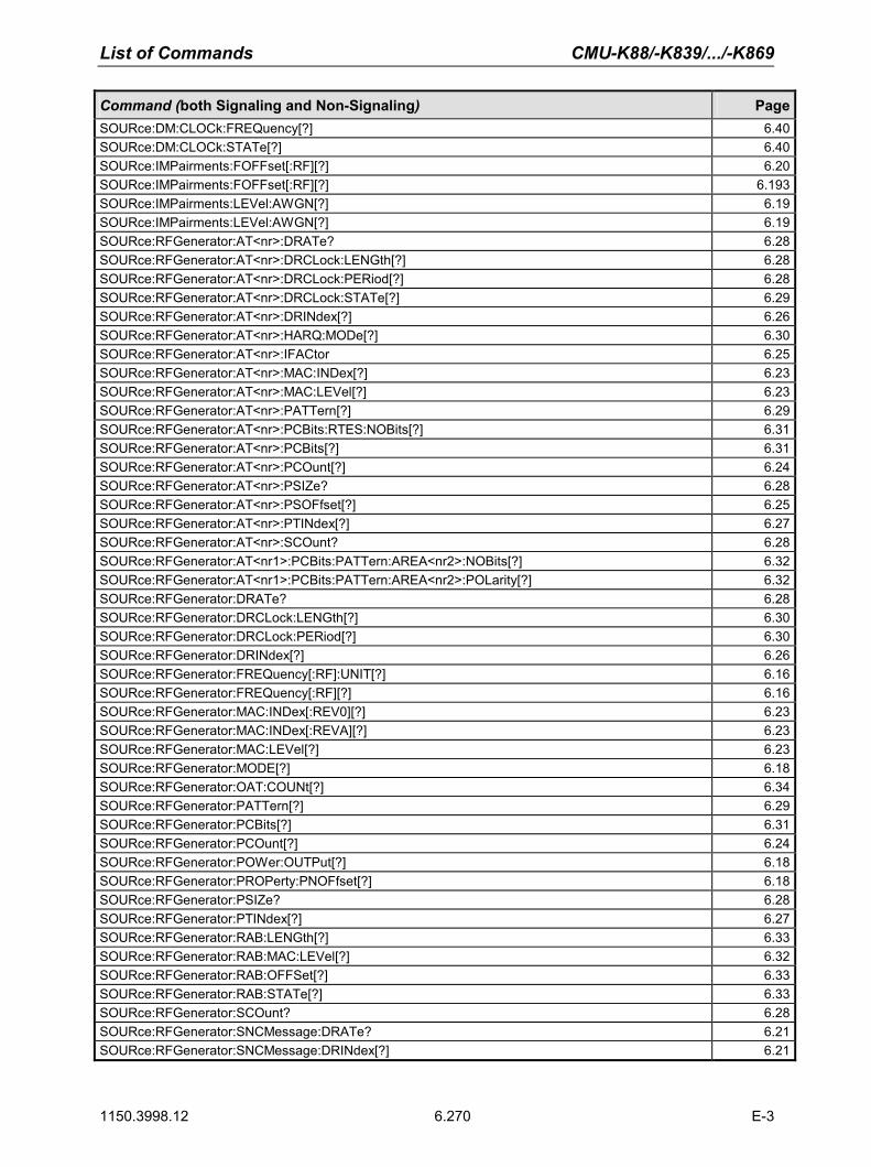
List of Commands CMU-K88/-K839/.../-K869
1150.3998.12 6.270 E-3
Command (both Signaling and Non-Signaling) PageSOURce:DM:CLOCk:FREQuency[?] 6.40SOURce:DM:CLOCk:STATe[?] 6.40SOURce:IMPairments:FOFFset[:RF][?] 6.20SOURce:IMPairments:FOFFset[:RF][?] 6.193SOURce:IMPairments:LEVel:AWGN[?] 6.19SOURce:IMPairments:LEVel:AWGN[?] 6.19SOURce:RFGenerator:AT<nr>:DRATe? 6.28SOURce:RFGenerator:AT<nr>:DRCLock:LENGth[?] 6.28SOURce:RFGenerator:AT<nr>:DRCLock:PERiod[?] 6.28SOURce:RFGenerator:AT<nr>:DRCLock:STATe[?] 6.29SOURce:RFGenerator:AT<nr>:DRINdex[?] 6.26SOURce:RFGenerator:AT<nr>:HARQ:MODe[?] 6.30SOURce:RFGenerator:AT<nr>:IFACtor 6.25SOURce:RFGenerator:AT<nr>:MAC:INDex[?] 6.23SOURce:RFGenerator:AT<nr>:MAC:LEVel[?] 6.23SOURce:RFGenerator:AT<nr>:PATTern[?] 6.29SOURce:RFGenerator:AT<nr>:PCBits:RTES:NOBits[?] 6.31SOURce:RFGenerator:AT<nr>:PCBits[?] 6.31SOURce:RFGenerator:AT<nr>:PCOunt[?] 6.24SOURce:RFGenerator:AT<nr>:PSIZe? 6.28SOURce:RFGenerator:AT<nr>:PSOFfset[?] 6.25SOURce:RFGenerator:AT<nr>:PTINdex[?] 6.27SOURce:RFGenerator:AT<nr>:SCOunt? 6.28SOURce:RFGenerator:AT<nr1>:PCBits:PATTern:AREA<nr2>:NOBits[?] 6.32SOURce:RFGenerator:AT<nr1>:PCBits:PATTern:AREA<nr2>:POLarity[?] 6.32SOURce:RFGenerator:DRATe? 6.28SOURce:RFGenerator:DRCLock:LENGth[?] 6.30SOURce:RFGenerator:DRCLock:PERiod[?] 6.30SOURce:RFGenerator:DRINdex[?] 6.26SOURce:RFGenerator:FREQuency[:RF]:UNIT[?] 6.16SOURce:RFGenerator:FREQuency[:RF][?] 6.16SOURce:RFGenerator:MAC:INDex[:REV0][?] 6.23SOURce:RFGenerator:MAC:INDex[:REVA][?] 6.23SOURce:RFGenerator:MAC:LEVel[?] 6.23SOURce:RFGenerator:MODE[?] 6.18SOURce:RFGenerator:OAT:COUNt[?] 6.34SOURce:RFGenerator:PATTern[?] 6.29SOURce:RFGenerator:PCBits[?] 6.31SOURce:RFGenerator:PCOunt[?] 6.24SOURce:RFGenerator:POWer:OUTPut[?] 6.18SOURce:RFGenerator:PROPerty:PNOFfset[?] 6.18SOURce:RFGenerator:PSIZe? 6.28SOURce:RFGenerator:PTINdex[?] 6.27SOURce:RFGenerator:RAB:LENGth[?] 6.33SOURce:RFGenerator:RAB:MAC:LEVel[?] 6.32SOURce:RFGenerator:RAB:OFFSet[?] 6.33SOURce:RFGenerator:RAB:STATe[?] 6.33SOURce:RFGenerator:SCOunt? 6.28SOURce:RFGenerator:SNCMessage:DRATe? 6.21SOURce:RFGenerator:SNCMessage:DRINdex[?] 6.21

CMU-K88/-K839/.../-K869 List of Commands
1150.3998.12 6.271 E-3
Command (both Signaling and Non-Signaling) PageSOURce:RFGenerator:SNCMessage:PSOFfset[?] 6.21SOURce:RFGenerator:SNCMessage:SCOunt? 6.22SOURce:RFGenerator:SUBType[?] 6.19SOURce:RFGenerator:Type? 6.34STATus:OPERation:SYMBolic:ENABle[?] <Event>,<Event> 6.6STATus:OPERation:SYMBolic[:EVENt]? 6.6STOP:CDPower:CDPW 6.100STOP:CDPower:CHPW 6.120STOP:CDPower:PCDep 6.111STOP:MODulation:EVMagnitude:HPSK 6.69STOP:MODulation:IQANalyzer:HPSK 6.88STOP:MODulation:MERRor:HPSK 6.76STOP:MODulation:MQUality:HPSK 6.47STOP:MODulation:OVERview:HPSK 6.61STOP:MODulation:PERRor:HPSK 6.82STOP:NPOWer 6.56STOP:PING 6.153STOP:RXQuality:CCPer 6.135STOP:RXQuality:FLPer 6.138STOP:RXQuality:FLPFormance 6.144STOP:RXQuality:RLPer 6.148STOP:RXQuality:RLPFormance 6.145STOP:RXQuality:RLQuality 6.141STOP:SAPPower 6.60STOP:SPECtrum:ACP 6.92STOP:WPOWer 6.38STOP:WPOWer 6.215SYSTem:OPTions:INFO:CURRent? 6.2SYSTem:RESet:CURRent 6.2SYSTem:VERSion:SW:MMI? 6.2TRIGger:OUTPut:PIN<nr>:SIGNal[?] 6.42TRIGger:OUTPut:PIN<nr>:SIGNal[?] 6.213TRIGger:SELect:AT[?] 6.41TRIGger[:SEQuence]:SLOPe[?] 6.41TRIGger[:SEQuence]:SLOPe[?] 6.213TRIGger[:SEQuence]:SOURce[?] 6.41TRIGger[:SEQuence]:SOURce[?] 6.211TRIGger[:SEQuence]:THReshold:IFPower[?] 6.43TRIGger[:SEQuence]:THReshold:IFPower[?] 6.212TRIGger[:SEQuence]:THReshold:RFPower[?] 6.43TRIGger[:SEQuence]:THReshold:RFPower[?] 6.212UNIT:ANSignal:CHANnel[:RF][?] 6.192XTND:CDPower:CHPW:RESult:DATa[?] 6.125XTND:SPECtrum:ACP:LIMit[?] 6.59XTND:SPECtrum:ACP:STATistics[?] 6.97
('*) Please note that the commands marked with an asterisk are legacy commands. They still work, but they eventually should be replaced by the new successor commands. The page reference points to the location of the new command description.

CMU-K88/-K839/.../-K869 Program Example
1150.3998.12 7.1 E-2
7 Remote Control – Program Example
The following example program illustrates primary and secondary addressing by setting up a call and performing simple measurements with the CMU. In the example, remote control via GPIB bus and the programming language Winbatch is used.
A large variety of additional GPIB examples can be found on the CMU customer web.
Winbatch uses device names such as CMUBASE, 1xEV-DO-N which are previously defined and assigned to the primary address, secondary address, and some general device settings.
With these device names, a complete command line reads:
CMUBASE: <CMU_Command> where <CMU_Command> may be any of the commands (setting commands or queries) specified within the function group and mode identified by the device name CMUBASE. Program sequences consisting of commands that are defined in several function groups and modes can be re-used with an exchanged device name.
In addition to these data transfer commands, Winbatch provides WHILE, GOTO, and IF statements to express conditions and define loops.
With the statement:
WHILE 1xEV-DO-N: FETC:SPEC:ACP:STAT? <> RDY the instrument waits until the spectrum measurement has finished before it executes the following commands.
For a C program assigning secondary addresses, refer to chapter 7 of the CMU operating manual.
Sample Program (Non-Signaling)
In the program example preliminary configurations for different measurements are defined, and the network parameters are set before performing actual measurements.
Before running the program, configure your Winbatch settings such that CMUBASE is the device name for the CMU BASE system and 1xEV-DO-N denote the function group 1xEV-DO Non-Signaling.
ECHO ON FPRINT --------------------------------------------------------------------- FPRINT INITIALISATION ROUTINE: FPRINT ASK FOR THE IDENTIFIER OF THE CMU, RESET THE INSTRUMENT, FPRINT DEFINE THE SECONDARY ADDRESSES FOR ALL AVAILABLE FUNCTION GROUPS FPRINT --------------------------------------------------------------------- CMUBASE: *IDN? CMUBASE: *RST;*OPC? CMUBASE: *CLS CMUBASE: TRAC:REM:MODE:DISP ON ; Get primary and secondary addresses CMUBASE: SYSTEM:REMOTE:ADDR:PRIM?

Program Example CMU-K88/-K839/.../-K869
1150.3998.12 7.2 E-2
CMUBASE: SYST:REM:ADDR:SEC? ; Set the secondary address of the functional groups CMUBASE: SYST:REM:ADDR:SEC? CMUBASE: SYST:REM:ADDR:SEC 1,"CDMA2K450MS_Sig" CMUBASE: SYST:REM:ADDR:SEC 2,"CDMA2K450MS_NSig" CMUBASE: SYST:REM:ADDR:SEC 3,"CDMA2KCellMS_Sig" CMUBASE: SYST:REM:ADDR:SEC 4,"CDMA2KCellMS_NSig" CMUBASE: SYST:REM:ADDR:SEC 5,"CDMA2KPCSMS_Sig" CMUBASE: SYST:REM:ADDR:SEC 6,"CDMA2KPCSMS_NSig" CMUBASE: SYST:REM:ADDR:SEC 7,"CDMA2KIMT2KMS_Sig" CMUBASE: SYST:REM:ADDR:SEC 8,"CDMA2KIMT2KMS_NSig" CMUBASE: SYST:REM:ADDR:SEC 10,"EVDO1XAT_NSig" CMUBASE: SYST:REM:ADDR:SEC? FPRINT --------------------------------------------------------------------- FPRINT Configure the connector FPRINT --------------------------------------------------------------------- 1xEV-DO-N: INP:STAT RF2 1xEV-DO-N: OUTP:STAT RF2 1xEV-DO-N: SENS:CORR:LOSS:INP2 1.0 1xEV-DO-N: SENS:CORR:LOSS:OUTP2 1.0 FPRINT --------------------------------------------------------------------- FPRINT Network configuration FPRINT --------------------------------------------------------------------- 1xEV-DO-N: CONFigure:NETWork:STANDard USC 1xEV-DO-N: CONFigure:NETWork:STANDard? FPRINT --------------------------------------------------------------------- FPRINT Analyzer configuration FPRINT --------------------------------------------------------------------- 1xEV-DO-N: RFANalyzer:FREQuency:UNIT CH 1xEV-DO-N: RFANalyzer:FOFFset 0 1xEV-DO-N: RFANalyzer:LCMask:I:LSB "00000000" 1xEV-DO-N: RFANalyzer:LCMask:I:MSB "000" 1xEV-DO-N: RFANalyzer:LCMask:Q:LSB "00000000" 1xEV-DO-N: RFANalyzer:LCMask:Q:MSB "000" 1xEV-DO-N: RFANalyzer:CCFilter:DRC DCAR 1xEV-DO-N: RFANalyzer:CCFilter:ACK DCAR 1xEV-DO-N: RFANalyzer:CCFilter:DATA DCAR FPRINT --------------------------------------------------------------------- FPRINT Measurement configuration FPRINT --------------------------------------------------------------------- 1xEV-DO-N: TRIGger:SOURce FRUN ; Ana/Gen 1xEV-DO-N: CONFigure:MODulation:MQUality:HPSK:CONTrol:STATistics 10 1xEV-DO-N: CONFigure:MODulation:MQUality:HPSK:CONTrol:FOFFset:SBSuppress:ACP1 ON 1xEV-DO-N: CONFigure:MODulation:MQUality:HPSK:CONTrol:FOFFset:SBSuppress:ACP2 ON

CMU-K88/-K839/.../-K869 Program Example
1150.3998.12 7.3 E-2
1xEV-DO-N: CONFigure:MODulation:MQUality:HPSK:CONTrol:FOFFset:SBSuppress:ACP3 ON 1xEV-DO-N: CONFigure:MODulation:MQUality:HPSK:CONTrol:FOFFset:SBSuppress:ACP4 ON 1xEV-DO-N: CONFigure:MODulation:MQUality:HPSK:CONTrol:FOFFset:SBSuppress:ACP1? 1xEV-DO-N: CONFigure:MODulation:MQUality:HPSK:CONTrol:FOFFset:SBSuppress:ACP2? 1xEV-DO-N: CONFigure:MODulation:MQUality:HPSK:CONTrol:FOFFset:SBSuppress:ACP3? 1xEV-DO-N: CONFigure:MODulation:MQUality:HPSK:CONTrol:FOFFset:SBSuppress:ACP4? 1xEV-DO-N: CONFigure:MODulation:MQUality:HPSK:CMMax:LIMit? 1xEV-DO-N: CONFigure:MODulation:MQUality:HPSK:AVERage:LIMit? ; NarrowBandPower 1xEV-DO-N: CONFigure:NPOWer:CONTrol:STATistics 10 1xEV-DO-N: CONFigure:NPOWer:CONTrol:CBSize? ; Code Domain Power (Channel Power) 1xEV-DO-N: CONFigure:CDPower:CPCCommon:CMAX:LIMit:ASYMmetric? 1xEV-DO-N: CONFigure:CDPower:CPCCommon:AVERage:LIMit:ASYMmetric? 1xEV-DO-N: CONFigure:CDPower:CHPW:CONTrol:RMODe? 1xEV-DO-N: CONFigure:CDPower:CHPW:CONTrol:STATistics 10 1xEV-DO-N: CONFigure:CDPower:CHPW:CMAX:LIMit:ASYMmetric? 1xEV-DO-N: CONFigure:CDPower:CHPW:AVERage:LIMit:ASYMmetric? FPRINT --------------------------------------------------------------------- FPRINT Generator configuration FPRINT --------------------------------------------------------------------- 1xEV-DO-N: SOURce:RFGenerator:MODE NORM 1xEV-DO-N: SOURce:RFGenerator:FREQuency:UNIT CH 1xEV-DO-N: SOURce:IMPairments:LEVel:AWGN OFF 1xEV-DO-N: SOURce:IMPairments:FOFFset OFF 1xEV-DO-N: SOURce:RFGenerator:PROPerty:PNOFfset 0
; Sync Message 1xEV-DO-N: SOURce:RFGenerator:SNCMessage:PSOFfset 0 1xEV-DO-N: SOURce:RFGenerator:SNCMessage:DRINdex 1 1xEV-DO-N: SOURce:RFGenerator:SNCMessage:DRATe? 1xEV-DO-N: SOURce:RFGenerator:SNCMessage:SCOunt? ; Configuration Access Terminal 1 1xEV-DO-N: SOURce:RFGenerator:AT1:MAC:INDex 63 1xEV-DO-N: SOURce:RFGenerator:AT1:MAC:LEVel -15 1xEV-DO-N: SOURce:RFGenerator:AT1:PCOunt INF 1xEV-DO-N: SOURce:RFGenerator:AT1:PSOFfset 8 1xEV-DO-N: SOURce:RFGenerator:AT1:DRINdex 12 1xEV-DO-N: SOURce:RFGenerator:AT1:DRATe? 1xEV-DO-N: SOURce:RFGenerator:AT1:SCOunt? 1xEV-DO-N: SOURce:RFGenerator:AT1:PATTern "B4B4B4B4" 1xEV-DO-N: SOURce:RFGenerator:AT1:DRCLock:STATe 1 1xEV-DO-N: SOURce:RFGenerator:AT1:DRCLock:PERiod 16 1xEV-DO-N: SOURce:RFGenerator:AT1:DRCLock:LENGth 16 ; Reverse Activity 1xEV-DO-N: SOURce:RFGenerator:RAB:MAC:LEVel -10

Program Example CMU-K88/-K839/.../-K869
1150.3998.12 7.4 E-2
1xEV-DO-N: SOURce:RFGenerator:RAB:STATe 1 1xEV-DO-N: SOURce:RFGenerator:RAB:OFFSet 3 1xEV-DO-N: SOURce:RFGenerator:RAB:LENGth 8 1xEV-DO-N: SOURce:RFGenerator:OAT:COUNt 10 1xEV-DO-N: INIT:RFGenerator;*OPC? 1xEV-DO-N: INIT:RFGenerator:AT1:MAC:INDex 1xEV-DO-N: INIT:RFGenerator:AT1:PSTReam 1xEV-DO-N: SOURce:RFGenerator:POWer:OUTPut -50 1xEV-DO-N: SOURce:RFGenerator:FREQuency 300 1xEV-DO-N: SOURce:RFGenerator:AT1:PCBits HOLD FPRINT --------------------------------------------------------------------- FPRINT Maximum Output Power Measurement FPRINT --------------------------------------------------------------------- 1xEV-DO-N: LEVel:MODE MAN 1xEV-DO-N: LEVel:MAXimum 25dBm 1xEV-DO-N: RFANalyzer:FREQuency 300 1xEV-DO-N: SOURce:RFGenerator:POWer:OUTPut -105.5 1xEV-DO-N: SOURce:RFGenerator:FREQuency 300 1xEV-DO-N: SOURce:RFGenerator:AT1:PCBits AUP 1xEV-DO-N: INIT:MODulation:MQUality:HPSK 1xEV-DO-N: FETCh:MODulation:MQUality:HPSK? 1xEV-DO-N: INITiate:CDPower:CHPW 1xEV-DO-N: FETCh:CDPower:CHPW? FPRINT --------------------------------------------------------------------- FPRINT Minimum Output Power Measurement FPRINT --------------------------------------------------------------------- 1xEV-DO-N: LEVel:MODE MAN 1xEV-DO-N: LEVel:MAXimum -50dBm 1xEV-DO-N: RFANalyzer:FREQuency 300 1xEV-DO-N: SOURce:RFGenerator:POWer:OUTPut -25 1xEV-DO-N: SOURce:RFGenerator:FREQuency 300 1xEV-DO-N: SOURce:RFGenerator:AT1:PCBits ADOW 1xEV-DO-N: INIT:MODulation:MQUality:HPSK 1xEV-DO-N: FETCh:MODulation:MQUality:HPSK? 1xEV-DO-N: INITiate:NPOWer 1xEV-DO-N: FETCh:NPOWer? 1xEV-DO-N: INITiate:CDPower:CHPW 1xEV-DO-N: FETCh:CDPower:CHPW?

CMU-K88/-K839/.../-K869 Program Example
1150.3998.12 7.5 E-2
Sample Programs (Signaling)
Reverse Test Application Call and Queries for CDPower for different Channels
The following example GPIB sequence configures the CMU for a 1xEV-DO Reverse Test Application call and queries for Code Domain Power measurement results for each of the channels:
ECHO ON FPRINT --------------------------------------------------------------------- FPRINT INITIALISATION ROUTINE: FPRINT ASK FOR THE IDENTIFIER OF THE CMU, RESET THE INSTRUMENT, FPRINT DEFINE THE SECONDARY ADDRESSES FOR ALL AVAILABLE FUNCTION GROUPS FPRINT --------------------------------------------------------------------- CMUBASE: *IDN? CMUBASE: *RST;*OPC? CMUBASE: *CLS CMUBASE: TRAC:REM:MODE:DISP ON ; Get primary and secondary addresses CMUBASE: SYSTEM:REMOTE:ADDR:PRIM? CMUBASE: SYST:REM:ADDR:SEC? ; Set the secondary address of the functional groups CMUBASE: SYST:REM:ADDR:SEC 10,"EVDO1XAT_Sig" EVDOSIG: CONF:CDP:CHPW:CONT ARR,10,SING,NONE,NONE ; Configure Network for 1xEVDO Rel 0; USCell; SID 1 ; Chan 150; Power -50dBm EVDOSIG: CONF:NETW:REL 0 EVDOSIG: CONF:NETW:STAN USC EVDOSIG: CONF:NETW:SYST:SID 1 EVDOSIG: CONF:ANS:CHAN 150 EVDOSIG: CONF:ANS:POW:EVDO -50.00 ; Configure Power Control EVDOSIG: CONF:ANS:PCB AUTO ; Configure Foward Packet Activity EVDOSIG: CONF:ANS:FPAC 100 ; Collect all layer tab changes first EVDOSIG: CONF:LAY:UPD:MODE USER ; Setup Reverse TAP on Stream 1 EVDOSIG: CONF:LAY:APPL:DTES:STR 1 EVDOSIG: CONF:LAY:APPL:TEST:SEL REV; *OPC? ; Configure Rate Parameters with probability of 1 EVDOSIG: CONF:LAY:MAC:RTCP:DRCP:ITR:R9K 255 EVDOSIG: CONF:LAY:MAC:RTCP:DRCP:ITR:R19K 255 EVDOSIG: CONF:LAY:MAC:RTCP:DRCP:ITR:R38K 255 EVDOSIG: CONF:LAY:MAC:RTCP:DRCP:ITR:R76K 255 EVDOSIG: CONF:LAY:MAC:RTCP:DRCP:DTR:R19K 255 EVDOSIG: CONF:LAY:MAC:RTCP:DRCP:DTR:R38K 255 EVDOSIG: CONF:LAY:MAC:RTCP:DRCP:DTR:R76K 255 EVDOSIG: CONF:LAY:MAC:RTCP:DRCP:DTR:R15K 255 ; Set Data Channel Gains to 0 dB for all rates EVDOSIG: CONF:LAY:MAC:RTCP:DRCP:DATA:R9K 0.0 EVDOSIG: CONF:LAY:MAC:RTCP:DRCP:DATA:R19K 0.0

Program Example CMU-K88/-K839/.../-K869
1150.3998.12 7.6 E-2
EVDOSIG: CONF:LAY:MAC:RTCP:DRCP:DATA:R38K 0.0 EVDOSIG: CONF:LAY:MAC:RTCP:DRCP:DATA:R76K 0.0 EVDOSIG: CONF:LAY:MAC:RTCP:DRCP:DATA:R15K 0.0 ; Configure the DRC and ACK Channel gains to 0 dB EVDOSIG: CONF:LAY:MAC:FTCP:DFTP:DRC:CGA 0.0 EVDOSIG: CONF:LAY:MAC:FTCP:DFTP:ACK:CGA 0.0 ; Now send all of the above layer parameter updates to the AT EVDOSIG: PROC:SIGN:ACT RNEG;*OPC? ; Ready for test ; Turn the signal on EVDOSIG: PROC:SIGN:ACT SON;*OPC? ; Wait for Session to open REPORT OFF [Wait_SOP] IF EVDOSIG: SIGN:STAT? = SOP GOTO SOP_OK PAUSE 100 GOTO Wait_SOP [SOP_OK] REPORT ON ; Connect TAP call EVDOSIG: PROC:SIGN:ACT CTM;*OPC? [Wait_CALL] IF EVDOSIG: SIGN:STAT? = CEST GOTO CALL_OK PAUSE 100 GOTO Wait_CALL [CALL_OK] FPRINT ----------------------------------------------------------------------- FPRINT Tx Code Domain Power, reverse: 9.6 - 153.6kbps, AN power: -75.0 FPRINT ----------------------------------------------------------------------- ;Set Code channel filters EVDOSIG: RFAN:CCF:DATA ON EVDOSIG: RFAN:CCF:DRC ON EVDOSIG: RFAN:CCF:ACK ON ; Set reference power to pilot power EVDOSIG: CONF:CDP:CHPW:CONT:PRM PPOW PAUSE 2000 ; AN power set to -75dBm EVDOSIG: CONF:ANS:POW:EVDO -75.0;*OPC? EVDOSIG: READ:ARR:CDP:CHPW:AVER? FPRINT ----------------------------------------------------------------------- FPRINT Tx Code Domain Power, reverse: 9.6 FPRINT ----------------------------------------------------------------------- ; Configure RTAP with 9.6K data rate EVDOSIG: CONF:LAY:APPL:DTES:RTAP:DATA:RMIN:IND 1 EVDOSIG: CONF:LAY:APPL:DTES:RTAP:DATA:RMAX:IND 1 EVDOSIG: PROC:SIGN:ACT RNEG;*OPC? ; Wait for data rate change to take effect PAUSE 1000 ; Query for Code Domain Power Results for each Channel EVDOSIG: INIT:CDP:CHPW EVDOSIG: FETC:ARR:CDP:CHPW:AVER? EVDOSIG: ABOR:CDP:CHPW;*OPC? EVDOSIG: READ:ARR:CDP:CHPW:AVER?

CMU-K88/-K839/.../-K869 Program Example
1150.3998.12 7.7 E-2
FPRINT ----------------------------------------------------------------------- FPRINT Tx Code Domain Power, reverse: 19.2 FPRINT ----------------------------------------------------------------------- ; Configure RTAP with 19.2K data rate EVDOSIG: CONF:LAY:APPL:DTES:RTAP:DATA:RMIN:IND 2 EVDOSIG: CONF:LAY:APPL:DTES:RTAP:DATA:RMAX:IND 2 EVDOSIG: PROC:SIGN:ACT RNEG;*OPC? ; Wait for data rate change to take effect PAUSE 1000 ; Query for Code Domain Power Results for each Channel EVDOSIG: INIT:CDP:CHPW EVDOSIG: FETC:ARR:CDP:CHPW:AVER? EVDOSIG: ABOR:CDP:CHPW;*OPC? EVDOSIG: READ:ARR:CDP:CHPW:AVER? ; Repeat for other data rates (38.4, 76.8, 153.6) EVDOSIG: ABOR:CDP:CHPW CLOSEDATA EVDOSIG: PROC:SIGN:ACT CREL

Program Example CMU-K88/-K839/.../-K869
1150.3998.12 7.8 E-2
Default Packet Application Call and Queries for RLP/IP Statistics
The following example GPIB sequence configures the CMU for a 1xEV-DO Default Packet Application call and queries for RLP/IP Statistics.
ECHO ON FPRINT --------------------------------------------------------------------- FPRINT INITIALISATION ROUTINE: FPRINT ASK FOR THE IDENTIFIER OF THE CMU, RESET THE INSTRUMENT, FPRINT DEFINE THE SECONDARY ADDRESSES FOR ALL AVAILABLE FUNCTION GROUPS FPRINT --------------------------------------------------------------------- CMUBASE: *IDN? CMUBASE: *RST;*OPC? CMUBASE: *CLS CMUBASE: TRAC:REM:MODE:DISP ON ; Get primary and secondary addresses CMUBASE: SYSTEM:REMOTE:ADDR:PRIM? CMUBASE: SYST:REM:ADDR:SEC? ; Set the secondary address of the functional groups CMUBASE: SYST:REM:ADDR:SEC 10,"EVDO1XAT_Sig" EVDOSIG: CONF:CDP:CHPW:CONT ARR,10,SING,NONE,NONE ; Configure Network for 1xEVDO Rel 0; USCell; SID 1 ; Chan 150; Power -50dBm EVDOSIG: CONF:NETW:REL 0 EVDOSIG: CONF:NETW:STAN USC EVDOSIG: CONF:NETW:SYST:SID 1 EVDOSIG: CONF:ANS:CHAN 150 EVDOSIG: CONF:ANS:POW:EVDO -50.00 ; Configure Power Control EVDOSIG: CONF:ANS:PCB AUTO ; Configure Foward Packet Activity EVDOSIG: CONF:ANS:FPAC 100 ; Collect all layer tab changes first EVDOSIG: CONF:LAY:UPD:MODE USER ; Setup Default Packet Application on Stream 1 EVDOSIG: CONF:LAY:APPL:DPAC:ENAB ON EVDOSIG: CONF:LAY:APPL:DPAC:STR 1;*OPC? ; Configure Rate Parameters with probability of 1 EVDOSIG: CONF:LAY:MAC:RTCP:DRCP:ITR:R9K 255 EVDOSIG: CONF:LAY:MAC:RTCP:DRCP:ITR:R19K 255 EVDOSIG: CONF:LAY:MAC:RTCP:DRCP:ITR:R38K 255 EVDOSIG: CONF:LAY:MAC:RTCP:DRCP:ITR:R76K 255 EVDOSIG: CONF:LAY:MAC:RTCP:DRCP:DTR:R19K 255 EVDOSIG: CONF:LAY:MAC:RTCP:DRCP:DTR:R38K 255 EVDOSIG: CONF:LAY:MAC:RTCP:DRCP:DTR:R76K 255 EVDOSIG: CONF:LAY:MAC:RTCP:DRCP:DTR:R15K 255 ; Set Data Channel Gains to 0 dB for all rates EVDOSIG: CONF:LAY:MAC:RTCP:DRCP:DATA:R9K 0.0 EVDOSIG: CONF:LAY:MAC:RTCP:DRCP:DATA:R19K 0.0 EVDOSIG: CONF:LAY:MAC:RTCP:DRCP:DATA:R38K 0.0 EVDOSIG: CONF:LAY:MAC:RTCP:DRCP:DATA:R76K 0.0 EVDOSIG: CONF:LAY:MAC:RTCP:DRCP:DATA:R15K 0.0

CMU-K88/-K839/.../-K869 Program Example
1150.3998.12 7.9 E-2
; Configure the DRC and ACK Channel gains to 0 dB EVDOSIG: CONF:LAY:MAC:FTCP:DFTP:DRC:CGA 0.0 EVDOSIG: CONF:LAY:MAC:FTCP:DFTP:ACK:CGA 0.0 ; Now send all of the above layer parameter updates to the AT EVDOSIG: PROC:SIGN:ACT RNEG;*OPC? PAUSE 1000 ; Ready for test ; Turn the signal on EVDOSIG: PROC:SIGN:ACT SON;*OPC? ; Wait for Session to open REPORT OFF [Wait_SOP] IF EVDOSIG: SIGN:STAT? = SOP GOTO SOP_OK PAUSE 100 GOTO Wait_SOP [SOP_OK] REPORT ON
FPRINT ----------------------------------------------------------------------- FPRINT Establish Data Call from Access Terminal and then press any key to continue FPRINT ----------------------------------------------------------------------- waitkey ; Wait for traffic channel connection [Wait_CALL] IF EVDOSIG: SIGN:STAT? = CEST GOTO CALL_OK PAUSE 100 GOTO Wait_CALL [CALL_OK] ; Wait for connection of PPP link [Wait_PPP] IF EVDOSIG: SIGN:STAT:PPP? = CONN GOTO PPP_CONN PAUSE 100 GOTO Wait_PPP [PPP_CONN] ; AN power set to -75dBm EVDOSIG: CONF:ANS:POW:EVDO -75.0;*OPC? EVDOSIG: PROC:SIGN:ACT RNEG;*OPC? PAUSE 2000
FPRINT ----------------------------------------------------------------------- FPRINT Start Data Transfer from the Access Terminal (FTP, Web browsing, etc) and FPRINT press any key to start collecting RLP/IP Statistics FPRINT ----------------------------------------------------------------------- waitkey
FPRINT ----------------------------------------------------------------------- FPRINT Periodically Query for RLP STATS during the entire data session FPRINT ----------------------------------------------------------------------- [Wait_DATA] ; Once the PPP transitions out of Connected, stop the RLP stats collection IF EVDOSIG: SIGN:STAT:PPP? <> CONN GOTO DATA_DONE PAUSE 1000

Program Example CMU-K88/-K839/.../-K869
1150.3998.12 7.10 E-2
; Query for RLP Stats (Tx/Rx IP Packets, Tx/Rx Data Rate) EVDOSIG: RLPS? GOTO Wait_DATA [DATA_DONE] EVDOSIG: ABOR:CDP:CHPW CLOSEDATA EVDOSIG: PROC:SIGN:ACT CREL

CMU-K88/-K839/.../-K869 Maintenance
1150.3998.12 8.1 E-2
8 Maintenance The CMU does not require any special maintenance. Remove any contamination on the instrument by means of a soft cloth. Make sure that the air vents are not obstructed.
Refer to the CMU operating manual detailed maintenance, storage, and packing procedures. The CMU operating manual also contains a list of support and service centers.
Refer to the CMU Service manual for information on troubleshooting, repair, and calibration.

CMU-K88/-K839/.../-K869 Error Codes
1150.3998.12 9.1 E-2
9 Error Codes Table 9-1 lists the error codes and associated messages that may occur when you are using the remote control commands.
Table 9-1 Error Codes
Error Code Message 0 No error -100 Command error -101 Invalid character -102 Syntax error -103 Invalid separator -104 Data type error -105 GET not allowed -108 Parameter not allowed -109 Missing parameter -111 Header separator error -112 Program mnemonic too long -113 Undefined header -113 Undefined header -114 Header suffix out of range -120 Numeric data error -121 Invalid character in number -123 Exponent too large -124 Too many digits -128 Numeric data not allowed -131 Invalid suffix -134 Suffix too long -138 Suffix not allowed -141 Invalid character data -144 Character data too long -148 Character data not allowed -151 Invalid string data -158 String data not allowed -161 Invalid block data -168 Block data not allowed -171 Invalid expression -178 Expression data not allowed -180 Macro error -200 Execution error -211 Trigger ignored -221 Setting conflict

Error Codes CMU-K88/-K839/.../-K869
1150.3998.12 9.2 E-2
-222 Data out of range -223 Too much data -224 Illegal parameter value -230 Data corrupt or stale -240 Hardware error -241 Hardware missing -250 Mass storage error -251 Missing mass storage -252 Missing media -253 Corrupt media -254 Media full -255 Directory full -256 File name not found -257 File name error -258 Media protected -300 Device–specific error -310 System error -311 Memory error -313 Calibration memory lost -314 Save/recall memory lost -315 Configuration memory lost -330 Self test failed -350 Queue overflow -360 Communication error -361 Parity error in program message -362 Framing error in program message -363 Input buffer overrun -400 Query error -410 Query INTERRUPTED -420 Query UNTERMINATED -430 Query DEADLOCKED -440 Query UNTERMINATED after indefinite response

CMU-K88/-K839/.../-K869 Index
1150.3998.12 10.1 E-3
Index
11xEV-DO Power.............................................. 4-140, 6.193
AAccess Cycle Duration ............................................... 6.202 Access network signal
Call loss detection time ........................................ 4-143 Access Offset............................................................. 6.203 Access probe power..................................................... 4-44 Access Probe Power
Signalling ............................................................... 4-43 Access probes mode.................................................. 6.200 Access Terminal
Connection............................................................... 2.2 SELect ................................................................... 6.41 Subsystem, Analyzer ............................................. 6.14 Subsystem, Generator ........................................... 6.22
ACK .................................. 6.12, 6.126, 6.127, 6.128, 6.206 ACK Channel Fix Mode.............................................. 6.166 ACK Channel Fix Mode - FETAP ............................... 6.170 ACK Channel Modulation Type .................................. 6.171 ACP ............................................................................. 6.92 ACP Spectrum ............................................................. 6.92
Remote Control...................................................... 6.92 ACP Spectrum measurement (control)
Remote control ...................................................... 6.93 AN frequency offset ................................................... 4-141 AN frequency offset ..................................................... 4-14 AN PPP Inactivity Timer............................................. 4-129 AN signal
Call loss timer ........................................... 4-143, 6.198 AN Signal................................................................... 6.192 AN Signal Default Settings......................................... 6.192 AN Signal frequency ....................................... 4-117, 4-140 Analyzer .........................................................................4-4 Analyzer Level..................................................... 4-4, 4-160 Analyzer/Generator ...................................................... 4-32 Any Limit Exceeded ........................................ 4-100, 4-101 Application ..................................................................... 3.6
Modulation .................................................... 4-51, 4-72 Receiver Quality .................................................... 4-87
Application layer.........................6.162, 6.163, 6.164, 6.179 Authentication ........................................... 6.178, 6.179
AT Home Agent IP Addr............................................. 4-128 AT Information ........................................................... 4-116
ESN ..................................................................... 6.160 MEID ................................................................... 6.160 UATI .................................................................... 6.160
Attenuation............................................. 4-23, 4-117, 4-148 frequency-dependent ........................................... 4-149
Authentication (PPP).................................................. 4-129 Autoranging....................................................................4-4 Average ....................................................................... 4-38 Average values (calculation) .......................................... 3.8 AWGN............................................................... 6.19, 6.194 AWGN Level ..................................................... 4-14, 4-141 AWGN Power Mode.......................................... 4-14, 4-141
BBand class .......................................................... 6.7, 6.198 Bit reverse.................................................................... 4-79
Code domain power............................................... 4-79
CCall established ..........................................................4-111 Call Loss Detection.....................................................6.198 Call loss detection time...............................................4-143 Call loss timer..................................................4-143, 6.198 Call setup .....................................................................2.12 Care of Address...............................................4-128, 6.175 Carrier feedthrough...................................................... 4-36 Carrier Feedthrough .................................................... 4-50 Carrier frequency error................................................. 4-36 CDPower
CHPW Measurement............................................6.120 Channel power ............................................................ 4-76
Remote control .....................................................6.120 Statistic count.......................................................6.122
Channel power control Remote control .....................................................6.121
Clock Frequency ..............................................................6.40
Clock frequency............................................................6.40 Clock state....................................................................6.40 Closed loop power control .................................4-18, 4-141 Code Channel
ACK............................ 6.12, 6.126, 6.127, 6.128, 6.206 Data ............................................... 6.126, 6.127, 6.128 DATA ..........................................................6.12, 6.206 DRC ........................... 6.12, 6.126, 6.127, 6.128, 6.206 DSC ............................................... 6.126, 6.127, 6.128 Pilot ................................................ 6.126, 6.127, 6.128 RRI................................................. 6.126, 6.127, 6.128
Code Channel Filter Remote Control ...........................................6.12, 6.206
Code domain error power Remote control ..........................................6.100, 6.111
Code domain power..................................................... 4-74 Remote control .....................................................6.100
Code Domain Power Remote control ..........................................6.101, 6.112 Remote control .....................................................6.121
Code domain power configuration ............................... 4-78 Code domain power measurement (control) ................ 4-78 Code Domain Power measurement (control)
Remote control .....................................................6.101 Code Domain Power, I/Q Leakage Check ..................6.105 Color Code .................................................................6.195 Command
Order........................................................................5.7 Structure...................................................................5.1 Tables (description)..................................................5.7
Command Set.................................................................6.2 Confidence Testing.....................................................4-101 Configurations ................................................................3.4 Connected ..................................................................4-111 Connection Control
Handoff.................................................................6.161 Layer ....................................................................6.161
Connection control (NSig).............................................. 4-3 Connection control (Sig) .............................................4-111 Connection layer.........................................................6.181 Connectors (RF) .............................................................2.3 Continuous .....................................................................5.4 Continuous measurement............................................ 4-37 Control Channel power ...............................................6.123 Control Channel...................................................6.15, 6.20 Control Channel PER .................................................. 4-83

Index CMU-K88/-K839/.../-K869
1150.3998.12 10.2 E-3
Counting ........................................................................ 5.4 Country Code............................................................. 6.197 Current......................................................................... 4-38 Current values (parameters)....................................... 6.157
DDATA ................................................................ 6.12, 6.206 Data Channel Modulation Type .................6.14, 6.15, 6.208 Data Channel Modulation, Analyzer .................. 6.14, 6.208 Data Rate.......................................6.21, 6.28, 6.165, 6.170 Data Rate Index ........................................6.21, 6.26, 6.165 Default
Modulation configuration ........................................ 4-64 Default Settings............................. 4-37, 4-47, 4-124, 4-140 Default values (parameters) ....................................... 6.157 Delta marker .............................................................. 4-168 Display mode ................................................................. 3.7 Display Mode
Modulation ............................................................. 4-38 D-Line ........................................................................ 4-169 DRC.................................. 6.12, 6.126, 6.127, 6.128, 6.206 DRCLock Length.......................................................... 6.30 DRCLock Period .......................................................... 6.30 DRCLock State ............................................................ 6.29 DSC ......................................................6.126, 6.127, 6.128 DSC value.................................................................. 6.188
EEnable software ............................................................. 1.9 Error codes .................................................................... 9.1 ESN ........................................................................... 4-116 Exernal (Trigger) ............................................... 4-28, 4-157 Ext. att. input................................. 4-24, 4-117, 4-148, 6.37 Ext. att. output............................... 4-23, 4-117, 4-148, 6.38 External attenuation ............................... 4-23, 4-117, 4-148
frequency-dependent ........................................... 4-149 Remote control ...................................................... 6.37
External Synchronization System Time........................................................ 6.210
External triggering............................................. 4-28, 4-156
FFactory test mode .......................................................... 5.6 FETAP Data Rate Index............................................. 6.169 Filter
Code Channel ............................................. 6.12, 6.206 Foreign Agent Home IP Addr. ......................... 4-128, 6.174 Forward Link PER........................................................ 4-83 Forward Link Performance ........................................... 4-84 Forward Packet Activity .................................... 6.29, 6.198 Frame Period .................................................... 6.42, 6.213 Frequency offset ............................................... 6.20, 6.193
Analyzer................................................................. 6.10 PN ....................................................................... 6.197
Frequency unit ...................................................... 6.9, 6.16 Frequency-dependent external attenuation ................ 4-149
GGain .................................................................. 4-23, 4-148 Generator............................................................ 4-12, 4-21 Generator frequency .............................................4-5, 4-13 Getting started ............................................................... 2.1 GPIB Command Set Version.......................................... 6.2 GPIB commands............................................................ 6.1 GPIB error codes ........................................................... 9.1 Graph
Error....................................................................... 4-54
HHadamard matrix ......................................................... 4-79
Code domain power .............................................. 4-79 HANDoff
Network Standard.................................................6.161 RF channel...........................................................6.161
H-ARQ Mode................................................................6.30 HLT state......................................................................2.11 Home Agent IP Address
AT Node...............................................................6.174 Home Agent Secret ....................................................4-128
AT Node...............................................................6.174 Hotkeys ..........................................................................3.4
II signal
Channel power .....................................................6.126 Long Code Mask ....................................................6.11
I/Q Analyzer Remote control .......................................................6.88
I/Q imbalance .............................................................. 4-50 I/Q origin offset ............................................................ 4-50 I/Q signal
Channel power ............................... 6.126, 6.127, 6.128 Code domain power ..................................6.107, 6.108 Peak code domain error power.............................6.116
I/Q-IF ...............................................4-30, 4-158, 6.4, 6.132 I/Q-IF Interface
remote control ...............................................6.3, 6.132 IF Level ......................................................4-31, 6.5, 6.132 Impairments
Analyzer ........................... 4-5, 4-8, 4-11, 4-162, 4-163 Inactivity Control (PPP) ..............................................4-129 Info ......................................................................6.2, 6.132 Initial Adjustment ........................................................6.200 Installation ......................................................................1.3 Installing software...........................................................1.4
Flash disk .................................................................1.4 Floppy disks .............................................................1.4
Interference (external) ....................................................2.3 Interleaving Factor........................................................6.25 IP address
DNS, dynamic ......................................................6.178 DNS, static ...........................................................6.177 Ping......................................................................4-110 PPP, dynamic.......................................................4-129 PPP, dynamic (AN and AT) ..................................6.178 PPP, static ...........................................................4-129 PPP, static (AN and AT).......................................6.177
IQ Access Interface ......................................................6.35 IQ Leakage Check......................................................6.105 IQ/IF Level..................................................................4-159
LLayer parameter update mode....................................6.162 Limit
Check.......................................................................5.5 Specify .....................................................................5.5
Limit matching Modulation, overview..............................................6.69
Limitmatching Modulation..............................................................6.55
Limits Channel Power, CHPW ........................................6.124 Code Domain Power ............. 6.97, 6.103, 6.105, 6.114 Code Domain Power ............................................6.124 Code domain power measurement ........................ 4-81 Code Domain Power, CDPW.......................6.97, 6.105

CMU-K88/-K839/.../-K869 Index
1150.3998.12 10.3 E-3
Code Domain Power, CPCCommon6.103, 6.114, 6.124 I/Q Leakage Check .............................................. 6.105 Modulation .................................................... 6.51, 6.65 Modulation measurement, signaling.............. 4-39, 4-64 Modulation, OEMP............................... 6.65, 6.66, 6.67 Peak Code Domain Error Power .......................... 6.114 Peak Code Domain Error Power, PCDep............. 6.114 Spectrum measurement, signaling ......................... 4-70
Limits (Modulation)....................................................... 4-39 List of Commands ...................................................... 6.214 Literal ............................................................................. 5.7 Long Code Mask.......................................................... 6.11
I signal ................................................................... 6.11 LSB........................................................................ 6.11 MSB....................................................................... 6.11 Q signal ................................................................. 6.11
Loopback FETAP................................................................. 6.170 FTAP ................................................................... 6.166
LSB Long Code Mask .................................................. 6.11
MMAC Index ........................................................ 6.23, 6.195 MAC layer ....................................................... 6.183, 6.189 MAC Level .......................................................... 6.23, 6.32 Main power switch ......................................................... 2.2 Maintenance .................................................................. 8.1 Manual control ............................................................... 3.1 Markers...................................................................... 4-168 Max. PER Exceeded.................................................. 4-100 Maximum PER ........................................................... 4-103 Measurement
Control ..................................................................... 5.2 Measurement groups ..................................................... 3.4 Measurement object....................................................... 5.2 Measurement Subtype ...................................... 6.11, 6.205 MEID.......................................................................... 4-116 Menu select ................................................................... 2.4 Menu structure ............................................................... 3.1 Messages, error ............................................................. 9.1 Min. Conf. Lev. Exceeded .......................................... 4-100 Min. Confidence Level................................................ 4-103 MIP Authentication Type ................................. 4-128, 6.177 MIP Stand Alone Mode .............................................. 4-127 Mobile Node Home IP Addr............................. 4-127, 6.174 Modulation
Analyzer/Generator ....................................... 4-34, 4-66 Narrow Band Power............................................... 4-43 Remote control .................................... 6.71, 6.77, 6.83 Remote control ...................................................... 6.61
MODulation OEMP, limits................................................. 6.65, 6.67
Modulation configuration ..................................... 4-36, 4-47 Modulation configuration. ............................................. 4-63 Modulation measurement ............................................. 4-48
Remote control ...................6.47, 6.61, 6.69, 6.76, 6.82 Modulation measurement (control) ...................... 4-37, 4-47
Remote control ..........6.47, 6.61, 6.69, 6.76, 6.82, 6.88 Remote control ............................................. 6.48, 6.71
Modulation Overview configuration Remote control ...................................................... 6.63
Modulation quality configuration Remote control ...................................................... 6.48
Modulationmeasurement(control) Remotecontrol .............................6.63, 6.77, 6.83, 6.89
MP Agent Advertisements............................... 4-128, 6.175 MSB Long Code Mask ................................................. 6.11
NNarrow band
Statistics.................................................................6.58 Narrow Band Power......................................................6.56 Network release..........................................................6.199 Network Standard..................................... 6.7, 6.198, 6.199 Networks Supported .......................................................1.3 Nominal Offset............................................................6.201 Notation
Remote control .........................................................5.7 NPower
Repetition ...............................................................6.59 NPOWer.......................................................................6.56
Remote control .......................................................6.58 NPower measurement(control)
Remote control .......................................................6.58 Number of Bits.....................................................6.31, 6.32 Number P Bits ............................................................6.196
OOEMP...........................................................................6.91 OEMP measurements ..................................................6.91 OEMP Modulation ........................................................6.91 On Limit Failure ........................................................... 4-38 Operating concept ..........................................................3.1 Options (Setup)
remote control ...............................................6.1, 6.132 Orthogonal Variable Spreading Factor......................... 4-79 Other Access Terminal Count.......................................6.34 Out of tolerance........................................................... 4-36 Out of Tolerance
Modulation, EVM....................................................6.74 Modulation, magnitude error...................................6.80 Modulation, phase error..........................................6.86
Output power................................................................6.18 Output Power .........................................4-13, 4-117, 4-140 Output Routing ..................................................6.42, 6.213 Overall Sector ID .............................................6.196, 6.197 OVSF .......................................................................... 4-79
PPacket Count................................................................6.24 Packet Size ..................................................................6.28 Packet Size (ping).......................................................6.155 Packet Size (Ping) ......................................................4-110 Packet Start Offset .....................................6.21, 6.25, 6.33 Packet Type Index........................................................6.27 Packing ..........................................................................8.1 Parameter
command .................................................................5.7 Current vs. default ................................................6.157
Partial reset .........................................................6.2, 6.132 Password (PPP authentication) ..................................4-129 Pattern..........................................................................6.29 Peak code domain error power .................................... 4-76 Peak Code Domain Error Power
PCDep..................................................................6.111 Remote control .....................................................6.111
Peak code domain power measurement (control) Remote control .....................................................6.112
Physical layer .............................................................6.192 Pilot ...........6.100, 6.107, 6.108, 6.111, 6.116, 6.117, 6.118 Pilot Strength
Correction Max. ....................................................6.204 Correction Min. .....................................................6.204 Nominal ................................................................6.203
Ping Configuration ......................................................4-109 remote control ......................................................6.154

Index CMU-K88/-K839/.../-K869
1150.3998.12 10.4 E-3
Ping Count ...................................................... 4-110, 6.154 Ping measurement
remote control...................................................... 6.153 Ping measurement ..................................................... 4-107 PN Offset ..................................................................... 6.18 Polarity......................................................................... 6.32 Power (wide band) ............................................ 4-24, 4-149
Remote control (Sig) ................................... 6.60, 6.153 Power (wideband)
remote control............................................. 6.38, 6.215 Power control bits ............................................. 4-18, 4-141 Power Control Bits ............................................ 6.31, 6.194 Power measurements ................................................ 6.132
example ................................................................... 2.6 Power switch.................................................................. 2.3 PPP ........................................................................... 4-129 PPP Authentication Type ........................................... 4-129 PPP Connected ......................................................... 4-112 PPP off ...................................................................... 4-112 Preamble Length........................................................ 6.202 Preamble Length (Slots)............................................. 6.202 Primary address............................................................. 5.1 Probe Increment......................................................... 6.201 Probe Timeout Adjust................................................. 6.203 Probes per Sequence ................................................ 6.201 Program example........................................................... 7.1
QQ signal
Code domain power.................................. 6.107, 6.108 Long Code Mask.................................................... 6.11
RRAB Length.................................................................. 6.33 RAB State .................................................................... 6.33 range test..................................................................... 6.31 Recall
current .......................................................... 6.3, 6.132 Receiver quality
remote control 6.135, 6.138, 6.141, 6.144, 6.145, 6.148 Receiver Quality.................................................. 2.16, 4-83 Receiver Quality (control)............................................. 4-99 Receiver Quality (limits) ............................................. 4-101 Receiver Quality Configuration..................................... 4-98 Ref. ............................................................................ 4-168 Reference frequency.................................................... 4-25
Remote control ...................................................... 6.40 Reference line............................................................ 4-169 Reference marker ...................................................... 4-168 Registration Reply Code ................................. 4-128, 6.176 Registration Reply Lifetime ............................. 4-128, 6.176 Rel. 2 ......................................................................... 4-168 Remote control
basics ...................................................................... 5.1 Commands .............................................................. 6.1 Notation ................................................................... 5.7 Program example..................................................... 7.1
Repeat Interval................................................ 4-110, 6.155 Repetition
ACP Spectrum....................................................... 6.94 Channel power..................................................... 6.123 Code domain power............................................. 6.102 Modulation .................................................. 6.50, 6.132 Modulation .................................................. 4-37, 4-100 Modulation, EVM ................................................... 6.72 Modulation, IQ Analyzer......................................... 6.89 Modulation, magnitude error .................................. 6.78 Modulation, overview ............................................. 6.64 Modulation, phase error ......................................... 6.84
NPower ..................................................................6.59 Peak code domain................................................6.113 Ping......................................................................6.154
Repetition mode ......................................................3.6, 5.4 Report mode.................................................................6.56 Reset.......................................................................2.4, 2.5 Result
ACP Spectrum........................................................6.97 Channel power .....................................................6.125 Code domain power .............................................6.106 Error vector magnitude ...........................................6.74 IQ Analyzer.............................................................6.91 Magnitude error ......................................................6.80 Modulation overview...............................................6.68 Modulation quality ..................................................6.54 Narrow band power ................................................6.59 Peak code domain error power.............................6.115 Phase error ............................................................6.86 Receiver quality statistics overview ...........6.134, 6.156 Wide band power ........................................6.40, 6.217
Result (power) ............................................................. 4-73 Result mode
Channel power .....................................................6.122 Code domain power .............................................6.101 Modulation, EVM....................................................6.71 Modulation, IQ Analyzer .........................................6.89 Modulation, magnitude error...................................6.77 Modulation, phase error..........................................6.84 Peak code domain................................................6.112
Result order Code domain power .............................................6.102 Peak code domain................................................6.113
RETAP Max. Data Rate Index ....................................6.172 RETAP Min. Data Rate Index .....................................6.171 Reverse Activity Bit ......................................................6.33 Reverse Link Frame Offset ...........................................6.14 Reverse Link PER ....................................................... 4-85 Reverse Link Performance .......................................... 4-84 Reverse Link Quality ................................................... 4-83 RF channel
AN Signal ..................................................4-117, 4-140 Generator ....................................................... 4-5, 4-13
RF Channel unit..........................................................6.192 RF Channel/Frequency...............................................6.193 RF connector..................................................................2.2 RF Connector in/out....................................................4-117 RF Connector Out ......................................................4-117 RF connectors ...................................2.3, 4-22, 4-147, 6.37 RF frequency..................................................4-5, 6.9, 6.16 RF generator ................................................................6.15
mode ......................................................................6.18 Remote control .......................................................6.15 signal subtype ........................................................6.19
RF input.........................................4-23, 4-117, 4-148, 6.37 RF level, mode ....................................................6.8, 6.205 RF Max. Level ...................................4-4, 4-160, 6.8, 6.205 RF Mode............................................................. 4-4, 4-160 RF output..................................................4-23, 4-147, 6.37 RFANalyzer
Remote control ..............................................6.8, 6.204 Rho factor.................................................................... 4-50 RLP / IP Statistics measurement ................................4-104
remote control ......................................................6.152 Routing (Trigger)................................................4-28, 4-157 RRI ....................................................... 6.126, 6.127, 6.128 RRl ............6.100, 6.107, 6.108, 6.111, 6.116, 6.117, 6.118 RTAP Max. Data Rate ................................................6.168 RTAP Max. Data Rate Index ......................................6.167 RTAP Min Data Rate ..................................................6.168 RTAP Min. Data Rate Index .......................................6.167 RX Path...........................................4-31, 4-159, 6.4, 6.132

CMU-K88/-K839/.../-K869 Index
1150.3998.12 10.5 E-3
SSave
current .......................................................... 6.3, 6.132 SCPI standard................................................................ 5.2 Secondary address ................................................. 5.1, 5.6 Sector Access Rate (Max.) ........................................ 6.203 Sector ID Low Bits ..................................................... 6.196 SectorID
Format ................................................................. 6.196 Select Access Terminal................................................ 6.41 Session Info ............................................................... 4-116 Session layer ............................................................. 6.180 Session negotiation.................................................... 4-111 Session Open ............................................................ 4-111 Sideband frequency offset
Modulation .................................................... 4-39, 6.50 Signal off.................................................................... 4-111 Signal on.................................................................... 4-111 Signaling .................................................................... 4-111
Remote control .................................................... 6.158 Signaling layer ........................................................... 6.161 Signaling Setup.......................................................... 4-117 Signaling state ........................................................... 6.159 Signaling State........................................................... 6.159 Signaling states.......................................................... 6.158 Single shot ..................................................................... 5.4 Single-shot measurement ............................................ 4-37 Slot Count ......................................6.22, 6.28, 6.166, 6.170 Softkeys......................................................................... 3.4 Software
Update and installation ............................................ 1.1 Software (enable)........................................................... 1.9 Software configuration ................................................... 1.7 Special character ........................................................... 5.8 Spectrum ..................................................................... 6.92
Remote control ...................................................... 6.93 Spectrum configuration. ............................................... 4-69 Standby and Access Probe power
Remote control (Sig) .............................................. 6.60 Standby mode................................................................ 2.3 Standby power ............................................................. 4-44 Startup menu .......................................................... 1.3, 2.2 Statistic count ....................................................... 4-75, 5.4
ACP Spectrum....................................................... 6.93 Channel power..................................................... 6.122 Code domain power............................................. 6.101 Modulation ............................................................. 6.49 Modulation, EVM ................................................... 6.71 Modulation, magnitude error .................................. 6.78 Modulation, overview ............................................. 6.64 Modulation, phase error ......................................... 6.83 Peak code domain .................................... 6.112, 6.113
Statistic count ..................................................... 4-36, 4-46 Statistic Count................................................................ 3.6
Modulation ............................................................. 4-38 Statistical PER Tests ................................................. 4-101 Statistical quantities ....................................................... 3.8 Statistics
NPower.................................................................. 6.58 Remote control ........................................................ 5.3
Statistics cycle ............................................................... 3.6 STATus
OPERation register .................................................. 6.6 OPERation register - Symbolic evaluation ............... 6.6
Status indication.................................................... 2.7, 2.11 Status reporting system ................................................. 5.5 Status symbols............................................................... 3.2 Stepping mode
ACP Spectrum....................................................... 6.94 Channel power..................................................... 6.123
Code domain power .............................................6.102 Modulation..............................................................6.50 Modulation, EVM....................................................6.72 Modulation, IQ Analyzer .........................................6.89 Modulation, magnitude error...................................6.78 Modulation, overview..............................................6.64 Modulation, phase error..........................................6.84 Peak code domain................................................6.113 Ping......................................................................6.154
Stop condition ACP Spectrum........................................................6.94 Channel power .....................................................6.123 Code domain power .............................................6.102 Modulation..............................................................6.50 Modulation, EVM....................................................6.72 Modulation, IQ Analyzer .........................................6.89 Modulation, magnitude error...................................6.78 Modulation, overview..............................................6.64 Modulation, phase error..........................................6.84 Peak code domain................................................6.113 Ping......................................................................6.154
Stop Condition ................................................................3.7 Modulation...................................................4-38, 4-100
Storing............................................................................8.1 Stream layer ...............................................................6.180 Subarrays
Modulation, EVM....................................................6.73 Modulation, IQ Analyzer .........................................6.90 Modulation, magnitude error...................................6.79 Modulation, phase error..........................................6.85
Subnet Mask ..............................................................6.197 Symbolic evaluation of status register......................5.5, 6.6 Sync. Message....................................................6.15, 6.20 Synchronization
Remote control .......................................................6.40 system time ..........................................................6.209
System ID Number .....................................................6.200
TTest mode ......................................................................2.6 Test modes.....................................................................3.1 Tests
1xEV-DO................................................................. 4-2 1xEV-DO Non-Signaling........................................ 4-32 1xEV-DO Non-Signaling and Signaling.................. 4-41 1xEV-DO Signaling ............................................... 4-83
Threshold IF Power ...........................................6.43, 6.212 Threshold RF Power..........................................6.43, 6.212 Time synchronization
remote control ......................................................6.209 Timeout (ping) .................................................4-110, 6.155 Trace ..............................................................................5.4 Transmit time error ...................................................... 4-36 Trigger ...............................................................4-27, 4-156
remote control .............................................6.41, 6.211 Trigger IF power level .................................................4-157 Trigger Output ...................................................6.42, 6.213 Trigger output routing .................................................4-157 Trigger RF power level ...............................................4-157 Trigger slope...............................................................4-157 Trigger Slope.....................................................6.41, 6.213 Trigger source ...................................................6.44, 6.211 Trigger source ..........................................4-28, 4-29, 4-157 Triggering
External .......................................................4-28, 4-156 TX Path ...........................................4-31, 4-159, 6.4, 6.132

Index CMU-K88/-K839/.../-K869
1150.3998.12 10.6 E-3
UUATI .......................................................................... 4-116 Update period ................................................. 6.133, 6.152 Update Period (Receiver Quality).................... 4-100, 4-105 Updating software .......................................................... 1.4 Use AT IP Address (Ping) ............................... 4-110, 6.155 Username (PPP authentication) ................................. 4-129
VVersion........................................................................... 6.2
Version manager ............................................................1.4
WWaveform quality......................................................... 4-50
Modulation.................................................... 4-55, 4-60 Waveform quality......................................................... 4-36 White noise........................................................6.19, 6.194 White noise, Gaussian.......................................6.19, 6.194 Wideband power
remote control .............................................6.38, 6.215 Wideband Power ...............................................4-24, 4-149