2 0 2011 - dspace@mit home
TRANSCRIPT

Basic Communication Framework for a Robotic Device for
the Inspection of Nuclear Reactor Piping Structures
by
Meagan Roth
Submitted to the Department of Mechanical Engineering in partial fulfillment of therequirements for the degree of
Bachelors of Science in Mechanical Engineering
at the
MASSACHUSETTS INSTITUTE OF TECHNOLOGY
June 2011
@ Massachusetts Institute of Technology 2011. All rights reserved.
Signature of A uthor................................. . . ... .'...... .... ...
Departnnt of Mechanical EngineeringMay 6, 2011
Certified by......................................... . H. Harry Asada
Ford Professor of Mechanical EngineeringThesis Supervisor
Accepted by ......................... ................... ...............John H. Lienhard V
Samuel C. Collins ro o Mechanical EngineeringUndergraduate Officer
MA77770
OCT 2 0 2011
Li ! rA R I ES
ARCHIVES


Basic Communication Framework for a Robotic Device for
the Inspection of Nuclear Reactor Piping Structures
by
Meagan Roth
Submitted to the Department of Mechanical Engineeringon May 6, 2011, in partial fulfillment of the
requirements for the degree ofBachelors of Science in Mechanical Engineering
Abstract
Remotely Operated Vehicles (ROVs) have a wide variety of underwater applications.Controlling these robots wirelessly in an aquatic environment is challenging because ofsignal attenuation. This challenge is made even more difficult when this environmentis the complex internal structure of a nuclear reactor. The cooling pipes of nuclearreactors are prone to corrosion along their weld lines. Traditional inspection methodsare difficult, dangerous, and labor intensive. This thesis describes the development ofa robotic architecture that implements two different kinds of wireless communication,radio and optical, that will allow for exploration and documentation of these pipes.This proposed architecture capitalizes on the best aspects of each communicationmethod. In this system, two robots would be built that would work in tandem todocument the pipe welds. One robot would communicate optically with the surfaceand via radio with the second robot who would explore the reactor. Additionallythis thesis focused on developing the supporting software and electronics necessaryto implement the proposed communication model. The electronics were refined toa Printed Circuit Board (PCB) which could be used in a wide variety of roboticfunctions.
The culmination of this thesis placed the developed electronics and program intoan alpha prototype robot. This robot was used to analyze the movement of the a robotthrough water using a new type of propulsion mechanism. This first implementationof the designed software and electronics illustrates the adaptability of this work andits potential application in many iterations.
Thesis Supervisor: H. Harry AsadaTitle: Ford Professor of Mechanical Engineering

4

Acknowledgments
I would like to thank Professor Asada for teaching 2.12 which ultimately led to my
thesis. He accepted me as one of his thesis students and allowed me to work on
a project that I found both interesting and challenging. Without his support and
sponsorship my thesis would not have been as enjoyable and product of an experience.
I also owe a debt of gratitude to Anirban Mazumdar. He was a fantastic TA in
2.12 and an even better mentor through my thesis. His patience and guidance led
me to learn more from this project than I ever could have hoped. He took the time
to teach me many new things about electronics in mechanical engineering and was
always willing to help me with any of my projects. This project also could not have
been completed without the help of Martin Lozano. His development of an integral
piece of software was key to the success of this project. I would also like to thank
the rest of the guys in the D'Arbeloff lab for making my thesis and lab something I
really enjoyed going to.
My biggest thank you goes to my mom, dad, brother and grandparents. For four
years they've patiently listened to my stories in garbled engineering speak and nodded
along. Regardless of wether my stories made sense, or if they actually cared about
the subject, I could always count on them to be sympathetic or supportive, whatever
the case may be.

6

Contents
1 Introduction 15
1.1 Remote Controlled Underwater Devices......... . . . . . . .. 15
1.2 Previous Work......... . . . . . . . . . . . . . . . . . . . . . 16
1.3 Motivation... . . . . . . . . . . . . . . . . . . . . . . . . . . . . . 17
1.4 Problem Statement . . . . . . . . . . . . . . . . . . . . . . . . . . . . 19
1.5 O utline of Paper . . . . . . . . . . . . . . . . . . . . . . . . . . . . . 19
2 Underwater Communication 21
2.1 Types of Communication.......... . . . . . . . . . . . . . .. 21
2.2 Acoustics ................ . . . . . . . . . . . . . . . .. 21
2.3 Optical(Light)....... . . . . . . . . . . . . . . . . . . . . . . .. 22
2.4 R adio . . . . . . . . . . . . . . . . . . . . . . . . . . . . . . . . . . . 24
2.4.1 Testing of Transmittance.... . . . . . . . . . . . . . . .. 25
2.4.2 Experimental Setup...... . . . . . . . . . . . . . . . . . . 25
3 Robotic Habitat 31
3.1 Introduction........... . . . . . . . . . . . . . . . . . . . . . 31
3.2 Application of Methods of Communication... . . . . . . . . . . . 32
3.2.1 Application of Acoustics.......... . . . . . . . . . .. 32
3.2.2 Application of Optics....... . . . . . . . . . . . . . . . . 33
3.2.3 Application of Radio . . . . . . . . . . . . . . . . . . . . . . . 34
3.2.4 Application Summary......... . . . . . . . . . . . . . 35
3.3 Sum m ary . . . . . . . . . . . . . . . . . . . . . . . . . . . . . . . . . 35

4 Wireless Control Architecture
4.1 Introduction . . . . . . . . . . . . . . . . . . . .
4.2 Robotic Hierarchy..... . . . . . . . . . . .
4.3 Modeling of Hierarchy with Current Equipment
5 Robotic Functions
5.1 Introduction . . . . . . . . .
6 Printed Circuit Board (PCB)
6.1 PCB Development . . . . .
6.2 PCB Design . . . . . . . . .
6.3 PCB Application . . . . . .
7 Testing
7.1 Test Model . . . . . . . . .
7.2 Model Design . . . . . . . .
7.3 Testing Devices . . . . . . .
7.4 Results. . . . . . . . . . . .
7.5 Conclusion. . . . . . . . . .
8 Conclusion
8.1 Overview. . . .
8.2 Future Work .
8.3 Application .
A Arduino Controller Code
47
47
47
48
. .. . . . . . . .
. . . . . . . . . .
. . . . . . . . .
. . . . . . . . . . .
. . . . . . . . . . .
. . . . . . .
. ..... . . . . .
. . . . . . . . . . .
. . . . . . . . . . .
. . . . . . . . . . .
. . . . . . .
. . . . . . . . . .
. . . . . . . . . .
. . . . . . . . . .
. . . . . . . . . .
. . . . . . . . . .
. . . . . . . . . .
. . . . . . . . . .
. . . . . . . . . .
. ..... .. . .. .. . .. .. . .. .. . ... . . .
. . ..... .. . .. .. . .. .. . ... . . . . . .
. ..... ... ... .. . . . . . . . . . . .

List of Figures
1-1 This spherical robot has a internal gimbal mechanisms that allows the
camera to be rotated freely without the use of external thrusters or
propellers. Because of this movement the robot is called The Eyeball. 17
1-2 Water enters the device through the bottom nozzle. By covering the
gaps on either side of the body of the device the water can be directed
out of the opposite exit port. A solenoid is used to switch which body
hole is covered. . . . . . . . . . . . . . . . . . . . . . . . . . . . . . . 18
2-1 Penetration depth of different colors of light in water. Blue light pen-
etrates the deepest, making it an ideal candidate for optical communi-
cation . . . . . . . . . . . . . . . . . . . . . . . . . . . . . . . . . . . . 23
2-2 The antenna is used to pass a signal from the computer to another
antenna in a separate waterproof box. This signal is used to turn on
a light and check the transmittance distance of the radio signal. The
battery and cable used to connect to the computer are not shown. . . 26
2-3 The receiving antenna as well as the circuit necessary to support the
LED light are contained in a waterproof box. The light is not pictured.
When used, the LED light is placed inside the box as well as weights
to sink the container. This light is used to test transmittance distance
of radio waves underwater........ . . . . . . . . . . . . . . . . 27
2-4 Visible in this picture is the LED light turning on at the maximum
distance of 2.3 meters. On the right is the transmitter box and the
cable running to the computer sitting on the edge of the pool. .... 28

2-5 This graph plots Radio Penetration Depth (RPD) against water qual-
ity. The experimentally verified pool water RPD and expected nuclear
reactor RPD are labeled. . . . . . . . . . . . . . . . . . . . . . . . . 28
3-1 This diagram shows the approximate dimensions of the reactor that
the robot is intended to investigate. . . . . . . . . . . . . . . ... 32
3-2 The robot can maintain contact with the surface through optical com-
munication but cannot inspect the weld.. . . . . . . . . . . . . . 34
3-3 With radio communication, the robot would be able to inspect the
weld and send videos, but the signal is not strong enough for the . . 35
4-1 Two robots using two different forms of communication would be capa-
ble of inspecting the weld and relaying video or pictures to the surface. 38
5-1 MATLAB was used to create a GUI. The user input from this GUI
was used to remotely control an underwater robot . . . . . . . . . . . 42
5-2 A depiction of the workstation used to test the pin functionality of the
Arduino Mini board. The LED light is used to test if the correct pin
is responding to used input. . . . . . . . . . . . . . . . . . . . . . 43
5-3 The original electronic layout of the radio communication and motor
board inside of the Eyeball robot. The wires clearly take up a signifi-
cant volume of the internal space. . . . . . . . . . . . . . . . . . . . 44
6-1 A schematic PCB design for the wireless control of underwater robots.
This schematic incorporates an Arduino Mini, radio receiver, motor
controller and connections for solenoids and pumps. . . . . . . . . . 48
6-2 The final PCB schematic was converted into a representation of the ac-
tual PCB board. The footprint of each element as well as the necessary
connections are displayed on the 3 inch by 3 inch board itself. .... 49

7-1 A SolidWorks model of the Coanda Jet device testing robot. The red
box is waterproof and contains the electronics necessary to operate the
pumps, not pictured, and the solenoids, white. The Coanda devices
can be seen in blue. The black hull of the boat was 3D printed. . . . 52
7-2 Robot made to test the Coanda jet devices. The electronics necessary
for the radio control, pumps, and solenoid are held within the opaque
box. Tubes direct the water from the Coanda device inside of the boat
hull to the outer edge of the hull. These streams of water are used to
propel and steer the boat. . . . . . . . . . . . . . . . . . . . . . . . . 52
7-3 Captured image of the test robot at 0 seconds and at 34cm as marked
on the container. This series of still shots from a movie of hte boat
was used to calculate its velocity. . . . . . . . . . . . . . . . . . . . . 53
7-4 Captured image of the test robot at 0.5 seconds and at 41cm as marked
on the container. This series of still shots from a movie of hte boat
was used to calculate its velocity...... . . . . . . . . . . . . . . 54
7-5 Captured image of the test robot at 1 second and at 48cm as marked
on the container. This series of still shots from a movie of hte boat
was used to calculate its velocity.......... . . . . . . . . . . . 55
7-6 Captured image of the test robot at 1.5 seconds and at 57cm as marked
on the container. This series of still shots from a movie of hte boat
was used to calculate its velocity..... . . . . . . . . . . . . ... 55
7-7 Captured image of the test robot at 2 seconds and at 76cm as marked
on the container. This series of still shots from a movie of hte boat
was used to calculate its velocity. . . . . . . . . . . . . . . . . . . . . 56
7-8 Plot of angular position against time as the boat is rotated clock-
wise and then counter clockwise. Slope of portions of the graph were
measured to calculate the steady state rotational velocity. Angular
velocities of respective time frames are labeled.... . . . . . . . . 57

12

List of Tables
2.1 Penetration depth of radio waves in varying qualities of water. Con-
ductivity of different types of water. . . . . . . . . . . . . . . . . . . . 25

14

Chapter 1
Introduction
1.1 Remote Controlled Underwater Devices
Robots have been developed to take the place of humans to perform tedious, difficult,
or dangerous tasks. Some of the most difficult tasks take place underwater. In these
locations remote controlled robots can be utilized to solve problems where humans
would fall short. Removing humans from these dangerous locations and directing a
robot with a remote control creates safer and more effective missions.
Remotely Operated Vehicles (ROV's) are underwater vehicles controlled by a user
at the surface. Normally this control is performed through the use of a tether, a bundle
of cables for directing the robot, that provides power and receives images or video [1].
ROV's have a wide variety of applications including offshore hydrocarbon extraction,
shipwreck investigation, and observation and capture of deep water sea life [2]. These
robots can be used in underwater situations beyond just the deep sea - in locations
that are hazardous or difficult to gain access to.
A location that lends itself to the use of ROV's is the cooling pipes of a nuclear re-
actor. The welds in these pipes are prone to corrosion and are difficult and dangerous
to inspect. These pipes are a challenge to inspect because the system is radioactive,
hot (260'C),highly pressurized (20.6 MPa), and the diameters of the pipes of interest
are around 80 cm [3]. The reactor is obviously extremely dangerous, and the current
method for inspecting the welds is labor intensive and time consuming. If an ROV

were to be used, the small pipe size places a restriction on external features and sen-
sors. Additionally, the sensors present in the reactor act as hang ups for any type of
tether, the normal method for controlling an ROV.
If the ROV cannot be tethered in the conventional method it must be controlled
remotely. The layout of the reactor presents challenges when implementing wireless
remote control that cannot be solved with current methods. In order to create a
small, wireless ROV for the purpose of inspecting welds in a nuclear reactor a novel
solution is necessary. This thesis focused on developing a wireless control hierarchy,
developing the supporting programs and electronics, and implementing a first level
prototype.
1.2 Previous Work
Previous work has been done on the particular problem of inspecting the welds in
nuclear reactor pipes. Most of this work has focused on the mechanical elements
that are necessary to navigate and perform the desired functions in such a restrictive
environment.
One project has been the development of the "EyeballROV" [4]. This robot, seen
in Fig. 1-1, utilizes a unique internal gimbal mechanism to rotate and tilt the camera
around the body of the robot.
This positioning method allows the robot to inspect 3600 of the pipe weld without
using external thrusters or propellers. This ability to rotate in space is a critical fea-
ture in allowing the welds to be thoroughly inspected. The lack of external propellers
or fins keeps the robot from becoming entangled. This gimbal device is operated with
one internal motor that rotates and eccentric mass. Moving the center of mass of the
robot causes it to rotate in the water.
Additional work has been done on propulsion in water without external fixtures
and navigation and steering in low Reynolds number situations. External features
could snag within the reactor and low Reynolds number situations make steering
difficult with fins or rudders. The propulsion device seen in Fig. 1-2 uses the Coanda

Figure 1-1: This spherical robot has a internal gimbal mechanisms that allows thecamera to be rotated freely without the use of external thrusters or propellers. Be-cause of this movement the robot is called The Eyeball.
effect to propel and steer a robot[5].
The device designed to take advantage of the Coanda effect, is a simple branched
structure which can be mounted inside of a robot. A pump is used to push water
through the nozzle at the bottom of the device and a solenoid is used to change which
exit nozzle the flow uses.
This thesis used the previous work in this field and focused on making these
proposed mechanisms communicable with the surface. The previous work address the
mechanical challenges faced in an environment such as a nuclear reactor. Without
the ability to communicate effectively with the surface these devices will not be able
to perform their respective tasks. This thesis sought to develop a method to control
the previously designed robot and receive information without interfering with the
intended mechanical functions. These robots laid the framework for the capabilities
that would be required of the electronics and communication software.
1.3 Motivation
Inspecting the water filled pipes of the cooling systems of nuclear reactors can be a
difficult and dangerous job. The system is hot, radioactive, pressurized, dark and

Figure 1-2: Water enters the device through the bottom nozzle. By covering the gapson either side of the body of the device the water can be directed out of the oppositeexit port. A solenoid is used to switch which body hole is covered.
studded with obstacles. This type of dangerous location would greatly benefit from
the use of an unmanned underwater robot. The robots would function in an environ-
ment that is to hazardous for humans to inspect without expensive and labor intensive
preparation. These robots could navigate smaller spaces like the interior of pipes to
inspect welds where it would be difficult to place a human. Their wireless capabilities
also mean that the robot is far less likely to become entangled in an interior sensor.
This need for a small wireless robot that can navigate the pipes of a nuclear reactor
and actively inspect welds with instruction from the surface presents a number of
challenging issues. One of the largest issues that arises in this reactor scenario is how
to effectively and wireless communicate with a small robot in the confines of a steel
reactor.

1.4 Problem Statement
The unique structure of a nuclear reactor cooling systems presents problems not
previously faced by underwater robotic inspection teams. One of these problems is
how to communicate wirelessly with a small, underwater robot who is not always
visible to the operator. Not only must this robot follow directions from the surface,
it must also be able to transmit back real time video or picture so that the operator
can actively inspect the welds inside of the pipes for corrosion. The problem that this
thesis sought to address was the implementation of a robotic system that could be
wirelessly controlled in the underwater nuclear reactor environment actively enough to
inspect welds in pipes and fast enough to past pictures or videos to the surface. This
included the software necessary to process commands and operate separate mechanical
elements, the electronics necessary to power the elements inside of the robot, and
finally a first order prototype utilizing the all these components.
1.5 Outline of Paper
This paper begins with an overview of different types of communication used in
robotics and their performance in an underwater situation. Chapter 2 also shares
the results of testing of theoretical models of the underwater performance of radios.
Chapter 3 explains in more detail the layout of the reactor and the challenges faced
by the robot. These challenges shaped the solution developed in this thesis and
therefore need to be addressed thoroughly. Chapter 4 explains the solution developed
for implementing underwater wireless control and how this solution was move from
conceptual to physical. Chapter 5 shows the culmination and finalization of the
electrical system designed in this thesis. Chapter 6 describes the development of
a PCB schematic and design. Finally Chapter 7 shows the implementation of this
electronic layout and program in a first level robot prototype.

20

Chapter 2
Underwater Communication
2.1 Types of Communication
The best method of underwater communication is to be tethered to the robot by a ca-
ble which can transmit information. This tether prevents any information from being
lost or distorted traveling through the water and allows for fast communication[1].
However, this tether becomes a liability that can be wrapped or entangled around
structures while the robot is maneuvering. It can also interfere with the rotation of
the robot. In the nuclear reactor setting described in the introduction, the maneuver-
ability of the robot is a key feature for inspecting the pipe welds. Additionally, many
sensor are mounted inside of the reactor for monitoring purposes. These structures
could easily ensnarl the tether of a robot. These physical constraints point to the need
for a wireless control system. However, there is no single wireless method available
that would succeed in this scenario.
2.2 Acoustics
Acoustic are often used in underwater communication. Sound travels faster in water
than it does in air. Even at its fastest, acoustics can only be used to transmit data at
a rate of 150 kbps [6]. With the primary goal of the robot being to send pictures to the
surface so that the welds on the pipes can be inspected, 150 kbps is not fast enough
[6]. Additionally, acoustic communication is affected by the propagation of the waves.
The reflection of the acoustic waves off of the interior surface of the reactor as well
as the surface of the water in such a small space could pose a serious problem in
interpreting a clear signal from the robot. Finally, the equipment utilized in acoustic
communication is large enough as to be prohibitive [6].
2.3 Optical(Light)
Besides acoustics, another method of communication is optical. Light waves are
much faster than acoustic waves and can be used to send data at a rate fast enough
to transmit pictures and even video??. Light energy is absorbed quickly by water
and the distance over which information can be transmitted, and received, is short,
less than 300 meters. The actual distance that the light can travel is more applicable
in larger scale operations. In this application the distance necessary is around 20
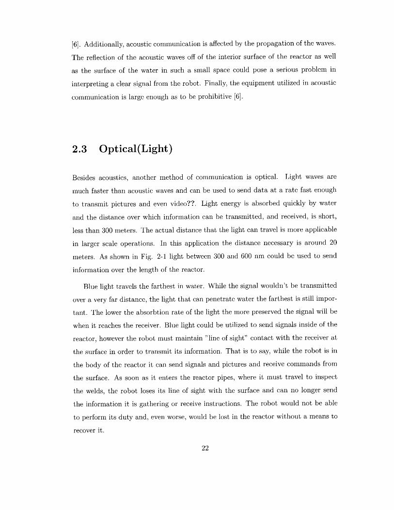
meters. As shown in Fig. 2-1 light between 300 and 600 nm could be used to send
information over the length of the reactor.
Blue light travels the farthest in water. While the signal wouldn't be transmitted
over a very far distance, the light that can penetrate water the farthest is still impor-
tant. The lower the absorbtion rate of the light the more preserved the signal will be
when it reaches the receiver. Blue light could be utilized to send signals inside of the
reactor, however the robot must maintain "line of sight" contact with the receiver at
the surface in order to transmit its information. That is to say, while the robot is in
the body of the reactor it can send signals and pictures and receive commands from
the surface. As soon as it enters the reactor pipes, where it must travel to inspect
the welds, the robot loses its line of sight with the surface and can no longer send
the information it is gathering or receive instructions. The robot would not be able
to perform its duty and, even worse, would be lost in the reactor without a means to
recover it.
white Light(ai coks; but sepwated
for uisuizaton)
400 500 W~o 700 S00(orr
Oepth
100
200
300
Figure 2-1: Penetration depth of different colors of light in water. Blue light pene-
trates the deepest, making it an ideal candidate for optical communication.
200
t t t

2.4 Radio
Pure water is an insulator. When salts and other materials become suspended in
the water it starts to behave like a conductor. The higher the conductivity of the
water, the faster a radio signal attenuates [7]. The water used in the nuclear reactor
has been purified, but a radio signal aimed to control a robot would attenuate to an
unusable level over a distance of less than ten meters. The attenuation of the radio
signal can be described as [8]
I(x) = Io exp(-xy) (2.1)
Where I is the intensity of the signal, x is the distance from the signal source, Io
is the initial intensity of the signal and 'y is the propagation constant of radio waves
in a certain quality of water. The propagation constant is calculated by
-y (rpo-f)2 (2.2)
where p is the magnetic permeability of water, o- is the conductivity of the water
and f is frequency. Using 7, a simpler equation can be derived to calculate the
penetration of light into water. The Radio Penetration Depth (RPD) is calculated
where
RPD = 23 7 (2.3)
The rate at which the signal attenuates is affected by the type of signal being used
as well as the purity of the water through which it is being transmitted. The signal
was said to be attenuated when it was at I of its original strength. Table 1 shows10
the RPD of different radio signals in different water qualities.

Radio Frequency Deionized water Distilled Water Tap Water Sea WaterRPD RPD RPD RPD
240 (MHz) 236 (in) 106 (in) 2.72 (in) 0.32 (in)430 (MHz) 176 (in) 79 (in) 2.04 (in) 0.24 (in)1.4 (GHz) 97 (in) 43 (in) 1.13 (in) 0.13 (in)2.4 (GHz) 75 (in) 34 (in) 0.86 (in) 0.1 (in)o- Conductivity 10-5 5x10⁻⁵ 2.72 5.5(Siemons/m)
Table 2.1: Penetration depth of radio waves in varying qualities of water. Conduc-tivity of different types of water.
The water in the reactor is believed to have a purity between that of distilled
water and tap water. The radio used for this robot is 430 Hz. While the RPD of
distilled water (79 m) would exceed the needed transmittance distance, the RPD of
tap water is less than desired. Because the distance the radio needed to travel in the
reactor was close to the predicted RPD of the reactor water, testing of the theoretical
model was necessary.
2.4.1 Testing of Transmittance
The predicted values seen in table 1 give indication that radio could potentially be
used for controlling a robot in the nuclear reactor setting. Testing was necessary to
verify that the robot would be able to transmit a signal over a suitable distance in
water of conductivity level equal to that of the water in the reactor.
2.4.2 Experimental Setup
In order to test the the theoretical model of attenuation of radio waves in water,
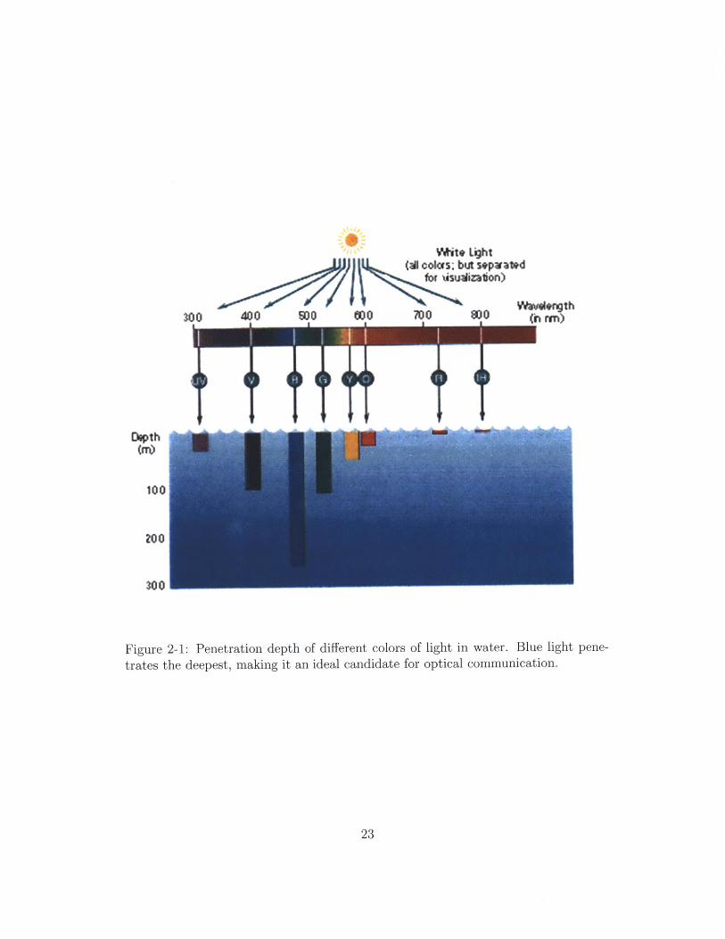
a simple experiment was performed. In this experiment a signal was sent from a
computer to an antenna in a waterproof box at the bottom of a pool via a hardwire
connection as seen in Fig. 2-2.
A similar antenna and waterproof box setup, as seen in Fig. 2-3, was place at
the other end of the pool. This box held a radio receiver, battery for the radio,
breadboard, LED light, and battery for the light.
Figure 2-2: The antenna is used to pass a signal from the computer to another antennain a separate waterproof box. This signal is used to turn on a light and check thetransmittance distance of the radio signal. The battery and cable used to connect tothe computer are not shown.
26

Figure 2-3: The receiving antenna as well as the circuit necessary to support the LEDlight are contained in a waterproof box. The light is not pictured. When used, theLED light is placed inside the box as well as weights to sink the container. This lightis used to test transmittance distance of radio waves underwater.
The antenna in the second box was wired to an LED light that would switch on
and off with the commands sent from the computer. The second box relied only on
the instructions is received via radio waves underwater from the first box to turn the
light on and off. During the experiment the box with the light was moved away from
the first antenna until the signal was no longer received by the second antenna. When
the box had reached the RPD of the water in the pool the light in the box would no
longer flicker on and off. This distance was measured and compared to theoretical
values. The experimental setup can be seen in Fig. 2-4.
By using the simple experimental method described earlier it was determined
that the distance that the radio could transmit in pool water was 2.3 meters. The
experimental result was in line with the value predicted using the model described
earlier and seen in Fig. 2-5.
The model can be used to predict the distance that radio waves can travel in the
nuclear reactor without fear that the prediction will be skewed. Given the purity of

Figure 2-4: Visible in this picture is the LED light turning on at the maximumdistance of 2.3 meters. On the right is the transmitter box and the cable running tothe computer sitting on the edge of the pool.
251 1 1
20
0-15E
C0
10
C
5
'0 0.02 0.04 0.06 0.08 0.1Conductivity (Siemens/m)
0.12 0.14 0.16
Figure 2-5: This graph plots Radio Penetration Depth (RPD) against water quality.The experimentally verified pool water RPD and expected nuclear reactor RPD arelabeled.
Reactor Water
c = 0.005, depth = -8m
Pool Waterc= 0.075, depth= -2m

the water in the reactor, it was predicted that radio waves could travel 8 meters before
attenuating to an unusable level. The graph in Fig. 2-5 shows the curve created using
Eq. 2.3 and the relative locations of the water tested and the water in the reactor.

30

Chapter 3
Robotic Habitat
3.1 Introduction
The nuclear reactor that the robots will be exploring is composed of two separate
sections which define the way in which the robot must communicate with the surface.
The water holding chamber is composed of a larger holding tank and pipes that
branch off to flow through the reactor and cool it. A representation of the reactor,
weld location, and approximate dimensions can be seen in Fig. 3-1
The nuclear reactor layout presents numerous challenges to the robot, particularly
in terms of communicating with the surface. Traditional methods of communication
fall short in this environment because water attenuates electromagnetic waves and
the location of the weld places the robot out of sight of the surface. The traditional
tether method of communication is not suitable for this robot either because the
robot cannot be encumbered by something that would reduce its freedom to move or
become tangled. Additionally, all 3600 of the pipe must be inspected and video sent
back to the surface in realtime. The realtime video or picture stream is important
because it allows the operator to actively access the weld and recognize locations
that need closer inspection without bringing the robot back to the surface or out of
the pipe. This saves time and ensures that potential corrosion points aren't lost or
overlooked.

2-3 mWeld 23
Figure 3-1: This diagram shows the approximate dimensions of the reactor that therobot is intended to investigate.
3.2 Application of Methods of Communication
As mentioned earlier, there were three wireless forms of communication considered for
this application, Each method had its own benefits and drawbacks given this specific
scenario.
3.2.1 Application of Acoustics
Acoustics are commonly used in underwater communication. However, they were
quickly ruled out for any application in this project. In this nuclear reactor scenario
a robot that is small enough to fit into the pipe to inspect the weld will be too small
to house the acoustic equipment necessary to transmit and receive information[6] .
In addition, the highest frequency acoustics are not fast enough to transmit data at
a rate capable of sending videos. The metal in the reactor a well as the branching
structure of the reactor will cause the waves to bounce and become distorted. These
features automatically rule out acoustics as a viable form of communication in the

reactor setting and for sending pictures of the welds.
3.2.2 Application of Optics
The second method of communication discussed was optical. In this aquatic applica-
tion, blue light would be used to send information because that color maintains the
highest integrity through water. When pulsed quickly, light can be used to send bits
of information fast enough to pass pictures and even video. Light travels through wa-
ter faster and attenuates slower than radio waves. The stronger the light source used
for transmitting the data inititially, the farther it can travel before attenuating to a
non-useable level.This implies that the best light source for this application would
be a laser. However, using a laser to transmit information requires a high level of
precision from both the surface transmitter sending information to the robot and the
robot sending information back to the receiver.
This drawback can be overcome with the use of certain LED lights [6]. These
lights are bright enough to travel a useable distance through the water and also cast
a greater area of light than a laser. Even with the broader target provided by using
an LED array, the robot must remain in line of sight contact with the surface as well
as maintain proper orientation. The robot would be able to send signals in the body
of the reactor,but from this location it would not be able to record the welds. If the
robot entered the pipes to the point it could record video of the welds it would not
be able to optically transmit the data to the surface. The problem faced by the robot
can be seen in Fig. 3-2.
Another alternative option to communicating with the robot would be to program
it to go to the weld location, video the weld and return to the surface with this
information. This model doesn't allow for greater inspection of problem areas in
the weld, adjustment of the trajectory of the robot, and the precision necessary to
navigate through the reactor to the welds would be difficult to program. The robot
would not be dynamic enough to satisfy the needs of those inspecting the welds.

Figure 3-2: The robot can maintain contact with the surface through optical commu-nication but cannot inspect the weld.
3.2.3 Application of Radio
Radio control is an excellent solution for terrestrial robots, but has drawbacks when
translating to water. Radio can transmit information at a high enough rate to send
pictures or video in both air and water. However, radio waves attenuate quickly in
water and are only viable over short distances. The 8 meter transmitter distance
predicted using Eq. 2.3 and validated through experiments, would be strong enough
to send signals from the weld to the body of the reactor but it would not be strong
enough to reach the surface from the weld sight. If the operator tried to control
the robot with just radio communication the robot would reach a depth where it
could not be controlled by the operator at the surface and could potentially be lost
in the reactor. Fig. 3-3 illustrates the challenge that a robot controlled only by radio
communication would have.

Figure 3-3: With radio communication, the robot would be able to inspect the weldand send videos, but the signal is not strong enough for the
3.2.4 Application Summary
The wireless methods described fall short when used in the nuclear reactor environ-
ment. No method of communication is capable of being used to send large pieces of
information, like a picture, in realtime to the surface while being inside of the pipes
of the reactor. Acoustic communication becomes distorted and requires large, bulky
equipment, radio waves attenuate too quickly, and optical communication fails as
soon as the robot is out of sight of the receiver.
3.3 Summary
Because of the geometric and medium restrictions involved in the case of exploring the
welds in the pipes of a nuclear reactor, current models of robotic communication and
exploration fall short. Communicating in water is a great hinderance to most means of
communication, and the geometry of the reactor rules out the communication modes

that are options in water. The robot must explore small (80 cm diameter) pipes.
This restrict the size of the robot thus ruling out the larger equipment needed for
acoustic communication. The pipes place the robot out of visual contact with the
surface and prevent optical communication from being used. The distance that the
robot must transmit signals prevents radio communication with the surface from its
location inside of the pipes. Clearly the current options will not due in this scenario
and a creative communication solution is necessary for this project to more forward.

Chapter 4
Wireless Control Architecture
4.1 Introduction
From the advantages and disadvantages apparent in each form of wireless communi-
cation, it was apparent that utilizing two separate means of communication would
yield the desired ability to communicate wirelessly with the surface at speeds fast
enough to send video or pictures. By combining optical and radio communication an
operator at the surface of the reactor would be able to wirelessly use ROVs to inspect
the pipe welds and receive visual information. These two separate communication
types would be placed inside of two individual robots who would then work together
to relay information to the surface as seen in Fig. 4-1.
4.2 Robotic Hierarchy
This dual robot system employs a "relay" robot as well as an "explorer" robot. In
Fig. 4-1 the relay robot would be the red robot and the explorer robot is the yellow
robot. The relay robot maintains two separate methods of two way communication.
This robot uses optical communication to communicate with the surface, receiving
instructions and passing back pictures or video. This robot filters the information
it gets from the surface and decides if the instruction is meant for itself or for the
explorer robot. The relay robot maintains radio communication the short distance

Figure 4-1: Two robots using two different forms of communication would be capableof inspecting the weld and relaying video or pictures to the surface.
down the pipe with explorer robot and passes, or relays, information from the surface.
The explorer robot performs these surface commands and transmits the pictures it
takes back to the relay robot. This robot utilizes radio communication over optical
communication because it must be able to maneuver freely without concern for orien-
tation in order to photograph all parts of the pipe. Radio is an acceptable means of
communication between the explorer robot and the relay robot because information
is only transmitted between two and three meters.
If, for example, the operator at the surface wanted the explorer robot to rotate
and take another photograph he would input this in the control panel at the surface.
This message would be passed optically to the relay robot. The relay robot would
process this information, recognize that the message was for the explorer robot, and
pass the instructions on to the explorer robot through a radio signal. The explorer
robot receives this command and then proceeds to follow the directions and snap a
picture. The new photographs taken by the explorer robot are passed back to the
surface through the same channels.
4.3 Modeling of Hierarchy with Current Equip-
ment
Available in lab where this thesis was carried our was a robot similar in structure to the
explorer robot described in the previous section. The eyeball robot described in the
introduction and shown in Chapter 1 will be used to test the radio control proposed
for the explorer robot. Modeling the relay robot will be done with a computer and a
user interface connected to a radio transmitter. The computer will be used to control
the explorer robot and prove that radio can be used to control an underwater robot.
Proving that underwater radio communication is a viable option is an important
first step before committing to building fully functioning explorer and relay robots.
This model allows the functionality of the code written for the explorer robot as well
as the practicality of radio instruction to be tested before the relay robot is designed
and built. Some of the features that the final iteration of the explorer robot will need
are not incorporated into the current model. This will not affect the functionality
of the Arduino Mini code written to handle the radio communication. The circuitry
used in this robot will be designed, built and programmed as if it were for the fully
functioning robot design proposed earlier.

40
Chapter 5
Robotic Functions
5.1 Introduction
The relay robot in this nuclear reactor scenario is required to perform a variety of
tasks. The robot must move forward, backward, stall, pitch, yaw, and roll. This wide
breadth of actions is necessary so that the robot can maneuver through the reactor
and photograph the entire pipe weld. The software for this robot must be able to
process user input for all of these commands as well as a command for resetting the
camera. Additionally, it should be easy to modify in case more or less functions are
desired. The electronics inside of this robot must activate different pieces of hardware
on operator command processed through the software.
This robot was controlled by an Arduino Mini Pro 3.3V 8 MHz board. This was
run with Arduino software downloaded to the chip through a mini usb connection.
This board interfaced with an EZRadio ER400TRS, Pololu Motor controller, XBEE
mini USB explorer and /mu CAM, solenoid controller, and 2 pump controllers. This
electronic setup was designed in such a manner that the robot would be ale to utilize
the programmed commands to move forward , backward, turn, reset the camera
and rotate. The commands for the robot were placed through a GUI developed in
MATLAB. This graphic can be seen in Fig. 5-1.
When the MATLAB GUI was utilized it would send commands through the serial
port to an antena which would transmit these signals to an antenna connected with

Figure 5-1: MATLAB was used to create a GUI. The user input from this GUI was
used to remotely control an underwater robot.
the EZ-RADIO and arduino setup described earlier. The program on the Arduino
Mini functions on single character commands corresponding to discrete commands
on the GUI interface. The code and single character command sequence can be seen
in Appendix A. When the code processed the user input a corresponding pin on the
Arduino Mini board would be turned on or off. These pins were then routed to their
corresponding mechanical elements. The pins could not be connected directly ot the
elements mentioned earlier. Instead, voltage regulators, capacitors and Mosfets were
used to give the appropriate power and signal to each element in the robot.
When the operator used the GUI interface a characters was sent to the serial port
and then transmitted via radio transceiver. The commands were realized by the EZ-
Radio receiver on the separate relay robot board and passed to the Arduino Mini.
Further programming, described above, used this character to turn different pins on
the circuit board on or off. The code could be easily tested using the Arduino pins,
power source and LED light. Instead of fully wiring the bread board to each solenoid,
pump and the camera setup the light was used as an indicator of functionality. The
full testing set-up - including power supply, electronics, LED light and user interface
can be seen in Fig 5-2.

Figure 5-2: A depiction of the workstation used to test the pin functionality of theArduino Mini board. The LED light is used to test if the correct pin is respondingto used input
43

The LED light was utilized because it was a quick and simple way to test each pin
and command during the development process of the code as well as the interface with
radio communication. The basic signal sent in all cases, except that of the motor,
was on or off. The motor had to have three settings, on, off and reverse, and had to
be used for the testing of those series of commands. Forward, backward and reverse
are achieved by using two pins. Only one pin on indicates forward, only the other
pin on indicates backwards and both off is stopped. For the camera reset the light,
or power to the camera as it represents, turns off for three seconds and then back on.
The circuitry for these commands were housed inside of the prototype built pre-
viously and seen in Fig. 1-1. When the electronics, wiring, and elements necessary
to only run the gimbal mechanism were placed in this prototype they took up a
significant amount of space in the cavity as seen in Fig. 5-3.
Figure 5-3: The original electronic layout of the radio communication and motorboard inside of the Eyeball robot. The wires clearly take up a significant volume ofthe internal space.
The relay robot is not expected to be larger than the Eyeball robot prototype.
The amount of wiring necessary to operate this robot and the small space in which it
must fit presents many challenges. The wiring is difficult to complete and check, the

robot is difficult to assemble and problem shoot and the volume of wires takes up so
much space in The cavity that it restricts the movement of the gimbal device. The
electronic design seen in 5-3 was a first iteration of what would be necessary for this
robot to be completed. It was evident that the number of wires had to be decreased
and that the electronics had to be easier to assemble.

46
Chapter 6
Printed Circuit Board (PCB)
6.1 PCB Development
A PCB layout was created in order to reduce the wiring and electrical components
exposed inside the cavity of the robot and to make assembly easier. The quantity
of wires in the first iteration restricted the movement of the Eyeball robot's internal
gimbal device. When the robot was used the wires would become entangled, caus-
ing the motor attached to the gimbal device to stall. The code, wiring, and overall
designed proved functional, however refinement of the implementation of the design
was necessary to ensure that the robot could complete its tasks. In further proto-
types, a PCB board will simplify the assembly process and the area occupied by the
electronics. This PCB will eliminate the issues cause by excessive wires and their
entanglement of gimbal device.
6.2 PCB Design
Integrated into the PCB board are the Arduino Mini, the EZ Radio Receiver and
antenna, motor controller as well as their power supply set up. The board was also
designed with a series of capacitors in order to reduce noise. The footprint for the
solenoids, pumps, and motors are not integrated into this PCB board. Instead, the
board has a series of male pins that can be connected to different items used inside of

the robot. This gives future designers the ability to place mechanical elements, such
as pumps and solenoids, freely about the robot with little concern to their placement
on the PCB. The PCB is a three inch square. This small size allows it to fit inside
current prototypes and inside of the waterproof boxes used for testing. The PCB was
made as small as possible so its size would not be a limiting factor when designing
robots in the future.
6.3 PCB Application
The PCB for this robot was designed using the software program Eagle. The schematic
was designed using the design parameters discussed above. The final PCB schematic
can be seen in Fig.6-1.
.,,z~I1-4-
IfI4
Figure 6-1: A schematic PCB design for the wireless control of underwater robots.This schematic incorporates an Arduino Mini, radio receiver, motor controller andconnections for solenoids and pumps.
The final board layout was created using the Autoroute function in Eagle. The

schematic layout is used to quickly and easily place items into a PCB and connect
them appropriately. The autoroute function optimizes these connections and creates
a wiring patterns that best suit the board layout desired. Eagle was used to label
separate pins and features on the PCB board for ease of assembly in the future. The
final PCB board can be seen in Fig. 6-2. This board is a representation of what will
be placed into the robot. The pins were arranged in such a manner that mechanical
devices could easily be connected without crossing other components' leads. Isolated
items, the arduino, radio reciver and voltage regulators, are placed at the center of
the board.
Figure 6-2: The final PCB schematic was converted into a representation of the actualPCB board. The footprint of each element as well as the necessary connections aredisplayed on the 3 inch by 3 inch board itself.
The PCB used in this application is three inches square and holds the electrical
components necessary to run the separate mechanical elements that would run a

robot. This small size makes it adaptable to a variety of robot styles and designs.

Chapter 7
Testing
7.1 Test Model
The test model for this experiment utilizes the Coanda jet devices mentioned in the
introduction and the PCB board designed in this thesis. Currently the Eyeball ROV
is not self propelled. It has the capability to pitch ad yaw using the internal gimbal
device but cannot move forward or backwards. The Coanda jet devices are a good
option in the low flow environment of the nuclear reactor. Pumps are used to force
water through the inlet and the switching of the solenoid causes the jet stream to
switch which exit port it leaves through[5]. The dynamic nature of the code and PCB
allow them to be used to control both the Eyeball robot and the Coanda test robot.
7.2 Model Design
The purpose of this test model is to begin to test the Coanda jet devices, as seen
in Fig. 1-2. The Coanda devices will be used for propulsions and yawing. The first
iteration of of this model can be seen in Fig. 7-1,
This actual test robot made from this solid model concept can be seen in Fig. 7-2
For ease of testing the central part of the robot is a waterproof box that houses the
electronic components necessary for the pumps, solenoids and radio control. Around
this box is an acrylic mounting bracket. The jets are mounted to this bracket and
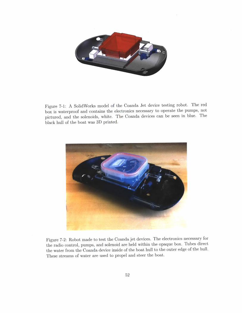
Figure 7-1: A SolidWorks model of the Coanda Jet device testing robot. The redbox is waterproof and contains the electronics necessary to operate the pumps, notpictured, and the solenoids, white. The Coanda devices can be seen in blue. Theblack hull of the boat was 3D printed.
Figure 7-2: Robot made to test the Coanda jet devices. The electronics necessary forthe radio control, pumps, and solenoid are held within the opaque box. Tubes directthe water from the Coanda device inside of the boat hull to the outer edge of the hull.These streams of water are used to propel and steer the boat.

the entire assembly is connected to the boat body. Tubes run from each exit port in
the Coanda devices to the holes in the shell of the boat. The tubes cause the streams
of water from the robot to enter the surrounding water at the same point in space.
This will reduce the torque felt from the offset of the jets.
7.3 Testing Devices
This test robot was designed to simply, quickly, and cheaply test the capabilities of
the Coanda devices. The robot can be seen in Figs. 7-3 - 7-7. The waterproof box
in the center of the robot houses the PCB board. The wires from the pumps and
solenoids are passed through slots drilled in the sides of the box. The pumps and
solenoids are attached to a frame mounted to the waterproof box. This simple set up
allows for testing of the behavior of the Coanda devices when used for driving and
steering.
The first experiment measured the velocity of the boat starting from zero velocity.
The boat can be seen crossing a container filled with water in Figs. 7-3 to 7-7.
Figure 7-3: Captured image of the test robot at 0 seconds and at 34cm as marked onthe container. This series of still shots from a movie of hte boat was used to calculateits velocity.

Figure 7-4: Captured image of the test robot at 0.5 seconds and at 41cm as markedon the container. This series of still shots from a movie of hte boat was used tocalculate its velocity.
The boats progress across the tank was measured with a digital camera. The
camera takes video at a rate of 30 frames per second and this was used with the
distance traveled over a series of still frames was used to calculate the velocity of
the boat. The video analysis of the boat's velocity was performed using the program
virtual dub.
The angular velocity capabilities of the boat were measured using a similar pro-
cedure. The boat began a turn from a zero velocity position, continued to rotate for
approximately 3 seconds and then the actuators were immediately reversed, causing
the boat to rotate in the opposite direction. The video of the rotating boat was also
analyzed using the software VirtualDubs. Still frames 0.5 seconds apart were cap-
tured from the video. These frames were used to plot the change in angular position
of the boat with respect to time. To calculate the rotation of the boat at a certain
point in time, the front edge of the boat was compared to a stationary object in the
photo, such as the container. The angle of the boat relative to the container was
compared to the initial placement of the boat to obtain the current position.

Figure 7-5: Captured image of the test robot at 1 second and at 48cm as marked onthe container. This series of still shots from a movie of hte boat was used to calculateits velocity.
Figure 7-6: Captured image of the test robot at 1.5 seconds and at 57cm as markedon the container. This series of still shots from a movie of hte boat was used tocalculate its velocity.

Figure 7-7: Captured image of the test robot at 2 seconds and at 76cm as marked onthe container. This series of still shots from a movie of hte boat was used to calculateits velocity.
7.4 Results
The boat appears to reach a steady state velocity when the nose of the boat is at 35
cm as marked on the container used for testing. From this starting point the boat
propelled by the Coanda jet devices travels to the end of the tank in 2.1 seconds. The
velocity of the boat through the container is 19.52 cm/s. The angular velocity was
charted using the procedure described earlier. The angles calculated in each frame
were plotted against the elapsed time. The resulting graph can be seen in Fig. 7-8.
The rate of angular rotation was calculated from times 0-2.5 seconds and 4-6
seconds. Calculations were done only on the steady state rotation capabilities of the
Coanda devices. Rotation values between 2.5-4 are skewed as the Coanda devices
overcome the inertia of the vehicle to force it in the opposite direction. However, it
should be noted that the boat reversed its rotational direction in only 1.5 seconds.
The device rotated at 77/circ /s initially and after reversing directions rotated at 75.5
seconds.

200
1S slope 79.8 Slope= 75.5 /s
-- Ange (deg
10
0
0 1 2 3 4 5 6 7 8
Figure 7-8: Plot of angular position against time as the boat is rotated clockwise andthen counter clockwise. Slope of portions of the graph were measured to calculatethe steady state rotational velocity. Angular velocities of respective time frames arelabeled.
7.5 Conclusion
The electronic circuit previously designed interfaced with the prototype robotic boat
and Coanda jet devices to allow the actuation of the pumps necessary for propulsion
and the solenoids necessary to control the direction of flow. The jets propelled the
boat at almost 20 cm/s and could rotate the boat at approximately 76/circ//s. While
the boat was crossing the container it appeared to hold a straight path. Deviation
occurred when the boat was not started from a stable position. In the current config-
uration the Coanda devices are mounted at offset positions on the boat. This offers a
higher amount of torque to the entire structure and is a benefit when turning. when
the boat begins to propel itself to close to a wall this offset works against the robot.
The jet from one Coanda device reaches the wall and gives the boat more thrust on
one side than on another side. This causes the boat to twist and move at an angle
to the side of htm container. In future iterations the Coanda devices could be placed
closer together to reduce this effect. Testing would again be necessary to evaluate the
boats angular velocity as well as the effects of wall proximity on trajectory.
Chapter 8
Conclusion
8.1 Overview
This thesis addressed the challenges faced when trying to wirelessly control an under-
water robot. From the robotic communication hierarchy model designed to account
for these issues a program was written for the Arduino Mini. An electronic circuit was
implemented to connect the Arduino Mini to the various components necessary to
operate the robot. This electronic circuit was refined to a small PCB board that could
be used in a variety of robots with different tasks and mechanical operators. Finally
the Arduino Program, PCB board and previously developed devices were combined
into a test robot to explore the functionality of Coanda jet propulsion devices.
8.2 Future Work
Moving forward, the developed code and PCB board can be used in future itterations
of robots needing remote control and whose mechanical needs can be supplied by the
board. The PCB is designed to support two pumps, two solenoids, a motor and an
antenna. If a future itteration needs additional mechanical elements, the PCB could
be combined with other electronics to allow this.
The test model will continue to be used to analyze the behavior of the Coanda
devices and their ability to propel and turn a vehicle. Video analysis of this behavior

will give insight into the response time and turning capabilities of the test robot.
Following this analysis pulse width modulation (PWM) will be used to control the
speed and turning capabilities of the robot. Finally, in this test model or future
models, PID control will be implemented to ensure that the robot is maintaing the
direction and speed given by the operator. Additionally, as turning becomes a more
important part of this model, a more intuitive GUI might be designed. This GUI
would give the user the ability to vary the speed and make the commands for turning
more obvious.
8.3 Application
The work in this thesis stretches belong the obvious application of in a nuclear reactor.
The knowledge gained about the use of radios and lights for underwater communi-
cation can be applied to other robots who don't face the same physical challenges
as the robots in the nuclear reactor. These techniques could be used individually to
control a robot, or the tandem application of different modes of communication could
be used with methods other than light and radio.
The program developed for this robot is highly customizable and through the time
frame of this thesis shown the many ways in which it can be applied. Because the
program takes a simple one character input and turns on or off a corresponding pin
it can be adapted to a wide variety of applications where an Arduino Mini and user
input are needed.

Appendix A
Arduino Controller Code
#include iCompactQik2s9v1.h,
#include iNewSoftSerial.h,
#define rxPin 3
#define txPin 2
#define rstPin 4
NewSoftSerial mySerial = NewSoftSerial(rxPin, txPin);
CompactQik2s9v1 motor = CompactQik2s9v1 (&mySerial,rstPin);
byte fwVersion -1;
int Pump1 6;
int Pump2 = 7;
int Solenoid1 = 8;
int Solenoid2 =9;
int Camera = 10;
void setupO {

/initialize the digital pin as an output.
7/ Pin 13 has an LED connected on most Arduino boards:
pinMode(13, OUTPUT);
pinMode(Pumpl, OUTPUT);
pinMode(Pump2, OUTPUT);
pinMode(Solenoid1, OUTPUT);
pinMode(Solenoid2, OUTPUT);
pinMode(Camera, OUTPUT);
// start serial port at 9600 bps:
Serial.begin(19200);// This actually corresponds to 19200 Baud Rate
//establishContact(; // send a byte to establish contact until receiver responds
mySerial.begin(38400);
motor.begin(;
motor. stopBothMotors(;
digitalWrite(Pump1, LOW);
digitalWrite(Pump2, LOW);
digitalWrite(Solenoid 1, LOW);
digitalWrite(Solenoid2, LOW);
}
String command;
void loop()
{digitalWrite(Camera, HIGH);
while (Serial.availableo)
{
delay(10);
if (Serial.available() 20)
{char c = Serial.read(;
command += c;
/if (command.length() 0)
//7/ Serial.println(command);
/7/// }// if
}//while
switch ((char) command.charAt(0))
{case 'm':
motor.stopMotor0O;
delay(10);
motor.motor0Forward(125);
motor.motor1Forward(125);
Serial.println(command);
break;
case 'n':
motor.stopMotorO();
delay(10);
// motor.motor0Reverse( 100);
motor.stopMotor0();
motor.stopMotor1(;
Serial.println(command);
break;
case ':
motor.stopMotorO;
motor.stopMotor1(0;
Serial.println(command);
break;
case ':
digitalWrite(Pump1, HIGH);//5
Serial.println(command);
break;
case 'o':
digitalWrite(Pump1, LOW);
Serial.println(command);
break;
case ':
digitalWrite(Solenoid1, HIGH);//pin 6
Serial.println(command); 64
break;
case ':
digitalWrite(Solenoid1, LOW);

}//switchcommand
}

66
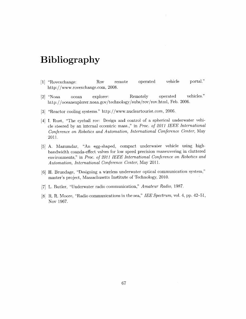
Bibliography
[1] "Rovexchange: Rov remote operated vehicle portal."http://www.rovexchange.com, 2008.
[2] "Noaa ocean explorer: Remotely operated vehicles."http://oceanexplorer.noaa.gov/technology/subs/rov/rov.html, Feb. 2006.
[3] "Reactor cooling systems." http://www.nucleartourist.com, 2006.
[4] I. Rust, "The eyeball rov: Design and control of a spherical underwater vehi-cle steered by an internal eccentric mass.," in Proc. of 2011 IEEE International
Conference on Robotics and Automation, International Conference Center, May2011.
[5] A. Mazumdar, "An egg-shaped, compact underwater vehicle using high-
bandwidth coanda-effect valves for low speed precision maneuvering in clutteredenvironments," in Proc. of 2011 IEEE International Conference on Robotics and
Automation, International Conference Center, May 2011.
[6] H. Brundage, "Designing a wireless underwater optical communication system,"master's project, Massachusetts Institute of Technology, 2010.
[7] L. Butler, "Underwater radio communication," Amateur Radio, 1987.
[8] R. R. Moore, "Radio communications in the sea," IEE Spectrum, vol. 4, pp. 42-51,Nov 1967.