2-d slideline contact - kit - scc
TRANSCRIPT
MSC/NASTRAN 103 Exercise Workbook 9-1
WORKSHOP PROBLEM 9
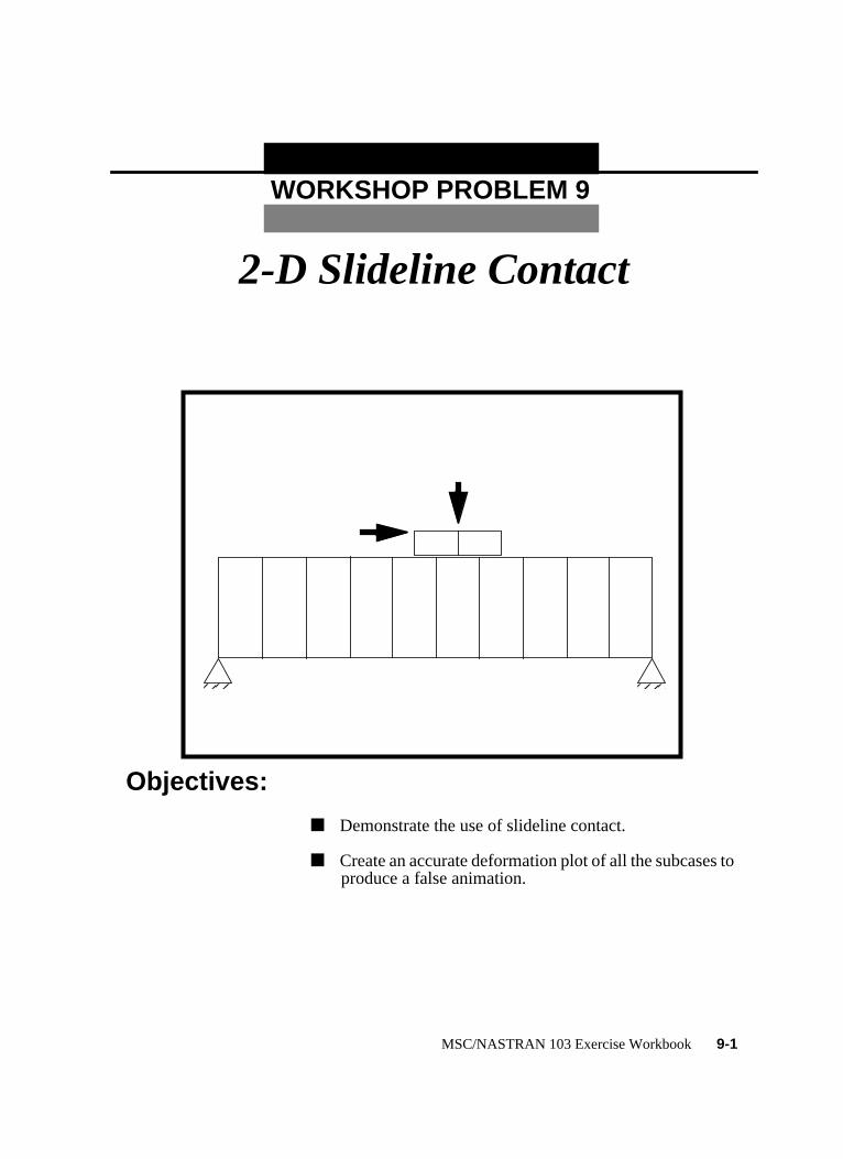
2-D Slideline Contact
Objectives:
■ Demonstrate the use of slideline contact.
■ Create an accurate deformation plot of all the subcases toproduce a false animation.

9-2 MSC/NASTRAN 103 Exercise Workbook

WORKSHOP 9 2-D Slideline Contact
Model Description:For the structure below:
Add Case Control commands and Bulk Data Entries to:
1. Model the contact between the block and the base.
4000 lb
10 inµ = .1
20x5x1 in
100x20x1 in
E = 1.1x10⁵ν = 0.0
MSC/NASTRAN 103 Exercise Workbook 9-3

ers.
6).
P,
Suggested Exercise Steps:
■ Modify the existing MSC/NASTRAN input file by addingthe appropriate nonlinear static analysis control paramet
■ Prepare the model for a nonlinear static analysis (SOL 10
■ Set up the appropriate subcase loading and analysisparameters (LOAD, NLPARM)
■ Input the necessary slideline contact parameters (BCONBFRIC, CORD2R, BLSEG).
■ Generate an input file and submit it to the MSC/NASTRANsolver for a nonlinear static analysis.
■ Review the results.
9-4 MSC/NASTRAN 103 Exercise Workbook

WORKSHOP 9 2-D Slideline Contact
Input File for Modification:prob9.dat
ID NAS103 WORKSHOP 9
TIME 300
SOL 106
CEND
$
TITLE = SLINE2S: SYMMETRIC ELASTIC PUNCH WITH FRICTION
$
DISP = ALL
SUBCASE 1 $ VERTICAL LOAD
LOAD = 1
NLPARM = 410
SUBCASE 2 $ DISPLACEMENT TO THE RIGHT
LOAD = 1
$
BEGIN BULK
PARAM,POST,-1
$
$ GEOMETRY
$
GRID,1,,0.,0.,0.,,123456 $
=,*1,,*(10.),== $
=9 $
GRID,12,,0.,20.,0.,,3456 $
=,*1,,*(10.),== $
=9 $
GRID,23,,45.,20.,0.,,3456 $
GRID,24,,55.,20.,0.,,3456 $
GRID,25,,65.,20.,0.,,3456 $
GRID,26,,45.,25.,0.,,3456 $
GRID,27,,55.,25.,0.,,3456 $
GRID,28,,65.,25.,0.,,3456 $
$
$ ELEMENTS
$
CQUAD4,1,1,1,2,13,12 $
=,*1,=,*1,*1,*1,*1 $
=8 $
CQUAD4,11,1,23,24,27,26 $
=,*1,=,*1,*1,*1,*1 $
MSC/NASTRAN 103 Exercise Workbook 9-5

PSHELL, 1, 1, 1., -1 $
MAT1, 1, 1.E5, , 0.0 $
$
$ PUNCH LOAD: VERTICAL LOAD
$
FORCE, 1, 26, , -1000., 0., 1., 0. $
FORCE, 1, 27, , -2000., 0., 1., 0. $
FORCE, 1, 28, , -1000., 0., 1., 0. $
$
$ LOAD FOR SUBCASE 2 : RIGHT HORIZONTAL DISPLACEMENT
$
$
$ SLIDELINE CONTACT
$
$
$ NONLINEAR SOLUTION STRATEGY: AUTO METHOD WITH DEFAULTS
$
NLPARM, 410, 1, , AUTO, , , PW, YES, +NLP41 $
+NLP41, , 1.E-6, 1.E-10 $
$
ENDDATA
9-6 MSC/NASTRAN 103 Exercise Workbook

WORKSHOP 9 2-D Slideline Contact
Exercise Procedure:1. Users who are not utilitizing MSC/PATRAN for
generating an input file should go to Step 15,otherwise, proceed to step 2.
2. Create a new database calledprob9.db.
In theNew Model Preference form set the following:
3. Those who do not wish to set up the model themselvesmay want to play the session file,prob9.ses. If you chooseto build the model yourself, proceed to the step 4.
The model has now been created. Skip toStep 11.
4. Create surfaces to represent the base and the block.
File/New...
New Database Name: prob9
OK
Tolerance: ● Default
Analysis Code: MSC/NASTRAN
Analysis Type: Structural
OK
File/Session/Play...
Session File List: prob9.ses
Apply
◆ Geometry
Action: Create
Object: Surface
Method: XYZ
Vector Coordinate List: <100, 20, 0>
MSC/NASTRAN 103 Exercise Workbook 9-7

5. Plant the mesh seed for mesh control.
6. Mesh the model with Quad4 elements.
Apply
Vector Coordinate List: <20, 5, 0>
Origin Coordinates List: [45, 20, 0]
Apply
◆ Finite Elements
Action: Create
Object: Mesh Seed
Type: Uniform
Number = 1
Curve List: (Select left edge of both surfaces.)
Apply
Number = 2
Curve List: (Select top edge of top surface.)
Apply
Number = 10
Curve List: (Select bottom edge of bottom surface.)
Apply
Action: Create
Object: Mesh
Type: Surface
Element Topology: Quad4
Surface List: (Select both surfaces.)
Apply
9-8 MSC/NASTRAN 103 Exercise Workbook

WORKSHOP 9 2-D Slideline Contact
7. Create the material property for the model.
8. Create the element property for the model.
◆ Materials
Action: Create
Object: Isotropic
Method: Manual Input
Material Name: mat_1
Input Properties...
Elastic Modulus = 1e5
Poisson’s Ratio= 0.0
Apply
Cancel
◆ Properties
Action: Create
Dimension: 2D
Type: Shell
Property Set Name prop_1
Input Properties...
Material Name m:mat_1
Thickness 1
OK
Select Members (Select both surfaces.)
Add
Apply
MSC/NASTRAN 103 Exercise Workbook 9-9

9. Create the boundary conditions for the model.
Using the following icon increase the node size to make the node morevisible for picking.
Create the nodal degree of freedom constraint for the entire model.
To clean up the display, use the following main menu icons:
Create the second model constraint.
◆ Loads/BCs
Action: Create
Object: Displacement
Type: Nodal
New Set Name: entire_model
Input Data...
Translations < T1 T2 T3 > < , , 0 >
Rotations < R1 R2 R3 > < 0, 0, 0 >
OK
Select Application Region...
Geometry Filter: ● FEM
Select Nodes: (Select all nodes in model.)
Add
OK
Apply
New Set Name: base_fixed
Input Data...
Translation < T1 T2 T3 > < 0, 0 , >
Node Size
Reset Graphics Refresh Graphics
9-10 MSC/NASTRAN 103 Exercise Workbook
WORKSHOP 9 2-D Slideline Contact
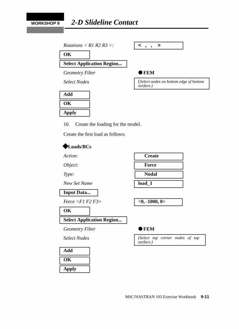
10. Create the loading for the model.
Create the first load as follows:
Rotations < R1 R2 R3 >: < , , >
OK
Select Application Region...
Geometry Filter ● FEM
Select Nodes (Select nodes on bottom edge of bottomsurface.)
Add
OK
Apply
◆ Loads/BCs
Action: Create
Object: Force
Type: Nodal
New Set Name load_1
Input Data...
Force <F1 F2 F3> <0, -1000, 0>
OK
Select Application Region...
Geometry Filter ● FEM
Select Nodes (Select top corner nodes of topsurface.)
Add
OK
Apply
MSC/NASTRAN 103 Exercise Workbook9-11
)
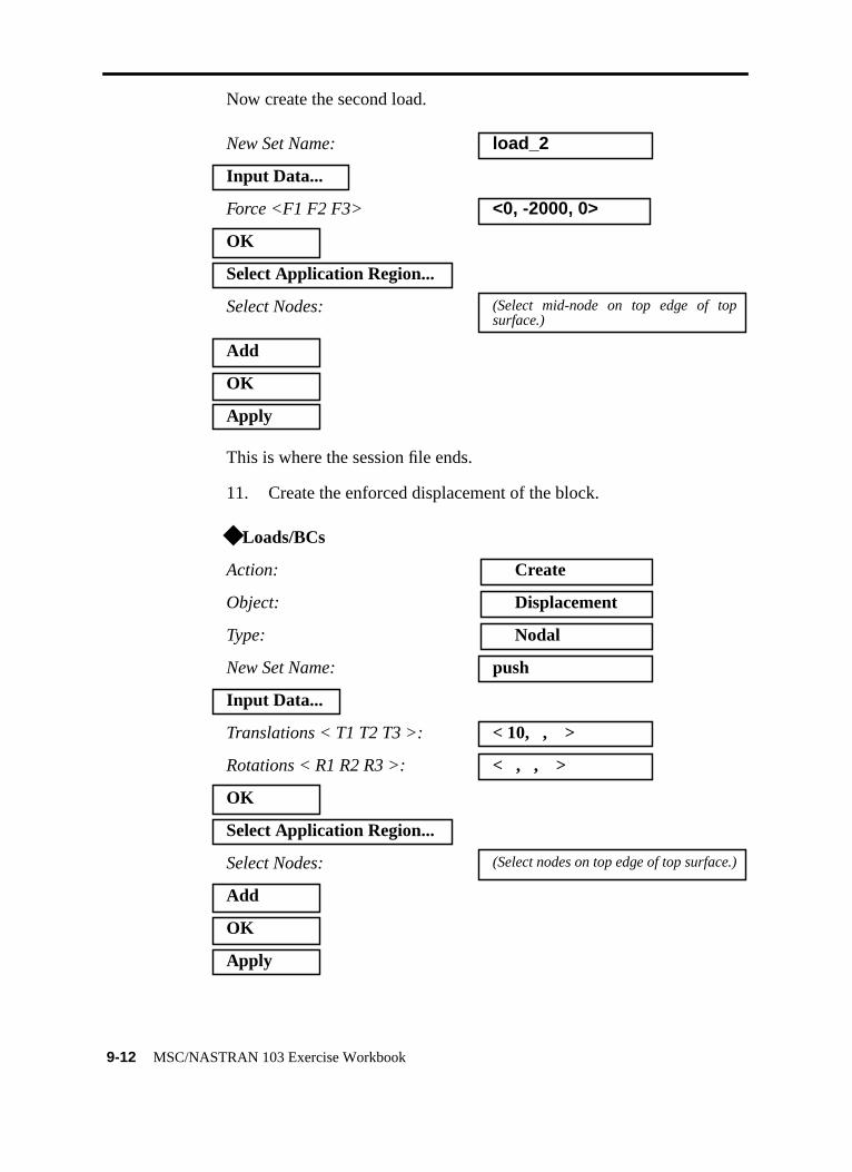
Now create the second load.
This is where the session file ends.
11. Create the enforced displacement of the block.
New Set Name: load_2
Input Data...
Force <F1 F2 F3> <0, -2000, 0>
OK
Select Application Region...
Select Nodes: (Select mid-node on top edge of topsurface.)
Add
OK
Apply
◆ Loads/BCs
Action: Create
Object: Displacement
Type: Nodal
New Set Name: push
Input Data...
Translations < T1 T2 T3 >: < 10, , >
Rotations < R1 R2 R3 >: < , , >
OK
Select Application Region...
Select Nodes: (Select nodes on top edge of top surface.
Add
OK
Apply
9-12 MSC/NASTRAN 103 Exercise Workbook
WORKSHOP 9 2-D Slideline Contact
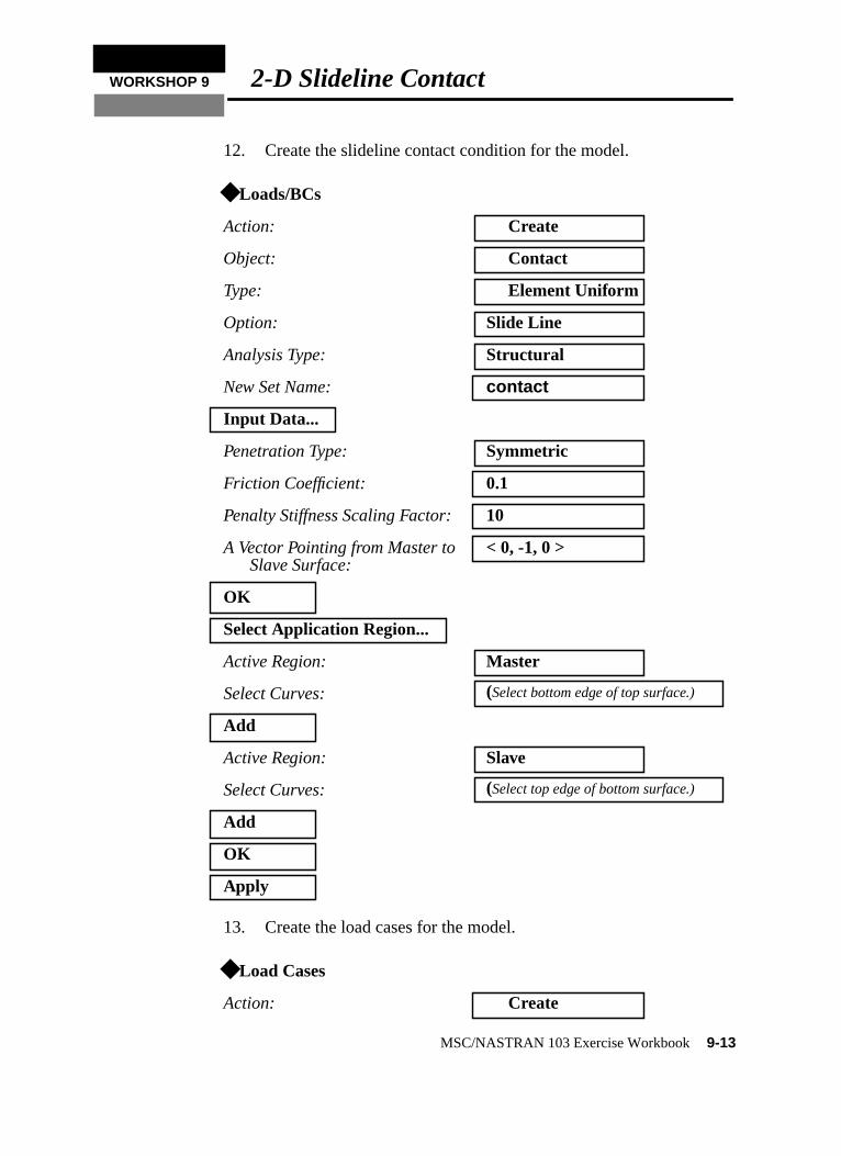
12. Create the slideline contact condition for the model.
13. Create the load cases for the model.
◆ Loads/BCs
Action: Create
Object: Contact
Type: Element Uniform
Option: Slide Line
Analysis Type: Structural
New Set Name: contact
Input Data...
Penetration Type: Symmetric
Friction Coefficient: 0.1
Penalty Stiffness Scaling Factor: 10
A Vector Pointing from Master toSlave Surface:
< 0, -1, 0 >
OK
Select Application Region...
Active Region: Master
Select Curves: (Select bottom edge of top surface.)
Add
Active Region: Slave
Select Curves: (Select top edge of bottom surface.)
Add
OK
Apply
◆ Load Cases
Action: Create
MSC/NASTRAN 103 Exercise Workbook9-13

Take care to be sure that the LBC Scale Factor for each Load/BC inspreadsheet equal 1.
14. Generate an input file for the analysis.
Click on theAnalysisradio button on the Top Menu Bar and set up theanalysis as follows:
Load Case Name: case_1
Assign/Prioritize Loads/BCs
Select Loads/BCs to Add toSpreadsheet
Conta_contactDispl_base_fixedDispl_entire_modelForce_load_1Force_load_2
OK
Apply
Load Case Name: case_2
Assign/Prioritize Loads/BCs
Select Loads/BCs to Add toSpreadsheet:
Displ_push
OK
Apply
◆ Analysis
Action: Analyze
Object: Entire Model
Method: Analysis Deck
Job Name prob9
Solution Type...
Solution Type ● NONLINEAR STATIC
OK
Subcase Create...
Available Subcases: case_1
9-14 MSC/NASTRAN 103 Exercise Workbook
WORKSHOP 9 2-D Slideline Contact
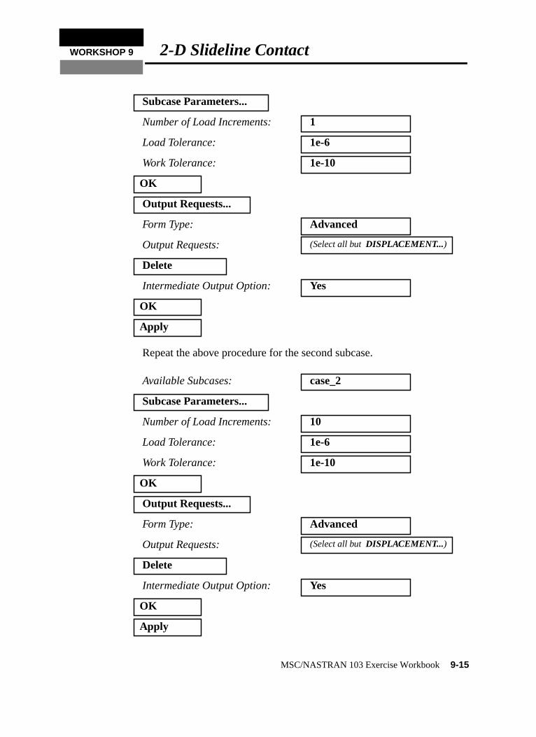
Repeat the above procedure for the second subcase.
Subcase Parameters...
Number of Load Increments: 1
Load Tolerance: 1e-6
Work Tolerance: 1e-10
OK
Output Requests...
Form Type: Advanced
Output Requests: (Select all butDISPLACEMENT...)
Delete
Intermediate Output Option: Yes
OK
Apply
Available Subcases: case_2
Subcase Parameters...
Number of Load Increments: 10
Load Tolerance: 1e-6
Work Tolerance: 1e-10
OK
Output Requests...
Form Type: Advanced
Output Requests: (Select all butDISPLACEMENT...)
Delete
Intermediate Output Option: Yes
OK
Apply
MSC/NASTRAN 103 Exercise Workbook9-15

t
Select both the subcases.
An input file calledprob9.bdf will be generated. This process oftranslating your model into an input file is called the ForwardTranslation. The Forward Translation is complete when the Heartbeaturns green. MSC/PATRAN users should now proceed toStep 16.
Cancel
Subcase Select...
Subcases for Solution Sequence: case_1case_2
Subcases Selected: (Deselect Default)
OK
Apply
9-16 MSC/NASTRAN 103 Exercise Workbook

WORKSHOP 9 2-D Slideline Contact
Generating an input file for MSC/NASTRAN Users:
15. MSC/NASTRAN users can generate an input file usingthe data from the Model Description. The result should besimilar to the output below (prob9.dat):
ASSIGN OUTPUT2 = ‘prob9.op2’ , UNIT = 12
ID NAS103 WORKSHOP 9 SOLUTION
TIME 300
SOL 106
CEND
$
TITLE = SLINE2S: SYMMETRIC ELASTIC PUNCH WITH FRICTION
$
DISP = ALL
SUBCASE 1 $ VERTICAL LOAD
LOAD = 1
NLPARM = 410
SUBCASE 2 $ DISPLACEMENT TO THE RIGHT
LOAD = 1
NLPARM=420
SPC=2
$
BEGIN BULK
PARAM,POST,-1
$
$ GEOMETRY
$
GRID,1,,0.,0.,0.,,123456 $
=,*1,,*(10.),== $
=9 $
GRID,12,,0.,20.,0.,,3456 $
=,*1,,*(10.),== $
=9 $
GRID,23,,45.,20.,0.,,3456 $
GRID,24,,55.,20.,0.,,3456 $
GRID,25,,65.,20.,0.,,3456 $
GRID,26,,45.,25.,0.,,3456 $
GRID,27,,55.,25.,0.,,3456 $
GRID,28,,65.,25.,0.,,3456 $
$
MSC/NASTRAN 103 Exercise Workbook9-17

$ ELEMENTS
$
CQUAD4,1,1,1,2,13,12 $
=,*1,=,*1,*1,*1,*1 $
=8 $
CQUAD4,11,1,23,24,27,26 $
=,*1,=,*1,*1,*1,*1 $
PSHELL, 1, 1, 1., -1 $
MAT1, 1, 1.E5, , 0.0 $
$
$ PUNCH LOAD: VERTICAL LOAD
$
FORCE, 1, 26, , -1000., 0., 1., 0. $
FORCE, 1, 27, , -2000., 0., 1., 0. $
FORCE, 1, 28, , -1000., 0., 1., 0. $
$
$ LOAD FOR SUBCASE 2 : RIGHT HORIZONTAL DISPLACEMENT
$
SPC, 2, 26, 1, 10.0
SPC, 2, 27, 1, 10.0, 28, 1, 10.0
$
$ SLIDELINE CONTACT
$
BCONP, 10, 40, 50, , 10., 60, 2, 70
BFRIC, 60, , , 0.1
BLSEG, 40, 12, 13, 14, 15, 16, 17, 18, +BLSG1
+BLSG1, 19, 20, 21, 22
BLSEG, 50, 25, 24, 23
CORD2R, 70, , 0., 0., 0., 0., 0., 1., +CRD10
+CRD10, 1., 0., 0.
$
$ NONLINEAR SOLUTION STRATEGY: AUTO METHOD WITH DEFAULTS
$
NLPARM, 410, 1, , AUTO, , , PW, YES, +NLP41 $
+NLP41, , 1.E-6, 1.E-10 $
NLPARM, 420, 10, , AUTO, , , PW, YES, +NLP42
+NLP42, , 1.E-6, 1.E-10
$
ENDDATA
9-18 MSC/NASTRAN 103 Exercise Workbook

WORKSHOP 9 2-D Slideline Contact
Submit the input file for analysis:
16. Submit the input file to MSC/NASTRAN for an analysis.
16a. To submit the MSC/PATRAN.bdf file, find an availableUNIX shell window. At the command prompt enternastran prob9.bdf scr=yes. Monitor the analysis usingthe UNIX pscommand.
16b. To submit the MSC/NASTRAN.dat file, find anavailable UNIX shell window and at the commandprompt enternastran prob9.dat scr=yes. Monitor theanalysis using the UNIX pscommand.
17. When the analysis is completed, edit theprob9.f06 fileand search for the wordFATAL . If no matches exist,search for the wordWARNING . Determine whether theexisting WARNING messages indicate any modelingerrors.
17a. While still editingprob9.f06, search for the word:
D I S P L A C E (spaces are necessary).
What are the x and y displacements of Node 23 at the endof the first subcase?
What are the x and y displacements of Node 23 at the endof the second subcase?
T1=
T2=
T1=
T2=
MSC/NASTRAN 103 Exercise Workbook9-19

Comparison of Results:
18. Compare the results obtained in the.f06 file with theresults on the following page:
9-20 MSC/NASTRAN 103 Exercise Workbook

WO
RK
SH
OP
92-D
Slideline C
ontact
1 R2 R3
0.0 0.00.0 0.00.0 0.00.0 0.00.0 0.00.0 0.00.0 0.0
1 R2 R3
0.0 0.00.0 0.00.0 0.00.0 0.00.0 0.00.0 0.00.0 0.0
MS
C/N
AS
TR
AN
103 Exercise W
orkbook9-21
LOAD STEP = 1.00000E+00 D I S P L A C E M E N T V E C T O R
POINT ID. TYPE T1 T2 T3 R . . .
22 G -3.213901E-03 2.042947E-03 0.0 0.023 G 4.799817E-04 -1.948305E-02 0.0 0.024 G -9.838412E-05 -2.636322E-02 0.0 0.025 G -6.764003E-04 -1.952910E-02 0.0 0.026 G 3.663775E-03 -3.048664E-02 0.0 0.027 G -8.672358E-05 -3.536061E-02 0.0 0.028 G -3.837358E-03 -3.053272E-02 0.0 0.0
LOAD STEP = 2.00000E+00 D I S P L A C E M E N T V E C T O R
POINT ID. TYPE T1 T2 T3 R . . .
22 G -4.396476E-03 1.590136E-03 0.0 0.023 G 9.993721E+00 -1.851050E-02 0.0 0.024 G 9.997439E+00 -2.663225E-02 0.0 0.025 G 1.000035E+01 -2.080630E-02 0.0 0.026 G 1.000000E+01 -2.875795E-02 0.0 0.027 G 1.000000E+01 -3.563613E-02 0.0 0.028 G 1.000000E+01 -3.255428E-02 0.0 0.0

19. This ends the exercise for MSC/NASTRANusers. MSC/PATRAN Users should proceed tothe next step.
20. Proceed with the Reverse Translation process, that is,importing theprob9.op2 results file into MSC/PATRAN.To do this, return to theAnalysis form and proceed asfollows:
21. Post process the results from the analysis.
Also, erase all the geometry from the screen.
Clean up the viewport by using the following main menu icon:
22. Next, bring up theResultsform to create a false animationof the deformation by plotting the deformation for eachload case.
Now we will generate the fringe plot of the model.
◆ Analysis
Action: Read Output2
Object: Result Entities
Method: Translate
Select Results File...
Selected Results File: prob9.op2
OK
Apply
Display / Plot/Erase...
Erase All Geometry
OK
◆ Results
Action: Create
Object: Fringe
Refresh Graphics
9-22 MSC/NASTRAN 103 Exercise Workbook

WORKSHOP 9 2-D Slideline Contact
Now click on theSelect Results icon.
Next click on theTarget Entities icon.
Note: This feature allows you to view fringe plots of specific elementsof your choice.
Click on theDisplay Attributes icon.
Note: TheDisplay Attributes form allows you the ability to changethe displayed graphics of fringe plots.
Now click on thePlot Options icon.
Select Result Case(s) (Select all cases.)
Select Fringe Result Displacements, Translational
Quantity: Magnitude
Target Entity: Current Viewport
Style: Discrete/Smooth
Display: Free Edges
Coordinate Transformation: None
Scale Factor 1.0
Apply
Select Results
Target Entities
Display Attributes
Plot Options
MSC/NASTRAN 103 Exercise Workbook9-23

The resulting fringe plot should display the displacement spectrumsuperimposed over the undeformed bar. The final fringe plotdisplaying the physical deformation of the model can be created asfollows:
Now click on theSelect Results icon.
Click on theDisplay Attributes icon.
In order to see the deformation results accurately, set the ScaleInterpretation to True Scale with a Scale Factor of 1.
Now click on thePlot Options icon.
Quit MSC/PATRAN when you have completed this exercise.
◆ Results
Action: Create
Object: Deformation
Select Result Case(s) (Select all cases.)
Select Deformation Result Displacements, Translational
Show As: Resultant
● True Scale
Scale Factor 1.0
■ Show Undeformed
Coordinate Transformation: None
Scale Factor 1.0
Apply
Select Results
Display Attributes
Plot Options
9-24 MSC/NASTRAN 103 Exercise Workbook

WORKSHOP 9 2-D Slideline Contact
MSC/PATRAN .bdf file: prob9.bdf$ NASTRAN input file created by the MSC MSC/NASTRAN input file
$ translator ( MSC/PATRAN Version 7.5 ) on January 15, 1998 at
$ 18:49:01.
ASSIGN OUTPUT2 = ‘prob9.op2’, UNIT = 12
$ Direct Text Input for File Management Section
$ Nonlinear Static Analysis, Database
SOL 106
TIME 600
$ Direct Text Input for Executive Control
CEND
SEALL = ALL
SUPER = ALL
TITLE = MSC/NASTRAN job created on 15-Jan-98 at 18:46:42
ECHO = NONE
MAXLINES = 999999999
$ Direct Text Input for Global Case Control Data
SUBCASE 1
$ Subcase name : case_1
SUBTITLE=case_1
NLPARM = 1
SPC = 2
LOAD = 2
DISPLACEMENT(SORT1,REAL)=ALL
$ Direct Text Input for this Subcase
SUBCASE 2
$ Subcase name : case_2
SUBTITLE=case_2
NLPARM = 2
SPC = 5
LOAD = 5
DISPLACEMENT(SORT1,REAL)=ALL
$ Direct Text Input for this Subcase
BEGIN BULK
PARAM POST -1
PARAM PATVER 3.
PARAM AUTOSPC YES
PARAM COUPMASS -1
PARAM K6ROT 100.
PARAM WTMASS 1.
PARAM LGDISP 1
PARAM,NOCOMPS,-1
MSC/NASTRAN 103 Exercise Workbook9-25

PARAM PRTMAXIM YES
NLPARM 1 1 AUTO 5 25 PW YES + A
* A 1.-6 1.-10 * B
* B
NLPARM 2 10 AUTO 5 25 PW YES + C
* C 1.-6 1.-10 * D
* D
$ Direct Text Input for Bulk Data
$ Elements and Element Properties for region : prop_1
PSHELL 1 1 1.
CQUAD4 1 1 1 2 13 12
CQUAD4 2 1 2 3 14 13
CQUAD4 3 1 3 4 15 14
CQUAD4 4 1 4 5 16 15
CQUAD4 5 1 5 6 17 16
CQUAD4 6 1 6 7 18 17
CQUAD4 7 1 7 8 19 18
CQUAD4 8 1 8 9 20 19
CQUAD4 9 1 9 10 21 20
CQUAD4 10 1 10 11 22 21
CQUAD4 11 1 23 24 27 26
CQUAD4 12 1 24 25 28 27
$ Referenced Material Records
$ Material Record : mat_1
$ Description of Material : Date: 21-Aug-97 Time: 11:49:06
MAT1 1 100000. 0.
$ Nodes of the Entire Model
GRID 1 0. 0. 0.
GRID 2 10. 0. 0.
GRID 3 20. 0. 0.
GRID 4 30. 0. 0.
GRID 5 39.9999 0. 0.
GRID 6 49.9999 0. 0.
GRID 7 60. 0. 0.
GRID 8 70. 0. 0.
GRID 9 80. 0. 0.
GRID 10 90. 0. 0.
GRID 11 100. 0. 0.
GRID 12 0. 20. 0.
GRID 13 10. 20. 0.
GRID 14 20. 20. 0.
GRID 15 30. 20. 0.
GRID 16 39.9999 20. 0.
GRID 17 49.9999 20. 0.
GRID 18 60. 20. 0.
9-26 MSC/NASTRAN 103 Exercise Workbook

WORKSHOP 9 2-D Slideline Contact
GRID 19 70. 20. 0.
GRID 20 80. 20. 0.
GRID 21 90. 20. 0.
GRID 22 100. 20. 0.
GRID 23 45. 20. 0.
GRID 24 55. 20. 0.
GRID 25 65. 20. 0.
GRID 26 45. 25. 0.
GRID 27 55. 25. 0.
GRID 28 65. 25. 0.
$ Loads for Load Case : case_1
SPCADD 2 4 6
LOAD 2 1. 1. 4 1. 6
$ Contact LBCs for Load Set : contact
BCONP 1 2 1 10. 1 2 1
BFRIC 1 .1
BLSEG 1 23 24 25
CORD2R 1 45. 20. 0. 45. 20. -1. + E
+ E 55. 20. 0.
BOUTPUT 1 23 24 25
BLSEG 2 22 21 20 19 18 17 16 + F
+ F 15 14 13 12
BOUTPUT 2 22 21 20 19 18 17 16 + G
+ G 15 14 13 12
$ Loads for Load Case : case_2
SPCADD 5 4 6 7
$ Enforced Displacements for Load Set : push
SPCD 5 26 1 10. 27 1 10.
SPCD 5 28 1 10.
LOAD 5 1. 1. 4 1. 6
$ Displacement Constraints of Load Set : entire_model
SPC1 6 3456 1 THRU 28
$ Displacement Constraints of Load Set : base_fixity
SPC1 4 12 1 THRU 11
$ Displacement Constraints of Load Set : push
SPC1 7 1 26 27 28
$ Nodal Forces of Load Set : load_1
FORCE 4 26 0 1000. 0. -1. 0.
FORCE 4 28 0 1000. 0. -1. 0.
$ Nodal Forces of Load Set : load_2
FORCE 6 27 0 2000. 0. -1. 0.
$ Referenced Coordinate Frames
ENDDATA c49a29de
MSC/NASTRAN 103 Exercise Workbook9-27

9-28 MSC/NASTRAN 103 Exercise Workbook